parts and more compact picks valid from 2012
TRANSCRIPT

RoAd And MineRAl tecHnologies
parts and more CompaCtpiCksvalid from 2012
www.wirtgen-group.com

Contents

2 I 3
AdvAntAges PAge 4
Original Wirtgen picks Page 4
Quality tools Page 6
FActs PAge 8
The components of a pick Page 8
The carbide tip Page 10
The brazing Page 12
The steel body Page 14
The wear plate Page 16
The clamping sleeve Page 18
The Twin-Head system Page 22
APPlicAtion PAge 24
Pick designation Page 24
Pick selection Page 25
Examples of pick designations Page 30
The advantages of carbide tips M and ML Page 32
Wear of picks Page 34
Optimum wear Page 36
Cutting length and chip volume Page 40
Milling depth and wear Page 44
Wear patterns (optimum) Page 46
Selection tables Page 50
System comparison Twin-Head Page 56
Wear patterns (undesirable) Page 58
Contents

AdvAntAges | FActs | ApplicAtion
good economy is well worthwhileEconomy as the relationship between the success achieved and equipment used depends on many factors, particularly in the case of complex construction machines. In this respect, the cutting technology, and especially the pick as an outstanding product of Wirtgen cutting, plays a central role.The formula “A low pick price results in good economy” does not apply in this case.
Pick
original Wirtgen piCks

4 I 5
Road milling machine Stabilizer
A look at reality shows: The list of influencing factors is long and varied. Starting with the longer service life of the tools, to the minimization of stop-page times by means of ease of use and on to the high level of specialization for the many different applications. The con-sumption of picks can be reduced significantly.
this brochure gives you the opportunity to get to know the full range of Wirtgen picks for road milling machines, recyclers and stabilizers, enabling you to find the most economical option for your construction site operations in every situation.
original Wirtgen piCks

AdvAntAges | FActs | ApplicAtion
competent partnershipWhen construction machine and tool manufacturers pool their expertise, this has many benefits for you as the customer.This close cooperation allows rapid reaction to the needs and suggestions of customers. The design and production of all types of cutting tools at BETEK, perfectly matched to the differ-ent machine types of Wirtgen, ensure the maximum perfor-mance capability of both the machine and pick in service.
Quality tools for high-performanCe milling maChines

6 I 7
this close cooperation shows:Due to their individual design, picks are not classical bought-in parts. Only in combination with the corresponding, highly spe-cialised Wirtgen machines can this regularly give the optimum milling result with maximum productivity.
summary: the combination of both these areas of expertise forms the basis for the best possible service and greatest economy of your machines in daily use.
Quality tools for high-performanCe milling maChines

AdvAntAges | FActs | ApplicAtion
1
2
3
4
5
the Components of a piCk

8 I 9
Picks for road milling machines, recyclers and stabilizers usually consist of five components:
1 Carbide tip
2 Brazing
3 Steel body
4 Wear plate
5 Clamping sleeve
The design varies from pick to pick, since they are designed for different application areas, although the components and their function are always identical.
Road milling pick W7 / 20 Stabilizing pick W1-17 / 22
the Components of a piCk

AdvAntAges | FActs | ApplicAtion
the Carbide tip – tungsten Carbide and Cobalt With a perfeCt bond
The carbide in our tips is a composite material made from tungsten carbide and cobalt. While the tungsten carbide pro-vides extreme hardness and resistance to wear, the compara-tively “soft” cobalt bonds the tungsten carbide particles to en-sure maximum breaking strength under even the greatest stresses.
1 Carbide under the microscope
2 Cobalt is deformed and creates a bond between the tungsten car-bide particles, with a proportion by weight of approx. 6%.
3 Tungsten carbide is very hard, and provides the wear resistance, with a proportion by weight of approx. 94%.
1

10 I 11
the Carbide tip – tungsten Carbide and Cobalt With a perfeCt bond
2 3
The balanced mixture of different particle sizes of the tungsten carbide largely determines the wear of the tips. The fine parti-cles ensure high wear resistance, while the coarse particles provide the necessary breaking strength and temperature re-sistance. The incorrect mixing ratio of coarse and fine particles causes increased wear in the high-temperature cutting pro-cess, which results in premature failure of the tool.
Stringent quality controls at BETEK ensure the consistent and correct mixing ratio.
summary: the quality of the carbide determines the service life of the pick, and consequently also the machine avail-ability, its milling performance and the quality of your site operations.

AdvAntAges | FActs | ApplicAtion
the brazing – reliable hold of the Carbide tip on the steel body
The carbide tips are brazed firmly to the steel body. Since the carbide in the tip and the steel in the steel body expand at dif-ferent rates as soon as the enormously high temperatures gen-erated in the milling process act on the components, we use a brazing process developed in-house, which under the effect of heat ultimately determines the hardness of the steel body.
This is confirmed by numerous stress tests: Even under enor-mous pick stresses, no breakage occurs. The carbide tip and steel body hold firmly together.
The brazing
summary: the careful brazing of the tungsten carbide tip and the steel body ensure the firm bond of the materials.

12 I 13
the brazing – reliable hold of the Carbide tip on the steel body

AdvAntAges | FActs | ApplicAtion
The pick head must withstand enormous shear forces and impact stresses. At the same time, the pick must sit firmly and unbreakably in the toolholder throughout its complete service life. Wirtgen picks have a steel body which perfectly combines the two properties of wear resistance and breaking strength.
Different hardness levels for the pick head and shaft are pro-duced in a special operation: While the tough pick shaft absorbs the forces occurring in the area of the toolholder, the pick head undergoes extra hardening, making it particularly wear-resistant in direct contact with the milling material.
Put to the test: A 300 kg weight hits the pick from a height of 1.5 m
the steel body – hard at the top and tough at the bottom

14 I 15
summary: the relationship of hardness to toughness of the pick head and shaft largely determine the service life and usability of the pick.
the steel body – hard at the top and tough at the bottom

AdvAntAges | FActs | ApplicAtion
the Wear plate – Wear proteCtion and installation aid
Wear protectionThe design of the pick plays a decisive role for the wear char-acteristics of the toolholder. Wirtgen picks are therefore de-signed with a wear plate exactly matched to the toolholder, which completely covers the upper part of the toolholder (the plate outer diameter is 45 mm), and therefore absorbs a large part of the wear stress.

16 I 17
the Wear plate – Wear proteCtion and installation aid
Wirtgen picks have been optimized based on the requirements and experience from the field. The wear plates are 5 mm thick and have now been additionally reinforced with a further 2 mm at the outer edge to 7 mm. This feature ensures longer and bet-ter toolholder protection compared to conventional wear plates. The forged wear plate has a pronounced chamfer on the un-derside with which the pick is precisely centred in the bore.
the installation aidIn the delivery condition, the clamping sleeve of the pick is pre-tensioned by the wear plate. Therefore, only a few operations are required to install the pick ready for use.
Eff ective protection: The wear plate completely covers the toolholder contact surface.
summary: the wear plate ensures even wear of the toolholder contact surface and reduced lengthwise wear of the toolholders, and also enables easy and quick installation of the pick.

AdvAntAges | FActs | ApplicAtion
thanks to its exact roundness, the twin-stop clamping sleeve ensures optimum pick rotation characteristics.The Twin-Stop function with an upper and lower stop enables the clearly defined lengthwise play of the pick under the chang-ing stresses during the cutting process. This dramatically re-duces the risk of damage to the sleeves and/or the number of pick breakages.
The clamping sleeve for the current range of picks has a wall thickness of 1.25 mm and has therefore been reinforced throughout. This optimization significantly extends the possible use of the shaft-sleeve joint.
The lower gap width (see Figure 1) results in a larger contact area between the toolholder bore and sleeve jacket. The com-
1 The Twin-Stop clamping sleeve with improved rota-tion characteristics
2 Conventional clamping sleeve with an axial stop in the unprotected area
3 Twin-Stop stops in the protected area for re-duced wear
1
paratively high hardness of the clamping sleeve ensures a high clamping force, which counteracts premature failure in even the most demanding applications. A special protective film pro-tects the sleeve against corrosion and therefore enables the easy dismantling of the pick.
the Clamping sleeve – strong hold and QuiCk replaCement

18 I 19
summary: the holding force is great enough to guarantee a reliable milling process in every situation, and simulta-neously low enough to allow uncomplicated and quick pick replacement.
2 3
the Clamping sleeve – strong hold and QuiCk replaCement

AdvAntAges | FActs | ApplicAtion
the Clamping sleeve –improved sealing and rotation
The guided clamping sleeve has been introduced with the cur-rent product range. With this design feature the clamping sleeve is centred in the wear plate also in the mounted state. The steel body, the wear plate and the clamping sleeve form a labyrinth seal that reduces the penetration of dirt into the tool-holder bore (see illustration on right).
The penetration of particles of milled material into the toolhold-er bore and the cavity between the clamping sleeve and pick shaft usually leads to degradation of the rotation characteris-tics. The clamping sleeve wear is significantly accelerated and the pick must be replaced earlier.

20 I 21
the Clamping sleeve –improved sealing and rotation
Conventional wear plate-clamping sleeve-construction
Current wear plate-clamping sleeve-construction

AdvAntAges | FActs | ApplicAtion
the tWin-head system –piCks With 22 mm shaft diameter
the twin-Head pick generation has been optimized with regard to the wear mechanisms occurring with stabilizer and recycler picks with 22 mm shaft diameter, because these place quite different requirements on the individual components.
Experience has shown that in this segment in particular, the pick head is also subject to wear, in addition to the carbide tip. Previous standard tools obtain their material characteristics such as hardness and toughness due to the brazing process.

22 I 23
the tWin-head system – piCks With 22 mm shaft diameter
By decoupling of the cone, a range of previously unachievable combinations of characteristics can be realized.
the core of the pick and carrier of the carbide is particularly tough, and therefore less prone to breakage, while the jack-et, i.e. the wear cone, is particularly hard and resistant.
The wear cone mounted on the pick head is particularly solid and massive, in order to guarantee reduced and even wear of all components (carbide tip, wear cone, etc.).
In applications involving extreme ground conditions, tool break-age sometimes occurs due to rocks or reinforcement. Since in the Twin-Head generation (with 22 mm shaft diameter) the cone is made of significantly more wear-resistant material than the pick head of conventional picks, the toolholder remains pro-tected longer, even following complete loss of the carbide tip.
if a pick replacement can no longer be pushed on, it can, like all picks, be easily fitted by means of the pre-tensioned clamping sleeve and fitted with little effort.

AdvAntAges | FActs | ApplicAtion
piCk designation
Designation Significance
W Wirtgen pick
Designations for cap-shaped carbide tips
W4 Basic diameter 16 mm (Length: 16 mm)
W5 Basic diameter 17.5 mm (Length: 16 mm)
W5L Basic diameter 17.5 mm (Length: 17.5 mm)
W6 Basic diameter 19 mm (Length: 17.5 mm)
W6L Basic diameter 19 mm (Length: 19.5 mm)
W6C Basic diameter 19 mm (Length: 10 mm)
W6M Basic diameter 19 mm (Length: 18 mm)
W6ML Basic diameter 19 mm (Length: 21 mm)
W7 Basic diameter 20.5 mm (Length: 20.5 mm)
W8 Basic diameter 22 mm (Length: 20 mm)
W8M Basic diameter 22 mm (Length: 21.5 mm)
Designations for cylindrical carbide tips
W1-8 Carbide tip diameter 8 mm (Length: 15 mm)
W1-10 Carbide tip diameter 10 mm (Length: 25 mm)
W1-13 Carbide tip diameter 13 mm (Length: 25 mm)
W1-15 Carbide tip diameter 15 mm (Length: 24 mm)
W1-17 Carbide tip diameter 17 mm (Length: 28.5 mm)
W1-19 Carbide tip diameter 19 mm (Length: 29 mm)

01 Carbide tips
a)
02 Pick heads
03 Shaft design
shaft diameter20 mm
shaft diameter22 mm
shaft diameter25 mm
the selection of the right pick is decisive for your success.
Due to the many different application areas in the field of road construction and stabilization, the following graphic provides you with an overview of the variety of Wirtgen picks – a range designed because of the host of possible applica-tions with Wirtgen machines.
The tabular overview (pages 24 and 29) provides you with a detailed overview of the different pick designa-tions, including all available all possible dimensions and descriptions.
01 the carbide tips
a) Cap-shaped carbide tips with 5 different base diameters and lengths (W4, W5, W6, W7, W8).
b) Cap-shaped carbide tips in longer version have the additional designation letter L (e.g. W5L, W6L).
c) The cap-shaped carbide tip W6C has the same diameter as the W6 tip. The greatly flattened tip has been specially de-signed for stony ground in the application area of ground stabilization.
the right piCk seleCtion

a)
a)
b)
b)
c) d) e)
shaft diameter20 mm
shaft diameter22 mm
shaft diameter25 mm
AdvAntAges | FActs | ApplicAtion
d) The cap-shaped carbide tips W6M and W8M have the same diameter as the W6 and W8 tips. The tips are equipped with webs, and are used in special applications (soft top layer and hard substrate). The tip W6M is available in a longer version with the additional designation letter L (W6ML).
e) Cylindrical carbide tips with the code W1 are available in six different sizes (- 8, - 10, - 13, - 15, - 17, - 19). The number after the dash indicates the diameter of the tips in millimetres.
02 the pick heads
a) Standard-pick head without extractor groove.
the right piCk seleCtion

b) c)
c)
f) g) h)
d)
shaft diameter20 mm
shaft diameter22 mm
shaft diameter25 mm
b) Pick heads with extractor groove can be identified by the addi-tional designation letter -G (Groove – only relevant for picks with a shaft diameter of 20 mm).
c) Pick heads in reinforced version are characterized by the addi-tional letter -V (Voluminous – only relevant for picks with a shaft diameter of 20 mm) and constitute the group of stabilization and recycling picks enlarged volume.
d) Extended pick heads with embedded, cylindrical carbide tip.
e) Pick heads in slender version are designated by the additional letter -N (Narrow – only relevant for picks with a shaft diameter of 20 mm/with additional extractor groove the designation letter is -NG).
the right piCk seleCtion

d)
e)
i)
shaft diameter20 mm
shaft diameter22 mm
shaft diameter25 mm
25 I 28
f) Particularly large pick head with cylindrical carbide tip for stabilization of stony ground and recycling applications (only for Ø 22 mm shaft).
g) The two-in-one pick head (Twin-Head) has a wear cone, in-stead of a conventional wear plate, which simultaneously forms the holder protection and the pick head (only for Ø 22 mm shaft).
h) Large and robust pick head with cap-shaped carbide tip for ground stabilization and cold recycling under extreme condi-tions (only for Ø 25 mm shaft).
i) Large pick head with cylindrical carbide tip for ground stabili-zation and cold recycling under extreme conditions (only for Ø 25 mm shaft).
03 the shaft design
a) Pick shafts for road milling machines (Ø 20 mm) with increased wall thickness of the Twin-Stop clamping sleeve and a reinforced wear plate.
b) Pick shafts (Ø 22 mm) with Twin-Stop clamping sleeve and 45 mm wear plate with additionally reinforced edge.
c) Pick shafts (Ø 22 mm) with Twin-Stop clamping sleeve and wear cone.
d) Pick shafts (Ø 25 mm) with Twin-Stop clamping sleeve and 60 mm wear plate with additionally reinforced edge.
the right piCk seleCtion

24 I 29
Designation Significance
Shape of the carbide tip
C Compact Flat version
L Long Longer version (height)
M Massive Solid version
Shape of the steel body (of the pick head)
-G Groove With extractor groove
-N Narrow Narrow version
-T Twinhead With wearing cone
-V Voluminous Reinforced version (more volume)
-S Short Shortened version
Shaft diameter data for the pick
/ 13 Shaft diameter 13 mm
/ 20 Shaft diameter 20 mm
/ 22 Shaft diameter 22 mm
/ 25 Shaft diameter 25 mm

AdvAntAges | FActs | ApplicAtion
eXamples for piCk designations
Pick Designation Significance
W6ML-G/20
W6Cap-shaped carbide tip, base diameter 19 mm
M Solid carbide tip
L Longer carbide tip
-G Steel body with extractor groove
/20 Shaft diameter of the pick is 20 mm

30 I 31
eXamples for piCk designations
Pick Designation Significance
W6C-T/22
W6Cap-shaped carbide tip, base diameter 19 mm
C Flat carbide tip
-T Steel body with wear cone
/22 Shaft diameter of the pick is 22 mm

AdvAntAges | FActs | ApplicAtion
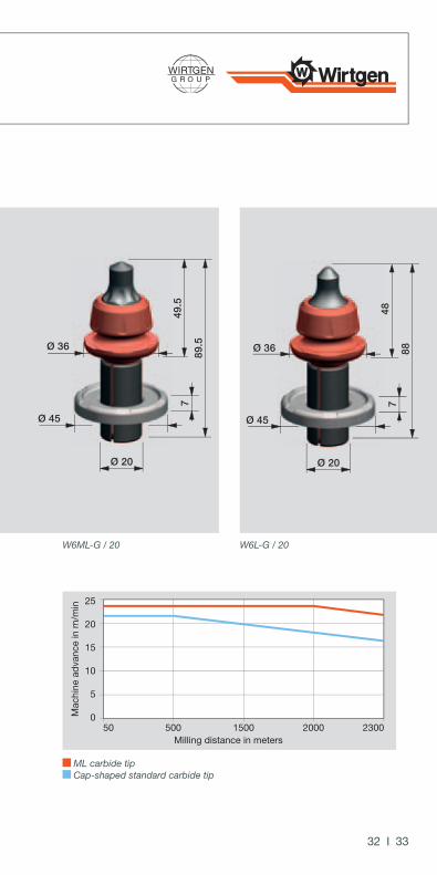
the advantages of Carbide tips m and ml
clever in the design
The carbide tips with the designation letter M are of a geomet-rically more solid design than those of the standard picks with-out this additional designation. Type ML (longer solid carbide tip) in particular features drastically extended cutting perfor-mance and maximum service life.The new design combines the reduced cutting forces of a cy-lindrical tip with the protection function of the cap-shaped carbide.
Due to the clever design of the carbide tip, the carbide is used in those places where it is required and can actually be utilized by the customer. This optimization of the shape brings enor-mous advantages particularly in applications with extreme car-bide wear. Due to the design characteristics, constant machine advance over an extended period can be ensured (see illustra-tion below).
Carbide tip in ML design (have up to 25.3% more wear vol-ume in the upper, cutting area.)
Carbide tip in cap-shaped standard design
Mac
hine
adv
ance
in m
/min
Milling distance in meters
5
0
10
15
20
25
50 500 1500 2000 2300
32 I 33
the advantages of Carbide tips m and ml
W6ML-G / 20 W6L-G / 20
Ø 45
49.5
89.5
Ø 20
Ø 36
7
Ø 45
48
88
Ø 20
Ø 36
7
ML carbide tip Cap-shaped standard carbide tip

AdvAntAges | FActs | ApplicAtion
Wear on piCks – reasons and tips for maintenanCe
All elements of a pick are subject to more or less wear depend-ing on the material to be milled. In case of excessive fatigue on one of the components, e.g. the carbide tip, the steel body, the wear plate and/or the clamping sleeve, the pick should be re-placed to prevent or reduce consequential damage to the more expensive toolholder system, which is also more complex to replace.
Dirt, incorrect installation or elements from different manufac-turers that are not identical will degrade not only the productiv-ity and/or the milling performance, but can even result in ir-reparable damage to the entire milling drum.
the most common reasons for unusually short pick service lives include:�� Coatings and accumulations of old milling material
(unsatisfactory cleaning)�� Selection of the wrong pick (see usage recommendations)�� Inadequate supply of water by the sprinkler system in the
milling drum housing�� Low quality of competitor products
What is wear?
Wear is produced by two elements pressing against each other with relative movement (for example between carbide tip and the material to be milled). During this process small particles become detached from the surfaces of both elements.

34 I 35
Wear on piCks – reasons and tips for maintenanCe
How can wear be avoided?
Wear on picks cannot be prevented entirely, but at best minimized. An adequate water supply is an important basic prerequisite to ensure the necessary rotation of the picks. The selection of the correct pick (depending on the substrate to be milled) also opti-mizes the use and reduces the wear.
increasing service life means�� paying attention to thorough, daily cleaning,�� regularly inspecting the picks so that wear or damage to
components can be tackled in good time,�� regularly maintaining and checking the sprinkler system and�� selecting the cutting tools to suit the application.
correct installation of the picks�� Check the amount of dirt and the possible need for cleaning
of the toolholder bore prior to the actual installation.�� Usage of appropriate tools to prevent damage to the
carbide tip (copper hammer or pneumatic insertion tool).�� Manual inspection of the pick rotation
(turning the pick by hand).

AdvAntAges | FActs | ApplicAtion
The correct assessment of the wear to Wirtgen picks is an es-sential requirement for smooth and efficient project handling. Replacing a pick at the right time guarantees successful work-ing, and ultimately also reduces operating costs significantly.
Many influencing factors must be taken into account when assessing the condition of picks: From the milling material to the weather, the machine performance, the machine advance speed and on to proper maintenance. Wear patterns and ob-servation of the maximum wear lengths help to avoid missing the correct replacement time, and prevent typical errors in applications.
the optimum Wear of the piCks
Designation Part No. Pick new (A) Pick worn out (B) Wear path (C)
W1-8/13 193701 54.2 43.6 10.6
W4/13 182598 54.2 44.5 9.7
W1-10-NG/20 2218467 88 68.2 19.8
W1-10-G/20 2218466 88 68.2 19.8
W1-13/20 2218475 88 69.8 18.2
W4-G/20 2218469 88 78.3 9.7
W5-G/20 2218470 88 79.1 8.9
W5/20 2218476 88 79.1 8.9

BC
A
36 I 37
the optimum Wear of the piCks
Pick new Pick worn out
Designation Part No. Pick new (A) Pick worn out (B) Wear path (C)
W1-8/13 193701 54.2 43.6 10.6
W4/13 182598 54.2 44.5 9.7
W1-10-NG/20 2218467 88 68.2 19.8
W1-10-G/20 2218466 88 68.2 19.8
W1-13/20 2218475 88 69.8 18.2
W4-G/20 2218469 88 78.3 9.7
W5-G/20 2218470 88 79.1 8.9
W5/20 2218476 88 79.1 8.9

AdvAntAges | FActs | ApplicAtion
the optimum Wear of the piCks
Designation Part No. Pick new (A) Pick worn out (B) Wear path (C)
W5L/20 2214877 89.5 79.8 9.7
W6-G/20 2218471 88 78.3 9.7
W6/20 2218478 88 78.3 9.7
W6L-G/20 2218472 88 76.2 11.8
W6L/20 2218480 88 76.2 11.8
W6M/20 2218486 88.6 78.2 10.4
W6ML-G/20 2218488 89.5 76.1 13.4
W7-G/20 2218473 88 75.9 12.1
W7/20 2152111 88 75.9 12.1
W8M-G/20 2218474 88 75.2 12.8
W8M/20 2218482 88 75.2 12.8
W6-V/20 2218485 88 78.3 9.7
W6C-V/20 2218489 80.5 78.3 2.2
W1-13/22 2088111 91 72.8 18.2
W1-17/22 2088112 91 74 17
W6-T/22 2143715 91.5 81.8 9.7
W6M-T/22 2143716 92.1 81.7 10.4
W6C-T/22 2143714 84 81.8 2.2
W8-T/22 2143717 91.5 80.4 11.1
W1-13-S/25 2218500 101 82.8 18.2
W1-15-S/25 2179693 101 84.9 16.1
W1-15/25 2143497 113 96.9 16.1
W1-19/25 2143499 113 97.5 15.5
W6C/25 2143486 113 110.8 2.2
W8/25 2143236 113 101.9 11.1

38 I 39
the optimum Wear of the piCks

AdvAntAges | FActs | ApplicAtion
Cutting length and Chip volume
in the three functional examples given the same milling drum type is used. The diameter of the cutting circle is 1140 mm, the milling drum operating speed is 98 1/min. As can be seen in the illustrations and data, the maximum advance (V) of the road milling machine reduces with increasing cutting depth (A).
explanation:
In example 1 the cutting depth is 50 mm. Referred to the cir-cumference of the milling drum the percentage of picks in con-tact is 11%. An advance performance of aptrox 30 m/min is achieved. For comparison the cutting depth in the third example is 300 mm. 18% of the milling drum circumference is in the cut, which has the consequence that the engine power applied is distributed over a greater number of picks and as a result the machine advance is reduced.
Given constant ambient conditions (machine, milling material, pick type, etc.) the milling depth (A) has a direct effect on the advance of the machine. Accordingly, the volume of comma-shaped chips milled also changes as a function of the machine parameters described above. The maximum milling material volume performance is achieved at a medium milling depth.

V
V
V
AA
A
40 I 41
Cutting length and Chip volume

AA
B
B
AdvAntAges | FActs | ApplicAtion
Cutting length and Chip volume
Example 1
Example 2
Cutting process
Milling depth (A)
Remaining web height (B)
Rotations per minute
Advanced Speed
Total circum-ference of the milling drum
Length of the contact friction (circumference in cutting process)
Example 1 50 mm 18.56 mm approx. 98 1/min. approx. 30 m/min approx. 3700 mm approx. 408 mm (11%)
Example 2 150 mm 2.38 mm approx. 98 1/min. approx. 10 m/min approx. 3700 mm approx. 474 mm (14%)
Example 3 300 mm 1.1 mm approx. 98 1/min. approx. 5 m/min approx. 3700 mm approx. 632 mm (18%)

A
B
42 I 43
Cutting length and Chip volume
the relationship between cutting depth and advance per-formance can also be read from the resulting chip length. The deeper the cut, the longer the contact friction with the compacted substrate lasts. The duration of the friction results in higher wear.
Example 3
Cutting process
Milling depth (A)
Remaining web height (B)
Rotations per minute
Advanced Speed
Total circum-ference of the milling drum
Length of the contact friction (circumference in cutting process)
Example 1 50 mm 18.56 mm approx. 98 1/min. approx. 30 m/min approx. 3700 mm approx. 408 mm (11%)
Example 2 150 mm 2.38 mm approx. 98 1/min. approx. 10 m/min approx. 3700 mm approx. 474 mm (14%)
Example 3 300 mm 1.1 mm approx. 98 1/min. approx. 5 m/min approx. 3700 mm approx. 632 mm (18%)

50 100 150 200 250 300
100
25
50
75
100
125
150
175
200
225
250
275
300
325
350
200 300 400 500 600A
C
B
AdvAntAges | FActs | ApplicAtion
milling depth and resulting Wear to piCks
in addition to the material in question, the most important influencing factors for the milling performance are the mill-ing depth and the machine advance speed.

44 I 45
milling depth and resulting Wear to piCks
summary and practical tip: in some applications, the re-quired milling depth is greater than 200 mm; in this case, it may be well worthwhile to remove the layers in several operations (cuts), since the advance per cut is increased and the wear to the picks per cubic metre can be reduced.
A Travel of the pick per cut in mmB Milling depth in mmC Theoretical milling volume in m³/h
Travel of the pick per cut in mm Theoretical milling volume (solid material) in m³/h Area of maximum milling volume performance
A major but often overlooked detail: At different milling depths, the cutting profile of the pick and therefore the chip size of the milled material differ significantly (also see examples page 40 to 43).
This has a direct effect on the milling performance and the wear to picks and toolholders. Wirtgen large milling machines produce the maximum milling performance and lowest wear costs at a milling depth of from 75 mm to 150 mm.
it can therefore be said in summary that the maximum economy can be achieved at these milling depths.

AdvAntAges | FActs | ApplicAtion
Picks with a cap-shaped carbide tip
This shows an example of an ideally worn pick. This can be seen from the carbide tip worn to the maximum and the even radial wear to the pick head.
the optimum Wear to the piCks – Wear patterns

Picks with a cap-shaped carbide tip and chamfered wear plate
This result is almost ideal, since here too the pick shows radial wear, as in the previous example. In the further milling process, the operator should keep an eye on the condition of the already very chamfered wear plate, because if it becomes too severely worn, it no longer protects the toolholder properly against wear to its contact surface.
the optimum Wear to the piCks – Wear patterns

Picks with a cylindrical carbide tip
The figure shows an optimally worn pick with optimum rota-tion, which is completely worn over its whole length, and must therefore be replaced.
the optimum Wear to the piCks – Wear patterns

46 I 49
Picks with a cap-shaped carbide tip
Good general condition of the pick with the exception of the wear plate. This is too severely worn in terms of its diameter. The steel body (with tip) however is only one-third worn. The pick indicates optimum rotation characteristics.
the optimum Wear to the piCks – Wear patterns

seleCtion table of piCks for road milling maChines
generally recommendable
recommendable for soft material not recommendable
Carbide tip Part No
Small milling machines Medium-sized milling machines Large milling machines
W 350, W 350 E
W 35, W 35 DC W 500 W 50 W 50 DC 500 DC,
W 600 DC W 1000 L W 1000 W 60, W 100
W 100 F, W 1000 F
W 120 F, W 1200 F
W 130 F, W 1300 F W 150 1300 -
1500 DC1900 - 2000 DC W 1500 W 1900 W 200 W 2000 W 210 2100 DC W 2100 W 2200 W 250
Asphalt pavements
W4/13 182598
W4-G/20 2218469
W5-G/20 2218470
W5/20 2218476
W5L/20 2218477
W6-G/20 2218471
W6/20 2218478
W6L-G/20 2218472
W6L/20 2218480
W6M/20 2218486
W6ML-G/20 2218488
W7-G/20 2218473
W7/20 2152111
W8M-G/20 2218474
W8M/20 2218482
Beton
W1-8/13 193701
W1-10-NG/20 2218467
W1-10-G/20 2218466
W1-13/20 2218475
Abr
asiv
enes
s of
the
mat
eria
l to
be m
illed

seleCtion table of piCks for road milling maChines
generally recommendable
recommendable for soft material not recommendable
Carbide tip Part No
Small milling machines Medium-sized milling machines Large milling machines
W 350, W 350 E
W 35, W 35 DC W 500 W 50 W 50 DC 500 DC,
W 600 DC W 1000 L W 1000 W 60, W 100
W 100 F, W 1000 F
W 120 F, W 1200 F
W 130 F, W 1300 F W 150 1300 -
1500 DC1900 - 2000 DC W 1500 W 1900 W 200 W 2000 W 210 2100 DC W 2100 W 2200 W 250
Asphalt pavements
W4/13 182598
W4-G/20 2218469
W5-G/20 2218470
W5/20 2218476
W5L/20 2218477
W6-G/20 2218471
W6/20 2218478
W6L-G/20 2218472
W6L/20 2218480
W6M/20 2218486
W6ML-G/20 2218488
W7-G/20 2218473
W7/20 2152111
W8M-G/20 2218474
W8M/20 2218482
Beton
W1-8/13 193701
W1-10-NG/20 2218467
W1-10-G/20 2218466
W1-13/20 2218475

seleCtion table of piCks for road milling maChines
Carbide tip Part No
Small milling machines Medium-sized milling machines Large milling machines
W 350, W 350 E
W 35, W 35 DC W 500 W 50 W 50 DC 500 DC,
W 600 DC W 1000 L W 1000 W 60, W 100
W 100 F, W 1000 F
W 120 F, W 1200 F
W 130 F, W 1300 F W 150 1300 -
1500 DC1900 - 2000 DC W 1500 W 1900 W 200 W 2000 W 210 2100 DC W 2100 W 2200 W 250
Asphalt pavements
W4/13 182598
W4-G/20 2218469
W5-G/20 2218470
W5/20 2218476
W5L/20 2218477
W6-G/20 2218471
W6/20 2218478
W6L-G/20 2218472
W6L/20 2218480
W6M/20 2218486
W6ML-G/20 2218488
W7-G/20 2218473
W7/20 2152111
W8M-G/20 2218474
W8M/20 2218482
Beton
W1-8/13 193701
W1-10-NG/20 2218467
W1-10-G/20 2218466
W1-13/20 2218475

seleCtion table of piCks for Cold reCyClers and stabilizers
soil stabilization stabilizationof stony soil Cold recycling not recommendable/
partly recommendable
Carbide tip Part No
Stabilizing and Recycling
WS 2000, WS 220
WS 2500, WS 250
WR 2000, RACO 350 WR 2400 WR 2500,
WR 2500 S
W6-V/20 2218485
W6C-V/20 2218489
W6-T/22 2143715
W6C-T/22 2143714
W6M-T/22 2143716
W8-T/22 2143717
W1-13/22 2088111
W1-17/22 2088112
W6C/25 2143486
W8/25 2143236
W1-13-S/25 2218500
W1-15-S/25 2179693
W1-15/25 2143497
W1-19/25 2143499

AdvAntAges | FActs | ApplicAtion
system comparison with steel washing out
Condition: The example shown (Figure 1) is one of the Twin-Head pick generation with a 22 mm shaft diameter, which is equipped with an extremely resistant wear cone.
1
system Comparison for the tWin-head piCk generation With 22 mm shaft diameter

In contrast to the earlier type, this pick is not prone to wash-ing out under the carbide tip, as is indicated in Figure 2. Bet-ter holder protection is also provided, since in this case the wear cone can still protect the toolholder after extensive use in comparison to standard picks.
2
system Comparison for the tWin-head piCk generation With 22 mm shaft diameter

AdvAntAges | FActs | ApplicAtion
carbide breakage
Condition: Figures 3 and 4 show a carbide tip after breakage due to overload.
Cause: There are basically two causes of a carbide breakage:
· Firstly, a mechanical overload may occur, if the ground being milled contains hard objects or materials which cannot be cut or broken, such as steel reinforcements, large rocks or drainage covers.
· Secondly, a thermal overload may be caused by excessive heat generated in the cutting process. This occurs in case of inadequate water supply in the cut of the pick.
3
undesired Wear – Wear patterns

56 I 59
Solution:
· Damage due to mechanical overload is difficult to avoid, since steel reinforcements or large rocks in the substrate cannot be detected before the start of milling.
· In order to prevent a thermal overload, the sprinkler system (water pump, sprinkler bar and its components, such as nozzles and filters) should be checked. A further possibility is to reduce the advance speed of the machine, since this, together with the drum speed, deter-mines the cutting length of the picks. The longer the cutting length, the greater the friction created. This ultimately also leads to overheating of the picks.
4
undesired Wear – Wear patterns

AdvAntAges | FActs | ApplicAtion
undesired Wear – Wear patterns
steel body washing out
Condition: The steel body and wear plate are already severely worn in comparison to the carbide tip. The pick demonstrates opti-mum rotation.
Cause:One possible cause for this form of wear is a high advance speed with soft milling material. These conditions usually lead to washing out at the pick head and reduced wear to the carbide tip.
Solution:There are two means of minimizing this undesired wear:
· Use of a pick with a larger pick head
· Reduction of the machine advance speed or machine speed

60 I 61
undesired Wear – Wear patterns
excessive lengthwise wear
Condition: The pick is completely worn. It has exceeded its maximum ser-vice life, since there is no carbide left to be seen. The toolhold-er has probable been severely damaged at the contact surface, since it is not protected either by a wear plate or a pick head.
Cause:The pick wore out long ago, and was detected much too late.
Solution:In order not to exceed the optimum replacement time, regular checks should be carried out during occasional breaks in the milling process.

AdvAntAges | FActs | ApplicAtion
undesired Wear – Wear patterns
clamping sleeve wear
Condition: The figure shows a conventional clamping sleeve, which due to its design (without Twin-Stop function) has become enlarged by excessive use.
Cause:This pick had been in use for a very long time. Even if this cannot be seen from the pick head and the carbide tip, it can always be identified from the wear of the wear plate and clamping sleeve.
Solution:For the general reduction of this risk, the so-called Twin-Stop function (with exactly defined lengthwise play) was integrated into Wirtgen picks.

62 I 63
undesired Wear – Wear patterns
Bad rotation
Condition: On this pick with a cylindrical carbide tip, severe wear can be seen to one side of the pick head and the carbide tip. This is most probably due to inadequate rotation characteristics.
Cause:One reason for failure can be dirt in the toolholder bore. This occurs in the event of inadequate water supply. A further cause for the bad rotation characteristics can be a severely abraded toolholder.
Solution:First, the general condition of the water system should be checked. It must also be ensured after dismantling the pick that the toolholder bore is cleaned, and that the toolholder contact surface is not worn on one side.

WIRTGEN GMBH Reinhard-Wirtgen-Straße 2 53578 Windhagen · Germany
Phone: +49 (0) 26 45/131-0 Fax: +49 (0) 26 45/131-397
E-mail: [email protected] www.wirtgen.de
JOSEPH VÖGELE AG Joseph-Vögele-Straße 1 67075 Ludwigshafen · Germany
Phone: +49 (0) 621/8105-0 Fax: +49 (0) 621/8105-463
E-mail: [email protected] www.voegele.info
HAMM AG Hammstraße 1 95643 Tirschenreuth · Germany
Phone: +49 (0) 9631/80-0 Fax: +49 (0) 9631/80-120
E-mail: parts@hamm. eu www.hamm.eu
KLEEMANN GMBH Manfred-Wörner-Straße 160 73037 Göppingen · Germany
Phone: +49 (0) 7161/206-0 Fax: +49 (0) 7161/206-100
E-mail: [email protected] www.kleemann.info Ill
ustr
atio
ns a
nd te
xts
are
non-
bind
ing.
Sub
ject
to te
chni
cal c
hang
es. P
erfo
rman
ce d
ata
depe
nd o
n op
erat
iona
l con
ditio
ns. –
No.
WG
-40-
30 2
1610
75 E
N-1
0/11
© b
y W
irtge
n G
roup
201
1 –
Prin
ted
in G
erm
any