partie 1 general en v2018 · 55 mechanical anchors fix3 zinc coated steel version Ψs influence of...
TRANSCRIPT
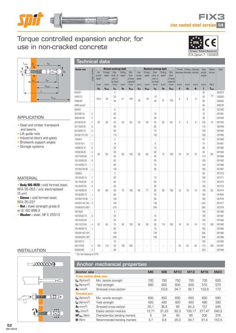
52
Anchor size
Lette
r mar
king Minimum anchorage depth Maximum anchorage depth Thread
diameterDrilling
diameterClearance diameter
Total anchor length
Tighten torque
Codemin.
anchordepth
Embed.depth
Max. thick. of part to be fixed
Drillingdepth
Min. thick.
of base material
max. anchordepth
Embed.depth
Max. thick. of part to be fixed
Drillingdepth
Min. thick.
of base material
(mm) (mm) (mm) (mm) (mm) (mm) (mm) (mm) (mm) (mm) (mm) (mm) (mm) (mm) (Nm)
hef hnom tfix h0 hmin hef hnom tfix h0 hmin d dO df L Tinst
6X45/5* -
25,6 35
5
41 100 35
45
-
51
100
6 6 8
4510
050510
6X55/15* - 20 15 55 050520
6X85/45* - 50 45 85 050530
6X64 percée* - - - 64 056100
8X55/5 - - 5 - 55 057450
8X70/20-10 C 20 10 70 057451
8X90/40-30 E 40 30 90 057452
8X100/50-40 F 30 38 50 50 80 40 48 40 60 80 8 8 9 100 15 057453
8X115/65-55 G 65 55 115 057454
8X130/80-70 H 80 70 130 057455
8X160/110-100 J 110 100 160 057456
10X65/5 -
40 50
5
60 100 50 60
-
70 100 10 10 12
65
30
057460
10X75/15-5 C 15 5 75 057461
10X85/25-15 D 25 15 85 057462
10X95/36-26 E 36 26 95 057463
10X110/50-40 F 50 40 110 057464
10X125/65-55 G 65 55 125 057465
10X140/80-70 I 80 70 140 057466
10X160/100-90 J 100 90 160 057467
12X80/5 - 5 - 80 057470
12X100/25-10 F 25 10 100 057471
12x115/40-25 G 40 25 115 057472
12x125/50-35 H 50 35 125 057473
12X140/65-50 I 50 62 65 75 100 65 77 50 90 130 12 12 14 140 50 057474
12X160/85-70 J 85 70 160 057664
12X180/105-90 L 105 90 180 057576
12X220/145-130 O 145 130 220 057477
12X290/215-200* - 215 200 290 057478
16X100/5 - 5 - 100 057480
16X125/30-15 G 30 15 125 057481
16X150/55-40 I 55 40 150 057482
16X170/75-60 K 65 80 75 95 130 80 95 60 110 160 16 16 18 170 100 057483
16X185/90-75 L 90 75 185 057484
16X235/140-125* - 140 125 235 057485
16X300/205-190* - 205 190 300 057486
20X150/10 - 10 - 150 057490
20X170/30 K 100 113 30 130 200 - - - - - 20 20 22 170 160 057491
20X220/80 0 80 - 220 057492
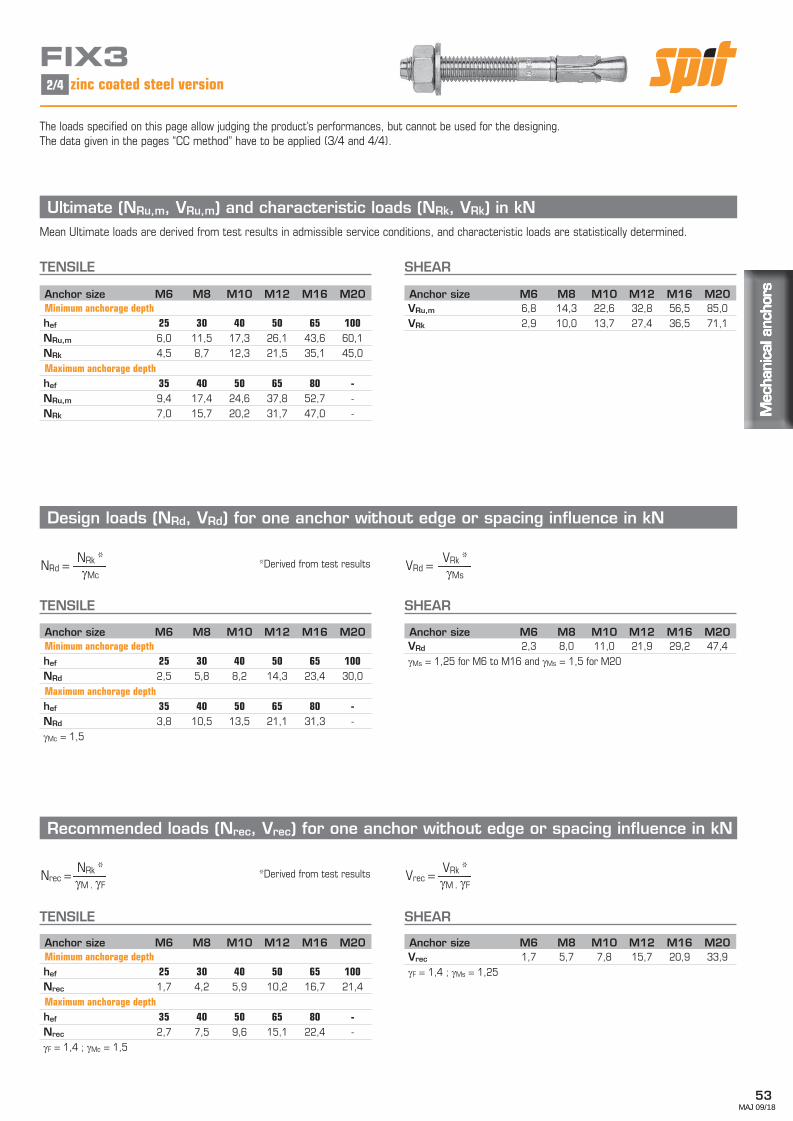
FIX3 zinc coated steel version
d0
heftfix
hmin
h0df
L
d
hnom
Tinst
Torque controlled expansion anchor, for use in non-cracked concrete
INSTALLATION
APPLICATION
Steel and timber frameworkand beams Lift guide rails Industrial doors and gates Brickwork support angles Storage systems
MATERIAL
Body M6-M20 : cold formed steel,NFA 35-053 / zinc electroplated (5 µm) Sleeve : cold formed steel, NFA 35-231 Nut : steel strength grade 6 or 8, ISO 898-2 Washer : steel, NF E 25513
Anchor mechanical properties
Technical dataETA Option 7- 13/0005
* Do not belong to ETA
European Technical Assessment
ETAETA
Anchor size M6 M8 M10 M12 M16 M20Cross-section above conefuk (N/mm2) Min. tensile strength 700 750 750 750 700 600fyk (N/mm2) Yield strength 580 600 600 600 570 570As (mm2) Stressed cross-section - 23,8 34,7 56,1 103,9 172Threaded partfuk (N/mm2) Min. tensile strength 600 650 650 650 600 580fyk (N/mm2) Yield strength 420 420 420 420 480 330As (mm2) Stressed cross-section 20,1 36,6 58 84,3 157 245Wel (mm3) Elastic section modulus 12,71 31,23 62,3 109,17 277,47 540,9M0rk,s (Nm) Characteristic bending moment 9 24 49 85 200 376M (Nm) Recommended bending moment 3,7 9,8 20,0 34,7 81,6 153,5
1/4
MAJ 09/18
53
Mec
hani
cal a
ncho
rsM
echa
nica
l anc
hors
Mec
hani
cal a
ncho
rs
FIX3zinc coated steel version
Ultimate (NRu,m, VRu,m) and characteristic loads (NRk, VRk) in kN Mean Ultimate loads are derived from test results in admissible service conditions, and characteristic loads are statistically determined.
TENSILE SHEAR
Design loads (NRd, VRd) for one anchor without edge or spacing influence in kN
TENSILE SHEAR
Recommended loads (Nrec, Vrec) for one anchor without edge or spacing influence in kN
TENSILE SHEAR
Anchor size M6 M8 M10 M12 M16 M20Minimum anchorage depthhef 25 30 40 50 65 100NRd 2,5 5,8 8,2 14,3 23,4 30,0Maximum anchorage depthhef 35 40 50 65 80 -NRd 3,8 10,5 13,5 21,1 31,3 -γMc = 1,5
Anchor size M6 M8 M10 M12 M16 M20VRu,m 6,8 14,3 22,6 32,8 56,5 85,0VRk 2,9 10,0 13,7 27,4 36,5 71,1
Anchor size M6 M8 M10 M12 M16 M20Minimum anchorage depthhef 25 30 40 50 65 100NRu,m 6,0 11,5 17,3 26,1 43,6 60,1NRk 4,5 8,7 12,3 21,5 35,1 45,0Maximum anchorage depthhef 35 40 50 65 80 -NRu,m 9,4 17,4 24,6 37,8 52,7 -NRk 7,0 15,7 20,2 31,7 47,0 -
Anchor size M6 M8 M10 M12 M16 M20Minimum anchorage depthhef 25 30 40 50 65 100Nrec 1,7 4,2 5,9 10,2 16,7 21,4Maximum anchorage depthhef 35 40 50 65 80 -Nrec 2,7 7,5 9,6 15,1 22,4 -γF = 1,4 ; γMc = 1,5
Anchor size M6 M8 M10 M12 M16 M20VRd 2,3 8,0 11,0 21,9 29,2 47,4γMs = 1,25 for M6 to M16 and γMs = 1,5 for M20
Anchor size M6 M8 M10 M12 M16 M20Vrec 1,7 5,7 7,8 15,7 20,9 33,9γF = 1,4 ; γMs = 1,25
2/4
*Derived from test resultsγMc
NRk *NRd = γMs
VRk *VRd =
γM . γF
NRk *Nrec = γM . γF
VRk *Vrec =*Derived from test results
The loads specified on this page allow judging the product’s performances, but cannot be used for the designing.The data given in the pages “CC method” have to be applied (3/4 and 4/4).
MAJ 09/18

54
FIX3 zinc coated steel version
SPIT CC Method (values issued from ETA)TENSILE in kN SHEAR in kN
¬ Pull-out resistanceN
¬ Concrete cone resistanceN
¬ Pryout failureV
¬ Steel resistance
N
¬ Concrete edge resistance V
fb INFLUENCE OF CONCRETE
¬ Steel resistanceV
NRd = min(NRd,p ; NRd,c ; NRd,s)βN = NSd / NRd ≤ 1
VRd = min(VRd,c ; VRd,cp ; VRd,s)βV = VSd / VRd ≤ 1
βN + βV ≤ 1,2
β
V
90˚
180˚ 0˚
c
90° ≤
β ≤ 180° 60°≤ β ≤90°
0°≤ β ≤60°
N0Rd,p Design pull-out resistanceAnchor size M8 M10 M12 M16 M20Minimum anchorage depthhef 30 40 50 65 100N0Rd,p (C20/25) 5,0 - - - -Maximum anchorage depthhef 40 50 65 80 -N0Rd,p (C20/25) - - - - -γMc = 1,5
Concrete class fb Concrete class fbC25/30 1,1 C40/50 1,41C30/37 1,22 C45/55 1,48C35/45 1,34 C50/60 1,55
V0Rd,c Design concrete edge resistance at minimum edge distance (Cmin)
Anchor size M8 M10 M12 M16 M20Minimum anchorage depthhef 30 40 50 65 100Cmin 50 65 100 100 100Smin 40 50 100 100 160V0Rd,c (C20/25) 2,7 4,6 9,7 11,1 13,0Maximum anchorage depthhef 40 50 65 80 -Cmin 55 65 70 105 -Smin 45 60 70 90 -V0Rd,c (C20/25) 3,3 4,8 6,0 12,5 -γMc = 1,5
V0Rd,cp Design pryout resistanceAnchor size M8 M10 M12 M16 M20Minimum anchorage depthhef 30 40 50 65 100V0Rd,cp (C20/25) 5,5 8,5 11,9 35,2 67,2Maximum anchorage depthhef 40 50 65 80 -V0Rd,cp (C20/25) 8,5 11,9 35,2 48,0 -γMcp = 1,5
VRd,s Steel design shear resistanceAnchor size M8 M10 M12 M16 M20VRd,s 8,0 11,0 21,9 29,2 40,7γMs = 1,25 for M8 to M16 and γMs = 1,5 for M20
Angle β [°] fβ,V
0 to 55 160 1,170 1,280 1,590 to 180 2
N0Rd,c Design cone resistanceAnchor size M8 M10 M12 M16 M20Minimum anchorage depthhef 30 40 50 65 100N0Rd,c (C20/25) 5,5 8,5 11,9 17,6 33,6Maximum anchorage depthhef 40 50 65 80 -N0Rd,c (C20/25) 8,5 11,9 17,6 24,0 -γMc = 1,5
VRd,s Steel design tensile resistanceAnchor size M8 M10 M12 M16 M20VRd,s 11,9 17,3 28,1 48,5 66,1γMs = 1,5 for M8 to M16 and γMs = 1,5 for M20
3/4
NRd,p = N0Rd,p . fb
NRd,c = N0Rd,c . fb . Ψs . Ψc,N
VRd,c = V0Rd,c . fb . fβ,V . ΨS-C,V
VRd,cp = V0Rd,cp . fb . Ψs . Ψc,N
fβ,V INFLUENCE OF SHEAR LOADING DIRECTION
MAJ 09/18

55
Mec
hani
cal a
ncho
rsM
echa
nica
l anc
hors
Mec
hani
cal a
ncho
rs
FIX3zinc coated steel version
Ψs INFLUENCE OF SPACING FOR CONCRETE CONE RESISTANCE IN TENSILE LOAD
Ψc,N INFLUENCE OF EDGE FOR CONCRETE CONE RESISTANCE IN TENSILE LOAD
Ψs-c,V INFLUENCE OF SPACING AND EDGE DISTANCE FOR CONCRETE EDGE RESISTANCE IN SHEAR LOAD
¬ For 2 anchors fastening
¬ For 3 anchors fastening and more
N
c
s
N
V
h>1,5.c
s
V
h>1,5.c
¬ For single anchor fastening
SPIT CC Method (values issued from ETA)
s1
V
s2 s3
sn-1
h>1,5.c
Reduction factor Ψs-c,VNon-cracked concrete
1,0 1,2 1,4 1,6 1,8 2,0 2,2 2,4 2,6 2,8 3,0 3,2
1,0 0,67 0,84 1,03 1,22 1,43 1,65 1,88 2,12 2,36 2,62 2,89 3,161,5 0,75 0,93 1,12 1,33 1,54 1,77 2,00 2,25 2,50 2,76 3,03 3,312,0 0,83 1,02 1,22 1,43 1,65 1,89 2,12 2,38 2,63 2,90 3,18 3,462,5 0,92 1,11 1,32 1,54 1,77 2,00 2,25 2,50 2,77 3,04 3,32 3,613,0 1,00 1,20 1,42 1,64 1,88 2,12 2,37 2,63 2,90 3,18 3,46 3,763,5 1,30 1,52 1,75 1,99 2,24 2,50 2,76 3,04 3,32 3,61 3,914,0 1,62 1,86 2,10 2,36 2,62 2,89 3,17 3,46 3,75 4,054,5 1,96 2,21 2,47 2,74 3,02 3,31 3,60 3,90 4,205,0 2,33 2,59 2,87 3,15 3,44 3,74 4,04 4,355,5 2,71 2,99 3,28 3,71 4,02 4,33 4,656,0 2,83 3,11 3,41 3,71 4,02 4,33 4,65
Cmin
C
Cmin
S
Reduction factor Ψs-c,VNon-cracked concrete
1,0 1,2 1,4 1,6 1,8 2,0 2,2 2,4 2,6 2,8 3,0 3,2
Ψs-c,V 1,00 1,31 1,66 2,02 2,41 2,83 3,26 3,72 4,19 4,69 5,20 5,72
Cmin
C
SPACING S Reduction factor ΨsMaximum anchorage depth
Anchor size M8 M10 M12 M1645 0,6960 0,75 0,7070 0,79 0,73 0,6890 0,88 0,80 0,73 0,69100 0,92 0,83 0,76 0,71120 1,00 0,90 0,81 0,75150 1,00 0,88 0,81195 1,00 0,91220 0,96240 1,00
SPACING S Reduction factor ΨsMinimum anchorage depth
Anchor size M8 M10 M12 M16 M2040 0,7250 0,78 0,7165 0,86 0,7790 1,00 0,88100 0,92 0,83 0,76120 1,00 0,90 0,81130 0,93 0,83 0,72150 1,00 0,88 0.83180 0,96 0,90195 1,00 0,93225 1,00
EDGE CReduction factor Ψc,N
Maximum anchorage depth
Anchor size M8 M10 M12 M1655 0,9360 1,0065 0,8970 0,94 0,7875 1,00 0,82100 1,00105 0,90110 0,93120 1,00
EDGE CReduction factor Ψc,N
Minimum anchorage depth
Anchor size M8 M10 M12 M16 M2050 1,0065 1,00100 1,00100 1,00120 1,00
4/4
Ψs = 0,5 + s
6.hef= 0,5 +
Ψc,N = 0,23 + 0,51 . c
hef= 0,23 + 0,51 .
Ψs-c,V = c
.√ c
cmin cmin=
Ψs-c,V = 3.c + s
.√ c
6.cmin cmin
Ψs-c,V = 3.c + s1 + s2 + s3 +....+ sn-1 .√
c 3.n.cmin cmin
smin < s < scr,N
scr,N = 3.hef
ΨS must be used for each spacing influenced the anchors group
cmin < c < ccr,N
ccr,N = 1,5.hef
Ψc,N must be used for each distance influenced the anchors group.
MAJ 09/18