particular technical specificationsmca.gov.md/upload/procurment/cisra/ifb4nistru/ifb-pp6... · web...
TRANSCRIPT

BIDDING DOCUMENTSIFB #PP6/THVAP/W/CB/03
CONSTRUCTION WORKS FOR THE REHABILITATION OF CENTRALIZED IRRIGATION SYSTEMS ALONG NISTRU RIVER
Section IX TECHNICAL SPECIFICATIONS
LOT #2 – CIS ‘COSNITA’
PARTICULAR TECHNICAL SPECIFICATIONS
_________________________________________________________________________________

Rehabilitation Works on CISs along Nistru River IFB #PP6/THVAP/W/CB/03 Millennium Challenge Account – Moldova
PARTICULAR SPECIFICATIONTABLE OF CONTENTS
1 PARTICULAR TECHNICAL SPECIFICATIONS............................................................6
2 SCOPE OF WORKS..............................................................................................................6
2.1 INTRODUCTION.........................................................................................................62.2 LOCATION OF WORKS.....................................................................................................62.3 SHORT DESCRIPTION OF THE WORKS...........................................................................72.4 SITE INFORMATION.........................................................................................................9
2.4.1 Limits of the sites...................................................................................................92.4.2 Access to sites........................................................................................................92.4.3 Topography............................................................................................................92.4.4 Geology................................................................................................................102.4.5 Seismic activity....................................................................................................102.4.6 Temperature.........................................................................................................102.4.7 Rainfall.................................................................................................................112.4.8 Definitions............................................................................................................112.4.9 Submission by the Contractor..............................................................................12
3 PIPELINE AND PIPEWORK.............................................................................................14
3.1 PIPE’S SUMMARY..........................................................................................................143.2 STEEL PIPES..................................................................................................................16
3.2.1 General................................................................................................................163.2.2 Coating & Lining of underground pipe and Fittings...........................................17
3.2.2.1 Preparation of Metal Surfaces..........................................................................183.2.2.2 External Polyethylene Coating for Pipes (PE).................................................183.2.2.3 Thickness of external Polyethylene Coating for Pipes (PE)............................193.2.2.4 Composition and Application of Internal Epoxy Lining.................................203.2.2.5 Dry thickness Internal Epoxy Lining...............................................................213.2.2.6 Inspection.........................................................................................................213.2.2.7 Field Completion of the Internal Epoxy Lining at Welded Pipe Joints...........223.2.2.8 Field Completion of the External Coating at Welded Pipe Joints...................25
3.2.3 Handling Transportation and Storage of Coated and Lined Steel Pipes and Fittings.............................................................................................................................25
3.3 HDPE PIPE...................................................................................................................263.4 CROSSING UNDER ROADS AND RAILWAY TRACKS......................................26
3.4.1 General................................................................................................................263.4.2 Detailed Design...................................................................................................273.4.3 Site Investigation..................................................................................................283.4.4 Records................................................................................................................28
3.5 FITTINGS....................................................................................................................283.5.1 Steel elbow...........................................................................................................283.5.2 HDPE elbows.......................................................................................................283.5.3 HDPE reduction..................................................................................................29
_________________________________________________________________________________Section IX. Specifications – Lot #2 / CIS ‘Cosnita’ i

Rehabilitation Works on CISs along Nistru River IFB #PP6/THVAP/W/CB/03 Millennium Challenge Account – Moldova
3.5.4 Steel flanged reduction........................................................................................293.5.5 HDPE Tee piece...................................................................................................293.5.6 HDPE flange adaptor..........................................................................................293.5.7 Steel flanged Tee/Cross.......................................................................................293.5.8 Steel flange...........................................................................................................303.5.9 Special flanged HDPE T-piece............................................................................303.5.10 Special flanged pipes.......................................................................................303.5.11 Double flanged steel pipes for hydrant risers..................................................303.5.12 Special hydrant valve.......................................................................................303.5.13 Hydrant............................................................................................................313.5.14 Air valves.........................................................................................................313.5.15 Washout...........................................................................................................31
3.6 VALVES........................................................................................................................323.6.1 Valves - general...................................................................................................323.6.2 Setting of Valves, etc............................................................................................353.6.3 Gaps for Valves, hydrants, Air valves,.................................................................36
4 DETAILED ELECTROMECHANICAL AND ELECTRICAL WORKS FOR PUMPING STATION SP-1.................................................................................................37
4.1 INTRODUCTION.............................................................................................................374.1.1 General description of the SP-1 pumping station................................................374.1.2 General principle of operation............................................................................374.1.3 Scope of Work......................................................................................................38
4.2 HYDRO- AND ELECTRO-MECHANICAL EQUIPMENT.......................................................394.2.1 Intake structures..................................................................................................394.2.2 Pumping units......................................................................................................394.2.3 Vacuum system.....................................................................................................414.2.4 Dewatering system...............................................................................................424.2.5 Water hammer protection system........................................................................424.2.6 Pipes and fittings.................................................................................................434.2.7 Valves...................................................................................................................434.2.8 Overhead travelling crane...................................................................................444.2.9 Ventilation............................................................................................................44
4.3 ELECTRICAL EQUIPMENT..............................................................................................454.3.1 Power supply........................................................................................................454.3.2 Power requirements.............................................................................................454.3.3 Low voltage electrical switch- and control gears................................................454.3.4 General incoming and protection switch gear....................................................464.3.5 Motor starter switch gear with Variable Frequency Drive.................................474.3.6 Switch- and control gear for ancillaries..............................................................484.3.7 Command, automation and remote control switch- and control gear.................504.3.8 Secondary incoming and protection switch gear common with SPP-2...............514.3.9 Secondary switch- and control gear for ancillaries............................................514.3.10 Remote control panels for the main pumps.....................................................524.3.11 Remote control panel for the vacuum system..................................................52
_________________________________________________________________________________Section IX. Specifications – Lot #2 / CIS ‘Cosnita’ ii

Rehabilitation Works on CISs along Nistru River IFB #PP6/THVAP/W/CB/03 Millennium Challenge Account – Moldova
4.3.12 Remote control panel for the drainage pumps.................................................534.4 AUTOMATION AND SCADA SYSTEM...........................................................................53
4.4.1 Instrumentation and metering..............................................................................534.4.2 Automation and Control philosophy....................................................................55
4.4.2.1 Operating modes..............................................................................................554.4.2.2 Control philosophy..........................................................................................554.4.2.3 Processing failure and alarms..........................................................................594.4.2.4 Processing data and curves..............................................................................60
4.4.3 PLC input /output.................................................................................................614.4.4 Supervisory Control and Data Acquisition system (SCADA)..............................65
4.4.4.1 Structure of the system....................................................................................654.4.4.2 Remote Terminal Units....................................................................................664.4.4.3 Remote controlled parameters.........................................................................66
5 DETAILED ELECTROMECHANICAL AND ELECTRICAL WORKS FOR PUMPING STATION SP-2.................................................................................................68
5.1 INTRODUCTION.............................................................................................................685.1.1 General description of the SP-2 pumping station................................................685.1.2 General principle of operation............................................................................685.1.3 Scope of Work......................................................................................................69
5.2 HYDRO- AND ELECTRO-MECHANICAL EQUIPMENT.......................................................705.2.1 Intake structures..................................................................................................705.2.2 Pumping units......................................................................................................715.2.3 Vacuum system.....................................................................................................735.2.4 Dewatering system...............................................................................................745.2.5 Water hammer protection system........................................................................745.2.6 Pipes and fittings.................................................................................................755.2.7 Valves...................................................................................................................755.2.8 Overhead travelling crane...................................................................................765.2.9 Ventilation............................................................................................................77
5.3 ELECTRICAL EQUIPMENT..............................................................................................775.3.1 Power supply........................................................................................................775.3.2 Power requirements.............................................................................................775.3.3 Low voltage electrical switch- and control gears................................................785.3.4 General incoming and protection switch gear....................................................785.3.5 Motor starter switch gear with Variable Frequency Drive.................................795.3.6 Switch- and control gear for ancillaries..............................................................805.3.7 Command, automation and remote control switch- and control gear.................825.3.8 Secondary incoming and protection switch gear common with SPP-2...............845.3.9 Secondary switch- and control gear for ancillaries............................................845.3.10 Remote control panels for the main pumps.....................................................845.3.11 Remote control panel for the vacuum system..................................................855.3.12 Remote control panel for the drainage pumps.................................................855.3.13 Remote control panel for the water hammer protection system......................86
5.4 AUTOMATION AND SCADA SYSTEM...........................................................................86
_________________________________________________________________________________Section IX. Specifications – Lot #2 / CIS ‘Cosnita’ iii

Rehabilitation Works on CISs along Nistru River IFB #PP6/THVAP/W/CB/03 Millennium Challenge Account – Moldova
5.4.1 Instrumentation and metering..............................................................................865.4.2 Automation and Control philosophy....................................................................88
5.4.2.1 Operating modes..............................................................................................885.4.2.2 Control philosophy..........................................................................................895.4.2.3 Processing failure and alarms..........................................................................935.4.2.4 Processing data and curves..............................................................................94
5.4.3 PLC input /output.................................................................................................965.4.4 Supervisory Control and Data Acquisition system (SCADA)............................100
5.4.4.1 Structure of the system..................................................................................1005.4.4.2 Remote Terminal Units..................................................................................1015.4.4.3 Remote controlled parameters.......................................................................101
6 DETAILED ELECTROMECHANICAL AND ELECTRICAL WORKS FOR PUMPING STATION SP-3A.............................................................................................102
6.1 INTRODUCTION...........................................................................................................1026.1.1 General description of the SP-3A pumping station...........................................1026.1.2 General principle of operation..........................................................................1026.1.3 Scope of Work....................................................................................................103
6.2 HYDRO- AND ELECTRO-MECHANICAL EQUIPMENT.....................................................1046.2.1 Intake structures................................................................................................1046.2.2 Pumping units....................................................................................................1056.2.3 Vacuum system...................................................................................................1066.2.4 Dewatering system.............................................................................................1076.2.5 Water hammer protection system......................................................................1086.2.6 Pipes and fittings...............................................................................................1086.2.7 Valves.................................................................................................................1096.2.8 Overhead travelling crane.................................................................................1106.2.9 Ventilation..........................................................................................................110
6.3 ELECTRICAL EQUIPMENT............................................................................................1116.3.1 Power supply......................................................................................................1116.3.2 Power requirements...........................................................................................1116.3.3 Low voltage electrical switch- and control gears..............................................1116.3.4 General incoming and protection switch gear..................................................1126.3.5 Motor starter switch gear with Variable Frequency Drive...............................1136.3.6 Switch- and control gear for ancillaries............................................................1146.3.7 Command, automation and remote control switch- and control gear...............1166.3.8 Secondary incoming and protection switch gear...............................................1176.3.9 Secondary switch- and control gear for ancillaries..........................................1176.3.10 Remote control panels for the main pumps...................................................1186.3.11 Remote control panel for the vacuum system................................................1186.3.12 Remote control panel for the drainage pumps...............................................1196.3.13 Remote control panel for the water hammer protection system....................119
6.4 AUTOMATION AND SCADA SYSTEM.........................................................................1206.4.1 Instrumentation and metering............................................................................1206.4.2 Automation and Control philosophy..................................................................122
_________________________________________________________________________________Section IX. Specifications – Lot #2 / CIS ‘Cosnita’ iv

Rehabilitation Works on CISs along Nistru River IFB #PP6/THVAP/W/CB/03 Millennium Challenge Account – Moldova
6.4.2.1 Operating modes............................................................................................1226.4.2.2 Control philosophy........................................................................................1226.4.2.3 Processing failure and alarms........................................................................1276.4.2.4 Processing data and curves............................................................................128
6.4.3 PLC input /output...............................................................................................1296.4.4 Supervisory Control and Data Acquisition system (SCADA)............................133
6.4.4.1 Structure of the system..................................................................................1336.4.4.2 Remote Terminal Units..................................................................................1346.4.4.3 Remote controlled parameters.......................................................................135
7 DETAILED ELECTROMECHANICAL AND ELECTRICAL WORKS FOR PUMPING STATION SP-4...............................................................................................136
7.1 INTRODUCTION...........................................................................................................1367.1.1 General description of the SP-4 pumping station..............................................1367.1.2 General principle of operation..........................................................................1367.1.3 Scope of Work....................................................................................................137
7.2 HYDRO- AND ELECTRO-MECHANICAL EQUIPMENT.....................................................1387.2.1 Intake structures................................................................................................1387.2.2 Pumping units....................................................................................................139
7.2.2.1 Pumping units for SP-4A...............................................................................1397.2.2.2 Pumping units for SP-4B...............................................................................141
7.2.3 Vacuum system...................................................................................................1437.2.4 Dewatering system.............................................................................................1447.2.5 Water hammer protection system......................................................................144
7.2.5.1 Water hammer protection system for SP-4A.................................................1447.2.5.2 Water hammer protection system for SP-4B.................................................145
7.2.6 Pipes and fittings...............................................................................................1457.2.6.1 Pipes and fittings for SP-4A..........................................................................1467.2.6.2 Pipes and fittings for SP-4B...........................................................................1467.2.6.3 Ancillary Pipes and fittings............................................................................147
7.2.7 Valves.................................................................................................................1477.2.7.1 Valves for SP-4A...........................................................................................1477.2.7.2 Valves for SP-4B...........................................................................................1477.2.7.3 Ancillary valves.............................................................................................148
7.2.8 Overhead travelling crane.................................................................................1487.2.9 Ventilation..........................................................................................................149
7.2.9.1 Ventilation for SP-4A....................................................................................1497.2.9.2 Ventilation for SP-4B....................................................................................149
7.3 ELECTRICAL EQUIPMENT............................................................................................1507.3.1 Power supply......................................................................................................1507.3.2 Power requirements...........................................................................................1507.3.3 Low voltage electrical switch- and control gears..............................................1507.3.4 General incoming and protection switch gear..................................................1517.3.5 Motor starter switch gear with Variable Frequency Drive for SP-4A..............1527.3.6 Motor starter switch gear with Variable Frequency Drive for SP-4B..............153
_________________________________________________________________________________Section IX. Specifications – Lot #2 / CIS ‘Cosnita’ v

Rehabilitation Works on CISs along Nistru River IFB #PP6/THVAP/W/CB/03 Millennium Challenge Account – Moldova
7.3.7 Switch- and control gear for ancillaries............................................................1547.3.8 Command, automation and remote control switch- and control gear...............1567.3.9 Secondary incoming and protection switch gear...............................................1587.3.10 Secondary switch- and control gear for ancillaries......................................1587.3.11 Remote control panels for the main pumps...................................................1587.3.12 Remote control panel for the vacuum system................................................1597.3.13 Remote control panel for the drainage pumps...............................................1607.3.14 Remote control panel for the water hammer protection system....................160
7.4 AUTOMATION AND SCADA SYSTEM.........................................................................1617.4.1 Instrumentation and metering............................................................................1617.4.2 Automation and Control philosophy..................................................................163
7.4.2.1 Operating modes............................................................................................1637.4.2.2 Control philosophy........................................................................................1637.4.2.3 Processing failure and alarms........................................................................1687.4.2.4 Processing data and curves............................................................................169
7.4.3 PLC input /output...............................................................................................1707.4.4 Supervisory Control And Data Acquisition system (SCADA)...........................174
7.4.4.1 Structure of the system..................................................................................1747.4.4.2 Remote Terminal Units..................................................................................1757.4.4.3 Remote controlled parameters.......................................................................176
8 SPARE PARTS AND TOOLS...........................................................................................177
8.1 SPARE PARTS..........................................................................................................1778.1.1 Spare parts for pipe network.............................................................................1778.1.2 Spare parts for pumping station........................................................................177
8.2 TOOLS.......................................................................................................................179
9 ARCHITECTURAL/STRUCTURALWORKS IN THE PUMPING STATION.........181
9.1 NEW PUMPING STATIONS...................................................................................1819.2 REHABILITATION WORKS..................................................................................1819.2.1 FLOORING...............................................................................................................1819.2.2 FOUNDATIONS FOR PUMPS, MOTORS AND TANKS...................................................1819.2.3 WALL REPAIRING...................................................................................................1829.2.4 DAMAGED CONCRETE REPAIRING...........................................................................1829.2.5 REINFORCEMENT OF THE BUILDING STRUCTURE....................................................1829.2.6 JOINTS FILLING.......................................................................................................1839.2.7 WATERPROOFING...................................................................................................1839.2.8 ROOF REPAIR AND INSULATION..............................................................................183
_________________________________________________________________________________Section IX. Specifications – Lot #2 / CIS ‘Cosnita’ vi

Rehabilitation Works on CISs along Nistru River IFB #PP6/THVAP/W/CB/03 Millennium Challenge Account – Moldova
1 PARTICULAR TECHNICAL SPECIFICATIONS
The Particular Technical Specifications (PTS) cover only those items that are specific to a particular scheme and includes:
The scope of work Site information Pipe’s detailed specification Mechanical and electrical works in terms of specific performance and duty
characteristics of pumping plant, motors and switchgear
The Particular Specification should be read in conjunction with the General Specification, which includes specifications and standards applicable to all work, materials, plant and equipment which are common to all schemes.
2 SCOPE OF WORKS
2.1 INTRODUCTION
The objectives of the contract is the construction, testing, commissioning and subsequent training of operation and maintenance staff in respect of the Rehabilitation of the Centralized Irrigation System in Cosnita (2483Ha). The Contract includes the furnishing of all labour, plant, equipment and materials required to complete the entire works, pre-commissioning, commissioning, testing, reinstatement of the Sites, preparation of working, shop and as-built drawings, training of operation and maintenance staff and the rectification of defects during the maintenance period specified in the Contract.
2.2 LOCATION OF WORKS
The irrigation system Cosnita is located in Dubasari district on the left bank of Nistru River. The total irrigable area is about 2483 hectares and consists of the following four sectors laying between villages Cosnita and Pirita inside of an almost circular meander of the Nistru River:
The first sector (called sector SP-1) of 1043 Ha is served by the pressure pumping station SP-1 taking water from Nistru River and delivering it directly to the pipe network.
The second sector (called sector SP-2), of 365Ha is served by the pumping station SP-2 which takes water from Nistru River and delivers it directly to the pipe network. The irrigated land is situated on the left side of a sharp bend of River Nistru, to the south-west of the village Pirita.
_________________________________________________________________________________Section IX. Specifications – Lot #2 / CIS ‘Cosnita’ 7

Rehabilitation Works on CISs along Nistru River IFB #PP6/THVAP/W/CB/03 Millennium Challenge Account – Moldova
The third sector (called sector SP-3, S-1), of 583Ha is served by the supply pumping stations SP-3 which takes water from Nistru River and delivers it to the pressure pumping station S-1 which, in turn, delivers the water to the pipe network. The irrigated area is located on the left side of the steep curve of River Nistru, to the south-west of the village Cosnita
The forth sector (called sector SP-4), comprising about 492Ha is served by the pump station SP-4.
The irrigation network has a total length of about 85 km and consists of distribution pipelines mainly made of asbestos-cement pipe sections of diameters variable between 160 and 400 mm and nominal pressure 8 bar.
2.3 SHORT DESCRIPTION OF THE WORKS
The works comprise:
The construction of a new pressure pumping station SP-1 close to the existing one including the river intake, located on the left bank of the Nistru River, including:
o Construction of the intake works, including installation of new fish protection devices and ice protection measures;
o Construction of a new building;o Supply and installation of new pumps, motors, associated pipe-work and
electric switch gear; o Landscaping, installing the fence and install water drainage around pumping
station SP-1.
The construction of some 31.3 km of a new pipe network supplied by SP-1 and comprising:
o 2389 m of steel pipeline of 800 mm diameter;o 2511 m of steel pipeline of 500 mm diameter;o 626 m of HDPE pipeline of 400 mm diameter;o 943 m of HDPE pipeline of 355 mm diameter;o 5940 m of HDPE pipeline of 250 mm diameter;o 1808 m of HDPE pipeline of 225 mm diameter;o 8659 m of HDPE pipeline of 200 mm diameter;o 1517 m of HDPE pipeline of 180 mm diameter;o 7392 m of HDPE pipeline of 160 mm diameter;o all necessary fittings, including new irrigation hydrants.
The rehabilitation of the river intake and lifting pumping stations SP-2, located on the left bank of the Nistru River, including:
o replacing the intake works, including installation of new fish protection devices and ice protection measures;
_________________________________________________________________________________Section IX. Specifications – Lot #2 / CIS ‘Cosnita’ 8

Rehabilitation Works on CISs along Nistru River IFB #PP6/THVAP/W/CB/03 Millennium Challenge Account – Moldova
o refurbishing the existing building and strengthening the structures to meet prevailing earthquake legislation including extension of the building with a new technical room for the electrical switch gears;
o supply and installation of new pumps, motors, associated pipe-work and electric switch gear;
o Landscaping, installing the fence and install water drainage around pumping station SP-2.
The construction of some 12.3 km of a new pipe network supplied by SP-2 and comprising:
o 5 m of steel pipeline of 500 mm diameter;o 871 m of steel pipeline of 400 mm diameter;o 648 m of HDPE pipeline of 355 mm diameter;o 833 m of HDPE pipeline of 315 mm diameter;o 1340 m of HDPE pipeline of 280 mm diameter;o 2094 m of HDPE pipeline of 250 mm diameter;o 993 m of HDPE pipeline of 225 mm diameter;o 4673 m of HDPE pipeline of 200 mm diameter;o 858 m of HDPE pipeline of 160 mm diameter;o all necessary fittings, including new irrigation hydrants.
The construction of a new pressure pumping station SP-3 close to the existing ones including the river intake:
o Construction of the intake works, including installation of new fish protection devices and ice protection measures;
o Construction of a new building;o Supply and installation of new pumps, motors, associated pipe-work and
electric switch gear; o Landscaping, installing the fence and install water drainage around pumping
station SP-1.
The construction of some 23.6 km of a new pipe network supplied by SP-3 and comprising:
o 1860 m of steel pipeline of 800 mm diameter;o 904 m of steel pipeline of 700 mm diameter;o 844 m of steel pipeline of 600 mm diameter;o 624 m of steel pipeline of 500 mm diameter;o 308 m of HDPE pipeline of 400 mm diameter;o 645 m of HDPE pipeline of 355 mm diameter;o 626 m of HDPE pipeline of 280 mm diameter;o 972 m of HDPE pipeline of 250 mm diameter;o 3326 m of HDPE pipeline of 225 mm diameter;o 13550 m of HDPE pipeline of 160 mm diameter;
_________________________________________________________________________________Section IX. Specifications – Lot #2 / CIS ‘Cosnita’ 9

Rehabilitation Works on CISs along Nistru River IFB #PP6/THVAP/W/CB/03 Millennium Challenge Account – Moldova
o all necessary fittings, including new irrigation hydrants.
The rehabilitation of the pressure pumping stations SP-4, located on the left bank of the Nistru River, including:
o replacing the intake works, including installation of new fish protection devices and ice protection measures;
o refurbishing the existing building and strengthening the structures to meet prevailing earthquake legislation including extension of the building with a new technical room for the electrical switch gears;
o supply and installation of new pumps, motors, associated pipe-work and electric switch gear;
o Landscaping, installing the fence and install water drainage around pumping station SP-4.
The construction of some 18.4 km of a new pipe network supplied by SP-4 and comprising:
o 1970 m of steel pipeline of 500 mm diameter;o 297 m of HDPE pipeline of 400 mm diameter;o 734 m of HDPE pipeline of 315 mm diameter;o 1910 m of HDPE pipeline of 280 mm diameter;o 4071 m of HDPE pipeline of 225 mm diameter;o 6588 m of HDPE pipeline of 200 mm diameter;o 1639 m of HDPE pipeline of 180 mm diameter;o 1174 m of HDPE pipeline of 160 mm diameter;o all necessary fittings, including new irrigation hydrants.
2.4 SITE INFORMATION
2.4.1 Limits of the sites
For the purpose of carrying out the Works the Contractor shall limit his installations and operations to the defined working areas described on the Contract drawings. The Contractor shall be responsible for complying with all relevant bylaws of related Municipalities, Utilities and Authorities and obtaining all necessary permits and licenses.
2.4.2 Access to sites
The projects area is located on left bank of the Nistru River. Access to the river intakes and pumping stations is via several non paved roads. Access to the pipelines is either via the working easement along the existing pipelines or via the farm tracks which intersect the area.
2.4.3 Topography
_________________________________________________________________________________Section IX. Specifications – Lot #2 / CIS ‘Cosnita’ 10

Rehabilitation Works on CISs along Nistru River IFB #PP6/THVAP/W/CB/03 Millennium Challenge Account – Moldova
The Cosnita irrigation areas are mostly on large terraces, with slopes not exceeding 8%. The absolute elevations of the relief vary within 13.00 - 125.00 m Baltic System.
2.4.4 Geology
Under geomorphologic zoning, this territory is located on the Dniester River terrace plain and is confined to the Middle-Dniester sub-district being zone bordering with the Trans-Dniester swell-like upland. The Middle-Dniester sub-district is represented almost completely by the late Pliocene terraces of the Dniester River.
This region is featured by prevailing valley-terrace shapes of relief dissected by the Pleistocene-Holocene age and modern erosion processes into the series of smaller areas.Peculiarity of the territory consists in the dense network of well-developed gully and ravine-gully systems featured by vast morphologic diversity. Ravine-gully watersheds will define strength features of terrain, while gully ones will form the slope of runoff. In geomorphologic aspect, the territory is referred to several geomorphologic elements: the Dniester River floodplain, adjacent slopes and watersheds (multiple terraces of the Dniester River). On individual areas, slopes are affected by erosion processes; ravine depth achieves 7-10 m. Right bank of the Dniester River is abrupt and bold (more than 5 meters in some sections). Within boundaries of the area, there are deposits of middle and upper Pliocene represented by sands with gravel lenses (rare by clays) at the bottom and conglomerates, pebble gravel, sands, loams and fossil soils at the top.
The information Document attached to the Tender Documents contains Surveys from a 2012 investigation in the project areas. The studies indicate that in general the ground water table stands at some 8-10 meters below ground level except in proximity to the main intake pumping station SPP-1 and SPP-2, where the level tends to equate to the prevailing river level. However, the Contractor is required to undertake his own investigations and to satisfy himself as the geological conditions in the project area in so far as these may affect the Works.
2.4.5 Seismic activity
The current and official documents concerning seismic design parameters of Moldova are included in the Decree #25 dated 23 December 2009 of the Ministry of Construction and Regional Development "Approval of the Seismic Regions in the Republic of Moldova at scale 1:400,000". The Seismic Regionalization Map shows that all the Cosnita project area is included in the “7-degree seismic zone”.
2.4.6 Temperature
The temperature regime is temperate continental climate, characterized by hot summers and cold winters. Tables 1.1and 1.2 shows the average monthly temperatures for the project area sites.
_________________________________________________________________________________Section IX. Specifications – Lot #2 / CIS ‘Cosnita’ 11

Rehabilitation Works on CISs along Nistru River IFB #PP6/THVAP/W/CB/03 Millennium Challenge Account – Moldova
Table 1.1-Montly average air temperaturesDistricts Jan Feb Mar Apr May Jun Jul Aug Sep Oct Nov Dec YearCosnita -3,3 -2,0 2,7 9,8 16,0 19,4 21,4 20,8 16,0 10,1 4,0 -0,8 9,5
_________________________________________________________________________________Section IX. Specifications – Lot #2 / CIS ‘Cosnita’ 12

Rehabilitation Works on CISs along Nistru River IFB #PP6/THVAP/W/CB/03 Millennium Challenge Account – Moldova
Table 1.2-Minimum air temperaturesDistricts Jan Feb Mar Apr Ma
yJun Jul Aug Sep Oct Nov Dec Year
Cosnita -29,8 -31,5 -23,0 -8,5 -1,8 3,6 7,8 5,5 -2,4 10,8 -21,7 -22,4 -31,5
_________________________________________________________________________________Section IX. Specifications – Lot #2 / CIS ‘Cosnita’ 13

Rehabilitation Works on CISs along Nistru River IFB #PP6/THVAP/W/CB/03 Millennium Challenge Account – Moldova
2.4.7 Rainfall
Average monthly rainfall for the project area sites are indicated in Table 1.3.
Table 1.3-Montly average rainfallDistricts Jan Feb Mar Apr May Jun Jul Au
gSep Oct No
vDec Year
Cosnita 32 32 31 39 52 71 65 50 41 35 41 37 526
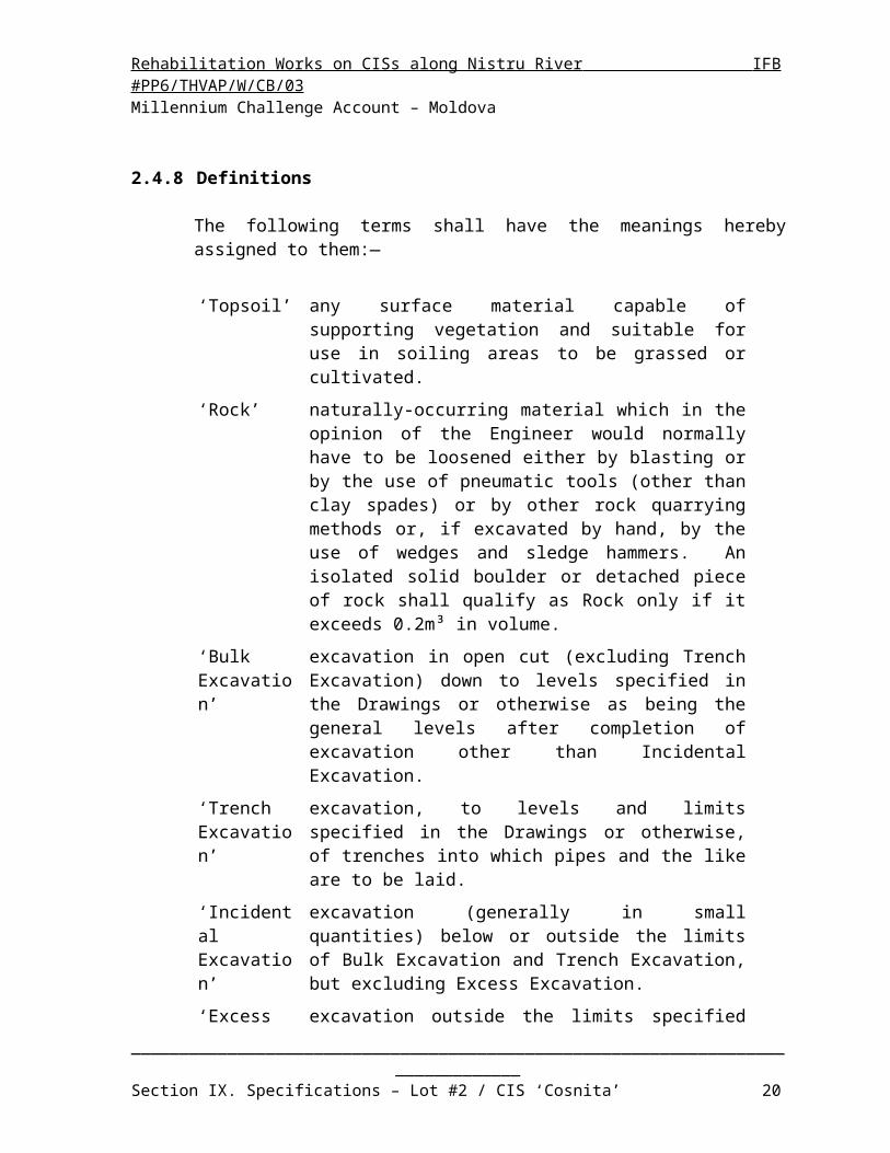
2.4.8 Definitions
The following terms shall have the meanings hereby assigned to them:—
‘Topsoil’ any surface material capable of supporting vegetation and suitable for use in soiling areas to be grassed or cultivated.
‘Rock’ naturally-occurring material which in the opinion of the Engineer would normally have to be loosened either by blasting or by the use of pneumatic tools (other than clay spades) or by other rock quarrying methods or, if excavated by hand, by the use of wedges and sledge hammers. An isolated solid boulder or detached piece of rock shall qualify as Rock only if it exceeds 0.2m³ in volume.
‘Bulk Excavation’
excavation in open cut (excluding Trench Excavation) down to levels specified in the Drawings or otherwise as being the general levels after completion of excavation other than Incidental Excavation.
‘Trench Excavation’
excavation, to levels and limits specified in the Drawings or otherwise, of trenches into which pipes and the like are to be laid.
‘Incidental Excavation’
excavation (generally in small quantities) below or outside the limits of Bulk Excavation and Trench Excavation, but excluding Excess Excavation.
‘Excess Excavation’
excavation outside the limits specified for Bulk, Trench or Incidental Excavation.
“HDPE” High Density Polyethylene
_________________________________________________________________________________Section IX. Specifications – Lot #2 / CIS ‘Cosnita’ 14

Rehabilitation Works on CISs along Nistru River IFB #PP6/THVAP/W/CB/03 Millennium Challenge Account – Moldova
2.4.9 Submission by the Contractor
Submissions which the Contractor is required to make in relation to earthworks include, where relevant, the following:
Drawings and survey notes:
— Contractor’s record drawings of the ground level survey prior to the start of any earthwork;
— information obtained from trial holes ordered by the Engineer;
— Contractor's record drawings of any other level surveys taken for the purposes of measurement of quantities of excavation or filling, such as Rock level surveys;
(Survey record drawings as specified above shall be submitted within 7 days of the completion of the survey work recorded on them.)
— survey notes on depths of Trench Excavation;
— proposals to excavate with sloping faces without support.
— general arrangements;
— general assembly, detailed shop and erection drawings;
— detailed manufacturing drawings.Data:
— calculations for connection details, where requested by the Engineer;
— welding procedure sheets.
Certificates:
— mill tests, factory tests;
— laboratory tests;
— field tests;
— conformity certificates.
Details of proposed methods:
— proposed methods of excavation, transport of materials, filling and compaction;
— proposed method of asbestos-cement handling and disposal;
_________________________________________________________________________________Section IX. Specifications – Lot #2 / CIS ‘Cosnita’ 15

Rehabilitation Works on CISs along Nistru River IFB #PP6/THVAP/W/CB/03 Millennium Challenge Account – Moldova
— proposed source of free-draining fill and methods of selective excavation or processing;
— program for quality control of earthworks and proposals for the use of off-Site laboratories.
Samples:
— materials proposed for filling and for geotextiles, where specified or where specifically required by the Engineer;
— materials proposed for filling joints between concrete slabs, pipes and concrete walls, any other joints requested by the Engineer.
_________________________________________________________________________________Section IX. Specifications – Lot #2 / CIS ‘Cosnita’ 16

Rehabilitation Works on CISs along Nistru River IFB #PP6/THVAP/W/CB/03 Millennium Challenge Account – Moldova
3 PIPELINE AND PIPEWORK
3.1 PIPE’S SUMMARY
The pipelines are briefly described and quantified in Table 3.1 below:
_________________________________________________________________________________Section IX. Specifications – Lot #2 / CIS ‘Cosnita’ 17

Rehabilitation Works on CISs along Nistru River IFB #PP6/THVAP/W/CB/03 Millennium Challenge Account – Moldova
Table 3.1 Breakdown of pipelines length for each material, diameter and type
_________________________________________________________________________________________________________________________________________________________________________________________________Section IX. Specifications – Lot #2 / CIS ‘Cosnita’ 18
PIPE Pipe Length 160 180 200 225 250 280 315 355 400 400 500 600 700 800
# [m] [m] [m] [m] [m] [m] [m] [m] [m] [m] [m] [m] [m] [m] [m]
SP1-MKP 351 0 0 0 0 0 0 0 0 0 0 0 0 0 351SP2-1KP 404 0 0 0 0 0 0 0 0 0 399 5 0 0 0SP2-2KP 711 0 0 0 307 0 0 405 0 0 0 0 0 0 0
Sub-tot. [m] 1467 0 0 0 307 0 0 405 0 0 399 5 0 0 351
SP1-1KP 3667 0 0 0 0 474 0 0 0 626 0 622 0 0 1945SP1-2KP 2925 0 0 0 0 0 0 0 943 0 0 1888 0 0 94
SP2-1KP1 1608 0 0 0 0 0 708 428 0 0 472 0 0 0 0SP2-1KP2 955 0 0 0 0 0 307 0 648 0 0 0 0 0 0SP2-2KP1 310 0 0 0 310 0 0 0 0 0 0 0 0 0 0Sub-tot. [m] 9465 0 0 0 310 474 1015 428 1591 626 472 2511 0 0 2038
SP1-1KP1 467 467 0 0 0 0 0 0 0 0 0 0 0 0 0SP1-1KP2 1223 603 0 0 620 0 0 0 0 0 0 0 0 0 0SP1-1KP3 450 450 0 0 0 0 0 0 0 0 0 0 0 0 0SP1-1KP4 1217 592 0 0 625 0 0 0 0 0 0 0 0 0 0SP1-1KP5 595 595 0 0 0 0 0 0 0 0 0 0 0 0 0SP1-1KP6 484 484 0 0 0 0 0 0 0 0 0 0 0 0 0SP1-1KP7 1360 0 737 0 0 623 0 0 0 0 0 0 0 0 0SP1-1KP8 504 0 504 0 0 0 0 0 0 0 0 0 0 0 0SP1-1KP9 276 0 276 0 0 0 0 0 0 0 0 0 0 0 0
SP1-1KP10 1018 0 0 396 0 621 0 0 0 0 0 0 0 0 0SP1-1KP11 1224 0 0 599 0 625 0 0 0 0 0 0 0 0 0SP1-1KP12 1223 0 0 563 0 660 0 0 0 0 0 0 0 0 0SP1-1KP13 1192 0 0 586 0 606 0 0 0 0 0 0 0 0 0SP1-1KP14 943 0 0 322 0 621 0 0 0 0 0 0 0 0 0SP1-1KP15 1179 0 0 563 0 616 0 0 0 0 0 0 0 0 0SP1-1KP16 1331 0 0 687 0 644 0 0 0 0 0 0 0 0 0SP1-2KP1 1141 578 0 0 563 0 0 0 0 0 0 0 0 0 0SP1-2KP2 570 570 0 0 0 0 0 0 0 0 0 0 0 0 0SP1-2KP3 512 512 0 0 0 0 0 0 0 0 0 0 0 0 0SP1-2KP4 550 550 0 0 0 0 0 0 0 0 0 0 0 0 0SP1-2KP5 568 568 0 0 0 0 0 0 0 0 0 0 0 0 0SP1-2KP6 741 0 0 741 0 0 0 0 0 0 0 0 0 0 0SP1-2KP7 526 526 0 0 0 0 0 0 0 0 0 0 0 0 0SP1-2KP8 822 0 0 822 0 0 0 0 0 0 0 0 0 0 0SP1-2KP9 422 422 0 0 0 0 0 0 0 0 0 0 0 0 0
SP1-2KP10 828 0 0 828 0 0 0 0 0 0 0 0 0 0 0SP1-2KP11 321 321 0 0 0 0 0 0 0 0 0 0 0 0 0SP1-2KP12 719 0 0 719 0 0 0 0 0 0 0 0 0 0 0SP1-2KP13 155 155 0 0 0 0 0 0 0 0 0 0 0 0 0SP1-2KP14 631 0 0 631 0 0 0 0 0 0 0 0 0 0 0SP1-2KP15 533 0 0 533 0 0 0 0 0 0 0 0 0 0 0SP1-2KP16 668 0 0 668 0 0 0 0 0 0 0 0 0 0 0SP2-1KP1.1 1044 0 0 0 0 1044 0 0 0 0 0 0 0 0 0SP2-1KP1.2 1375 0 0 0 0 1050 324 0 0 0 0 0 0 0 0SP2-1KP1.3 285 285 0 0 0 0 0 0 0 0 0 0 0 0 0SP2-1KP1.4 96 96 0 0 0 0 0 0 0 0 0 0 0 0 0SP2-1KP2.1 477 477 0 0 0 0 0 0 0 0 0 0 0 0 0SP2-1KP2.2 377 0 0 0 377 0 0 0 0 0 0 0 0 0 0SP2-1KP2.3 789 0 0 789 0 0 0 0 0 0 0 0 0 0 0SP2-1KP2.4 495 0 0 495 0 0 0 0 0 0 0 0 0 0 0SP2-1KP2.5 840 0 0 840 0 0 0 0 0 0 0 0 0 0 0SP2-1KP2.6 83 0 0 83 0 0 0 0 0 0 0 0 0 0 0SP2-2KP1.1 603 0 0 603 0 0 0 0 0 0 0 0 0 0 0SP2-2KP1.2 107 0 0 107 0 0 0 0 0 0 0 0 0 0 0SP2-2KP1.3 629 0 0 629 0 0 0 0 0 0 0 0 0 0 0SP2-2KP1.4 214 0 0 214 0 0 0 0 0 0 0 0 0 0 0SP2-2KP1.5 912 0 0 912 0 0 0 0 0 0 0 0 0 0 0Sub-tot. [m] 32719 8251 1517 13332 2185 7110 324 0 0 0 0 0 0 0 0
Tot [m ] 43650 8251 1517 13332 2801 7584 1340 833 1591 626 871 2516 0 0 2389
Tertiary pipes
Group 3 -COSNITA CIS: QUANTITY
ASSESSMENT
SP-1, SP-2
HDPE100, NP8 Steel
Main pipes
Secondary pipes
PIPE Pipe Length 160 180 200 225 250 280 315 355 400 400 500 600 700 800
# [m] [m] [m] [m] [m] [m] [m] [m] [m] [m] [m] [m] [m] [m] [m]
SP3-MK 1365 0 0 0 0 0 0 0 0 0 0 0 0 0 1365SP4-MKP1 150 0 0 0 0 0 0 0 0 150 0 0 0 0 0SP4-MKP2 98 0 0 0 0 0 0 0 0 0 0 98 0 0 0Sub-tot. [m] 1613 0 0 0 0 0 0 0 0 150 0 98 0 0 1365
Secondary pipesSP3-1KP 4817 0 0 0 370 0 626 0 645 308 0 624 844 904 495SP3-2KP 227 0 0 0 227 0 0 0 0 0 0 0 0 0 0SP4-T1 1051 0 0 199 465 0 0 386 0 0 0 0 0 0 0SP4-T2 2660 0 0 0 293 0 0 347 0 146 0 1873 0 0 0SP4-T4 319 0 0 0 319 0 0 0 0 0 0 0 0 0 0
Sub-tot. [m] 9073 0 0 199 1674 0 626 734 645 454 0 2497 844 904 495 Tertiary pipesSP3-1.1KP 3080 0 0 0 2108 972 0 0 0 0 0 0 0 0 0SP3-1KP1 618 618 0 0 0 0 0 0 0 0 0 0 0 0 0SP3-1KP2 591 591 0 0 0 0 0 0 0 0 0 0 0 0 0SP3-1KP3 708 708 0 0 0 0 0 0 0 0 0 0 0 0 0SP3-1KP4 590 590 0 0 0 0 0 0 0 0 0 0 0 0 0SP3-1KP5 712 712 0 0 0 0 0 0 0 0 0 0 0 0 0SP3-1KP6 643 643 0 0 0 0 0 0 0 0 0 0 0 0 0SP3-1KP7 515 515 0 0 0 0 0 0 0 0 0 0 0 0 0SP3-1KP8 641 641 0 0 0 0 0 0 0 0 0 0 0 0 0SP3-1KP9 642 642 0 0 0 0 0 0 0 0 0 0 0 0 0
SP3-1KP10 642 642 0 0 0 0 0 0 0 0 0 0 0 0 0SP3-1KP11 615 615 0 0 0 0 0 0 0 0 0 0 0 0 0SP3-1KP12 644 644 0 0 0 0 0 0 0 0 0 0 0 0 0SP3-1KP13 489 489 0 0 0 0 0 0 0 0 0 0 0 0 0SP3-1KP14 634 634 0 0 0 0 0 0 0 0 0 0 0 0 0SP3-1KP15 477 477 0 0 0 0 0 0 0 0 0 0 0 0 0SP3-1KP16 425 425 0 0 0 0 0 0 0 0 0 0 0 0 0SP3-1KP17 365 365 0 0 0 0 0 0 0 0 0 0 0 0 0SP3-1KP18 641 641 0 0 0 0 0 0 0 0 0 0 0 0 0SP3-1KP19 292 292 0 0 0 0 0 0 0 0 0 0 0 0 0SP3-1KP20 637 637 0 0 0 0 0 0 0 0 0 0 0 0 0SP3-1KP21 229 229 0 0 0 0 0 0 0 0 0 0 0 0 0SP3-1KP22 224 0 0 0 224 0 0 0 0 0 0 0 0 0 0SP3-1KP23 616 616 0 0 0 0 0 0 0 0 0 0 0 0 0SP3-2KP1 596 596 0 0 0 0 0 0 0 0 0 0 0 0 0SP3-2KP2 986 587 0 0 398 0 0 0 0 0 0 0 0 0 0SP4-T1-1 1052 0 0 1052 0 0 0 0 0 0 0 0 0 0 0SP4-T1-2 915 0 0 915 0 0 0 0 0 0 0 0 0 0 0SP4-T1-3 712 0 0 712 0 0 0 0 0 0 0 0 0 0 0SP4-T1-4 662 0 0 662 0 0 0 0 0 0 0 0 0 0 0SP4-T2-1 1910 0 0 0 0 0 1910 0 0 0 0 0 0 0 0SP4-T2-2 865 0 865 0 0 0 0 0 0 0 0 0 0 0 0SP4-T2-3 1472 0 0 1472 0 0 0 0 0 0 0 0 0 0 0SP4-T2-4 1330 0 773 0 557 0 0 0 0 0 0 0 0 0 0SP4-T2-5 1721 0 0 823 899 0 0 0 0 0 0 0 0 0 0SP4-T3 1539 0 0 0 1539 0 0 0 0 0 0 0 0 0 0
SP4-T3-1 968 968 0 0 0 0 0 0 0 0 0 0 0 0 0SP4-T4-1 206 206 0 0 0 0 0 0 0 0 0 0 0 0 0SP4-T4-2 753 0 0 753 0 0 0 0 0 0 0 0 0 0 0
Sub-tot. [m] 31357 14725 1639 6389 5724 972 1910 0 0 0 0 0 0 0 0Tot [m ] 42043 14725 1639 6588 7398 972 2536 734 645 605 0 2594 844 904 1860
Group 3 -COSNITA CIS: QUANTITY
ASSESSMENT
SP-3, SP-4
HDPE100, NP8 Steel
Main pipes

Rehabilitation Works on CISs along Nistru River IFB #PP6/THVAP/W/CB/03 Millennium Challenge Account – Moldova
3.2 STEEL PIPES
3.2.1 General
The pipelines must be manufactured according to General Technical Specification requirements, as per clause 5.2.2. The pipelines are briefly described and quantified in Table 3-1.
Steel pipes and fittings shall be manufactured by a spiral or longitudinal weld process and shall conform to the requirements of EN 10224. Steel quality shall conform with EN 10025 grade S275JR. Outside diameters and wall thicknesses shall comply with EN 10024, where otherwise specified, with wall thicknesses as shown on the drawings.
Pipes shall either be coated externally when laid underground as per clause 3.2.2, or painted externally with epoxy lining of 400 micron in thickness when laid above ground, in ducts or inside buildings. In both cases they shall be internally lined at the manufacturer's works with either an approved epoxy-based or similar lining. The finished internal lining shall be continuous across all welded joints.
Pipes shall be supplied with plain ends either to fit flexible couplings or suitable for butt welding.
All pipes and specials to be joined by welding shall have the external protection stopped back at the ends at a distance sufficient to permit welding of the joints without damage to the protection, as further detailed hereafter.
For other than welded joints, the external protection shall, if necessary, be stopped back at a distance sufficient to permit assembly of the joint.
The internal protection shall extend to the end of pipes to be jointed by flexible couplings, and shall be stopped back as specified hereafter for pipes to be butt welded.
For pipes jointed by welding or by flanged joints, external protection shall be completed using the identical coating and lining material and material profile used on the main pipe barrel. Alternatively, the joint may be wrapped to a similar standard and thickness of protection using appropriate tape and paste or other protective material, all of which subject to the approval of the Engineer.
Straight pipes shall be supplied in nominal lengths of 12 m or as otherwise agreed with the Engineer.
Branches shall be formed by welding and shall be welded before the pipe is erected.
_________________________________________________________________________________Section IX. Specifications – Lot #2 / CIS ‘Cosnita’ 19
Rehabilitation Works on CISs along Nistru River IFB #PP6/THVAP/W/CB/03 Millennium Challenge Account – Moldova
Pipe flanges shall be either “steel welding neck flanges” or “steel plate flanges for welding”, both conforming to up to 40 bar, or to other equivalent and approved standard, and welded on in accordance with UNI-EN 2277-2278 or to other equivalent and approved standard.
The pipes shall be supplied with plain ends, and should be coupled by butt welding according UNI-EN 10520, if not otherwise specified elsewhere.
3.2.2 Coating & Lining of underground pipe and Fittings
The steel pipes to be laid underground shall be coated as following specified:
Passive external protection of pipes and fittings shall be provided by the application of polyethylene and polyurethane-modified coating, respectively;
Internal protection of pipes and fittings shall be provided by the application of a liquid epoxy lining (400 microns dry thickness).
Save as otherwise prescribed by this Specification, the following Standards shall apply: DIN 30670/91 (Polyethylene coating for steel pipes and fittings); UNI 9099/89 (Steel pipes and fittings for buried or submerged pipelines -
External polyethylene coating applied by extrusion); DIN 30671/92 (Thermoset plastic coatings for buried steel pipes); NF A 49-706/86 (Revêtement externe en poudre époxydique sur tubes); NF A 49-709/92 (Pitch based polyurethane and epoxy painting for internal
coating of steel water pipelines); AWWA C210/92 (Liquid epoxy coating system for the interior and exterior of
steel water pipelines); ISO 527-3/95 (Plastics - Determination of tensile properties - Test conditions for
films and sheets); ISO 868/85 (Plastics and ebonite - Determination of indentation hardness by
means of a durometer); ISO 2808/91 (Paints and varnishes - Determination of film thickness); ISO 4287-1/84 (Surface roughness - Terminology - Surface and its parameters); ISO 8501-1/94 (Preparation of steel substrates before application of paints and
related products - Visual assessment of surface cleanliness).
This Specification covers the minimum technical requirements for the preparation and application of the coating and lining of the steel pipes and fittings, and the Contractor shall submit fully detailed proposals of the coating and lining systems for the Engineer's approval.
The results of previous tests performed at the factory may be considered by the Engineer when reviewing the proposed coating and lining procedure; such results shall be made available to the Engineer well in advance of the start of coating and lining operations.
_________________________________________________________________________________Section IX. Specifications – Lot #2 / CIS ‘Cosnita’ 20

Rehabilitation Works on CISs along Nistru River IFB #PP6/THVAP/W/CB/03 Millennium Challenge Account – Moldova
The Engineer may require delivery, at no cost to the Employer, of pipe sections coated and lined previously in accordance with the proposed procedure, for his inspection and approval. These pipe sections shall be chosen at random by the Engineer and shall be submitted to all the tests listed in this Specification.
All work at the coating and lining factory shall be subject to inspection by the Engineer who shall be given 30 days’ notice before the commencement of said work.
The Contractor at no additional cost shall make any defective work good to the Employer.
The Engineer shall have the right to reject any and all tools, instruments, materials, staging, equipment, or work which do not conform with or impair the Specification.
Any rejected tools, instruments, materials or equipment shall be replaced or made good at no additional cost to the Employer.
3.2.2.1 Preparation of Metal Surfaces
At the time of application of the coating and of the lining, the surface to be coated or lined shall be dry and free from soiling (such as previous coatings, paint and loose particles, grease, oil, salts, etc.) and surface defects (slivers, laminations, etc.) harmful to surface preparation or to adhesion.Abrasive blast cleaning shall be carried out to ensure suitable preparation of the external and internal surfaces of the pipe to be coated and lined. This treatment shall be carried out by the impact of an abrasive so as to obtain an overall surface condition corresponding at least to Sa 2½ as defined in DIN 55 928 Part 4. (Equivalent to SIS 055900 - Swedish Standard).
3.2.2.2 External Polyethylene Coating for Pipes (PE)
The principle of this coating is that it shall consist of three layers: epoxy primer, adhesiveand polyethylene according DIN 30 670/91.
The coating shall be applied at the factory in accordance with the established procedure and in full compliance with the specifications of the manufacturer of the epoxy primer, adhesive and polyethylene.
(a) Preheating
Coating application may require preheating of the pipeas recommended in the specifications of the manufacturer of the epoxy primer, adhesive and polyethylene. Application temperature shall be less than 250°C.
If the surface is affected by colour change or contamination, the pipe shall be allowed to cool inair to ambient temperature and re-cleaned.
Pipes heated above 250°C shall not be coated.
_________________________________________________________________________________Section IX. Specifications – Lot #2 / CIS ‘Cosnita’ 21

Rehabilitation Works on CISs along Nistru River IFB #PP6/THVAP/W/CB/03 Millennium Challenge Account – Moldova
(b) Layer 1
This layer shall be formed by a film of liquidepoxy resin or powder epoxy resin. If fusion-bonded powder epoxy is applied, particular care shall be taken to ensure that the temperatures required during the application process do not damage coatings and/or linings previously applied. The minimum dry thickness of the liquid epoxy and powder epoxy resin shall be respectively 30m and 60m.
(c) Layer 2
This layer shall be formed by a polymer adhesive intended to provide adhesion between layers 1 and 3 and be compatible with those layers. The minimum thickness shall be between 150m and 200m, depending on the type of adhesive and the application. The thickness shall be uniform and shall be such as to satisfy the tests specified in DIN 30 670/91.
(d) Layer 3
This layer shall be formed by the polyethylene coating. The thickness shall be uniform and the minimum total thickness shall satisfy the requirements of DIN 30 670/91.
Pigments and additives may be added to the basic polyethylene, provided that all the required properties of the coating are obtained. Pigment shall be uniformly dispersed.
When the coater adds pigments and additives to the basic polyethylene, the required properties must be certified by a documented quality programme. The following tests shall be undertaken, as a minimum:
- quantitative analysis of the raw-material components before coating- determination of dispersion of pigments and additives.
3.2.2.3 Thickness of external Polyethylene Coating for Pipes (PE)
Coating thickness shall be measured in accordance with the method defined in DIN 30670/91.
The minimum thickness of the coating system at any point shall correspond to the values given below: DN 500 mm pipe 2.5 mm DN 600 to 750 mm pipe 2.8 mm DN > 750 mm pipe 3.0 mm
The thickness may be reduced by 10%, for welded pipes, at the weld reinforcement.For pipes laid in steep conditions, the minimum thickness of the coating shall be 3.5 mm, as instructed by the Engineer.
3.2.2.4 Composition and Application of Internal Epoxy Lining
_________________________________________________________________________________Section IX. Specifications – Lot #2 / CIS ‘Cosnita’ 22

Rehabilitation Works on CISs along Nistru River IFB #PP6/THVAP/W/CB/03 Millennium Challenge Account – Moldova
Lining material shall be liquid epoxy, solvent free, of the two component type. It shall also satisfy all current applicable health and safety requirements with regard to suitability for use in potable water services.
The principle of this lining is that it shall consist of one layer of epoxy resin.
The lining shall be applied in the factory in accordance with the established procedure and specifications of the manufacturer.
The content of technical data sheets and certificates of materials for liquid epoxy lining shall be submitted to Engineer for approval.
(a) Mixing
Resin and hardener shall be supplied in separate containers.
Each pack shall be stirred or agitated to a homogeneous state before any material is withdrawn from its container.
Resin and hardener shall be thoroughly mixed in the proportions specified by the product manufacturer.
The two packs shall be supplied in different colours, if possible, and evidence of complete mixing shall be when a uniform colour is achieved without any "streaking".
The quantity of material made up at one time shall not exceed that which can be used within the pot life stated by the product manufacturer or that necessary to ensure complete coverage of the area to be coated.
(b) General application procedure
Immediately after the abrasive blast cleaning, a layer of liquid thermosetting lining shall be applied by brush, by the airless spray technique or by other methods in accordance with the product manufacturer’s instructions. Particular care shall be taken to avoid damage to the liquid epoxy lining if applied prior to other coatings which might require high processing temperatures.
Lining shall be carried out using the equipment recommended by the manufacturer.
The lining shall be uniform.
If a second layer is required to reach the specified thickness, this shall be applied in accordance with the over coating time prescribed by the product manufacturer.
Wet thickness shall be measured according to ISO 2808/91.
Particular attention shall be paid to the recommended dry film thickness, which shall be measured in accordance with the method defined in UNI 9099/89.
_________________________________________________________________________________Section IX. Specifications – Lot #2 / CIS ‘Cosnita’ 23

Rehabilitation Works on CISs along Nistru River IFB #PP6/THVAP/W/CB/03 Millennium Challenge Account – Moldova
If pre-heating of one or more of the coating material packs prior to mixing and application, or a post-heating of the coating after application, is required, this shall be done according to the product manufacturer's recommended procedure.
No thinners shall be used unless recommended by the product manufacturer and tools and equipment shall be cleaned using only such solvents as are recommended bythe product manufacturer.
Particular care shall be taken in the handling of the components before the coating has reached the minimum value of the hardness recommended by the product manufacturer.
3.2.2.5 Dry thickness Internal Epoxy Lining
Lining thickness shall be measured in accordance with the method defined in UNI 9099/89. The dry thickness of the lining system at any point shall correspond to 400m 25m.
3.2.2.6 Inspection
(a) Documentation
Inspection operations shall be carried out by the coater and liner as agreed at the time of procurement and submitted to the prior written approval of the Engineer. A representative appointed by the Engineer may witness these operations.
The results of these inspection operations shall be recorded by the coater and liner and shall be made immediately available to the Engineer.
(b) Sampling
The Engineer’s representative shall select the pipes on which the specified tests shall be carried out.
The test pieces for destructive testing shall be taken, if possible, from the ends of the pipes. Samples and the test pipes shall be marked in order to be fully and easily identifiable.
(c) Unit of product and material traceability
A unit shall be taken as meaning a set of pipes coated and lined under the following conditions:- the same type of manufacturing technique and same production line- the same outside diameter and same thickness of pipe- the same production run- the same production batch of material.
(d) Nature and frequency of testing and control
_________________________________________________________________________________Section IX. Specifications – Lot #2 / CIS ‘Cosnita’ 24

Rehabilitation Works on CISs along Nistru River IFB #PP6/THVAP/W/CB/03 Millennium Challenge Account – Moldova
The nature and frequency of the testing and control on factory shall be as stated in DIN 30670/01. The procedures and frequency for the testing of the field lining of the internal and external surface shall be submitted to the prior approval of the Engineer.
(e) Marking
Each pipe and fitting shall be uniquely marked ; the marking shall include the following: identification; code or name of the producer of the steel ; applicator code, if it differs from the preceding code; reference to the steel standard; reference to this Specification followed by the thickness of the pipe wall,
of the coating and of the lining, in this order.
Marking shall be carried out using a suitable method such as stencil painting or printing, making legible and indelible identification possible, using durable materials compatible with the subsequent use of the pipes and components.
3.2.2.7 Field Completion of the Internal Epoxy Lining at Welded Pipe Joints
(a) General
This part of the Specification shall govern the surface preparation, material application and inspection requirements for the field completion of the internal epoxy lining, at welded pipe-joints.
The details given herein shall be construed as minimum guidelines only and the Contractor shall submit for the Engineer's approval a fully detailed system for field completion of linings.
Lining applied in the field shall be carried out in compliance with the liquid epoxy manufacturer’s recommendations.
All work shall be subject to inspection by the Engineer who shall be given 7 (seven) days notice prior to its commencement.
The Engineer shall have the right to condemn any and all tools, instruments, materials, equipment or work which does not conform to the Specification.
Any condemned lining application or any defective work shall be replaced or rectified by the Contractor at no additional cost to the Employer.
_________________________________________________________________________________Section IX. Specifications – Lot #2 / CIS ‘Cosnita’ 25

Rehabilitation Works on CISs along Nistru River IFB #PP6/THVAP/W/CB/03 Millennium Challenge Account – Moldova
In cases where the Contractor wishes to deviate from this Specification, all relevant details concerning materials, components, equipment, application and testing procedures, and remedies, shall be submitted for the Engineer's approval. Proposals for changes shall be made within such time that should said proposals not be approved by the Engineer, the work, when executed in full accordance with this Specification, shall not affect or delay completion of the Works.
(b) Raw material
The material utilized shall be liquid epoxy applied cold by spraying in such manner as to produce an effective bond with the underlying steel.
It shall also satisfy all current applicable governmental health and safety requirements with regard to suitability for use in potable water services and shall be fully compatible with the epoxy previously applied in the factory to line the internal surface of the pipes and fittings.
(c) Joint lining
(i) Preparation of the internal pipe joint surface before joint weldingAll corrosion products and any pre-existing lining shall be removed from the internal pipe surface for a length of 150 to 200 mm from the pipe edges until the metal surface is clearly visible and dry.The metal surface shall then be thoroughly cleaned by scraping and wire-brushing or sand-blasting.The surface shall have a pronounced metallic sheen and correspond to C St 3 of ISO 8501-1/94.
(ii) Preparation of the internal pipe joint surface after joint weldingAll sharp edges on welds shall be removed.The surface to be lined shall be roughened with a wire brush. The adjacent lined surface shall also be lightly roughened.All traces of dust and of loose or foreign particles shall be removed using a suitable aspirator.
(iii) Lining of the internal pipe joint surface after weldingThe lining shall be applied by a suitable system (e.g. cross-spraying) in such a way that the resulting film shall not be so heavy that it will run on vertical surfaces.An appropriate number of layers shall be applied to obtain the dry film lining thickness specified hereafter. Each layer shall provide an effective bond between the preceding and the subsequent layer.The lining shall overlap the main body of the pre-existing lining on each side of the weld, for a length of at least 50 mm, to form a continuous lined surface free from defects.
(iv) Lining thicknessThe dry film thickness shall be 450 m ± 25m.
_________________________________________________________________________________Section IX. Specifications – Lot #2 / CIS ‘Cosnita’ 26

Rehabilitation Works on CISs along Nistru River IFB #PP6/THVAP/W/CB/03 Millennium Challenge Account – Moldova
The dry film shall be uniform and shall not contain bare spots or holidays.
(d) Testing and inspection
The procedures for the testing of the field lining of the internal surface of welded pipe-joints shall be submitted to the prior approval of the Engineer.
(i) Test samplesThe Engineer may require delivery (at no cost to the Employer) of samples of internally lined welded joints, having a length of approximately 1m, cut from welded pipe sections, for his inspection and approval.The Engineer's representative may require to be present at the welding, internal lining of pipe-joints and cutting of the samples.During construction of the pipeline the Engineer may, at no cost to the Employer, require cutting of a joint sample every 2000 welded joints and performance thereon of the following internal joint surface lining tests, to check:a) length of overlap between the joint lining and the pre-existing liningb) lining uniformityc) lining thicknessd) bond between liningse) adherence of the lining to the underlying metalf) surface preparation.If the results of one of these tests fails to meet any of the specified requirements, two additional joint samples shall be cut every 2000 completed joints after the preceding satisfactory test.
If the results of one of the tests on one of these joints do not meet the specified requirements, the Contractor shall cut an additional two joints and so forth.
(ii) Lining thicknessLining thickness of field lined joints shall be assessed on the basis of the quantity of material sprayed per square meter of lined surface.Lining thickness of joint samples shall be evaluated as the mean of the thicknesses measured in 10 randomly selected points.In all cases, each thickness value shall not be less than 425 m.Dry film thickness shall be measured by a non-destructive test instrument (e.g. Elcometer, Mikrotest).
(iii) AdhesionAdhesion tests shall be performed in accordance with the requirements of AWWA C210/32 (V-cut adhesion).
(iv) Holiday detection
_________________________________________________________________________________Section IX. Specifications – Lot #2 / CIS ‘Cosnita’ 27

Rehabilitation Works on CISs along Nistru River IFB #PP6/THVAP/W/CB/03 Millennium Challenge Account – Moldova
The procedures for the performance of the holiday detection test shall be proposed by the Contractor and shall be subject to the approval of the Engineer.The test shall be considered satisfactory if the lined joint surface does not give rise to any defects.If the test has failed, the Contractor shall apply another layer to the lining and a further test shall be carried out until the test is satisfactory.
3.2.2.8 Field Completion of the External Coating at Welded Pipe Joints
The Contractor shall provide full details of the materials and methodology to be utilised for the completion of the external coating at welded pipe joints, so as to ensure compatibility with, and protection characteristics not inferior to, those required for the external coating of the tubes, all of which shall be subject to the prior written approval of the Engineer who may also require prior testing on welded joint specimens.
3.2.3 Handling Transportation and Storage of Coated and Lined Steel Pipes and Fittings
Handling : Pipes and fittings shall be handled so as not to cause damage to chamfers or coating or lining. The direct use of steel or hemp slings or of any equipment of a shape or nature likely to damage to the coating or lining is prohibited.
Coated and lined pipes shall be handled using aluminium, brass or padded end hooks, wide non-metallic slings or padded calipers, taking such care as required to ensure their integrity at all times.
Separation of pipes during transport: Suitable precautions, such as padding placed horizontally and vertically, shall be taken to ensure that pipe coatings are not damaged during transport.
Trucking: Suitable hauling equipment shall be provided to minimize coating damage. All chains and pipe supports shall have sufficient padding between them and the coated pipe to prevent damage. Binders, straps and belts shall be padded where required. Truck trailers shall be free of obstructions, which may cause damage to the coated pipe.
Rail transport: The bottom of rail cars shall be cleaned so that they are free of any obstructions, which may cause damage to the coated pipe. Rail transportation of coated pipes shall be in conformity with API Recommended Practice 5L1 (RP5L1), Third Edition, April 1972.
Marine transportation: Marine transportation of coated pipes shallbe in conformity with API Recommended Practice RP 5L5, First Edition, March 1975.
_________________________________________________________________________________Section IX. Specifications – Lot #2 / CIS ‘Cosnita’ 28

Rehabilitation Works on CISs along Nistru River IFB #PP6/THVAP/W/CB/03 Millennium Challenge Account – Moldova
Storage: Storage areas shall be free from rocks, stones, sticks and other protrusions, and shall be welldrained.
The contact area of skids shall be padded, e.g. with rubber, canvas, belting, pressed fiberboard, etc. A padded wedgeshall also be used to prevent side-roll movement of bottom row pipes.
A suitable covering shall be provided to coated pipes for their protection from ultraviolet deterioration when pipes are expected to be stored or exposed in the open for a period of 6 months or more.
At all times storage conditions shall be such that each pipe and fitting is not in direct contact with the ground and the coatings and linings are not damaged in any manner.
3.3 HDPE PIPE
The pipelines must be manufactured in according General Technical Specification requirement, as per clause 5.2.2.3.
The pipes shall be supplied with plain ends, and should be coupled by butt-welding according UNI 10520, if not otherwise specified elsewhere.
3.4 CROSSING UNDER ROADS AND RAILWAY TRACKS
3.4.1 General
The following specification covers the requirements for the detailed design, construction, installation and testing of Pipelines at road and railway track crossings by Non Disruptive Road Crossing (NDRC) method.
Where irrigation pipes cross roads and rail crossing, such crossings shall be carried out by means of horizontal under road boring and sleeving methods. If the road or rail reserve has to be dug up to install a pipe then at least on spare pipe sleeve shall be installed, if there are no existing spare sleeves.
The minimum depth of cover over the top of the sleeves when crossing under a road or a rail line is 1200mm.
The Contractor shall perform the works by thrust boring or microtunnelling or similar method previously approved by Engineer, by the concerned road and railway Authorities and in accordance with the main relevant Moldovan norms and laws in force.
Before starting the work the Contractor shall obtain all necessary permits from the relevant authorities and take into account required advance warning periods.
_________________________________________________________________________________Section IX. Specifications – Lot #2 / CIS ‘Cosnita’ 29

Rehabilitation Works on CISs along Nistru River IFB #PP6/THVAP/W/CB/03 Millennium Challenge Account – Moldova
Methods and scheduling of crossing shall be such as to minimize delay or obstruction to traffic. Where instructed, crossings shall be constructed a half width at a time to maintain traffic movement.
The Contractor shall submit for Engineer approval a detailed method statement for the required work. Where a pipeline is to be constructed by NDRC, the Contractor shall confine his surface operations to working shafts and the area immediately adjacent to such shafts.
Such working area shall be kept to the minimum practicable for the proper construction of the works. The Contractor shall propose the location of all working shafts, having due regard to existing services, minimising disruption to traffic and pedestrian movements and achieving the required system layouts, as shown on the drawings.
The Engineer prior to the commencement of construction shall approve the locations of all working shafts. The Contractor shall obtain approval of his method statement from the concerned road and railway.
3.4.2 Detailed Design
The Contractor shall be responsible for the detailed design of the pipes including all joints, for the design of the thrust and reception pits including support and thrust wall and for the design of the jacking system in general. His design shall have the Engineer's and concerned authorities’ approval.
The following shall be submitted by the Contractor and approved by the Engineer prior to commencement of any NDRC site activity.
a. Programme of works with resource and equipment allocations.
b. Soils Investigation Report.
c. Design Calculations: i) Pipes including jacking and friction forces in the axial direction and earth, traffic and surcharge loadings in the vertical direction and the pipes resistance to these loads. Also, allowable deflections at joints to limit damage to the joint from eccentric loading under thrust and sealing limits. ii) Thrust and reception pits to resist external soil and water pressures and stresses resulting from jacking machine. Drawings showing on plan and sections, the method of supporting excavations and equipment layout shall be included. iii) All calculations shall be certified/signed by a qualified engineer.
d. Materials Specification.
_________________________________________________________________________________Section IX. Specifications – Lot #2 / CIS ‘Cosnita’ 30

Rehabilitation Works on CISs along Nistru River IFB #PP6/THVAP/W/CB/03 Millennium Challenge Account – Moldova
e. Method Statements which shall include: i) List of equipment and resources. ii) Detailed step by step procedure describing how the works will be carried out including clear definition of Contractor responsibilities and authority. iii) Support of existing services and adjacent structures. iv) Safety arrangements for compliance with safety requirements. v) Arrangements for dealing with groundwater taking due regard to controlling the loss of material and preventing settlement around pits, pit/pipe interface and tunnel face. vi) Dealing with different ground conditions. vii) Locking pipe in position during insertion of next pipe. viii) Sealing thrust and reception pits during exiting and entering of pipe. ix) Control of over-break. x) Grout mix design and method of grouting. xi) Handling and fixing of the inner pipe in the case of thrust boring/microtunnelling with larger diameter casing/pipes.
3.4.3 Site Investigation
The Contractor shall be responsible for carrying out all needed integrative geotechnical site investigations, including groundwater level monitoring, which he considers necessary but as a minimum at the proposed thrust pit location, reception pit location and central median. The Contractor’s investigation programme shall be submitted to the Engineer for review. The results of such investigations shall be submitted to the Engineer and shall include recommendations for excavation support and soil stabilisation if required. The Contractor shall be responsible for obtaining existing utility information and executing trial pits to locate and confirm services at pit locations, etc., as required.
3.4.4 Records
The Contractor shall maintain and submit to the Engineer after each shift a log, which records: i) Identification number of pipes installed during shift and name of operator. ii) Strata encountered. iii) Position and orientation of the lead ten pipes. iv) Forces used on both main and inter-jack rams during driving of each pipe.
3.5 FITTINGS
3.5.1 Steel elbow
The pipelines must be constructed on site as is indicated in drawings. The material, diameter and wall thickness of the steel elbow shall be the same as the pipes to connect with and shall comply with the General Technical Specification requirement, as per clause 5.2.2.2. Connection of steel elbows to the pipe to connect with shall be butt-welding and shall comply with the General Technical Specification requirement, as per clause 5.2.2.2. Steel elbow shall not be measured as a separate item and shall be deemed fully included in the unit price of steel pipe.
3.5.2 HDPE elbows
The elbows must be manufactured according clause 5.2.2.3 of General TS.
_________________________________________________________________________________Section IX. Specifications – Lot #2 / CIS ‘Cosnita’ 31

Rehabilitation Works on CISs along Nistru River IFB #PP6/THVAP/W/CB/03 Millennium Challenge Account – Moldova
Elbows shall be supplied with plain ends suitable for welding. The elbows shall be manufactured according UNI EN 12201-3, and the welding coupling shall be according UNI 10520. The shape, dimensions and sizes of all the fittings shall be as shown on drawings.
3.5.3 HDPE reduction
The reduction must be manufactured in according clause 5.2.2.3 of General TS.
Reductions shall be supplied with plain ends suitable for welding. The reductions shall be manufactured according UNI EN 12201-3, and the welding coupling shall be according UNI 10520. The shape, dimensions and sizes of all the fittings shall be as shown on drawings.
3.5.4 Steel flanged reduction
The reductions must be manufactured in according clause 5.2.2.2 of General TS. Steel reductions shall be welded to steel flat flanges, according UNI-EN 15614-1. The shape, dimensions and sizes of all the fittings shall be as shown on drawings.
3.5.5 HDPE Tee piece
The tee piece must be manufactured in accordance with clause 5.2.2.3 of General TS.
Tees shall be supplied with plain ends suitable for welding. The HDPE Tee fittings shall be manufactured according UNI EN 12201-3, and the welding coupling shall be according UNI 10520. The shape, dimensions and sizes of all the fittings shall be as shown on drawings.
3.5.6 HDPE flange adaptor
The flange adaptor must be manufactured in according clause 5.2.2.3 of General TS.
The flange adaptors shall be supplied with plain ends suitable for welding. The adaptors shall be manufactured according UNI EN 12201-3, and the welding coupling shall be according UNI 10520. The shape, dimensions and sizes of all the fittings shall be as shown on drawings.
3.5.7 Steel flanged Tee/Cross
The steel tees must be manufactured in according clause 5.2.2.2 of General TS. Steel tees shall be welded to steel flat flanges, according UNI-EN 15614-1. The shape, dimensions and sizes of all the fittings shall be as shown on drawings.
_________________________________________________________________________________Section IX. Specifications – Lot #2 / CIS ‘Cosnita’ 32

Rehabilitation Works on CISs along Nistru River IFB #PP6/THVAP/W/CB/03 Millennium Challenge Account – Moldova
3.5.8 Steel flange
The steel flanges for stub end must be manufactured and jointed according UNI-EN 1092. Steel flanges shall be supplied with all connecting components: bolts, nuts, washers, gasket. The shape, dimensions and sizes of all the flanges shall be as shown on drawings.
3.5.9 Special flanged HDPE T-piece
The special flanged T-piece will be used to construct hydrants as is indicated in drawings. The connection to the HDPE pipeline is by but welding. Material will be HDPE 100. The flanged branch of T-piece will be of 100 mm in diameter and will be used for connection to the flanged hydrant riser of 100 mm in diameter. The flange material shall be of HDPE 100 or Steel.
3.5.10 Special flanged pipes
The flanged steel pipes must be manufactured in according clause 5.2.2.2 of General TS. Pipes shall be welded to steel flat flanges, according UNI-EN 15614-1.
3.5.11 Double flanged steel pipes for hydrant risers
The flanged steel pipes must be manufactured in according clause 5.2.2.2 of General TS. Pipes shall be welded to steel flat flanges, according UNI-EN 15614-1. The diameter of pipe will be of 100 mm. Flanges will be attached by welding to both end of the pipe. The length of riser shall be at least 50 cm above the ground level. On top of the hydrant riser the hydrant valve and a Signalling rod will be installed as indicated on the drawings. Drawings, Method of manufacturing and Connection to the underground pipes shall be approved by the Engineer before ordering.
3.5.12 Special hydrant valve
The hydrant valves will be of 100 mm or 150 mm in diameter as indicated on drawings. Material can be of HDPE 100 or steel or aluminum. The hydrant valve shall be approved by the Engineer before ordering. Sample of hydrant valves and connection to the irrigation equipment shall be submitted to the Engineer, for approval. The special hydrant valve will be installed on top of hydrant risers and will be used for connecting irrigation equipment. The irrigation equipment will be provided by water users. The irrigation equipment will be provided with adequate valve connection and will allow opening the hydrant valves. The hydrant valve shall be of NP 10 and will be provided with adequate gasket to provide water tightness while in close position.
_________________________________________________________________________________Section IX. Specifications – Lot #2 / CIS ‘Cosnita’ 33

Rehabilitation Works on CISs along Nistru River IFB #PP6/THVAP/W/CB/03 Millennium Challenge Account – Moldova
3.5.13 Hydrant
Hydrants shall be installed on tertiary pipelines every 50 m. First and last hydrant shall be installed as is indicated in drawings. The hydrant shall consists of one riser as per clause 3.4.12 of Particular Technical Specifications equipped with one special hydrant valve as per clause 3.4.13 of Particular Technical Specifications. The hydrant riser shall be connected to the tertiary pipeline by special flanged HDPE T-piece as per clause 3.4.10 of Particular Technical Specifications. All components of hydrant shall be of nominal pressure 10 bar (NP 10). The height of hydrant shall be sufficient to exceed the ground elevation by 50 cm and shall be equipped with a warning rod as indicated in drawing. The Engineer shall approve Method of installation, materials, fittings and connecting fasteners before ordering.
3.5.14 Air valves
Air release shall be of automatic float type designed to release accumulated air in the water pipeline under pressure and to allow air entering into pipelines for dewatering or in case of negative pressure. The dimensions and capacity shall be those specified in drawings. Air valves shall be installed above the ground level of at least 100 cm and shall be equipped with a warning rod as indicated in drawings. After releasing the air he valve shall provide water tightness for minimum pressure of 1 bar and maximum pressure of 10 bar.. The valve will be NP 10. The Engineer shall approve Method of installation, materials, fittings and connecting fasteners before ordering.
3.5.15 Washout
The washout shall be installed on all pipelines to allow dewatering of pipeline for repair or before cold season. The location of washouts is indicated in the drawings. The steel double flanged drain pipe shall be of DN 80, NP 10. For dewatering the pipe a mobile diesel pumping unit of 5.5 CP/3600 rpm, suction depth of minimum 4 m, discharge pressure of min 3 bar, equipped with flexible suction hose and mobile hand moving lateral for discharge the water over the irrigation area. The flexible suction hose shall be of 80 mm in diameter and shall have enough stiffness to maintain its original shape of cross section at negative pressure up to 0.8 bar and enough flexibility to allow connection to the drain pipe of the washout. The discharge lateral shall be equipped with 10 sprinklers of impact type of 0.8 l/s each. The length of lateral shall be at least 120 m and shall have a minimum diameter of 80 mm. The material of hand moving lateral shall be HDPE 80 or aluminium. Two brand new mobile diesel pumping units equipped as described above shall be procured and handed to WUA management for use during operation for dewatering of the irrigation network before cold season or for dewatering of any pipeline for repairing. The Engineer shall approve equipment, materials, fittings and connecting fasteners before ordering.
_________________________________________________________________________________Section IX. Specifications – Lot #2 / CIS ‘Cosnita’ 34

Rehabilitation Works on CISs along Nistru River IFB #PP6/THVAP/W/CB/03 Millennium Challenge Account – Moldova
3.6 VALVES
3.6.1 Valves - general
EN Standards have generally been referred to in this Specification. Any other equivalent national or International standard` may be used, subject to the Engineer's approval.
All valves shall be best waterworks quality and shall be suitable for use with water or waterworks sludge at temperatures of up to 45o C.
Valve bodies shall give the following information:
manufacturer's name hydraulic test pressure size of valve direction of flow ‘arrow’ (where flow in only one direction is permitted).
The operating gear of valves shall be such that one person can open and close the valve against an unbalanced head 15% in excess of the maximum likely to be encountered in service.
Gate valves shall be provided with renewable seats. Gates shall be capable of being removed without removing the valve body from the pipework.
All valves shall have a pressure rating as designated on the drawings, the rating of a particular valve being equal to or greater than the maximum working pressure (including surge) to which the valve may be subject under pipeline operational conditions.
The operation of all valves shall be such that they are closed by turning the hand-wheel or tee-key in a clockwise direction. The hand-wheel or tee-key shall be large enough to allow operation by one person.
All materials shall comply with the appropriate EN Standards and shall be subject to the Engineer's approval. All castings shall be free of blowholes and other defects.
All standard valves shall be suitable for frequent operation, and for infrequent operation after long periods in the open or closed condition, and shall satisfy the requirements of the open and closed end tests.
Butterfly valves shall be installed in the pipework in such a manner that they can easily be removed from the line for dismantling and replacement of the seats and seals, and shall be designed to give minimum leakage.
Check (non-return or reflux) valves shall possess high speed closing characteristics, with minimum shock on closing.
_________________________________________________________________________________Section IX. Specifications – Lot #2 / CIS ‘Cosnita’ 35

Rehabilitation Works on CISs along Nistru River IFB #PP6/THVAP/W/CB/03 Millennium Challenge Account – Moldova
(a) Gate valves
Gate valves shall be of the double-flanged ductile iron or steel wedge-gate type, unless otherwise specified, and shall have a ductile iron or steel body with renewable non-ferrous faces on body and wedge and a bolt-on cast iron or steel bonnet to facilitate gate removal.
Valve spindles shall be of the internal, non-rising type.
Valves shall carry identification marks and/or plates in accordance with the British Standard, stating the valve identification and giving a brief description of its functions. Inscriptions shall be in the English language.
The valve manufacture shall conform to the following standards: ISO 7259; hydrostatic test according to ISO 5208; Face to face dimension according to ISO 5752 series 15 DIN3202 part 1 series F4; flanges according to ISO, ISO 7005-2, DIN 2501.All materials used in the manufacture of the valves shall conform to the following minimum standards or other equivalent and approved standards:
Materials of Construction:Body and cap: Ductile iron GG50 to DIN 1693Bolt and clamp: Ductile iron GG50 to DIN 1693Gate: Ductile iron GG50 to DIN 1693Operating stem: Stainless steelOperating nut: BrassBush: BronzeBody-cap joint: EPDMSurface protectionBody and cap: Epoxy powder thickness minimum 250 microns;Bolt and clamp: Thermoplastic resin;Gate: EPDM.
(b) Butterfly valves
Butterfly valves double flanged shall conform to ISO 5752S, or equivalent and approved standard, and shall be to the pressure ratings stated on the Drawings.
Except as otherwise specified, all butterfly valves shall be resilient-seated and shall give tight closure against unbalanced water pressure in either direction.
The unbalanced water pressure shall be the design pressure rating of the valve.
The valve seat shall be replaceable and be formed of rubber or other approved resilient and durable material. The valve seat shall be securely clamped into a machined groove on the valve body or to the edge of the disc by a seat retention device, so as to prevent leakage of water under the seats and to hold the seat securely in position during opening and closing of the valve disc.
_________________________________________________________________________________Section IX. Specifications – Lot #2 / CIS ‘Cosnita’ 36

Rehabilitation Works on CISs along Nistru River IFB #PP6/THVAP/W/CB/03 Millennium Challenge Account – Moldova
Disc edges shall be machined with rounded corners and be polished to a smooth finish. The valve disc shall rotate through an angle of 90 degrees from the fully-opened to the fully closed position and the seat shall be of such design as to allow the valve disc to seat at an angle normal to the axis of the pipe when the disc is in the fully-closed position.
The shaft shall be fabricated of stainless steel and may be in one piece or attached as two stub ends on opposite sides of the disc. The means of attachment of the shaft to the disc shall be fixings of a homogeneous corrosion-resistant material to a pattern which precludes the assembly becoming loose in service. The shaft and disc fixing shall be capable of absorbing full operating torque with a minimum design safety factor of 5. Shaft seals, when used, shall be of the rubber O-ring type. Packing shall be either of the ribbed O-ring or self adjusting chevron type.
The Contractor shall provide details of the design and materials for the manufacture of butterfly valves, and shall provide evidence to show that the proposed seating design and materials have given satisfactory performance in conditions similar to those applying under the Contract.
Valves shall carry identification marks and/or plates.
The butterfly valve manufacture shall conform to the following standards: BS EN 593, EN 1074, DIN 3354 parts n° 1 and n° 2; Face to face dimension according to ISO 5752 series 14 DIN3202 part 1 series F4; Flanges according to ISO 2531-1998, EN 1092-2, BS 4504, ISO 7005-2; drilling according to table 8 ISO PN 10; hydrostatic test according to ISO 5208. All materials used in the manufacture of the valves shall conform to the following minimum standards or other equivalent and approved standards:
Materials of Construction:Body: Ductile iron, GG50 to DIN 1693Disc: Ductile iron, GG50 to DIN 1693Disc seal: EPDMDisc seal retaining ring: Carbon Steel Shafts: Stainless Steel AISI 420BBearing: BronzeShaft gasket cover : Bronze CuSn5Zn5Pb5 CC491K to BS EN 1982Shaft cover: Steel Shaft pin: Stainless Steel 630Ring: Bronze CuSn5Zn5Pb5 CC491K to BS EN 1982Retaining ring fixing screws: Stainless steel AISI 304Seat: Stainless steel AISI 304 LOutside construction bolting: Steel galvanized class 8.8.
Surface protectionInside and outside (including disc and sealing surface of flanges): fusion bonded epoxy, minimum DFT of 300 microns
_________________________________________________________________________________Section IX. Specifications – Lot #2 / CIS ‘Cosnita’ 37

Rehabilitation Works on CISs along Nistru River IFB #PP6/THVAP/W/CB/03 Millennium Challenge Account – Moldova
(c) Check valves (non-return or reflux)
Check valves shall comply with BS 5153 or equivalent and approved standard and be double-flanged cast iron or steel, unless otherwise specified. They shall be of the quick acting, non-slam single or multi-door type designed to minimize slam on closure by means of heavy, gunmetal-faced doors, weighted as necessary and provided with stainless steel hinge pins.
Valves shall carry identification marks and/or plates in accordance with BS 5153.
They shall have flanges to BS 4504 up to NP 40, or to other equivalent and approved standard for higher pressure ratings.
All materials used in the manufacture of the valves shall conform to the following minimum standards :
Cast Iron BS 1452 Grade 220Gunmetal BS 1400 Grade LG2Stainless Steel BS 970 Pt. 4 Grade 431 S29
_________________________________________________________________________________Section IX. Specifications – Lot #2 / CIS ‘Cosnita’ 38

Rehabilitation Works on CISs along Nistru River IFB #PP6/THVAP/W/CB/03 Millennium Challenge Account – Moldova
or other equivalent and approved standards.
3.6.2 Setting of Valves, etc.
Care shall be taken to prevent damage to all valves, hydrants and penstocks and their ancillary equipment. Where directed, headstocks, motors, gearing or indicators shall be removed, adequately labelled for identification, stored carefully in weather-proof premises and be reconnected when required.
Drain cocks shall be kept clean and free from obstruction. Electrical equipment shall be protected from damp; damp-proofing seals shall remain intact until the equipment is finally connected.
Gunmetal faces and seats of all valves shall be kept clean. No valve shall be closed unless the faces have first been wiped clean. The cavity beneath the valve door shall be thoroughly cleaned by hand. In the event of accident, fouling matter shall either be dissolved or carefully removed by an approved method that shall not involve scraping of the gunmetal faces.
Where gate valves are supplied with scour plugs screwed into the bottom of the valve body (or into a cleaning door studded to the bottom of the valve body), the plug shall be left out when the gate is shut for the first time on Site. When the gate has been set down on the seat, the plug shall be screwed up to make contact with the underside of the gate and shall then be turned back to clear the gate. In no case shall a plug be inserted without ensuring that the gate clears the plug on closing.
All valves shall be set so that operating spindles are truly vertical unless otherwise detailed or directed. Spindles shall turn anti-clockwise to open, unless otherwise required.Before each valve is put into service, all gears, bearings and spindles shall be lubricated as recommended by the valve maker. Oil baths shall be topped up to appropriate levels and all grease nipples charged with grease of approved manufacture. No deleterious matter shall be allowed to come into contact with the working faces and oil sumps shall be maintained clean.
Each stuffing box shall be examined when the main is charged with water, and leaking boxes shall be adjusted or replaced with square-plaited lubricated hemp packing of approved manufacture. The stuffing box shall not be packed so tightly that it materially affects the operation of the valve by friction of the packing on the spindle.
Air valve shall not be stored upside down exposing the balls and air cavities. Air valves shall be checked before the main is charged to ensure that the balls and faces are not scored or split and that there is no dirt or other deleterious matter in the cavities of the body. All air nozzles shall be probed, with approved probes, to ensure their cleanliness.
_________________________________________________________________________________Section IX. Specifications – Lot #2 / CIS ‘Cosnita’ 39

Rehabilitation Works on CISs along Nistru River IFB #PP6/THVAP/W/CB/03 Millennium Challenge Account – Moldova
The installation of special types of valve and metering equipment shall be strictly in accordance with the manufacturer's instructions.
Valves and ancillary equipment shall be stored in a clean condition in a tidy and weather-proof store, and shall only be installed in their positions when adequate security and protection from the weather are possible.
3.6.3 Gaps for Valves, hydrants, Air valves,
If a delay, or other valid reason, in the delivery of valves or specials shall make it necessary for temporary gaps to be left in pipelines, the Engineer's approval shall be sought prior to the commencement of each such pipeline. The Contractor shall submit dimensioned sketches to the Engineer for approval, showing details of the pipe and jointing arrangements to be adopted to effect ultimate closure. Care shall be taken to preserve the accurate alignment of the pipeline across all such temporary gaps.
_________________________________________________________________________________Section IX. Specifications – Lot #2 / CIS ‘Cosnita’ 40

Rehabilitation Works on CISs along Nistru River IFB #PP6/THVAP/W/CB/03 Millennium Challenge Account – Moldova
4 DETAILED ELECTROMECHANICAL AND ELECTRICAL WORKS FOR PUMPING STATION SP-1
4.1 INTRODUCTION
4.1.1 General description of the SP-1 pumping station
The SP-1 pumping station is located on the left bank of the Nistru River. The pumping station is a pressure pumping station and serves for in-taking water and delivering it to the irrigation network. The total rated flow is 874 l/s at 52 m. The facilities consist of the main following equipment:
Upstream the pumping station:o Water intakes in the river;o The connecting pipes between the intakes and the pumping station;
In the pumping station:o The pumping units;o The pipes and fittings;o The valves: suction gate valves, discharge gate valves, non return valves,
flushing gate valves;o Ancillaries: vacuum pumps, dewatering pumps, compressors, handling
devices, ventilation, heating, etc.;o Low voltage electrical switch gears;o Instrumentation and metering devices;
Downstream the pumping station:o The connecting pipes between the pumping station and a flow-meter chamber;o The flow-meter chamber.
4.1.2 General principle of operation
The operation of the pumping station will be fully automatic, without requiring intervention by operating staff, except for contingencies, maintenance, repair, etc. and for the first filling of the network, by manual operation. An initial start of a pump, after the network is filled, is also manual and manual refilling of the system following electric power interruption during operation may also be required. It will be mainly controlled by adjusting the pressure according to the water flow in the network. Emergency operation of the pumping station in manual mode will also be possible in case any of the components for automation are out of order.
_________________________________________________________________________________Section IX. Specifications – Lot #2 / CIS ‘Cosnita’ 41

Rehabilitation Works on CISs along Nistru River IFB #PP6/THVAP/W/CB/03 Millennium Challenge Account – Moldova
The command, the number of pumps needed and their speed are determined according to the water flow measured by a flow meter installed in a chamber downstream the pumping station. The pumps will automatically shut down above a maximum pressure and below a minimum pressure in the network and below the minimum water level in the river.
In case of failure, an alarm will be recorded and transmitted by SMS through the GSM network to on-call personnel of the Operator.
4.1.3 Scope of Work
The main hydro- and electro-mechanical works comprise of: Installation of a new water intakes with fish protection devices in the river; Installation of 2 new pumping units; Installation of a new vacuum system, including 2 vacuum pumping units, a water
tank, pipes and valves; Installation of a new dewatering system, including 2 dewatering pumping units, pipes
and valves; Installation of a water hammer protection system; Installation of new pipes and fittings between the fish protection device and the river
bank, at the pumping station inlet, in the pumping room and between the pumping station and a flow-meter chamber outside the pumping station;
Installation of 2 new suction gate valves, 2 new discharge gate valves and 2 non return valves in the pumping room;
Installation of flushing pipes and gate valves in the pumping room; Installation of 1 new handling device and change of wearing parts; Installation of 2 air inlets and 2 fans in the pumping room and 1 air inlet and 1 fan in
the electrical room.
The main electrical works comprise of: Installation of 5 new main low voltage electrical switch gears, including an
automation and remote control switch gear; Installation of the interface equipment (electricity counter and auxiliaries) to the
power supply company; Installation of a new lights and sockets equipment; Installation of new cables and cable trays; Installation of a new grounding system; Installation of a new lightning protection system.
The main automation and SCADA works comprise of: Installation of new instrumentation and metering equipment, including a flow-meter; Installation of a Programmable Logic Controller (PLC) and a Remote Terminal Unit
(RTU) at the pumping station; Installation of a remote control centre at the location defined by the contractor,
including a working station with a SCADA software and a printer; PLC programming;
_________________________________________________________________________________Section IX. Specifications – Lot #2 / CIS ‘Cosnita’ 42

Rehabilitation Works on CISs along Nistru River IFB #PP6/THVAP/W/CB/03 Millennium Challenge Account – Moldova
RTU programming; SCADA working station programming.
The works also comprise of: Commissioning of the facilities; Providing the Operator with O&M manual and as built drawings; Training of the operating staff.
The Contractor is obliged to bring the dismantled equipment to a place designated by client. Material (i.e. PTC containing oil), which could have negative impact to the environment, must be designated and special treated accordingly.
The particular specifications of the new equipment to install are detailed in the following chapters. The general specifications of this equipment are detailed in the Technical Specification booklet. Other design information is available on drawings.
4.2 HYDRO- AND ELECTRO-MECHANICAL EQUIPMENT
4.2.1 Intake structures
The Contractor shall build and install on the suction pipe heads, ecologic hydraulic fish-protection devices laid on the river bed– one device per line as is indicated on the drawings. The diameter of fish protection device is calculated based on the rated flow of 437 l/s and an inlet velocity of 0.1 m/s assumed under SNiP 2.04.02-84, item 8.94.
Length of filtering sections of the fish protection water intake amounts 2 x 3.3 m per inlet ensuring water inflow through the three-layer filter of gravel and crushed stone filler. Fish protection top layer consists of gravel of 3 cm diameter and 15 cm thickness, middle layer - of crushed stone of 400 grade having 8-12 cm diameter and 15 cm thickness, bottom layer - of crushed stone of 400 grade having 15-18 cm diameter and 15 cm thickness.
Filtering jacket is covered by double grid of 25 х 20 mm and 20 х 10 mm size. Grid is brought under the reinforced concrete fixture. Suction pipelines of 830 х 10 mm diameter enter into the metal horizontal fish protection structure made of 830 x 10 mm diameter pipes with filtering sections of 5.97 m total length. Every section of the fish protection device is performed as independent one and amounts to 4.99 m for every suction string. Fish protection device is located below the water level of 90% exceedance probability corresponding to 8.41 m elevation above the Baltic Sea with fish protection top located at 7.61 m elevation.
The type and size of the fish-protection devices and structures is agreed with the Fishery Service, under the Ministry of Environment.
4.2.2 Pumping units
_________________________________________________________________________________Section IX. Specifications – Lot #2 / CIS ‘Cosnita’ 43

Rehabilitation Works on CISs along Nistru River IFB #PP6/THVAP/W/CB/03 Millennium Challenge Account – Moldova
The output of the hydraulic calculation states a total flow of 874 l/s at 50 m. Taking into account usual head losses in a pumping station of about 1.5 m and an additional head loss of 0.5 m for the intake device, the rated pumping head is 52 m.The total flow of the pumping station is split into 2 pumps. There is no stand-by pump. The rated point of each pump is thereby 437 l/s at 52 m.
The pump is of axial split case type, horizontally mounted, with dual flows’ radial impeller. The design pressure is not less than 16 bars. The pump velocity is not more than 1,500 rpm.
The pump casing is in gray cast iron (GG-25). The impeller is in stainless steel (austeno-ferritic / duplex steel). The pumps’ sealing type is gland packing with square cross-sectioned rope.
The pumps’ ball bearings are greased for life. They are fitted with digital thermal probes to detect unusual heating.The following diagram indicates the pumping network curve with an example of pumps’ curve.
The mathematical equation of the network curve resulting from the hydraulic simulation is: H=0.000018xQ²+0.000003xQ+38.7 (at Min. water elevation H90%).The equation of the network min. curve is: H=0.000018xQ²+0.000003xQ+29.6 (at Max. water elevation H5%).
_________________________________________________________________________________Section IX. Specifications – Lot #2 / CIS ‘Cosnita’ 44
Pump Diagram - Group 3: Cosnita SP1
0
10
20
30
40
50
60
70
80
0
100
200
300
400
500
600
700
800
900
1000
Q (l/s)
H (mWC)
Network max.curve1 pump 985tr/min2 pumps 985tr/min1 pump 820tr/min
Network min.curve

Rehabilitation Works on CISs along Nistru River IFB #PP6/THVAP/W/CB/03 Millennium Challenge Account – Moldova
The Contractor shall update the pumping diagram according to the characteristics of the proposed pumps and define the corresponding technical requirements, including electrical values (motors’ power, contactors’ calibration, etc.).The hydraulic efficiency of a pump is not less than 75% for all the range of operation, whatsoever with 1 or 2 pumps simultaneously in operation at fixed speed. The pumping station is design to operate between 20% and 100% of the nominal capacity. The suction capacity of the pump NPSHr shall not be above 4.1 m for all the range of operation, and particularly with a single pump in operation, at a flow around 612 l/s.
The pumps motor is asynchronous, squirrel cage induction type, designed for three-phase 400 V-50 Hz voltage, insulation class F, temperature rise 80 K, degree of protection IP55, natural cooling with fan. The rated motor efficiency is according to IEC 60034-30 class high efficiency IE2. The pump constructor shall supply the motors: the proper operation of the whole pumping unit (pump + motor) is under the responsibility of the pump constructor.
The motor power is selected taking into account the system efficiency and a security factor of 10% above the restrictive functioning point. In the present case this is with a single pump in operation according to the above diagram. The calculated rated motor power is thereby 416 kW. The actual rated power according to constructor standard will not be less than this value. The Contractor shall update this calculation according to the actual hydraulic efficiency of the proposed pump and offer the corresponding motor standard size. The calculation of the motor electrical protections shall be conducted with this selected value.
The windings are equipped with thermal probes and anti-condensation heaters. The motors ball bearings are greased for life.
4.2.3 Vacuum system
The vacuum system comprises of: A vacuum pumping unit plus one for quicker start-up of the system and for spare; A vacuum tank; An opened water tank; Ancillary equipment.
The vacuum pump is sized so that the time of the main pump priming is in average 20 min and in the worst conditions will not exceed 30 min. Taking into account a pipes’ length of about 80 m with a ND 800 mm, the volume to depressurize is 40.2 m3 for a suction pipe. The rated point of each pump is thereby 499 m3/h at 33 mbar, taking into account a leakage factor of 20%.
The pump is of liquid ring type, horizontally mounted. The impeller is of stainless steel. The pumps’ motor is asynchronous, squirrel cage induction type, designed for three-phase 400 V-50 Hz voltage, insulation class F, temperature rise 80 K, degree of protection IP55, natural cooling with fan. The motor power is selected taking into account the system efficiency and a security factor of 15%.
_________________________________________________________________________________Section IX. Specifications – Lot #2 / CIS ‘Cosnita’ 45

Rehabilitation Works on CISs along Nistru River IFB #PP6/THVAP/W/CB/03 Millennium Challenge Account – Moldova
The vacuum tank is 1.5 m high with a ND 800 mm, resulting a volume of 754 l. It is equipped with a ball non-return valve and a manual drain valve, all in ND 100 mm. The level of the tanks’ bottom is 0.2 m above the top level of the main pumps. For regulation purposes, the vacuum tank is equipped with 6 adjustable water level sensors, a vacuum gauge and an external level visualization system by transparent tube, with 2 isolating valves and a drain valve.
The opened water tank is required for the supply of the liquid ring, for the water discharge of the vacuum pump and for emptying the vacuum tank. It has a volume of 251 l and is located at a level under the vacuum tank. An overflow pipe is connected to the drainage system.
These devices of the vacuum system are interconnected with 2 non-return valves and 2 manual gate valves ND 100 mm and connected to the 3 main pumps by pipes with ND 100 mm. For separated priming of each main pump, 2 electric gate valves ND 65 mm are installed, with manual backup system.
4.2.4 Dewatering system
The dewatering system comprises of: A dewatering pumping unit plus one for quicker start-up of the system and for spare; Ancillary equipment.
The rated point of each pump is 10 l/s at 10 m. The pump is of centrifugal submersible type, vertically mounted. The pumps’ motor is asynchronous, squirrel cage induction type, designed for three-phase 400 V-50 Hz voltage, insulation class F, temperature rise 70 K, degree of protection IP68. The motor power is selected taking into account the system efficiency and a security factor of 20%.
The pumps are installed in a sump pit volume 1.6 m3, size 1.21 m x 1.21 m x 1.08 m depth, which is sized for 15 starts per hour of the motors, alternatively used for each pump. The dewatering pumps are interconnected and connected to a discharge pipe. For separated discharge of each pump, 2 non-return valves and 2 manual gate valves ND 80 mm are installed, with dismantling joints in between.
For dewatering regulations’ purposes, the sump pit is equipped with 6 adjustable water level sensors.
4.2.5 Water hammer protection system
The water hammer protection system comprises of: 1 air valve ND 100 mm, installed at high point at the beginning of the network. Air
Inlet: for a depression of -0.2 bar, should the Air Valve bring an air flow of 0.85 m3/s and Air outlet: for overpressure of +0.2 bar, should the air valve discharge an air flow of 0.95 m3/s.
_________________________________________________________________________________Section IX. Specifications – Lot #2 / CIS ‘Cosnita’ 46

Rehabilitation Works on CISs along Nistru River IFB #PP6/THVAP/W/CB/03 Millennium Challenge Account – Moldova
4.2.6 Pipes and fittings
The diameter of the pipes upstream the pumps is chosen to have a velocity of 1.0 - 2.0 m/s and the diameter of the pipes downstream the pumps is chosen to have a velocity of 2.0 - 3.0 m/s.
The pipes and fittings between the river and the pumping station have the following characteristics: steel NP 10 bars ND 800 mm.
The main pipes in the pumping room have the following characteristics: Pipes and fittings upstream the pumps are of steel NP 10 bars ND 800 mm; Asymmetrical cones upstream the pumps have an angle of 10°; Symmetrical cones downstream the pumps have an angle of 10°; Pipes and fittings downstream the pumps are of steel NP 10 bars ND 500 mm.
The ancillary pipes in the pumping room have the following characteristics: Pipes and fittings for the vacuum system are of steel NP 10 bars ND 100 mm; Pipes and fittings for the dewatering system are of steel NP 10 bars ND 80 mm; Pipes and fittings to drain the discharge pipes are of steel NP 10 bars ND 50 mm; Flushing pipes and fittings are of steel NP 10 bars ND 400 mm. This system is used
to backwash the suction pipes and fish protection devices to clean them and avoid accumulation of sand and silt.
The pipes and fittings between the pumping station and the flow-meter chamber have the following characteristics:
Discharge pipes and fittings are of steel NP 10 bars ND 500 mm; Main pipe is of steel NP 10 bars ND 800 mm;
4.2.7 Valves
The diameter of the valves is chosen according to the diameter of the corresponding pipes.
The main valves in the pumping room have the following characteristics:
2 valves upstream the pumps are of gate valve type, manually driven NP 10 bars ND 800 mm. They are equipped with 2 dismantling joints, self-locked with flanged sleeves;
2 valves downstream the pumps are of gate valve type, electrically driven with manual backup system NP 10 bars ND 500 mm. They are fitted with visual position indicator, torque limiter and digital position switches “Open” and “Close”. The valves are equipped with 2 dismantling joints, self-locked with flanged sleeves;
2 non-return valves downstream the pumps are of flapper type, NP 10 bars ND 500 mm;
_________________________________________________________________________________Section IX. Specifications – Lot #2 / CIS ‘Cosnita’ 47

Rehabilitation Works on CISs along Nistru River IFB #PP6/THVAP/W/CB/03 Millennium Challenge Account – Moldova
4 flushing valves are of gate valve type, manually driven NP 10 bars ND 400 mm. They are equipped with 2 dismantling joints, self-locked with flanged sleeves.
The ancillary valves in the pumping room have the following characteristics:
Valves for the vacuum system:o 1 ball non-return valve NP 10 bars ND 100 mm for the vacuum tank;o 1 manual drain valve NP 10 bars ND 100 mm, for the vacuum tank;o 2 non-return valves NP 10 bars ND 100 mm, for the vacuum pumps;o 2 gate valves, manually driven NP 10 bars ND 100 mm, for the vacuum
pumps;o 2 gate valves, electrically driven with manual backup system NP 10 bars
ND 100 mm. They are equipped with 2 dismantling joints, self-locked with flanged sleeves;
Valves for the dewatering system:o 2 non-return valves NP 10 bars ND 80 mm;o 2 gate valves, manually driven NP 10 bars ND 80 mm;
2 gate valves, manually driven NP 10 bars ND 50 mm, for discharge pipes drainage.
4.2.8 Overhead travelling crane
A new overhead travelling crane with a hoist capacity of 6 tons shall be installed.
4.2.9 Ventilation
The capacity of the ventilation devices is calculated as all the efficiency losses of the motors are converted into heat and to limit de internal temperature elevation of 5 degrees compared with the external temperature. The efficiency losses are estimated at 7% of the required power of the motors i.e. 48 kW. The corresponding capacity of the ventilation system is 39,314 m3/h.
The total ventilation of the pumping room is divided into 2 fans. The rated point of each fan is thereby 19,657 m3/h at 1 mbar, taking into account head losses of 50 Pa for each air inlet and outlet. The fan is of window type, vertically mounted. It is equipped with an external protection grid with inclined flaps, which can be closed in winter. The fans’ motor is asynchronous, squirrel cage induction type, designed for three-phase 400 V-50 Hz voltage, insulation class F, temperature rise 70 K, degree of protection IP55.
An air inlet is provided across from each fan on the other side of the pumping room. It is sized for a maximum air speed in the effective area of the grid of 3 m/s, what gives 0.8 m2
per air inlet, taking into account a reduction factor of 20% between gross area and effective area. It is equipped with an external protection grid with inclined flaps, which can be closed in winter.
_________________________________________________________________________________Section IX. Specifications – Lot #2 / CIS ‘Cosnita’ 48

Rehabilitation Works on CISs along Nistru River IFB #PP6/THVAP/W/CB/03 Millennium Challenge Account – Moldova
The electrical room is equipped with a fan with duty point of 1,000 m3/h at 1 mbar. The fan is of window type, vertically mounted. It is equipped with an external protection grid with inclined flaps, which can be closed in winter. The fans’ motor is asynchronous, squirrel cage induction type, designed for three-phase 400 V-50 Hz voltage, insulation class F, temperature rise 70 K, degree of protection IP55. An air inlet of 0.1 m2 is provided. It is equipped with an external protection grid with inclined flaps.
For ventilation regulations’ purposes, the pumping room and the electrical room are equipped with analogical temperature sensors and another sensor is located outside the building.
4.3 ELECTRICAL EQUIPMENT
4.3.1 Power supply
The pumping station shall be supplied by low voltage three-phase 400 V-50 Hz. The grounding system is TN-C-S according to IEC standard. These outdoor utilities are under the responsibility of the electric supply company.
4.3.2 Power requirements
For the purpose of the power requirement calculation, the average power of the main pumps’ motors is taken into account when all the pumps are operating together. It differs from the maximum power calculated in the “Pumping units” chapter as the unitary flow is much less with all the pumps operating together than with a single one.
The main pump’s motor continuous consumption for normal operation is 343 kW when all the pumps are operating together, taking into account a rated motor efficiency at 93%. The ancillary equipment requires 62 kW, including a safety margin of 15 kW for maintenance purposes. The total power requirement of the pumping station is thereby 800 kW.
The calculated not compensated power factor of the pumping plant is around 0.85. It shall be rectified by reactive power compensation to 0.92.The detail of the active and reactive energy meters are shown on drawings.
4.3.3 Low voltage electrical switch- and control gears
The low voltage electrical switch- and control gears include power and control equipment to be clearly separated in the cabinets. They are equipped with safety features according international and national regulations and comprises of:
1 main switch- and controlgear comprisingo 1 incoming unit and general protection for the 1,000 kVA incoming power
supply;o 1 feeder unit for the switch- and control gear for ancillaries;o 2 motor starter units for the main pumps with variable frequency drive;
_________________________________________________________________________________Section IX. Specifications – Lot #2 / CIS ‘Cosnita’ 49

Rehabilitation Works on CISs along Nistru River IFB #PP6/THVAP/W/CB/03 Millennium Challenge Account – Moldova
o 1 automatic reactive power compensation unit for the pumping station; 1 switch- and control gear for ancillaries; 1 pumping station control gear (control panel) for automation, monitoring and manual
control; 1 switch gear for the operation in the non-irrigation period comprising:
o 1 incoming and protection unit for the 40 kVA power supply;o Power distribution for lighting and sockets;o Power distribution for the anti-condensation heaters;o Motor starters for the drainage pumps;
4 remote control panels IP 65 in the pumping room, for the main pumps, the vacuum pumps and the drainage pumps;
1 wall insulating switch for the crane, according to local safety regulation.
The switchgears for power equipment (general input and protection and motor starter) shall be combined by using a single section of busbars.
The operation in manual mode and the emergency actions for protection shall be hard-wired meaning it shall be function without using the PLC.
4.3.4 General incoming and protection switch gear
The general incoming and protection switch gear comprises of (not limited to):
o 1 main circuit breaker 1,600 A for the main power incoming;
o 1 monitoring and protection device for input voltages and currents (voltage fluctuations, cuts and phase reversal, isolation defect, etc.);
o 1 multifunction data-logger: voltage, current, active and reactive power, power factor, frequency, peak values;
o 1 general surge protection;
o 1 circuit breaker 400 A for the automatic plant for reactive power compensation of 150 kVAR;
o 1 circuit breaker 125 A for the switch- and control gear for ancillaries;
o 1 busbar Cu 120x10 mm per phase, Icc = 69.3 kA;
o 1 ground bus;
oHeating, ventilation and lighting inside the switch gear, including control and protections.
The front door of the general incoming and protection switch gear includes:
o 1 white LED indicating the presence of voltage from the main power incoming;
o 1 red LED indicating a default from input voltages and currents;
_________________________________________________________________________________Section IX. Specifications – Lot #2 / CIS ‘Cosnita’ 50

Rehabilitation Works on CISs along Nistru River IFB #PP6/THVAP/W/CB/03 Millennium Challenge Account – Moldova
o 1 push-button "Lamp testing";
o 1 push-button "Default reset";
o 1 display of the data-logger;
o 1 socket 230 V + G 16 A, 1 socket three-phase 400 V + G 32 A, 1 socket 24 V;
o 1 emergency stop «punch» button fail-safe wired disposed according to the regulation.
4.3.5 Motor starter switch gear with Variable Frequency Drive
The motor starter switch gear comprises of (not limited to):
o 1 motor protection circuit breaker 1,000 A;
o 1 multifunction Motor Protection Relay (MPR) to protect the motor either with use of Variable Frequency Drive (VFD) or by direct starting (by-pass of the VFD) for:
- Overload;
- Stator winding over-temperature;
- Short Circuit;
- Locked Rotor;
- Too frequent start;
- Unbalance/single phasing;
- Phase reversal;
- Under-voltage;
o 1 contactor 800 A;
o 1 double switch 800 A with mechanical interlock. This device enables to by-pass manually the Variable Frequency Drive in case of default and to operate the motor with direct starting with auxiliary contact to signal position to PLC;
o 1 Variable Frequency Drive (VFD) enabling to modify the motors speed from 60% et 100%;
o 1 double switch 800 A with mechanical interlock. This device enables to isolate the Variable Frequency Drive when using the by-pass;
o Control circuits comprises of relays and control voltage protections;
o Part of the busbar Cu 120x10 mm;
o Cable termination equipment;
o Part of the switchgear ground bus;
_________________________________________________________________________________Section IX. Specifications – Lot #2 / CIS ‘Cosnita’ 51

Rehabilitation Works on CISs along Nistru River IFB #PP6/THVAP/W/CB/03 Millennium Challenge Account – Moldova
oHeating, ventilation and lighting inside the cabinet, including control and protections.
The front door of the motor starter switchboard includes:
o 1 white LED indicating the presence of voltage;
o 1 push-button "Lamp testing";
o 1 push-button "Default reset";
o 1 ammeter with a selector switch 4-position “0 – Phase 1 – Phase 2 – Phase 3”, including current transformer;
o 1 green LED indicating the pump is operating;
o 1 red LED indicating a default from Motor Protection Relay (MPR);
o 1 red LED indicating a default from Variable Frequency Drive (VFD);
o 1 yellow LED indicating that the by-pass is operating;
o 1 potentiometer for the Variable Frequency Drive (VFD);
o 1 hour-meter;
o 1 selector switch 3-position "Manual - 0 - Auto" for the pumps’ operating mode;
o 1 emergency stop «punch» button fail-safe wired disposed according to the regulation.
4.3.6 Switch- and control gear for ancillaries
The switch- and control gear for ancillaries comprises of (not limited to):
o 1 main circuit breaker 100 A;
o 2 motor starter devices comprising motor protection circuit breaker and 2 reversing contactors for the main valves’ actuators;
o 2 motor starter devices comprising motor protection circuit breaker and 2 contactors for the vacuum pumps;
o 2 motor starter devices comprising motor protection circuit breaker and 2 contactors for the fans in the pumping room;
o 1 thermo-magnetic motor protection circuit breaker and 1 contactor for the fan in the electrical room;
o 1 circuit breaker for the command, automation and remote control switch- and control gear;
o Circuit breakers for the vacuum system valves’ actuators;
o Control circuits comprises of relays and control voltage protections;
_________________________________________________________________________________Section IX. Specifications – Lot #2 / CIS ‘Cosnita’ 52

Rehabilitation Works on CISs along Nistru River IFB #PP6/THVAP/W/CB/03 Millennium Challenge Account – Moldova
o 1 busbar Cu 25x4 mm per phase;
o 1 ground bus
oHeating, ventilation and lighting inside the cabinet, including control and protections.
The front door of the cabinet for ancillaries includes:
o 1 white LED indicating the presence of voltage;
o 1 push-button "Lamp testing";
o 1 push-button "Default reset";
o 2 green LED indicating the vacuum pumps are operating;
o 2 red LED indicating a default of the vacuum pumps;
o 2 hour-meters for the vacuum pumps;
o 5 blinking white LED indicating the vacuum systems’ valves are opening. The LED remain stationary when the valves are fully opened;
o 5 blinking white LED indicating the vacuum systems’ valves are closing. The LED remain stationary when the valves are fully closed;
o 5 red LED indicating a default from vacuum systems’ valves;
o 1 selector switch 3-position "Manual - 0 - Auto" for the vacuum systems’ operating mode;
o 2 blinking white LED indicating the main pumps’ valves are opening. The LED remain stationary when the valves are fully opened;
o 2 blinking white LED indicating the main pumps’ valves are closing. The LED remain stationary when the valves are fully closed;
o 2 red LED indicating a default from the main pumps’ valves;
o 2 selectors switch 3-position "Manual - 0 - Auto" for the main pumps’ valves’ operating mode;
o 2 green LED indicating the fans of pumping room are operating;
o 2 red LED indicating a default from the fans of pumping room;
o 2 selectors switch 3-position "Manual - 0 - Auto" for the fans’ operating mode of pumping room;
o 1 green LED indicating the fan of electrical room is operating;
o 1 red LED indicating a default from the fan of electrical room;
o 1 selector switch 3-position "Manual - 0 - Auto" for the fans’ operating mode of electrical room;
_________________________________________________________________________________Section IX. Specifications – Lot #2 / CIS ‘Cosnita’ 53

Rehabilitation Works on CISs along Nistru River IFB #PP6/THVAP/W/CB/03 Millennium Challenge Account – Moldova
o 1 emergency stop «punch» button fail-safe wired disposed according to the regulation.
4.3.7 Command, automation and remote control switch- and control gear
The command, automation and remote control switch- and control gear comprises of (not limited to):
o 1 Programmable Logic Controller (PLC) for managing the automatic operation and safeties (manual operation is not dependent of the controller). This unit has the necessary digital and analogical input and output cards as well as memory to monitor and store vital data and communication cards ensuring dialogue with the Remote Terminal Unit (RTU);
o 1 Remote Terminal Unit (RTU) for SCADA purposes, with GSM telecommunication modem and antenna;
o The terminal blocks for connecting all the equipment to the Programmable Logic Controller (PLC);
o 1 Uninterruptible Power Supply (UPS) 50 Ah allocated to the Programmable Logic Controller (PLC), the Remote Terminal Unit (RTU) and the instrumentation;
oArresters’ modules for the measuring equipment (power and signal), for the Programmable Logic Controller (PLC) and for the Remote Terminal Unit (RTU);
o Control circuits comprises of relays and control voltage protections;
o 1 ground bus;
oHeating, ventilation and lighting inside the cabinet, including control and protections.
The front door of the command, automation and remote control switch- and control gear includes:
o 1 white LED indicating the presence of main voltage;
o 1 white LED indicating the presence of voltage from the Uninterruptible Power Supply (UPS);
o 1 push-button "Lamp testing";
o 1 push-button "Default reset";
o 1 Human Machine Interface (HMI) for:
- Visualization of alarms;
- Visualization of sensors’ states and analogical measurements;
- Visualization and adjustment of control parameters: level thresholds, flow threshold, pressure thresholds, timers, etc.;
_________________________________________________________________________________Section IX. Specifications – Lot #2 / CIS ‘Cosnita’ 54

Rehabilitation Works on CISs along Nistru River IFB #PP6/THVAP/W/CB/03 Millennium Challenge Account – Moldova
o 1 numerical indicator for the measured flow;
o 1 numerical indicator for the water level in the river;
o 1 red LED indicating an alarm for low water level in the river;
o 2 red LED indicating alarms for high and low pressure in the discharge main pipe;
o 1 red LED indicating a default from the Programmable Logic Controller (PLC);
o 1 red LED indicating a default from the Remote Terminal Unit (RTU);
o 1 red LED indicating a default from the Uninterruptible Power Supply (UPS);
o 1 emergency stop «punch» button fail-safe wired disposed according to the regulation.
4.3.8 Secondary incoming and protection switch gear common with SPP-2
The secondary incoming and protection switch gear comprises of (not limited to):
o 1 main circuit breaker 50 A for the secondary power incoming;
o 1 monitoring device for input voltages, currents and power, according to the requirements of the electrical supply company;
o 1 circuit breaker 50 A downstream the monitoring device.
4.3.9 Secondary switch- and control gear for ancillaries
The secondary switch- and control gear for ancillaries comprises of (not limited to):
o 1 main switch 100 A for connection to the main switch- and control gear for ancillaries. This device enable to switch manually from the secondary power supply used in winter to the main power supply used during the irrigation period;
o 1 surge protection;
o 2 motor starter devices comprising motor protection circuit breaker 10 A and 2 contactors for the drainage pumps;
o 1 circuit breaker 20 A for the crane;
o Branch circuit breakers for the different sockets and lighting groups;
o 1 circuit breaker 20 A for the service room;
o Branch circuit breakers for anti-condensation resistors for the main motors and for the switch gears.
The front door of the lighting and sockets switch gear includes:
o 2 green LED indicating the drainage pumps are operating;
o 2 red LED indicating a default from the drainage pumps;
_________________________________________________________________________________Section IX. Specifications – Lot #2 / CIS ‘Cosnita’ 55

Rehabilitation Works on CISs along Nistru River IFB #PP6/THVAP/W/CB/03 Millennium Challenge Account – Moldova
o 2 hour-meters for the drainage pumps;
o 1 selector switch 3-position "Manual - 0 - Auto" for the drainage pumps’ operating mode.
4.3.10 Remote control panels for the main pumps
These panels are located in front of the main pumps and comprise of:
o 1 white LED indicating the presence of voltage;
o 1 push-button "Lamp testing";
o 1 green LED indicating the pump is operating;
o 1 red LED indicating a default from motor or pump (bearings temperature);
o 1 red LED indicating a default from the switchgear;
o 1 push-button "Start" to start the pump;
o 1 push-button "Stop" to stop the pump;
o 1 blinking white LED indicating the main valve is opening. The LED remain stationary when the valve is fully opened;
o 1 blinking white LED indicating the main valve is closing. The LED remain stationary when the valve is fully closed;
o 1 red LED indicating a default from the main valve;
o 1 push-button "Open" to open the main valve;
o 1 push-button "Stop" to let the main valve partially opened (for first filling of the network by manual operation);
o 1 push-button "Close" to close the main valve;
o 1 emergency stop «punch» button fail-safe wired disposed according to the regulation.
4.3.11 Remote control panel for the vacuum system
This panel is located near the vacuum system and comprises of:
o 1 white LED indicating the presence of voltage;
o 1 push-button "Lamp testing";
o 2 green LED indicating the vacuum pumps are operating;
o 2 red LED indicating a default of the vacuum pumps;
o 2 push-buttons "Start" to start the pumps;
_________________________________________________________________________________Section IX. Specifications – Lot #2 / CIS ‘Cosnita’ 56
Rehabilitation Works on CISs along Nistru River IFB #PP6/THVAP/W/CB/03 Millennium Challenge Account – Moldova
o 2 push-buttons "Stop" to stop the pumps;
o 5 blinking white LED indicating the vacuum systems’ valves are opening. The LED remain stationary when the valves are fully opened;
o 5 blinking white LED indicating the vacuum systems’ valves are closing. The LED remain stationary when the valves are fully closed;
o 5 red LED indicating a default from vacuum systems’ valves;
o 5 push-button "Open" to open the valves;
o 5 push-button "Close" to close the valves;
o 1 emergency stop «punch» button fail-safe wired disposed according to the regulation.
4.3.12 Remote control panel for the drainage pumps
This panel is located near the drainage pumps and comprises:
o 1 white LED indicating the presence of voltage;
o 1 push-button "Lamp testing";
o 2 green LED indicating the drainage pumps are operating;
o 2 red LED indicating a default from the drainage pumps;
o 2 push-buttons "Start" to start the pumps;
o 2 push-buttons "Stop" to stop the pumps;
o 1 emergency stop «punch» button fail-safe wired disposed according to the regulation.
4.4 AUTOMATION AND SCADA SYSTEM
4.4.1 Instrumentation and metering
The instrumentation and metering devices at the pumping station have the following characteristics:
o 1 level sensor transmitting analogical signal in the river, for water level measurement. The device includes sensor/transmitter and suitable transducer into 4-20 mA signal as input into the PLC. The distance between sensor and PLC shall be considered. The level for alarm transmission is as follows: 8.41 m, which corresponds to 90% of the ranked flows in the river;
_________________________________________________________________________________Section IX. Specifications – Lot #2 / CIS ‘Cosnita’ 57

Rehabilitation Works on CISs along Nistru River IFB #PP6/THVAP/W/CB/03 Millennium Challenge Account – Moldova
o 2 pressure sensor/transmitters with analogical signals installed on the discharge pipes of each pump, for pressure measurement. They deliver measurement values of the discharge pressure at each pump. These sensors/transmitters delivers 4-20 mA signal as input into the PLC;
o 2 pressure gauges downstream the pumps;
o 2 pressure gauges downstream the discharge gate valves;
o 1 double pressure switch with digital signals installed on the discharge main pipe, for pressure detection. It shall switch if the discharge pressure is too low or too high. The pressure for alarms transmission is 1 bar above and below the extremes values of the discharge curve shown on the pump diagram:
- 6.2 m = 6.1 bars: high pressure alarm;
- 20 m = 2.0 bars: low pressure alarm;
o 1 pressure sensor/transmitter with analogical signals installed on the discharge main pipe, for pressure measurement. It delivers measurement values of the discharge pressure at the pumping station outlet. The transmitter shall be installed in or near the manhole for local monitoring and shall deliver the information as 4-20 mA for the PLC;
o 1 ultrasonic flow-meter with analogical signal installed in the manhole on the discharge main pipe, for water flow measurement and integration capability to count and store the data of water volumes taken from river and delivered to the network. The flow meter will be of a type and model approved for use in Moldova for billing purpose. It delivers measurement values of the discharge flow at the pumping station. The transmitter shall be installed in or near the manhole for local monitoring and shall deliver the information as 4-20 mA for the PLC. Two indicators for flow and volumes are installed: one in the manhole and the other on the front door of the automation switch gear;
o 6 conductive water level switches with digital signal installed in the drainage sump pit, for water level detection. They deliver 4 water regulation signals and alarm signals if the water level is too low or too high. The level for signal transmission is as follows:
- - 6.50 m: high level alarm;
- - 6.60 m: Start pump Nr. 2;
- - 6.70 m: Start pump Nr. 1;
- - 6.85 m: Stop pump Nr. 2;
- - 6.95 m: Stop pump Nr. 1;
- - 7.05 m: low level alarm;
_________________________________________________________________________________Section IX. Specifications – Lot #2 / CIS ‘Cosnita’ 58

Rehabilitation Works on CISs along Nistru River IFB #PP6/THVAP/W/CB/03 Millennium Challenge Account – Moldova
o 6 conductive water level switches with digital signal installed in the vacuum tank, for water level detection. They deliver 4 water regulation signals and alarm signals if the water level is too low or too high. The level for signal transmission is as follows:
o 1.50 m: high level alarm;
o 1.21 m: Stop pump Nr. 1;
o 1.06 m: Stop pump Nr. 2;
o 0.60 m: Start pump Nr. 1;
o 0.30 m: Start pump Nr. 2;
o 0.15 m: low level alarm;
o 3 temperature sensors with analogical signals, the first installed in the pumping room, the second in the electrical room and the third outside the building, for temperature measurement. They deliver measurement values in 4-20 mA to a transducer that allows converting the information of the temperature at each location.
4.4.2 Automation and Control philosophy
4.4.2.1 Operating modes
The pumping station can be operated in 3 different modes:
o Local manual mode: through the remote control panels and the cabinet for ancillaries. This level of control is widespread. The control is performed by switches in general 3-positions "Manual - 0 - Auto", push buttons "Start" - "Stop" or "Open" - "Close" for equipment controlled by the PLC. The hard wire basic safety devices are active for this mode (protections of the motor protection relay, temperatures in the motor windings or pump bearings, starting frequency, etc.);
o Local automatic mode: command through the PLC Human Machine Interface (HMI). The pumping station can run fully automatically. This level enable to have an overview of the status of the equipment, of alarms, to visualize measured values;
o Remote control mode: no commands through the remote control centre are foreseen. The dispatching centre will have only monitoring and data processing and storage functions. Data will be displayed on a screen of the supervision computer. At this level will also be performed the functions of alarm management, editing, archiving, diagnostic and maintenance support.
4.4.2.2 Control philosophy
_________________________________________________________________________________Section IX. Specifications – Lot #2 / CIS ‘Cosnita’ 59

Rehabilitation Works on CISs along Nistru River IFB #PP6/THVAP/W/CB/03 Millennium Challenge Account – Moldova
The regulation of the pumping station is made according to the water flow and the pressure required by the irrigation devices. The flow/pressure equation of the network resulting from the hydraulic simulation is: H=0.000018xQ²+0.000003xQ+38.7 when the water level in the river is at its low level (8.41 m corresponding to Min. water elevation H90%).
The number of operating pumps and the frequency drive of the motor will be determined to follow this network curve, minus the actual level measured by the level sensor in the river. For instance, if the water level is 1 m higher than the low level (9.41 m), the flow/pressure equation will be H=0.000018xQ²+0.000003xQ+38.7-1=0.000018xQ²+0.000003xQ+37.7.
The determination of the flow/pressure equation according to the river level shall be made once a day when the pumping station is started or at 8:00 if it was not stopped the day before.
The system is designed to supply water between 20% and 100% of the rated flow. The pumping station shall be stopped if the measured flow goes under 20%.
The adjustable parameter below shall be adjusted at the HMI of the PLC.The status change of the different sensors must remain during 5 s (adjustable temporization for each sensor) before the PLC undertakes an action.
The instruction for manual starting of pumping station operation is as follows: Check that all relevant equipment (water hammer system, vacuum pump sytem,
pumps, valves, electrical supply, instrumentation and control, etc. ) is available; Assure that the selector switches of the pumps and the vacuum system is in manual
mode and of the other equipment is in automatic mode; Assure that the discharge valve is closed; Check that the water level measurement in the river is not triggered with alarm signal
for low level; Switch the vacuum system into automatic mode to depressurize all the suction pipes :
the vacuum pumps are operating until the beginning of the regulation phase (1st stop of all vacuum pumps indicating that the water raised the upper part of the vacuum tank);
Fill the main delivery pipe with water by starting one pump in manual mode (if it is not already filled). Some of the most distant hydrants have to be open. The gate valve downstream the operating pump has to be open at 25% to maintain a counter-pressure (monitored at the gauge) to create a head loss and enable a smooth filling;
Open a minimum of 20% of the hydrants; Open completely the gate valve downstream the operating pump; Switch the pump to automatic mode. The VFD shall automatically adjust its
frequency to reach the set point corresponding to the flow after checking that the double pressure switch on the main delivery pipe indicates that the pipe is full of water;
The regulation phase of the pumps begins.
The particular automatic control philosophy for the vacuum system is as follows:
_________________________________________________________________________________Section IX. Specifications – Lot #2 / CIS ‘Cosnita’ 60

Rehabilitation Works on CISs along Nistru River IFB #PP6/THVAP/W/CB/03 Millennium Challenge Account – Moldova
oAssure that the selector switch of the vacuum system is in automatic mode;
o Check that the water level switch in the vacuum tank is not triggered with alarm signal for high water level;
o Select the vacuum pump Nr. to operate according to the last pump which was in operation: the other pump is selected;
o Start the vacuum pump;
oWait until the water level switch to stop the pump is triggered. If it is not triggered after 30 min (adjustable parameter), start the second vacuum pump. Stop the second vacuum pump when the corresponding water level switch is triggered;
o Regulate the stop and start of the first vacuum pump according to the activation of the corresponding water level switches;
oWhen the pump planned is not available (in "Manual" or "0" position or in default) the other available pump shall start.
The particular automatic control philosophy of starting a pump in automatic mode is as follows:
oAssure that the selector switch of the pump is in automatic mode;
oAlternate the pump to start according to the last pump which was in operation: the other pump is selected;
o Check that the positions’ switch of the gate valve downstream the pump is triggered on the "Close" position. If it is not triggered, launch a "close" order of the valve and wait until the positions’ switch is triggered on the "Close" position;
o Close the valve of the vacuum pipe for priming the pump;
o Start the pump at minimum speed (i.e. 60% of the rated frequency) and increase the speed gradually;
o Increase the speed until the discharge pressure sensor of the pump delivers a measured value equal to the minimum pressure according to the equation of the network curve (30 m = 3.0 bars, adjustable parameter);
oOpen the gate valve downstream the pump and wait until the positions’ switch is triggered on the "Open" position;
oAnother pump cannot be started before the end of this sequence;
o Begin the regulation phase:
_________________________________________________________________________________Section IX. Specifications – Lot #2 / CIS ‘Cosnita’ 61

Rehabilitation Works on CISs along Nistru River IFB #PP6/THVAP/W/CB/03 Millennium Challenge Account – Moldova
- According to the water flow measured by the flow-meter, accelerates or decelerates the frequency controlled drive to reach the pressure of the set point calculated with the flow/pressure equation. This pressure is measured by the pressure sensor of the discharge main pipe. The set point is calculated every 30 s (adjustable parameter) and implemented with the Proportional/Integral/Derivative function of the PLC (PID controller);
- If the required pressure cannot be reached after 30 s (adjustable parameter) at the maximum frequency reduce the speed of the pump to the minimum frequency (i.e. 60% of the rated frequency) and start the other pump at the minimum frequency;
- According to the water flow measured by the flow-meter, accelerates or decelerates the frequency drive of both pumps at the same speed to reach the pressure of the set point calculated with the flow/pressure equation;
- If the required water flow is reduced to 580 l/s (adjustable parameter), the first running pump will be stopped and the other shall be set to its maximum speed before decelerating to meet the pressure of the set point;
o Check each 60 s (adjustable parameter) that the double pressure switch installed on the discharge main pipe is not out of the limits (see the chapter "Instrumentation and metering");
oA cool down time set for 10 min (adjustable parameter) will be used to ensure that the pump cools down after each stop prior to automatic restart based on the flow in the network. This can be by-passed by the operator if required by using the push-button "Default reset" on the motor starter switchboard;
oWhen the pump planned is not available (in "Manual" or "0" position or in default) another available pump shall start.
o If the VFD is out of order, it can be manually by-passed using the double switches provided for this purpose. When the pump station will be switched in the automatic mode again a pump with VFD will be first selected and the following regulation phase will be implemented:
- According to the water flow measured by the flow-meter, accelerates or decelerates the frequency drive to reach the pressure of the set point calculated with the flow/pressure equation. This pressure is measured by the pressure sensor of the discharge main pipe. The set point is calculated every 30 s (adjustable parameter) and implemented with the Proportional/Integral/Derivative function of the VFD (PID controller);
- If the required pressure cannot be reached after 30 s (adjustable parameter) at the maximum frequency start the other pump;
- Reduce the speed of the former pump to the minimum frequency (i.e. 60% of the rated frequency);
_________________________________________________________________________________Section IX. Specifications – Lot #2 / CIS ‘Cosnita’ 62

Rehabilitation Works on CISs along Nistru River IFB #PP6/THVAP/W/CB/03 Millennium Challenge Account – Moldova
- According to the water flow measured by the flow-meter, accelerates or decelerates the frequency drive of the pump to reach the pressure of the set point calculated with the flow/pressure equation;
- If the required water flow is reduced to 580 l/s (adjustable parameter)), the running pump with fixed speed will be stopped;
The sequence of stopping a pump is as follows:
o Stop the pump;
o Close the gate valve downstream the pump and wait until the positions’ switch is triggered on the "Closed" position;
oOpen the valve of the vacuum pipe for priming the pump.
The automatic particular control philosophy for the drainage system is as follows:
oAssure that the selector switch of the drainage system is in automatic mode;
o Check that the water level switch in the drainage sump pit is not triggered with alarm signal for low water level;
o Select the pump Nr. to operate according to the last pump which was in operation: the other pump is selected;
o Start the drainage pump when the corresponding water level switch is triggered;
o Start the second drainage pump when the corresponding water level switch is triggered;
o Regulate the stop and start of the 2 drainage pumps according to the activation of the corresponding water level switches;
oWhen the pump planned is not available (in "Manual" or "0" position or in default) the other available pump shall start.
The automatic particular control philosophy for the ventilation system is as follows:
oAssure that the selector switch of the fan is in automatic mode;
oA fan is dedicated to 1 or 2 pumps;
o Start a fan when the following conditions are reached together:
- One of the corresponding pumps is operating;
- The temperature sensor in the pumping room indicates more than 25°C (adjustable parameter);
- The temperature sensor in the pumping room indicates more than the temperature sensor outside the building;
oWhen the fan planned is not available (in "Manual" or "0" position or in default) another available fan shall start;
_________________________________________________________________________________Section IX. Specifications – Lot #2 / CIS ‘Cosnita’ 63

Rehabilitation Works on CISs along Nistru River IFB #PP6/THVAP/W/CB/03 Millennium Challenge Account – Moldova
Stop a fan when one of the following conditions is reached:
oAll the corresponding pumps are stopped;
o The temperature sensor in the pumping room indicates less than 20°C (adjustable parameter);
o The temperature sensor in the pumping room indicates less than the temperature sensor outside the building.
4.4.2.3 Processing failure and alarms
o In case of processed values out of their normal range, an alarm will be sent to the SCADA system: low level in the river, flood in pumping room, high and low pressure in the main discharge pipe. The pumps will not start or will be stopped with a 30 s delay between each (adjustable parameter);
o In case of flow meter failure an alarm will be sent to the SCADA system and the pumps will be stopped with a 30 s delay between each (adjustable parameter). They can be used in manual mode;
o In case of pressure sensor failure on the main pipe an alarm will be sent to the SCADA system and the pumps will be stopped with a 30 s delay between each (adjustable parameter). They can be used in manual mode;
o In case of high alarm in the vacuum tank, the vacuum pumps will be stopped until the water level reaches the start level of the 1st vacuum pump. In case of low alarm in the vacuum tank an alarm will be sent to the SCADA system and the system remains in operation;
o In case of VFD failure, the double switches can be manually switched to the direct starting position. A global defect alarm for pump will be sent to the SCADA system;
o In case of failure of pump, vacuum pump and dewatering pump, it will be stopped and the other standby similar equipment will automatically be started instead of the former one. A global defect alarm for the corresponding equipment will be sent to the SCADA system. If no standby equipment is available the pumps will be stopped with a 30 s delay between each (adjustable parameter;
o In case of any failure on other device, it will be stopped as well as further actions and an alarm will be sent to the SCADA system: global defect for pump and corresponding valves, for the vacuum system, for the drainage system, for the water hammer system, for the ventilation system. The pumps will be stopped with a 30 s delay between each (adjustable parameter;
o In case of total power failure of less than 1 s (adjustable parameter), the pumping station will restart automatically. If the power failure is of more than 1 s, all the equipment shall be stopped and the pumping station has to be restart by manual action as described in the instruction for manual starting of pump operation.
_________________________________________________________________________________Section IX. Specifications – Lot #2 / CIS ‘Cosnita’ 64

Rehabilitation Works on CISs along Nistru River IFB #PP6/THVAP/W/CB/03 Millennium Challenge Account – Moldova
4.4.2.4 Processing data and curves
The PLC shall provide the following data and curves:
oDaily water flow Q (m3/h and l/s) with a step of 1 hour (adjustable parameter);
oDaily water volume (m3) with a step of 1 hour (adjustable parameter) and cumulated value;
oDaily water level in the river H (m) with a step of 1 hour (adjustable parameter);
oDaily discharge pressure P (bars) with a step of 1 hour (adjustable parameter);
oDaily hydraulic power consumption (kWh) = 9.81 x Q x P with a step of 1 hour (adjustable parameter) and cumulated value;
oDaily electrical power consumption (kWh) = √3 x U x I x cos φ, with φ = arctan (reactive power/active power) with a step of 1 hour (adjustable parameter) and cumulated value;
oDaily system efficiency (hydraulic power/electrical power) with a step of 1 hour (adjustable parameter) and cumulated value;
oDaily electrical power consumption / water volume (kWh/m3) with a step of 1 hour (adjustable parameter) and cumulated value;
oMonthly water flow (m3/h and l/s) with a step of 1 day;
oMonthly water volume (m3) with a step of 1 day and cumulated value;
oMonthly water level in the river H (m) with a step of 1 day;
oMonthly discharge pressure data (bars) with a step of 1 day;
oMonthly hydraulic power consumption (kWh) = 9.81 x Q x H with a step of 1 day and cumulated value;
oMonthly electrical power consumption (kWh) = √3 x U x I x cos φ, with φ = arctan (reactive power/active power) with a step of 1 day and cumulated value;
oMonthly system efficiency (hydraulic power/electrical power) with a step of 1 day and cumulated value;
oMonthly electrical power consumption / water volume (kWh/m3) with a step of 1 day and cumulated value.
oAnnual water flow (m3/h and l/s) with a step of 1 month;
oAnnual water volume (m3) with a step of 1 month and cumulated value;
oAnnual water level in the river H (m) with a step of 1 month;
oAnnual discharge pressure data (bars) with a step of 1 month;
_________________________________________________________________________________Section IX. Specifications – Lot #2 / CIS ‘Cosnita’ 65

Rehabilitation Works on CISs along Nistru River IFB #PP6/THVAP/W/CB/03 Millennium Challenge Account – Moldova
oAnnual hydraulic power consumption (kWh) = 9.81 x Q x H with a step of 1 month and cumulated value;
oAnnual electrical power consumption (kWh) = √3 x U x I x cos φ, with φ = arctan (reactive power/active power) with a step of 1 month and cumulated value;
oAnnual system efficiency (hydraulic power/electrical power) with a step of 1 month and cumulated value;
oAnnual electrical power consumption / water volume (kWh/m3) with a step of 1 month and cumulated value.
4.4.3 PLC input /output
The PLC input / output comprises of (not limited to):
_________________________________________________________________________________Section IX. Specifications – Lot #2 / CIS ‘Cosnita’ 66

Rehabilitation Works on CISs along Nistru River IFB #PP6/THVAP/W/CB/03 Millennium Challenge Account – Moldova
DesignationANA
.I
DIG.I
ANA.O
DIG.O
General incoming and protection switch gear 4 5 0 2Presence of voltage from the main power 1 1Circuit breaker opening from the main power 1 Default from input voltages and currents 1 1Data-logger: voltage, current, active and reactive power 4 Default reset 1 Emergency stop 1 Automatic plant for reactive power compensation 0 1 0 1Default from automatic plant for reactive power compensation 1 1 Secondary incoming and protection switch gear 0 3 0 2Presence of voltage from the secondary power 1 1Circuit breaker opening from the secondary power 1 Default from input voltages and currents 1 1 Motor starter switch gear VFD (x2) 6 16 4 12Presence of voltage 1 1Default reset 1 Default VFD 1 Setpoint VFD (automatic) 1 Setpoint VFD (manual) 1 Returned information from VFD 1 Order start pump 1Order stop pump 1Pump is operating 1 1Default Motor Protection Relay 1Bearing temperature 1 Stator winding temperature 1 Position of by-pass of the VFD 1 1Selector switch position "Auto" for the pumps operating 1 Selector switch position "Manu" for the pumps operating 1 Emergency stop 1 Switch- and control gear for ancillaries 0 39 0 40Presence of voltage 1 1Default reset 1 Order start vacuum pump n°1-2 2Order stop vacuum pump n°1-2 2Vacuum pump n°1-2 is operating 2 2
_________________________________________________________________________________Section IX. Specifications – Lot #2 / CIS ‘Cosnita’ 67

Rehabilitation Works on CISs along Nistru River IFB #PP6/THVAP/W/CB/03 Millennium Challenge Account – Moldova
Default vacuum pump n°1-2 2 2Order open vacuum system valve n°1-2 2Vacuum system valve n°1-2 is opened 2 2Order close vacuum system valve n°1-2 2Vacuum system valve n°1-2 is closed 2 2Default vacuum system valve n°1-2 2 2Selector switch position "Auto" for the vacuum pump n°1-2 operating 2 Selector switch position "Manu" for the vacuum pump n°1-2 operating 2 Order open main valve n°1-2 2Main valve n°1-2 is opened 2 2Main valve n°1-2 overtorque at opening 2 Order close main valve n°1-2 2Main valve n°1-2 is closed 2 2Main valve n°1-2 overtorque at closing 2 Order stop main valve n°1-2 2Default main valve n°1-2 2 2Order start Fan n°1-2 2Fan n°1-2 is operating 2 2Order start fan electrical room 1Fan electrical room is operating 1 1Default fan n°1-2 2 2Default fan electrical room 1 1Selector switch position "Auto" for the fan n°1-2 operating 2 Selector switch position "Manu" for the fan n°1-2 operating 2 Selector switch position "Auto" for the fan electrical room operating 1 Selector switch position "Manu" for the fan electrical room operating 1 Emergency stop 1 Command, Automation and remote control switch- and control gear 8 20 0 12Presence of voltage 1 1Default reset 1 Presence of voltage from Uninterruptible Power Supply 1 1Default Uninterruptible Power Supply 1 1Default from the Programmable Logic Controller 1Default from the Remote Terminal Unit 1 1Measurement of flow-meter 1 Measurement of water level in the river 1 Alarm low water level in the river 1Pressure in the main pipe 1
_________________________________________________________________________________Section IX. Specifications – Lot #2 / CIS ‘Cosnita’ 68

Rehabilitation Works on CISs along Nistru River IFB #PP6/THVAP/W/CB/03 Millennium Challenge Account – Moldova
Pressure in the discharge pipe pump n°1-2 2 Low pressure in the discharge main pipe 1 High pressure in the discharge main pipe 1 Alarm low pressure in the discharge main pipe 1Alarm high pressure in the discharge main pipe 1Water level in the drainage sump pit 6 Alarm water level in the drainage sump pit 2Water level in the vacuum tank 6 Alarm water level in the vacuum tank 2Temperature in the pumping room 1 Temperature in the electrical room 1 Temperature outside de building 1 Emergency stop 1 Lighting and sockets switch gear 0 24 0 24Order start drainage pump n°1-2 2Order stop drainage pump n°1-2 2Drainage pump n°1-2 is operating 2 2Default drainage pump n°1-2 2 2Selector switch position "Auto" for the drainage pump n°1-2 operating 2 Selector switch position "Manu" for the drainage pump n°1-2 operating 2 Local control panels for the main pumps (x2) 0 12 0 12Signaling presence of voltage 1Signaling pump is operating 1Signaling default Motor Protection Relay 1Push-button "Start" to start the pump 1 Push-button "Stop" to stop the pump 1 Signaling main valve is opened 1Signaling main valve is closed 1Signaling default main valve 1Push-button "Open" to open the main valve 1 Push-button "Stop" to stop the main valve 1 Push-button "Close" to close the main valve 1 Emergency stop 1 Local control panel for the vacuum system 0 9 0 11Signaling presence of voltage 1Signaling vacuum pump n°1-2 is operating 2Signaling default vacuum pump n°1-2 2Push-button "Start" to start the vacuum pump n°1-2 2 Push-button "Stop" to stop the vacuum pump n°1-2 2
_________________________________________________________________________________Section IX. Specifications – Lot #2 / CIS ‘Cosnita’ 69

Rehabilitation Works on CISs along Nistru River IFB #PP6/THVAP/W/CB/03 Millennium Challenge Account – Moldova
Signaling vacuum system valve n°1-2 is opened 2Signaling vacuum system valve n°1-2 is closed 2Signaling default vacuum system valve n°1-2 2Push-button "Open" to open the vacuum system valve n°1-2 2 Push-button "Close" to close the vacuum system valve n°1-2 2 Emergency stop 1 Local control panel for the drainage pumps 0 5 0 5Signaling presence of voltage 1Signaling drainage pump n°1-2 is operating 2Signaling default drainage pump n°1-2 2Push-button "Start" to start the drainage pump n°1-2 2 Push-button "Stop" to stop the drainage pump n°1-2 2 Emergency stop 1
Analog Inputs : 18 Digital Inputs : 134
Analog Outputs : 4 Digital Outputs : 121
_________________________________________________________________________________Section IX. Specifications – Lot #2 / CIS ‘Cosnita’ 70

Rehabilitation Works on CISs along Nistru River IFB #PP6/THVAP/W/CB/03 Millennium Challenge Account – Moldova
4.4.4 Supervisory Control and Data Acquisition system (SCADA)
4.4.4.1 Structure of the system
The SCADA system is essentially defined by:o The instrumentation, metering devices and sensors in some equipment (see the
chapters above), which determines information to be transmitted;o The PLC in each pumping station;o The number and distribution of the Remote Terminal Units (RTU):
- At the SP-1 pumping station;
- At the SP-2 pumping station;
- At the SP-3A pumping station;
- At the SP-4 pumping station;
The transmission media: GSM data – GPRS; The supervisory station at the remote control centre (1 for Cosnita irrigation scheme)
equipped with:o A frontal communication device for remote transmission of the various Remote
Terminal Units:
- Query of the different RTU;
- Decoding the information;
- Information storage buffer before transmission to the supervisory computer;
- Serial link with the supervisory computer following an adapted protocol;
- Remote transmission of various Remote Terminal Units;
o A supervisory computer with a software for piloting of all associated Remote Terminal Units, displaying synoptic screens, managing the data and to emit alarms:
- Piloting of all associated RTU;
- Synoptic display screen;
- Data management (statistical treatments);
- Defect management (statistical treatments);
- Operating assistance (edition of logbooks);
- Management of the graphics printer;
o A printer for edition of logbooks;o An on-call terminal to alert operators in case of alarm, generating automatically
an SMS using the wording of the defect;o An Uninterruptible Power Supply (UPS) 50 Ah.
_________________________________________________________________________________Section IX. Specifications – Lot #2 / CIS ‘Cosnita’ 71

Rehabilitation Works on CISs along Nistru River IFB #PP6/THVAP/W/CB/03 Millennium Challenge Account – Moldova
4.4.4.2 Remote Terminal Units
This unit handles all remote transmissions with the Supervisory Station at the control centre. It receives information directly from the PLC.
The Remote Terminal Units provide the following main functions:o Acquisition, filtering, timing information to their appearance or status change;o Storage buffer before remote transmission;o Coding and addressing information in accordance with the protocol for remote
transmission. These facilities are equipped with a self-diagnosis system type "watchdog". Each RTU will be equipped with modems for GSM data - GPRS communication,
which is used as interface between the communication network and the Remote Terminal Unit.
4.4.4.3 Remote controlled parameters
The following information will be exchanged through the SCADA system by status change:o Power failure in the pumping station: main circuit breaker opening, lack of
tension, phase inversion, etc.);o Operational status of the command: "Manual - 0 - Auto";o Operational status of each pump "On" - "Off";o Global defect for each pump: thermal load and max current, frequent starts,
temperature probes, etc.);o Global defect for the vacuum system;o Global defect for the drainage system;o Global defect for the ventilation system;o Water flows and volumes (once a day);o Water level alarms:
- Low level in the river;- Flood in pumping room;
o Water level in the river (once a day);o Pressure alarms: high and low pressure in the main discharge pipe;o PLC failure;o RTU failure;o UPS failure.
_________________________________________________________________________________Section IX. Specifications – Lot #2 / CIS ‘Cosnita’ 72

Rehabilitation Works on CISs along Nistru River IFB #PP6/THVAP/W/CB/03 Millennium Challenge Account – Moldova
5 DETAILED ELECTROMECHANICAL AND ELECTRICAL WORKS FOR PUMPING STATION SP-2
5.1 INTRODUCTION
5.1.1 General description of the SP-2 pumping station
The SP-2 pumping station is located is located on the left bank of the Nistru River. The pumping station is a pressure pumping station and serves for in-taking water and delivering it to the irrigation network. The total rated flow is 319 l/s at 54 m. The facilities consist of the main following equipment:
Upstream the pumping station:o Water intakes in the river;o The connecting pipes between the intakes and the pumping station;
In the pumping station:o The pumping units;o The pipes and fittings;o The valves: suction gate valves, discharge gate valves, non return valves,
flushing gate valves;o Ancillaries: vacuum pumps, dewatering pumps, compressors, handling
devices, ventilation, heating, etc.;o Low voltage electrical switch gears;o Instrumentation and metering devices;
Downstream the pumping station:o The connecting pipes between the pumping station and a flow-meter chamber;o The flow-meter chamber.
5.1.2 General principle of operation
The operation of the pumping station will be fully automatic, without requiring intervention by operating staff, except for contingencies, maintenance, repair, etc. and for the first filling of the network, by manual operation. An initial start of a pump, after the network is filled, is also manual and manual refilling of the system following electric power interruption during operation may also be required. It will be mainly controlled by adjusting the pressure according to the water flow in the network. Emergency operation of the pumping station in manual mode will also be possible in case any of the components for automation are out of order.
The command, the number of pumps needed and their speed are determined according to the water flow measured by a flow meter installed in a chamber downstream the pumping station. The pumps will automatically shut down above a maximum pressure and below a minimum pressure in the network and below the minimum water level in the river.
_________________________________________________________________________________Section IX. Specifications – Lot #2 / CIS ‘Cosnita’ 73

Rehabilitation Works on CISs along Nistru River IFB #PP6/THVAP/W/CB/03 Millennium Challenge Account – Moldova
In case of failure, an alarm will be recorded and transmitted by SMS through the GSM network to on-call personnel of the Operator.
5.1.3 Scope of Work
The main hydro- and electro-mechanical works comprise of: Dismantling of existing water intakes with fish protection devices in the river; Installation of a new water intakes with fish protection devices in the river; Dismantling of 6 existing pumping units; Installation of 2 new pumping units; Dismantling of the existing vacuum system; Installation of a new vacuum system, including 2 vacuum pumping units, a water
tank, pipes and valves; Installation of a new dewatering system, including 2 dewatering pumping units, pipes
and valves; Installation of a water hammer protection system, including 2 compressors, a pressure
vessel, pipes and valves; Dismantling of existing pipes and fittings between the fish protection device and the
river bank, at the pumping station inlet, in the pumping room and between the pumping station and a flow-meter chamber outside the pumping station;
Installation of new pipes and fittings between the fish protection device and the river bank, at the pumping station inlet, in the pumping room and between the pumping station and a flow-meter chamber outside the pumping station;
Dismantling of 2 existing suction gate valves and 2 existing discharge gate valves; Installation of 2 new suction gate valves, 2 new discharge gate valves and 2 non
return valves in the pumping room; Installation of a new travelling crane; Installation of 2 air inlets and 2 fans in the pumping room and 1 air inlet and 1 fan in
the electrical room; Installation of 2 flushing gate valves in a manhole outside the pumping station.
The main electrical works comprise of: Dismantling of 7 existing main low voltage electrical switch gears and ancillaries’
switch gears; Installation of 5 new main low voltage electrical switch gears, including an
automation and remote control switch gear; Installation of the interface equipment (electricity counter and auxiliaries) to the
power supply company; Dismantling of the existing lights and sockets equipment; Installation of a new lights and sockets equipment; Dismantling of the existing cables and cable trays; Installation of new cables and cable trays; Dismantling of the existing grounding system; Installation of a new grounding system;
_________________________________________________________________________________Section IX. Specifications – Lot #2 / CIS ‘Cosnita’ 74

Rehabilitation Works on CISs along Nistru River IFB #PP6/THVAP/W/CB/03 Millennium Challenge Account – Moldova
Dismantling of the existing lightning protection system; Installation of a new lightning protection system.
The main automation and SCADA works comprise of: Dismantling of the existing instrumentation and metering equipment; Installation of new instrumentation and metering equipment, including a flow-meter; Installation of a Programmable Logic Controller (PLC) and a Remote Terminal Unit
(RTU) at the pumping station; Installation of a remote control centre at the location defined by the contractor,
including a working station with a SCADA software and a printer; PLC programming; RTU programming; SCADA working station programming.
The works also comprise of: Commissioning of the facilities; Providing the Operator with O&M manual and as built drawings; Training of the operating staff.
The Contractor is obliged to bring the dismantled equipment to a place designated by client. Material (i.e. PTC containing oil), which could have negative impact to the environment, must be designated and special treated accordingly.
The particular specifications of the new equipment to install are detailed in the following chapters. The general specifications of this equipment are detailed in the Technical Specification booklet. Other design information is available on drawings.
5.2 HYDRO- AND ELECTRO-MECHANICAL EQUIPMENT
5.2.1 Intake structures
The Contractor shall build and install on the suction pipe heads, ecologic hydraulic fish-protection devices laid on the river bed– one device per line as is indicated on the drawings. The diameter of fish protection device is calculated based on the rated flow of 160 l/s and an inlet velocity of 0.1 m/s assumed under SNiP 2.04.02-84, item 8.94.
Length of filtering sections of the fish protection water intake amounts 1.25 + 1.05 m per inlet ensuring water inflow through the three-layer filter of gravel and crushed stone filler. Fish protection top layer consists of gravel of 3 cm diameter and 15 cm thickness, middle layer - of crushed stone of 400 grade having 8-12 cm diameter and 15 cm thickness, bottom layer - of crushed stone of 400 grade having 15-18 cm diameter and 15 cm thickness.
_________________________________________________________________________________Section IX. Specifications – Lot #2 / CIS ‘Cosnita’ 75

Rehabilitation Works on CISs along Nistru River IFB #PP6/THVAP/W/CB/03 Millennium Challenge Account – Moldova
Filtering jacket is covered by double grid of 25 х 20 mm and 20 х 10 mm size. Grid is brought under the reinforced concrete fixture. Suction pipelines of 530 х 10 mm diameter enter into the metal horizontal fish protection structure made of 530 x 10 mm diameter pipes with filtering sections of 9.47 m total length. Every section of the fish protection device is performed as independent one and amounts to 3.2 m for every suction string. Fish protection device is located below the water level of 90% exceedance probability corresponding to 8.10 m elevation above the Baltic Sea with fish protection top located at 7.30 m elevation.
The type and size of the fish-protection devices and structures is agreed with the Fishery Service, under the Ministry of Environment.
5.2.2 Pumping units
The output of the hydraulic calculation states a total flow of 319 l/s at 52 m. Taking into account usual head losses in a pumping station of about 1.5 m and an additional head loss of 0.5 m for the intake device, the rated pumping head is 54 m.
The total flow of the pumping station is split into 2 pumps. There is no stand-by pump. The rated point of each pump is thereby 160 l/s at 54 m.
The pump is of axial split case type, horizontally mounted, with dual flows’ radial impeller. The design pressure is not less than 16 bars. The pump velocity is not more than 1,500 rpm.
The pump casing is in gray cast iron (GG-25). The impeller is in stainless steel (austeno-ferritic / duplex steel). The pumps’ sealing type is gland packing with square cross-sectioned rope.
The pumps’ ball bearings are greased for life. They are fitted with digital thermal probes to detect unusual heating.The following diagram indicates the pumping network curve with an example of pumps’ curve.
_________________________________________________________________________________Section IX. Specifications – Lot #2 / CIS ‘Cosnita’ 76

Rehabilitation Works on CISs along Nistru River IFB #PP6/THVAP/W/CB/03 Millennium Challenge Account – Moldova
The mathematical equation of the network curve resulting from the hydraulic simulation is: H=0.000185xQ²-0.0095xQ+38.2 (at Min. water elevation H90%).The equation of the network min. curve is: H=0.000185xQ²-0.0095xQ+31.43 (at Max. water elevation H5%).The Contractor shall update the pumping diagram according to the characteristics of the proposed pumps and define the corresponding technical requirements, including electrical values (motors’ power, contactors’ calibration, etc.).
The hydraulic efficiency of a pump is not less than 75% for all the range of operation, whatsoever with 1 or 2 pumps simultaneously in operation at fixed speed. The pumping station is design to operate between 20% and 100% of the nominal capacity. The suction capacity of the pump NPSHr shall not be above 3.2 m for all the range of operation, and particularly with a single pump in operation, at a flow around 240 l/s.
The pumps motor is asynchronous, squirrel cage induction type, designed for three-phase 400 V-50 Hz voltage, insulation class F, temperature rise 80 K, degree of protection IP55, natural cooling with fan. The rated motor efficiency is according to IEC 60034-30 class high efficiency IE2. The pump constructor shall supply the motors: the proper operation of the whole pumping unit (pump + motor) is under the responsibility of the pump constructor.
_________________________________________________________________________________Section IX. Specifications – Lot #2 / CIS ‘Cosnita’ 77
Pump Diagram - Group 3: Cosnita SP2
0
10
20
30
40
50
60
70
800 50 100
150
200
250
300
350
400
Q (l/s)
H (mWC)
Network max.curve1 pump 1500tr/min2 pumps 1500tr/min1 pump 1164tr/min
Network min.curve
Qmin

Rehabilitation Works on CISs along Nistru River IFB #PP6/THVAP/W/CB/03 Millennium Challenge Account – Moldova
The motor power is selected taking into account the system efficiency and a security factor of 10% above the restrictive functioning point. In the present case this is with a single pump in operation according to the above diagram. The calculated rated motor power is thereby 166 kW. The actual rated power according to constructor standard will not be less than this value. The Contractor shall update this calculation according to the actual hydraulic efficiency of the proposed pump and offer the corresponding motor standard size. The calculation of the motor electrical protections shall be conducted with this selected value.
The windings are equipped with thermal probes and anti-condensation heaters. The motors ball bearings are greased for life.
5.2.3 Vacuum system
The vacuum system comprises of: A vacuum pumping unit plus one for quicker start-up of the system and for spare; A vacuum tank; An opened water tank; Ancillary equipment.
The vacuum pump is sized so that the time of the main pump priming is in average 20 min and in the worst conditions will not exceed 30 min. Taking into account a pipes’ length of about 100 m with a ND 500 mm, the volume to depressurize is 16.9 m3 for a suction pipe. The rated point of each pump is thereby 243 m3/h at 33 mbar, taking into account a leakage factor of 20%.
The pump is of liquid ring type, horizontally mounted. The impeller is of stainless steel. The pumps’ motor is asynchronous, squirrel cage induction type, designed for three-phase 400 V-50 Hz voltage, insulation class F, temperature rise 80 K, degree of protection IP55, natural cooling with fan. The motor power is selected taking into account the system efficiency and a security factor of 15%.
The vacuum tank is 1.5 m high with a ND 600 mm, resulting a volume of 424 l. It is equipped with a ball non-return valve and a manual drain valve, all in ND 65 mm. The level of the tanks’ bottom is 0.2 m above the top level of the main pumps. For regulation purposes, the vacuum tank is equipped with 6 adjustable water level sensors, a vacuum gauge and an external level visualization system by transparent tube, with 2 isolating valves and a drain valve.
The opened water tank is required for the supply of the liquid ring, for the water discharge of the vacuum pump and for emptying the vacuum tank. It has a volume of 141 l and is located at a level under the vacuum tank. An overflow pipe is connected to the drainage system.
_________________________________________________________________________________Section IX. Specifications – Lot #2 / CIS ‘Cosnita’ 78

Rehabilitation Works on CISs along Nistru River IFB #PP6/THVAP/W/CB/03 Millennium Challenge Account – Moldova
These devices of the vacuum system are interconnected with 2 non-return valves and 2 manual gate valves ND 65 mm and connected to the 3 main pumps by pipes with ND 65 mm. For separated priming of each main pump, 2 electric gate valves ND 65 mm are installed, with manual backup system.
5.2.4 Dewatering system
The dewatering system comprises of: A dewatering pumping unit plus one for quicker start-up of the system and for spare; Ancillary equipment.
The rated point of each pump is 10 l/s at 10 m. The pump is of centrifugal submersible type, vertically mounted. The pumps’ motor is asynchronous, squirrel cage induction type, designed for three-phase 400 V-50 Hz voltage, insulation class F, temperature rise 70 K, degree of protection IP68. The motor power is selected taking into account the system efficiency and a security factor of 20%.
The pumps are installed in a sump pit volume 0.5 m3, size 1.0 m x 1.0 m x 0.5 m depth, which is sized for 15 starts per hour of the motors, alternatively used for each pump. The dewatering pumps are interconnected and connected to a discharge pipe. For separated discharge of each pump, 2 non-return valves and 2 manual gate valves ND 80 mm are installed, with dismantling joints in between.
For dewatering regulations’ purposes, the sump pit is equipped with 6 adjustable water level sensors.
5.2.5 Water hammer protection system
The water hammer protection system comprises of: A pressure vessel 10,000 l ND 1,900 mm NP 10 bars, with an initial pressure of 0.0
bars. The air volume at dynamic pressure will be 1.9 m3; 4 air valves ND 60 mm special anti-shock (without abrupt closure) against surge
alleviation, installed at high points at the branch 1KP (Pk 102) and at the branch 2KP (Pk 226, Pk 324 and Pk 568). Air Inlet: for a depression of -0.2 bar, should the Air Valve bring an air flow of 0.15 m3/s and Air outlet: for overpressure of +0.2 bar, should the air valve discharge an air flow of 0.3 m3/s;
A compressor plus one for quicker start-up of the system and for spare; Ancillary pipes and equipment.
The rated point of each compressor is 5 m3/h at 4.5 bars. These devices are interconnected with 2 non-return valves and 2 manual gate valves ND 25 mm and connected to the pressure vessel by pipes with ND 25 mm. The compressors’ motor is asynchronous, squirrel cage induction type, designed for three-phase 400 V-50 Hz voltage, insulation class F, temperature rise 70 K, degree of protection IP55. The motor power is selected taking into account the system efficiency and a security factor of 20%.
_________________________________________________________________________________Section IX. Specifications – Lot #2 / CIS ‘Cosnita’ 79

Rehabilitation Works on CISs along Nistru River IFB #PP6/THVAP/W/CB/03 Millennium Challenge Account – Moldova
The pressure vessel is equipped with a safety electric break-pressure valve with manual backup and a drain valve, all in ND 50 mm. The pressure vessel is equipped with a pressure gauge and for regulation purposes with 6 adjustable level sensors mounted on an external level visualization system by transparent tube and a magnetic visual float or equivalent system.
5.2.6 Pipes and fittings
The diameter of the pipes upstream the pumps is chosen to have a velocity of 1.0 - 2.0 m/s and the diameter of the pipes downstream the pumps is chosen to have a velocity of 2.0 - 3.0 m/s.
The pipes and fittings between the river and the pumping station have the following characteristics: steel NP 10 bars ND 500 mm.
The main pipes in the pumping room have the following characteristics: Pipes and fittings upstream the pumps are of steel NP 10 bars ND 500 mm; Asymmetrical cones upstream the pumps have an angle of 10°; Symmetrical cones downstream the pumps have an angle of 10°; Pipes and fittings downstream the pumps are of steel NP 10 bars ND 300 mm.
The ancillary pipes in the pumping room have the following characteristics: Pipes and fittings for the vacuum system are of steel NP 10 bars ND 65 mm; Pipes and fittings for the dewatering system are of steel NP 10 bars ND 80 mm; Pipes and fittings for the water hammer protection system are of steel NP 10 bars
ND 25 mm; Pipes and fittings to drain the discharge pipes are of steel NP 10 bars ND 50 mm.
The pipes and fittings outside the pumping station have the following characteristics: Flushing pipes and fittings are of steel NP 10 bars ND 300 mm. This system is used
to backwash the suction pipes and fish protection devices to clean them and avoid accumulation of sand and silt.
The pipes and fittings between the pumping station and the flow-meter chamber have the following characteristics:
Main pipe is of steel NP 10 bars ND 500 mm; Pipe connection from the main pipe to the pressure vessel is of steel NP 10 bars
ND 400 mm.
5.2.7 Valves
The diameter of the valves is chosen according to the diameter of the corresponding pipes.
The main valves in the pumping room have the following characteristics:
_________________________________________________________________________________Section IX. Specifications – Lot #2 / CIS ‘Cosnita’ 80

Rehabilitation Works on CISs along Nistru River IFB #PP6/THVAP/W/CB/03 Millennium Challenge Account – Moldova
2 valves upstream the pumps are of gate valve type, manually driven NP 10 bars ND 500 mm. They are equipped with 2 dismantling joints, self-locked with flanged sleeves;
2 valves downstream the pumps are of gate valve type, electrically driven with manual backup system NP 10 bars ND 300 mm. They are fitted with visual position indicator, torque limiter and digital position switches “Open” and “Close”. The valves are equipped with 2 dismantling joints, self-locked with flanged sleeves;
2 non-return valves downstream the pumps are of flapper type, NP 10 bars ND 300 mm.
The ancillary valves in the pumping room have the following characteristics: Valves for the vacuum system:
o 1 ball non-return valve NP 10 bars ND 65 mm for the vacuum tank;o 1 manual drain valve NP 10 bars ND 65 mm, for the vacuum tank;o 2 non-return valves NP 10 bars ND 65 mm, for the vacuum pumps;o 2 gate valves, manually driven NP 10 bars ND 65 mm, for the vacuum pumps;o 2 gate valves, electrically driven with manual backup system NP 10 bars
ND 65 mm. They are equipped with 2 dismantling joints, self-locked with flanged sleeves;
Valves for the dewatering system:o 2 non-return valves NP 10 bars ND 80 mm;o 2 gate valves, manually driven NP 10 bars ND 80 mm;
Valves for the water hammer protection system:o 1 gate valve, manually driven NP 10 bars ND 400 mm, for the pressure vessel.
It is equipped with 1 dismantling joint, self-locked with flanged sleeves;o 1 break-pressure valve, electrically driven with manual backup NP 10 bars
ND 50 mm, for the pressure vessel;o 1 drain valve manually driven NP 10 bars ND 50 mm, for the pressure vessel;o 2 non-return valves NP 10 bars ND 25 mm, for the compressors;o 2 gate valves, manually driven NP 10 bars ND 25 mm, for the compressors;
2 gate valves, manually driven NP 10 bars ND 50 mm, for discharge pipes drainage.
The main valves outside the pumping station have the following characteristics: 2 flushing valves are of gate valve type, manually driven NP 10 bars ND 300 mm.
They are equipped with 2 dismantling joints, self-locked with flanged sleeves;
5.2.8 Overhead travelling crane
A new overhead travelling crane with a hoist capacity of 2 tons shall be installed.
_________________________________________________________________________________Section IX. Specifications – Lot #2 / CIS ‘Cosnita’ 81

Rehabilitation Works on CISs along Nistru River IFB #PP6/THVAP/W/CB/03 Millennium Challenge Account – Moldova
5.2.9 Ventilation
The capacity of the ventilation devices is calculated as all the efficiency losses of the motors are converted into heat and to limit de internal temperature elevation of 5 degrees compared with the external temperature. The efficiency losses are estimated at 7% of the required power of the motors i.e. 18 kW. The corresponding capacity of the ventilation system is 14,743 m3/h.
The total ventilation of the pumping room is divided into 2 fans. The rated point of each fan is thereby 7,371 m3/h at 1 mbar, taking into account head losses of 50 Pa for each air inlet and outlet. The fan is of window type, vertically mounted. It is equipped with an external protection grid with inclined flaps, which can be closed in winter. The fans’ motor is asynchronous, squirrel cage induction type, designed for three-phase 400 V-50 Hz voltage, insulation class F, temperature rise 70 K, degree of protection IP55.
An air inlet is provided across from each fan on the other side of the pumping room. It is sized for a maximum air speed in the effective area of the grid of 3 m/s, what gives 0.8 m2
per air inlet, taking into account a reduction factor of 20% between gross area and effective area. It is equipped with an external protection grid with inclined flaps, which can be closed in winter.
The electrical room is equipped with a fan with duty point of 1,000 m3/h at 1 mbar. The fan is of window type, vertically mounted. It is equipped with an external protection grid with inclined flaps, which can be closed in winter. The fans’ motor is asynchronous, squirrel cage induction type, designed for three-phase 400 V-50 Hz voltage, insulation class F, temperature rise 70 K, degree of protection IP55. An air inlet of 0.1 m2 is provided. It is equipped with an external protection grid with inclined flaps.
For ventilation regulations’ purposes, the pumping room and the electrical room are equipped with analogical temperature sensors and another sensor is located outside the building.
5.3 ELECTRICAL EQUIPMENT
5.3.1 Power supply
The pumping station shall be supplied by low voltage three-phase 400 V-50 Hz. The grounding system is TN-C-S according to IEC standard. These outdoor utilities are under the responsibility of the electric supply company.
5.3.2 Power requirements
For the purpose of the power requirement calculation, the average power of the main pumps’ motors is taken into account when all the pumps are operating together. It differs from the maximum power calculated in the “Pumping units” chapter as the unitary flow is much less with all the pumps operating together than with a single one.
_________________________________________________________________________________Section IX. Specifications – Lot #2 / CIS ‘Cosnita’ 82

Rehabilitation Works on CISs along Nistru River IFB #PP6/THVAP/W/CB/03 Millennium Challenge Account – Moldova
The main pump’s motor continuous consumption for normal operation is 130 kW when all the pumps are operating together, taking into account a rated motor efficiency at 93%. The ancillary equipment requires 45 kW, including a safety margin of 15 kW for maintenance purposes. The total power requirement of the pumping station is thereby 325 kW.
The calculated not compensated power factor of the pumping plant is around 0.85. It shall be rectified by reactive power compensation to 0.92.The detail of the active and reactive energy meters are shown on drawings.
5.3.3 Low voltage electrical switch- and control gears
The low voltage electrical switch- and control gears include power and control equipment to be clearly separated in the cabinets. They are equipped with safety features according international and national regulations and comprises of:
1 main switch- and controlgear comprisingo 1 incoming unit and general protection for the 630 kVA incoming power
supply;o 1 feeder unit for the switch- and control gear for ancillaries;o 2 motor starter units for the main pumps with variable frequency drive;o 1 automatic reactive power compensation unit for the pumping station;
1 switch- and control gear for ancillaries; 1 pumping station control gear (control panel) for automation, monitoring and manual
control; 1 switch gear for the operation in the non-irrigation period comprising:
o 1 incoming and protection unit for the 40 kVA power supply;o Power distribution for lighting and sockets;o Power distribution for the anti-condensation heaters;o Motor starters for the drainage pumps;
5 remote control panels IP 65 in the pumping room, for the main pumps, the vacuum pumps, the drainage pumps and the compressors;
1 wall insulating switch for the crane, according to local safety regulation.
The switchgears for power equipment (general input and protection and motor starter) shall be combined by using a single section of busbars.
The operation in manual mode and the emergency actions for protection shall be hard-wired meaning it shall be function without using the PLC.
5.3.4 General incoming and protection switch gear
The general incoming and protection switch gear comprises of (not limited to):
o 1 main circuit breaker 600 A for the main power incoming;
o 1 monitoring and protection device for input voltages and currents (voltage fluctuations, cuts and phase reversal, isolation defect, etc.);
_________________________________________________________________________________Section IX. Specifications – Lot #2 / CIS ‘Cosnita’ 83

Rehabilitation Works on CISs along Nistru River IFB #PP6/THVAP/W/CB/03 Millennium Challenge Account – Moldova
o 1 multifunction data-logger: voltage, current, active and reactive power, power factor, frequency, peak values;
o 1 general surge protection;
o 1 circuit breaker 200 A for the automatic plant for reactive power compensation of 100 kVAR;
o 1 circuit breaker 80 A for the switch- and control gear for ancillaries;
o 1 busbar Cu 80x6 mm per phase, Icc = 22 kA;
o 1 ground bus;
oHeating, ventilation and lighting inside the switch gear, including control and protections.
The front door of the general incoming and protection switch gear includes:
o 1 white LED indicating the presence of voltage from the main power incoming;
o 1 red LED indicating a default from input voltages and currents;
o 1 push-button "Lamp testing";
o 1 push-button "Default reset";
o 1 display of the data-logger;
o 1 socket 230 V + G 16 A, 1 socket three-phase 400 V + G 32 A, 1 socket 24 V;
o 1 emergency stop «punch» button fail-safe wired disposed according to the regulation.
5.3.5 Motor starter switch gear with Variable Frequency Drive
The motor starter switch gear comprises of (not limited to):
o 1 motor protection circuit breaker 400 A;
o 1 multifunction Motor Protection Relay (MPR) to protect the motor either with use of Variable Frequency Drive (VFD) or by direct starting (by-pass of the VFD) for:
- Overload;
- Stator winding over-temperature;
- Short Circuit;
- Locked Rotor;
- Too frequent start;
- Unbalance/single phasing;
- Phase reversal;
_________________________________________________________________________________Section IX. Specifications – Lot #2 / CIS ‘Cosnita’ 84

Rehabilitation Works on CISs along Nistru River IFB #PP6/THVAP/W/CB/03 Millennium Challenge Account – Moldova
- Under-voltage;
o 1 contactor 330 A;
o 1 double switch 330 A with mechanical interlock. This device enables to by-pass manually the Variable Frequency Drive in case of default and to operate the motor with direct starting with auxiliary contact to signal position to PLC;
o 1 Variable Frequency Drive (VFD) enabling to modify the motors speed from 60% et 100%;
o 1 double switch 330 A with mechanical interlock. This device enables to isolate the Variable Frequency Drive when using the by-pass;
o Control circuits comprises of relays and control voltage protections;
o Part of the busbar Cu 80x6 mm;
o Cable termination equipment;
o Part of the switchgear ground bus;
oHeating, ventilation and lighting inside the cabinet, including control and protections.
The front door of the motor starter switchboard includes:
o 1 white LED indicating the presence of voltage;
o 1 push-button "Lamp testing";
o 1 push-button "Default reset";
o 1 ammeter with a selector switch 4-position “0 – Phase 1 – Phase 2 – Phase 3”, including current transformer;
o 1 green LED indicating the pump is operating;
o 1 red LED indicating a default from Motor Protection Relay (MPR);
o 1 red LED indicating a default from Variable Frequency Drive (VFD);
o 1 yellow LED indicating that the by-pass is operating;
o 1 potentiometer for the Variable Frequency Drive (VFD);
o 1 hour-meter;
o 1 selector switch 3-position "Manual - 0 - Auto" for the pumps’ operating mode;
o 1 emergency stop «punch» button fail-safe wired disposed according to the regulation.
5.3.6 Switch- and control gear for ancillaries
The switch- and control gear for ancillaries comprises of (not limited to):
_________________________________________________________________________________Section IX. Specifications – Lot #2 / CIS ‘Cosnita’ 85

Rehabilitation Works on CISs along Nistru River IFB #PP6/THVAP/W/CB/03 Millennium Challenge Account – Moldova
o 1 main circuit breaker 100 A;
o 2 motor starter devices comprising motor protection circuit breaker and 2 reversing contactors for the main valves’ actuators;
o 2 motor starter devices comprising motor protection circuit breaker and 2 contactors for the vacuum pumps;
o 2 motor starter devices comprising motor protection circuit breaker and 2 contactors for the compressors;
o 2 motor starter devices comprising motor protection circuit breaker and 2 contactors for the fans in the pumping room;
o 1 thermo-magnetic motor protection circuit breaker and 1 contactor for the fan in the electrical room;
o 1 circuit breaker for the command, automation and remote control switch- and control gear;
o Circuit breakers for the vacuum system and water hammer protection system valves’ actuators;
o Control circuits comprises of relays and control voltage protections;
o 1 busbar Cu 25x4 mm per phase;
o 1 ground bus
oHeating, ventilation and lighting inside the cabinet, including control and protections.
The front door of the cabinet for ancillaries includes:
o 1 white LED indicating the presence of voltage;
o 1 push-button "Lamp testing";
o 1 push-button "Default reset";
o 2 green LED indicating the vacuum pumps are operating;
o 2 red LED indicating a default of the vacuum pumps;
o 2 hour-meters for the vacuum pumps;
o 2 blinking white LED indicating the vacuum systems’ valves are opening. The LED remain stationary when the valves are fully opened;
o 2 blinking white LED indicating the vacuum systems’ valves are closing. The LED remain stationary when the valves are fully closed;
o 2 red LED indicating a default from vacuum systems’ valves;
o 1 selector switch 3-position "Manual - 0 - Auto" for the vacuum systems’ operating mode;
_________________________________________________________________________________Section IX. Specifications – Lot #2 / CIS ‘Cosnita’ 86

Rehabilitation Works on CISs along Nistru River IFB #PP6/THVAP/W/CB/03 Millennium Challenge Account – Moldova
o 2 green LED indicating the compressors are operating;
o 2 red LED indicating a default from the compressors;
o 2 hour-meters for the compressors;
o 1 blinking white LED indicating the water hammer protection systems’ valve is opening. The LED remain stationary when the valve is fully opened;
o 1 blinking white LED indicating the water hammer protection systems’ valve is closing. The LED remain stationary when the valve is fully closed;
o 1 red LED indicating a default from water hammer protection systems’ valve;
o 1 selector switch 3-position "Manual - 0 - Auto" for the water hammer protection systems’ operating mode;
o 2 blinking white LED indicating the main pumps’ valves are opening. The LED remain stationary when the valves are fully opened;
o 2 blinking white LED indicating the main pumps’ valves are closing. The LED remain stationary when the valves are fully closed;
o 2 red LED indicating a default from the main pumps’ valves;
o 2 selectors switch 3-position "Manual - 0 - Auto" for the main pumps’ valves’ operating mode;
o 2 green LED indicating the fans of pumping room are operating;
o 2 red LED indicating a default from the fans of pumping room;
o 2 selectors switch 3-position "Manual - 0 - Auto" for the fans’ operating mode of pumping room;
o 1 green LED indicating the fan of electrical room is operating;
o 1 red LED indicating a default from the fan of electrical room;
o 1 selector switch 3-position "Manual - 0 - Auto" for the fans’ operating mode of electrical room;
o 1 emergency stop «punch» button fail-safe wired disposed according to the regulation.
5.3.7 Command, automation and remote control switch- and control gear
The command, automation and remote control switch- and control gear comprises of (not limited to):
_________________________________________________________________________________Section IX. Specifications – Lot #2 / CIS ‘Cosnita’ 87

Rehabilitation Works on CISs along Nistru River IFB #PP6/THVAP/W/CB/03 Millennium Challenge Account – Moldova
o 1 Programmable Logic Controller (PLC) for managing the automatic operation and safeties (manual operation is not dependent of the controller). This unit has the necessary digital and analogical input and output cards as well as memory to monitor and store vital data and communication cards ensuring dialogue with the Remote Terminal Unit (RTU);
o 1 Remote Terminal Unit (RTU) for SCADA purposes, with GSM telecommunication modem and antenna;
o The terminal blocks for connecting all the equipment to the Programmable Logic Controller (PLC);
o 1 Uninterruptible Power Supply (UPS) 50 Ah allocated to the Programmable Logic Controller (PLC), the Remote Terminal Unit (RTU) and the instrumentation;
oArresters’ modules for the measuring equipment (power and signal), for the Programmable Logic Controller (PLC) and for the Remote Terminal Unit (RTU);
o Control circuits comprises of relays and control voltage protections;
o 1 ground bus;
oHeating, ventilation and lighting inside the cabinet, including control and protections.
The front door of the command, automation and remote control switch- and control gear includes:
o 1 white LED indicating the presence of main voltage;
o 1 white LED indicating the presence of voltage from the Uninterruptible Power Supply (UPS);
o 1 push-button "Lamp testing";
o 1 push-button "Default reset";
o 1 Human Machine Interface (HMI) for:
- Visualization of alarms;
- Visualization of sensors’ states and analogical measurements;
- Visualization and adjustment of control parameters: level thresholds, flow threshold, pressure thresholds, timers, etc.;
o 1 numerical indicator for the measured flow;
o 1 numerical indicator for the water level in the river;
o 1 red LED indicating an alarm for low water level in the river;
o 2 red LED indicating alarms for high and low pressure in the discharge main pipe;
o 1 red LED indicating a default from the Programmable Logic Controller (PLC);
_________________________________________________________________________________Section IX. Specifications – Lot #2 / CIS ‘Cosnita’ 88

Rehabilitation Works on CISs along Nistru River IFB #PP6/THVAP/W/CB/03 Millennium Challenge Account – Moldova
o 1 red LED indicating a default from the Remote Terminal Unit (RTU);
o 1 red LED indicating a default from the Uninterruptible Power Supply (UPS);
o 1 emergency stop «punch» button fail-safe wired disposed according to the regulation.
_________________________________________________________________________________Section IX. Specifications – Lot #2 / CIS ‘Cosnita’ 89

Rehabilitation Works on CISs along Nistru River IFB #PP6/THVAP/W/CB/03 Millennium Challenge Account – Moldova
5.3.8 Secondary incoming and protection switch gear common with SPP-2
The secondary incoming and protection switch gear comprises of (not limited to):
o 1 main circuit breaker 50 A for the secondary power incoming;
o 1 monitoring device for input voltages, currents and power, according to the requirements of the electrical supply company;
o 1 circuit breaker 40 A downstream the monitoring device.
5.3.9 Secondary switch- and control gear for ancillaries
The secondary switch- and control gear for ancillaries comprises of (not limited to):
o 1 main switch 100 A for connection to the main switch- and control gear for ancillaries. This device enable to switch manually from the secondary power supply used in winter to the main power supply used during the irrigation period;
o 1 surge protection;
o 2 motor starter devices comprising motor protection circuit breaker 10 A and 2 contactors for the drainage pumps;
o 1 circuit breaker 20 A for the crane;
o Branch circuit breakers for the different sockets and lighting groups;
o 1 circuit breaker 20 A for the service room;
o Branch circuit breakers for anti-condensation resistors for the main motors and for the switch gears.
The front door of the lighting and sockets switch gear includes:
o 2 green LED indicating the drainage pumps are operating;
o 2 red LED indicating a default from the drainage pumps;
o 2 hour-meters for the drainage pumps;
o 1 selector switch 3-position "Manual - 0 - Auto" for the drainage pumps’ operating mode.
5.3.10 Remote control panels for the main pumps
These panels are located in front of the main pumps and comprise of:
o 1 white LED indicating the presence of voltage;
o 1 push-button "Lamp testing";
o 1 green LED indicating the pump is operating;
o 1 red LED indicating a default from motor or pump (bearings temperature);
_________________________________________________________________________________Section IX. Specifications – Lot #2 / CIS ‘Cosnita’ 90

Rehabilitation Works on CISs along Nistru River IFB #PP6/THVAP/W/CB/03 Millennium Challenge Account – Moldova
o 1 red LED indicating a default from the switchgear;
o 1 push-button "Start" to start the pump;
o 1 push-button "Stop" to stop the pump;
o 1 blinking white LED indicating the main valve is opening. The LED remain stationary when the valve is fully opened;
o 1 blinking white LED indicating the main valve is closing. The LED remain stationary when the valve is fully closed;
o 1 red LED indicating a default from the main valve;
o 1 push-button "Open" to open the main valve;
o 1 push-button "Stop" to let the main valve partially opened (for first filling of the network by manual operation);
o 1 push-button "Close" to close the main valve;
o 1 emergency stop «punch» button fail-safe wired disposed according to the regulation.
5.3.11 Remote control panel for the vacuum system
This panel is located near the vacuum system and comprises of:
o 1 white LED indicating the presence of voltage;
o 1 push-button "Lamp testing";
o 2 green LED indicating the vacuum pumps are operating;
o 2 red LED indicating a default of the vacuum pumps;
o 2 push-buttons "Start" to start the pumps;
o 2 push-buttons "Stop" to stop the pumps;
o 2 blinking white LED indicating the vacuum systems’ valves are opening. The LED remain stationary when the valves are fully opened;
o 2 blinking white LED indicating the vacuum systems’ valves are closing. The LED remain stationary when the valves are fully closed;
o 2 red LED indicating a default from vacuum systems’ valves;
o 2 push-button "Open" to open the valves;
o 2 push-button "Close" to close the valves;
_________________________________________________________________________________Section IX. Specifications – Lot #2 / CIS ‘Cosnita’ 91

Rehabilitation Works on CISs along Nistru River IFB #PP6/THVAP/W/CB/03 Millennium Challenge Account – Moldova
o 1 emergency stop «punch» button fail-safe wired disposed according to the regulation.
5.3.12 Remote control panel for the drainage pumps
This panel is located near the drainage pumps and comprises:
o 1 white LED indicating the presence of voltage;
o 1 push-button "Lamp testing";
o 2 green LED indicating the drainage pumps are operating;
o 2 red LED indicating a default from the drainage pumps;
o 2 push-buttons "Start" to start the pumps;
o 2 push-buttons "Stop" to stop the pumps;
o 1 emergency stop «punch» button fail-safe wired disposed according to the regulation.
5.3.13 Remote control panel for the water hammer protection system
This panel is located near the compressors and comprises of:
o 1 white LED indicating the presence of voltage;
o 1 push-button "Lamp testing";
o 2 green LED indicating the compressors are operating;
o 2 red LED indicating a default from the compressors;
o 2 push-buttons "Start" to start the compressors;
o 2 push-buttons "Stop" to stop the compressors;
o 1 blinking white LED indicating the water hammer protection systems’ valve is opening. The LED remain stationary when the valve is fully opened;
o 1 blinking white LED indicating the water hammer protection systems’ valve is closing. The LED remain stationary when the valve is fully closed;
o 1 red LED indicating a default from water hammer protection systems’ valve;
o 1 push-button "Open" to open the valves;
o 1 push-button "Close" to close the valves;
o 1 emergency stop «punch» button fail-safe wired disposed according to the regulation.
5.4 AUTOMATION AND SCADA SYSTEM
_________________________________________________________________________________Section IX. Specifications – Lot #2 / CIS ‘Cosnita’ 92

Rehabilitation Works on CISs along Nistru River IFB #PP6/THVAP/W/CB/03 Millennium Challenge Account – Moldova
5.4.1 Instrumentation and metering
The instrumentation and metering devices at the pumping station have the following characteristics:
o 1 level sensor transmitting analogical signal in the river, for water level measurement. The device includes sensor/transmitter and suitable transducer into 4-20 mA signal as input into the PLC. The distance between sensor and PLC shall be considered. The level for alarm transmission is as follows: 8.10 m, which corresponds to 90% of the ranked flows in the river;
o 2 pressure sensor/transmitters with analogical signals installed on the discharge pipes of each pump, for pressure measurement. They deliver measurement values of the discharge pressure at each pump. These sensors/transmitters delivers 4-20 mA signal as input into the PLC;
o 2 pressure gauges downstream the pumps;
o 2 pressure gauges downstream the discharge gate valves;
o 1 double pressure switch with digital signals installed on the discharge main pipe, for pressure detection. It shall switch if the discharge pressure is too low or too high. The pressure for alarms transmission is 1 bar above and below the extremes values of the discharge curve shown on the pump diagram:
- 64 m = 6.3 bars: high pressure alarm;
- 22 m = 2.2 bars: low pressure alarm;
o 1 pressure sensor/transmitter with analogical signals installed on the discharge main pipe, for pressure measurement. It delivers measurement values of the discharge pressure at the pumping station outlet. The transmitter shall be installed in or near the manhole for local monitoring and shall deliver the information as 4-20 mA for the PLC;
o 1 ultrasonic flow-meter with analogical signal installed in the manhole on the discharge main pipe, for water flow measurement and integration capability to count and store the data of water volumes taken from river and delivered to the network. The flow meter will be of a type and model approved for use in Moldova for billing purpose. It delivers measurement values of the discharge flow at the pumping station. The transmitter shall be installed in or near the manhole for local monitoring and shall deliver the information as 4-20 mA for the PLC. Two indicators for flow and volumes are installed: one in the manhole and the other on the front door of the automation switch gear;
o 6 conductive water level switches with digital signal installed in the drainage sump pit, for water level detection. They deliver 4 water regulation signals and alarm signals if the water level is too low or too high. The level for signal transmission is as follows:
_________________________________________________________________________________Section IX. Specifications – Lot #2 / CIS ‘Cosnita’ 93

Rehabilitation Works on CISs along Nistru River IFB #PP6/THVAP/W/CB/03 Millennium Challenge Account – Moldova
- - 3.35 m: high level alarm;- - 3.40 m: Start pump Nr. 2;- - 3.45 m: Start pump Nr. 1;- - 3.55 m: Stop pump Nr. 2;- - 3.60 m: Stop pump Nr. 1;- - 3.75 m: low level alarm;
o 6 conductive water level switches with digital signal installed in the vacuum tank, for water level detection. They deliver 4 water regulation signals and alarm signals if the water level is too low or too high. The level for signal transmission is as follows:o 1.50 m: high level alarm;o 1.21 m: Stop pump Nr. 1;o 1.06 m: Stop pump Nr. 2;o 0.60 m: Start pump Nr. 1;o 0.30 m: Start pump Nr. 2;o 0.15 m: low level alarm;
o 6 conductive water level switches with digital signal installed in the pressure vessel, for water level detection. They deliver 4 water regulation signals and alarm signals if the water level is too low or too high. The level for signal transmission is as follows from the bottom (for a vessel ND 1,900 mm):- 1.64 m: high level alarm;- 1.59 m: Start compressor Nr. 2;- 1.54 m: Start compressor Nr. 1;- 1.49 m: Stop compressor Nr. 2;- 1.44 m: Stop compressor Nr. 1;- 1.37 m: low level alarm;
o 3 temperature sensors with analogical signals, the first installed in the pumping room, the second in the electrical room and the third outside the building, for temperature measurement. They deliver measurement values in 4-20 mA to a transducer that allows converting the information of the temperature at each location.
5.4.2 Automation and Control philosophy
5.4.2.1 Operating modes
The pumping station can be operated in 3 different modes:
o Local manual mode: through the remote control panels and the cabinet for ancillaries. This level of control is widespread. The control is performed by switches in general 3-positions "Manual - 0 - Auto", push buttons "Start" - "Stop" or "Open" - "Close" for equipment controlled by the PLC. The hard wire basic safety devices are active for this mode (protections of the motor protection relay, temperatures in the motor windings or pump bearings, starting frequency, etc.);
_________________________________________________________________________________Section IX. Specifications – Lot #2 / CIS ‘Cosnita’ 94

Rehabilitation Works on CISs along Nistru River IFB #PP6/THVAP/W/CB/03 Millennium Challenge Account – Moldova
o Local automatic mode: command through the PLC Human Machine Interface (HMI). The pumping station can run fully automatically. This level enable to have an overview of the status of the equipment, of alarms, to visualize measured values;
o Remote control mode: no commands through the remote control centre are foreseen. The dispatching centre will have only monitoring and data processing and storage functions. Data will be displayed on a screen of the supervision computer. At this level will also be performed the functions of alarm management, editing, archiving, diagnostic and maintenance support.
5.4.2.2 Control philosophy
The regulation of the pumping station is made according to the water flow and the pressure required by the irrigation devices. The flow/pressure equation of the network resulting from the hydraulic simulation is: H=0.000185xQ²-0.0095xQ+38.2 when the water level in the river is at its low level (8.10 m corresponding to Min. water elevation H90%).
The number of operating pumps and the frequency drive of the motor will be determined to follow this network curve, minus the actual level measured by the level sensor in the river. For instance, if the water level is 1 m higher than the low level (9.10 m), the flow/pressure equation will be H=0.000185xQ²-0.0095xQ+38.2-1=0.000185xQ²-0.0095xQ+37.2.
The determination of the flow/pressure equation according to the river level shall be made once a day when the pumping station is started or at 8:00 if it was not stopped the day before.
The system is designed to supply water between 20% and 100% of the rated flow. The pumping station shall be stopped if the measured flow goes under 20%.
The adjustable parameter below shall be adjusted at the HMI of the PLC.The status change of the different sensors must remain during 5 s (adjustable temporization for each sensor) before the PLC undertakes an action.
The instruction for manual starting of pumping station operation is as follows: Check that all relevant equipment (water hammer system, vacuum pump sytem,
pumps, valves, electrical supply, instrumentation and control, etc. ) is available; Assure that the selector switches of the pumps and the vacuum system is in manual
mode and of the other equipment is in automatic mode; Assure that the discharge valve is closed; Check that the water level measurement in the river is not triggered with alarm signal
for low level; Switch the vacuum system into automatic mode to depressurize all the suction pipes :
the vacuum pumps are operating until the beginning of the regulation phase (1st stop of all vacuum pumps indicating that the water raised the upper part of the vacuum tank);
_________________________________________________________________________________Section IX. Specifications – Lot #2 / CIS ‘Cosnita’ 95

Rehabilitation Works on CISs along Nistru River IFB #PP6/THVAP/W/CB/03 Millennium Challenge Account – Moldova
Fill the main delivery pipe with water by starting one pump in manual mode (if it is not already filled). Some of the most distant hydrants have to be open. The gate valve downstream the operating pump has to be open at 25% to maintain a counter-pressure (monitored at the gauge) to create a head loss and enable a smooth filling;
Open a minimum of 20% of the hydrants; Open completely the gate valve downstream the operating pump; Switch the pump to automatic mode. The VFD shall automatically adjust its
frequency to reach the set point corresponding to the flow after checking that the double pressure switch on the main delivery pipe indicates that the pipe is full of water;
The water hammer system starts in automatic mode: the compressors are operating until the beginning of the regulation phase (1st stop of all compressors indicating that the air raised the lower part of the pressure vessel);
The regulation phase of the pumps begins.
The particular automatic control philosophy for the vacuum system is as follows:
oAssure that the selector switch of the vacuum system is in automatic mode;
o Check that the water level switch in the vacuum tank is not triggered with alarm signal for high water level;
o Select the vacuum pump Nr. to operate according to the last pump which was in operation: the other pump is selected;
o Start the vacuum pump;
oWait until the water level switch to stop the pump is triggered. If it is not triggered after 30 min (adjustable parameter), start the second vacuum pump. Stop the second vacuum pump when the corresponding water level switch is triggered;
o Regulate the stop and start of the first vacuum pump according to the activation of the corresponding water level switches;
oWhen the pump planned is not available (in "Manual" or "0" position or in default) the other available pump shall start.
The particular automatic control philosophy for the water hammer system is as follows:
oAssure that the selector switch of the water hammer system is in automatic mode;
o Check that the water level switch in the pressure vessel is not triggered with alarm signal for low water level;
o Select the compressor Nr. to operate according to the last compressor which was in operation: the other compressor is selected;
o Start the compressor;
_________________________________________________________________________________Section IX. Specifications – Lot #2 / CIS ‘Cosnita’ 96

Rehabilitation Works on CISs along Nistru River IFB #PP6/THVAP/W/CB/03 Millennium Challenge Account – Moldova
oWait until the water level switch to stop the compressor is triggered in the pressure vessel. If it is not triggered after 30 min (adjustable parameter), start the second compressor;
o Regulate the stop and start of the compressor according to the activation of the corresponding water level switches in the pressure vessel;
oWhen the compressor planned is not available (in "Manual" or "0" position or in default) the other available compressor shall start.
The particular automatic control philosophy of starting a pump in automatic mode is as follows:
oAssure that the selector switch of the pump is in automatic mode;
oAlternate the pump to start according to the last pump which was in operation: the other pump is selected;
o Check that the positions’ switch of the gate valve downstream the pump is triggered on the "Close" position. If it is not triggered, launch a "close" order of the valve and wait until the positions’ switch is triggered on the "Close" position;
o Close the valve of the vacuum pipe for priming the pump;
o Start the pump at minimum speed (i.e. 60% of the rated frequency) and increase the speed gradually;
o Increase the speed until the discharge pressure sensor of the pump delivers a measured value equal to the minimum pressure according to the equation of the network curve (32 m = 3.2 bars, adjustable parameter);
oOpen the gate valve downstream the pump and wait until the positions’ switch is triggered on the "Open" position;
oAnother pump cannot be started before the end of this sequence;
o Begin the regulation phase:
- According to the water flow measured by the flow-meter, accelerates or decelerates the frequency controlled drive to reach the pressure of the set point calculated with the flow/pressure equation. This pressure is measured by the pressure sensor of the discharge main pipe. The set point is calculated every 30 s (adjustable parameter) and implemented with the Proportional/Integral/Derivative function of the PLC (PID controller);
- If the required pressure cannot be reached after 30 s (adjustable parameter) at the maximum frequency reduce the speed of the pump to the minimum frequency (i.e. 60% of the rated frequency) and start the other pump at the minimum frequency;
_________________________________________________________________________________Section IX. Specifications – Lot #2 / CIS ‘Cosnita’ 97

Rehabilitation Works on CISs along Nistru River IFB #PP6/THVAP/W/CB/03 Millennium Challenge Account – Moldova
- According to the water flow measured by the flow-meter, accelerates or decelerates the frequency drive of both pumps at the same speed to reach the pressure of the set point calculated with the flow/pressure equation;
- If the required water flow is reduced to 230 l/s (adjustable parameter), the first running pump will be stopped and the other shall be set to its maximum speed before decelerating to meet the pressure of the set point;
o Check each 60 s (adjustable parameter) that the double pressure switch installed on the discharge main pipe is not out of the limits (see the chapter "Instrumentation and metering");
oA cool down time set for 10 min (adjustable parameter) will be used to ensure that the pump cools down after each stop prior to automatic restart based on the flow in the network. This can be by-passed by the operator if required by using the push-button "Default reset" on the motor starter switchboard;
oWhen the pump planned is not available (in "Manual" or "0" position or in default) another available pump shall start.
o If the VFD is out of order, it can be manually by-passed using the double switches provided for this purpose. When the pump station will be switched in the automatic mode again a pump with VFD will be first selected and the following regulation phase will be implemented:
- According to the water flow measured by the flow-meter, accelerates or decelerates the frequency drive to reach the pressure of the set point calculated with the flow/pressure equation. This pressure is measured by the pressure sensor of the discharge main pipe. The set point is calculated every 30 s (adjustable parameter) and implemented with the Proportional/Integral/Derivative function of the VFD (PID controller);
- If the required pressure cannot be reached after 30 s (adjustable parameter) at the maximum frequency start the other pump;
- Reduce the speed of the former pump to the minimum frequency (i.e. 60% of the rated frequency);
- According to the water flow measured by the flow-meter, accelerates or decelerates the frequency drive of the pump to reach the pressure of the set point calculated with the flow/pressure equation;
- If the required water flow is reduced to 230 l/s (adjustable parameter)), the running pump with fixed speed will be stopped;
The sequence of stopping a pump is as follows:
o Stop the pump;
o Close the gate valve downstream the pump and wait until the positions’ switch is triggered on the "Closed" position;
oOpen the valve of the vacuum pipe for priming the pump.
_________________________________________________________________________________Section IX. Specifications – Lot #2 / CIS ‘Cosnita’ 98

Rehabilitation Works on CISs along Nistru River IFB #PP6/THVAP/W/CB/03 Millennium Challenge Account – Moldova
The automatic particular control philosophy for the drainage system is as follows:
oAssure that the selector switch of the drainage system is in automatic mode;
o Check that the water level switch in the drainage sump pit is not triggered with alarm signal for low water level;
o Select the pump Nr. to operate according to the last pump which was in operation: the other pump is selected;
o Start the drainage pump when the corresponding water level switch is triggered;
o Start the second drainage pump when the corresponding water level switch is triggered;
o Regulate the stop and start of the 2 drainage pumps according to the activation of the corresponding water level switches;
oWhen the pump planned is not available (in "Manual" or "0" position or in default) the other available pump shall start.
The automatic particular control philosophy for the ventilation system is as follows:
oAssure that the selector switch of the fan is in automatic mode;
oA fan is dedicated to 1 or 2 pumps;
o Start a fan when the following conditions are reached together:
- One of the corresponding pumps is operating;
- The temperature sensor in the pumping room indicates more than 25°C (adjustable parameter);
- The temperature sensor in the pumping room indicates more than the temperature sensor outside the building;
oWhen the fan planned is not available (in "Manual" or "0" position or in default) another available fan shall start;
Stop a fan when one of the following conditions is reached:
oAll the corresponding pumps are stopped;
o The temperature sensor in the pumping room indicates less than 20°C (adjustable parameter);
o The temperature sensor in the pumping room indicates less than the temperature sensor outside the building.
5.4.2.3 Processing failure and alarms
_________________________________________________________________________________Section IX. Specifications – Lot #2 / CIS ‘Cosnita’ 99

Rehabilitation Works on CISs along Nistru River IFB #PP6/THVAP/W/CB/03 Millennium Challenge Account – Moldova
o In case of processed values out of their normal range, an alarm will be sent to the SCADA system: low level in the river, flood in pumping room, high and low pressure in the main discharge pipe. The pumps will not start or will be stopped with a 30 s delay between each (adjustable parameter);
o In case of flow meter failure an alarm will be sent to the SCADA system and the pumps will be stopped with a 30 s delay between each (adjustable parameter). They can be used in manual mode;
o In case of pressure sensor failure on the main pipe an alarm will be sent to the SCADA system and the pumps will be stopped with a 30 s delay between each (adjustable parameter). They can be used in manual mode;
o In case of high alarm in the vacuum tank, the vacuum pumps will be stopped until the water level reaches the start level of the 1st vacuum pump. In case of low alarm in the vacuum tank an alarm will be sent to the SCADA system and the system remains in operation;
o In case of low alarm in the pressure vessel, the compressors will be stopped until the water level reaches the start level of the 1st compressor. If it’s not the case after 60 s (adjustable parameter) the solenoid valve of the pressure vessel will be open until the water level reach the start level. In case of high alarm in the pressure vessel an alarm will be sent to the SCADA system and the system remains in operation;
o In case of VFD failure, the double switches can be manually switched to the direct starting position. A global defect alarm for pump will be sent to the SCADA system;
o In case of failure of pump, vacuum pump, dewatering pump and compressor, it will be stopped and the other standby similar equipment will automatically be started instead of the former one. A global defect alarm for the corresponding equipment will be sent to the SCADA system. If no standby equipment is available the pumps will be stopped with a 30 s delay between each (adjustable parameter;
o In case of any failure on other device, it will be stopped as well as further actions and an alarm will be sent to the SCADA system: global defect for pump and corresponding valves, for the vacuum system, for the drainage system, for the water hammer system, for the ventilation system. The pumps will be stopped with a 30 s delay between each (adjustable parameter;
o In case of total power failure of less than 1 s (adjustable parameter), the pumping station will restart automatically. If the power failure is of more than 1 s, all the equipment shall be stopped and the pumping station has to be restart by manual action as described in the instruction for manual starting of pump operation.
5.4.2.4 Processing data and curves
The PLC shall provide the following data and curves:
_________________________________________________________________________________Section IX. Specifications – Lot #2 / CIS ‘Cosnita’ 100

Rehabilitation Works on CISs along Nistru River IFB #PP6/THVAP/W/CB/03 Millennium Challenge Account – Moldova
oDaily water flow Q (m3/h and l/s) with a step of 1 hour (adjustable parameter);
oDaily water volume (m3) with a step of 1 hour (adjustable parameter) and cumulated value;
oDaily water level in the river H (m) with a step of 1 hour (adjustable parameter);
oDaily discharge pressure P (bars) with a step of 1 hour (adjustable parameter);
oDaily hydraulic power consumption (kWh) = 9.81 x Q x P with a step of 1 hour (adjustable parameter) and cumulated value;
oDaily electrical power consumption (kWh) = √3 x U x I x cos φ, with φ = arctan (reactive power/active power) with a step of 1 hour (adjustable parameter) and cumulated value;
oDaily system efficiency (hydraulic power/electrical power) with a step of 1 hour (adjustable parameter) and cumulated value;
oDaily electrical power consumption / water volume (kWh/m3) with a step of 1 hour (adjustable parameter) and cumulated value;
oMonthly water flow (m3/h and l/s) with a step of 1 day;
oMonthly water volume (m3) with a step of 1 day and cumulated value;
oMonthly water level in the river H (m) with a step of 1 day;
oMonthly discharge pressure data (bars) with a step of 1 day;
oMonthly hydraulic power consumption (kWh) = 9.81 x Q x H with a step of 1 day and cumulated value;
oMonthly electrical power consumption (kWh) = √3 x U x I x cos φ, with φ = arctan (reactive power/active power) with a step of 1 day and cumulated value;
oMonthly system efficiency (hydraulic power/electrical power) with a step of 1 day and cumulated value;
oMonthly electrical power consumption / water volume (kWh/m3) with a step of 1 day and cumulated value.
oAnnual water flow (m3/h and l/s) with a step of 1 month;
oAnnual water volume (m3) with a step of 1 month and cumulated value;
oAnnual water level in the river H (m) with a step of 1 month;
oAnnual discharge pressure data (bars) with a step of 1 month;
oAnnual hydraulic power consumption (kWh) = 9.81 x Q x H with a step of 1 month and cumulated value;
_________________________________________________________________________________Section IX. Specifications – Lot #2 / CIS ‘Cosnita’ 101

Rehabilitation Works on CISs along Nistru River IFB #PP6/THVAP/W/CB/03 Millennium Challenge Account – Moldova
oAnnual electrical power consumption (kWh) = √3 x U x I x cos φ, with φ = arctan (reactive power/active power) with a step of 1 month and cumulated value;
oAnnual system efficiency (hydraulic power/electrical power) with a step of 1 month and cumulated value;
oAnnual electrical power consumption / water volume (kWh/m3) with a step of 1 month and cumulated value.
_________________________________________________________________________________Section IX. Specifications – Lot #2 / CIS ‘Cosnita’ 102

Rehabilitation Works on CISs along Nistru River IFB #PP6/THVAP/W/CB/03 Millennium Challenge Account – Moldova
5.4.3 PLC input /output
The PLC input / output comprises of (not limited to):
_________________________________________________________________________________Section IX. Specifications – Lot #2 / CIS ‘Cosnita’ 103

Rehabilitation Works on CISs along Nistru River IFB #PP6/THVAP/W/CB/03 Millennium Challenge Account – Moldova
DesignationANA
.I
DIG.I
ANA.O
DIG.O
General incoming and protection switch gear 4 5 0 2Presence of voltage from the main power 1 1Circuit breaker opening from the main power 1 Default from input voltages and currents 1 1Data-logger: voltage, current, active and reactive power 4 Default reset 1 Emergency stop 1 Automatic plant for reactive power compensation 0 1 0 1Default from automatic plant for reactive power compensation 1 1 Secondary incoming and protection switch gear 0 3 0 2Presence of voltage from the secondary power 1 1Circuit breaker opening from the secondary power 1 Default from input voltages and currents 1 1 Motor starter switch gear VFD (x2) 6 16 4 12Presence of voltage 1 1Default reset 1 Default VFD 1 Setpoint VFD (automatic) 1 Setpoint VFD (manual) 1 Returned information from VFD 1 Order start pump 1Order stop pump 1Pump is operating 1 1Default Motor Protection Relay 1Bearing temperature 1 Stator winding temperature 1 Position of by-pass of the VFD 1 1Selector switch position "Auto" for the pumps operating 1 Selector switch position "Manu" for the pumps operating 1 Emergency stop 1 Switch- and control gear for ancillaries 0 53 0 53Presence of voltage 1 1Default reset 1 Order start compressor n°1-2 2Order stop compressor n°1-2 2compressor n°1-2 is operating 2 2
_________________________________________________________________________________Section IX. Specifications – Lot #2 / CIS ‘Cosnita’ 104

Rehabilitation Works on CISs along Nistru River IFB #PP6/THVAP/W/CB/03 Millennium Challenge Account – Moldova
Default compressor n°1-2 2 2Order open water hammer system valve 1Water hammer system valve is opened 1 1Order close water hammer system valve 1Water hammer system valve is closed 1 1Default water hammer system valve 1 1Selector switch position "Auto" for the compressor n°1-2 operating 2 Selector switch position "Manu" for the compressor n°1-2 operating 2 Order start vacuum pump n°1-2 2Order stop vacuum pump n°1-2 2Vacuum pump n°1-2 is operating 2 2Default vacuum pump n°1-2 2 2Order open vacuum system valve n°1-2 2Vacuum system valve n°1-2 is opened 2 2Order close vacuum system valve n°1-2 2Vacuum system valve n°1-2 is closed 2 2Default vacuum system valve n°1-2 2 2Selector switch position "Auto" for the vacuum pump n°1-2 operating 2 Selector switch position "Manu" for the vacuum pump n°1-2 operating 2 Order open main valve n°1-2 2Main valve n°1-2 is opened 2 2Main valve n°1-2 overtorque at opening 2 Order close main valve n°1-2 2Main valve n°1-2 is closed 2 2Main valve n°1-2 overtorque at closing 2 Order stop main valve n°1-2 2Default main valve n°1-2 2 2Order start Fan n°1-2 2Fan n°1-2 is operating 2 2Order start fan electrical room 1Fan electrical room is operating 1 1Default fan n°1-2 2 2Default fan electrical room 1 1Selector switch position "Auto" for the fan n°1-2 operating 2 Selector switch position "Manu" for the fan n°1-2 operating 2 Selector switch position "Auto" for the fan electrical room operating 1 Selector switch position "Manu" for the fan electrical room operating 1 Emergency stop 1
_________________________________________________________________________________Section IX. Specifications – Lot #2 / CIS ‘Cosnita’ 105

Rehabilitation Works on CISs along Nistru River IFB #PP6/THVAP/W/CB/03 Millennium Challenge Account – Moldova
Command, Automation and remote control switch- and control gear 8 26 0 14Presence of voltage 1 1Default reset 1 Presence of voltage from Uninterruptible Power Supply 1 1Default Uninterruptible Power Supply 1 1Default from the Programmable Logic Controller 1Default from the Remote Terminal Unit 1 1Measurement of flow-meter 1 Measurement of water level in the river 1 Alarm low water level in the river 1Pressure in the main pipe 1 Pressure in the discharge pipe pump n°1-2 2 Low pressure in the discharge main pipe 1 High pressure in the discharge main pipe 1 Alarm low pressure in the discharge main pipe 1Alarm high pressure in the discharge main pipe 1Water level in the drainage sump pit 6 Alarm water level in the drainage sump pit 2Water level in the vacuum tank 6 Alarm water level in the vacuum tank 2Water level in the pressure vessel 6 Alarm water level in the pressure vessel 2Temperature in the pumping room 1 Temperature in the electrical room 1 Temperature outside de building 1 Emergency stop 1 Lighting and sockets switch gear 0 24 0 24Order start drainage pump n°1-2 2Order stop drainage pump n°1-2 2Drainage pump n°1-2 is operating 2 2Default drainage pump n°1-2 2 2Selector switch position "Auto" for the drainage pump n°1-2 operating 2 Selector switch position "Manu" for the drainage pump n°1-2 operating 2 Local control panels for the main pumps (x2) 0 12 0 12Signaling presence of voltage 1Signaling pump is operating 1Signaling default Motor Protection Relay 1Push-button "Start" to start the pump 1
_________________________________________________________________________________Section IX. Specifications – Lot #2 / CIS ‘Cosnita’ 106

Rehabilitation Works on CISs along Nistru River IFB #PP6/THVAP/W/CB/03 Millennium Challenge Account – Moldova
Push-button "Stop" to stop the pump 1 Signaling main valve is opened 1Signaling main valve is closed 1Signaling default main valve 1Push-button "Open" to open the main valve 1 Push-button "Stop" to stop the main valve 1 Push-button "Close" to close the main valve 1 Emergency stop 1 Local control panel for the vacuum system 0 9 0 11Signaling presence of voltage 1Signaling vacuum pump n°1-2 is operating 2Signaling default vacuum pump n°1-2 2Push-button "Start" to start the vacuum pump n°1-2 2 Push-button "Stop" to stop the vacuum pump n°1-2 2 Signaling vacuum system valve n°1-2 is opened 2Signaling vacuum system valve n°1-2 is closed 2Signaling default vacuum system valve n°1-2 2Push-button "Open" to open the vacuum system valve n°1-2 2 Push-button "Close" to close the vacuum system valve n°1-2 2 Emergency stop 1 Local control panel for the drainage pumps 0 5 0 5Signaling presence of voltage 1Signaling drainage pump n°1-2 is operating 2Signaling default drainage pump n°1-2 2Push-button "Start" to start the drainage pump n°1-2 2 Push-button "Stop" to stop the drainage pump n°1-2 2 Emergency stop 1 Local control panel for the water hammer protection system 0 7 0 8Signaling presence of voltage 1Signaling compressor n°1-2 is operating 2Signaling default compressor n°1-2 2Push-button "Start" to start the compressor n°1-2 2 Push-button "Stop" to stop the compressor n°1-2 2 Signaling water hammer protection system valve is opened 1Signaling water hammer protection system valve is closed 1Signaling default water hammer protection system valve 1Push-button "Open" to open the water hammer system valve 1 Push-button "Close" to close the water hammer system valve 1 Emergency stop 1
_________________________________________________________________________________Section IX. Specifications – Lot #2 / CIS ‘Cosnita’ 107

Rehabilitation Works on CISs along Nistru River IFB #PP6/THVAP/W/CB/03 Millennium Challenge Account – Moldova
Analog Inputs : 18 Digital Inputs : 158
Analog Outputs : 4 Digital Outputs : 144
_________________________________________________________________________________Section IX. Specifications – Lot #2 / CIS ‘Cosnita’ 108

Rehabilitation Works on CISs along Nistru River IFB #PP6/THVAP/W/CB/03 Millennium Challenge Account – Moldova
5.4.4 Supervisory Control and Data Acquisition system (SCADA)
5.4.4.1 Structure of the system
The SCADA system is essentially defined by:o The instrumentation, metering devices and sensors in some equipment (see the
chapters above), which determines information to be transmitted;o The PLC in each pumping station;o The number and distribution of the Remote Terminal Units (RTU):
- At the SP-1 pumping station;
- At the SP-2 pumping station;
- At the SP-3A pumping station;
- At the SP-4 pumping station;
The transmission media: GSM data – GPRS; The supervisory station at the remote control centre (1 for Cosnita irrigation scheme)
equipped with:o A frontal communication device for remote transmission of the various Remote
Terminal Units:
- Query of the different RTU;
- Decoding the information;
- Information storage buffer before transmission to the supervisory computer;
- Serial link with the supervisory computer following an adapted protocol;
- Remote transmission of various Remote Terminal Units;
o A supervisory computer with a software for piloting of all associated Remote Terminal Units, displaying synoptic screens, managing the data and to emit alarms:
- Piloting of all associated RTU;
- Synoptic display screen;
- Data management (statistical treatments);
- Defect management (statistical treatments);
- Operating assistance (edition of logbooks);
- Management of the graphics printer;
o A printer for edition of logbooks;o An on-call terminal to alert operators in case of alarm, generating automatically
an SMS using the wording of the defect;o An Uninterruptible Power Supply (UPS) 50 Ah.
_________________________________________________________________________________Section IX. Specifications – Lot #2 / CIS ‘Cosnita’ 109

Rehabilitation Works on CISs along Nistru River IFB #PP6/THVAP/W/CB/03 Millennium Challenge Account – Moldova
5.4.4.2 Remote Terminal Units
This unit handles all remote transmissions with the Supervisory Station at the control centre. It receives information directly from the PLC.
The Remote Terminal Units provide the following main functions:o Acquisition, filtering, timing information to their appearance or status change;o Storage buffer before remote transmission;o Coding and addressing information in accordance with the protocol for remote
transmission. These facilities are equipped with a self-diagnosis system type "watchdog". Each RTU will be equipped with modems for GSM data - GPRS communication,
which is used as interface between the communication network and the Remote Terminal Unit.
5.4.4.3 Remote controlled parameters
The following information will be exchanged through the SCADA system by status change:o Power failure in the pumping station: main circuit breaker opening, lack of
tension, phase inversion, etc.);o Operational status of the command: "Manual - 0 - Auto";o Operational status of each pump "On" - "Off";o Global defect for each pump: thermal load and max current, frequent starts,
temperature probes, etc.);o Global defect for the vacuum system;o Global defect for the drainage system;o Global defect for the water hammer system;o Global defect for the ventilation system;o Water flows and volumes (once a day);o Water level alarms:
- Low level in the river;- Flood in pumping room;
o Water level in the river (once a day);o Pressure alarms: high and low pressure in the main discharge pipe;o PLC failure;o RTU failure;o UPS failure.
_________________________________________________________________________________Section IX. Specifications – Lot #2 / CIS ‘Cosnita’ 110

Rehabilitation Works on CISs along Nistru River IFB #PP6/THVAP/W/CB/03 Millennium Challenge Account – Moldova
6 DETAILED ELECTROMECHANICAL AND ELECTRICAL WORKS FOR PUMPING STATION SP-3A
6.1 INTRODUCTION
6.1.1 General description of the SP-3A pumping station
The SP-3A pumping station is located on the left bank of the Nistru River. The pumping station is a pressure pumping station and serves for in-taking water and delivering it to the irrigation network. The total rated flow is 487 l/s at 70 m. The facilities consist of the main following equipment:
Upstream the pumping station:o Water intakes in the river;o The connecting pipes between the intakes and the pumping station;
In the pumping station:o The pumping units;o The pipes and fittings;o The valves: suction gate valves, discharge gate valves, non return valves,
flushing gate valves;o Ancillaries: vacuum pumps, dewatering pumps, compressors, handling
devices, ventilation, heating, etc.;o Low voltage electrical switch gears;o Instrumentation and metering devices;
Downstream the pumping station:o The connecting pipes between the pumping station and a flow-meter chamber;o The flow-meter chamber.
6.1.2 General principle of operation
The operation of the pumping station will be fully automatic, without requiring intervention by operating staff, except for contingencies, maintenance, repair, etc. and for the first filling of the network, by manual operation. An initial start of a pump, after the network is filled, is also manual and manual refilling of the system following electric power interruption during operation may also be required. It will be mainly controlled by adjusting the pressure according to the water flow in the network. Emergency operation of the pumping station in manual mode will also be possible in case any of the components for automation are out of order.
_________________________________________________________________________________Section IX. Specifications – Lot #2 / CIS ‘Cosnita’ 111

Rehabilitation Works on CISs along Nistru River IFB #PP6/THVAP/W/CB/03 Millennium Challenge Account – Moldova
The command, the number of pumps needed and their speed are determined according to the water flow measured by a flow meter installed in a chamber downstream the pumping station. The pumps will automatically shut down above a maximum pressure and below a minimum pressure in the network and below the minimum water level in the river.
In case of failure, an alarm will be recorded and transmitted by SMS through the GSM network to on-call personnel of the Operator.
6.1.3 Scope of Work
The main hydro- and electro-mechanical works comprise of: Installation of a new water intakes with fish protection devices in the river; Installation of 2 new pumping units; Installation of a new vacuum system, including 2 vacuum pumping units, a water
tank, pipes and valves; Installation of a new dewatering system, including 2 dewatering pumping units, pipes
and valves; Installation of a water hammer protection system, including 2 compressors, a pressure
vessel, pipes and valves; Installation of new pipes and fittings between the fish protection device and the river
bank, at the pumping station inlet, in the pumping room and between the pumping station and a flow-meter chamber outside the pumping station;
Installation of 2 new suction gate valves, 2 new discharge gate valves and 2 non return valves in the pumping room;
Installation of 1 new handling device and change of wearing parts; Installation of 2 air inlets and 2 fans in the pumping room and 1 air inlet and 1 fan in
the electrical room; Installation of 2 flushing gate valves in a manhole outside the pumping station.
The main electrical works comprise of: Installation of 5 new main low voltage electrical switch gears, including an
automation and remote control switch gear; Installation of the interface equipment (electricity counter and auxiliaries) to the
power supply company; Installation of a new lights and sockets equipment; Installation of new cables and cable trays; Installation of a new grounding system; Installation of a new lightning protection system.
The main automation and SCADA works comprise of: Installation of new instrumentation and metering equipment, including a flow-meter; Installation of a Programmable Logic Controller (PLC) and a Remote Terminal Unit
(RTU) at the pumping station; Installation of a remote control centre at the location defined by the contractor,
including a working station with a SCADA software and a printer;
_________________________________________________________________________________Section IX. Specifications – Lot #2 / CIS ‘Cosnita’ 112

Rehabilitation Works on CISs along Nistru River IFB #PP6/THVAP/W/CB/03 Millennium Challenge Account – Moldova
PLC programming; RTU programming; SCADA working station programming.
The works also comprise of: Commissioning of the facilities; Providing the Operator with O&M manual and as built drawings; Training of the operating staff.
The Contractor is obliged to bring the dismantled equipment to a place designated by client. Material (i.e. PTC containing oil), which could have negative impact to the environment, must be designated and special treated accordingly.
The particular specifications of the new equipment to install are detailed in the following chapters. The general specifications of this equipment are detailed in the Technical Specification booklet. Other design information is available on drawings.
6.2 HYDRO- AND ELECTRO-MECHANICAL EQUIPMENT
6.2.1 Intake structures
The Contractor shall build and install on the suction pipe heads, ecologic hydraulic fish-protection devices laid on the river bed– one device per line as is indicated on the drawings. The diameter of fish protection device is calculated based on the rated flow of 244 l/s and an inlet velocity of 0.1 m/s assumed under SNiP 2.04.02-84, item 8.94.
Length of filtering sections of the fish protection water intake amounts 2 x 1.75 m per inlet ensuring water inflow through the three-layer filter of gravel and crushed stone filler. Fish protection top layer consists of gravel of 3 cm diameter and 15 cm thickness, middle layer - of crushed stone of 400 grade having 8-12 cm diameter and 15 cm thickness, bottom layer - of crushed stone of 400 grade having 15-18 cm diameter and 15 cm thickness.
Filtering jacket is covered by double grid of 25 х 20 mm and 20 х 10 mm size. Grid is brought under the reinforced concrete fixture. Suction pipelines of 630 х 10 mm diameter enter into the metal horizontal fish protection structure made of 630 x 10 mm diameter pipes with filtering sections of 5.97 m total length. Every section of the fish protection device is performed as independent one and amounts to 5.99 m for every suction string. Fish protection device is located below the water level of 90% exceedance probability corresponding to 8.97 m elevation above the Baltic Sea with fish protection top located at 8.17 m elevation.
The type and size of the fish-protection devices and structures is agreed with the Fishery Service, under the Ministry of Environment.
_________________________________________________________________________________Section IX. Specifications – Lot #2 / CIS ‘Cosnita’ 113

Rehabilitation Works on CISs along Nistru River IFB #PP6/THVAP/W/CB/03 Millennium Challenge Account – Moldova
6.2.2 Pumping units
The output of the hydraulic calculation states a total flow of 487 l/s at 68 m. Taking into account usual head losses in a pumping station of about 1.5 m and an additional head loss of 0.5 m for the intake device, the rated pumping head is 70 m.
The total flow of the pumping station is split into 2 pumps. There is no stand-by pump. The rated point of each pump is thereby 244 l/s at 70 m.
The pump is of axial split case type, horizontally mounted, with dual flows’ radial impeller. The design pressure is not less than 16 bars. The pump velocity is not more than 1,500 rpm.
The pump casing is in gray cast iron (GG-25). The impeller is in stainless steel (austeno-ferritic / duplex steel). The pumps’ sealing type is gland packing with square cross-sectioned rope.
The pumps’ ball bearings are greased for life. They are fitted with digital thermal probes to detect unusual heating.The following diagram indicates the pumping network curve with an example of pumps’ curve.
_________________________________________________________________________________Section IX. Specifications – Lot #2 / CIS ‘Cosnita’ 114

Rehabilitation Works on CISs along Nistru River IFB #PP6/THVAP/W/CB/03 Millennium Challenge Account – Moldova
The mathematical equation of the network curve resulting from the hydraulic simulation is: H=0.00008xQ²-0.0025xQ+52.5 (at Min. water elevation H90%).The equation of the network min. curve is: H=0.00008xQ²-0.0025xQ+43.9 (at Max. water elevation H5%).The Contractor shall update the pumping diagram according to the characteristics of the proposed pumps and define the corresponding technical requirements, including electrical values (motors’ power, contactors’ calibration, etc.).
The hydraulic efficiency of a pump is not less than 75% for all the range of operation, whatsoever with 1 or 2 pumps simultaneously in operation at fixed speed. The pumping station is design to operate between 20% and 100% of the nominal capacity. The suction capacity of the pump NPSHr shall not be above 6.1 m for all the range of operation, and particularly with a single pump in operation, at a flow around 314 l/s.
The pumps motor is asynchronous, squirrel cage induction type, designed for three-phase 400 V-50 Hz voltage, insulation class F, temperature rise 80 K, degree of protection IP55, natural cooling with fan. The rated motor efficiency is according to IEC 60034-30 class high efficiency IE2. The pump constructor shall supply the motors: the proper operation of the whole pumping unit (pump + motor) is under the responsibility of the pump constructor.
_________________________________________________________________________________Section IX. Specifications – Lot #2 / CIS ‘Cosnita’ 115
Pump Diagram - Group 3: Cosnita SP-3A
0
10
20
30
40
50
60
70
80
90
1000
100
200
300
400
500
600
Q (l/s)
H (mWC)
Networkmax. curve
1 pump1450 tr/min
2 pumps1450 tr/min
1 pump1119 tr/min
Networkmin. curve
Qmin

Rehabilitation Works on CISs along Nistru River IFB #PP6/THVAP/W/CB/03 Millennium Challenge Account – Moldova
The motor power is selected taking into account the system efficiency and a security factor of 10% above the restrictive functioning point. In the present case this is with a single pump in operation according to the above diagram. The calculated rated motor power is thereby 279 kW. The actual rated power according to constructor standard will not be less than this value. The Contractor shall update this calculation according to the actual hydraulic efficiency of the proposed pump and offer the corresponding motor standard size. The calculation of the motor electrical protections shall be conducted with this selected value.
The windings are equipped with thermal probes and anti-condensation heaters. The motors ball bearings are greased for life.
6.2.3 Vacuum system
The vacuum system comprises of: A vacuum pumping unit plus one for quicker start-up of the system and for spare; A vacuum tank; An opened water tank; Ancillary equipment.
The vacuum pump is sized so that the time of the main pump priming is in average 20 min and in the worst conditions will not exceed 30 min. Taking into account a pipes’ length of about 104 m with a ND 600 mm, the volume to depressurize is 29.4 m3 for a suction pipe. The rated point of each pump is thereby 365 m3/h at 33 mbar, taking into account a leakage factor of 20%.
The pump is of liquid ring type, horizontally mounted. The impeller is of stainless steel. The pumps’ motor is asynchronous, squirrel cage induction type, designed for three-phase 400 V-50 Hz voltage, insulation class F, temperature rise 80 K, degree of protection IP55, natural cooling with fan. The motor power is selected taking into account the system efficiency and a security factor of 15%.
The vacuum tank is 1.5 m high with a ND 700 mm, resulting a volume of 577 l. It is equipped with a ball non-return valve and a manual drain valve, all in ND 65 mm. The level of the tanks’ bottom is 0.2 m above the top level of the main pumps. For regulation purposes, the vacuum tank is equipped with 6 adjustable water level sensors, a vacuum gauge and an external level visualization system by transparent tube, with 2 isolating valves and a drain valve.
The opened water tank is required for the supply of the liquid ring, for the water discharge of the vacuum pump and for emptying the vacuum tank. It has a volume of 192 l and is located at a level under the vacuum tank. An overflow pipe is connected to the drainage system.
_________________________________________________________________________________Section IX. Specifications – Lot #2 / CIS ‘Cosnita’ 116

Rehabilitation Works on CISs along Nistru River IFB #PP6/THVAP/W/CB/03 Millennium Challenge Account – Moldova
These devices of the vacuum system are interconnected with 2 non-return valves and 2 manual gate valves ND 65 mm and connected to the 3 main pumps by pipes with ND 65 mm. For separated priming of each main pump, 2 electric gate valves ND 65 mm are installed, with manual backup system.
6.2.4 Dewatering system
The dewatering system comprises of: A dewatering pumping unit plus one for quicker start-up of the system and for spare; Ancillary equipment.
The rated point of each pump is 10 l/s at 10 m. The pump is of centrifugal submersible type, vertically mounted. The pumps’ motor is asynchronous, squirrel cage induction type, designed for three-phase 400 V-50 Hz voltage, insulation class F, temperature rise 70 K, degree of protection IP68. The motor power is selected taking into account the system efficiency and a security factor of 20%.
The pumps are installed in a sump pit volume 1.2 m3, size 1.1 m x 1.1 m x 1.0 m depth, which is sized for 15 starts per hour of the motors, alternatively used for each pump. The dewatering pumps are interconnected and connected to a discharge pipe. For separated discharge of each pump, 2 non-return valves and 2 manual gate valves ND 80 mm are installed, with dismantling joints in between.
For dewatering regulations’ purposes, the sump pit is equipped with 6 adjustable water level sensors.
_________________________________________________________________________________Section IX. Specifications – Lot #2 / CIS ‘Cosnita’ 117

Rehabilitation Works on CISs along Nistru River IFB #PP6/THVAP/W/CB/03 Millennium Challenge Account – Moldova
6.2.5 Water hammer protection system
The water hammer protection system comprises of: A pressure vessel 3,500 l ND 1,200 mm NP 10 bars, with an initial pressure of 0.0
bars. The air volume at dynamic pressure will be 0.6 m3; 1 air valve ND 100 mm special anti-shock (without abrupt closure) against surge
alleviation, installed at high point at the branch MKB (Pk 791). Air Inlet: for a depression of -0.2 bar, should the Air Valve bring an air flow of 0.85 m3/s and Air outlet: for overpressure of +0.2 bar, should the air valve discharge an air flow of 0.95 m3/s.
The rated point of each compressor is 2 m3/h at 5.3 bars. These devices are interconnected with 2 non-return valves and 2 manual gate valves ND 25 mm and connected to the pressure vessel by pipes with ND 25 mm. The compressors’ motor is asynchronous, squirrel cage induction type, designed for three-phase 400 V-50 Hz voltage, insulation class F, temperature rise 70 K, degree of protection IP55. The motor power is selected taking into account the system efficiency and a security factor of 20%.
The pressure vessel is equipped with a safety electric break-pressure valve with manual backup and a drain valve, all in ND 50 mm. The pressure vessel is equipped with a pressure gauge and for regulation purposes with 6 adjustable level sensors mounted on an external level visualization system by transparent tube and a magnetic visual float or equivalent system.
6.2.6 Pipes and fittings
The diameter of the pipes upstream the pumps is chosen to have a velocity of 1.0 - 2.0 m/s and the diameter of the pipes downstream the pumps is chosen to have a velocity of 2.0 - 3.0 m/s.
The pipes and fittings between the river and the pumping station have the following characteristics: steel NP 10 bars ND 600 mm.
The main pipes in the pumping room have the following characteristics: Pipes and fittings upstream the pumps are of steel NP 10 bars ND 600 mm; Asymmetrical cones upstream the pumps have an angle of 10°; Symmetrical cones downstream the pumps have an angle of 10°; Pipes and fittings downstream the pumps are of steel NP 10 bars ND 300 mm.
The ancillary pipes in the pumping room have the following characteristics: Pipes and fittings for the vacuum system are of steel NP 10 bars ND 65 mm; Pipes and fittings for the dewatering system are of steel NP 10 bars ND 80 mm; Pipes and fittings for the water hammer protection system are of steel NP 10 bars
ND 25 mm; Pipes and fittings to drain the discharge pipes are of steel NP 10 bars ND 50 mm.
_________________________________________________________________________________Section IX. Specifications – Lot #2 / CIS ‘Cosnita’ 118

Rehabilitation Works on CISs along Nistru River IFB #PP6/THVAP/W/CB/03 Millennium Challenge Account – Moldova
The pipes and fittings outside the pumping station have the following characteristics: Flushing pipes and fittings are of steel NP 10 bars ND 300 mm. This system is used
to backwash the suction pipes and fish protection devices to clean them and avoid accumulation of sand and silt.
The pipes and fittings between the pumping station and the flow-meter chamber have the following characteristics:
Discharge pipes and fittings are of steel NP 10 bars ND 300 mm; Main pipe is of steel NP 10 bars ND 800 mm; Pipe connection from the main pipe to the pressure vessel is of steel NP 10 bars
ND 300 mm.
6.2.7 Valves
The diameter of the valves is chosen according to the diameter of the corresponding pipes.
The main valves in the pumping room have the following characteristics:
2 valves upstream the pumps are of gate valve type, manually driven NP 10 bars ND 600 mm. They are equipped with 2 dismantling joints, self-locked with flanged sleeves;
2 valves downstream the pumps are of gate valve type, electrically driven with manual backup system NP 10 bars ND 300 mm. They are fitted with visual position indicator, torque limiter and digital position switches “Open” and “Close”. The valves are equipped with 2 dismantling joints, self-locked with flanged sleeves;
2 non-return valves downstream the pumps are of flapper type, NP 10 bars ND 300 mm.
The ancillary valves in the pumping room have the following characteristics:
Valves for the vacuum system:o 1 ball non-return valve NP 10 bars ND 65 mm for the vacuum tank;o 1 manual drain valve NP 10 bars ND 65 mm, for the vacuum tank;o 2 non-return valves NP 10 bars ND 65 mm, for the vacuum pumps;o 2 gate valves, manually driven NP 10 bars ND 65 mm, for the vacuum pumps;o 2 gate valves, electrically driven with manual backup system NP 10 bars
ND 65 mm. They are equipped with 2 dismantling joints, self-locked with flanged sleeves;
_________________________________________________________________________________Section IX. Specifications – Lot #2 / CIS ‘Cosnita’ 119

Rehabilitation Works on CISs along Nistru River IFB #PP6/THVAP/W/CB/03 Millennium Challenge Account – Moldova
Valves for the dewatering system:o 2 non-return valves NP 10 bars ND 80 mm;o 2 gate valves, manually driven NP 10 bars ND 80 mm;
Valves for the water hammer protection system:o 1 gate valve, manually driven NP 10 bars ND 300 mm, for the pressure vessel.
It is equipped with 1 dismantling joint, self-locked with flanged sleeves;o 1 break-pressure valve, electrically driven with manual backup NP 10 bars
ND 50 mm, for the pressure vessel;o 1 drain valve manually driven NP 10 bars ND 50 mm, for the pressure vessel;o 2 non-return valves NP 10 bars ND 25 mm, for the compressors;o 2 gate valves, manually driven NP 10 bars ND 25 mm, for the compressors;
2 gate valves, manually driven NP 10 bars ND 50 mm, for discharge pipes drainage.
The main valves outside the pumping station have the following characteristics:
2 flushing valves are of gate valve type, manually driven NP 10 bars ND 300 mm. They are equipped with 2 dismantling joints, self-locked with flanged sleeves;
6.2.8 Overhead travelling crane
A new overhead travelling crane with a hoist capacity of 3.2 tons shall be installed.
6.2.9 Ventilation
The capacity of the ventilation devices is calculated as all the efficiency losses of the motors are converted into heat and to limit de internal temperature elevation of 5 degrees compared with the external temperature. The efficiency losses are estimated at 7% of the required power of the motors i.e. 36 kW. The corresponding capacity of the ventilation system is 29,486 m3/h.
The total ventilation of the pumping room is divided into 2 fans. The rated point of each fan is thereby 14,743 m3/h at 1 mbar, taking into account head losses of 50 Pa for each air inlet and outlet. The fan is of window type, vertically mounted. It is equipped with an external protection grid with inclined flaps, which can be closed in winter. The fans’ motor is asynchronous, squirrel cage induction type, designed for three-phase 400 V-50 Hz voltage, insulation class F, temperature rise 70 K, degree of protection IP55.
An air inlet is provided across from each fan on the other side of the pumping room. It is sized for a maximum air speed in the effective area of the grid of 3 m/s, what gives 1.6 m2
per air inlet, taking into account a reduction factor of 20% between gross area and effective area. It is equipped with an external protection grid with inclined flaps, which can be closed in winter.
_________________________________________________________________________________Section IX. Specifications – Lot #2 / CIS ‘Cosnita’ 120

Rehabilitation Works on CISs along Nistru River IFB #PP6/THVAP/W/CB/03 Millennium Challenge Account – Moldova
The electrical room is equipped with a fan with duty point of 1,000 m3/h at 1 mbar. The fan is of window type, vertically mounted. It is equipped with an external protection grid with inclined flaps, which can be closed in winter. The fans’ motor is asynchronous, squirrel cage induction type, designed for three-phase 400 V-50 Hz voltage, insulation class F, temperature rise 70 K, degree of protection IP55. An air inlet of 0.1 m2 is provided. It is equipped with an external protection grid with inclined flaps.
For ventilation regulations’ purposes, the pumping room and the electrical room are equipped with analogical temperature sensors and another sensor is located outside the building.
6.3 ELECTRICAL EQUIPMENT
6.3.1 Power supply
The pumping station shall be supplied by low voltage three-phase 400 V-50 Hz. The grounding system is TN-C-S according to IEC standard. These outdoor utilities are under the responsibility of the electric supply company.
6.3.2 Power requirements
For the purpose of the power requirement calculation, the average power of the main pumps’ motors is taken into account when all the pumps are operating together. It differs from the maximum power calculated in the “Pumping units” chapter as the unitary flow is much less with all the pumps operating together than with a single one.
The main pump’s motor continuous consumption for normal operation is 258 kW when all the pumps are operating together, taking into account a rated motor efficiency at 93%. The ancillary equipment requires 56 kW, including a safety margin of 15 kW for maintenance purposes. The total power requirement of the pumping station is thereby 609 kW.
The calculated not compensated power factor of the pumping plant is around 0.85. It shall be rectified by reactive power compensation to 0.92.The detail of the active and reactive energy meters are shown on drawings.
6.3.3 Low voltage electrical switch- and control gears
The low voltage electrical switch- and control gears include power and control equipment to be clearly separated in the cabinets. They are equipped with safety features according international and national regulations and comprises of:
1 main switch- and controlgear comprisingo 1 incoming unit and general protection for the 1,000 kVA incoming power
supply;o 1 feeder unit for the switch- and control gear for ancillaries;
_________________________________________________________________________________Section IX. Specifications – Lot #2 / CIS ‘Cosnita’ 121

Rehabilitation Works on CISs along Nistru River IFB #PP6/THVAP/W/CB/03 Millennium Challenge Account – Moldova
o 2 motor starter units for the main pumps with variable frequency drive;o 1 automatic reactive power compensation unit for the pumping station;
1 switch- and control gear for ancillaries; 1 pumping station control gear (control panel) for automation, monitoring and manual
control; 1 switch gear for the operation in the non-irrigation period comprising:
o 1 incoming and protection unit for the 25 kVA power supply;o Power distribution for lighting and sockets;o Power distribution for the anti-condensation heaters;o Motor starters for the drainage pumps;
5 remote control panels IP 65 in the pumping room, for the main pumps, the vacuum pumps, the drainage pumps and the compressors;
1 wall insulating switch for the crane, according to local safety regulation.
The switchgears for power equipment (general input and protection and motor starter) shall be combined by using a single section of busbars.
The operation in manual mode and the emergency actions for protection shall be hard-wired meaning it shall be function without using the PLC.
6.3.4 General incoming and protection switch gear
The general incoming and protection switch gear comprises of (not limited to):
o 1 main circuit breaker 1,000 A for the main power incoming;
o 1 monitoring and protection device for input voltages and currents (voltage fluctuations, cuts and phase reversal, isolation defect, etc.);
o 1 multifunction data-logger: voltage, current, active and reactive power, power factor, frequency, peak values;
o 1 general surge protection;
o 1 circuit breaker 250 A for the automatic plant for reactive power compensation of 100 kVAR;
o 1 circuit breaker 100 A for the switch- and control gear for ancillaries;
o 1 busbar Cu 120x10 mm per phase, Icc = 69.3 kA;
o 1 ground bus;
oHeating, ventilation and lighting inside the switch gear, including control and protections.
The front door of the general incoming and protection switch gear includes:
o 1 white LED indicating the presence of voltage from the main power incoming;
o 1 red LED indicating a default from input voltages and currents;
_________________________________________________________________________________Section IX. Specifications – Lot #2 / CIS ‘Cosnita’ 122

Rehabilitation Works on CISs along Nistru River IFB #PP6/THVAP/W/CB/03 Millennium Challenge Account – Moldova
o 1 push-button "Lamp testing";
o 1 push-button "Default reset";
o 1 display of the data-logger;
o 1 socket 230 V + G 16 A, 1 socket three-phase 400 V + G 32 A, 1 socket 24 V;
o 1 emergency stop «punch» button fail-safe wired disposed according to the regulation.
6.3.5 Motor starter switch gear with Variable Frequency Drive
The motor starter switch gear comprises of (not limited to):
o 1 motor protection circuit breaker 800 A;
o 1 multifunction Motor Protection Relay (MPR) to protect the motor either with use of Variable Frequency Drive (VFD) or by direct starting (by-pass of the VFD) for:
- Overload;
- Stator winding over-temperature;
- Short Circuit;
- Locked Rotor;
- Too frequent start;
- Unbalance/single phasing;
- Phase reversal;
- Under-voltage;
o 1 contactor 630 A;
o 1 double switch 630 A with mechanical interlock. This device enables to by-pass manually the Variable Frequency Drive in case of default and to operate the motor with direct starting with auxiliary contact to signal position to PLC;
o 1 Variable Frequency Drive (VFD) enabling to modify the motors speed from 60% et 100%;
o 1 double switch 630 A with mechanical interlock. This device enables to isolate the Variable Frequency Drive when using the by-pass;
o Control circuits comprises of relays and control voltage protections;
o Part of the busbar Cu 120x10 mm;
o Cable termination equipment;
o Part of the switchgear ground bus;
_________________________________________________________________________________Section IX. Specifications – Lot #2 / CIS ‘Cosnita’ 123

Rehabilitation Works on CISs along Nistru River IFB #PP6/THVAP/W/CB/03 Millennium Challenge Account – Moldova
oHeating, ventilation and lighting inside the cabinet, including control and protections.
The front door of the motor starter switchboard includes:
o 1 white LED indicating the presence of voltage;
o 1 push-button "Lamp testing";
o 1 push-button "Default reset";
o 1 ammeter with a selector switch 4-position “0 – Phase 1 – Phase 2 – Phase 3”, including current transformer;
o 1 green LED indicating the pump is operating;
o 1 red LED indicating a default from Motor Protection Relay (MPR);
o 1 red LED indicating a default from Variable Frequency Drive (VFD);
o 1 yellow LED indicating that the by-pass is operating;
o 1 potentiometer for the Variable Frequency Drive (VFD);
o 1 hour-meter;
o 1 selector switch 3-position "Manual - 0 - Auto" for the pumps’ operating mode;
o 1 emergency stop «punch» button fail-safe wired disposed according to the regulation.
6.3.6 Switch- and control gear for ancillaries
The switch- and control gear for ancillaries comprises of (not limited to):
o 1 main circuit breaker 100 A;
o 2 motor starter devices comprising motor protection circuit breaker and 2 reversing contactors for the main valves’ actuators;
o 2 motor starter devices comprising motor protection circuit breaker and 2 contactors for the vacuum pumps;
o 2 motor starter devices comprising motor protection circuit breaker and 2 contactors for the compressors;
o 2 motor starter devices comprising motor protection circuit breaker and 2 contactors for the fans in the pumping room;
o 1 thermo-magnetic motor protection circuit breaker and 1 contactor for the fan in the electrical room;
o 1 circuit breaker for the command, automation and remote control switch- and control gear;
_________________________________________________________________________________Section IX. Specifications – Lot #2 / CIS ‘Cosnita’ 124

Rehabilitation Works on CISs along Nistru River IFB #PP6/THVAP/W/CB/03 Millennium Challenge Account – Moldova
o Circuit breakers for the vacuum system and water hammer protection system valves’ actuators;
o Control circuits comprises of relays and control voltage protections;
o 1 busbar Cu 25x4 mm per phase;
o 1 ground bus
oHeating, ventilation and lighting inside the cabinet, including control and protections.
The front door of the cabinet for ancillaries includes:
o 1 white LED indicating the presence of voltage;
o 1 push-button "Lamp testing";
o 1 push-button "Default reset";
o 2 green LED indicating the vacuum pumps are operating;
o 2 red LED indicating a default of the vacuum pumps;
o 2 hour-meters for the vacuum pumps;
o 2 blinking white LED indicating the vacuum systems’ valves are opening. The LED remain stationary when the valves are fully opened;
o 2 blinking white LED indicating the vacuum systems’ valves are closing. The LED remain stationary when the valves are fully closed;
o 2 red LED indicating a default from vacuum systems’ valves;
o 1 selector switch 3-position "Manual - 0 - Auto" for the vacuum systems’ operating mode;
o 2 green LED indicating the compressors are operating;
o 2 red LED indicating a default from the compressors;
o 2 hour-meters for the compressors;
o 1 blinking white LED indicating the water hammer protection systems’ valve is opening. The LED remain stationary when the valve is fully opened;
o 1 blinking white LED indicating the water hammer protection systems’ valve is closing. The LED remain stationary when the valve is fully closed;
o 1 red LED indicating a default from water hammer protection systems’ valve;
o 1 selector switch 3-position "Manual - 0 - Auto" for the water hammer protection systems’ operating mode;
o 2 blinking white LED indicating the main pumps’ valves are opening. The LED remain stationary when the valves are fully opened;
_________________________________________________________________________________Section IX. Specifications – Lot #2 / CIS ‘Cosnita’ 125

Rehabilitation Works on CISs along Nistru River IFB #PP6/THVAP/W/CB/03 Millennium Challenge Account – Moldova
o 2 blinking white LED indicating the main pumps’ valves are closing. The LED remain stationary when the valves are fully closed;
o 2 red LED indicating a default from the main pumps’ valves;
o 2 selectors switch 3-position "Manual - 0 - Auto" for the main pumps’ valves’ operating mode;
o 2 green LED indicating the fans of pumping room are operating;
o 2 red LED indicating a default from the fans of pumping room;
o 2 selectors switch 3-position "Manual - 0 - Auto" for the fans’ operating mode of pumping room;
o 1 green LED indicating the fan of electrical room is operating;
o 1 red LED indicating a default from the fan of electrical room;
o 1 selector switch 3-position "Manual - 0 - Auto" for the fans’ operating mode of electrical room;
o 1 emergency stop «punch» button fail-safe wired disposed according to the regulation.
6.3.7 Command, automation and remote control switch- and control gear
The command, automation and remote control switch- and control gear comprises of (not limited to):
o 1 Programmable Logic Controller (PLC) for managing the automatic operation and safeties (manual operation is not dependent of the controller). This unit has the necessary digital and analogical input and output cards as well as memory to monitor and store vital data and communication cards ensuring dialogue with the Remote Terminal Unit (RTU);
o 1 Remote Terminal Unit (RTU) for SCADA purposes, with GSM telecommunication modem and antenna;
o The terminal blocks for connecting all the equipment to the Programmable Logic Controller (PLC);
o 1 Uninterruptible Power Supply (UPS) 50 Ah allocated to the Programmable Logic Controller (PLC), the Remote Terminal Unit (RTU) and the instrumentation;
oArresters’ modules for the measuring equipment (power and signal), for the Programmable Logic Controller (PLC) and for the Remote Terminal Unit (RTU);
o Control circuits comprises of relays and control voltage protections;
o 1 ground bus;
_________________________________________________________________________________Section IX. Specifications – Lot #2 / CIS ‘Cosnita’ 126

Rehabilitation Works on CISs along Nistru River IFB #PP6/THVAP/W/CB/03 Millennium Challenge Account – Moldova
oHeating, ventilation and lighting inside the cabinet, including control and protections.
The front door of the command, automation and remote control switch- and control gear includes:
o 1 white LED indicating the presence of main voltage;
o 1 white LED indicating the presence of voltage from the Uninterruptible Power Supply (UPS);
o 1 push-button "Lamp testing";
o 1 push-button "Default reset";
o 1 Human Machine Interface (HMI) for:
- Visualization of alarms;
- Visualization of sensors’ states and analogical measurements;
- Visualization and adjustment of control parameters: level thresholds, flow threshold, pressure thresholds, timers, etc.;
o 1 numerical indicator for the measured flow;
o 1 numerical indicator for the water level in the river;
o 1 red LED indicating an alarm for low water level in the river;
o 2 red LED indicating alarms for high and low pressure in the discharge main pipe;
o 1 red LED indicating a default from the Programmable Logic Controller (PLC);
o 1 red LED indicating a default from the Remote Terminal Unit (RTU);
o 1 red LED indicating a default from the Uninterruptible Power Supply (UPS);
o 1 emergency stop «punch» button fail-safe wired disposed according to the regulation.
6.3.8 Secondary incoming and protection switch gear
The secondary incoming and protection switch gear comprises of (not limited to):
o 1 main circuit breaker 50 A for the secondary power incoming;
o 1 monitoring device for input voltages, currents and power, according to the requirements of the electrical supply company;
o 1 circuit breaker 25 A downstream the monitoring device.
6.3.9 Secondary switch- and control gear for ancillaries
The secondary switch- and control gear for ancillaries comprises of (not limited to):
_________________________________________________________________________________Section IX. Specifications – Lot #2 / CIS ‘Cosnita’ 127

Rehabilitation Works on CISs along Nistru River IFB #PP6/THVAP/W/CB/03 Millennium Challenge Account – Moldova
o 1 main switch 100 A for connection to the main switch- and control gear for ancillaries. This device enable to switch manually from the secondary power supply used in winter to the main power supply used during the irrigation period;
o 1 surge protection;
o 2 motor starter devices comprising motor protection circuit breaker 10 A and 2 contactors for the drainage pumps;
o 1 circuit breaker 10 A for the crane;
o Branch circuit breakers for the different sockets and lighting groups;
o 1 circuit breaker 20 A for the service room;
o Branch circuit breakers for anti-condensation resistors for the main motors and for the switch gears.
The front door of the lighting and sockets switch gear includes:
o 2 green LED indicating the drainage pumps are operating;
o 2 red LED indicating a default from the drainage pumps;
o 2 hour-meters for the drainage pumps;
o 1 selector switch 3-position "Manual - 0 - Auto" for the drainage pumps’ operating mode.
6.3.10 Remote control panels for the main pumps
These panels are located in front of the main pumps and comprise of:
o 1 white LED indicating the presence of voltage;
o 1 push-button "Lamp testing";
o 1 green LED indicating the pump is operating;
o 1 red LED indicating a default from motor or pump (bearings temperature);
o 1 red LED indicating a default from the switchgear;
o 1 push-button "Start" to start the pump;
o 1 push-button "Stop" to stop the pump;
o 1 blinking white LED indicating the main valve is opening. The LED remain stationary when the valve is fully opened;
o 1 blinking white LED indicating the main valve is closing. The LED remain stationary when the valve is fully closed;
o 1 red LED indicating a default from the main valve;
o 1 push-button "Open" to open the main valve;
_________________________________________________________________________________Section IX. Specifications – Lot #2 / CIS ‘Cosnita’ 128

Rehabilitation Works on CISs along Nistru River IFB #PP6/THVAP/W/CB/03 Millennium Challenge Account – Moldova
o 1 push-button "Stop" to let the main valve partially opened (for first filling of the network by manual operation);
o 1 push-button "Close" to close the main valve;
o 1 emergency stop «punch» button fail-safe wired disposed according to the regulation.
6.3.11 Remote control panel for the vacuum system
This panel is located near the vacuum system and comprises of:
o 1 white LED indicating the presence of voltage;
o 1 push-button "Lamp testing";
o 2 green LED indicating the vacuum pumps are operating;
o 2 red LED indicating a default of the vacuum pumps;
o 2 push-buttons "Start" to start the pumps;
o 2 push-buttons "Stop" to stop the pumps;
o 2 blinking white LED indicating the vacuum systems’ valves are opening. The LED remain stationary when the valves are fully opened;
o 2 blinking white LED indicating the vacuum systems’ valves are closing. The LED remain stationary when the valves are fully closed;
o 2 red LED indicating a default from vacuum systems’ valves;
o 2 push-button "Open" to open the valves;
o 2 push-button "Close" to close the valves;
o 1 emergency stop «punch» button fail-safe wired disposed according to the regulation.
6.3.12 Remote control panel for the drainage pumps
This panel is located near the drainage pumps and comprises:
o 1 white LED indicating the presence of voltage;
o 1 push-button "Lamp testing";
o 2 green LED indicating the drainage pumps are operating;
o 2 red LED indicating a default from the drainage pumps;
o 2 push-buttons "Start" to start the pumps;
o 2 push-buttons "Stop" to stop the pumps;
_________________________________________________________________________________Section IX. Specifications – Lot #2 / CIS ‘Cosnita’ 129

Rehabilitation Works on CISs along Nistru River IFB #PP6/THVAP/W/CB/03 Millennium Challenge Account – Moldova
o 1 emergency stop «punch» button fail-safe wired disposed according to the regulation.
6.3.13 Remote control panel for the water hammer protection system
This panel is located near the compressors and comprises of:
o 1 white LED indicating the presence of voltage;
o 1 push-button "Lamp testing";
o 2 green LED indicating the compressors are operating;
o 2 red LED indicating a default from the compressors;
o 2 push-buttons "Start" to start the compressors;
o 2 push-buttons "Stop" to stop the compressors;
o 1 blinking white LED indicating the water hammer protection systems’ valve is opening. The LED remain stationary when the valve is fully opened;
o 1 blinking white LED indicating the water hammer protection systems’ valve is closing. The LED remain stationary when the valve is fully closed;
o 1 red LED indicating a default from water hammer protection systems’ valve;
o 1 push-button "Open" to open the valves;
o 1 push-button "Close" to close the valves;
o 1 emergency stop «punch» button fail-safe wired disposed according to the regulation.
6.4 AUTOMATION AND SCADA SYSTEM
6.4.1 Instrumentation and metering
The instrumentation and metering devices at the pumping station have the following characteristics:
o 1 level sensor transmitting analogical signal in the river, for water level measurement. The device includes sensor/transmitter and suitable transducer into 4-20 mA signal as input into the PLC. The distance between sensor and PLC shall be considered. The level for alarm transmission is as follows: 8.97 m, which corresponds to 90% of the ranked flows in the river;
o 2 pressure sensor/transmitters with analogical signals installed on the discharge pipes of each pump, for pressure measurement. They deliver measurement values of the discharge pressure at each pump. These sensors/transmitters delivers 4-20 mA signal as input into the PLC;
_________________________________________________________________________________Section IX. Specifications – Lot #2 / CIS ‘Cosnita’ 130
Rehabilitation Works on CISs along Nistru River IFB #PP6/THVAP/W/CB/03 Millennium Challenge Account – Moldova
o 2 pressure gauges downstream the pumps;
o 2 pressure gauges downstream the discharge gate valves;
o 1 double pressure switch with digital signals installed on the discharge main pipe, for pressure detection. It shall switch if the discharge pressure is too low or too high. The pressure for alarms transmission is 1 bar above and below the extremes values of the discharge curve shown on the pump diagram:
- 80 m = 7.9 bars: high pressure alarm;
- 34 m = 3.4 bars: low pressure alarm;
o 1 pressure sensor/transmitter with analogical signals installed on the discharge main pipe, for pressure measurement. It delivers measurement values of the discharge pressure at the pumping station outlet. The transmitter shall be installed in or near the manhole for local monitoring and shall deliver the information as 4-20 mA for the PLC;
o 1 ultrasonic flow-meter with analogical signal installed in the manhole on the discharge main pipe, for water flow measurement and integration capability to count and store the data of water volumes taken from river and delivered to the network. The flow meter will be of a type and model approved for use in Moldova for billing purpose. It delivers measurement values of the discharge flow at the pumping station. The transmitter shall be installed in or near the manhole for local monitoring and shall deliver the information as 4-20 mA for the PLC. Two indicators for flow and volumes are installed: one in the manhole and the other on the front door of the automation switch gear;
o 6 conductive water level switches with digital signal installed in the drainage sump pit, for water level detection. They deliver 4 water regulation signals and alarm signals if the water level is too low or too high. The level for signal transmission is as follows:- - 5.50 m: high level alarm;- - 5.60 m: Start pump Nr. 2;- - 5.70 m: Start pump Nr. 1;- - 5.85 m: Stop pump Nr. 2;- - 5.95 m: Stop pump Nr. 1;- - 6.05 m: low level alarm;
o 6 conductive water level switches with digital signal installed in the vacuum tank, for water level detection. They deliver 4 water regulation signals and alarm signals if the water level is too low or too high. The level for signal transmission is as follows:o 1.50 m: high level alarm;o 1.21 m: Stop pump Nr. 1;o 1.06 m: Stop pump Nr. 2;o 0.60 m: Start pump Nr. 1;o 0.30 m: Start pump Nr. 2;
_________________________________________________________________________________Section IX. Specifications – Lot #2 / CIS ‘Cosnita’ 131

Rehabilitation Works on CISs along Nistru River IFB #PP6/THVAP/W/CB/03 Millennium Challenge Account – Moldova
o 0.15 m: low level alarm;
o 6 conductive water level switches with digital signal installed in the pressure vessel, for water level detection. They deliver 4 water regulation signals and alarm signals if the water level is too low or too high. The level for signal transmission is as follows from the bottom (for a vessel ND 1,200 mm):- 1.09 m: high level alarm;- 1.04 m: Start compressor Nr. 2;- 0.99 m: Start compressor Nr. 1;- 0.94 m: Stop compressor Nr. 2;- 0.89 m: Stop compressor Nr. 1;- 0.84 m: low level alarm;
o 3 temperature sensors with analogical signals, the first installed in the pumping room, the second in the electrical room and the third outside the building, for temperature measurement. They deliver measurement values in 4-20 mA to a transducer that allows converting the information of the temperature at each location.
6.4.2 Automation and Control philosophy
6.4.2.1 Operating modes
The pumping station can be operated in 3 different modes:
o Local manual mode: through the remote control panels and the cabinet for ancillaries. This level of control is widespread. The control is performed by switches in general 3-positions "Manual - 0 - Auto", push buttons "Start" - "Stop" or "Open" - "Close" for equipment controlled by the PLC. The hard wire basic safety devices are active for this mode (protections of the motor protection relay, temperatures in the motor windings or pump bearings, starting frequency, etc.);
o Local automatic mode: command through the PLC Human Machine Interface (HMI). The pumping station can run fully automatically. This level enable to have an overview of the status of the equipment, of alarms, to visualize measured values;
o Remote control mode: no commands through the remote control centre are foreseen. The dispatching centre will have only monitoring and data processing and storage functions. Data will be displayed on a screen of the supervision computer. At this level will also be performed the functions of alarm management, editing, archiving, diagnostic and maintenance support.
6.4.2.2 Control philosophy
The regulation of the pumping station is made according to the water flow and the pressure required by the irrigation devices. The flow/pressure equation of the network resulting from the hydraulic simulation is: H=0.00008xQ²-0.0025xQ+52.5 when the water level in the river is at its low level (8.97 m corresponding to Min. water elevation H90%).
_________________________________________________________________________________Section IX. Specifications – Lot #2 / CIS ‘Cosnita’ 132

Rehabilitation Works on CISs along Nistru River IFB #PP6/THVAP/W/CB/03 Millennium Challenge Account – Moldova
The number of operating pumps and the frequency drive of the motor will be determined to follow this network curve, minus the actual level measured by the level sensor in the river. For instance, if the water level is 1 m higher than the low level (9.97 m), the flow/pressure equation will be H=0.00008xQ²-0.0025xQ+52.5 -1=0.00008xQ²-0.0025xQ+51.5.
The determination of the flow/pressure equation according to the river level shall be made once a day when the pumping station is started or at 8:00 if it was not stopped the day before.
The system is designed to supply water between 20% and 100% of the rated flow. The pumping station shall be stopped if the measured flow goes under 20%.The adjustable parameter below shall be adjusted at the HMI of the PLC.
The status change of the different sensors must remain during 5 s (adjustable temporization for each sensor) before the PLC undertakes an action.
The instruction for manual starting of pumping station operation is as follows: Check that all relevant equipment (water hammer system, vacuum pump sytem,
pumps, valves, electrical supply, instrumentation and control, etc. ) is available; Assure that the selector switches of the pumps and the vacuum system is in manual
mode and of the other equipment is in automatic mode; Assure that the discharge valve is closed; Check that the water level measurement in the river is not triggered with alarm signal
for low level; Switch the vacuum system into automatic mode to depressurize all the suction pipes :
the vacuum pumps are operating until the beginning of the regulation phase (1st stop of all vacuum pumps indicating that the water raised the upper part of the vacuum tank);
Fill the main delivery pipe with water by starting one pump in manual mode (if it is not already filled). Some of the most distant hydrants have to be open. The gate valve downstream the operating pump has to be open at 25% to maintain a counter-pressure (monitored at the gauge) to create a head loss and enable a smooth filling;
Open a minimum of 20% of the hydrants; Open completely the gate valve downstream the operating pump; Switch the pump to automatic mode. The VFD shall automatically adjust its
frequency to reach the set point corresponding to the flow after checking that the double pressure switch on the main delivery pipe indicates that the pipe is full of water;
The water hammer system starts in automatic mode: the compressors are operating until the beginning of the regulation phase (1st stop of all compressors indicating that the air raised the lower part of the pressure vessel);
The regulation phase of the pumps begins.
The particular automatic control philosophy for the vacuum system is as follows:
oAssure that the selector switch of the vacuum system is in automatic mode;
_________________________________________________________________________________Section IX. Specifications – Lot #2 / CIS ‘Cosnita’ 133

Rehabilitation Works on CISs along Nistru River IFB #PP6/THVAP/W/CB/03 Millennium Challenge Account – Moldova
o Check that the water level switch in the vacuum tank is not triggered with alarm signal for high water level;
o Select the vacuum pump Nr. to operate according to the last pump which was in operation: the other pump is selected;
o Start the vacuum pump;
oWait until the water level switch to stop the pump is triggered. If it is not triggered after 30 min (adjustable parameter), start the second vacuum pump. Stop the second vacuum pump when the corresponding water level switch is triggered;
o Regulate the stop and start of the first vacuum pump according to the activation of the corresponding water level switches;
oWhen the pump planned is not available (in "Manual" or "0" position or in default) the other available pump shall start.
The particular automatic control philosophy for the water hammer system is as follows:
oAssure that the selector switch of the water hammer system is in automatic mode;
o Check that the water level switch in the pressure vessel is not triggered with alarm signal for low water level;
o Select the compressor Nr. to operate according to the last compressor which was in operation: the other compressor is selected;
o Start the compressor;
oWait until the water level switch to stop the compressor is triggered in the pressure vessel. If it is not triggered after 30 min (adjustable parameter), start the second compressor;
o Regulate the stop and start of the compressor according to the activation of the corresponding water level switches in the pressure vessel;
oWhen the compressor planned is not available (in "Manual" or "0" position or in default) the other available compressor shall start.
The particular automatic control philosophy of starting a pump in automatic mode is as follows:
oAssure that the selector switch of the pump is in automatic mode;
oAlternate the pump to start according to the last pump which was in operation: the other pump is selected;
o Check that the positions’ switch of the gate valve downstream the pump is triggered on the "Close" position. If it is not triggered, launch a "close" order of the valve and wait until the positions’ switch is triggered on the "Close" position;
o Close the valve of the vacuum pipe for priming the pump;
_________________________________________________________________________________Section IX. Specifications – Lot #2 / CIS ‘Cosnita’ 134

Rehabilitation Works on CISs along Nistru River IFB #PP6/THVAP/W/CB/03 Millennium Challenge Account – Moldova
o Start the pump at minimum speed (i.e. 60% of the rated frequency) and increase the speed gradually;
o Increase the speed until the discharge pressure sensor of the pump delivers a measured value equal to the minimum pressure according to the equation of the network curve (44 m = 4.3 bars, adjustable parameter);
oOpen the gate valve downstream the pump and wait until the positions’ switch is triggered on the "Open" position;
oAnother pump cannot be started before the end of this sequence;
o Begin the regulation phase:
- According to the water flow measured by the flow-meter, accelerates or decelerates the frequency controlled drive to reach the pressure of the set point calculated with the flow/pressure equation. This pressure is measured by the pressure sensor of the discharge main pipe. The set point is calculated every 30 s (adjustable parameter) and implemented with the Proportional/Integral/Derivative function of the PLC (PID controller);
- If the required pressure cannot be reached after 30 s (adjustable parameter) at the maximum frequency reduce the speed of the pump to the minimum frequency (i.e. 60% of the rated frequency) and start the other pump at the minimum frequency;
- According to the water flow measured by the flow-meter, accelerates or decelerates the frequency drive of both pumps at the same speed to reach the pressure of the set point calculated with the flow/pressure equation;
- If the required water flow is reduced to 300 l/s (adjustable parameter), the first running pump will be stopped and the other shall be set to its maximum speed before decelerating to meet the pressure of the set point;
o Check each 60 s (adjustable parameter) that the double pressure switch installed on the discharge main pipe is not out of the limits (see the chapter "Instrumentation and metering");
oA cool down time set for 10 min (adjustable parameter) will be used to ensure that the pump cools down after each stop prior to automatic restart based on the flow in the network. This can be by-passed by the operator if required by using the push-button "Default reset" on the motor starter switchboard;
oWhen the pump planned is not available (in "Manual" or "0" position or in default) another available pump shall start.
o If the VFD is out of order, it can be manually by-passed using the double switches provided for this purpose. When the pump station will be switched in the automatic mode again a pump with VFD will be first selected and the following regulation phase will be implemented:
_________________________________________________________________________________Section IX. Specifications – Lot #2 / CIS ‘Cosnita’ 135

Rehabilitation Works on CISs along Nistru River IFB #PP6/THVAP/W/CB/03 Millennium Challenge Account – Moldova
- According to the water flow measured by the flow-meter, accelerates or decelerates the frequency drive to reach the pressure of the set point calculated with the flow/pressure equation. This pressure is measured by the pressure sensor of the discharge main pipe. The set point is calculated every 30 s (adjustable parameter) and implemented with the Proportional/Integral/Derivative function of the VFD (PID controller);
- If the required pressure cannot be reached after 30 s (adjustable parameter) at the maximum frequency start the other pump;
- Reduce the speed of the former pump to the minimum frequency (i.e. 60% of the rated frequency);
- According to the water flow measured by the flow-meter, accelerates or decelerates the frequency drive of the pump to reach the pressure of the set point calculated with the flow/pressure equation;
- If the required water flow is reduced to 300 l/s (adjustable parameter)), the running pump with fixed speed will be stopped;
The sequence of stopping a pump is as follows:
o Stop the pump;
o Close the gate valve downstream the pump and wait until the positions’ switch is triggered on the "Closed" position;
oOpen the valve of the vacuum pipe for priming the pump.
The automatic particular control philosophy for the drainage system is as follows:
oAssure that the selector switch of the drainage system is in automatic mode;
o Check that the water level switch in the drainage sump pit is not triggered with alarm signal for low water level;
o Select the pump Nr. to operate according to the last pump which was in operation: the other pump is selected;
o Start the drainage pump when the corresponding water level switch is triggered;
o Start the second drainage pump when the corresponding water level switch is triggered;
o Regulate the stop and start of the 2 drainage pumps according to the activation of the corresponding water level switches;
oWhen the pump planned is not available (in "Manual" or "0" position or in default) the other available pump shall start.
The automatic particular control philosophy for the ventilation system is as follows:
oAssure that the selector switch of the fan is in automatic mode;
oA fan is dedicated to 1 or 2 pumps;
_________________________________________________________________________________Section IX. Specifications – Lot #2 / CIS ‘Cosnita’ 136

Rehabilitation Works on CISs along Nistru River IFB #PP6/THVAP/W/CB/03 Millennium Challenge Account – Moldova
o Start a fan when the following conditions are reached together:
- One of the corresponding pumps is operating;
- The temperature sensor in the pumping room indicates more than 25°C (adjustable parameter);
- The temperature sensor in the pumping room indicates more than the temperature sensor outside the building;
oWhen the fan planned is not available (in "Manual" or "0" position or in default) another available fan shall start;
Stop a fan when one of the following conditions is reached:
oAll the corresponding pumps are stopped;
o The temperature sensor in the pumping room indicates less than 20°C (adjustable parameter);
o The temperature sensor in the pumping room indicates less than the temperature sensor outside the building.
6.4.2.3 Processing failure and alarms
o In case of processed values out of their normal range, an alarm will be sent to the SCADA system: low level in the river, flood in pumping room, high and low pressure in the main discharge pipe. The pumps will not start or will be stopped with a 30 s delay between each (adjustable parameter);
o In case of flow meter failure an alarm will be sent to the SCADA system and the pumps will be stopped with a 30 s delay between each (adjustable parameter). They can be used in manual mode;
o In case of pressure sensor failure on the main pipe an alarm will be sent to the SCADA system and the pumps will be stopped with a 30 s delay between each (adjustable parameter). They can be used in manual mode;
o In case of high alarm in the vacuum tank, the vacuum pumps will be stopped until the water level reaches the start level of the 1st vacuum pump. In case of low alarm in the vacuum tank an alarm will be sent to the SCADA system and the system remains in operation;
o In case of low alarm in the pressure vessel, the compressors will be stopped until the water level reaches the start level of the 1st compressor. If it’s not the case after 60 s (adjustable parameter) the solenoid valve of the pressure vessel will be open until the water level reach the start level. In case of high alarm in the pressure vessel an alarm will be sent to the SCADA system and the system remains in operation;
_________________________________________________________________________________Section IX. Specifications – Lot #2 / CIS ‘Cosnita’ 137

Rehabilitation Works on CISs along Nistru River IFB #PP6/THVAP/W/CB/03 Millennium Challenge Account – Moldova
o In case of VFD failure, the double switches can be manually switched to the direct starting position. A global defect alarm for pump will be sent to the SCADA system;
o In case of failure of pump, vacuum pump, dewatering pump and compressor, it will be stopped and the other standby similar equipment will automatically be started instead of the former one. A global defect alarm for the corresponding equipment will be sent to the SCADA system. If no standby equipment is available the pumps will be stopped with a 30 s delay between each (adjustable parameter;
o In case of any failure on other device, it will be stopped as well as further actions and an alarm will be sent to the SCADA system: global defect for pump and corresponding valves, for the vacuum system, for the drainage system, for the water hammer system, for the ventilation system. The pumps will be stopped with a 30 s delay between each (adjustable parameter;
o In case of total power failure of less than 1 s (adjustable parameter), the pumping station will restart automatically. If the power failure is of more than 1 s, all the equipment shall be stopped and the pumping station has to be restart by manual action as described in the instruction for manual starting of pump operation.
6.4.2.4 Processing data and curves
The PLC shall provide the following data and curves:
oDaily water flow Q (m3/h and l/s) with a step of 1 hour (adjustable parameter);
oDaily water volume (m3) with a step of 1 hour (adjustable parameter) and cumulated value;
oDaily water level in the river H (m) with a step of 1 hour (adjustable parameter);
oDaily discharge pressure P (bars) with a step of 1 hour (adjustable parameter);
oDaily hydraulic power consumption (kWh) = 9.81 x Q x P with a step of 1 hour (adjustable parameter) and cumulated value;
oDaily electrical power consumption (kWh) = √3 x U x I x cos φ, with φ = arctan (reactive power/active power) with a step of 1 hour (adjustable parameter) and cumulated value;
oDaily system efficiency (hydraulic power/electrical power) with a step of 1 hour (adjustable parameter) and cumulated value;
oDaily electrical power consumption / water volume (kWh/m3) with a step of 1 hour (adjustable parameter) and cumulated value;
oMonthly water flow (m3/h and l/s) with a step of 1 day;
oMonthly water volume (m3) with a step of 1 day and cumulated value;
oMonthly water level in the river H (m) with a step of 1 day;
_________________________________________________________________________________Section IX. Specifications – Lot #2 / CIS ‘Cosnita’ 138

Rehabilitation Works on CISs along Nistru River IFB #PP6/THVAP/W/CB/03 Millennium Challenge Account – Moldova
oMonthly discharge pressure data (bars) with a step of 1 day;
oMonthly hydraulic power consumption (kWh) = 9.81 x Q x H with a step of 1 day and cumulated value;
oMonthly electrical power consumption (kWh) = √3 x U x I x cos φ, with φ = arctan (reactive power/active power) with a step of 1 day and cumulated value;
oMonthly system efficiency (hydraulic power/electrical power) with a step of 1 day and cumulated value;
oMonthly electrical power consumption / water volume (kWh/m3) with a step of 1 day and cumulated value.
oAnnual water flow (m3/h and l/s) with a step of 1 month;
oAnnual water volume (m3) with a step of 1 month and cumulated value;
oAnnual water level in the river H (m) with a step of 1 month;
oAnnual discharge pressure data (bars) with a step of 1 month;
oAnnual hydraulic power consumption (kWh) = 9.81 x Q x H with a step of 1 month and cumulated value;
oAnnual electrical power consumption (kWh) = √3 x U x I x cos φ, with φ = arctan (reactive power/active power) with a step of 1 month and cumulated value;
oAnnual system efficiency (hydraulic power/electrical power) with a step of 1 month and cumulated value;
oAnnual electrical power consumption / water volume (kWh/m3) with a step of 1 month and cumulated value.
6.4.3 PLC input /output
The PLC input / output comprises of (not limited to):
_________________________________________________________________________________Section IX. Specifications – Lot #2 / CIS ‘Cosnita’ 139

Rehabilitation Works on CISs along Nistru River IFB #PP6/THVAP/W/CB/03 Millennium Challenge Account – Moldova
DesignationANA
.I
DIG.I
ANA.O
DIG.O
General incoming and protection switch gear 4 5 0 2Presence of voltage from the main power 1 1Circuit breaker opening from the main power 1 Default from input voltages and currents 1 1Data-logger: voltage, current, active and reactive power 4 Default reset 1 Emergency stop 1 Automatic plant for reactive power compensation 0 1 0 1Default from automatic plant for reactive power compensation 1 1 Secondary incoming and protection switch gear 0 3 0 2Presence of voltage from the secondary power 1 1Circuit breaker opening from the secondary power 1 Default from input voltages and currents 1 1 Motor starter switch gear VFD (x2) 6 16 4 12Presence of voltage 1 1Default reset 1 Default VFD 1 Setpoint VFD (automatic) 1 Setpoint VFD (manual) 1 Returned information from VFD 1 Order start pump 1Order stop pump 1Pump is operating 1 1Default Motor Protection Relay 1Bearing temperature 1 Stator winding temperature 1 Position of by-pass of the VFD 1 1Selector switch position "Auto" for the pumps operating 1 Selector switch position "Manu" for the pumps operating 1 Emergency stop 1 Switch- and control gear for ancillaries 0 53 0 53Presence of voltage 1 1Default reset 1 Order start compressor n°1-2 2Order stop compressor n°1-2 2compressor n°1-2 is operating 2 2
_________________________________________________________________________________Section IX. Specifications – Lot #2 / CIS ‘Cosnita’ 140

Rehabilitation Works on CISs along Nistru River IFB #PP6/THVAP/W/CB/03 Millennium Challenge Account – Moldova
Default compressor n°1-2 2 2Order open water hammer system valve 1Water hammer system valve is opened 1 1Order close water hammer system valve 1Water hammer system valve is closed 1 1Default water hammer system valve 1 1Selector switch position "Auto" for the compressor n°1-2 operating 2 Selector switch position "Manu" for the compressor n°1-2 operating 2 Order start vacuum pump n°1-2 2Order stop vacuum pump n°1-2 2Vacuum pump n°1-2 is operating 2 2Default vacuum pump n°1-2 2 2Order open vacuum system valve n°1-2 2Vacuum system valve n°1-2 is opened 2 2Order close vacuum system valve n°1-2 2Vacuum system valve n°1-2 is closed 2 2Default vacuum system valve n°1-2 2 2Selector switch position "Auto" for the vacuum pump n°1-2 operating 2 Selector switch position "Manu" for the vacuum pump n°1-2 operating 2 Order open main valve n°1-2 2Main valve n°1-2 is opened 2 2Main valve n°1-2 overtorque at opening 2 Order close main valve n°1-2 2Main valve n°1-2 is closed 2 2Main valve n°1-2 overtorque at closing 2 Order stop main valve n°1-2 2Default main valve n°1-2 2 2Order start Fan n°1-2 2Fan n°1-2 is operating 2 2Order start fan electrical room 1Fan electrical room is operating 1 1Default fan n°1-2 2 2Default fan electrical room 1 1Selector switch position "Auto" for the fan n°1-2 operating 2 Selector switch position "Manu" for the fan n°1-2 operating 2 Selector switch position "Auto" for the fan electrical room operating 1 Selector switch position "Manu" for the fan electrical room operating 1 Emergency stop 1
_________________________________________________________________________________Section IX. Specifications – Lot #2 / CIS ‘Cosnita’ 141

Rehabilitation Works on CISs along Nistru River IFB #PP6/THVAP/W/CB/03 Millennium Challenge Account – Moldova
Command, Automation and remote control switch- and control gear 8 26 0 14Presence of voltage 1 1Default reset 1 Presence of voltage from Uninterruptible Power Supply 1 1Default Uninterruptible Power Supply 1 1Default from the Programmable Logic Controller 1Default from the Remote Terminal Unit 1 1Measurement of flow-meter 1 Measurement of water level in the river 1 Alarm low water level in the river 1Pressure in the main pipe 1 Pressure in the discharge pipe pump n°1-2 2 Low pressure in the discharge main pipe 1 High pressure in the discharge main pipe 1 Alarm low pressure in the discharge main pipe 1Alarm high pressure in the discharge main pipe 1Water level in the drainage sump pit 6 Alarm water level in the drainage sump pit 2Water level in the vacuum tank 6 Alarm water level in the vacuum tank 2Water level in the pressure vessel 6 Alarm water level in the pressure vessel 2Temperature in the pumping room 1 Temperature in the electrical room 1 Temperature outside de building 1 Emergency stop 1 Lighting and sockets switch gear 0 24 0 24Order start drainage pump n°1-2 2Order stop drainage pump n°1-2 2Drainage pump n°1-2 is operating 2 2Default drainage pump n°1-2 2 2Selector switch position "Auto" for the drainage pump n°1-2 operating 2 Selector switch position "Manu" for the drainage pump n°1-2 operating 2 Local control panels for the main pumps (x2) 0 12 0 12Signaling presence of voltage 1Signaling pump is operating 1Signaling default Motor Protection Relay 1Push-button "Start" to start the pump 1
_________________________________________________________________________________Section IX. Specifications – Lot #2 / CIS ‘Cosnita’ 142

Rehabilitation Works on CISs along Nistru River IFB #PP6/THVAP/W/CB/03 Millennium Challenge Account – Moldova
Push-button "Stop" to stop the pump 1 Signaling main valve is opened 1Signaling main valve is closed 1Signaling default main valve 1Push-button "Open" to open the main valve 1 Push-button "Stop" to stop the main valve 1 Push-button "Close" to close the main valve 1 Emergency stop 1 Local control panel for the vacuum system 0 9 0 11Signaling presence of voltage 1Signaling vacuum pump n°1-2 is operating 2Signaling default vacuum pump n°1-2 2Push-button "Start" to start the vacuum pump n°1-2 2 Push-button "Stop" to stop the vacuum pump n°1-2 2 Signaling vacuum system valve n°1-2 is opened 2Signaling vacuum system valve n°1-2 is closed 2Signaling default vacuum system valve n°1-2 2Push-button "Open" to open the vacuum system valve n°1-2 2 Push-button "Close" to close the vacuum system valve n°1-2 2 Emergency stop 1
Local control panel for the drainage pumps 0 5 0 5Signaling presence of voltage 1Signaling drainage pump n°1-2 is operating 2Signaling default drainage pump n°1-2 2Push-button "Start" to start the drainage pump n°1-2 2 Push-button "Stop" to stop the drainage pump n°1-2 2 Emergency stop 1 Local control panel for the water hammer protection system 0 7 0 8Signaling presence of voltage 1Signaling compressor n°1-2 is operating 2Signaling default compressor n°1-2 2Push-button "Start" to start the compressor n°1-2 2 Push-button "Stop" to stop the compressor n°1-2 2 Signaling water hammer protection system valve is opened 1Signaling water hammer protection system valve is closed 1Signaling default water hammer protection system valve 1Push-button "Open" to open the water hammer system valve 1 Push-button "Close" to close the water hammer system valve 1 Emergency stop 1
_________________________________________________________________________________Section IX. Specifications – Lot #2 / CIS ‘Cosnita’ 143
Rehabilitation Works on CISs along Nistru River IFB #PP6/THVAP/W/CB/03 Millennium Challenge Account – Moldova
Analog Inputs : 18 Digital Inputs : 158
Analog Outputs : 4 Digital Outputs : 144
_________________________________________________________________________________Section IX. Specifications – Lot #2 / CIS ‘Cosnita’ 144

Rehabilitation Works on CISs along Nistru River IFB #PP6/THVAP/W/CB/03 Millennium Challenge Account – Moldova
6.4.4 Supervisory Control and Data Acquisition system (SCADA)
6.4.4.1 Structure of the system
The SCADA system is essentially defined by:o The instrumentation, metering devices and sensors in some equipment (see the
chapters above), which determines information to be transmitted;o The PLC in each pumping station;o The number and distribution of the Remote Terminal Units (RTU):
- At the SP-1 pumping station;
- At the SP-2 pumping station;
- At the SP-3A pumping station;
- At the SP-4 pumping station;
The transmission media: GSM data – GPRS; The supervisory station at the remote control centre (1 for Cosnita irrigation scheme)
equipped with:o A frontal communication device for remote transmission of the various Remote
Terminal Units:
- Query of the different RTU;
- Decoding the information;
- Information storage buffer before transmission to the supervisory computer;
- Serial link with the supervisory computer following an adapted protocol;
- Remote transmission of various Remote Terminal Units;
o A supervisory computer with a software for piloting of all associated Remote Terminal Units, displaying synoptic screens, managing the data and to emit alarms:
- Piloting of all associated RTU;
- Synoptic display screen;
- Data management (statistical treatments);
- Defect management (statistical treatments);
- Operating assistance (edition of logbooks);
- Management of the graphics printer;
o A printer for edition of logbooks;o An on-call terminal to alert operators in case of alarm, generating automatically
an SMS using the wording of the defect;
_________________________________________________________________________________Section IX. Specifications – Lot #2 / CIS ‘Cosnita’ 145

Rehabilitation Works on CISs along Nistru River IFB #PP6/THVAP/W/CB/03 Millennium Challenge Account – Moldova
o An Uninterruptible Power Supply (UPS) 50 Ah.
6.4.4.2 Remote Terminal Units
This unit handles all remote transmissions with the Supervisory Station at the control centre. It receives information directly from the PLC.
The Remote Terminal Units provide the following main functions:o Acquisition, filtering, timing information to their appearance or status change;o Storage buffer before remote transmission;o Coding and addressing information in accordance with the protocol for remote
transmission. These facilities are equipped with a self-diagnosis system type "watchdog". Each RTU will be equipped with modems for GSM data - GPRS communication,
which is used as interface between the communication network and the Remote Terminal Unit.
6.4.4.3 Remote controlled parameters
The following information will be exchanged through the SCADA system by status change:o Power failure in the pumping station: main circuit breaker opening, lack of
tension, phase inversion, etc.);o Operational status of the command: "Manual - 0 - Auto";o Operational status of each pump "On" - "Off";o Global defect for each pump: thermal load and max current, frequent starts,
temperature probes, etc.);o Global defect for the vacuum system;o Global defect for the drainage system;o Global defect for the water hammer system;o Global defect for the ventilation system;o Water flows and volumes (once a day);o Water level alarms:
- Low level in the river;
- Flood in pumping room;
o Water level in the river (once a day);o Pressure alarms: high and low pressure in the main discharge pipe;o PLC failure;o RTU failure;o UPS failure.
_________________________________________________________________________________Section IX. Specifications – Lot #2 / CIS ‘Cosnita’ 146

Rehabilitation Works on CISs along Nistru River IFB #PP6/THVAP/W/CB/03 Millennium Challenge Account – Moldova
7 DETAILED ELECTROMECHANICAL AND ELECTRICAL WORKS FOR PUMPING STATION SP-4
7.1 INTRODUCTION
7.1.1 General description of the SP-4 pumping station
The SP-4 pump station is located on the left bank of the Nistru River. The pumping station is a pressure pumping station and serves for in-taking water and delivering it to the irrigation network. The total rated flow is 118 l/s at 48 m for SP-4A and 303 l/s at 58 m for SP-4B. The facilities consist of the main following equipment:
Upstream the pumping station:o Water intakes in the river;o The connecting pipes between the intakes and the pumping station;
In the pumping station:o The pumping units;o The pipes and fittings;o The valves: suction gate valves, discharge gate valves, non return valves,
flushing gate valves;o Ancillaries: vacuum pumps, dewatering pumps, compressors, handling
devices, ventilation, heating, etc.;o Low voltage electrical switch gears;o Instrumentation and metering devices;
Downstream the pumping station:o The connecting pipes between the pumping station and a flow-meter chamber;o The flow-meter chamber.
7.1.2 General principle of operation
The operation of the pumping station will be fully automatic, without requiring intervention by operating staff, except for contingencies, maintenance, repair, etc. and for the first filling of the network, by manual operation. An initial start of a pump, after the network is filled, is also manual and manual refilling of the system following electric power interruption during operation may also be required. It will be mainly controlled by adjusting the pressure according to the water flow in the network. Emergency operation of the pumping station in manual mode will also be possible in case any of the components for automation are out of order.
_________________________________________________________________________________Section IX. Specifications – Lot #2 / CIS ‘Cosnita’ 147

Rehabilitation Works on CISs along Nistru River IFB #PP6/THVAP/W/CB/03 Millennium Challenge Account – Moldova
The command, the number of pumps needed and their speed are determined according to the water flow measured by a flow meter installed in a chamber downstream the pumping station. The pumps will automatically shut down above a maximum pressure and below a minimum pressure in the network and below the minimum water level in the river.
In case of failure, an alarm will be recorded and transmitted by SMS through the GSM network to on-call personnel of the Operator.
7.1.3 Scope of Work
The main hydro- and electro-mechanical works comprise of: Dismantling of existing water intakes with fish protection devices in the river; Installation of a new water intakes with fish protection devices in the river; Dismantling of 3 existing pumping units; Installation of 4 new pumping units; Dismantling of the existing vacuum system; Installation of a new vacuum system, including 2 vacuum pumping units, a water
tank, pipes and valves; Installation of a new dewatering system, including 2 dewatering pumping units, pipes
and valves; Installation of a water hammer protection system, including 2 compressors, a pressure
vessel, pipes and valves; Dismantling of existing pipes and fittings between the fish protection device and the
river bank, at the pumping station inlet, in the pumping room and between the pumping station and a flow-meter chamber outside the pumping station;
Installation of new pipes and fittings between the fish protection device and the river bank, at the pumping station inlet, in the pumping room and between the pumping station and a flow-meter chamber outside the pumping station;
Dismantling of 3 existing suction gate valves and 3 existing discharge gate valves; Installation of 4 new suction gate valves, 4 new discharge gate valves, 4 non return
valves and 4 flushing gate valves in the pumping room; Installation of a new travelling crane; Installation of 3 air inlets and 3 fans in the pumping room and 1 air inlet and 1 fan in
the electrical room; Installation of 2 flushing gate valves in a manhole outside the pumping station.
The main electrical works comprise of: Dismantling of 6 existing main low voltage electrical switch gears and ancillaries’
switch gears; Installation of 7 new main low voltage electrical switch gears, including an
automation and remote control switch gear; Installation of the interface equipment (electricity counter and auxiliaries) to the
power supply company; Dismantling of the existing lights and sockets equipment; Installation of a new lights and sockets equipment;
_________________________________________________________________________________Section IX. Specifications – Lot #2 / CIS ‘Cosnita’ 148

Rehabilitation Works on CISs along Nistru River IFB #PP6/THVAP/W/CB/03 Millennium Challenge Account – Moldova
Dismantling of the existing cables and cable trays; Installation of new cables and cable trays; Dismantling of the existing grounding system; Installation of a new grounding system; Dismantling of the existing lightning protection system; Installation of a new lightning protection system.
The main automation and SCADA works comprise of: Dismantling of the existing instrumentation and metering equipment; Installation of new instrumentation and metering equipment, including a flow-meter; Installation of a Programmable Logic Controller (PLC) and a Remote Terminal Unit
(RTU) at the pumping station; Installation of a remote control centre at the location defined by the contractor,
including a working station with a SCADA software and a printer; PLC programming; RTU programming; SCADA working station programming.
The works also comprise of: Commissioning of the facilities; Providing the Operator with O&M manual and as built drawings; Training of the operating staff.
The Contractor is obliged to bring the dismantled equipment to a place designated by client. Material (i.e. PTC containing oil), which could have negative impact to the environment, must be designated and special treated accordingly.
The particular specifications of the new equipment to install are detailed in the following chapters. The general specifications of this equipment are detailed in the Technical Specification booklet. Other design information is available on drawings.
7.2 HYDRO- AND ELECTRO-MECHANICAL EQUIPMENT
7.2.1 Intake structures
The Contractor shall build and install on the suction pipe heads, ecologic hydraulic fish-protection devices laid on the river bed– one device per line as is indicated on the drawings. The diameter of fish protection device is calculated based on the rated flow of 152 l/s and 51 l/s and an inlet velocity of 0.1 m/s assumed under SNiP 2.04.02-84, item 8.94.
_________________________________________________________________________________Section IX. Specifications – Lot #2 / CIS ‘Cosnita’ 149

Rehabilitation Works on CISs along Nistru River IFB #PP6/THVAP/W/CB/03 Millennium Challenge Account – Moldova
Length of filtering sections of the fish protection water intake amounts 2 x 1.3 m and 2 x 0.55 m per inlet ensuring water inflow through the three-layer filter of gravel and crushed stone filler. Fish protection top layer consists of gravel of 3 cm diameter and 15 cm thickness, middle layer - of crushed stone of 400 grade having 8-12 cm diameter and 15 cm thickness, bottom layer - of crushed stone of 400 grade having 15-18 cm diameter and 15 cm thickness.
Filtering jacket is covered by double grid of 25 х 20 mm and 20 х 10 mm size. Grid is brought under the reinforced concrete fixture. Suction pipelines of 477 х 10 mm diameter enter into the metal horizontal fish protection structure made of 477 x 10 mm diameter pipes with filtering sections of 5.97 m total length. Every section of the fish protection device is performed as independent one and amounts to 4.99 m for every suction string. Suction pipelines of 327 х 10 mm diameter enter into the metal horizontal fish protection structure made of 327 x 10 mm diameter pipes with filtering sections of 5.97 m total length. Every section of the fish protection device is performed as independent one and amounts to 4.99 m for every suction string. Fish protection device is located below the water level of 90% exceedance probability corresponding to 7.78 m elevation above the Baltic Sea with fish protection top located at 6.98 m elevation.
The type and size of the fish-protection devices and structures is agreed with the Fishery Service, under the Ministry of Environment.
7.2.2 Pumping units
7.2.2.1 Pumping units for SP-4A
The output of the hydraulic calculation states a total flow of 118 l/s at 46 m. Taking into account usual head losses in a pumping station of about 1.5 m and an additional head loss of 0.5 m for the intake device, the rated pumping head is 48 m.
The total flow of the pumping station is split into 2 pumps. There is no stand-by pump. The rated point of each pump is thereby 59 l/s at 48 m.
The pump is of axial split case type, horizontally mounted, with dual flows’ radial impeller. The design pressure is not less than 16 bars. The pump velocity is not more than 1,500 rpm.
The pump casing is in gray cast iron (GG-25). The impeller is in stainless steel (austeno-ferritic / duplex steel). The pumps’ sealing type is gland packing with square cross-sectioned rope.
The pumps’ ball bearings are greased for life. They are fitted with digital thermal probes to detect unusual heating.The following diagram indicates the pumping network curve with an example of pumps’ curve.
_________________________________________________________________________________Section IX. Specifications – Lot #2 / CIS ‘Cosnita’ 150

Rehabilitation Works on CISs along Nistru River IFB #PP6/THVAP/W/CB/03 Millennium Challenge Account – Moldova
The mathematical equation of the network curve resulting from the hydraulic simulation is: H=0.0011xQ²+0.013xQ+31.6 (at Min. water elevation H90%).The equation of the network min. curve is: H=0.0011xQ²+0.013xQ+22.7 (at Max. water elevation H5%).The Contractor shall update the pumping diagram according to the characteristics of the proposed pumps and define the corresponding technical requirements, including electrical values (motors’ power, contactors’ calibration, etc.).
The hydraulic efficiency of a pump is not less than 75% for all the range of operation, whatsoever with 1 or 2 pumps simultaneously in operation at fixed speed. The pumping station is design to operate between 20% and 100% of the nominal capacity. The suction capacity of the pump NPSHr shall not be above 3.2 m for all the range of operation, and particularly with a single pump in operation, at a flow around 95 l/s.
The pumps motor is asynchronous, squirrel cage induction type, designed for three-phase 400 V-50 Hz voltage, insulation class F, temperature rise 80 K, degree of protection IP55, natural cooling with fan. The rated motor efficiency is according to IEC 60034-30 class high efficiency IE2. The pump constructor shall supply the motors: the proper operation of the whole pumping unit (pump + motor) is under the responsibility of the pump constructor.
_________________________________________________________________________________Section IX. Specifications – Lot #2 / CIS ‘Cosnita’ 151
Pump Diagram - Group 3: Cosnita SP4A
0
10
20
30
40
50
60
700 20 40 60 80 100
120
140
160
Q (l/s)
H (mWC)
Network max.curve1 pump 1450tr/min2 pumps 1450tr/min1 pump 1151tr/minNetwork min.curve

Rehabilitation Works on CISs along Nistru River IFB #PP6/THVAP/W/CB/03 Millennium Challenge Account – Moldova
The motor power is selected taking into account the system efficiency and a security factor of 10% above the restrictive functioning point. In the present case this is with a single pump in operation according to the above diagram. The calculated rated motor power is thereby 61 kW. The actual rated power according to constructor standard will not be less than this value. The Contractor shall update this calculation according to the actual hydraulic efficiency of the proposed pump and offer the corresponding motor standard size. The calculation of the motor electrical protections shall be conducted with this selected value.
The windings are equipped with thermal probes and anti-condensation heaters. The motors ball bearings are greased for life.
7.2.2.2 Pumping units for SP-4B
The output of the hydraulic calculation states a total flow of 303 l/s at 56 m. Taking into account usual head losses in a pumping station of about 1.5 m and an additional head loss of 0.5 m for the intake device, the rated pumping head is 58 m.
The total flow of the pumping station is split into 2 pumps. There is no stand-by pump. The rated point of each pump is thereby 152 l/s at 58 m.
The pump is of axial split case type, horizontally mounted, with dual flows’ radial impeller. The design pressure is not less than 16 bars. The pump velocity is not more than 1,500 rpm.
The pump casing is in gray cast iron (GG-25). The impeller is in stainless steel (austeno-ferritic / duplex steel). The pumps’ sealing type is gland packing with square cross-sectioned rope.
The pumps’ ball bearings are greased for life. They are fitted with digital thermal probes to detect unusual heating.The following diagram indicates the pumping network curve with an example of pumps’ curve.
_________________________________________________________________________________Section IX. Specifications – Lot #2 / CIS ‘Cosnita’ 152

Rehabilitation Works on CISs along Nistru River IFB #PP6/THVAP/W/CB/03 Millennium Challenge Account – Moldova
The mathematical equation of the network curve resulting from the hydraulic simulation is: H=0.00026xQ²-0.0109xQ+37.8 (at Min. water elevation H90%).The equation of the network min. curve is: H=0.00026xQ²-0.0109xQ+28.9 (at Max. water elevation H5%).The Contractor shall update the pumping diagram according to the characteristics of the proposed pumps and define the corresponding technical requirements, including electrical values (motors’ power, contactors’ calibration, etc.).
The hydraulic efficiency of a pump is not less than 75% for all the range of operation, whatsoever with 1 or 2 pumps simultaneously in operation at fixed speed. The pumping station is design to operate between 20% and 100% of the nominal capacity. The suction capacity of the pump NPSHr shall not be above 3.2 m for all the range of operation, and particularly with a single pump in operation, at a flow around 238 l/s.
The pumps motor is asynchronous, squirrel cage induction type, designed for three-phase 400 V-50 Hz voltage, insulation class F, temperature rise 80 K, degree of protection IP55, natural cooling with fan. The rated motor efficiency is according to IEC 60034-30 class high efficiency IE2. The pump constructor shall supply the motors: the proper operation of the whole pumping unit (pump + motor) is under the responsibility of the pump constructor.
_________________________________________________________________________________Section IX. Specifications – Lot #2 / CIS ‘Cosnita’ 153
Pump Diagram - Group 3: Cosnita SP4-B
0
10
20
30
40
50
60
70
800 50 100
150
200
250
300
350
Q (l/s)
H (mWC)
Network max.curve1 pump 1500tr/min2 pumps 1500tr/min1 pump 1120tr/min
Network min.curve
Qmin

Rehabilitation Works on CISs along Nistru River IFB #PP6/THVAP/W/CB/03 Millennium Challenge Account – Moldova
The motor power is selected taking into account the system efficiency and a security factor of 10% above the restrictive functioning point. In the present case this is with a single pump in operation according to the above diagram. The calculated rated motor power is thereby 177 kW. The actual rated power according to constructor standard will not be less than this value. The Contractor shall update this calculation according to the actual hydraulic efficiency of the proposed pump and offer the corresponding motor standard size. The calculation of the motor electrical protections shall be conducted with this selected value.
The windings are equipped with thermal probes and anti-condensation heaters. The motors ball bearings are greased for life.
7.2.3 Vacuum system
The vacuum system comprises of: A vacuum pumping unit plus one for quicker start-up of the system and for spare; A vacuum tank; An opened water tank; Ancillary equipment.
The vacuum pump is sized so that the time of the main pump priming is in average 20 min and in the worst conditions will not exceed 30 min. Taking into account a pipes’ length of about 100 m with a ND 450 mm, the volume to depressurize is 15.9 m3 for a suction pipe. The rated point of each pump is thereby 197 m3/h at 33 mbar, taking into account a leakage factor of 20%.
The pump is of liquid ring type, horizontally mounted. The impeller is of stainless steel. The pumps’ motor is asynchronous, squirrel cage induction type, designed for three-phase 400 V-50 Hz voltage, insulation class F, temperature rise 80 K, degree of protection IP55, natural cooling with fan. The motor power is selected taking into account the system efficiency and a security factor of 15%.
The vacuum tank is 1.5 m high with a ND 600 mm, resulting a volume of 424 l. It is equipped with a ball non-return valve and a manual drain valve, all in ND 50 mm. The level of the tanks’ bottom is 0.2 m above the top level of the main pumps. For regulation purposes, the vacuum tank is equipped with 6 adjustable water level sensors, a vacuum gauge and an external level visualization system by transparent tube, with 2 isolating valves and a drain valve.
The opened water tank is required for the supply of the liquid ring, for the water discharge of the vacuum pump and for emptying the vacuum tank. It has a volume of 141 l and is located at a level under the vacuum tank. An overflow pipe is connected to the drainage system.
_________________________________________________________________________________Section IX. Specifications – Lot #2 / CIS ‘Cosnita’ 154

Rehabilitation Works on CISs along Nistru River IFB #PP6/THVAP/W/CB/03 Millennium Challenge Account – Moldova
These devices of the vacuum system are interconnected with 2 non-return valves and 2 manual gate valves ND 50 mm and connected to the 3 main pumps by pipes with ND 50 mm. For separated priming of each main pump, 4 electric gate valves ND 50 mm are installed, with manual backup system.
7.2.4 Dewatering system
The dewatering system comprises of: A dewatering pumping unit plus one for quicker start-up of the system and for spare; Ancillary equipment.
The rated point of each pump is 10 l/s at 10 m. The pump is of centrifugal submersible type, vertically mounted. The pumps’ motor is asynchronous, squirrel cage induction type, designed for three-phase 400 V-50 Hz voltage, insulation class F, temperature rise 70 K, degree of protection IP68. The motor power is selected taking into account the system efficiency and a security factor of 20%.
The pumps are installed in a sump pit volume 0.7 m3, size 1.0 m x 1.0 m x 0.74 m depth, which is sized for 15 starts per hour of the motors, alternatively used for each pump. The dewatering pumps are interconnected and connected to a discharge pipe. For separated discharge of each pump, 2 non-return valves and 2 manual gate valves ND 80 mm are installed, with dismantling joints in between.
For dewatering regulations’ purposes, the sump pit is equipped with 6 adjustable water level sensors.
7.2.5 Water hammer protection system
7.2.5.1 Water hammer protection system for SP-4A
The water hammer protection system comprises of: A pressure vessel 1,500 l ND 1,000 mm NP 10 bars, with an initial pressure of 0.7
bars. The air volume at dynamic pressure will be 0.4 m3; 1 air valve ND 60 mm special anti-shock (without abrupt closure) against surge
alleviation, installed at high point at the branch T1b (Pk 545). Air Inlet: for a depression of -0.2 bar, should the Air Valve bring an air flow of 0.15 m3/s and Air outlet: for overpressure of +0.2 bar, should the air valve discharge an air flow of 0.3 m3/s;
A compressor plus one for quicker start-up of the system and for spare; Ancillary pipes and equipment.
_________________________________________________________________________________Section IX. Specifications – Lot #2 / CIS ‘Cosnita’ 155

Rehabilitation Works on CISs along Nistru River IFB #PP6/THVAP/W/CB/03 Millennium Challenge Account – Moldova
The rated point of each compressor is 1 m3/h at 4.0 bars. These devices are interconnected with 2 non-return valves and 2 manual gate valves ND 25 mm and connected to the pressure vessel by pipes with ND 25 mm. The compressors’ motor is asynchronous, squirrel cage induction type, designed for three-phase 400 V-50 Hz voltage, insulation class F, temperature rise 70 K, degree of protection IP55. The motor power is selected taking into account the system efficiency and a security factor of 20%.
The pressure vessel is equipped with a safety electric break-pressure valve with manual backup and a drain valve, all in ND 50 mm. The pressure vessel is equipped with a pressure gauge and for regulation purposes with 6 adjustable level sensors mounted on an external level visualization system by transparent tube and a magnetic visual float or equivalent system.
7.2.5.2 Water hammer protection system for SP-4B
The water hammer protection system comprises of: A pressure vessel 6,000 l ND 1,500 mm NP 10 bars, with an initial pressure of 0.8
bars. The air volume at dynamic pressure will be 1.6 m3; 1 air valve ND 80 mm special anti-shock (without abrupt closure) against surge
alleviation, installed at high point at the branch T2 (Pk 586). Air Inlet: for a depression of -0.2 bar, should the Air Valve bring an air flow of 0.5 m3/s and Air outlet: for overpressure of +0.2 bar, should the air valve discharge an air flow of 0.5 m3/s;
A compressor plus one for quicker start-up of the system and for spare; Ancillary pipes and equipment.
The rated point of each compressor is 3 m3/h at 5.0 bars. These devices are interconnected with 2 non-return valves and 2 manual gate valves ND 25 mm and connected to the pressure vessel by pipes with ND 25 mm. The compressors’ motor is asynchronous, squirrel cage induction type, designed for three-phase 400 V-50 Hz voltage, insulation class F, temperature rise 70 K, degree of protection IP55. The motor power is selected taking into account the system efficiency and a security factor of 20%.
The pressure vessel is equipped with a safety electric break-pressure valve with manual backup and a drain valve, all in ND 50 mm. The pressure vessel is equipped with a pressure gauge and for regulation purposes with 6 adjustable level sensors mounted on an external level visualization system by transparent tube and a magnetic visual float or equivalent system.
7.2.6 Pipes and fittings
The diameter of the pipes upstream the pumps is chosen to have a velocity of 1.0 - 2.0 m/s and the diameter of the pipes downstream the pumps is chosen to have a velocity of 2.0 - 3.0 m/s.
_________________________________________________________________________________Section IX. Specifications – Lot #2 / CIS ‘Cosnita’ 156

Rehabilitation Works on CISs along Nistru River IFB #PP6/THVAP/W/CB/03 Millennium Challenge Account – Moldova
7.2.6.1 Pipes and fittings for SP-4A
The pipes and fittings between the river and the pumping station have the following characteristics: steel NP 10 bars ND 300 mm.
The main pipes in the pumping room have the following characteristics: Pipes and fittings upstream the pumps are of steel NP 10 bars ND 300 mm; Asymmetrical cones upstream the pumps have an angle of 10°; Symmetrical cones downstream the pumps have an angle of 10°; Pipes and fittings downstream the pumps are of steel NP 10 bars ND 150 mm; Flushing pipes and fittings are of steel NP 10 bars ND 150 mm. This system is used
to backwash the suction pipes and fish protection devices to clean them and avoid accumulation of sand and silt.
The pipes and fittings between the pumping station and the flow-meter chamber have the following characteristics:
Discharge pipes and fittings are of steel NP 10 bars ND 150 mm; Main pipe is of steel NP 10 bars ND 350 mm; Pipe connection from the main pipe to the pressure vessel is of steel NP 10 bars
ND 200 mm.
7.2.6.2 Pipes and fittings for SP-4B
The pipes and fittings between the river and the pumping station have the following characteristics: steel NP 10 bars ND 450 mm.
The main pipes in the pumping room have the following characteristics: Pipes and fittings upstream the pumps are of steel NP 10 bars ND 450 mm; Asymmetrical cones upstream the pumps have an angle of 10°; Symmetrical cones downstream the pumps have an angle of 10°; Pipes and fittings downstream the pumps are of steel NP 10 bars ND 300 mm.
The pipes and fittings outside the pumping station have the following characteristics: Flushing pipes and fittings are of steel NP 10 bars ND 300 mm. This system is used
to backwash the suction pipes and fish protection devices to clean them and avoid accumulation of sand and silt.
The pipes and fittings between the pumping station and the flow-meter chamber have the following characteristics:
Discharge pipes and fittings are of steel NP 10 bars ND 300 mm; Main pipe is of steel NP 10 bars ND 500 mm; Pipe connection from the main pipe to the pressure vessel is of steel NP 10 bars
ND 300 mm.
7.2.6.3 Ancillary Pipes and fittings
_________________________________________________________________________________Section IX. Specifications – Lot #2 / CIS ‘Cosnita’ 157

Rehabilitation Works on CISs along Nistru River IFB #PP6/THVAP/W/CB/03 Millennium Challenge Account – Moldova
The ancillary pipes in the pumping room have the following characteristics: Pipes and fittings for the vacuum system are of steel NP 10 bars ND 50 mm; Pipes and fittings for the dewatering system are of steel NP 10 bars ND 80 mm; Pipes and fittings for the water hammer protection systems are of steel NP 10 bars
ND 25 mm; Pipes and fittings to drain the discharge pipes are of steel NP 10 bars ND 50 mm.
7.2.7 Valves
The diameter of the valves is chosen according to the diameter of the corresponding pipes.
7.2.7.1 Valves for SP-4A
The main valves in the pumping room have the following characteristics:
2 valves upstream the pumps are of gate valve type, manually driven NP 10 bars ND 300 mm. They are equipped with 2 dismantling joints, self-locked with flanged sleeves;
2 valves downstream the pumps are of gate valve type, electrically driven with manual backup system NP 10 bars ND 150 mm. They are fitted with visual position indicator, torque limiter and digital position switches “Open” and “Close”. The valves are equipped with 2 dismantling joints, self-locked with flanged sleeves;
2 non-return valves downstream the pumps are of flapper type, NP 10 bars ND 150 mm;
4 flushing valves are of gate valve type, manually driven NP 10 bars ND 150 mm. They are equipped with 2 dismantling joints, self-locked with flanged sleeves;
Valves for the water hammer protection system:o 1 gate valve, manually driven NP 10 bars ND 200 mm, for the pressure vessel.
It is equipped with 1 dismantling joint, self-locked with flanged sleeves;o 1 break-pressure valve, electrically driven with manual backup NP 10 bars
ND 50 mm, for the pressure vessel;o 1 drain valve manually driven NP 10 bars ND 50 mm, for the pressure vessel;o 2 non-return valves NP 10 bars ND 25 mm, for the compressors;o 2 gate valves, manually driven NP 10 bars ND 25 mm, for the compressors.
7.2.7.2 Valves for SP-4B
The main valves in the pumping room have the following characteristics:
2 valves upstream the pumps are of gate valve type, manually driven NP 10 bars ND 450 mm. They are equipped with 2 dismantling joints, self-locked with flanged sleeves;
_________________________________________________________________________________Section IX. Specifications – Lot #2 / CIS ‘Cosnita’ 158

Rehabilitation Works on CISs along Nistru River IFB #PP6/THVAP/W/CB/03 Millennium Challenge Account – Moldova
2 valves downstream the pumps are of gate valve type, electrically driven with manual backup system NP 10 bars ND 300 mm. They are fitted with visual position indicator, torque limiter and digital position switches “Open” and “Close”. The valves are equipped with 2 dismantling joints, self-locked with flanged sleeves;
2 non-return valves downstream the pumps are of flapper type, NP 10 bars ND 300 mm;
Valves for the water hammer protection system:o 1 gate valve, manually driven NP 10 bars ND 300 mm, for the pressure vessel.
It is equipped with 1 dismantling joint, self-locked with flanged sleeves;o 1 break-pressure valve, electrically driven with manual backup NP 10 bars
ND 50 mm, for the pressure vessel;o 1 drain valve manually driven NP 10 bars ND 50 mm, for the pressure vessel;o 2 non-return valves NP 10 bars ND 25 mm, for the compressors;o 2 gate valves, manually driven NP 10 bars ND 25 mm, for the compressors.
7.2.7.3 Ancillary valves
The ancillary valves in the pumping room have the following characteristics:
Valves for the vacuum system:o 1 ball non-return valve NP 10 bars ND 50 mm for the vacuum tank;o 1 manual drain valve NP 10 bars ND 50 mm, for the vacuum tank;o 2 non-return valves NP 10 bars ND 50 mm, for the vacuum pumps;o 2 gate valves, manually driven NP 10 bars ND 50 mm, for the vacuum pumps;o 2 gate valves, electrically driven with manual backup system NP 10 bars
ND 50 mm. They are equipped with 2 dismantling joints, self-locked with flanged sleeves;
Valves for the dewatering system:o 2 non-return valves NP 10 bars ND 80 mm;o 2 gate valves, manually driven NP 10 bars ND 80 mm;
2 gate valves, manually driven NP 10 bars ND 50 mm, for discharge pipes drainage.
The main valves outside the pumping station have the following characteristics:
2 flushing valves are of gate valve type, manually driven NP 10 bars ND 300 mm. They are equipped with 2 dismantling joints, self-locked with flanged sleeves.
7.2.8 Overhead travelling crane
A new overhead travelling crane with a hoist capacity of 2 tons shall be installed.7.2.9 Ventilation
_________________________________________________________________________________Section IX. Specifications – Lot #2 / CIS ‘Cosnita’ 159

Rehabilitation Works on CISs along Nistru River IFB #PP6/THVAP/W/CB/03 Millennium Challenge Account – Moldova
The capacity of the ventilation devices is calculated as all the efficiency losses of the motors are converted into heat and to limit de internal temperature elevation of 5 degrees compared with the external temperature.
The electrical room is equipped with a fan with duty point of 1,000 m3/h at 1 mbar. The fan is of window type, vertically mounted. It is equipped with an external protection grid with inclined flaps, which can be closed in winter. The fans’ motor is asynchronous, squirrel cage induction type, designed for three-phase 400 V-50 Hz voltage, insulation class F, temperature rise 70 K, degree of protection IP55. An air inlet of 0.1 m2 is provided. It is equipped with an external protection grid with inclined flaps.
For ventilation regulations’ purposes, the pumping room and the electrical room are equipped with analogical temperature sensors and another sensor is located outside the building.
7.2.9.1 Ventilation for SP-4A
The efficiency losses are estimated at 7% of the required power of the motors i.e. 6 kW. The corresponding capacity of the ventilation system is 4,914 m3/h.
The total ventilation of the pumping room is divided into 1 fan. The rated point of each fan is thereby 4,914 m3/h at 1 mbar, taking into account head losses of 50 Pa for each air inlet and outlet. The fan is of window type, vertically mounted. It is equipped with an external protection grid with inclined flaps, which can be closed in winter. The fans’ motor is asynchronous, squirrel cage induction type, designed for three-phase 400 V-50 Hz voltage, insulation class F, temperature rise 70 K, degree of protection IP55.
An air inlet is provided across from each fan on the other side of the pumping room. It is sized for a maximum air speed in the effective area of the grid of 3 m/s, what gives 0.5 m2
per air inlet, taking into account a reduction factor of 20% between gross area and effective area. It is equipped with an external protection grid with inclined flaps, which can be closed in winter.
7.2.9.2 Ventilation for SP-4B
The efficiency losses are estimated at 7% of the required power of the motors i.e. 19 kW. The corresponding capacity of the ventilation system is 15,562 m3/h.
The total ventilation of the pumping room is divided into 2 fans. The rated point of each fan is thereby 7,781 m3/h at 1 mbar, taking into account head losses of 50 Pa for each air inlet and outlet. The fan is of window type, vertically mounted. It is equipped with an external protection grid with inclined flaps, which can be closed in winter. The fans’ motor is asynchronous, squirrel cage induction type, designed for three-phase 400 V-50 Hz voltage, insulation class F, temperature rise 70 K, degree of protection IP55.
_________________________________________________________________________________Section IX. Specifications – Lot #2 / CIS ‘Cosnita’ 160

Rehabilitation Works on CISs along Nistru River IFB #PP6/THVAP/W/CB/03 Millennium Challenge Account – Moldova
An air inlet is provided across from each fan on the other side of the pumping room. It is sized for a maximum air speed in the effective area of the grid of 3 m/s, what gives 0.9 m2
per air inlet, taking into account a reduction factor of 20% between gross area and effective area. It is equipped with an external protection grid with inclined flaps, which can be closed in winter.
7.3 ELECTRICAL EQUIPMENT
7.3.1 Power supply
The pumping station shall be supplied by low voltage three-phase 400 V-50 Hz. The grounding system is TN-C-S according to IEC standard. These outdoor utilities are under the responsibility of the electric supply company.
7.3.2 Power requirements
For the purpose of the power requirement calculation, the average power of the main pumps’ motors is taken into account when all the pumps are operating together. It differs from the maximum power calculated in the “Pumping units” chapter as the unitary flow is much less with all the pumps operating together than with a single one.
For SP-4A, the main pump’s motor continuous consumption for normal operation is 43 kW when all the pumps are operating together, taking into account a rated motor efficiency at 93%.For SP-4B, the main pump’s motor continuous consumption for normal operation is 133 kW when all the pumps are operating together, taking into account a rated motor efficiency at 93%.
The ancillary equipment requires 47 kW, including a safety margin of 15 kW for maintenance purposes. The total power requirement of the pumping station is thereby 425 kW.
The calculated not compensated power factor of the pumping plant is around 0.85. It shall be rectified by reactive power compensation to 0.92.The detail of the active and reactive energy meters are shown on drawings.
7.3.3 Low voltage electrical switch- and control gears
The low voltage electrical switch- and control gears include power and control equipment to be clearly separated in the cabinets. They are equipped with safety features according international and national regulations and comprises of:
1 main switch- and controlgear comprisingo 1 incoming unit and general protection for the 630 kVA incoming power
supply;o 1 feeder unit for the switch- and control gear for ancillaries;
_________________________________________________________________________________Section IX. Specifications – Lot #2 / CIS ‘Cosnita’ 161

Rehabilitation Works on CISs along Nistru River IFB #PP6/THVAP/W/CB/03 Millennium Challenge Account – Moldova
o 4 motor starter units for the main pumps with variable frequency drive;o 1 automatic reactive power compensation unit for the pumping station;
1 switch- and control gear for ancillaries; 1 pumping station control gear (control panel) for automation, monitoring and manual
control; 1 switch gear for the operation in the non-irrigation period comprising:
o 1 incoming and protection unit for the 25 kVA power supply;o Power distribution for lighting and sockets;o Power distribution for the anti-condensation heaters;o Motor starters for the drainage pumps;
7 remote control panels IP 65 in the pumping room, for the main pumps, the vacuum pumps, the drainage pumps and the compressors;
1 wall insulating switch for the crane, according to local safety regulation.
The switchgears for power equipment (general input and protection and motor starter) shall be combined by using a single section of busbars.
The operation in manual mode and the emergency actions for protection shall be hard-wired meaning it shall be function without using the PLC.
7.3.4 General incoming and protection switch gear
The general incoming and protection switch gear comprises of (not limited to):
o 1 main circuit breaker 800 A for the main power incoming;
o 1 monitoring and protection device for input voltages and currents (voltage fluctuations, cuts and phase reversal, isolation defect, etc.);
o 1 multifunction data-logger: voltage, current, active and reactive power, power factor, frequency, peak values;
o 1 general surge protection;
o 1 circuit breaker 200 A for the automatic plant for reactive power compensation of 75 kVAR;
o 1 circuit breaker 100 A for the switch- and control gear for ancillaries;
o 1 busbar Cu 80x8 mm per phase, Icc = 69.3 kA;
o 1 ground bus;
oHeating, ventilation and lighting inside the switch gear, including control and protections.
The front door of the general incoming and protection switch gear includes:
o 1 white LED indicating the presence of voltage from the main power incoming;
o 1 red LED indicating a default from input voltages and currents;
_________________________________________________________________________________Section IX. Specifications – Lot #2 / CIS ‘Cosnita’ 162

Rehabilitation Works on CISs along Nistru River IFB #PP6/THVAP/W/CB/03 Millennium Challenge Account – Moldova
o 1 push-button "Lamp testing";
o 1 push-button "Default reset";
o 1 display of the data-logger;
o 1 socket 230 V + G 16 A, 1 socket three-phase 400 V + G 32 A, 1 socket 24 V;
o 1 emergency stop «punch» button fail-safe wired disposed according to the regulation.
7.3.5 Motor starter switch gear with Variable Frequency Drive for SP-4A
The motor starter switch gear comprises of (not limited to):
o 1 motor protection circuit breaker 125 A;
o 1 multifunction Motor Protection Relay (MPR) to protect the motor either with use of Variable Frequency Drive (VFD) or by direct starting (by-pass of the VFD) for:
- Overload;
- Stator winding over-temperature;
- Short Circuit;
- Locked Rotor;
- Too frequent start;
- Unbalance/single phasing;
- Phase reversal;
- Under-voltage;
o 1 contactor 115 A;
o 1 double switch 115 A with mechanical interlock. This device enables to by-pass manually the Variable Frequency Drive in case of default and to operate the motor with direct starting with auxiliary contact to signal position to PLC;
o 1 Variable Frequency Drive (VFD) enabling to modify the motors speed from 60% et 100%;
o 1 double switch 115 A with mechanical interlock. This device enables to isolate the Variable Frequency Drive when using the by-pass;
o Control circuits comprises of relays and control voltage protections;
o Part of the busbar Cu 80x8 mm;
o Cable termination equipment;
o Part of the switchgear ground bus;
_________________________________________________________________________________Section IX. Specifications – Lot #2 / CIS ‘Cosnita’ 163

Rehabilitation Works on CISs along Nistru River IFB #PP6/THVAP/W/CB/03 Millennium Challenge Account – Moldova
oHeating, ventilation and lighting inside the cabinet, including control and protections.
The front door of the motor starter switchboard includes:
o 1 white LED indicating the presence of voltage;
o 1 push-button "Lamp testing";
o 1 push-button "Default reset";
o 1 ammeter with a selector switch 4-position “0 – Phase 1 – Phase 2 – Phase 3”, including current transformer;
o 1 green LED indicating the pump is operating;
o 1 red LED indicating a default from Motor Protection Relay (MPR);
o 1 red LED indicating a default from Variable Frequency Drive (VFD);
o 1 yellow LED indicating that the by-pass is operating;
o 1 potentiometer for the Variable Frequency Drive (VFD);
o 1 hour-meter;
o 1 selector switch 3-position "Manual - 0 - Auto" for the pumps’ operating mode;
o 1 emergency stop «punch» button fail-safe wired disposed according to the regulation.
7.3.6 Motor starter switch gear with Variable Frequency Drive for SP-4B
The motor starter switch gear comprises of (not limited to):
o 1 motor protection circuit breaker 400 A;
o 1 multifunction Motor Protection Relay (MPR) to protect the motor either with use of Variable Frequency Drive (VFD) or by direct starting (by-pass of the VFD) for:
- Overload;
- Stator winding over-temperature;
- Short Circuit;
- Locked Rotor;
- Too frequent start;
- Unbalance/single phasing;
- Phase reversal;
- Under-voltage;
o 1 contactor 400 A;
_________________________________________________________________________________Section IX. Specifications – Lot #2 / CIS ‘Cosnita’ 164

Rehabilitation Works on CISs along Nistru River IFB #PP6/THVAP/W/CB/03 Millennium Challenge Account – Moldova
o 1 double switch 400 A with mechanical interlock. This device enables to by-pass manually the Variable Frequency Drive in case of default and to operate the motor with direct starting with auxiliary contact to signal position to PLC;
o 1 Variable Frequency Drive (VFD) enabling to modify the motors speed from 60% et 100%;
o 1 double switch 400 A with mechanical interlock. This device enables to isolate the Variable Frequency Drive when using the by-pass;
o Control circuits comprises of relays and control voltage protections;
o Part of the busbar Cu 80x8 mm;
o Cable termination equipment;
o Part of the switchgear ground bus;
oHeating, ventilation and lighting inside the cabinet, including control and protections.
The front door of the motor starter switchboard includes:
o 1 white LED indicating the presence of voltage;
o 1 push-button "Lamp testing";
o 1 push-button "Default reset";
o 1 ammeter with a selector switch 4-position “0 – Phase 1 – Phase 2 – Phase 3”, including current transformer;
o 1 green LED indicating the pump is operating;
o 1 red LED indicating a default from Motor Protection Relay (MPR);
o 1 red LED indicating a default from Variable Frequency Drive (VFD);
o 1 yellow LED indicating that the by-pass is operating;
o 1 potentiometer for the Variable Frequency Drive (VFD);
o 1 hour-meter;
o 1 selector switch 3-position "Manual - 0 - Auto" for the pumps’ operating mode;
o 1 emergency stop «punch» button fail-safe wired disposed according to the regulation.
7.3.7 Switch- and control gear for ancillaries
The switch- and control gear for ancillaries comprises of (not limited to):
o 1 main circuit breaker 100 A;
_________________________________________________________________________________Section IX. Specifications – Lot #2 / CIS ‘Cosnita’ 165

Rehabilitation Works on CISs along Nistru River IFB #PP6/THVAP/W/CB/03 Millennium Challenge Account – Moldova
o 2 motor starter devices comprising motor protection circuit breaker and 2 reversing contactors for the main valves’ actuators;
o 2 motor starter devices comprising motor protection circuit breaker and 2 contactors for the vacuum pumps;
o 2 motor starter devices comprising motor protection circuit breaker and 2 contactors for the compressors;
o 2 motor starter devices comprising motor protection circuit breaker and 2 contactors for the fans in the pumping room;
o 1 thermo-magnetic motor protection circuit breaker and 1 contactor for the fan in the electrical room;
o 1 circuit breaker for the command, automation and remote control switch- and control gear;
o Circuit breakers for the vacuum system and water hammer protection system valves’ actuators;
o Control circuits comprises of relays and control voltage protections;
o 1 busbar Cu 25x4 mm per phase;
o 1 ground bus
oHeating, ventilation and lighting inside the cabinet, including control and protections.
The front door of the cabinet for ancillaries includes:
o 1 white LED indicating the presence of voltage;
o 1 push-button "Lamp testing";
o 1 push-button "Default reset";
o 2 green LED indicating the vacuum pumps are operating;
o 2 red LED indicating a default of the vacuum pumps;
o 2 hour-meters for the vacuum pumps;
o 4 blinking white LED indicating the vacuum systems’ valves are opening. The LED remain stationary when the valves are fully opened;
o 4 blinking white LED indicating the vacuum systems’ valves are closing. The LED remain stationary when the valves are fully closed;
o 4 red LED indicating a default from vacuum systems’ valves;
o 1 selector switch 3-position "Manual - 0 - Auto" for the vacuum systems’ operating mode;
o 2 green LED indicating the compressors are operating;
_________________________________________________________________________________Section IX. Specifications – Lot #2 / CIS ‘Cosnita’ 166

Rehabilitation Works on CISs along Nistru River IFB #PP6/THVAP/W/CB/03 Millennium Challenge Account – Moldova
o 2 red LED indicating a default from the compressors;
o 2 hour-meters for the compressors;
o 1 blinking white LED indicating the water hammer protection systems’ valve is opening. The LED remain stationary when the valve is fully opened;
o 1 blinking white LED indicating the water hammer protection systems’ valve is closing. The LED remain stationary when the valve is fully closed;
o 1 red LED indicating a default from water hammer protection systems’ valve;
o 1 selector switch 3-position "Manual - 0 - Auto" for the water hammer protection systems’ operating mode;
o 2 blinking white LED indicating the main pumps’ valves are opening. The LED remain stationary when the valves are fully opened;
o 2 blinking white LED indicating the main pumps’ valves are closing. The LED remain stationary when the valves are fully closed;
o 2 red LED indicating a default from the main pumps’ valves;
o 2 selectors switch 3-position "Manual - 0 - Auto" for the main pumps’ valves’ operating mode;
o 2 green LED indicating the fans of pumping room are operating;
o 2 red LED indicating a default from the fans of pumping room;
o 2 selectors switch 3-position "Manual - 0 - Auto" for the fans’ operating mode of pumping room;
o 1 green LED indicating the fan of electrical room is operating;
o 1 red LED indicating a default from the fan of electrical room;
o 1 selector switch 3-position "Manual - 0 - Auto" for the fans’ operating mode of electrical room;
o 1 emergency stop «punch» button fail-safe wired disposed according to the regulation.
7.3.8 Command, automation and remote control switch- and control gear
The command, automation and remote control switch- and control gear comprises of (not limited to):
o 1 Programmable Logic Controller (PLC) for managing the automatic operation and safeties (manual operation is not dependent of the controller). This unit has the necessary digital and analogical input and output cards as well as memory to monitor and store vital data and communication cards ensuring dialogue with the Remote Terminal Unit (RTU);
_________________________________________________________________________________Section IX. Specifications – Lot #2 / CIS ‘Cosnita’ 167

Rehabilitation Works on CISs along Nistru River IFB #PP6/THVAP/W/CB/03 Millennium Challenge Account – Moldova
o 1 Remote Terminal Unit (RTU) for SCADA purposes, with GSM telecommunication modem and antenna;
o The terminal blocks for connecting all the equipment to the Programmable Logic Controller (PLC);
o 1 Uninterruptible Power Supply (UPS) 50 Ah allocated to the Programmable Logic Controller (PLC), the Remote Terminal Unit (RTU) and the instrumentation;
oArresters’ modules for the measuring equipment (power and signal), for the Programmable Logic Controller (PLC) and for the Remote Terminal Unit (RTU);
o Control circuits comprises of relays and control voltage protections;
o 1 ground bus;
oHeating, ventilation and lighting inside the cabinet, including control and protections.
The front door of the command, automation and remote control switch- and control gear includes:
o 1 white LED indicating the presence of main voltage;
o 1 white LED indicating the presence of voltage from the Uninterruptible Power Supply (UPS);
o 1 push-button "Lamp testing";
o 1 push-button "Default reset";
o 1 Human Machine Interface (HMI) for:
- Visualization of alarms;
- Visualization of sensors’ states and analogical measurements;
- Visualization and adjustment of control parameters: level thresholds, flow threshold, pressure thresholds, timers, etc.;
o 1 numerical indicator for the measured flow;
o 1 numerical indicator for the water level in the river;
o 1 red LED indicating an alarm for low water level in the river;
o 2 red LED indicating alarms for high and low pressure in the discharge main pipe;
o 1 red LED indicating a default from the Programmable Logic Controller (PLC);
o 1 red LED indicating a default from the Remote Terminal Unit (RTU);
o 1 red LED indicating a default from the Uninterruptible Power Supply (UPS);
o 1 emergency stop «punch» button fail-safe wired disposed according to the regulation.
_________________________________________________________________________________Section IX. Specifications – Lot #2 / CIS ‘Cosnita’ 168

Rehabilitation Works on CISs along Nistru River IFB #PP6/THVAP/W/CB/03 Millennium Challenge Account – Moldova
7.3.9 Secondary incoming and protection switch gear
The secondary incoming and protection switch gear comprises of (not limited to):
o 1 main circuit breaker 50 A for the secondary power incoming;
o 1 monitoring device for input voltages, currents and power, according to the requirements of the electrical supply company;
o 1 circuit breaker 25 A downstream the monitoring device.
7.3.10 Secondary switch- and control gear for ancillaries
The secondary switch- and control gear for ancillaries comprises of (not limited to):
o 1 main switch 40 A for connection to the main switch- and control gear for ancillaries. This device enable to switch manually from the secondary power supply used in winter to the main power supply used during the irrigation period;
o 1 surge protection;
o 2 motor starter devices comprising motor protection circuit breaker 10 A and 2 contactors for the drainage pumps;
o 1 circuit breaker 10 A for the crane;
o Branch circuit breakers for the different sockets and lighting groups;
o 1 circuit breaker 20 A for the service room;
o Branch circuit breakers for anti-condensation resistors for the main motors and for the switch gears.
The front door of the lighting and sockets switch gear includes:
o 2 green LED indicating the drainage pumps are operating;
o 2 red LED indicating a default from the drainage pumps;
o 2 hour-meters for the drainage pumps;
o 1 selector switch 3-position "Manual - 0 - Auto" for the drainage pumps’ operating mode.
7.3.11 Remote control panels for the main pumps
These panels are located in front of the main pumps and comprise of:
o 1 white LED indicating the presence of voltage;
o 1 push-button "Lamp testing";
o 1 green LED indicating the pump is operating;
_________________________________________________________________________________Section IX. Specifications – Lot #2 / CIS ‘Cosnita’ 169

Rehabilitation Works on CISs along Nistru River IFB #PP6/THVAP/W/CB/03 Millennium Challenge Account – Moldova
o 1 red LED indicating a default from motor or pump (bearings temperature);
o 1 red LED indicating a default from the switchgear;
o 1 push-button "Start" to start the pump;
o 1 push-button "Stop" to stop the pump;
o 1 blinking white LED indicating the main valve is opening. The LED remain stationary when the valve is fully opened;
o 1 blinking white LED indicating the main valve is closing. The LED remain stationary when the valve is fully closed;
o 1 red LED indicating a default from the main valve;
o 1 push-button "Open" to open the main valve;
o 1 push-button "Stop" to let the main valve partially opened (for first filling of the network by manual operation);
o 1 push-button "Close" to close the main valve;
o 1 emergency stop «punch» button fail-safe wired disposed according to the regulation.
7.3.12 Remote control panel for the vacuum system
This panel is located near the vacuum system and comprises of:
o 1 white LED indicating the presence of voltage;
o 1 push-button "Lamp testing";
o 2 green LED indicating the vacuum pumps are operating;
o 2 red LED indicating a default of the vacuum pumps;
o 2 push-buttons "Start" to start the pumps;
o 2 push-buttons "Stop" to stop the pumps;
o 4 blinking white LED indicating the vacuum systems’ valves are opening. The LED remain stationary when the valves are fully opened;
o 4 blinking white LED indicating the vacuum systems’ valves are closing. The LED remain stationary when the valves are fully closed;
o 4 red LED indicating a default from vacuum systems’ valves;
o 4 push-button "Open" to open the valves;
_________________________________________________________________________________Section IX. Specifications – Lot #2 / CIS ‘Cosnita’ 170

Rehabilitation Works on CISs along Nistru River IFB #PP6/THVAP/W/CB/03 Millennium Challenge Account – Moldova
o 4 push-button "Close" to close the valves;
o 1 emergency stop «punch» button fail-safe wired disposed according to the regulation.
7.3.13 Remote control panel for the drainage pumps
This panel is located near the drainage pumps and comprises:
o 1 white LED indicating the presence of voltage;
o 1 push-button "Lamp testing";
o 2 green LED indicating the drainage pumps are operating;
o 2 red LED indicating a default from the drainage pumps;
o 2 push-buttons "Start" to start the pumps;
o 2 push-buttons "Stop" to stop the pumps;
o 1 emergency stop «punch» button fail-safe wired disposed according to the regulation.
7.3.14 Remote control panel for the water hammer protection system
This panel is located near the compressors and comprises of:
o 1 white LED indicating the presence of voltage;
o 1 push-button "Lamp testing";
o 2 green LED indicating the compressors are operating;
o 2 red LED indicating a default from the compressors;
o 2 push-buttons "Start" to start the compressors;
o 2 push-buttons "Stop" to stop the compressors;
o 1 blinking white LED indicating the water hammer protection systems’ valve is opening. The LED remain stationary when the valve is fully opened;
o 1 blinking white LED indicating the water hammer protection systems’ valve is closing. The LED remain stationary when the valve is fully closed;
o 1 red LED indicating a default from water hammer protection systems’ valve;
o 1 push-button "Open" to open the valves;
o 1 push-button "Close" to close the valves;
_________________________________________________________________________________Section IX. Specifications – Lot #2 / CIS ‘Cosnita’ 171
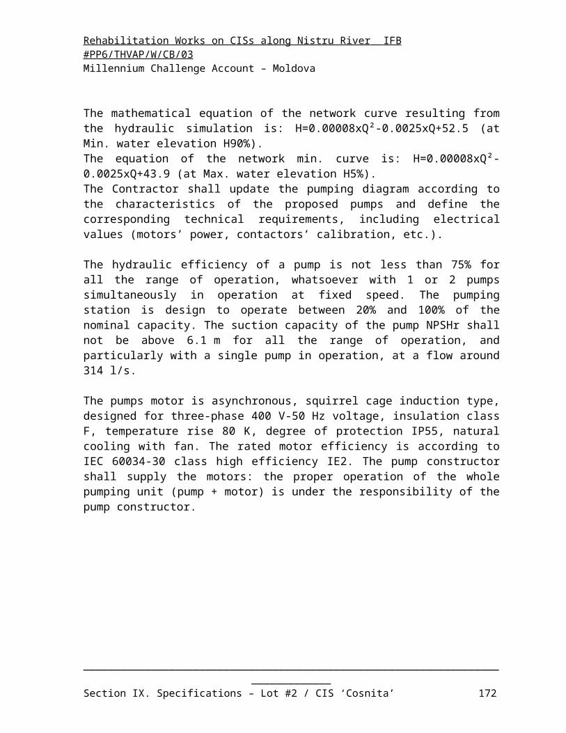
Rehabilitation Works on CISs along Nistru River IFB #PP6/THVAP/W/CB/03 Millennium Challenge Account – Moldova
o 1 emergency stop «punch» button fail-safe wired disposed according to the regulation.
_________________________________________________________________________________Section IX. Specifications – Lot #2 / CIS ‘Cosnita’ 172

Rehabilitation Works on CISs along Nistru River IFB #PP6/THVAP/W/CB/03 Millennium Challenge Account – Moldova
7.4 AUTOMATION AND SCADA SYSTEM
7.4.1 Instrumentation and metering
The instrumentation and metering devices at the pumping station have the following characteristics:
o 1 level sensor transmitting analogical signal in the river, for water level measurement. The device includes sensor/transmitter and suitable transducer into 4-20 mA signal as input into the PLC. The distance between sensor and PLC shall be considered. The level for alarm transmission is as follows: 7.78 m, which corresponds to 90% of the ranked flows in the river;
o 4 pressure sensor/transmitters with analogical signals installed on the discharge pipes of each pump, for pressure measurement. They deliver measurement values of the discharge pressure at each pump. These sensors/transmitters delivers 4-20 mA signal as input into the PLC;
o 4 pressure gauges downstream the pumps;
o 4 pressure gauges downstream the discharge gate valves;
o 1 double pressure switch with digital signals installed on the discharge main pipe of SP-4A, for pressure detection. It shall switch if the discharge pressure is too low or too high. The pressure for alarms transmission is 1 bar above and below the extremes values of the discharge curve shown on the pump diagram:
- 58 m = 5.7 bars: high pressure alarm;
- 13 m = 1.3 bars: low pressure alarm;
o 1 double pressure switch with digital signals installed on the discharge main pipe of SP-4B, for pressure detection. It shall switch if the discharge pressure is too low or too high. The pressure for alarms transmission is 1 bar above and below the extremes values of the discharge curve shown on the pump diagram:
- 68 m = 6.7 bars: high pressure alarm;
- 19 m = 1.9 bars: low pressure alarm;
o 1 pressure sensor/transmitter with analogical signals installed on each discharge main pipe, for pressure measurement. It delivers measurement values of the discharge pressure at the pumping station outlet. The transmitter shall be installed in or near the manhole for local monitoring and shall deliver the information as 4-20 mA for the PLC;
_________________________________________________________________________________Section IX. Specifications – Lot #2 / CIS ‘Cosnita’ 173

Rehabilitation Works on CISs along Nistru River IFB #PP6/THVAP/W/CB/03 Millennium Challenge Account – Moldova
o 1 ultrasonic flow-meter with analogical signal installed in the manhole on each discharge main pipe, for water flow measurement and integration capability to count and store the data of water volumes taken from the river and delivered to the irrigation network. The flow meter will be of a type and model approved for use in Moldova for billing purpose. It delivers measurement values of the discharge flow at the pumping station. The transmitter shall be installed in or near the manhole for local monitoring and shall deliver the information as 4-20 mA for the PLC. Two indicators for flow and volumes are installed: one in the manhole and the other on the front door of the automation switch gear;
o 6 conductive water level switches with digital signal installed in the drainage sump pit, for water level detection. They deliver 4 water regulation signals and alarm signals if the water level is too low or too high. The level for signal transmission is as follows:- - 3.24 m: high level alarm;- - 3.29 m: Start pump Nr. 2;- - 3.39 m: Start pump Nr. 1;- - 3.49 m: Stop pump Nr. 2;- - 3.54 m: Stop pump Nr. 1;- - 3.59 m: low level alarm;
o 6 conductive water level switches with digital signal installed in each pressure vessel, for water level detection. They deliver 4 water regulation signals and alarm signals if the water level is too low or too high.
For SP-4A, the level for signal transmission is as follows from the bottom (for a vertical vessel height 2,200 mm):- 1.93 m: high level alarm;- 1.88 m: Start compressor Nr. 2;- 1.83 m: Start compressor Nr. 1;- 1.78 m: Stop compressor Nr. 2;- 1.73 m: Stop compressor Nr. 1;- 0.60 m: low level alarm;
For SP-4B, the level for signal transmission is as follows from the bottom (for a vessel ND 1,500 mm):- 1.20 m: high level alarm;- 1.15 m: Start compressor Nr. 2;- 1.10 m: Start compressor Nr. 1;- 1.05 m: Stop compressor Nr. 2;- 1.00 m: Stop compressor Nr. 1;- 0.90 m: low level alarm;
o 3 temperature sensors with analogical signals, the first installed in the pumping room, the second in the electrical room and the third outside the building, for temperature measurement. They deliver measurement values in 4-20 mA to a transducer that allows converting the information of the temperature at each location.
_________________________________________________________________________________Section IX. Specifications – Lot #2 / CIS ‘Cosnita’ 174

Rehabilitation Works on CISs along Nistru River IFB #PP6/THVAP/W/CB/03 Millennium Challenge Account – Moldova
7.4.2 Automation and Control philosophy
7.4.2.1 Operating modes
The pumping station can be operated in 3 different modes:
o Local manual mode: through the remote control panels and the cabinet for ancillaries. This level of control is widespread. The control is performed by switches in general 3-positions "Manual - 0 - Auto", push buttons "Start" - "Stop" or "Open" - "Close" for equipment controlled by the PLC. The hard wire basic safety devices are active for this mode (protections of the motor protection relay, temperatures in the motor windings or pump bearings, starting frequency, etc.);
o Local automatic mode: command through the PLC Human Machine Interface (HMI). The pumping station can run fully automatically. This level enable to have an overview of the status of the equipment, of alarms, to visualize measured values;
o Remote control mode: no commands through the remote control centre are foreseen. The dispatching centre will have only monitoring and data processing and storage functions. Data will be displayed on a screen of the supervision computer. At this level will also be performed the functions of alarm management, editing, archiving, diagnostic and maintenance support.
7.4.2.2 Control philosophy
The regulation of the pumping station is made according to the water flow and the pressure required by the irrigation devices. The flow/pressure equation of the network resulting from the hydraulic simulation is:
For SP-4A: H=0.0011xQ²+0.013xQ+31.6; For SP-4B: H=0.000255xQ²-0.0109xQ+37.8.
When the water level in the river is at its low level (7.78 m corresponding to Min. water elevation H90%).
The number of operating pumps and the frequency drive of the motor will be determined to follow this network curve, minus the actual level measured by the level sensor in the river. For instance, if the water level is 1 m higher than the low level (8.78 m), the flow/pressure equation will be:
For SP-4A: H=0.0011xQ²+0.013xQ+31.6-1=0.0011xQ²+0.013xQ+30.6; For SP-4B: H=0.000255xQ²-0.0109xQ+37.8-1=0.000255xQ²-0.0109xQ+36.8.
The determination of the flow/pressure equation according to the river level shall be made once a day when the pumping station is started or at 8:00 if it was not stopped the day before.
_________________________________________________________________________________Section IX. Specifications – Lot #2 / CIS ‘Cosnita’ 175

Rehabilitation Works on CISs along Nistru River IFB #PP6/THVAP/W/CB/03 Millennium Challenge Account – Moldova
The system is designed to supply water between 20% and 100% of the rated flow. The pumping station shall be stopped if the measured flow goes under 20%.
The adjustable parameter below shall be adjusted at the HMI of the PLC.The status change of the different sensors must remain during 5 s (adjustable temporization for each sensor) before the PLC undertakes an action.
The instruction for manual starting of pumping station operation is as follows: Check that all relevant equipment (water hammer system, vacuum pump sytem,
pumps, valves, electrical supply, instrumentation and control, etc. ) is available; Assure that the selector switches of the pumps and the vacuum system is in manual
mode and of the other equipment is in automatic mode; Assure that the discharge valve is closed; Check that the water level measurement in the river is not triggered with alarm signal
for low level; Switch the vacuum system into automatic mode to depressurize all the suction pipes :
the vacuum pumps are operating until the beginning of the regulation phase (1st stop of all vacuum pumps indicating that the water raised the upper part of the vacuum tank);
Fill the main delivery pipe with water by starting one pump in manual mode (if it is not already filled). Some of the most distant hydrants have to be open. The gate valve downstream the operating pump has to be open at 25% to maintain a counter-pressure (monitored at the gauge) to create a head loss and enable a smooth filling;
Open a minimum of 20% of the hydrants; Open completely the gate valve downstream the operating pump; Switch the pump to automatic mode. The VFD shall automatically adjust its
frequency to reach the set point corresponding to the flow after checking that the double pressure switch on the main delivery pipe indicates that the pipe is full of water;
The water hammer system starts in automatic mode: the compressors are operating until the beginning of the regulation phase (1st stop of all compressors indicating that the air raised the lower part of the pressure vessel);
The regulation phase of the pumps begins.
The particular automatic control philosophy for the vacuum system is as follows:
oAssure that the selector switch of the vacuum system is in automatic mode;
o Check that the water level switch in the vacuum tank is not triggered with alarm signal for high water level;
o Select the vacuum pump Nr. to operate according to the last pump which was in operation: the other pump is selected;
o Start the vacuum pump;
_________________________________________________________________________________Section IX. Specifications – Lot #2 / CIS ‘Cosnita’ 176

Rehabilitation Works on CISs along Nistru River IFB #PP6/THVAP/W/CB/03 Millennium Challenge Account – Moldova
oWait until the water level switch to stop the pump is triggered. If it is not triggered after 30 min (adjustable parameter), start the second vacuum pump. Stop the second vacuum pump when the corresponding water level switch is triggered;
o Regulate the stop and start of the first vacuum pump according to the activation of the corresponding water level switches;
oWhen the pump planned is not available (in "Manual" or "0" position or in default) the other available pump shall start.
The particular automatic control philosophy for the water hammer system is as follows:
oAssure that the selector switch of the water hammer system is in automatic mode;
o Check that the water level switch in the pressure vessel is not triggered with alarm signal for low water level;
o Select the compressor Nr. to operate according to the last compressor which was in operation: the other compressor is selected;
o Start the compressor;
oWait until the water level switch to stop the compressor is triggered in the pressure vessel. If it is not triggered after 30 min (adjustable parameter), start the second compressor;
o Regulate the stop and start of the compressor according to the activation of the corresponding water level switches in the pressure vessel;
oWhen the compressor planned is not available (in "Manual" or "0" position or in default) the other available compressor shall start.
The particular automatic control philosophy of starting a pump in automatic mode is as follows:
oAssure that the selector switch of the pump is in automatic mode;
oAlternate the pump to start according to the last pump which was in operation: the other pump is selected;
o Check that the positions’ switch of the gate valve downstream the pump is triggered on the "Close" position. If it is not triggered, launch a "close" order of the valve and wait until the positions’ switch is triggered on the "Close" position;
o Close the valve of the vacuum pipe for priming the pump;
o Start the pump at minimum speed (i.e. 60% of the rated frequency) and increase the speed gradually;
o Increase the speed until the discharge pressure sensor of the pump delivers a measured value equal to the minimum pressure according to the equation of the network curve:
_________________________________________________________________________________Section IX. Specifications – Lot #2 / CIS ‘Cosnita’ 177

Rehabilitation Works on CISs along Nistru River IFB #PP6/THVAP/W/CB/03 Millennium Challenge Account – Moldova
- For SP-4A: 23 m = 2.3 bars, adjustable parameter;
- For SP-4B: 29 m = 2.9 bars, adjustable parameter;
oOpen the gate valve downstream the pump and wait until the positions’ switch is triggered on the "Open" position;
oAnother pump cannot be started before the end of this sequence;
o Begin the regulation phase:
- According to the water flow measured by the flow-meter, accelerates or decelerates the frequency controlled drive to reach the pressure of the set point calculated with the flow/pressure equation. This pressure is measured by the pressure sensor of the discharge main pipe. The set point is calculated every 30 s (adjustable parameter) and implemented with the Proportional/Integral/Derivative function of the PLC (PID controller);
- If the required pressure cannot be reached after 30 s (adjustable parameter) at the maximum frequency reduce the speed of the pump to the minimum frequency (i.e. 60% of the rated frequency) and start the other pump at the minimum frequency;
- According to the water flow measured by the flow-meter, accelerates or decelerates the frequency drive of both pumps at the same speed to reach the pressure of the set point calculated with the flow/pressure equation;
- If the required water flow is reduced to 90 l/s for SP-4A (adjustable parameter) or 230 l/s for SP-2B (adjustable parameter), the first running pump will be stopped and the other shall be set to its maximum speed before decelerating to meet the pressure of the set point;
o Check each 60 s (adjustable parameter) that the double pressure switch installed on the discharge main pipe is not out of the limits (see the chapter "Instrumentation and metering");
oA cool down time set for 10 min (adjustable parameter) will be used to ensure that the pump cools down after each stop prior to automatic restart based on the flow in the network. This can be by-passed by the operator if required by using the push-button "Default reset" on the motor starter switchboard;
oWhen the pump planned is not available (in "Manual" or "0" position or in default) another available pump shall start.
o If the VFD is out of order, it can be manually by-passed using the double switches provided for this purpose. When the pump station will be switched in the automatic mode again a pump with VFD will be first selected and the following regulation phase will be implemented:
_________________________________________________________________________________Section IX. Specifications – Lot #2 / CIS ‘Cosnita’ 178

Rehabilitation Works on CISs along Nistru River IFB #PP6/THVAP/W/CB/03 Millennium Challenge Account – Moldova
- According to the water flow measured by the flow-meter, accelerates or decelerates the frequency drive to reach the pressure of the set point calculated with the flow/pressure equation. This pressure is measured by the pressure sensor of the discharge main pipe. The set point is calculated every 30 s (adjustable parameter) and implemented with the Proportional/Integral/Derivative function of the VFD (PID controller);
- If the required pressure cannot be reached after 30 s (adjustable parameter) at the maximum frequency start the other pump;
- Reduce the speed of the former pump to the minimum frequency (i.e. 60% of the rated frequency);
- According to the water flow measured by the flow-meter, accelerates or decelerates the frequency drive of the pump to reach the pressure of the set point calculated with the flow/pressure equation;
- If the required water flow is reduced to 90 l/s for SP-4A (adjustable parameter) or 230 l/s for SP-4B (adjustable parameter), the running pump with fixed speed will be stopped;
The sequence of stopping a pump is as follows:
o Stop the pump;
o Close the gate valve downstream the pump and wait until the positions’ switch is triggered on the "Closed" position;
oOpen the valve of the vacuum pipe for priming the pump.
The particular automatic control philosophy for the drainage system is as follows:
o Check that the water level switch in the drainage sump pit is not triggered with alarm signal for low water level;
o Select the pump Nr. to operate according to the last pump which was in operation: the other pump is selected;
o Start the drainage pump when the corresponding water level switch is triggered;
o Start the second drainage pump when the corresponding water level switch is triggered;
o Regulate the stop and start of the 2 drainage pumps according to the activation of the corresponding water level switches;
oWhen the pump planned is not available (in "Manual" or "0" position or in default) the other available pump shall start.
The automatic particular control philosophy for the ventilation system is as follows:
oAssure that the selector switch of the fan is in automatic mode;
oA fan is dedicated to 1 or 2 pumps;
_________________________________________________________________________________Section IX. Specifications – Lot #2 / CIS ‘Cosnita’ 179

Rehabilitation Works on CISs along Nistru River IFB #PP6/THVAP/W/CB/03 Millennium Challenge Account – Moldova
o Start a fan when the following conditions are reached together:
- One of the corresponding pumps is operating;
- The temperature sensor in the pumping room indicates more than 25°C (adjustable parameter);
- The temperature sensor in the pumping room indicates more than the temperature sensor outside the building;
oWhen the fan planned is not available (in "Manual" or "0" position or in default) another available fan shall start;
Stop a fan when one of the following conditions is reached:
oAll the corresponding pumps are stopped;
o The temperature sensor in the pumping room indicates less than 20°C (adjustable parameter);
o The temperature sensor in the pumping room indicates less than the temperature sensor outside the building.
7.4.2.3 Processing failure and alarms
o In case of processed values out of their normal range, an alarm will be sent to the SCADA system: low level in the river, flood in pumping room, high and low pressure in the main discharge pipe. The pumps will not start or will be stopped with a 30 s delay between each (adjustable parameter);
o In case of flow meter failure an alarm will be sent to the SCADA system and the pumps will be stopped with a 30 s delay between each (adjustable parameter). They can be used in manual mode;
o In case of pressure sensor failure on the main pipe an alarm will be sent to the SCADA system and the pumps will be stopped with a 30 s delay between each (adjustable parameter). They can be used in manual mode;
o In case of high alarm in the vacuum tank, the vacuum pumps will be stopped until the water level reaches the start level of the 1st vacuum pump. In case of low alarm in the vacuum tank an alarm will be sent to the SCADA system and the system remains in operation;
o In case of low alarm in the pressure vessel, the compressors will be stopped until the water level reaches the start level of the 1st compressor. If it’s not the case after 60 s (adjustable parameter) the solenoid valve of the pressure vessel will be open until the water level reach the start level. In case of high alarm in the pressure vessel an alarm will be sent to the SCADA system and the system remains in operation;
_________________________________________________________________________________Section IX. Specifications – Lot #2 / CIS ‘Cosnita’ 180

Rehabilitation Works on CISs along Nistru River IFB #PP6/THVAP/W/CB/03 Millennium Challenge Account – Moldova
o In case of VFD failure, the double switches can be manually switched to the direct starting position. A global defect alarm for pump will be sent to the SCADA system;
o In case of failure of pump, dewatering pump and compressor, it will be stopped and the other standby similar equipment will automatically be started instead of the former one. A global defect alarm for the corresponding equipment will be sent to the SCADA system. If no standby equipment is available the pumps will be stopped with a 30 s delay between each (adjustable parameter);
o In case of any failure on other device, it will be stopped as well as further actions and an alarm will be sent to the SCADA system: global defect for pump and corresponding valves, for the vacuum system, for the drainage system, for the water hammer system, for the ventilation system. The pumps will be stopped with a 30 s delay between each (adjustable parameter);
o In case of total power failure of less than 1 s (adjustable parameter), the pumping station will restart automatically. If the power failure is of more than 1 s, all the equipment shall be stopped and the pumping station has to be restart by manual action as described in the instruction for manual starting of pump operation.
7.4.2.4 Processing data and curves
The PLC shall provide the following data and curves:
oDaily water flow Q (m3/h and l/s) with a step of 1 hour (adjustable parameter);
oDaily water volume (m3) with a step of 1 hour (adjustable parameter) and cumulated value;
oDaily water level in the river H (m) with a step of 1 hour (adjustable parameter);
oDaily discharge pressure P (bars) with a step of 1 hour (adjustable parameter);
oDaily hydraulic power consumption (kWh) = 9.81 x Q x P with a step of 1 hour (adjustable parameter) and cumulated value;
oDaily electrical power consumption (kWh) = √3 x U x I x cos φ, with φ = arctan (reactive power/active power) with a step of 1 hour (adjustable parameter) and cumulated value;
oDaily system efficiency (hydraulic power/electrical power) with a step of 1 hour (adjustable parameter) and cumulated value;
oDaily electrical power consumption / water volume (kWh/m3) with a step of 1 hour (adjustable parameter) and cumulated value;
oMonthly water flow (m3/h and l/s) with a step of 1 day;
oMonthly water volume (m3) with a step of 1 day and cumulated value;
oMonthly water level in the river H (m) with a step of 1 day;
_________________________________________________________________________________Section IX. Specifications – Lot #2 / CIS ‘Cosnita’ 181

Rehabilitation Works on CISs along Nistru River IFB #PP6/THVAP/W/CB/03 Millennium Challenge Account – Moldova
oMonthly discharge pressure data (bars) with a step of 1 day;
oMonthly hydraulic power consumption (kWh) = 9.81 x Q x H with a step of 1 day and cumulated value;
oMonthly electrical power consumption (kWh) = √3 x U x I x cos φ, with φ = arctan (reactive power/active power) with a step of 1 day and cumulated value;
oMonthly system efficiency (hydraulic power/electrical power) with a step of 1 day and cumulated value;
oMonthly electrical power consumption / water volume (kWh/m3) with a step of 1 day and cumulated value.
oAnnual water flow (m3/h and l/s) with a step of 1 month;
oAnnual water volume (m3) with a step of 1 month and cumulated value;
oAnnual water level in the river H (m) with a step of 1 month;
oAnnual discharge pressure data (bars) with a step of 1 month;
oAnnual hydraulic power consumption (kWh) = 9.81 x Q x H with a step of 1 month and cumulated value;
oAnnual electrical power consumption (kWh) = √3 x U x I x cos φ, with φ = arctan (reactive power/active power) with a step of 1 month and cumulated value;
oAnnual system efficiency (hydraulic power/electrical power) with a step of 1 month and cumulated value;
oAnnual electrical power consumption / water volume (kWh/m3) with a step of 1 month and cumulated value.
7.4.3 PLC input /output
The PLC input / output comprises of (not limited to):
_________________________________________________________________________________Section IX. Specifications – Lot #2 / CIS ‘Cosnita’ 182

Rehabilitation Works on CISs along Nistru River IFB #PP6/THVAP/W/CB/03 Millennium Challenge Account – Moldova
DesignationANA
.I
DIG.I
ANA.O
DIG.O
General incoming and protection switch gear 4 5 0 2Presence of voltage from the main power 1 1Circuit breaker opening from the main power 1 Default from input voltages and currents 1 1Data-logger: voltage, current, active and reactive power 4 Default reset 1 Emergency stop 1 Automatic plant for reactive power compensation 0 1 0 1Default from automatic plant for reactive power compensation 1 1 Secondary incoming and protection switch gear 0 3 0 2Presence of voltage from the secondary power 1 1Circuit breaker opening from the secondary power 1 Default from input voltages and currents 1 1 Motor starter switch gear VFD (x4) 12 32 8 24Presence of voltage 1 1Default reset 1 Default VFD 1 Setpoint VFD (automatic) 1 Setpoint VFD (manual) 1 Returned information from VFD 1 Order start pump 1Order stop pump 1Pump is operating 1 1Default Motor Protection Relay 1Bearing temperature 1 Stator winding temperature 1 Position of by-pass of the VFD 1 1Selector switch position "Auto" for the pumps operating 1 Selector switch position "Manu" for the pumps operating 1 Emergency stop 1 Switch- and control gear for ancillaries 0 70 0 78Presence of voltage 1 1Default reset 1 Order start compressor n°1-2 2Order stop compressor n°1-2 2compressor n°1-2 is operating 2 2
_________________________________________________________________________________Section IX. Specifications – Lot #2 / CIS ‘Cosnita’ 183

Rehabilitation Works on CISs along Nistru River IFB #PP6/THVAP/W/CB/03 Millennium Challenge Account – Moldova
Default compressor n°1-2 2 2Order open water hammer system valve 1Water hammer system valve is opened 1 1Order close water hammer system valve 1Water hammer system valve is closed 1 1Default water hammer system valve 1 1Selector switch position "Auto" for the compressor n°1-2 operating 2 Selector switch position "Manu" for the compressor n°1-2 operating 2 Order start vacuum pump n°1-2 2Order stop vacuum pump n°1-2 2Vacuum pump n°1-2 is operating 2 2Default vacuum pump n°1-2 2 2Order open vacuum system valve n°1-4 4Vacuum system valve n°1-4 is opened 4 4Order close vacuum system valve n°1-4 4Vacuum system valve n°1-4 is closed 4 4Default vacuum system valve n°1-4 4 4Selector switch position "Auto" for the vacuum pump n°1-2 operating 2 Selector switch position "Manu" for the vacuum pump n°1-2 operating 2 Order open main valve n°1-4 4Main valve n°1-4 is opened 4 4Main valve n°1-4 overtorque at opening 4 Order close main valve n°1-4 4Main valve n°1-4 is closed 4 4Main valve n°1-4 overtorque at closing 4 Order stop main valve n°1-4 4Default main valve n°1-4 4 4Order start Fan n°1-3 3Fan n°1-3 is operating 3 3Order start fan electrical room 1Fan electrical room is operating 1 1Default fan n°1-3 3 3Default fan electrical room 1 1Selector switch position "Auto" for the fan n°1-3 operating 3 Selector switch position "Manu" for the fan n°1-3 operating 3 Selector switch position "Auto" for the fan electrical room operating 1 Selector switch position "Manu" for the fan electrical room operating 1 Emergency stop 1
_________________________________________________________________________________Section IX. Specifications – Lot #2 / CIS ‘Cosnita’ 184

Rehabilitation Works on CISs along Nistru River IFB #PP6/THVAP/W/CB/03 Millennium Challenge Account – Moldova
Command, Automation and remote control switch- and control gear 11 28 0 16Presence of voltage 1 1Default reset 1 Presence of voltage from Uninterruptible Power Supply 1 1Default Uninterruptible Power Supply 1 1Default from the Programmable Logic Controller 1Default from the Remote Terminal Unit 1 1Measurement of flow-meter 1 Measurement of water level in the river 1 Alarm low water level in the river 1Pressure in the main pipe 2 Pressure in the discharge pipe pump n°1-4 4 Low pressure in the discharge main pipe 2 High pressure in the discharge main pipe 2 Alarm low pressure in the discharge main pipe 2Alarm high pressure in the discharge main pipe 2Water level in the drainage sump pit 6 Alarm water level in the drainage sump pit 2Water level in the vacuum tank 6 Alarm water level in the vacuum tank 2Water level in the pressure vessel 6 Alarm water level in the pressure vessel 2Temperature in the pumping room 1 Temperature in the electrical room 1 Temperature outside de building 1 Emergency stop 1 Lighting and sockets switch gear 0 24 0 24Order start drainage pump n°1-2 2Order stop drainage pump n°1-2 2Drainage pump n°1-2 is operating 2 2Default drainage pump n°1-2 2 2Selector switch position "Auto" for the drainage pump n°1-2 operating 2 Selector switch position "Manu" for the drainage pump n°1-2 operating 2 Local control panels for the main pumps (x4) 0 24 0 24Signaling presence of voltage 1Signaling pump is operating 1Signaling default Motor Protection Relay 1Push-button "Start" to start the pump 1
_________________________________________________________________________________Section IX. Specifications – Lot #2 / CIS ‘Cosnita’ 185

Rehabilitation Works on CISs along Nistru River IFB #PP6/THVAP/W/CB/03 Millennium Challenge Account – Moldova
Push-button "Stop" to stop the pump 1 Signaling main valve is opened 1Signaling main valve is closed 1Signaling default main valve 1Push-button "Open" to open the main valve 1 Push-button "Stop" to stop the main valve 1 Push-button "Close" to close the main valve 1 Emergency stop 1 Local control panel for the vacuum system 0 13 0 17Signaling presence of voltage 1Signaling vacuum pump n°1-2 is operating 2Signaling default vacuum pump n°1-2 2Push-button "Start" to start the vacuum pump n°1-2 2 Push-button "Stop" to stop the vacuum pump n°1-2 2 Signaling vacuum system valve n°1-4 is opened 4Signaling vacuum system valve n°1-4 is closed 4Signaling default vacuum system valve n°1-4 4Push-button "Open" to open the vacuum system valve n°1-4 4 Push-button "Close" to close the vacuum system valve n°1-4 4 Emergency stop 1 Local control panel for the drainage pumps 0 5 0 5Signaling presence of voltage 1Signaling drainage pump n°1-2 is operating 2Signaling default drainage pump n°1-2 2Push-button "Start" to start the drainage pump n°1-2 2 Push-button "Stop" to stop the drainage pump n°1-2 2 Emergency stop 1 Local control panel for the water hammer protection system 0 7 0 8Signaling presence of voltage 1Signaling compressor n°1-2 is operating 2Signaling default compressor n°1-2 2Push-button "Start" to start the compressor n°1-2 2 Push-button "Stop" to stop the compressor n°1-2 2 Signaling water hammer protection system valve is opened 1Signaling water hammer protection system valve is closed 1Signaling default water hammer protection system valve 1Push-button "Open" to open the water hammer system valve 1 Push-button "Close" to close the water hammer system valve 1 Emergency stop 1
_________________________________________________________________________________Section IX. Specifications – Lot #2 / CIS ‘Cosnita’ 186

Rehabilitation Works on CISs along Nistru River IFB #PP6/THVAP/W/CB/03 Millennium Challenge Account – Moldova
Analog Inputs : 27 Digital Inputs : 212
Analog Outputs : 8 Digital Outputs : 201
_________________________________________________________________________________Section IX. Specifications – Lot #2 / CIS ‘Cosnita’ 187

Rehabilitation Works on CISs along Nistru River IFB #PP6/THVAP/W/CB/03 Millennium Challenge Account – Moldova
7.4.4 Supervisory Control And Data Acquisition system (SCADA)
7.4.4.1 Structure of the system The SCADA system is essentially defined by:
o The instrumentation, metering devices and sensors in some equipment (see the chapters above), which determines information to be transmitted;
o The PLC in each pumping station;o The number and distribution of the Remote Terminal Units (RTU):
- At the SP-1 pumping station;
- At the SP-2 pumping station;
- At the SP-3A pumping station;
- At the SP-4 pumping station;
The transmission media: GSM data – GPRS; The supervisory station at the remote control center (1 for Cosnita irrigation scheme)
equipped with:o A frontal communication device for remote transmission of the various Remote
Terminal Units:
- Query of the different RTU;
- Decoding the information;
- Information storage buffer before transmission to the supervisory computer;
- Serial link with the supervisory computer following an adapted protocol;
- Remote transmission of various Remote Terminal Units;
o A supervisory computer with a software for piloting of all associated Remote Terminal Units, displaying synoptic screens, managing the data and to emit alarms:
- Piloting of all associated RTU;
- Synoptic display screen;
- Data management (statistical treatments);
- Defect management (statistical treatments);
- Operating assistance (edition of logbooks);
- Management of the graphics printer;
o A printer for edition of logbooks;o An on-call terminal to alert operators in case of alarm, generating automatically
an SMS using the wording of the defect;o An Uninterruptible Power Supply (UPS) 50 Ah.
_________________________________________________________________________________Section IX. Specifications – Lot #2 / CIS ‘Cosnita’ 188

Rehabilitation Works on CISs along Nistru River IFB #PP6/THVAP/W/CB/03 Millennium Challenge Account – Moldova
7.4.4.2 Remote Terminal Units
This unit handles all remote transmissions with the Supervisory Station at the control center. It receives information directly from the PLC.
The Remote Terminal Units provide the following main functions:o Acquisition, filtering, timing information to their appearance or status change;o Storage buffer before remote transmission;o Coding and addressing information in accordance with the protocol for remote
transmission. These facilities are equipped with a self-diagnosis system type "watchdog". Each RTU will be equipped with modems for GSM data - GPRS communication,
which is used as interface between the communication network and the Remote Terminal Unit.
7.4.4.3 Remote controlled parameters
The following information will be exchanged through the SCADA system by status change:o Power failure in the pumping station: main circuit breaker opening, lack of
tension, phase inversion, etc.);o Operational status of the command: "Manual - 0 - Auto";o Operational status of each pump "On" - "Off";o Global defect for each pump: thermal load and max current, frequent starts,
temperature probes, etc.);o Global defect for the drainage system;o Global defect for the water hammer system;o Global defect for the ventilation system;o Water flows and volumes (once a day);o Water level alarms:
- Low level in the river;
- Flood in pumping room;
o Water level in the river (once a day);o Pressure alarms: high and low pressure in the main discharge pipe;o PLC failure;o RTU failure;o UPS failure.
_________________________________________________________________________________Section IX. Specifications – Lot #2 / CIS ‘Cosnita’ 189

Rehabilitation Works on CISs along Nistru River IFB #PP6/THVAP/W/CB/03 Millennium Challenge Account – Moldova
8 SPARE PARTS AND TOOLS
8.1 SPARE PARTS
8.1.1 Spare parts for pipe network
Manual gate valves: Complete valve: two (2) of each size; Packing: two (2) sets for each size; Body bonnet: two (2) sets for each size; Gaskets: 6 pieces for each size;
Air relief valves Complete valve: two (2) of each size; Floating ball: 6 pieces for each size; Signalling rod: 10 pieces;
Hydrants; Complete hydrant set including tee-piece, riser and valve: 1% of each type but not
less than 6 sets; Special hydrant valve set including gaskets, bolts, nuts and washers: 1% of each type
but not less than 6 pieces; Gaskets: 1% of each size but not less than 6 pieces;
HDPE Pipes; HDPE PE 100, NP 10, pipes sections of 9 m in length: 0.1% of each diameter but not
less than 6 sections of 9 m for each diameter;
8.1.2 Spare parts for pumping station
Pumps: Impeller and shaft: one unit per pump type Gland-packing: four sets per pump Packing ring : one Lantern ring : one Shaft sleeves : two per pump Bearings : two sets per pump Motor coupling: one set Recommended grease/oil sufficient for one year of operation Recommended casing sealant sufficient to provided seal the casing 10 times.
Ancillary equipment (vacuum pump, compressor):
_________________________________________________________________________________Section IX. Specifications – Lot #2 / CIS ‘Cosnita’ 190

Rehabilitation Works on CISs along Nistru River IFB #PP6/THVAP/W/CB/03 Millennium Challenge Account – Moldova
Bearings: one set; Wear rings: one set; Seals: two sets; Motor coupling: one set;
Manual Gate Valves: Packing: one set; Body bonnet: one; Gaskets: 3 pieces;
Motorised Gate Valves: Packing: one set; Body bonnet: one; Gaskets: 3 pieces; Gate position indicator: 3 pieces; Motor: one; Actuator: one.
Check (Non Return) Valves: one;
Sensors and transmitters: Water level: one piece; Pressure: one piece; Temperature: one piece; Differential pressure: one piece; Water level (detector) relay: 3 pieces;
Gauges: Pressure: one piece;
Electric ventilation air fans: Suction air filter panels: 1 per fan; Set of bearings (Support and gear): one; Impeller: two.
Air pressure vessels: Set gasket: one; Sight glass: two; Stud bolts with unit: complete set.
Electricity: 1 set of bearings for each type of motor; 1 pump circuit breaker of each type; 2 contactors of each type; 1 motors protective relay of each type; 5 auxiliary circuit breaker of each type;
_________________________________________________________________________________Section IX. Specifications – Lot #2 / CIS ‘Cosnita’ 191

Rehabilitation Works on CISs along Nistru River IFB #PP6/THVAP/W/CB/03 Millennium Challenge Account – Moldova
5 auxiliary contactor of each type; 1 ammeter; 1 voltmeter; 5 relays of each type; 5 timed relays of each type; 5 hour meters; 5push buttons of each type; 10 fuses of each type; 10signal lights of each type; 1 selector switch of each type 1 package of terminal blocks of each types 1 package wire for control wiring; 1 set of various push buttons, fuses, lamps, emergency stop, etc.; 1 power supply module of each type for PLC and RTU; 1 processor of each type for PLC and RTU; 1 memory card of each type for PLC and RTU; 1 communication card of each type for PLC and RTU; 2 digital input cards of each type for PLC and RTU; 1 analog input card for PLC; 2 digital output cards of each type for PLC and RTU; 1 analog output card for PLC; 1 GSM/GPRS modem; 1 portable autonomous lamp.
The Contractor should detail the lump sum assigned to these parts for each piece in an annex of its financial offer. He shall also indicate a list of supplier of these equipment in Moldova or in neighbouring countries
8.2 TOOLS
The contractor shall supply a set of tools and storage arrangements (tools boxes, cases, trolleys,...). The tools must of a size required to maintain and repair the equipment and be guaranteed by the manufacturer to be replaced in case of failure. The Contractor shall submit his proposal for the tools and storage arrangements to the Engineer for approval.
The tools shall include: Any special tools required for the operation, maintenance and repair of any of the
plant of the pumping station. Sets of flat, ring, box, Allen keys Adjustable keys Screw drivers, flat, cross,...as required Pliers as needed (flat, cutting, sur-clip, water pump, long nose, ...) pipe wrench, small and large Hammers Files
_________________________________________________________________________________Section IX. Specifications – Lot #2 / CIS ‘Cosnita’ 192

Rehabilitation Works on CISs along Nistru River IFB #PP6/THVAP/W/CB/03 Millennium Challenge Account – Moldova
Feeler gauges Multimeter (V-A-Ohm) Bearing puller Hoist 5 ton 5 m aluminium ladder Trolley Disk grinder Electrical drill with accessories for loosening/tightening nuts and screws Compressor with flexible pipe and air gun.
_________________________________________________________________________________Section IX. Specifications – Lot #2 / CIS ‘Cosnita’ 193

Rehabilitation Works on CISs along Nistru River IFB #PP6/THVAP/W/CB/03 Millennium Challenge Account – Moldova
9 ARCHITECTURAL/STRUCTURALWORKS IN THE PUMPING STATION
9.1 NEW PUMPING STATIONSTwo new pumping station buildings (SP1-SP3) will be constructed to replace/integrate the existing pressure pumping stations.
SP-1 building measures 14,8x7,8m and the total height is 5,0m. It is composed by an underground part (6,4m depth) containing the pumps made of concrete plates with 50 cm thickness and a steel upper-structure composed by three spans with 6 steel pillars (N°30 GOST 8239-89) and a transversal metal trestle (N°12 GOST 8239-89) on which is hooked the bridge crane (N°30 GOST 8239-89). In the central span has been designed a steel wind bracing. Floor plan is designed with a 15 thickness concrete plate supported by a rectangular concrete beam. The filling of exterior walls and the roof are made of sandwich panels of three layers 12 cm thickness fixed to the frame metallic structure. Adjacent to the building has been designed a electrical units room linked to the upper-structure of the major building with a metal trestle resting on two steel pillars (N°30 GOST 8239-89) based on concrete plinths.
SP-3 building measuring is 15,1x7,6m and the total height of 5,0m. The scheme of the structure is similar to SP-1 with an underground pumps room and a steel upper-structure with two spans. Also in this structure there is an electric units room adjacent to the main structure.
9.2 REHABILITATION WORKS
9.2.1 FLOORING
The Contractor shall demolish the existing floor in pumps room and the drainage sump pit up to a depth of 50 – 100 mm, as is shown on drawings. New floor shall be constructed as shown on drawings. The new floor shall be reinforced with a steel fabric (welded wire mesh of 3 mm in diameter and 200 x 200 mm the eye of mesh). The minimal cover of steel reinforcement shall be of 3 cm. The minimum thickness of the new concrete floor shall be of 150 mm. The finishing of the floor shall be of minimum 10 mm and maxim 50 mm of non-slip type. The finishing layer shall provide adequate slope to facilitate collection of water toward the drainage ditches, as shown on drawings. No concrete shall be cast in flooring before obtaining the approval of the Engineer.
9.2.2 FOUNDATIONS FOR PUMPS, MOTORS AND TANKS
The Contractor shall demolish the existing foundations for pumps, motors and tanks and all existing support structures for pipes and valves.
_________________________________________________________________________________Section IX. Specifications – Lot #2 / CIS ‘Cosnita’ 194

Rehabilitation Works on CISs along Nistru River IFB #PP6/THVAP/W/CB/03 Millennium Challenge Account – Moldova
The dimensions and materials provided on drawings for new foundations are meant just for a rough guidance of the Contractor but it is the Contractor’s responsibility to design and build adequate sized and strengthen foundations for all equipment.
Contractor shall designed and build new foundations for pumps, motors, and tanks according to the loads of each new equipment to be supplied on the site. The Contractor shall follow the instructions and regulations of the suppliers of pumps, motors and tanks to design adequate foundations and fixing for the new equipment. Structural calculations and detail design drawings including all dimensions and details needed for construction of new foundations shall be provided by the Contractor and submitted to the Engineer for approval. No concrete shall be cast in foundations before obtaining the approval of the Engineer.
The Contractor shall design and build adequate supports for pipes and valves wherever is needed.
9.2.3 WALL REPAIRING
The Contractor shall repair damaged wall inside and outside the pumping station building as shown and specified on drawings. The minimum cover of reinforcing steel bars and steel fabric shall be of 25 mm. Contractor shall submit to Engineer the methodology for crack filling for approval. All materials intended to be used by the Contractor for cracks filling and wall repairing are subject to Engineer’s approval.
9.2.4 DAMAGED CONCRETE REPAIRING
The Contractor shall repair damaged concrete of all structural elements inside and outside the pumping station building as shown and specified on drawings. The uncovered steel bars shall be cleaned of dust and rust. The minimum cover for the steel bars shall be on less than 25 mm. The repairing material shall be as shown on drawings or similar provided prior obtaining the approval of the Engineer. The Contractor may be asked by the Engineer to provide samples of concrete repairing before approval of materials and method for such repairing.
9.2.5 REINFORCEMENT OF THE BUILDING STRUCTURE
The Contractor shall build a reinforcement steel structure as shown on drawings (Reinforcement Rf5) and install it inside the pumping station building to provide enough strength to comply with the provision of local seismic norms.
Conformity and mill certificates for steel elements and welding rods as well as the welding method and welding testing method shall be submitted to the Engineer for approval before commencing the reinforcement works. Engineer may ask for Contractor to provide independent laboratory tests for any steel element to be used for building the reinforcement structures.
_________________________________________________________________________________Section IX. Specifications – Lot #2 / CIS ‘Cosnita’ 195

Rehabilitation Works on CISs along Nistru River IFB #PP6/THVAP/W/CB/03 Millennium Challenge Account – Moldova
9.2.6 JOINTS FILLING
All joints shall be filled as is shown on drawings. Proprietary materials may be used for filling of joints provided they are obtained from a source approved by the Engineer.
All jointing materials shall be used strictly in accordance with the manufacturers’ instructions.
9.2.7 WATERPROOFING
The Contractor shall use waterproofing layers as shown on drawings. Waterproofing materials shall be of type specified on drawings or similar provided that the prior approval of Engineer is obtained. Conformity certificates of waterproofing materials shall be submitted to the Engineer for approval before starting waterproofing works.
9.2.8 ROOF REPAIR AND INSULATION
Contractor shall remove all materials of the existing roof insulation and waterproofing and shall clean the roof concrete of dust and other contaminants.
Contractor shall repair and insulate the existing roof as is shown on drawings. Prior starting any roofing activity the Contractor shall submit and obtain the approval of the Engineer on the method and materials to be used for repair and waterproofing. The Contractor may use an equivalent waterproofing system provided that the prior approval of the Engineer is obtained. Sample areas of substrate shall be prepared and covered as required by the Engineer and for his approval. The Contractor may be asked by the Engineer to provide conformity certificates for materials intended to use for repair and waterproofing of the roof. The Contractor shall build the roof as shown in drawings respecting the slopes to facilitate the rain water removal. The rain water collection and removal system as indicated in drawings shall be built by the Contractor. Care should be taken to properly connect the rain water collection system to the waterproofing layers to avoid damage of the last.
_________________________________________________________________________________Section IX. Specifications – Lot #2 / CIS ‘Cosnita’ 196