particle collider interaction regions backgrounds and
TRANSCRIPT

PARTICLE COLLIDER INTERACTION REGIONS
Backgrounds and Machine-Detector Interface
Lecture 4: Collimation
USPAS
Hampton, VA
January 17-21, 2011
Nikolai Mokhov
Accelerator Physics Center
Fermilab
U.S. Particle Accelerator School Hampton, VA, 2011

USPAS, Hampton, VA, January 17-21, 2011 4. Collimation - N.V. Mokhov 2
OUTLINE
Collimation Basics Multi-Stage Scheme Collider Specifics e+e-
pp m+m-
Novel Techniques Crystals: Channeling, VR and VR
radiation Tail Folding with Non-Linear Optics Hollow e-Beam Lens

USPAS, Hampton, VA, January 17-21, 2011 4. Collimation - N.V. Mokhov 3
BEAM COLLIMATION
Beam collimation is mandatory at any high-power accelerator and hadron collider.
Only with a very efficient beam collimationsystem can one reduce uncontrolled beam lossesin the machine to an allowable level,
thus protect machine components, detectors andpersonnel against excessive irradiation, maintainoperational reliability over the life of the complex,provide acceptable hands-on maintenanceconditions, and reduce the impact of radiation onenvironment, both at normal operation andaccidental conditions.

USPAS, Hampton, VA, January 17-21, 2011 4. Collimation - N.V. Mokhov 4
COLLIMATION COMPLEXITY AND EFFICIENCY
Tevatron H&V collimators for proton (D49 primary, andE03, F172 and D173 secondary) and pbar (F49 primary,and F48 and D172 secondary) beams along with A01V andA48V for proton abort kicker prefire protection.Collimation efficiency is about 99.9%.
A brand new Main Injector system consists of a primarycollimator and 4 secondary collimators. The achievedefficiency is 99%. A new approach with integratedcollimator, marble shells and hybrid masks is used.
LHC Phase I system consists of 112 horizontal, verticaland skew collimators in the ring and SPS-LHC transferlines. A two-jaw opening at top energy is 3 mm. Surfaceroughness limit is about 25 mm. A design cleaningefficiency is 99.99%. A few novelties have recently beenimplemented.

USPAS, Hampton, VA, January 17-21, 2011 4. Collimation - N.V. Mokhov 5
COLLIMATOR AS A LAST LINE OF DEFENSE
All collimators must withstand a predefined fraction of the beam hittingtheir jaws and - at normal operation - survive for a time long enough toavoid very costly replacements.
0.5-MW, 2-mm diam e-beam,grazing on 60-cm Cu; it took 1.5 s to melt in
2-MJ 1-TeV p-beamdrilled a hole in Wprimary collimator,created a 1-ft groovein SS secondary one,and quenched 2/3 ofthe ring, all in a fewms. Abort systemfired in 10 ms.
USPAS, Hampton, VA, January 17-21, 2011 4. Collimation - N.V. Mokhov 6
TWO-STAGE BEAM COLLIMATION (1)
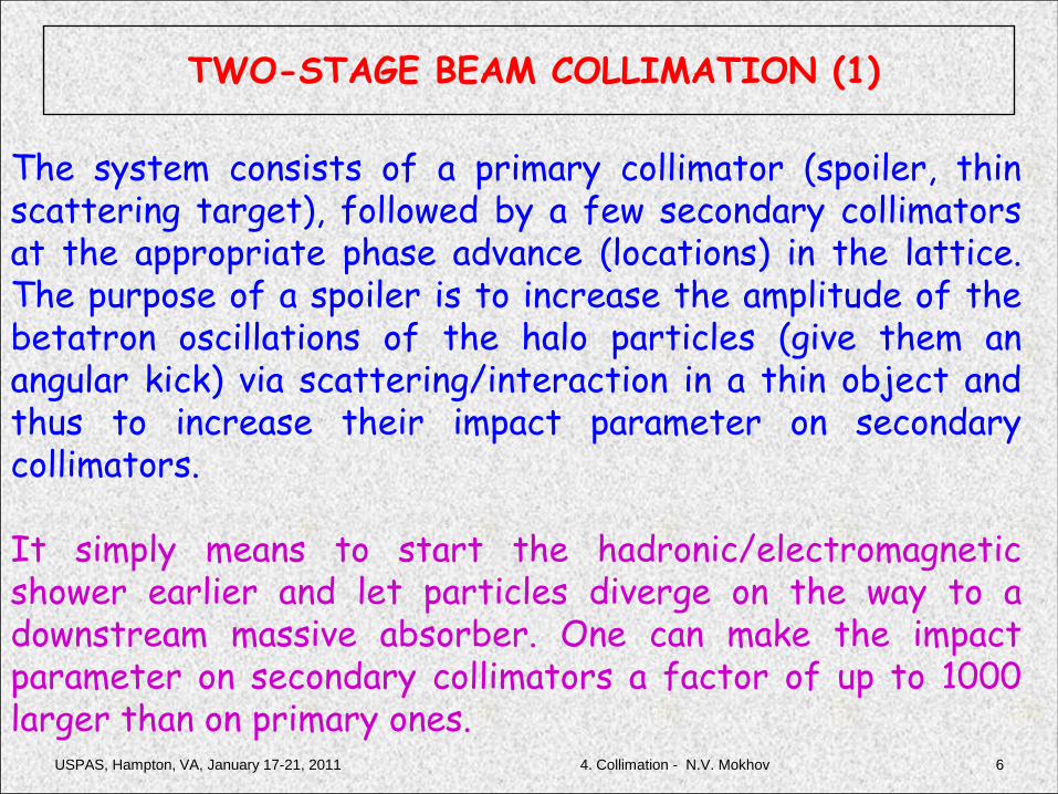
The system consists of a primary collimator (spoiler, thinscattering target), followed by a few secondary collimatorsat the appropriate phase advance (locations) in the lattice.The purpose of a spoiler is to increase the amplitude of thebetatron oscillations of the halo particles (give them anangular kick) via scattering/interaction in a thin object andthus to increase their impact parameter on secondarycollimators.
It simply means to start the hadronic/electromagneticshower earlier and let particles diverge on the way to adownstream massive absorber. One can make the impactparameter on secondary collimators a factor of up to 1000larger than on primary ones.

USPAS, Hampton, VA, January 17-21, 2011 4. Collimation - N.V. Mokhov 7
TWO-STAGE BEAM COLLIMATION (2)
This results in a significant increase of thecollimation efficiency: substantially lowerbackgrounds on detectors, beam loss in the lattice,and jaw overheating as well as easier collimatoralignment. With such a system, there are onlyseveral significant but totally controllablerestrictions of the machine aperture, withappropriate radiation shielding in these regions.
USPAS, Hampton, VA, January 17-21, 2011 4. Collimation - N.V. Mokhov 8
MULTI-STAGE COLLIMATION
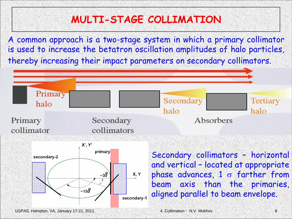
A common approach is a two-stage system in which a primary collimatoris used to increase the betatron oscillation amplitudes of halo particles,
thereby increasing their impact parameters on secondary collimators.
Secondary collimators – horizontaland vertical – located at appropriatephase advances, 1 s farther frombeam axis than the primaries,aligned parallel to beam envelope.

USPAS, Hampton, VA, January 17-21, 2011 4. Collimation - N.V. Mokhov 9
• The beam is very small => single bunch can punch a hole => the need for MPS (machine protection system)
• Damage may be due to
– electromagnetic shower damage (need several radiation lengths to develop)
– direct ionization loss (~1.5MeV/g/cm2
for most materials)
• Mitigation of collimator damage
– using spoiler-absorber pairs• thin (0.5-1 X0) spoiler followed by
thick (~20-30 X0) absorber
– increase of beam size at spoilers
– MPS diverts the beam to emergency extraction as soon as possible
Picture from beam damage experiment at FFTB.
The beam was 30GeV, 3-20x109 e-, 1mm bunch
length, s~45-200um2. Test sample is Cu, 1.4mm
thick. Damage was observed for densities >
7x10¹⁴e-/cm2. Picture is for 6x10¹⁵e-/cm2
MACHINE PROTECTION & COLLIMATOR DESIGN

USPAS, Hampton, VA, January 17-21, 2011 4. Collimation - N.V. Mokhov 10
MI Primary and Secondary Collimators
0.25-mm tungsten primary collimatorMI230
20-ton secondary collimator:4”x2” aperture, precise radialand vertical motion
Marble shell Poly mask

USPAS, Hampton, VA, January 17-21, 2011 4. Collimation - N.V. Mokhov 11
MI Steel/Concrete/Marble Masks and Wall
Steel/Concrete maskto capture outscatter
and neutrons
Steel/Marble maskto protect downstreammagnets
Concrete wall at 304to reduce neutronson ECOOL

USPAS, Hampton, VA, January 17-21, 2011 4. Collimation - N.V. Mokhov12
Operational Monitoring of MI Collimation Efficiency
Loss Time
Injection end
Uncaptured
Later
93% of uncapturedbeam loss is kept incollimation regionplus a few % lostimmediately dwnstrm
94.7% of injectedbeam acceleratedto extraction
BLM readings (rad/cycle), note three-decade log scale
It is now 99% !

USPAS, Hampton, VA, January 17-21, 2011
Collider Specifics: e+e-
134. Collimation - N.V. Mokhov
ILC

USPAS, Hampton, VA, January 17-21, 2011 4. Collimation - N.V. Mokhov 14
ILC BDS COLLIMATION SYSTEM
The system is designed to shave 0.1% of the beamintensity, and capable to withstand up to two fullerrant bunches.

USPAS, Hampton, VA, January 17-21, 2011 4. Collimation - N.V. Mokhov 15
• Halo must be collimated upstream in
such a way that SR g & halo e+- do not
touch VX and FD
• => VX aperture needs to be
somewhat larger than FD aperture
• Exit aperture is larger than FD or VX
aperture
• Beam convergence depends on
parameters, the halo convergence is
fixed for given geometry
=> qhalo/qbeam (collimation depth)
becomes tighter with larger L* or
smaller IP beam size
• Tighter collimation => MPS issues,
collimation wake-fields, higher muon
flux from collimators, etc.
Vertex
Detector
Final
Doublet (FD)
L*
IP
SR g
Beam
Halo
qbeam= e / s*
qhalo= AFD / L*
AFD
Even if final focus does not generate beam halo itself, the halo may come from upstream and need to be collimated
BEAM HALO & COLLIMATION (1)
USPAS, Hampton, VA, January 17-21, 2011 4. Collimation - N.V. Mokhov 16
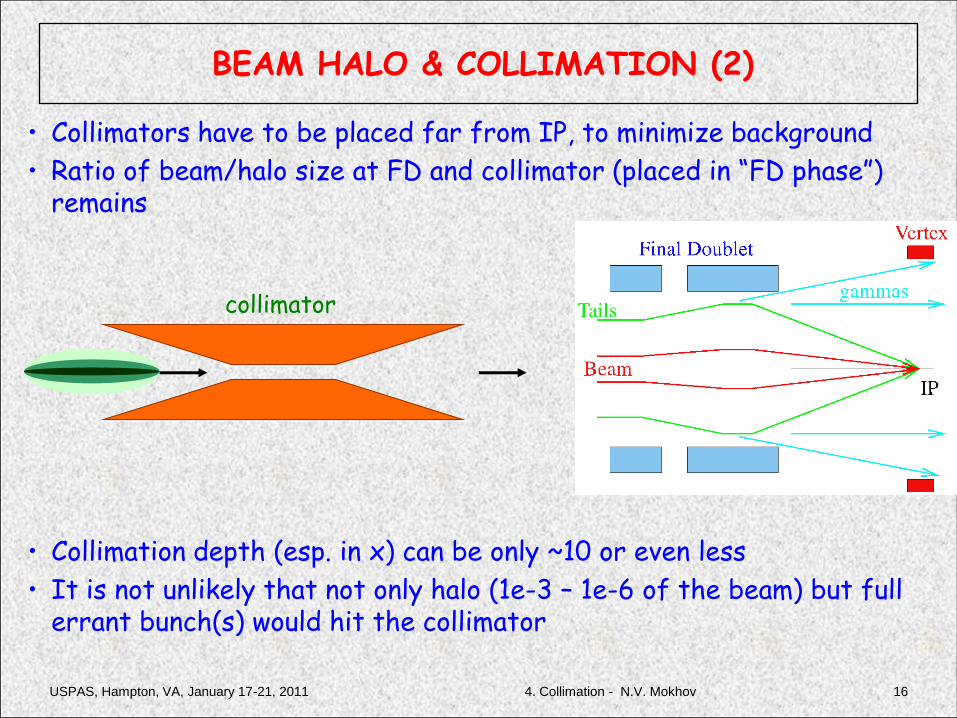
• Collimators have to be placed far from IP, to minimize background
• Ratio of beam/halo size at FD and collimator (placed in “FD phase”) remains
• Collimation depth (esp. in x) can be only ~10 or even less
• It is not unlikely that not only halo (1e-3 – 1e-6 of the beam) but full errant bunch(s) would hit the collimator
collimator
BEAM HALO & COLLIMATION (2)

USPAS, Hampton, VA, January 17-21, 2011 4. Collimation - N.V. Mokhov 17
Thin spoiler increases beam divergence and size at the thick absorber already sufficiently large. Absorber is away from the beam and contributes much less to wakefields.
Need the spoiler thickness increase rapidly, but need that surface to increase gradually, to minimize wakefields. The radiation length for Cu X0=1.43cm and for Be is X0=35cm. So, Be is invisible to beam in terms of losses. Thin one micron coating over Be provides smooth surface for wakes.
SPOILER-ABSORBER & SPOLIER DESIGN
USPAS, Hampton, VA, January 17-21, 2011 4. Collimation - N.V. Mokhov 18
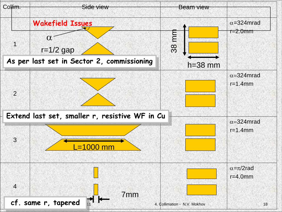
Collim. Side view Beam view
1
Wakefield Issues a=324mrad
r=2.0mm
2
a=324mrad
r=1.4mm
3
a=324mrad
r=1.4mm
4
a=p/2rad
r=4.0mm
h=38 mm
38
mm
L=1000 mm
7mm
a
r=1/2 gap
As per last set in Sector 2, commissioning
Extend last set, smaller r, resistive WF in Cu
cf. same r, tapered
USPAS, Hampton, VA, January 17-21, 2011 4. Collimation - N.V. Mokhov 19
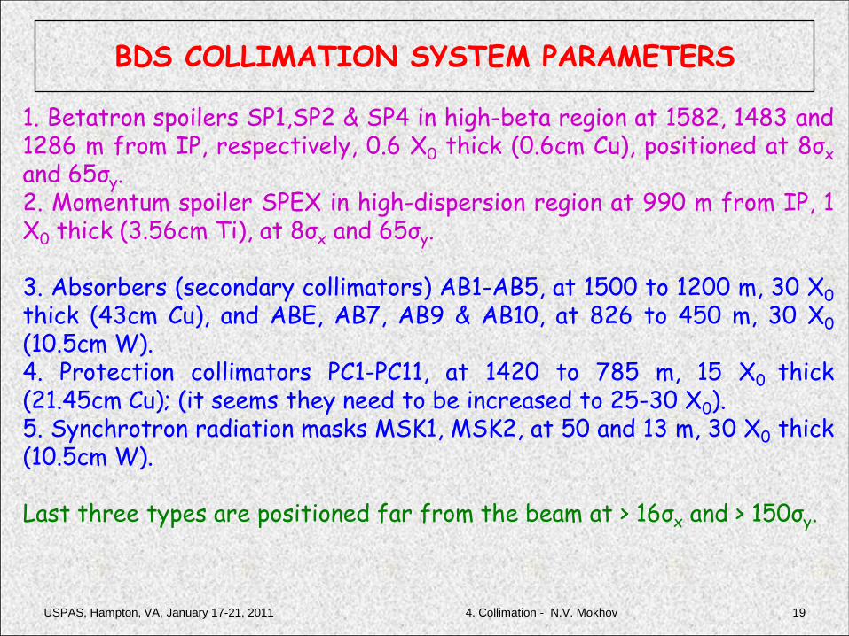
BDS COLLIMATION SYSTEM PARAMETERS
1. Betatron spoilers SP1,SP2 & SP4 in high-beta region at 1582, 1483 and1286 m from IP, respectively, 0.6 X0 thick (0.6cm Cu), positioned at 8σx
and 65σy.2. Momentum spoiler SPEX in high-dispersion region at 990 m from IP, 1X0 thick (3.56cm Ti), at 8σx and 65σy.
3. Absorbers (secondary collimators) AB1-AB5, at 1500 to 1200 m, 30 X0
thick (43cm Cu), and ABE, AB7, AB9 & AB10, at 826 to 450 m, 30 X0
(10.5cm W).4. Protection collimators PC1-PC11, at 1420 to 785 m, 15 X0 thick(21.45cm Cu); (it seems they need to be increased to 25-30 X0).5. Synchrotron radiation masks MSK1, MSK2, at 50 and 13 m, 30 X0 thick(10.5cm W).
Last three types are positioned far from the beam at > 16σx and > 150σy.

USPAS, Hampton, VA, January 17-21, 2011 4. Collimation - N.V. Mokhov 20
COLLIMATION EFFICIENCY AND BEAM LOSS
IP
Collimation efficiency defined hereas a fractional loss of halo chargedparticles, integrated back startingthe IP and normalized to the nominalbunch charge
USPAS, Hampton, VA, January 17-21, 2011 4. Collimation - N.V. Mokhov 21
Collimator Material Damage
•All the possible heat deposition sources guide to instant temperature rise which can be solved by integration of the specific heat equation. •Heat transfer equation can be solved separately then to get real time dependant temperature distribution between bunches. •For metals we need to use all the parameters with real dependency of temperature. •The results of analytical models need to be compared with simulations. ANSYS simulation can be really useful here as it can include phase transformations or melting and possible cracks of material.

USPAS, Hampton, VA, January 17-21, 2011 4. Collimation - N.V. Mokhov22
Thin Spoiler Material Damage
•Ionization (approximations used for analytical study)
•Main source of heating – ionization with possible correction factor due
to electromagnetic shower (1.4 - 2.5)
•Additional information needed for thick structures but not critical for
L<1X0 one can apply 2D models
•One can assume instant temperature rise due to a short bunch length
in comparison with the heat diffusion
•Then one can get the temperature rise per bunch by integration
==
T
x
x
d
bA
v
T
T
vb
d
e
exdx
T
A
kNTcdTTc
dz
dEN
/
0
2
42
)1(
9)()(
0
r

USPAS, Hampton, VA, January 17-21, 2011 4. Collimation - N.V. Mokhov 23
Heat transfer should be solved using
Temperature rise limits:
• Temperature should be far enough from melting
• Induced thermal stress should be far enough from leading to cracksand damage. The stress limit is based on tensile strength, modulus ofelasticity and coefficient of thermal expansion. Sudden T rise createlocal stresses. When DT exceeds stress limit, micro-fractures candevelop.
Thin Spoiler Material Damage: heat transfer and limits
t
T
K
c
y
T
x
TT
e
kTK
b
=
=
rs
p2
2
2
222
2)(
meltutsTT
TE
2
as
Use as an upper limit min{Tmelt, Tstrees} (see next page).

USPAS, Hampton, VA, January 17-21, 2011 4. Collimation - N.V. Mokhov 24
Thin Spoiler Damage: simple example
Simple case: thin, no EMS buildup, specific heat is const
T = 1/(psxsy) × (dE/dx)/Cp × 1.6×10-13 × 2×1010 × Nb
USPAS, Hampton, VA, January 17-21, 2011 4. Collimation - N.V. Mokhov 25
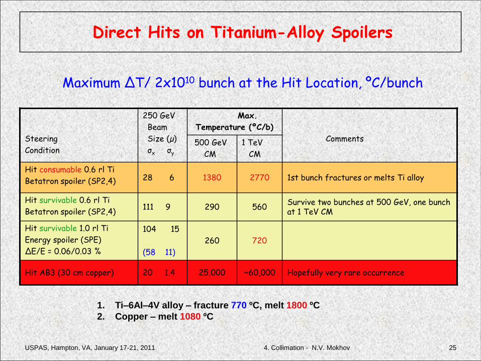
Maximum ΔT/ 2x10¹⁰ bunch at the Hit Location, ºC/bunch
Steering
Condition
250 GeV
Beam
Size (µ)
σx σy
Max.
Temperature (ºC/b)
Comments500 GeV
CM
1 TeV
CM
Hit consumable 0.6 rl Ti
Betatron spoiler (SP2,4) 28 6 1380 2770 1st bunch fractures or melts Ti alloy
Hit survivable 0.6 rl Ti
Betatron spoiler (SP2,4)111 9 290 560
Survive two bunches at 500 GeV, one bunch at 1 TeV CM
Hit survivable 1.0 rl Ti
Energy spoiler (SPE)
∆E/E = 0.06/0.03 %
104 15
(58 11)
260 720
Hit AB3 (30 cm copper) 20 1.4 25,000 ~60,000 Hopefully very rare occurrence
1. Ti–6Al–4V alloy – fracture 770 ºC, melt 1800 ºC
2. Copper – melt 1080 ºC
Direct Hits on Titanium-Alloy Spoilers

USPAS, Hampton, VA, January 17-21, 2011 4. Collimation - N.V. Mokhov 26
Survivable and Consumable Spoilers
A critical parameter is number of bunches #N that MPS will let through to the spoiler before sending the rest of the train to emergency extraction
If it is practical to increase the beam size at spoilers so that spoilers survive #N bunches, then they are survivable
Otherwise, spoilers must be consumable or renewable

USPAS, Hampton, VA, January 17-21, 2011 4. Collimation - N.V. Mokhov 27
Renewable Spoilers
This design was essential for NLC.This concept is now being applied to LHC collimation.

USPAS, Hampton, VA, January 17-21, 2011
Specifics: Hadron Colliders
284. Collimation - N.V. Mokhov
LHC

USPAS, Hampton, VA, January 17-21, 2011 4. Collimation - N.V. Mokhov 29
COLLIMATION AT LHC: 0.5 MW to 5 TW
Collimators are the LHC defense against unavoidable losses:
Irregular fast losses and failures: Passive protection.
Slow losses: Cleaning and absorption of losses in super-conducting environment.
Radiation: Managed by collimators.
Particle physics background: Minimized.
Specified 7 TeV peak beam losses (maximum allowed loss):
Slow: 0.1% of beam per s for 10 s 0.5 MW
Transient: 5 × 10⁻⁵ of beam in ~10 turns (~1 ms) 20 MW
Accidental: up to 1 MJ in 200 ns into 0.2 mm2 5 TW

USPAS, Hampton, VA, January 17-21, 2011 4. Collimation - N.V. Mokhov 30
LHC Phase I Collimator
360 MJ proton beam
1.2 m
3 mm beam passage with RF contacts for
guiding image currents
Designed for maximum robustness:
Advanced CC jaws with water cooling!
Other types: Mostly with different jaw
materials. Some very different with 2
beams!

LHC Tunnel: Primary Betatron Collimators
USPAS, Hampton, VA, January 17-21, 2011 4. Collimation - N.V. Mokhov 31

USPAS, Hampton, VA, January 17-21, 2011 4. Collimation - N.V. Mokhov 32
LHC Collimation Performance: First Run at 1.18 TeV
Tevatron: e ~ 99.9%LHC: e > 99.9%

LHC: Measured Cleaning at 3.5 TeV
factor 1,000
factor 4,000
Betatron Cleaning
IR8factor 600,000
Cleaning efficiency: > 99.975%
USPAS, Hampton, VA, January 17-21, 2011 334. Collimation - N.V. Mokhov
Beam1, vertical beam loss, intermediate settings

USPAS, Hampton, VA, January 17-21, 2011 4. Collimation - N.V. Mokhov 34
PHASE II ADVANCED SECONDARY COLLIMATORS
Replace CCF secondary collimators with shorter ones (lowelectrical resistivity, good absorption, flatness, cooling,radiation): copper-based, ceramics or advanced composites.
Reduction in impedance.
Non-invasive and fast collimator setup with BPM buttonsin jaw.
Improvement of lifetime for warm magnets and remainingPhase I collimators in cleaning insertions.
Rotatable collimators for handling damages in-situ.
Supported construction of TT60 beam test areaHiRadMat. 2 MJ pulsed beam at ~450 GeV from SPS foraccident scenario tests.

USPAS, Hampton, VA, January 17-21, 2011 4. Collimation - N.V. Mokhov 35
INTEGRATED BPM BUTTONS
Integration of BPMs into the jaw assembly gives a clear
advantage for set-up time Prototyping started at CERN
BPM pick-ups
BPM cables and
electrical
connections
R. Assmann, CERN

USPAS, Hampton, VA, January 17-21, 2011 4. Collimation - N.V. Mokhov 36
CRYO COLLIMATORS IN DSC
oll
ima
tor
Warm cleaning insertion
(straight line)
SC bend dipole
(acts as spectrometer)
SC quad
Off-momentum particles
generated by particle-
matter interaction in
collimators (SD scattering)
Ideal orbit (on
momentum)
Add cryogenic collimator, using
space left by missing dipole
(moving magnets)
+ metallic phase 2 collimators in IR3 and IR7
R. Assmann, CERN
Cleaning efficiency improvement by a factor of 15 to 90

USPAS, Hampton, VA, January 17-21, 2011 4. Collimation - N.V. Mokhov 37
-3 m shifted in s
halo
halo
Halo Loss Map
Upgrade Scenario
+3 m shifted in s
Downstream of IR7 b-cleaning
transversely shifted by 3 cm
cryo-collimators
NEW concept
Losses of off-momentum protons from
single-diffractive scattering in TCP
without new magnets
and civil engineering

USPAS, Hampton, VA, January 17-21, 2011 4. Collimation - N.V. Mokhov 38
beambeam
• beam spacing: geometrical constraint
• Length available 1.47 m flange - flange
• Jaw translation mechanism and
collimator support base: LHC Phase I
• >10 kW per jaw Steady State heat
dissipation (material dependent)
Cu coolant supply
tubes twist to
allow jaw rotation
Hub area
Glidcop Cu Mo
Cantilever Mo shaft
@ both ends
Helical cooling channels
25mm below surface
20 facets
ROTATABLE COLLIMATORS (SLAC)

USPAS, Hampton, VA, January 17-21, 2011
Specifics: Muon Colliders
394. Collimation - N.V. Mokhov
m+m-

USPAS, Hampton, VA, January 17-21, 2011 4. Collimation - N.V. Mokhov40
Muon Beam HaloIt was shown that detector backgrounds originating from beam halo canexceed those from decays in the vicinity of IP. Only with a dedicatedbeam cleaning system far enough from IP can one mitigate this problem.
Muons injected with largemomentum errors or betatronoscillations will be lost within thefirst few turns. After that, withactive scraping, the beam halogenerated through beam-gasscattering, resonances and beam-beam interactions at the IP reachesequilibrium and beam losses remainconstant throughout the rest of thecycle. Particle fluxes in detector for 2-TeV
beam halo loss (1% per store) at 200mfrom IP
Endcap Calor.
Tracker
USPAS, Hampton, VA, January 17-21, 2011 4. Collimation - N.V. Mokhov41
DEALING WITH MUON BEAM HALO
• For TeV domain, extraction of beam halo withelectrostatic deflector reduces loss rate in IR bythree orders of magnitude; efficiency of anabsorber-based system is much-much lower.
• For 50-GeV muon beam, a five meter long steelabsorber does an excellent job, eliminating halo-induced backgrounds in detectors.

USPAS, Hampton, VA, January 17-21, 2011
Muon Beam Halo Extraction
424. Collimation - N.V. Mokhov
83% of halo is extractedover the first few turns,with ~8e8 m’s lost in IR,less (but not much) thanlosses over store frommuon beam decays.

USPAS, Hampton, VA, January 17-21, 2011
Muon Beam Halo Scraping
434. Collimation - N.V. Mokhov
At 50-100 GeV, shaving muon halo with a 5-m long steel absorber ina simple compact straight section does an excellent job. Muons looseon average ~10% of their energy and get broad angular and spatialspreads. Therefore, almost all of them are lost in the first 50 mdownstream, providing efficiency w.r.t. IR of > 99.9% and manageabledynamic heat load on lattice elements.

USPAS, Hampton, VA, January 17-21, 2011 4. Collimation - N.V. Mokhov 44
NOVEL COLLIMATION TECHNIQUES
1. Crystal collimation: coherent deflection via channeling and multiple volume reflection of halo particles deep into a secondary collimator. Encouraging results at Tevatron and SPS
4. Hollow electron beam scraper
2. e+,e- beam halo shaving via volume reflection radiation
3. Tail folding technique
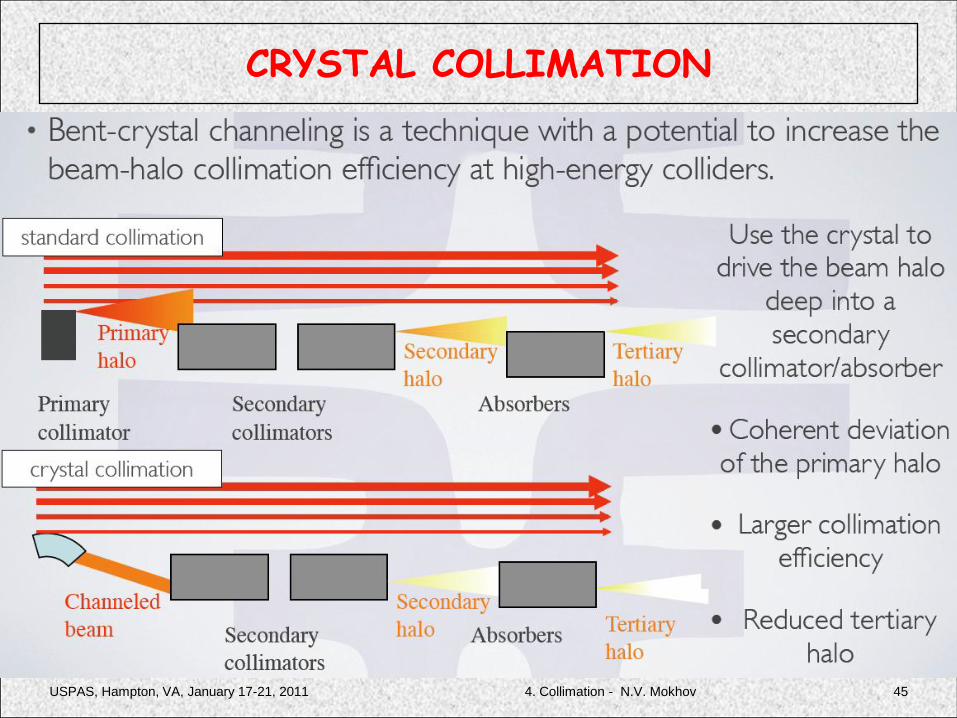
USPAS, Hampton, VA, January 17-21, 2011 4. Collimation - N.V. Mokhov 45
CRYSTAL COLLIMATION
USPAS, Hampton, VA, January 17-21, 2011 4. Collimation - N.V. Mokhov 46
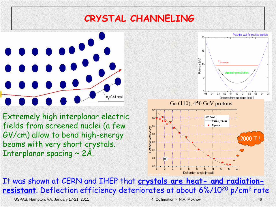
CRYSTAL CHANNELING
It was shown at CERN and IHEP that crystals are heat- and radiation-resistant. Deflection efficiency deteriorates at about 6%/1020 p/cm2 rate
Extremely high interplanar electricfields from screened nuclei (a few GV/cm) allow to bend high-energy beams with very short crystals. Interplanar spacing ~ 2Å.
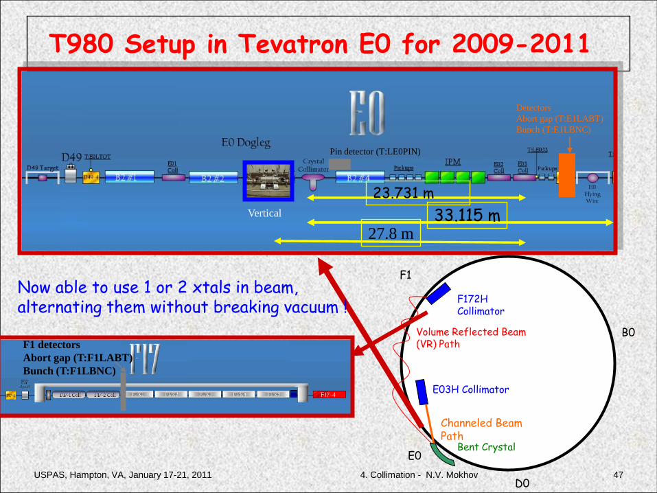
T980 Setup in Tevatron E0 for 2009-2011
Bent Crystal
E03H Collimator
Channeled Beam Path
Volume Reflected Beam (VR) Path
F172H Collimator
B0
E0
F1
D0
Vertical 33.115 m
23.731 m
27.8 m
F1 detectors
Abort gap (T:F1LABT)
Bunch (T:F1LBNC)
Pin detector (T:LE0PIN)
Detectors
Abort gap (T:E1LABT)
Bunch (T:E1LBNC)
Now able to use 1 or 2 xtals in beam,alternating them without breaking vacuum !
USPAS, Hampton, VA, January 17-21, 2011 474. Collimation - N.V. Mokhov
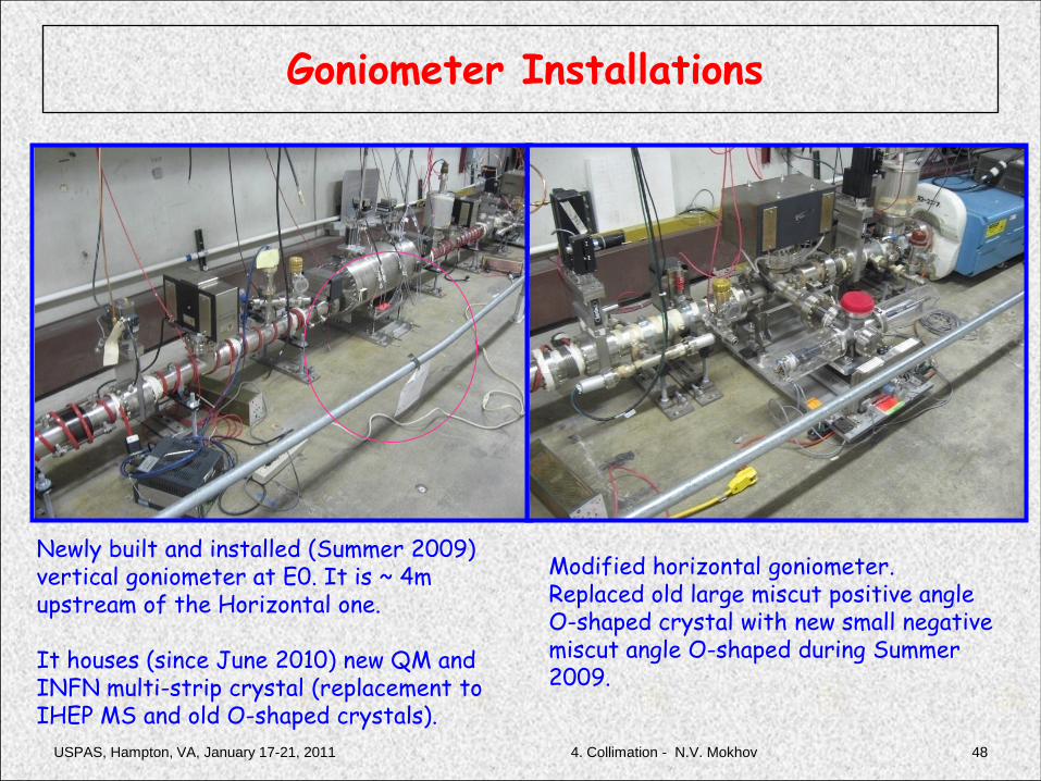
Goniometer Installations
Newly built and installed (Summer 2009) vertical goniometer at E0. It is ~ 4m upstream of the Horizontal one.
It houses (since June 2010) new QM and INFN multi-strip crystal (replacement toIHEP MS and old O-shaped crystals).
Modified horizontal goniometer. Replaced old large miscut positive angle O-shaped crystal with new small negative miscut angle O-shaped during Summer 2009.
USPAS, Hampton, VA, January 17-21, 2011 484. Collimation - N.V. Mokhov

USPAS, Hampton, VA, January 17-21, 2011 4. Collimation - N.V. Mokhov 49
980-GEV BEAM CHANNELING: DATA vs THEORY
Oct. 6, 2005By Dean Still
Jan. 31, 2006
With E03H out,LE033C BLM isproportional tonuclear interact.rate in crystal
Channeled beam“peak” width is22±4 mrad (rms)
USPAS, Hampton, VA, January 17-21, 2011 4. Collimation - N.V. Mokhov 50
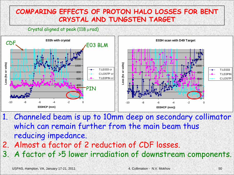
COMPARING EFFECTS OF PROTON HALO LOSSES FOR BENT CRYSTAL AND TUNGSTEN TARGET
E03h with crystal
0
200
400
600
800
1000
1200
1400
-10 -8 -6 -4 -2 0
E03HCP (mm)
Lo
ss (
hz o
r vo
lts)
T:LE033 cr
C:LOSTP cr
T:LE0PIN cr
E03H scan with D49 Target
0
200
400
600
800
1000
1200
1400
-10 -8 -6 -4 -2 0
E03HCP (mm))
Lo
ss (
hz o
r vo
lts)
T:LE033
T:LE0PIN
C:LOSTP
1. Channeled beam is up to 10mm deep on secondary collimator which can remain further from the main beam thus reducing impedance.
2. Almost a factor of 2 reduction of CDF losses. 3. A factor of >5 lower irradiation of downstream components.
Crystal aligned at peak (118 mrad)
E03 BLMCDF
PIN

USPAS, Hampton, VA, January 17-21, 2011 4. Collimation - N.V. Mokhov 51
VOLUME REFLECTION
Predicted by Taratin&Vorobiev in 1987.Recently demonstrated at IHEP & CERN
Promising for collimation: acceptance = bent angle(e.g., 400 mrad, to be compared to ~10 mrad for channeling)

New Ferrara Multi-Strip Crystal
USPAS, Hampton, VA, January 17-21, 2011 524. Collimation - N.V. Mokhov
θVR
θVR
θVR
1. Anticlastic curvature radius = 4.2 m2. Expected acceptance = 80 mrad3. Number of strips aligned/used = 134. Miscut angle was measured as 600 mrad5. Characterized, tested and installed in vertical goniometer6. Produced by V. Guidi, Ferrara, INFN

Pixel Telescope Detectors
USPAS, Hampton, VA, January 17-21, 2011 534. Collimation - N.V. Mokhov
USPAS, Hampton, VA, January 17-21, 2011 4. Collimation - N.V. Mokhov 54
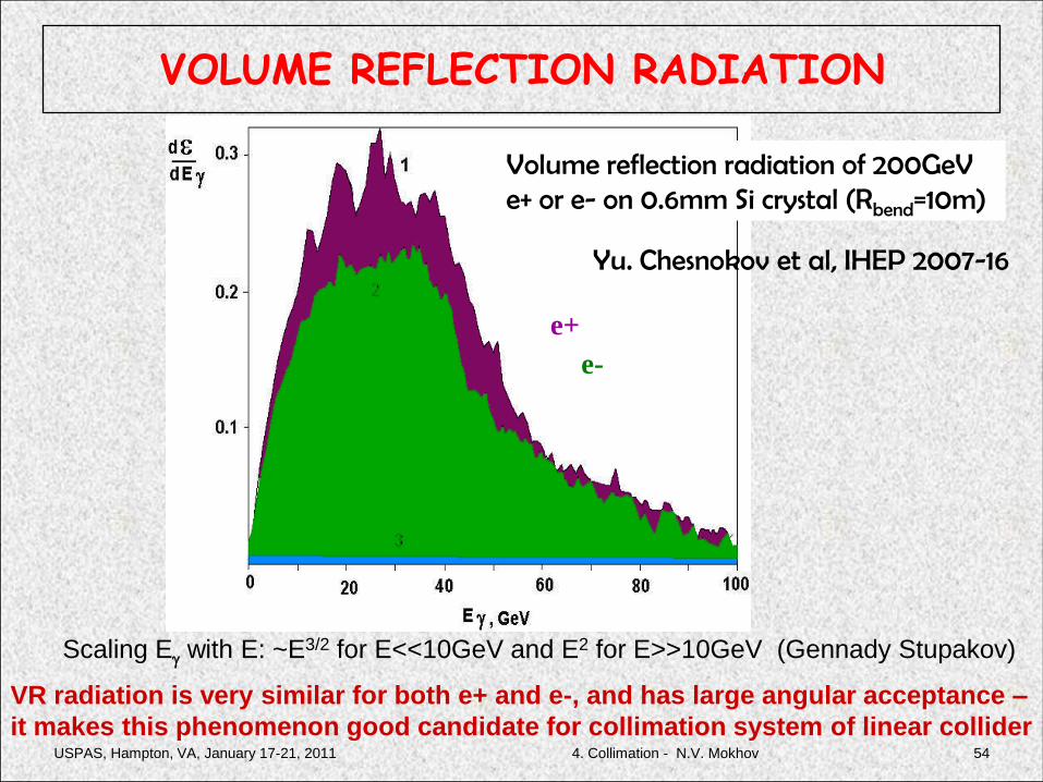
VOLUME REFLECTION RADIATION
Volume reflection radiation of 200GeV e+ or e- on 0.6mm Si crystal (Rbend=10m)
e+
e-
Yu. Chesnokov et al, IHEP 2007-16
Scaling Eg with E: ~E3/2 for E<<10GeV and E2 for E>>10GeV (Gennady Stupakov)
VR radiation is very similar for both e+ and e-, and has large angular acceptance –
it makes this phenomenon good candidate for collimation system of linear collider

USPAS, Hampton, VA, January 17-21, 2011 4. Collimation - N.V. Mokhov 55
Beam
halo
Crystal
with Volume
Reflection
photons of VR
radiation (to be
absorbed in
dedicated places)
Bends
VR halo particles
with dE/E~20%
loss due to VR
radiation
e+ e- Beam Collimation Based on VR radiation
Absorb off E
particles

USPAS, Hampton, VA, January 17-21, 2011 4. Collimation - N.V. Mokhov 56
Nonlinear Handling of Beam Tails
• One wants to focus beam tails but not to change the core of the beam– use nonlinear elements
• Several nonlinear elements need to be combined to provide focusing in all directions– (analogy with strong focusing by
FODO)
• Octupole Doublets (OD) can be used for nonlinear tail folding
Single octupole focus in planes and defocus on diagonals.
An octupole doublet can focus in all directions !
Courtesy A. Seryi
USPAS, Hampton, VA, January 17-21, 2011 4. Collimation - N.V. Mokhov 57
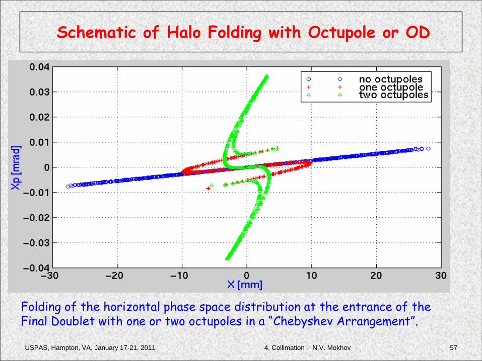
Schematic of Halo Folding with Octupole or OD
Folding of the horizontal phase space distribution at the entrance of the Final Doublet with one or two octupoles in a “Chebyshev Arrangement”.

USPAS, Hampton, VA, January 17-21, 2011 4. Collimation - N.V. Mokhov 58
Predicted Tail Folding Effect
Tail folding by means of two octupole doublets in the new NLC final focus
Input beam has (x,x’,y,y’) = (14mm,1.2mrad,0.63mm,5.2mrad) in IP units
(flat distribution, half width) and 2% energy spread,
that corresponds approximately to Ns=(65,65,230,230) sigmas
with respect to the nominal NLC beam
QF1
QD0QD6
Oct.
Two octupole doublets give tail folding by ~ 4 times in terms of beam size in FD. This can lead to relaxing collimation requirements by ~ a factor of 4.
USPAS, Hampton, VA, January 17-21, 2011 4. Collimation - N.V. Mokhov 59
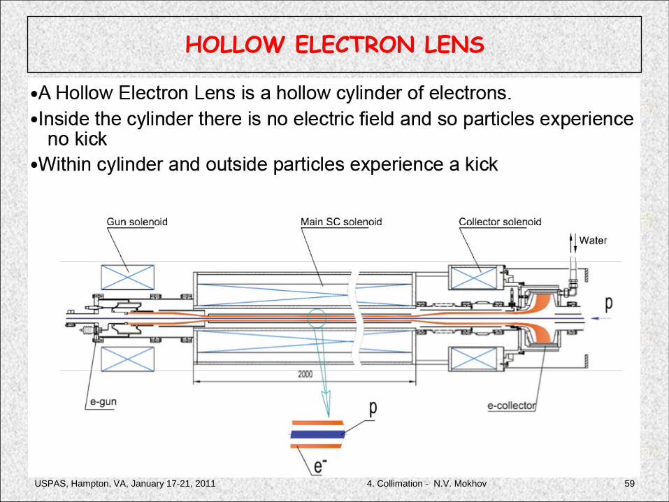
HOLLOW ELECTRON LENS

USPAS, Hampton, VA, January 17-21, 2011 4. Collimation - N.V. Mokhov 60
CONVENTIONAL vs HOLLOW LENS COLLIMATION
Indestructible non-invasiveelectron beam at a smallerradius can push halo out,can be used to eliminateloss spikes due to shakingbeam and can increaseimpact parameter of primaries
No material can survivecloser than 5 s

USPAS, Hampton, VA, January 17-21, 2011 4. Collimation - N.V. Mokhov 61
BUNCH DISTRIBUTION
Basic parameters similar to TEL.R&D required on hollow electrongun.CERN & LARP are supportive.