partial stroke testing for srd991 and srd960 · pdf filepartial stroke testing for srd991 and...
TRANSCRIPT

Technical Information 04.09 TI EVE0105 PST-(en)
Partial Stroke Testing for SRD991 and SRD960
Final control elements in Emergency Shutdown (ESD) applications such as ON-OFF-, Blow Down and Venting-Valves remain in one position over a longer time without any mechanical movement. These valves can show the tendency to get stuck and as a result might not operate upon demand. This can have a severe impact on the functionality of a Safety System and could result in an adverse condition to the operating personnel, plant equipment and the environment. The Partial Stroke Test (PST) offers operators a tool to identify the troubleshooting function of ESD valves. The test can be easily executed via the FDT-DTM based configuration and diagnostic tool VALcare™ and Valve Monitor.
MAIN FEATURES PST Activation:
• Manually on board (LCD + push buttons)
• Automatically • Through a separate Binary Input
for SIS Logic Solver • LCP960 for local monitoring of PST
Configuration: • Test Interval • Setpoint Change • Maximum Wait Time • Minimum Pressure
• Testing Status through communication, LCD and Binary Output
• Predictive Maintenance by means of Break Pressure trend, Re-inflate trend
• PST signature • Complete PST report for print out • PST with Fail Open (full pressure in output) or
with Fail Safe (depressurizing output) • PST for single or double acting Actuator • PST with HART / Profibus PA and FF H1
2 PST for SRD991/SRD960 TI EVE0105 PST-(en)
1 INTRODUCTION TO PARTIAL STROKE TEST: Safety instrumented systems (SISs), commonly known as emergency shutdown (ESD) or safety interlock systems, are required to be tested at a periodic interval based on their design to assure their functionality and to achieve the required safety integrity level (SIL). Traditionally, system testing, if it was done at all, was done during unit shutdowns or turnarounds that occurred annually or, for larger units, perhaps every two to three years. These tests are known as Full Stroke Test. Where turnarounds of one or two years have provided adequate opportunity to test full stroke valve functionality at a rate commensurate with the probability-of-failure-on-demand (PFD) requirements of its design Safety Integrity Level (SIL) provide an opportunity for additional testing. Today’s longer turnarounds are requiring plant operators to seek ways to test functionality without compromising valve safety availability during normal operation. Extended turnarounds in the process industries have posed a challenge to conventional ESD valve proof testing. Partial stroke testing (PST) emerges as a natural on-line proof-testing complement. Partial stroke testing is a method where the SIS valve is typically moved 10-20% and returned to its original position in a short period of time. As the most common dangerous failure mode in a static ESD valve is “stuck”, on-line partial stroke testing made by the intelligent positioner SRD991 (intrinsic safety application) and SRD960 (Explosion proof application) is the key to the safety.
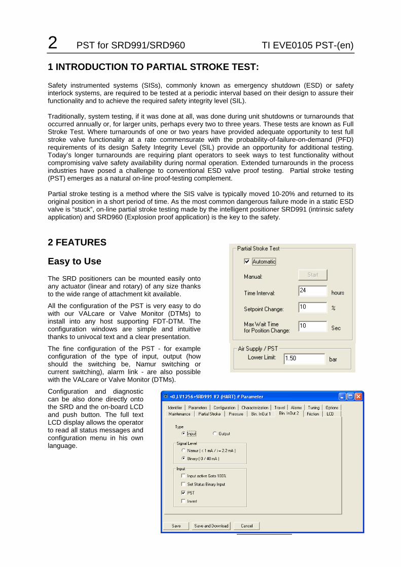
2 FEATURES
Easy to Use
The SRD positioners can be mounted easily onto any actuator (linear and rotary) of any size thanks to the wide range of attachment kit available.
All the configuration of the PST is very easy to do with our VALcare or Valve Monitor (DTMs) to install into any host supporting FDT-DTM. The configuration windows are simple and intuitive thanks to univocal text and a clear presentation.
The fine configuration of the PST - for example configuration of the type of input, output (how should the switching be, Namur switching or current switching), alarm link - are also possible with the VALcare or Valve Monitor (DTMs).
Configuration and diagnostic can be also done directly onto the SRD and the on-board LCD and push button. The full text LCD display allows the operator to read all status messages and configuration menu in his own language.

TI EVE0105 PST-(en) PST for SRD991/SRD960 3
Time Saving
The remote testing capability does not require the presence of a technician on the valve during the PST itself. However, technicians still have the ability to perform a PST thanks a push button in the field.
PST Alert
While performing the partial stroke test, if for any reason the valve is stuck, the positioner will abort the test and send a message to request maintenance. An indication of the problem, will appear on the LCD display of the positioner, and the binary output will switch (information for the Logic Solver for example). Through digital communication, the information will reach a DCS or a PC.
On a PC dedicated to maintenance or on the DCS equipped with VALcare or Valve Monitor (DTMs), the information is visualized under the NAMUR NE107 (recommended for diagnostic presentation).
Moreover this information can be stored and read by a condition monitoring system like Avantis CM (Conditioning Monitoring). The Avantis CM will notify key personnel by email (for example whenever an PST bad status occurs) and recommend a list of corrective actions.
4 PST for SRD991/SRD960 TI EVE0105 PST-(en)
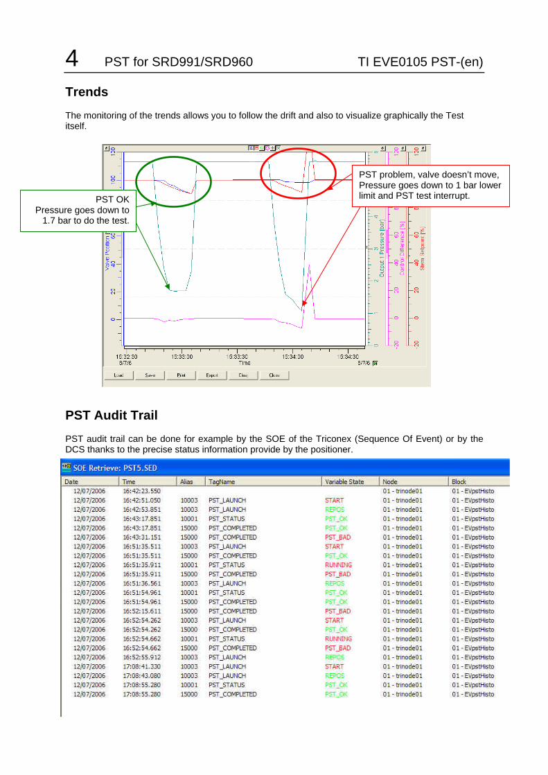
Trends
The monitoring of the trends allows you to follow the drift and also to visualize graphically the Test itself.
PST Audit Trail
PST audit trail can be done for example by the SOE of the Triconex (Sequence Of Event) or by the DCS thanks to the precise status information provide by the positioner.
.
PST OK Pressure goes down to
1.7 bar to do the test.
PST problem, valve doesn’t move, Pressure goes down to 1 bar lower limit and PST test interrupt.

TI EVE0105 PST-(en) PST for SRD991/SRD960 5
Predictive Maintenance
Advanced diagnostic capabilities accessed via digital communication (HART for example) allow predictive maintenance thanks to trend analysis. The easy user interface inside the DTM (VALcare or Valve Monitor) enables the operator to understand immediately if there is a drift in the behaviour. The Monitoring of the Break Pressure (Trend) enable to follow an eventual drift of the friction at valve 100%. The Monitoring of the Re-Inflate Time (Trend) enable to follow the drift of the friction on the PST and also the status of air supply.
Continuous Auto Check
During the test, the positioner checks all control parameters as well as the functionality of all pneumatic and electrical components. Even if the positioner in the normal position doesn’t control the position and provide full output pressure, the positioner continuously checks the proper workings of all electronic parts and electrical connection between electronic, option board, potentiometer and I/P converter. All this enables in connection with the Alarm Link Scheduler the precise configuration of the Alarm that switches the binary output. Pressure Control Active
At any time the positioner monitors the input and output pressure. If the input air supply pressure fall below a certain level, an alarm can be set to indicate that some maintenance should be done on the air supply line. On the output pressure, a minimum pressure is also set in order to interrupt the PST. Like this positioner avoids in case the valve stuck a possible overshoot.
6 PST for SRD991/SRD960 TI EVE0105 PST-(en)
Soft PST
Slow and Accurate, the Soft PST function allows to perform the change of setpoint of the PST with a very low speed. A PST ramp can be configured up to 100 s in order to avoid any chock given by the fast closing or opening. Soft PST function is also an additional safety to protect the valve against any overshoot in case of increasing friction. Of course in case of emergency the valve will close or open at maximum speed!
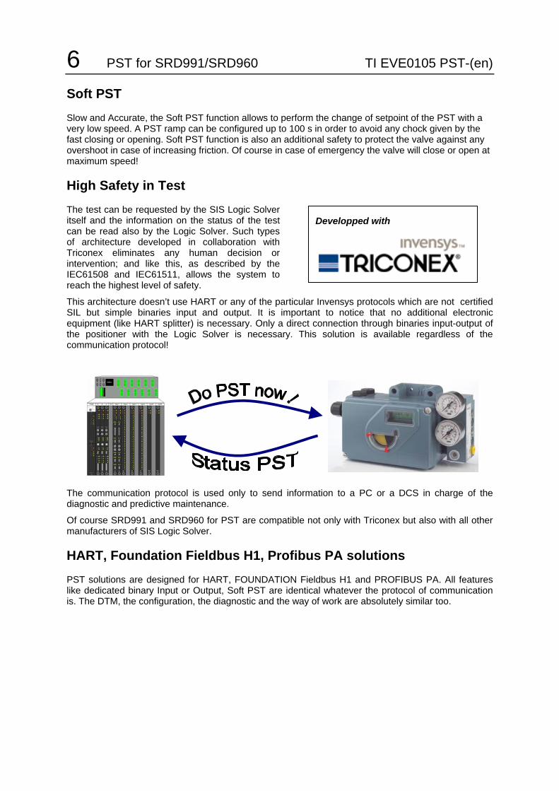
High Safety in Test
The test can be requested by the SIS Logic Solver itself and the information on the status of the test can be read also by the Logic Solver. Such types of architecture developed in collaboration with Triconex eliminates any human decision or intervention; and like this, as described by the IEC61508 and IEC61511, allows the system to reach the highest level of safety.
This architecture doesn’t use HART or any of the particular Invensys protocols which are not certified SIL but simple binaries input and output. It is important to notice that no additional electronic equipment (like HART splitter) is necessary. Only a direct connection through binaries input-output of the positioner with the Logic Solver is necessary. This solution is available regardless of the communication protocol!
The communication protocol is used only to send information to a PC or a DCS in charge of the diagnostic and predictive maintenance.
Of course SRD991 and SRD960 for PST are compatible not only with Triconex but also with all other manufacturers of SIS Logic Solver.
HART, Foundation Fieldbus H1, Profibus PA solutions
PST solutions are designed for HART, FOUNDATION Fieldbus H1 and PROFIBUS PA. All features like dedicated binary Input or Output, Soft PST are identical whatever the protocol of communication is. The DTM, the configuration, the diagnostic and the way of work are absolutely similar too.
Developped with

TI EVE0105 PST-(en) PST for SRD991/SRD960 7
Local Control Panel LCP960
A Local Control Panel certified ATEX II 2 G EEx d can be also used to do a local monitoring of the PST. A push buttons on the LCP activate the PST and the status of the PST can be read inc lear through a backlight LCD.
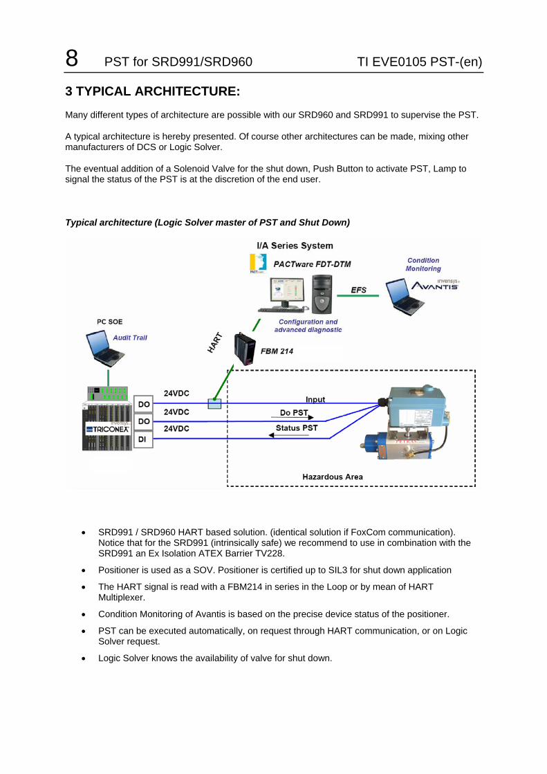
8 PST for SRD991/SRD960 TI EVE0105 PST-(en) 3 TYPICAL ARCHITECTURE:
Many different types of architecture are possible with our SRD960 and SRD991 to supervise the PST.
A typical architecture is hereby presented. Of course other architectures can be made, mixing other manufacturers of DCS or Logic Solver.
The eventual addition of a Solenoid Valve for the shut down, Push Button to activate PST, Lamp to signal the status of the PST is at the discretion of the end user.
Typical architecture (Logic Solver master of PST and Shut Down)
• SRD991 / SRD960 HART based solution. (identical solution if FoxCom communication). Notice that for the SRD991 (intrinsically safe) we recommend to use in combination with the SRD991 an Ex Isolation ATEX Barrier TV228.
• Positioner is used as a SOV. Positioner is certified up to SIL3 for shut down application
• The HART signal is read with a FBM214 in series in the Loop or by mean of HART Multiplexer.
• Condition Monitoring of Avantis is based on the precise device status of the positioner.
• PST can be executed automatically, on request through HART communication, or on Logic Solver request.
• Logic Solver knows the availability of valve for shut down.
TI EVE0105 PST-(en) PST for SRD991/SRD960 9
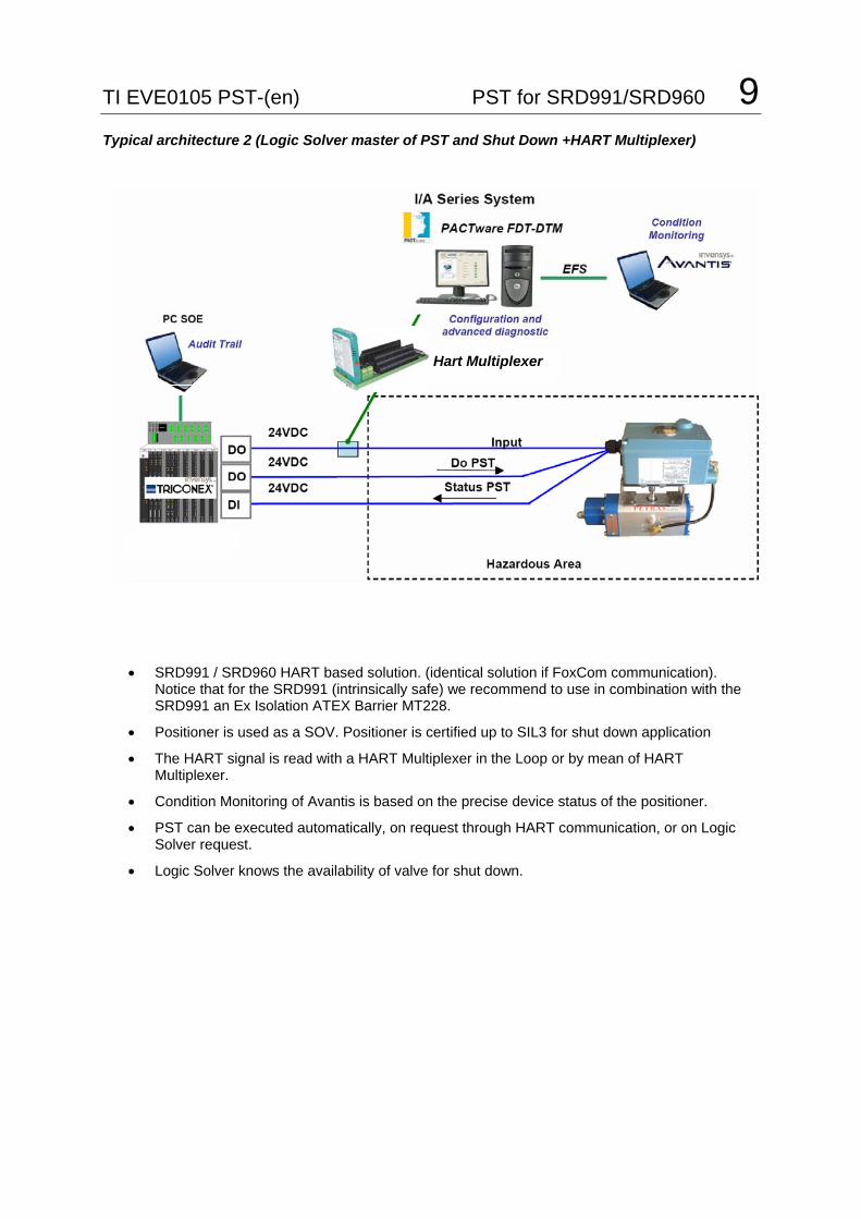
Typical architecture 2 (Logic Solver master of PST and Shut Down +HART Multiplexer)
• SRD991 / SRD960 HART based solution. (identical solution if FoxCom communication). Notice that for the SRD991 (intrinsically safe) we recommend to use in combination with the SRD991 an Ex Isolation ATEX Barrier MT228.
• Positioner is used as a SOV. Positioner is certified up to SIL3 for shut down application
• The HART signal is read with a HART Multiplexer in the Loop or by mean of HART Multiplexer.
• Condition Monitoring of Avantis is based on the precise device status of the positioner.
• PST can be executed automatically, on request through HART communication, or on Logic Solver request.
• Logic Solver knows the availability of valve for shut down.
Hart Multiplexer

10 PST for SRD991/SRD960 TI EVE0105 PST-(en)
Typical architecture 3 (LCP960 and SRD960 +HART Multiplexer) Use of the Local Control Panel LCP960 in combination to SRD960
• SRD960 HART based solution. (identical solution if FoxCom communication).
• Positioner is used as a SOV. Positioner is certified up to SIL3 for shut down application
• The HART signal is read with a HART Multiplexer in the Loop or by mean of HART Multiplexer.
• Condition Monitoring of Avantis is based on the precise device status of the positioner.
• PST can be executed automatically, on request through HART communication, or on LCP960 request.
• LCP960 give the feedback of the PST Status as well as the timer (when was done last PST)
• LCP960 can be use with any SRD960 independently of the protocol of communication.
• Fully ATEX Ex d certified solution
TI EVE0105 PST-(en) PST for SRD991/SRD960 11
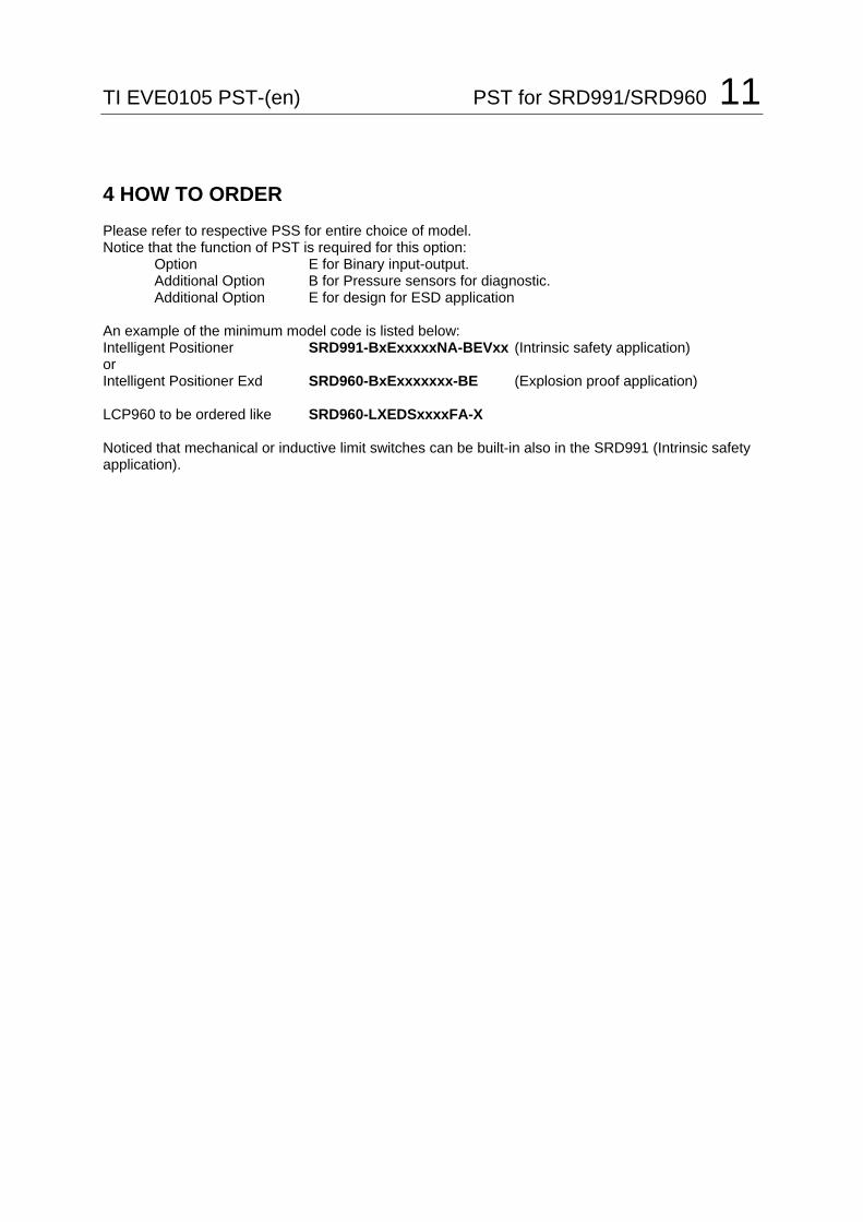
4 HOW TO ORDER Please refer to respective PSS for entire choice of model. Notice that the function of PST is required for this option: Option E for Binary input-output. Additional Option B for Pressure sensors for diagnostic. Additional Option E for design for ESD application An example of the minimum model code is listed below: Intelligent Positioner SRD991-BxExxxxxNA-BEVxx (Intrinsic safety application) or Intelligent Positioner Exd SRD960-BxExxxxxxx-BE (Explosion proof application) LCP960 to be ordered like SRD960-LXEDSxxxxFA-X Noticed that mechanical or inductive limit switches can be built-in also in the SRD991 (Intrinsic safety application).

12 PST for SRD991/SRD960 TI EVE0105 PST-(en) 5 SPECIFICATIONS OF PARTIAL STROKE TEST PST made with intelligent positioners SRD991 for Intrinsically Safe application or SRD960 for Explosion Proof application with specific functionality of PST.
Supply 24VDC or 4-20mA. Communication protocols HART, PROFIBUS PA, FOUNDATION Fieldbus H1. Additional binary inputs and outputs for request PST from SIS logic solver and feedback status.
FDT-DTM software for configuration and advanced diagnostics
Activation of Test: • Manually (locally on built-in push button with LCD display or through communication) • Automatically • Through a separate binary input for SIS logic solver • LCP960 (Local Control Panel)
Testing Status (status read through communication) • Not Done • Running • Restricted • OK
Status PST available through digital outputs for SIS logic solver or external signalisation
Configuration: • Test Interval [Hours] • Setpoint Change [%] Limited at maximum 30%.
High Safety of the PST • Maximum Wait Time [Seconds] • Minimum Pressure [bar] Minimum pressure between 0 to 6 bars • Soft PST [Seconds] Ramp freely configurable up to 100 s.
SIL (Safety Integrity Level) SRD991 and SRD960 are suitable for use in a safety related application up to SIL 3 according to IEC 61511-1. Certificate released by Exida.
Request of PST from SIS logic solver and feedback are totally independent from the protocol of communication.
Environment Integration: • Full integration into IA Series System (FBM214 for HART communication) and Avantis CM. • Full integration into any other DCS that support FDT-DTM standard. • Full integration with Triconex SIS logic solver (Tricon and Trident). • Full integration with any other SIS logic solver. • Full integration with any HART multiplexer and DCS or stand alone PC network.
SRD991 and SRD960 can be mounted easily onto any ESD (Emergency Shut Down) or ESV (Emergency Shut Vent) valves. A wide range of mounting kits is available for that.
LCD Display on SRD991 and SRD960 with full text in many different languages and push buttons for an easy configuration and diagnostic on board.
Rugged aluminium casing with show window for LCD display.
Additional built-in inductive or mechanical limit switches for SRD991.
Predictive Maintenance : Break Pressure Trend / Re-Inflate Time Trend / PST Signature
Complete PST report with all diagnostics for print out (by means of FDT-DTM).
PST for single and double acting
Fail Open (Full pressure in Output in case of Fail) or Fail Safe (Depressurized Output in case of Fail)

TI EVE0105 PST-(en) PST for SRD991/SRD960 13
Additional Documentation for these products: Technical Information for Attachment Kits for Positioners TI EVE0011 A Overview of Attachment Kits of all positioners on actuators/valves of different
manufacturers Technical Information for commissioning of PST positioners TI EVE0205 PST How to set up the Partial Stroke Testing for SRD991 and SRD960 SRD991 Quick Guide: QG EVE0105 A/B Extract of Master Instruction for an easy to use, understand, and fast
start-up guide. This document highlights the most important benefits. Product Specification Sheet: PSS EVE0105 E SRD991 -all versions- Master Instructions: MI EVE0105 E SRD991 -all versions-
SRD960 Quick Guide: QG EVE0109 A Extract of Master Instruction for an easy to use, understand and fast
start-up guide. This document highlights the most important benefits. Product Specification Sheet: PSS EVE0109 A SRD960 -all versions- Master Instructions: MI EVE0109 A SRD960 -all versions-
SRD991 and SRD960 Technical Information for Fieldbus-Communication: TI EVE0105 P SRD991/960 -PROFIBUS-PA TI EVE0105 Q SRD991/960 -FOUNDATION Fieldbus H1
Instruction for HART-Communication: MI EVE0105 B HART with Hand-Held Terminal
FOXBORO ECKARDT GmbH ECKARDT S.A.S. Pragstrasse 82 20 rue de la Marne D-70376 Stuttgart F-68360 Soultz Germany France Tel. + 49(0)711 502-0 Tel. + 33 (0)3 89 62 15 30 Fax + 49(0)711 502-597 Fax + 33 (0)3 89 62 14 85
http://www.foxboro-eckardt.com DOKT http://www.foxboro-eckardt.de http://www.foxboro.com/instrumentation/