partial discharge measuring systems - presco ag · pdf filethe partial discharge detector...
TRANSCRIPT

Presco AGZürcherstrasse 70 -CH 8104 Weiningen Tel. + 41 44 750 63 63 Fax + 41 44 750 63 66P.O. Box 155 Switzerland Email : [email protected]
Internet : www.prescoag.com
PD_Marketing.doc page 1 of 17
Partial Discharge Measuring SystemsDescription –Technical Data –Features –Accessories - Options
www.prescoag.com

Presco AG
PD_Marketing.doc page 2 of 17
1. General Features
Suitable for any kind of test object
Diagnosis of high voltage insulations according IEC 60270
Real analogue processing–no hiding
Selectable broadband filters
Tuneable narrow band filter
Interference gating; 6 individually adjustable windows
Combined analogue and/or digital display
Direct measurement of HV
Oscilloscope outputs for direct observation of PD activities
Auto and manual calibration
Auto and manual ranging
Remote control and data transfer trough built in RS 232 interface
Phase Resolved Pattern / Finger Print (type PD-4)
Complete system incl. detector, Calibrator, Coupling Device and cable
Different options
Incl. Test Certificate granting full traceability to international standards

Presco AG
PD_Marketing.doc page 3 of 17
2. Theory
The instrument detects and quantifies partial discharges (PD) in a high voltage test object.The detection technology fulfils the current and forthcoming international standard IEC270 [1]or IEC 60270 [2].
Fig. 1 shows the principle of the measurement.
In the insulation of the test object (Ct), under high voltage stress, localised electricaldischarges can be generated. These discharges, which appear in general as individualevents of very short duration, are called partial discharges. They do not immediately resultin breakdown of the insulation but with time they can slowly damage the insulation andfinally lead to a breakdown. The partial discharges generate short duration current pulsesat the terminals of the test object and in the PD test circuit. A so called „coupling capacitor“ (Ck) is connected parallel to the test object. Through Ck also the PD currentpulses will flow. The integral of the individual current pulses is the so called „apparent charge“ of a PD event. According to IEC 60270, the capacitance of Ck shall be higher thanthe capacitance of the test object (Ct). The apparent charge is the basic quantity of thepartial discharges in the test object. From this quantity, many other quantities related toPD pulses can be derived, as e.g. the „average discharge current I“ or „discharge power P“ (see [2]).

Presco AG
PD_Marketing.doc page 4 of 17
The coupling device has the purpose to separate the PD current pulses from the powerfrequency test voltage circuit. The coupling device, used in the measuring system, hasmore purposes:
- At on higher frequencies (20 kHz ... 2 MHz) it shows an input impedance of200or.
- For test-voltage frequencies (45 Hz .. 450 Hz) it works as a voltage divider. The divider-capacitance is called Cdiv and it has normally a value of 1 F.
Therefore, this device separates first the low frequency voltage and the high frequencycurrent, then transforms the partial-discharge proportional current to voltage and mixes thelow frequency and high frequency voltages in a cable with 50 impedance characteristic.The partial discharge detector „separates“ the low and high frequency voltages. The voltage proportional to the partial discharge current pulses will be amplified and a low-pass filter makes the so called „quasi-integration“ [3]. The peak value of the output impulse-voltage of the filter is proportional to the charge delivered by an individual PDcurrent pulse.A peak-detector generates a voltage proportional to the repetitive peak values and thissignal is then digitally filtered and displayed on a LED display. The displayed value isproportional to the „largest repeatedly - occurring PD-magnitude“ of the apparent charge q as specified within the standards, as the peak-detector fulfils the pulse-train response ofthe newest standard IEC 60270.The low frequency path of the detector processes the high voltage on the test object. Theseparated low frequency voltage is fed to an A/D converter, located in the microcontrollerof the detector and it will be there sampled and processed. The processed value is sent toa LCD screen.
Presco AG
PD_Marketing.doc page 5 of 17
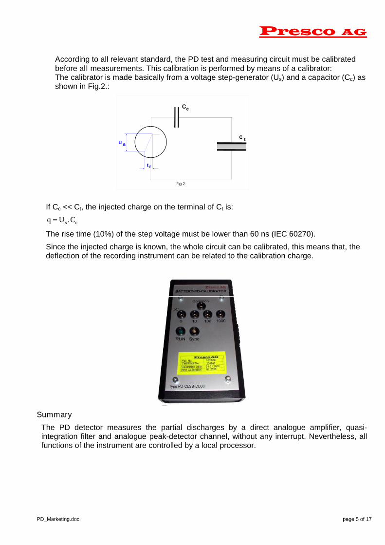
According to all relevant standard, the PD test and measuring circuit must be calibratedbefore all measurements. This calibration is performed by means of a calibrator:The calibrator is made basically from a voltage step-generator (Us) and a capacitor (Cc) asshown in Fig.2.:
If Cc << Ct, the injected charge on the terminal of Ct is:
q U Cs c .
The rise time (10%) of the step voltage must be lower than 60 ns (IEC 60270).
Since the injected charge is known, the whole circuit can be calibrated, this means that, thedeflection of the recording instrument can be related to the calibration charge.
Summary
The PD detector measures the partial discharges by a direct analogue amplifier, quasi-integration filter and analogue peak-detector channel, without any interrupt. Nevertheless, allfunctions of the instrument are controlled by a local processor.
Presco AG
PD_Marketing.doc page 6 of 17
3. Technical Specifications
3.1 Professional Partial Discharge Measuring System Type PD-4
Detector
supplied with calibration certificatePD ranges 10 - 100 - 1000 - 10’000 - 100’000 pCPD input impedance 50 PD readout LCD graphics digital, analogue or phaseresolved patternPD uncertainty ± 3% of rangePD output ± 1V, 50 High pass of broadband filter selectable 20 kHz or 100 kHz / 6 dBLow pass of broadband filter selectable 200 kHz or 400 kHz / 6 dBMiddle frequency of narrow band filter selectable 60... 250 kHzBandwidth of narrow band filter 9 KHzGating up to 6 individual adjustable gates (hardware
gating)Auto calibration 10 pC–10 000 pCAuto ranging PD and voltage measurementOscilloscope output Voltage proportional sine and PD proportional
signalVoltage measurement 100 V... 1 MVFrequency range of voltage measurement 45 ... 150 HzVoltage scale factor 1 ... 10' 000Uncertainty of voltage measurement 1 % of readingDisplay analogue, digital, PD activities as y(t) plot as
lines or dots, persistent or cumulated, PDpattern
Interface RS232 (for data transfer and remote control)Dimensions 455 130 350 (w h d in mm) (19")Weight approx. 6 kg, 20 lb.Power mains 230/115 V / 50/60 Hz / 25 VA (other voltageson request)
Coupling devicePD and AC signal are mixed in a single 50 coax cable
input impedance of PD-channel 200 (or 500 for cable measurementsAC channel input impedance 1 MBandwidth of PD-channel 20 kHz ... 2 MHz / 6 dBBandwidth of AC-channel 45 Hz ... 450 HzMax. AC input voltage 100 Vpeak/2AC divider capacitance standard 1 F (optional up to 40 F)Output impedance 50 / 20 kHz ... 2 MHz

Presco AG
PD_Marketing.doc page 7 of 17
Specifications PD-4 cont.
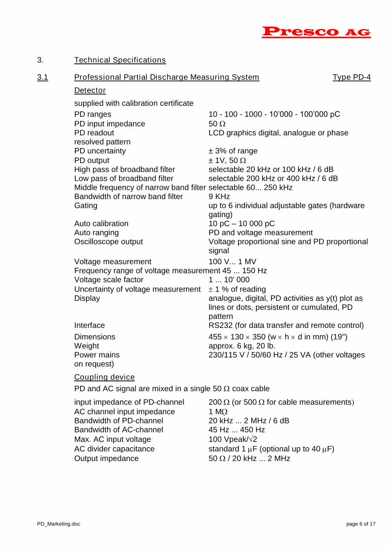
Battery Calibrator
Supplied with calibration certificate
Charge values 5 - 10 - 100 - 1000 pCOutput capacitance < 150 pFRise time < 60 nsPower supply 9 V battery type 6LR61Battery life > 20 hours of continuous operationSynchronisation optical pick-up of power frequency from
nearby lampsUncertainty ± 3%
Measuring Cable
Coaxial 50 / 20 m BNC- BNC
Type PD-4 Partial Discharge Detector
Presco AG
PD_Marketing.doc page 8 of 17
3.2 Industry Partial Discharge Measuring System Type PD-5
Detectorsupplied with calibration certificatePD ranges 10 - 100 - 1000 - 10’000 - 100’000 pCPD input impedance 50 PD readout LCD graphics analoguePD uncertainty ± 3% of rangePD output ± 1V, 50 High pass of broadband filter selectable 20 kHz or 100 kHz / 6 dBLow pass of broadband filter selectable 200 kHz or 400 kHz / 6 dBAuto calibration 10 pC–10 000 pCAuto ranging PD and voltage measurementOscilloscope output Voltage proportional sine and PD proportional
signalVoltage measurement 100 V... 1 MVFrequency range of voltage measurement 45 ... 150 HzVoltage scale factor 1 ... 10' 000Uncertainty of voltage measurement 1 % of readingDisplay analogue and digitalInterface RS232 (for data transfer and remote control)Dimensions 455 130 350 (w h d in mm) (19")Weight approx. 6 kg, 20 lb.Power mains 230/115 V / 50/60 Hz / 25 VA (other voltageson request)
Pos. 1.2 Coupling devicePD and AC signal are mixed in a single 50 Ohm coax cableinput impedance of PD-channel 200 (or 500 for cable measurementsAC channel input impedance 1 MBandwidth of PD-channel 20 kHz ... 2 MHz / 6 dBBandwidth of AC-channel 45 Hz ... 450 HzMax. AC input voltage 100 Vpeak/2AC divider capacitance standard 1 F (optional up to 40 F)Output impedance 50 / 20 kHz ... 2 MHz
Pos. 1.3 Battery CalibratorSupplied with calibration certificateCharge values 5 - 10 - 100 - 1000 pCOutput capacitance < 150 pFRise time < 60 nsPower supply 9 V battery type 6LR61Battery life > 20 hours of continuous operationSynchronisation optical pick-up of power frequency from
nearby lampsUncertainty ± 3%
Pos. 1.4 Measuring Cable
Coaxial 50 / 20 m BNC- BNC

Presco AG
PD_Marketing.doc page 9 of 17
Type PD-5 Partial Discharge Detector

Presco AG
PD_Marketing.doc page 10 of 17
4. Applicable Standards
4.1. For Power and distribution transformers
- Electra(CIGRE) Publication 19:Measurement of partial discharges in transformers.(copy)
- IEC 6007676 Power transformers Part3. Insulation levels and dielectric tests.
- CEGB-HVS5 (1985): Specification for partial discharge testing of bushings,capacitors, instrument transformers and switchgears of rated voltage 7.2 kV to 420kV inclusive.
- ANSI/IEE C57.12.14: IEEE trial-use standard for dielectric test requirements forpower transformers for operation at system voltages from 115 kV through 230 kV.
- ANSI/IEEE C57.113 (1988): Guide for partial discharge measurement in liquid-filledpower transformers and shunt reactors. (Transparencies)
4.2 For CT (Current Transformer)
- IEC 60044-1 Part 1 : Current Transformers
- IEC 60044-4(1980) Instrument transformer. Part 4 : Measurement of partialdischarges.
- CEGB-HVS5(1985): Specification for partial discharge testing of bushingscapacitors, instrument transformers and switchgears of rated voltage 7.2 kV to 420kV inclusive.
4.3 For PT (Potential transformer)
IEC 60044-2 Inductive Voltage Transformers
- IEC 60044-4 Instrument transformer. Part 4: Measurement of partial discharges.
- CEGB-HVS5(1985): Specification for partial discharge testing of bushingscapacitors, instrument transformers and switchgears of rated voltage 7.2 kV t 420kV inclusive.
4.4 Generator and bars
- ANSI/IEEE Std 56-1977:IEEE Guide for Insulation maintenance of large alternating-current rotating machinery (10'000 kVA and larger).
4.5 Cables
- IPCEA Pub.No S-68-516, NEMA Pub. No. WC 8-1976. ICEA-NEMA standardpublication ethylene-propylene-rubber insulated wire and cable for the transmissionand distribution of electrical energy.
- IEC 502 (1983): Extruded solid dielectric insulated power cables for rated voltagefrom 1 kV to 30 kV.
- IEC 840(1988): Test for power cables with extruded insulation for rated voltagesabove 39 kV(Um=36 kV) up to 150 kV (Um=170 kV)
- IEC 885-2 (1987): Electrical test methods for electric cables. Part 2: Partialdischarge test.
- IEC 885-3 (1987): Electrical test methods for electric cables. Part 3: Test methodsfor partial discharge measurements on lengths of extruded power cable.

Presco AG
PD_Marketing.doc page 11 of 17
4.6 Bushing and switchgear
- IEC 137 (1984): Bushings for alternative voltages above 1000 V.
- CEGB-HVS5(1985): Specification for partial discharge testing of bushingscapacitors, instrument transformers and switchgears of rated voltage 7.2 kV t 420kV inclusive.
4.7 Power capacitors.
- IEC 70 (1967): Power capacitors.

Presco AG
PD_Marketing.doc page 12 of 17
5. Options / Accessories
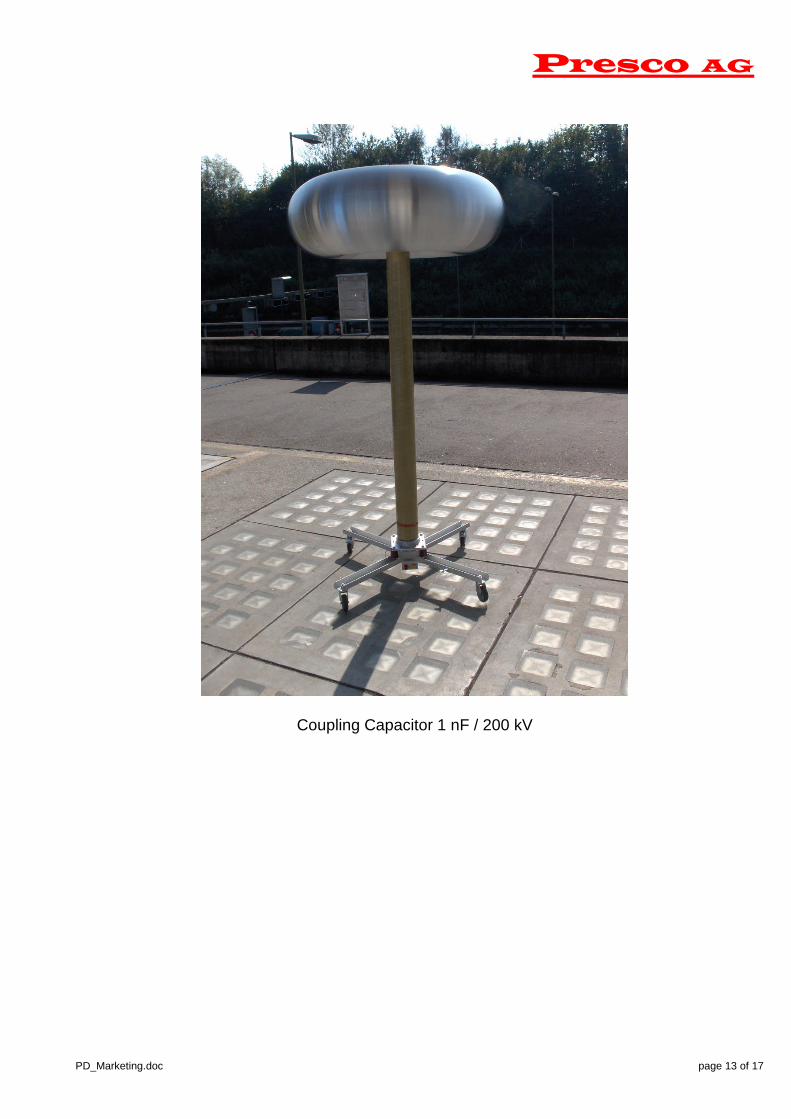
5.1 Coupling Capacitors
As a rule of thumb, the capacitance of the coupling capacitor is to be equal or higherthan the capacitance of the object to be tested. In many cases a coupling capacitorwith a capacitance of 1 nF (1'000 pF) will be suitable. Except for PD measurementon long cables one has to use a 10 nF one.
Presco can offer coupling capacitors rated e.g. from 10 kV up to nearly any voltage.
Coupling Capacitor 1 nF / 50 kV Coupling Capacitor 1 nF / 100 kV
Presco AG
PD_Marketing.doc page 13 of 17
Coupling Capacitor 1 nF / 200 kV

Presco AG
PD_Marketing.doc page 14 of 17
5.2 Multiplexers
For applications e.g. on three phase transformer, one has to measure PD on allthree phases. For such an application we offer multiplexers, either manuallycontrolled or remotely controlled by a PC.Ask us for an optimal solution according your requirements.
PD measurements on three phase transformers using a 3 channel multiplexer
ALL1
2
3
4 5 67
89
10
SELECTOR
Matching
Multiplexer
110
Adapter
PD-3
10 channel PD system with multiplexer
Coupling Device
and Multiplexer
3 Phase generator
OilOilOil
Oi l Oil Oil
Motor
Three-Phase regulating Transformer
pd3PhaseTrafo1.cdr
Filt
er
Filt
er
Filt
er
Three-PhaseFilter
Power for Instrument
Power from company line input
PD-4
Coupling Capacitors
Layout
Pult
HV Area
Grid+ Door
Power In
Power Out
D:\Eigene Dateien\corwork\Solutions/pd3PhaseTrafoSol1.cdr
Preco AG
Test Object
Presco AG
PD_Marketing.doc page 15 of 17
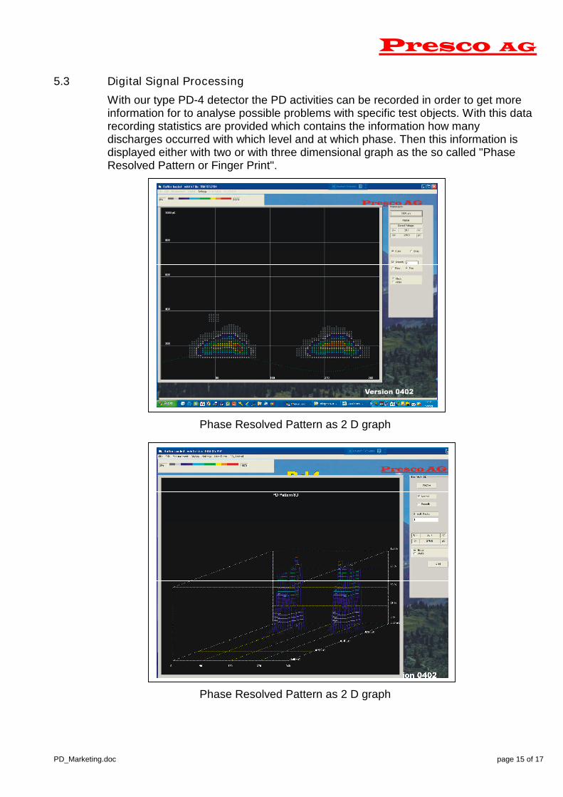
5.3 Digital Signal Processing
With our type PD-4 detector the PD activities can be recorded in order to get moreinformation for to analyse possible problems with specific test objects. With this datarecording statistics are provided which contains the information how manydischarges occurred with which level and at which phase. Then this information isdisplayed either with two or with three dimensional graph as the so called "PhaseResolved Pattern or Finger Print".
Phase Resolved Pattern as 2 D graph
Phase Resolved Pattern as 2 D graph
Presco AG
PD_Marketing.doc page 16 of 17
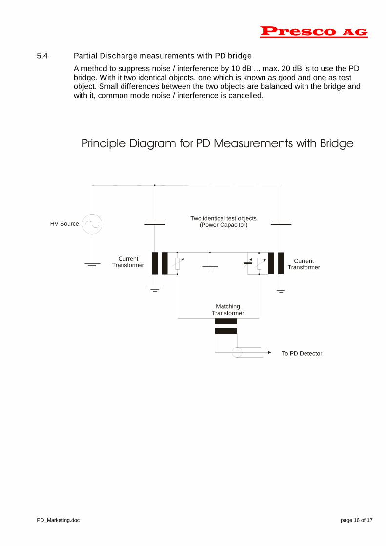
5.4 Partial Discharge measurements with PD bridge
A method to suppress noise / interference by 10 dB ... max. 20 dB is to use the PDbridge. With it two identical objects, one which is known as good and one as testobject. Small differences between the two objects are balanced with the bridge andwith it, common mode noise / interference is cancelled.
HV Source
To PD Detector
Two identical test objects(Power Capacitor)
Principle Diagram for PD Measurements with Bridge
CurrentTransformer
CurrentTransformer
MatchingTransformer

Presco AG
PD_Marketing.doc page 17 of 17
6 Noise / Interference / Back Ground Noise Level
As it is well known, the purpose of PD measurement is to measure small insulationdefects. PD is expressed in pC (pico Coulomb) which is a very small quantity (pico isequal to a factor 10-12). A PD impulse is an very fast transient of some nano secondsup to some micro seconds. Such an impulse has a spectra beginning at some KHzup to max. 1 MHz. A PD detector according to IEC60270 has a frequency band from20 kHz up to e.g. 200 kHz (or 400 kHz). As one can imagine, all signals inside thisfrequency band might be picked up by the PD detector / system asnoise/interference. Because one cannot distinguish between impulses / signals ofinterference and real PD impulses, the noise / interference is interpreted as PD andthis leads to the problem that PD of a specific object cannot be detected becausenoise / interference is higher that the real PD signal. In this case we are talking abouta too high back ground noise level.
Facts to be considered :
Back ground noise level has NOTHING to do with a specific PD detector.Todays PD detectors have an internal noise of approx. 0.3 pC only (far lowerfor cable PD systems).
In an industrial environment there are always some interference sources.
Most important is a correct test set-up and a good grounding system.
A coupling capacitor with a too low capacitance will lead to low sensitivity anda high back ground noise level.
To overcome the noise / interference problem, there are two possibilities :
a) To use a PD detector with noise reduction features, such as different filters or atuneable narrow band filter, gating, PD bridge. Maybe this helps but please beaware that with such a system, the noise / interference is "playing" with theoperator every day. Although maybe the initial costs for the PD system are low,this is something expensive over the years if the time which is lost every day isconsidered
or
b) To be aware of noise / interference and to consider some initial costs to set-up thePD test system in order to have a suitable low back ground noise level. This waythe operator has newer to take care on interference any more and this will safecosts over the years.
In case the PD system is purchased from Presco, our customers can count on ourknow how to get a PD system as per the specific requirements. Our proposal is :
Specify the required back ground noise level considering the standards. E.g.for voltage transformers one has to verify a PD level of < 5 pC and with it theback ground noise should not exceed 2.5 pC.
Set-up the system as per our advises
Analyse the situation according our advises
Get the needed measures from us against the specific interference sources