parte 7.3 - demosaicingbattiato/mm1112/parte 7.3 - demosaicing.pdf · bayer cfa cfa image color...
TRANSCRIPT
Multimedia
Demosaicing
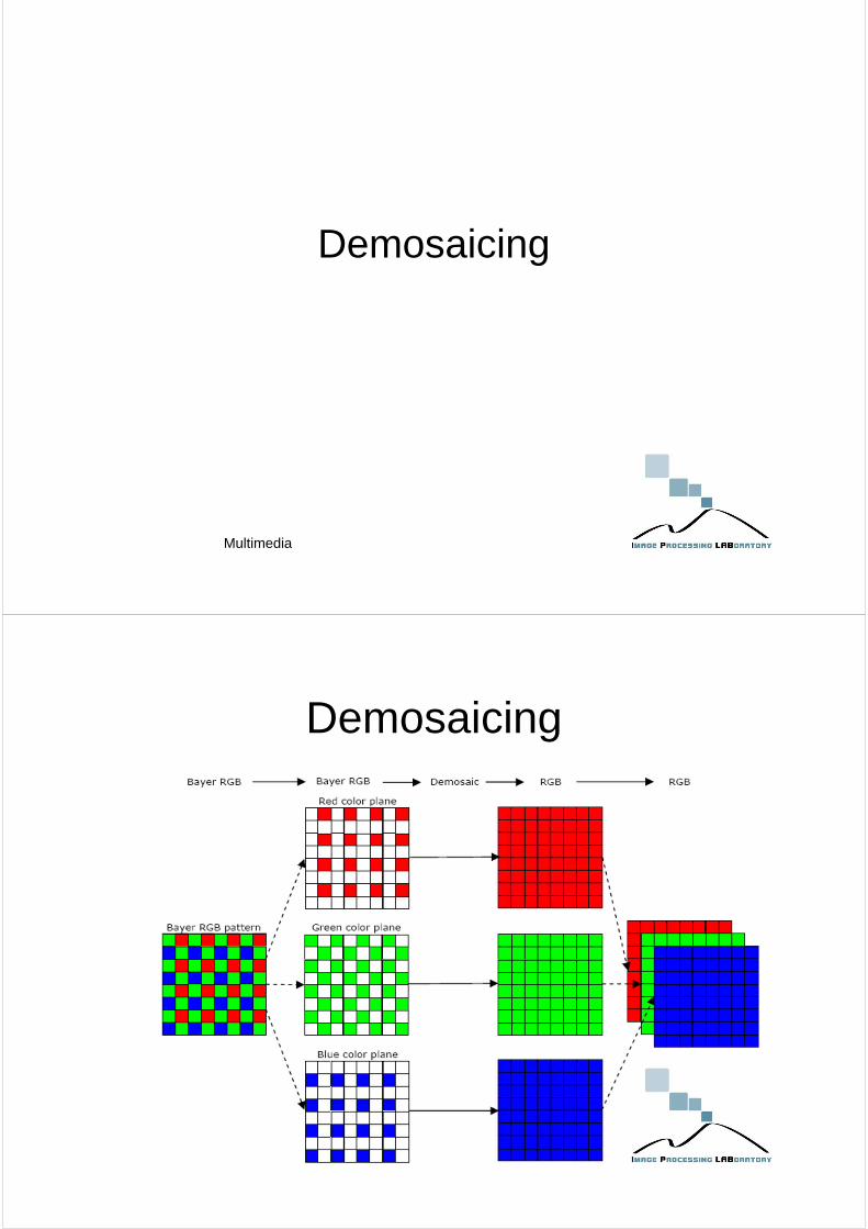
Demosaicing

Ideal InterpolationShannon Sampling Theorem:
When a “train of impulse”comb(x) is multiplied by f(x), it gives us a “sampledversion” off(x)
comb(x)f(x), in frequency domain, becomes convolution.Convolving with an impulse and shiftingcomb(s) * F(s) is replicating thespectrumF(s) at the different impulse locations.
Spatial aliasing in the form of a Moiré pattern

CFA
Bayer CFA
CFA image
Color artifacts

Zipper Effect
Bilinear interpolation Weighted interpolation
Processing

Color Interpolation - Nearest Neighbor Replication
• Each interpolated output pixel is assigned the value of thenearest pixel in the input image
• The nearest neighbor can be any one of the upper, lower, leftand right pixels
• For example, for a 3x3 block in green plane, we assume theleft neighboring pixel value is used to fill the missing ones
Color Interpolation - Bilinear Interpolation
• Interpolation of green pixels– The average of the upper, lower,
left and right pixel values isassigned as the G value of theinterpolated pixel
– G8 = (G3+G7+G9+G13) / 4• Interpolation of a red/blue pixel at a
green position– The average of two adjacent pixel
values in corresponding color isassigned to the interpolated pixel.
– B7 = (B6+B8) / 2– R7 = (R2+R12) / 2

Color Interpolation - Bilinear Interpolation
• Interpolation of a red/bluepixel at a blue/red position– The average of four adjacent
diagonal pixel values is assignedto the interpolated pixel
– R8 = (R2+R4+R12+R14) / 4
– B12 = (B6+B8+B16+B18) / 4
Bilinear

Lighthouseoriginal
LighthouseInterpolated color image

Lighthousered interpolatedwith bicubic interpolator
Lighthouseprefiltered red interpolatedwith bilinear interpolator

EDGE-DIRECTED INTERPOLATIONInterpolation of green pixels :
First, define two gradients, one in horizontal direction, the otherin vertical direction, for each blue/red position. For instance,consider B8 : define two gradients as
Define some threshold value TThe algorithm then can be described as:
The choice of T depends on the images and can have differentoptimum values from different neighborhoods. A particularchoice of T is
Demosaicking Approaches
Edge-directed interpolation
1. Calculate horizontal gradient ∆H = | (R3 + R7)/2 – R5 | 2. Calculate vertical gradient ∆V = | (R1 + R9)/2 – R5 | 3. If ∆H > ∆V,
G5 = (G2 + G8)/2Else if ∆H < ∆V,
G5 = (G4 + G6)/2 Else
G5 = (G2 + G8 + G4 + G6)/4
1
2
4 5 6 7
8
9
3
The edge-directed interpolation idea can be modified by using largerregions (around the pixel in question) with more complex predictors andby exploiting the texture similarity in different color channels.

Edge-Directed Interpolation
Edge-Directed Interpolation

Edge-Directed Interpolation
CONSTANT-HUE-BASED INTERPOLATION
Multimedia per Dispositivi Mobile

Adaptive interpolationUsing Laplacian For Enhancement: Use the second-order gradients of red/blue channels to enhance green channel.
Adaptive interpolation
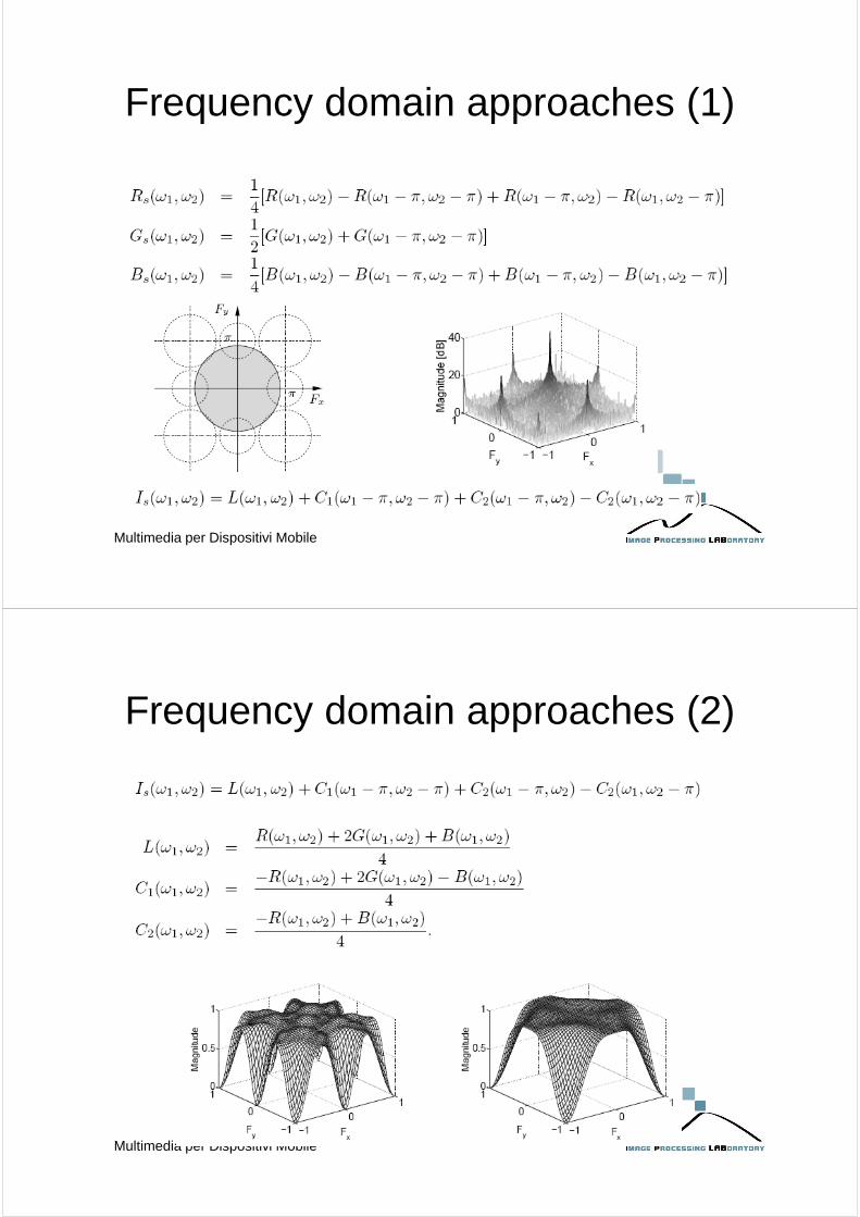
Frequency domain approaches (1)
Multimedia per Dispositivi Mobile
Frequency domain approaches (2)
Multimedia per Dispositivi Mobile

Post processing
Aliasing
• Color interpolation can provide images withobjectionable aliasing artifacts, such as “colorfringes” near sharp edges.
COLOR ACOLOR B
1 2 3 4 5 6 7 8 9 10
11
12
13
14
15
16
SHARP GREY EDGE
1 2 3 4 5 6 7 8 9 10
11
12
13
14
15
16
1 2 3 4 5 6 7 8 9 10
11
12
13
14
15
16
COLOR FRINGE ARTIFACT
Distribution of light intensity incident to an image sensing array
Illumination incident to the image sensing array in which alternate
pixels are overlapped by different colored filters
Distribution of linearly interpolated color light intensity values for the pixels of the image sensing array

Inter-channel differences
• Because of inter-channel correlation, the differencebetween two colors in a neighborhood is nearlyconstant;
• The difference between two colors rapidly increasesand decreases in the area of sharp grey edges,where color interpolation has introduced false colors;
COLOR A
COLOR B
1 2 3 4 5 6 7 8 9 10
11
12
13
14
15
16
Information signal corresponding to colors A and B
1 2 3 4 5 6 7 8 9 10
11
12
13
14
15
16
Difference between colors A and B for each pixel
Median filter• Median filter, over a given support (e.g. 3x3 mask),
operates to remove sharp spikes and valleys,leaving sharp monotonically increasing ordecreasing edges intact;
1 2 3 4 5 6 7 8 9 10
11
12
13
14
15
16
Color A minus color B, median filtered with a support of 5 pixels
( ){ }( ){ }
filtermediantheofsupporttheiswhere
,|
,|
ℜ
ℜ∈−=
ℜ∈−=
jiGBmedianv
jiGRmedianv
ijijBG
ijijRG
SHARP SPIKE
REMOVED

References
• http://www.site.uottawa.ca/~edubois/courses/CEG4311/slides/InterpolationRGBcomponents.ppt
• http://www.dmi.unict.it/~battiato/EI_MOBILE0708/EI_MOBILE0708.htm
• Gunturk BK, Glotzbach J, Altunbasak Y, Schafer RW,Mersereau RM. Demosaicking: Color Filter ArrayInterpolation. IEEE Signal Proc Magazine January 2005;22(1): 44-54.