part.20 mgb driver's handbook 1976, part 1.controls next mgb driver's handbook …...
TRANSCRIPT

Pedals(1)(2)(3)The pedals are arranged in the conventionel positions.The brake pedal operates the dual hydaulic braking system applying the brakes on allfour brakes, also when the ignition is switched on, bringing the stop warning lightsinto operation.
Gear lever(4)The gear positions are indicated on the lever knob. To engage reverse gear move thelever to the left in the neutral position until resistance is felt, apply further sidepressure to overcome the resistance and then pull the lever back to engage the gear.The reverse lights operate automatically when reverse is selected with the ignitionswitched on.Synchromesh engagement is provided on all forward gears.
Overdrive switch(when fitted)(5)A slide switch incorporated in the gear lever knob operates the overdrive. To engagethe overdrive move the switch rearward; to disengage, move the switch forward.
Hand brakeThe handbrake is one off the pull-up lever type, operating mechanically on the rearwheels only. To release the handbrake pull the lever up slightly, depress the button onthe end of the lever and push the lever down.
Part.20 MGB Driver's Handbook 1976, part 1.Controls Next
Page 1 sur 1Hi, I'm B, ... MG-B - hbintro2
6/06/2003http://www.xs4all.nl/~jdoddema/handbook/hbintro2.html
Key numberThe key number appears on the key, on the number tag supplied or on a label attachedto the windscreen on a new car. The steeringcolumn lock(4), if used properly, willgreatly reduce the possibility on the car being stolen.
UnlockingTo unlock the steering, insert the key and turn it to position "I". If the steering wheelhas been turned to engage the lock, slight movement of the steering wheel will assistdisengagement of the lock plunger.
Ignition and startTo switch on the ignition, turn the key to position to "II". Further movement againstspring resistance to position "III" operates the starter motor. Release the keyimmediately the engine starts.
LockingTo lock the steering, turn the key anti-clockwise to the position marked "I", press thebutton (5), turn the key in the "O" position and withdraw it.
Do not lubricated the steering lock.
Instruments
Speedometer(1)In addition to indicating the road speed this instrument also records the total distance(3) and the distance travelled for any particular trip(2).To reset the trip recorder, press the knob(4) and all the counters will return to zero.
Previous MGB Driver's Handbook 1976, part 2.Ignition/Starterswitch and steering lock Next
Page 1 sur 5Hi, I'm B, ... MG-B - hbintro3
6/06/2003http://www.xs4all.nl/~jdoddema/handbook/hbintro3.html
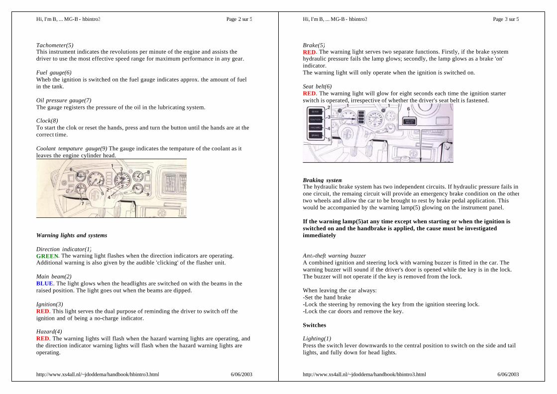
Tachometer(5)This instrument indicates the revolutions per minute of the engine and assists thedriver to use the most effective speed range for maximum performance in any gear.
Fuel gauge(6)Wheb the ignition is switched on the fuel gauge indicates approx. the amount of fuelin the tank.
Oil pressure gauge(7)The gauge registers the pressure of the oil in the lubricating system.
Clock(8)To start the clok or reset the hands, press and turn the button until the hands are at thecorrect time.
Coolant tempature gauge(9) The gauge indicates the tempature of the coolant as itleaves the engine cylinder head.
Warning lights and systems
Direction indicator(1)GREEN. The warning light flashes when the direction indicators are operating.Additional warning is also given by the audible 'clicking' of the flasher unit.
Main beam(2)BLUE. The light glows when the headlights are switched on with the beams in theraised position. The light goes out when the beams are dipped.
Ignition(3)RED. This light serves the dual purpose of reminding the driver to switch off theignition and of being a no-charge indicator.
Hazard(4)RED. The warning lights will flash when the hazard warning lights are operating, andthe direction indicator warning lights will flash when the hazard warning lights areoperating.
Page 2 sur 5Hi, I'm B, ... MG-B - hbintro3
6/06/2003http://www.xs4all.nl/~jdoddema/handbook/hbintro3.html
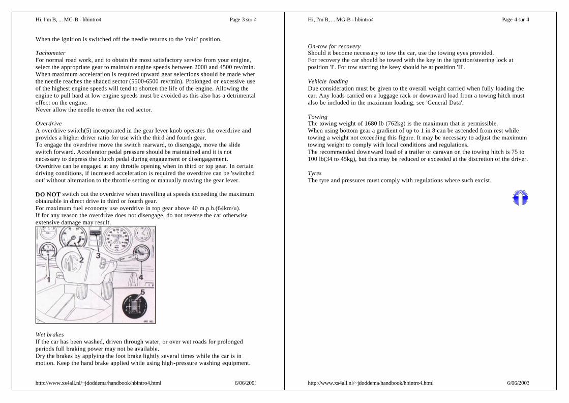
Brake(5)RED. The warning light serves two separate functions. Firstly, if the brake systemhydraulic pressure fails the lamp glows; secondly, the lamp glows as a brake 'on'indicator.The warning light will only operate when the ignition is switched on.
Seat belt(6)RED. The warning light will glow for eight seconds each time the ignition starterswitch is operated, irrespective of whether the driver's seat belt is fastened.
Braking systemThe hydraulic brake system has two independent circuits. If hydraulic pressure fails inone circuit, the remaing circuit will provide an emergency brake condition on the othertwo wheels and allow the car to be brought to rest by brake pedal application. Thiswould be accompanied by the warning lamp(5) glowing on the instrument panel.
If the warning lamp(5)at any time except when starting or when the ignition isswitched on and the handbrake is applied, the cause must be investigatedimmediately
Anti-theft warning buzzerA combined ignition and steering lock with warning buzzer is fitted in the car. Thewarning buzzer will sound if the driver's door is opened while the key is in the lock.The buzzer will not operate if the key is removed from the lock.
When leaving the car always:-Set the hand brake-Lock the steering by removing the key from the ignition steering lock.-Lock the car doors and remove the key.
Switches
Lighting(1)Press the switch lever downwards to the central position to switch on the side and taillights, and fully down for head lights.
Page 3 sur 5Hi, I'm B, ... MG-B - hbintro3
6/06/2003http://www.xs4all.nl/~jdoddema/handbook/hbintro3.html

Panel lamps(2)The panel lamps will function only when the side lamps are switched on. Turning theswitch knob clockwise switches on the panel lights; further clockwise movement ofthe knob increases the light brilliance.
Hazard warning(3)To use the direction indicators as a hazard warning to other road users, press the endof the switch rocker, when all the direction indicators, their warning lights and thehazard warning light will operate together, irrespective or whether the ignition key ison or off.The green illumination on the face of the switch glows when the panel lights areswitched on. Return the switch to the off position to cancel the warning.
Blower switch and heater controls(4)See "Heating and Ventilating".
Courtesy light(5)The courtesy light is controlled by a switch in the light and by a switch fitted to eachdoor pillar. With the doors closed the light may be switched on by pressing the frontedge of the lens which acts as a rocker switch.Press the rear edge of the lens to switch off the light. Opening either door will switchon the light, and closing the door will extinguish the light.
Cigar-lighter(6)To operate, press the knob inwards and release. When the element has becomesufficiently heated the lighter will be partially ejected, and may be withdrawn for use.The rim of the cigar-lighter il illuminated when the panel lights are switched on.
Column switch
Direction indicators, main beam and horn control
Direction indicatorsThe switch operates the indicators only when the ignition is switched on.Move the lever to position "A" when turning left and to position "B" when turning
Page 4 sur 5Hi, I'm B, ... MG-B - hbintro3
6/06/2003http://www.xs4all.nl/~jdoddema/handbook/hbintro3.html
right. After making a turn the signal is self-cancelled when the steering-wheel isreturned to the straight-ahead position.The switch lever may be held against spring pressure to select either left or rightindicator and will cancel the indication immediately it is released without movementof the steering wheel.A visual warning of a front of rear bulb failure is given when, after switching on aindicator, the warning lamp and the serviceable bulb on the affected side give acontinuous light.
Headlamp dipperWith the headlamps switched on at the lighting switch, move the lever forward ("C")to use the main beams; the warning light will glow (BLUE). Return the lever to themidway position to dip the beams.
Headlamp flasherLift the lever towards the steering wheel("D") to flash the headlamps irrespective ofwhether they have been switched on a at the lighting switch or not.
HornsPress the end of the lever inwards ("E') to sound the horns.
Windscreen washer and wiper control
Windscreen washerPress the end of the lever inwards("F") to operate the washer jets.In cold weather the washer reservoir should be filled with a mixture of water and arecommended washer solvent to prevent the water freezing.
Windscreen wiperMove the lever upwards("G") and then release it to obtain a single wipe. The leverwill return to the 'off'-position and the blades will park automatically at the completionof the wipe.To operate the wipers at normal speed move the lever down to the first position("H")and to the second position("J") when a higher speed is required.NOTE: neither the windscreen wiper nor the washer can operate until the ignition hasbeen switched on.
Page 5 sur 5Hi, I'm B, ... MG-B - hbintro3
6/06/2003http://www.xs4all.nl/~jdoddema/handbook/hbintro3.html

The following instructions are a guide for starting, running and loading the car, andincludes notes on the use of controls and the indicators of the instruments.
Running in .The treatment given to the new car will have an important bearing on its subsequentlife, and engine speeds during this early period must be limited.The following instructions should be strictly adhered to:During the first 500 miles:DO NOT exceed 45 m.p.h.DO NOT operate at full throttle in any gear.DO NOT allow the engine to labour in any gear.
Choice of fuel.The engine has been designed to operate only on unleaded fuel. It is essential thatunleaded fuel is used otherwise serious damage can be caused in the catalic convertor.
Filling with fuel.The filler neck of the fuel tank is designed to accept fuel dispenser nozzles of the typespecified only for unleaded fuel. The dispenser nozzle must be inserted into the fillerneck sufficiently to open the trap door fot fuel to flow into the fuel tank.
Starting.Sit in the car, then wear and fasten the seat belts; this applies to both driver andpassenger.Switch on the ignition and check:-That the ignition warning lights glows.-That the fuel gauge registers.-Depress the throttle pedal fully and release.
Operate the starter. Do not depress the throttle pedal while the starter is operated.As soon as the engine is started check:-That the oil pressure gauge registers.-That the ignition warning lights has gone out.
When thirty seconds of starting the engine, quickly depress and release the throttlepedal to set the automatic choke to its correct position.
Induction chamber heater(1)An induction chamber heater is fitted and operates below 4'C. When starting belowthis temperature it is necessary to allow a warning up period of thirty seconds betweenswitching on the ignition and starting the engine.
Previous MGB Driver's Handbook 1976, part 3.Starting, runningand loading the car Next
Page 1 sur 4Hi, I'm B, ... MG-B - hbintro4
6/06/2003http://www.xs4all.nl/~jdoddema/handbook/hbintro4.html
Never leave the ignition switched on in excess of the recommended periods with theengine at rest.
Fuel pomp inertia switch.The electrical supply to the fuel pump is switched off by an inertia switch if the car issubjected to a moderate impact. The switch(1), shown in the off position, is locatedunder the fascia on the left -hand side. To reset the switch unscrew the three screws(2)to release the bottom panel(3) push the plunger(4) into the switch and refit the bottompanel.
StarterDo not operate the starter for longer than five or six seconds.To prevent damage the starter cannot be operated while the engine is running.If the engine fails to start, the ignition key must be returned to the off position beforethe starter can be operated again.If after a reasonable number of attempts the engine should fail to start, switch off theignition and investigate the cause. Continued use of the starter when the engine willnot start not only discharges the battery but may also damage the starter.
Ignition warning lampThe light(3) should glow when the engine is switched on, and go out and stay out atall times when the engine is running above normal idling speed. Failure to do soindicates a fault in the battery charging system. Check that the alternator drive belt iscorrectly tensioned before consulting your authorized Austin MG Dealer.
Oil pressure gaugeThe gauge(1) should register a pressure as soon as the engine is started up. Thepressure may rise above 80 lbf/in2 when the engine is started from cold, and as the oilis circulated and warmed the pressure should then drop to between 50 and 80 lbf/in2 atnormal running speeds and to between 10 and 25 lbf/in2 at idling speed.Should the gauge fail to register and pressure, stop the engine immediately andinvetigate the cause. Start by checking the oil level.
Temperature gaugeNormal operating temperature is reached when the pointer is at 'normal'. Overheatingmay cause serious damage. Should the pointer reach "H'(hot), stop the engine andinvestigate the cause. Check the cooling fan operating (see chapter 'Electrical'), thedrive belt tension, and when the system has cooled, check the coolant level.
Page 2 sur 4Hi, I'm B, ... MG-B - hbintro4
6/06/2003http://www.xs4all.nl/~jdoddema/handbook/hbintro4.html
When the ignition is switched off the needle returns to the 'cold' position.
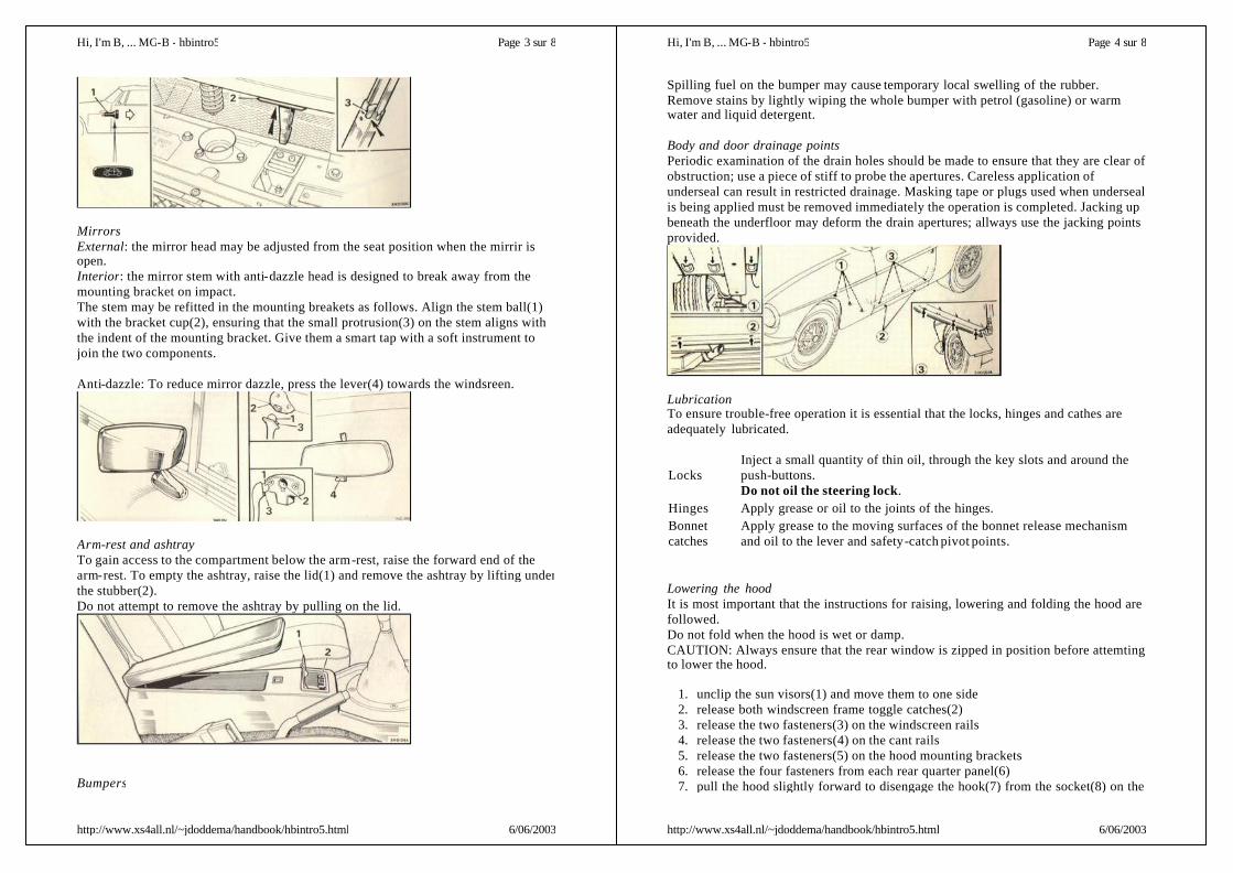
TachometerFor normal road work, and to obtain the most satisfactory service from your enigine,select the appropriate gear to maintain engine speeds between 2000 and 4500 rev/min.When maximum acceleration is required upward gear selections should be made whenthe needle reaches the shaded sector (5500-6500 rev/min). Prolonged or excessive useof the highest engine speeds will tend to shorten the life of the engine. Allowing theengine to pull hard at low engine speeds must be avoided as this also has a detrimentaleffect on the engine.Never allow the needle to enter the red sector.
OverdriveA overdrive switch(5) incorporated in the gear lever knob operates the overdrive andprovides a higher driver ratio for use with the third and fourth gear.To engage the overdrive move the switch rearward, to disengage, move the slideswitch forward. Accelerator pedal pressure should be maintained and it is notnecessary to depress the clutch pedal during engagement or disengagement.Overdrive can be engaged at any throttle opening when in third or top gear. In certaindriving conditions, if increased acceleration is required the overdrive can be 'switchedout' without alternation to the throttle setting or manually moving the gear lever.
DO NOT switch out the overdrive when travelling at speeds exceeding the maximumobtainable in direct drive in third or fourth gear.For maximum fuel economy use overdrive in top gear above 40 m.p.h.(64km/u).If for any reason the overdrive does not disengage, do not reverse the car otherwiseextensive damage may result.
Wet brakesIf the car has been washed, driven through water, or over wet roads for prolongedperiods full braking power may not be available.Dry the brakes by applying the foot brake lightly several times while the car is inmotion. Keep the hand brake applied while using high-pressure washing equipment.
Page 3 sur 4Hi, I'm B, ... MG-B - hbintro4
6/06/2003http://www.xs4all.nl/~jdoddema/handbook/hbintro4.html
On-tow for recoveryShould it become necessary to tow the car, use the towing eyes provided.For recovery the car should be towed with the key in the ignition/steering lock atposition 'I'. For tow starting the keey should be at position 'II'.
Vehicle loadingDue consideration must be given to the overall weight carried when fully loading thecar. Any loads carried on a luggage rack or downward load from a towing hitch mustalso be included in the maximum loading, see 'General Data'.
TowingThe towing weight of 1680 lb (762kg) is the maximum that is permissible.When using bottom gear a gradient of up to 1 in 8 can be ascended from rest whiletowing a weight not exceeding this figure. It may be necessary to adjust the maximumtowing weight to comply with local conditions and regulations.The recommended downward load of a trailer or caravan on the towing hitch is 75 to100 lb(34 to 45kg), but this may be reduced or exceeded at the discretion of the driver.
TyresThe tyre and pressures must comply with regulations where such excist.
Page 4 sur 4Hi, I'm B, ... MG-B - hbintro4
6/06/2003http://www.xs4all.nl/~jdoddema/handbook/hbintro4.html

KeysThree keys and a duplicate set are provided, the large key for the steering lock/ignitionswitch, the larger all metal key for the glove box, and the small all metal key for thedoor locks and the luggage compartment.To reduce the possibility of theft, locks are not marked with a number.NOTE THE KEY NUMBERS IMMIDEATELY on taking delivery of the car.
Window regulatorsTo open a door window, turn the handle regulator (1) to obtain the opening required.Door locksBoth front doors may be locked from outside the car with the small key provided, andlocked from inside the car with the door locking latch.
To unlock the front doors from the outside, insert the key into the lock and turn ittowards the front of the car, return it to the upright position and withdraw it. Grasp thehandle and depress the button(2) to open the door.To lock the front doors from the outside, turn the key towards the rear of the car,return it to the upright position an d withdraw it.To lock the doors from inside the car, close the door and move the locking latch(3)towards the rear of the car. To open the door, move the locking latch towards the frontof the car and pull the release lever(4) rearwards.The doors can be opened from the outside when the locking latch is in the forwardposition. The locking latch cannot be set to the lock position while the door is open.
Front ventilator windowsTo open, move the catch lever(1) upwards and push the window outwards. To close,pull the catch inwards, and then push it forward until the catch is in the lockedposition.
GloveboxTo unlock, insert the key, turn it clockwise, and depress the lock plunger to open theglovebox.To lock, close the glovebox, turn the key anti-clockwise and withdraw the key from
Previous MGB Driver's Handbook 1976, part 4.Locks, fittingand body Next
Page 1 sur 8Hi, I'm B, ... MG-B - hbintro5
6/06/2003http://www.xs4all.nl/~jdoddema/handbook/hbintro5.html
the lock.
Luggage compartmentTo open, insert the key and turn it anti-clockwise, depress the lock plunger and raisethe lid. When fully raised the support stay will automatically spring into engagementand the lid will be held in the open position.Raising the luggage compartment lid automatically switches on the light.To close, raise the lid slightly, push the catch(1) on the bonnet stay forward to releasethe locking mechanism, and lower the lid. To lock insert the key and turn clockwise(arrowed) and withdraw the key.
BonnetTo raise the bonnet, pull the knob(1) located inside the car on the left hand side belowthe fascia panel.Press up the safety catch(2) under the front of the bonnet. Raise the bonnet and whenfully raised the support stay will automatically spring into engagement and the bonnetwill be held in open position.To close, raise the bonnet slightly, push the catch(3) on the bonnet stay rearwards torelease the locking mechanism, and lower the bonnet. Apply light pressure with thepalms of the hands at the front cormers and press down quickly; undue force is notnecessary and may cause damage. The safety catch and lock will be heard to engage.
Page 2 sur 8Hi, I'm B, ... MG-B - hbintro5
6/06/2003http://www.xs4all.nl/~jdoddema/handbook/hbintro5.html
MirrorsExternal: the mirror head may be adjusted from the seat position when the mirrir isopen.Interior: the mirror stem with anti-dazzle head is designed to break away from themounting bracket on impact.The stem may be refitted in the mounting breakets as follows. Align the stem ball(1)with the bracket cup(2), ensuring that the small protrusion(3) on the stem aligns withthe indent of the mounting bracket. Give them a smart tap with a soft instrument tojoin the two components.
Anti-dazzle: To reduce mirror dazzle, press the lever(4) towards the windsreen.
Arm-rest and ashtrayTo gain access to the compartment below the arm-rest, raise the forward end of thearm-rest. To empty the ashtray, raise the lid(1) and remove the ashtray by lifting underthe stubber(2).Do not attempt to remove the ashtray by pulling on the lid.
Bumpers
Page 3 sur 8Hi, I'm B, ... MG-B - hbintro5
6/06/2003http://www.xs4all.nl/~jdoddema/handbook/hbintro5.html
Spilling fuel on the bumper may cause temporary local swelling of the rubber.Remove stains by lightly wiping the whole bumper with petrol (gasoline) or warmwater and liquid detergent.
Body and door drainage pointsPeriodic examination of the drain holes should be made to ensure that they are clear ofobstruction; use a piece of stiff to probe the apertures. Careless application ofunderseal can result in restricted drainage. Masking tape or plugs used when undersealis being applied must be removed immediately the operation is completed. Jacking upbeneath the underfloor may deform the drain apertures; allways use the jacking pointsprovided.
LubricationTo ensure trouble-free operation it is essential that the locks, hinges and cathes areadequately lubricated.
Lowering the hoodIt is most important that the instructions for raising, lowering and folding the hood arefollowed.Do not fold when the hood is wet or damp.CAUTION: Always ensure that the rear window is zipped in position before attemtingto lower the hood.
1. unclip the sun visors(1) and move them to one side2. release both windscreen frame toggle catches(2)3. release the two fasteners(3) on the windscreen rails4. release the two fasteners(4) on the cant rails5. release the two fasteners(5) on the hood mounting brackets6. release the four fasteners from each rear quarter panel(6)7. pull the hood slightly forward to disengage the hook(7) from the socket(8) on the
LocksInject a small quantity of thin oil, through the key slots and around thepush-buttons.Do not oil the steering lock.
Hinges Apply grease or oil to the joints of the hinges.Bonnetcatches
Apply grease to the moving surfaces of the bonnet release mechanismand oil to the lever and safety-catch pivot points.
Page 4 sur 8Hi, I'm B, ... MG-B - hbintro5
6/06/2003http://www.xs4all.nl/~jdoddema/handbook/hbintro5.html
body side panel8. move the seat tilt catch forward and incline the seat backs towards the front of
the car
1. raise the hood header rail until it is poised approx. midway over the dooraperture
2. disengage the hood rear rail from the anchor plates(9) on the tonneau panel3. fold each quarter-light(10) onto the back-light and continue the fold in the
material forward to the header rail(11).Ensure that the fold is made in thehood material between the quarter-light and the back-light. Failure to dothis may cause permanent damage to the back-light material .
4. push the header rail(11) rearwards5. at the same time draw the back-light and hood material(12) out over the luggage
compartment lid ensuring that the hood material does not become trappedbetween the hood sticks.
6. fully lower the hood. Fold the two windscreen frame toggle catches(13)rearwards to prevent them damaging the back-light
7. roll the rear window and hood material forward over the folded hood. Positionand secure the two retaining straps(14)
8. replace the sun visors and return the seat back-rests to their original position9. fit the hood cover or tonneau cover
Raising the hood
1. remove the hood cover or tonneau cover2. move the seat catch forward and incline the seat back towards the front of the car3. unclip the sun visors and move to one side4. release the two retaining straps(14) and unfold the rear window and hood
Page 5 sur 8Hi, I'm B, ... MG-B - hbintro5
6/06/2003http://www.xs4all.nl/~jdoddema/handbook/hbintro5.html
material rearwards over the luggage compartment5. raise the header rail(11) and unfold the hood. Engage the rear rail in the anchor
plates(9). Pull the hood slightly forwards and engage each hook(7) in its socket(8) on the body side panel. Position the header rail on the windscreen ensuringthe rail seal is forward of the seal flange. Secure the windscreen frame togglecatchers and fasteners(3), (4), and (5) inside the car.
6. secure the fasteners at each rear quarter7. reposition the seats and sun visors
Rear windowThe rear window may be folded down when extra ventilation is required with the hoodin the raised position.Undo the zip, moving it around the rear window to the left side of the hood. Fold thewindow panel down, avoiding creasing or buckling the transparent window material.
Fitting the hood cover
1. assemble the hood cover rail(15) and fit it into the hood support sockets with thecross-rod towards the rear
2. lay the hood cover over the support rail3. engage the hood cover rear rails in the anchor plates(16) on the tonneau panel4. pull the cover slightly forwards and engage each side hook in its socket(17) on
the body panel5. secure the fasteners(18) at each quarter side panel6. secure the fasteners(19) on the heel board
Removing the hood coverReverse the fitting procedure.
Tonneau coverFitting.Assemble the hood cover rail(15) and fit it into the hood support socket with the cross-rod towards the rear. Lay the tonneau cover over the cockpit.Engage the tonneau cover rear rails in the anchor plates on the tonneau panel. Placethe pockets in the tonneau cover over the head restraints on the seats; it may benecessary to adjust the seat back to align the pockets in the cover with the headrestraints.Secure the tonneau cover to each rear quarter with the four fasteners(18), and thefastener(20) on the cover at the side zips.With the centre zip undon, extend the tonneau cover forward, fitting the forwardpocket over the steering-weel and securing to the fasteners(21) on each windscreenpillar, and the fastener(22) on the fascia panel top. Zip up the cover.
Usage.The centre zip allows the cover to be folded down to give access to the driving seat or
Page 6 sur 8Hi, I'm B, ... MG-B - hbintro5
6/06/2003http://www.xs4all.nl/~jdoddema/handbook/hbintro5.html

both seats. Undo the centre zip, release the press-studs on the fascia(21 and 22), andthe press-stud(20) at the side zips. Fold the cover down and inwards behind the seat.Move the seat tilt catch forward, and incline the seat back towards the front of the car.Secure the tonneau cover to the heel board, using the fastener on the flap. Return theseat back-rests to their original position.The side zips allow the seat belt to be used.
Removing.Reverse the fitting procedure.
StowageStowage bags are provided to protect the hood cover an dhood cover rail. The stowagebags together with the tool bag are stowed in the luggage compartment and securedwith the straps provided.
Hard topFittingRemove the hood. Fit the hard top side brackets into the hood support sockets andsecure with the bolts and spring washers.Position the hard top on the car, engaging the rear securing plates with the slottedanchor plates on the tonneau panel(inset), ensuring that the sealing rubber does notfoul the slots.Line up the hard top drip moulding with the rear wing top beading. Push the hard topfforwards and engage the toggle catch tongues in the sockets on the windscreen frame.Fit the bolts into the side fixing brackets; screw in but do not tightn.Ensure that thefront sealing rubber is correctly positioned forward on the windscreen frame. Adjustthe toggle catches to give adequate tension , tighten the securing bolts, fasten thecatches and lock them with the securing clipsRechech the sealing rubbers, measure gaps between hard top and body. If necessary
Page 7 sur 8Hi, I'm B, ... MG-B - hbintro5
6/06/2003http://www.xs4all.nl/~jdoddema/handbook/hbintro5.html
refit and tighten the bolts and clips.
RemovingUnlock and release the windscreen toggle fasteners. Remove the side fixing bolts.Raise the front of the hard top disengage the toggle fastener tongues from thewindscreen sockets, move the hard top to the rear to disengage the anchor plates, thenlift of the car. Remove the side fixing brackets from the hood support sockets.Assemble the fittings loosely to the hard top to prevent loss.
Page 8 sur 8Hi, I'm B, ... MG-B - hbintro5
6/06/2003http://www.xs4all.nl/~jdoddema/handbook/hbintro5.html

Seat adjustmentFront seats can be moved forward or backwards if the lever(1) located beneath thefront of each seat is pressed outwards; hold the lever in this position while the seatposition is adjusted.The locking pin is spring-loaded and will automatically lock the seat in the requiredposition when the lever is released.
Adjustable back-restThe angle of the seat back-rest may also be adjusted by easing the body weight fromthe seat back-rest, and moving the lever(2) in the direction of the arrow. Release thelever and ensure that the seat is locked in position by applying back pressure.
Access to rear seatsMove the seat catch(3) forward, and fold the back of the seat forwards. The catch willautomatically re-engage when the rear of the seat is moved back to the correct drivingposition.
Head restraintThe head restraint(4) may be raised or lowered as desired.To remove, lift the head restraint to its stop and withdraw by rocking it from side toside whilst pulling upwards.
Seat BeltsWarning systemThe seat belt warning system functions when the ignition/starter switch is operated.The 'fasten seatbelts' warning lamp will be switched on for eight seconds each time theignition/starter switch is operated.The warning buzzer will sound for eight seconds if the ignition/starter switch isoperated before the driver's seat belt is fastened.
WearingAlways wear a belt as a complete lap and diagonal assembly and never at any timewear it loosely, as it reduces its protection. Ensure that the belt is lying flat and is nottwisted . Always stow a seat belt that is not in use.Never attempt to use a seat belt for more than one person, even for small children.
Previous MGB Driver's Handbook 1976, part 5.Seats Next
Page 1 sur 2Hi, I'm B, ... MG-B - hbintro6
6/06/2003http://www.xs4all.nl/~jdoddema/handbook/hbintro6.html
Page 2 sur 2Hi, I'm B, ... MG-B - hbintro6
6/06/2003http://www.xs4all.nl/~jdoddema/handbook/hbintro6.html
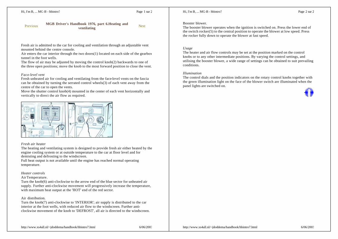
Fresh air is admitted to the car for cooling and ventilation through an adjustable ventmounted behind the centre console.Air enters the car interior through the two doors(1) located on each side of the gearboxtunnel in the foot wells.The flow of air may be adjusted by moving the control knob(2) backwards to one ofthe three open positions; move the knob to the most forward position to close the vent.
Face-level ventFresh unheated air for cooling and ventilating from the face-level vents on the fasciacan be obtained by turning the serrated control wheels(3) of each vent away from thecentre of the car to open the vents.Move the shutter control knob(4) mounted in the center of each vent horizontally andvertically to direct the air flow as required.
Fresh air heaterThe heating and ventilating system is designed to provide fresh air either heated by theengine cooling system or at outside temperature to the car at floor level and fordemisting and defrosting to the windscreen.Full heat output is not available until the engine has reached normal operatingtemperature.
Heater controlsAir Temperature.Turn the knob(6) anti-clockwise to the arrow end of the blue sector for unheated airsupply. Further anti-clockwise movement will progressively increase the temperature,with maximum heat output at the 'HOT' end of the red sector.
Air distribution.Turn the knob(7) anti-clockwise to 'INTERIOR'; air supply is distributed to the carinterior at the foot wells, with reduced air flow to the windscreen. Further anti-clockwise movement of the knob to 'DEFROST', all air is directed to the windscreen.
Previous MGB Driver's Handbook 1976, part 6.Heating andventilating Next
Page 1 sur 2Hi, I'm B, ... MG-B - hbintro7
6/06/2003http://www.xs4all.nl/~jdoddema/handbook/hbintro7.html
Booster blower.The booster blower operates when the ignition is switched on. Press the lower end ofthe switch rocker(5) to the central position to operate the blower at low speed. Pressthe rocker fully down to operate the blower at fast speed.
UsageThe heater and air flow controls may be set at the position marked on the controlknobs or to any other intermediate positions. By varying the control settings, andutilising the booster blower, a wide range of settings can be obtained to suit prevailingconditions.
IlluminationThe control dials and the position indicators on the rotary control knobs together withthe green illumination light on the face of the blower switch are illuminated when thepanel lights are switched on.
Page 2 sur 2Hi, I'm B, ... MG-B - hbintro7
6/06/2003http://www.xs4all.nl/~jdoddema/handbook/hbintro7.html

InteriorCarpetsClean with a semi-stuff brush or a vacuum cleaner, preferably before washing theoutside of the car. Occasionally give the carpets a thorough cleaning with a suitableupholstery cleaner. Carpets must not be 'dry -cleaned'.
Plastic faced upholsteryClean with diluted upholstery cleaner. Spot clean with upholstery cleaner spread thinlyover the surface with a brush or cloth, leave for five minutes, then wipe over with adamp sponge or cloth.
Nylon face upholsteryRemove loose dirt with a brush or vacuum cleaner. The nylon pile has beenchemically treated to resist soiling and care must be taken when cleaning. To remove astain, apply a nylon cleaner, then pat and wipe with a clean cloth in the direction of thepile until the stain is removed. DO NOT RUB. When dry, gently brush against thepile, then with the pile.
BodyRegular care of the body finish is necessary if the new appearance of the car exterior isto be maintained against the effects of air pollution, rain and mud.
Wash the bodywork frequently, using a soft sponge and plenty of water containing carshampoo. Large deposists of mud must be softened with water before using thesponge.Smears should be removed by a second wash in clear water, and with the sponge ifnecessary. When dry, clean the surface of the car with a damp chamois-leather.In addition to the regular maintenance , special attention is required if the car is drivenin extreme conditions such as sea spray or on salted roads. In those conditions andwith other forms of severe contamination an additional washing operation is necessarywhich should include underbody hosting.Any damaged areas should be immediately coverd with paint and a complete repaireffected as soon as possible. Before touching-in light scrathes and abrasions withpaint, thoroughly clean the surface. Use petrol/white spirit to remove the spots ofgrease or tar.
Bright trimNever use a abrasive on stainless, chromium, aluminium, or plastic parts and on noaccount clean them with metal polish.Remove the spots of grease and tar with petrol/white spirit and wash frequently withwater containing car shampoo. When the dirt has been removed polish with a cleandry cloth or chamois -leather until bright.
Previous MGB Driver's Handbook 1976, part 7.Cleaning Next
Page 1 sur 2Hi, I'm B, ... MG-B - hbcare1
6/06/2003http://www.xs4all.nl/~jdoddema/handbook/hbcare1.html
Any slight tarnish found on stainless or plated components which have not receivedregular attention may be removed with chrome cleaner. An occasional application oflight mineral oil or grease will help to preserve the finish, particularly during thewinter when salt may be used on the roads, but these protectives must not be appliedto plastic finishes.
Page 2 sur 2Hi, I'm B, ... MG-B - hbcare1
6/06/2003http://www.xs4all.nl/~jdoddema/handbook/hbcare1.html

The pressurized cooling system incorporates an expansion tank, making the need forregular topping-up unnecessary. The expansion tank, connected to the top of theradiator, receives the normal overflow of coolant when the system is in the process ofheating up. When the temperature in the radiator is reduced and the overflow thereturns to the radiator.
Cooling fanFor information on the electrically driven cooling fan see the chapter "electrical".
CheckingThe coolant level must only be checked when the system is cold. Remove theexpansion tank cap to check the coolant level which must be maintained to the half-full point of the tank.
If coolant is not displaced or the level in the expansion tank has fallen appreciablysince the last periodical check, a leak in the cooling system or overheating must besuspected.
Topping upWarning: As injury could be caused while the system is hot by escaping steam orcoolant the filler plug(1) must not be removed before the pressure relief cap(2).If the system is hot, protect the hands against escaping steam, turn the expansion tankrelief cap(2) slowly until the stop is felt and allow the pressure in the system to escapegradually, then remove the cap. Add coolant to the expansion tank to the half-fullpoint, and refit the cap. Remove the filler plug(1) and add coolant to bring the level tothe top of the filler neck; refit the plug.
DrainingTo drain the cooling system, stand the car on level ground, remove the expansion tankcap(1), and the filler plug(2) from the coolant outlet elbow. Slacken the hose clip anddisconnect the bottom hose(3) at its connection to the radiator.Remove the drain plug(4) on the cylinder block.Collect the coolant in a clean container if it to be used again as cars are filled with a 50per cent solution of anti-freeze before they leave the factory.Leave a reminder on the vehicle to the effect that the cooling has been drained. Owingthe location of the car heater and the expansion tank they cannot be drained with thecooling system. Anti-freeze must be used in the cooling system when freezingconditions are likely to be encountered.
FillingRefit the bottom hose and close the engine drain tap. Check that all hose connectionsare tight. Turn the heater temperature control knob to 'HOT' to open the heater valve.
Previous MGB Driver's Handbook 1976, part 8.The coolingsystem Next
Page 1 sur 2Hi, I'm B, ... MG-B - hbcare2
6/06/2003http://www.xs4all.nl/~jdoddema/handbook/hbcare2.html
Top up the coolant in the expansion tank so that the tank is half-full. Refit the cap(1).Fill the system through the filler neck and bring the level up to the bottom of thethreads. Refit the filler plug(2).Start up and run the engine until the top radiator hose is warm and switch of theengine. Turn the expansion cap to its safety stop to release the pressure. Top up theexpansion tank to half-full, and refit the cap.Remove the radiator filler plug and top up once more to the bottom of the threads.Refit the filler plug.CAUTION: The system operates at a pressure of 15 lb/in2(1 kg/cm2) anf\d thefigure '15' is marked on the expansion tank cap.
Frost precautionsWater expands when it freezes, and if precautions are not taken there is a considerablerisk of bursting the radiator, cylinder block, or heater. The heater unit cannot bedrained with the cooling system; it is therefore essential to use anti-freeze in thecooling system in freezing conditions.Anti-freeze can remain in the cooling system for two years provided that the specificgravity of the coolant is checked periodically and anti-freeze added as necessary. Thespecific gravity check should be carried out by an authorized dealer.After the second year the system should be drained and flushed by a inserting a hosein the filling orifice and allowing water to flow through until clean. Make sure that thecooling system is water-tight, examine all joints and replace any defective hose with anew one. Refill with the appropriate anti-freeze solution, and add 0,2 litre of neat anti-freeze to the expansion tank.Anti-freeze(%)
Commences tofreeze('C)
Frozensolid9('C)
2533 1/250
-13-19-36
-26-36-48
Page 2 sur 2Hi, I'm B, ... MG-B - hbcare2
6/06/2003http://www.xs4all.nl/~jdoddema/handbook/hbcare2.html

Jacking upThe jack is designed to lift one side of the car at a time. Apply the hand brake andblock the wheels on the opposite side to that being jacked: use a wood block jammedtight against the tyre thread.
Remove the jack socket plug. Insert the filling arm(1) of the jack into the socketlocated in the door sill panel. Make certain that the jack lifting arm is pushed fully intothe socket and that the base of the jack is on firm ground. The jack should lean slightlyoutwards at the top to allow for the radial movement of the car as it is raised.WARNING: Do not work beneath the vehicle with the lifting jack as the solemeans of support.Place suitable supports under the front side members or rear axle to give adequatesupport and safety while working.
Jack maintenanceIf the jack is neglected it may be difficult to use in a roadside emergency. Examine itoccasionally, clean off accumulated dust, and lightly oil the thread to prevent theformation of rust.
ROAD WHEELSWheel nutsOwners are recommended to check the wheel nuts for tightness each week in additionto checking the other items listed. Take car not to overtighten. Torque wrench settingto 8,3-9 kgfm.
Pressed typeRemoving and fittingSlacken the four nuts securing the road wheel to the hub; turn anti-clockwise to loosenand clockwise to tighten. Raise the car with the jack to lift the wheel clear of theground and remove the nuts. Withdraw the road wheel from the hub.When refitting the road wheel locate the wheel on the hub, lightly tighten the nuts(2)with the wheel nut spanner (securing nuts must be fitted with the taper side towardsthe wheel), and lower the jack. Fully tighten the wheel nuts, tighten them diagonallyand progressively, at the same time avoid over-tighting.The wheel centre trim(3) must be removed and fitted to the wheel in use. Replace thewheel disc and the jack socket plug.
Previous MGB Driver's Handbook 1976, part 9.Wheels and tyres Next
Page 1 sur 3Hi, I'm B, ... MG-B - hbcare3
6/06/2003http://www.xs4all.nl/~jdoddema/handbook/hbcare3.html
Wired type(if fitted)Removing and fittingUse the spanner and hammer to slacken and tighten the octagonal nuts. Always jackup a wheel before using the tools, and always tighten the hub nuts fully. Hub nuts aremarked 'LEFT' or "RIGHT' to show which side of the car they must be fitted, and alsowith the word 'UNDO' and a arrow.
Before replacing a wheel wipe all serrations, threads, and cones of the wheel and huband then lightly coat them with a grease. If a forced change is made on the road,remove, clean, and grease as soon as convenient.
MaintenanceWhen the car is new, after the first long run over 50 miles of short runs, jack up thewheels and use the hammer and spanner to make sure that the nuts are tight.
Spare wheelThe spare wheel is stowed in the well of the luggage compartment.Unscrew the clamp plate(3) to release the spare wheel.When refitting, position the wheel face down in the well of the luggage compartmentand retain in position with the clamp plate.The spare wheel tyre on new cars is inflated above the recommended runningpressure. The pressure must be checked and adjusted before use.
TYRESMarkingsTyres are marked with the maximum load and inflation pressure figures. When fittingreplacement tyres ensure that they are to the same specification and marking.
Tyre pressuresCheck the pressure weekly, using a Tyre Pressure Gauge, when the tyres are cold.Recommendations are given in 'General Data'.
Valves and capsSee that the valve caps are screwed down firmly by hand. Do not use tools.
Tyre care
Page 2 sur 3Hi, I'm B, ... MG-B - hbcare3
6/06/2003http://www.xs4all.nl/~jdoddema/handbook/hbcare3.html

The tyres should be inspected at frequent intervals for damage and wear. Excessivelocal distortion as a result of striking a kerb, a loose brick, a deep hole, etc. may causethe casing cords to fracture. Every effort should be made to avoid such obstacles.Any oil or grease which may get onto your tyres should be cleaned off by using petrol(fuel) sparingly. Do not use paraffin.
Page 3 sur 3Hi, I'm B, ... MG-B - hbcare3
6/06/2003http://www.xs4all.nl/~jdoddema/handbook/hbcare3.html
Front brake padsWear on the front brake friction pads(arrowed) is automatically compensated forduring braking operations and manual adjustment is therefore not required.If the wear on one pad is greater than on the other their operating positions should bechanged over by you authorized Austin MG dealer.
Remove the road wheel to gain clear access to the pads for inspection.The pads must be renewed when the lining material has worn to the minimumpermissible thickness of 1.6mm or will have done so before the next regularinspection is due. Special equipment is required to renew the brake pads; this wordshould be entrusted to your authorized Austin MG Dealer.After fitting new pads, within the limits of safety, heavy braking should be avoided fora few days to allow the pads to bed in.
Rear brakesExcessive brake pedal travel is an indication that the rear brake shoes requireadjusting. The brake shoes on both rear wheels must be adjusted to regain even andefficient braking.
Adjusting. Chock the front wheels, fully release the hand brake and jack up each rearwheel in turn, placing suitable supports beneath the vehicle. Turn the adjuster(1) in aclockwise direction(viewed from the centre of the car), using a Brake AdjustingSpanner until the brake shoes lock the wheel, the turn the adjuster back until thewheel is free to rotate without the shoes rubbing. Repeat the adjustment on the otherrear brake.
Hand brakeThe hand brake is automatically adjusted with the rear brakes. If there is excessivemovement of the rear brake lever, consult your authorized Austin MG Dealer.To lubricate , charge the nipple(2) on the hand brake cable with one of therecommended greases.
Replacing brake-shoes or pads
Previous MGB Driver's Handbook 1976, part 10.Brakes andmaster cylinders Next
Page 1 sur 3Hi, I'm B, ... MG-B - hbcare4
6/06/2003http://www.xs4all.nl/~jdoddema/handbook/hbcare4.html
When it becomes necessary to renew brake-shoes or pads it is essential that onlygenuine replacements, with the correct grade of lining, are used. Always fit new shoesor pads as complete axle sets, never individually or as a single wheel set. Seriousconsequences could result out -of-balance braking due to mixing off linings.Replacement brake shoes or pads are obtainable from your authorized Austin MGDealer.
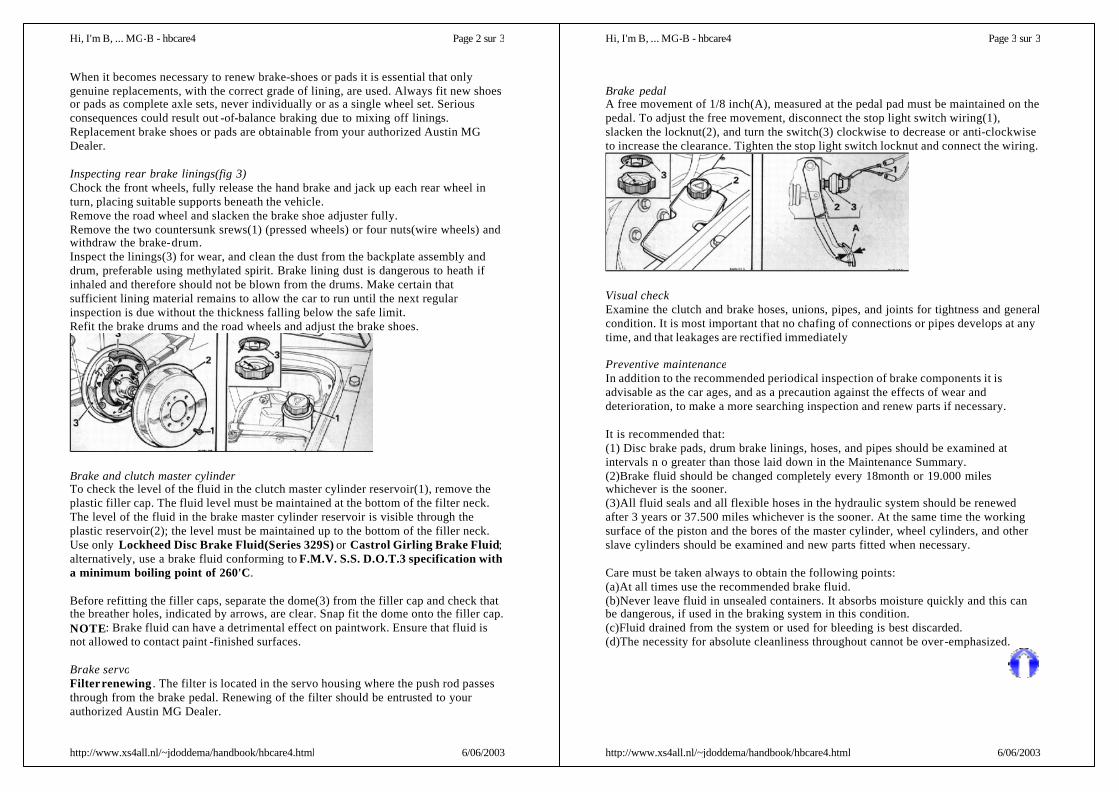
Inspecting rear brake linings(fig 3)Chock the front wheels, fully release the hand brake and jack up each rear wheel inturn, placing suitable supports beneath the vehicle.Remove the road wheel and slacken the brake shoe adjuster fully.Remove the two countersunk srews(1) (pressed wheels) or four nuts(wire wheels) andwithdraw the brake-drum.Inspect the linings(3) for wear, and clean the dust from the backplate assembly anddrum, preferable using methylated spirit. Brake lining dust is dangerous to heath ifinhaled and therefore should not be blown from the drums. Make certain thatsufficient lining material remains to allow the car to run until the next regularinspection is due without the thickness falling below the safe limit.Refit the brake drums and the road wheels and adjust the brake shoes.
Brake and clutch master cylinderTo check the level of the fluid in the clutch master cylinder reservoir(1), remove theplastic filler cap. The fluid level must be maintained at the bottom of the filter neck.The level of the fluid in the brake master cylinder reservoir is visible through theplastic reservoir(2); the level must be maintained up to the bottom of the filler neck.Use only Lockheed Disc Brake Fluid(Series 329S) or Castrol Girling Brake Fluid;alternatively, use a brake fluid conforming to F.M.V. S.S. D.O.T.3 specification witha minimum boiling point of 260'C.
Before refitting the filler caps, separate the dome(3) from the filler cap and check thatthe breather holes, indicated by arrows, are clear. Snap fit the dome onto the filler cap.NOTE: Brake fluid can have a detrimental effect on paintwork. Ensure that fluid isnot allowed to contact paint -finished surfaces.
Brake servoFilter renewing . The filter is located in the servo housing where the push rod passesthrough from the brake pedal. Renewing of the filter should be entrusted to yourauthorized Austin MG Dealer.
Page 2 sur 3Hi, I'm B, ... MG-B - hbcare4
6/06/2003http://www.xs4all.nl/~jdoddema/handbook/hbcare4.html
Brake pedalA free movement of 1/8 inch(A), measured at the pedal pad must be maintained on thepedal. To adjust the free movement, disconnect the stop light switch wiring(1),slacken the locknut(2), and turn the switch(3) clockwise to decrease or anti-clockwiseto increase the clearance. Tighten the stop light switch locknut and connect the wiring.
Visual checkExamine the clutch and brake hoses, unions, pipes, and joints for tightness and generalcondition. It is most important that no chafing of connections or pipes develops at anytime, and that leakages are rectified immediately
Preventive maintenanceIn addition to the recommended periodical inspection of brake components it isadvisable as the car ages, and as a precaution against the effects of wear anddeterioration, to make a more searching inspection and renew parts if necessary.
It is recommended that:(1) Disc brake pads, drum brake linings, hoses, and pipes should be examined atintervals n o greater than those laid down in the Maintenance Summary.(2)Brake fluid should be changed completely every 18month or 19.000 mileswhichever is the sooner.(3)All fluid seals and all flexible hoses in the hydraulic system should be renewedafter 3 years or 37.500 miles whichever is the sooner. At the same time the workingsurface of the piston and the bores of the master cylinder, wheel cylinders, and otherslave cylinders should be examined and new parts fitted when necessary.
Care must be taken always to obtain the following points:(a)At all times use the recommended brake fluid.(b)Never leave fluid in unsealed containers. It absorbs moisture quickly and this canbe dangerous, if used in the braking system in this condition.(c)Fluid drained from the system or used for bleeding is best discarded.(d)The necessity for absolute cleanliness throughout cannot be over-emphasized.
Page 3 sur 3Hi, I'm B, ... MG-B - hbcare4
6/06/2003http://www.xs4all.nl/~jdoddema/handbook/hbcare4.html
PolarityThe electrical installation on this car is NEGATIVE ( -) earth return and the correctpolarity must be maintained at all times. Reversed polarity will permanently damagesemi-conductor devices in the alternator and tachometer, and the radio transistors(when fitted). Never use an ohmmeter of the type incorporating a hand-drivengenerator for checking semi-conductor components.
Before fitting a radio or any other electrical equipment, make certain that it has thecorrect polarity for installation in this car .
BATTERYAccess(fig.1)Release the rear seat cushion securing straps from the fasteners, and pull the cushionforward.Remove the carpet covering the rear compartment floor. Turn the three quick-releasefasteners (1) anti-clockwise one half turn and remove the battery compartment coverpanel (2).
Checking topping up(fig.1)The car must be on level ground when the electrolyte is being checked.DO NOT USE A NAKED LIGHT WHEN CHECKING THE LEVELS and donot use tap water for topping-up.
Remove the battery vent cover; use the grip at the centre of the cover (3), this willensure that the filling valves are operated correctly. If no electrolyte is visible insidethe battery, pour distilled or de-ionised water into the filling trough until the six tubes(4), and the connecting trough (5), are filled. Refit the vent cover.
The above operations should not be carried out within half an hour of the batteryhaving been charged, other than by the car's own generating system, lest it floods. Inextremely cold conditions run the engine immediately after topping-up so as to mixthe electrolyte.IMPORTANT: The vent cover must be kept closed at all times, except whentopping-up. The electrolyte will flood if the cover is removed for long periods duringor within thirty minutes of the battery being normal (6.5 amp) charged. Single-celldischarge testers cannot be used on these batteries. Operation of the filling device willbe destroyed if the battery case is drilled or punctured.
fig.1
Previous MGB Driver's Handbook 1976, part 11.Electrical Next
Page 1 sur 10
6/06/2003http://www.xs4all.nl/~jdoddema/handbook/hbcare5.html
General maintenanceThe batteries must be kept dry and clean; cable and battery terminals should besmeared with petroleum jelly.Do not leave the battery in a discharged state for any length of time. When not inregular use have the battery fully charged, and every four weeks give a short refreshertrickle charge to prevent permanent damage to the battery plates.
BATTERY BOOSTING AND CHARGINGCAUTION: The following precautions must be observed to avoid the possibilityof serious damage to the charging system or electrical components of the vehicle.
Battery boosting(fig.2)When connecting an additional battery to boost a discharged battery in the vehicle,ensure that:-the booster battery is of the same nominal voltage as the vehicle battery;-the interconnecting cables are of sufficient capacity to carry starting current;-the cables are interconnected one at a time and to the booster battery first;-the cables are connected between the battery terminals in the following order: first, +(positive) to + (positive) and then -(negative) to -(negative);-the engine speed is reduced to 1,000 rev/min or below before disconnecting the boostbattery. The vehicle battery must never be disconnected while the engine is running.
Battery chargingWhen charging the battery in the vehicle from an outside source such as a tricklecharging charger, ensure that :-the charger voltage is the same as the nominal voltage of the battery;-the charger positive ( + ) lead is connected to the positive ( + ) terminal of the battery;-the charger negative ( -) lead is connected to the negative ( -) terminal of the battery.ALTERNATORThe following precautions must be observed to prevent inadvertent damage to thealternator and its control equipment.
Polarity. Ensure that the correct battery polarity is maintained at all times; reversedbattery or charger connections will damage the alternator rectifiers.
Page 2 sur 10
6/06/2003http://www.xs4all.nl/~jdoddema/handbook/hbcare5.html
Battery connections. The battery must never be disconnected while the engine isrunning.
For drive belt tension and alternator cleaning see chapter Engine.
STARTERThe starter motor is mounted on the right-hand side of the engine on the flywheelhousing. It requires no lubrication.FUEL PUMPFuel is delivered to the carburetters by an S.U. electric fuel pump.The pump is situated inside the luggage compartment on the right-hand side.
RADIATOR COOLING FANThe electrically driven cooling fan mounted in front of the radiator is controlled by athermostatic switch (1) on the radiator top tank. During normal driving the fan willoperate infrequently, but when driving slowly or running the engine when stationary itwill operate more often.
CheckingSwitch on the ignition. Pull the connector (2) from the thermostatic switch, press theleads (3) together and the fan should operate.
Re-connect the leads, start and run the engine until normal operating temperature isreached and continue running the engine until the fan operates; this should occurbefore the temperature gauge pointer has reached 'H' (hot).Should the fan not operate in the manner described in either of the above two checksconsult your authorized Austin MG Dealer.
fig.2/3
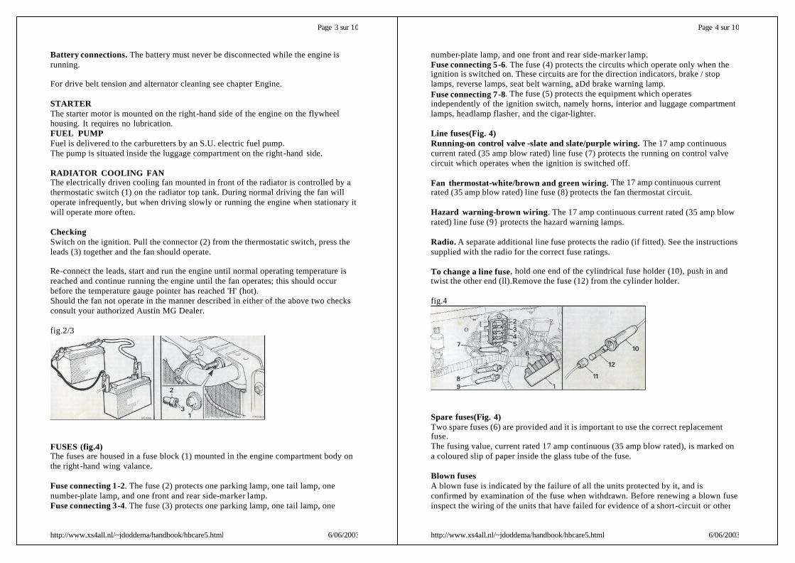
FUSES (fig.4)The fuses are housed in a fuse block (1) mounted in the engine compartment body onthe right-hand wing valance.
Fuse connecting 1-2. The fuse (2) protects one parking lamp, one tail lamp, onenumber-plate lamp, and one front and rear side-marker lamp.Fuse connecting 3-4. The fuse (3) protects one parking lamp, one tail lamp, one
Page 3 sur 10
6/06/2003http://www.xs4all.nl/~jdoddema/handbook/hbcare5.html
number-plate lamp, and one front and rear side-marker lamp.Fuse connecting 5-6. The fuse (4) protects the circuits which operate only when theignition is switched on. These circuits are for the direction indicators, brake / stoplamps, reverse lamps, seat belt warning, aDd brake warning lamp.Fuse connecting 7-8. The fuse (5) protects the equipment which operatesindependently of the ignition switch, namely horns, interior and luggage compartmentlamps, headlamp flasher, and the cigar-lighter.
Line fuses(Fig. 4)Running-on control valve -slate and slate/purple wiring. The 17 amp continuouscurrent rated (35 amp blow rated) line fuse (7) protects the running on control valvecircuit which operates when the ignition is switched off.
Fan thermostat-white/brown and green wiring. The 17 amp continuous currentrated (35 amp blow rated) line fuse (8) protects the fan thermostat circuit.
Hazard warning-brown wiring. The 17 amp continuous current rated (35 amp blowrated) line fuse (9} protects the hazard warning lamps.
Radio. A separate additional line fuse protects the radio (if fitted). See the instructionssupplied with the radio for the correct fuse ratings.
To change a line fuse, hold one end of the cylindrical fuse holder (10), push in andtwist the other end (ll).Remove the fuse (12) from the cylinder holder.
fig.4
Spare fuses(Fig. 4)Two spare fuses (6) are provided and it is important to use the correct replacementfuse.The fusing value, current rated 17 amp continuous (35 amp blow rated), is marked ona coloured slip of paper inside the glass tube of the fuse.
Blown fusesA blown fuse is indicated by the failure of all the units protected by it, and isconfirmed by examination of the fuse when withdrawn. Before renewing a blown fuseinspect the wiring of the units that have failed for evidence of a short -circuit or other
Page 4 sur 10
6/06/2003http://www.xs4all.nl/~jdoddema/handbook/hbcare5.html
fault.
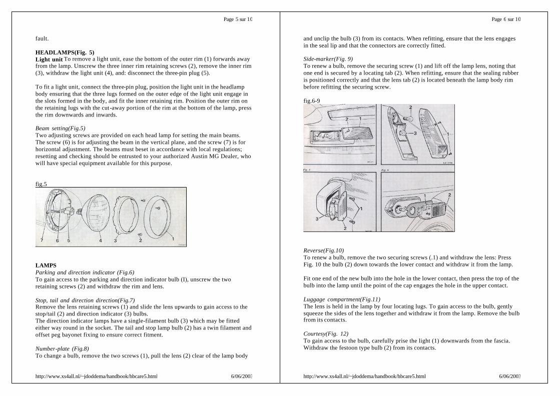
HEADLAMPS(Fig. 5)Light unit To remove a light unit, ease the bottom of the outer rim (1) forwards awayfrom the lamp. Unscrew the three inner rim retaining screws (2), remove the inner rim(3), withdraw the light unit (4), and: disconnect the three-pin plug (5).
To fit a light unit, connect the three-pin plug, position the light unit in the headlampbody ensuring that the three lugs formed on the outer edge of the light unit engage inthe slots formed in the body, and fit the inner retaining rim. Position the outer rim onthe retaining lugs with the cut-away portion of the rim at the bottom of the lamp, pressthe rim downwards and inwards.
Beam setting(Fig.5)Two adjusting screws are provided on each head lamp for setting the main beams.The screw (6) is for adjusting the beam in the vertical plane, and the screw (7) is forhorizontal adjustment. The beams must beset in accordance with local regulations;resetting and checking should be entrusted to your authorized Austin MG Dealer, whowill have special equipment available for this purpose.
fig.5
LAMPSParking and direction indicator (Fig.6)To gain access to the parking and direction indicator bulb (I), unscrew the tworetaining screws (2) and withdraw the rim and lens.
Stop, tail and direction direction(Fig.7)Remove the lens retaining screws (1) and slide the lens upwards to gain access to thestop/tail (2) and direction indicator (3) bulbs.The direction indicator lamps have a single-filament bulb (3) which may be fittedeither way round in the socket. The tail and stop lamp bulb (2) has a twin filament andoffset peg bayonet fixing to ensure correct fitment.
Number-plate (Fig.8)To change a bulb, remove the two screws (1), pull the lens (2) clear of the lamp body
Page 5 sur 10
6/06/2003http://www.xs4all.nl/~jdoddema/handbook/hbcare5.html
and unclip the bulb (3) from its contacts. When refitting, ensure that the lens engagesin the seal lip and that the connectors are correctly fitted.
Side-marker(Fig. 9)To renew a bulb, remove the securing screw (1) and lift off the lamp lens, noting thatone end is secured by a locating tab (2). When refitting, ensure that the sealing rubberis positioned correctly and that the lens tab (2) is located beneath the lamp body rimbefore refitting the securing screw.
fig.6-9
Reverse(Fig.10)To renew a bulb, remove the two securing screws (.1) and withdraw the lens: PressFig. 10 the bulb (2) down towards the lower contact and withdraw it from the lamp.
Fit one end of the new bulb into the hole in the lower contact, then press the top of thebulb into the lamp until the point of the cap engages the hole in the upper contact.
Luggage compartment(Fig.11)The lens is held in the lamp by four locating lugs. To gain access to the bulb, gentlysqueeze the sides of the lens together and withdraw it from the lamp. Remove the bulbfrom its contacts.
Courtesy(Fig. 12)To gain access to the bulb, carefully prise the light (1) downwards from the fascia.Withdraw the festoon type bulb (2) from its contacts.
Page 6 sur 10
6/06/2003http://www.xs4all.nl/~jdoddema/handbook/hbcare5.html
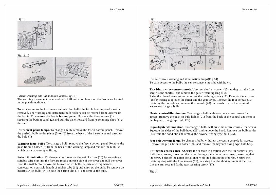
Fig.10
Fig.11/12
Fascia warning and illumination lamps(Fig.13)The warning instrument panel and switch illumination lamps on the fascia are locatedin the positions shown.
To gain access to the instrument and warning bulbs the fascia bottom panel must beremoved. The warning and instrument bulb holders can be reached from underneaththe fascia. To remove the fascia bottom panel. Unscrew the three screws (1)securing the bottom panel (2) and pull the panel forward from its retaining clips (3) atthe rear.
Instrument panel lamps. To change a bulb, remove the fascia bottom panel. Removethe push-fit bulb holder (4) or (5) or (6) from the back of the instrument and unscrewthe bulb (7).
Warning lamp bulbs. To change a bulb, remove the fascia bottom panel. Remove thepush-fit bulb holder (8) from the back of the warning lamp and remove the bulb (9)which has a bayonet type fitting.
Switch illumination. To change a bulb remove the switch cover (10) by engaging asuitable wire clip into the forward recess on each side of the cover and pull the coverfrom the switch. To remove the blower switch bulb (12) use a wiring harnessconnector or a suitable length of rubber tube (11) and unscrew the bulb. To remove thehazard switch bulb (14) release the spring clip (13) and remove the bulb.
Page 7 sur 10
6/06/2003http://www.xs4all.nl/~jdoddema/handbook/hbcare5.html
Fig.13
Centre console warning and illumination lamps(Fig.14)To gain access to the bulbs the centre console must be withdrawn.
To withdraw the centre console. Unscrew the four screws (15), noting that the frontscrew is the shortest, and remove the gaiter retaining ring (16).Raise the hinged arm-rest and unscrew the retaining screw (17). Remove the arm-rest(18) by easing it up over the gaiter and the gear lever. Remove the four screws (19)retaining the console and remove the console (20) rearwards to give the requiredaccess to change a bulb.
Heater control illumination. To change a bulb withdraw the centre console foraccess. Remove the push-fit bulb holder (21) from the back of the control and removethe bayonet fixing type bulb (22).
Cigar-lighter illumination. To change a bulb, withdraw the centre console for access.Squeeze the sides of the bulb hood (23) and remove the hood. Remove the bulb holder(24) from the hood clip and remove the bayonet fixing type bulb (25).
Seat belt warning lamp. To change a bulb, withdraw the centre console for access.Remove the push-fit bulb holder (26) and remove the bayonet fixing type bulb.(27).
Fitting the centre console.Secure the console in position with the four screws (19).Refit the arm-rest, threading the gaiter through the hole in the arm-rest, ensuring thatthe screw holes of the gaiter are aligned with the holes in the arm-rest. Secure theretaining ring with the four screws (15), ensuring that the short screw is at the front.Lift the arm-rest and fit the rear securing screw (17).
Fig.14
Page 8 sur 10
6/06/2003http://www.xs4all.nl/~jdoddema/handbook/hbcare5.html
Replacement bulbs
Part No.Sidelamp (with flasher) GLB 380Stop/tail. GLB 380Reverse. BFS 273Number-plate lamp. GLB 254Direction indicator. GLB 382Side marker lamp, front and rear. BFS 222Luggage compartment lamp. GLB 254Courtesy lamp. GLB 272Ignition warning. GLB 281Mainbeam GLB281Direction indicator warning lamp GLB 281Brake warning lamp. GLB 281Hazard warning lamp. GLB 281Seat belt warning lamp. GLB 281Switch illumination. GLB 284Heater rotary control illumination. GLB i81Panel illumination lamp. GLB 987Cigar-Iighter illumination. GBS 643
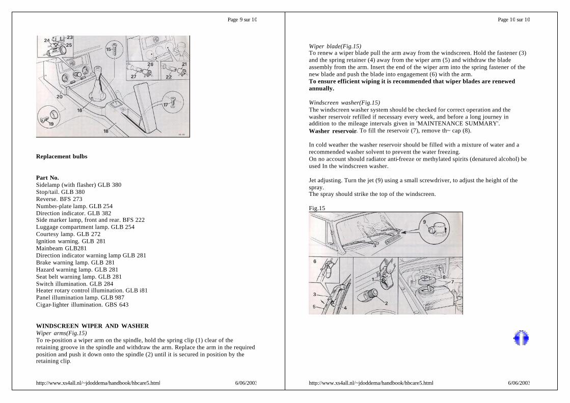
WINDSCREEN WIPER AND WASHERWiper arms(Fig.15)To re-position a wiper arm on the spindle, hold the spring clip (1) clear of theretaining groove in the spindle and withdraw the arm. Replace the arm in the requiredposition and push it down onto the spindle (2) until it is secured in position by theretaining clip.
Page 9 sur 10
6/06/2003http://www.xs4all.nl/~jdoddema/handbook/hbcare5.html
Wiper blade(Fig.15)To renew a wiper blade pull the arm away from the windscreen. Hold the fastener (3)and the spring retainer (4) away from the wiper arm (5) and withdraw the bladeassembly from the arm. Insert the end of the wiper arm into the spring fastener of thenew blade and push the blade into engagement (6) with the arm.To ensure efficient wiping it is recommended that wiper blades are renewedannually.
Windscreen washer(Fig.15)The windscreen washer system should be checked for correct operation and thewasher reservoir refilled if necessary every week, and before a long journey inaddition to the mileage intervals given in 'MAINTENANCE SUMMARY'.Washer reservoir. To fill the reservoir (7), remove th~ cap (8).
In cold weather the washer reservoir should be filled with a mixture of water and arecommended washer solvent to prevent the water freezing.On no account should radiator anti-freeze or methylated spirits (denatured alcohol) beused In the windscreen washer.
Jet adjusting. Turn the jet (9) using a small screwdriver, to adjust the height of thespray.The spray should strike the top of the windscreen.
Fig.15
Page 10 sur 10
6/06/2003http://www.xs4all.nl/~jdoddema/handbook/hbcare5.html
Ignition timingThe ignition timing is set dynamically to give optimum engine performance withefficient emmision control. Electronic test equipment must be used to checj theignition timing setting and the automatic advance (see 'GENERAL DATA'). Checkingand adjustment to the ignition timing setting should be carried out by your authorizedAustin MG Dealer.
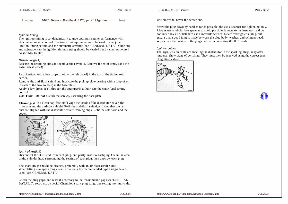
Distributor(fig1)Release the retaining clips and remove the cover(1). Remove the rotor arm(2) and theanti-flash shield(3).
Lubrication. Add a few drops of oil to the felt pad(4) in the top of the timing rotorcarrier.Remove the anti-flash shield and lubricate the pick-up plate bearing with a drop of oilin each of the two holes(5) in the base plate.Apply a few drops of oil through the aperture(6) to lubricate the centrifugal timingcontrol.CAUTION: Do not disturb the screw(7) securing the base plate.
Cleaning. With a clean nap-free cloth wipe the inside of the distributor cover, therotor arm and the anti-flash shield. Refit the anti-flash shield, ensuring that the cut-outs are aligned with the distributor cover retaining clips. Refit the rotor arm and thecover.
Spark plugs(fig2)Disconnect the H.T. lead from each plug, and partly unscrew eachplug. Clean the areaof the cylinder head surrounding the seating of each plug, then unscrew each plug.
The spark plugs should be cleaned, preferably with an air-blast service unit.When fitting new spark plugs ensure that only the recommended type and grade areused (see 'GENERAL DATA').
Check the plug gaps, and reset if necessary to the recommende gap (see 'GENERALDATA'). To reset, use a special Champion spark plug gauge ans setting tool; move the
Previous MGB Driver's Handbook 1976, part 12.Ignition Next
Page 1 sur 2Hi, I'm B, ... MG-B - hbcare6
6/06/2003http://www.xs4all.nl/~jdoddema/handbook/hbcare6.html
side electrode, never the center one.
Screw the plug down by hand as far as possible, the use a spanner for tightening only.Always use a tubular box spanner to avoid possible damage to the insulator, and donot under any circumstances use a moveble wrench. Never overtighten a plug, butensure that a good joint is made between the plug body, washer, and cylinder head.Wipe clean the outside of the plugs before reconnecting the H.T. leads.
Ignition cablesThe high-tension cables connecting the distributor to the sparking plugs, may afterlong use, show signs of perishing. They must then be renewed using the correct typeof ignition cable.
Page 2 sur 2Hi, I'm B, ... MG-B - hbcare6
6/06/2003http://www.xs4all.nl/~jdoddema/handbook/hbcare6.html

CheckingThe level of the oil in the engine sump is indicated by the dipstick(1) on the right-handside of the engine. Maintain the level between the MIN and MAX mark on thedipstick and never allow it to fall below the MIN mark.
The filler(2) is on the forward end of the rocker cover and is provided with a quick-action cap.
Ensure that the dipstick is correctly refitted.
The oil level should allways be checked before a long journey.
DrainingTo drain the engine oil, remove the drain plug(3) located on the right-hand side at therear of the sump. This operation should be carried out while the engine is warm.Cleaning the drain plug; check that its copper sealing washer is in a satisfactorycondition, and refit.
FillingFill the engine with the correct quantity(see GENERAL DATA) of a recommendedoil. Run the engine for a short while then allow it to stand for a few minutes beforechecking the level with the dipstick.
Oil filter changingThe oil filter is a disposable cartridge type
To renew, unscrew the cartridge(1) from the filter head(2) and discard the cartridge.
Previous MGB Driver's Handbook 1976, part 13.Engine Next
Page 1 sur 3Hi, I'm B, ... MG-B - hbcare7
6/06/2003http://www.xs4all.nl/~jdoddema/handbook/hbcare7.html
NOTE: if difficulty in unscrewing the cartridge is experienced, consult yourauthorized Austin MG Dealer.
Smear the new seal(3) with engine oil and fit it into its groove in the new cartridge,Srew the cartridge to the filter head using hand force only.
Refill the engine with the correct quantity of a recommended lubricant, start theengine and check for oil leakage.
Drive belt.AlternatorTension. When correctly tensioned, a total deflection of ½ inch under moderate handpressure should be possible at the midway point of the longest belt run between thepulleys.
Adjusting. To adjust the belt tension, slacken the securing bolts(1) and adjusting linknuts(2), and move the alternator to the required position. Apply any leveragenecessary to the alternator end bracket(3) only and not to any other part; to avoiddamaging the drive-end bracket the leader should preferably be a wood or soft metal.Tighten the bolts and re-check the belt tension.DO NOT OVERTIGHTEN as this will impose an excess loading on the drivebearings.
Cleaning. Keep the slots in the plastic end-cover(4) clean.
Valve rocker clearanceCheckingDisconnect the purge pipe(1) from the rocker cover. Unscrew the nut and remove thevapour pipe(2), and disconnect the lead(3) from the induction heater.Remove the rocker cover(4) and insert a 0-013 inch feeler gauge(5) between the valverocker arms and the valve stem. The gauge should be sliding fit, when the engine iswarm.Check each clearance in the following order:Check No.1 valve with No.8 fully open. Check No.8 valve with No.1 fully open.Check No.3 valve with No.6 fully open. Check No.6 valve with No.3 fully open.Check No.5 valve with No.4 fully open. Check No.4 valve with No.5 fully open.Check No.2 valve with No.7 fully open. Check No.7 valve with No.2 fully open.
Page 2 sur 3Hi, I'm B, ... MG-B - hbcare7
6/06/2003http://www.xs4all.nl/~jdoddema/handbook/hbcare7.html

AdjustingSlacken the adjusting screw locknut(6) on the opposite end of the rocker arm androtate the screw(7) clockwise to reduce the clearance or anti-clockwise to increase it.Re-tighten the locknut when the clearance is correct, holding the screw againstrotation with a screwdriver.
CleaningClean the rocker cover sealing face. Examine the orifice(8) of the restrictor forobstruction.Clean any dirt or deposit from the restrictor orifice, using a length of soft wire.
RefittingCheck the rocker cover gasket(9) for damage, fit a new gasket if necessary.Refit the cover, the vapour pipe, and connect the purge pipe. Connect the lead to theinduction heater. Check that the oil filler cap(10) seals correctly; renew it if necessary.
Page 3 sur 3Hi, I'm B, ... MG-B - hbcare7
6/06/2003http://www.xs4all.nl/~jdoddema/handbook/hbcare7.html
Air CleanerThe element of the air cleaner must be renewed every 12.500 miles; more frequentchanges may be necessary in dusty operating conditions.
Element changingUnscrew the wing nut(1), pivot the end cover away from the engine to release the airtemperature control valve from the hot air hose(2), and remove the end cover(3).Withdraw the element(4) and discard it.Thoroughly clean the air cleaner and the casing(5). Fit a new element. Locate the endcover in position, ensuring that the lip(6) supports the inside of the filter element.Connect the air temperature control valve to the hot air hose, fit and tighten the wingnut.
Air intake temperature controlThe temperature of the air entering the carburetter is controlled by a valve fitted to theintake of the air cleaner. The control valve(7) should be inspected for condition andoperation by your authorized Austin MG Dealer.
Fig.1
Carburetter
Air pollution controlThe carburetter incorporates featueres which assist in reducing exhaust emissions.Maladjustment or the fitting of parts not to be required specification may render thesefeatures ineffective.
Carburetter damperChecking the oil level. Unscrew the damper cap(4) from the carburetter top cover.Carefully raise the damper to the top of its travel. Lower the damper back into thehollow piston rod. If the oil level in the hollow piston rod is correct, resistance shouldbe felt when there is a gap of approx. ¼ inch. (A) between the cap and the carburettertop cover. Top up if necessary. Screw the damper cap firmly to the carburetter top
Previous MGB Driver's Handbook 1976, part 14.Fuel System Next
Page 1 sur 2
6/06/2003http://www.xs4all.nl/~jdoddema/handbook/hbcare9.html
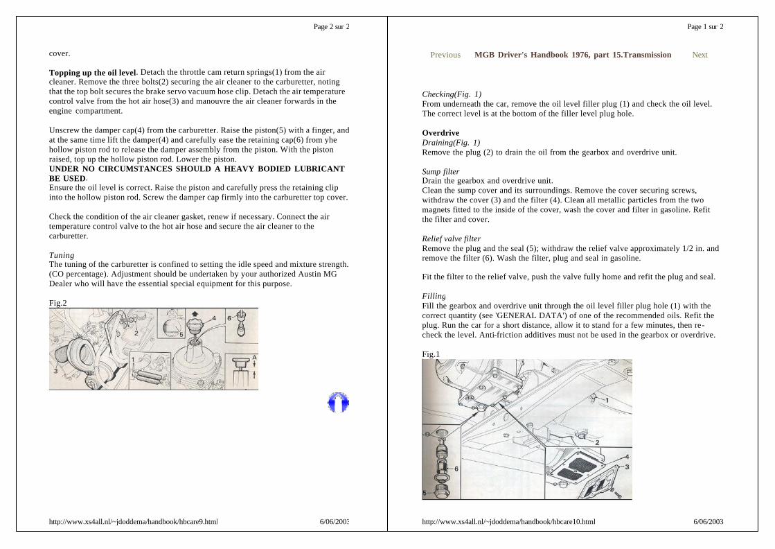
cover.
Topping up the oil level. Detach the throttle cam return springs(1) from the aircleaner. Remove the three bolts(2) securing the air cleaner to the carburetter, notingthat the top bolt secures the brake servo vacuum hose clip. Detach the air temperaturecontrol valve from the hot air hose(3) and manouvre the air cleaner forwards in theengine compartment.
Unscrew the damper cap(4) from the carburetter. Raise the piston(5) with a finger, andat the same time lift the damper(4) and carefully ease the retaining cap(6) from yhehollow piston rod to release the damper assembly from the piston. With the pistonraised, top up the hollow piston rod. Lower the piston.UNDER NO CIRCUMSTANCES SHOULD A HEAVY BODIED LUBRICANTBE USED.Ensure the oil level is correct. Raise the piston and carefully press the retaining clipinto the hollow piston rod. Screw the damper cap firmly into the carburetter top cover.
Check the condition of the air cleaner gasket, renew if necessary. Connect the airtemperature control valve to the hot air hose and secure the air cleaner to thecarburetter.
TuningThe tuning of the carburetter is confined to setting the idle speed and mixture strength.(CO percentage). Adjustment should be undertaken by your authorized Austin MGDealer who will have the essential special equipment for this purpose.
Fig.2
Page 2 sur 2
6/06/2003http://www.xs4all.nl/~jdoddema/handbook/hbcare9.html
Checking(Fig. 1)From underneath the car, remove the oil level filler plug (1) and check the oil level.The correct level is at the bottom of the filler level plug hole.
OverdriveDraining(Fig. 1)Remove the plug (2) to drain the oil from the gearbox and overdrive unit.
Sump filterDrain the gearbox and overdrive unit.Clean the sump cover and its surroundings. Remove the cover securing screws,withdraw the cover (3) and the filter (4). Clean all metallic particles from the twomagnets fitted to the inside of the cover, wash the cover and filter in gasoline. Refitthe filter and cover.
Relief valve filterRemove the plug and the seal (5); withdraw the relief valve approximately 1/2 in. andremove the filter (6). Wash the filter, plug and seal in gasoline.
Fit the filter to the relief valve, push the valve fully home and refit the plug and seal.
FillingFill the gearbox and overdrive unit through the oil level filler plug hole (1) with thecorrect quantity (see 'GENERAL DATA') of one of the recommended oils. Refit theplug. Run the car for a short distance, allow it to stand for a few minutes, then re-check the level. Anti-friction additives must not be used in the gearbox or overdrive.
Fig.1
Previous MGB Driver's Handbook 1976, part 15.Transmission Next
Page 1 sur 2
6/06/2003http://www.xs4all.nl/~jdoddema/handbook/hbcare10.html
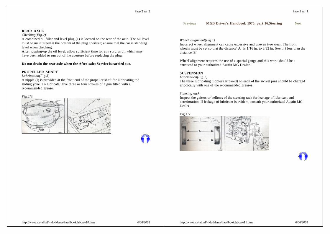
REAR AXLEChecking(Fig.2)A combined oil filler and level plug (1) is located on the rear of the axle. The oil levelmust be maintained at the bottom of the plug aperture; ensure that the car is standinglevel when checking.After topping-up the oil level, allow sufficient time for any surplus oil which mayhave been added to run out of the aperture before replacing the plug.
Do not drain the rear axle when the After-sales Service is carried out.
PROPELLER SHAFTLubrication(Fig.3)A nipple (I) is provided at the front end of the propeller shaft for lubricating thesliding yoke. To lubricate, give three or four strokes of a gun filled with arecommended grease.
Fig.2/3
Page 2 sur 2
6/06/2003http://www.xs4all.nl/~jdoddema/handbook/hbcare10.html
Wheel alignment(Fig.1)Incorrect wheel alignment can cause excessive and uneven tyre wear. The frontwheels must be set so that the distance' A ' is 1/16 in. to 3/32 in. (toe in} less than thedistance 'B'.
Wheel alignment requires the use of a special gauge and this work should be :entrusted to your authorized Austin MG Dealer.
SUSPENSIONLubrication(Fig.2)The three lubricating nipples (arrowed) on each of the swivel pins should be chargederiodically with one of the recommended greases.
Steering rackInspect the gaiters or bellows of the steering rack for leakage of lubricant anddeterioration. If leakage of lubricant is evident, consult your authorized Austin MGDealer.
Fig.1/2
Previous MGB Driver's Handbook 1976, part 16.Steering Next
Page 1 sur 1
6/06/2003http://www.xs4all.nl/~jdoddema/handbook/hbcare11.html
During running-in from new certain adjustments vary from the specification figuresdetailed.They will be set to specification by your authorized Austin MG Dealer at the After-Sales Service and should thereafter be maintained throughout the car's life.
Engine
Previous MGB Driver's Handbook 1976, part 17.General data Next
Type 18V 883AE/18V 890AE (Standard)18V 884AE/18V 891AE (Overdrive)
Bore 80.3 mmStroke 88.9 mmCylinders 4Compression ratio 8:1Capacity 1798ccFiring order 1,3,4,2Valve rocker clearance-set warn 0.33 mm
Oil pressure: IdlingOil pressure: Normal
0.17 to 1.7 kgf/cm23.5 to 5.6 kgf/cm2
Idle speed 850 rev/min
IgnitionStroboscopic ignitiontiming 10° B.T.D.C. at 1500 rev/min
Timing marks Notch on crankshaft pulley, pointers ontiming chain cover
Spark plugs Champion N-9YPlug gap 0.90 mmFuel systemCarburetter Zenith Stromberg type 175 CD5TFuel pump S.U. type AUF 300 electric
Gearbox and OverdriveOverdrive ratio 0'82 : 1Overall ratios:FirstSecondThirdFourthReverse
13.03 : 18.47 : 15.40 : 1(overdrive 4.43 : 1)3.909 : 1 (overdrive 3.20 : 1)12.098 : 1
Top gear speed per 1000
Page 1 sur 3
6/06/2003http://www.xs4all.nl/~jdoddema/handbook/gd.html
Tyre pressures (in bars)
It is recommended that for sustained speeds at near maximum the above tyrepressures are increased by 0.32 bars.
rev/min:StandardOverdrive
18 m.p.h. (29 km/h)22 m.p.h. (35 km/h)
CapacitiesFuel tank 45.4 litresCooling system 6.6 litresCooling system withheater 6.8 litres
Engine sump 3 litresEngine sump with filterchange 3.4 litres
Gearbox 2.84 litresGearbox with overdrive 3.4 litresRear axle 0.85 litreDimensionsLength 4 mWidth 152.3cmHeight, hood erected 129.2 cmGround clearance(minimum) 106 mm
Track:Pressed spoked wheel :Wire wheel :
Front 124.7 / Rear 126.4 cmFront 124.4 / Rear 125 cm
Wheelbase 231.5 cmTurning circle 9.75 mToe in 1.5 to 2.3 mm
Wheels and tyresWheel size:Pressed spokedWire
5J FH x 144 1/2J x 14 (60-spoke)
Tyres: 165SR-14 Radial-ply
Condition Front RearNormal car weight 1.45 1.66Gross car weight andsustained speed 1.45 1.79
Page 2 sur 3
6/06/2003http://www.xs4all.nl/~jdoddema/handbook/gd.html
Loading Totalweight
Kerbside ( including a full fuel tank and all optionalextras ) 1097kg
Normal ( including driver and passenger and full fueltank ) 1234kg
Gross (Maximum weight condition ) 1287kgRecommended towbar hitch load 45kg
Page 3 sur 3
6/06/2003http://www.xs4all.nl/~jdoddema/handbook/gd.html
The following items should be checked weekly by the driver :Engine oil levelBrake fluid levelRadiator coolant levelBattery electrolyte levelWindshield washer reservoir fluid levelAll tyre pressuresAll lights for operationHorn operationWindshield wipers operation
MAINTENANCE INTERVALS
NOTE: The service intervals are based on an annual mileage of approximately 12,500miles. Should the vehicle complete substantially less miles than this per annum, it isrecommended that a 'C' service is completed at six-month intervals, and a 'D' serviceat twelve-month intervals.
'A' SERVICE
LubricationLubricate all grease points (excluding hubs)Renew engine oilCheck/top up brake fluidreservoirCheck/top up clutch fluid reservoirCheck/top up battery electrolyteCheck/top up cooling systemCheck/top up rear axleDrain gearbox, refill with new oil (non-overdrive)Drain gearbox and overdrive, clean filters and refill with new oilCheck/top up screen washer reservoirLubricate distributorLubricate accelerator control linkage and pedal pivot; check operationLubricate all locks and hinges (not steering lock ).
Previous MGB Driver's Handbook 1976, part 18.Maintenance Next
Service Mileage x 1000 Monthly intervalsABCDE
13, 9, 16, 22, 28, 34, 41, 476, 19, 31, 4412.5, 37.525, 50
After sales service361224
Page 1 sur 8
6/06/2003http://www.xs4all.nl/~jdoddema/handbook/ms.html
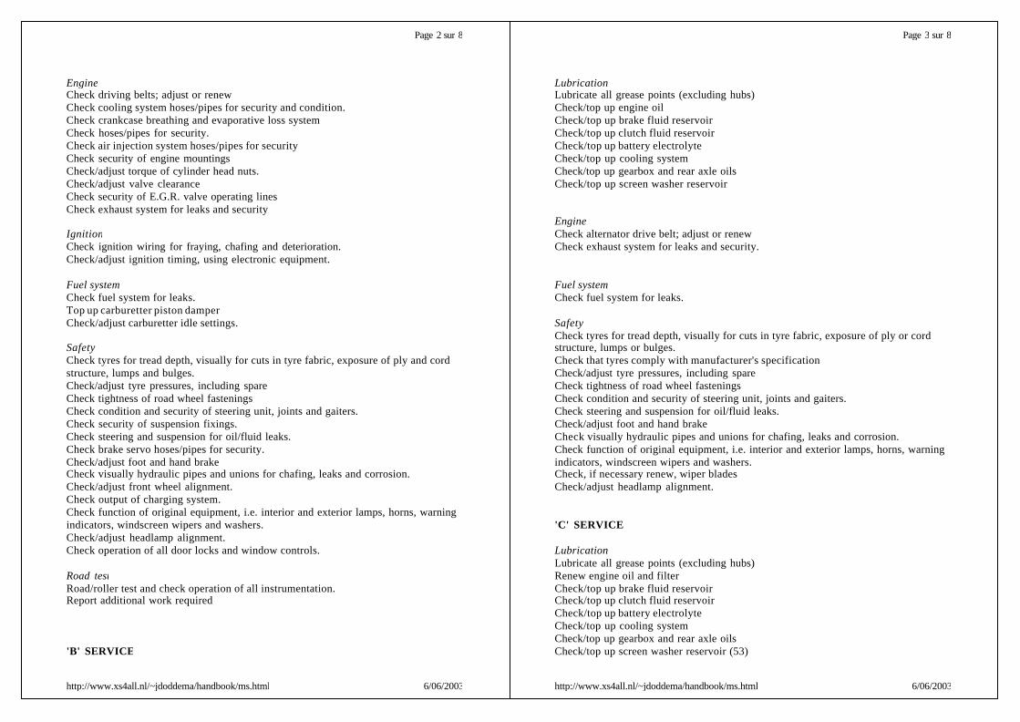
EngineCheck driving belts; adjust or renewCheck cooling system hoses/pipes for security and condition.Check crankcase breathing and evaporative loss systemCheck hoses/pipes for security.Check air injection system hoses/pipes for securityCheck security of engine mountingsCheck/adjust torque of cylinder head nuts.Check/adjust valve clearanceCheck security of E.G.R. valve operating linesCheck exhaust system for leaks and security
IgnitionCheck ignition wiring for fraying, chafing and deterioration.Check/adjust ignition timing, using electronic equipment.
Fuel systemCheck fuel system for leaks.Top up carburetter piston damperCheck/adjust carburetter idle settings.
SafetyCheck tyres for tread depth, visually for cuts in tyre fabric, exposure of ply and cordstructure, lumps and bulges.Check/adjust tyre pressures, including spareCheck tightness of road wheel fasteningsCheck condition and security of steering unit, joints and gaiters.Check security of suspension fixings.Check steering and suspension for oil/fluid leaks.Check brake servo hoses/pipes for security.Check/adjust foot and hand brakeCheck visually hydraulic pipes and unions for chafing, leaks and corrosion.Check/adjust front wheel alignment.Check output of charging system.Check function of original equipment, i.e. interior and exterior lamps, horns, warningindicators, windscreen wipers and washers.Check/adjust headlamp alignment.Check operation of all door locks and window controls.
Road testRoad/roller test and check operation of all instrumentation.Report additional work required
'B' SERVICE
Page 2 sur 8
6/06/2003http://www.xs4all.nl/~jdoddema/handbook/ms.html
LubricationLubricate all grease points (excluding hubs)Check/top up engine oilCheck/top up brake fluid reservoirCheck/top up clutch fluid reservoirCheck/top up battery electrolyteCheck/top up cooling systemCheck/top up gearbox and rear axle oilsCheck/top up screen washer reservoir
EngineCheck alternator drive belt; adjust or renewCheck exhaust system for leaks and security.
Fuel systemCheck fuel system for leaks.
SafetyCheck tyres for tread depth, visually for cuts in tyre fabric, exposure of ply or cordstructure, lumps or bulges.Check that tyres comply with manufacturer's specificationCheck/adjust tyre pressures, including spareCheck tightness of road wheel fasteningsCheck condition and security of steering unit, joints and gaiters.Check steering and suspension for oil/fluid leaks.Check/adjust foot and hand brakeCheck visually hydraulic pipes and unions for chafing, leaks and corrosion.Check function of original equipment, i.e. interior and exterior lamps, horns, warningindicators, windscreen wipers and washers.Check, if necessary renew, wiper bladesCheck/adjust headlamp alignment.
'C' SERVICE
LubricationLubricate all grease points (excluding hubs)Renew engine oil and filterCheck/top up brake fluid reservoirCheck/top up clutch fluid reservoirCheck/top up battery electrolyteCheck/top up cooling systemCheck/top up gearbox and rear axle oilsCheck/top up screen washer reservoir (53)
Page 3 sur 8
6/06/2003http://www.xs4all.nl/~jdoddema/handbook/ms.html

Lubricate distributorLubricate accelerator control linkage and pedal pivot; check operationLubricate all locks and hinges (not steering lock).
EngineCheck alternator drive belt; adjust or renewCheck cooling system hoses/pipes for security and condition.Check exhaust system for leaks and security.
IgnitionClean spark plugs
Fuel systemCheck fuel system for leaks.
SafetyCheck tyres for tread depth, visually for cuts in tyre fabric, exposure of ply or cordstructure, lumps and bulges.Check that tyres comply with manufacturer's specificationCheck/adjust tyre pressures, including spareCheck tightness of road wheel fasteningsCheck condition and security of steering unit, joints and gaiters.Check security of suspension fixings.Check steering and suspension for oil/fluid leaks.Inspect brake pads for wear, discs for conditionCheck brake servo hoses/pipe for security.Check/adjust foot and hand brakeCheck visually hydraulic pipes and unions for chafing, leaks and corrosionCheck/adjust front wheel alignmentCheck output of charging system.Check function of original equipment, i.e. interior and exterior lamps, horns, warningindicators windscreen wipers and washers.Check, if necessary renew, wiper bladesCheck/adjust headlamp alignment.Check condition and security of seats, seat belts and seat belt warning system
Road testRoad/roller test and check operation of all instrumentation.Report additional work required
BrakesIt is further recommended that at 19,000 miles (or 18 months) the brake fluid isrenewed.This additional work should be carried out by your authorized Austin MG Dealer.
'D' SERVICE
Page 4 sur 8
6/06/2003http://www.xs4all.nl/~jdoddema/handbook/ms.html
LubricationLubricate all grease points (excluding hubs)Renew engine oil and filterCheck/top up brake fluid reservoirCheck/top up clutch fluid reservoirCheck/top up battery electrolyteCheck/top up cooling systemCheck/top up gearbox and rear axle oilsCheck/top up screen washer reservoirLubricate distributorLubricate accelerator control linkage and pedal pivot, check operationLubricate all locks and hinges (not steering lock )
EngineCheck driving belts, adjust or renewCheck cooling system hoses/pipes for security and condition.Renew carburetter air cleaner elementRenew air pump air filterCheck gulp valve and check valve operation.Check air injection system hoses/pipes for securityCheck air intake temperature control systemCheck crankcase breathing and evaporative loss systemsCheck hoses/pipes and restrictors for blockage, security and conditionCheck/adjust valve clearancesCheck exhaust system for leaks and security
IgnitionCheck ignition wiring for fraying, chafing and deteriorationRenew spark plugsClean distributor cap; check for cracks and trackingCheck/adjust ignition timing, using electronic equipment
Fuel systemRenew fuel line filterCheck fuel system for leaksTop up carburetter piston damperCheck/adjust carburetter idle settingsCheck condition of fuel filler cap seal
SafetyCheck tyres for tread depth, visually for cuts in tyre fabric, exposure of ply or cordstructure, Jumps and bulges.Check that tyres comply with manufacturers' specificationCheck/adjust tyre pressures, including spareCheck tightness of road wheel fasteningsCheck condition and security of steering unit, joints and gaiters
Page 5 sur 8
6/06/2003http://www.xs4all.nl/~jdoddema/handbook/ms.html
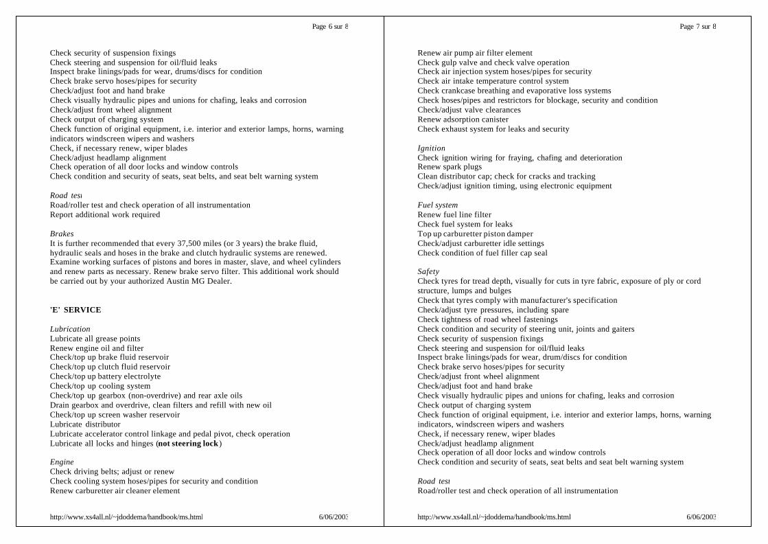
Check security of suspension fixingsCheck steering and suspension for oil/fluid leaksInspect brake linings/pads for wear, drums/discs for conditionCheck brake servo hoses/pipes for securityCheck/adjust foot and hand brakeCheck visually hydraulic pipes and unions for chafing, leaks and corrosionCheck/adjust front wheel alignmentCheck output of charging systemCheck function of original equipment, i.e. interior and exterior lamps, horns, warningindicators windscreen wipers and washersCheck, if necessary renew, wiper bladesCheck/adjust headlamp alignmentCheck operation of all door locks and window controlsCheck condition and security of seats, seat belts, and seat belt warning system
Road testRoad/roller test and check operation of all instrumentationReport additional work required
BrakesIt is further recommended that every 37,500 miles (or 3 years) the brake fluid,hydraulic seals and hoses in the brake and clutch hydraulic systems are renewed.Examine working surfaces of pistons and bores in master, slave, and wheel cylindersand renew parts as necessary. Renew brake servo filter. This additional work shouldbe carried out by your authorized Austin MG Dealer.
'E' SERVICE
LubricationLubricate all grease pointsRenew engine oil and filterCheck/top up brake fluid reservoirCheck/top up clutch fluid reservoirCheck/top up battery electrolyteCheck/top up cooling systemCheck/top up gearbox (non-overdrive) and rear axle oilsDrain gearbox and overdrive, clean filters and refill with new oilCheck/top up screen washer reservoirLubricate distributorLubricate accelerator control linkage and pedal pivot, check operationLubricate all locks and hinges (not steering lock )
EngineCheck driving belts; adjust or renewCheck cooling system hoses/pipes for security and conditionRenew carburetter air cleaner element
Page 6 sur 8
6/06/2003http://www.xs4all.nl/~jdoddema/handbook/ms.html
Renew air pump air filter elementCheck gulp valve and check valve operationCheck air injection system hoses/pipes for securityCheck air intake temperature control systemCheck crankcase breathing and evaporative loss systemsCheck hoses/pipes and restrictors for blockage, security and conditionCheck/adjust valve clearancesRenew adsorption canisterCheck exhaust system for leaks and security
IgnitionCheck ignition wiring for fraying, chafing and deteriorationRenew spark plugsClean distributor cap; check for cracks and trackingCheck/adjust ignition timing, using electronic equipment
Fuel systemRenew fuel line filterCheck fuel system for leaksTop up carburetter piston damperCheck/adjust carburetter idle settingsCheck condition of fuel filler cap seal
SafetyCheck tyres for tread depth, visually for cuts in tyre fabric, exposure of ply or cordstructure, lumps and bulgesCheck that tyres comply with manufacturer's specificationCheck/adjust tyre pressures, including spareCheck tightness of road wheel fasteningsCheck condition and security of steering unit, joints and gaitersCheck security of suspension fixingsCheck steering and suspension for oil/fluid leaksInspect brake linings/pads for wear, drum/discs for conditionCheck brake servo hoses/pipes for securityCheck/adjust front wheel alignmentCheck/adjust foot and hand brakeCheck visually hydraulic pipes and unions for chafing, leaks and corrosionCheck output of charging systemCheck function of original equipment, i.e. interior and exterior lamps, horns, warningindicators, windscreen wipers and washersCheck, if necessary renew, wiper bladesCheck/adjust headlamp alignmentCheck operation of all door locks and window controlsCheck condition and security of seats, seat belts and seat belt warning system
Road testRoad/roller test and check operation of all instrumentation
Page 7 sur 8
6/06/2003http://www.xs4all.nl/~jdoddema/handbook/ms.html
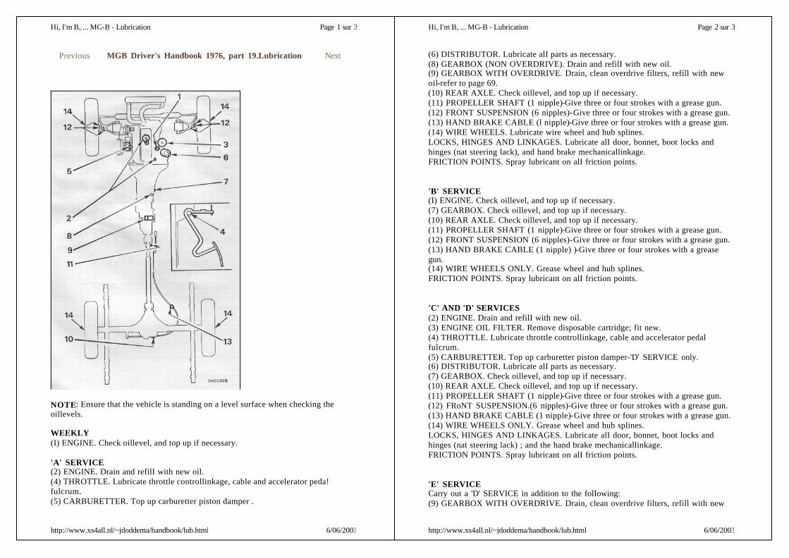
NOTE: Ensure that the vehicle is standing on a level surface when checking theoillevels.
WEEKLY(I) ENGINE. Check oillevel, and top up if necessary.
'A' SERVICE(2) ENGINE. Drain and refilI with new oil.(4) THROTTLE. Lubricate throttle controllinkage, cable and accelerator peda!fulcrum.(5) CARBURETTER. Top up carburetter piston damper .
Previous MGB Driver's Handbook 1976, part 19.Lubrication Next
Page 1 sur 3Hi, I'm B, ... MG-B - Lubrication
6/06/2003http://www.xs4all.nl/~jdoddema/handbook/lub.html
(6) DISTRIBUTOR. Lubricate alI parts as necessary.(8) GEARBOX (NON OVERDRIVE). Drain and refilI with new oil.(9) GEARBOX WITH OVERDRIVE. Drain, clean overdrive filters, refill with newoil-refer to page 69.(10) REAR AXLE. Check oillevel, and top up if necessary.(11) PROPELLER SHAFT (1 nipple)-Give three or four strokes with a grease gun.(12) FRONT SUSPENSION (6 nipples)-Give three or four strokes with a grease gun.(13) HAND BRAKE CABLE (l nipple)-Give three or four strokes with a grease gun.(14) WIRE WHEELS. Lubricate wire wheel and hub splines.LOCKS, HINGES AND LINKAGES. Lubricate alI door, bonnet, boot locks andhinges (nat steering lack), and hand brake mechanicallinkage.FRICTION POINTS. Spray lubricant on alI friction points.
'B' SERVICE(I) ENGlNE. Check oillevel, and top up if necessary.(7) GEARBOX. Check oillevel, and top up if necessary.(10) REAR AXLE. Check oillevel, and top up if necessary.(11) PROPELLER SHAFT (1 nipple)-Give three or four strokes with a grease gun.(12) FRONT SUSPENSION (6 nipples)-Give three or four strokes with a grease gun.(13) HAND BRAKE CABLE (1 nipple) )-Give three or four strokes with a greasegun.(14) WIRE WHEELS ONLY. Grease wheel and hub splines.FRICTION POINTS. Spray lubricant on alI friction points.
'C' AND 'D' SERVICES(2) ENGINE. Drain and refilI with new oil.(3) ENGINE OIL FILTER. Remove disposable cartridge; fit new.(4) THROTTLE. Lubricate throttle controllinkage, cable and accelerator pedalfulcrum.(5) CARBURETTER. Top up carburetter piston damper-'D' SERVICE only.(6) DISTRIBUTOR. Lubricate alI parts as necessary.(7) GEARBOX. Check oillevel, and top up if necessary.(10) REAR AXLE. Check oillevel, and top up if necessary.(11) PROPELLER SHAFT (1 nipple)-Give three or four strokes with a grease gun.(12) FRoNT SUSPENSION.(6 nipples)-Give three or four strokes with a grease gun.(13) HAND BRAKE CABLE (1 nipple)-Give three or four strokes with a grease gun.(14) WIRE WHEELS ONLY. Grease wheel and hub splines.LOCKS, HINGES AND LINKAGES. Lubricate alI door, bonnet, boot locks andhinges (nat steering lack) ; and the hand brake mechanicallinkage.FRICTION POINTS. Spray lubricant on alI friction points.
'E' SERVICECarry out a 'D' SERVICE in addition to the folIowing:(9) GEARBOX WITH OVERDRIVE. Drain, clean overdrive filters, refill with new
Page 2 sur 3Hi, I'm B, ... MG-B - Lubrication
6/06/2003http://www.xs4all.nl/~jdoddema/handbook/lub.html

Identification(fig.1)When communicating with your Distributor or Dealer always quote the car andengine numbers. When the communication concerns the transmission units or bodydetails it is necessary to quote also the transmission casing and body numbers.
(1) Car number. Stamped on a plate secured to the left -hand door post. and to a platesecured to the top of the fascia.(2) Engine number. Stamped on a plate secured to the right -hand side of the cylinderblock.(3) Gearbox number. Stamped on the right-hand side of the gearbox casing.(4) Overdrive unit number. Stamped on a plate secured to the underside of theoverdrive main casing.(5) Rear axle number. Stamped on the left -hand side of the rear axle tube near thespring seating.
Service parts
Genuine BRITISH LEYLAND and UNIPART parts are designed and tested foryour vehicle and have the full backing of the British Leyland Factory Warranty.Genuille British Leyland and UNIPART parts are supplied in cartons and packs.
British Leyland Motors Inc.600 Willow Tree Road, LeoniaNew Jersey 07605Telephone: (201) 461 !7300 Telex: 135491
Previous MGB Driver's Handbook 1976, part 20.Service part.1
Page 1 sur 1Hi, I'm B, ... MG-B - service
6/06/2003http://www.xs4all.nl/~jdoddema/handbook/service.html