part drawing and process sheet for design of toggle jack (pdf
TRANSCRIPT
ISSN: 2394-6881
International Journal of Engineering Technology and Management (IJETM)
Available Online at www.ijetm.org
Volume 2, Issue 3, May-June 2015, Page No. 25-33
Corresponding author: Pravin B. Adke
Pag
e25
Part Drawing and Process Sheet for Design of Toggle Jack
Pravin B. Adke1, Shrikant U. Gunjal
2, Gaurav D. Sonawane
3
1, 2, 3 Department of Mechanical Engineering, Sandip Foundation’s- SITRC, Mahiravani, Trimbak Road, Nashik, Maharashtra 422 213
Savitribai Phule Pune University (SPPU), Maharashtra, India.
[email protected], [email protected], [email protected]
ABSTRACT Design of any mechanical component is most important and at the same time one of the challenging task. Design engineer have to consider various factors while designing even a single component having simple geometrical attributes. Toggle jack consists of various parts and it requires special attention while designing every part of toggle jack. This paper describes the design considerations with respect to part drawing and process sheet. We have tabulated design of toggle jack parts including tool used and time required for process to carry out along with part drawing in process sheet.
Keywords: Design, Geometrical attributes, Toggle jack, Part drawing, Process sheet, Tool, Time required.
INTRODUCTION: There are many applications where we need to use Toggle jack. Proper Design fundamental defines the capability of every component, device or system in application. Design engineer need to go through all the adverse possibilities while designing the components and accordingly it is necessary to do safe design. In Toggle jack device we use a power screw mechanism and trolley mechanism. Power screw are used to convert rotary motion into translatory motion , for example in case of lead screw of a lathe machine, rotary motion available
but tool has to be advanced distance in direction of cut against the cutting resistance of a material. In case of screw small force applied in horizontal plane is used to raise or lower the large load [1]. Power also used in toggle jack, screw jack, vice, material testing machine etc. In a toggle jack it has an axial motion against resisting axial force while screw rotates in a stationary bearing. In screw jack, a screw rotates and moves axially against resisting force while nut is stationary.
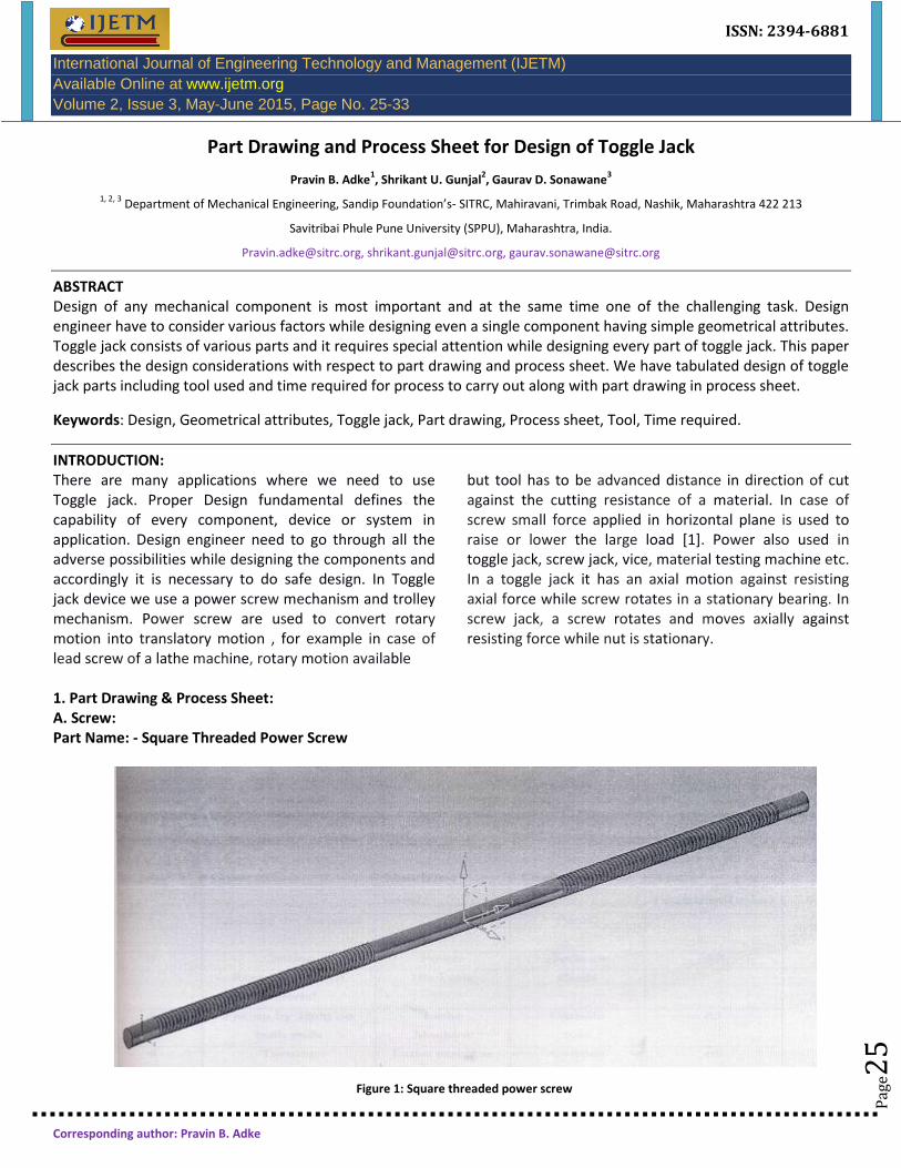
1. Part Drawing & Process Sheet: A. Screw: Part Name: - Square Threaded Power Screw
Figure 1: Square threaded power screw

Pravin B. Adke, et al. International Journal of Engineering Technology and Management (IJETM)
© 2015 IJETM. All Rights Reserved.
Pag
e26
P
age2
6
Pag
e26
P
age2
6
Pag
e26
P
age2
6
Pag
e26
P
age2
6
Pag
e26
P
age2
6
Pag
e26
P
age2
6
Pag
e26
P
age2
6
Pag
e26
P
age2
6
Pag
e26
P
age2
6
Pag
e26
P
age2
6
Pag
e26
Part No: - 1 Material: - EN 24 Quantity: - 1 Size: - Ǿ 25 mm Length: - 1105 mm
Table 1: Process Sheet
Sr. no. Operation Machine used Tool Time required(min)
1 Marking the material - Pencil 10
2 Cutting Power Hacksaw 30
Required size of Hacksaw Blade
material
3 Facing by Imm on Lathe Carbide 45
both ends Machine tool
4 Turning Lathe machine Carbide 60
Required size Tool
i.e. & 23mm.
5 Threading Lathe Threading tool 240
&23mm (6mm pitch at
length
350*2mm).
6 Finishing of non Smooth file 30
threaded pert
Total time 415min.
B. Slider Link:
Figure 2: Slider link

Pravin B. Adke, et al. International Journal of Engineering Technology and Management (IJETM)
© 2015 IJETM. All Rights Reserved.
Pag
e27
P
age2
7
Pag
e27
P
age2
7
Pag
e27
P
age2
7
Pag
e27
P
age2
7
Pag
e27
P
age2
7
Pag
e27
P
age2
7
Pag
e27
P
age2
7
Pag
e27
P
age2
7
Pag
e27
P
age2
7
Pag
e27
P
age2
7
Pag
e27
Part name:-Slider link Part no:-2 Material:-M.S. black Quantity:-8 Size:-400*35*8mm
Table 2: Process sheet
Sr. No. Operation Machine used Tool Time required
(min)
1 Cutting Of plate 400*35*8mm.
Gas cutting Gas cutter nozzle 70
2 Radius Grinding R17.5mm.
Bench grinder Grinding wheel 45
3 Drilling
Φ14mm. Bench drilling Drill <1> 14mm. 60
4 Finishing Portable
hand Hand grinder
disc Grinding wheel
50
Total time 225min.
C.H-Section:
Figure 3: H- Section
Part Name: - H – Section Part no:-3 Quantity:-2 Material:-M.S. black Size:-280*90* 15
Pravin B. Adke, et al. International Journal of Engineering Technology and Management (IJETM)
© 2015 IJETM. All Rights Reserved.
Pag
e28
P
age2
8
Pag
e28
P
age2
8
Pag
e28
P
age2
8
Pag
e28
P
age2
8
Pag
e28
P
age2
8
Pag
e28
P
age2
8
Pag
e28
P
age2
8
Pag
e28
P
age2
8
Pag
e28
P
age2
8
Pag
e28
P
age2
8
Pag
e28
Table 3:
Process sheet
Sr. no. I
Operation Machine
used Tools
Time required(min)
1 Cutting Bench saw - 90
2 Grinding Grinder Grinding
wheel 60
3 Drilling Drilling
Machine Drill tool 75
4 Boring Lathe
machine Internal
Boring tool 65
5 Finishing Smooth
file 45
Total time 335min.
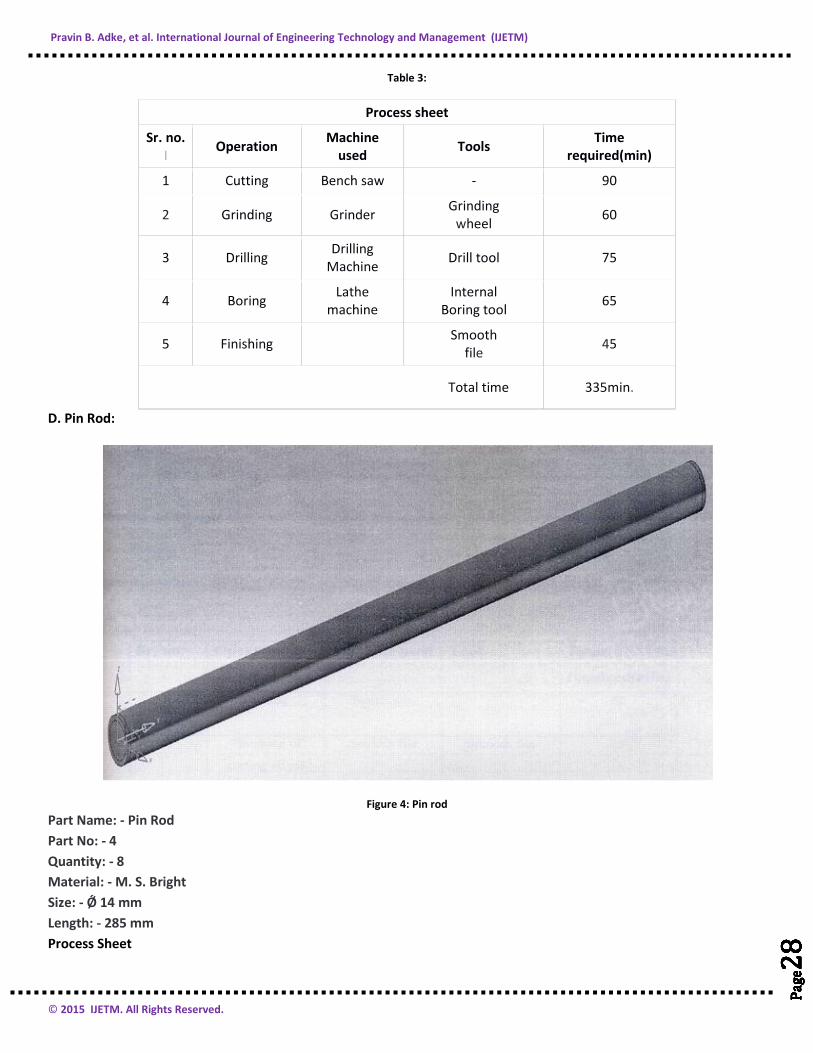
D. Pin Rod:
Figure 4: Pin rod
Part Name: - Pin Rod
Part No: - 4
Quantity: - 8
Material: - M. S. Bright
Size: - Ǿ 14 mm
Length: - 285 mm
Process Sheet

Pravin B. Adke, et al. International Journal of Engineering Technology and Management (IJETM)
© 2015 IJETM. All Rights Reserved.
Pag
e29
P
age2
9
Pag
e29
P
age2
9
Pag
e29
P
age2
9
Pag
e29
P
age2
9
Pag
e29
P
age2
9
Pag
e29
P
age2
9
Pag
e29
P
age2
9
Pag
e29
P
age2
9
Pag
e29
P
age2
9
Pag
e29
P
age2
9
Pag
e29
Table 4:
Sr. no. Operation Machine used Tool Time required(min)
1 Cutting Bench saw 60
2 Finishing of cutting edges Smooth file Smooth file 65
3 Facing Lathe machine Facing tool 90
4 Turning Lathe machine Turning tool 200
5 Chamfering Lathe machine Turning tool 45
6 Finishing Smooth file Smooth file 45
Total time 505min.
E. Nut:
Figure 5: Nut
Part Name: - Nut Part No: - 5 Quantity: - 2 Material: - C. I. Size: - Ǿ 35 * 25 mm Process Sheet

Pravin B. Adke, et al. International Journal of Engineering Technology and Management (IJETM)
© 2015 IJETM. All Rights Reserved.
Pag
e30
P
age3
0
Pag
e30
P
age3
0
Pag
e30
P
age3
0
Pag
e30
P
age3
0
Pag
e30
P
age3
0
Pag
e30
P
age3
0
Pag
e30
P
age3
0
Pag
e30
P
age3
0
Pag
e30
P
age3
0
Pag
e30
P
age3
0
Pag
e30
Table 5:
Sr. no. Operatin Machine used Tool Time
required(min)
1 Cutting Power hacksaw Hacksaw blade 30
2 Facing Lathe m/c Facing tool 40
3 Turning Lathe m/c Turning tool 50
4 Boring Lathe m/c Boring tool 50
5 Threading Lathe m/c Threading tool 45
Total time 215Min.
F. Upper frame:
Figure 6: Upper frame
Part Name: - Upper Frame Part No: - 6 Quantity: - 1 Material: - M. S. Size: - 450* 450* 30 mm Process Sheet
Table 6:
Sr. no. Operation Machine used Tool Time required(min)
1 Cutting of angles Bench hacksaw Hacksaw blade 45
2 Grinding of
cutting edges Hand grinder Grinding wheel 35
3 Welding of angles Welding m/c Welding rod 70
4 Grinding Hand grinder Grinding wheel 35
5 Finishing Chipping hammer 15
Total time 200Min.

Pravin B. Adke, et al. International Journal of Engineering Technology and Management (IJETM)
© 2015 IJETM. All Rights Reserved.
Pag
e31
P
age3
1
Pag
e31
P
age3
1
Pag
e31
P
age3
1
Pag
e31
P
age3
1
Pag
e31
P
age3
1
Pag
e31
P
age3
1
Pag
e31
P
age3
1
Pag
e31
P
age3
1
Pag
e31
P
age3
1
Pag
e31
P
age3
1
Pag
e31
G. Lower Frame:
Figure 7: Lower frame
Part Name: - Lower Frame Part No: - 7 Quantity: - 1 Material: - M. S. Size: - 600*450*30 mm Process Sheet
Table 7:
Sr. no. Operation Machine used Tool Time required(min)
1 Cutting Bench hacksaw Hacksaw blade 35
2 Grinding of cutting edges Hand grinder Grinding wheel 30 3 Welding of angles Welding m/c Welding rods 90
4 Grinding Grinder Grinding wheel 30
5 Finishing Chipping hammer 25
Total time 210Min.
Figure 8: Working table

Pravin B. Adke, et al. International Journal of Engineering Technology and Management (IJETM)
© 2015 IJETM. All Rights Reserved.
Pag
e32
P
age3
2
Pag
e32
P
age3
2
Pag
e32
P
age3
2
Pag
e32
P
age3
2
Pag
e32
P
age3
2
Pag
e32
P
age3
2
Pag
e32
P
age3
2
Pag
e32
P
age3
2
Pag
e32
P
age3
2
Pag
e32
P
age3
2
Pag
e32
Part Name: - Working Table Part No: - 8 Quantity: - 1 Material: - Play wood and M. S. Sheet Size: - 480*480 mm
Table 8:
Sr. no. Operation Machine used Tool Time required(min)
1 Cutting of wood Wood cutting machine Wood cutter 45
2 Finishing of wood File 15
3 Cutting of sheet metal Snap cutting mlc Snap cutter 30
4 Bending Bench vice 60
Total time 150Min.
I. Lever:
Figure 9: Lever
Part Name: - Hand Lever Quantity: - 1 Material: - M. S. Size: - Ǿ 20* 250 mm
Table 8
Sr. no. Operation Machine used Tool Time required(min)
1 Pipe cutting Power hacksaw Hacksaw blade 25
2 Grinding Hand grinder Grinding wheel 20 3 Welding Welding m/c Welding rod 35 4 Grinding Hand grinder Grinding wheel 20 5 Finishing Chipping hammer 15
Total time 115Min.

Pravin B. Adke, et al. International Journal of Engineering Technology and Management (IJETM)
© 2015 IJETM. All Rights Reserved.
Pag
e33
P
age3
3
Pag
e33
P
age3
3
Pag
e33
P
age3
3
Pag
e33
P
age3
3
Pag
e33
P
age3
3
Pag
e33
P
age3
3
Pag
e33
P
age3
3
Pag
e33
P
age3
3
Pag
e33
P
age3
3
Pag
e33
P
age3
3
Pag
e33
3. CONCLUSION: This paper describes the details of nine important components of Toggle jack viz; Screw, Slider Link, H- section, Pin Rod, Nut, Upper Frame, Lower Frame, Working Table and Lever. The process sheet covers every important aspect of design fundamentals, which will be useful for further design considerations in future.
4. REFERENCES:
1. Prof. V. A. Shaikh et al, “Design of Toggle Jack”, International Journal of Science, Technology & Management, Volume No.04, Issue No. 01, January 2015, ISSN (online): 2394-1537.
2. A Text Book of m/c Design: K.S.Khurmi & J.K.Gupta (chapter no.1, page no.625 to 635).
3. A Text Book of introduction to m/c Design: V.B.Bhandari.{ chapt. no.5 types thread profile page no.325 to 331).
4. www.machinedesign.com. (Design of toggle jack).
5. www.ctr.design.co.uk (Information about power screwwww.engineeringbookstore.com. (Theory of power screw).
6. www.engineeringbookstore.com. (Theory of power screw)
7. R.S.Khurmi, J.K.Gupta, “Machine Design Book”, fourteenth edition, S.Chand & company ltd, New Delhi.
8. B.L.Singhal, F.B.Sayyad, “Machine Design Book” (GTU), second edition, Tech-max publication, Pune.
9. P. S.G .Design Data Book, second editon, Koimbtoor. 10. Richard G. Budynas, J. Keith Nisbett, “Mechanical
engg. Design”,ninth edition, Mcgraw hill publication, New Delhi.
11. P.C Sharma and D. K. Aggarwal “Machine Design”, S.K. Kataria & Sons 2009.
12. P.J Shah, “Machine Drawing”, S.Chand Publication.