part design - gwnucadcam.gwnu.ac.kr/subject/catia/pdg/onlinedoc_v5r18_pdg_01.pdfinstantiating a...
TRANSCRIPT

Part Design
Overview
Conventions
What's New?
Getting Started
Using Surfaces and Curves
Joining Surfaces or Curves
Extrapolating Surfaces
Extracting Geometry
Creating Intersections
Creating Projections
Creating Boundaries
Entering the Part Design Workbench
Creating a Pad
Drafting a Face
Filleting an Edge
Editing the Pad
Mirroring the Part
Sketching a Circle from a Face
Creating a Pocket
Shelling the Part
User Tasks
Opening a New CATPart Document
Sketch-Based Features
Creating Pads
Using the Sub-Elements of a Sketch
Creating Up to Next Pads
Creating Up to Last Pads
Creating Up to Plane Pads
Creating Up to Surface Pads
Creating Pads or Pockets from Surfaces
Creating Pads Not Normal to Sketch Planes

Creating Multi-Pads
Creating Drafted Filleted Pads
Creating Pockets
Creating Multi-Length Pockets
Creating Drafted Filleted Pockets
Creating Thin Solids
Creating Shafts
Creating Grooves
Creating Holes
Creating Holes on Non-planar Faces
Locating Holes
Creating Threaded Holes
Creating Ribs
Trimming Ribs and Slots
Creating Slots
Creating Stiffeners
Creating Multi-sections Solids
Creating Removed Multi-sections Solids
Creating Solid Combines
How Sketches are Located in the Specification Tree
Dress-Up Features
Creating Edge Fillets
Creating Variable Radius Fillets
Reshaping Corners
Creating Face-Face Fillets
Creating Chordal Fillets
Creating Tritangent Fillets
Creating Chamfers
Creating Basic Drafts
Creating Advanced Drafts
Creating Variable Angle Drafts
Creating Drafts with Parting Elements
Creating Drafts from Reflect Lines
Creating Shells
Creating Thicknesses
Creating Threads and Taps
Creating Remove Face Features
Creating Replace Face Features
Surface-Based Features

Creating Splits
Creating Thick Surfaces
Creating Close Surface Features
Creating Sew Surfaces
Transformation Features
Creating Translations
Creating Rotations
Creating Symmetries
Transforming Elements From an Axis to Another
Creating Mirrors
Creating Rectangular Patterns
Creating Circular Patterns
Creating User Patterns
Exploding Patterns
Creating Scalings
Transforming Geometry by Affinity
Reference Elements
Creating Points
Creating Lines
Creating Planes
Modifying Parts
Editing parts, bodies, features
Updating Parts
Deleting Features
Deleting Useless or Unreferenced Elements
Deleting Boolean Operations Performed within OGSs
Deactivating Elements
Reordering Features
Reordering Sketch-based Features
Setting Constraints
Setting 3D Constraints
Setting constraints
Modifying Constraints
Replacing Elements
Replacing Elements
Replacing a Body
Changing a Sketch Support
Displaying and Editing Properties
Part Properties

Bodies Properties
Features Properties
Creating Annotations
Annotation Associativity
Creating an Automatic Default Annotation
Querying 3D Annotations
Replacing geometrical elements
Handling Parts
Handling Parts in a Multi-Document Environment
Creating Technological Results
Hybrid Design
Creating Bodies (Hybrid Design)
Creating Features
Location of Operating Bodies in Boolean Operations
Visualization
How to Integrate the Surface World into Solid Modeling
Graphic Properties (Hybrid Design)
Deactivating Your Hybrid Design Environment
Associating Bodies
Inserting a New Body
Inserting a Body into an Ordered Geometrical Set
Managing Geometrical Sets
Managing Ordered Geometrical Sets
Inserting Features into a New Body
Assembling Bodies
Intersecting Bodies
Adding Bodies
Removing Bodies
Trimming Bodies
Remove Lump
Changing a Boolean Operation Into Another One
Editing Copy/Paste Body Link
Using Tools
Editing a List of Elements
Defining Current Objects
Scanning the Part and Defining In Work Objects
Performing a Draft Analysis
Performing a Surface Curvature Analysis
Analyzing Taps and Threads

Creating Datums
Isolating Geometric Elements
Applying a Material
Extracting Geometry
Displaying Parents and Children
Defining An Axis System
Publishing Elements
Working With a Support
Managing the Background Visualization
Measuring Elements
Measuring Between
Measuring Distances between Geometrical Entities
Customizing Measure Between
Measuring Angles
More about Measure Cursors
More about the Measure Between Dialog Box
Measuring Item
Measuring Properties
Customizing Measure Item
More about the Measure Item Dialog Box
Measuring Inertia
Measuring 2D Inertia
Exporting Measure Inertia Results
Notations Used
Inertia Equivalents
Principal Axes
Inertia Matrix with respect to the Origin O
Inertia Matrix with respect to a Point P
Inertia Matrix with respect to an Axis System
Moment of Inertia about an Axis
3D Inertia Properties of a Surface
Updating Measures
Using PowerCopies
Creating PowerCopies
Instantiating PowerCopies
Saving PowerCopies into a Catalog
Instantiating Power Copies Using Step By Step Instantiation
Instantiating Power Copies Using Part Comparison Instantiation
Instantiating a Power Copy From a VB Macro
Reusing your Design
Cutting, Copying, Pasting
Optimizing Part Design Application
Managing User-Defined Features
About User Features
About the User Feature Definition Window
Creating a User Feature
Creating a User Feature
About NLS User Features
Creating a NLS User Feature
Saving a User Feature in a Catalog
Instantiating a User Feature
Instantiating a User Feature From a Catalog, From a Document, From a Selection
Instantiating a User Feature From a VB Macro
Instantiating a User Feature Using the Knowledge Pattern
Modifying a User Feature
Debugging a User Feature
Using the Parent/Children Debug Command
Assigning a Type to a User Feature
Referencing User Features in Search Operations
User Features: Useful Tips
User Features: Limitations
Managing Part and Assembly Templates
About Part and Assembly Templates
About the Document Template Definition Window
Creating a Part Template
Creating a Document Template Containing Meta Inputs
Instantiating a Part Template
Adding an External Document to a Document Template
Instantiating a Document Template Containing Meta Inputs
Document Templates: Methodology
Document Templates: Limitations
Workbench Description
Part Design Menu Bar
Sketch-Based Features Toolbar
Dress-Up Features Toolbar
Surface-Based Features Toolbar
Transformation Features Toolbar

Reference Elements Toolbar
Boolean Operations Toolbar
Sketcher Toolbar
Constraints Toolbar
Analysis Toolbar
Annotations Toolbar
Tools Toolbar
Insert Toolbar
Measure Toolbar
Part Design Specification Tree Icons
Miscellaneous Symbols
Symbols Reflecting Incidents in the Geometry Building
Referenced Geometry
Customizing
Display
General
Part Document
Tolerancing
Display
Manipulators
View/Annotation Plane
Frequently Asked Questions
Draft Features
Edge Fillets
Glossary
Index


Overview
Welcome to the Part Design User’s Guide. This guide is intended to help you get familiar with the Part Design product. It has been designed to show you how to create a part. There are several ways of creating a part. This book covers all the stages for creation of a part.
This overview provides the following information:● Part Design in a Nutshell
● Before Reading this Guide
● Getting the Most out of This Guide
● Accessing Sample Documents
● Conventions Used in this Guide
Part Design in a Nutshell
The Part Design application makes it possible to design precise 3D mechanical
parts with an intuitive and flexible user interface, from sketching in an assembly context to iterative detailed design. Part Design application will enable you to accommodate design requirements for parts of various complexities, from simple to advanced.
This application, which combines the power of feature-based design with the flexibility of a Boolean approach, offers a highly productive and intuitive design environment with multiple design methodologies, such as post-design and local 3D parameterization.
As a scalable product, Part Design can be used in cooperation with other current or future companion products such as Assembly Design and Generative Drafting. The widest application portfolio in the industry is also accessible through interoperability with CATIA Solutions Version 4 to enable support of the full product development process from initial concept to product in operation.
Before Reading this Guide

Before reading this guide, you should be familiar with basic Version 5 concepts such as document windows, standard and view toolbars. Therefore, we recommend that you read the Infrastructure User's Guide that describes generic capabilities common to all Version 5 products. The guide also describes the general layout of V5 and the interoperability between workbenches. You may also like to read the following complementary product guides, for which the appropriate license is required:● Sketcher User's Guide: explains how to sketch 2D elements.
● Wireframe and Surface User's Guide: explains how to create wireframe geometry and surfaces.
Getting the Most out of this Guide
To get the most out of this guide, we suggest you start reading and performing the step-by-step tutorial Getting Started. This tutorial will show you how to create a basic part from scratch.
Once you have finished, you should move on to the next sections dealing with the handling of CATPart data, then the creation and modification of various types of features you will need to construct parts. This guide also presents other Part Design capabilities allowing you to design complex parts. You can also take a look at the sections describing the Part Design Workbench at the end of the guide.
Accessing Sample DocumentsTo perform the scenarios, you will be using sample documents contained in the online/prtug/samples folder.
When samples belong to capabilities common to different products, those samples will be found in the online/cfysm_XX/samples folder.
For more information about this, see Accessing Sample Documents in the Infrastructure User's Guide.
Conventions Used in this GuideTo learn more about the conventions used in this guide, see the Conventions section.

ConventionsCertain conventions are used in CATIA, ENOVIA and DELMIA documentation to help you recognize and understand important concepts and specifications. This page describes:● Graphics Conventions
● Text Conventions
● Mouse Usage
● Navigation compass
Graphic Conventions
The three categories of graphic conventions used are as follows:● Graphic conventions used to structure the tasks
● Graphic conventions used to indicate the configuration required
● Graphic conventions used in the table of contents
Graphic Conventions Used to Structure Tasks
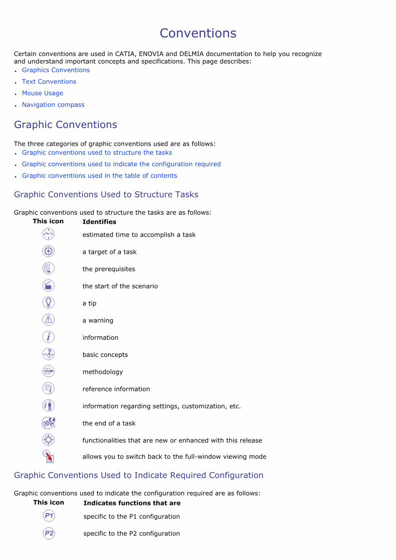
Graphic conventions used to structure the tasks are as follows:This icon Identifies
estimated time to accomplish a task
a target of a task
the prerequisites
the start of the scenario
a tip
a warning
information
basic concepts
methodology
reference information
information regarding settings, customization, etc.
the end of a task
functionalities that are new or enhanced with this release
allows you to switch back to the full-window viewing mode
Graphic Conventions Used to Indicate Required Configuration
Graphic conventions used to indicate the configuration required are as follows:This icon Indicates functions that are
specific to the P1 configuration
specific to the P2 configuration
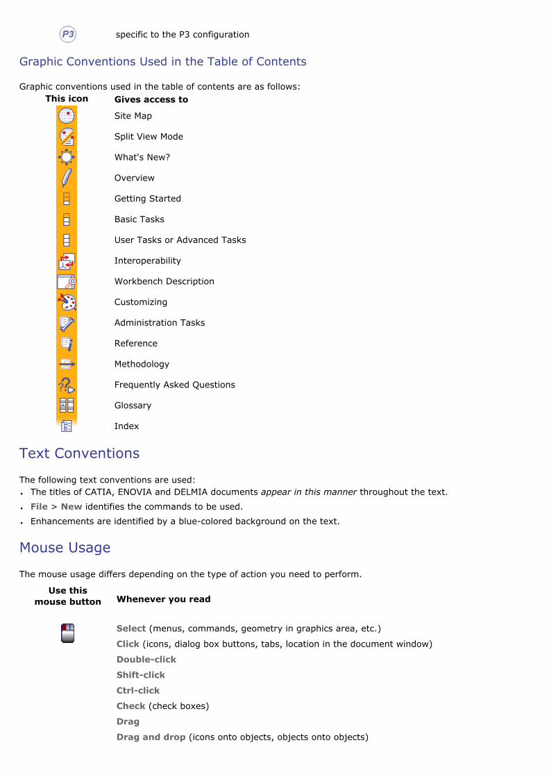
specific to the P3 configuration
Graphic Conventions Used in the Table of Contents
Graphic conventions used in the table of contents are as follows:This icon Gives access to
Site Map
Split View Mode
What's New?
Overview
Getting Started
Basic Tasks
User Tasks or Advanced Tasks
Interoperability
Workbench Description
Customizing
Administration Tasks
Reference
Methodology
Frequently Asked Questions
Glossary
Index
Text Conventions
The following text conventions are used:● The titles of CATIA, ENOVIA and DELMIA documents appear in this manner throughout the text.
● File > New identifies the commands to be used.
● Enhancements are identified by a blue-colored background on the text.
Mouse Usage
The mouse usage differs depending on the type of action you need to perform.
Use this mouse button Whenever you read
Select (menus, commands, geometry in graphics area, etc.)
Click (icons, dialog box buttons, tabs, location in the document window)
Double-click
Shift-click
Ctrl-click
Check (check boxes)
Drag
Drag and drop (icons onto objects, objects onto objects)

Drag
Move
Right-click (to select contextual menu)
Navigation Compass
The navigation compass is located in the guide banner next to the guide name. It lets you navigate through the information in the guide.
Use this button To go
Back to the last page visited
Forward through links previously visited
Up to the parent level
Down to the child level
To the previous page at the same level
To the next page at the same level
What's New?
New Functionalities
Creating Chordal FilletsThe Chordal Fillet command is used to control the width of the fillet (distance between the 2 rolling edges) which is also called as Chordal length.
Transforming Elements From an Axis to AnotherYou can transform geometry positioned according to a given axis system into a new axis system. The geometry is duplicated and positioned according to the new axis system.
Transforming Geometry by AffinityYou can transform geometry by means of an affinity operation.
Enhanced Functionalities
Creating Edge FilletsThe Conical parameter option allows you to vary the section of the fillet.
Creating Face-Face Fillets The Conical parameter option allows you to vary the section of the fillet.
Creating Variable Radius FilletsThe Conical parameter option allows you to vary the section of the fillet.
Thread Up To Plane & Support DepthYou can use a planar geometrical element as limiting thread/tap depth element or set the thread depth with the length of the support. This capability is available for Creating Threads and Taps and Creating Threaded Holes.
Editing Copy/Paste Body Link This capability gives more flexibility to the generic solid feature generated with a Copy/Paste Special as Result with Link operation on a body, by being able to edit it.
Reordering FeaturesThis capability aims at replugging features that use sub-elements (such as edges, faces and vertices) on the features on which they resolve themselves.
Customizing Settings
Inherit Colors from the Reference FeatureThis option assigns the color of the reference feature to its copy obtained using Copy Paste As Result With Link.
Setting Small ScaleThe Small Scale option allows you to create smaller geometries with a high accuracy of less than 1 micron.

Getting Started
Before getting into the detailed instructions for using parts, the following tutorial aims at giving you a feel as to what you can do with the product. It provides a step-by-step scenario showing you how to use key functionalities.
The main tasks described in this section are:
Using Surfaces and Curves Entering the Part Design Workbench
Creating a Pad Drafting a Face Filleting an Edge Editing the Pad
Mirroring the Part Sketching a Circle from a Face
Creating a Pocket Shelling the Part
All together, the tasks should take about ten minutes to complete.
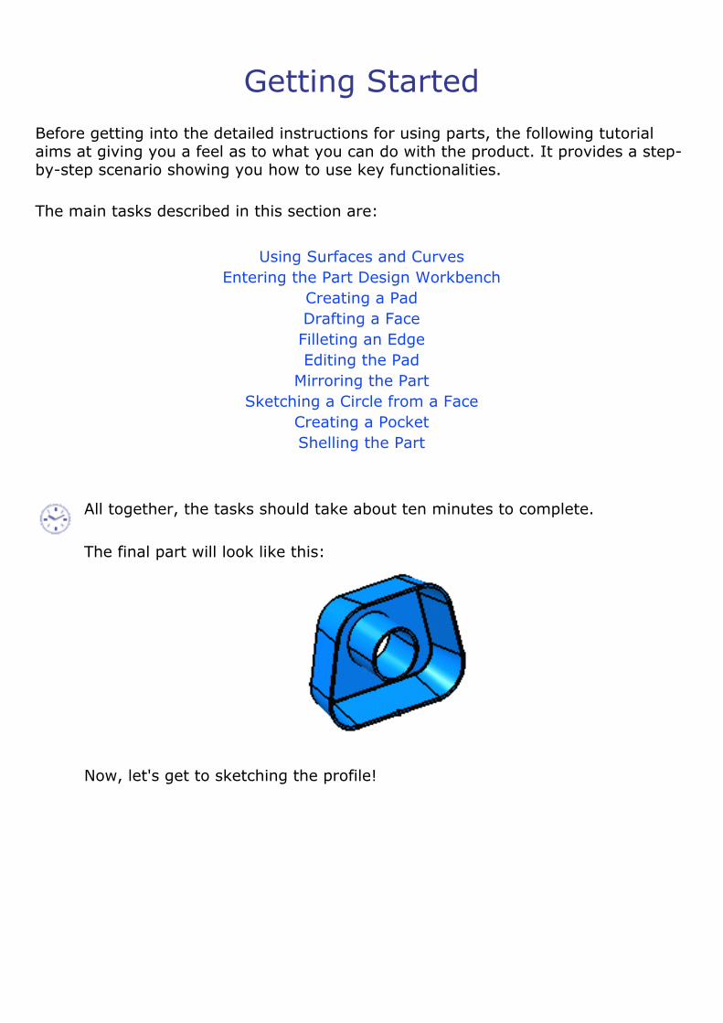
The final part will look like this:
Now, let's get to sketching the profile!
Using Surfaces and Curves
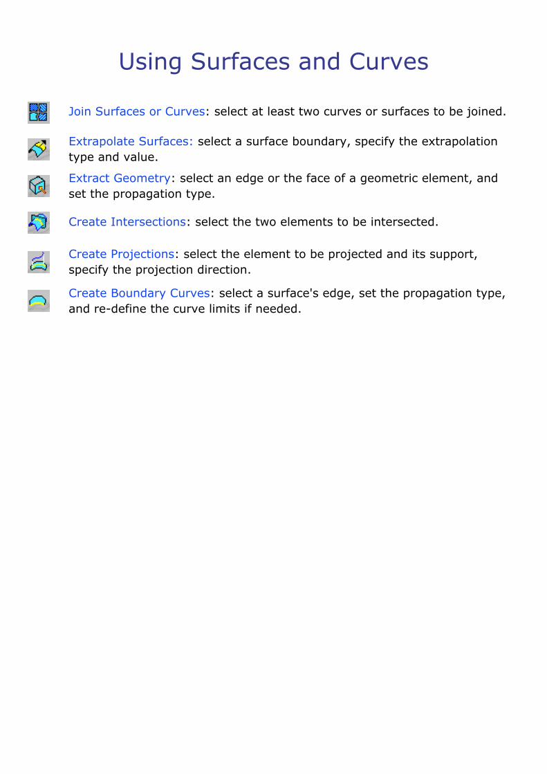
Join Surfaces or Curves: select at least two curves or surfaces to be joined.
Extrapolate Surfaces: select a surface boundary, specify the extrapolation type and value.
Extract Geometry: select an edge or the face of a geometric element, and set the propagation type.
Create Intersections: select the two elements to be intersected.
Create Projections: select the element to be projected and its support, specify the projection direction.
Create Boundary Curves: select a surface's edge, set the propagation type, and re-define the curve limits if needed.

Joining Surfaces or Curves This task shows how to join surfaces or curves. This involves:● using the check options
● removing sub-elements
● using the federation capability
Open the Join1.CATPart document.
1. Click Join .The Join Definition dialog box appears.
In Part Design workbench, the Join capability is available as a contextual command named 'Create Join' that you can access from Sketch-based features dialog boxes.
2. Select the surfaces or curves to be joined.

3. You can edit the list of elements to be joined:
�❍ by selecting elements in the geometry: ■ Standard selection (no button clicked):
when you click an unlisted element, it is added to the list when you click a listed element, it is removed from the list
■ Add Mode: when you click an unlisted element, it is added to the list when you click a listed element, it remains in the list
■ Remove Mode: when you click an unlisted element, the list is unchanged when you click a listed element, it removed from the list
�❍ by selecting an element in the list then using the Clear Selection or Replace Selection contextual menu items.
If you double-click Add Mode or Remove Mode, the chosen mode is permanent, i.e. successively selecting elements will add/remove them. However, if you click only once, only the next selected element is added or removed. You only have to click the button again, or click another one, to deactivate the mode.
4. Right-click the elements from the list and choose the Check Selection contextual command.
This lets you check whether an element to be joined presents any intersection (i.e. at least one common point) with other elements prior to creating the joined surface. If this command is not launched, possible intersections will not be detected.The Checker dialog box is displayed, containing the list of domains (i.e. sets of connected cells) belonging to the selected elements from the Elements To Join list.
5. Click Preview.
�❍ An Information message is issued when no intersection is found.

�❍ When an element is self-intersecting, or when several elements intersect, a text is displayed on the geometry, where the intersection is detected.
6. Click Cancel to return to the Join Definition dialog box.
7. Right-click the elements again and choose the Propagation options to allow the selection of elements of same dimension.
�❍ Distance Propagation: the tolerance corresponds to the Merging distance value.
�❍ Angular Propagation: the tolerance corresponds to the Angular Threshold value, if defined. Otherwise, it corresponds to the G1 tolerance value as defined in the part.
Each new element found by propagation of the selected element(s) is highlighted and added to the Elements To Join list.
Note that:�❍ The initial element to propagate cannot be a sub-element,
�❍ Forks stop the propagation,
�❍ Intersections are not detected.
8. Click Preview in the Join Definition dialog box.
The joined element is previewed, and its orientation displayed. Click the red arrow to invert it if needed.

The join is oriented according to the first element in the list. If you change this element, the join's orientation is automatically set to match the orientation of the new topmost element in the list.
Using the check options
9. Check Check tangency to find out whether the elements to be joined are tangent. If they are not, and the option is checked, an error message is issued when you click Preview...
... and elements in error are highlighted in the 3D geometry once you have clicked OK in the Update Error dialog box:

This option works for an angular resolution of 0.5 degree.
10. Check Check connexity to find out whether the elements to be joined are connex. If they are not, and the button is checked, an error message is issued indicating the number of connex domains in the resulting join and elements in error are highlighted in the 3D geometry.
When clicking Preview, the free boundaries are highlighted, and help you detect where the joined element is not connex.If two elements are not connex and Check connexity is deselected, the Multi-Result Management dialog box is displayed.
11. Check Check manifold to find out whether the resulting join is manifold.
Check manifold is only available with curves.
12. You can check Simplify the result to allow the system to automatically reduce the number of elements (faces or edges) in the resulting join whenever possible.
13. You can check Ignore erroneous elements to let the system ignore surfaces and edges that would not allow the join to be created.
14. You can also set the tolerance at which two elements are considered as being only one using the Merging distance.
By default, the value is set to 0.001 mm and corresponds to the value defined in Tools > Options. To find out more about the merging distance value, refer to the General Settings chapter.
It is not recommended to join two geometric elements with a merging distance exactly equal to the distance between these elements.
15. Check the Angular Threshold option and specify the angle value below which the elements are to be joined.
If the angle value on the edge between two elements is greater than the Angle Threshold value, the elements are not joined. This is particularly useful to avoid joining overlapping elements.
This option only applies to edges merged during the join computation.
Removing Sub-Elements16. Click the Sub-Elements To Remove tab to display the list of sub-elements in the

join.
These sub-elements are elements making up the elements selected to create the join, such as separate faces of a surface for example, that are to be removed from the join currently being created.
You can edit the sub-elements list as described above for the list of elements to be joined.
17. Check Create join with sub-elements to create a second join, made of all the sub-elements displayed in the list, i.e. those that are not to be joined in the first join.
�❍ This option is active only when creating the first join, not when editing it.
�❍ It is not available when the joined surface belongs to an ordered geometrical set or a partbody created in an hybrid environment.
�❍ A message is displayed to inform you of the creation of a second join.
18. Click OK to create the joined surface or curve.
The surface or curve (identified as Join.xxx) is added to the specification tree.
Sometimes elements are so close that it is not easy to see if they present a gap or not, even though they are joined. Check the Surfaces' Boundaries option from the Tools > Options > General > Display > Visualization tab.
Using the Federation Capability
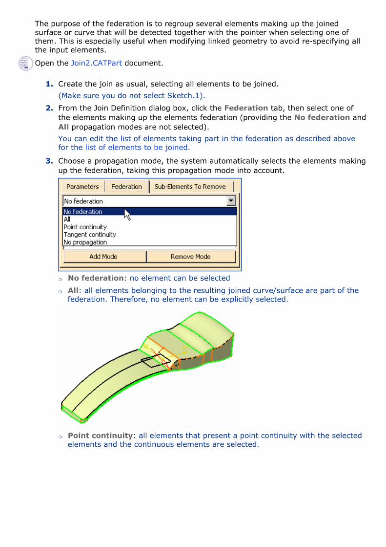
The purpose of the federation is to regroup several elements making up the joined surface or curve that will be detected together with the pointer when selecting one of them. This is especially useful when modifying linked geometry to avoid re-specifying all the input elements. Open the Join2.CATPart document.
1. Create the join as usual, selecting all elements to be joined.
(Make sure you do not select Sketch.1).
2. From the Join Definition dialog box, click the Federation tab, then select one of the elements making up the elements federation (providing the No federation and All propagation modes are not selected).
You can edit the list of elements taking part in the federation as described above for the list of elements to be joined.
3. Choose a propagation mode, the system automatically selects the elements making up the federation, taking this propagation mode into account.
�❍ No federation: no element can be selected
�❍ All: all elements belonging to the resulting joined curve/surface are part of the federation. Therefore, no element can be explicitly selected.
�❍ Point continuity: all elements that present a point continuity with the selected elements and the continuous elements are selected.

Tangent continuity: all the elements that are tangent to the selected element, and the ones tangent to it, are part of the federation.Here, only the top faces of the joined surface are detected, not the lateral faces.
To federate a surface and its boundaries in tangency, you need to select the face as well as the edges: both face and edges will be federated.
�❍ No propagation: only the elements explicitly selected are part of the federation.
4. Choose the Tangency continuity propagation mode.
5. Move to the Part Design workbench (select Start > Mechanical Design > Part
Design), select the Sketch.1, and click Pad to create an up to surface pad, using the joined surface as the limiting surface.
6. Select the front edge of the pad, click Edge Fillet and create a 2mm fillet.
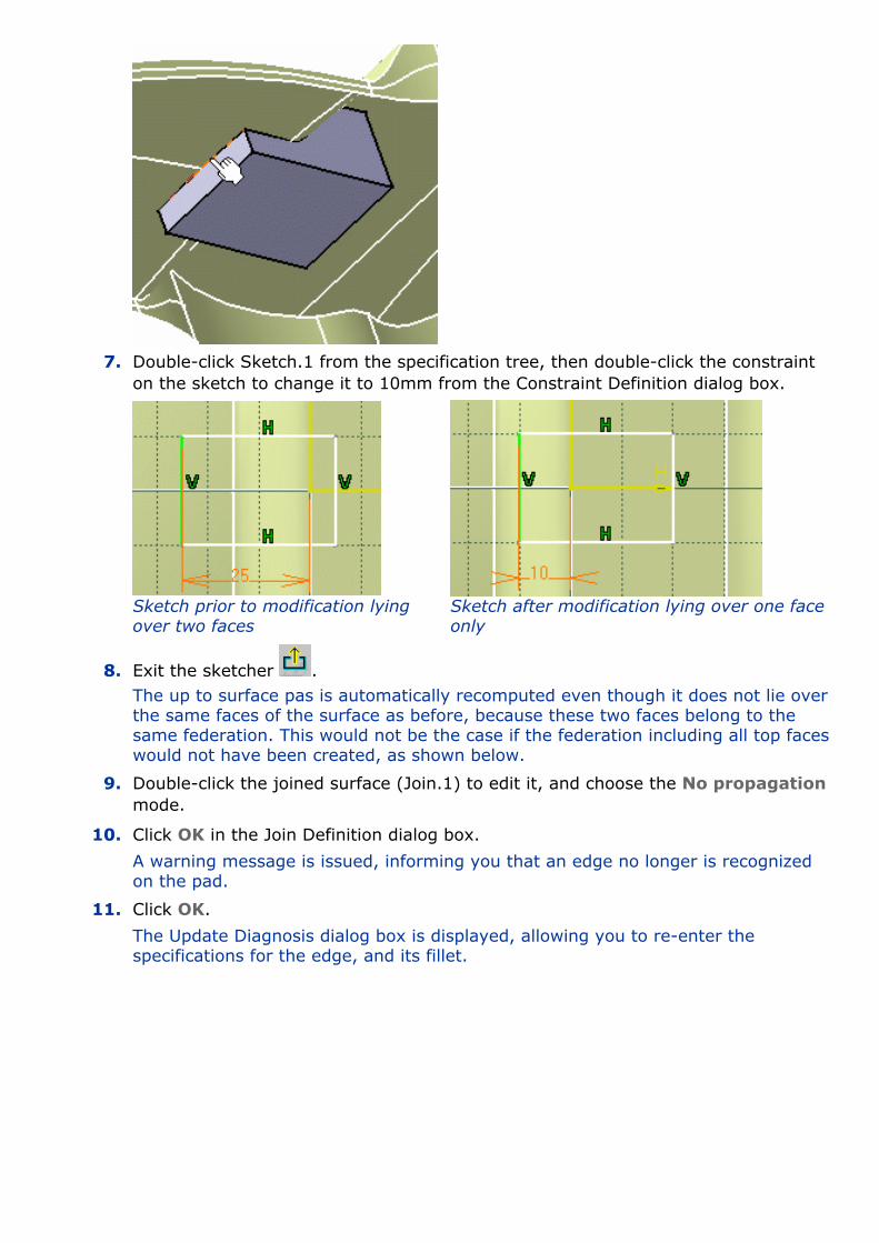
7. Double-click Sketch.1 from the specification tree, then double-click the constraint on the sketch to change it to 10mm from the Constraint Definition dialog box.
Sketch prior to modification lying over two faces Sketch after modification lying over one face
only
8. Exit the sketcher .The up to surface pas is automatically recomputed even though it does not lie over the same faces of the surface as before, because these two faces belong to the same federation. This would not be the case if the federation including all top faces would not have been created, as shown below.
9. Double-click the joined surface (Join.1) to edit it, and choose the No propagation mode.
10. Click OK in the Join Definition dialog box.
A warning message is issued, informing you that an edge no longer is recognized on the pad.
11. Click OK.
The Update Diagnosis dialog box is displayed, allowing you to re-enter the specifications for the edge, and its fillet.

You then need to edit the edge and re-do the fillet to obtain the previous pad up to the joined surface.
12. Select the Edge.1 line, click the Edit button, and re-select the pad's edge in the geometry.
13. Click OK in the Edit dialog box.
The fillet is recomputed based on the correct edge.
Extrapolating Surfaces
This task shows you how to extrapolate a surface boundary.
Open the Extrapolate1.CATPart document.
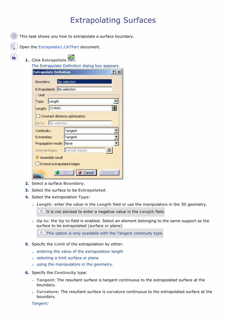
1. Click Extrapolate .The Extrapolate Definition dialog box appears.
2. Select a surface Boundary.
3. Select the surface to be Extrapolated.
4. Select the extrapolation Type:
�❍ Length: enter the value in the Length field or use the manipulators in the 3D geometry.
It is not advised to enter a negative value in the Length field.
�❍ Up to: the Up to field is enabled. Select an element belonging to the same support as the surface to be extrapolated (surface or plane).
This option is only available with the Tangent continuity type.
5. Specify the Limit of the extrapolation by either:
�❍ entering the value of the extrapolation length
�❍ selecting a limit surface or plane
�❍ using the manipulators in the geometry.
6. Specify the Continuity type:
�❍ Tangent: The resultant surface is tangent continuous to the extrapolated surface at the boundary.
�❍ Curvature: The resultant surface is curvature continuous to the extrapolated surface at the boundary.
Tangent:

Curvature:
7. Specify Extremities conditions between the extrapolated surface and the support surface.
This option is now available with the Curvature continuity type.
�❍ Tangent: The extrapolation sides are tangent to the edges adjacent to the surface boundary.
�❍ Normal: The extrapolation sides are normal to the original surface boundary.
Tangent (Tangent continuity)
Normal (Curvature continuity)
8. Specify the Propagation type:
�❍ Tangency continuity: To propagate the extrapolation to the boundary's adjacent edges.
�❍ Point continuity: To propagate the extrapolation around all the boundary's vertices.
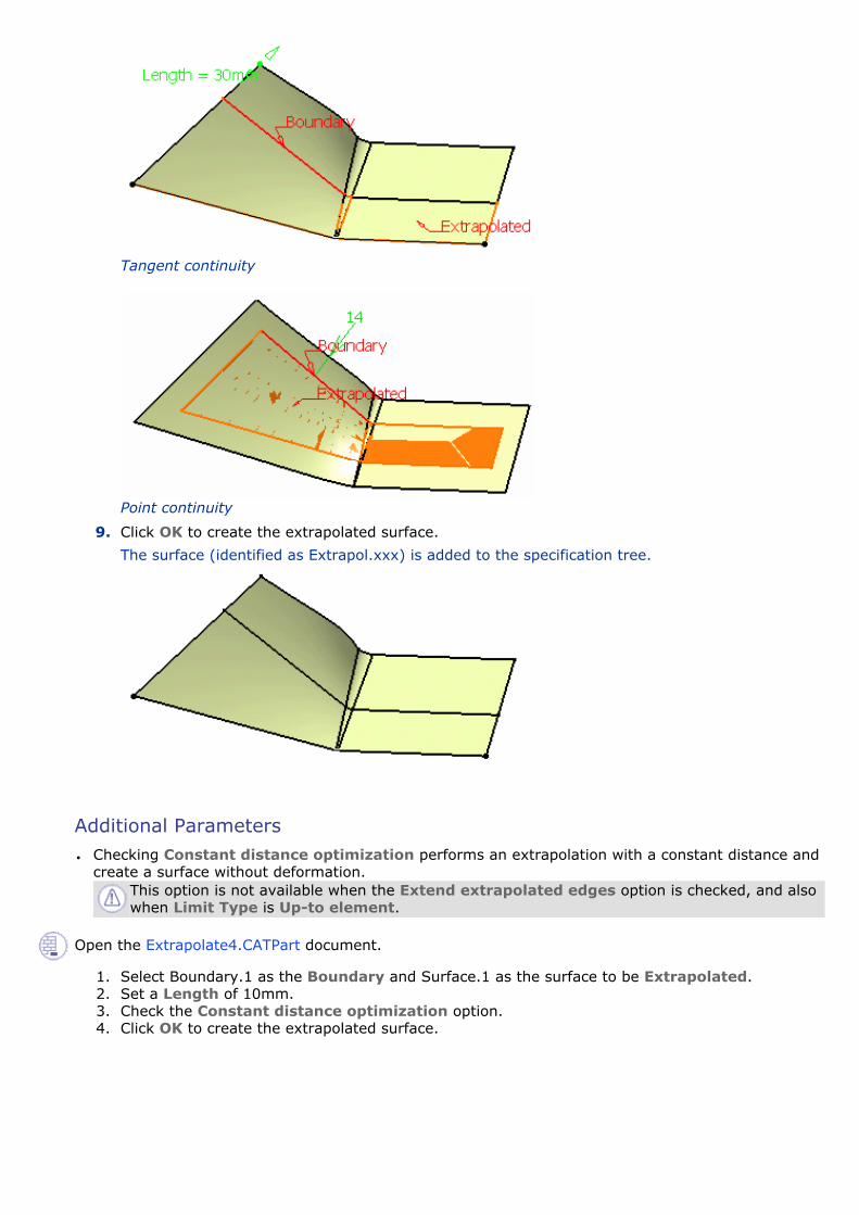
Tangent continuity
Point continuity
9. Click OK to create the extrapolated surface.
The surface (identified as Extrapol.xxx) is added to the specification tree.
Additional Parameters ● Checking Constant distance optimization performs an extrapolation with a constant distance and
create a surface without deformation.This option is not available when the Extend extrapolated edges option is checked, and also when Limit Type is Up-to element.
Open the Extrapolate4.CATPart document.
1. Select Boundary.1 as the Boundary and Surface.1 as the surface to be Extrapolated.2. Set a Length of 10mm.3. Check the Constant distance optimization option.4. Click OK to create the extrapolated surface.

Constant distance optimization option checked
Constant distance optimization option unchecked
● Defining Internal Edges enables to determine a privileged direction for the extrapolation. You can select one or more edges (in the following example we selected the edge of Surface.1) that will be extrapolated in tangency. You can also select a vertex once you have selected an edge in order to give an orientation to the extrapolation.
● You can only select edges in contact with the boundary.
● This option is not available with the Curvature continuity type and with the Wireframe and Surface product.
One edge selected Two edges selected
● Checking Assemble result enables the extrapolated surface to be assembled to the support
surface.
● Checking Extend extrapolated edges reconnects the features based on elements of the
extrapolated surface. This option is especially useful if you work within an ordered geometrical set environment. Open the Extrapolate3.CATPart document.

1. Set Extrude.1 as the current object.
2. Select the boundary of Extrude.1 and Extrude.1 as the surface to be extrapolated.
Extrude.3 is automatically rerouted, as well as all edges based on Extrude.1.
�❍ This option is only available when both Continuity and Extremity types are specified as Tangent, and when Assemble result is selected.
�❍ It is not available when Constant distance optimization is selected.
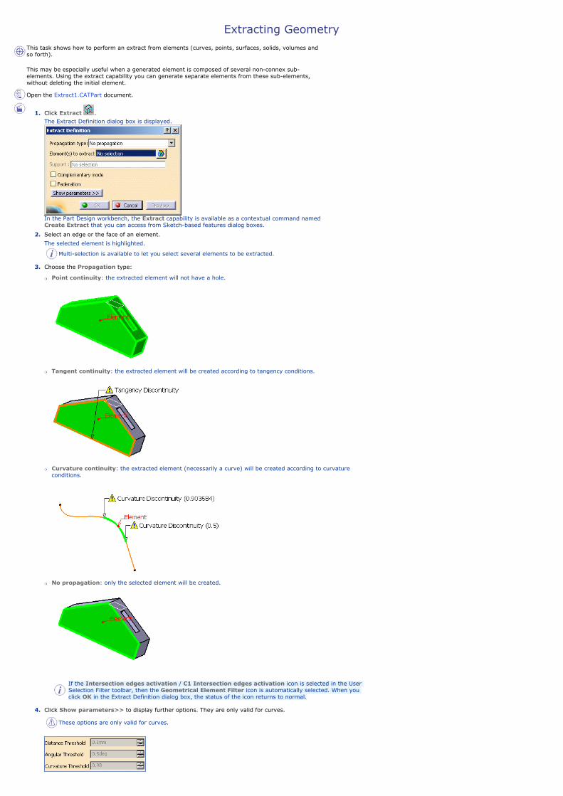
Extracting Geometry This task shows how to perform an extract from elements (curves, points, surfaces, solids, volumes and so forth).
This may be especially useful when a generated element is composed of several non-connex sub-elements. Using the extract capability you can generate separate elements from these sub-elements, without deleting the initial element. Open the Extract1.CATPart document.
1. Click Extract .The Extract Definition dialog box is displayed.
In the Part Design workbench, the Extract capability is available as a contextual command named Create Extract that you can access from Sketch-based features dialog boxes.
2. Select an edge or the face of an element.
The selected element is highlighted.
Multi-selection is available to let you select several elements to be extracted.
3. Choose the Propagation type:
�❍ Point continuity: the extracted element will not have a hole.
�❍ Tangent continuity: the extracted element will be created according to tangency conditions.
�❍ Curvature continuity: the extracted element (necessarily a curve) will be created according to curvature conditions.
�❍ No propagation: only the selected element will be created.
If the Intersection edges activation / C1 Intersection edges activation icon is selected in the User Selection Filter toolbar, then the Geometrical Element Filter icon is automatically selected. When you click OK in the Extract Definition dialog box, the status of the icon returns to normal.
4. Click Show parameters>> to display further options. They are only valid for curves.
These options are only valid for curves.

�❍ Distance Threshold: specifies the distance value between 0.001mm and 0.1 mm below which the elements are to be extracted.
■ The default value is 0.1mm, except if a Merging Distance has been defined different from 0.001mm in Tools > Options. In this case, the Distance Threshold value is initialized with the Merging Distance value. To have further information, refer to the General Settings chapter.
■ It is available with all propagation types, except for the No propagation type.
�❍ Angular Threshold: specify the angle value between 0.5 degree and 5 degree below which the elements are to be extracted (the default value is 0.5deg)
�❍ Curvature Threshold: specifies a ratio between 0 and 1 which is defined as follows:
if ||Rho1-Rho2|| / max (||Rho2||,||Rho1||) < (1-r)/r where Rho1 is the curvature vector on one side of the discontinuity, Rho2 the curvature vector on the other side, and r the ratio specified by the user; then the discontinuity is smoothed.
For example, r=1 corresponds to a continuous curvature and r=0.98 to the model tolerance (default value). A great discontinuity will require a low r to be taken into account.
Curvature Threshold = 0.98 Curvature Threshold = 0.80 Curvature Threshold = 0.50To sum up:�❍ when Point continuity is selected, only the Distance Threshold is activated
�❍ when Tangent continuity is selected, both Distance and Angular Thresholds are activated
�❍ when Curvature continuity is selected, all Thresholds are activated.
5. Click OK to extract the element.
The extracted element (identified as Extract.xxx) is added to the specification tree.
Additional Parameters
● Checking Complementary mode highlights and therefore selects the elements that were not
previously selected, while deselecting the elements that were explicitly selected.
● Checking Federation generates groups of elements belonging to the resulting extracted element that will be detected together with the pointer when selecting one of its sub-elements. For further information, see Using the Federation Capability.
● You can select a volume as the element to be extracted. To do so, you can either:
�❍ select the volume in the specification tree, or
�❍ use the User Selection Filter toolbar and select the Volume Filter mode. For further information, refer to the Selecting Using A Filter chapter in the CATIA Infrastructure User's Guide.
In both cases, the result of the extraction is the same whatever the chosen propagation type.
● If you extract an internal edge that you want to propagate, and there is an ambiguity about the propagation side, a warning message is issued and you are prompted to select a support face. In this case, the dialog box dynamically updates and the Support field is automatically filled in. In all other cases, you are advised to select a support element so that the orientation of the resulting extract feature remains the same even if the geometry is modified.
Creating Contextual Extracts
Some commands allow the creation of contextual extracts using the right-mouse button. They are aggregated to the feature using them and put in no show. Here is an example with the Parallel Curve command when right-clicking the Curve field:

● If you select the Create Extract contextual command, the Extract Definition dialog box opens.
● If you select the Create Extract (in point) or Create Extract (in tangency) contextual command, no dialog box opens.Both commands let you create extracts with a pre-defined propagation. You just need to select a sub-element such as wire edge, border edges, face, sub-elements of a volume or a solid.
You cannot select edges as a support is needed.
You need to leave the mouse on the pre-selected sub-element to preview and compute the propagation (in green):
Editing Extracts
When editing extracts, the multi-selection capability is not available: if you select another element to be extracted, it is not appended to the list but replaces the former element.
Miscellaneous
● In a .CATProduct document containing several parts, you can use the extract capability in the current part from the selection of an element in another part, provided the propagation type is set to No Propagation. In this case, a curve (respectively a surface or point) is created in the current part if the selected element is a curve (respectively a surface or point); the Extract parent therefore being the created curve (respectively the surface or point). Note: �❍ if another propagation type is selected, the extraction is impossible and an error message is issued.
�❍ when editing the extract, you can change the propagation type providing the parent belongs to the current part.
�❍ in the current part, if you select an element using the Tangent, Point or Curvature continuity as the propagation type, a warning is issued and you have to select No propagation instead.
● If the selected element is not tangent continuous and the propagation type is set to Tangent continuity, an error message is issued.
● If the selected element is a wire that is not curvature continuous and the propagation type is set to Curvature continuity, an error message is issued.
● If the selected element has a support face and is not a surface, even though the Complementary mode option is checked, the Complementary mode will not be taken into account for the extraction and the option will therefore be inactive. After the extraction, the option will be available again.
● If the selected element is a border edge, the propagation is done along the boundary of the support and does not take into account internal edges.
● When the result of an extract is not connex (during creation or edition) due to naming ambiguity, you can then select the part to keep to solve the ambiguity.
● If two elements have a same name and are distant of less than 0.1mm, the naming ambiguity mechanism fails and an error message is issued.
● You cannot copy/paste an extracted element from a document to another. If you wish to do so, you need to copy/paste the initial element first into the second document then perform the extraction.
● If there is several solutions for the propagation, the computation of the extract stops at the junction point.

Creating IntersectionsThis task shows you how to create wireframe geometry by intersecting elements.
You can intersect:
● wireframe elements
● solid elements
● surfaces
Open the Intersection1.CATPart document.
1. Click Intersection .
The Intersection Definition dialog box appears as well as the Tools Palette. For further information about the Tools Palette, refer to Selecting Using Selection Traps in the CATIA Infrastructure User's Guide.
2. Select the two elements to be intersected.
The intersection is displayed.

Multi-selection is available on the first and second selection, meaning that you can select several elements to be intersected as well as several intersecting elements. For instance you can select a whole geometrical set.
3. Choose the type of intersection to be displayed.
�❍ a Curve (when intersecting two curves):
�❍ Points (when intersecting two curves):
�❍ a Contour: when intersecting a solid element with a surface :
�❍ a Face: when intersecting a solid element with a surface (we increased the transparency degree on the pad and surface):

4. Click OK to create the intersection element.
This element (identified as Intersect.xxx) is added to the specification tree.
The above example shows the line resulting from the intersection of a plane and a surface
The above example shows the curve resulting from the intersection of two surfaces
Additional Parameters
Several options can be defined to improve the preciseness of the intersection.
Open the Intersection2.CATPart document.

● Extend linear supports for intersection enables to extend the first, second or both elements. Both options are unchecked by default.Here is an example with the option checked for both elements.
● Extrapolate intersection on first element enables to perform an extrapolation on the first selected element, in the case of a surface-surface intersection. In all the other cases, the option will be grayed.
Intersection with the Extrapolation option unchecked Intersection with the Extrapolation
option checked
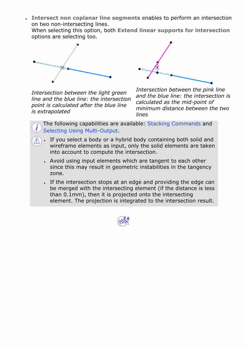
● Intersect non coplanar line segments enables to perform an intersection on two non-intersecting lines. When selecting this option, both Extend linear supports for intersection options are selecting too.
Intersection between the light green line and the blue line: the intersection point is calculated after the blue line is extrapolated
Intersection between the pink line and the blue line: the intersection is calculated as the mid-point of minimum distance between the two lines
The following capabilities are available: Stacking Commands and Selecting Using Multi-Output.
● If you select a body or a hybrid body containing both solid and wireframe elements as input, only the solid elements are taken into account to compute the intersection.
● Avoid using input elements which are tangent to each other since this may result in geometric instabilities in the tangency zone.
● If the intersection stops at an edge and providing the edge can be merged with the intersecting element (if the distance is less than 0.1mm), then it is projected onto the intersecting element. The projection is integrated to the intersection result.

Creating Projections This task shows you how to create geometry by projecting one or more elements onto a support. The projection may be normal or along a direction. You can project:
● a point onto a surface or wireframe support
● wireframe geometry onto a surface support
● any combination of points and wireframe onto a surface support.
Generally speaking, the projection operation has a derivative effect, meaning that there may be a continuity loss when projecting an element onto another. If the initial element presents a curvature continuity, the resulting projected element presents at least a tangency continuity. If the initial element presents a tangency continuity, the resulting projected element presents at least a point continuity.
Open the Projection1.CATPart document.
1. Click Projection .The Projection Definition dialog box appears as well as the Tools Palette. For further information about the Tools Palette, refer to Selecting Using Selection Traps in the CATIA Infrastructure User's Guide.
2. Select the element to be Projected.
You can select several elements to be projected. In this case, the Projected field indicates: x elements.

3. Select the Support element.
4. Use the combo to specify the direction type for the projection:
�❍ Normal: the projection is done normal to the support element.
�❍ Along a direction: you need to select a line to take its orientation as the translation direction or a plane to take its normal as the translation direction.You can also specify the direction by means of X, Y, Z vector components by using the contextual menu on the Direction field.
5. Whenever several projections are possible, the nearest projection can be kept by

checking Nearest Solution.
If this option is not checked, the Multi-Result Management dialog box opens to let you choose the solution. Check Keep all the sub-elements to have a complete solution.
If the elements have the same distance to the support, an error message is issued. This distance corresponds to the maximum distance between a point on the projected element and its projection onto the support.
6. Click OK to create the projection element.
The projection (identified as Project.xxx) is added to the specification tree.
Smoothing Parameters
You can smooth the element to be projected by checking either:
● None: deactivates the smoothing resultWith support surface: the smoothing is performed according to the support. As a consequence, the resulting smoothed curve inherits support discontinuities.
● Tangency: enhances the current continuity to tangent continuity
● Curvature: enhances the current continuity to curvature continuity
● You can specify the maximum deviation for G1 or G2 smoothing by entering a value or using the spinners.
If the element cannot be smoothed correctly, a warning message is issued.
Moreover, a topology simplification is automatically performed for G2 vertices: cells with a curvature continuity are merged.
Only small discontinuities are smoothed in order to keep the curve's sharp vertices.
Without support surface:● 3D Smoothing: the smoothing is performed without specifying any support surface.
As a consequence, the resulting smoothed curve has a better continuity quality and is not exactly laid down on the surface. As a consequence, you may need to activate the Tolerant laydown option. Refer to the Customizing General Settings chapter. This option is available if you previously select the Tangency or Curvature smoothing type.

With 3D smoothing option checked With 3D smoothing option unchecked
The following capabilities are available: Stacking Commands and Selecting Using Multi-Output.

Creating Boundaries This task shows how to create the boundary curve of a surface or the boundary point of a curve.
Open the Boundaries1.CATPart document.
1. Click Boundary .The Boundary Definition dialog box appears.
2. Use the combo to choose the Propagation type:
�❍ Complete boundary: the selected edge is propagated around the entire surface boundary.
�❍ Point continuity: the selected edge is propagated around the surface boundary until a point discontinuity is met.
�❍ Tangent continuity: the selected edge is propagated around the surface boundary until a tangent discontinuity is met.
�❍ No propagation: no propagation or continuity condition is imposed, only the selected edge is kept.
You can select the propagation type before selecting an edge.
3. Select a Surface edge.
The boundary curve is displayed according to the selected propagation type.
No propagation Tangent continuity
Point continuity Complete boundary
4. You can relimit the boundary curve by means of two elements.

If you relimit a closed curve by means of only one element, a point on curve for instance, the closure vertex will be moved to the relimitation point, allowing this point to be used by other features.
5. Click OK to create the boundary curve.
The curve (identified as Boundary.xxx) is added to the specification tree.You cannot copy/paste a boundary from a document to another. If you wish to do so, you need to copy/paste the surface first into the second document then create the boundary.
About the Propagation Type�❍ If you select the surface directly, the Propagation type no longer is available, as the
complete boundary is automatically generated.
Provided the generated boundary curve is continuous, you can still select a limiting point to limit the boundary.
Using the red arrow, you can then invert the propagation of the limited boundary.
�❍ If you select a curve which has an open contour, the Propagation type becomes available: choose the No Propagation type and select the curve again. The extremum points will define the boundary result.


Entering the Part Design Workbench This task shows you how to enter the Part Design workbench.
1. Select File > New... (or click the New icon). The New dialog box is displayed, allowing you to choose the type of document you need.
2. Select Part in the List of Types field.
3. Click OK. The New Part dialog appears if your session is configured as explained in the Customizing chapter of this guide. For more information, refer to the documentation related to the Part Document tab.
Hybrid Design By default, the Enable hybrid design option is on, meaning that you are allowed to insert wireframe and surface elements in bodies.
To facilitate your design, we recommend you never change this option during your session.
4. Click OK to validate your preferences and close the New Part dialog box. The Part Design workbench is loaded and an empty CATPart document opens.
If the New Part dialog box does not appear, the Part Design workbench is immediately loaded and an empty CATPart document opens.

The commands for creating and editing features are available in the workbench toolbar. Now, let's perform the following task Creating a Pad.

Creating a Pad
This task shows you how to create a pad, that is extrude a profile sketched in the Sketcher workbench. For more about this workbench, refer to Sketcher User's Guide Version 5.
Open the GettingStarted.CATPart document to open the required profile.
Your profile belongs to Sketch.1 and was created on plane xy. It looks like this:
1. Select the profile if not already selected and click Pad . The Pad Definition dialog box appears. Default options allow you to create a basic pad.
2. As you prefer to create a larger pad, enter 60 mm in the Length field. The application previews the pad to be created.
3. Click OK. The pad is created. The extrusion is performed in a direction which is normal to the sketch plane. The application displays this creation in the specification tree:
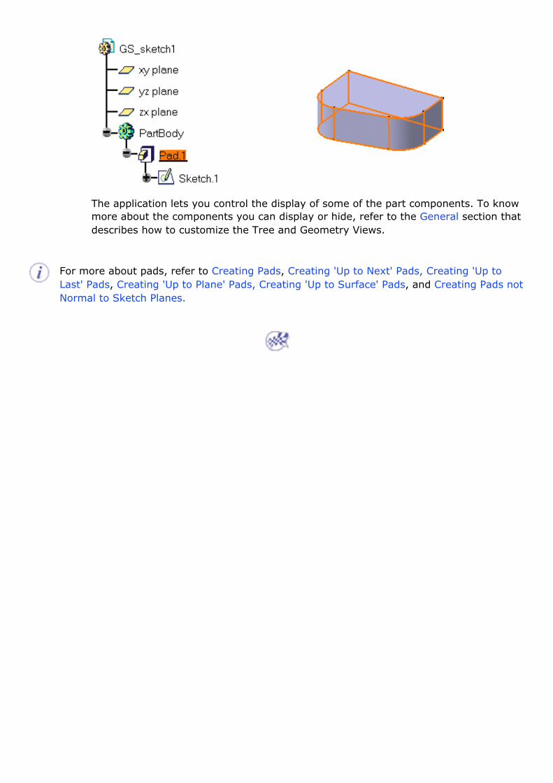
The application lets you control the display of some of the part components. To know more about the components you can display or hide, refer to the General section that describes how to customize the Tree and Geometry Views.
For more about pads, refer to Creating Pads, Creating 'Up to Next' Pads, Creating 'Up to Last' Pads, Creating 'Up to Plane' Pads, Creating 'Up to Surface' Pads, and Creating Pads not Normal to Sketch Planes.

Drafting a Face This task shows you how to draft a face.
1. Click Draft Angle . The Draft Definition dialog box appears. The application displays the default pulling direction on the part.
2. Select the face as shown by the arrow as the face to be drafted. The application detects all the faces to be drafted. The selected face is now in dark red whereas the other faces are in a lighter red.
3. Click the Selection field of the Neutral Element frame and select the upper face. The neutral element is now displayed in blue and the neutral curve is in pink.
4. Enter 9 degrees in the Angle field.
5. Click OK. The part is drafted:

For more about drafts, refer to Creating Basic Drafts, and Creating Drafts with Parting Elements.

Filleting an EdgeThis task shows you how to use one of the fillet commands designed to fillet edges.
1. Click Edge Fillet . The Edge Fillet Definition dialog box appears. It contains default values.
2. Select the edge to be filleted, that is, to be rounded.
The icon now available after the Objects to fillet field lets you edit the list of the objects to be filleted. For more information about that capability, refer to Editing a List of Elements.
Clicking Preview lets you see what the default fillet would look like.
3. Enter 7 mm as the new radius value and click OK.
Here is your part:

For more about fillets, refer to Creating Edge Fillets, Creating Face-Face Fillets, Creating Tritangent Fillets, and Creating Variable Radius Fillets.
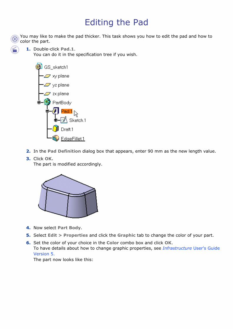
Editing the Pad You may like to make the pad thicker. This task shows you how to edit the pad and how to color the part. 1. Double-click Pad.1.
You can do it in the specification tree if you wish.
2. In the Pad Definition dialog box that appears, enter 90 mm as the new length value.
3. Click OK. The part is modified accordingly.
4. Now select Part Body.
5. Select Edit > Properties and click the Graphic tab to change the color of your part.
6. Set the color of your choice in the Color combo box and click OK. To have details about how to change graphic properties, see Infrastructure User's Guide Version 5. The part now looks like this:


Mirroring the Part This task shows you how to duplicate the part using the Mirror functionality.
1. Select the reference face you need to duplicate the part. Select the face as shown:
2. Click Mirror . The name of this face appears in the Mirroring element field.
3. Click OK. The part is mirrored and the specification tree indicates this operation.
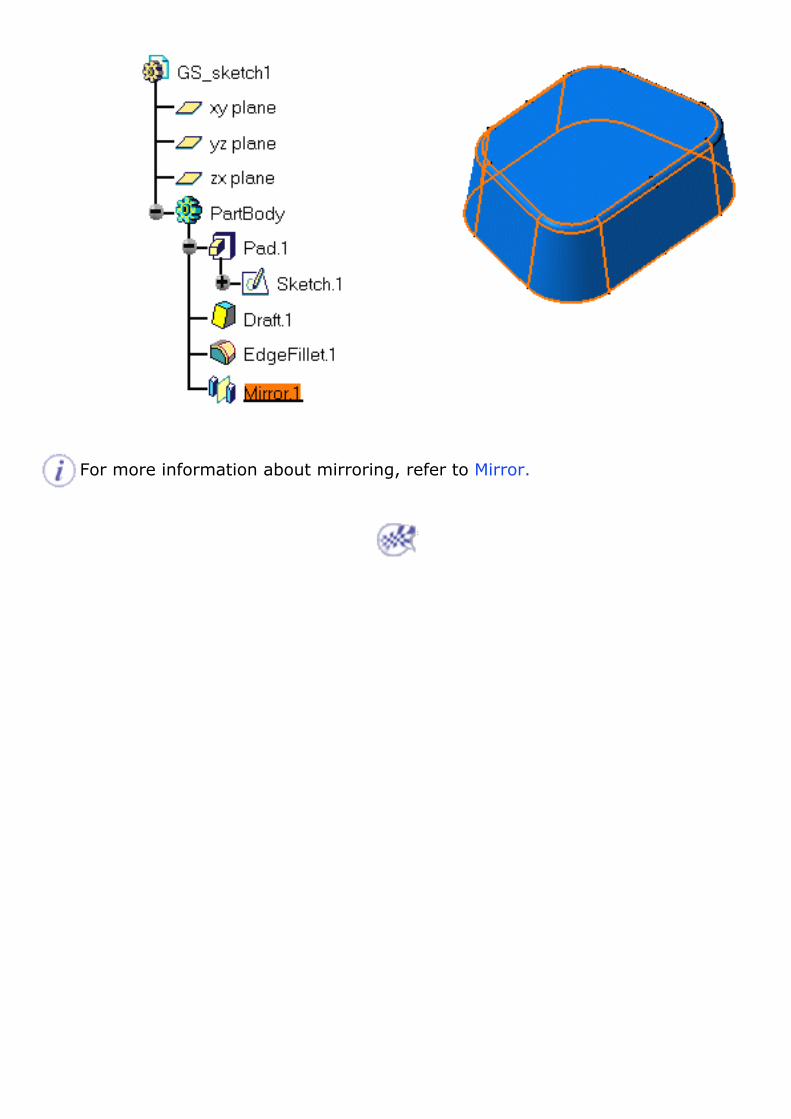
For more information about mirroring, refer to Mirror.

Sketching a Circle from a Face In this task, you will learn how to: ● sketch a circle on an existing face
● use this circle in order to create a pocket
1. Select the upper face to define the working plane.
2. Click Sketch to enter the Sketcher workbench.
3. Once in the Sketcher workbench, click Circle to create a basic circle.
4. Click the circle center in the middle of the face and drag the cursor to sketch the circle.
5. Click once you are satisfied with the size of the circle.
6. Click Exit workbench to return to the 3D world. This is your part:
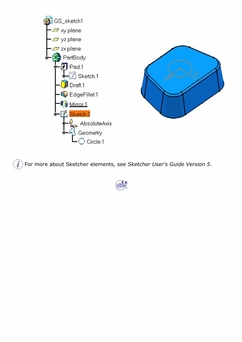
For more about Sketcher elements, see Sketcher User's Guide Version 5.
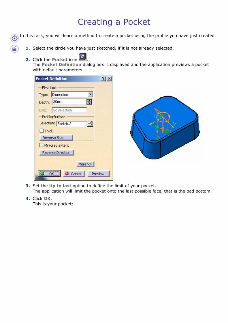
Creating a Pocket In this task, you will learn a method to create a pocket using the profile you have just created.
1. Select the circle you have just sketched, if it is not already selected.
2. Click the Pocket icon . The Pocket Definition dialog box is displayed and the application previews a pocket with default parameters.
3. Set the Up to last option to define the limit of your pocket. The application will limit the pocket onto the last possible face, that is the pad bottom.
4. Click OK. This is your pocket:

For more about pockets, see Creating Pockets.

Shelling the Part Towards the end of the scenario, you will learn how to shell the part.
1. Select the bottom face of the part.
2. Click the Shell icon . The selected face turns purple and the Shell Definition dialog box appears.
3. Enter 5mm as the inner thickness value.
4. Click OK to shell the part. You have defined a positive value, which means that you are going to obtain a thin part thickness.
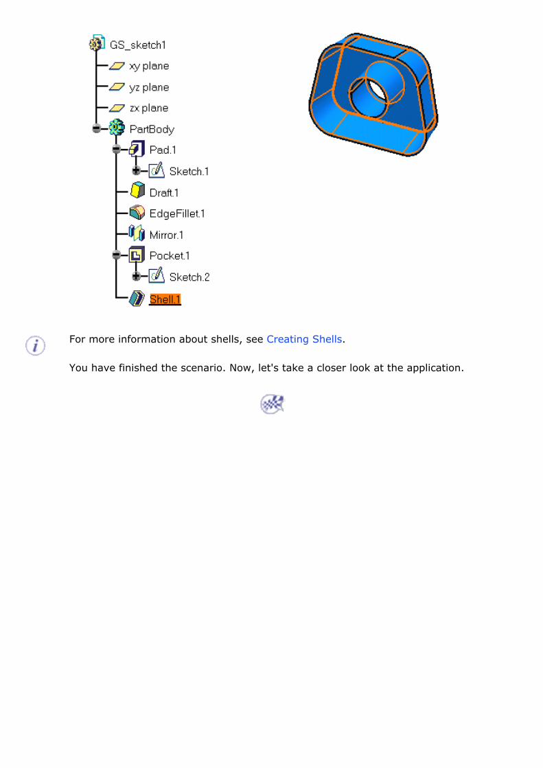
For more information about shells, see Creating Shells.
You have finished the scenario. Now, let's take a closer look at the application.

User Tasks
The basic tasks you can perform in the Part Design workbench are mainly the creation of features and surfaces you use to create your part. To create features you sometimes sketch profiles first or use existing features.
This section explains and illustrates how to create various kinds of features and surfaces. The table below lists the information you can find.
Opening a New CATPart Document Sketch-Based Features
Dress-Up Features Surface-Based Features Transformation Features
Reference Elements Modifying Parts
Setting Constraints Replacing Elements
Displaying and Editing Properties Handling Parts Hybrid Design
Associating Bodies Using Tools
Measuring Elements Using PowerCopies
Reusing your Design Optimizing Part Design Application Managing User-Defined Features
Managing Part and Assembly Templates

Opening a New CATPart Document This task shows you how to open a new CATPart document.
1. Select File > New (or click New ). The New dialog box is displayed, allowing you to choose the type of document you need.
2. Select Part from the List of Types field.
3. Click OK.
Customized Session The New Part dialog appears if your session is configured as explained in the Customizing chapter of this guide. For more information, refer to the documentation related to the Part Document tab.
4. Enter the name you want to assign to the part if the default one does not satisfy you.
5. Select the options you need for your design environment.
Hybrid Design If you select Enable hybrid design, the capability then applies to all the bodies you will create in your CATIA session (and not only to the new CATPart document you are opening). As a consequence, if your session contains CATPart documents already including traditional bodies, the new bodies you will create in these documents will possibly include wireframe and surface elements.
To facilitate your design, we recommend you never change your preferences during your session.
6. Click OK to validate your options and close the New Part dialog box. The Part Design workbench is loaded and an empty CATPart document opens.
If the New Part dialog box does not appear, the Part Design workbench is immediately loaded and an empty CATPart document opens.

The Part Design workbench document is divided into:
�❍ Specification tree
�❍ Geometry area
�❍ Specific toolbars: for information, refer to Workbench Description.
A number of contextual commands are available in the specification tree and in the geometry. Remember that these commands can also be accessed from the menu bar.
You will notice that the application provides three planes to let you start your design. Actually, designing a part from scratch first require designing a sketch. Sketching profiles is performed in the Sketcher workbench which is fully integrated into Part
Design. To open it, just click the Sketcher icon and select the work plane of your choice.
The Sketcher workbench then provides a large number of tools allowing you to sketch the profiles you need. For more information, refer to the Sketcher User's Guide.


Sketch-Based Features
Features are entities you combine to make up your part. The features presented here are obtained by applying commands on initial profiles created in the Sketcher workbench (See Sketcher User's Guide) or in the Generative Shape Design workbench (See Generative Shape Design User's Guide) as well as surfaces.
Some operations consist in adding material, others in removing material. In this section, you will learn how to create the following features:
Create a Pad: Click this icon, select the profile to be extruded and enter
the parameters you need in the dialog box. Using the Sub-elements of a Sketch: right-click the Selection field from the Pad or Pocket dialog box and select Go to Profile Definition to display the Profile Definition dialog box.
Create an 'Up to Next' Pad: Click this icon, select the profile to be extruded, set the Type option to Up to next and enter the parameters you need in the dialog box.
Create an 'Up to Last' Pad: Click this icon, select the profile to be extruded, set the Type option to Up to last and enter the parameters you need in the dialog box.
Create an 'Up to Plane' Pad: Click this icon, select the profile to be extruded, enter the parameters you need, set the Type option to `Up to plane' in the dialog box and select the required plane.
Create an 'Up to Surface' Pad: Click this icon, select the profile to be extruded, enter the parameters you need, set the Type option to Up to surface in the dialog box and select the required surface.
Create a Pad from a Surface: Click this icon, select the surface to be extruded and enter the parameters you need.
Create a Pad not Normal to Sketch Plane: Click this icon, select the profile to be extruded, expand the dialog box, enter the required parameters, define a new reference for the extrusion direction.
Create a Multi-Pad: Click this icon, select the sketch to be extruded and specify a length value for each domain.Create a Drafted Filleted Pad: Click this icon, select the profile to be extruded and enter the parameters you need in the dialog box.
Create a Pocket: Click this icon, select the profile and enter the parameters you need in the dialog box.
Create a Pocket from a Surface: Click this icon, select the surface to be extruded and enter the parameters you need.
Create a Multi-Pocket: Click this icon, select the sketch to be extruded and specify a length value for each domain.
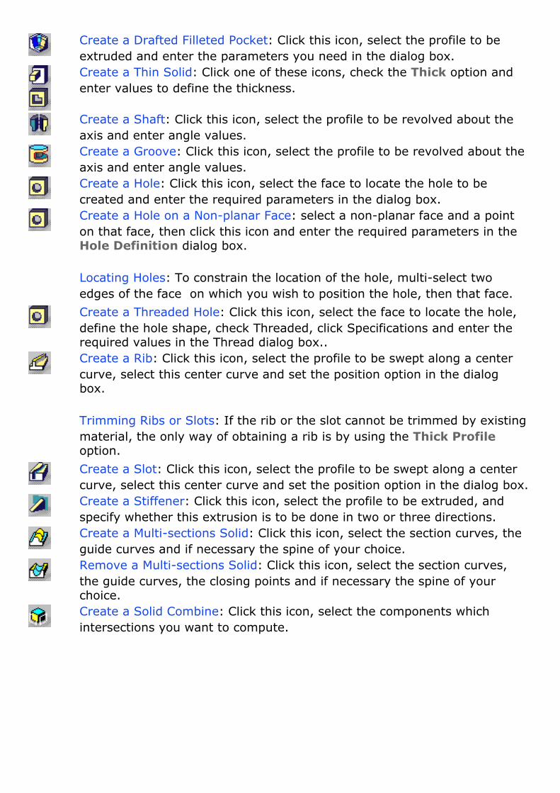
Create a Drafted Filleted Pocket: Click this icon, select the profile to be extruded and enter the parameters you need in the dialog box.
Create a Thin Solid: Click one of these icons, check the Thick option and enter values to define the thickness.
Create a Shaft: Click this icon, select the profile to be revolved about the axis and enter angle values.
Create a Groove: Click this icon, select the profile to be revolved about the axis and enter angle values.
Create a Hole: Click this icon, select the face to locate the hole to be created and enter the required parameters in the dialog box.Create a Hole on a Non-planar Face: select a non-planar face and a point on that face, then click this icon and enter the required parameters in the Hole Definition dialog box.
Locating Holes: To constrain the location of the hole, multi-select two edges of the face on which you wish to position the hole, then that face.
Create a Threaded Hole: Click this icon, select the face to locate the hole, define the hole shape, check Threaded, click Specifications and enter the required values in the Thread dialog box..
Create a Rib: Click this icon, select the profile to be swept along a center curve, select this center curve and set the position option in the dialog box.
Trimming Ribs or Slots: If the rib or the slot cannot be trimmed by existing material, the only way of obtaining a rib is by using the Thick Profile option.
Create a Slot: Click this icon, select the profile to be swept along a center curve, select this center curve and set the position option in the dialog box.
Create a Stiffener: Click this icon, select the profile to be extruded, and specify whether this extrusion is to be done in two or three directions.Create a Multi-sections Solid: Click this icon, select the section curves, the guide curves and if necessary the spine of your choice.Remove a Multi-sections Solid: Click this icon, select the section curves, the guide curves, the closing points and if necessary the spine of your choice.Create a Solid Combine: Click this icon, select the components which intersections you want to compute.

How Sketches are Located in the Specification Tree
Up to Part Design Version 5 release 14 the sketches used for creating sketch-based features were located directly below the features in the specification tree. Now, to improve the visibility of your design process this behavior has changed: new rules define the location of sketch entities in the specification tree. The How Sketches are Located in the Specification Tree section covers this new behavior.
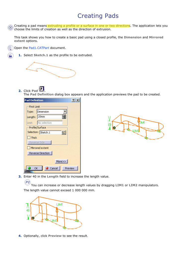
Creating Pads Creating a pad means extruding a profile or a surface in one or two directions. The application lets you choose the limits of creation as well as the direction of extrusion.
This task shows you how to create a basic pad using a closed profile, the Dimension and Mirrored extent options.
Open the Pad1.CATPart document.
1. Select Sketch.1 as the profile to be extruded.
2. Click Pad . The Pad Definition dialog box appears and the application previews the pad to be created.
3. Enter 40 in the Length field to increase the length value.
You can increase or decrease length values by dragging LIM1 or LIM2 manipulators.
The length value cannot exceed 1 000 000 mm.
4. Optionally, click Preview to see the result.
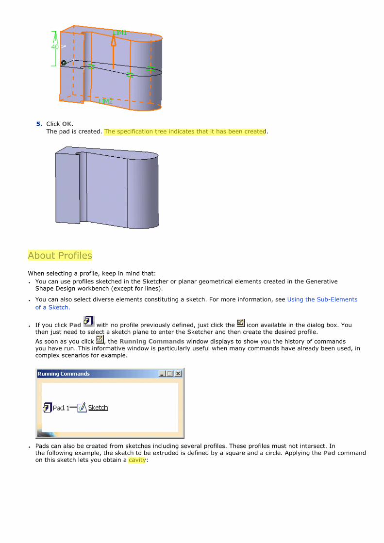
5. Click OK. The pad is created. The specification tree indicates that it has been created.
About Profiles
When selecting a profile, keep in mind that:● You can use profiles sketched in the Sketcher or planar geometrical elements created in the Generative
Shape Design workbench (except for lines).
● You can also select diverse elements constituting a sketch. For more information, see Using the Sub-Elements of a Sketch.
● If you click Pad with no profile previously defined, just click the icon available in the dialog box. You then just need to select a sketch plane to enter the Sketcher and then create the desired profile.
As soon as you click , the Running Commands window displays to show you the history of commands you have run. This informative window is particularly useful when many commands have already been used, in complex scenarios for example.
● Pads can also be created from sketches including several profiles. These profiles must not intersect. In the following example, the sketch to be extruded is defined by a square and a circle. Applying the Pad command on this sketch lets you obtain a cavity:

Preview Result
You can select Generative Shape Design surfaces, non-planar faces and even CATIA V4 surfaces. For more information, refer to Creating Pads or Pockets from Surfaces.�❍ By default, if you extrude a profile, the application extrudes normal to the plane used to create the profile. To
see how to change the extrusion direction, refer to Creating Pads not Normal to Sketch Plane.
�❍ If you extrude a surface (for example created in the Generative Shape Design workbench), you need to select an element defining the direction because there is no default direction.
Changing Profiles
If you are not satisfied with the profile you selected, note that you can:
�❍ click the Selection field and select another sketch.
�❍ Click Sketch : this opens the Sketcher. You can then edit the profile. Once you have done your modifications, you just need to quit the Sketcher. The Pad dialog box then reappears to let you finish your design.
�❍ use any of these creation contextual commands available from the Selection field:■ Create Sketch: launches the Sketcher after selecting any plane, and lets you sketch the profile you
need as explained in the Sketcher User's Guide.
■ Create Join: joins surfaces or curves. See Joining Surfaces or Curves.
■ Create Extract: generates separate elements from non-connex sub-elements. See Extracting Geometry.
If you have chosen to work in a hybrid design environment, the geometrical elements created on the fly via the contextual commands mentioned above are aggregated into sketch-based features.
Limits
You will notice that by default, the application specifies the length of your pad (Type= Dimension option). But you can use the following options too: ● Up to Next
● Up to Last
● Up to Plane
● Up to Surface
● If you set the Up to Plane or Up to Surface option, contextual commands creating new planes or surfaces you may need are then available from the Limit field:�❍ Create Plane: see Creating Planes
�❍ XY Plane: the XY plane of the current coordinate system origin (0,0,0) becomes the limit.
�❍ YZ Plane: the YZ plane of the current coordinate system origin (0,0,0) becomes the limit.
�❍ ZX Plane: the ZX plane of the current coordinate system origin (0,0,0) becomes the limit.

�❍ Create Join: joins surfaces or curves. See Joining Surfaces or Curves.
�❍ Create Extrapol: extrapolates surface boundaries. See Extrapolating Surfaces.
If you create any of these elements, the application then displays the corresponding icon in front of the field. Clicking this icon enables you to edit the element.
If you have chosen to work in a hybrid design environment, the elements created on the fly via the contextual commands mentioned above are aggregated into sketch-based features.
Options
The following pad creation options are available:● Thick: adds thickness to both sides of your profile. To know how to use it, refer to Creating Thin Solids.
● Reverse side: applies for open profiles only. This option lets you choose which side of the profile is to be
extruded. When designing thin solids, the option is meaningless.
● Mirrored extent: extrudes the profile in the opposite direction using the same length value. If you wish to define another length for this direction, you do not have to click the Mirrored extent button. Just click the More button and define the second limit.
A Few Notes About Pads
Keep in mind the following:● Before clicking Pad, ensure that the profile to be used is not tangent with itself.
● The application allows you to create pads from open profiles provided existing geometry can trim the pads. The pad below has been created from an open profile which both endpoints were stretched onto the inner vertical faces of the hexagon. The option used for Limit 1 is Up to next. The inner bottom face of the hexagon then stops the extrusion. Conversely, the Up to next option could not be used for Limit2.
Preview Result
However, if the application can generate an intersection between both profile endpoints, it produces a pad as in the following example. The profile chosen is an arc of circle. Although no existing geometry can trim the pad to be created, the application succeeds in generating a pad.
Profile Result
Using the Sub-Elements of a Sketch
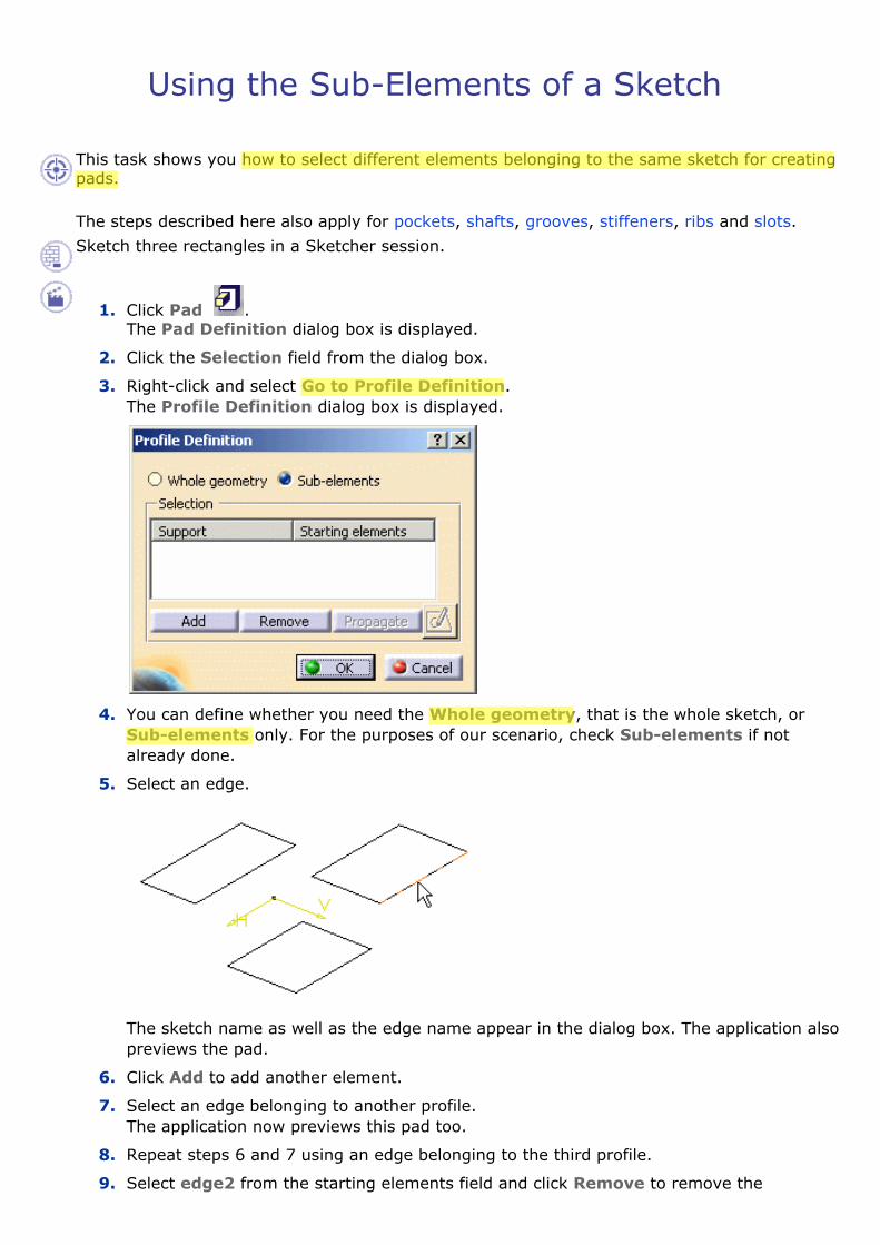
This task shows you how to select different elements belonging to the same sketch for creating pads.
The steps described here also apply for pockets, shafts, grooves, stiffeners, ribs and slots. Sketch three rectangles in a Sketcher session.
1. Click Pad . The Pad Definition dialog box is displayed.
2. Click the Selection field from the dialog box.
3. Right-click and select Go to Profile Definition. The Profile Definition dialog box is displayed.
4. You can define whether you need the Whole geometry, that is the whole sketch, or Sub-elements only. For the purposes of our scenario, check Sub-elements if not already done.
5. Select an edge.
The sketch name as well as the edge name appear in the dialog box. The application also previews the pad.
6. Click Add to add another element.
7. Select an edge belonging to another profile. The application now previews this pad too.
8. Repeat steps 6 and 7 using an edge belonging to the third profile.
9. Select edge2 from the starting elements field and click Remove to remove the
associated profile from the selection.
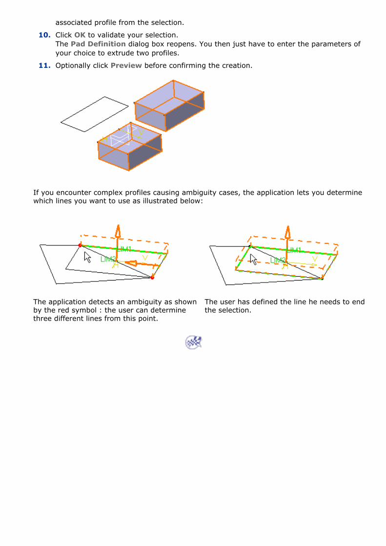
10. Click OK to validate your selection. The Pad Definition dialog box reopens. You then just have to enter the parameters of your choice to extrude two profiles.
11. Optionally click Preview before confirming the creation.
If you encounter complex profiles causing ambiguity cases, the application lets you determine which lines you want to use as illustrated below:
The application detects an ambiguity as shown by the red symbol : the user can determine three different lines from this point.
The user has defined the line he needs to end the selection.
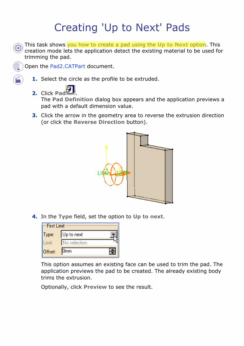
Creating 'Up to Next' PadsThis task shows you how to create a pad using the Up to Next option. This creation mode lets the application detect the existing material to be used for trimming the pad.
Open the Pad2.CATPart document.
1. Select the circle as the profile to be extruded.
2. Click Pad . The Pad Definition dialog box appears and the application previews a pad with a default dimension value.
3. Click the arrow in the geometry area to reverse the extrusion direction (or click the Reverse Direction button).
4. In the Type field, set the option to Up to next.
This option assumes an existing face can be used to trim the pad. The application previews the pad to be created. The already existing body trims the extrusion.
Optionally, click Preview to see the result.

5. Click OK. The pad is created. The specification tree indicates this creation.
By default, the application extrudes normal to the plane used to create the profile. To learn how to change the direction, refer to Creating Pads not Normal to Sketch Plane .
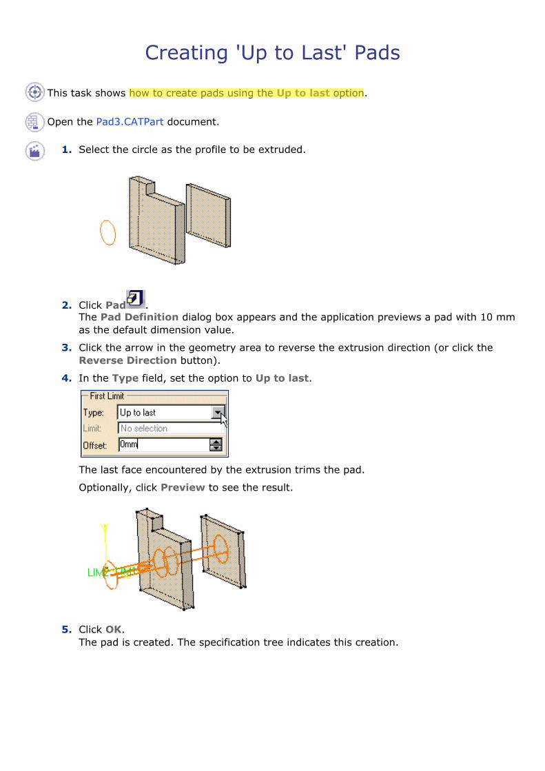
Creating 'Up to Last' Pads
This task shows how to create pads using the Up to last option.
Open the Pad3.CATPart document.
1. Select the circle as the profile to be extruded.
2. Click Pad . The Pad Definition dialog box appears and the application previews a pad with 10 mm as the default dimension value.
3. Click the arrow in the geometry area to reverse the extrusion direction (or click the Reverse Direction button).
4. In the Type field, set the option to Up to last.
The last face encountered by the extrusion trims the pad.
Optionally, click Preview to see the result.
5. Click OK. The pad is created. The specification tree indicates this creation.
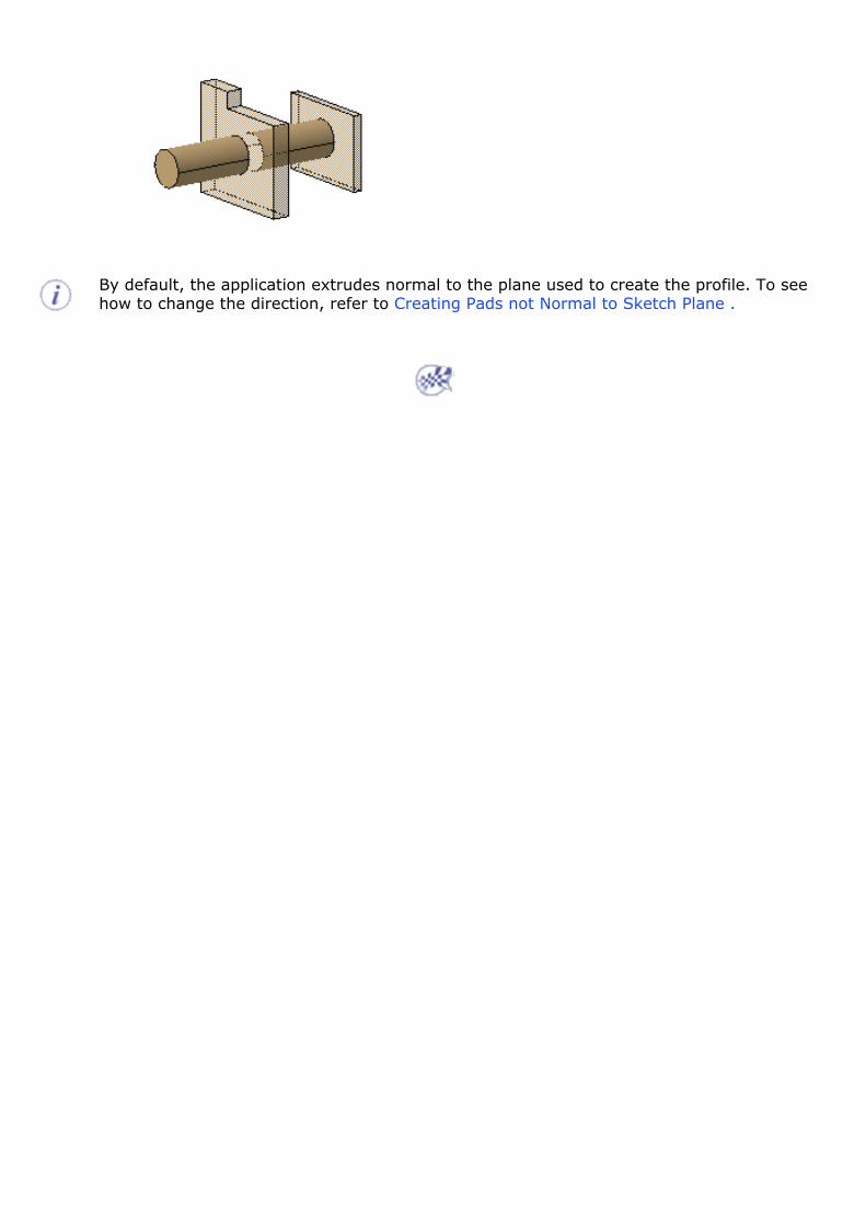
By default, the application extrudes normal to the plane used to create the profile. To see how to change the direction, refer to Creating Pads not Normal to Sketch Plane .

Creating 'Up to Plane' Pads This task shows how to create pads using the Up to plane option.
Open the Pad4.CATPart document.
1. Select the profile to be extruded.
2. Click Pad . The Pad Definition dialog box appears and the application previews a pad with 10 mm as the default dimension value.
3. In the Type field, set the Type option to Up to plane.
4. Select Plane.1. The application previews the pad to be created. The plane trims the extrusion. An Offset option is now available.
Contextual commands creating the planes you need are available from the Limit field:
�❍ Create Plane: see Creating Planes
�❍ XY Plane: the XY plane of the current coordinate system origin (0,0,0) becomes the trimming element.
�❍ YZ Plane: the YZ plane of the current coordinate system origin (0,0,0) becomes the trimming element.
�❍ ZX Plane: the ZX plane of the current coordinate system origin (0,0,0) becomes the trimming element.
If you create any of these elements, the application then displays the plane icon in front of the Limit field. Clicking this icon enables you to edit the element.

5. Enter -20 as the offset value. This offset is the distance between the plane and the top face of the pad to be created. Optionally click Preview to see the result.
6. Click OK. The pad is created. The specification tree indicates this creation.
By default, the application extrudes normal to the plane used to create the profile. To see how to change the direction, refer to Pad not Normal to Sketch Plane .

Creating 'Up to Surface' Pads
This task shows you how to create pads using the Up to surface option.
Open the Pad5.CATPart document.
1. Select the profile to be extruded.
2. Click Pad . The Pad Definition dialog box appears and the application previews a pad with a default dimension value.
3. In the Type field, set the Type option to Up to surface.
4. Select the vertical circular face. This face belongs to the same body as the existing pad. Using the Up to surface option, you can select a face belonging to the same body as the sketch or a face belonging to Part Body. The face trims the extrusion.
Contextual Commands
Contextual commands creating the surfaces you need are available from the Limit field:
�❍ Create Join: joins surfaces or curves. See Joining Surfaces or Curves.
�❍ Create Extrapol: extrapolates surface boundaries or curves. See Extrapolating Surfaces and Extrapolating Curves.
If you create any of these elements, the application then displays the join or the extrapol icon in front of the Limit field. Clicking this icon enables you to edit the element.
5. An Offset option is available in the dialog box. Enter -30 as the offset value. This offset is the distance between the surface and the top face of the pad to be created.
Optionally click Preview to see the result.
6. Click OK. The pad is created. The specification tree indicates this creation.
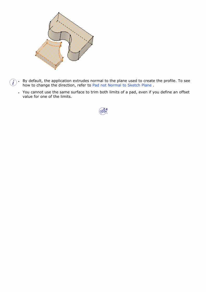
● By default, the application extrudes normal to the plane used to create the profile. To see
how to change the direction, refer to Pad not Normal to Sketch Plane .
● You cannot use the same surface to trim both limits of a pad, even if you define an offset value for one of the limits.

Creating Pads or Pockets from Surfaces
This task explains how to extrude surfaces in any direction. The scenario below shows you how to create a pad, but the method and options described are also valid for creating pockets.
Open the ThickSurface.CATPart document.
1. Select Extrude.1 as the surface to be extruded. The different surfaces you can select are:
�❍ surfaces created in the Generative Shape Design workbench
�❍ CATIA Version 4 surfaces
�❍ non-planar faces.
2. Click Pad . The Pad Definition dialog box appears. You need to define an extrusion direction. To do so, either you select a geometric element or set the Up to Plane limit and select the plane of your choice. In that case, the direction will be given by the normal to that plane (for more, see pockets).
3. Click the Reference field and select Plane.1 as the plane defining the extrusion direction. The direction is the normal to the plane.
Make sure that the surface to be extruded is not tangent to the extrusion direction nor to the plane.
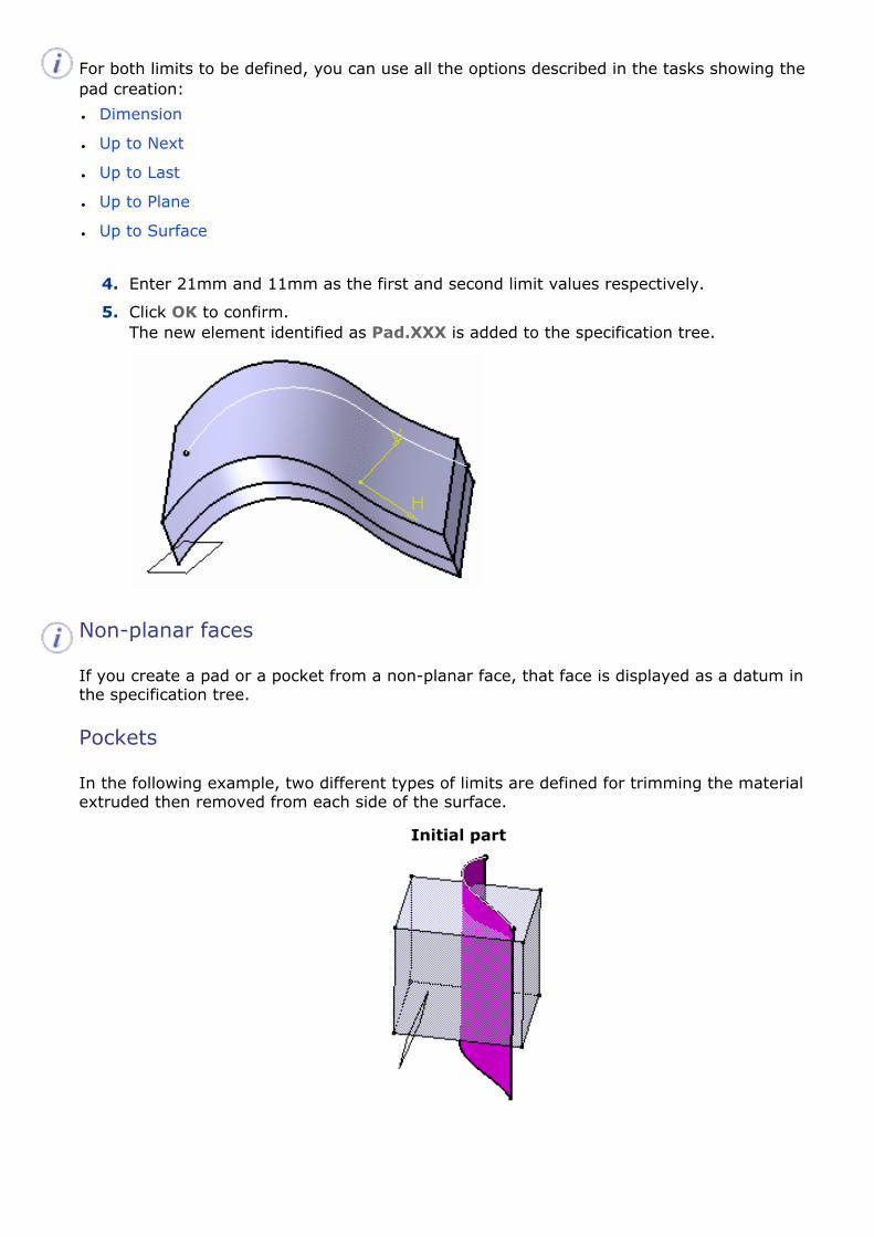
For both limits to be defined, you can use all the options described in the tasks showing the pad creation:
● Dimension
● Up to Next
● Up to Last
● Up to Plane
● Up to Surface
4. Enter 21mm and 11mm as the first and second limit values respectively.
5. Click OK to confirm. The new element identified as Pad.XXX is added to the specification tree.
Non-planar faces
If you create a pad or a pocket from a non-planar face, that face is displayed as a datum in the specification tree.
Pockets
In the following example, two different types of limits are defined for trimming the material extruded then removed from each side of the surface.
Initial part
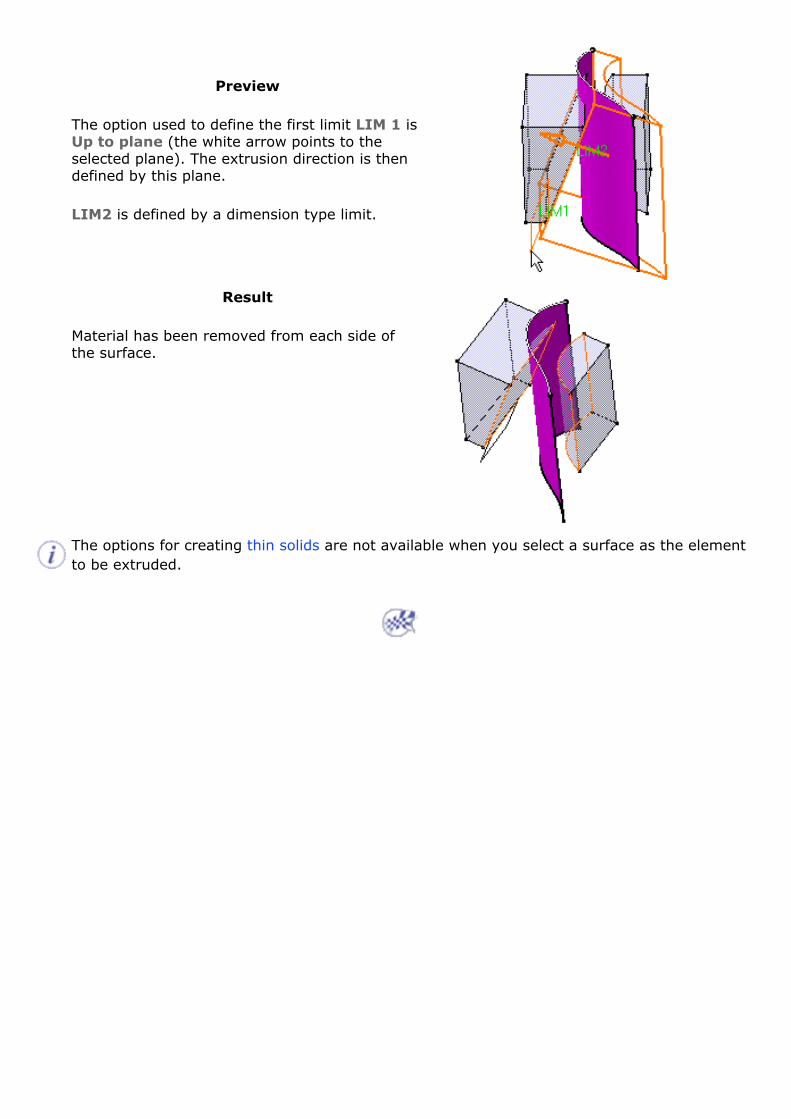
Preview
The option used to define the first limit LIM 1 is Up to plane (the white arrow points to the selected plane). The extrusion direction is then defined by this plane.
LIM2 is defined by a dimension type limit.
Result
Material has been removed from each side of the surface.
The options for creating thin solids are not available when you select a surface as the element to be extruded.
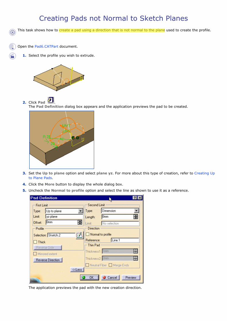
Creating Pads not Normal to Sketch Planes This task shows how to create a pad using a direction that is not normal to the plane used to create the profile.
Open the Pad6.CATPart document.
1. Select the profile you wish to extrude.
2. Click Pad . The Pad Definition dialog box appears and the application previews the pad to be created.
3. Set the Up to plane option and select plane yz. For more about this type of creation, refer to Creating Up to Plane Pads.
4. Click the More button to display the whole dialog box.
5. Uncheck the Normal to profile option and select the line as shown to use it as a reference.
The application previews the pad with the new creation direction.
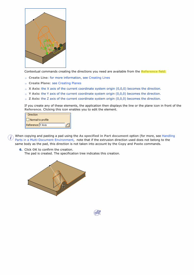
Contextual commands creating the directions you need are available from the Reference field:
�❍ Create Line: for more information, see Creating Lines
�❍ Create Plane: see Creating Planes
�❍ X Axis: the X axis of the current coordinate system origin (0,0,0) becomes the direction.
�❍ Y Axis: the Y axis of the current coordinate system origin (0,0,0) becomes the direction.
�❍ Z Axis: the Z axis of the current coordinate system origin (0,0,0) becomes the direction.
If you create any of these elements, the application then displays the line or the plane icon in front of the Reference. Clicking this icon enables you to edit the element.
When copying and pasting a pad using the As specified in Part document option (for more, see Handling Parts in a Multi-Document Environment, note that if the extrusion direction used does not belong to the same body as the pad, this direction is not taken into account by the Copy and Paste commands.
6. Click OK to confirm the creation. The pad is created. The specification tree indicates this creation.

Creating Multi-Pads This task shows you how to extrude multiple profiles belonging to a same sketch using different length values. The multi-pad capability lets you do this at one time. At the end of the task you will see how to edit the resulting feature. ● Creating a Multi-Pad
● Editing a Multi-Pad�❍ Adding an Extrusion Domain
�❍ Deleting an Extrusion Domain
Open the Pad1.CATPart document.
Creating a Multi-Pad
1. Click Multi-Pad .
2. Select Sketch.2 that contains the profiles to be extruded. Note that all profiles must be closed and must not intersect. In case a profile would be open, the application would not take it into account. The Multi-Pad Definition dialog box appears and the profiles are highlighted in green. For each of them, you can drag associated manipulators to define the extrusion value.
The red arrow normal to the sketch indicates the proposed extrusion direction. To reverse it, you just need to click it.
The Multi- Pad Definition dialog box displays the number of domains to be extruded. In our example, the application has detected seven extrusions to perform, as indicated in the Domains section.

3. Select Extrusion domain.1 from the dialog box. Extrusion domain.1 now appears in blue in the geometry area.
4. Specify the length by entering a value. For example, enter 10mm.
5. You need to repeat the operation for each extrusion domain by entering the value of your choice. For example, select Extrusion domain.2 and Extrusion domain.7 and enter 30mm and 40mm respectively.
For complex sketches, the Preview button proves to be quite useful.
6. Note that you can multi-select extrusion domains from the list before defining a common length: multi-select Extrusion domain.3, Extrusion domain.4, Extrusion domain.5 and Extrusion domain.6, then enter 50 as the common length value.
One length value is now defined for each profile of Sketch.2.
7. Click More>> to expand the dialog box.
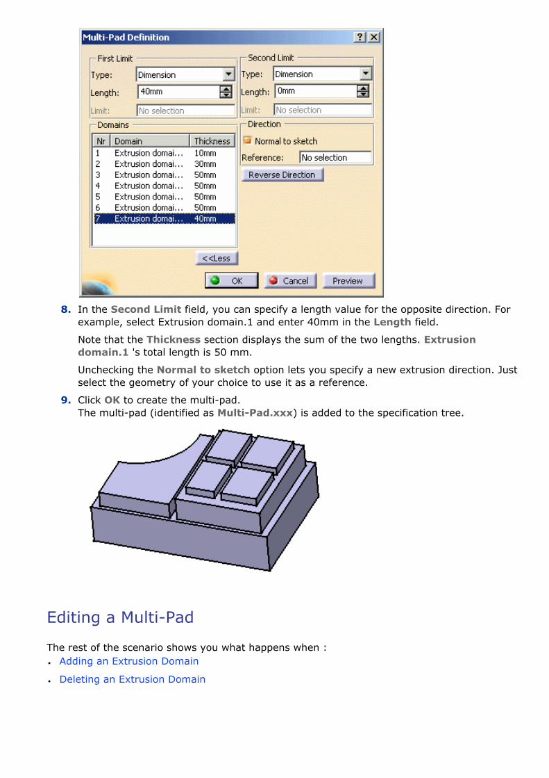
8. In the Second Limit field, you can specify a length value for the opposite direction. For example, select Extrusion domain.1 and enter 40mm in the Length field.
Note that the Thickness section displays the sum of the two lengths. Extrusion domain.1 's total length is 50 mm.
Unchecking the Normal to sketch option lets you specify a new extrusion direction. Just select the geometry of your choice to use it as a reference.
9. Click OK to create the multi-pad. The multi-pad (identified as Multi-Pad.xxx) is added to the specification tree.
Editing a Multi-Pad
The rest of the scenario shows you what happens when :● Adding an Extrusion Domain
● Deleting an Extrusion Domain

Adding an Extrusion Domain
Example 1: the new profile is sketched outside existing extrusion domains
10. Double-click Sketch.2 to edit it: for example, sketch a closed profile outside Extrusion domain.1.
11. Quit the Sketcher. A warning message informs you that the application has detected that the initial geometry has been modified. Close the window.
12. Double-click MultiPad.1 . The Feature Definition Error window displays, providing the details of the modification.
13. Click OK to close the window. The Multi-Pocket Definition dialog box reappears. The new extrusion domain Extrusion domain.8 is indicated.
14. Select it and define the value of your choice.
15. Click OK to confirm. Multi-pad.1 is now composed of eight pads.
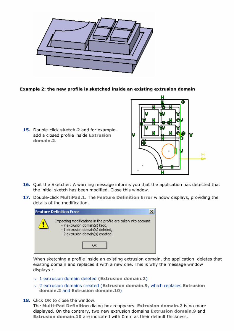
Example 2: the new profile is sketched inside an existing extrusion domain
15. Double-click sketch.2 and for example, add a closed profile inside Extrusion domain.2.
16. Quit the Sketcher. A warning message informs you that the application has detected that the initial sketch has been modified. Close this window.
17. Double-click MultiPad.1. The Feature Definition Error window displays, providing the details of the modification.
When sketching a profile inside an existing extrusion domain, the application deletes that existing domain and replaces it with a new one. This is why the message window displays :
�❍ 1 extrusion domain deleted (Extrusion domain.2)
�❍ 2 extrusion domains created (Extrusion domain.9, which replaces Extrusion domain.2 and Extrusion domain.10)
18. Click OK to close the window. The Multi-Pad Definition dialog box reappears. Extrusion domain.2 is no more displayed. On the contrary, two new extrusion domains Extrusion domain.9 and Extrusion domain.10 are indicated with 0mm as their default thickness.

19. Select Extrusion domain.9 if not already done and define 30mm as the length value.
20. Select Extrusion domain.10, that is the circle, and define 60mm as the length value.
21. Click OK to confirm. Multi-pad.1 is now composed of nine pads.
Deleting an Extrusion Domain
22. Double-click Sketch.2 and for example, delete Extrusion Domain.6.

23. Quit the Sketcher: the application has detected that the initial sketch has been modified:
24. To tackle the problem, you can:
�❍ edit or delete MultiPad.1.
�❍ or you can edit or delete Extrusion domain.6
Make sure that MultiPad.1 is selected and click the Edit button. The Feature Definition Error window displays, providing the details of the modification.
25. Click OK to close the window. The Multi-Pad Definition dialog box reappears. Only eight extrusion domains are indicated in the Domains category.
26. Click OK to confirm. The new multi-pad feature is composed of eight pads.

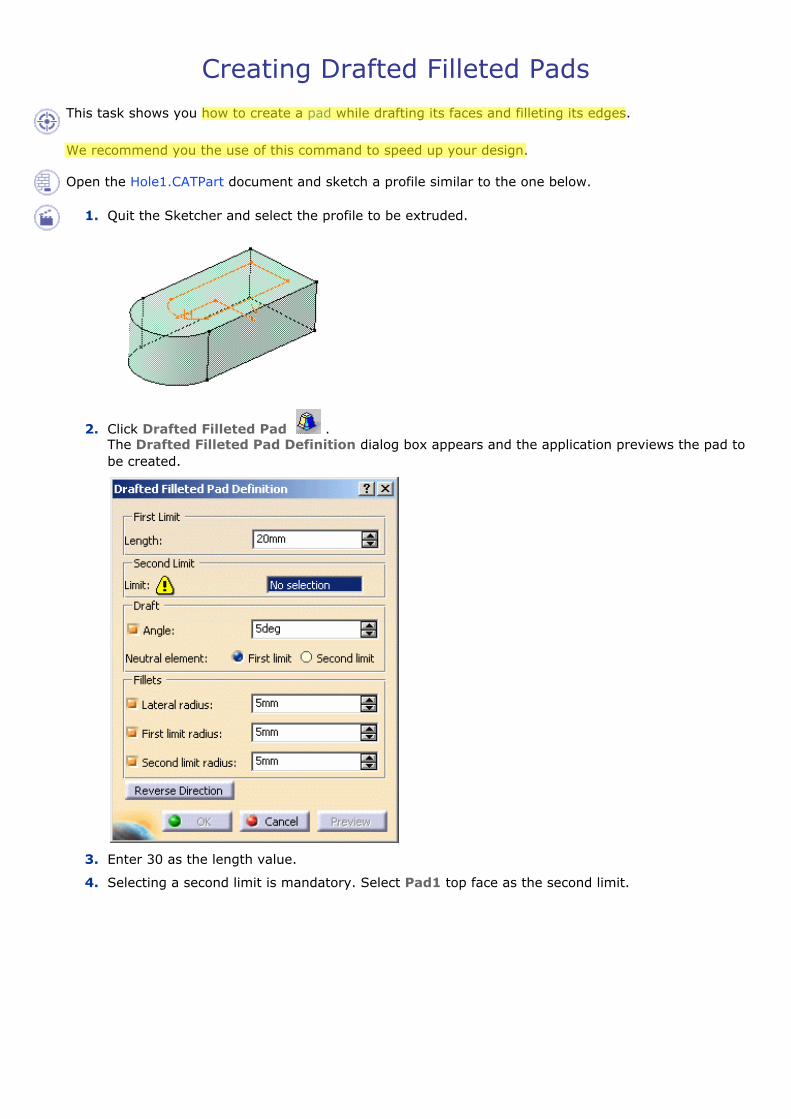
Creating Drafted Filleted Pads This task shows you how to create a pad while drafting its faces and filleting its edges.
We recommend you the use of this command to speed up your design.
Open the Hole1.CATPart document and sketch a profile similar to the one below.
1. Quit the Sketcher and select the profile to be extruded.
2. Click Drafted Filleted Pad . The Drafted Filleted Pad Definition dialog box appears and the application previews the pad to be created.
3. Enter 30 as the length value.
4. Selecting a second limit is mandatory. Select Pad1 top face as the second limit.

Note that planes can define second limits too.
5. Let's go on with the draft definition. Enter 7 as the draft angle value. Drafting faces is optional. If you do not wish to use this capability, just uncheck the Angle option.
6. Check the Second limit option to define the neutral element. So, Pad1 top face is also used as the neutral element.
7. Enter a radius value for each edge type to define the three fillets.
�❍ Lateral radius: defines the fillets on vertical edges
�❍ First limit radius: defines the round corner fillets
�❍ Second limit radius: defines the filets on the edges of the second limit.
Filleting edges is optional too. If you do not wish to use this capability, just uncheck the options.
Clicking Preview previews the pad, the draft and the fillets and display them in the specification tree. If you have deactivated the draft or fillet options, the draft or the fillets are then displayed as deactivated features in the tree, i.e. with red parentheses.
8. Click OK to create the features. If you look at the specification tree, you will note that you have created:
�❍ one pad
�❍ one draft
�❍ three fillets
This means that for edition purposes, you need to double-click the appropriate feature. This is your new part:

Creating Pockets Creating a pocket consists in extruding a profile or a surface and removing the material resulting from the extrusion. The application lets you choose the limits of creation as well as the direction of extrusion. The limits you can use are the same as those available for creating pads. To know how to use them, see Creating Up to Next Pads, Creating Up to Last Pads, Creating Up to Plane Pads, Creating Up to Surface Pads.
This task first shows you how to create a pocket, that is a cavity, in an already existing part, then you will edit this pocket to remove the material surrounding the initial profile.
Open the Pocket1.CATPart document.
1. Select the profile to extrude, that is Sketch.2.
About Profiles ● You can use profiles sketched in the Sketcher workbench or planar geometrical
elements created in the Generative Shape Design workbench (except for lines).
● You can create pockets from sketches including several closed profiles. These profiles must not intersect.
● You can select diverse elements constituting a sketch too. For more information, refer to Using the Sub-Elements of a Sketch.
● Instead of selecting profiles, you can select surfaces created in the Generative Shape Design workbench, non-planar faces and even CATIA V4. To know how to create a pocket from a surface, refer to Creating Pads or Pockets from Surfaces.
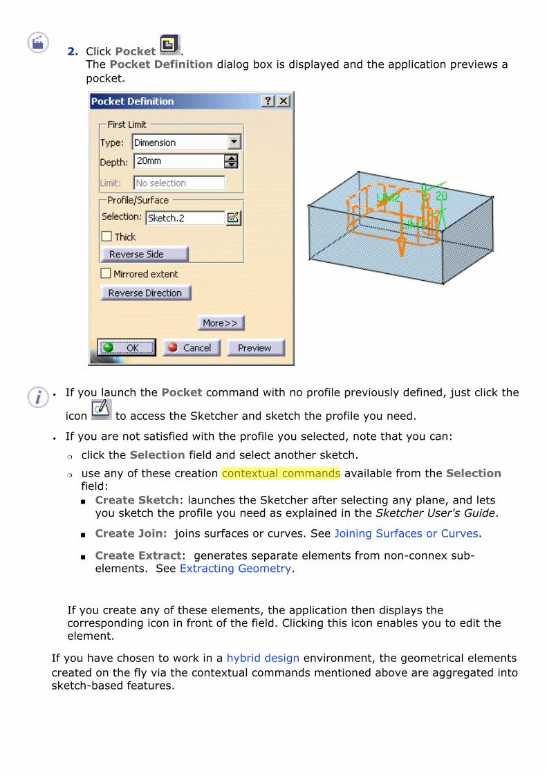
2. Click Pocket . The Pocket Definition dialog box is displayed and the application previews a pocket.
● If you launch the Pocket command with no profile previously defined, just click the
icon to access the Sketcher and sketch the profile you need.
● If you are not satisfied with the profile you selected, note that you can:
�❍ click the Selection field and select another sketch.
�❍ use any of these creation contextual commands available from the Selection field:■ Create Sketch: launches the Sketcher after selecting any plane, and lets
you sketch the profile you need as explained in the Sketcher User's Guide.
■ Create Join: joins surfaces or curves. See Joining Surfaces or Curves.
■ Create Extract: generates separate elements from non-connex sub-elements. See Extracting Geometry.
If you create any of these elements, the application then displays the corresponding icon in front of the field. Clicking this icon enables you to edit the element.
If you have chosen to work in a hybrid design environment, the geometrical elements created on the fly via the contextual commands mentioned above are aggregated into sketch-based features.

You can define a specific depth for your pocket or set one of these options: ● up to next
● up to last
● up to plane
● up to surface
If you wish to use the Up to plane or Up to surface option, you can then define an offset between the limit plane (or surface) and the bottom of the pocket. For more information, refer to Up to Surface Pad.
3. To define a specific depth, set the Type parameter to Dimension, and enter 30mm.
Alternatively, select LIM1 manipulator and drag it downwards to 30.
Clicking the icon opens the Sketcher. You can then edit the profile to modify your
pocket. Once you have done your modifications, you just need to quit the Sketcher. The Pocket dialog box reappears to let you finish your design.
About Directions
By default, if you extrude a profile, the application extrudes normal to the plane used to create the profile. To specify another direction, click the More button to display the whole Pocket Definition dialog box, uncheck the Normal to profile option and select a new creation direction in the geometry.● When copying and pasting a pocket using the As specified in Part document
option (for more, see Handling Parts in a Multi-Document Environment), note that if the extrusion direction used does not belong to the same body as the pocket, this direction is not taken into account by the Copy and Paste commands.
● If you extrude a surface (for example created in the Generative Shape Design workbench), you need to select an element defining the direction because there is no default direction.
Limits
If you set the Up to Plane or Up to Surface option, contextual commands creating new planes or surfaces you may need are then available from the Limit field:● Create Plane: see Creating Planes
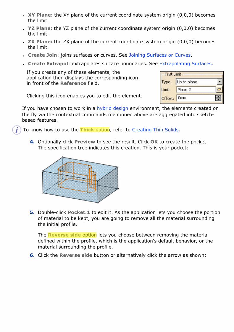
● XY Plane: the XY plane of the current coordinate system origin (0,0,0) becomes the limit.
● YZ Plane: the YZ plane of the current coordinate system origin (0,0,0) becomes the limit.
● ZX Plane: the ZX plane of the current coordinate system origin (0,0,0) becomes the limit.
● Create Join: joins surfaces or curves. See Joining Surfaces or Curves.
● Create Extrapol: extrapolates surface boundaries. See Extrapolating Surfaces.
If you create any of these elements, the application then displays the corresponding icon in front of the Reference field.
Clicking this icon enables you to edit the element.
If you have chosen to work in a hybrid design environment, the elements created on the fly via the contextual commands mentioned above are aggregated into sketch-based features.
To know how to use the Thick option, refer to Creating Thin Solids.
4. Optionally click Preview to see the result. Click OK to create the pocket. The specification tree indicates this creation. This is your pocket:
5. Double-click Pocket.1 to edit it. As the application lets you choose the portion of material to be kept, you are going to remove all the material surrounding the initial profile. The Reverse side option lets you choose between removing the material defined within the profile, which is the application's default behavior, or the material surrounding the profile.
6. Click the Reverse side button or alternatively click the arrow as shown:

The arrow now indicates the opposite direction.
7. Click OK to confirm. The application has removed the material around the profile.
A Few Notes About Pockets ● The application allows you to create pockets from open profiles provided existing
geometry can trim the pockets.
● If your insert a new body and create a pocket as the first feature of this body, the application creates material:
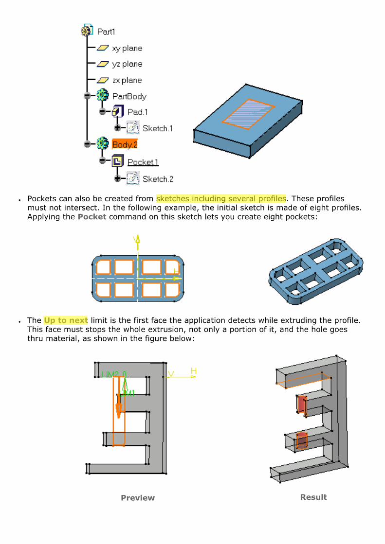
● Pockets can also be created from sketches including several profiles. These profiles must not intersect. In the following example, the initial sketch is made of eight profiles. Applying the Pocket command on this sketch lets you create eight pockets:
● The Up to next limit is the first face the application detects while extruding the profile. This face must stops the whole extrusion, not only a portion of it, and the hole goes thru material, as shown in the figure below:
Preview Result

● When using the Up to Surface option, remember that if the selected surface partly stops the extrusion, the application continues to extrude the profile until it meets a surface that can fully stop the operation.
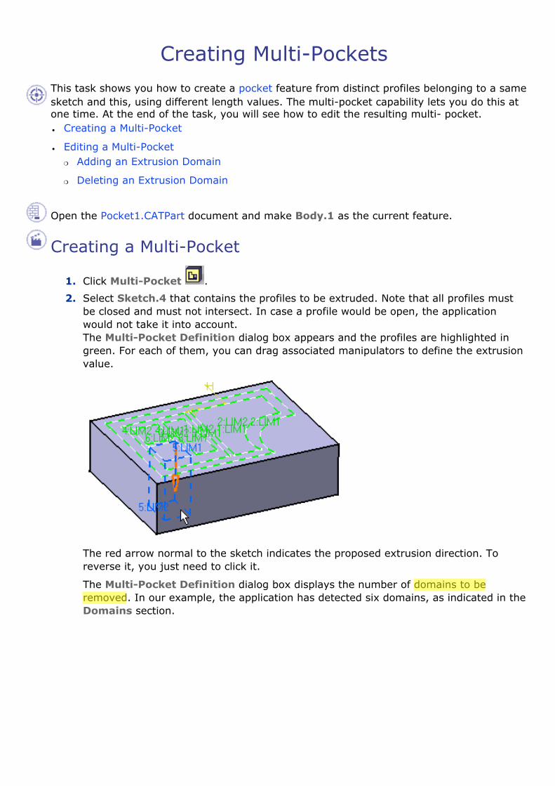
Creating Multi-Pockets This task shows you how to create a pocket feature from distinct profiles belonging to a same sketch and this, using different length values. The multi-pocket capability lets you do this at one time. At the end of the task, you will see how to edit the resulting multi- pocket.● Creating a Multi-Pocket
● Editing a Multi-Pocket�❍ Adding an Extrusion Domain
�❍ Deleting an Extrusion Domain
Open the Pocket1.CATPart document and make Body.1 as the current feature.
Creating a Multi-Pocket
1. Click Multi-Pocket .
2. Select Sketch.4 that contains the profiles to be extruded. Note that all profiles must be closed and must not intersect. In case a profile would be open, the application would not take it into account. The Multi-Pocket Definition dialog box appears and the profiles are highlighted in green. For each of them, you can drag associated manipulators to define the extrusion value.
The red arrow normal to the sketch indicates the proposed extrusion direction. To reverse it, you just need to click it.
The Multi-Pocket Definition dialog box displays the number of domains to be removed. In our example, the application has detected six domains, as indicated in the Domains section.

3. Select Extrusion domain.1 from the dialog box. Extrusion domain.1 now appears in blue in the geometry area.
4. Specify the length by entering a value. For example, enter 10mm.
5. You need to repeat the operation for each extrusion domain by entering the value of your choice. For example, select Extrusion domain.2 and Extrusion domain.6 and enter 30mm and 40mm respectively.
For complex sketches, the Preview button proves to be quite useful.
6. Note that you can multi-select extrusion domains from the list before defining a common length: multi-select Extrusion domain.3, Extrusion domain.4, and Extrusion domain.5, then enter 50 as the common length value.
7. Click More>> to expand the dialog box. In the Second Limit field, you can specify a length value for the direction opposite to the direction previously defined. Note that the Thickness section displays the sum of two lengths defined for a given extrusion domain.
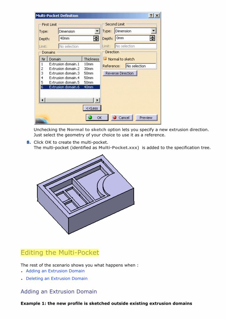
Unchecking the Normal to sketch option lets you specify a new extrusion direction. Just select the geometry of your choice to use it as a reference.
8. Click OK to create the multi-pocket. The multi-pocket (identified as Multi-Pocket.xxx) is added to the specification tree.
Editing the Multi-Pocket
The rest of the scenario shows you what happens when :● Adding an Extrusion Domain
● Deleting an Extrusion Domain
Adding an Extrusion Domain
Example 1: the new profile is sketched outside existing extrusion domains

9. Double-click Sketch.4 to edit it: for example, sketch a closed profile outside Extrusion domain.1.
10. Quit the Sketcher. A warning message informs you that the application has detected that the initial geometry has been modified. Click Close to close the window.
11. Double-click MultiPocket.1. The Feature Definition Error window displays, providing the details of the modification.
12. Click OK to close the window. The Multi-Pocket Definition dialog box reappears. The new extrusion domain Extrusion domain.7 is indicated.
13. Select it and define the value of your choice.
14. Click OK to confirm. Multi-pocket.1 is now composed of seven pockets.

Example 2: the new profile is sketched inside an existing extrusion domain
15. Double-click Sketch.4 to edit it: for example, add a closed profile inside Extrusion domain.2.
16. Quit the Sketcher. A warning message informs you that the application has detected that the initial geometry has been modified. Close the window.
17. Double-click MultiPocket.1. The Feature Definition Error window displays, providing the details of the modification:
When sketching a profile inside an existing extrusion domain, the application deletes that existing domain and replaces it with a new one. This is why the message window displays:
�❍ 1 extrusion domain deleted (Extrusion domain.2)
�❍ 2 extrusion domains created (Extrusion domain.8 and Extrusion domain.9, that replaces Extrusion domain.2)
18. Click OK to close the window. The Multi-Pocket Definition dialog box reappears. Extrusion domain.2 is no more displayed. On the contrary, two new extrusion domains Extrusion domain.8m Extrusion domain.9 are indicated with 0mm as their default thickness.

19. Select Extrusion domain.8 and define 40mm as the length value.
20. Select Extrusion domain.9, that is the rectangle, and define 30mm as the length value.
21. Click OK to confirm. Multi-pocket.1 is now composed of eight pockets.
Deleting an Extrusion Domain
21. Double-click Sketch.4 and delete
Extrusion Domain.5.
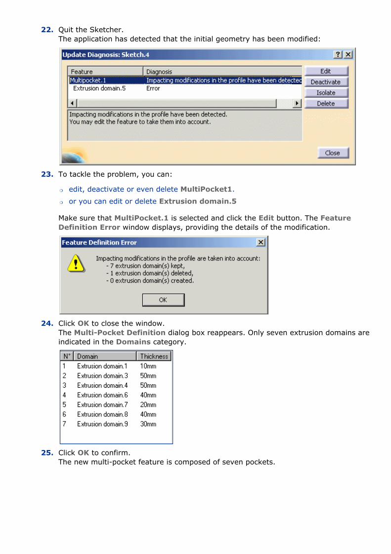
22. Quit the Sketcher. The application has detected that the initial geometry has been modified:
23. To tackle the problem, you can:
�❍ edit, deactivate or even delete MultiPocket1.
�❍ or you can edit or delete Extrusion domain.5
Make sure that MultiPocket.1 is selected and click the Edit button. The Feature Definition Error window displays, providing the details of the modification.
24. Click OK to close the window. The Multi-Pocket Definition dialog box reappears. Only seven extrusion domains are indicated in the Domains category.
25. Click OK to confirm. The new multi-pocket feature is composed of seven pockets.
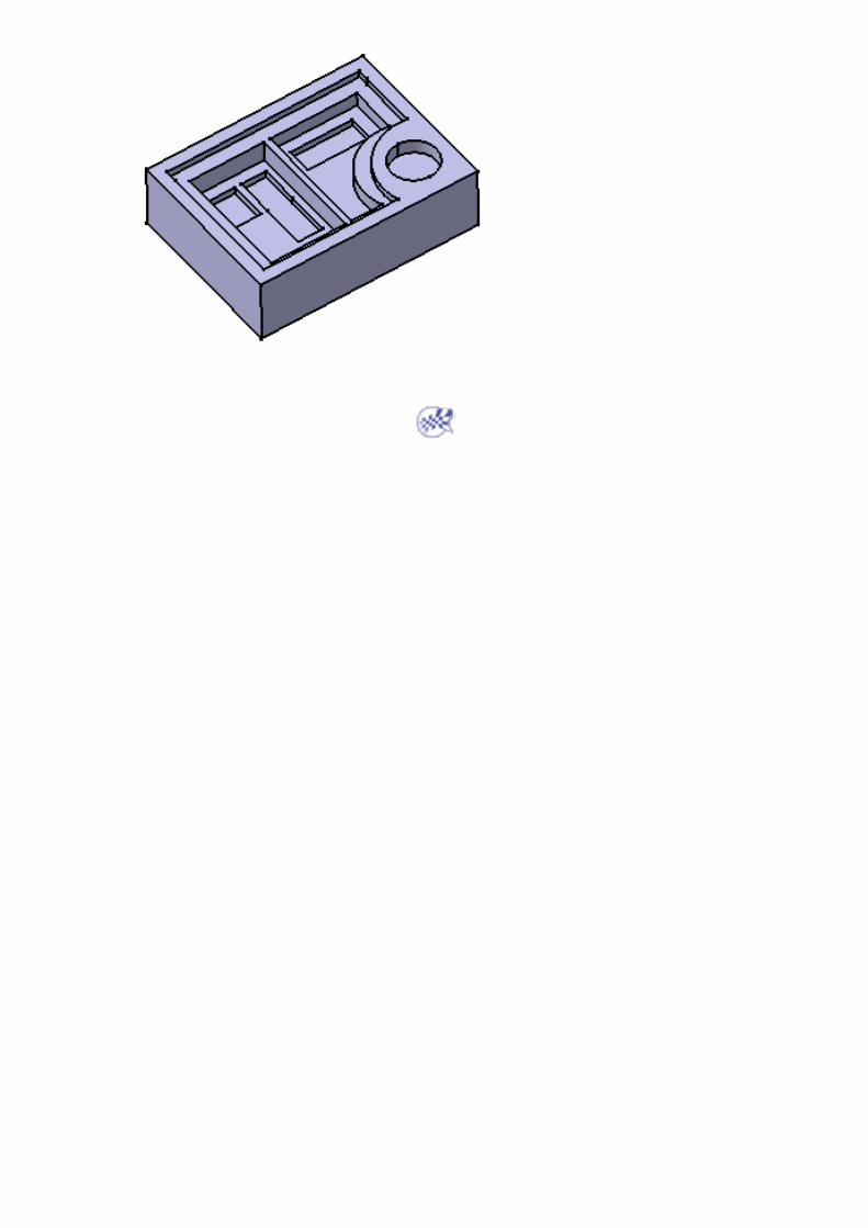

Creating Drafted Filleted Pockets This task shows you how to create a pocket while drafting its faces and filleting its edges.
We recommend you the use of this command to speed up your design.
Open the Pocket1.CATPart document.
1. Select the profile to be extruded, that is Sketch.2.
2. Click Drafted Filleted Pocket . The Drafted Filleted Pocket Definition dialog box appears and the application previews the pocket to be created.

3. Enter 22 as the pocket depth value.
4. Selecting a second limit is mandatory. Select Pad1 top face as the second limit. Your specifications for creating the pocket are now defined.
5. Let's go on with the draft definition. Enter 7 as the draft angle value. Drafting faces is optional. If you do not wish to use this capability, just uncheck the Angle option.
6. Check the Second limit option to define the neutral element. So, note that the pad top face is also used as the neutral element.
7. Enter 4 as the radius value to define the three fillets.
�❍ Lateral radius: defines the fillets on vertical edges
�❍ First limit radius: defines the round corner fillets
�❍ Second limit radius: defines the filets on the edges of the second limit.
Filleting edges is optional too. If you do not wish to use this capability, just uncheck the options.
8. Click Preview to check if the application can compute the fillets properly. Clicking Preview previews the pocket, the draft and the fillets and display them in the specification tree. If you have deactivated the draft or fillet options, the draft or the fillets are then displayed as deactivated features in the tree, i.e. with red parentheses. In the specification tree red parentheses appear on EdgeFillet.1, meaning that it cannot be computed by the application. Looking more closely at this fillet you can see that due to the shape of the initial sketch, it is effectively impossible to compute that fillet.
Note that there is a priority in the order of appearance of the fillets (from top to bottom) in the specification tree. The first fillet corresponds to the Lateral radius option in the dialog box, the second fillet to the First limit radius option and the last fillet to the Second limit radius option.
9. Click OK to create the features. If you look at the specification tree, you will note that you have created:
�❍ one pocket
�❍ one draft
�❍ two fillets
This implies that if you want to edit the drafted filleted pocket, you need to double-click the appropriate feature. This is your new part:
