part #d8089 large flat panel tilt mountdownloads.chiefmfg.com/manuals-i/mspdccpdpt-i.pdf · slide...
TRANSCRIPT

I N S T A L L A T I O N I N S T R U C T I O N S
PART #D8089Large Flat Panel Tilt MountThe Large Flat Panel Tilt Mount is a quick discon-nect mounting solution for large flat panel displays. The mount features adjustability between 0 and 15 degrees of tilt.
Once the tilt brackets are attached to your display, simply install the mount on a wall, lock the display in place, and attach your audio/video cables.
BEFORE YOU BEGIN
• Caution: To prevent damage to the mount, which could void factory warranty and affect the attached equipment, thoroughly study all instructions and illustrations before you begin the installation. Pay particular attention to the “Important Warnings and Precautions” on Page 3.
• If a defect is discovered after Dell’s initial 21-day Customer Satisfaction period, Chief Mfg. will, at its option, repair or replace the product at no charge provided it is returned during the warranty period. Please note contact information for Chief Mfg. listed below.
• Did you know that home consumers can purchase professional Plasma TV installation services through Dell? Through our third-party providers we offer home installation options ranging from simple unboxing and audio/visual component hookup to a Premier TV Installation with wall mount and professional installation of up to 5 home theater or surround-sound speakers. If you have purchased a Plasma TV Installation offer through Dell, a third-party installation provider should contact you to schedule your installation. If you need to schedule this service, please call 1-800-897-1582. If you would like to purchase installation services for your new Dell Plasma TV and have not already done so, please contact Dell sales at 1-800-915-3355. If you have purchased an installation package, but would like to upgrade your installation service, please call Dell Consumer Customer Care at 1-800-624-9897.
CHIEF MANUFACTURING INC.1-800-582-6480 952-894-6280 FAX 952-894-6918 8401 EAGLE CREEK PARKWAY EUROPESAVAGE, MINNESOTA 55378 USA [email protected]
8805-000086 (Rev. D)2004 Chief Manufacturing
www.chiefmfg.com02/05

Installation Instructions MSP-DCCPDPT
2
THIS PAGE INTENTIONALLY
LEFT BLANK

3
Installation Instructions MSP-DCCPDPT
IMPORTANT WARNINGS AND PRECAUTIONS!
WARNING: A WARNING alerts you to the possibility of serious injury or death if you do not follow the instructions.
CAUTION: A CAUTION alerts you to the possibility of damage or destruction of equipment if you do not follow the corre-sponding instructions.
• WARNING: Improper installation can result in serious personal injury! Make sure that the structural members can support a weight factor five times the total weight of the equipment. If not, reinforce the structure before installing the mount.
• CAUTION: Check the unit for shipping damage. See “PARTS LIST” on page 4.
TOOLS REQUIRED FOR INSTALLATION
• Socket Set (1/2” Socket)
• Phillips screwdriver, No. 2
NOTE: Other tools may be required depending on the method of installation.
CONTENTS
IMPORTANT WARNINGS AND CAUTIONS! .................. 2
TOOLS REQUIRED FOR INSTALLATION ....................... 2
PARTS LIST .................................................................... 4
INSPECT THE UNIT BEFORE INSTALLING.................... 5
INSTALL INTERFACE BRACKETS ON DISPLAY ............ 5
INSTALL WALL PLATE..................................................... 6
Lag Bolt Installation Instructions (Option A) ................. 6
Steel Stud / Dry Wall Installation Instructions (Option B).................................................. 7
INSTALL DISPLAY............................................................ 8
DISPLAY REMOVAL INSTRUCTIONS............................. 9
Installation Instructions MSP-DCCPDPT
4
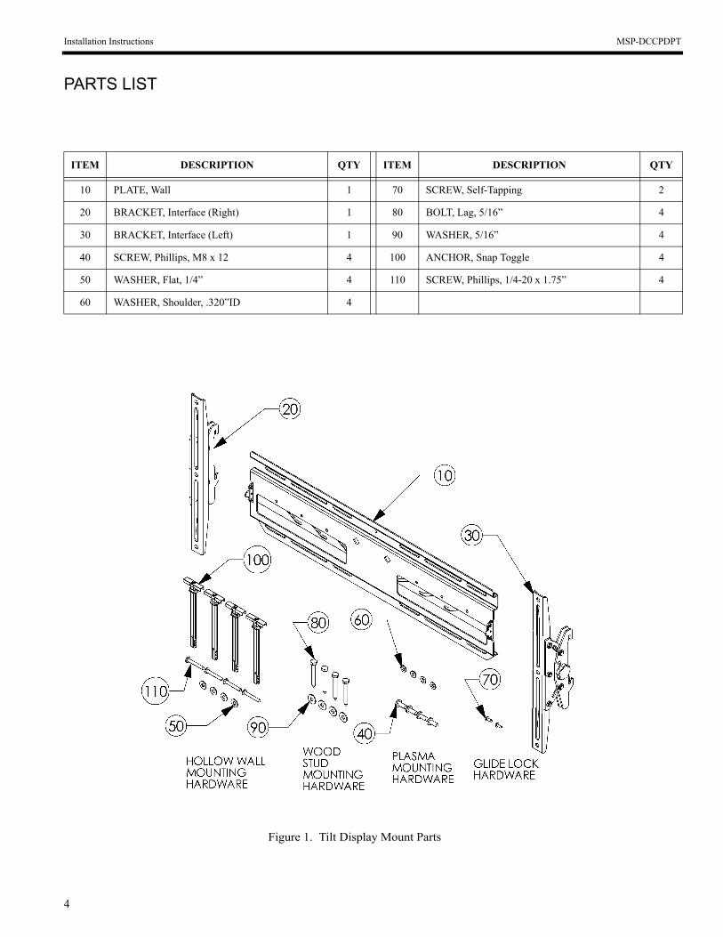
PARTS LIST
ITEM DESCRIPTION QTY ITEM DESCRIPTION QTY
10 PLATE, Wall 1 70 SCREW, Self-Tapping 2
20 BRACKET, Interface (Right) 1 80 BOLT, Lag, 5/16” 4
30 BRACKET, Interface (Left) 1 90 WASHER, 5/16” 4
40 SCREW, Phillips, M8 x 12 4 100 ANCHOR, Snap Toggle 4
50 WASHER, Flat, 1/4” 4 110 SCREW, Phillips, 1/4-20 x 1.75” 4
60 WASHER, Shoulder, .320”ID 4
Figure 1. Tilt Display Mount Parts

5
Installation Instructions MSP-DCCPDPT
INSPECT THE UNIT BEFORE INSTALLING
1. Carefully inspect the mount for shipping damage (see Fig-ure 1). If any damage is apparent, call your carrier claims agent and do not continue with the installation until the carrier has reviewed the damage.
NOTE: Read all instructions before starting installation.
2. Lay out components to ensure you have all the required parts before proceeding. See “PARTS LIST” on page 4.
INSTALL INTERFACE BRACKETS ON DISPLAY
Install the interface brackets as follows:
1. Place the interface brackets (20 and 30) on the back of the display, aligning the holes with the mounting inserts. See Figure 1 and Figure 2.
2. Secure the left and right interface bracket assemblies (20 and 30) to the display using shoulder washers (60) and screws (40). See Figure 3.
Figure 2. Install Brackets on Display
Figure 3. Attachment Parts

Installation Instructions MSP-DCCPDPT
6
INSTALL WALL PLATE
Select one of the following options to Install the wall plate:
• Lag Bolt Installation Instructions (Option A)• Steel Stud / Dry Wall Installation Instructions (Option B)
Lag Bolt Installation Instructions (Option A)
Install the wall plate as follows:
WARNING: It is the responsibility of the installer to verify that the structure to which the mount is anchored will safely support five times the combined load of all attached components and equipment.
1. Determine a suitable mounting location and lift the wall plate (10) into place (refer to “PARTS LIST” on page 4 and Figure 4.
2. Using a small nail or screw (not provided) in the center hole, lightly support the wall plate at the mounting loca-tion.
3. Level the wall plate (10) and drill pilot holes for anchoring the wall plate. If drilling into wood studs, use a 15/64” drill bit.
4. Using four 5/16” lag bolts (80) and 5/16” washers (90), install the wall plate on the wall.
5. Slide the latches to the outside.
Figure 4. Lag Bolt Installation

7
Installation Instructions MSP-DCCPDPT
Steel Stud / Dry Wall Installation Instructions (Option B)
Install the wall plate as follows:
WARNING: It is the responsibility of the installer to verify that the structure to which the mount is anchored will safely support five times the combined load of all attached components and equipment.
1. Determine a suitable mounting location and lift the wallplate (10) into place (refer to “PARTS LIST” on page 4).
2. Drill a 1/2” hole at the desired location, making sure wall is at least 1/2” thick. If the wall is made with metal studs, it is recommended to install the anchor through the dry-wall and the metal stud (see Figure 5).
3. With plastic anchor (100) inserted in hole, slide finger grip together to turn end inside hole perpendicular to wall(see Figure 6).
4. Slide plastic ring of anchor to the surface of the wall(see Figure 7).
5. Split finger grip ends apart to break of plastic ends flush with plastic ring of anchor (see Figure 8).
6. Using the outermost mounting holes of the mount as a template, repeat steps 1 through 5 for the remaining anchors.
7. Using the 1/4-20 Phillips head screws (110 ) and flatwashers (50), secure the mount to the wall (see Figure 9).
BREAK OFF PLASTIC ENDS
Figure 8.
Figure 9.
Figure 7.
Figure 6.
Figure 5.

Installation Instructions MSP-DCCPDPT
8
INSTALL DISPLAY
Install the display as follows:
1. Place the display on the wall plate (10) by hooking the hooks of the brackets (20 and 30) in the top of the wall plate (see Figure 10).
2. Secure the display by sliding the latches, one on each side, inward (see Figure 10).
3. If desired, install self tapping screws (70) and/or pad-locks (not provided) for additional security (see Fig-ure 10).
4. Tilt the display up or down as desired.
5. Tighten knobs to achieve the desired tension.
Figure 10. Install Display
9
Installation Instructions MSP-DCCPDPT
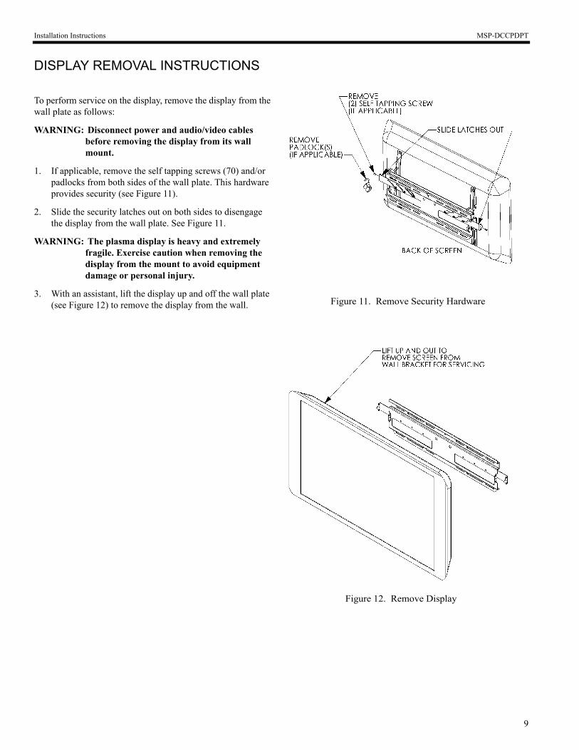
DISPLAY REMOVAL INSTRUCTIONS
To perform service on the display, remove the display from the wall plate as follows:
WARNING: Disconnect power and audio/video cables before removing the display from its wall mount.
1. If applicable, remove the self tapping screws (70) and/or padlocks from both sides of the wall plate. This hardware provides security (see Figure 11).
2. Slide the security latches out on both sides to disengage the display from the wall plate. See Figure 11.
WARNING: The plasma display is heavy and extremely fragile. Exercise caution when removing the display from the mount to avoid equipment damage or personal injury.
3. With an assistant, lift the display up and off the wall plate (see Figure 12) to remove the display from the wall.
Figure 12. Remove Display
Figure 11. Remove Security Hardware


PIEZA #D8089Soporte inclinable para pantallas planas grandes
INSTRUCCIONES DE INSTALACIÓN
El soporte inclinable para pantallas planas grandes es una solución de soporte de desconexión rápida para pantallas planas grandes. El soporte puede ajustarse de 0 a 15 grados de inclinación.
Una vez que los puntales inclinables están sujetos a la pantalla, simplemente instale el soporte en la pared, trabe la pantalla en su sitio y conecte los cables de audio o vídeo.
ANTES DE COMENZAR
• Precaución: Para evitar daños al soporte, los cuales pueden cancelar la garantía de fábrica y afectar el equipo sujeto, estudie detenidamente todas las instrucciones y las ilustraciones antes de comenzar la instalación. Preste atención especial a “Advertencias y Precauciones Importantes” en la página 3.
• Si se descubre un defecto después del período inicial de 30 días de Satisfacción al Cliente de Dell, Chief Mfg. reparará o reemplazará, a opción suya, el producto sin cargo siempre que se devuelva durante el período de garantía. Observe la información de contacto para Chief Mfg. más adelante.
CHIEF MANUFACTURING INC.1-800-582-6480 952-894-6280 FAX 952-894-6918 8401 EAGLE CREEK PARKWAY EUROPASAVAGE, MINNESOTA 55378 USA [email protected]
8805-000086 (Rev.B)2004 Chief Manufacturing
www.chiefmfg.com 10/04

Instrucciones de instalación MSP-DCCPDPT
2
ESTA PÁGINA DE DEJÓ EN BLANCO
A PROPÓSITO
3
Instrucciones de instalación MSP-DCCPDPT
¡ADVERTENCIAS Y PRECAUCIONES IMPORTANTES!
ADVERTENCIA: Una ADVERTENCIA le avisa la posibilidad de una lesión grave o la muerte si no sigue las instrucciones.
PRECAUCIÓN: Una PRECAUCIÓN le avisa la posibilidad de que haya daños o destrucción del equipo si no sigue las instrucciones correspondientes.
• ADVERTENCIA: ¡La instalación incorrecta puede causar lesiones personales graves! Asegúrese de que la estructura puede cargar el factor de peso redundante de cinco veces el peso total del equipo. Si no es así, refuerce la estructura antes de instalar el soporte.
• PRECAUCIÓN: Verifique la unidad para detectar si sufrió daños en el embarque. Vea "LISTA DE PIEZAS" en la página 4.
HERRAMIENTAS NECESARIAS PARA LA INSTALACIÓN
• Juego de casquillos (casquillo de 1/2”)
• Destornillador Phillips, núm. 2
NOTA: Podrían necesitarse otras herramientas dependiendo delmétodo de instalación.
CONTENIDO
¡ADVERTENCIAS Y PRECAUCIONES IMPORTANTES! .............................. 2
HERRAMIENTAS NECESARIAS PARA LA INSTALACIÓN............................. 2
LISTA DE PIEZAS .......................................................................................... 4
INSPECCIONE LA UNIDAD ANTES DE LA INSTALACIÓN ............................ 5
INSTALACIÓN DE LOS PUNTALES DE INTERFAZ EN LA PANTALLA ......... 5
INSTALACIÓN DE LA PLACA DE PARED ....................................................... 6
Instrucciones de instalación del tornillo de rosca (Opción A)....................... 6
Instalación en columna de acero/ pared de yesoInstrucciones (Opción B) .............................................................................. 7
INSTALACIÓN DE LA PANTALLA.................................................................... 8
INSTRUCCIONES PARA LA REMOCIÓN DE LA PANTALLA ......................... 9

Instrucciones de instalación MSP-DCCPDPT
4
LISTA DE PIEZAS
ARTÍ-CULO DESCRIPCIÓN CANTI-
DADARTÍ-CULO DESCRIPCIÓN CANTI-
DAD
10 PLACA, pared 1 70 TORNILLO, autorroscante 2
20 PUNTAL, interfaz (derecho) 1 80 TORNILLO, de rosca, 5/16” 4
30 PUNTAL, interfaz (izquierdo) 1 90 ARANDELA, 5/16” 4
40 TORNILLO, Phillips, M8 x 12 4 100 ANCLA, fiador oscilante a presión 4
50 ARANDELA, plana, 1/4” 4 110 TORNILLO, Phillips, 1/4-20 x 1.75” 4
60 ARANDELA, sostén, .320”ID 4
Figura 1. Piezas del soporte inclinable para pantalla

5
Instrucciones de instalación MSP-DCCPDPT
INSPECCIONE LA UNIDAD ANTES DE LA INSTALACIÓN
1. Inspeccione cuidadosamente el soporte para detectar daños en el embarque (vea la Figura 1). Si existe algún daño, llame al agente de reclamaciones del transportista y no siga con la instalación hasta que el transportista haya revisado el daño.
NOTA: Lea todas las instrucciones antes de comenzar la instalación.
2. Coloque todos los componentes a la vista para asegurarse de que tiene todas las piezas necesarias antes de continuar. Vea "LISTA DE PIEZAS" en la página 4.
INSTALACIÓN DE LOS PUNTALES DE INTERFAZ EN LA PANTALLA
Instale los puntales de interfaz del modo siguiente:
1. Coloque los puntales de interfaz (20 y 30) en la parte posterior de la pantalla, alinee los orificios con las entradas de montaje. Vea la Figura 1 y Figura 2.
2. Asegure los ensambles de los puntales de interfaz izquierdo y derecho (20 y 30) a la pantalla usando las arandelas de sostén (60) y los tornillos (40).Vea la Figura 3.
Figura 2. Instale los puntales en la pantalla.
Figura 3. Piezas de sujeción
Instrucciones de instalación MSP-DCCPDPT
6
INSTALACIÓN DE LA PLACA DE PARED
Seleccione una de las siguientes opciones para instalar la placa de pared:
• Instrucciones de instalación del tornillo de rosca (Opción A)• Instrucciones de instalación en columna de acero/ pared de
yeso (Opción B)
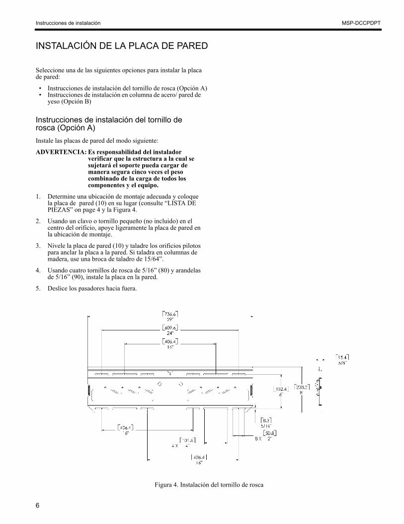
Instrucciones de instalación del tornillo de rosca (Opción A)Instale las placas de pared del modo siguiente:
ADVERTENCIA: Es responsabilidad del instalador verificar que la estructura a la cual se sujetará el soporte pueda cargar de manera segura cinco veces el peso combinado de la carga de todos los componentes y el equipo.
1. Determine una ubicación de montaje adecuada y coloque la placa de pared (10) en su lugar (consulte “LISTA DE PIEZAS” on page 4 y la Figura 4.
2. Usando un clavo o tornillo pequeño (no incluido) en el centro del orificio, apoye ligeramente la placa de pared en la ubicación de montaje.
3. Nivele la placa de pared (10) y taladre los orificios pilotos para anclar la placa a la pared. Si taladra en columnas de madera, use una broca de taladro de 15/64”.
4. Usando cuatro tornillos de rosca de 5/16” (80) y arandelas de 5/16” (90), instale la placa en la pared.
5. Deslice los pasadores hacia fuera.
Figura 4. Instalación del tornillo de rosca
7
Instrucciones de instalación MSP-DCCPDPT
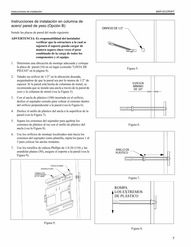
Instrucciones de instalación en columna de acero/ pared de yeso (Opción B)
Instale las placas de pared del modo siguiente:
ADVERTENCIA: Es responsabilidad del instalador verificar que la estructura a la cual se sujetará el soporte pueda cargar de manera segura cinco veces el peso combinado de la carga de todos los componentes y el equipo.
1. Determine una ubicación de montaje adecuada y coloque la placa de pared (10) en su lugar (consulte "LISTA DE PIEZAS" en la página 4).
2. Taladre un orificio de 1/2” en la ubicación deseada, asegurándose de que la pared sea por lo menos de 1/2” de espesor. Si la pared está hecha de columnas de metal, se recomienda que se instale una ancla a través de la pared de yeso y la columna de metal (vea la Figura 5).
3. Con el ancla de plástico (100) insertada en el orificio, deslice el sujetador cerrado para voltear el extremo dentro del orificio perpendicular a la pared (vea la Figura 6).
4. Deslice el anillo de plástico del ancla a la superficie de la pared (vea la Figura 7).
5. Separe los extremos del sujetador para quebrar los extremos de plástico al ras con el anillo de plástico del ancla (vea la Figura 8).
6. Use los orificios de montaje localizados más hacia los extremos del sujetador como plantilla, repita los pasos 1 al 5 para colocar las anclas restantes.
7. Use los tornillos de cabeza Phillips de 1/4-20 (110) y lasarandelas planas (50), asegure el soporte a la pared (vea la Figura 9).
ROMPALOS EXTREMOS DE PLÁSTICO
Figura 8.
Figura 9.
Figura 7.
Figura 6.
Figura 5.
Instrucciones de instalación MSP-DCCPDPT
8
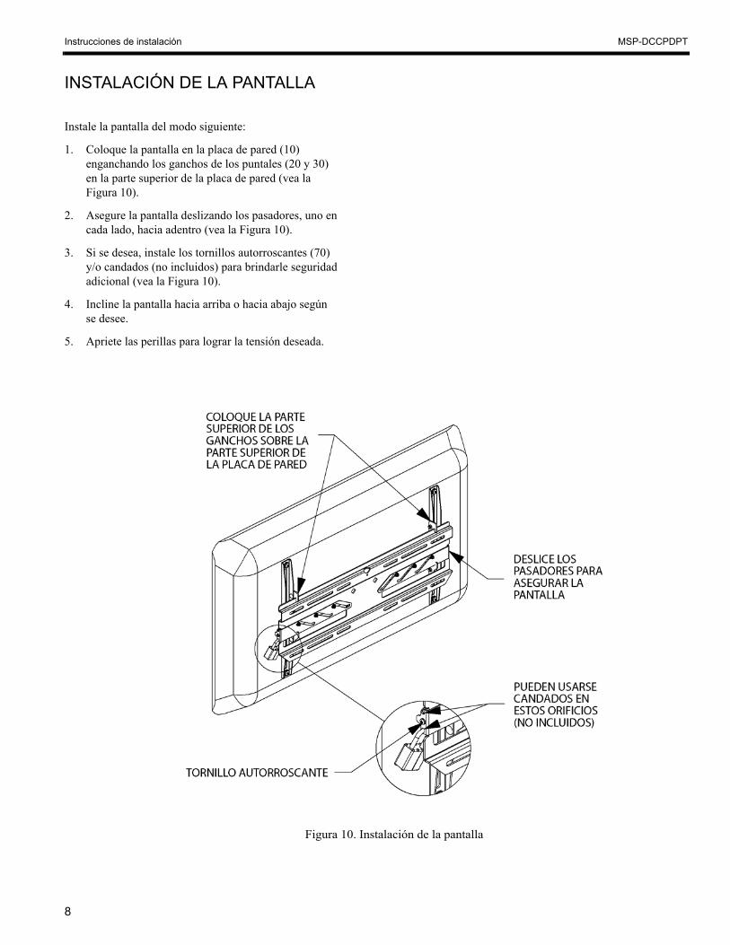
INSTALACIÓN DE LA PANTALLA
Instale la pantalla del modo siguiente:
1. Coloque la pantalla en la placa de pared (10) enganchando los ganchos de los puntales (20 y 30) en la parte superior de la placa de pared (vea la Figura 10).
2. Asegure la pantalla deslizando los pasadores, uno en cada lado, hacia adentro (vea la Figura 10).
3. Si se desea, instale los tornillos autorroscantes (70) y/o candados (no incluidos) para brindarle seguridad adicional (vea la Figura 10).
4. Incline la pantalla hacia arriba o hacia abajo según se desee.
5. Apriete las perillas para lograr la tensión deseada.
Figura 10. Instalación de la pantalla
9
Instrucciones de instalación MSP-DCCPDPT
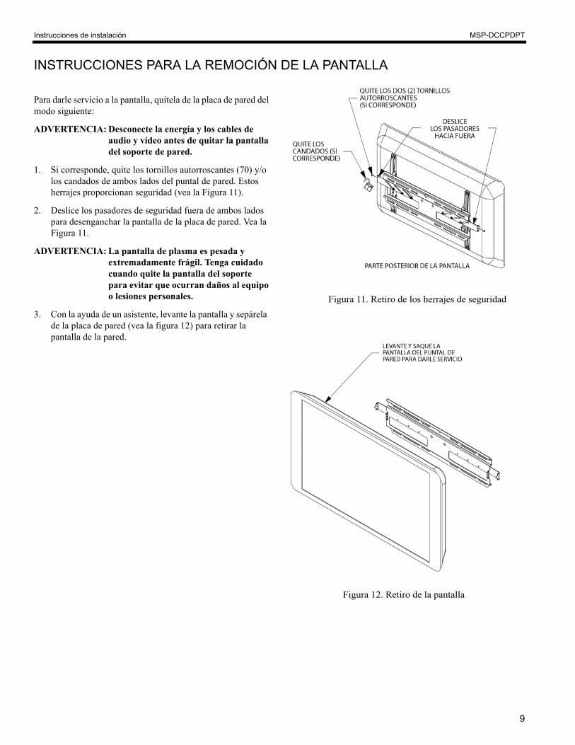
INSTRUCCIONES PARA LA REMOCIÓN DE LA PANTALLA
Para darle servicio a la pantalla, quítela de la placa de pared del modo siguiente:
ADVERTENCIA: Desconecte la energía y los cables de audio y vídeo antes de quitar la pantalla del soporte de pared.
1. Si corresponde, quite los tornillos autorroscantes (70) y/o los candados de ambos lados del puntal de pared. Estos herrajes proporcionan seguridad (vea la Figura 11).
2. Deslice los pasadores de seguridad fuera de ambos lados para desenganchar la pantalla de la placa de pared. Vea la Figura 11.
ADVERTENCIA: La pantalla de plasma es pesada y extremadamente frágil. Tenga cuidado cuando quite la pantalla del soporte para evitar que ocurran daños al equipo o lesiones personales.
3. Con la ayuda de un asistente, levante la pantalla y sepárela de la placa de pared (vea la figura 12) para retirar la pantalla de la pared.
Figura 12. Retiro de la pantalla
Figura 11. Retiro de los herrajes de seguridad

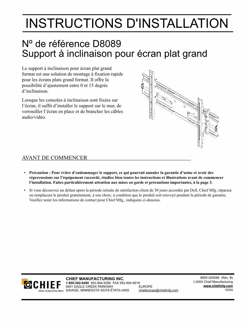
INSTRUCTIONS D'INSTALLATIONNº de référence D8089Support à inclinaison pour écran plat grand Le support à inclinaison pour écran plat grand format est une solution de montage à fixation rapide pour les écrans plats grand format. Il offre la possibilité d’ajustement entre 0 et 15 degrés d’inclinaison.
Lorsque les consoles à inclinaison sont fixées sur l’écran, il suffit d’installer le support sur le mur, de verrouiller l’écran en place et de brancher les câbles audio/vidéo.
AVANT DE COMMENCER
• Précaution : Pour éviter d’endommager le support, ce qui pourrait annuler la garantie d’usine et avoir des répercussions sur l’équipement raccordé, étudiez bien toutes les instructions et illustrations avant de commencer l’installation. Faites particulièrement attention aux mises en garde et précautions importantes, à la page 3.
• Si vous découvrez un défaut après la période initiale de satisfaction client de 30 jours accordée par Dell, Chief Mfg. réparera ou remplacera le produit gratuitement, à son choix, à condition que le produit soit renvoyé pendant la période de garantie. Veuillez noter les informations de contact pour Chief Mfg., indiquées ci-dessous.
CHIEF MANUFACTURING INC.1-800-582-6480 952-894-6280 FAX 952-894-6918 8401 EAGLE CREEK PARKWAY EUROPESAVAGE, MINNESOTA 55378 ÉTATS-UNIS [email protected]
8805-000086 (Rév. B)2004 Chief Manufacturing
www.chiefmfg.com10/04

Instructions d'installation MSP-DCCPDPT
2
CETTE PAGE EST LAISSÉE BLANCHE
INTENTIONNELLEMENT

3
Instructions d'installation MSP-DCCPDPT
MISES EN GARDE et PRÉCAUTIONS IMPORTANTES !
MISE EN GARDE : Une MISE EN GARDE vous avertit de la possibilité de blessures graves, voire mortelles, si vous ne respectez pas les instructions.
PRÉCAUTION : Une PRÉCAUTION vous avertit de la possibilité d’endommagement ou de destruction de l’équipement si vous ne respectez pas les instructions correspondantes.
• MISE EN GARDE : Une installation incorrecte risque d’entraîner des blessures graves ! Assurez-vous que les éléments porteurs peuvent supporter un facteur de poids redondant - cinq fois le poids total de l’équipement. S’ils ne peuvent pas supporter ce poids, renforcez la structure avant d’installer le support.
• PRÉCAUTION : Inspectez l’unité pour vérifier qu’elle n’a pas été endommagée en cours d’expédition. Voir « LISTE DES PIÈCES » à la page 4.
OUTILS REQUIS POUR L’INSTALLATION
• Jeu de douilles (douille de ½ pouce)
• Tournevis à pointe cruciforme, nº 2
REMARQUE : Vous aurez peut-être besoin d’autres outils, en fonction de la méthode d’installation utilisée.
TABLE DES MATIÈRES
MISES EN GARDE ET PRÉCAUTIONS IMPORTANTES ! .................. 2
OUTILS REQUIS POUR L’INSTALLATION ........................................... 2
LISTE DES PIÈCES .............................................................................. 4
INSPECTION DE L’UNITÉ AVANT L’INSTALLATION ........................... 5
INSTALLATION DES CONSOLES D’INTERFACE SUR L’ÉCRAN ........ 5
INSTALLATION DE LA PLAQUE MURALE ........................................... 6
Instructions d’installation avec tire-fond (option A)............................. 6
Instructions d’installation sur charpente d'acier / placoplâtre (option B) ......................................................................... 7
INSTALLATION DE L’ÉCRAN................................................................. 8
INSTRUCTIONS DE RETRAIT DE L’ÉCRAN......................................... 9

Instructions d'installation MSP-DCCPDPT
4
LISTE DES PIÈCES
ARTICLE DESCRIPTION QTÉ ARTICLE DESCRIPTION QTÉ
10 PLAQUE, murale 1 70 VIS, autotaraudeuse 2
20 CONSOLE, interface (droite) 1 80 TIRE-FOND, 5/16 pouce 4
30 CONSOLE, interface (gauche) 1 90 RONDELLE, 5/16 pouce 4
40 VIS, cruciforme, M8 x 12 4 100 ATTACHE, à levier encliquetable 4
50 RONDELLE, plate, ¼ pouce 4 110 VIS, cruciforme, 1/4-20 x 1,75 pouce 4
60 RONDELLE, à rebord, D.I. de 0,320 pouce 4
Figure 1. Pièces pour le support d’écran à inclinaison

5
Instructions d'installation MSP-DCCPDPT
INSPECTION DE L’UNITÉ AVANT L’INSTALLATION
1. Inspectez avec soin le support pour vérifier qu’il n’a pas été endommagé en cours d’expédition (voir la figure 1). S’il semble endommagé, appelez le service des réclamations de votre transporteur et ne poursuivez pas l’installation avant que le transporteur n’ait inspecté les dommages.
REMARQUE : Lisez toutes les instructions avant de commencer l’installation.
2. Référencez tous les articles pour vous assurer que vous avez toutes les pièces requises avant de continuer. Voir « LISTE DES PIÈCES » à la page 4.
INSTALLATION DES CONSOLES D’INTERFACE SUR L’ÉCRAN
Installez les consoles d’interface de la manière suivante :
1. Placez les consoles d’interface (20 et 30) au dos de l’écran, en alignant les trous sur les pièces d’insertion de montage. Voir la figure 1 et la figure 2.
2. Fixez les consoles d’interface gauche et droite (20 et 30) sur l’écran à l’aide des rondelles à rebord (60) des vis (40). Voir la figure 3.
Figure 2. Installez les consoles sur l’écran
Figure 3. Pièces de fixation

Instructions d'installation MSP-DCCPDPT
6
INSTALLATION DE LA PLAQUE MURALE Sélectionnez l’une des options suivantes pour installer la plaque murale :
• Instructions d’installation avec tire-fond (option A)• Instructions d’installation sur charpente d’acier /
placoplâtre (option B)
Instructions d’installation avec tire-fond (option A)
Installez la plaque murale de la manière suivante :
MISE EN GARDE : Il incombe à l’installateur de vérifier que la structure sur laquelle sera fixé le support est capable de supporter cinq fois la charge cumulée de tous les composants et équipements fixés.
1. Repérez l’emplacement de montage qui convient et soulevez la plaque murale (10) pour la mettre en place (voir la section « LISTE DES PIÈCES » à la page 4 et à la figure 4).
2. Placez un petit clou ou une petite vis (non fourni) dans le trou central pour soutenir légèrement la plaque murale à l’emplacement de montage.
3. Ajustez la plaque murale (10) à l’horizontale et percez des trous pilotes pour la fixer. Si vous percez dans une charpente de bois, utilisez un foret de 15/64 pouce.
4. À l’aide de quatre tire-fond de 5/16 pouce (80) et de quatre rondelles de 5/16 pouce (90), installez la plaque murale sur le mur.
5. Faites glisser les mécanismes de verrouillage vers l’extérieur.
Figure 4. Installation avec tire-fond

7
Instructions d'installation MSP-DCCPDPT
Instructions d’installation sur charpente d'acier / placoplâtre (option B)
Installez la plaque murale de la manière suivante :
MISE EN GARDE : Il incombe à l’installateur de vérifier que la structure sur laquelle sera fixé le support est capable de supporter cinq fois la charge cumulée de tous les composants et équipements fixés.
1. Repérez l’emplacement de montage qui convient et soulevez la plaque murale (10) pour la mettre en place (voir la section « LISTE DES PIÈCES » à la page 4).
2. Percez un trou de ½ pouce à l’emplacement désiré, après avoir vérifié que le mur a au moins ½ pouce d’épaisseur. Si le mur comprend une charpente métallique, il est recommandé d’installer l’attache dans le placoplâtre et la charpente métallique (voir la figure 5).
3. Lorsque l’attache (100) en plastique est insérée dans le trou, enfilez le taquet de préhension de manière à tourner l’extrémité se trouvant dans le trou perpendiculairement au mur (voir la figure 6).
4. Faites glisser la bague en plastique de l’attache jusqu’à la surface du mur ( voir la figure 7).
5. Séparez les extrémités en plastique du taquet de préhension de manière à les casser au niveau de la bague en plastique de l’attache (voir la figure 8).
6. En vous servant des trous de montage du support situés le plus à l’extérieur comme d’un gabarit, répétez les opérations 1 à 5 pour le reste des attaches.
7. À l’aide des vis cruciformes de 1/4-20 (110 ) et des rondelles plates (50), fixez le support au mur (voir la figure 9).
CASSEZ LES EXTRÉMITÉS EN PLASTIQUE
Figure 8.
Figure 9.
Figure 7.
Figure 6.
Figure 5.

Instructions d'installation MSP-DCCPDPT
8
INSTALLATION DE L’ÉCRAN
Installez l’écran de la manière suivante :
1. Placez l’écran sur la plaque murale (10) en accrochant les crochets des consoles (20 et 30) sur le haut de la plaque murale (voir la figure 10).
2. Fixez l’écran en faisant glisser vers l’intérieur les mécanismes de verrouillage, un de chaque côté (voir la figure 10).
3. Si désiré, installez les vis autotaraudeuses (70) et/ou les cadenas (non fournis) pour rendre le support encore plus solide (voir la figure 10).
4. Inclinez l’écran vers le haut ou le bas, comme désiré.
5. Serrez les boutons pour obtenir la tension désirée.
Figure 10. Installez l’écran

9
Instructions d'installation MSP-DCCPDPT
INSTRUCTIONS DE RETRAIT DE L’ÉCRAN
Pour effectuer la maintenance de l’écran, retirez-le de la plaque murale de la manière suivante :
MISE EN GARDE : Débranchez les câbles d’alimentation électrique et audio/vidéo avant de retirer l’écran de son support mural.
1. Le cas échéant, retirez les vis autotaraudeuses (70) et/ou les cadenas des deux côtés de la plaque murale. Ce matériel assure la sécurité de l’appareil (voir la figure 11).
2. Faites glisser vers l’extérieur les mécanismes de verrouillage des deux côtés pour dégager l’écran de la plaque murale. Voir la figure 11.
MISE EN GARDE : L’écran au plasma est lourd et extrêmement fragile. Faites attention lorsque vous retirez l’écran du support, afin de ne pas endommager l’équipement et de ne pas vous blesser.
3. En vous faisant aider par une autre personne, soulevez l’écran et retirez-le de la plaque murale (voir la figure 12).
Figure 12. Retirez l’écran
Figure 11. Retirez le matériel de sécurité