part comilation - defense technical information center · thf follodwing compwg"n part...
TRANSCRIPT

CUV~(NT PART NC2JICE
]HIS PAPER IS A G(qMfl"T PART OF THE FOLLOWIIN CUMILATIOW RPoPT:.
(IIhf) * n..s f te nt',rn ti onJ _qoferctv:e_on the Pleit rnlall of
al - K ic irne s~~h (81 olinic I liel i at (;ml
('~OU~t.E): __ iia .t i ni~i go, i e~ty for Terrai i-Vih le sy~t em,71__
To ORDER THE CoMPLETc CM1. ATI(.N REPoRT USE AD-149 b4-A
THE C(.(VtJ T PART IS PMDV1IED ERK M ALLOW USERS ACCESS TO INDIVIrJALLYAIJT140RED SECTIONS OF PROE.EDIMeS, AwA~L.s, SYMOSIA, ETC- HOWEVER ThECOPMNLNT sHOULD sE wNSMaM) WITHIN ZHE COWIEX7 M~ 7NE OVERALL tCWILAIIGNREPORT AND NOT AS A STANDALONE TECHNICAL REPCIRT-
THF FOLLODWING COMPWg"N PART NumtqDJs COWRISE THE COMILATION REPORT:
A I' "(0 . ' molo i sati i .1 . ' ' ho r Rourt eS t. iii Sol enC Viie
de I AmlTli ''tion -cf la rrs tion' (MOIlo ling of Off-IloaliTyres an i Soil 1:o hnprove I Tra t ion)
A.)- P) De )velopmnLn 0i it-Wh:cc m ttr;-ti )nl Mole 1
At)-1P004 2C') Soil IComqp I anin in'le e oti Ty re P r iarmisi-
A.1- 1W))', 26 I The Rollii e~i n v dO Si nkayie of Tow'' Dtial Wheel(xaT{'n 't Ion% in S: ii
A2-O)~262 Performan :-Pro ii ion of Pe~unaL i TyrV5 onI S,1n
AJ)-POOw 263 Effe-.ts of Slip on lFmergy Distribution between TPyre an,
A.)-Poo4 264 Tractton 0'orcel of ?i fvc Tyre on the Cokp.i:tei1 Soil
k)-)4 261) Pi,,-iuctP'r of In-S li Tire anti Wheee VehV- D Irawbar
,\0.P'O4 '266 flynanmI Simuiar Ion .,f Tral :k Layi ng Vchtt) is
A) 1)04 267 IDei lgz!I (O1f-o1 VchlcUns I wI rh Gool! Rid 600$ehv I 6or
AD-P0O4 Th68 VTreticht L~tmtvvi hur'p' giner Akct v-?P1eruvieg fk--tRa'>~chippor(A -r enrec It0 !nves-,fe. t ion of av Ac.-Ive
or~~y I~fr ~ hee '3 T'~torsi
frb&'e1~,jg ~ j Copy availlable to DTTC doecI ncr*

cOM)*T PAiR7 NOTICE CNT
AD-~ 'h( Le) ie Vol'ung4 PI gf rung uni Verbe.,%s erung des rAhrkomf g-rt sBetI SelIbstf 5von len Haumt'i. n en ' D'irch Rwitizv ogEl nsatbedinvit -, Ni c-k- und Hths -hwi n&F; -,Ken t. lnci. re l.
In Per,.'MI'- anl Tmvf.i t Rle Co.0 if"yt otSelf- PropelI le i Const ruct. on Ma( fine ry by R-'1u -f np, Pf t
anj Avert i a 'i r attIonl)
SAD-1004 27'0 St. rcsvs in S tu (pnrr~~t cq by 5ixllwv,
A.D 04 2 1 1 Fin.it e Elemen t Anal y si, Of Vr' mln iDeftO rMAOT. 6(cn11kit
AD- V 0.$. '71 A Rig for 4TeI t ri the .3ft So I Pe rtot)rmnn., o f Tr V< k
Ad - P,~ I D' Di Abh~iee I gk -it de r ao-lent ri fae iyk, !f v uriItzZugkrA ft von ler Al et. an.l 'oiiO kr en pl 1' ell(The Dep~oren.:- o ;oil Bi~tting 'nat It ar' Dra WbarPull oil z_11' iS aBdY ig het wecn 1'rack Plates)
All,' 1004 274 The Dynai I itcera t. ol' herween Tra k Ain. Soit
AD )1'.1 Analy~1 s of C P~tn ressi~~kre Dt st.rIbutLon Bre0Trackt-i Mo-le) wizzh Rppe-.t to Exte,.nal' Loz,.in .
A- O427 , A (7oip~ rison bet. woo,, L. Convent ional Metfho anirIrmprovel M etho Il for Prell t ~ng Tracked Vehi.:. e 1' formall f:
AD-1P0014 777 F,"fect of Hit 'h Posi tins on~ rx Performa, of T-a-k/GrouserSyestemis
AD-iq)04 '2761 Grousecr Effo-rt. Stiles
*D_ FI 14 27?9 R~de (Cofort of Off-Road Vetitcles
AiY-P(Th4 280 Fujrtheqr Development ira Rifle Quality Assessmaent
~D~{0.281 Gowp~rIort of NMoisured wad Situate-1 R!Ie Cortorr for anAgrtcultural Trm- tor aT4 Tnfluknce of Travel Spe. l an-ITyre-trfl-at 1('r Presmure o( Dynaic Rm
AD-pf 004 282 CIxracterist, s~ of Frazi 'Kied Proffles aq Sources ofTractor Vibr.,tfo
riat 1I oil/o
.1nt
1 li-

N 361
-NJA COMPARISO)N BETW 'N A CONVENTIONAL. M(THOD AND) AN IMPROVED
METHOD FOR PREO CAING 'TRACKED VEHICLE PEREFORMANCF
Da J.Y. WONG and .,K PRESTON 'THOMAS, TRANSPORT TECHNOLOGYNI RESEARCH LABORATORY, CARLETON UNIVERSITY, OTTAWA, CANADA
.- a- IN CRODUCTioN
0One of the most woidely used conventional mrthod& for ,*rcdictinq trackedSvehicle performan-ce is based on the assumption ttvit the track in contact
with the terrain is equivalent to a rigid footioig. Furthermore, a uniformn rormal pressure distribution (ver the entire contact area is as-sumed if
06 the centre of rgravity of tho! veliicle s located at the rni'poitit of thecontact lWngth. On Che odher tand, if the centre of gJrav- 'ty is locatednin front or behind the idcpoint of the contact length or if load transfer
0 due to dra~bar pull tak-2s place a sinkage distribution of trapezoidalSsh~ipe will Owcn bt a~surned. Based on these atsumptions and the
mea:ured pressuret sink"g and slwar stress d&%placement relationships,)f the terrain, tlhe tractlvo performance, of tracked vehklei. is predicted.
Experimentai ev'idence ha7. shown tl,t while the conventional method mayfind appications in the #:rediction of the performance of crawlers withlow ratio% of roadwheel spacing to track pitch, coatrwonly used in agriculttrm.- an~l the cortstiuction industry, it gives unrealistic 1p.r4diction ofthe performar"ce of tracked vehicl#os with high ratios of roactwheel spacingto track~ pitch designed for high speed operations. In the latter case,the normal Dresture is usually concentrated under theW roadwheels and isfor from uniform. Consequently, the track in contact voith the deformable terrain deflects and has the larm of a curve. Furthermore, ane~lement ot the terrain under the track is subjeczt to repetitive ciormal andshear loadings of the consecutive roadwheels. To take the;e factors intoaccount, an improved method for predicting the performance af tracko'dvehicles with relatively short track pitch hLs been dle.eloped. Theobjective is to proviide 'he designer, the procuremcrnt manager and thetest engineer with a qo.anti tative means whereby the cffects of vehicledesign parameters arid terrain conditions on performance can be assessedmore realistically than using the conventional method.
This ptper cescribes a -o+arirwn of the normal pressure disitibutior.,sin""g and dvawbar pull slip re!%tionship of a tracked vehicle itpredicted using the conventknal and the Improved tmethoda,
If'--CO'VEN TI WAL MTUH)I
0One of the widiely used #conventional methods assume% tha*t thet track;4behaves 9*,ke a rigid footing. With the centre oi gravity of the vehicleat thve midwiont of the contact inrgth. the, normal pr-essure distributionis assumed to be uniformly distributed as show, In Fiq, 1. On the otherIh"nd, if ihe centre of gravity is located in front or 1hehir~d the midpointof the contact, lerlyth, a sinkage *lisribolkw- of trirot a i~aesasuiumed.

If the pressure- sinkage trelationship of the terrain is known, such ins thatshown In Fig. , then the snkcge z of the track can he predicted byequating M3 rectioe due to normal pressure p with the vehicle weightIJ (21. The functional relationstp between sinkagrs z an6 pressurt p
for a given terrain can generally La expressed by
z-f (P)
z c"litO, bn mentioned that the pruaiure-slnkag* relationship rmy varywith *rrakz and ronditions. Vml&.,j& tU;,z " en pr-posedfor characterling the pressure-sinkage relatilons of different kinds oftarrain as described in references (I), (2), (3), (4) and (S).
Basfel on the predicted track sinkage z9, the motion resistance R duo toterrain compaction can be predkc1 ed as foliowt
R = b fz' pdz (2)0
w;.re b Is the width of the track.
In addition tW resistance due to compaction, the trawk my encounterresistame d to bu4idozing effects (QI. This should be taken into accountin determining the total motion resistance.
If the shear stress - displacement relationship of the terrain under, anappropriate normal pressure p Is known, such as that shown in Fig.1,the tractive effort of a track F can be predicted as follows:
F = b / dx (3)
where t li the length of the track and s is the shear stress under thetrack which varies along ti- contact length (I), (2).
if the shear stress - displacement relationship can be described by asimple exponential funrction (1)(2), the tractive effort F at a given slip Ican te expressed by (1)(2)
F (Ac + Wtan#) I- K (1 -iL/K]
( )
whore A and W arm the contact area and normal loud of the trck,r-spetivoly, c and 4 are cohesion and tngle of internal shearing resit-arve of the tnrrhn, respectively; K Is the sheer deformation modulus ofthe terrai,.
It shouic tp. p~r d aut lhet the shear stress-diapliwAment relationshipmay vary with torok typ* atnd cnditions. Various mthods have beenprpopamw for charwctL*r1r kh, shear stress - displbcement relatkrnsof different kind% of terraLi .4 discussd in referencea (1)(2) and (6).
Based On the pradicted motion rasisrtnce and tractive effort, the drawbarpui -silp r ettoishlp of 'tracltd vehicle can then be estlmated. Thedrawber pull-slip relatonship f ars; a besis for the cospsriew. andevalutkn of the trectiv* performence of 4f-rd vehicles.

363
THE IMPROVED METHOD
When a tracked vehicle with relatively short track pitch travels over adeformable terrain, the normal load is usually concentrated under theroadwheels. However, the track segments between the roadwheels alsotake up load(7). As a result, they deflect and have the form of a curve.Furthermore, an element of the terrain under the track Is subject to therepetitive loading of consecutive roadwheels (8). To predict the normz.lpressure distribution on the track-terrain Interface, the pressure-sinkage relationship and the response to repetitive loading of the terrainhave to be measured. Fig. 2 shows the response of a muskeg to repetitiveloading (4). It shows that the stiffness of the muskeg during unloadingand reloading is much higher than that in its virgin state and that itexhibits a certain amount of hyster, sis.
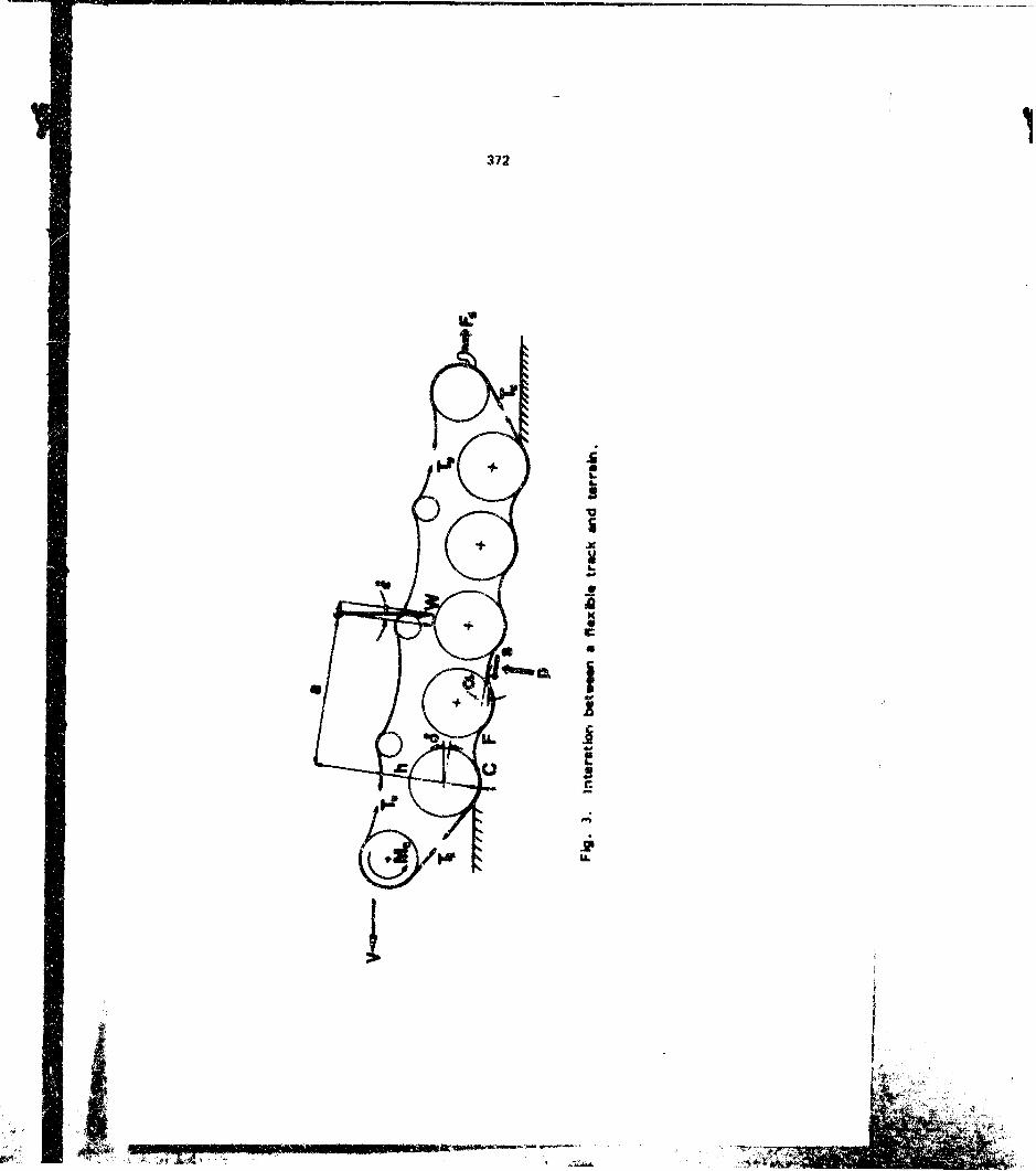
When the terrain characteristics are known, the prediction of the normalpressure distribution is reduced to the determin3tion of the swre of thed-flected track in contact with the terrain. A detailed analysis of tiemechanics of track-terrain interaction has been made. The track systemwith the major interacting forces are shown in Fig. 3. In the analysis,it is assumed that the track is equivalent to & flexible and inextensibiebeit and that te rmdwheels are rigidly connected to the vehicle body.A set ot equations for the equilibrium of the forces arid moments actingon the track system and the conservation of overall track length havebeen derived. They establish the relationship between the shape of thedeflected track in contact with the terrain and vehicle design parametersand terrain characteristics. The solution to this set of equations definesthe sinkages of the roadwheel, and the shape of the track segmentsbetween roadwheels. From these, the normal pressure distribution undera moving tracked vehicle can be predicted. The details of the analysis,ire described in reference (9).
To predict the shear stress distribution, the shear stress-displacementrelationship of the terrain and the characteristics of the track-terrainshearing have to be determined. It should be mentioned that an elementof the terrain under the track is also subject to shearing action of arepetitive nature. This is because the normal load applied to an elementof Ithe terrain under the track varies as the consecutive roadwheels rollover it. As a result, for a terrain exhibiting frictional behaviour, itundergoes the loading--unloadIng-reloading cycle In shear, simil " tothat for norral load. To predict the shear stress distribution ,-wn thetrack-terrain Interface, the response to repetitive shear loading of theterrain must be known,, Fig, 4 shows the response of a frictionalmedium (a dry sand) to repetitive shear loading. It Indicates thatfor a frictional terrain, the shear stress-displacement relationship duringreloading is similar to that with the terrain in its virgin statet. Thismeans that when re-shearing takes place after the previous loading-unloading cycle, the shear stress does iot Instantaneously roach itsmaximum value for a given normal stress. Rather a certain amount ofshea"r dispicement must take place before the maximum shear silress canb2 drveloped, simrilar to that when the frictional medium Is being shearedin its virgin state. This phenomenon has been taken into account In theanalysis. Together with the knowledge of the shear displacement developed under the track, which can be determined by a kinematic analysis ofthe track W sed on the concept of slip velocity (1) J 2), the shear stressdistribution under the track can then be predicted. Fig, 5 Illustrateshow the clevelopment of !he %her stress under the track y he modified4f the response of a frictional Zerrain to repetitive snear loading is takeninto a ccufnt for an idealized ase. It should be pointed out that when the
.. ... ....... .. .4"r s -- : "" : - , . ...... . . . .. ...; : :" 5"
: i - , :'

364
repetitive shearing characteristk-s ef the terraIn are taken Into consider-ation, the predicted total tractive siffort of the vehicle at a given slip "saybe considerably lower then that whon 'hey tr; not takcn into account,as can be seen from Fig. 5. The details of Ithe analyslis aire given Inrefet -me (9).
When the normal pressure and shear stress distributios hove been deter-mined, the motion resistance, tractive effort and drawiar pull as functionsof slip can be predicted. The prediction procedures have been programmedon a Hewlett-Pockard 98457 micrucomputer. The required Inputs Includeboth the vehicle and terrain parameters. The computer outputs includenormal pressure and sheer stress distributions, sinvkage.. motion resistance,tractive effort and drawbar Pull 3t a given slip (8) (11).
A-COMPARISON BETWEEN4 THE CONVENTIONALMT(O DAND THE IMPROVED METHb
The normal pressure distribution, the sinkage of the track and thA drawbarpull-slip relationship of a tracked vehicle, with basic parameters shown !nTable 1, operating over & variety of terrains were predicted using theconventional and the improved methods. The parameters used to character-ite the pressure- snkage relationships and the response to repetive normalIced for a sandy terrain and two muskegs are given In Tables 2 and 3,r,,spectively., The shear strength parameters of the terrains used in thepredictions are given in Table 4. For further Information concerning themethods used to characterize terrain behavlour, please refer toreferences (3), (4), (5), (6) and (9).
A comparison between the predicted normal preswure distributions usingthe convent lanai and the lmptove1 methods and field measurements over asandy terrain and a muskeg are shown In Figs. 6 and 7, respectively. Itcan be seen from Fig. 6 that over the sandy terrain the maximum preisurepredicted~ by the improved method is quite close to the measured one,whereas that estimated using the conventional method is 163.7 kPa, onlyabout 10% of the maximum measured pressure. Over the muskeg, thenormal pressurc6 estimated using the conventional nethod is again 43.7kPa,about 40% of the maximum measured. However, the maximum normalpressure predicted using the improved method Is aigain quit* close to themaximum measured as shown in Fig. 7. The reason Is that In the improvedmethod the response of the terrain to repetitive normal loed has beentaken into account. As mentioned previously, after the terrain has beencompacted by the first roedwheel, It becomes much "stiffer' than in itsvirgkii state. This promotes the concentration of normal pressure underthe roadwhools. The behaviour of tlhe terrain during the unload ing- ralow d-Ing cycle shown in Fig. 2 also explains why it Is possible that the normalpressure at a point on th, track segment between two adjacent roadwheelscan be as low as zero, white the sinkage at that point as measurod fromthe original terrain surface is not zero.
Figs. 0 and 9 show a comparison between the predicted sinkage& of thevehicle usingi the conventional eand the improved melhods and the measured.iinkages over the two type* of trrain. It can be seen that in genoelthe conventknal meathod un~derestimates the sikage. This Is because thenworml pressure estimated using the coniteniil method Is constierablylower than the actual maximum pressure. On the other hand, it can toLseen that fair to good agreemelnt Rxists betwiiiin the measured sinkages andthose predicted using thn I mproved mathu..
NNW

266
A comparison between the measured drawbar pull slip curves and thosepredicted using the conventional and the improve-i methods over thesandy terrain and the muskeg are sho-yn in Figs. 10 and il, respectively.It can be seen that the conver.1orial method overestimates the drawbarpull of the venicle over thew fuil range of vehicle slip, particularly atlow track rlips, It is also shown that the-re is a close agrement betweenthe meaisured drawbar pull arid that predictedl using the improved method.This is because the improued method gives a more realistic prediction ofvehicle s~nkage and hence motion resistance. Furthermore, the restp.onseof the terrain to repetitive &hear loading, as described in the previousSection, has been taken Into account in the Improved method.
It is interesting to note that the significant difference in the d~rawbarperform3nice between a crawler used in construction industry and a highspeed tracked vehicle of similar size and weight reported in reference (10)ix parallel to that between the two drawbar pull-slip curves shown inFigs. 1'0 arid 11.
CLOSING REMARKS
It is shown that the imnprov~ed method ou*.;4-ecl in this paper gives a morerealistic prediction of the performance o(' tracked vehicles with high ratiosof roadwheel spacing to track pitch than the conventional method. Theimprovement achieved is due primarily to the inclusion of the respoose ofterrain to repetitive normal and shear loadings and to the detailedanalysis of' the mechanics of track-terrain Intcraction.
It is 1'cevedl that the improved method outlined in the paper providesa quantitative means for eualuating the effects, of vehicle design para-meters and terrain conditions on tracked vehicle performance and forcomparing the performance of different tracked vehicle designs.
ACKNOWLEDGEMENTS
The improved method outlined in this paper was developed under contractarrangements with the Department of National Defence, Canada, throughthe Department of Supply and Services. The project was administered bythe Vehicle Mobility Section, Defence Research EstablIshment Suffield,Alberta, Canada.

36
REFERENCES
I. M.G. Dekker, Introduction to TerraI- --Vehicle Systems,The University of Michigan Press, 1969.
2. J.Y. Wang, Theory of Ground Vehicles, John Wiley, New York,1978. Russian *dition, Machlnostronle Publishers of Moscow,U.S.S.R., 1982.
3. J.Y. Wang, "Data processing methodology in the characterizationof the mechanical properties of terrain", Jour.-wal of Terramechlits,Vol. 17, No. I, pp. 13-4I, 1980.
4. J.Y. Wang, .R. Radfort%, and J. Prestor-Thomas,nSome furtherstudies on tha mechanical properties of muskeg in relation to vehiclemobility", Journal of Terramechanics, Vol. 19, No. 2, 1912.
5. J.Y. Wong and J, Preston-Thomas, *On the characterizationof the pressure-sinkage relationship of snow covers containingan Ice layer", Journal of Terramachanics, Vol. 20, No. I, 1983.
6. J°N. Wong and J. Preston-Thomas, "On the characterization ofthe shear stress-displacement relation;,hip of terrain',Journal of Terromechanlcs, Vol. 19, No. 4, 1982.
7. M.G, Bekker, Theory nf Land Locomotion, The University ofMichigan Press, l9S6.
8. J.Y. Wang. "An Inproved method for predicting tracked vehicleperformance", Proceedings of the Second Europan Conference ofthe International Society for Terrain-Vehkle Systests, Ferrara,Italy, October 3-5, 1983.
9. J.Y. Wang, M. Garber, and I. Preston-Thomas, "Theoreticalprediction and experimental substantiation of the ground pr-essuredistribution and tractive performance of tracked vehicles",to be published.
10. D.R. Freitag, Discussion on a paper entitled "Measurement of soilshear strength and deformation modull and a comparisen of theac ual and theoret"il performance of & family of rigid tracks".by B.M.D. Wills, Journal of Tertamechanks, Vol. 2, No. I,pp. 93- 5. 1965.

Vehicle Parameters
Vehicle Weight, kN 88.72
Number of roadwheels (for- one track) 5
Radius cof roacdwhejs, #n 0.31
Dlst3nce between roadwheeIs, iA 0.67
Distance between the centres oC' the sprocket andthe terisionq wheel, m '4.03
Width of track, rn 0.38
Tra',k pitch, mn 0.15
Initial track tension, kN 8.54
~"tI,,ht of the tr-awk per unit length. kN/m 12
Atgtof track grouserz, cmy 4. 7
%lumber Lf .upportlii rt~~f
Angle of approach of the tracK, cisgrees 23.8
Angle of departure of the track, degrees 16.'4
Lxxcatk-or. ot cei*.,-e %,' gravity in the longitudinaldirection (in front of the mid point of the trackcontact length), m 0.13
HiLight cf the centre of gravity, m 0.99
Location of drawbar In the longitudinal direction(distance from the mid puirit of the track contactlength), in 229
Height of drawbar, m 0.75

368
Table 2
Values of the Pressure -Sinksce end Repetitive Loading
Parameters for a Sandy Terrain (LETE Sand)
k ck0n k 0A
k N/mnI kNIm n42 kNim 3 kN/Im4
102 5301 0. 793 0 503, 000
Note: k 0and A U re parameters used to characterize the response
to repetitive normal loadig.
Tab~e 3
Values of the Pressure -Sink age and Reptitive Loading
Parameters for Two Tr~es of NMuskeq
Musk~eg Type Petawawa Muskeg A Petawawa Muskeg ~3
k kN~m 290 762m
M ,kN/M 3 51 97
A k N/ ni 4235402f70
Ncnte, k and A Uare part-meters used to chaT acter ic ti'e re~~ to
nor mi Iofidwl~g.

389
Table 4
Shear Strength Parameter~s of Various Types of Terrain
Terrain Type of Cohesion Angle of KT'Pe Sheariny (Adtwsion) Shearing
ResistancekP& degrees cmn
LETU 1.~na 27 31.1 1.1
LEIF ubesand, sand .6627. 5 1
retawawa Pt aIMuskeq ilnteni) 2. 4139.4 3.1A
mulkzq intervmI)

3/0
Pi
r-f(p)
f (pf
IAven te fol iv

31
eVprwiee*e ftw ai*jPa or - 1 d-
Tke f*e*fts r&44WO oP.The X.,.cr...ns Oci6)1
146Pr#**ure EXt
~so
0I-
S 66-
4:;
lie
v' 46 o/ " vb pf-0
Hg . Respnw~ of a musk..; k) reptjtj%,o normal 104d.
372
+
.CC
4,4,
LI. I

:~ 73
2 I-
4..
0~
1,~
t 0C
IN..,.
U
L
0
.~1.
0

I IN
/7
Ll v ' 'Py n Of tar stre s un c r a tr ck o efictkw)I trran predited by j t)* cnrventionalmet? A d ) the JniprovoC, ,-Iethod.
'T7

Q..
4-I
-orx3
Lo
C-0.
Lii nssjc(Qdl)~

376
0---
3
(LJ in4.)M sin s L

377
VI
0
S.0 1p
CL
LU L
v 44 +
+ 06
+ ++
(WO) 06jul

378
r)
a) o
) + +
W +W +
+
"_ + " I --+I ,n0) + '+ +
"+
L
i: + L .......
CS) m to
Pok

370
-"S
I 0U-) 13 u
w ~C*.L > £-a, a i
-.
++
Cfl In v ~ -MU-L
(WI I1 1d iv qmeu,,

380
Cp
U) 09L . > , l
CL c~
++
IIIt
v
cc+4 Alla
+
CDft
I d vva