part c - bangladesh power development...
TRANSCRIPT

PART C:
GUARANTEED TECHNICAL PARTICULARS
OF
33 KV, 2x5/6.67 MVA RURAL TYPE SUB-STATION MATERIALS

C.8.1: TECHNICAL PARTICULARS AND GUARANTEES OF 33/11KV, 5 /6.67 MVA POWER TRANSFORMER
(To be filled up by the Manufacturer in the Manufacturer Letterhead Pad with appropriate data otherwise the bid shall be rejected)
Sl. No. Description Unit BPDB's
Requirement
Manufacturer's guaranteed Particulars
1. RATING AND PERFORMANCE 1.1 Manufacturer’s name & country - To be mentioned 1.2 Manufacturer’s model no. - To be mentioned 1.3 Continuous maximum rating (ONAN/ONAF) MVA 5/6.67 MVA 1.4 No. of phases Nos. 3 1.5 Rated frequency Hz 50 1.6 Winding Insulation - Uniform 1.7 Normal transformation ratio at no load KV 33/11 1.8 Rated HT voltage (phase to phase) KV 33 1.9 Maximum HT voltage (phase to phase) KV 36
1.10 Rated LT voltage (phase to phase) KV 11 1.11 Maximum LT voltage (phase to phase) KV 12 1.12 Installation - Outdoor 1.13 Type of Transformer - Core, Conservator,
Oil immersed
1.14 Direction of normal power flow - HT-LT 1.15 No of windings Nos. 2 1.16 Bushing materials - Porcelain 1.17 Type of cooling - ONAN/ONAF 1.18 Coolant - Mineral Oil free from
PCB as per IEC-60296
1.19 Type of earthing - Effectively earth 1.20 Type of base - On wheels with
adequate size and length of rails and fixing arrangement
1.21 Phase connection: a) 33 KV winding with bushing CT b) 11KV winding with bushing CT
- -
Delta Star
1.22 Vector group - Dyn11 1.23 Neutral to be brought out :
a) HT b) LT
- -
Nil Yes
1.24 Basic Insulation Level (BIL) : a) High voltage winding b) low voltage winding
KV KV
170 75
1.25 Maximum winding temp. rise over 400C ambient (at CMR & normal tap change position) supported by Design Calculation sheet (to be enclosed) on the basis of Design Data
0C 65
1.26 Maximum top oil temp. rise over 400C ambient (at CMR & normal tap change position). supported by Design Calculation sheet (to be enclosed) on the basis of Design Data
0C 60

Seal & Signature of the Manufacturer
Seal & Signature of the Bidder
Sl. No. Description Unit BPDB's
Requirement
Manufacturer's guaranteed Particulars
1.27 TEST VOLTAGE :
Impulse front wave test voltage (1.2/50 micro sec. wave shape) : a) High voltage side b) low voltage side
KV KV
170(min) 75(min)
1.28 Power frequency withstand test voltage for 1 (one) minute: a) High voltage side b) low voltage side
KV KV
70 28
1.29 Short circuit MVA available: a) at 33 KV b) at 11KV
MVA MVA
1500 500
1.30 Impedance voltage at 75 0C and at normal ratio and rated frequency and at ONAN condition.
%
7 %
2. VOLTAGE CONTROL 2.1 a) Type of tap changer control
- The tap changer will
be Off-Load type, manually operated.
b) Name of manufacturer& country of origin To be mentioned
c) Type /model no To be mentioned
d) Current rating of contact A To be mentioned 2.2 Nos. of tapping 9 2.3 Tapping steps - +10% in steps of
2.5% 9 tapping i.e. 33+4x2.5%
2.4 HV or LV winding - To be mentioned 2.5 Power frequency withstand test voltage between first
and last contracts of the selector switch between diverter and switch contract.
KV 75
3. GENERAL
3.1 Manufacturer’s Name & Address To be mentioned
3.2 Material of core & grading To be mentioned
3.3 Core Loss/ Kg, supported by Characteristic Curve (to be submitted )
To be mentioned
3.4 Thickness of core, mm To be mentioned
3.5 Core Dia, mm To be mentioned
3.6 Total weight of core, Kg To be mentioned
3.7 Maximum flux density in iron at normal voltage and frequency and at normal ratio a) Cores b) Yokes
Tesla Tesla
<1.7
To be mentioned To be mentioned
3.8 Magnetizing current (approx.) % To be mentioned

Sl. No. Description Unit BPDB's
Requirement
Manufacturer's guaranteed Particulars
3.9 a) No load losses at rated voltage, ratio and frequency.
KW 5-7
b) Full Load losses at rated voltage, normal ratio & frequency in ONAF condition at 750C.
KW To be mentioned
c) Full Load losses at rated voltage, normal ratio & frequency in ONAN condition.
28-32
d) Auxiliary Losses KW To be mentioned
Total Loss (a+b+d) KW To be mentioned 3.10 Regulation at 750C and normal ratio:
a) At unity power factor b) At 0.9 lagging power factor
% %
To be mentioned To be mentioned
3.11 Simultaneous operating conditions under which maximum flux density is attained: a) Frequency b) Voltage- HV LV c) Tab d) Load
Hz
KV KV -
MVA and P.F.
To be mentioned
To be mentioned To be mentioned
To be mentioned
3.12 Maximum flux density in iron under conditions entered on line 3.6
Tesla To be mentioned
3.13 (a) Maximum current density in HV winding at CMR (b) Cross section of LV winding
A/mm2
mm2 To be mentioned
3.14 (a) Maximum current density in LV winding at CMR (b) Cross section of HV winding
A/mm2
mm2 To be mentioned
4. DETAILS OF CONSTRUCTION 4.1 Types of winding:
a) HV b) LV
- To be mentioned To be mentioned
4.2 Copper Conductor's Manufacturer Name & Address To be mentioned
4.3 Material of windings - copper
4.4 Winding resistance (at 75 ºC) of :
a) H.T. winding, Ohm. To be mentioned
b) L.T. winding, Ohm. To be mentioned
4.5 Current density (ONAN/ONAF) of :
a) H.T. winding, Amps/sq. mm A/mm2 To be mentioned
b) L.T. winding, Amps/sq. mm A/mm2 To be mentioned
4.6 Outer, Inner & Mean dia of copper winding:
a) H.T. winding, mm To be mentioned
b) L.T. winding, mm To be mentioned
Seal &Signatureof the Manufacturer Seal & Signature of the Bidder

Sl. No. Description Unit BPDB's
Requirement
Manufacturer's guaranteed Particulars
4.7 Size of Copper conductor/bar :
a) H.T. winding SWG, dia. in mm / area in mm2 To be mentioned
b) L.T. winding SWG, area in mm2 To be mentioned
4.8 Number of Turns :
a) HT winding. nos. To be mentioned
b) LT winding nos. To be mentioned
4.9 Copper weight of windings :
a) HT winding Kg To be mentioned
b) LT winding Kg To be mentioned
4.10 Total weight of copper windings Kg To be mentioned
4.11 Type of insulation of : a) Tapping b) Tapping connections c) Core bolts d) Core bolt washers e) Side plates f) Core laminations
- Paper Paper
Fiber Glass Fiber Glass Fiber Glass
To be mentioned
4.12 Type of winding connections (crimped or brazed )
- To be mentioned
4.13 Thickness of transformer tank: a) Top b) Sides c) Bottom
mm mm mm
To be mentioned To be mentioned To be mentioned
4.14 Material used for gaskets for oil tight joints mm To be mentioned 5. RADIATORS 5.1 Thickness of radiator plates/ cooling tubes mm To be mentioned 5.2 Equipment for ON cooling state
a) radiators on main tank
b) separate cooler banks
-
-
To be mentioned
To be mentioned
5.3 Number of coolers/ radiators or cooler banks per
transformer
Nos. To be mentioned
5.4 Rating of each cooler /radiator bank KW To be mentioned
6. OIL VOLUME AND WEIGHT
6.1 Type of oil Class-1 grade,
insulating mineral oil,
free from PCB
(polychlorinated
biphenyl)
6.2 Breakdown Voltage at 2.5mm gap between
electrodes > 50 kV
6.3 Total oil required including cooler system Litres To be mentioned
6.4 Volume of oil above of the top yoke Litres To be mentioned
6.5 Total volume of conservator Litres To be mentioned
6.6 Weight of core and winding assembly Tones To be mentioned

Sl. No. Description Unit BPDB's
Requirement
Manufacturer's guaranteed Particulars
6.7 Weight of each oil cooler bank complete with oil if mounted separately from transformer
Tones To be mentioned
6.8 Total weights of complete transformer, including attached coolers, voltage regulating equipment ,all fittings and oil
Tones To be mentioned
6.9 Weight of transformer arranged for transport Tones To be mentioned 6.10 Brief description of transformer or parts thereof
subjected to short-circuit test or for which short-circuit calculations are available
- To be mentioned
7. TRANSFORMER BUSHING INSULATORS 7.1 Manufacture’s name & country - To be mentioned 7.2 Insulator material - Porcelain 7.3 Rated Current
HV LV
To be mentioned
7.4 Insulator type and rated voltage - To be mentioned 7.5 Pitch circle diameter and drilling of flange mm
approx. To be mentioned
7.6 Length of insulator (overall ) mm To be mentioned
7.7 Weight of insulator kg To be mentioned 7.8 One minute 50 HZ dry withstand routine test voltage KV HV-70KV
LV-28KV
7.9 Lightning impulse flashover voltage (1.2/50 wave ) KV HV-170KV(Peak) LV-75KV(Peak)
7.10 Full wave lighting impulse voltage withstand KV HV-170KV(Peak) LV-75KV(Peak)
7.11 50 HZ wet withstand voltage arcing horns KV To be mentioned 7.12 Under oil flashover voltage type test KV To be mentioned 7.13 Total creepage distance of shedding mm 25mm Per KV 7.14 Protected creepage distance of shedding mm To be mentioned
8. Winding Resistance 8.1 a) HV Ohm To be mentioned 8.2 b) LV Ohm To be mentioned 9. BUSHING CTS 33 KV FOR DIFFERENTIAL PROTECTION
9.1 Manufacturer’s name & country - To be mentioned 9.2 Ratio A 100/5 9.3 Rated output VA 20 VA 9.4 RCT (75˚C) Ω To be mentioned 9.5 Accuracy class - 5P20
Seal & Signature of the Manufacturer
Seal & Signature of the Bidder

Sl. No. Description Unit BPDB's
Requirement
Manufacturer's guaranteed Particulars
10. BUSHING CTS 11 KV FOR DIFFERENTIAL PROTECTION 10.1 Manufacturer’s name & country - To be mentioned 10.2 Ratio A 300/5
10.3 Rated output VA 20 VA 10.4 Accuracy class - 5P20 11. NEUTRAL BUSHING CTS 11KV FOR STAND BY EARTH FAULT & RESTRICTED EARTH FAULT PROTECTION 11.1 Manufacturer’s name & country - To be mentioned 11.2 Ratio A 300/5-5A 11.3 Rated output VA 20 VA 11.4 RCT (75˚C) Ω To be mentioned 11.5 Accuracy class - 5P20 12 Dimension of Transformer
12.1 Length mm To be mentioned 12.2 Width mm To be mentioned 12.3 Height mm To be mentioned 13 Standard - Design, Manufacture,
Testing, Installation and Performance shall be in accordance to the latest editions of the relevant IEC-6076
Seal & Signature of the Manufacturer
Seal & Signature of the Bidder

C.8.2:TECHNICAL PARTICULARS AND GUARANTEES OF 33/0.415KV, 3-PHASE, 50 KVA
AUXILIARY TRANSFORMER: (To be filled up by the Manufacturer in Manufacturer Letterhead Pad, Otherwise the bid shall not be considered for evaluation)
Sl.
No. Description
BPDB’S
Requirement
Manufacturer’s Guaranteed
Data
1 Manufacturer’s Name & Address To be mentioned
2 Manufacturer’s Type / Model No. To be mentioned
3 Rated Output, kVA 50
4 Number of Phases 3
5 Rated frequency, Hz 50
6 Rated primary voltage, kV 33
7 Rated no load sec. voltage, V 415
8 Vector group Dyn11
9
Highest System Voltage of:
a) Primary winding, kV 36
b) Secondary winding, V 457
10 Basic insulation level, kV 170
11
Power frequency withstand voltage, kV
a) HT Side 70
b) LT Side 2.5
12 Type of cooling ONAN
13
Max. Temp. rise over 400C of ambient:
a) Windings deg. C 65
b) Top oil deg. C 60
14 Type of primary tapping off load, % +1x2.5%, 0, -
3x2.5%
15 Percentage Impedance at 750C, % 4%
16 No-load loss, Watts To be mentioned
17 Load losses at rated full load at 750C, Watts To be mentioned
18 Magnetizing current at normal voltage, Amps To be mentioned
19
Efficiency at 750C and 100% load:
a) at 1.0 power factor, % To be mentioned
b) at 0.8 power factor, % To be mentioned
20
Efficiency at 750C and 75% load:
a) at 1.0 power factor, % To be mentioned
b) at 0.8 power factor, % To be mentioned
21
Efficiency at 750C and 50% load:
a) at 1.0 power factor, % To be mentioned
b) at 0.8 power factor, % To be mentioned
22
Efficiency at 750C and 25% load:
a) at 1.0 power factor, % To be mentioned
b) at 0.8 power factor, % To be mentioned
23
Regulation at full load:
a) at 1.0 power factor, % To be mentioned
b) at 0.8 power factor, % To be mentioned
Transformer Oil:
24 Type of oil Mineral Insulating
Oil
25 Total weight of oil, Kg To be mentioned
26 Breakdown voltage at 2.5 mm gap between
electrodes, KV (after treatment) > 50
Transformer Core:
27 Manufacturer’s Name & Address To be mentioned
28 Total weight of core, Kg To be mentioned

Sl.
No. Description
BPDB’S
Requirement
Manufacturer’s Guaranteed
Data
29 Material of core & grading To be mentioned
30 Core Loss / Kg To be mentioned
31 Thickness of core, mm To be mentioned
32 Core dia, mm To be mentioned
33 Max. magnetic flux density, Tesla >1.7
Transformer windings:
34 Copper conductor’s manufacturer name &
address
To be mentioned
35 Material of windings Copper
36
Winding resistance of:
a) H.T. winding, Ohm To be mentioned
b) L.T. winding, Ohm To be mentioned
37
Current Density of:
a) H.T. winding, A/sq.mm To be mentioned
b) L.T. winding, A/sq.mm To be mentioned
38
Outer, Inner & Mean dia of copper winding
a) H.T. winding, mm To be mentioned
b) L.T. winding, mm To be mentioned
39
Size of Copper Conductor:
a) H.T. Winding SWG, area in mm To be mentioned
b) L.T. Winding SWG, area in mm2 To be mentioned
40
Number of Turns:
a) HT winding, Nos. To be mentioned
b) LT Winding, Nos. To be mentioned
41
Copper weight of windings:
a) H.T. Winding, Kg To be mentioned
b) L.T. Winding, Kg To be mentioned
42 Total weight of copper windings, Kg To be mentioned
43
Dimension of Transformer:
a) Width, mm To be mentioned
b) Length, mm To be mentioned
c) Height, mm To be mentioned
d) Tank Sheet thickness of top, bottom & side,
mm To be mentioned
44 Total weight of complete Transformer including
fittings & oil, Kg To be mentioned
45 Type of Breathings To be mentioned
46
Drawing:
a) General Arrangement & Outline Dimensions To be submitted
b) Internal Construction Details / Sectional
drawing of active parts including Insulation
arrangement
To be submitted
c) Bushings To be submitted d) Dimensional drawing of core To be submitted
e) Radiator To be submitted f) Tap Changer To be submitted
47
Routine Test Report:
a) Measurement of voltage ratio test To be submitted
b) Vector group test To be submitted c) Measurement of winding resistance To be submitted
d) Measurement of insulation resistance To be submitted e) Measurement of no load loss & no load current To be submitted f) Measurement of impedance voltage & load loss To be submitted g) Power frequency (Separate source voltage)
withstands test To be submitted
h) Transformer oil test To be submitted

48
Type Test Report (From Independent reputed
testing laboratory)
a) Impulse Voltage withstands test To be submitted b) Temperature rise test To be submitted c) Short circuit Test or details calculations on the
basis of the design data
49 Name of relevant IEC Standards for Design,
manufacture, testing and performance. To be mentioned
Seal & Signature of the Manufacturer Seal & Signature of the Bidder

C.8.3: TECHNICAL PARTICULARS & GUARANTEES OF 33KV, 630A AUTO
CIRCUITRECLOSERS WITH AUXILIARY PT (To be filled up by the Manufacturer in the Manufacturer Letterhead Pad with appropriate data)
SL. No.
Description BPDB Requirement Manufacturer’ guaranteed
technical particulars
1 Manufacturer’s name and Address To be mentioned
2 Country of Origin To be mentioned
3 Type and Model To be mentioned
4 Reference/Design standard(BS/IEC or
ANSI/IEEE C37.60) To be mentioned
5 Catalogue no. of proposed item To be mentioned
6 Interrupting medium Vacuum
7 Control System Electronic
8 Ground trip mechanism Electronic
9 Insulating Medium SF6/ Vacuum Type
10 Nominal System voltage 33 kV
11 Maximum Voltage 36 kV
12 BIL 170 kV
13 Rated Frequency 70 Hz
14 Power frequency withstand voltage 70 kV
15 Rated Continuous Current 630 Amps
16 Maximum Rated Current 800 Amps
17 Symmetrical Interrupting Current 16,000 Amps
18 Symmetrical Making Current 40,000 Amps
19 Rated Minimum Tripping Current
Phase : 50~ 800
Amps
Ground : 50 Amps
20 Break Contact Structure Single Break
21 No. of fast Operation 0 to 4
22 No. of delayed operation 0 to 4
23 No. of operations to lockout 1,2,3 or 4(depending
on setting)
24 Reclosing Time Interval Adjustable 0.6 to
1000 sec
25 Resetting time Adjustable 2 ~ 120
sec
26 Provision for three phase Amp.
Measurement
Ammeter for phase
current measurement
27 Co-ordinationCapability(TCC Curves)
To be mentioned
standard inverse, very
inverse and extremely inverse curve
28 Recloser Head Corrosion resistance material
29 Recloser tank Corrosion resistance
steel

Manufacturer’s seal & signature Bidder’s seal & signature
SL. No.
Description BPDB Requirement Manufacturer’ guaranteed
technical particulars
30 Recloser bushing Polymer bushing with bird guard
31 Operations Counter Shall indicate total
operation
32 Manual Operating Provision & Lockout Indicator
Shall be provided
33 Protection & Metering CT ratio To be mentioned
34 Connector
Universal clamp to accommodate 6
AWG to 350 MCM
Cu or Aluminum
35 Provision for different trip current
setting
Without changing CT’s or without
untanking
36 Cable for control/meter box 10 meter control cable shall be
provided
37 Gas pressure indicator Shall be included
38 Sub-station mounting Structure/frame
Shall be provided
39 Design & Product test Shall be submitted as
per tender
40 Fault Locator feature(in control panel)
Yes/No
41 Capacitor Voltage Divider Input
available Yes/No
42 Battery Nominal Voltage To be mentioned
43 Nominal Capacity(Ah) of Battery To be mentioned
44 Self discharge Versus Time(Battery) To be mentioned
45 Service Life Time(Battery)
To be mentioned
46 Auxiliary Input Voltage
220 V

C.8.4: GURANTEEDTECHNICAL PARTICULARS OF 33KV SINGLE PHASE
LIGHTNING ARRESTER
(To be filled up by the Manufacturer in Manufacturer Letterhead Pad, Otherwise the bid shall not be considered for evaluation)
Sl.
No. Description Unit
BPDB's
Requirement
Manufacturer's
guaranteed Particulars
1 Manufacturer’s Name & country of
origin
- To be mentioned
2 Manufacturer’s Model No. - To be mentioned
3 Type of Lightning Arrester - Heavy duty, Zno, gap
less
4 Rated voltage (RMS) KV 30
5 Rated current KA 10
6 Neutral connection - Effectively Earthed
7 Power freq. withstand voltage of
housing
Dry:
Wet:
Impulse:
KV
KV
KV
70 (RMS)
70 (RMS)
170
8 Lighting impulse residual voltage (8/20
s front time)
KV 100 Peak
9 Step current impulse residual voltage at
10KA of 1 s front time.
KV 110
10 High current impulse withstand value
(4/10 s)
KA 100
11 Switching impulse residual voltage
(50/100 s)
KV To be mentioned
13 Pressure relief device fitted? - Yes /No
14 Temporary over voltage capability
i) 0.1 second
ii) 1.0 second
iii) 10.0 second
iv) 100.0 second
-
-
-
-
To be mentioned
To be mentioned
To be mentioned
To be mentioned
15 Leakage current at rated voltage mA < 2 mA
16 Minimum reset voltage - To be mentioned
17 Total creepage distance Mm To be mentioned
18 Surge monitor - Shall be provided
19 Over all dimension
i) Height ii) Diameter
mm mm
To be mentioned To be mentioned
20 Connecting lead from LA terminal to
surge monitor
- Shall be insulated
copper cable of 16
mm2 Size
21 Total weight of Arrester Kg To be mentioned
22 Standard - IEC 99-4
Seal & Signature of Manufacturer: __________________ Seal & Signature of Bidder: _________________

C.8.5:GUARANTEED TECHNICAL PARTICULARS OF 33KV OFF-LOAD ISOLATOR (800A) WITH
EARTH BLADE
(To be filled up by the Manufacturer, otherwise the bid shall not be considered for evaluation)
Sl.
No. Description Unit
BPDB's Requirement
Manufacturer's
guaranteed
Particulars
1. Manufacturer’s Name and country - To be mentioned
2. Manufacturer’s Model no. - To be mentioned
3. Frequency Hz 50
4. System Nominal Voltage KV 33
5. System Maximum Voltage KV 36
6. Basic Insulation Level KV 170
7. Rated Normal Current A 800
8. Rated short time withstand current (for 3sec.) KA 25
9. Installation - Outdoor
10. Type - Air
11. Construction - Open
12. Operation - Gang
13. Operating Mechanism - Manual
14. Mounting Position - Vertical
15. Number of Pole nos. 3 (Three)
16. No. of break per pole nos. To be mentioned
17.
Contract Resistance (μΩ) & Contact Area
(mm2)
i) Isolator
ii) Earthblade
- To be mentioned
18. Materials of contact service - To be mentioned
19.
Nos. of Auxiliary Contracts (NO/NC)
i) Isolator
ii) Earthblade
- To be mentioned
20. Air gap between pole of phase mm To be mentioned
21. Creepage distance of Insulator mm To be mentioned
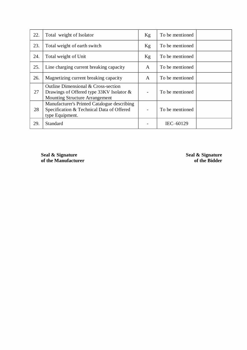
22. Total weight of Isolator Kg To be mentioned
23. Total weight of earth switch Kg To be mentioned

24. Total weight of Unit Kg To be mentioned
25. Line charging current breaking capacity A To be mentioned
26. Magnetizing current breaking capacity A To be mentioned
27
Outline Dimensional & Cross-section
Drawings of Offered type 33KV Isolator &
Mounting Structure Arrangement
- To be mentioned
28
Manufacturer's Printed Catalogue describing
Specification & Technical Data of Offered
type Equipment.
- To be mentioned
29. Standard - IEC–60129
Seal & Signature
of the Manufacturer
Seal & Signature
of the Bidder

C.8.6: TECHNICAL PARTICULARS AND GUARANTEES OF33 KV OFF-LOAD ISOLATOR (800A)
WITHOUT EARTH BLADE
(To be filled up by the Manufacturer, otherwise the bid shall not be considered for evaluation)
Sl.
No. Description Unit
BPDB's Requirement
Manufacturer's
guaranteed
Particulars
1. Manufacturer’s Name and country - To be mentioned
2. Manufacturer’s Model no. - To be mentioned
3. Frequency Hz 50
4. System Nominal Voltage KV 33
5. System Maximum Voltage KV 36
6. Basic Insulation Level KV 170
7. Rated Normal Current A 800
8. Rated short time withstand current (for 3sec.) KA 25
9. Installation - Outdoor
10. Type - Air
11. Construction - Open
12. Operation - Gang
13. Operating Mechanism - Manual
14. Mounting Position - Vertical
15. Number of Pole nos. 3 (Three)
16. No. of break per pole nos. To be mentioned
17. Contract Resistance (μΩ) & Contact Area
(mm2)
- To be mentioned
18. Materials of contact service - To be mentioned
19. Nos. of Auxiliary Contracts (NO/NC) -
To be mentioned
20. Air gap between pole of phase mm To be mentioned
21. Creepage distance of Insulator mm To be mentioned
22. Total weight of Unit Kg To be mentioned
23. Line charging current breaking capacity A To be mentioned
24. Magnetizing current breaking capacity A To be mentioned

25.
Outline Dimensional & Cross-section
Drawings of Offered type 33KV Isolator &
Mounting Structure Arrangement
- To be mentioned
26.
Manufacturer's Printed Catalogue describing
Specification & Technical Data of Offered
type Equipment.
- To be mentioned
27. Standard - IEC–60129
Seal & Signature
of the Manufacturer
Seal & Signature
of the Bidder

C.8.7: TECHNICAL PARTICULARS AND GUARANTEES OF 33 KV OFF-LOAD ISOLATOR
(1250A) WITHOUT EARTH BLADE
(To be filled up by the Manufacturer, otherwise the bid shall not be considered for evaluation)
Sl.
No. Description Unit
BPDB's
Requirement
Manufacturer's
guaranteed
Particulars
1. Manufacturer’s Name and country - To be mentioned
2. Manufacturer’s Model no. - To be mentioned
3. Frequency Hz 50
4. System Nominal Voltage KV 33
5. System Maximum Voltage KV 36
6. Basic Insulation Level KV 170
7. Rated Normal Current A 1250
8. Rated short time withstand current (for 3sec.) KA 25
9. Installation - Outdoor
10. Type - Air
11. Construction - Open
12. Operation - Gang
13. Operating Mechanism - Manual
14. Mounting Position - Vertical
15. Number of Pole nos. 3 (Three)
16. No. of break per pole nos. To be mentioned
17. Contract Resistance (μΩ) & Contact Area
(mm2)
- To be mentioned
18. Materials of contact service - To be mentioned
19. Nos. of Auxiliary Contracts (NO/NC) -
To be mentioned
20. Air gap between pole of phase mm To be mentioned
21. Creepage distance of Insulator mm To be mentioned
22. Total weight of Unit Kg To be mentioned
23. Line charging current breaking capacity A To be mentioned
24. Magnetizing current breaking capacity A To be mentioned

25.
Outline Dimensional & Cross-section
Drawings of Offered type 33KV Isolator &
Mounting Structure Arrangement
- To be mentioned
26.
Manufacturer's Printed Catalogue describing
Specification & Technical Data of Offered
type Equipment.
- To be mentioned
27. Standard - IEC–60129
Seal & Signature
of the Manufacturer
Seal & Signature
of the Bidder

C.8.8:TECHNICAL PARTICULARS AND GUARANTEES OF 33 KV OFF-LOAD
FUSED ISOLATOR FOR AUXILIARY TRANSFORMER
(To be filled up by the Manufacturer in Manufacturer Letterhead Pad, otherwise the bid shall be rejected)
Sl.
No. Description Unit BPDB's Requirement
Manufacturer's
Guaranteed
Particulars
1 Manufacturer's Name & country - To be mentioned
2 Manufacturer's Model No. - To be mentioned
3 Application - 33/0.4kV Auxiliary Transformer
4 Installation - Outdoor Substation
5 Type -
Rewireable enclosed expulsion
liquid filled, Fuse-isolator with
arcing horn/HRC Power fuse
6 Operation mechanism - Manual
7 Operation - Gang
8 Base mounting position - Vertical
9 Number of poles - 3 (three)
10 System frequency Hz 50 Hz
11 Rated voltage kV 33/0.4kV Auxliary Transformer
12 Rated normal current A 400 Amperes
13 Rated short time current kA 25 kA (3 sec.)
14 Maximum ambient temperature 0C 450C
15 Rated fuse link normal current A 200 Amperes
16 Rated fuse link interrupting current kA 36kA, RMS Symmetrical
17 Fuse link type No Two element, slow/fast unit
18 Fuse holder type - Heavy duty, sealed cap with eye at
both ends of fuse holder
19 Fuse link co-ordination - Shall co-ordinate with existing
system protective equipment
20 Basic insulation level (min) kV 170 kV
21 Type of operating mechanism - To be mentioned
22 Total weight of unit Kg To be mentioned
23 Line charging current breaking
capacity A To be mentioned
24 Magnetising current breaking capacity A To be mentioned
25 Standard -
Performance, design & testing shall
be in accordance to latest revision of
BS-5253 or IEC-129 or equivalent
International Standards unless
otherwise specified herein.
Seal & Signature of the Bidder
Seal & Signature of
the Manufacturer

C.8.9:TECHNICAL PARTICULARS AND GUARANTEES OF 33 KV OFF-LOAD
FUSED ISOLATOR FOR BUS PT
(To be filled up by the Manufacturer in Manufacturer Letterhead Pad, otherwise the bid shall be rejected)
Sl.
No. Description Unit BPDB's Requirement
Manufacturer's
Guaranteed
Particulars
1 Manufacturer's Name & country - To be mentioned
2 Manufacturer's Model No. - To be mentioned
3 Application - 33kV Bus PT
4 Installation - Outdoor Substation
5 Type -
Rewireable enclosed expulsion
liquid filled, Fuse-isolator with
arcing horn/HRC Power fuse
6 Operation mechanism - Manual
7 Operation - Gang
8 Base mounting position - Vertical
9 Number of poles - 3 (three)
10 System frequency Hz 50 Hz
11 Rated voltage kV 33kV Transformer
12 Rated normal current A 400 Amperes
13 Rated short time current kA 25 kA (3 sec.)
14 Maximum ambient temperature 0C 450C
15 Rated fuse link normal current A 200 Amperes
16 Rated fuse link interrupting current kA 36kA, RMS Symmetrical
17 Fuse link type No Two element, slow/fast unit
18 Fuse holder type - Heavy duty, sealed cap with eye at
both ends of fuse holder
19 Fuse link co-ordination - Shall co-ordinate with existing
system protective equipment
20 Basic insulation level (min) kV 170 kV
21 Type of operating mechanism - To be mentioned
22 Total weight of unit Kg To be mentioned
23 Line charging current breaking
capacity A To be mentioned
24 Magnetising current breaking capacity A To be mentioned
25 Standard -
Performance, design & testing shall
be in accordance to latest revision of
BS-5253 or IEC-129 or equivalent
International Standards unless
otherwise specified herein.
Seal & Signature of the Bidder
Seal & Signature of
the Manufacturer

C.8.10:GUARANTEED TECHNICAL PARTICULARS OF 33 KV OUTDOOR TYPE
SINGLE PHASE CURRENT TRANSFORMER
(To be filled up by Manufacturer Letterhead Pad, otherwise the bid shall not be considered for evaluation)
Sl.
No. Description Unit BPDB's Requirement
Manufacturer's
Guaranteed Particulars
1 Manufacturer's Name & Country - To be mentioned
2 Manufacturer's Model No. - To be mentioned
3 Application - Metering and Protection
4 Type - Induction
5 Installation - Outdoor
6 Construction - Sealed Tank
7 Insulation - Oil
8 Number of Phase - Single
9 Rated Frequency Hz 50
10 Mounting - On Supporting Structure
11 Primary rated voltage (Phase to Phase) kV 33
12 Maximum System Voltage (Phase to Phase)
kV 36
13 System Earthing - Effectively Earthed
14 Basic Insulation Level (1.2/50 Micro-Sec.) kV 170
15 Power frequency withstand voltage (1 Min.
50 Hz.) kV 70
16 Ratio:
For 33/11kV, 5/6.67 MVA Power
Transforment Incoming & 33kV Outgoing
feeder
200-400/5-5A
For 33kV Line Feeder Incoming 200-400/5-5A
17 Type of Winding:
a) Primary - Single Winding
b) Secondary - Double winding
18 Accuracy Class:
a) for measurement - 0.2
b) for Protection - 5P20
19 Burden:
a) for measurement VA 20
b) for Protection VA 20
20 Short Time Current Rating for 3 Sec. kA 25
21 Extended Current Rating (% of rated
current) % 120
22 Over Current Rating A <10
23 Creepage Distance
mm/k
V
(Min.)
25
24 Rated accuracy limit factor - To be mentioned
25 Knee point voltage V To be mentioned
26 Bushing - Porcelain outdoor type
27 Standard - IEC 60044-1
Seal & Signature
of the Manufacturer
Seal & Signature
of the Bidder

C.8.11:TECHNICAL PARTICULARS AND GUARANTEES OF 33 KV OUTDOOR TYPE
SINGLE PHASE POTENTIAL TRANSFORMER
(To be filled up by Manufacturer Letterhead Pad, otherwise the bid shall not be considered for evaluation)
Sl.
No.
Description Unit BPDB's
Requirement
Manufacturer's
Guaranteed Particulars
1 Manufacturer's Name & Country or
origin
- To be mentioned
2 Manufacturer's Model No. - To be mentioned
3 Type - Induction Type
4 Ratio V 33000/√3:110/√3:110
/√3
5 No. of phase Nos. Single Phase
6 Total capacitance at 100 Hz PF To be mentioned
7 50 Hz 1 (One) minute withstand
voltage wet
KV To be mentioned
8 Impulse withstand (1.2/50 micro sec.
wave)
KV 170
9 Rated burden per phase VA 50+50
10 Class of accuracy - 0.2+3P
11 Temperature co-efficient of ratio per 0C
- To be mentioned
12 System earthing - Effectively Earthed
13 Creepage Distance mm/kV 25 (min)
14 Maximum errors with 5% primary voltage:
a) Ratio % To be mentioned
b) Phase angle minutes To be mentioned
15 Total weight complete Kg To be mentioned
16 Standard - As per relevant IEC
60044-2
Seal & Signature of the Manufacturer
Seal & Signature
of the Bidder

C.8.13:Guaranteed Technical Particulars for ACSR GROSBEAK
(To be filled up by the Manufacturer in Manufacturer's Letterhead Pad with appropriated data)
Sl.
No. Description Unit Purchaser’s
Requirement Manufacturer’s
Particulars 1 Name of the Item ACSR GROSBEAK
2 Name of the Manufacturer Shall be mentioned 3 Address of the Manufacturer Shall be mentioned 4 Standard Performance Design and
Testing shall be in accordance to the BS,
IEC, ASTM, BDS or
equivalent International standards.
5 Installation Overhead 6 Type Stranded 7 Material Hard drawn Aluminium
steel reinforced
8 Overall diameter mm 25.15 9 Nominal cross sectional area of
conductor mm
2 374.70
10 Number/diameter of Aluminium
Strand No./m
m 26/3.97
11 Nominal Aluminium cross
sectional area mm
2 321.68
12 Number/diameter of Steel Strand No./m
m 7/3.09
13 Nominal Steel cross sectional
area mm
2 53.02
14 Weight of conductor Kg/K
M 1304
15 Drum wound length M 500 16 Net weight Kg Shall be mentioned 17 Gross weight Kg Shall be mentioned 18 Maximum DC Resistance of
Conductor at 20 °C /KM 0.0900
19 Minimum breaking Load of Conductor
Kg 11400
20 Maximum working tension of
conductor KN Shall be mentioned
21 Current rating at 35ºC rise over 40ºC ambient temperature (75ºC)
Amps. 538 (min)
22 Practical (final) modulus of
elasticity hbar 7700
23 Co-efficient of linear expansion /ºC 18.9 x 10⁻⁶
24 Aluminum to Steel Ratio Shall be mentioned 25 Lay length for Outermost Layer
of Aluminium mm Shall be mentioned
26 Lay direction for Outermost
Layer of Aluminium Right hand
27 Lay ratio for Outermost Layer of Aluminium
10-14
28 Treated Wooden Drum Standard AWPA C1 – 82, C2 –83, C16 –82, P5 –83.
Seal and Signature of the manufacturer:
Seal and Signature of the Bidder:

C.8.14.1:Guaranteed Technical Particulars for Disc Insulator
(To be filled up by the Manufacturer in Manufacturer's Letterhead Pad with appropriated data)
Sl.
No. Description Purchaser's
Requirement Manufacturer's
Particulars 01. Name of the Item Disc Insulator
02. Name of Manufacturer &
Address Shall be mentioned
03. Manufacturer’s Code No. To be mentioned 04. Standard Performance, Design and
Testing shall be in accordance to the BS, IEC,
ASTM, BDS or equivalent
International standards.
05. Installation Overhead 06. Type Disc 07. Material Porcelain 08. Creepage Distance 292 mm 09. Flash over voltage
Power Frequency, Dry Power Frequency, Wet
78 kV 45 kV
10. Withstand Voltage Power Frequency, Dry Power Frequency, Wet
70 kV 40 kV
11. Power Frequency Puncture
Voltage 110 kV
12. 50% Impulse flashover
Positive 120 kV
13. 50% Impulse flashover
Negative 125 kV
14. Mechanical Failing Load 70 KN 15. Nominal Diameter 255 mm 17. Minimum Spacing 146 mm 18 Dry Arching Distance
minimum 171 mm
19 Coupling Size 16 mm 20 Weight in Kg To be mentioned
Seal and Signature of the manufacturer:
Seal and Signature of the Bidder:

C.8.14.2:Guaranteed Technical Particulars of 33 KV Bus bar insulator string
(To be filled up by the Manufacturer in Manufacturer Letterhead with appropriate data)
Sl. No. Description Unit BPDB's
Requirement
Manufacturer's
guaranteed Particulars
1 Manufacturer’s Name & Country - To be mentioned
2 Manufacturer’s model no. - To be mentioned
3 Insulator material - Porcelain
4 Number of units per string Nos. 4
5 Insulator Voltage Class KV 15
6 Insulator Materials Porcelain
7 Type of Insulator - Ball and socket type disc, security clip made of rod
brass alloy.
8 Creepage/ leakage distance (min.) mm 298
9 Total creepage distance of string mm 850
10 Unit Spacing mm 146
11 Dry Arcing distance (minimum) mm 1968
12 Diameter of Insulator mm 256
13 Withstand Voltage, Minimum :
a) Power Frequency, dry (one min.) KV 70 b) Power Frequency, wet (one min.) KV 40 c) Impulse 1.2/50 sec KV 110
14 Flashover Voltage, Minimum : a) Power Frequency, dry KV 80 b) Power Frequency, wet KV 50 c) 50% Impulse 1.2/50 sec wave,
positive or impulse 1.2/50 sec wave
positive.
KV 125
d) 50% Impulse 1.2/50 sec wave
Negative
KV 130
15 Power Frequency Puncture Voltage, minimum
KV 110
16 Radio Influence Voltage Data, minimum a) Power frequency test voltage RMS to
Ground KV 10
b) Maximum RIV at 1,000 Kc V 50
17 Minimum Mechanical Strength for Suspension :
a) Electro-mechanical Breaking Load Kg 7260
b) Mechanical Breaking load Kg 6800
c) Tension Proof Test Load Kg 3400
d) Time Load Test Value Kg 4536
e) Mechanical Impact Strength mm Kg 630
18 Minimum Mechanical Strength for Strain Stringing :
a) Electro-mechanical Breaking Load Kg 11340
b) Mechanical Breaking load Kg 11340
c) Tension Proof Test Load Kg 3400
d) Time Load Test Value Kg 4536
e) Mechanical Impact Strength mm Kg 530
19 Insulator Hardware Insulator hardware for insulator strings or bus-support such shall have UTS-120 KN and galvanized as per
BS-729 OR ASTM A-153.
20 Standard AS per latest editions of IEC-383.
Seal & Signature
ofthe Manufacturer
Seal & Signature
of the Bidder

C.8.15.1 Guaranteed Technical Particulars for H-Type Connector
(To be filled up by the Manufacturer in Manufacturer's Letterhead Pad with appropriated data)
Sl.
No. Description Purchaser’s
Requirement Manufacturer’s
Particulars
Compatible for ACSR GROSBEAK to ACSR GROSBEAK
1. Name & Address of the
Manufacturer Shall be mentioned
2. Manufacturer’s Code No. Shall be mentioned
3. Applicable Standard Design, Testing & Performance
shall be in accordance to BS,
IEC, BDS, ANSI, ASTM or equivalent international
standards.
4. Installation Outdoor and shall be installed
for the above-mentioned conductor.
5. Type H-Type 6. Material Aluminum 7. Minimum Continuous Current
rating at 35ºC rise over 40ºC
ambient temperature (75ºC)
538 Amps (min).
8. Length 150 mm (min) 9. Weight of 100 nos. in Kg Shall be mentioned
Seal and Signature of the manufacturer:
Seal and Signature of the Bidder:

C.8.15.2 Guaranteed Technical Particulars for H-Type Connector
(To be filled up by the Manufacturer in Manufacturer's Letterhead Pad with appropriated data)
Sl. No.
Description Purchaser’s Requirement
Manufacturer’s Particulars
Compatible for ACSR MERLIN to ACSR MERLIN
1. Name & Address of the Manufacturer
Shall be mentioned
2. Manufacturer’s Code No. Shall be mentioned
3. Applicable Standard Design, Testing & Performance shall be in accordance to BS, IEC, BDS, ANSI, ASTM or equivalent international standards.
4. Installation Outdoor and shall be installed for the above-mentioned conductor.
5. Type H-Type 6. Material Aluminium 7. Minimum Continuous Current
rating at 35ºC rise over 40ºC ambient temperature (75ºC)
362 Amps (min).
8. Length 112 mm 9. Weight of 100 nos. in Kg Shall be mentioned
Seal and Signature of the manufacturer:
Seal and Signature of the Bidder:

C.8.16:Guaranteed Technical Particulars for Guy/Earth Wire.
(To be filled up by the Manufacturer in Manufacturer's Letterhead Pad with appropriated data)
Sl.
No. Description Unit Purchaser's
Requirement Manufacturer’s
Particulars 1 Name of the Item Guy/Earth Wire 2 Name &v Address of the
Manufacturer Shall be mentioned
3 Manufacturer's Code No. Shall be mentioned 4 Standard Performance Design
and Testing shall be in
accordance to the BS,
BDS or equivalent
International standards.
5 Installation Overhead/Stay 6 Type Stranded, Solid and
Bare
7 Material High Strength Steel 8 Overall diameter Mm 9.50 9 Number/diameter of each strand No./mm 7/3.15 10 Nominal cross sectional area of
conductors mm
2 54.53
11 Weight of Guy Wire Kg/KM 430 12 Ultimate Tensile Strength
KN 62.75
13 Galvanisation As per ASTM B498-
74, Class-A
14 Modulus of Elasticity
Kg/mm
2 19.7 x 10³
15 Coefficient of linear expansion
/ºC 11.3 x 10⁻⁶
16 Drum wound length M 1500 17 Net weight Kg Shall be mentioned 18 Gross weight Kg Shall be mentioned 19 Lay length Mm Shall be mentioned 20 Lay direction Right hand 21 Lay ratio 13-18 22 Treated Wooden Drum Standard AWPA C1 – 82, C2 –
83, C16 –82, P5 –83.
Seal and Signature of the manufacturer:
Seal and Signature of the Bidder:

C.8.17.1Guaranteed Technical Particulars for PG Clamp
(To be filled up by the Manufacturer in Manufacturer's Letterhead Pad with appropriated data)
Sl. No.
Description Purchaser’s Requirement
Manufacturer’s Particulars
Compatible for ACSR GROSBEAK to ACSR GROSBEAK
1. Name & Address of the Manufacturer
Shall be mentioned
2. Manufacturer’s Code No. Shall be mentioned
3. Applicable Standard Design, Testing & Performance shall be in accordance to BS, IEC, BDS, ANSI, ASTM or equivalent international standards.
4. Installation Outdoor and shall be installed for the above-mentioned conductor.
5. Type Bolted Type 6. Material Aluminium Alloy 7. Minimum Continuous Current
rating at 35ºC rise over 40ºC ambient temperature (75ºC)
628 Amps (min).
8. Dimension 125 mm x 50 mm 9. Weight of 100 nos. in Kg Shall be mentioned
Seal and Signature of the manufacturer:
Seal and Signature of the Bidder:

C.8.17.2Guaranteed Technical Particulars for PG Clamp
(To be filled up by the Manufacturer in Manufacturer's Letterhead Pad with appropriated data)
Sl. No.
Description Purchaser’s Requirement
Manufacturer’s Particulars
Compatible for ACSR MERLIN to ACSR MERLIN
1. Name & Address of the Manufacturer
Shall be mentioned
2. Manufacturer’s Code No. Shall be mentioned
3. Applicable Standard Design, Testing & Performance shall be in accordance to BS, IEC, BDS, ANSI, ASTM or equivalent international standards.
4. Installation Outdoor and shall be installed for the above-mentioned conductor.
5. Type Bolted Type 6. Material Aluminium Alloy 7. Minimum Continuous Current
rating at 35ºC rise over 40ºC ambient temperature (75ºC)
362 Amps (min).
8. Dimension 110 mm x 45 mm 9. Weight of 100 nos. in Kg Shall be mentioned
Seal and Signature of the manufacturer:
Seal and Signature of the Bidder:

C.8.19Guaranteed Technical ParticularsOF 11 KV ISOLATOR (800A) WITH EARTH BLADE
(To be filled up by the Manufacturer, otherwise the bid shall not be considered for evaluation)
Sl.
No. Description Unit
BPDB's Requirement
Manufacturer's
guaranteed
Particulars
1. Manufacturer’s Name and country - To be mentioned
2. Manufacturer’s Model no. - To be mentioned
3. Frequency Hz 50
4. System Nominal Voltage KV 11
5. System Maximum Voltage KV 12
6. Basic Insulation Level KV 75
7. Rated Normal Current A 800
8. Rated short time withstand current (for 3sec.) KA 25
9. Installation - Outdoor
10. Type - Air
11. Construction - Open
12. Operation - Gang
13. Operating Mechanism - Manual
14. Mounting Position - Vertical
15. Number of Pole nos. 3 (Three)
16. No. of break per pole nos. To be mentioned
17.
Contract Resistance (μΩ) & Contact Area
(mm2)
i) Isolator
ii) Earthblade
- To be mentioned
18. Materials of contact service - To be mentioned
19.
Nos. of Auxiliary Contracts (NO/NC)
i) Isolator
ii) Earthblade
- To be mentioned
20. Air gap between pole of phase mm To be mentioned
21. Creepage distance of Insulator mm To be mentioned
22. Total weight of Isolator Kg To be mentioned
23. Total weight of earth switch Kg To be mentioned
24. Total weight of Unit Kg To be mentioned
25. Line charging current breaking capacity A To be mentioned
26. Magnetizing current breaking capacity A To be mentioned
27
Outline Dimensional & Cross-section
Drawings of Offered type 33KV Isolator &
Mounting Structure Arrangement
- To be mentioned
28
Manufacturer's Printed Catalogue describing
Specification & Technical Data of Offered
type Equipment.
- To be mentioned
29. Standard - IEC–60129
Seal & Signature
of the Manufacturer
Seal & Signature
of the Bidder

C.8.20:GUARANTEED TECHNICAL PARTICULARS OF 11KV ISOLATOR (800A) WITHOUT
EARTH BLADE
(To be filled up by the Manufacturer, otherwise the bid shall not be considered for evaluation)
Sl.
No. Description Unit
BPDB's
Requirement
Manufacturer's
guaranteed
Particulars
1. Manufacturer’s Name and country - To be mentioned
2. Manufacturer’s Model no. - To be mentioned
3. Frequency Hz 50
4. System Nominal Voltage KV 11
5. System Maximum Voltage KV 12
6. Basic Insulation Level KV 75
7. Rated Normal Current A 800
8. Rated short time withstand current (for 3sec.) KA 25
9. Installation - Outdoor
10. Type - Air
11. Construction - Open
12. Operation - Gang
13. Operating Mechanism - Manual
14. Mounting Position - Vertical
15. Number of Pole nos. 3 (Three)
16. No. of break per pole nos. To be mentioned
17. Contract Resistance (μΩ) & Contact Area
(mm2)
- To be mentioned
18. Materials of contact service - To be mentioned
19. Nos. of Auxiliary Contracts (NO/NC) -
To be mentioned
20. Air gap between pole of phase mm To be mentioned
21. Creepage distance of Insulator mm To be mentioned
22. Total weight of Unit Kg To be mentioned

23. Line charging current breaking capacity A To be mentioned
24. Magnetizing current breaking capacity A To be mentioned
25.
Outline Dimensional & Cross-section
Drawings of Offered type 33KV Isolator &
Mounting Structure Arrangement
- To be mentioned
26.
Manufacturer's Printed Catalogue describing
Specification & Technical Data of Offered
type Equipment.
- To be mentioned
27. Standard - IEC–60129
Seal & Signature
of the Manufacturer
Seal & Signature
of the Bidder

C.8.21 GUARANTEED TECHNICAL PARTICULARSof 11KV Off Load BUS SECTION
Isolator (1250A) without Earth Blade
(To be filled up by the Manufacturer, otherwise the bid shall not be considered for evaluation)
Sl.
No. Description Unit
BPDB's
Requirement
Manufacturer's
guaranteed
Particulars
1. Manufacturer’s Name and country - To be mentioned
2. Manufacturer’s Model no. - To be mentioned
3. Frequency Hz 50
4. System Nominal Voltage KV 11
5. System Maximum Voltage KV 12
6. Basic Insulation Level KV 75
7. Rated Normal Current A 1250
8. Rated short time withstand current (for 3sec.) KA 25
9. Installation - Outdoor
10. Type - Air
11. Construction - Open
12. Operation - Gang
13. Operating Mechanism - Manual
14. Mounting Position - Vertical
15. Number of Pole nos. 3 (Three)
16. No. of break per pole nos. To be mentioned
17. Contract Resistance (μΩ) & Contact Area
(mm2)
- To be mentioned
18. Materials of contact service - To be mentioned
19. Nos. of Auxiliary Contracts (NO/NC) -
To be mentioned
20. Air gap between pole of phase mm To be mentioned
21. Creepage distance of Insulator mm To be mentioned
22. Total weight of Unit Kg To be mentioned

23. Line charging current breaking capacity A To be mentioned
24. Magnetizing current breaking capacity A To be mentioned
25.
Outline Dimensional & Cross-section
Drawings of Offered type 33KV Isolator &
Mounting Structure Arrangement
- To be mentioned
26.
Manufacturer's Printed Catalogue describing
Specification & Technical Data of Offered
type Equipment.
- To be mentioned
27. Standard - IEC–60129
Seal & Signature
of the Manufacturer
Seal & Signature
of the Bidder

C.8.22GUARANTEED TECHNICAL PARTICULARS & GUARANTEES OF 11 KV, 630Amps
AUTO CIRCUIT RECLOSERS
(To be filled up by the Manufacturer in the Manufacturer Letterhead Pad with appropriate data)
SL. No.
Description BPDB Requirement Manufacturer’ guaranteed
technical particulars
1 Manufacturer’s name and
Address To be mentioned
2 Country of Origin To be mentioned
3 Type and Model To be mentioned
4
Reference/Design
standard(BS/IEC or
ANSI/IEEE C37.60)
To be mentioned
5 Catalogue no. of proposed
item To be mentioned
6 Interrupting medium Vacuum
7 Control System Electronic
8 Ground trip mechanism Electronic
9 Insulating Medium SF6/ Vacuum Type
10 Nominal System voltage 11 kV
11 Maximum Voltage 15 kV
12 BIL 110 kV
13 Rated Frequency 50 Hz
14 Power frequency withstand
voltage 50 kV
15 Rated Continuous Current 630 Amps
16 Maximum Rated Current 630 Amps
17 Symmetrical Interrupting
Current 12,500 Amps
18 Symmetrical Making
Current 31,250 Amps
19 Rated Minimum Tripping
Current
Phase : 50 ~ 630 Amps
Ground : 50 Amps
20 Break Contact Structure Single Break
21 No. of fast Operation 0 to 4
22 No. of delayed operation 0 to 4

SL. No.
Description BPDB Requirement Manufacturer’ guaranteed
technical particulars
23 No. of operations to lockout 1,2,3 or 4(depending on setting)
24 Reclosing Time Interval Adjustable 0.6 to 1000 sec
25 Resetting time Adjustable 2 ~ 120 sec
26 Provision for three phase
Amp. Measurement Ammeter for phase
current measurement
27 Co-
ordinationCapability(TCC
Curves)
To be mentioned standard
inverse, very inverse and
extremely inverse curve
28 Recloser Head Corrosion resistance material
29 Recloser tank Corrosion resistance steel
30 Recloser bushing Polymer bushing with bird
guard
31 Operations Counter Shall indicate total operation
32 Manual Operating
Provision & Lockout
Indicator Shall be provided
33 Protection & Metering CT
ratio To be mentioned
34 Connector
Universal clamp to
accommodate 6 AWG to 350 MCM Cu or
Aluminum
35 Provision for different trip current setting
Without changing CT’s or without untanking
36 Cable for control/meter box 10 meter control cable
shall be provided
37 Gas pressure indicator Shall be included
38 Sub-station mounting
Structure/frame Shall be provided
39 Design & Product test Shall be submitted as per
tender
40 Fault Locator feature(in
control panel) Yes/No
41 Capacitor Voltage Divider
Input available Yes/No
42 Battery Nominal Voltage To be mentioned

Manufacturer’s seal & signature Bidder’s seal & signature
SL. No.
Description BPDB Requirement Manufacturer’ guaranteed
technical particulars
43 Nominal Capacity(Ah) of
Battery To be mentioned
44 Self discharge Versus
Time(Battery) To be mentioned
45 Service Life Time(Battery)
To be mentioned
46 Auxiliary Input Voltage
220 V

C.8.23TECHNICAL PARTICULARS AND GUARANTEES OF11 KV OUTDOOR TYPE
SINGLE PHASE CURRENT TRANSFORMER
(To be filled up by Manufacturer Letterhead Pad, otherwise the bid shall not be considered for evaluation)
Sl.
No. Description Unit
BPDB’s
Requirement
Manufacturer’s Guaranteed
Particulars
1 Manufacturers Name & Country - To be mentioned
2 Manufacturer Model No. - To be mentioned
3 Application - Metering and
Protection
4 Type - Induction
5 Installation - Outdoor
6 Construction - Sealed Tank
7 Insulation - Oil
8 Number of phase Single
9 Rated frequency Hz 50
10 Mounting - On Supporting
Structure
11 Primary rated voltage (Phase to
Phase) kV 11
12 Maximum System Voltage (Phase to Phase)
kV 12
13 System earthing - Effectively earthed
14 Basic insulation Level (1.2/50
Micro-sec) kV 75
15 Power frequency withstand
voltage (1 min 50 Hz) kV 28
16 Cross sectional area of Primary
Terminals mm2 To be mentioned
17 CT Ratio:
200-400/5-5A - 200-400/5-5A
18
Type of winding
a) Primary - Single winding
b) Secondary - Double winding
19
Accuracy Class
a) for measurement - 0.2
b) for Protection 5P15
20
Burden
a) for measurement VA 15
b) for Protection VA 15
21 Short time Current rating for 3
sec. KA 25
22 Extended Current Rating (% of
rated current) % 120
23 Over Current rating A < 10
24 Creepage Distance (minm) mm/KV 25
25 Rated accuracy limit factor
(ALF) - To be mentioned
26 Standard - As per relevant
IEC-60044-1
Seal & Signature
of the Manufacturer
Seal & Signature
of the Bidder

C.8.24Guaranteed Technical Particulars of 11KV Single Phase Lightning Arrester
(To be filled up by the Manufacturer in Manufacturer Letterhead Pad, otherwise the bid shall be rejected)
Sl.
No. Description Unit
BPDB's
Requirement
Manufacturer's
Guaranteed
Particulars
01 Manufacturer’s Name and Country - To be mentioned
02 Manufacturer’s model No. - To be mentioned
03 Type of the Arrester - Metal Oxide
(ZnO), Gapless
04 Rated Arrester Voltage kV 10.5
05 Rated Arrester Current KA 5
06 Max. Continuous Operating Voltage kV rms 8.4
07 Power Frequency withstand voltage of the
Arrester Housing, Dry & Wet kV rms 35 (Dry) &
30 (Wet)
08 Impulse withstand Voltage of the Arrester
Housing. kV (peak) 75
09 Lightning Impulse Residual Voltage (8/20
micro-second wave) kV (peak) 35
10 Steep Current Impulse Residual Voltage
at 10 KA of 1 micro second front time. kV (peak) 40
11 High Current Impulse Withstand Value
(4/10 micro second) KA 65
12 Temporary Over voltage capability:
a) 0.1 Second kV (peak) To be mentioned
b) 1.0 Second kV (peak) To be mentioned
c) 10 Second kV (peak) To be mentioned
d) 100 Second kV (peak) To be mentioned
13 Leakage Current at rated voltage mA < 1 mA
14 Total Creepage distance (minimum) mm/ kV 25
15 Overall dimension :
a) Height mm To be mentioned
b) Diameter mm To be mentioned
16 Total weight of Arrester Kg. To be mentioned
17 Outline dimensional drawing of offered
LA and mounting Bracket. - To be Submitted
18 Printed catalogue describing specification,
technical data of LA
- To be Submitted
19 Manufacturer's ISO 9001 certificate. - To be Submitted
20 Standard - IEC-99-4/
ANSI- C 62.11
Seal & Signature
of the Manufacturer
Seal & Signature
of the Bidder

C.8.25:TECHNICAL PARTICULARS AND GUARTANTEES OF11 KV OUTDOOR
TYPE SINGLE PHASE POTENTIAL TRANSFORMER
(To be filled up by Manufacturer Letterhead Pad, otherwise the bid shall not be considered for evaluation)
Sl.
No. Description Unit BPDB’s Requirement
Manufacturer’s
Guaranteed
Particulars
1 Manufacturers Name
& Country of origin - To be mentioned
2 Manufacturer Model
No. - To be mentioned
3 Type - Induction Type
4 Construction - Oil Tank
5 Sealed Oil Tank Yes/No To be mentioned
6 Ratio V (11000/√3)/(110/√3)/(110/√3)
7 No. of phase Nos. Single Phase
8 Total capacitance at
100 Hz PF To be mentioned
9 50 Hz 1(one) minute
withstand voltage wet kV To be mentioned
10
Impulse withstand
(1.2/50 micro sec
wave)
kV 75
11 Rated burden per
phase VA (50+50)
12
Class of accuracy
a) Metering
b) Protection
-
0.2
13
Temperature co-
efficient of ratio per 0C
- To be mentioned
14 System earthing - Effectively earthed
15 Creepage distance mm/kV 25 (Min)
16
Maximum errors with
5% primary voltage
a) Ratio % To be mentioned
b) Phase angle Minutes To be mentioned
17 Total weight complete Kg To be mentioned
18 Standard - As per relevant IEC-60044-2
Seal & Signature
of the Manufacturer
Seal & Signature
of the Bidder

C.8.27:TECHNICAL PARTICULARS AND GUARANTEES OF 11 KV OFF- LOAD
FUSED ISOLATOR FOR BUS PT
(To be filled up by the Manufacturer in Manufacturer Letterhead Pad, otherwise the bid shall be rejected)
Sl.
No. Description Unit BPDB's Requirement
Manufacturer's
Guaranteed
Particulars
1 Manufacturer's Name & country - To be mentioned
2 Manufacturer's Model No. - To be mentioned
3 Application - 11kV Bus PT
4 Installation - Outdoor Substation
5 Type -
Rewireable enclosed expulsion
liquid filled, Fuse-isolator with
arcing horn/HRC Power fuse
6 Operation mechanism - Manual
7 Operation - Gang
8 Base mounting position - Vertical
9 Number of poles - 3 (three)
10 System frequency Hz 50 Hz
11 Rated voltage kV 11KV bus PT
12 Rated normal current A 400 Amperes
13 Rated short time current kA 25 kA (3 sec.)
14 Maximum ambient temperature 0C 450C
15 Rated fuse link normal current A 200 Amperes
16 Rated fuse link interrupting current kA 12kA, RMS Symmetrical
17 Fuse link type No Two element, slow/fast unit
18 Fuse holder type - Heavy duty, sealed cap with eye at
both ends of fuse holder
19 Fuse link co-ordination - Shall co-ordinate with existing
system protective equipment
20 Basic insulation level (min) kV 170 kV
21 Type of operating mechanism - To be mentioned
22 Total weight of unit Kg To be mentioned
23 Line charging current breaking
capacity A To be mentioned
24 Magnetizing current breaking capacity A To be mentioned
25 Standard -
Performance, design & testing shall
be in accordance to latest revision of
BS-5253 or IEC-129 or equivalent
International Standards unless
otherwise specified herein.
Seal & Signature of the Bidder
Seal & Signature of
the Manufacturer

C.8.28:GUARANTEED TECHNICAL PARTICULARS AND GUARANTEES OF 11 KV BUS BAR & JUMPER
(To be filled up by the Manufacturer in Manufacturer Letterhead Pad with appropriate datauation)
Sl. No. Description Unit BPDB's
Requirement
Manufacturer's
guaranteed
Particulars
1 Manufacturer’s Name and country - To be mentioned
2 Material (conductor)
a) Bus bars - ACSR MARTIN
b) Jumper/ connections - HAWK/
GROSBEAK
3 Overall diameter mm To be mentioned
4 Nominal cross section mm2 To be mentioned
5 Cross section and make –up - To be mentioned
6 Maximum rated current A To be mentioned
7 Maximum working tension of main
connections
Kg/m2 To be mentioned
8 DC Resistance of conductors per 1000 meters at
20 0C
Ohms To be mentioned
9 Tensile breaking stress of material N/ mm2 To be mentioned
10 Maximum permissible span length m To be mentioned
11 Maximum sag under own weight of
maximum span
mm To be mentioned
Seal & Signature of the Manufacturer Seal & Signature of the Bidder

C.8.29Guaranteed Technical Particulars for Single-Core, 95 mm2PVC Insulated
andPVC Sheathed Copper Cable.
(To be filled up by the Manufacturer in Manufacturer's Letterhead Pad with appropriated data) Sl. No.
Description Unit Purchaser’s Requirement
Manufacturer’s Particulars
1 Name of the Item 1CX95 sq. mm PVC Insulated and PVC Sheathed Cables
2 Name of the Manufacturer Shall be mentioned 3 Address of the Manufacturer Shall be mentioned 4 Standard Performance Design and
Testing shall be in accordance to the BS, IEC, BDS or equivalent International standards.
5 Cable Size mm2 1CX95 6 Material PVC Insulated and PVC
Sheathed plain annealed copper.
7 Numbers & Diameter of wires Mm 19/2.52 8 Maximum resistance at 30 deg. C /KM 0.1964 9 Nominal thickness of insulation Mm 1.6 10 Nominal thickness of sheath Mm 1.8 11 Colour of sheath Black 12 Approximate outer diameter Mm 19.4 13 Approximate weight Kg/KM 1129 14 Continuous permissible service
voltage V 600/1000
15 Current rating at 30 deg. C ambient temperature U/G
Amps 270
16 Current rating at 35 deg. C ambient in air
Amps 300
17 Drum wound length M 500 18 Net Weight Kg Shall be mentioned 19 Gross weight Kg Shall be mentioned 20 Treated Wooden Drum Standard AWPA C1 – 82, C2 –83,
C16 –82, P5 –83.
Seal and Signature of the manufacturer:
Seal and Signature of the Bidder:

C.8.30GUARANTEED TECHNICAL PARTICULARS OF 110V 3x5(6)A, 3-PHASE, 4-
WIRE, 3-ELEMENT, SOLID STATE INDOOR TYPE MULTI TARIFF
PROGRAMMABLE METER
(To be filled up by the Manufacturer in Manufacturer Letterhead Pad, otherwise the bid shall be rejected)
Sl.
No. Description Unit Required Specification Manufacture’s particulars
1 Reference Standard Relevant ANSI / IEC Standard
2 Manufacturer’s name &
address Shall be mentioned
3
Manufacturer’s type &
model Shall be mentioned
4 Construction/connection 3-Phase 4-wire solidly grounded
neutral
5 Installation Indoor installation in A socket
[for socket type]
6 Number of element 3 (Three)
7 Rated Voltage Volt 110V
8 Minimum Biasing
Voltage Volt 40V
9 Variation of Frequency % ± 2%
10 Variation of Voltage % + 10, -20%
11 Accuracy class 0.2 (point two)
12
Rated Current
i) Nominal Current A = 5
ii) Maximum Current A > 6
13 Resister Type LCD Display
14 Number of Digits
(Integer with Decimal) Nos. 5 with 1 (Programmable)
15 Starting Current ma 0.1% of Nominal Current
16 Losses at Nominal Load Watt Shall be mentioned
17 Meter Constant Imp./ Shall be mentioned
18
Integration Period 30 (Thirty) Minutes
Resetting Period 1 (one) month
Cumulative MD transfer Built in
Cycle Timing Device Built in
19 Size of the Digit of
Display
E x H in
mm 4 x 8
20 No. of Terminal Nos. 10 (Ten) min
21 Type of socket and
country of origin To be mentioned
22 Battery Service life and shelf Life (minimum)
Year 10 (ten) & 15 (fifteen)
23 Year of manufacture Shall be mentioned
Seal & Signature
of the Manufacturer
Seal & Signature
of the Bidder

Sl.
No. Description Unit Required Specification
Manufacture’s
particulars
(To be filled in)
24 List of Recommended spare
parts (if any) any Shall be mentioned
25 Warranty Year 3 (three)
26 Meter Service Life (Min) Year 15 (fifteen)
27 Weight of meter Kg Shall be mentioned
28 Dimensions mm x mm
x mm Shall be mentioned
29 Outlines, Drawings &
Leaflets Shall be mentioned
30
Performance Curve for
Balanced & Unbalanced load
Shall be mentioned
31 Meter sealing condition Hermetically or Ultrasonic
welded
32
a) Country of Origin
b) Place of Manufacture c)
Place of Testing
Shall be mentioned
33 Memory Storage
Shall be mentioned by putting
Yes/ No.
i) Equipment
Identification Code
ii) Security code iii) Access code iv) Number of Power
Interruption with
Date & Time
V Latest Power Failure-
Time & Date
Vi Event logs vii) Cumulative kWh,
kVarh (Q1 + Q4)
Reading for previous
two months
viii) Load profile with 30
min interval at least 90 days
for:
KWh, kVarh (Q1+Q4) Phase Voltage or Vh
Phase Amps or Ah
Seal & Signature
of the Manufacturer
Seal & Signature
of the Bidder

Metering and Indication
34. KWh Meter
34.1 Manufacture’s Name &
Country
- Siemens (Germany/
Switzerland)/AEG
(Germany)/ABB
(Switzerland)/Areva (UK)/
Schlumberger (USA)/Elster (USA)
34.2 Manufacture’s Model
no.
- To be mentioned
34.3 Type of meter - Numerical programmable multifunction
34.4 Class of accuracy - 0.2 35
Indication Volt Meters
35.1 Manufacturer’s Name
and Country
- To be mentioned
35.2 Manufacture’s Model
no.
- To be mentioned
35.3 Type of meter - Analogue
35.4 Class of Accuracy - To be mentioned
36
Indication Ampere Meters
36.1 Manufacturer’s Name
and Country
- To be mentioned
36.2 Manufacture’s Model
no.
- To be mentioned
36.3 Type of meter - Analogue, 240 Scale Range
36.4 Class of Accuracy - To be mentioned
Seal & Signature
of the Manufacturer
Seal & Signature
of the Bidder

C.8.31.1 GUARANTEED TECHNICAL PARTICULARS AND GUARANTEES OF STEEL STRUCTURE DESIGN
(To be filled up by the Manufacturerin Manufacturer Letterhead Pad with appropriate data)
Sl. No.
Description Unit BPDB's
Requirement
Manufacturer's guaranteed Particulars
1 Manufacturer's Name and Country - To be
mentioned
2 Maximum ratio of unsupported length of steel
compression to their least radius of gyration:
a) Main members mm
120
b) Bracing's mm
180
c) Redundant mm
180
3 B.S. 4360 grade 43A steel or other approved
standard :
a) Elastic limit stress in tension members Kg/mm2
To be
mentioned
b) Ultimate stress in compression members
(expressed as function L/R)
Kg/mm2
Sc=F/S[1+0.00
011x (L/R)2/
M]
4 B.S. 4360 grade 50C steel or other approved
standard :
a) Elastic limit stress in tension members Kg/mm2
To be
mentioned
b) Ultimate stress in compression members
(expressed as function L/R)
Kg/mm2
Sc=F/S[1+0.00
0166
x(L/R)2/M]
5 Formula for calculation of ultimate stress in
compression.
- SC=F/S[1+LE/
2Ex
(L/R)2/M]
Where,
SC = Ultimate stress in compression Kg/mm2
To be
mentioned
F = Yield strength Kg To be
mentioned
S = Section mm2
To be
mentioned
L/R = Length / Radius of gyration cm To be
mentioned
LE = Elastic limit stress Mg/mm2
24 or 36
E = Elasticity module Kg/mm2
22000
M = Rigidity Coefficient at each end - To be mentioned

M=1 with only one bolt at each end of member - To be
mentioned
M=2 with two bolts at each end of a member - To be
mentioned
M=4 if L/R between 110 and 130 - To be
mentioned
M=3 if L/R over to 130 - To be
mentioned
6 Minimum size of member mm 45 x 45 x --
7 Weight of each Column Kg To be
mentioned
8 Weight of each Girder Kg To be
mentioned
9 Total weight Kg To be
mentioned
Seal & Signature of the Manufacturer Seal & Signature of the Bidder

C.8.31.2 GUARANTEED TECHNICAL PARTICULARS AND GUARANTEES OF 33 KV EQUIPMENT INSULATORS
AND BUSHING
(To be filled up by the Manufacturerin Manufacturer Letterhead Pad with appropriate data)
Sl. No. Description Unit BPDB's
Requirement
Manufacturer's
guaranteed
Particulars
1 Manufacturer’s Name & country of origin - To be mentioned
2 Manufacturer’s model No. - To be mentioned
3 Insulator material - To be mentioned
4 Height of insulator overall mm To be mentioned
5 Weight of insulator complete with fittings Kg To be mentioned
6 Electrostatic capacity of complete bushing of
current transformer
PF To be mentioned
7 Total creepage distance over insulator externally mm To be mentioned
8 Protected leakage distance over insulator externally mm To be mentioned
9 50Hz 1 minute withstand voltage with all fittings
wet
KV To be mentioned
10 Impulse withstand ( 1.2/50 micro sec wave) KV To be mentioned
Seal & Signature of the Manufacturer Seal & Signature of the Bidder

C.8.31.3 GUARANTEED TECHNICAL PARTICULARS AND GUARANTEES OF SHIELD WIRE, EARTHING GRID
AND EARTHING ELECTRODE
(To be filled up by the Manufacturerin Manufacturer Letterhead Pad with appropriate data)
Sl. No. Description Unit BPDB's
Requirement
Manufacturer's
guaranteed Particulars
A. SHIELD WIRES
1 Manufacturer’s name & country - To be mentioned
2 Material - High Strength
Steel
3 Grade of Steel Kg 60000
4 Nos. of Strand Nos. 7
5 Diameter of each strand mm 3.05
6 Overall diameter mm 9.525
7 Nominal cross -section mm2 35
8 Weight per km length Kg 407
9 Maximum rated current (3 seconds ) A To be mentioned
10 Maximum working tension of main connection Kg/m2 To be mentioned
11 Resistance of conductors per 1000 meters at 20 c ohms To be mentioned
12 Rated Ultimate Tensile Strength Kg/mm2 4900
13 Maximum permissible span length m To be mentioned
14 Maximum sag under own weight of maximum
span
mm To be mentioned
15 Co-efficient of liner expansion cm/ 0C. To be mentioned
16 Class of Zinc Coating - Class-A
17 Galvanization - As per BS-729
OR ASTM A-153
B. EARTHING GRID
1 Manufacturer’s name & country - To be mentioned
2 Material - Copper
3 Overall diameter mm To be mentioned
4 Nominal cross -section
a) Interconnecting the earth electrodes mm2 To be mentioned
b) Connecting equipment to mesh mm2 To be mentioned
6 Area of each earthing grid m x m To be mentioned
7 Depth of bedding of conductor mm To be mentioned
8 Maximum earth fault current for 3 sec. KA 20
9 Resistance of conductors per 1000 meters at 200c Ohms To be mentioned
C. EARTHING ELECTRODES
1 Manufacturer’s name & country - To be mentioned
2 Material - Copper
3 Dimensions : a) Dia
b) Length
mm
mm
16
4
4 Number of electrodes per group - As per schedule
5 Number of earthing point per substation - To be mentioned
6 Calculated resistance of combined earth grid and
points
ohm Less than one (1)
Seal & Signature of the Manufacturer Seal & Signature of the Bidder

C.8.32.1 Manufacturer’s Guaranteed Technical Data Schedule
for 415V, 3-Phase, 100 AMPS MCCB & ENCLOSURE
(To be filled up by the Manufacturer in Manufacturer’s Letterhead Pad with appropriated data )
SL. NO.
DESCRIPTION BPDB'S
REQUIREMENT MANUFACTURER'S
GUARANTEED DATA
A. THREE PHASE 100A LV MCCB
01. Manufacturer’s name & address To be mentioned
02. Manufacturer’s model no. To be mentioned
03. Operating voltage 415 V AC
04. Max. system voltage 457 V AC
05. Rated continuous current 100 Amps.
06. Number of poles 3 (three)
07. Rated insulation voltage i.e. maximum system voltage (Ui)
≥ 800 Volts AC
08. Rated Impulse withstands voltage i.e. Uimp ≥ 8.0 kV
09. Frame size 200 Amps.
10. Rated service Short circuit Breaking capacity i.e. Ics 36 KA
11. Thermal element setting from ≤40% to ≥100% of rated
continuous current.
12. Magnetic element setting from ≤400% to ≥1000% of rated
continuous current
13. Operating mechanism As cl. 7.4 2.8 of spec.
14. Construction As cl. 7.4 2.10 of spec.
15. Nominal dimension (Height x Width x Depth) mm x mm x mm
16. Indication for ON-TRIP-OFF position To be provided
17. Original Printed catalogue To be furnished
18. Dimensional drawing To be furnished
19. Weight , Kg To be furnished
20. IEC Standards for Design, manufacture, testing and performance.
latest editions of IEC 60947-1 and IEC 60947-2 or equivalent
international standards.
Seal & Signature of the Manufacturer
Seal & Signature of the Bidder

C.8.32.2. Manufacturer’s Guaranteed Technical Data Schedule
for 415V, 3-Phase, 100 AMPS MCCB & ENCLOSURE
(To be filled up by the Manufacturer in Manufacturer’s Letterhead Pad with appropriated data)
SL. NO.
DESCRIPTION BPDB'S
REQUIREMENT
MANUFACTURER'S
GUARANTEED DATA
B. MCCB PANEL/ ENCLOSURE
01. Manufacturer’s Name & Address To be mentioned
02. Manufacturer’s Model no. To be mentioned
03. Construction As cl. 7.4 3.0 of spec.
04. Overall dimension (Height x Width x Depth) 500 mm x 300 mm x 200mm
05. Thickness (minimum) 1.63 mm
06. Material of the box Galvanized steel sheet of min 1.63 mm thick.
07. Necessary fixing channels with adjustable hole including nuts, bolts etc.
Shall be provided
08. Standard of galvanization
Latest revision of ASTM A90/ BS EN ISO 1461:2009
standard.
09. Dimensional drawing To be furnished
Seal & Signature of the Manufacturer
Seal & Signature of the Bidder

C.8.33:TECHNICAL PARTICULARS AND GUARANTEES OF HIGH PRESSURE
SODIUM LAMP
(To be filled up by Manufacturer Letterhead Pad, otherwise the bid shall not be considered for evaluation)
Sl.
No. Description Unit
BPDB's
Requirement
Manufacturer's guaranteed
Particulars
1 Manufacturer’s Name &
Country - To be mentioned
2 Country of origin - To be mentioned
3 Type of lamp - High Pressure
Sodium Lamp
4 Wattage rating of lamp Watt 250
5 Operable voltage V 220+10%V, AC, 1-
Phase, 50 Hz
6 Standing components - To be mentioned
7 Material of housing/shade - To be mentioned
8 Front cover of housing/shade - To be mentioned
9 Reflection of the housing - Shall be high purity
anodized aluminum
10
Shall the house be weather
proof, rain proof and prevent
ingress of water & insects?
- Yes
11 Weight of complete unit Kg To be mentioned
Seal & Signature
of the Manufacturer
Seal & Signature
of the Bidder