part 652 - field office technical guide
TRANSCRIPT

NATIONAL ENGINEERING HANDBOOK - PART 652 - IRRIGATION GUIDE
CHAPTER 6 - IRRIGATION SYSTEM DESIGN
B - TRAVELING GUN SPRINKLER IRRIGATION SYSTEM
(210-vi-NEH, Part 652, Amend. AL1, April 2010) AL6-85(12)
GENERAL
The example problem in this chapter is intended to illustrate the procedure to follow in the design of traveling gun irrigation systems. It should be understood that one example cannot explain all design situations or alternatives to consider when designing traveling gun sprinkler irrigation systems. This example illustrates a design method for supplying water to the total root zone. A common practice is to establish and manage a moisture control zone which is usually 50% of the root depth.
DEPTH CRITERIA
Design criteria for traveling gun sprinkler irrigation systems are contained in the Alabama NRCS Conservation Practice Standard (CPS), Irrigation System, Sprinkler, Code 442, Field Office Technical Guide. All traveling gun systems must be designed in accordance with applicable requirements contained in CPS 442.
EXAMPLE PROBLEM
The following example problem is intended to cover the basic design steps to follow in the design of traveling gun sprinkler irrigation systems. A standard form (Exhibit AL6-B-1) is used; which is a useful tool in designing and recording data.
Given:
1. Existing Nelson 200 gun, 240° trajectory, 1½ in. Ring Nozzle.
2. Crop and Acres: 40 acres soybeans. 28 acres tobacco.
3. Soil: (Evaluated in field).
4. Location: Tanner Hill, Alabama (Mobile Co.)
5. Slope: Maximum 2%.
6. Pump capability (existing): 400 gpm @370 ft TDH; 450 gpm @350 ft TDH; 500 gpm @ 320 ft TDH; RPM 2200.
7. Crop Rows: North and South.
Solution:
All item numbers mentioned in the step-by-step solution refer to the items in Exhibit AL6-B-1, form entitled “Irrigation Data Sheet - Traveling Gun.”
Step 1. Complete Items 1-4. These items provide an inventory of pertinent data of the site.
Step 2. Complete Item 5. Make a drawing (to scale) of the field, locating trees, building, the well, and other features.
Step 3. Complete Item 6. Refer to chapters 3 and 4 to obtain the moisture extraction root depths and the peak consumptive use rates. (Note: This example is for illustration only and the values used may not be as shown in these chapters.)
Step 4. Complete Item 7. Obtain the soil series from a published soil survey report or an on-site investigation. For this example, the moisture holding capacity and intake rate are evaluated in the field.
Step 5. Complete the following parts of Item 8. (The figures used in the following steps will be specifically oriented to the tobacco.)
a. Available water capacity (AWC) within the root zone is the product of the root zone moisture extraction depth (18 in.) times the moisture holding capacity of the soil (.052 in/in) AWC = (18 in) x (0.052 in/in) = 0.94 in.
b. The percent depletion allowed prior to irrigation is selected to be 50 percent.
c. The net water applied per irrigation (in.) is the product of the percent depletion allowed prior to irrigation (50%) times the water available within the root zone. The net water applied per irrigation is = (0.50) x (0.94 in) = 0.47 in.
d. The water application efficiency is selected to be 75% (average for day and night irrigation).
e. The gross water applied per irrigation (in) is the net water applied (.47 in) divided by the water application efficiency (75%). Gross water applied = (0.47 in) / (0.75) = 0.63 in.
f. The irrigation interval (days) is the net water applied (0.47 in) divided by the crop peak consumptive use rate (0.25 in/day). Irrigation interval = (0.47 in) / (0.25) = 1.9 days.
g. The irrigation period to be used in the formula for determining the quantity of water required (QR) is the irrigation interval 1.9 days.
h. The hours operating per day were discussed with the owner who advised that he irrigated continuously until completed. Therefore, the 22 hours were agreed upon providing another 2 hours for moving the equipment.
i. Now determine the quantity of water required (in gpm) for each crop using the formula as follows:

CHAPTER 6-B - TRAVELING GUN SPRINKLER IRRIGATION SYSTEM
AL6-85(13) (210-vi-NEH, Part 652, Amend. AL1, April 2010)
Q = 453 x A x d (See AL6-2 for explanation of H x F formula.)
Q = 453 x 28 acres x 0.63 in. gross application 22 hr opr/day x 1.9 days/irrigation
Q = 191.2 gpm for tobacco
Step 5 was completed for soybeans. The consumptive use for soybeans that overlaps the growth stage of tobacco is 0.06 in/day. The rooting depth during this early growth stage is 18 inches. Completing the computations, the irrigation interval for soybeans is 7.8 days compared to 1.9 days for tobacco. This means that the tobacco would be irrigated approximately 4 times to the soybeans being irrigated 1 time (7.8 days - 1.9 days = 4.1). If the irrigator wanted to irrigate the 40 acres of soybeans at one time, then on approximately every fourth irrigation he would need to irrigate 68 acres (28 acres tobacco + 40 acres soybeans) which would require a larger capacity system. An alternative would be to irrigate the 28 acres of tobacco and 10 acres of soybeans every 1.9 days. The water requirement for 10 acres of soybeans would be:
QR = 453 x A x D
H x F
= (453) (10) (0.63) = 68.3 gpm
(22) (1.9)
The QR for the system is 191.2 gpm + 68.3 gpm = 259.5 gpm
Now check the Q required for soybeans using a peak consumptive use rate of 0.30 in. per day which occurs in August, long after tobacco is harvested. The Q required is 329.4 gpm which is greater than the 259.5 gpm needed earlier in the year for the tobacco and soybeans. Therefore, the QR for the system is 329.4 gpm.
Step 6. Complete Item 9.
a. Keeping in mind the capability of the pump (See Sheet AL6-B-1) and the minimum Q required of 329.4 gpm, check the nozzle size, sprinkler gpm, and nozzle pressure using the Nelson Volume Gun performance tables. From past experiences, the TDH for this size system should compute to be about 320 to 340 feet. Therefore, the pump should be able to deliver about 460 gpm at 340 feet TDH. Using the Nelson Volume Gun Performance Tables with a nozzle size of 1 ½ in., a capacity of 460 gpm at 85 psi and a wetted diameter of 418 feet was selected.
b. Determine the lane spacing using approximately 60 - 65% of the wetted diameter of the sprinkler. The total length of the field is 2,660 feet. Realizing that the PVC pipe comes in 40 ft.
lengths, it is desirable to select a spacing that does not require field cutting of the pipe. The spacing of 260 ft between risers was tentatively selected, which is 62% of the wetted diameter. In order to properly irrigate the ends of the field, the riser needs to be approximately 75% of the wetted radius away from the field boundary (i.e., .75 x 209 ft) or 157 feet. Now determine the distance actually available by dividing the distance 2,660 ft by 260 ft = 10.23 spaces. Take 1.23 spaces x 260 ft/space = 320 ft and place half of this (160 ft) distance at each end of the field between the riser and field boundary. The 160 ft is adequate.
c. The application rate is computed using the following formula:
Application rate (in/hr) = 110 x sprinkler gpm Area of wetted circle, sq ft
= 110 x 460 gpm = 0.37 in/hr 137,228 sq ft
Note: The value 110 is the conversion factor (96.3) plus a safety factor to account for uneven distribution from the traveling gun type system.
d. The travel speed is computed by the following formula: Travel Speed (ft/min) = 1.605 x sprinkler gpm lane spacing (ft) x gross water applied (in.) = 1.605 x 460 = 4.51 ft/min for tobacco 260 x 0.63
e. Time per 660 ft run (hr) = 660 ft x 1 hr 4.51 ft/min 60 min = 2.44 hours
Step 7. Complete Item 10.
Step 8. Make a scaled plan layout of the system. Pipe sizes, etc., will be added later.
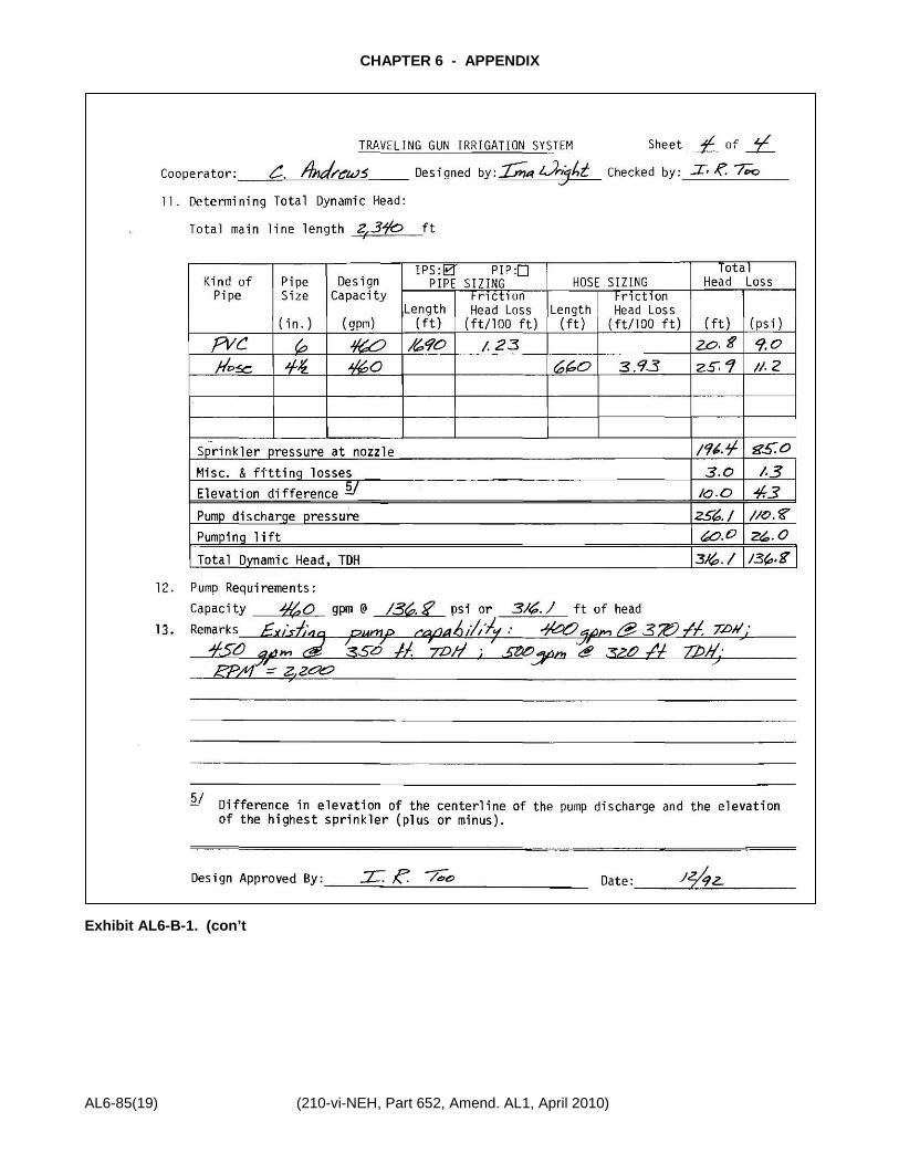
Step 9. Size the mainline and determine the total dynamic head (TDH) required for the pump:
a. Complete Item 11 for sizing the pipe. Use a 6-inch diameter: PVC, SDR 26 & IPS pipe. A length of 1,690 ft was determined from the layout. The friction head loss is 1.23 ft/100 ft and is taken from Appendix b. The total head loss for the 6-inch PVC is 1.23 ft/100 ft x 1,690 ft = 20.8 ft.
b. Using 660 ft of 4½ in. flexible hose the irrigator has on hand, the friction loss taken from Figure AL6-B-1 is 1.7 psi/100 ft or 3.93 ft/100 ft. Total head loss for the hose is 660 ft x 3.93 ft/100 ft = 25.9 ft. Table AL6-B-1 is a guide for flexible hose selection.

CHAPTER 6-B - TRAVELING GUN SPRINKLER IRRIGATION SYSTEM
(210-vi-NEH, Part 652, Amend. AL1, April 2010) AL6-85(14)
c. Enter the sprinkler pressure at the nozzle, miscellaneous losses and elevation differences between the well, and the nozzle when located on the high point in the field.
d. The sum of a, b, and c gives a pump discharge pressure required of 256.1 feet of head or 110.8 psi.
e. The TDH is the pumping lift plus the pump discharge pressure. 256.1 + 60 ft = 316.1 ft = 136.8 psi.
f. The pump requirement of 460 pgm at 316.1 feet of head is within the capability of the pump.
Step 10. Complete the plans. The specifications, location of the pipe, check valve, air vents, pressure relief valve, risers, thrust blocks, etc., should be shown on the plans. See Sheet 2 of 4 of Exhibit AL6-B-1.
LAYOUT CONSIDERATIONS
Items that must be considered are as follows:
a. Plant spacing and/or row direction so that travel lanes can be located properly.
b. Location of obstacles and safety hazards.
c. Whenever possible, place the risers a full hose length away from the edge of the field. This facilitates laying out the hose and reeling it back up.
d. Soil limitations such as surface texture may necessitate a part-circle volume gun so that the area is not irrigated in front of the gun as it moves, providing a dry footing.
e. Topography may dictate the lane direction to prevent misalignment of the traveler while in operation.
CONSTRUCTION REQUIREMENTS
The following is a list of construction items that should be checked to assure quality installation:
a. The depth of cover over the buried mainline must be adequate for protection from vehicular traffic and the farming operation.
b. Dimensions and location of the thrust blocks to prevent pipe joint separation.
c. Location and size of air vents and pressure relief valve.
d. Size and proper direction of installed check valve.
e. Riser material, size, number, and location.
f. Pipe requirement verifications such as SDR number pressure rating, ASTM designation, PVC material, pipe diameter, and if PIP or IPS size.
g. Verify pump, motor, well size. Check nozzle pressure.

CHAPTER 6-B - TRAVELING GUN SPRINKLER IRRIGATION SYSTEM
AL6-85(15) (210-vi-NEH, Part 652, Amend. AL1, April 2010)
Table AL6-B-1. Guide for Flexible Irrigation Hose Selection
FLOW RANGE (gpm)
HOSE DIAMETER (in.)
50 - 150 2.5
150 - 250 3.0
200 - 350 3.5
250 - 500 4.0
500 - 700 4.5
> 700 5.0
Figure AL6-B-1. Irrigation Hose Pressure Loss Per 100 feet.

CHAPTER 6-B - TRAVELING GUN SPRINKLER IRRIGATION SYSTEM
(210-vi-NEH, Part 652, Amend. AL1, April 2010) AL6-85(16)
Exhibit AL6-B-1. Irrigation Data Sheet - Traveling Gun Irrigation System.
U.S. Department of Agriculture Natural Resources Conservation Service

CHAPTER 6-B - TRAVELING GUN SPRINKLER IRRIGATION SYSTEM
AL6-85(17) (210-vi-NEH, Part 652, Amend. AL1, April 2010)
Exhibit AL6-B-1. (con’t)

CHAPTER 6-B - TRAVELING GUN SPRINKLER IRRIGATION SYSTEM
(210-vi-NEH, Part 652, Amend. AL1, April 2010) AL6-85(18)
Exhibit AL6-B-1. (con’t)
CHAPTER 6 - APPENDIX
AL6-85(19) (210-vi-NEH, Part 652, Amend. AL1, April 2010)
Exhibit AL6-B-1. (con’t