part 6: environmental controls gosford development …
TRANSCRIPT

•
•
•
•
•
•

PART 6: ENVIRONMENTAL CONTROLS Extract from Gosford Development Control Plan 2013
PART 6: ENVIRONMENTAL CONTROLS
6.1 Acid Sulfate Soils
6.1.1 What are Acid Sulfate Soils
Potential acid sulfate soils are waterlogged soils containing a layer that is rich in iron sulfides. The
layer of soil may be clay, loam, or sand and is usually dark grey or greenish grey and soft in texture.
These soils form naturally in organically rich waterlogged sediments, in which bacteria convert sulfate
from saline water and iron from the sediment into iron sulfides. The formation of iron sulfides has
been occurring for 10,000 years and is still occurring today.
When potentially acid sulfate soils are exposed to oxygen, due to excavation or lowering of the water
table, the pyrite is oxidised to form a sulfur mineral and sulfuric acid (actual acid sulfate soils).
The sulfuric acid produced by oxidation of iron sulfides affects soil and water and can severely
damage the environment. Both plant and aquatic life can be affected by this process. In the soil, this
mix can make soil so acidic and toxic that few plants can survive. Furthermore, in some situations,
brought about by a combination of weather and hydrology, fish and crustaceans are not able to avoid
the sulfuric acid leachate and massive kills over entire estuaries may result.
Sulfuric acid leachate can corrode engineering works and infrastructure such as culverts, bridges and
weirs. The precipitation of iron hydroxide/oxide flocs from acidic rich waters can cause the blocking of
drains, wells and the reduction of aquifer recharge.
Acid sulfate soils are generally found in:
• Coastal lowlands, embayment and estuarine floodplains;
• Areas where the level of land is below 5 metres Australian Height Datum;
• Bottom sediments of estuaries.
6.1.2 Land to which this Chapter Applies
This chapter applies to the land identified as Classes 1, 2, 3, 4, & 5 on the maps marked Acid Sulfate
Soils Maps held by Council and referred to in Clause 7.1 of the Gosford LEP 2014.
6.1.3 Purpose of the Chapter
To provide more detailed guidelines associated with acid sulfate soils to those provided in Clause 7.1
of the Gosford LEP 2014.
6.1.4 Aims and Objectives
The aims of this chapter are to:-
1. To ensure effective management of areas containing Acid Sulfate Soils.
2. To provide guidance to landowners, consultants and the general community on the procedures
involved in the management of areas containing Acid Sulfate Soils.
3. To ensure that activities located within an area of Acid Sulfate risk are identified.
4. To require a preliminary Acid Sulfate Soil Assessment be undertaken to clarify the extent of risk.
5. To require, where necessary, an Acid Sulfate Soil Management Plan to be prepared where the
nature of development poses potential Acid Sulfate Soil Risk.

PART 6: ENVIRONMENTAL CONTROLS Extract from Gosford Development Control Plan 2013
6.1.5 Development Application Procedure
Step 1 Check Clause 7.1 of the Gosford LEP 2014 and the Development Control Plan 2013 - Acid
Sulfate Soils maps. These maps introduce various classes of land and determine whether a
Development Application is necessary.
Step 2 If the Gosford LEP 2014 and the Development Control Plan 2013 - Acid Sulfate Soil Maps held
by Council identify that a Development Application is required, there are two options. Either:
1. A suitably qualified professional is required to carry out a preliminary soil assessment to
determine the extent of acid sulfate soil. Details are provided in Section 6.1.9 of this
chapter and the Office of Environmental Heritage (OEH) Guidelines.
2. Assume that the soils within the site of the proposal contain acid sulfate soil and by-pass
this step and carry out step 3.
Step 3 Engage a suitably qualified professional to prepare an Acid Sulfate Soil Management Plan for
all proposals which will disturb/expose acid sulfate soils or potential acid sulfate soils.
It should be noted if the applicant chooses Option (a) in Step 2, depending on the results of the
investigation, an Acid Sulfate Soils Management Plan may still be sought.
6.1.6 Assessment - Acid Sulfate Soil Planning Maps
This chapter of the Gosford DCP 2013 refers to Acid Sulfate Soil Planning Maps held by Council. In
conjunction with Clause 7.1 of the LEP and this chapter of the DCP development consent is required
for specific works in five principal land classes as outlined in the LEP.
The onus is on the landowner, contractor and proponent of any works to check which class their land
falls within and whether a Development Application is required under these or any other planning
provisions. Land not classified on the maps may still require development consent in accordance with
another provision of the LEP. Check with Council to determine whether a development application is
required prior to commencing works.
6.1.7 What types of Development require Council's consent?
The following activities, works, development and the like are subject to the need to obtain
development consent if the land falls within classes 1 to 5 inclusive and the relevant criteria are met:
• Agricultural related works
• Agriculture
• Flood mitigation works
• Foundations
• Works that may alter groundwater levels
• Construction or maintenance of existing drains
• Buildings and structures
• Construction of roads
• Aquaculture ponds
• Sand and gravel extraction
• Dewatering of dams, wetlands or quarries
• Landforming works
• Engineering works
• Construction of artificial waterbodies (including canals, dams and detention basins)
• Excavation Works

PART 6: ENVIRONMENTAL CONTROLS Extract from Gosford Development Control Plan 2013
6.1.8 Preliminary Soils Assessment
Where it is proposed to carry out any of the activities which are subject to the need to obtain
development consent the application must be lodged with either a Preliminary Soils Assessment or
Acid Sulfate Soil Management Plan.
A Preliminary Soils Assessment must be undertaken by a suitably qualified person and include the
matters outlined in the OEH Guidelines.
All applicants have the opportunity to assume that the soils within the site of their proposal contain
Acid Sulfate Soil and by-pass the need to undertake a preliminary soil assessment. However, this will
necessitate an Acid Sulfate Soil Management Plan to be undertaken in accordance with Section
6.1.9.
6.1.9 Soil Management Plan
All Development Applications for proposals which will disturb Acid Sulfate Soils must include a Acid
Sulfate Soil Management Plan prepared in accordance with the OEH Guidelines, as amended from
time to time.
6.1.10 Joint Applications
Where a development involves, or may impact upon a number of properties in the one locality, a joint
development application for the work and its ongoing maintenance is encouraged by Council. This will
include the preliminary soil assessment and/or management plan outlined in Sections 6.1.8 and 6.1.9.
Development where this should apply would include maintenance of a new and/or existing drain that
traverses more than one property or flood mitigation works which may impact upon a specific area.
6.1.11 Drainage Management Plans
Where a property contains a series of drains or works which would require development consent for
each individual section, the owner is encouraged to submit a drainage management plan for the
whole property. This plan would form part of the development application. Such a management plan
would cover all the drains on that specific property, including their maintenance and rehabilitation
details, as needed.
Council encourages this approach by landowners as it promotes better overall management of the
property and provides Council with a more complete overview of the location, ongoing maintenance
and interaction of such drains.
A property owner who has prepared a drainage management plan may also enter into a joint
application; however, the applicant should be aware that in the case of a joint development consent
any amendment to the drainage management plan would require the written support of each
landowner involved in the consent.
6.1.12 Determination by Council
In the case of a joint application or a drainage management plan Council will determine the
application in accordance with the provisions of this chapter. Where development consent is given, no
further development application will be required for those works provided any ongoing maintenance
and management is carried out in accordance with the terms and conditions of the consent. For
example: if an approved drain is to be deepened, widened, extended etc and the original consent did
not allow for that work, then development consent would be required. However, if the applicant
continued maintaining the drain in accordance with the consent, no further application would be
required.

PART 6: ENVIRONMENTAL CONTROLS Extract from Gosford Development Control Plan 2013
Any applicant working under a joint development consent or drainage management plan is
encouraged to contact Council's Governance and Planning Department if there are any questions as
to the terms and conditions of a consent.
New owners of property should also contact Council's Governance and Planning Department as
terms and conditions of a development consent issued by Council apply to the property. When a
property is bought or sold the consent stays with the property. The new owner must comply with the
consent or where an amendment is sought; have support, in writing, of all the joint applicants.
In deciding whether to grant consent to the application, Council shall take into consideration the
likelihood of the development resulting in the oxidation of acid sulfate soils and the adequacy of any
Management Plan.
1. .

PART 6: ENVIRONMENTAL CONTROLS Extract from Gosford Development Control Plan 2013
Pearl Beach
6.3 Erosion Sedimentation Control
6.3.1 Where this Chapter Applies
This chapter applies to any activity that involves, or could involve:
• disturbance of, or placing fill on, the soil surface, and/or changes to the contours of the land; or

PART 6: ENVIRONMENTAL CONTROLS Extract from Gosford Development Control Plan 2013
• changing the rate and/or volume of runoff flowing over land or directly/indirectly entering
receiving waters.
It covers the whole process of development and construction, from initial planning to final site
stabilisation.
6.3.2 Purpose of this Chapter
Council's goal is to help achieve a healthy, productive and diverse catchment. Erosion of soil as a
result of disturbance or mismanagement of land is inconsistent with this goal.
6.3.3 Objectives
The objectives of this chapter are:
• To prevent land from being degraded by soil erosion or unsatisfactory land and water
management practices.
• To protect streams and waterways from being degraded by erosion and sediment caused by
unsatisfactory land and water management practices.
• To promote and protect biodiversity.
6.3.4 Intent
Under this chapter, Council will implement and enforce a uniform set of regional soil conservation and
stormwater management standards. They will control planning and management of all forms of
private and public development or activities within the area.
It is proposed to improve land and water management by application of these principles:
• to conserve tree and vegetation cover on land through control of the location, timing, extent and
nature of clearing.
• to minimise erosion of soil through control of surface water flow paths and volumes across
disturbed sites.
• to intercept and contain erosion products on disturbed sites by requiring installation of sediment
traps or equivalent measures. This will avoid transfer of mobilised sediment and other pollutants
to adjoining land and watercourses.
• to ensure prompt and effective stabilisation of disturbed land through control of the location,
timing, extent and nature of rehabilitation and landscaping measures.
6.3.5 Erosion and Sediment Control Plans
6.3.5.1 Preamble
The Erosion and Sediment Control Plan (ESCP) and schedule of works implementation plays an
integral part in the planning and design stage of a development or project.
An ESCP is essential for any development with potential to cause soil erosion and sedimentation. The
greater the potential for these impacts the more detailed the plan. For example, a small development
may require a simple sketch with accompanying notes but a large complex development would need
a comprehensive plan, documentation and design/construction data.
An ESCP, developed to the Soils and Construction Managing Urban Stormwater Standards (Landcom
2004) standards, will be required to gain development consent or building approval. The ESCP must
be approved before commencement of site works.
Effective erosion and sediment control on a site can only be achieved by planning and implementing
measures as a part of the construction proposal.

PART 6: ENVIRONMENTAL CONTROLS Extract from Gosford Development Control Plan 2013
6.3.5.2 Aims of an Erosion and Sediment Control Plan
• To demonstrate that appropriate controls are planned
• To address all aspects of site disturbance, erosion, sediment control
• To address site rehabilitation for the duration of the project
• To provide a mechanism for any remaining exposed soil to be treated and for ongoing site
maintenance
• To cover the contingency of change or delay in the project implementation, activity or work
scope.
6.3.5.3 Erosion and Sediment Control Strategy
For major proposals that are staged over an extended period Erosion and Sediment Control
Strategies may be required in addition to staged Erosion and Sediment Control Plans and schedules
of works implementation. The fundamental issues are:
• Erosion control measures need to be applied within the site to minimise erosion.
• Acknowledge that some erosion will occur, and to take steps to intercept and retain sediment
within the work site.
6.3.5.4 Erosion and Sediment Control Plans
If required, the ESCP should be prepared by a suitably accredited or experienced practitioner. It can
be a "stand alone" document or incorporated into a site management or construction plan that shows
drawings and notes that site personnel can fully interpret. Such plans are not limited to erosion and
sediment control, but may also address other water quality and/or quantity issues during the
construction and operational stages of an activity.
"An ESCP is an evolutionary document and should not be compared to an engineering plan. The
latter shows a system of works which have fixed locations. In contrast, the ESCP is liable to show
conceptual locations of various systems (e.g. sediment fences, sediment traps, sediment basins)
which need to be formally located at the commencement of construction in line with commonsense
and best construction practice. Further refining of the plan will need to be done as the works progress
and in anticipation or response to prevailing weather conditions"....P Dwyer (1997)
6.3.5.5 Broad Structure of Erosion and Sediment Control Plans
The degree of detail supplied by the proponent to Council depends on:
• the scale of the activity
• the complexity of the site characteristics
• the sensitivity of the adjoining environment.
Where an Erosion and Sediment Control Plan is required it should be prepared in accordance with the
broad structure set out below. The ESCP must be submitted to Council with all necessary supporting
information to allow a critical review and approval.
1. Site Characteristics including:
• Locality plan (1:1000 Scale)
• Existing contours data
• Catchment area boundaries
• Principal geographic features
• Critical natural areas (eg., wetlands)
• Location and limitations of major soil types
• Location, nature and condition of existing trees and vegetation
• Soil subsidence
• Climatic data including rainfall and storm events.

PART 6: ENVIRONMENTAL CONTROLS Extract from Gosford Development Control Plan 2013
1. Clearing and Disturbance of Site including:
• Nature and extent of trees and vegetation to be cleared
• Scheduling and time of proposed disturbance
• Final site contours data
• Identify areas of cut and fill, location of soil stockpiles and spoil/tree and vegetation
dumping proposals.
2. Existing and Proposed Drainage Patterns including:
• Catchment boundaries
• Existing watercourses flowing through or adjacent to the site
• Location and extent of impervious surfaces
• Location and capacity of the proposed temporary and permanent site drainage or
stormwater system.
3. Erosion Control Practices including:
• Location, design criteria and construction details of temporary and permanent structural
and vegetative measures
• Scheduling details
• Monitoring and maintenance details.
4. Sediment Control Practices including:
• Location, construction details and design criteria of temporary and permanent structural
and vegetative measures
• Scheduling details
• Monitoring and maintenance details.
5. Rehabilitation Program including:
• Location of temporary and permanent revegetation sites
• Materials and species selection
• Application and planting methods
• Types and rates of fertilisers and other soil ameliorants
• Mulching details
• Scheduling details
• Monitoring and maintenance details.
6.3.5.6 Plan Variations
An ESCP needs to demonstrate that appropriate controls have been planned to minimise erosion and
soil movement both on and off the site. The plan needs to include specifications and or calculations
which illustrate that the control measure has design criteria and a completed capacity that exceeds
the calculated output anticipated from the catchment during the proposed project or stage.
Review and variation to the original ESCP may be required for each stage within an extensive or long
term project. However where site conditions necessitate plan modification, changes must be
endorsed by Council.
6.3.5.7 Further Information
Due to the range of developments undertaken and the varying characteristics of individual sites, the
location and combination of erosion and sediment control measures must be specifically designed for
each individual development. This chapter outlines the basic control methods to be used. Because of
the diversity of site problems, use or promotion of prescriptive or model ESCPs to suit all site
situations for the submission of Development Applications is not encouraged.
PART 6: ENVIRONMENTAL CONTROLS Extract from Gosford Development Control Plan 2013
It is also recommended that:
1. In complex situations the designer of the ESCP refers to the following:
• Urban Erosion and Sediment Control (DLWC, 1992)
• Soil and Water Management for Urban Development (D of H 1993)
• Urban Erosion and Sediment Control Field Guide, (DLWC 1992)
• Pollution Control Manual for Urban Stormwater, (SPCC 1989)
• Glossary of Terms Used in Soil Conservation (SCS 1986)
• Erosion and Sediment Control Standard Diagrams (DLWC 1997)
1. Expert advice on the preparation of ESCPs is available from Council.
6.3.6 Requirements
6.3.6.1 Coverage
1. This chapter relates to all private and public building works, developments, subdivisions and
activities subject to the assessment and consent of Council under the provisions of Parts 4 or 5
of the Environmental Planning and Assessment Act 1979 and/or under the Local Government
Act 1993 for any proposal or practices which will or could involve:
• the disturbance of or placement of fill on the soil surface, and/or result in change to the
contours of land
• change in the rate and/or volume of runoff flowing over land or directly or indirectly
entering in "waters".
2. To satisfy the requirements of the chapter on erosion and sediment control a proponent shall
either:
• prepare and implement an Erosion and Sediment Control Plan; or
• implement erosion and sediment control measures specified in (or attached to) the
development application or activity specification.
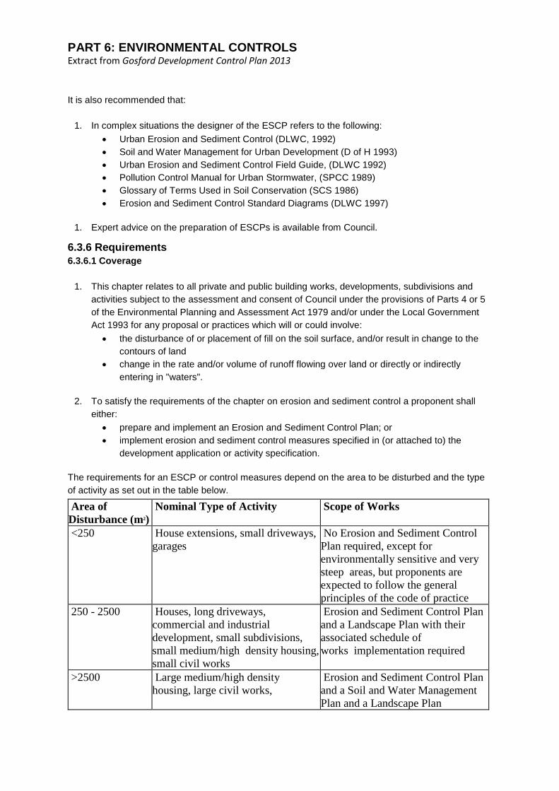
The requirements for an ESCP or control measures depend on the area to be disturbed and the type
of activity as set out in the table below.
Area of
Disturbance (m2)
Nominal Type of Activity Scope of Works
<250 House extensions, small driveways,
garages
No Erosion and Sediment Control
Plan required, except for
environmentally sensitive and very
steep areas, but proponents are
expected to follow the general
principles of the code of practice
250 - 2500 Houses, long driveways,
commercial and industrial
development, small subdivisions,
small medium/high density housing,
small civil works
Erosion and Sediment Control Plan
and a Landscape Plan with their
associated schedule of
works implementation required
>2500 Large medium/high density
housing, large civil works,
Erosion and Sediment Control Plan
and a Soil and Water Management
Plan and a Landscape Plan
PART 6: ENVIRONMENTAL CONTROLS Extract from Gosford Development Control Plan 2013
commercial and industrial
development, large subdivisions
with their associated schedule of
works implementation required
Source after Landcom 2004 Soils and Construction - Managing Urban Stormwater
6.3.6.2 Compliance Responsibility
The proponent is responsible for the full cost of all work required complying with this chapter, as
determined by Council. Off site damage resulting from the activity is also the responsibility of the
proponent.
All erosion and sediment control measures or works and rehabilitation measures must conform to or
exceed the specifications or standards set out in Soils and Construction - Managing Urban
Stormwater, Landcom (2004).
Works must be executed so as to disturb as little of the site as possible, and stabilise the site as
quickly as possible. A staged Erosion and Sediment Control Plan and/or strategy is required for
proposals scheduled to be undertaken over more than one year.
An approved Erosion and Sediment Control Plan with associated schedule of works for
implementation shall demonstrate:
• that selected measures have a design life that exceeds the project or stage,
• a capacity to manage the anticipated output from the catchment.
If the site disturbance is greater than 2500m2, the proponent will have all construction and
maintenance associated with erosion and sediment control measures regularly inspected and
supervised by personnel who have appropriate training and/or demonstrated knowledge in erosion
and sediment control.
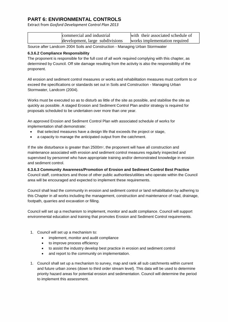
6.3.6.3 Community Awareness/Promotion of Erosion and Sediment Control Best Practice
Council staff, contractors and those of other public authorities/utilities who operate within the Council
area will be encouraged and expected to implement these requirements.
Council shall lead the community in erosion and sediment control or land rehabilitation by adhering to
this Chapter in all works including the management, construction and maintenance of road, drainage,
footpath, quarries and excavation or filling.
Council will set up a mechanism to implement, monitor and audit compliance. Council will support
environmental education and training that promotes Erosion and Sediment Control requirements.
1. Council will set up a mechanism to:
• implement, monitor and audit compliance
• to improve process efficiency
• to assist the industry develop best practice in erosion and sediment control
• and report to the community on implementation.
1. Council shall set up a mechanism to survey, map and rank all sub catchments within current
and future urban zones (down to third order stream level). This data will be used to determine
priority hazard areas for potential erosion and sedimentation. Council will determine the period
to implement this assessment.

PART 6: ENVIRONMENTAL CONTROLS Extract from Gosford Development Control Plan 2013
6.3.6.4 Variations to Requirements
Council can vary approval requirements under this chapter in the following circumstances:
• On allotments sized less than 450 square metres. In these circumstances an on-site
determination of suitable erosion and sediment control measures or negotiated contribution to
other catchment works by the proponent will be made. This is required before formal plan
submission where the small size of the allotment makes on-site control impractical.
• On very large allotments (greater than 5000 square metres) and/or rural situations. Here only
minimum erosion and sediment control measures might be required, provided the proposed
activity is surrounded by an appropriately wide vegetative filter strip and the intent of clause
6.3.6.5 is satisfied.
6.3.6.5 Planning and Designing Works
An Erosion and Sediment Control Plan shall be approved by Council. This plan will contain a
schedule of works implementation that addresses all aspects of site or tree and vegetation
disturbance, runoff, flow rate change, erosion and sediment control and site rehabilitation for the
duration of the project. Council will review the plan annually. However it will be modified by the
proponent as required, to achieve erosion and sediment control throughout the life of the development
or activity. (Refer to Section for detail on Erosion and Sediment Control Plans).
Submitted plans should follow the general principles of Total Catchment Management and
Ecologically Sustainable Development as applied by Council's development policy for the specific
catchment area.
Council Policy requires an Erosion and Sediment Control Plan and associated schedule of works
implementation where required, to be technically assessed by an accredited person or organisation
before approval is granted. The Plan and/or schedule may be approved before or with all domestic,
commercial and industrial building works, development, subdivision or activity proposals.
Earthworks (including site clearing for the erection of a structure for which development consent is not
required) must not commence before any construction certificate or other approval is issued. The
extent of disturbance shall be shown on the ESCP. The disturbed ground must not reach further than
3 metres from the outermost projection of the approved building or structure or land required for
permanent access or car park.
Approved runoff and erosion control works must be installed before any work on the approved
development begins.
Councils and Public Authorities Categories
1. Erosion and Sediment Control Principles
Principles of erosion and sediment control applied in all planning and design activity shall
comply with the Regional Policy and Code of Practice Erosion and Sediment Control. Where
appropriate they will incorporate the following:
1. Erosion and sediment control measures, where required, will be integral components of all
job design and costing
2. No work shall be carried out on public or private land unless accompanied by measures
which minimise soil erosion and prevent sediment escaping from the site at levels greater
than those allowed by the EPA.

PART 6: ENVIRONMENTAL CONTROLS Extract from Gosford Development Control Plan 2013
3. Trees and vegetation shall not be removed before approval to commence works on any
stage of the development. The only exceptions are for survey purposes or other activity
allowable under Cl 5.9 of Gosford LEP 2014 and the Preservation of Trees or Vegetation
chapter of this DCP.
4. Disturbance to trees and vegetation and land at a works site will be minimised. Clearing
and earthworks extent and timing shall be matched to development stage and conform to
an approved schedule of works.
5. Trees and vegetation removed at an approved activity site shall be reused on site either as
a log or chip form, with saleable product salvaged and debris disposed of at an approved
landfill site.
6. Any native trees, vegetation or tree of significance that is outside the approved works area
but within the development site boundary must be identified on the approved plan and
protected by barrier fencing or a strategy that achieves the same end.
7. Run on water from land surrounding the activity site shall be intercepted and diverted to a
stable waterway or disposal area, where appropriate and legal.
8. Erosion control practices are to be implemented across the site. Sediment trapping
measures are to be located at least at all points where site stormwater can enter
constructed stormwater inlet pipes or leave the activity or development site.
9. Topsoil shall be stockpiled in mounds less than 1 metre high (where revegetation by the
contained seed source is proposed) and protected with sediment control measures. It will
generally be respread to a depth of 100 mm on all exposed areas, after final land shaping.
Stockpiles will not be located on a nature strip, footpath, roadway, kerb, access or within a
drainage line without Council permission.
10. Stockpiled material that is scheduled to remain undisturbed for more than one month will
be surface stabilised within 14 days of placement or within an approved period. Surplus
topsoil can be removed from site. Excess subsoil or spoil may be retained onsite in
approved areas, top soiled and stabilised or removed from the site.
11. Access to and within the construction site shall be controlled, where practical, vehicle and
plant entry/exit to the site will be restricted to a single, well defined all weather access.
Vehicular operation within the construction site must be limited to approved areas by
placement of operational boundary markers.
12. Trenches shall be backfilled, compacted, capped with topsoil and surfed or sown with
approved seed within 24 hours of inspection. The proponent is encouraged to arrange the
common placement of utilities for minimum open trench time.
13. All disturbed areas shall be progressively stabilised so that no area remains an erosion
hazard for more than 14 days (or another approved period) after earthworks cease.
2. Reserves
Council shall prepare and implement an approved management plan on public reserves it
administers. The plans will incorporate erosion and sediment control measures and proposals
for undertaking clearing for the purpose of bushfire protection, removal of noxious weeds or
known vermin harbour.
Building Construction Category
1. All building applications, where the project involves site disturbance, excavation or filling must
be accompanied by details of the proposed method of erosion and sediment control on the
building site. Industrial and commercial building allotments require the submission of a more
detailed Erosion and Sediment Control Plan with associated schedule of works implementation.

PART 6: ENVIRONMENTAL CONTROLS Extract from Gosford Development Control Plan 2013
2. The consent authority may require an Erosion and Sediment Control Plan with associated
schedule of works implementation and/or compliance with this chapter during erection of a
building for which development consent is not required.
6.3.6.6 Training
Council shall assist in disseminating information to industry/staff and the wider community on erosion
and sediment control.
Council and Authority employees will be adequately trained to allow adoption of workplace practices
that minimise erosion and prevent sediment from the activity sites entering adjoining land and
"waters".
The proponent will train employees adequately to allow adoption of workplace practices that minimise
erosion and prevent sediment from activity sites entering adjoining land and "waters". The proponent
should encourage site sub-contractors to be aware of and implement the requirements for Erosion
and Sediment Control enforced within the Local Government Area.
6.3.6.7 Tree and Vegetation Management
1. Approved management or removal of site tree/vegetation shall comply with:
• The principles of erosion and sediment control stated within Clause 6.3.6.5 (Planning and
Designing of Works)
• Clause 5.9 of Gosford LEP 2014
• The Preservation of Trees or Vegetation chapter of this DCP
• Relevant State Government legislation or regulation.
1. The Erosion and Sediment Control Plan will incorporate a schedule of works that illustrates the
on-site tree/vegetation management to be undertaken by the proponent.
Councils, Public Authorities and Land Subdivision Categories
1. There shall be no soil disturbance or exposure, including the removal of tree or vegetation,
before the approval of an Erosion and Sediment Control Plan unless exempt under Gosford LEP
2014 and the Preservation of Trees or Vegetation chapter of this DCP. In some villages and
rural areas clearing of native tree/vegetation will be subject to State regulation as well as the
local LEP.
2. Offences against the provisions of the Gosford Local Environmental Plan 2014 that involve the
unauthorised injury, removal or destruction of trees or clearing of vegetation, can be prosecuted
under the provisions of the Environmental Planning and Assessment Act 1979.
3. Approved engineering plans for a land subdivision shall allow a 5 metre maximum vegetation
clearing distance from the edge of any essential construction activity, but a 3 metre operating
distance is preferred by Council. Where other legal requirements occur the set back distance
may be different from that stated in this Code.
4. Multi-staged subdivisions shall only have sufficient area approved at each stage to allow
progressive development to be undertaken.
5. Approval of land clearing undertaken on private or public lands for an activity or development
will be subject to the installation of adequate runoff, erosion and sediment control measures.
6. Any nominated trees cleared will be replaced according to conditions contained in Clause 5.9 of
Gosford LEP 2014 and the Preservation of Trees or Vegetation chapter of this DCP.

PART 6: ENVIRONMENTAL CONTROLS Extract from Gosford Development Control Plan 2013
6.3.6.8 Soil Erosion and Sediment Control
While carrying out any approved work covered by this chapter, the proponent must minimise erosion
on-site and retain sediment eroded by water or wind on the development site. This will involve as
many of the principles and practices listed below as required to meet this objective:
1. Installation and maintenance of the erosion and sediment controls set out in the approved
Erosion and Sediment Control Plan, and the associated tree/vegetation clearing and works
implementation schedule.
2. Use of water runoff detention and sediment interception measures, where required. These will
reduce flow velocities and prevent disturbed material (including topsoil, sand, aggregate, road
base, spoil or other sediment) escaping the site or entering any adjacent lands or receiving
waters.
3. For a proposal with a disturbed area greater than 5 hectares, the proponent must demonstrate
that runoff frequency or peak downstream of the development will not be increased.
4. Sediment detention basins will be installed if total sediment volume calculated for the proposal
catchment exceeds 150 cubic metres in the design Annual Recurrence Interval (ARI) 5 year
storm event. These basins must be maintained until consent conditions are fulfilled.
5. Where the subsoils within the development site contain more than 10% dispersible soils
material, the proponent will capture and treat all runoff to a level specified by the EPA before
discharge to receiving waters.
6. Wind erosion mitigating practices and associated sediment interception structures must be
applied to the land to reduce wind erosion where required.
7. Appropriate water and wind erosion control measures will be in place before land is disturbed
and maintained until effective land stabilisation is completed.
8. The proponent must control vehicular access to prevent sediment being tracked onto adjoining
land and roads. Aggregate and any construction site sediment on sealed roads will be
thoroughly swept and removed to prevent this material entering the drainage system. Runoff
from access surfaces must drain into an approved sediment trap device, and be treated where
required, before release from the development site.
Councils, Public Authorities and Land Subdivision Categories
1. A sediment fence and/or similar trapping measure will be installed within the property boundary
and downslope of any cleared and/or disturbed area, to prevent sediment and other debris
leaving the site.
2. Erosion and sediment control practices are to be implemented across the site, while sediment
trapping measures are to be located at all points where stormwater can enter constructed
stormwater inlet pipes or leave the activity site. Design values for erosion, sediment control and
stormwater works will be at an Annual Recurrence Interval (ARI) as set out in the following
table.
6.3.6.9 Runoff Water Control
During the implementation of any approved work covered by this chapter, the proponent must retain
sediment eroded by water on the development site. This can be achieved by carrying out as many of
the following principles and practices as are required to meet this objective:
1. Intercept and divert all uncontaminated runoff around all areas to be disturbed. Alternatively
runoff can be directed through these areas in a controlled manner.
2. Where Council decides water quality control works are necessary, it can accept them into open
space calculations. Council may also accept non-structural measures for addressing water

PART 6: ENVIRONMENTAL CONTROLS Extract from Gosford Development Control Plan 2013
quality, such as a Section 94 contribution to stream bank protection/stabilisation or even
community educational measures.
3. Connect all roof drainage to Council's stormwater management system immediately after the
installation of roof material. Where this stormwater management system is not available,
downpipes must discharge away from the building site onto a stable area within the property
boundary. Install measures to control runoff from the downpipe discharge area to manage
erosion and sedimentation.
4. Control all runoff from the proposed development likely to cause flooding or erosion of
downstream watercourses with appropriate drainage, channel or detention works. These works
can be located above, within or below the approved development site.
5. Ensure all drainage conduits and related structures are completed before they are
commissioned. This includes all energy dissipaters and sediment
6.3.6.10 Construction Site Management
1. There shall be minimal site disturbance. Site excavation will be designed and located to
minimise cut and fill requirements. Measures to provide flow dissipation and scour protection
within channels and at all pipe outlets must be installed.
2. No tree or vegetation shall be removed before Council approval to commence works on any
stage of the development.
Councils, Public Authorities and Land Subdivision Categories
1. Roads and Access Tracks
1. Priority for road shoulder stabilisation shall be determined by Council on the basis of a
completed erosion hazard survey. Ranking will be reviewed annually.
2. Road shoulders and table drains beside sealed roads:
• Where slope gradients of table drains are generally less than 5% and
construction of kerb and guttering is impracticable, drainage will be by
progressive installation of grassed table drains shaped to facilitate maintenance
mowing. Road shoulders and table drains shall be compacted, ideally topsoiled,
and grassed during reshaping so as to direct the surface runoff, without erosion,
into the drainage system.
• If slope gradients of table drains are generally greater than 5% and construction
of kerb and guttering is impracticable, road shoulders and table drains will be
drained by progressive implementation of appropriate erosion control measures
and vegetated where possible.
1. Maintenance mowing of road shoulders, table drains, batters and other surfaces must
leave a stable vegetative cover no shorter than 75mm.
2. Routine grading beside sealed road shoulders shall be limited to essential pavement
edge maintenance. Where appropriate, program of grassed road edge maintenance
mowing, or the application of equivalent stabilising measures shall be implemented.
3. Maintenance of unsealed roads and shoulders shall be carried out so as to include
sediment trapping sumps/devices within the length of the table drain or in association
with minor culvert structures.
4. Where possible, a single access (3 to 5 metres width per lane) shall be provided to and
within the construction site. After formation, the entry/exit surfaces shall be covered as
needed by a layer of geotextile and 200 mm deep aggregate of greater than 40mm
diameter or other approved materials. This will protect temporary access from surface
erosion during building activity.

PART 6: ENVIRONMENTAL CONTROLS Extract from Gosford Development Control Plan 2013
1. Cut and Fill Batter Management
1. Road construction, or access track and infrastructure construction shall disturb the
minimum amount of land needed to implement the activity.
2. A diversion and/or catch drain shall be installed to direct the water to a stable outlet if the
catchment area above any batter exceeds 2000 square metres, or the slope gradient
exceeds 20% and the flow of runoff is sufficient to scour batters.
3. Fill batters must be sited to avoid encasing established trees where possible.
4. All cut or filled batters shall be effectively stabilised or revegetated as soon as possible
after formation.
1. Drainage
1. Where proposed activities are predicted to increase stormwater runoff volume and rate, the
proponent will provide appropriate drainage. This will include energy dissipation and/or
detention measures to prevent channel erosion and minimise adverse ecological impacts
or flooding within the site or the catchment.
2. The ARI I in 5 year storm event must be used as the minimum design criteria for minor
drainage conduits for all urban runoff works. Flooding hazard zones shall exist where the
stream has a calculated annual excedence probability (AEP) greater than 1%.
3. Run on water from land surrounding the activity site is to be intercepted and guided from
the area to be disturbed to a stable waterway or disposal area, where appropriate and
legal.
4. Erosion and sediment control practices are to be implemented across the site, while
sediment trapping measures are to be located at least at all points where stormwater can
enter constructed stormwater inlet pipes or leave the activity or development site.
2. Drain Maintenance
1. Channel maintenance shall be carried out, as required, to restore water carrying capacity.
Clearing of excess trees and vegetation to maintain channel capacity shall, where possible
use selective trimming to leave a short, dense, living ground cover that will continue to
stabilise the channel banks/bed and provide a sediment or nutrient trapping measure.
2. Council's preferred option during drainage system upgrades or restoration is to establish
the channel as a grassed open drain instead of closed pipe or concrete lined channel if
possible.
3. Where easement width and soil conditions permit, Council shall at least follow the
construction and maintenance guidelines contained in the NSW Department of Planning's
publication "Better Drainage" (1993).
4. Removal of dead trees from channel banks shall be by cutting the trunk close to the ground
and leaving the root mass undisturbed.
5. Excess or undesirable trees/vegetation in drainage lines will be poisoned only if other
methods of control are impractical and after obtaining appropriate permits.
3. Dredging
Dredging or excavation of a major channel to maintain water carrying capacity will be carried out
after approval under appropriate legislation. The work shall be carried out with due regard for
problems associated with contaminated sediment and / or possible acid sulphate soil material
and without unnecessary damage to stabilising riparian trees and vegetation.
4. Quarries
Quarries shall be operated and maintained so as to prevent sediment moving off site onto
adjoining land or "water". Existing quarries must be progressively rehabilitated to minimise future
soil erosion hazard.

PART 6: ENVIRONMENTAL CONTROLS Extract from Gosford Development Control Plan 2013
Building Construction Category
1. Roads and Access Tracks
1. Access track and infrastructure construction shall disturb the minimum amount of land
necessary.
2. Where possible, a single access (3 to 5 metres width per lane) shall be provided to and
within the construction site. After formation, the entry/exit surfaces shall be covered as
needed by a layer of geotextile and 200 mm deep aggregate of greater than 40mm
diameter or other approved materials to provide temporary access protection from surface
erosion during building activity.
3. Aggregate and accumulated or deposited construction site sediment on sealed roads must
be thoroughly swept and removed to prevent this material entering the drainage system.
2. Turf Filter Strips
1. A turf filter strip shall be installed and maintained along the road nature strip/footpath area
adjacent to street kerbs (or along the downslope boundary). It is to act as a final filter for
the runoff leaving the property. Any exposed soil on the footpath and allotment shall be
seeded or otherwise revegetated to limit runoff water and sediment.
2. In areas where the property is adjacent to bushland, care is needed to prevent the spread
of turf grasses or hydro-mulch material beyond the rehabilitated area. Use of tree mulch or
sterile seed/grass stock or native seed/seedling may be preferable to pasture species or
couch turf in such locations.
3. Sediment Control
1. A sediment fence shall be installed to provide a temporary barrier or filter geotextile
structure that captures sediment from sheet flow runoff. It will be located within and/or
along the downslope boundary of any construction site or upstream of a turf filter strip or
native trees/vegetation. Generally sediment fencing is restricted to small catchment areas
with a slope length of less than 60 metres, and away from concentrated flow paths.
2. Sediment traps will be installed to provide a temporary sediment control measure to
intercept and retain sediment laden runoff in an excavation and/or an embankment located
at all points where stormwater can leave a construction site or enter a drainage system. On
sites with highly dispersible or erodible soil Council requires runoff within sediment traps to
be filtered or flocculated before the water is released to the environment.
4. Roof Water Disposal
1. All roof guttering and downpipes shall be installed and connected to Council's drainage
system or other approved drainage system immediately after roof material fixing. if this
connection cannot be made immediately, then on site sediment control devices must be
installed to receive and mitigate roof water runoff
2. Where no Council drainage system is provided, the roof stormwater shall be discharged
away from the building site onto a stable vegetated area within the property with sediment
control devices installed.
6.3.6.11 Services and Utilities Management
Site disturbance for the installation of services and utilities will be minimised. Site excavation shall be
designed and located so as to keep cut and fill requirements to a minimum.
1. The proponent is encouraged to use common placement of utilities with minimum trench open
time.
2. If a trench requires drainage by pumping out during construction, the water must be contained
for filtration or flocculation, prior to release to receiving waters.

PART 6: ENVIRONMENTAL CONTROLS Extract from Gosford Development Control Plan 2013
Trenches shall be backfilled, compacted, capped with topsoil and surfed or sown with approved seed
within 24 hours of service installation.
6.3.6.12 Rehabilitation
The proponent will carry out progressive land surface stabilisation on all disturbed areas until the site
is satisfactorily rehabilitated, and where appropriate, landscaped to the satisfaction of Council.
1. All disturbed areas shall be progressively stabilised and/or revegetated across the site. No
completed area is to remain exposed to erosion for more than 14 days or another approved
period. Installed temporary sedimentation control measures are to be maintained until the area
stabilisation is complete and then decommissioned.
2. If the sowing of seed is used as a primary rehabilitation measure on disturbed ground, additional
erosion and sediment control measures must be carried out. These can include turf stripping or
sediment fences. They will be maintained until an effective 70% vegetative ground cover has
established over the completed area.
3. The removal or management of trees/vegetation within Council area shall be consistent with the
Gosford LEP 2014 and the Preservation of Trees or Vegetation chapter of this DCP.
6.3.6.13 Topsoil and Stockpile Management
1. Topsoil will only be stripped from approved areas to a predetermined depth.
It must be stockpiled separately from subsoil for re use during site rehabilitation and
landscaping, or removal if there is an excess. Subsoil spoil not required may be removed or
placed on site, in approved areas, shaped to appropriate land contours, topsoiled and stabilised
by the proponent.
2. Stockpiles of topsoil, sand, aggregate, spoil or other material shall be stored at least 2 metres
clear of any drainage line or easement, natural watercourse, footpath, kerb, road surface or
established tree. Stockpiles must have measures in place to retain such materials on the
stockpile
3. Topsoil shall be stockpiled in mounds less than 1 metre high (where revegetation by the
contained seed source is proposed). It will be protected with sediment control measures and
respread on all exposed areas to a depth of at least 100 mm on slopes flatter than I :4. The
minimum depth will be 50 mm on slopes up to 1:2, after final land shaping.
4. Stockpiled material that is scheduled to remain undisturbed for more than one month shall be
surface stabilised within 14 days of placement or within an approved period.
5. Stockpiles of erodible building materials or soils will not be located on a nature strip, footpath,
roadway, kerb, access, or Public Reserve and within 2 metres of a watercourse, without Council
approval.
6. The land adjoining the stockpile shall be protected from degradation by the implementation of
erosion and sediment control measures such as a diversion drain, sediment fence, geotextile or
other approved devices.
6.3.6.14 Erosion and Sediment Control Maintenance
All erosion and sediment control measures must be maintained at workable capacity or condition until
permanent rehabilitation measures are fully operational.
1. All erosion and sediment control measures, including permanent sediment traps, shall be
maintained as per the schedule of works within the approved Erosion and Sediment Control
Plan (or as required). At least 70% of their design capacity is to be operational until they are
decommissioned.

PART 6: ENVIRONMENTAL CONTROLS Extract from Gosford Development Control Plan 2013
2. Decommissioning of erosion and sediment control measures must comply with the schedule of
works within the approved Erosion and Sediment Control Plan. Material held in sediment control
measures on decommissioning shall be either stabilised in situ or removed to an approved
disposal site. AII structural materials used to construct temporary erosion and sediment control
measures are to be dismantled and removed from the site on decommissioning.
3. All site debris and unused construction material must be removed from the site or protected
from erosion before the site is vacated.
6.3.15 Environmental Performance Bond
Council may require the proponent to lodge a bond. This is to ensure effective erosion and sediment
control measures and rehabilitation works are implemented and maintained. The bond can be
required for any activity deemed by Council including the following situations:
• Proposals adjacent to environmentally sensitive areas
• Proposals with a disturbed area greater than 5 hectares
• Proposals involving exposure/disturbance of the land surface within the bed and banks of a
watercourse
• Proposals involving exposure/disturbance of the land surface for periods greater than 6 months
Before works are implemented Council may require the payment of a security bond by administrative
divisions or proponents to ensure effective erosion and sediment control measures and rehabilitation.
Activities associated with adjoining sensitive environments, extractive industry or substantial
development may attract this environmental performance bond charge.
1. The bond will be a suggested minimum of $3,000 per hectare of disturbed land, at a 30 June
2008 dollar value. It will change in line with Consumer Price Index at 1st July each year.
2. When the project is complete the bond will be released in full if all the development consent
conditions have been implemented and maintained and site rehabilitation is complete.
3. Council has the right to undertake any erosion and sediment control work, on or off site, deemed
necessary for the benefit of the community, without notice to the proponent. The cost of this
work may be recovered from the lodged security bond or by further legal action.
6.3.6.16 Legislative Responsibilities
The proponent is responsible for satisfaction of all legislative requirements associated with the activity
approval. Council will consider necessary action to be taken under relevant legislation if approved
erosion and sediment control measures are not carried out. Options include: the charging of a
reinspection the forfeit or partial loss of an environmental bond, the issuing of stop work notices or
other legal action
6.3.6.17 Restoration of Damage
If the proponent or their agents cause damage to any structure or surface that is the responsibility of
Council while carrying out works to comply with this chapter, repairs will be at the proponent's cost.
6.3.6.18 Exempt Works
The following situations are exempt from this Code of Practice:
1. Emergency Situations - This policy does not apply to land uses and/or activities such as
emergency flood mitigation or to emergency bushfire backburn operations. It also does not
apply to other such specific land uses more appropriately addressed by separate policies.
However, after the emergency situation has passed, remedial measures should be undertaken
to address any erosion hazard and to rehabilitate the site in a manner consistent with the Code
of Practice Erosion and Sediment Control;
2. Bushfire Management - Trails and tracks for bush fire prevention and control can be constructed
and maintained provided they comply with the appropriate Council Bush Fire Prevention and

PART 6: ENVIRONMENTAL CONTROLS Extract from Gosford Development Control Plan 2013
Control Policy and the relevant NSW Government Guidelines for Fire Trail Construction and
Maintenance, or a Plan prepared in accordance with section 41 A of the Bush Fires Act(1949);
and
3. Clause 5.9 of Gosford LEP 2014 - Removal or management of trees/vegetation within the site
must be consistent with Clause 5.9 of Gosford LEP 2014 and the Preservation of Trees or
Vegetation chapter of this DCP. This may contain conditions that override clauses this chapter.
For example, the proponent needs no additional approval to disturb the activity site for final
rehabilitation, except on land outside their administration, such as footpath or nature strip, etc.
Appendix A - Legal Requirements
Failure to comply with the requirements of this Chapter may result in action being taken by Council, or
another responsible authority, under relevant legislation. Proponents need to be aware of the
extensive amount of legislation relating to the protection of soil, water, habitat and land resources of
the NSW environment.
Farrier, D. (1993) "The Environmental Law Handbook Planning and Land Use in NSW" (2nd Edition),
provides a useful account of the relevant legislation which can be summaried as follow
1. Environmental Planning and Assessment Act 1979 The State's planning and development
processes are primarily controlled by this Act. It requires the preparation of Environmental
Planning Instruments (Part III), such as Local Environment Plans (LEPs) and the undertaking of
environmental impact assessments in the form of ElSs or SEEs (under Parts IV or V). The
potential for soil erosion and other landscape impacts have to be considered by the consent
authority when making approval decisions (Section 90(1) g & ml)
administered by the Department of Planning and Infrastructure (DOP&I).
2. Sch 3 to the Protection of the Environment Operations Act 1997 No 156provides for the
imposition of penalties for serious pollution offences in three tiers, up to $1 million. Administered
by the Environment Protection Authority (EPA).
3. Sch 3 to the Protection of the Environment Operations Act 1997 No 156forbids all activities
which result in water pollution, except where they are carried out in accordance with a licence
issued under Section 16. Such pollution includes soil sediments. Administered by the Office of
Environment and Heritage (OEH).
4. Soil Conservation Act 1938 provides for the conservation of soil resources and for the
mitigation of erosion. It allows prosecution of developers and landholders where action or failure
to act caused soil erosion or land degradation (Secdon.15A,18 or 22). The Protected Lands
provisions (Section 21 C) require the issuing of an authority under the Act prior to disturbance of
trees/vegetation within steeply sloping terrain, in riparian lands or in otherwise sensitive lands.
5. Local Government Act 1993 places responsibility with local Councils to properly protect,
restore, enhance and conserve the environment, which has an indirect bearing on the
development approval and Council operations. Administered by the Department of Planning and
Infrastructure (DoP&I).
6. Catchment Management Act2003 objective is to bring about the co-ordinated and sustainable
use and management of land, water, trees, vegetation and other natural resources on a
catchment basis. It relies on voluntary Cupertino of the community and government, rather than
a regulatory approach.
7. Sch 7 to the Water Management Act 2000 No 92provides for the protection and improvement of
protected waters (i.e., most rivers, lakes, In lagoons and estuaries) and the associated protected
lands, (i.e., beds, banks, shores and land within 40 metres these waters. A permit is required
under this Act for any activity that may interfere with the flow of these protected waters or for
any excavation or removal of material from protected lands.

PART 6: ENVIRONMENTAL CONTROLS Extract from Gosford Development Control Plan 2013
8. Sch 8 (a) to the Crown Land Management Act 2016 No 58 any activities occurring on Crown
Lands or lands adjoining, have to be authorised under this Act, generally through a licence,
lease or reserve. Activities must be in accordance with the Principles of Crown Land
Management which stress the protection of soil, water and other environmental values (Section
11).
9. sec 35 of the Coastal Management Act 2016 No 20 provides for the protection, maintenance
and restoration of the environment of the coastal region. Consent or concurrence under this Act
is required where there is no existing environmental planning instrument or where a significant
engineering or mining project is involved. It applies over the coastal zone which generally
includes the beach front, estuaries and adjoining wetlands, and offshore areas to 3 nautical
miles.
10. Other Legislation various other legislation relating to specific land uses provides for the
protection of soil and landscape resources including the Mining Act 1992, Sch 5 to the Forestry Act 2012, Pesticides Act1999, Environmentally Hazardous Chemicals Act 1985 and the Waste
Disposal Act 1970; Biodiversity Conservation Act 2016; National Parks and Wildlife Act 1974;
Land Services Act 2013; Roads Act Regulation 1993; and Fisheries Management Act 1994.
11. Relevant Government Policies A number of NSW Government policies also provide for the
protection of soil and landscape resources and influence the decision making process of NSW
Government agencies. Important relevant policies and regulations include:
• State Environmental Planning Policy (Coastal Management) 2018SEPP No.19 Bushland
in Urban Areas
• PPP New 9A 1 Littoral Rainforest
• Total Catchment Management (TCM) Policy
• NSW State Rivers and Estuaries Policy
• NSW State Wetlands Policy
• NSW State Coastal Policy
• NSW State Soils Policy
• NSW State Tree Policy
Penalties For Non Compliance
The is the most likely legislation to be breached regarding sedimentation off site by a proponent from
an approved development / activity site. Breaches of this Act incur penalties under the through a three
tier charge system. The fines may be imposed by Courts after action is taken by the Office of
Environment and Heritage (OEH) or a "third party". Council has powers to act by delegated authority
of the OEH to impose Tier 3 "on the spot" infringement penalties.
In order to improve the community awareness of this penalty system, the following outline is provided
as at July, 1997 and is subject to future revision by the State Government.
1. Tier I Offences are the most serious offences and typically involve deliberate or negligent
actions which result in significant harm to the environment. Such offences can result in fines for
corporations up to $1,000,000 or for individuals up to $250,000 and/or 7 years' imprisonment.
2. Tier 2 Offences typically involve serious or significant offences under the Clean Air or Clean
Waters Acts. These offences can result in fines for corporations up to $125,000 plus $60,000
each day the offence continues and for individuals up to $60,000 plus $30,000 each day the
offence continues.
3. Tier 3 Offences are those of a more minor nature which incur a maximum on the spot fine of
$600 and order to rectify the problem.
6.4 Geotechnical Requirements For Development Applications

PART 6: ENVIRONMENTAL CONTROLS Extract from Gosford Development Control Plan 2013
6.4.1 Where this Chapter Applies
This chapter applies to all Land in Gosford LGA.
6.4.2 Purpose of Chapter
The purpose of this chapter is to provide more detailed guidelines for the submission of Geotechnical
Reports to support Development Applications.
6.4.3 Objectives
The objectives of this Chapter are:
1. To provide a management strategy for development in areas within the City identified as having
a landslip potential.
2. To establish guidelines relating to the development of quarry areas within the City.
3. To provide guidelines on the content and form of geotechnical reports submitted to Council.
6.4.4 Specific Requirements
6.4.4.1 Terminology
For the purpose of this chapter the following terminology will apply:
Geotechnical reports to be prepared by a “geotechnical engineer”, in this context a “Geotechnical
Engineer” means any geotechnical engineer and/or engineering geologist who is listed on the
National Professional Engineer’s Register, Level 3 (NPER-3), or a current Member of the Australian
Geomechanics Society, with a minimum of five years practice as a geotechnical engineer, or
engineering geologist, advising on building works in regions of the Sydney Basin underlain by the
Hawkesbury Sandstone and Narabeen Group [in particular the Terrigal Formation & Patonga
Claystone] geological strata, or who is able to demonstrate considerable relevant experience with
similar geology.
The Geotechnical Engineer shall also be covered by appropriate professional indemnity insurance
with a cover of at least $10,000,000 and provide the Council with proof of the currency of such
insurance policy[s] as and when required by Council.
Where the Geotechnical Engineer is employed by a company, or other corporate entity, the signatory
of the report shall be deemed to be the Geotechnical Engineer defined above.
“Geotechnical Report” means a report by a Geotechnical Engineer as defined above in accordance
with Table R1.
“Post Development Report” means a report by the Geotechnical Engineer confirming that the
completed development has been constructed in accordance with the requirements of the
geotechnical report and that no unforeseen ground conditions have been encountered which could
impact on the stability of the land [or related land] and/or structures on the land or related land.
6.4.4.2 Landslip Hazard Assessment Matrix
When assessing Development Applications Council will consider the slip potential of a site by
reference to plans held by Council and labelled Landslip Maps or by reference to the following
Matrices [Tables M1 & M2] noting that the following geotechnical abbreviations have been used to
describe the geological strata in the tables.
Abbreviation Geological Strata
Rh Hawkesbury Sandstone

PART 6: ENVIRONMENTAL CONTROLS Extract from Gosford Development Control Plan 2013
Rnp Patonga Claystone
Qs High level aeolian sand
Qd, Qhd & Qhbr Dune and Barrier Sands
Rnt Terrigal Formation
Rnt – s Terrigal Formation – sandstone sequences
Rnt – m Terrigal Formation – mudrock sequences
Qa Alluvium, swamp and estaurine deposits

PART 6: ENVIRONMENTAL CONTROLS Extract from Gosford Development Control Plan 2013
Where this assessment indicates that a lot has a Hazard Category of 2 or above Council may require
that the Development Application be supported by a report on the site [and adjoining lots]
geotechnical conditions, stability and impact of development on the stability prepared by a recognised
Geotechnical Engineer.
Where this assessment indicates that a lot, or part of a lot has a Hazard Category of 3, or above,

PART 6: ENVIRONMENTAL CONTROLS Extract from Gosford Development Control Plan 2013
Council will require that the Development Application be supported by a report on the site [and
adjoining lots] geotechnical conditions, stability and impact of development on the stability prepared
by a recognised Geotechnical Engineer.
Where this assessment indicates that a lot has a Hazard Category of 4, a Development Application
will only be considered if the proposal is supported by a comprehensive report on the site [and
adjoining lots] geotechnical conditions, stability and impact of development on the stability prepared
by a recognised Geotechnical Engineer.
6.4.4.3 Geotechnical Reports
Where a report from a recognised Geotechnical Engineer is required by Council to support a
Development Application the level of report required will be in accordance with the following Table R1.
Table R1
HAZARD CATEGORY LEVEL OF GEOTECHNICAL REPORT REQUIRED
Category 1 Not required unless the development is of extensive proportions
and/or a major structure is proposed.
Category 2 A Class 2 [see Table R2] geotechnical report required prior to
site development.
Category 3 A Class 1 [see Table R2) geotechnical report [i.e. detailed
geotechnical investigation] prior to development.
A “post development report” also required.
Category 4 Comprehensive geotechnical investigation and a Class 1 [see
Table R2] geotechnical report is required before consideration of
any development.
A “post development report” also required.
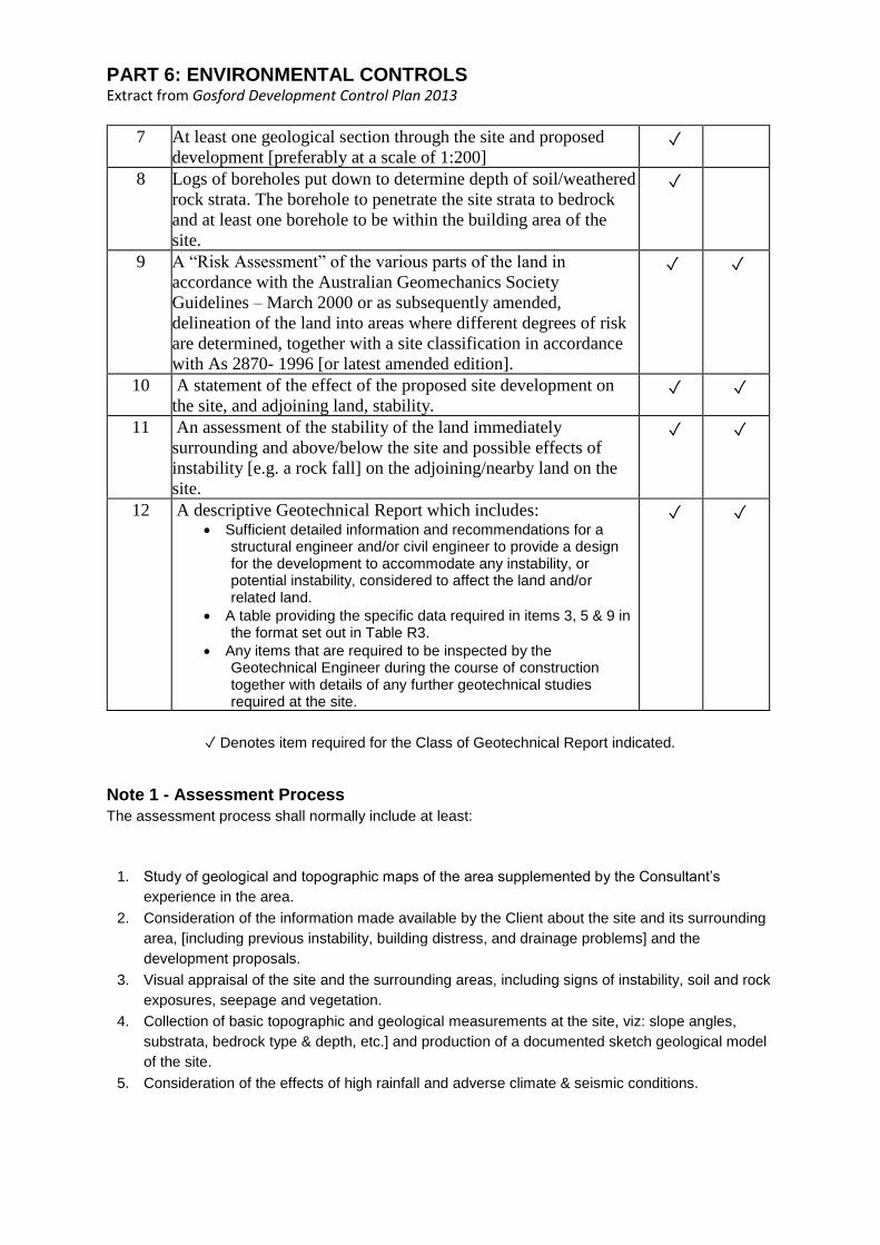
Table R2 – Minimum Information in Geotechnical Report
The following information is to be included at each level of report:
ITEM DESCRIPTION REPORT
Class
1
Class
2
1 A description of the Assessment process adopted and the work
undertaken to provide the assessment [See Note 1] ✓ ✓
2 A site description, including vegetation, bedrock outcrops, site
seepage & groundwater, existing development, etc. ✓ ✓
3 Description of site substrata and identification of the geological
formations present in accordance with standard geological
practice [e.g. Terrigal Formation (Rnt) of the Narrabeen Group]
✓ ✓
4 The depth to weathered bedrock over the site generally and
within the building area in particular. ✓ ✓
5 The site slopes observed [expressed in degrees] and maximum
site slope. Delineation of site into areas of common slope and
measured slope angles in the various areas.
✓ ✓
6 A site plan indicating relevant geological features & location of
proposed development on the land relative to those features
[preferably at a scale of 1:200].
✓
PART 6: ENVIRONMENTAL CONTROLS Extract from Gosford Development Control Plan 2013
7 At least one geological section through the site and proposed
development [preferably at a scale of 1:200] ✓
8 Logs of boreholes put down to determine depth of soil/weathered
rock strata. The borehole to penetrate the site strata to bedrock
and at least one borehole to be within the building area of the
site.
✓
9 A “Risk Assessment” of the various parts of the land in
accordance with the Australian Geomechanics Society
Guidelines – March 2000 or as subsequently amended,
delineation of the land into areas where different degrees of risk
are determined, together with a site classification in accordance
with As 2870- 1996 [or latest amended edition].
✓ ✓
10 A statement of the effect of the proposed site development on
the site, and adjoining land, stability. ✓ ✓
11 An assessment of the stability of the land immediately
surrounding and above/below the site and possible effects of
instability [e.g. a rock fall] on the adjoining/nearby land on the
site.
✓ ✓
12 A descriptive Geotechnical Report which includes: • Sufficient detailed information and recommendations for a
structural engineer and/or civil engineer to provide a design for the development to accommodate any instability, or potential instability, considered to affect the land and/or related land.
• A table providing the specific data required in items 3, 5 & 9 in the format set out in Table R3.
• Any items that are required to be inspected by the Geotechnical Engineer during the course of construction together with details of any further geotechnical studies required at the site.
✓ ✓
✓ Denotes item required for the Class of Geotechnical Report indicated.
Note 1 - Assessment Process
The assessment process shall normally include at least:
1. Study of geological and topographic maps of the area supplemented by the Consultant’s
experience in the area.
2. Consideration of the information made available by the Client about the site and its surrounding
area, [including previous instability, building distress, and drainage problems] and the
development proposals.
3. Visual appraisal of the site and the surrounding areas, including signs of instability, soil and rock
exposures, seepage and vegetation.
4. Collection of basic topographic and geological measurements at the site, viz: slope angles,
substrata, bedrock type & depth, etc.] and production of a documented sketch geological model
of the site.
5. Consideration of the effects of high rainfall and adverse climate & seismic conditions.

PART 6: ENVIRONMENTAL CONTROLS Extract from Gosford Development Control Plan 2013
Table R3 - Geotechnical Report Data
Assessed by: Assessment date:
Lot No: Street No: Street:
Suburb:
SITE DATA Land Area 1* Land Area 2*
Site Classification [AS 2870]:
Land slope [degrees]:
Geological abbreviation of
underlying bedrock type:
Description of surficial soil:
Type of Stability Risk [e.g.
landslip, rockfall, etc.]:
Risk Assessment [e.g. low,
moderate, etc]:
Geotechnical Inspections required during construction?
[yes/no]:
Risks from adjoining land:
Notes:
1. Additional land area columns to be added where site has more than two fundamental slopes.
2. One of the land areas described must contain the area within which building works are
proposed.
.
6.5.7 Greywater reuse in sewered single domestic premises
Greywater is composed of variable quantities of components of wastewater which may come from the
shower, bath tub, spa bath, hand basin, laundry tub, clothes washing machine, kitchen sink and
dishwasher. Greywater therefore is those components of sewage which do not come from a toilet or
urinal. Greywater contains impurities and micro-organisms derived from household and personal
cleaning activities. Because of high potential of greywater to contain pathogenic micro-organisms and
other materials it is considered by health authorities to be a potentially infectious and polluting waste
which people normally want to eliminate from the inside of their homes. It is an accepted practice and
community expectation in sewered areas that wastewater is drained to a sewer to promote sanitation
and hygiene in the home.
Greywater Treatment Systems:
There is now available in the market place greywater treatment systems that have been accredited by
NSW Department of Health. These systems treat water to a quality that allows water reuse to toilets,
clothes washing and hand held watering of gardens and lawns.
An application to install a greywater treatment system must be submitted to Council for assessment
and approval. An Approval to Operate must be issued by Council prior to the greywater system being
operated.
Greywater Diversion:
Diversion of untreated greywater through a system of pipes, tanks or patented devices must follow
NSW Health Department guidelines which states disposal or irrigation areas must be a sub-surface
system placed a minimum of 100mm deep with suitable buffer distances from boundaries, dwellings

PART 6: ENVIRONMENTAL CONTROLS Extract from Gosford Development Control Plan 2013
and sensitive features. Greywater diversion devices must not be installed where an existing on-site
sewage management facility is operating without a Permit To Install being issued by Council.
An Approval to Operate must be issued by Council prior to the operation of the system.
Greywater disposal by bucket from a washing machine:
During periods of drought this method may be acceptable to Council with a policy being reviewed and
determined from time to time according to water supply conditions.
The NSW Guidelines for Greywater Reuse in Sewered, Single Household Residential Premises are a
reference guide for greywater diversion and greywater treatment.
6.5.8 Site and Soil Investigation
6.5.8.1 Residential land category assessment
All existing systems within the Gosford City Council local government area have been classified as to
the risk they pose to health, amenity and their likely effect on the environment.
To determine the requirements specific to residential development not exceeding a capacity of 10
persons per system per allotment including subdivision of land and building work an assessment will
need to be undertaken in accordance with AS 1547:2000 On-site Domestic-Wastewater Management
and the Environment & Health Protection Guidelines On-site Sewage Management for Single
Households.
Generally a residential site will be initially assessed by Councils Technical Officer in accordance with
AS 1547:2000 On-site Domestic Wastewater Management and the Environment & Health Protection
Guidelines On-site Sewage Management for Single Households on submission of the application form
and fee.
In the case of high, medium and most low risk sites or commercial industrial situations Council will
require a report from a consultant who is suitably qualified for this type of work.
Gosford has some sites that are steep and/or may be susceptible to land slip where irrigation is
proposed. In these cases a report from a Geotechnical Engineer will be required.
6.5.8.2 Commercial, tourist and agricultural developments and residential developments with
occupancies greater than 10 persons assessment
On-site sewage management systems proposed for developments of this nature must produce
effluent quality of at least a secondary standard.
A development application for development within these categories will require a report addressing
the following heads of consideration:
• Outline the type and configuration of system proposed for the development including tank
capacities, the method of construction of tanks and the like.
• Provide information including calculations as to how the system will cater for the proposed
loading. The information must reference hydraulic and solid capacities in the system design.
• Provide a water balance analysis for the site.
• Provide nitrogen and phosphorous balances i.e. nutrient balances.
• Advise of the expected influent quality.
• Advise of the proposed outputs of the treated effluent prior to disposal in the LAA.
• Advise of any adverse chemical or biological inputs into the system and how the treatment
device will process these inputs and achieve the accepted effluent quality.

PART 6: ENVIRONMENTAL CONTROLS Extract from Gosford Development Control Plan 2013
• Demonstrate that the on-site sewage management systems meet the objectives of this Chapter
and related legislation.
• Provide a design including sizing calculations and construction methods regarding the LAA.
• Detail the mitigative measures proposed regarding protection of the system in the event of flood
if the land is susceptible.
• Submit a report from a suitably experienced geotechnical engineer or other suitably qualified,
practising professional in the field of commercial on-site wastewater disposal to indicate the
feasibility of the site and soil to accept and dispose of effluent in the form outlined in Gosford
City Council Guidelines.
6.6 Preservation of Trees or Vegetation
6.6.1 Introduction
6.6.1.1 Land to which the Chapter Applies
This chapter applies to all land in the Gosford City Local Government Area except land covered by
Clause 5.9(8) of Gosford Local Environmental Plan (LEP) 2014 and land covered by Acts other than
the Environmental Planning and Assessment Act relating to tree or vegetation removal.
6.6.1.2 Purpose of this Chapter
The purpose of this chapter is to prescribe, in conjunction with the provisions of Clause 5.9 of Gosford
LEP 2014 or the provisions of any other relevant planning instrument when development consent or a
tree works permit from Council is required for the actions of ringbarking, cutting down, topping,
lopping, removal, injuring or willfully destroying species of tree(s) or other vegetation.
Note
If tree(s) or other vegetation are not covered by this plan, development consent or a permit granted by
Council is not required to undertake the above actions.
6.6.1.3 Aims of the Chapter
1. To specify the species or types of tree(s) or vegetation that require development consent or a
tree works permit granted by Council for their ringbarking, cutting down, topping, lopping,
removal, injuring or wilful destruction.
2. To provide a framework for the protection of trees and native vegetation in Gosford City Local
Government Area.
3. To protect and enhance the environmental amenity, special landscape characteristics, unique
vegetation qualities and ecological values of Gosford City Local Government Area;
4. To outline a series of requirements and guidelines related to miscellaneous matters associated
with the operation of this Chapter.
6.6.1.4 Objectives of the Chapter
1. To preserve the amenity of the Gosford City Local Government Area through the preservation
trees and other vegetation.
2. To define Council's responsibilities and requirements with respect to the protection, retention
and replacement of trees and native vegetation.
3. To ensure proper consideration is given to trees and vegetation in planning, designing and
constructing development.
4. To minimise unnecessary injury to, or destruction of, trees and vegetation.
5. To facilitate the removal of undesirable exotic plants, noxious weeds, dangerous trees and other
inappropriate plantings.

PART 6: ENVIRONMENTAL CONTROLS Extract from Gosford Development Control Plan 2013
6. To specify the requirements for the submission of sufficient and relevant information by those
who wish to ringbark, cut down, top, lop, remove, injure or wilfully destroy any tree or other
vegetation.
6.6.1.5 Application of the Chapter
A Tree Works Permit will be required for the ringbarking, cutting down, topping, lopping, pruning,
removal, injuring or willfully destroying of tree(s) (as defined in the Definitions Section of this plan) that
is ancillary to the consented use of the land.
Development consent will be required from Council for the ringbarking, cutting down, topping,
lopping, pruning, removal, injuring or willfully destroying of vegetation and tree(s) that is not ancillary
to the consented use of the land nor is part of a development application for a development permitted
with the consent of Council in the zone that applies to the land.
A Complying Development certificate is taken to satisfy any requirement for a permit or
development consent to remove or prune a tree or other vegetation if the tree or vegetation:
1. is within 3m of the proposed development, and
2. is less than 6 metres high, and
3. is not listed on Council's Significant Tree Register.
Heritage Trees - Development consent is required from Council for the ringbarking, cutting down,
topping, lopping, removal, injuring or willful destruction of trees listed as a heritage item or are located
within a heritage conservation area.
Significant Trees - Proposals for the ringbarking, cutting down, topping, lopping, removal, injuring or
willful destruction of listed Significant Trees require a Tree Works permit. All applications must be
supported by a detailed arborcultural report that is to consider and discuss all options (unless Council
is satisfied it is a risk to human life or property). If consent is to be granted a report is to be forwarded
to senior management for determination. Refer to Council's Significant Tree Register.
See link below.
www.gosford.nsw.gov.au/environment/trees/significant_tree_register
Exempt Tree Removal and Pruning - Council consent may be assumed for removal and/or pruning
of the following;
1. trees within three (3) metres of an approved building (measured one (1) metre above ground
level and between the face of the wall and the part of the trunk nearest the building), providing
the tree species is not a threatened species or not listed on Council's Significant Tree Register
or Heritage Item;
2. dead trees or pruning of dead branches;
3. tree species listed in Appendices 1 or 2;
4. branches directly overhanging the roofline of an approved building (in accordance with
Australian Standard AS4373);
5. branches within 1m around electricity and/or telecommunication wires.

PART 6: ENVIRONMENTAL CONTROLS Extract from Gosford Development Control Plan 2013
6.6.2 Definitions
Approved building - A building or part of a building which has been approved by Council under the
Environmental Planning and Assessment Act or Local Government Act, or has otherwise been
lawfully constructed, but doesn't include:-
1. A manufactured home, movable dwelling or associated structure;
2. A temporary structure within the meaning of the Local Government Act:
3. Any structures included in the list of "exempt development".
Clearing is defined as cutting down, felling, thinning, logging, removing, killing, destroying, poisoning,
ringbarking, uprooting, underscrubbing or burning native vegetation.
Native Vegetation means any of the following types of indigenous vegetation: trees (including any
sapling or shrub, or any scrub), understorey plants, groundcover (being any type of herbaceous
vegetation) or plants occurring in a wetland.
Tree Long lived woody perennial plant greater than 3m in height with one or relatively few main stems
or trunks.
6.6.3 Application Matters
6.6.3.1 Information Requirements
The following information is required to be submitted:
1. with an application for those activities requiring a development application; and
2. with a Tree Works Application, if upon review of the Tree Works Application, Council's Tree
Management Officers consider such information is necessary for the assessment of the
application.
6.6.3.2 Tree Locations and Schedule
Tree Locations & Schedule is required when a Development Application involves works which may
affect trees on the property, and/or trees within 5m of the proposal on an adjoining property.
An accurate Tree Locations & Schedule is necessary as it can form the basis of a tree
removal/retention condition of consent.
A Tree Locations & Schedule locates, identifies and provides basic data on existing trees on and
adjacent to a site. It must include all trees that maybe affected by proposed buildings, access,
services and bushfire asset protection zones.
The Tree Locations & Schedule is to indicate the proposed action of the identified trees (remove or
retain). Crown spread of trees is to be drawn on the plan and shown as a dashed line for trees to be
removed, or an unbroken line for trees to be retained.
All trees are to be plotted (by land survey) and numbered on a Development Applications; Site
Analysis plan, Survey plan and Landscape plan. The tree schedule (sample below) can be on the
plan or attached to the applications documentation. The number of each tree on the plan is to
correspond with the numbered tree schedule and the tag of each tree on site.

PART 6: ENVIRONMENTAL CONTROLS Extract from Gosford Development Control Plan 2013
Sample tree schedule corresponding to survey plan
No Botanical Name Common Name Height
(m)
DBH
(mm)
Action
1 Eucalyptus
punctata
Grey Gum
12
600
Remove
2 Corymbia
maculata
Spotted Gum
22
700
Retain
3 Eucalyptus
robusta
Swamp Mahogony
18
900
Retain
6.6.3.3 Arborist's Report
An Arborist’s Report provides technical comment on specific tree-related issues, particularly regarding
the health and condition of trees and can include recommended strategies for for retaining and
protecting trees close to proposed developments.
An Arboriculture Report can provide supporting evidence of defects in trees to justify an application
for removal.
For development proposals an arboricultural report must consider Section 2 of Australian Standard
Protection of trees on development sites AS 4970-2009 and is required when:-
• More than ten (10) trees (over 3m in height) are nominated for removal;
• Works are to occur within 5m of trees to be retained, that have a DBH (Diameter at Breast
Height) greater than 500mm;
• As requested by Council's Tree Assessment Officer.
An Arboricultural Report must be prepared by a qualified arborist suitably experienced and competent
in arboriculture, having acquired through training, qualification (minimum Australian Qualification
Framework (AQF) Level 5, Diploma of Horticulture (arboriculture) where deemed necessary by the
Assessing Officer.
6.6.3.4 Flora and Fauna Impact Assessment Report
Where the clearing of trees and native vegetation is proposed a Flora & Fauna Impact Assessment
Report that addresses Section 5A of the Environmental Planning and Assessment Act 1979 may be
required.
The Flora & Fauna Impact Asessment Report is to be prepared in accordance with Flora and Fauna
Survey Guidelines: Lower Hunter Central Coast Region (2002) (Lower Hunter Central Coast Regional
Environmental Management Strategy) or any guidelines prepared by the NSW State Government for
assessment of matters under the Threatened Species Conservation Act 1995.

PART 6: ENVIRONMENTAL CONTROLS Extract from Gosford Development Control Plan 2013
6.6.4 Assessment Criteria
The following provides the basis by which Council will assess Development Applications or Tree
Works Permit Applications.
6.6.4.1 Assessment Criteria for a Development Application and Tree Works Permit
Applications
1. Whether sufficient supporting information (as per 6.6.3) has been provided.
2. Whether the development has an impact on:-
1. native flora and fauna and its habitat, and
2. threatened species, critically and endangered ecological communities, populations and
their habitats, and
3. regionally significant vegetation and
4. a habitat corridor, waterways, riparian land or wetland.
1. Whether the development is designed, sited and managed to avoid potential adverse
environmental impacts;
2. If a potential adverse environmental impact cannot be avoided, has the development;
1. been designed and sited so as to have minimum adverse impact, and
2. incorporated effective measures so as to have minimal adverse impacts, and
3. mitigated any residual adverse environmental impact through the restoration of any
existing disturbed or modified area on the site.
1. Whether the trees or other vegetation contributes to the natural or desired character of the area
as identified in the Character chapter in this DCP;
2. Has considered the provisions of relevant legislation and relevant Council plans and policies;
3. Whether the trees or other vegetation forms part of a heritage item, or is within a heritage
conservation area.
4. The potential hazard to persons or property in the context of;
1. the structural soundness of the particular tree, and/or
2. the characteristics and history of the particular species, and/or
3. such other conditions such as ground conditions, building proximity, etc which may give
rise to a hazardous situation.
1. The vitality, condition and useful life expectancy (ULE) of the tree in respect to the practicality of
remedial actions;
2. The existence of potential for visual or sight hazard as a result of proximity to a roadway,
intersection or a driveway, where pruning is inappropriate;
3. The demonstrated need for reasonable solar access to dwellings, solar appliances and cloths
drying areas;
4. The replacement or pruning of a tree given its location or proximity to utility lines such as
overhead power wires, sewer pipes, etc;
5. Whether the tree is an ornamental of fruiting variety and is no longer fulfilling its original purpose
in the location in which it had been planted;
6. Species which by natural propagation methods are likely to create a threat to the landscape
environment;
7. Any additional or replacement planting which has been or is to be undertaken on the land;
8. Whether removal or pruning of trees has been proposed to minimize impacts on better quality
trees to be retained;
9. Whether the establishment and/or maintenance of a Bushfire Asset Protection Zone has been
supported by a report from the Rural Fire Service or qualified bushfire consultant.

PART 6: ENVIRONMENTAL CONTROLS Extract from Gosford Development Control Plan 2013
10. Provided that no significant hazard or other safety issues also apply, the following shall not
generally be considered as valid reasons to remove a tree:
1. Leaf drop (into gutters and downpipes – pools, lawns and the like);
2. To increase natural light;
3. To improve street lighting of private property;
4. To enhance views;
5. To reduce shade;
6. To reduce fruit, resin or bird droppings on cars;
7. Minor lifting of driveways, brick fences and paths by tree roots;
8. To erect a fence;
9. Bushfire hazard control which has not been verified by Council;
10. Potential damage to sewer mains unless supported by written expert advice and only
where reasonable alternatives are not feasible (e.g.: relocate, sleeving);
11. Termite damage to trees unless supported by written expert advice from a qualified pest
controller and only where reasonable alternatives are not feasible (eg: treatment of
pest).
6.6.4.2 Underscrubbing subject of a Development Application
Where an application for tree or other vegetation removal consisting of underscrubbing is made the
following conditions will be included:
1. Underscrubbing is to be carried out with the use of rubber tyred machinery only;
2. Provision for exclusion zones for intermittent or permanent watercourses;
3. Provision for retention of all trees greater than 3 metres in height;
4. Substantial clumps of vegetation to be retained in cleared areas. These will be required to be
fenced off to prevent intrusion by stock and/or machinery;
5. Fallen timber is to be recycled (such as through chipping, grinding, mulching), and left on site or
otherwise removed from the site for an approved recycling process. Temporary windrows or
heaps are to be placed across contours and be a minimum of 20 metres from any vegetation
which is to be retained;
6. No vegetation is to be pushed into those areas of no disturbance (exclusion zones), particularly
drainage lines;
7. Removal of noxious weeds (see Appendix 2) is to be by hand implements only in those areas to
be retained (i.e. in the exclusion zones);
8. Windbreaks will not be permitted to be incorporated into the clearing scheme except where
identified in an approved Rehabilitation Plan;
9. All erosion control measures to be in place prior to clearing;
10. If there is to be a time lapse between clearing and sowing or planting, then a suitable cover crop
shall be required to be planted.
6.6.5 General Provisions
6.6.5.1 Tree Protection on Development Sites
Council recommends that Australian Standard - Protection of trees on development sites AS4970,
2009, be used for guidance in regard to integration between trees and construction. The document is
considered to describe the best practices for planning and protection of trees on development sites.
6.6.5.2 Tree Replenishment
Where trees are proposed for removal or there are no other existing canopy trees on site, Council
expects a degree of tree replenishment to occur where practical. Each site should contain tree(s)
capable of achieving a minimum height of 10 metres. Where sufficient existing canopy trees are to be
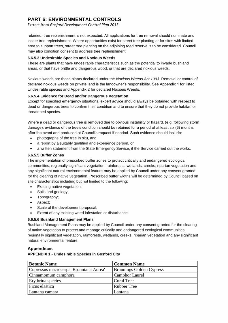
PART 6: ENVIRONMENTAL CONTROLS Extract from Gosford Development Control Plan 2013
retained, tree replenishment is not expected. All applications for tree removal should nominate and
locate tree replenishment. Where opportunities exist for street tree planting or for sites with limited
area to support trees, street tree planting on the adjoining road reserve is to be considered. Council
may also condition consent to address tree replenishment.
6.6.5.3 Undesirable Species and Noxious Weeds
These are plants that have undesirable characteristics such as the potential to invade bushland
areas, or that have brittle and dangerous wood, or that are declared noxious weeds.
Noxious weeds are those plants declared under the Noxious Weeds Act 1993. Removal or control of
declared noxious weeds on private land is the landowner’s responsibility. See Appendix 1 for listed
Undesirable species and Appendix 2 for declared Noxious Weeds.
6.6.5.4 Evidence for Dead and/or Dangerous Vegetation
Except for specified emergency situations, expert advice should always be obtained with respect to
dead or dangerous trees to confirm their condition and to ensure that they do not provide habitat for
threatened species.
Where a dead or dangerous tree is removed due to obvious instability or hazard, (e.g. following storm
damage), evidence of the tree’s condition should be retained for a period of at least six (6) months
after the event and produced at Council’s request if needed. Such evidence should include:
• photographs of the tree in situ, and
• a report by a suitably qualified and experience person, or
• a written statement from the State Emergency Service, if the Service carried out the works.
6.6.5.5 Buffer Zones
The implementation of prescribed buffer zones to protect critically and endangered ecological
communities, regionally significant vegetation, rainforests, wetlands, creeks, riparian vegetation and
any significant natural environmental feature may be applied by Council under any consent granted
for the clearing of native vegetation. Prescribed buffer widths will be determined by Council based on
site characteristics including but not limited to the following;
• Existing native vegetation;
• Soils and geology;
• Topography;
• Aspect;
• Scale of the development proposal;
• Extent of any existing weed infestation or disturbance.
6.6.5.6 Bushland Management Plans
Bushland Management Plans may be applied by Council under any consent granted for the clearing
of native vegetation to protect and manage critically and endangered ecological communities,
regionally significant vegetation, rainforests, wetlands, creeks, riparian vegetation and any significant
natural environmental feature.
Appendices
APPENDIX 1 - Undesirable Species in Gosford City
Botanic Name Common Name
Cupressus macrocarpa 'Brunniana Aurea' Brunnings Golden Cypress
Cinnamomum camphora Camphor Laurel
Erythrina species Coral Tree
Ficus elastica Rubber Tree
Lantana camara Lantana

PART 6: ENVIRONMENTAL CONTROLS Extract from Gosford Development Control Plan 2013
Ligustrum ovalifolium Narrow Leaved Privet
Ligustrum lucidum Broad Leaved Privet
Pinus radiata Radiata Pine
Phyllostachys spp Bamboo
Ricinus communis Castor Oil Plant
Robinia pseudoacacia Black Locust/False Acacia
Salix spp. (all species except S.stricta) Willows
Schefflera actinophylla Umbrella Tree
Syagrus romanzofianum Cocos palm (formally Arecastrum
romanzofianum)
Tecoma stans Tecoma
Non-native fruit trees
APPENDIX 2 - Noxious Plants
As declared Noxious by the order of the Minister for Agriculture and gazetted in accordance with the
Noxious Weeds Act 1993.
Botanical Name Common Name
Acacia karoo Karoo Thorn
Ageratina adenophora Crofton Weed
Ageratina riparia Mistflower
Alternanthera philoxeroides Alligator Weed
Cambomba spp. (not Cabomba furcata) Cabomba (not Pink Cabomba)
Cenchrus incertus & Cenchrus longispinus Spiny Burr Grass
Centaurea nigra Black Napweed
Centaurea maculosa Spotted Napweed
Cestrum parqui Green Cestrum
Chromolaena odorata Siam Weed
Chrysanthemoides monilifera subsp.
monilifera
Boneseed
Chrysanthemoides monilifera subsp.
rotunda
Bitou Bush
Cuscuta campestris. Golden Dodder
Eichornia crassipes Water Hyacinth
Emex australis Spiny Emex
Equisetum spp. Horsetail
Gymnocoronis spilanthoides Senegal Tea Plant
Harrisia spp. Harrisia Cactus
Hieracium spp. Hawkweed
Hypericum perforatum St Johns Wort
Kochia scoparia (not K scoparia subsp.
Tricophylla)
Kochia
Lagarosiphon major Lagarosiphon
Ludwidgia peruviana Peruvian Water Primrose
Lycium ferocissimum African Boxthorn
Miconia spp Miconia
Nassella tenuissima syn Stipa Mexican Feather Grass
Opuntia spp. Prickly Pear

PART 6: ENVIRONMENTAL CONTROLS Extract from Gosford Development Control Plan 2013
Orobanche spp Broomrape
Parietaria judaica Pellitory/Asthma Weed
Parthenium hysterophorus Parthenium Weed
Pistia stratiotes Water Lettuce
Rubus fruticosus (agg. spp.) Blackberry
Salvinia molesta Salvinia
Sorghum x almum Columbus Grass
Sorghum halepense Johnson Grass
Sporobolus indicus var major Giant Parramatta Grass
Toxicodendron succedaneum Rhus Tree
Ulex europaeus Gorse
Xanthium spp. Burrs - Noogoora, California, Bathurst,
Cockle
APPENDIX 3 - Regionally Significant Vegetation
Regionally Significant Vegetation
(Comparable Communities and Sub-Communities in
Gosford LGA)
Vegetation
Community
Description
(Bell 2004)
Coastal Headland Gully Scrub E51e
Coastal Headland Low Forest E51c
Coastal Headland Shrubland E51b
Coastal Narrabeen Ironbark Forest E6b
Coastal Narrabeen Moist Forest - Acacia regrowth E6aiii
Coastal Narrabeen Moist Forest - Basalt variant E6aiii
Coastal Sand Banksia Scrub E50b
Coastal Sand Foredune Scrub E50a
Coastal Sand Wallum - Heath E34ai
Coastal Sand Wallum - Heath - intermediate variant E34aii
Coastal Headland Paperbark Scrub E51d
Coastal Sand Beach Spinifex E53
Estuarine Mangrove Scrub E47
Hawkesbury Dwarf Apple Woodland E28
Katandra Hawkesbury Woodland E26b
Killcare Hawkesbury Woodland E26c
Narrabeen Coastal Peppermint Forest E22c
Sandstone Ranges Gully Rainforest E2
Somersby Plateau Forest E26d
Swamp Paperbark Thicket E100
Tumbi Spotted Gum Ironbark Forest E15ai
Tumbi Spotted Gum Ironbark Forest - Acacia regrowth E15aii
Wamberal Low Open Heath Forest E101
Bell S.A.J. (2004) The Natural Vegetation of the Gosford Local Government Area, Central Coast, New
South Wales: Vegetation Community Profiles Unpublished Report to Gosford City Council, April 2004,
Eastcoast Flora Survey.
6.7 Water Cycle Management

PART 6: ENVIRONMENTAL CONTROLS Extract from Gosford Development Control Plan 2013
6.7.1 Land to which Chapter Applies
This chapter applies to all development in the City of Gosford that requires consent.
6.7.2 Purpose
The purpose of this plan is to minimise the impact of development on the natural predevelopment
water cycle. This will lead to more sustainable outcomes that will protect the environment.
The water cycle (or hydrological cycle) refers to all the processes and forms that water undertakes as
it is used within the built and natural environment. Important water aspects include:
• Stormwater (including groundwater)
• Water-borne pollutants
• Wastewater
• Flood waters
• Water supply
• Water dependant ecosystems
This chapter of the DCP has been prepared to facilitate the application of the following principles of
Water Sensitive Urban Design (WSUD), Integrated Water Cycle Management (IWCM) and Flood
Mitigation in the LGA:
1. Maintain and restore natural water balance whilst reducing the cost of providing and maintaining
water infrastructure in a sustainable and efficient manner.
2. Reduce risk to life and damage to property by restricting and controlling building and other
development so that it minimises risks to residents and those involved in rescue operations
during floods.
3. Reduce nuisance and high level flooding and the cost of providing and maintaining flood
mitigation infrastructure whilst improving water quality in streams and groundwater.
4. Reduce potable water demand by using stormwater as a resource.
5. Protect and enhance natural water systems (creeks, rivers, wetlands, estuaries, lagoons and
groundwater systems).
6. Protect and enhance the water quality, by improving the quality of stormwater runoff from the
urban catchments.
7. Integrate stormwater management systems into the landscape in a manner that provides
multiple benefits, including water quality protection, stormwater retention and detention, public
open space and recreational and visual amenity.
6.7.3 Objectives
The objectives of this chapter are to:
• Provide direction and advice to applicants in order to facilitate WSUD,IWCM and Flood
Mitigation within the development application process
• Provide design principles that will assist development to meet the purpose of this chapter of the
DCP.
• Provide objectives and performance targets for specific water management elements including
water conservation, retention / detention, stormwater quality, and flooding caused by Local
Overland Flooding, Mainstream Flooding or Storm Surge.

PART 6: ENVIRONMENTAL CONTROLS Extract from Gosford Development Control Plan 2013
6.7.4 Relationship to other Plans
This chapter of the DCP is to be read in conjunction with:
• Gosford City Council Water Cycle Management Guidelines.
• State Environmental Planning Policy - Building Sustainability Index: (BASIX) 2004
• NSW Government Floodplain Development Manual.
• Water Management Act 2000.
6.7.5 Background
• Urbanisation has led to increased stormwater flows in urban creeks and the consequent impact
on flooding, creek degradation and public safety.
• Stormwater management has traditionally been focused on conveying stormwater runoff safely
away from developed areas through pipes and drains. With progressive development, natural
waterways in urbanising catchments have become increasingly taxed in their ability to convey
the significant increases in quantity and rate of stormwater runoff generated, with bank erosion
and increased frequency of flooding the obvious symptoms (ARQ 2006, p.1-1). Continued
increase in the size of pipes and channels is not ecologically sustainable or financially
sustainable, and it can lead to even greater levels of hazard.
• In recognition of this issue Council has adopted Water Sensitive Urban Design (WSUD) as a
new way of thinking for managing stormwater management (Argue 2004). It recognises:
• Flooding and stormwater runoff that can cause risk to life and damage to property, as the issue
of first importance.
• Rainfall mobilises significant quantities of sediment, heavy metals, hydrocarbons and nutrients,
which must be appropriately managed before it enters urban waterways and recreational
receiving waters.
• Stormwater runoff is a valuable, readily available resource, which, when properly managed, can
replace significant quantities of mains water.
• Fundamental to the principles of WSUD is that of source control of stormwater. It is through
controlling stormwater runoff at the source, whether that source is the massive roof area of a
commercial development or the carriageway of a major road or the site of a typical residential
development, that the objectives of WSUD are achieved.
• This plan seeks to use source control to replicate, as practically as possible, the pre-
development water cycle of the development site. The objective is to retain part of the runoff
from rainfall events on site and redirect it to better mimic the natural water cycle. The retained
water can be redirected for domestic use, industrial use, or the natural processes of infiltration,
percolation, evaporation, or transpiration. The remaining surface runoff leaving the development
site will then better mimic the predevelopment runoff in terms of quantity, rate and water quality.
Water cycle management focus changes depending on the size or frequency of storm events, as
shown below in Figure 1, which provides the scope for this plan.

PART 6: ENVIRONMENTAL CONTROLS Extract from Gosford Development Control Plan 2013
Figure 1 - Water Cycle Management Focus Areas
6.7.6 Water Cycle Management Plan
6.7.6.1 Intent
All developments that require consent will be required to demonstrate compliance with the targets in
Table 1.

PART 6: ENVIRONMENTAL CONTROLS Extract from Gosford Development Control Plan 2013
6.7.6.2 Objective
The Water Cycle Management Plan (WCMP) is required for all developments with the exception of
exempt developments and is to demonstrate compliance with the development control targets listed in
Table 1 and described throughout this chapter.
6.7.6.3 Application Requirements
Applicants are encouraged to discuss development proposals with Council’s Development
Assessment staff at an early concept stage, prior to lodgement of a development application. This
pre-lodgement discussion will assist in identifying and addressing any matters that may otherwise
increase processing time. The following matters are to be taken into consideration during the
preparation of WCMPs:
• safety – public safety and OH & S considerations; and
• maintenance – development of maintenance and monitoring regime for the management of
WSUD elements.
Requirements for Water Cycle Management information required in support of a Development
Application vary for different scales of proposed development, and the mechanism or approach
adopted in the determination of management elements required to comply with applicable
development control targets. The options available to proponents of different types / scales of
development are described below.
Type 1 - Smaller Scale Developments
Type 1 - Smaller Scale Developments includes the following development:
• Alterations, additions, ancillary structures & second storey additions with regard to all works to
any existing building or development where the net proposed development area is equal to or
greater than 50m2 for other than exempt development. After 01/03/2007 (date of operation of the
superseded DCP 165 - Water Cycle Management), each site will be restricted to a one-off
development approval of less than 50m2 not requiring rainwater tanks. Once the combined total
of all applications submitted after the date of operation of this plan reaches 50m2 then the
requirements of this chapter of the DCP shall be applied.
• Single residential dwellings & dual occupancy
• Medium Density or High density developments that create less than 10 dwellings or involve the
development of 2000m2 of land or less.
• .
• Urban subdivisions that create less than 10 residential lots or involve the development of
2000m2of land or less.
• Industrial / Commercial Development that involves the development of 2000m2 of land or less.
Proponents of developments in the Type 1 category are required to demonstrate compliance against
applicable stormwater targets through one of the following options:
• adoption of Council’s Deemed to Comply criteria, as outlined in Section 6.7.6.3.1 or
• submission of a detailed WCMP Strategy, as described in Section 6.7.6.3.2
Type 2 - Significant Developments
Type 2 - Signifcant Development includes the following development:
• Medium Density or High density developments that create equal to or more than 10 dwellings
and / or involve the development of 2000m2 of land or more.
• .
• Urban subdivisions that create equal to or more than 10 residential lots and / or involve the
development of 2000m2 of land or more.
PART 6: ENVIRONMENTAL CONTROLS Extract from Gosford Development Control Plan 2013
• Industrial / Commercial developments including alterations or additions that exceed 2000m2.
Development applications for all Type 2 developments require the preparation and submission to
Council of a detailed WCMP Strategy. Guidance on the scope and content of a WCMP Strategy is
presented in Section 6.7.6.3.2.
6.7.6.4 Deemed to Comply
Proponents of small-scale developments may avoid the requirement for site stormwater modelling by
adopting one of the following ‘deemed to comply’ solutions:
Standard Design Parameters for Deemed to Comply solutions
Standard design parameters for Deemed to Comply solutions are provided in the following chapter.
Supporting Information
If a deemed to comply solution is adopted, the following information (if applicable) should be
submitted as part of the development application:
• Site plan showing roofed, other impervious areas, topography and the location of easements &
underground services,
• Drainage plan showing catchments, drainage systems, and discharge point including
calculations of runoff (with and without blockage),
• Overland runoff flow paths (across the site and beyond the site boundaries clearly shown)
• Setback distances from buildings to infiltration devices and drainage easements,
• Demonstrate setback distances from buildings to top of bank of creeks,
• Water Saving Target: demonstrate compliance
• Retention target: Show rainwater tank/s, infiltration devices, and any stormwater capture,
storage and slow release devices (including a table showing sizes, and details for each, along
with calculations which demonstrate achievement of stormwater capture volumes and
replenishment times for each device and for the overall site.
• On Site Detention Target: Detail the OSD device including size, outlet control and configuration,
along with calculations which demonstrate the achievement of the predevelopment peak
flowrates
• Stormwater quality target: Show location of each landscaping pollution retention measure
(including a table showing calculations, sizes, and details for each; along with a table showing
calculations of the overall Site Discharge Index).
• Local Overland Drainage Target: Show raised floor levels, cut & fill, overland flow paths, and
discharge points.
• Flooding Targets: Show details of applicable targets, including: floor levels, flood impacts,
access & parking (if applicable).
• BASIX certificate for residential developments,
• for commercial and industrial sites a summary of water conservation measures to be applied on
site, including an estimate of total water demands and expected savings associated with water
conservation measures / alterative water sources , as well as detail on how water demands will
be managed and monitored,
• plans and cross-sectional drawings of stormwater treatment systems, showing inlets, outlets
and overflow points (these may be prepared from standard drawings, with site-specific levels
and dimensions included).
Further assistance in the preparation of a Deemed to Comply Solution is outlined in this chapter of the
DCP and contained within the supporting documents:

PART 6: ENVIRONMENTAL CONTROLS Extract from Gosford Development Control Plan 2013
• HCCREMS (2007) Practice Notes
6.7.6.5 WCMP Strategy
Discussions with Council are encouraged at an early stage in the development application process to
discuss and agree on the overall design approach before a detailed WCMP Strategy is prepared. The
intent is to have the locality analysis available so that parameters can be agreed rather than providing
the analysis only at the development application stage, thus saving time and costs associated with
revisions and major modifications.
The aim of the consultation process is to provide direction and guidelines to the applicant, and to
provide advice on Council’s requirements. The level of consultation required will largely depend on
the size and the complexity of the development.
Water Sensitive Urban Design Strategy
A WCMP Strategy is a written report and associated plans detailing potable water saving and
stormwater / flooding management measures that are to be implemented on the site. The strategy is
to include, at a minimum, the following detail:
• Background information - Summarise any background information available, including
previous studies, concurrent studies, mapping data.
• Site context – identify catchments, drainage lines and receiving environments (both within and
downstream of the site). Characterise the ecological values of the site and its receiving
environments.
• Proposed development - Describe the proposed development at the site, including site
boundaries, proposed land uses, densities, population, infrastructure, development staging.
• Water Cycle Management objectives - Identify the Water Cycle Management (including
flooding / overland flow) objectives and targets that apply to the proposed development.
• Constraints and opportunities - Identify the key constraints and opportunities for water
management on the site, including flooding. This should include the identification of natural
watercourses and other sensitive environments within the site that should be preserved and/or
remediated by the development.
• Best planning practices – the capital and life-cycle costs of infrastructure required to meet
Water Cycle Management targets can be minimised by considering site planning opportunities
early in the planning process.
• Water conservation - This section should demonstrate how the potable water conservation
targets will be met, and how potable water will be supplemented with roofwater, treated
stormwater and/or wastewater.
• Stormwater management - This section should demonstrate how the WCMP stormwater
quality targets will be met. It should include stormwater quality and flow modelling results and
identify the location, size and configuration of stormwater treatment measures proposed for the
development.
• Integration with the urban design - The WCMP Strategy should outline how management
elements will integrate with the urban design.
• Costs - Prepare capital and operation and maintenance cost estimates of proposed water cycle
management measures. Both typical annual maintenance costs and corrective maintenance or
renewal/adaptation costs should be included.
• Operation and Maintenance Plan – should outline inspection and maintenance requirements
to ensure proposed measures remain effective.
Assistance in the preparation of a WCMP Strategy is contained within the supporting documents:

PART 6: ENVIRONMENTAL CONTROLS Extract from Gosford Development Control Plan 2013
• HCCREMS (2007) Practice Notes
Modelling parameters for the determination of the size and configuration of WSUD elements must be
in accordance with the guidance titled:
• MUSIC Modelling Guidelines for New South Wales (eWater, 2009)
Guidance on meeting the DCP objectives is contained in the supporting technical guidelines of the
Gosford City Council's DCP 2013.
• Managing Urban Stormwater: Treatment Techniques (IPWEA, 2008)
• Australian Runoff Quality (Engineers Australia, 2005)
6.7.7 Development Control Targets
6.7.7.1 Water Conservation Target
6.7.7.1.1 Intent
Reduce potable water demand by 40%
6.7.7.1.2 Recommended Application
Specify water saving devices and potable water substitution option, where applicable, for new
developments.
6.7.7.1.3 Deem to Comply
Any SEPP BASIX 2004 (BASIX) affected development is to demonstrate compliance with BASIX.
Further information on details of types of development requiring a BASIX Certificate or to produce a
certificate for your proposed development go to www.basix.nsw.gov.au.
Developments not affected by BASIX: a water saving target of 40% (consistent with the BASIX
requirement), this must include the following:
• Ensure any water use fittings demonstrate minimum standards defined by the Water Efficiency
Labelling and Standards (WELS) Scheme. Minimum WELS ratings are:
• 4 star dual-flush toilets
• 3 star showerheads
• 4 star taps (for all taps other than bath outlets and garden taps)
• 3 star urinals
• Water efficient washing machines and dishwashers are to be used wherever possible.
• Incorporate dual reticulation for toilet flushing, laundry, irrigation. Development within the
Gosford CBD will be required to provide dual plumbing throughout.
Example applications: Runoff recycling in nursery, Erina

PART 6: ENVIRONMENTAL CONTROLS Extract from Gosford Development Control Plan 2013
Recycled greywater - water from showers is treated and reused for toilet flushing at Terrigal
Surf Life Saving Club
Harvested stormwater used in public open space, Kogarah, Sydney
6.7.7.2 Retention Target
6.7.7.2.1 Intent
To mimic the natural catchment hydrology from all development sites, in terms of:
• Quantity: the annual volume of stormwater reaching natural creeks and waterways.
• Rate: the peak flow rates leaving the site
• Response: the time it takes for rain to runoff the site.
In technical terms the intent is to mimic the pre-development runoff losses such that the post-
development and pre-development runoff hydrographs are similar in terms of volume, peak and
shape for the full range of design events.
6.7.7.2.2 Objective
Capture and retain runoff from impervious surfaces (whether roof, paving or road carriageway), retain
it for a relatively long time, and slowly release it elsewhere in the water cycle within 7 days.

PART 6: ENVIRONMENTAL CONTROLS Extract from Gosford Development Control Plan 2013
6.7.7.2.3 Recommended Application
The Stormwater Retention Volume may be adapted to individual site constraints, provided that the
required volume from all impervious areas is captured before leaving the site. Management of
captured stormwater will involve:
• Rainwater capture (from roof areas), storage (in rainwater tanks) and reuse (for domestic or
industrial purposes)
• Stormwater capture (from external impervious areas), storage (in landscaping features, such as
terraced gardens, bioretention - raingardens, or stormwater tanks) and slow release (through
the natural processes of infiltration, percolation, evaporation, or transpiration)
6.7.7.2.4 Deemed to Comply
Show on the Water Cycle Management Plan the Stormwater Retention Volume, which can be
calculated by the formula below, or interpolated from Table 2, with the exception of pools and outdoor
spas.
V = 0.01A(0.02F)2 V = Stormwater Retention Volume (m3)
A = Total Site Area (m2)
F = Fraction Impervious (%)
Show locations of each rainwater or stormwater capture device to treat each impervious area
(whether rainwater tanks, stormwater tanks, raingardens, or soak away areas). Overflows from each
device should preferably be via a suitably designed "natural" overland flow path.
Include a table summarizing sizes and details for each, along with calculations which demonstrate
achievement of stormwater capture volumes and replenishment times for each device and for the
overall site. Refer to example retention calculations below.
Installation of following require:
• a pool only - rainwater tank with a minimum volume of 2.0m3 (2000L).
• an outdoor spa - rainwater tank with a minimum volume of 1.0m3 (1000L)
• a pool and an outdoor spa - rainwater tank with a minimum 2.5m3 (2500L)hav

PART 6: ENVIRONMENTAL CONTROLS Extract from Gosford Development Control Plan 2013
Notes
• For the purposes of this DCP household water usage is assumed to be related to the size of the
roof area (including covered pergolas and awnings). For a typical dwelling the water use is 1000
litres per day for a roof area of 200m2. On this basis, the assumed water use per square
metre of roof area is 5 L/day or 35 L/week.
• Higher levels of rainwater reuse help ensure that there will be adequate volume available in the
rainwater tank to help retain the roof runoff without the tank overflowing.
• Retro-fitting an entire house to rainwater can be very cost-effective as it does not require dual-
plumbing.
• The rainwater tank must be sized to have a rainwater storage volume not less than that required
by any BASIX certificate issued for the development, and configured in accordance with the
requirements of that certificate.
• For the calculation of infiltration during the storm event, the design storm is assumed to be a
30mins duration event.
6.7.7.2.5 Examples Retention Volume Calculations
1. A house on a 800m2 block with a roof area of 250m2 and an external paved area of 150m2. The
rainwater tank is plumbed to outdoor taps, toilets and the washing machine. External retention is
proposed by directing runoff from paved areas into a terraced garden (Size 12m2; Soil: sandy
loam; raised sides to temporarily contain runoff).
Retention volume required = 50% impervious on 800m2 block
(Table 2)
= 8000 L
Rainwater reuse over 1 week = 35 L/m2 x 250m2 x 50% (Table 3)
= 4375 L
Balance to be retained on site by infiltration or slow
release
= 8000 - 4375
= 3625 L
• This scenario shows that a volume of 3625 litres must be retained on site, assuming
that a rainwater tank of at least 4375 litres usuable capacity is available.
• The proposed landscaping of the site includes a terraced garden that will also act as an
above ground retention storage, infiltration device and water quality treatment device.

PART 6: ENVIRONMENTAL CONTROLS Extract from Gosford Development Control Plan 2013
Infiltration volume during the ½ hour storm = 200mm/hr x ½ hr x 12m2
= 100 x 12 = 1200L
Balance of retention to be stored and slowly released after
the storm
3625L - 1200L
= 2425L
Ponding Depth required in garden = Volume / Area
= 2425L / 12m3
= 202mm
2. A house on a 600m2 block with a roof area of 260m2 and an external paved area of 100m2.
The rainwater tank is plumbed to the entire house (outdoor, toilets, laundry, hot water, bathroom
and kitchen).
Retention volume required = 60% impervious on 600m2 block
(Table 2)
= 8600 L
Rainwater reuse over 1 week = 35 L/m2 x 260m2 x 100% (Table 3)
= 9100 L
Balance to retained on site by infiltration or slow release = 8600 - 9100 < 0
• This scenario shows that household rainwater reuse provides an adequate retention
volume, providing that the tank size is at least 8600 litres.
3. A factory on a 2000m2 block with a roof area of 1200m2 and an external paved area of 400m2.
The rainwater tank plumbed to toilets and bathroom facilities and the factory identified an
opportunity for potable water replacement as part of an industrial process, whereby the water
use has been estimated at 6000 L/day.
Retention volume required = 80% impervious on 2000m2 block
(Table 3)
= 51000 L
Rainwater reuse over 1 week = 6000 L/day x 5 days (working
week)
= 30000 L
Balance to be retained on site by infiltration or slow release = 51000 - 30000
= 21000 L
• This scenario shows that a volume of 21000 litres must be retained on site by infiltration
or slow release, assuming that a rainwater tank of at least 30000 litres usable capacity
is available.

PART 6: ENVIRONMENTAL CONTROLS Extract from Gosford Development Control Plan 2013
Example applications:
6.7.7.3 Stormwater Quality Target
6.7.7.3.1 Intent
Improve the quality of stormwater runoff, which will also improve the health of creeks and waterways,
and enhance urban amenity.
6.7.7.3.2 Objective
Achieve the following minimum reductions in total pollutant load, compared to untreated runoff from
the developed impervious areas of the site:
• 80% reduction in Solids: suspended solids and gross pollutants (grit, sediment. leaves, grass
clippings, litter)
• 45% reduction in Nutrients: total phosphorus and total nitrogen
6.7.7.3.3 Recommended Application
One Water Sensitive Urban Design concept involves landscaping practices that take advantage of
natural site features to slow runoff and prevent the discharge of pollutants. The most effective way to
treat stormwater runoff is through landscaping measures that are integrated into the site. These
include:
• Rainwater water tanks to treat roof areas, for further information refer to HCCREMS (2007)
Practice Note 4

PART 6: ENVIRONMENTAL CONTROLS Extract from Gosford Development Control Plan 2013
• Infiltration and retention devices , for further information refer to HCCREMS (2007) Practice
Note 5,
• Permeable paving , for further information refer to HCCREMS (2007) Practice Note 6
• Using crushed gravel or other treatments instead of paving
• Vegetated filter strips, vegetated swales, soak areas, rock basins or channels, raingardens,
ponds, wetlands, and contour banks, for further information refer to HCCREMS (2007) Practice
Note 4
• Sand/gravel filters for runoff from car parks and driveways
• Reducing the area of paving (for example, driveway strips)
The Site Discharge Index (SID) provides a very general indicator of the extent to which a
development proposal will create unmanaged flows from impervious surfaces. If all runoff from
impervious surfaces on a site will be managed by suitable stormwater source controls, the SID will be
0.0. The greater the area of impervious surface that is not managed by stormwater source controls,
the higher the SID will be (up to a maximum of 1.0 on a site that is totally covered by impervious
surfaces).
The SID is calculated by dividing the impervious area directly connected to the street drainage system
(i.e. impervious area runoff which is not managed by an acceptable stormwater source control) by the
total site. Refer to HCCREMS (2007) Practice note 11 for further information regarding the SID.
Figure 1 & 2 illustrate the SID calculation.
Landscaping measures must be placed and sized according to the amount of impervious area being
treated. For each 100m2 of impervious area then the following treatment options are considered to
achieve the targets:
• 2m2 of engineered bioretention device/rain garden/ or proprietary system,
• 4m2 of depressed soak area/rock basin/pond/ or wetland,
• 7m2 of garden/lawn/grass swale/vegetated filter strip (at <1% slope), or
• 15m2 of garden/lawn/grass swale/vegetated filter strip (at <5% slope).
• 25m2 of garden/lawn/grass swale/vegetated filter strip (at <20% slope).
Based on area ratios from pollutant removal efficiency graphs for various types of stormwater
treatment measures in DECC (2007d)
Other types of stormwater treatment devices will be considered. However the pollutant removal
efficiency of such devices will have to be adequately demonstrated by independent testing. Pollutant
removal efficiencies claimed by manufacturers of proprietary devices are not considered sufficient
without independent testing.
For Subdivisions landscaping measures must be provided to treat impervious areas within the road
reserve, including road carriageways, footpaths, and driveway aprons. Consideration should be given
to:
• Streetscape landscaping: planting of water efficient native vegetation and street trees for
amenity and shade.
• Footpaths should be set back near the property boundary if a WSUD treatment is proposed
along the edge of the road carriageway
6.7.7.3.4 Deemed to Comply
Compliance with the water quality target for all developments must be demonstrated on the Water
Cycle Management Plan as follows:
• Site Discharge Index: To reduce the directly connected impervious area to 10% or less

PART 6: ENVIRONMENTAL CONTROLS Extract from Gosford Development Control Plan 2013
• Details of appropriately placed and sized landscaping measures to treat the runoff from
impervious areas.
Figure 1 - Typical detached dwelling with no stormwater source controls - HCCREMS (2007)
Figure 2 - Stormwater source controls applied to the same site - HCCREMS (2007)

PART 6: ENVIRONMENTAL CONTROLS Extract from Gosford Development Control Plan 2013
Example applications:
6.7.7.4 Onsite Detention Target
6.7.7.4.1 Intent
To protect downstream properties and infrastructure from increased stormwater flows from new
development.
6.7.7.4.2 Objective
• Ensure future development does not increase the impact of rainfall events.
• Stormwater management design that demonstrates a consideration for the existing capacity of
the public drainage system.
6.7.7.4.3 Recommended Application
On-site Stormwater Detention (OSD) shall be provided where required by Council in conjunction with
a proposed development.
OSD will not be required on alterations, additions, ancillary structures, second storey additions, single
dwelling & dual occupancies, except where:
• the volume of total retention storage provided does not correspond to the requirements in
Section 6.7.7.2, in such instances the OSD system shall meet the short fall of retention volume
and have a Permissible Site Discharge (PSD) of 8L/s, or

PART 6: ENVIRONMENTAL CONTROLS Extract from Gosford Development Control Plan 2013
• it is required under a specific Council Plan of Management or other Council Plan.
OSD will be required for all other developments, except where:
• the development is located at a point within the catchment considered by Council not to warrant
OSD, or
• an OSD system has been previously constructed to accommodate the proposed development,
or
• the applicant undertakes a detailed total catchment analysis proving that the proposed
development has no effect on properties and infrastructure downstream or upstream of the
catchment. The study shall be undertaken by a Certified Practicing Engineer - The Institution of
Engineers Australia, or
• the development is in a rural area and the following measures are implemented
• all runoff from rural buildings, tracks and paved areas is to be discharged into
absorption trenches or onto heavily vegetated areas so as to prevent an increase in the
rate of runoff into streams / drainage systems.
• all runoff is to be controlled so that it causes no nuisance or concentration of flow to
watercourses or neighbouring properties.
• inclusion of other WSUD solutions that can be reasonably demonstrated to address
stormwater flow and water quality issues to the required level.
• all runoff is to be controlled to prevent erosion.
Regardless of the points above, where Council considers development may adversely impact upon
areas of environmental importance, drainage infrastructure or as deemed necessary, Council may
determine that stormwater detention is required.
6.7.7.4.4 Demonstrated Compliance
A stormwater detention report and accompanying plans shall be prepared by a person accredited as
below, and submitted with the development application.
The following general parameters apply to the design of the OSD:
• Limit post development flow from the proposed development site to less than or equal to
predevelopment flows for all storm events up to and including the 1% YEP storm event;
Predevelopment coverage shall be taken as the natural vegetation that would normally occur on
the entire site with no impervious areas. Appropriate infiltration rates for the natural vegetated
state and underlying soils shall be applied and provided in the calculation report;
• A maximum of 50% of the Volume of Rainwater/Stormwater Retention Tanks can be claimed as
part of the OSD Volume;
• A Runoff Routing method is to be used for developments;
• Where no road pipe drainage system exists, the maximum permissible site discharge (PSD)
from a development to either the kerb and gutter or table drain shall be 30 litres/sec unless
otherwise advied by council's Engineer; Discharged water shall not be concentrated onto
adjoining properties, unless through a formalised (legal) drainage system;
• Site controls will sometimes overflow. Council requires that overland flows must be adequately
directed so as to not to cause intensification, concentration or inappropriate flow over
neighbouring properties;
• Additional Subdivision parametres include:
• OSD shall be designed as either a single device serving all lots and other impervious areas
(including roads, paths and other hard stand) or as single devices servicing each separate lot
and road system;

PART 6: ENVIRONMENTAL CONTROLS Extract from Gosford Development Control Plan 2013
• A maximum of 50% of the total volume of rainwater tanks can be claimed a part of the OSD
volume subject to a Positive Covenant and Restriction-as-to-User being placed on the title of the
lots requireing a minimum size rainwater tank be installed with building works or further
development;
• Where OSD is proposed on a lot basis the requirement to construct the OSD system can be
deferred subject to a Positive Covenant and Restriction-as-to User being placed on the title of
the lots requiring OSD facilities complying with these provisions to be constructed at the time of
each allotment's development;
• Wherever possible Council will prefer the construction of privately owned community detention
systems;
• Site controls will sometimes overflow. Council requires that overland flows must be adequately
directed so as not to cause intensification, concentration or inappropriate flow over neighbouring
properties;
• To the extent possible, OSD and drainage design should be integrated with other WSUD
measures, such as landscaping, road design, development layouts, provision of habitat,
recreational open space, etc.
All design is to conform to best engineering practice, Australian Standards and OH&S requirements,
and shall be undertaken by a person who retains one fo the following standings:
• Practicing Civil Engineer with appropriate qualifications and experience to be eligible for
Membership to the Institution of Engineers Australia; Surveyors Certificate of Accreditation in
On-site Detention and Drainage Design (Institute of Surveyors, NSW and the Association of
Consulting Surveyors, NSW.
6.7.7.5 Local Overland Drainage Target
6.7.7.5.1 Intent
To manage local overland drainage problems.
6.7.7.5.2 Objective
To effectively manage local overland drainage problems which may occur throughout urban areas
and fall outside the definition of flooding.
Note that overland flows in the 100 Year Average Recurrence Interval Event in excess of 0.5m3/s or
greater than 0.3m deep are defined as flooding whereby flooding targets would also apply (section
6.7.7.6).
6.7.7.5.3 Recommended Application
• All finished floor levels above the finished surrounding ground levels are to comply with the
minimum standard as set out in the Building Code of Australia to protect against any shallow
water depths.
• Cut and/or fill is minimised on the site.
• Overland runoff generated by rain is to be directed into flow paths that follow the natural land
slope to mimic the pre-development state as much as possible, which poses the least threat to
residents2. The overland flow paths must not adversely affect adjoining properties. Overland flow
paths must be shown on the Water Cycle Management Plan. They must not be obstructed by
parked cars, retaining walls, landscaping, and where side passages are used they are to be
kept clear of obstructions such as hot water heaters, air conditioners, solid fencing, rainwater
tanks or garbage bins.
• Driveways: must not interfere with function of longitudinal drainage, and must not provide
spillway for stormwater runoff (either into the property if the road is higher, or on to the road if
the road is lower).

PART 6: ENVIRONMENTAL CONTROLS Extract from Gosford Development Control Plan 2013
• Minimum setbacks must be observed between buildings and watercourses (refer to Section
6.7.9)
6.7.7.5.4 Demonstrating Compliance
The following must be shown on the Water Cycle Management Plan:
• All floor levels complying with the minimum requirements of the Building Code of Australia.
• Adequately sized clear overland flow paths, including special attention where the driveway
connects to the public road.
• Details of cut and/or fill.
• Show location of all stormwater discharge points including overland flowpaths.
Figure 3 - The difference between greenfield and local velocity - HNFMSC (2006a)
Figure 3 Illustrates, prior to development (left) there are few obstructions to concentrate flows.
However following development (right) may concentrate flows and increase velocities, which may lead
to local drainage problems.
Reference 2 HNFMSC 2006b, p.61
6.7.7.6 Flooding Targets
6.7.7.6.1 Intent
To reduce the impact of flooding on flood prone property.
6.7.7.6.2 Objectives
• To reduce private and public losses resulting from floods.
• To enable safe access or evacuation of people to the existing public road network during
flooding.
• To maintain the existing flood regime and flow conveyance capacity.
• To avoid significant adverse effects on the floodplain environment that would cause avoidable
erosion, siltation, destruction of riparian vegetation or a reduction in the stability of any river
bank or watercourse.
• To limit land uses to those compatible with flow conveyance function and flood hazard.

PART 6: ENVIRONMENTAL CONTROLS Extract from Gosford Development Control Plan 2013
6.7.7.6.3 Recommended Application
Council has identified flood planning areas adjacent to significant creeks and waterways. These areas
can be viewed on Council's Development Constraints web portal (www.gosford.nsw.gov.au/gis).
Council is able to provide Flood Planning Levels (FPLs) in these areas on enquiry.
However, many areas subject to flooding have not yet been assessed. In these areas, Council will
request a flood study to determine the effects of a proposed development on flooding or conversely,
the effect of flooding on a proposed development. Flood studies will be required for any type of
development where the development occurs in a floodplain or in areas of where overland flow is
suspected.
Flood studies must be prepared by suitably qualified civil engineers. Both the 100-year ARI and PMF
flood events must be adopted to assess the effects of flooding on the proposed development site and
adjacent properties. In certain circumstances, it may be necessary to assess the effects from lesser
storm events.
The hydraulic component of the analysis shall be undertaken in accordance with the current version
of the Australian Rainfall & Runoff. Unless it can be demonstrated that it is not applicable, flood
studies shall be prepared using a fully dynamic 1 or 2-dimensional computer model to determine the
flood extents and hazards. The model chosen shall be calibrated against a recorded storm event if
available. All input parameters and assumptions made must be clearly described and justified. A hard
copy of the report, including all results, results summary table, and all the relevant information must
be submitted with the application. This information is to include the following information plan form for
the pre-developed and post-developed scenarios:
• Flood profiles/extents for the full range of events for total development including all structures
and works (such as revegetation/culvert crossings).
• Water surface contours.
• Velocity and depth product contours.
• Delineation of flood hazard categories relevant to individual floodplains.
6.7.7.6.4 Demonstrating Compliance
If flood related development controls apply then the Water Cycle Management Plan must demonstrate
compliance with the relevant flood control targets as listed in tables 4 & 5 below.
• Flood related development controls may apply for any development on flood prone land (up to
the PMF) for the purposes of: subdivision of land, earthworks, the erection of a building, the
carrying out of a work, or flood mitigation works
• Flood related development controls will not apply for development for the purposes of residential
accommodation (other than group homes and seniors housing) on land that is flood prone but is
not in the flood planning area. (i.e. land that is above 1% AEP flood level + 0.5m freeboard but
below the PMF)

PART 6: ENVIRONMENTAL CONTROLS Extract from Gosford Development Control Plan 2013
Example applications:
Table 4 Flood Control Target Matrix
Development Development Types
Control
Targets
Pools &
Spas
Residential
Buildings
(Rural)
Residential
Buildings
(Urban)
Group
homes,
seniors
housing,
emergency
facilities
Commercial,
Industrial
Subdivisions
(Urban &
Rural)
Floor levels - B B A B -
Flood
Impacts
C C C C C C
Subdivisions - - - - - D
Access &
Parking
- E - F E E
Fencing - G G G G G
PART 6: ENVIRONMENTAL CONTROLS Extract from Gosford Development Control Plan 2013
A - Floor Levels
Floor levels whether habitable or non-habitable, are to be at or above the PMF flood level.
B - Floor Levels
Habitable floor levels are to be above the FPL for all new structures.
Rare floods will still occur, possibly well above the FPL, which may cause significant damage for
some types of development. If the consequences of are likely to be high then consider raising floor
levels well above the FPL.
Concession for building additions: where the existing habitable floor level is below the FPL then a
one-off addition may be considered up to:
• 40m2 if the existing residential floor level is less than 500mm below the FPL, or
• 20m2 if the existing residential floor level is greater than 500mm below the FPL, or
• 10% increase in floor area for commercial or industrial additions
Non-habitable floor levels: Garage, laundry, or public toilets/sporting amenities to have floor levels
at least 300mm (desirable 500mm) above surrounding finished ground level. Materials, equipment or
contents are not to be stored below the FPL unless they are flood compatible, capable of withstanding
the forces of floodwater, debris and buoyancy, and not prone to causing pollution or an environment
hazard.
C - Flood Impacts
Floodplain Risk Management Plan
If the subject land falls within the area of an existing Floodplain Risk Management Plan then the
development must comply with specific conditions of the plan.
• Flood Impacts
The development must not:
• Affect the safe occupation of any flood prone land.
• Be sited on the land such that flood risk is increased.
• Adversely affect flood behaviour by raising predevelopment flood level by more than 10mm.
• Result in an increase in the potential of flooding detrimentally affecting other development or
properties.
• Significantly alter flow distributions and velocities to the detriment of other properties or the
environment of the floodplain.
• Significantly and detrimentally affect the floodplain environment or cause avoidable erosion,
siltation, destruction of riparian vegetation or a reduction in the stability of any riverbank or
watercourse.
• Be likely to result in unsustainable social and economic costs to the flood affected community or
general community because of flooding (including: damage to public property and infrastructure,
such as roads, stormwater, water supply, sewerage, and utilities).
• Be incompatible with the flow of floodwaters on flood prone land (considering any structures,
filling, excavation, landscaping, clearing, fences, or any other works).
• Cause or increase any potential flood hazard (considering the number of people, their frailty, as
well as emergency service and welfare personnel).
• (iii) Building components
• Limit use to that which is compatible with the level of flood hazard (considering likelihood and
consequences of flooding).
PART 6: ENVIRONMENTAL CONTROLS Extract from Gosford Development Control Plan 2013
• Building components located below FPL are to maintain strength and durability when wet,
facilitate easy cleaning after inundation, and resist the forces of floodwater, debris and
buoyancy7
• All electrical fixtures (including meter box) to be above the FPL
• The sewer gully trap is to be located at or above the 100-year ARI flood level (without
freeboard). All other internal sewer fixtures (floor waste, WC pans, rim of shower, bath, laundry
tub, and basins) are to be located at least 150mm above this level.
• Free standing Rainwater tanks are to be elevated above 100-year ARI flood level (without
freeboard) or anchored to resist buoyancy and impact forces.
• (iv) Local Overland Flooding
• If any part of the land is affected by Local Overland Flooding8 then hydraulic calculations (by a
skilled flood specialist) will be required as follows:
• Along all overland flow paths that convey significant overland flows (≥ 0.5m3/s or deeper than
0.3m). Flow depths, velocities and flow rates and must be shown on the Water Cycle
Management Plan.
• Overland flow paths shall be designed to limit 100y ARI flood velocities to a maximum of 2
metres per second. This may require the provision of regular drop structures (such as rough
placed rock weirs) to reduce velocities.
• Flow conveyance along these overland flow paths may be achieved through a combination of
the following: naturally functioning streams, open channels incorporating natural features (i.e.
pool & riffle sequences consisting of reeds, rocks and native vegetation), stream buffer zones,
and swales. Details must be shown on the Water Cycle Management Plan.
• Pipes are typically prone to blockage. A minimum 50% blockage factor shall be applied to all
pipe and culvert capacities as part of hydraulic calculations. As such pipes are considered
appropriate for managing low flows, with the bulk of flood flows travelling safely overland.
• Overland flow paths must not be obstructed by parked cars, retaining walls, landscaping, and
where side passages are used they are to be kept clear of obstructions such as hot water
heaters, air conditioners, fencing, rainwater tanks, and garbage bins.
• Where significant overland flow crosses a property boundary (≥ 0.5m3/s or deeper than 0.3m),
flow-through fencing (pool type fencing) is to be provided in the bottom part of the fencing to a
height required to pass the flow. The width and height of flow-through fencing shall make
allowance for 50% blockage. The overland flow paths shall be dispersed where possible to limit
the concentrated impact on downstream or down slope properties.
• Significant overland flow paths may be classified as creeks, whereby minimum setbacks must
be observed between buildings and watercourses (refer to Section 6.7.9)
• (v) Filling
• Filling is not to be undertaken within the Flood Planning Area without Council's approval,
including any cut and fill works on site.
• Filling of the land within the Flood Planning Area is not permitted unless:
• It is allowable as part of an adopted Floodplain Risk Management Plan
• Or it can be demonstrated (by a skilled flood specialist) that the cumulative effect of filling the
area would not raise the flood level by more than 10mm and that the land can be considered
‘flood fringe’
• Unless a Floodplain Risk Management Plan for the catchment has been adopted, which allows
filling to occur, filling in flood prone areas is not permitted unless a report from a suitably
qualified civil engineer is submitted to Council that certifies that the development will not
increase flood affectation elsewhere.
• Filling of individual sites in isolation, without consideration of the cumulative effects is not
permitted. The NSW Government’s Floodplain Development Manual states that a case by case
decision making approach cannot take into account the cumulative impact of flooding behaviour,

PART 6: ENVIRONMENTAL CONTROLS Extract from Gosford Development Control Plan 2013
and associated risks, caused by individual developments. Any proposal to fill a site must be
accompanied by an analysis of the effect on flood levels of similar filling of developable sites in
the area.
• Any filling proposal must include adequate provision for drainage of surface water erosion and
siltation control and be so placed and graded as to prevent the shedding of surface water direct
to adjoining properties.
• (vi) Sea Level Rise
• For low-lying land below RL 4.0m AHD the development applications must assess the ongoing
viability of the land, including the viability of road access to the land, associated with the
adopted sea level rise figure for planning purposes of +0.9m by the year 2100, assuming a
design life for the development. This will be particularly relevant for low-lying coastal or
estuarine development.
D - Subdivisions
• Consideration of the increased potential flood damage consequences should the lots be
developed in future associated with large floods, up to and including the Probable Maximum
Flood.9
• The development is not to exacerbate flood levels, velocities or flow distributions at any other
location, including a consideration of the cumulative impact of incremental development, should
all the lots be fully developed in future.
• Significant flows on road carriageways should be avoided to prevent compromising traffic ability,
access and evacuation. Special consideration should be given in the following cases10 :
• Roads in drainage depressions: are likely to be liable to flooding. Care should be taken not to
compromise traffic ability, access and evacuation.
• Roads that are on grade: can develop high velocity flows, which need to be checked to see that
they will not wash cars and people away and will not cause flotation.
• Roads running across the contours: are likely to be cut at points where they cross a creek or
drainage lines, therefore need to be designed to ensure people and cars will not be at risk of
being caught in floodwaters.
• Roads that follow ridges: run-off will need to be shed off at regular intervals and directed through
or between lots via drainage swales or engineered overland flow paths.
• Stormwater should be shed from road carriageways as quickly and diffusely as possible, to
reduce flood hazard. Where kerbs are not required then vegetated edge strips and associated
swales can be an effective solution, as well as greatly assisting in the achievement of water
quality targets, and providing an attractive streetscape.11
• Subdivision of land will not be permitted for the purpose of creating additional lots within the
flood planning area.
E - Access and Parking in 100-year ARI Flood Event
All access roads and driveways, and external parking areas to be above the 100-year ARI Flood
Level (FPL less 0.5m) to provide the ability to safely receive and evacuate occupants or contents
without having to cross floodwaters in most flood events (assuming 50% blockage of any pipes,
culverts or bridges). For rural subdivision refer to section 6.7.11.
F - Access and Parking in PMF Event
All access roads and driveways, and external parking areas to be above the PMF to provide the ability
to safely receive and evacuate occupants or contents without having to cross floodwaters of any
depth in all flood events, assuming 50% blockage of any pipes, culverts or bridges of any size.
PART 6: ENVIRONMENTAL CONTROLS Extract from Gosford Development Control Plan 2013
G - Fencing
• Fencing within a floodway will not be permissible except for security/ permeable/ open type/
safety fences of a type approved by Council. Fencing in certain areas may also be restricted by
current Floodplain Risk Management Plans.
• Council will require a Development Application for all new solid (nonporous) and continuous
fences above 0.6m high, within the 100 year ARI storm event extents unless otherwise stated by
exempt and complying development provisions which may be incorporated into in State
Environmental Planning Policies or Councils Environmental Planning Instruments from time to
time. An applicant will need to demonstrate that the fence would create no impediment to the
flow of floodwaters. Appropriate fences must satisfy the following:-
o An open collapsible hinged fence structure, or flow through fencing (pool type
fencing) is to be provided in the bottom part of the fencing to a height required to pass
the flow. The width and height of flow-through fencing shall make allowance for 50%
blockage;
o Other than a brick or other masonry type fence (which will generally not be
permitted); or
o A fence type and siting criteria as prescribed by Council.
o Other forms of fencing will be considered by Council on merit.
References 3 Taken from HNFMSC (2006b, P.44) 4 Taken from HNFMSC (2006a, P.78) 5 Taken from HNFMSC (2006b, P.86) 6 Taken from HNFMSC (2006b, p.71) 7 Helpful guidance on building materials can be found in
reference HNFMSC 2006a. 8 Refer to definition in Definition section of DCP. 9 HNFMSC 2006b, p.92. 10 HNFMSC 2006b, p.106. 11 HNFMSC 2006b, p.104.
6.7.9 Setback to Creeks, Rivers and Lagoons
6.7.9.1 Objective
To provide appropriate setbacks from creeks, rivers and lagoons in order to maintain ecological
corridors, public access and drainage easements.
6.7.9.2 Deemed to Comply
Where a building is to be located adjacent to a creek, waterway or lagoon, the building shall be set
back from the creek, waterway or lagoon such that:
• For further development of greenfield sites, setbacks are to be determined during the planning
process to ensure that land inundated by the 1% AEP flood including freeboard will not be
developed. As well as this criterion, access shall be provided along the creekbanks to enable
further maintenance and ongoing public accessibility along the reserve areas. At least six
metres width between the top of the bank of the creek and the property boundary shall be
provided. (See Figures No. 4 & 5)
• For development proposals in existing subdivided areas, the following provisions shall apply:
• For minor creeks defined as creeks with a catchment area of less than 7.5 hectares:
• If no easement exists over the minor creek the setback shall be 4 metres.
• If an easement exists over the creek, the normal building restrictions alongside
an easement would apply.

PART 6: ENVIRONMENTAL CONTROLS Extract from Gosford Development Control Plan 2013
• Where appropriate, the applicant may create and pipe the easement in order to
remove the setback requirement. All pipework shall be to a Council approved
design and construction specifications. Such works will also require the consent
of other relevant Government authorities.
• For major creeks having a catchment area larger than 7.5 hectares a setback is to be
provided to allow for:
• Future adequate waterway construction
• A 4m wide vehicular and machinery access along the waterway for
maintenance where a suitable easement does not exist.
• An overbank floodway to pass a minimum of the 1% AEP design flood.
• Adequate landscaping to the bank area.
• See Setback Figure 6.
Where the future waterway does not have an approved design, the setback shall be a minimum of 6
metres on each side of the creek from the top of the natural bank of the creek. Where banks of the
creek have been filled without authorisation, the Council may determine a larger setback as
considered appropriate. (See Figure 7)
The setback to be provided shall enable a hydraulically satisfactory waterway alignment to be
retained or created. Setbacks, which when examined in relation to adjoining or nearby properties,
cause sharp changes in direction or constrictions to flow will not be permitted.
In addition to the above requirements, if the land is subject of a Floodplain Management Plan, the
setback of the buildings will also need to adhere to any controls specified in the Management Plan.
It is desirable that a "Drainage Reserve" be created over all major creeks, including the area required
for access and landscaping. Access to creeks may also require easements for access to ensure
access is retained.
Setbacks from the top of the bank of the creek shall apply to properties adjoining public reserves
where the land is flood liable up to the 1% design flood event.
A developer may, subject to approval by Council, prepare engineering plans for a reach of a major
creek and incorporate the provisions described above into the proposal. The setback shall then be
provided to a varied distance as suitable providing the engineering works are carried out during
development.
Subdivision of land adjacent to major and minor creeks shall take into account the need to provide
setbacks as described in this Chapter.
Setbacks from creeks and lagoons shall also be affected by other regulatory authorities i.e.
Department of Environment, Climate Change & Water with regard to the Controlled Activity provisions
of the Water Management Act 2000, and the Department of Primary Industries with regard to the
NSW Fisheries Management Act. Details of the affections should be sought by the applicants from
these authorities or authorities that supersede these authorities.

PART 6: ENVIRONMENTAL CONTROLS Extract from Gosford Development Control Plan 2013
Figure 4 - Setback from watercourse
Figure 5 - Setback from watercourse
Figure 6 - Setback from watercourse
Figure 7 - Setback from watercourse

PART 6: ENVIRONMENTAL CONTROLS Extract from Gosford Development Control Plan 2013
6.7.10 Building Adjacent to Drainage Easement / Stormwater Pipes
6.7.10.1 Objective
Ensure the integrity of the stormwater drainage systems, natural watercourses and any structures
built in the near vicinity is maintained.
6.7.10.2 Recommended Application
In general no buildings/structures or overhanging structures will be permitted over a drainage
easement of Council stormwater pipe/culvert.
6.7.10.3 Deemed to Comply
Council requires the construction of piers when building near to a drainage easement/Council
stormwater pipe. Before building approval will be granted, full engineering details of the proposed
piers and beams for all footings within the influence region of the drainage easement are to be
submitted to Council by a suitably qualified practising Structural Engineer.
No excavation is permitted within 2 metres of any drainage easement unless approval has been
granted by the Director City Services.
Depth of Piers
All piers along the drainage easement boundary/Council stormwater pipe shall have a minimum depth
equal to the level of the invert of the stormwater pipe or culvert. The pier depth may be decreased by
500mm for each increment in distance of 1 metre from the boundary of the easement, or at an angle
equal to the natural repose of the soil (saturated) as determined by a qualified practising
Structural/Geotechnical Engineer.
Where an easement contains an existing watercourse or open drain to a depth greater than 1.5
metres the pier depth shall be determined as 0.5 metres below the actual invert of the open drain or
watercourse.
Where a drainage easement is at present unpiped or proposed to be piped but there is not a detailed
design for the proposal to pipe an easement a depth to the invert of a future pipeline of 1.5 metres
shall be assumed unless otherwise specified by Council.
Engineering Details Required
The Consulting Engineer is to certify on the submitted plans that the piers are adequate to support the
structure in the event of the easement/Council stormwater pipe being excavated along or within the
easement boundary.
At the completion of construction of the piers and beams, a Certificate of Compliance will be required
from the Consulting Engineer stating that all work has been carried out in accordance with the
approved engineering plans.
The following information is to be shown on the plans:
• Plan view of proposed building(s) in the region of the drainage easement and the
• extent of any excavation also showing pier locations and depths.
• Boundary of drainage easement of plan view.
• Limits of the Zone of Influence on plan view.
• Typical sections across Zone of Influence from the drainage easement.
• Section across Zone of Influence at the closest point between the drainage easement and
foundation if it is different to the typical cross section.
• Engineering details of structural elements suitably dimensioned.

PART 6: ENVIRONMENTAL CONTROLS Extract from Gosford Development Control Plan 2013
If the applicant proposes to modify the Zone of Influence from the standard, the following signed
certification by the applicant’s engineer is required:
• "I certify that the footings of this building as designed are adequate to support and protect the
building from damage in the event that disturbance or settlement occurs within the Zone of
Influence."
A typical section showing the zone of influence is shown in Figure 8, attached below.
Figure 8 - Building adjacent to a drainage easement
6.7.12 Helpful Resources
6.7.12.1 Water Smart Practice Notes
Water Smart Practice Notes provide the detail to apply the best-practice guiding principles and
requirements of some of the targets within this plan. They are available on-line from the Hunter
Central Coast Regional Environmental Management Strategy (HCCREMS)
website:http://www.hccrems.com.au/RESOURCES/Library/Water/HCCREMS_WaterSmart-
PracticeNotes-07.aspx
1 The WaterSmart Home 706kb PDF
2 Site Planning 1Mb PDF
3 Drainage Design 508kb PDF
4 Rainwater Tanks 786kb PDF
5 Infiltration Devices 606kb PDF
6 Paving 574kb PDF

PART 6: ENVIRONMENTAL CONTROLS Extract from Gosford Development Control Plan 2013
7 Landscape Stormwater Measures 863kb PDF
8 Water Efficient Landscape
Practices
978kb PDF
9 Wastewater Reuse 464kb PDF
10 Groundwater 444kb PDF
11 Site Discharge Index 1Mb PDF
6.7.12.2 Estimation of soil infiltration Rates
Hydraulic conductivity can be roughly estimated by digging a test hole on site, filling with water, and
measuring time it takes for the water level to fall a certain depth (in mm/hr). Note that this method will
certainly over-estimate the actual hydraulic conductivity, given that water can infiltrate through both
the bottom and the sides of the hole. However it will certainly give an indication of whether the soil
type is unsuitable for infiltration. More accurate measurements of hydraulic conductivity can be made
by laboratory testing, or by more advanced in-situ test methods12.
Hydraulic conductivity ranges for common soils are as follows:
Table 6 Soil Properties
Soil
Type
Hydraulic Conductivity Distance to Footings
Sandy soils
> 180mm/hr
1 metre
Sandy clays
from 3.6mm/hr to 180mm/hr
2 metres
Medium clays
from 3.6mm/hr to 3.6mm/hr
4 metres
Heavy clays
< 3.6mm/hr
5 metres
Soils with a hydraulic conductivity in the range of 100-400mm/hr are often capable of managing runoff
from small-moderate storms without overflow. The optimum soil type is loamy sand.
Soils with a hydraulic conductivity less than 50mm/hr are not able to effectively manage storm runoff;
however ponded water will still eventually soak away.
Sandy soils may have a very high initial porosity (hydraulic conductivity) of up to 2000mm/hr.
However they are prone to surface clogging - especially by clays and silts during construction.
6.7.12.3 Specification for rain-garden or bioretention filter media
The preferred filter media type is loamy sand. Filter media should (FAWB 2008, p.35):
• Be well graded and contain no gaps in the particle size range.
• Have a particle size distribution (% w/w) of:
• Clay & silt <3%
• Very fine Sand 5-30%
• Fine sand 10-30%
• Medium-course sand 40-60%
• Coarse sand 7-10%
• Fine Gravel <3%
• Contain less than 5% w/w of organic matter and less than 100 mg/kg of phosphorus (to avoid
leaching of nutrients).

PART 6: ENVIRONMENTAL CONTROLS Extract from Gosford Development Control Plan 2013
• Not be hydrophobic
• Not contain dispersive clays
• Be free of rubbish, toxicants, declared plants and local weeds
Biofilters will experience a drop in hydraulic conductivity immediately following construction, mainly
due to compaction. However, infiltration capacity will recover due to plant activity, provided the system
is not overloaded with silt. Plants with large diameter roots are better than those with fine roots at
maintaining infiltration capacity.
6.7.12.4 Specification for selection of plants
Some plants are much better at removing nutrients than others. The filter media is important for the
removal of solids (total Suspended Solids and Gross Pollutants) and for the health of the plants:
• Native plant species that are suitable for use in stormwater management measures can be
found in Practice Note 7
• Water efficient landscaping practices and species can be found in Practice Note 8.
• A mix of species is preferred to promote biodiversity
• The majority of plants should be made up of plants that are efficient at Nitrogen removal, such
as Carex species, Juncus species, Melaleuca species, or Goodenia ovata. The remainder can
be chosen for aesthetic or biodiversity outcomes.
• Plants are essential to maintain hydraulic conductivity
• Species with thick roots help, such as Melaleuca species
• The effect grows with time as the plants are established
• Higher density planting results is less weed invasion and lower maintenance.

PART 6: ENVIRONMENTAL CONTROLS Extract from Gosford Development Control Plan 2013
Reference 12 Appendix A in Argue (2004). A much more reliable in-site measurement of hydraulic conductivity can
be found in Appendix B of FAWB (2008).

PART 6: ENVIRONMENTAL CONTROLS Extract from Gosford Development Control Plan 2013
6.7.13 References
Argue, J. R. (2004) Water Sensitive Urban Design: Basic Procedures for Source Control of
Stormwater, A Handbook for Australian practice, First Edition, University of South Australia in
collaboration with Stormwater Industry Association and Australian Water Association, Adelaide, SA,
November 2004.
ARQ (2006) Australian Runoff Quality - A guide to Water Sensitive Urban Design, Wong, T. H. F.
(ed.), The Institution of Engineers, Australia, Crows Nest, NSW.
ARR (1987) Australian Runoff and Runoff - A guide to Flood Estimation, Pilgrim, D. H. (ed.), The
Institution of Engineers, Australia, Barton, ACT.
Austroads (2003) Guidelines for treatment of stormwater runoff from the road infrastructure, Prepared
by Parsons Brinckerhoff and Ecological Engineering P/L for Austraods Inc., Sydney. NSW.
AGO (2007) Climate Change Adaptation Actions for Local Government, Report by SMEC Australia to
the Australian Greenhouse Office, Department of the Environment and Water Resources,
Commonwealth of Australia, Canberra, ACT, 2007.
BOM (1994) Bulletin 53: The Estimation of Probable Maximum Precipitation in Australia: Generalised
Short-Duration Method, (as amended in January 2003), Bureau of Meteorology, Commonwealth of
Australia, Canberra, 1994.
Bren, L., Dyer, F., Hairsine, P., Riddiford, J., Sirrwardhena, V.& Zieholtz, C. (1997) Controlling
sediment and nutrient movement within catchments, CRC for Catchment Hydrology, Industry Report
97/9, Melbourne, VIC.
Clausen, J. (2007) Towards "Fair" Asset Management, Morrison Low & Associates, Auckland, New
Zealand.
CMA (2007) Hunter-Central Rivers Catchment Action Plan, Hunter-Central Rivers Catchment
Management Authority, NSW, January 2007.
CSIRO (2007) Climate Change in Australia - technical report 2007, Commonwealth Scientific and
Industrial Research Organistation, Bureau of Meteorology and other various authors.
DECC (2007a) Practical Consideration of Climate Change - Flooplain Risk Management Guideline,
NSW Department of Environment & Climate Change, NSW, 25 October.
DECC (2007b) Managing urban stormwater: urban design, NSW Department of Environment &
Climate Change in association with the Sydney Metropolitan Catchment Management Authority,
consultation draft, October 2007.
DECC (2007c) Managing urban stormwater: an integrated approach, NSW Department of
Environment & Climate Change in association with the Sydney Metropolitan Catchment Management
Authority, consultation draft, October 2007.
DECC (2007d) Managing urban stormwater: Treatment Techniques, NSW Department of
Environment & Climate Change in association with the Sydney Metropolitan Catchment Management
Authority, consultation draft, 2nd edition, October 2007

PART 6: ENVIRONMENTAL CONTROLS Extract from Gosford Development Control Plan 2013
DEUS (2004) Integrated Water Cycle Management Guidelines for NSW Local Water Utilities,
Department of Energy Utilities and Sustainability, Sydney, NSW, October 2004.
DIPNR (2005) Floodplain Development Manual: the management of flood liable land, Department of
Infrastructure Planning and Natural Resources, NSW Government, gazetted May 2005.
FAWB (2008) Advancing The Design of Stormwater Biofiltration, Facility for Advancing Water
Biofiltration, Melbourne, June
GCC (2007a) DCP 165 - Water Cycle Management, Gosford City Council, Amendment 1, Gosford,
NSW, March 2007.
GCC (2007b) Water Cycle Management Guidelines for DCP 165, Gosford City Council, Gosford,
NSW, March 2007.
GCC (2007c) Gosford City Council Integrated Water Cycle Management Study - Phase 2: IWCM Sub-
Plan, Report by MWH for Gosford City Council, Sydney, NSW, July 2007.
GWCWA (2007) WaterPlan 2050: A long-term water supply strategy for the Central Coast, Gosford-
Wyong Councils' Water Authority, Wyong, NSW, May 2007.
HCCREMS (2007) Water Smart Planning Provisions: for the Hunter Central Coast Region, Second
revised edition, Hunter and Central Coast Regional Environmental Management Strategy
(Subsequently HCCREMS), Thornton, NSW, May.
HCCREMS (2008) Position Paper: Adoption of a Regionally Consistent Planning Level in Response
to Climate Change Induced Sea Level Rise, Hunter and Central Coast Regional Environmental
Management Strategy, Director's Forum, Thornton, NSW, 26 June.
HNFMSC (2006a) Reducing Vulnerability of Buildings to Flood Damage: guidance on building in flood
prone areas, Hawkesbury-Nepean Floodplain Management Steering Committee, Sydney, NSW,
June.
HNFMSC (2006b) Designing Safer Subdivisions: guidance on subdivision design in flood prone
areas, Hawkesbury-Nepean Floodplain Management Steering Committee, Sydney, NSW, June.
HNFMSC (2006c) Managing Flood Risk Through Planning Opportunities: guidance on land use
planning in flood prone areas, Hawkesbury-Nepean Floodplain Management Steering Committee,
Sydney, NSW, June.
IPCC (2007) 'Climate Change 2007: The Physical Science Basis. Summary for Policymakers.'
Contribution of Working Group 1 to the Fourth Assessment Report of the Intergovernmental Panel on
Climate Change, 5 February 2007.
IPWEA (2008) Condition Assessment and Asset Performance Guidelines: Preamble Document,
IPWEA (Australia) and NAMS Group (New Zealand).
LGSA (2006) Are Councils Sustainable? Independent Inquiry into the Financial Sustainability of NSW
Local Government, Local Government and Shires Associations of NSW, March 2006.

PART 6: ENVIRONMENTAL CONTROLS Extract from Gosford Development Control Plan 2013
NSW Health (2007) Guideline: Rainwater Tanks where a Public Water Supply is Available - Use of,
Document No. GL2007_009, Sydney, NSW, 6 June 2007.
Melbourne Water (2005) WSUD Engineering Procedures: Stormwater, Prepared by Ecological
Engineering, WBM Oceanics and Parsons Brinkerhoff for Melbourne Water, CSIRO Publishing,
Collingwood, VIC.
UPRCT (2003) Water Sensitive Planning Guide for the Sydney Region, Upper Parramatta River
Catchment Trust, Parramatta, NSW.
UPRCT (2004) Water Sensitive Urban Design Technical Guidelines for Western Sydney, Upper
Parramatta River Catchment Trust, Parramatta, NSW.