part 572—anthropomorphic test devices … · subpart k—newborn infant 572.90 incorporation by...
TRANSCRIPT

7
PART 572—ANTHROPOMORPHIC TEST DEVICES
Subpart A—General
Sec. 572.1 Scope. 572.2 Purpose. 572.3 Application. 572.4 Terminology.
Subpart B—50th Percentile Male
572.5 General description. 572.6 Head. 572.7 Neck. 572.8 Thorax. 572.9 Lumbar spine, abdomen, and pelvis. 572.10 Limbs. 572.11 Test conditions and instrumentation.
Subpart C—3-Year-Old Child
572.15 General description. 572.16 Head. 572.17 Neck. 572.18 Thorax. 572.19 Lumbar spine, abdomen and pelvis. 572.20 Limbs. 572.21 Test conditions and instrumentation.
Subpart D—6-Month-Old Infant
572.25 General description.
Subpart E—Hybrid III Test Dummy
572.30 Incorporated materials. 572.31 General description. 572.32 Head. 572.33 Neck. 572.34 Thorax. 572.35 Limbs. 572.36 Test conditions and instrumentation.
Subpart F—Side Impact Dummy 50th Percentile Male
572.40 Incorporated materials. 572.41 General description. 572.42 Thorax. 572.43 Lumbar spine and pelvis. 572.44 Instrumentation and test conditions.
APPENDIX A TO SUBPART F OF PART 572
Subparts G–H [Reserved]
Subpart I—6-Year-Old Child
572.70 Incorporation by reference. 572.71 General description. 572.72 Head assembly and test procedure. 572.73 Neck assembly and test procedure. 572.74 Thorax assembly and test procedure. 572.75 Lumbar spine, abdomen, and pelvis
assembly and test procedure. 572.76 Limbs assembly and test procedure.
572.77 Instrumentation. 572.78 Performance test conditions.
FIGURES TO SUBPART I OF PART 572
Subpart J—9-Month Old Child
572.80 Incorporated materials. 572.81 General description. 572.82 Head. 572.83 Head-neck. 572.84 Thorax. 572.85 Lumbar spine flexure. 572.86 Test conditions and dummy adjust-
ment.
Subpart K—Newborn Infant
572.90 Incorporation by reference. 572.91 General description.
Subpart L—Free Motion Headform
572.100 Incorporation by reference. 572.101 General description. 572.102 Drop test. 572.103 Test conditions and instrumenta-
tion.
Subpart M—Side Impact Hybrid Dummy 50th Percentile Male
572.110 Materials incorporated by reference. 572.111 General description. 572.112 Head assembly. 572.113 Neck assembly. 572.114 Thorax. 572.115 Lumbar spine and pelvis. 572.116 Instrumentation and test conditions.
Subpart N—Six-year-old Child Test Dummy, Beta Version
572.120 Incorporation by reference. 572.121 General description. 572.122 Head assembly and test procedure. 572.123 Neck assembly and test procedure. 572.124 Thorax assembly and test procedure. 572.125 Upper and lower torso assemblies
and torso flexion test procedure. 572.126 Knees and knee impact test proce-
dure. 572.127 Test conditions and instrumenta-
tion.
FIGURES TO SUBPART N OF PART 572
Subpart O—Hybrid III 5th Percentile Female Test Dummy, Alpha Version
572.130 Incorporation by reference. 572.131 General description. 572.132 Head assembly and test procedure. 572.133 Neck assembly and test procedure. 572.134 Thorax assembly and test procedure. 572.135 Upper and lower torso assemblies
and torso flexion test procedure. 572.136 Knees and knee impact test proce-
dure.
VerDate Sep<11>2014 10:23 Mar 06, 2017 Jkt 238231 PO 00000 Frm 00017 Fmt 8010 Sfmt 8010 Y:\SGML\238231.XXX 238231jsta
llwor
th o
n D
SK
7TP
TV
N1P
RO
D w
ith C
FR

8
49 CFR Ch. V (10–1–16 Edition) § 572.1
572.137 Test conditions and instrumen- tation.
FIGURES TO SUBPART O OF PART 572
Subpart P—Hybrid III 3-Year-Old Child Crash Test Dummy, Alpha Version
572.140 Incorporation by reference. 572.141 General description. 572.142 Head assembly and test procedure. 572.143 Neck-headform assembly and test
procedure. 572.144 Thorax assembly and test procedure. 572.145 Upper and lower torso assemblies
and torso flexion test procedure. 572.146 Test condition and instrumentation. FIGURES TO SUBPART P OF PART 572
Subpart R—CRABI 12-Month-Old Infant Crash Test Dummy, Alpha Version
572.150 Incorporation by reference. 572.151 General description. 572.152 Head assembly and test procedure. 572.153 Neck-headform assembly and test
procedure. 572.154 Thorax assembly and test procedure. 572.155 Test condition and instrumentation. FIGURES TO SUBPART R OF PART 572
Subpart S—Hybrid III Six-Year-Old Weighted Child Test Dummy
572.160 Incorporation by reference. 572.161 General description. 572.162 Head assembly and test procedure. 572.163 Neck assembly and test procedure. 572.164 Thorax assembly and test procedure. 572.165 Upper and lower torso assemblies
and torso flexion test procedure. 572.166 Knees and knee impact test proce-
dure. 572.167 Test conditions and instrumenta-
tion.
FIGURES TO SUBPART S OF PART 572
Subpart T—Hybrid III 10-Year-Old Child Test Dummy (HIII–10C)
572.170 Incorporation by reference. 572.171 General description. 572.172 Head assembly and test procedure. 572.173 Neck assembly and test procedure. 572.174 Thorax assembly and test procedure. 572.175 Upper and lower torso assemblies
and torso flexion test procedure. 572.176 Knees and knee impact test proce-
dure. 572.177 Test conditions and instrumenta-
tion.
FIGURES TO SUBPART T OF PART 572
Subpart U— ES–2re Side Impact Crash Test Dummy, 50th Percentile Adult Male
572.180 Incorporated materials.
572.181 General description. 572.182 Head assembly. 572.183 Neck assembly. 572.184 Shoulder assembly. 572.185 Thorax (upper torso) assembly. 572.186 Abdomen assembly. 572.187 Lumbar spine. 572.188 Pelvis. 572.189 Instrumentation and test conditions.
APPENDIX A TO SUBPART U OF PART 572—FIG-URES
Subpart V—SID–IIsD Side Impact Crash Test Dummy, Small Adult Female
572.190 Incorporated materials. 572.191 General description. 572.192 Head assembly. 572.193 Neck assembly. 572.194 Shoulder. 572.195 Thorax with arm. 572.196 Thorax without arm. 572.197 Abdomen. 572.198 Pelvis acetabulum. 572.199 Pelvis iliac. 572.200 Instrumentation and test conditions.
APPENDIX A TO SUBPART V OF PART 572—FIG-URES
AUTHORITY: 49 U.S.C. 322, 30111, 30115, 30117 and 30166; delegation of authority at 49 CFR 1.95
EDITORIAL NOTES: 1. For compliance provi-sions relating to a vehicle’s conformance with the performance requirements of Stand-ard No. 208 (§ 571.208) relating to the part 572 test dummy, see the ‘‘Effective Date Note’’ at subpart E of this part.
2. Nomenclature changes to part 572 appear at 69 FR 18803, Apr. 9, 2004.
Subpart A—General
§ 572.1 Scope.
This part describes the anthro- pomorphic test devices that are to be used for compliance testing of motor vehicles and motor vehicle equipment with motor vehicle safety standards.
[60 FR 43058, Aug. 18, 1995]
§ 572.2 Purpose.
The design and performance criteria specified in this part are intended to describe measuring tools with suffi-cient precision to give repetitive and correlative results under similar test conditions and to reflect adequately the protective performance of a vehicle
VerDate Sep<11>2014 10:23 Mar 06, 2017 Jkt 238231 PO 00000 Frm 00018 Fmt 8010 Sfmt 8010 Y:\SGML\238231.XXX 238231jsta
llwor
th o
n D
SK
7TP
TV
N1P
RO
D w
ith C
FR

9
Nat’l Highway Traffic Safety Admin., DOT § 572.6
or item of motor vehicle equipment with respect to human occupants.
[38 FR 20451, Aug. 1, 1973, as amended at 42 FR 7151, Feb. 7, 1977]
§ 572.3 Application. This part does not in itself impose
duties or liabilities on any person. It is a description of tools that measure the performance of occupant protection systems required by the safety stand-ards that incorporate it. It is designed to be referenced by, and become a part of, the test procedures specified in motor vehicle safety standards such as Standard No. 208, Occupant Crash Pro-tection.
[38 FR 20451, Aug. 1, 1973, as amended at 42 FR 7152, Feb. 7, 1977]
§ 572.4 Terminology. (a) The term dummy, when used in
this subpart A, refers to any test de-vice described by this part. The term dummy, when used in any other subpart of this part, refers to the particular dummy described in that part.
(b) Terms describing parts of the dummy, such as head, are the same as names for corresponding parts of the human body.
(c) The term unimodal, when used in subparts C and I, refers to an accelera-tion-time curve which has only one prominent peak.
[38 FR 20451, Aug. 1, 1973, as amended at 42 FR 7152, Feb. 7, 1977; 44 FR 76530, Dec. 27, 1979; 56 FR 57836, Nov. 14, 1991]
Subpart B—50th Percentile Male
§ 572.5 General description. (a) The dummy consists of the com-
ponent assemblies specified in Figure 1, which are described in their entirety by means of approximately 250 draw-ings and specifications that are grouped by component assemblies under the following nine headings:
SA 150 M070—Right arm assembly SA 150 M071—Left arm assembly SA 150 M050—Lumbar spine assembly SA 150 M060—Pelvis and abdomen assembly SA 150 M080—Right leg assembly SA 150 M081—Left leg assembly SA 150 M010—Head assembly SA 150 M020—Neck assembly SA 150 M030—Shoulder-thorax assembly.
(b) The drawings and specifications referred to in this regulation that are not set forth in full are hereby incor-porated in this part by reference. These materials are thereby made part of this regulation. The Director of the Federal Register has approved the materials in-corporated by reference. For materials subject to change, only the specific version approved by the Director of the Federal Register and specified in the regulation are incorporated. A notice of any change will be published in the FEDERAL REGISTER. As a convenience to the reader, the materials incor-porated by reference are listed in the Finding Aid Table found at the end of this volume of the Code of Federal Reg-ulations.
(c) The materials incorporated by reference are available for examination in Docket 73–08, Docket Section, Na-tional Highway Traffic Safety Admin-istration, Room 5109, 400 Seventh Street SW., Washington, DC, 20590. Copies may be obtained from Rowley- Scher Reprographics, Inc., 1216 K Street NW., Washington, DC 20005 ((202) 628–6667). The drawings and specifica-tions are also on file in the reference library of the Office of the Federal Register, National Archives and Records Administration, Washington, DC.
(d) Adjacent segments are joined in a manner such that throughout the range of motion and also under crash impact conditions there is no contact between metallic elements except for contacts that exist under static condi-tions.
(e) The structural properties of the dummy are such that the dummy con-forms to this part in every respect both before and after being used in vehicle tests specified in Standard No. 208 of this chapter (571.208).
(f) A specimen of the dummy is avail-able for surface measurements and ac-cess can be arranged by contacting: Of-fice of Vehicle Safety Standards, Na-tional Highway Traffic Safety Admin-istration, 400 Seventh Street, SW., Washington, DC 20590.
[50 FR 25423, June 19, 1985]
§ 572.6 Head. (a) The head consists of the assembly
shown as number SA 150 M010 in Figure
VerDate Sep<11>2014 10:23 Mar 06, 2017 Jkt 238231 PO 00000 Frm 00019 Fmt 8010 Sfmt 8010 Y:\SGML\238231.XXX 238231jsta
llwor
th o
n D
SK
7TP
TV
N1P
RO
D w
ith C
FR

10
49 CFR Ch. V (10–1–16 Edition) § 572.7
1 and conforms to each of the drawings subtended by number SA 150 M010.
(b) When the head is dropped from a height of 10 inches in accordance with paragraph (c) of this section, the peak resultant accelerations at the location of the accelerometers mounted in the head form in accordance with § 572.11(b) shall be not less than 210g, and not more than 260g. The acceleration/time curve for the test shall be unimodal and shall lie at or above the 100g level for an interval not less than 0.9 milli-seconds and not more than 1.5 milli-seconds. The lateral acceleration vec-tor shall not exceed 10g.
(c) Test procedure: (1) Suspend the head as shown in Fig-
ure 2, so that the lowest point on the forehead is 0.5 inches below the lowest point on the dummy’s nose when the midsagittal plane is vertical.
(2) Drop the head from the specified height by means that ensures instant release onto a rigidly supported flat horizontal steel plate, 2 inches thick and 2 feet square, which has a clean, dry surface and any microfinish of not less than 8 microinches (rms) and not more than 80 microinches (rms).
(3) Allow a time period of at least 2 hours between successive tests on the same head.
[38 FR 20451, Aug. 1, 1973, as amended at 42 FR 7152, Feb. 7, 1977]
§ 572.7 Neck. (a) The neck consists of the assembly
shown as number SA 150 M020 in Figure 1 and conforms to each of the drawings subtended by number SA 150 M020.
(b) When the neck is tested with the head in accordance with paragraph (c) of this section, the head shall rotate in reference to the pendulum’s longitu-dinal centerline a total of 68° ±5° about its center of gravity, rotating to the extent specified in the following table at each indicated point in time, meas-ured from impact, with a chordal dis-placement measured at its center of gravity that is within the limits speci-fied. The chordal displacement at time T is defined as the straight line dis-tance between (1) the position relative to the pendulum arm of the head cen-ter of gravity at time zero, and (2) the position relative to the pendulum arm of the head center of gravity at time T
as illustrated by Figure 3. The peak re-sultant acceleration recorded at the lo-cation of the accelerometers mounted in the head form in accordance with § 572.11(b) shall not exceed 26g. The pen-dulum shall not reverse direction until the head’s center of gravity returns to the original zero time position relative to the pendulum arm.
Rotation (degrees) Time (ms) ±(2 + .08T)
Chordal Dis-placement
(inches ±0.5)
0 ................................................. 0 0.0 30 ............................................... 30 2.6 60 ............................................... 46 4.8 Maximum ................................... 60 5.5 60 ............................................... 75 4.8 30 ............................................... 95 2.6 0 ................................................. 112 0.0
(c) Test procedure: (1) Mount the head and neck on a rigid pendulum as specified in Figure 4, so that the head’s midsagittal plane is vertical and coin-cides with the plane of motion of the pendulum’s longitudinal centerline. Mount the neck directly to the pen-dulum as shown in Figure 4.
(2) Release the pendulum and allow it to fall freely from a height such that the velocity at impact is 23.5 ±2.0 feet per second (fps), measured at the cen-ter of the accelerometer specified in Figure 4.
(3) Decelerate the pendulum to a stop with an acceleration-time pulse de-scribed as follows:
(i) Establish 5g and 20g levels on the a-t curve.
(ii) Establish t1 at the point where the rising a-t curve first crosses the 5g level, t2 at the point where the rising a- t curve first crosses the 20g level, t2 at the point where the decaying a-t curve last crosses the 20g level, and t4 at the point where the decaying a-t curve first crosses the 5g level.
(iii) t2–t1 shall be not more than 3 milliseconds.
(iv) t3–t2 shall be not less than 25 mil-liseconds and not more than 30 milli-seconds.
(v) t4–t3 shall be not more than 10 milliseconds.
(vi) The average deceleration be-tween t2 and t3 shall be not less than 20g and not more than 24g.
VerDate Sep<11>2014 10:23 Mar 06, 2017 Jkt 238231 PO 00000 Frm 00020 Fmt 8010 Sfmt 8010 Y:\SGML\238231.XXX 238231jsta
llwor
th o
n D
SK
7TP
TV
N1P
RO
D w
ith C
FR

11
Nat’l Highway Traffic Safety Admin., DOT § 572.9
(4) Allow the neck to flex without im-pact of the head or neck with any ob-ject other than the pendulum arm.
[38 FR 20451, Aug. 1, 1973, as amended at 42 FR 7152, Feb. 7, 1977; 42 FR 12176, Mar. 3, 1977; 45 FR 40596, June 16, 1980]
§ 572.8 Thorax. (a) The thorax consists of the assem-
bly shown as number SA 150 M030 in Figure 1, and conforms to each of the drawings subtended by number SA 150 M030.
(b) The thorax contains enough unob-structed interior space behind the rib cage to permit the midpoint of the sternum to be depressed 2 inches with-out contact between the rib cage and other parts of the dummy or its instru-mentation, except for instruments specified in paragraph (d)(7) of this sec-tion.
(c) When impacted by a test probe conforming to § 572.11(a) at 14 fps and at 22 fps in accordance with paragraph (d) of this section, the thorax shall resist with forces measured by the test probe of not more than 1450 pounds and 2250 pounds, respectively, and shall deflect by amounts not greater than 1.1 inches and 1.7 inches, respectively. The inter-nal hysteresis in each impact shall not be less than 50 percent and not more than 70 percent.
(d) Test procedure: (1) With the dummy seated without back support on a surface as specified in § 572.11(i) and in the orientation specified in § 572.11(i), adjust the dummy arms and legs until they are extended hori-zontally forward parallel to the midsagittal plane.
(2) Place the longitudinal center line of the test probe so that it is 17.7 ±0.1 inches above the seating surface at im-pact.
(3) Align the test probe specified in § 572.11(a) so that at impact its longitu-dinal centerline coincides within 2 de-grees of a horizontal line in the dum-my’s midsagittal plane.
(4) Adjust the dummy so that the sur-face area on the thorax immediately adjacent to the projected longitudinal center line of the test probe is vertical. Limb support, as needed to achieve and maintain this orientation, may be pro-vided by placement of a steel rod of any diameter not less than one-quarter
of an inch and not more than three- eighths of an inch, with hemispherical ends, vertically under the limb at its projected geometric center.
(5) Impact the thorax with the test probe so that its longitudinal center-line falls within 2 degrees of a hori-zontal line in the dummy’s midsagittal plane at the moment of impact.
(6) Guide the probe during impact so that it moves with no significant lat-eral, vertical, or rotational movement.
(7) Measure the horizontal deflection of the sternum relative to the thoracic spine along the line established by the longitudinal centerline of the probe at the moment of impact, using a poten-tiometer mounted inside the sternum.
(8) Measure hysteresis by deter-mining the ratio of the area between the loading and unloading portions of the force deflection curve to the area under the loading portion of the curve.
[38 FR 20451, Aug. 1, 1973, as amended at 42 FR 7152, Feb. 7, 1977]
§ 572.9 Lumbar spine, abdomen, and pelvis.
(a) The lumbar spine, abdomen, and pelvis consist of the assemblies des-ignated as numbers SA 150 M050 and SA 150 M060 in Figure 1 and conform to the drawings subtended by these numbers.
(b) When subjected to continuously applied force in accordance with para-graph (c) of this section, the lumbar spine assembly shall flex by an amount that permits the rigid thoracic spine to rotate from its initial position in ac-cordance with Figure 11 by the number of degrees shown below at each speci-fied force level, and straighten upon re-moval of the force to within 12 degrees of its initial position in accordance with Figure 11.
Flexion (degrees) Force (±6 pounds)
0 ........................................................................... 0 20 ......................................................................... 28 30 ......................................................................... 40 40 ......................................................................... 52
(c) Test procedure: (1) Assemble the thorax, lumbar spine, pelvic, and upper leg assemblies (above the femur force transducers), ensuring that all compo-nent surfaces are clean, dry, and un-treated unless otherwise specified, and attach them to the horizontal fixture
VerDate Sep<11>2014 10:23 Mar 06, 2017 Jkt 238231 PO 00000 Frm 00021 Fmt 8010 Sfmt 8010 Y:\SGML\238231.XXX 238231jsta
llwor
th o
n D
SK
7TP
TV
N1P
RO
D w
ith C
FR

12
49 CFR Ch. V (10–1–16 Edition) § 572.10
shown in Figure 5 at the two link rod pins and with the mounting brackets for the lumbar test fixtures illustrated in Figures 6 to 9.
(2) Attach the rear mounting of the pelvis to the pelvic instrument cavity rear face at the four 1⁄4″ cap screw holes and attach the front mounting at the femur axial rotation joint. Tighten the mountings so that the pelvic-lumbar adapter is horizontal and adjust the femur friction plungers at each hip socket joint to 240 inch-pounds torque.
(3) Flex the thorax forward 50° and then rearward as necessary to return it to its initial position in accordance with Figure 11 unsupported by external means.
(4) Apply a forward force perpen-dicular to the thorax instrument cav-ity rear face in the midsagittal plane 15 inches above the top surface of the pel-vic-lumbar adapter. Apply the force at any torso deflection rate between .5 and 1.5 degrees per second up to 40° of flexion but no further, continue to apply for 10 seconds that force nec-essary to maintain 40° of flexion, and record the force with an instrument mounted to the thorax as shown in Fig-ure 5. Release all force as rapidly as possible and measure the return angle 3 minutes after the release.
(d) When the abdomen is subjected to continuously applied force in accord-ance with paragraph (e) of this section, the abdominal force-deflection curve shall be within the two curves plotted in Figure 10.
(e) Test procedure: (1) Place the as-sembled thorax, lumbar spine and pel-vic assemblies in a supine position on a flat, rigid, smooth, dry, clean hori-zontal surface, ensuring that all com-ponent surfaces are clean, dry, and un-treated unless otherwise specified.
(2) Place a rigid cylinder 6 inches in diameter and 18 inches long trans-versely across the abdomen, so that the cylinder is symmetrical about the midsagittal plane, with its longitudinal centerline horizontal and perpen-dicular to the midsagittal plane at a point 9.2 inches above the bottom line of the buttocks, measured with the dummy positioned in accordance with Figure 11.
(3) Establish the zero deflection point as the point at which a force of 10 pounds has been reached.
(4) Apply a vertical downward force through the cylinder at any rate be-tween 0.25 and 0.35 inches per second.
(5) Guide the cylinder so that it moves without significant lateral or rotational movement.
[42 FR 7152, Feb. 7, 1977]
§ 572.10 Limbs.
(a) The limbs consist of the assem-blies shown as numbers SA 150 M070, SA 150 M071, SA 150 M080, and SA 150 M081 in Figure 1 and conform to the drawings subtended by these numbers.
(b) When each knee is impacted at 6.9 ft/sec. in accordance with paragraph (c) of this section, the maximum force on the femur shall be not more than 2500 pounds and not less than 1850 pounds, with a duration above 1000 pounds of not less than 1.7 milliseconds.
(c) Test procedure: (1) Seat the dummy without back support on a sur-face as specified in § 572.11(i) that is 17.3 ±0.2 inches above a horizontal surface, oriented as specified in § 572.11(i), and with the hip joint adjustment at any setting between 1g and 2g. Place the dummy legs in planes parallel to its midsagittal plane (knee pivot center-line perpendicular to the midsagittal plane) and with the feet flat on the horizontal surface. Adjust the feet and lower legs until the lines between the midpoints of the knee pivots and the ankle pivots are at any angle not less than 2 degrees and not more than 4 de-grees rear of the vertical, measured at the centerline of the knee pivots.
(2) Reposition the dummy if nec-essary so that the rearmost point of the lower legs at the level one inch below the seating surface remains at any distance not less than 5 inches and not more than 6 inches forward of the forward edge of the seat.
(3) Align the test probe specified in § 572.11(a) so that at impact its longitu-dinal centerline coincides within ±2° with the longitudinal centerline of the femur.
(4) Impact the knee with the test probe moving horizontally and parallel to the midsagittal plane at the speci-fied velocity.
VerDate Sep<11>2014 10:23 Mar 06, 2017 Jkt 238231 PO 00000 Frm 00022 Fmt 8010 Sfmt 8010 Y:\SGML\238231.XXX 238231jsta
llwor
th o
n D
SK
7TP
TV
N1P
RO
D w
ith C
FR
13
Nat’l Highway Traffic Safety Admin., DOT § 572.11
(5) Guide the probe during impact so that it moves with no significant lat-eral, vertical, or rotational movement.
[38 FR 20451, Aug. 1, 1973, as amended at 42 FR 7153, Feb. 7, 1977]
§ 572.11 Test conditions and instru-mentation.
(a) The test probe used for thoracic and knee impact tests is a cylinder 6 inches in diameter that weighs 51.5 pounds including instrumentation. Its impacting end has a flat right face that is rigid and that has an edge radius of 0.5 inches.
(b) Accelerometers are mounted in the head on the horizontal transverse bulkhead shown in the drawings subref-erenced under assembly No. SA 150 M010 in Figure 1, so that their sensitive axes intersect at a point in the midsagittal plane 0.5 inches above the horizontal bulkhead and 1.9 inches ven-tral of the vertical mating surface of the skull with the skull cover. One ac-celerometer is aligned with its sen-sitive axis perpendicular to the hori-zontal bulkhead in the midsagittal plane and with its seismic mass center at any distance up to 0.3 inches supe-rior to the axial intersection point. An-other accelerometer is aligned with its sensitive axis parallel to the horizontal bulkhead and perpendicular to the midsagittal plane, and with its seismic mass center at any distance up to 1.3 inches to the left of the axial intersec-tion point (left side of dummy is the same as that of man). A third acceler-ometer is aligned with its sensitive axis parallel to the horizontal bulk-head in the midsagittal plane, and with its seismic mass center at any distance up to 1.3 inches dorsal to the axial intersection point.
(c) Accelerometers are mounted in the thorax by means of a bracket at-tached to the rear vertical surface (hereafter ‘‘attachment surface’’) of the thoracic spine so that their sen-sitive axes intersect at a point in the midsagittal plane 0.8 inches below the upper surface of the plate to which the neck mounting bracket is attached and 3.2 inches perpendicularly forward of the surface to which the accelerometer bracket is attached. One accelerometer has its sensitive axis oriented parallel to the attachment surface in the
midsagittal plane, with its seismic mass center at any distance up to 1.3 inches inferior to the intersection of the sensitive axes specified above. An-other accelerometer has its sensitive axis oriented parallel to the attach-ment surface and perpendicular to the midsagittal plane, with its seismic mass center at any distance up to 0.2 inches to the right of the intersection of the sensitive axes specified above. A third accelerometer has its sensitive axis oriented perpendicular to the at-tachment surface in the midsagittal plane, with its seismic mass center at any distance up to 1.3 inches dorsal to the intersection of the sensitive axes specified above. Accelerometers are oriented with the dummy in the posi-tion specified in § 572.11(i).
(d) A force-sensing device is mounted axially in each femur shaft so that the transverse centerline of the sensing element is 4.25 inches from the knee’s center of rotation.
(e) The outputs of acceleration and force-sensing devices installed in the dummy and in the test apparatus speci-fied by this part are recorded in indi-vidual data channels that conform to the requirements of SAE Rec-ommended Practice J211a, December 1971, with channel classes as follows:
(1) Head acceleration—Class 1000. (2) Pendulum acceleration—Class 60. (3) Thorax acceleration—Class 180. (4) Thorax compression—Class 180. (5) Femur force—Class 600. (f) The mountings for sensing devices
have no resonance frequency within a range of 3 times the frequency range of the applicable channel class.
(g) Limb joints are set at 1g, barely restraining the weight of the limb when it is extended horizontally. The force required to move a limb segment does not exceed 2g throughout the range of limb motion.
(h) Performance tests are conducted at any temperature from 66 °F to 78 °F and at any relative humidity from 10 percent to 70 percent after exposure of the dummy to these conditions for a period of not less than 4 hours.
(i) For the performance tests speci-fied in §§ 572.8, 572.9, and 572.10, the dummy is positioned in accordance with Figure 11 as follows:
VerDate Sep<11>2014 10:23 Mar 06, 2017 Jkt 238231 PO 00000 Frm 00023 Fmt 8010 Sfmt 8010 Y:\SGML\238231.XXX 238231jsta
llwor
th o
n D
SK
7TP
TV
N1P
RO
D w
ith C
FR

14
49 CFR Ch. V (10–1–16 Edition) § 572.11
(1) The dummy is placed on a flat, rigid, smooth, clean, dry, horizontal, steel test surface whose length and width dimensions are not less than 16 inches, so that the dummy’s midsagittal plane is vertical and cen-tered on the test surface and the rear-most points on its lower legs at the level of the test surface are at any dis-tance not less than 5 inches and not more than 6 inches forward of the for-ward edge of the test surface.
(2) The pelvis is adjusted so that the upper surface of the lumbar-pelvic adapter is horizontal.
(3) The shoulder yokes are adjusted so that they are at the midpoint of their anterior-posterior travel with their upper surfaces horizontal.
(4) The dummy is adjusted so that the rear surfaces of the shoulders and buttocks are tangent to a transverse vertical plane.
(5) The upper legs are positioned symmetrically about the midsagittal plane so that the distance between the knee pivot bolt heads is 11.6 inches.
(6) The lower legs are positioned in planes parallel to the midsagittal plane so that the lines between the midpoint of the knee pivots and the ankle pivots are vertical.
(j) The dummy’s dimensions, as spec-ified in drawing number SA 150 M002, are determined as follows:
(1) With the dummy seated as speci-fied in paragraph (i) of this section, the head is adjusted and secured so that its occiput is 1.7 inches forward of the transverse vertical plane with the vertical mating surface of the skull with its cover parallel to the trans-verse vertical plane.
(2) The thorax is adjusted and se-cured so that the rear surface of the
chest accelerometer mounting cavity is inclined 3° forward of vertical.
(3) Chest and waist circumference and chest depth measurements are taken with the dummy positioned in accordance with paragraphs (j) (1) and (2) of this section.
(4) The chest skin and abdominal sac are removed and all following measure-ments are made without them.
(5) Seated height is measured from the seating surface to the uppermost point on the head-skin surface.
(6) Shoulder pivot height is measured from the seating surface to the center of the arm elevation pivot.
(7) H-point locations are measured from the seating surface to the center of the holes in the pelvis flesh covering in line with the hip motion ball.
(8) Knee pivot distance from the backline is measured to the center of the knee pivot bolt head.
(9) Knee pivot distance from floor is measured from the center of the knee pivot bolt head to the bottom of the heel when the foot is horizontal and pointing forward.
(10) Shoulder width measurement is taken at arm elevation pivot center height with the centerlines between the elbow pivots and the shoulder piv-ots vertical.
(11) Hip width measurement is taken at widest point of pelvic section.
(k) Performance tests of the same component, segment, assembly, or fully assembled dummy are separated in time by a period of not less than 30 minutes unless otherwise noted.
(l) Surfaces of dummy components are not painted except as specified in this part or in drawings subtended by this part.
VerDate Sep<11>2014 10:23 Mar 06, 2017 Jkt 238231 PO 00000 Frm 00024 Fmt 8010 Sfmt 8010 Y:\SGML\238231.XXX 238231jsta
llwor
th o
n D
SK
7TP
TV
N1P
RO
D w
ith C
FR

15
Nat’l Highway Traffic Safety Admin., DOT § 572.11
VerDate Sep<11>2014 10:23 Mar 06, 2017 Jkt 238231 PO 00000 Frm 00025 Fmt 8010 Sfmt 8006 Y:\SGML\238231.XXX 238231 EC
01A
U91
.152
</G
PH
>
jsta
llwor
th o
n D
SK
7TP
TV
N1P
RO
D w
ith C
FR

16
49 CFR Ch. V (10–1–16 Edition) § 572.11
VerDate Sep<11>2014 10:23 Mar 06, 2017 Jkt 238231 PO 00000 Frm 00026 Fmt 8010 Sfmt 8006 Y:\SGML\238231.XXX 238231 EC
01A
U91
.153
</G
PH
>
jsta
llwor
th o
n D
SK
7TP
TV
N1P
RO
D w
ith C
FR

17
Nat’l Highway Traffic Safety Admin., DOT § 572.11
VerDate Sep<11>2014 10:23 Mar 06, 2017 Jkt 238231 PO 00000 Frm 00027 Fmt 8010 Sfmt 8006 Y:\SGML\238231.XXX 238231 EC
01A
U91
.154
</G
PH
>
jsta
llwor
th o
n D
SK
7TP
TV
N1P
RO
D w
ith C
FR

18
49 CFR Ch. V (10–1–16 Edition) § 572.11
VerDate Sep<11>2014 10:23 Mar 06, 2017 Jkt 238231 PO 00000 Frm 00028 Fmt 8010 Sfmt 8006 Y:\SGML\238231.XXX 238231 EC
01A
U91
.155
</G
PH
>
jsta
llwor
th o
n D
SK
7TP
TV
N1P
RO
D w
ith C
FR

19
Nat’l Highway Traffic Safety Admin., DOT § 572.11
VerDate Sep<11>2014 10:23 Mar 06, 2017 Jkt 238231 PO 00000 Frm 00029 Fmt 8010 Sfmt 8006 Y:\SGML\238231.XXX 238231 EC
01A
U91
.156
</G
PH
>
jsta
llwor
th o
n D
SK
7TP
TV
N1P
RO
D w
ith C
FR

20
49 CFR Ch. V (10–1–16 Edition) § 572.15
[38 FR 20451, Aug. 1, 1973, as amended at 42 FR 7153, Feb. 7, 1977]
Subpart C—3-Year-Old Child
SOURCE: 44 FR 76530, Dec. 27, 1979, unless otherwise noted.
§ 572.15 General description.
(a) The dummy consists of the com-ponent assemblies specified in drawing SA 103C 001, which are described in their entirety by means of approxi-mately 122 drawings and specifications
VerDate Sep<11>2014 10:23 Mar 06, 2017 Jkt 238231 PO 00000 Frm 00030 Fmt 8010 Sfmt 8010 Y:\SGML\238231.XXX 238231 EC
01A
U91
.157
</G
PH
>
jsta
llwor
th o
n D
SK
7TP
TV
N1P
RO
D w
ith C
FR

21
Nat’l Highway Traffic Safety Admin., DOT § 572.16
and an Operation and Maintenance Manual, dated May 28, 1976. The draw-ings and specifications are grouped by component assemblies under the fol-lowing thirteen headings:
SA 103C 010 Head Assembly SA 103C 020 Neck Assembly SA 103C 030 Torso Assembly SA 103C 041 Upper Arm Assembly Left SA 103C 042 Upper Arm Assembly Right SA 103C 051 Forearm Hand Assembly Left SA 103C 052 Forearm Hand Assembly Right SA 103C 061Upper Leg Assembly Left SA 103C 062 Upper Leg Assembly Right SA 103C 071 Lower Leg Assembly Left SA 103C 072 Lower Leg Assembly Right SA 103C 081 Foot Assembly left SA 103C 082 Foot Assembly Right.
(b) The drawings, specifications, and operation and maintenance manual re-ferred to in this regulation that are not set forth in full are hereby incor-porated in this part by reference. These materials are thereby made part of this regulation. The Director of the Federal Register has approved the materials in-corporated by reference. For materials subject to change, only the specific version approved by the Director of the Federal Register and specified in the regulation are incorporated. A notice of any change will be published in the FEDERAL REGISTER. As a convenience to the reader, the materials incor-porated by reference are listed in the Finding Aid Table found at the end of this volume of the Code of Federal Reg-ulations.
(c) The materials incorporated by reference are available for examination in Docket 78–09, Room 5109, Docket Section, National Highway Traffic Safety Administration, 400 Seventh Street SW., Washington, DC 20590. Cop-ies may be obtained from Rowley-Scher Reprographics, Inc., 1216 K Street NW., Washington, DC 20005 ((202) 628–6667). The materials are also on file in the reference library of the Office of the Federal Register, National Archives and Records Administration, Wash-ington, DC.
(d) Adjacent segments are joined in a manner such that throughout the range of motion and also under simu-lated crash-impact conditions there is no contact between metallic elements except for contacts that exist under static conditions.
(e) The structural properties of the dummy are such that the dummy con-forms to this part in every respect both before and after being used in vehicle tests specified in Standard No. 213 of this chapter (§ 571.213).
(f) The patterns of all cast and mold-ed parts for reproduction of the molds needed in manufacturing of the dum-mies can be obtained on a loan basis by manufacturers of the testes dummies, or others if need is shown, from: Office of Vehicle Safety Standards, National Highway Traffic Safety Administra-tion, 400 Seventh Street SW., Wash-ington, DC 20590.
[50 FR 25423, June 19, 1985]
§ 572.16 Head.
(a) The head consists of the assembly designated as SA 103C 010 on drawing No. SA 103C 001, and conforms to ei-ther—
(1) Each item specified on drawing SA 103C 002(B), sheet 8; or
(2) Each item specified on drawing SA 103C 002, sheet 8.
(b) When the head is impacted by a test probe specified in § 572.21(a)(1) at 7 fps, then the peak resultant accelera-tion measured at the location of the accelerometer mounted in the headform according to § 572.21(b) is not less than 95g and not more than 118g.
(1) The recorded acceleration-time curve for this test is unimodal at or above the 50g level, and lies at or above that level for intervals:
(i) In the case of the head assembly specified in paragraph (a)(1) of this sec-tion, not less than 1.3 milliseconds and not more than 2.0 milliseconds;
(ii) In the case of the head assembly specified in paragraph (a)(2) of this sec-tion, not less than 2.0 milliseconds and not more than 3.0 milliseconds.
(2) The lateral acceleration vector does not exceed 7g.
(c) Test procedure. (1) Seat the dummy on a seating surface having a back sup-port as specified in § 572.21(h) and ori-ent the dummy in accordance with § 572.21(h) and adjust the joints of the limbs at any setting between 1g and 2g, which just supports the limbs’ weight when the limbs are extended hori-zontally forward.
VerDate Sep<11>2014 10:23 Mar 06, 2017 Jkt 238231 PO 00000 Frm 00031 Fmt 8010 Sfmt 8010 Y:\SGML\238231.XXX 238231jsta
llwor
th o
n D
SK
7TP
TV
N1P
RO
D w
ith C
FR

22
49 CFR Ch. V (10–1–16 Edition) § 572.17
(2) Adjust the test probe so that its longitudinal centerline is at the fore-head at the point of orthogonal inter-section of the head midsagittal plane and the transverse plane which is per-pendicular to the ‘‘Z’’ axis of the head (longitudinal centerline of the skull anchor) and is located 0.6 ±0.1 inches above the centers of the head center of gravity reference pins and coincides within 2 degrees with the line made by the intersection of horizontal and midsagittal planes passing through this point.
(3) Adjust the dummy so that the sur-face area on the forehead immediately adjacent to the projected longitudinal centerline of the test probe is vertical.
(4) Impact the head with the test probe so that at the moment of impact the probe’s longitudinal centerline falls within 2 degrees of a horizontal line in the dummy’s midsagittal plane.
(5) Guide the probe during impact so that it moves with no significant lat-eral, vertical, or rotational movement.
(6) Allow a time period of at least 20 minutes between successive tests of the head.
[44 FR 76530, Dec. 27, 1979; 45 FR 43353, June 26, 1980, as amended at 45 FR 82267, Dec. 15, 1980; 55 FR 30468, July 26, 1990]
§ 572.17 Neck. (a)(1) The neck for use with the head
assembly described in § 572.16(a)(1) con-sists of the assembly designated as SA 103C 020 on drawing No. SA 103C 001, conforms to each item specified on drawing No. SA 103C 002(B), sheet 9.
(2) The neck for use with the head as-sembly described in § 572.16(a)(2) con-sists of the assembly designated as SA 103C 020 on drawing No. SA 103C 001, and conforms to each item specified on drawing No. SA 103C 002, sheet 9.
(b) When the head-neck assembly is tested in accordance with paragraph (c) of this section, the head shall rotate in reference to the pendulum’s longitu-dinal centerline a total of 84 degrees ±8 degrees about its center of gravity, ro-tating to the extent specified in the following table at each indicated point in time, measured from impact, with the chordal displacement measured at its center of gravity. The chordal dis-placement at time T is defined as the straight line distance between (1) the
position relative to the pendulum arm of the head center of gravity at time zero, and (2) the position relative to the pendulum arm of the head center of gravity at time T as illustrated by fig-ure 3. The peak resultant acceleration recorded at the location of the accelerometers mounted in the headform in accordance with § 572.21(b) shall not exceed 30g. The pendulum shall not reverse direction until the head’s center of gravity returns to the original zero time position relative to the pendulum arm.
Rotation (degrees) Time (ms) ±(2 + .08T)
Chordal displace-
ment (inches ±0.8)
0 ..................................................... 0 0 30 ................................................... 21 2.2 60 ................................................... 36 4.3 Maximum ....................................... 62 5.8 60 ................................................... 91 4.3 30 ................................................... 108 2.2 0 ..................................................... 123 0
(c) Test procedure. (1) Mount the head and neck on a rigid pendulum as speci-fied in Figure 4, so that the head’s midsagittal plane is vertical and coin-cides with the plane of motion of the pendulum’s longitudinal centerline. Mount the neck directly to the pen-dulum as shown in Figure 15.
(2) Release the pendulum and allow it to fall freely from a height such that the velocity at impact is 17.00 ±1.0 feet per second (fps), measured at the cen-ter of the accelerometer specified in figure 4.
(3) Decelerate the pendulum to a stop with an acceleration-time pulse de-scribed as follows:
(i) Establish 5g and 20g levels on the a-t curve.
(ii) Establish t1 at the point where the a-t curve first crosses the 5g level, t2 at the point where the rising a-t curve first crosses the 20g level, t3 at the point where the decaying a-t curve last crosses the 20g level, and t4 at the point where the decaying a-t curve first crosses the 5g level.
(iii) t2–t1, shall be not more than 4 milliseconds.
(iv) t3–t2, shall be not less than 18 and not more than 21 milliseconds.
(v) t4–t3, shall be not more than 5 milliseconds.
VerDate Sep<11>2014 10:23 Mar 06, 2017 Jkt 238231 PO 00000 Frm 00032 Fmt 8010 Sfmt 8010 Y:\SGML\238231.XXX 238231jsta
llwor
th o
n D
SK
7TP
TV
N1P
RO
D w
ith C
FR

23
Nat’l Highway Traffic Safety Admin., DOT § 572.19
(vi) The average deceleration be-tween t2 and t3 shall be not less than 20g and not more then 34g.
(4) Allow the neck to flex without contact of the head or neck with any object other than the pendulum arm.
(5) Allow a time period of at least 1 hour between successive tests of the head and neck.
[44 FR 76530, Dec. 27, 1979; 45 FR 43353, June 26, 1980, as amended at 55 FR 30468, July 26, 1990]
§ 572.18 Thorax.
(a) The thorax consists of the part of the torso shown in assembly drawing SA 103C 001 by number SA 103C 030 and conforms to each of the applicable drawings listed under this number on drawing SA 103C 002, sheets 10 and 11.
(b) When impacted by a test probe conforming to § 572.21(a) at 13 fps in ac-cordance with paragraph (c) of this sec-tion, the peak resultant accelerations at the location of the accelerometers mounted in the chest cavity in accord-ance with § 572.21(c) shall be not less than 50g and not more than 70g. The acceleration-time curve for the test shall be unimodal at or above the 30g level and shall lie at or above the 30g level for an interval not less than 2.5 milliseconds and not more than 4.0 mil-liseconds. The lateral acceleration shall not exceed 5g.
(c) Test procedure. (1) With the dummy seated without back support on a surface as specified in § 572.21(h) and oriented as specified in § 572.21(h), ad-just the dummy arms and legs until they are extended horizontally forward parallel to the midsagittal plane. The joints of the limbs are adjusted at any setting between 1g and 2g, which just supports the limbs’ weight when the limbs are extended horizontally for-ward.
(2) Establish the impact point at the chest midsagittal plane so that it is 1.5 inches below the longitudinal center-line of the bolt that attaches the top of the ribcage sternum to the thoracic spine box.
(3) Adjust the dummy so that the tangent plane at the surface on the thorax immediately adjacent to the designated impact point is vertical and parallel to the face of the test probe.
(4) Place the longitudinal centerline of the test probe to coincide with the designated impact point and align the test probe so that at impact its longi-tudinal centerline coincides within 2 degrees with the line formed by inter-section of the horizontal and midsagittal planes passing through the designated impact point.
(5) Impact the thorax with the test probe so that at the moment of impact the probe’s longitudinal centerline falls within 2 degrees of a horizontal line in the dummy midsagittal plane.
(6) Guide the probe during impact so that it moves with no significant lat-eral, vertical or rotational movement.
(7) Allow a time period of at least 20 minutes between successive tests of the chest.
§ 572.19 Lumbar spine, abdomen and pelvis.
(a) The lumbar spine, abdomen, and pelvis consist of the part of the torso assembly shown by number SA 103C 030 on drawing SA 103C 001 and conform to each of the applicable drawings listed under this number on drawing SA 103C 002, sheets 10 and 11.
(b) When subjected to continuously applied force in accordance with para-graph (c) of this section, the lumbar spine assembly shall flex by an amount that permits the rigid thoracic spine to rotate from its initial position in ac-cordance with Figure 18 of this subpart by 40 degrees at a force level of not less than 34 pounds and not more than 47 pounds, and straighten upon removal of the force to within 5 degrees of its ini-tial position.
(c) Test procedure. (1) The dummy with lower legs removed is positioned in an upright seated position on a seat as indicated in Figure 18, ensuring that all dummy component surfaces are clean, dry and untreated unless other-wise specified.
(2) Attach the pelvis to the seating surface by a bolt C/328, modified as shown in Figure 18, and the upper legs at the knee axial rotation joints by the attachments shown in Figure 18. Tight-en the mountings so that the pelvis- lumbar joining surface is horizontal and adjust the femur ball-flange screws at each hip socket joint to 50 inch pounds torque. Remove the head and
VerDate Sep<11>2014 10:23 Mar 06, 2017 Jkt 238231 PO 00000 Frm 00033 Fmt 8010 Sfmt 8010 Y:\SGML\238231.XXX 238231jsta
llwor
th o
n D
SK
7TP
TV
N1P
RO
D w
ith C
FR

24
49 CFR Ch. V (10–1–16 Edition) § 572.20
the neck and install a cylindrical alu-minum adapter 2.0 inches in diameter and 2.80 inches long in place of the neck.
(3) Flex the thorax forward 50 degrees and then rearward as necessary to re-turn to its initial position in accord-ance with Figure 18 unsupported by ex-ternal means.
(4) Apply a forward pull force in the midsagittal plane at the top of the neck adapter, so that at 40 degrees of the lumbar spine flexion the applied force is perpendicular to the thoracic spine box. Apply the force at any torso deflection rate between 0.5 and 1.5 de-grees per second up to 40 degrees of flexion but no further; continue to apply for 10 seconds the force necessary to maintain 40 degrees of flexion, and record the highest applied force at that time. Release all force as rapidly as possible and measure the return angle 3 minutes after the release.
§ 572.20 Limbs. The limbs consist of the assemblies
shown on drawing SA 103C 001 as Nos. SA 103C 041, SA 103C 042, SA 103C 051, SA 103C 052, SA 103C 061, SA 103C 062, SA 103C 071, SA 103C 072, SA 103C 081, SA 103C 082, and conform to each of the applicable drawings listed under their respective numbers of the drawing SA 103C 002, sheets 12 through 21.
§ 572.21 Test conditions and instru-mentation.
(a)(1) The test probe used for head and thoracic impact tests is a cylinder 3 inches in diameter, 13.8 inches long, and weighing 10 lbs., 6 ozs. Its impact-ing end has a flat right face that is rigid and that has an edge radius of 0.5 inches.
(2) The head and thorax assembly may be instrumented with a Type A or Type C accelerometer.
(i) Type A accelerometer is defined in drawing SA–572 S1.
(ii) Type C accelerometer is defined in drawing SA–572 S2.
(b) Head accelerometers. Install one of the triaxial accelerometers specified in § 572.21(a)(2) on a mounting block lo-cated on the horizontal transverse bulkhead as shown in the drawings sub-referenced under assembly SA 103C 010 so that the seismic mass centers of
each sensing element are positioned as specified in this paragraph, relative to the head accelerometer reference point located at the intersection of a line connecting the longitudinal centerlines of the transfer pins in the side of the dummy head with the midsagittal plane of the dummy head.
(1) The sensing elements of the Type C triaxial accelerometer are aligned as follows:
(i) Align one sensitive axis parallel to the vertical bulkhead and coincident with the midsagittal plane, with the seismic mass center located 0.2 inches dorsal to, and 0.1 inches inferior to the head accelerometer reference point.
(ii) Align the second sensitive axis with the horizontal plane, perpen-dicular to the midsagittal plane, with the seismic mass center located 0.1 inches inferior, 0.4 inches to the right of, and 0.9 inches dorsal to the head ac-celerometer reference point.
(iii) Align the third sensitive axis so that it is parallel to the midsagittal and horizontal planes, with the seismic mass center located 0.1 inches inferior to, 0.6 inches dorsal to, and 0.4 inches to the right of the head accelerometer reference point.
(iv) All seismic mass centers are po-sitioned with ±0.05 inches of the speci-fied locations.
(2) The sensing elements of the Type A triaxial accelerometer are aligned as follows:
(i) Align one sensitive axis parallel to the vertical bulkhead and coincident with midsagittal planes, with the seis-mic mass center located from 0.2 to 0.47 inches dorsal to, from 0.01 inches infe-rior to 0.21 inches superior, and from 0.0 to 0.17 inches left of the head accel-erometer reference point.
(ii) Align the second sensitive axis with the horizontal plane, perpen-dicular to the midsagittal plane, with the seismic mass center located 0.1 to 0.13 inches inferior to, 0.17 to 0.4 inches to the right of, and 0.47 to 0.9 inches dorsal of the head accelerometer ref-erence point.
(iii) Align the third sensitive axis so that it is parallel to the midsagittal and horizontal planes, with the seismic mass center located 0.1 to 0.13 inches inferior to, 0.6 to 0.81 inches dorsal to, and from 0.17 inches left to 0.4 inches
VerDate Sep<11>2014 10:23 Mar 06, 2017 Jkt 238231 PO 00000 Frm 00034 Fmt 8010 Sfmt 8010 Y:\SGML\238231.XXX 238231jsta
llwor
th o
n D
SK
7TP
TV
N1P
RO
D w
ith C
FR

25
Nat’l Highway Traffic Safety Admin., DOT § 572.21
right of the head accelerometer ref-erence point.
(c) Thorax accelerometers. Install one of the triaxial accelerometers specified in § 572.21(a)(2) on a mounting plate at-tached to the vertical transverse bulk-head shown in the drawing subref-erenced under assembly No. SA 103C 030 in drawing SA 103C 001, so that the seismic mass centers of each sensing element are positioned as specified in this paragraph, relative to the thorax accelerometer reference point located in the midsagital plane 3 inches above the top surface of the lumbar spine, and 0.3 inches dorsal to the acceler-ometer mounting plate surface.
(1) The sensing elements of the Type C triaxial accelerometer are aligned as follows:
(i) Align one sensitive axis parallel to the vertical bulkhead and midsagittal planes, with the seismic mass center located 0.2 inches to the left of, 0.1 inches inferior to, and 0.2 inches ven-tral to the thorax accelerometer ref-erence point.
(ii) Align the second sensitive axis so that it is in the horizontal transverse plane, and perpendicular to the midsagittal plane, with the seismic mass center located 0.2 inches to the right of, 0.1 inches inferior to, and 0.2 inches ventral to the thorax acceler-ometer reference point.
(iii) Align the third sensitive axis so that it is parallel to the midsagittal and horizontal planes, with the seismic mass center located 0.2 inches superior to, 0.5 inches to the right of, and 0.1 inches ventral to the thorax acceler-ometer reference points.
(iv) All seismic mass centers shall be positioned within ±0.05 inches of the specified locations.
(2) The sensing elements of the Type A triaxial accelerometer are aligned as follows:
(i) Align one sensitive axis parallel to the vertical bulkhead and midsagittal planes, with the seismic mass center located from 0.2 inches left to 0.28 inches right, from 0.5 to 0.15 inches in-ferior to, and from 0.15 to 0.25 inches ventral of the thorax accelerometer reference point.
(ii) Align the second sensitive axis so that it is in the horizontal transverse plane and perpendicular to the
midsagital plane, with the seismic mass center located from 0.06 inches left to 0.2 inches right of, from 0.1 inches inferior to 0.24 inches superior, and 0.15 to 0.25 inches ventral to the thorax accelerometer reference point.
(iii) Align the third sensitive axis so that it is parallel to the midsagital and horizontal planes, with the seismic mass center located 0.15 to 0.25 inches superior to, 0.28 to 0.5 inches to the right of, and from 0.1 inches ventral to 0.19 inches dorsal to the thorax acceler-ometer reference point.
(d) The outputs of accelerometers in-stalled in the dummy, and of test appa-ratus specified by this part, are re-corded in individual data channels that conform to the requirements of SAE Recommended Practice J211a, Decem-ber 1971, with channel classes as fol-lows:
(1) Head acceleration—Class 1000. (2) Pendulum acceleration—Class 60. (3) Thorax acceleration—Class 180. (e) The mountings for accelerometers
have no resonance frequency less than cut-off 3 times the cut-off frequency of the applicable channel class.
(f) Limb joints are set at the force be-tween 1–2g, which just supports the limbs’ weight when the limbs are ex-tended horizontally forward. The force required to move a limb segment does not exceed 2g throughout the range of limb motion.
(g) Performance tests are conducted at any temperature from 66 °F to 78 °F and at any relative humidity from 10 percent to 70 percent after exposure of the dummy to these conditions for a period of not less than 4 hours.
(h) For the performance tests speci-fied in §§ 572.16, 572.18, and 572.19, the dummy is positioned in accordance with Figures 16, 17, and 18 as follows:
(1) The dummy is placed on a flat, rigid, clean, dry, horizontal surface of teflon sheeting with a smoothness of 40 microinches and whose length and width dimensions are not less than 16 inches, so that the dummy’s midsagittal plane is vertical and cen-tered on the test surface. For head tests, the seat has a vertical back sup-port whose top is 12.4 ±0.2 inches above the seating surface. The rear surfaces of the dummy’s shoulders and buttocks are touching the back support as
VerDate Sep<11>2014 10:23 Mar 06, 2017 Jkt 238231 PO 00000 Frm 00035 Fmt 8010 Sfmt 8010 Y:\SGML\238231.XXX 238231jsta
llwor
th o
n D
SK
7TP
TV
N1P
RO
D w
ith C
FR

26
49 CFR Ch. V (10–1–16 Edition) § 572.21
shown in Figure 16. For thorax and lumbar spine tests, the seating surface is without the back support as shown in Figures 17 and 18, respectively.
(2) The shoulder yokes are adjusted so that they are at the midpoint of their anterior-posterior travel with their upper surfaces horizontal.
(3) The dummy is adjusted for head impact and lumbar flexion tests so that the rear surfaces of the shoulders and buttocks are tangent to a transverse vertical plane.
(4) The arms and legs are positioned so that their centerlines are in planes parallel to the midsagittal plane.
(i) The dummy’s dimensions are spec-ified in drawings No. SA 103C 002, sheets 22 through 26.
(j) Performance tests of the same component, segment, assembly or fully assembled dummy are separated in time by a period of not less than 20 minutes unless otherwise specified.
(k) Surfaces of the dummy compo-nents are not painted except as speci-fied in this part or in drawings sub-tended by this part.
VerDate Sep<11>2014 10:23 Mar 06, 2017 Jkt 238231 PO 00000 Frm 00036 Fmt 8010 Sfmt 8010 Y:\SGML\238231.XXX 238231jsta
llwor
th o
n D
SK
7TP
TV
N1P
RO
D w
ith C
FR

27
Nat’l Highway Traffic Safety Admin., DOT § 572.21
VerDate Sep<11>2014 10:23 Mar 06, 2017 Jkt 238231 PO 00000 Frm 00037 Fmt 8010 Sfmt 8006 Y:\SGML\238231.XXX 238231 EC
01A
U91
.158
</G
PH
>
jsta
llwor
th o
n D
SK
7TP
TV
N1P
RO
D w
ith C
FR

28
49 CFR Ch. V (10–1–16 Edition) § 572.21
VerDate Sep<11>2014 10:23 Mar 06, 2017 Jkt 238231 PO 00000 Frm 00038 Fmt 8010 Sfmt 8006 Y:\SGML\238231.XXX 238231 EC
01A
U91
.159
</G
PH
>
jsta
llwor
th o
n D
SK
7TP
TV
N1P
RO
D w
ith C
FR

29
Nat’l Highway Traffic Safety Admin., DOT § 572.21
VerDate Sep<11>2014 10:23 Mar 06, 2017 Jkt 238231 PO 00000 Frm 00039 Fmt 8010 Sfmt 8006 Y:\SGML\238231.XXX 238231 EC
01A
U91
.160
</G
PH
>
jsta
llwor
th o
n D
SK
7TP
TV
N1P
RO
D w
ith C
FR

30
49 CFR Ch. V (10–1–16 Edition) § 572.25
[44 FR 76530, Dec. 27, 1979, as amended at 45 FR 82267, Dec. 15, 1980; 55 FR 30468, July 26, 1990]
Subpart D—6-Month-Old Infant
§ 572.25 General description.
(a) The infant dummy is specified in its entirety by means of 5 drawings (No. SA 1001) and a construction man-ual, dated July 2, 1974, which describe in detail the materials and the proce-
dures involved in the manufacturing of this dummy.
(b) The drawings, specifications, and construction manual referred to in this regulation that are not set forth in full are hereby incorporated in this part by reference. These materials are thereby
VerDate Sep<11>2014 10:23 Mar 06, 2017 Jkt 238231 PO 00000 Frm 00040 Fmt 8010 Sfmt 8010 Y:\SGML\238231.XXX 238231 EC
01A
U91
.161
</G
PH
>
jsta
llwor
th o
n D
SK
7TP
TV
N1P
RO
D w
ith C
FR

31
Nat’l Highway Traffic Safety Admin., DOT § 572.31
made part of this regulation. The Di-rector of the Federal Register has ap-proved the materials incorporated by reference. For materials subject to change, only the specific version ap-proved by the Director of the Federal Register and specified in the regulation are incorporated. A notice of any change will be published in the FED-ERAL REGISTER. As a convenience to the reader, the materials incorporated by reference are listed in the Finding Aid Table found at the end of this vol-ume of the Code of Federal Regula-tions.
(c) The materials incorporated by reference are available for examination in Docket 78–09, Room 5109, Docket Section, National Highway Traffic Safety Administration, 400 Seventh Street SW., Washington, DC, 20590. Copies may be obtained from Rowley- Scher Reprographics, Inc., 1216 K Street NW., Washington, DC 20005 ((202) 628–6667). The materials are also on file in the reference library of the Office of the Federal Register, National Ar-chives and Records Administration, Washington, DC.
(d) The structural properties of the dummy are such that the dummy con-forms to this part in every respect both before and after being used in vehicle tests specified in Standard No. 213 of this chapter (§ 571.213).
[50 FR 25424, June 19, 1985]
Subpart E—Hybrid III Test Dummy
SOURCE: 51 FR 26701, July 25, 1986, unless otherwise noted.
§ 572.30 Incorporated materials. (a) The drawings and specifications
referred to in this regulation that are not set forth in full are hereby incor-porated in this part by reference. The Director of the Federal Register has approved the materials incorporated by reference. For materials subject to change, only the specific version ap-proved by the Director of the Federal Register and specified in the regulation are incorporated. A notice of any change will be published in the FED-ERAL REGISTER. As a convenience to the reader, the materials incorporated by reference are listed in the Finding
Aid Table found at the end of this vol-ume of the Code of Federal Regula-tions.
(b) The materials incorporated by reference are available for examination in the general reference section of docket 74–14, Docket Section, National Highway Traffic Safety Administra-tion, Room 5109, 400 Seventh Street, SW., Washington, DC 20590. Copies may be obtained from Reprographic Tech-nologies, 9000 Virginia Manor Road, Beltsville, MD 20705, Telephone (301) 210–5600, Facsimile (301) 419–5069, Attn. Mr. Jay Wall. Drawings and specifica-tions are also on file at the National Archives and Records Administration (NARA). For information on the avail-ability of this material at NARA, call 202–741–6030, or go to: http:// www.archives.gov/federallregister/ codeloflfederallregulations/ ibrllocations.html.
[51 FR 26701, July 25, 1986, as amended at 61 FR 67955, Dec. 26, 1996]
§ 572.31 General description.
(a) The Hybrid III 50th percentile size dummy consists of components and as-semblies specified in the Anthropomorphic Test Dummy draw-ing and specifications package which consists of the following six items:
(1) The Anthropomorphic Test Dummy Parts List, dated June 26, 1998, and containing 16 pages, and a Parts List Index, dated June 26, 1998, con-taining 8 pages.
(2) A listing of Hybrid III Dummy Transducers-reference document AGARD-AR-330, ‘‘Anthropomorphic Dummies for Crash and Escape System Testing’’, Chapter 6, Table 6–2, North Atlantic Treaty Organization, July, 1996.
(3) A General Motors Drawing Pack-age identified by GM Drawing No. 78051–218, revision U, titled ‘‘Hybrid III Anthropomorphic Test Dummy,’’ dated August 30, 1998, the following compo-nent assemblies, and subordinate draw-ings:
Drawing No. Revi-sion
78051–61X head assembly-complete, (May 20, 1978) ...................................................................... (T)
78051–90 neck assembly-complete, dated May 20, 1978 ....................................................................... (A)
VerDate Sep<11>2014 10:23 Mar 06, 2017 Jkt 238231 PO 00000 Frm 00041 Fmt 8010 Sfmt 8010 Y:\SGML\238231.XXX 238231jsta
llwor
th o
n D
SK
7TP
TV
N1P
RO
D w
ith C
FR

32
49 CFR Ch. V (10–1–16 Edition) § 572.32
Drawing No. Revi-sion
78051–89 upper torso assembly-complete, dated May 20, 1978 ......................................................... (K)
78051–70 lower torso assembly-complete, dated June 30, 1998, except for drawing No. 78051–55, ‘‘Instrumentation Assembly-Pelvic Acceler-ometer,’’ dated August 2, 1979 ............................. (F)
86–5001–001 leg assembly-complete (LH), dated March 26, 1996 ...................................................... (A)
86–5001–002 leg assembly-complete (RH), dated March 26, 1996 ...................................................... (A)
78051–123 arm assembly-complete (LH), dated May 20, 1996 ......................................................... (D)
78051–124 arm assembly-complete (RH), dated May 20, 1978 ......................................................... (D)
78051–59 pelvic assembly-complete, dated June 30, 1998 ................................................................. (G)
78051–60 pelvic structure-molded, dated June 30, 1998 ....................................................................... (E)
(4) Disassembly, Inspection, Assem-bly and Limbs Adjustment Procedures for the Hybrid III dummy, dated June 1998.
(5) Sign Convention for signal out-puts—reference document SAE J1733 Information Report, titled ‘‘Sign Con-vention for Vehicle Crash Testing’’, dated 1994–12.
(6) Exterior dimensions of the Hybrid III dummy, dated July 15, 1986.
(b) [Reserved] (c) Adjacent segments are joined in a
manner such that throughout the range of motion and also under crash- impact conditions, there is no contact between metallic elements except for contacts that exist under static condi-tions.
(d) The weights, inertial properties and centers of gravity location of com-ponent assemblies shall conform to those listed in drawing 78051–338, revi-sion S, titled ‘‘Segment Weights, Iner-tial Properties, Center of Gravity Lo-cation—Hybrid III,’’ dated May 20, 1978 of drawing No. 78051–218.
(e) The structural properties of the dummy are such that the dummy con-forms to this part in every respect both before and after being used in vehicle
test specified in Standard No. 208 of this chapter (§ 571.208).
[51 FR 26701, July 25, 1986, as amended at 53 FR 8764, Mar. 17, 1988; 57 FR 47010, Oct. 14, 1992; 61 FR 67955, Dec. 26, 1996; 62 FR 27514, May 20, 1997; 63 FR 5747, Feb. 4, 1998; 63 FR 53851, Oct. 7, 1998]
§ 572.32 Head. (a) The head consists of the assembly
shown in drawing 78051–61X, revision C, and conforms to each of the drawings subtended therein.
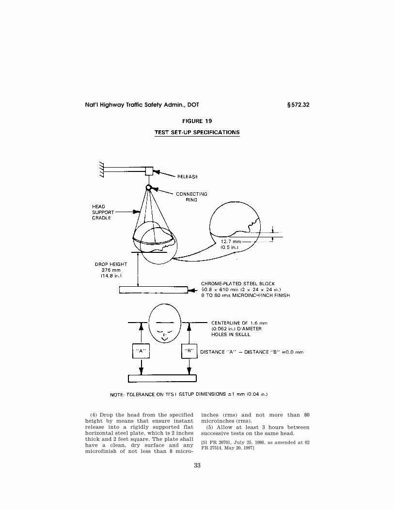
(b) When the head (Drawing number 78051–61X, titled ‘‘head assembly—com-plete,’’ dated March 28, 1997 (Revision C) with six axis neck transducer struc-tural replacement (Drawing number 78051–383X, Revision P, titled ‘‘Neck Transducer Structural Replacement,’’ dated November 1, 1995) is dropped from a height of 14.8 inches in accordance with paragraph (c) of this section, the peak resultant accelerations at the lo-cation of the accelerometers mounted in the head in accordance with § 572.36(c) shall not be less than 225g, and not more than 275g. The accelera-tion/time curve for the test shall be unimodal to the extent that oscilla-tions occurring after the main accel-eration pulse are less than ten percent (zero to peak) of the main pulse. The lateral acceleration vector shall not exceed 15g (zero to peak).
(c) Test procedure. (1) Soak the head assembly in a test environment at any temperature between 66 degrees F to 78 degrees F and at a relative humidity from 10% to 70% for a period of at least four hours prior to its application in a test.
(2) Clean the head’s skin surface and the surface of the impact plate with 1,1,1 Trichlorethane or equivalent.
(3) Suspend the head, as shown in Figure 19, so that the lowest point on the forehead is 0.5 inches below the lowest point on the dummy’s nose when the midsagittal plane is vertical.
VerDate Sep<11>2014 10:23 Mar 06, 2017 Jkt 238231 PO 00000 Frm 00042 Fmt 8010 Sfmt 8010 Y:\SGML\238231.XXX 238231jsta
llwor
th o
n D
SK
7TP
TV
N1P
RO
D w
ith C
FR
33
Nat’l Highway Traffic Safety Admin., DOT § 572.32
(4) Drop the head from the specified height by means that ensure instant release into a rigidly supported flat horizontal steel plate, which is 2 inches thick and 2 feet square. The plate shall have a clean, dry surface and any microfinish of not less than 8 micro-
inches (rms) and not more than 80 microinches (rms).
(5) Allow at least 3 hours between successive tests on the same head.
[51 FR 26701, July 25, 1986, as amended at 62 FR 27514, May 20, 1997]
VerDate Sep<11>2014 10:23 Mar 06, 2017 Jkt 238231 PO 00000 Frm 00043 Fmt 8010 Sfmt 8010 Y:\SGML\238231.XXX 238231 EC
01A
U91
.162
</G
PH
>
jsta
llwor
th o
n D
SK
7TP
TV
N1P
RO
D w
ith C
FR

34
49 CFR Ch. V (10–1–16 Edition) § 572.33
§ 572.33 Neck. (a) The neck consists of the assembly
shown in drawing 78051–90, revision A and conforms to each of the drawings subtended therein.
(b) When the head and neck assembly (consisting of the parts 78051–61X, revi-sion C; –90, revision A; –84; –94; –98; –104, revision F; –303, revision E; –305; –306; –307, revision X) which has a six axis neck transducer (Drawing number C– 1709, Revision D, titled ‘‘Neck trans-ducer,’’ dated February 1, 1993.) in-stalled in conformance with § 572.36(d), is tested in accordance with paragraph (c) of this section, it shall have the fol-lowing characteristics:
(1) Flexion. (i) Plane D, referenced in Figure 20, shall rotate between 64 de-grees and 78 degrees, which shall occur between 57 milliseconds (ms) and 64 ms from time zero. In first rebound, the rotation of Plane D shall cross 0 de-grees between 113 ms and 128 ms.
(ii) The moment measured by the six axis neck transducer (drawing C–1709, revision D) about the occipital condyles, referenced in Figure 20, shall be calculated by the following formula: Moment (lbs-ft) = My¥0.058 × Fx, where My is the moment measured in lbs-ft by the ‘‘Y’’ axis moment sensor of the six axis neck transducer and Fx is the force measured in lbs by the ‘‘X’’
axis force sensor (Channel Class 600) of the six axis neck transducer. The mo-ment shall have a maximum value be-tween 65 lbs-ft and 80 lbs-ft occurring between 47ms and 58 ms, and the posi-tive moment shall decay for the first time to 0 lb-ft between 97 ms and 107 ms.
(2) Extension. (i) Plane D, referenced in Figure 21, shall rotate between 81 de-grees and 106 degrees, which shall occur between 72 ms and 82 ms from time zero. In first rebound, rotation of Plane D shall cross 0 degrees between 147 ms and 174 ms.
(ii) The moment measured by the six axis neck transducer (drawing C–1709, revision D) about the occipital condyles, referenced in Figure 21, shall be calculated by the following formula: Moment (lbs-ft) = My¥0.058 × Fx, where My is the moment measured in lbs-ft by the ‘‘Y’’ axis moment sensor of the six axis neck transducer and Fx is the force measured in lbs by the ‘‘X’’ axis force sensor (Channel Class 600) of the six axis neck transducer. The mo-ment shall have a maximum value be-tween—39 lbs-ft and –59 lbs-ft, occur-ring between 65 ms and 79 ms, and the negative moment shall decay for the first time to 0 lb-ft between 120 ms and 148 ms.
VerDate Sep<11>2014 10:23 Mar 06, 2017 Jkt 238231 PO 00000 Frm 00044 Fmt 8010 Sfmt 8010 Y:\SGML\238231.XXX 238231jsta
llwor
th o
n D
SK
7TP
TV
N1P
RO
D w
ith C
FR

35
Nat’l Highway Traffic Safety Admin., DOT § 572.33
VerDate Sep<11>2014 10:23 Mar 06, 2017 Jkt 238231 PO 00000 Frm 00045 Fmt 8010 Sfmt 8006 Y:\SGML\238231.XXX 238231 ER
20M
Y97
.000
</G
PH
>
jsta
llwor
th o
n D
SK
7TP
TV
N1P
RO
D w
ith C
FR

36
49 CFR Ch. V (10–1–16 Edition) § 572.33
(c) Test procedure. (1) Soak the test material in a test environment at any temperature between 69 degrees F to 72 degrees F and at a relative humidity from 10% to 70% for a period of at least four hours prior to its application in a test.
(2) Torque the jamnut (78051–64) on the neck cable (78051–301, revision E) to 1.0 lbs-ft ±.2 lbs-ft.
(3) Mount the head-neck assembly, defined in paragraph (b) of this section, on a rigid pendulum as shown in Figure 22 so that the head’s midsagittal plane is vertical and coincides with the plane of motion of the pendulum’s longitu-dinal axis.
VerDate Sep<11>2014 10:23 Mar 06, 2017 Jkt 238231 PO 00000 Frm 00046 Fmt 8010 Sfmt 8010 Y:\SGML\238231.XXX 238231 ER
20M
Y97
.001
</G
PH
>
jsta
llwor
th o
n D
SK
7TP
TV
N1P
RO
D w
ith C
FR

37
Nat’l Highway Traffic Safety Admin., DOT § 572.33
(4) Release the pendulum and allow it to fall freely from a height such that the tangential velocity at the pen-dulum accelerometer centerline at the instance of contact with the honey-comb is 23.0 ft/sec ±0.4 ft/sec. for flexion testing and 19.9 ft/sec. ±0.4 ft/sec. for ex-tension testing. The pendulum decel-eration vs. time pulse for flexion test-ing shall conform to the characteris-tics shown in Table A and the decaying
deceleration-time curve shall first cross 5g between 34 ms and 42 ms. The pendulum deceleration vs. time pulse for extension testing shall conform to the characteristics shown in Table B and the decaying deceleration-time curve shall cross 5g between 38 ms and 46 ms.
VerDate Sep<11>2014 10:23 Mar 06, 2017 Jkt 238231 PO 00000 Frm 00047 Fmt 8010 Sfmt 8010 Y:\SGML\238231.XXX 238231 ER
02JN
11.0
11<
/GP
H>
jsta
llwor
th o
n D
SK
7TP
TV
N1P
RO
D w
ith C
FR

38
49 CFR Ch. V (10–1–16 Edition) § 572.34
TABLE A—FLEXION PENDULUM DECELERATION VS. TIME PULSE
Time (ms) Flexion de-celeration level (g)
10 ..................................................................... 22.50–27.50 20 ..................................................................... 17.60–22.60 30 ..................................................................... 12.50–18.50 Any other time above 30 ms ........................... 29 maximum.
TABLE B—EXTENSION PENDULUM DECELERATION VS. TIME PULSE
Time (ms) Extension de-
celeration level (g)
10 ..................................................................... 17.20–21.20 20 ..................................................................... 14.00–19.00 30 ..................................................................... 11.00–16.00 Any other time above 30 ms ........................... 22 maximum.
(5) Allow the neck to flex without im-pact of the head or neck with any ob-ject during the test.
[51 FR 26701, July 25, 1986, as amended at 53 FR 8765, Mar. 17, 1988; 62 FR 27514, May 20, 1997; 76 FR 31864, June 2, 2011]
§ 572.34 Thorax. (a) The thorax consists of the upper
torso assembly in drawing 78051–89, re-
vision K and shall conform to each of the drawings subtended therein.
(b) When impacted by a test probe conforming to § 572.36(a) at 22 fps ±0.40 fps in accordance with paragraph (c) of this section, the thorax of a complete dummy assembly (78051–218, revision U, without shoes, shall resist with a force of 1242.5 pounds ±82.5 pounds measured by the test probe and shall have a ster-num displacement measured relative to spine of 2.68 inches ±0.18 inches. The in-ternal hysteresis in each impact shall be more than 69% but less than 85%. The force measured is the product of pendulum mass and deceleration.
(c) Test procedure. (1) Soak the test dummy in an environment with a rel-ative humidity from 10% to 70% until the temperature of the ribs of the test dummy have stabilized at a tempera-ture between 69 degrees F and 72 de-grees F.
(2) Seat the dummy without back and arm supports on a surface as shown in Figure 23, and set the angle of the pel-vic bone at 13 degrees plus or minus 2 degrees, using the procedure described in S11.4.3.2 of Standard No. 208 (§ 571.208 of this chapter).
VerDate Sep<11>2014 10:23 Mar 06, 2017 Jkt 238231 PO 00000 Frm 00048 Fmt 8010 Sfmt 8010 Y:\SGML\238231.XXX 238231jsta
llwor
th o
n D
SK
7TP
TV
N1P
RO
D w
ith C
FR

39
Nat’l Highway Traffic Safety Admin., DOT § 572.34
(3) Place the longitudinal centerline of the test probe so that it is .5 ±.04 in. below the horizontal centerline of the No. 3 Rib (reference drawing number
79051–64, revision A-M) as shown in Fig-ure 23.
VerDate Sep<11>2014 10:23 Mar 06, 2017 Jkt 238231 PO 00000 Frm 00049 Fmt 8010 Sfmt 8010 Y:\SGML\238231.XXX 238231 EC
01A
U91
.166
</G
PH
>
jsta
llwor
th o
n D
SK
7TP
TV
N1P
RO
D w
ith C
FR

40
49 CFR Ch. V (10–1–16 Edition) § 572.35
(4) Align the test probe specified in § 572.36(a) so that at impact its longitu-dinal centerline coincides within .5 de-gree of a horizontal line in the dum-my’s midsagittal plane.
(5) Impact the thorax with the test probe so that the longitudinal center-line of the test probe falls within 2 de-grees of a horizontal line in the dummy midsagittal plane at the moment of impact.
(6) Guide the probe during impact so that it moves with no significant lat-eral, vertical, or rotational movement.
(7) Measure the horizontal deflection of the sternum relative to the thoracic spine along the line established by the longitudinal centerline of the probe at the moment of impact, using a poten-tiometer (ref. drawing 78051–317, revi-sion A) mounted inside the sternum as shown in drawing 78051–89, revision I.
(8) Measure hysteresis by deter-mining the ratio of the area between the loading and unloading portions of the force deflection curve to the area under the loading portion of the curve.
[51 FR 26701, July 25, 1986, as amended at 53 FR 8765, Mar. 17, 1988; 62 FR 27518, May 20, 1997; 63 FR 53851, Oct. 7, 1998]
§ 572.35 Limbs.
(a) The limbs consist of the following assemblies: leg assemblies 86–5001–001, revision A and –002, revision A, and arm assemblies 78051–123, revision D and –124, revision D, and shall conform to the drawings subtended therein.
(b) Femur impact response. (1) When each knee of the leg assemblies is im-pacted in accordance with paragraph (b)(2) of this section, at 6.9 ft/sec ±0.10 ft/sec by the pendulum defined in § 572.36(b), the peak knee impact force, which is a product of pendulum mass and acceleration, shall have a min-imum value of not less than 1060 pounds and a maximum value of not more than 1300 pounds.
(2) Test procedure. (i) The test mate-rial consists of leg assemblies (86–5001– 001, revision A) left and (–002, revision A) right with upper leg assemblies (78051–46) left and (78051–47) right re-moved. The load cell simulator (78051– 319, revision A) is used to secure the knee cap assemblies (79051–16, revision B) as shown in Figure 24.
(ii) Soak the test material in a test environment at any temperature be-tween 66 degrees F to 78 degrees F and at a relative humidity from 10% to 70% for a period of at least four hours prior to its application in a test.
(iii) Mount the test material with the leg assembly secured through the load cell simulator to a rigid surface as shown in Figure 24. No contact is per-mitted between the foot and any other exterior surfaces.
(iv) Place the longitudinal centerline of the test probe so that at contact with the knee it is collinear within 2 degrees with the longitudinal center-line of the femur load cell simulator.
(v) Guide the pendulum so that there is no significant lateral, vertical or ro-tational movement at time zero.
(vi) Impact the knee with the test probe so that the longitudinal center-line of the test probe at the instant of impact falls within .5 degrees of a hori-zontal line parallel to the femur load cell simulator at time zero.
(vii) Time zero is defined as the time of contact between the test probe and the knee.
(c) Hip joint-femur flexion. (1) When each femur is rotated in the flexion di-rection in accordance with paragraph (c)(2) of this section, the femur torque at 30 deg. rotation from its initial hori-zontal orientation will not be more than 70 ft-lbf, and at 150 ft-lbf of torque will not be less than 40 deg. or more than 50 deg.
(2) Test procedure. (i) The test mate-rial consists of the assembled dummy, part No. 78051–218 (revision S) except that (1) leg assemblies (86–5001–001 and 002) are separated from the dummy by removing the 3/8–16 Socket Head Cap Screw (SHCS) (78051–99) but retaining the structural assembly of the upper legs (78051–43 and –44), (2) the abdom-inal insert (78051–52) is removed and (3) the instrument cover plate (78051–13) in the pelvic bone is replaced by a rigid pelvic bone stabilizer insert (Figure 25a) and firmly secured.
(ii) Seat the dummy on a rigid seat fixture (Figure 25) and firmly secure it to the seat back by bolting the sta-bilizer insert and the rigid support de-vice (Figure 25b) to the seat back of the test fixture (Figures 26 and 27) while
VerDate Sep<11>2014 10:23 Mar 06, 2017 Jkt 238231 PO 00000 Frm 00050 Fmt 8010 Sfmt 8010 Y:\SGML\238231.XXX 238231jsta
llwor
th o
n D
SK
7TP
TV
N1P
RO
D w
ith C
FR

41
Nat’l Highway Traffic Safety Admin., DOT § 572.35
maintaining the pelvis (78051–58) ‘‘B’’ plane horizontal.
(iii) Insert a lever arm into the femur shaft opening of the upper leg struc-ture assembly (78051–43/44) and firmly secure it using the 3/8–16 socket head cap screws.
(iv) Lift the lever arm parallel to the midsagittal plane at a rotation rate of 5 to 10 deg. per second while maintain-
ing the 1⁄2 in. shoulder bolt longitudinal centerline horizontal throughout the range of motion until the 150 ft-lbf torque level is reached. Record the torque and angle of rotation of the femur.
(v) Operating environment and tem-perature are the same as specified in paragraph (b)(2)(ii) of this section.
VerDate Sep<11>2014 10:23 Mar 06, 2017 Jkt 238231 PO 00000 Frm 00051 Fmt 8010 Sfmt 8006 Y:\SGML\238231.XXX 238231 EC
01A
U91
.167
</G
PH
>
jsta
llwor
th o
n D
SK
7TP
TV
N1P
RO
D w
ith C
FR

42
49 CFR Ch. V (10–1–16 Edition) § 572.35
VerDate Sep<11>2014 10:23 Mar 06, 2017 Jkt 238231 PO 00000 Frm 00052 Fmt 8010 Sfmt 8006 Y:\SGML\238231.XXX 238231 ER
26D
E96
.004
</G
PH
>
jsta
llwor
th o
n D
SK
7TP
TV
N1P
RO
D w
ith C
FR

43
Nat’l Highway Traffic Safety Admin., DOT § 572.35
VerDate Sep<11>2014 10:23 Mar 06, 2017 Jkt 238231 PO 00000 Frm 00053 Fmt 8010 Sfmt 8006 Y:\SGML\238231.XXX 238231 ER
26D
E96
.005
</G
PH
>E
R26
DE
96.0
06<
/GP
H>
jsta
llwor
th o
n D
SK
7TP
TV
N1P
RO
D w
ith C
FR

44
49 CFR Ch. V (10–1–16 Edition) § 572.35
VerDate Sep<11>2014 10:23 Mar 06, 2017 Jkt 238231 PO 00000 Frm 00054 Fmt 8010 Sfmt 8006 Y:\SGML\238231.XXX 238231 ER
26D
E96
.007
</G
PH
>
jsta
llwor
th o
n D
SK
7TP
TV
N1P
RO
D w
ith C
FR

45
Nat’l Highway Traffic Safety Admin., DOT § 572.36
[51 FR 26701, July 25, 1986, as amended at 53 FR 8765, Mar. 17, 1988; 61 FR 67955, Dec. 26, 1997; 63 FR 5748, Feb. 4, 1998]
§ 572.36 Test conditions and instru-mentation.
(a) The test probe used for thoracic impact tests is a 6 inch diameter cyl-inder that weighs 51.5 pounds including instrumentation. Its impacting end has a flat right angle face that is rigid and has an edge radius of 0.5 inches. The test probe has an accelerometer mounted on the end opposite from im-pact with its sensitive axis colinear to
the longitudinal centerline of the cyl-inder.
(b) Test probe used for the knee im-pact tests is a 3 inch diameter cylinder that weights 11 pounds including in-strumentation. Its impacting end has a flat right angle face that is rigid and has an edge radius of 0.02 inches. The test probe has an accelerometer mounted on the end opposite from im-pact with its sensitive axis colinear to
VerDate Sep<11>2014 10:23 Mar 06, 2017 Jkt 238231 PO 00000 Frm 00055 Fmt 8010 Sfmt 8010 Y:\SGML\238231.XXX 238231 ER
26D
E96
.008
</G
PH
>
jsta
llwor
th o
n D
SK
7TP
TV
N1P
RO
D w
ith C
FR

46
49 CFR Ch. V (10–1–16 Edition) § 572.40
the longitudinal centerline of the cyl-inder.
(c) Head accelerometers shall have dimensions and response characteris-tics specified in drawing 78051–136, revi-sion A, or its equivalent, and the loca-tion of their seismic mass as mounted in the skull are shown in drawing C– 1709, revision D.
(d) The six axis neck transducer shall have the dimensions, response charac-teristics, and sensitive axis locations specified in drawing C–1709, revision D and be mounted for testing as shown in Figures 20 and 21 of § 572.33, and in the assembly drawing 78051–218, revision T.
(e) The chest accelerometers shall have the dimensions, response charac-teristics, and sensitive mass locations specified in drawing 78051–136, revision A or its equivalent and be mounted as shown with adaptor assembly 78051–116, revision D for assembly into 78051–218, revision T.
(f) The chest deflection transducer shall have the dimensions and response characteristics specified in drawing 78051–342, revision A or its equivalent and be mounted in the chest deflection transducer assembly 78051–317, revision A for assembly into 78051–218, revision T.
(g) The thorax and knee impactor accelerometers shall have the dimen-sions and characteristics of Endevco Model 7231c or equivalent. Each accel-erometer shall be mounted with its sensitive axis colinear with the pen-dulum’s longitudinal centerline.
(h) The femur load cell shall have the dimensions, response characteristics, and sensitive axis locations specified in drawing 78051–265 or its equivalent and be mounted in assemblies 78051–46 and –47 for assembly into 78051–218, revision T.
(i) The outputs of acceleration and force-sensing devices installed in the dummy and in the test apparatus speci-fied by this part are recorded in indi-vidual data channels that conform to requirements of Society of Automotive Engineers (SAE) Recommended Prac-tice J211 Mar95, Instrumentation for Impact Tests, Parts 1 and 2. SAE J211 Mar95 sets forth the following channel classes:
(1) Head acceleration—Class 1000 (2) Neck forces—Class 1000
(3) Neck moments—Class 600 (4) Neck pendulum acceleration—
Class 60 (5) Thorax and thorax pendulum ac-
celeration—Class 180 (6) Thorax deflection—Class 180 (7) Knee pendulum acceleration—
Class 600 (8) Femur force—Class 600 (j) Coordinate signs for instrumenta-
tion polarity conform to the sign con-vention shown in the document incor-porated by § 572.31(a)(5).
(k) The mountings for sensing de-vices shall have no resonance fre-quency within range of 3 times the fre-quency range of the applicable channel class.
(l) Limb joints are set at lg, barely restraining the weight of the limb when it is extended horizontally. The force required to move a limb segment shall not exceed 2g throughout the range of limb motion.
(m) Performance tests of the same component, segment, assembly, or fully assembled dummy are separated in time by period of not less than 30 minutes unless otherwise noted.
(n) Surfaces of dummy components are not painted except as specified in this part or in drawings subtended by this part.
[51 FR 26701, July 25, 1986, as amended at 53 FR 8765, Mar. 17, 1988; 62 FR 27518, May 20, 1997; 63 FR 45965, Aug. 28, 1998]
Subpart F—Side Impact Dummy 50th Percentile Male
SOURCE: 55 FR 45766, Oct. 30, 1990, unless otherwise noted.
§ 572.40 Incorporated materials. (a) The drawings, specifications,
manual, and computer program re-ferred to in this regulation that are not set forth in full are hereby incor-porated in this part by reference. These materials are thereby made part of this regulation. The Director of the Federal Register has approved the materials in-corporated by reference. For materials subject to change, only the specific version approved by the Director of the Federal Register and specified in the regulation are incorporated. A notice of any change will be published in the FEDERAL REGISTER. As a convenience
VerDate Sep<11>2014 10:23 Mar 06, 2017 Jkt 238231 PO 00000 Frm 00056 Fmt 8010 Sfmt 8010 Y:\SGML\238231.XXX 238231jsta
llwor
th o
n D
SK
7TP
TV
N1P
RO
D w
ith C
FR

47
Nat’l Highway Traffic Safety Admin., DOT § 572.42
to the reader, the materials incor-porated by reference are listed in the Finding Aids Table found at the end of this volume of the Code of Federal Reg-ulations.
(b) The materials incorporated in this part by reference are available for examination in the general reference section of Docket 79–04, Docket Sec-tion, National Highway Traffic Safety Administration, room 5109, 400 Seventh St., S.W., Washington, D.C., 20590, tele-phone (202) 366–4949. Copies may be ob-tained from Reprographic Tech-nologies, 9000 Virginia Manor Rd., Suite 210, Beltsville, MD, 20705, Tele-phone (301) 419–5070, Fax (301) 419–5069.
[55 FR 45766, Oct. 30, 1990, as amended at 63 FR 16140, Apr. 2, 1998]
§ 572.41 General description.
(a) The dummy consists of compo-nent parts and component assemblies (SA-SID-M001, revision C, dated Sep-tember 12, 1996, and SA-SID-M001A, re-vision B, dated September 12, 1996), which are described in approximately 250 drawings and specifications that are set forth in § 572.5(a) of this chapter with the following changes and addi-tions which are described in approxi-mately 85 drawings and specifications (incorporated by reference; see § 572.40):
(1) The head assembly consists of the assembly specified in subpart B (§ 572.6(a)) and conforms to each of the drawings subtended under drawing SA 150 M010 and drawings specified in SA- SID-M010, dated August 13, 1987.
(2) The neck assembly consists of the assembly specified in subpart B (§ 572.7(a)) and conforms to each of the drawings subtended under drawing SA 150 M020 and drawings shown in SA- SID-M010, dated August 13, 1987.
(3) The thorax assembly consists of the assembly shown as number SID–053 and conforms to each applicable draw-ing subtended by number SA-SID-M030 revision A, dated May 18, 1994.
(4) The lumbar spine consists of the assembly specified in subpart B (§ 572.9(a)) and conforms to drawing SA 150 M050 and drawings subtended by SA-SID-M050 revision B, dated Sep-tember 12, 1996, including the addition of Lumbar Spacers-Lower SID-SM-001 and Lumbar Spacers-Upper SID-SM-002
(both dated May 12, 1994), and Washer 78051–243.
(5) The abdomen and pelvis consist of the assembly specified in subpart B of this part (§ 572.9) and conform to the drawings subtended by SA 150 M060, the drawings subtended by SA-SID-M060 re-vision A, dated May 18, 1994, and the drawings subtended by SA-SID-087 sheet 1 revision H, dated May 18, 1994, and SA-SID-087 sheet 2 revision H.
(6) The lower limbs consist of the as-semblies specified in subpart B (§ 572.10) shown as SA 150 M080 and SA 150 M081 in Figure 1 and SA-SID-M080 and SA- SID-M081, both dated August 13, 1987, and conform to the drawings subtended by those numbers.
(b) The structural properties of the dummy are such that the dummy con-forms to the requirements of this sub-part in every respect both before and after being used in vehicle tests speci-fied in Standard No 214 § 571.214 of this chapter.
(c) Disassembly, inspection, and as-sembly procedures; external dimen-sions and weight; and a dummy draw-ing list are set forth in the Side Impact Dummy (SID) User’s Manual, dated May 1994 except for pages 7, 20 and 23, and appendix A (consisting of replace-ment pages 7, 20 and 23) dated January 20, 1998 (incorporated by reference; see § 572.40).
[55 FR 45766, Oct. 30, 1990, as amended at 59 FR 52091, Oct. 14, 1994; 63 FR 16140, Apr. 2, 1998]
§ 572.42 Thorax.
(a) When the thorax of a completely assembled dummy (SA-SID-M001A revi-sion A, dated May 18, 1994, incorporated by reference; see § 572.40), appropriately assembled for right or left side impact, is impacted by a test probe conforming to § 572.44(a) at 14 fps in accordance with paragraph (b) of this section, the peak accelerations at the location of the accelerometers mounted on the thorax in accordance with § 572.44(b) shall be:
(1) For the accelerometer at the top of the Rib Bar on the struck side (LUR or RUR) not less than 37 g’s and not more than 46 g’s.
(2) For the accelerometer at the bot-tom of the Rib Bar on the struck side
VerDate Sep<11>2014 10:23 Mar 06, 2017 Jkt 238231 PO 00000 Frm 00057 Fmt 8010 Sfmt 8010 Y:\SGML\238231.XXX 238231jsta
llwor
th o
n D
SK
7TP
TV
N1P
RO
D w
ith C
FR

48
49 CFR Ch. V (10–1–16 Edition) § 572.43
(LLR or RLR) not less than 37 g’s and not more than 46 g’s.
(3) For the lower thoracic spine (T12) not less than 15 g’s and not more than 22 g’s.
(b) Test Procedure. (1) Adjust the dummy legs as specified in § 572.44(f). Seat the dummy on a seating surface as specified in § 572.44(h) with the limbs extended horizontally forward.
(2) Place the longitudinal centerline of the test probe at the lateral side of the chest at the intersection of the centerlines of the third rib and the Rib Bar on the desired side of impact. This is the left side if the dummy is to be used on the driver’s side of the vehicle and the right side if the dummy is to be used on the passenger side of the ve-hicle. The probe’s centerline is perpen-dicular to thorax’s midsagittal plane.
(3) Align the test probe so that its longitudinal centerline coincides with the line formed by the intersection of the transverse and frontal planes per-pendicular to the chest’s midsagittal plane passing through the designated impact point.
(4) Position the dummy as specified in § 572.44(h), so that the thorax’s midsagittal plane and tangential plane to the Hinge Mounting Block (Drawing SID–034) are vertical.
(5) Impact the thorax with the test probe so that at the moment of impact at the designated impact point, the probe’s longitudinal centerline falls within 2 degrees of a horizontal line perpendicular to the dummy’s midsagittal plane and passing through the designated impact point.
(6) Guide the probe during impact so that it moves with no significant lat-eral, vertical or rotational movement.
(7) Allow a time period of at least 20 minutes between successive tests of the chest.
[59 FR 52091, Oct. 14, 1994, as amended at 59 FR 52091, Oct. 14, 1994]
§ 572.43 Lumbar spine and pelvis. (a) When the pelvis of a fully assem-
bled dummy (SA-SID-M001A revision B, dated September 12, 1996, (incorporated by reference; see § 572.40) is impacted laterally by a test probe conforming to § 572.44(a) at 14 fps in accordance with paragraph (b) of this section, the peak acceleration at the location of the ac-
celerometer mounted in the pelvis cav-ity in accordance with § 572.44(c) shall be not less than 40g and not more than 60g. The acceleration-time curve for the test shall be unimodal and shall lie at or above the + 20g level for an inter-val not less than 3 milliseconds and not more than 7 milliseconds.
(b) Test Procedure. (1) Adjust the dummy legs as specified in § 572.44(f). Seat the dummy on a seating surface as specified in § 572.44(h) with the limbs extended horizontally forward.
(2) Place the longitudinal centerline of the test probe at the lateral side of the pelvis at a point 3.9 inches vertical from the seating surface and 4.8 inches ventral to a transverse vertical plane which is tangent to the back of the dummy’s buttocks.
(3) Align the test probe so that at im-pact its longitudinal centerline coin-cides with the line formed by intersec-tion of the horizontal and vertical planes perpendicular to the midsagittal plane passing through the designated impact point.
(4) Adjust the dummy so that its midsagittal plane is vertical and the rear surfaces of the thorax and but-tocks are tangent to a transverse vertical plane.
(5) Impact the pelvis with the test probe so that at the moment of impact the probe’s longitudinal centerline falls within 2 degrees of the line speci-fied in paragraph (b)(3) of this section.
(6) Guide the test probe during im-pact so that it moves with no signifi-cant lateral, vertical or rotational movement.
(7) Allow a time period of at least 2 hours between successive tests of the pelvis.
[55 FR 45766, Oct. 30, 1990, as amended at 59 FR 52091, Oct. 14, 1994; 63 FR 16140, Apr. 2, 1998]
§ 572.44 Instrumentation and test con-ditions.
(a) The test probe used for lateral thoracic and pelvis impact tests is a 6 inch diameter cylinder that weighs 51.5 pounds including instrumentation. Its impacting end has a flat right angle face that is rigid and has an edge ra-dius of 0.5 inches.
(b) Three accelerometers are mount-ed in the thorax for measurement of
VerDate Sep<11>2014 10:23 Mar 06, 2017 Jkt 238231 PO 00000 Frm 00058 Fmt 8010 Sfmt 8010 Y:\SGML\238231.XXX 238231jsta
llwor
th o
n D
SK
7TP
TV
N1P
RO
D w
ith C
FR

49
Nat’l Highway Traffic Safety Admin., DOT § 572.44
lateral accelerations with each accelerometer’s sensitive axis aligned to be closely perpendicular to the thorax’s midsagittal plane. The accelerometers are mounted in the fol-lowing locations:
(1) One accelerometer is mounted on the thorax to lumbar adaptor (SID–005 revision F, dated May 18, 1994, incor-porated by reference; see § 572.40) with seismic mass center located 0.5 inches toward the impact side, 0.1 inches up-ward and 1.86 inches rearward from the reference point shown in Figure 30 in appendix A to subpart F of part 572. Maximum permissible variation of the seismic location must not exceed 0.2 inches spherical radius.
(2) Two accelerometers are mounted, one on the top and the other at the bot-tom part of the Rib Bar (SID–024) on the struck side. Their seismic mass centers are at any distance up to .4 inches from a point on the Rib Bar sur-face located on its longitudinal center line .75 inches from the top for the top accelerometer and .75 inches from the bottom, for the bottom accelerometer.
(c) One accelerometer is mounted in the pelvis for measurement of the lat-eral acceleration with its sensitive axis perpendicular to the pelvic midsagittal plane. The accelerometer is mounted on the rear wall of the instrumentation cavity of the pelvis (SID–087 revision H, dated May 18, 1994, incorporated by ref-erence; see § 572.40). The accelerometer’s seismic mass with re-spect to the mounting bolt center line is 0.9 inches up, 0.7 inches to the left for left side impact and 0.03 inches to the left for right side impact, and 0.5 inches rearward from the rear wall mounting surface as shown in Figure 31 in appendix A to subpart F of part 572. Maximum permissible variation of the seismic location must not exceed 0.2 inches spherical radius.
(d) Instrumentation and sensors used must conform to the SAE J–211 (1980) recommended practice requirements (incorporated by reference; see § 572.40). The outputs of the accelerometers in-stalled in the dummy are then proc-essed with the software for the Finite Impulse Response (FIR) filter (FIR 100 software). The FORTRAN program for this FIR 100 software (FIR100 Filter Program, Version 1.0, July 16, 1990) is
incorporated by reference in this part (see § 572.40). The data are processed in the following manner:
(1) Analog data recorded in accord-ance with SAE J–211 (1980) rec-ommended practice channel class 1000 specification.
(2) Filter the data with a 300 Hz, SAE Class 180 filter;
(3) Subsample the data to a 1600 Hz sampling rate;
(4) Remove the bias from the subsam-pled data, and
(5) Filter the data with the FIR100 Filter Program (Version 1.0, July 16, 1990), which has the following charac-teristics—
(i) Passband frequency, 100 Hz. (ii) Stopband frequency, 189 Hz. (iii) Stopband gain, ¥50 db. (iv) Passband ripple, 0.0225 db. (e) The mountings for the spine, rib
and pelvis accelerometers shall have no resonance frequency within a range of 3 times the frequency range of the appli-cable channel class.
(f) Limb joints of the test dummy are set at the force between 1–2 g’s, which just supports the limbs’ weight when the limbs are extended horizontally forward. The force required to move a limb segment does not exceed 2 g’s throughout the range of limb motion.
(g) Performance tests are conducted at any temperature from 66 °F to 78 °F and at any relative humidity from 10 percent to 70 percent after exposure of the dummy to these conditions for a period of not less than 4 hours.
(h) For the performance of tests spec-ified in §§ 572.42 and 572.43, the dummy is positioned as follows:
(1) The dummy is placed on a flat, rigid, clean, dry, horizontal smooth aluminum surface whose length and width dimensions are not less than 16 inches, so that the dummy’s midsagittal plane is vertical and cen-tered on the test surface. The dummy’s torso is positioned to meet the require-ments of § 572.42 and § 572.43. The seat-ing surface is without the back support and the test dummy is positioned so that the dummy’s midsagittal plane is vertical and centered on the seat sur-face.
(2) The legs are positioned so that their centerlines are in planes parallel to the midsagittal plane.
VerDate Sep<11>2014 10:23 Mar 06, 2017 Jkt 238231 PO 00000 Frm 00059 Fmt 8010 Sfmt 8010 Y:\SGML\238231.XXX 238231jsta
llwor
th o
n D
SK
7TP
TV
N1P
RO
D w
ith C
FR

50
49 CFR Ch. V (10–1–16 Edition) § 572.44
(3) Performance pre-tests of the as-sembled dummy are separated in time by a period of not less than 20 minutes unless otherwise specified.
(4) Surfaces of the dummy compo-nents are not painted except as speci-
fied in this part or in drawings sub-tended by this part.
[55 FR 45766, Oct. 30, 1990, as amended at 56 FR 47011, Sept. 17, 1991; 59 FR 52091, Oct. 14, 1994]
VerDate Sep<11>2014 10:23 Mar 06, 2017 Jkt 238231 PO 00000 Frm 00060 Fmt 8010 Sfmt 8010 Y:\SGML\238231.XXX 238231jsta
llwor
th o
n D
SK
7TP
TV
N1P
RO
D w
ith C
FR

51
Nat’l Highway Traffic Safety Admin., DOT Pt. 572, Subpt. F, App. A
APPENDIX A TO SUBPART F OF PART 572—FIGURES
VerDate Sep<11>2014 10:23 Mar 06, 2017 Jkt 238231 PO 00000 Frm 00061 Fmt 8010 Sfmt 8006 Y:\SGML\238231.XXX 238231 EC
01A
U91
.168
</G
PH
>
jsta
llwor
th o
n D
SK
7TP
TV
N1P
RO
D w
ith C
FR

52
49 CFR Ch. V (10–1–16 Edition) Pt. 572, Subpt. F, App. A
[59 FR 52092, Oct. 14, 1994]
VerDate Sep<11>2014 10:23 Mar 06, 2017 Jkt 238231 PO 00000 Frm 00062 Fmt 8010 Sfmt 8006 Y:\SGML\238231.XXX 238231 ER
14O
C94
.001
</G
PH
>
jsta
llwor
th o
n D
SK
7TP
TV
N1P
RO
D w
ith C
FR

53
Nat’l Highway Traffic Safety Admin., DOT § 572.72
Subparts G–H [Reserved]
Subpart I—6-Year-Old Child
SOURCE: 56 FR 57836, Nov. 14, 1991, unless otherwise noted.
§ 572.70 Incorporation by reference. (a) The drawings and specifications
referred to in §§ 572.71(a) and 572.71(b) are hereby incorporated in subpart I by reference. These materials are thereby made part of this regulation. The Di-rector of the Federal Register approved the materials incorporated by ref-erence in accordance with 5 U.S.C. 552(a) and 1 CFR part 51. Copies of the materials may be inspected at NHTSA’s Docket Section, 400 Seventh Street, SW., room 5109, Washington, DC, or at the National Archives and Records Administration (NARA). For information on the availability of this material at NARA, call 202–741–6030, or go to: http://www.archives.gov/ federallregister/ codeloflfederallregulations/ ibrllocations.html.
(b) The incorporated material is available as follows:
(1) Drawing number SA 106 C001 sheets 1 through 18, and the drawings listed in the parts lists described on sheets 8 through 17, are available from
Reprographic Technologies, 9000 Vir-ginia Manor Rd., Beltsville, MD 20705, Telephone (301) 210–5600, Fax (301) 210– 5607.
(2) A User’s Manual entitled, ‘‘Six- Year-Old Size Child Test Dummy SA106C,’’ October 28, 1991, is available from Reprographic Technologies at the address in paragraph (b)(1) of this sec-tion.
(3) SAE Recommended Practice J211, Instrumentation for Impact Test, June 1988, is available from the Society of Automotive Engineers, Inc., 400 Com-monwealth Drive, Warrendale, PA 15096–0001.
[56 FR 57836, Nov. 14, 1991, as amended at 62 FR 44226, Aug. 20, 1997]
§ 572.71 General description. (a) The representative 6-year-old
dummy consists of a drawings and specifications package that contains the following materials:
(1) Technical drawings, specifica-tions, and the parts list package shown in SA 106C 001, sheets 1 through 18, re-released July 11, 1997;
(2) A user’s manual entitled, ‘‘Six- Year-Old Size Child Test Dummy SA106C,’’ October 28, 1991.
(b) The dummy is made up of the component assemblies set out in Table A:
TABLE A
Assembly drawing No. Drawing title Listed on drawing No. Revision
SA 106C 010 ............................... Head Assembly .......................... SA 106C 001, sheet 8 ............... A SA 106C 020 ............................... Neck Assembly .......................... SA 106C 001, sheet 9 ............... A SA 106C 030 ............................... Thorax Assembly ....................... SA 106C 001, sheet 10 ............. C SA 106C 030 ............................... Thorax Assembly ....................... SA 106C 001, sheet 11 ............. D SA 106C 041 ............................... Arm Assembly (right) ................. SA 106C 001, sheet 14 ............. A SA 106C 042 ............................... Arm Assembly (left) .................... SA 106C 001, sheet 15 ............. A SA 106C 050 ............................... Lumbar Spine Assembly ............ SA 106C 001, sheet 12 ............. A SA 106C 060 ............................... Pelvis Assembly ......................... SA 106C 001, sheet 13 ............. A SA 106C 071 ............................... Leg Assembly (right) .................. SA 106C 001, sheet 16 ............. A SA 106C 072 ............................... Leg Assembly (left) .................... SA 106C 001, sheet 17 ............. A
(c) Adjacent segments are joined in a manner such that except for contacts existing under static conditions, there is no contact between metallic ele-ments throughout the range of motion or under simulated crash-impact condi-tions.
(d) The structural properties of the dummy are such that the dummy con-forms to this part in every respect both
before and after its use in any test similar to those specified in Standard 213, Child Restraint Systems.
[56 FR 57836, Nov. 14, 1991, as amended at 62 FR 44226, Aug. 20, 1997]
§ 572.72 Head assembly and test proce-dure.
(a) Head assembly. The head consists of the assembly designated as SA 106
VerDate Sep<11>2014 10:23 Mar 06, 2017 Jkt 238231 PO 00000 Frm 00063 Fmt 8010 Sfmt 8010 Y:\SGML\238231.XXX 238231jsta
llwor
th o
n D
SK
7TP
TV
N1P
RO
D w
ith C
FR

54
49 CFR Ch. V (10–1–16 Edition) § 572.73
010 on drawing No. SA 106C 001, sheet 2, and conforms to each drawing listed on SA 106C 001, sheet 8.
(b) Head assembly impact response re-quirements. When the head is impacted by a test probe conforming to § 572.77(a)(1) at 7 feet per second (fps) according to the test procedure in paragraph (c) of this section, then the resultant head acceleration measured at the location of the accelerometer in-stalled in the headform according to § 577.77(b) is not less than 130g and not more than 160g.
(1) The recorded acceleration-time curve for this test is unimodal at or above the 50g level, and lies at or above that level for an interval not less than 1.0 and not more than 2.0 milliseconds.
(2) The lateral acceleration vector does not exceed 5g.
(c) Head test procedure. The test pro-cedure for the head is as follows:
(1) Seat and orient the dummy on a seating surface having a back support as specified in § 572.78(c), and adjust the joints of the limbs at any setting (be-tween 1g and 2g) which just supports the limbs’ weight when the limbs are extended horizontally and forward.
(2) Adjust the test probe so that its longitudinal center line is—
(i) At the forehead at the point of or-thogonal intersection of the head midsagittal plane and the transverse plane which is perpendicular to the Z axis of the head as shown in Figure 40;
(ii) Located 2.7 ±0.1 inches below the top of the head measured along the Z axis, and;
(iii) Coincides within 2 degrees with the line made by the intersection of the horizontal and midsagittal planes passing through this point.
(3) Impact the head with the test probe so that at the moment of contact the probe’s longitudinal center line falls within 2 degrees of a horizontal line in the dummy’s midsagittal plane.
(4) Guide the test probe during im-pact so that there is no significant lat-eral, vertical, or rotational movement.
(5) Allow at least 60 minutes between successive head tests.
§ 572.73 Neck assembly and test proce-dure.
(a) Neck assembly. The neck consists of the assembly designated as SA 106C
020 on drawing SA 106C 001, sheet 2, and conforms to each drawing listed on SA 106C 001, sheet 9.
(b) Neck assembly impact response re-quirements. When the head-neck assem-bly (SA 106C 010 and SA 106C 020) is tested according to the test procedure in § 572.73(c), the head:
(1) Shall rotate, while translating in the direction of the pendulum preimpact flight, in reference to the pendulum’s longitudinal center line a total of 78 degrees ±6 degrees about the head’s center of gravity; and
(2) Shall rotate to the extent speci-fied in Table B at each indicated point in time, measured from time of impact, with the chordal displacement meas-ured at the head’s center of gravity.
(i) Chordal displacement at time ‘‘T’’ is defined as the straight line distance between the position relative to the pendulum arm of the head’s center of gravity at time ‘‘zero;’’ and the posi-tion relative to the pendulum arm of the head’s center of gravity at time T as illustrated by Figure 3 in § 572.11.
(ii) The peak resultant acceleration recorded at the location of the accelerometers mounted in the headform according to § 572.77(b) shall not exceed 30g.
TABLE B
Rotation (degrees) Time (ms) ±(2 + .08T)
Chordal dis-placement
(inches) ±0.8
0 ......................................... 0 0 30 ....................................... 26 2.7 60 ....................................... 44 4.3 Maximum ........................... 68 5.8 60 ....................................... 101 4.4 30 ....................................... 121 2.4 0 ......................................... 140 0
(3) The pendulum shall not reverse direction until the head’s center of gravity returns to the original ‘‘zero’’ time position relative to the pendulum arm.
(c) Neck test procedure. The test proce-dure for the neck is as follows:
(1) Mount the head and neck assem-bly on a rigid pendulum as specified in § 572.21, Figure 15, so that the head’s midsagittal plane is vertical and coin-cides with the plane of motion of the pendulum’s longitudinal center line. Attach the neck directly to the pen-dulum as shown in § 572.21, Figure 15.
VerDate Sep<11>2014 10:23 Mar 06, 2017 Jkt 238231 PO 00000 Frm 00064 Fmt 8010 Sfmt 8010 Y:\SGML\238231.XXX 238231jsta
llwor
th o
n D
SK
7TP
TV
N1P
RO
D w
ith C
FR

55
Nat’l Highway Traffic Safety Admin., DOT § 572.74
(2) Release the pendulum and allow it to fall freely from a height such that the velocity at impact is 17.00 ±1.0 fps, measured at the center of the acceler-ometer specified in § 572.21, Figure 15.
(3) Decelerate the pendulum to a stop with an acceleration-time pulse de-scribed as follows:
(i) Establish 5g and 20g levels on the a-t curve.
(ii) Establish t1 at the point where the rising a-t curve first crosses the 5g level; t2 at the point where the rising a- t curve first crosses the 20g level; t3 at the point where the decaying a-t curve last crosses the 20g level; and t4 at the point where the decaying a-t curve first crosses the 5g level.
(iii) t2¥t1 shall not be more than 3 milliseconds.
(iv) t3¥t2 shall not be more than 22 milliseconds, and not less than 19 milli-seconds.
(v) t4¥t3 shall not be more than 6 milliseconds.
(vi) The average deceleration be-tween t2 and t3 shall not be more than 26g, or less than 22g.
(4) Allow the neck to flex without the head or neck contacting any object other than the pendulum arm.
(5) Allow at least 60 minutes between successive tests.
[56 FR 57836, Nov. 14, 1991, as amended at 57 FR 4086, Feb. 3, 1992]
§ 572.74 Thorax assembly and test pro-cedure.
(a) Thorax assembly. The thorax con-sists of the part of the torso assembly designated as SA 106C 030 on drawing SA 106C 001, sheet 2, Revision A, and conforms to each applicable drawing on SA 106C 001 sheet 10, Revision C (in-cluding Drawing number 6C–1610–1 thru –4, Revision A, titled ‘‘Screw Button Head Socket’’, dated September 30, 1996, and Drawing number 6C–1021, Re-vision B, titled ‘‘Ballast, 6 Yr. Thoraxc (for 7267A)’’, dated September 24, 1996), and sheet 11, Revision D (including Drawing number SA 6C–909, Revision A, titled ‘‘Cover-chest Accelerometer’’, dated September 21, 1996, and Drawing number 6C–1000–1, Revision C, titled ‘‘Sternum Thoracic Weld Ass’y.’’, dated September 24, 1996).
(b) Thorax assembly requirements. When the thorax is impacted by a test
probe conforming to § 572.77(a) to 20 ±0.3 fps according to the test procedure in paragraph (c) of this section, the peak resultant accelerations at the accelerometers mounted in the chest cavity according to § 572.77(c) shall not be less than 43g and not more than 53g.
(1) The recorded acceleration-time curve for this test shall be unimodal at or above the 30g level, and shall lie at or above that level for an interval not less than 4 milliseconds and not more than 6 milliseconds.
(2) The lateral accelerations shall not exceed 5g.
(c) Thorax test procedure. The test procedure for the thorax is as follows:
(1) Seat and orient the dummy on a seating surface without back support as specified in § 572.78(c), and adjust the joints of the limbs at any setting (be-tween 1g and 2g) which just supports the limbs’ weight when the limbs are extended horizontally and forward, par-allel to the midsagittal plane.
(2) Establish the impact point at the chest midsagittal plane so that the im-pact point is 2.25 inches below the lon-gitudinal center of the clavicle re-tainer screw, and adjust the dummy so that the plane that bisects the No. 3 rib into upper and lower halves is hori-zontal ±1 degree.
(3) Place the longitudinal center line of the test probe so that it coincides with the designated impact point, and align the test probe so that at impact, the probe’s longitudinal center line co-incides (within 2 degrees) with the line formed at the intersection of the hori-zontal and midsagittal planes and pass-ing through the designated impact point.
(4) Impact the thorax with the test probe so that at the moment of contact the probe’s longitudinal center line falls within 2 degrees of a horizontal line in the dummy’s midsagittal plane.
(5) Guide the test probe during im-pact so that there is no significant lat-eral, vertical, or rotational movement.
(6) Allow at least 30 minutes between successive tests.
[56 FR 57836, Nov. 14, 1991, as amended at 60 FR 2897, Jan. 12, 1995, 62 FR 44227, Aug. 20, 1997]
VerDate Sep<11>2014 10:23 Mar 06, 2017 Jkt 238231 PO 00000 Frm 00065 Fmt 8010 Sfmt 8010 Y:\SGML\238231.XXX 238231jsta
llwor
th o
n D
SK
7TP
TV
N1P
RO
D w
ith C
FR

56
49 CFR Ch. V (10–1–16 Edition) § 572.75
§ 572.75 Lumbar spine, abdomen, and pelvis assembly and test procedure.
(a) Lumbar spine, abdomen, and pelvis assembly. The lumbar spine, abdomen, and pelvis consist of the part of the torso assembly designated as SA 106C 50 and 60 on drawing SA 106C 001, sheet 2, and conform to each applicable draw-ing listed on SA 106C 001, sheets 12 and 13.
(b) Lumbar spine, abdomen, and pelvis assembly response requirements. When the lumbar spine is subjected to a force continuously applied according to the test procedure set out in paragraph (c) of this section, the lumbar spine as-sembly shall—
(1) Flex by an amount that permits the rigid thoracic spine to rotate from the torso’s initial position, as defined in (c)(3), by 40 degrees at a force level of not less that 46 pounds and not more than 52 pounds, and
(2) Straighten upon removal of the force to within 5 degrees of its initial position when the force is removed.
(c) Lumbar spine, abdomen, and pelvis test procedure. The test procedure for the lumbar spine, abdomen, and pelvis is as follows:
(1) Remove the dummy’s head-neck assembly, arms, and lower legs, clean and dry all component surfaces, and seat the dummy upright on a seat as specified in Figure 42.
(2) Adjust the dummy by— (i) Tightening the femur ballflange
screws at each hip socket joint to 50 inch-pounds torque;
(ii) Attaching the pelvis to the seat-ing surface by a bolt D/605 as shown in Figure 42.
(iii) Attaching the upper legs at the knee joints by the attachments shown in drawing Figure 42.
(iv) Tightening the mountings so that the pelvis-lumbar joining surface is horizontal; and
(v) Removing the head and neck, and installing a cylindrical aluminum adapter (neck adapter) of 2.0 inches di-ameter and 2.60 inches length as shown in Figure 42.
(3) The initial position of the dum-my’s torso is defined by the plane formed by the rear surfaces of the shoulders and buttocks which is three to seven degrees forward of the trans-verse vertical plane.
(4) Flex the thorax forward 50 degrees and then rearward as necessary to re-turn the dummy to its initial torso po-sition, unsupported by external means.
(5) Apply a forward pull force in the midsagittal plane at the top of the neck adapter so that when the lumbar spine flexion is 40 degrees, the applied force is perpendicular to the thoracic spine box.
(i) Apply the force at any torso de-flection rate between 0.5 and 1.5 de-grees per second, up to 40 degrees of flexion.
(ii) For 10 seconds, continue to apply a force sufficient to maintain 40 de-grees of flexion, and record the highest applied force during the 10 second pe-riod.
(iii) Release all force as rapidly as possible, and measure the return angle 3 minutes after the release.
§ 572.76 Limbs assembly and test pro-cedure.
(a) Limbs assembly. The limbs consist of the assemblies designated as SA 106C 041, SA 106C 042, SA 106C 071, and SA 106C 072, on drawing No. SA 106C 001, sheet 2, and conform to each applicable drawing listed on SA 106C 001, sheets 14 through 17.
(b) Limbs assembly impact response re-quirement. When each knee is impacted at 7.0 ±0.1 fps, according to paragraph (c) of this section, the maximum force on the femur shall not be more than 1060 pounds and not less than 780 pounds, with a duration above 400 pounds of not less than 0.8 milli-seconds.
(c) Limbs test procedure. The test pro-cedure for the limbs is as follows:
(1) Seat and orient the dummy with-out back support on a seating surface that is 11 ±0.2 inches above a horizontal (floor) surface as specified in § 572.78(c).
(i) Orient the dummy as specified in Figure 43 with the hip joint adjustment at any setting between 1g and 2g.
(ii) Place the dummy legs in a plane parallel to the dummy’s midsagittal plane with the knee pivot center line perpendicular to the dummy’s midsagittal plane, and with the feet flat on the horizontal (floor) surface.
(iii) Adjust the feet and lower legs until the line between the midpoint of
VerDate Sep<11>2014 10:23 Mar 06, 2017 Jkt 238231 PO 00000 Frm 00066 Fmt 8010 Sfmt 8010 Y:\SGML\238231.XXX 238231jsta
llwor
th o
n D
SK
7TP
TV
N1P
RO
D w
ith C
FR

57
Nat’l Highway Traffic Safety Admin., DOT § 572.77
each knee pivot and each ankle pivot is within 2 degrees of the vertical.
(2) If necessary, reposition the dummy so that at the level one inch below the seating surface, the rearmost point of the dummy’s lower legs re-mains not less than 3 inches and not more than 6 inches forward of the for-ward edge of the seat.
(3) Align the test probe specified in § 572.77(a) with the longitudinal center line of the femur force gauge, so that at impact, the probe’s longitudinal cen-ter line coincides with the sensor’s lon-gitudinal center line within ±2 degrees.
(4) Impact the knee with the test probe moving horizontally and parallel to the midsagittal plane at the speci-fied velocity.
(5) Guide the test probe during im-pact so that there is no significant lat-eral, vertical, or rotational movement.
§ 572.77 Instrumentation. (a)(1) Test probe. For the head, tho-
rax, and knee impact test, use a test probe that is rigid, of uniform density and weighs 10 pounds and 6 ounces, with a diameter of 3 inches; a length of 13.8 inches; and an impacting end that has a rigid flat right face and edge ra-dius of 0.5 inches.
(2) The head and thorax assembly may be instrumented either with a Type A or Type B accelerometer.
(i) Type A accelerometer is defined in drawing SA 572 S1.
(ii) Type B accelerometer is defined in drawing SA 572 S2.
(b) Head accelerometers. (1) Install accelerometers in the head as shown in drawing SA 106C 001 sheet 1 using suit-able spacers or adaptors as needed to affix them to the horizontal transverse bulkhead so that the sensitive axes of the three accelerometers intersect at the point in the midsagittal plane lo-cated 0.4 inches below the intersection of a line connecting the longitudinal center lines of the roll pins in either side of the dummy’s head with the head’s midsagittal plane.
(2) The head has three orthogonally mounted accelerometers aligned as fol-lows:
(i) Align one accelerometer so that its sensitive axis is perpendicular to the horizontal bulkhead in the midsagittal plane.
(ii) Align the second accelerometer so that its sensitive axis is parallel to the horizontal bulkhead, and perpen-dicular to the midsagittal plane.
(iii) Align the third accelerometer so that its sensitive axis is parallel to the horizontal bulkhead in the midsagittal plane.
(iv) The seismic mass center for any of these accelerometers may be at any distance up to 0.4 inches from the axial intersection point.
(c) Thoracic accelerometers. (1) Install accelerometers in the thoracic assem-bly as shown in drawing SA 106C 001, sheet 1, using suitable spacers and adaptors to affix them to the frontal surface of the spine assembly so that the sensitive axes of the three accelerometers intersect at a point in the midsagittal plane located 0.95 inches posterior of the spine mounting surface, and 0.55 inches below the hori-zontal centerline of the two upper ac-celerometer mount attachment hole centers.
(2) The sternum-thoracic assembly has three orthogonally mounted accelerometers aligned as follows:
(i) Align one accelerometer so that its sensitive axis is parallel to the at-tachment surface in the midsagittal plane.
(ii) Align the second accelerometer so that its sensitive axis is parallel to the attachment surface, and perpen-dicular to the midsagittal plane.
(iii) Align the third accelerometer so that its sensitive axis is perpendicular to the attachment surface in the midsagittal plane.
(iv) The seismic mass center for any of these accelerometers may be at any distance up to 0.4 inches of the axial intersection point.
(d) Femur-sensing device. Install a force-sensing device SA 572–S10 axially in each femur shaft as shown in draw-ing SA 106C 072 and secure it to the femur assembly so that the distance measured between the center lines of two attachment bolts is 3.00 inches.
(e) Limb joints. Set the limb joints at lg, barely restraining the limb’s weight when the limb is extended horizontally, and ensure that the force required to move the limb segment does not exceed 2g throughout the limb’s range of mo-tion.
VerDate Sep<11>2014 10:23 Mar 06, 2017 Jkt 238231 PO 00000 Frm 00067 Fmt 8010 Sfmt 8010 Y:\SGML\238231.XXX 238231jsta
llwor
th o
n D
SK
7TP
TV
N1P
RO
D w
ith C
FR
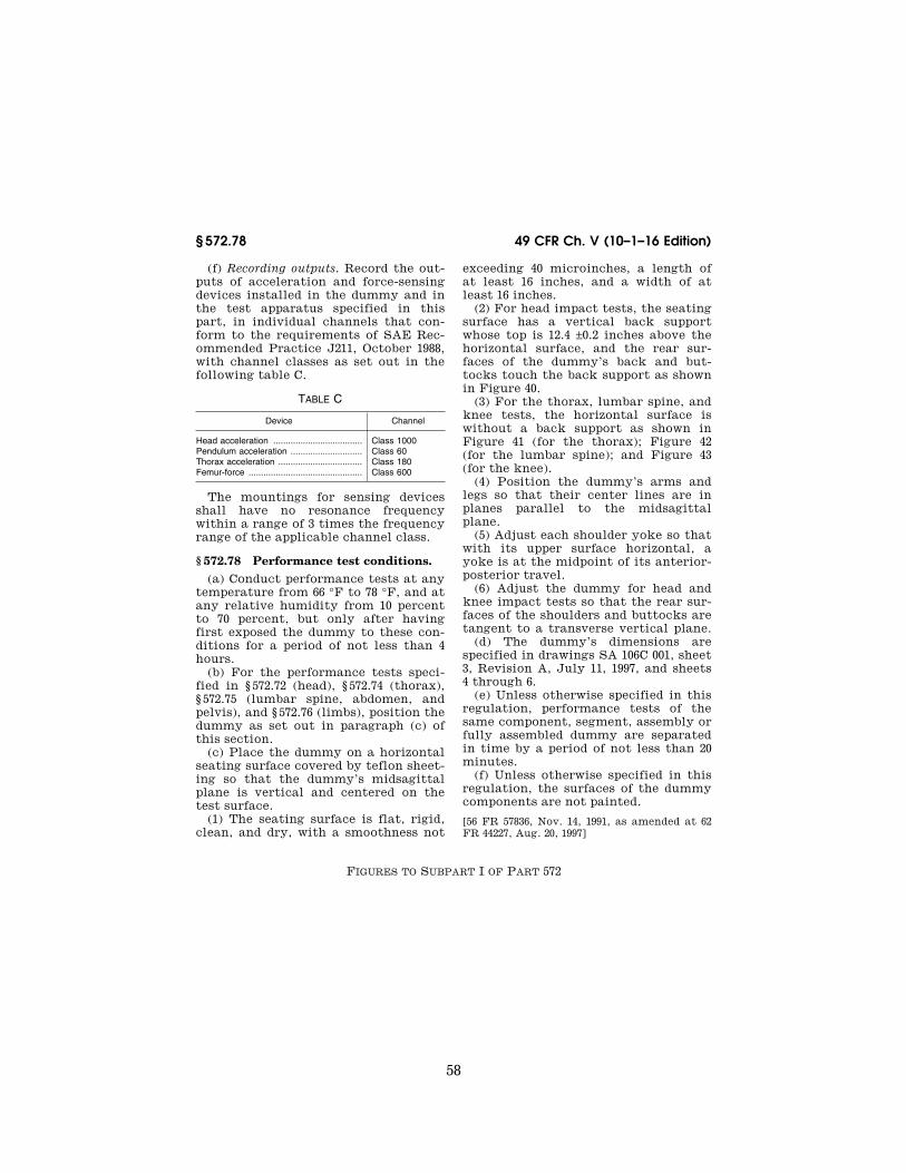
58
49 CFR Ch. V (10–1–16 Edition) § 572.78
(f) Recording outputs. Record the out-puts of acceleration and force-sensing devices installed in the dummy and in the test apparatus specified in this part, in individual channels that con-form to the requirements of SAE Rec-ommended Practice J211, October 1988, with channel classes as set out in the following table C.
TABLE C
Device Channel
Head acceleration .................................... Class 1000 Pendulum acceleration ............................. Class 60 Thorax acceleration .................................. Class 180 Femur-force .............................................. Class 600
The mountings for sensing devices shall have no resonance frequency within a range of 3 times the frequency range of the applicable channel class.
§ 572.78 Performance test conditions. (a) Conduct performance tests at any
temperature from 66 °F to 78 °F, and at any relative humidity from 10 percent to 70 percent, but only after having first exposed the dummy to these con-ditions for a period of not less than 4 hours.
(b) For the performance tests speci-fied in § 572.72 (head), § 572.74 (thorax), § 572.75 (lumbar spine, abdomen, and pelvis), and § 572.76 (limbs), position the dummy as set out in paragraph (c) of this section.
(c) Place the dummy on a horizontal seating surface covered by teflon sheet-ing so that the dummy’s midsagittal plane is vertical and centered on the test surface.
(1) The seating surface is flat, rigid, clean, and dry, with a smoothness not
exceeding 40 microinches, a length of at least 16 inches, and a width of at least 16 inches.
(2) For head impact tests, the seating surface has a vertical back support whose top is 12.4 ±0.2 inches above the horizontal surface, and the rear sur-faces of the dummy’s back and but-tocks touch the back support as shown in Figure 40.
(3) For the thorax, lumbar spine, and knee tests, the horizontal surface is without a back support as shown in Figure 41 (for the thorax); Figure 42 (for the lumbar spine); and Figure 43 (for the knee).
(4) Position the dummy’s arms and legs so that their center lines are in planes parallel to the midsagittal plane.
(5) Adjust each shoulder yoke so that with its upper surface horizontal, a yoke is at the midpoint of its anterior- posterior travel.
(6) Adjust the dummy for head and knee impact tests so that the rear sur-faces of the shoulders and buttocks are tangent to a transverse vertical plane.
(d) The dummy’s dimensions are specified in drawings SA 106C 001, sheet 3, Revision A, July 11, 1997, and sheets 4 through 6.
(e) Unless otherwise specified in this regulation, performance tests of the same component, segment, assembly or fully assembled dummy are separated in time by a period of not less than 20 minutes.
(f) Unless otherwise specified in this regulation, the surfaces of the dummy components are not painted.
[56 FR 57836, Nov. 14, 1991, as amended at 62 FR 44227, Aug. 20, 1997]
FIGURES TO SUBPART I OF PART 572
VerDate Sep<11>2014 10:23 Mar 06, 2017 Jkt 238231 PO 00000 Frm 00068 Fmt 8010 Sfmt 8026 Y:\SGML\238231.XXX 238231jsta
llwor
th o
n D
SK
7TP
TV
N1P
RO
D w
ith C
FR

59
Nat’l Highway Traffic Safety Admin., DOT Pt. 572, Subpt. I, Fig. 40
VerDate Sep<11>2014 10:23 Mar 06, 2017 Jkt 238231 PO 00000 Frm 00069 Fmt 8010 Sfmt 8006 Y:\SGML\238231.XXX 238231 EC
01A
U91
.169
</G
PH
>
jsta
llwor
th o
n D
SK
7TP
TV
N1P
RO
D w
ith C
FR

60
49 CFR Ch. V (10–1–16 Edition) Pt. 572, Subpt. I, Fig. 41
[60 FR 2898, Jan. 12, 1995]
VerDate Sep<11>2014 10:23 Mar 06, 2017 Jkt 238231 PO 00000 Frm 00070 Fmt 8010 Sfmt 8026 Y:\SGML\238231.XXX 238231 EC
01A
U91
.170
</G
PH
>
jsta
llwor
th o
n D
SK
7TP
TV
N1P
RO
D w
ith C
FR

61
Nat’l Highway Traffic Safety Admin., DOT Pt. 572, Subpt. I, Fig. 42
VerDate Sep<11>2014 10:23 Mar 06, 2017 Jkt 238231 PO 00000 Frm 00071 Fmt 8010 Sfmt 8006 Y:\SGML\238231.XXX 238231 EC
01A
U91
.171
</G
PH
>
jsta
llwor
th o
n D
SK
7TP
TV
N1P
RO
D w
ith C
FR

62
49 CFR Ch. V (10–1–16 Edition) Pt. 572, Subpt. I, Fig. 43
Subpart J—9-Month Old Child
SOURCE: 56 FR 41080, Aug. 19, 1991, unless otherwise noted.
§ 572.80 Incorporated materials.
The drawings and specifications re-ferred to in § 572.81(a) that are not set forth in full are hereby incorporated in
VerDate Sep<11>2014 10:23 Mar 06, 2017 Jkt 238231 PO 00000 Frm 00072 Fmt 8010 Sfmt 8002 Y:\SGML\238231.XXX 238231 EC
01A
U91
.172
</G
PH
>
jsta
llwor
th o
n D
SK
7TP
TV
N1P
RO
D w
ith C
FR
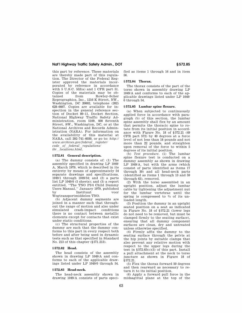
63
Nat’l Highway Traffic Safety Admin., DOT § 572.85
this part by reference. These materials are thereby made part of this regula-tion. The Director of the Federal Reg-ister approved the materials incor-porated by reference in accordance with 5 U.S.C. 552(a) and 1 CFR part 51. Copies of the materials may be ob-tained from Rowley-Scher Reprographics, Inc., 1216 K Street, NW., Washington, DC 20002, telephone (202) 628–6667. Copies are available for in-spection in the general reference sec-tion of Docket 89–11, Docket Section, National Highway Traffic Safety Ad-ministration, room 5109, 400 Seventh Street, SW., Washington, DC, or at the National Archives and Records Admin-istration (NARA). For information on the availability of this material at NARA, call 202–741–6030, or go to: http:// www.archives.gov/federallregister/ codeloflfederallregulations/ ibrllocations.html.
§ 572.81 General description. (a) The dummy consists of: (1) The
assembly specified in drawing LP 1049/ A, March 1979, which is described in its entirety by means of approximately 54 separate drawings and specifications, 1049/1 through 1049/54; and (2) a parts list LP 1049/0 (5 sheets); and (3) a report entitled, ‘‘The TNO P3/4 Child Dummy Users Manual,’’ January 1979, published by Instituut voor Wegtransportmiddelen TNO.
(b) Adjacent dummy segments are joined in a manner such that through-out the range of motion and also under simulated crash-impact conditions there is no contact between metallic elements except for contacts that exist under static conditions.
(c) The structural properties of the dummy are such that the dummy con-forms to this part in every respect both before and after being used in dynamic tests such as that specified in Standard No. 213 of this chapter (§ 571.213).
§ 572.82 Head. The head consists of the assembly
shown in drawing LP 1049/A and con-forms to each of the applicable draw-ings listed under LP 1049/0 through 54.
§ 572.83 Head-neck. The head-neck assembly shown in
drawing 1049/A consists of parts speci-
fied as items 1 through 16 and in item 56.
§ 572.84 Thorax. The thorax consists of the part of the
torso shown in assembly drawing LP 1049/A and conforms to each of the ap-plicable drawings listed under LP 1049/ 0 through 54.
§ 572.85 Lumbar spine flexure. (a) When subjected to continuously
applied force in accordance with para-graph (b) of this section, the lumbar spine assembly shall flex by an amount that permits the thoracic spine to ro-tate from its initial position in accord-ance with Figure No. 18 of § 572.21 (49 CFR part 572) by 40 degrees at a force level of not less than 18 pounds and not more than 22 pounds, and straighten upon removal of the force to within 5 degrees of its initial position.
(b) Test procedure. (1) The lumbar spine flexure test is conducted on a dummy assembly as shown in drawing LP 1049/A, but with the arms (which consist of parts identified as items 17 through 30) and all head-neck parts (identified as items 1 through 13 and 59 through 63), removed.
(2) With the torso assembled in an upright position, adjust the lumbar cable by tightening the adjustment nut for the lumbar vertebrae until the spring is compressed to 2⁄3 of its un-loaded length.
(3) Position the dummy in an upright seated position on a seat as indicated in Figure No. 18 of § 572.21 (lower legs do not need to be removed, but must be clamped firmly to the seating surface), ensuring that all dummy component surfaces are clean, dry and untreated unless otherwise specified.
(4) Firmly affix the dummy to the seating surface through the pelvis at the hip joints by suitable clamps that also prevent any relative motion with respect to the upper legs during the test in § 572.65(c)(3) of this part. Install a pull attachment at the neck to torso juncture as shown in Figure 18 of § 572.21.
(5) Flex the thorax forward 50 degrees and then rearward as necessary to re-turn it to its initial position.
(6) Apply a forward pull force in the midsagittal plane at the top of the
VerDate Sep<11>2014 10:23 Mar 06, 2017 Jkt 238231 PO 00000 Frm 00073 Fmt 8010 Sfmt 8002 Y:\SGML\238231.XXX 238231jsta
llwor
th o
n D
SK
7TP
TV
N1P
RO
D w
ith C
FR

64
49 CFR Ch. V (10–1–16 Edition) § 572.86
neck adapter so that at 40 degrees of the lumbar spine flexion the applied force is perpendicular to the thoracic spine box. Apply the force at any torso deflection rate between 0.5 and 1.5 de-grees per second up to 40 degrees of flexion but no further; maintain 40 de-grees of flexion for 10 seconds, and record the highest applied force during that time. Release all force as rapidly as possible and measure the return angle three minutes after release.
§ 572.86 Test conditions and dummy adjustment.
(a) With the complete torso on its back lying on a horizontal surface and the neck assembly mounted and shoul-ders on the edge of the surface, adjust the neck such that the head bolt is lowered 0.40 ±0.05 inches (10 ±1 mm) after a vertically applied load of 11.25 pounds (50 N) applied to the head bolt is released.
(b) With the complete torso on its back with the adjusted neck assembly as specified in § 572.66(a), and lying on a horizontal surface with the shoulders on the edge of the surface, mount the head and tighten the head bolt and nut firmly, with the head in horizontal po-sition. Adjust the head joint at the force between 1–2g, which just supports the head’s weight.
(c) Using the procedures described below, limb joints are set at the force between 1–2g, which just supports the limbs’ weight when the limbs are ex-tended horizontally forward:
(1) With the complete torso lying with its front down on a horizontal sur-face, with the hip joint just over the edge of the surface, mount the upper leg and tighten hip joint nut firmly. Adjust the hip joint by releasing the hip joint nut until the upper leg just starts moving.
(2) With the complete torso and upper leg lying with its front up on a hori-zontal surface, with the knee joint just over the edge of the surface, mount the lower leg and tighten knee joint firm-ly. Adjust the knee joint by releasing the knee joint nut until the lower leg just starts moving.
(3) With the torso in an upright posi-tion, mount the upper arm and tighten firmly the adjustment bolts for the shoulder joint with the upper arm
placed in a horizontal position. Adjust the shoulder joint by releasing the shoulder joint nut until the upper arm just starts moving.
(4) With the complete torso in an up-right position and upper arm in a vertical position, mount the forearm in a horizontal position and tighten the elbow hinge bolt and nut firmly. Adjust the elbow joint nut until the forearm just starts moving.
(d) With the torso assembled in an upright position, the adjustment nut for the lumbar vertebrae is tightened until the spring is compressed to 2⁄3 of its unloaded length.
(e) Performance tests are conducted at any temperature from 66 to 78 de-grees F and at any relative humidity from 10 percent to 70 percent after ex-posure of the dummy to these condi-tions for a period of not less than four hours.
(f) Performance tests of the same component, segment, assembly or fully assembled dummy are separated in time by a period of not less than 20 minutes unless otherwise specified.
(g) Surfaces of the dummy compo-nents are not painted except as speci-fied in the part or in drawings incor-porated by this part.
Subpart K—Newborn Infant
SOURCE: 58 FR 3232, Jan. 8, 1993, unless oth-erwise noted.
§ 572.90 Incorporation by reference.
(a) The drawings and specifications referred to in § 572.91(a) are hereby in-corporated in subpart K by reference. These materials are thereby made part of this regulation. The Director of the Federal Register approved that mate-rials incorporated by reference in ac-cordance with 5 U.S.C. 552(a) and 1 CFR part 51. Copies of the materials may be inspected at NHTSA’s Docket Section, 400 Seventh Street, SW., room 5109, Washington, DC, or at the National Ar-chives and Records Administration (NARA). For information on the avail-ability of this material at NARA, call 202–741–6030, or go to: http:// www.archives.gov/federallregister/ codeloflfederallregulations/ ibrllocations.html.
VerDate Sep<11>2014 10:23 Mar 06, 2017 Jkt 238231 PO 00000 Frm 00074 Fmt 8010 Sfmt 8002 Y:\SGML\238231.XXX 238231jsta
llwor
th o
n D
SK
7TP
TV
N1P
RO
D w
ith C
FR

65
Nat’l Highway Traffic Safety Admin., DOT § 572.101
(b) The incorporated material is available as follows:
(1) Drawing numbers 126–0000 through 126–0015 (sheets 1 through 3), 126–0017 through 126–0027, and a parts list enti-tled ‘‘Parts List for CAMI Newborn Dummy,’’ are available from Reprographic Technologies, 1111 14th Street, NW., Washington, DC 20005. (202) 628–6667.
(2) A construction manual entitled, ‘‘Construction of the Newborn Infant Dummy’’ (July 1992) is available from Reprographic Technologies at the ad-dress in paragraph (b)(1) of this section.
§ 572.91 General description. (a) The representative newborn in-
fant dummy consists of a drawings and specifications package that contains the following materials:
(1) Drawing numbers 126–0000 through 126–0015 (sheets 1 through 3), 126–0017 through 126–0027, and a parts list enti-tled ‘‘Parts List for CAMI Newborn Dummy’’; and,
(2) A construction manual entitled, ‘‘Construction of the Newborn Infant Dummy’’ (July 1992).
(b) The structural properties of the dummy are such that the dummy con-forms to this part in every respect both before and after being used in dynamic tests specified in Standard No. 213 of this chapter (§ 571.213).
Subpart L—Free Motion Headform
SOURCE: 60 FR 43058, Aug. 18, 1995, unless otherwise noted.
§ 572.100 Incorporation by Reference. (a) The drawings and specifications
referred to in § 572.101 are hereby incor-porated in subpart L by reference. These materials are thereby made part of this regulation. The Director of the Federal Register approved the mate-rials incorporated by reference in ac-cordance with 5 U.S.C. 552(a) and 1 CFR part 51. Copies of the materials may be inspected at NHTSA’s Docket Section, 400 Seventh Street, S.W., room 5109, Washington, DC, or at the National Ar-chives and Records Administration (NARA). For information on the avail-ability of this material at NARA, call 202–741–6030, or go to: http:// www.archives.gov/federallregister/
codeloflfederallregulations/ ibrllocations.html.
(b) The incorporated material is available as follows:
(1) Drawing number 92041–001, ‘‘Head Form Assembly,’’ (November 30, 1992); drawing number 92041–002, ‘‘Skull As-sembly,’’ (November 30, 1992); drawing number 92041–003, ‘‘Skull Cap Plate As-sembly,’’ (November 30, 1992); drawing number 92041–004, ‘‘Skull Cap Plate,’’ (November 30, 1992); drawing number 92041–005, ‘‘Threaded Pin,’’ (November 30, 1992); drawing number 92041–006, ‘‘Hex Nut,’’ (November 30, 1992); draw-ing number 92041–008, ‘‘Head Skin with-out Nose,’’ (November 30, 1992, as amended March 6, 1995); drawing num-ber 92041–009, ‘‘Six-Axis Load Cell Sim-ulator Assembly,’’ (November 30, 1992); drawing number 92041–011, ‘‘Head Bal-last Weight,’’ (November 30, 1992); drawing number 92041–018, ‘‘Head Form Bill of Materials,’’ (November 30, 1992); drawing number 78051–148, ‘‘Skull-Head (cast) Hybrid III,’’ (May 20, 1978, as amended August 17, 1978); drawing number 78051–228/78051–229, ‘‘Skin- Hy-brid III,’’ (May 20, 1978, as amended through September 24, 1979); drawing number 78051–339, ‘‘Pivot Pin-Neck Transducer,’’ (May 20, 1978, as amended May 14, 1986); drawing number 78051– 372, ‘‘Vinyl Skin Formulation Hybrid III,’’ (May 20, 1978); and drawing num-ber C–1797, ‘‘Neck Blank, (August 1, 1989); drawing number SA572–S4, ‘‘Ac-celerometer Specification,’’ (November 30, 1992), are available from Reprographic Technologies, 1111 14th Street, N.W., Washington, DC 20005.
(2) A user’s manual entitled ‘‘Free- Motion Headform User’s Manual,’’ version 2, March 1995, is available from NHTSA’s Docket Section at the ad-dress in paragraph (a) of this section.
(3) SAE Recommended Practice J211, OCT 1988, ‘‘Instrumentation for Impact Tests,’’ Class 1000, is available from The Society of Automotive Engineers, Inc., 400 Commonwealth Drive, Warrendale, PA 15096.
§ 572.101 General description. (a) The free motion headform con-
sists of the component assembly which is shown in drawings 92041–001 (incor-porated by reference; see § 572.100), 92041–002 (incorporated by reference;
VerDate Sep<11>2014 10:23 Mar 06, 2017 Jkt 238231 PO 00000 Frm 00075 Fmt 8010 Sfmt 8002 Y:\SGML\238231.XXX 238231jsta
llwor
th o
n D
SK
7TP
TV
N1P
RO
D w
ith C
FR

66
49 CFR Ch. V (10–1–16 Edition) § 572.102
see § 572.100), 92041–003 (incorporated by reference; see § 572.100), 92041–004 (incor-porated by reference; see § 572.100), 92041–005 (incorporated by reference; see § 572.100), 92041–006 (incorporated by reference; see § 572.100), 92041–008 (incor-porated by reference; see § 572.100), 92041–009 (incorporated by reference; see § 572.100), 92041–011 (incorporated by reference; see § 572.100), 78051–148 (incor-porated by reference; see § 572.100), 78051–228/78051–229 (incorporated by ref-erence; see § 572.100), 78051–339 (incor-porated by reference; see § 572.100), 78051–372 (incorporated by reference; see § 572.100), C–1797 (incorporated by reference; see § 572.100), and SA572–S4 (incorporated by reference; see § 572.100).
(b) Disassembly, inspection, and as-sembly procedures, and sign conven-tion for the signal outputs of the free motion headform accelerometers, are set forth in the Free-Motion Headform User’s Manual (incorporated by ref-erence; see § 572.100).
(c) The structural properties of the headform are such that it conforms to this part in every respect both before and after being used in the test speci-fied in Standard No. 201 of this chapter (§ 571.201).
(d) The outputs of accelerometers in-stalled in the headform are recorded in individual data channels that conform to the requirements of SAE Rec-ommended Practice J211, OCT 1988, ‘‘Instrumentation for Impact Tests,’’ Class 1000 (incorporated by reference; see § 572.100).
§ 572.102 Drop test. (a) When the headform is dropped
from a height of 14.8 inches in accord-ance with paragraph (b) of this section, the peak resultant accelerations at the location of the accelerometers mount-ed in the headform as shown in drawing 92041–001 (incorporated by reference; see § 572.100) shall not be less than 225g, and not more than 275g. The accelera-tion/time curve for the test shall be unimodal to the extent that oscilla-tions occurring after the main accel-eration pulse are less than ten percent (zero to peak) of the main pulse. The lateral acceleration vector shall not exceed 15g (zero to peak).
(b) Test procedure. (1) Soak the headform in a test environment at any temperature between 19 degrees C. to 26 degrees C. and at a relative humidity from 10 percent to 70 percent for a pe-riod of at least four hours prior to its use in a test.
(2) Clean the headform’s skin surface and the surface of the impact plate with 1,1,1 Trichloroethane or equiva-lent.
(3) Suspend the headform, as shown in Figure 50. Position the forehead below the chin such that the skull cap plate is at an angle of 28.5 ±0.5 degrees with the impact surface when the midsagittal plane is vertical.
(4) Drop the headform from the speci-fied height by means that ensure in-stant release onto a rigidly supported flat horizontal steel plate, which is 2 inches thick and 2 feet square. The plate shall have a clean, dry surface and any microfinish of not less than 8 microinches 203.2 × 10¥6 mm (rms) and not more than 80 microinches 2032 × 10¥6 mm (rms).
(5) Allow at least 3 hours between successive tests on the same headform.
§ 572.103 Test conditions and instru-mentation.
(a) Headform accelerometers shall have dimensions, response characteris-tics, and sensitive mass locations spec-ified in drawing SA572–S4 (incorporated by reference; see § 572.100) and be mounted in the headform as shown in drawing 92041–001 (incorporated by ref-erence; see § 572.100).
(b) The outputs of accelerometers in-stalled in the headform are recorded in individual data channels that conform to the requirements of SAE Rec-ommended Practice J211, OCT 1988, ‘‘Instrumentation for Impact Tests,’’ Class 1000 (incorporated by reference; see § 572.100).
(c) Coordinate signs for instrumenta-tion polarity conform to the sign con-vention shown in the Free-Motion Headform User’s Manual (incorporated by reference; see § 572.100).
(d) The mountings for accelerometers shall have no resonant frequency with-in a range of 3 times the frequency range of the applicable channel class.
VerDate Sep<11>2014 10:23 Mar 06, 2017 Jkt 238231 PO 00000 Frm 00076 Fmt 8010 Sfmt 8002 Y:\SGML\238231.XXX 238231jsta
llwor
th o
n D
SK
7TP
TV
N1P
RO
D w
ith C
FR

67
Nat’l Highway Traffic Safety Admin., DOT § 572.103
[60 FR 43060, Aug. 18, 1995]
VerDate Sep<11>2014 10:23 Mar 06, 2017 Jkt 238231 PO 00000 Frm 00077 Fmt 8010 Sfmt 8026 Y:\SGML\238231.XXX 238231 EC
01A
U91
.173
</G
PH
>
jsta
llwor
th o
n D
SK
7TP
TV
N1P
RO
D w
ith C
FR

68
49 CFR Ch. V (10–1–16 Edition) § 572.110
Subpart M—Side Impact Hybrid Dummy 50th Percentile Male
SOURCE: 63 FR 41470, Aug. 4, 1998, unless otherwise noted.
§ 572.110 Materials incorporated by reference.
(a) The following materials are here-by incorporated by reference in Sub-part M:
(1) The Anthropomorphic Test Dummy Parts List, SID/Hybrid III part 572, subpart M, dated May 10, 1997.
(2) The SID/Hybrid III Part 572 Sub-part M User’s Manual, dated May 1997.
(3) Drawing number 96–SIDH3–001, ti-tled, ‘‘Head-Neck Bracket,’’ dated Au-gust 30, 1996.
(4) Drawing number 96–SIDH3–006, ti-tled, ‘‘Upper and Middle Shoulder Foam,’’ dated May 10, 1997.
(5) Drawing number SA-SIDH3-M001, titled, ‘‘Complete Assembly SIDH3,’’ dated April 19, 1997.
(6) Drawing number 78051–61X, Revi-sion C, titled ‘‘Head Assembly—com-plete,’’ dated March 28, 1997
(7) Drawing number 78051–90, Revi-sion A, titled ‘‘Neck Assembly—com-plete,’’ dated May 20, 1978.
(8) Dummy assembly drawing number SA-SID-M030, Revision A, titled ‘‘Tho-rax Assembly—complete,’’ dated May 18, 1994.
(9) Dummy assembly drawing SA- SID-M050, revision A, titled ‘‘Lumbar Spine Assembly,’’ dated May 18, 1994.
(10) Dummy assembly drawing SA–150 M060, revision A, titled ‘‘Pelvis and Ab-domen Assembly,’’ dated May 18, 1994.
(11) Dummy assembly drawing SA- SID-053, revision A, titled ‘‘Lumbar Spine Assembly,’’ dated May 18, 1994.
(12) Dummy assembly drawing SA- SID-M080, titled ‘‘Leg Assembly, Right,’’ dated August 13, 1987.
(13) Dummy assembly drawing SA- SID-M081, titled ‘‘Leg Assembly, Left,’’ dated August 13, 1987.
(14) Drawing number 78051–383X, Re-vision P, titled ‘‘Neck Transducer Structural Replacement,’’ dated No-vember 1, 1995.
(15) The Society of Automotive Engi-neers (SAE) J1733 Information Report, titled ‘‘Sign Convention for Vehicle Crash Testing,’’ dated December 1994.
(16) SAE Recommended Practice J211, ‘‘Instrumentation for Impact Tests,’’ Parts 1 and 2, dated March 1995.
(b) The incorporated materials are available as follows:
(1) The Director of the Federal Reg-ister approved those materials incor-porated by reference in accordance with 5 U.S.C. 552(a) and 1 CFR part 51. Copies of the materials may be in-spected at NHTSA’s Docket Section, 400 Seventh Street S.W., room 5109, Washington, DC, or at the National Ar-chives and Records Administration (NARA). For information on the avail-ability of this material at NARA, call 202–741–6030, or go to: http:// www.archives.gov/federallregister/ codeloflfederallregulations/ ibrllocations.html.
(2) The parts lists, user’s manual and drawings referred to in paragraphs (a)(1) through (a)(14) of this section are available from Reprographic Tech-nologies, 9000 Virginia Manor Road, Beltsville, MD 20705 (301) 419–5070.
(3) The SAE materials referred to in paragraphs (a)(15) and (a)(16) of this section are available from the Society of Automotive Engineers, Inc., 400 Commonwealth Drive, Warrendale, PA 15096.
§ 572.111 General description.
(a) The dummy consists of compo-nent parts and component assemblies defined in drawing SA-SIDH3-M001, dated April 19, 1997, which are de-scribed in approximately 200 drawings and specifications that are set forth in §§ 572.32, 572.33 and 572.41(a)(3),(4),(5) and (6) of this part, and in the drawing of the Adaptor Bracket 96–SIDH3–001.
(1) The head assembly consists of the assembly specified in subpart E (§ 572.32) and conforms to each of the drawings subtended under drawing 78051–61X rev. C.
(2) The neck assembly consists of the assembly specified in subpart E (§ 572.33) and conforms to each of the drawings subtended under drawing 78051–90 rev. A.
(3) The thorax assembly consists of the assembly shown as number SID 053 and conforms to each applicable draw-ing subtended by number SA-SID M030 rev. A.
VerDate Sep<11>2014 10:23 Mar 06, 2017 Jkt 238231 PO 00000 Frm 00078 Fmt 8010 Sfmt 8002 Y:\SGML\238231.XXX 238231jsta
llwor
th o
n D
SK
7TP
TV
N1P
RO
D w
ith C
FR

69
Nat’l Highway Traffic Safety Admin., DOT § 572.112
(4) The lumbar spine consists of the assembly specified in subpart B (§ 572.9(a)) and conforms to drawing SA 150 M050 and drawings subtended by SA-SID M050 rev. A.
(5) The abdomen and pelvis consist of the assembly and conform to the draw-ings subtended by SA 150 M060, the drawings subtended by SA 150 M060 rev. A and the drawings subtended by SA- SID-087 sheet 1 rev. H, and SA-SID-87 sheet 2 rev. H.
(6) The lower limbs consist of the as-semblies specified in Subpart B (§ 572.10) shown as SA 150 M080 and SA 150 M081 in Figure 1 and SA-SID-M080 and SA-SID-M081 and conform to the drawings subtended by those numbers.
(7) The neck mounting adaptor bracket conforms to drawing 96–SIDH3– 001.
(8) Upper and middle shoulder foams conform to drawing 96–SIDH3–006.
(b) The structural properties of the dummy are such that the dummy con-forms to the specifications of this sub-part in every respect before being used in vehicle tests specified in Standard 201.
(c) Disassembly, inspection and as-sembly procedures, external dimen-sions, weight and drawing list are set forth in the SIDH3 User’s Manual, dated May 1997.
(d) Sign convention for signal out-puts is given in the reference document SAE J1733 of 1994–12, ‘‘Sign Convention for Vehicle Crash Testing.’’
§ 572.112 Head assembly. The head assembly consists of the
head (drawing 78051–61X, rev. C) with the neck transducer structural replace-ment (drawing 78051–383X, rev. P) and three (3) accelerometers that are mounted in conformance to § 572.36 (c).
(a) Test procedure. (1) Soak the head assembly in a test environment at any temperature between 18.9 and 25.6 de-grees C. (66 to 78 degrees F.) and at a relative humidity between 10 percent and 70 percent for a period of at least four (4) hours prior to its application in a test.
(2) Clean the impact surface of the head skin and impact plate surface, de-scribed in paragraph (a)(4) of this sec-tion, with 1,1,1 trichloroethane or equivalent prior to the test.
(3) Suspend the head, as shown in Figure 51, so that the midsagittal plane makes an angle of 35 ±1 degrees with the impact surface and its anterior- posterior axis is horizontal ±1 degree.
(4) Drop the head from a height of 200 ±0.25 mm (7.87 ±0.01 inches), measured from the lowest point on the head, by a means that ensures a smooth, clean re-lease into a rigidly supported flat hori-zontal steel plate, which is 51 ±2 mm (2.0 ±0.01 in.) thick and 610 ±10 mm (24.0 ±0.4 in) square. The plate shall have a dry surface and shall have a micro-finish of 0.2 microns (8 microinches) to 2.0 microns (80 microinches).
(5) Allow at least two (2) hours be-tween successive tests on the same head.
(b) Performance criteria. (1) When the head assembly is dropped in accord-ance with § 572.112(a), the measured peak resultant acceleration shall be be-tween 120 and 150 G’s.
(2) The resultant acceleration-time curve shall be unimodal to the extent that oscillations occurring after the main acceleration pulse shall not ex-ceed 15 percent (zero to peak) of the main pulse. The longitudinal accelera-tion vector shall not exceed 15 G’s.
VerDate Sep<11>2014 10:23 Mar 06, 2017 Jkt 238231 PO 00000 Frm 00079 Fmt 8010 Sfmt 8002 Y:\SGML\238231.XXX 238231jsta
llwor
th o
n D
SK
7TP
TV
N1P
RO
D w
ith C
FR

70
49 CFR Ch. V (10–1–16 Edition) § 572.113
§ 572.113 Neck assembly.
The head/neck assembly consists of the parts 78051–61X, rev. C; –84; –90, rev. A; –94; –98; –104, revision F; –303, rev.
E;—305; –306; –307, rev. X and has a six axis neck transducer (drawing C–1709, revision D) installed in conformance with § 572.36(d).
VerDate Sep<11>2014 10:23 Mar 06, 2017 Jkt 238231 PO 00000 Frm 00080 Fmt 8010 Sfmt 8002 Y:\SGML\238231.XXX 238231 ER
04A
U98
.003
</G
PH
>
jsta
llwor
th o
n D
SK
7TP
TV
N1P
RO
D w
ith C
FR
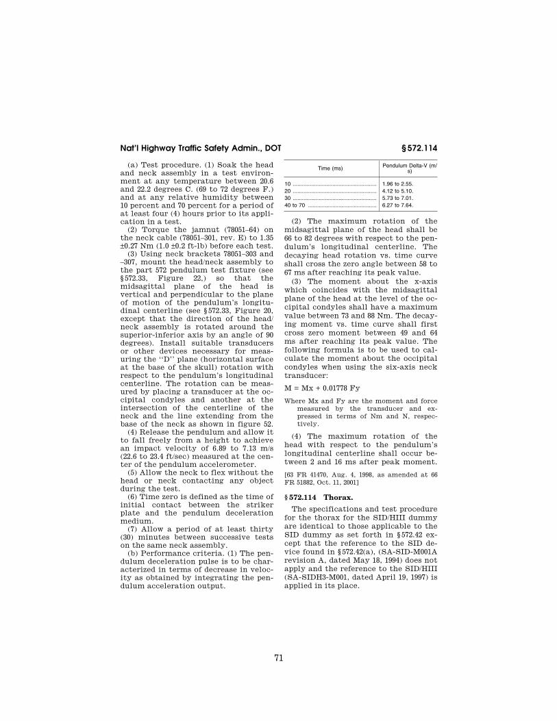
71
Nat’l Highway Traffic Safety Admin., DOT § 572.114
(a) Test procedure. (1) Soak the head and neck assembly in a test environ-ment at any temperature between 20.6 and 22.2 degrees C. (69 to 72 degrees F.) and at any relative humidity between 10 percent and 70 percent for a period of at least four (4) hours prior to its appli-cation in a test.
(2) Torque the jamnut (78051–64) on the neck cable (78051–301, rev. E) to 1.35 ±0.27 Nm (1.0 ±0.2 ft-lb) before each test.
(3) Using neck brackets 78051–303 and –307, mount the head/neck assembly to the part 572 pendulum test fixture (see § 572.33, Figure 22,) so that the midsagittal plane of the head is vertical and perpendicular to the plane of motion of the pendulum’s longitu-dinal centerline (see § 572.33, Figure 20, except that the direction of the head/ neck assembly is rotated around the superior-inferior axis by an angle of 90 degrees). Install suitable transducers or other devices necessary for meas-uring the ‘‘D’’ plane (horizontal surface at the base of the skull) rotation with respect to the pendulum’s longitudinal centerline. The rotation can be meas-ured by placing a transducer at the oc-cipital condyles and another at the intersection of the centerline of the neck and the line extending from the base of the neck as shown in figure 52.
(4) Release the pendulum and allow it to fall freely from a height to achieve an impact velocity of 6.89 to 7.13 m/s (22.6 to 23.4 ft/sec) measured at the cen-ter of the pendulum accelerometer.
(5) Allow the neck to flex without the head or neck contacting any object during the test.
(6) Time zero is defined as the time of initial contact between the striker plate and the pendulum deceleration medium.
(7) Allow a period of at least thirty (30) minutes between successive tests on the same neck assembly.
(b) Performance criteria. (1) The pen-dulum deceleration pulse is to be char-acterized in terms of decrease in veloc-ity as obtained by integrating the pen-dulum acceleration output.
Time (ms) Pendulum Delta-V (m/ s)
10 ....................................................... 1.96 to 2.55. 20 ....................................................... 4.12 to 5.10. 30 ....................................................... 5.73 to 7.01. 40 to 70 ............................................. 6.27 to 7.64.
(2) The maximum rotation of the midsagittal plane of the head shall be 66 to 82 degrees with respect to the pen-dulum’s longitudinal centerline. The decaying head rotation vs. time curve shall cross the zero angle between 58 to 67 ms after reaching its peak value.
(3) The moment about the x-axis which coincides with the midsagittal plane of the head at the level of the oc-cipital condyles shall have a maximum value between 73 and 88 Nm. The decay-ing moment vs. time curve shall first cross zero moment between 49 and 64 ms after reaching its peak value. The following formula is to be used to cal-culate the moment about the occipital condyles when using the six-axis neck transducer:
M = Mx + 0.01778 Fy
Where Mx and Fy are the moment and force measured by the transducer and ex-pressed in terms of Nm and N, respec-tively.
(4) The maximum rotation of the head with respect to the pendulum’s longitudinal centerline shall occur be-tween 2 and 16 ms after peak moment.
[63 FR 41470, Aug. 4, 1998, as amended at 66 FR 51882, Oct. 11, 2001]
§ 572.114 Thorax.
The specifications and test procedure for the thorax for the SID/HIII dummy are identical to those applicable to the SID dummy as set forth in § 572.42 ex-cept that the reference to the SID de-vice found in § 572.42(a), (SA-SID-M001A revision A, dated May 18, 1994) does not apply and the reference to the SID/HIII (SA-SIDH3-M001, dated April 19, 1997) is applied in its place.
VerDate Sep<11>2014 10:23 Mar 06, 2017 Jkt 238231 PO 00000 Frm 00081 Fmt 8010 Sfmt 8002 Y:\SGML\238231.XXX 238231jsta
llwor
th o
n D
SK
7TP
TV
N1P
RO
D w
ith C
FR

72
49 CFR Ch. V (10–1–16 Edition) § 572.115
§ 572.115 Lumbar spine and pelvis.
The specifications and test procedure for the lumbar spine and pelvis are identical to those for the SID dummy as set forth in § 572.42 except that the reference to the SID device found in § 572.42(a), (SA-SID-M001A revision A, dated May 18, 1994) does not apply and the reference to the SID/HIII (SA-
SIDH3-M001, dated April 19, 1997) is ap-plied in its place.
§ 572.116 Instrumentation and test conditions.
(a) The test probe for lateral thoracic and pelvis impact tests are the same as those specified in § 572.44(a).
VerDate Sep<11>2014 10:23 Mar 06, 2017 Jkt 238231 PO 00000 Frm 00082 Fmt 8010 Sfmt 8002 Y:\SGML\238231.XXX 238231 ER
04A
U98
.004
</G
PH
>
jsta
llwor
th o
n D
SK
7TP
TV
N1P
RO
D w
ith C
FR

73
Nat’l Highway Traffic Safety Admin., DOT § 572.120
(b) Accelerometer mounting in the thorax is the same as specified in § 572.44(b).
(c) Accelerometer mounting in the pelvis is the same as specified in § 572.44(c).
(d) Head accelerometer mounting is the same as specified in § 572.36(c).
(e) Neck transducer mounting is the same as specified in § 572.36(d).
(f) Instrumentation and sensors used must conform to SAE Recommended Practice J211, March 1995, ‘‘Instrumen-tation for Impact Tests.’’
(g) The mountings for the spine, rib and pelvis accelerometers shall have no resonance frequency within a range of 3 times the frequency range of the appli-cable channel class.
(h) Limb joints of the test dummy shall be set at the force between 1 to 2 g’s, which just supports the limb’s weight when the limbs are extended horizontally forward. The force re-quired to move a limb segment does not exceed 2 g’s throughout the range of the limb motion.
(i) Performance tests must be con-ducted at a temperature between 20.6 and 22.2 degrees C. (69 to 72 degrees F.) and at a relative humidity between 10 percent and 70 percent after exposure of the dummy to those conditions for a period of at least four (4) hours.
(j) For the performance of tests speci-fied in § 572.114 and § 572.115, the dummy is positioned the same as specified in § 572.44(h).
Subpart N—Six-year-old Child Test Dummy, Beta Version
SOURCE: 65 FR 2065, Jan. 13, 2000, unless otherwise noted.
§ 572.120 Incorporation by reference. (a) The following materials are here-
by incorporated into this subpart by reference:
(1) A drawings and inspection pack-age entitled, ‘‘Parts List and Drawings, Part 572 Subpart N, Hybrid III Six-Year Old Child Crash Test Dummy (H–III6C, Beta Version), June 2009,’’ consisting of:
(i) Drawing No. 127–1000, 6-year H3 Head Complete, incorporated by ref-erence in § 572.122,
(ii) Drawing No. 127–1015, Neck As-sembly, incorporated by reference in § 572.123,
(iii) Drawing No. 127–2000, Upper Torso Assembly, incorporated by ref-erence in § 572.124,
(iv) Drawing No. 127–3000, Lower Torso Assembly, incorporated by ref-erence in § 572.125,
(v) Drawing No. 127–4000–1 and 4000–2, Leg Assembly, incorporated by ref-erence in § 572.126,
(vi) Drawing No. 127–5000–1 and 5000–2, Arm Assembly, incorporated by ref-erence in §§ 572.121, 572.124, and 572.125 as part of a complete dummy assembly, and,
(vii) Parts List and Drawings, Hybrid III Six-year-old Child Test Dummy (H– III6C, Beta Version), dated June 1, 2009, incorporated by reference in § 572.121;
(2) A procedures manual entitled ‘‘Procedures for Assembly, Dis-assembly, and Inspection (PADI) of the Hybrid III 6-year-old Child Crash Test Dummy (H–III6C), Beta Version, June 1, 2009,’’ incorporated by reference in § 572.121;
(3) SAE Recommended Practice J211– 1995, ‘‘Instrumentation for Impact Tests—Parts 1 and 2, dated March, 1995,’’ incorporated by reference in § 572.127;
(4) SAE J1733 Information Report, ti-tled ‘‘Sign Convention for Vehicle Crash Testing,’’ dated December 1994, incorporated by reference in § 572.127.
(b) The Director of the Federal Reg-ister approved the materials incor-porated by reference in accordance with 5 U.S.C. 552(a) and 1 CFR part 51. Copies of the materials may be in-spected at the Department of Transpor-tation, Docket Operations, Room W12– 140, 1200 New Jersey Avenue, SE., Washington, DC 20590, telephone (202) 366–9826, and at the National Archives and Records Administration (NARA), and in electronic format through Regu-lations.gov. For information on the availability and inspection of this ma-terial at NARA, call 202–741–6030, or go to: http://www.archives.gov/ federallregister/ codeloflfederallregulations/ ibrllocations.html. For information on the availability and inspection of this material at Regulations.gov, call 1–877–
VerDate Sep<11>2014 10:23 Mar 06, 2017 Jkt 238231 PO 00000 Frm 00083 Fmt 8010 Sfmt 8002 Y:\SGML\238231.XXX 238231jsta
llwor
th o
n D
SK
7TP
TV
N1P
RO
D w
ith C
FR

74
49 CFR Ch. V (10–1–16 Edition) § 572.121
378–5457, or go to: http:// www.regulations.gov.
(c) The incorporated materials are available as follows:
(1) The drawings and specifications package, the parts list, and the PADI document referred to in paragraphs (a)(1), and (a)(2) of this section, are available in electronic format through www.Regulations.gov and in paper for-mat from Leet-Melbrook, Division of New RT, 18810 Woodfield Road, Gai-thersburg, MD 20879, (301) 670–0090.
(2) The SAE materials referred to in paragraphs (a)(3) and (a)(4) of this sec-tion are available from the Society of Automotive Engineers, Inc., 400 Com-monwealth Drive, Warrendale, PA 15096.
[65 FR 2065, Jan. 13, 2000, as amended at 67 FR 47327, July 18, 2002; 75 FR 76645, Dec. 9, 2010]
§ 572.121 General description. (a) The Hybrid III type 6-year-old
dummy is defined by drawings and specifications containing the following materials:
(1) Technical drawings and specifica-tions package P/N 127–0000, the titles of which are listed in Table A;
(2) Procedures for Assembly, Dis-assembly, and Inspection (PADI) of the Hybrid III 6-year-old child crash test dummy (H–III6C), Beta version, dated June 1, 2009, incorporated by reference in § 572.120.
TABLE A
Component assembly Drawing number
Head assembly .................................................... 127–1000 Neck assembly .................................................... 127–1015 Upper torso assembly ......................................... 127–2000 Lower torso assembly ......................................... 127–3000 Leg assembly ...................................................... 127–4000 Arm assembly ...................................................... 127–5000
(b) Adjacent segments are joined in a manner such that except for contacts existing under static conditions, there is no contact between metallic ele-ments throughout the range of motion or under simulated crash impact condi-tions.
(c) The structural properties of the dummy are such that the dummy must conform to this Subpart in every re-spect before use in any test similar to those specified in Standard 208, ‘‘Occu-
pant Crash Protection’’, and Standard 213, ‘‘Child Restraint Systems’’.
[65 FR 2065, Jan. 13, 2000, as amended at 75 FR 76645, Dec. 9, 2010]
§ 572.122 Head assembly and test pro-cedure.
(a) The head assembly for this test consists of the complete head (drawing 127–1000), a six-axis neck transducer (drawing SA572–S11) or its structural replacement (drawing 78051–383X), a head to neck-to-pivot pin (drawing 78051–339), and 3 accelerometers (draw-ing SA572–S4).
(b) When the head assembly in para-graph (a) of this section is dropped from a height of 376.0 ±1.0 mm (14.8 ±0.04 in) in accordance with paragraph (c) of this section, the peak resultant acceleration at the location of the accelerometers at the head CG may not be less than 245 G or more than 300 G. The resultant acceleration vs. time his-tory curve shall be unimodal; oscilla-tions occurring after the main pulse must be less than 10 percent of the peak resultant acceleration. The lat-eral acceleration shall not exceed 15 g’s (zero to peak).
(c) Head test procedure. The test pro-cedure for the head is as follows:
(1) Soak the head assembly in a con-trolled environment at any tempera-ture between 18.9 and 25.6 °C (66 and 78 °F) and a relative humidity from 10 to 70 percent for at least four hours prior to a test.
(2) Prior to the test, clean the impact surface of the skin and the impact plate surface with isopropyl alcohol, trichloroethane, or an equivalent. The skin of the head must be clean and dry for testing.
(3) Suspend the head assembly as shown in Figure N1. The lowest point on the forehead must be 376.0 ±1.0 mm (14.8 ±0.04 in) from the impact surface and the head must be oriented to an in-cline of 62 ±1 deg. between the ‘‘D’’ plane as shown in Figure N1 and the plane of the impact surface. The 1.57 mm (0.062 in) diameter holes located on either side of the dummy’s head shall be used to ensure that the head is level with respect to the impact surface.
(4) Drop the head assembly from the specified height by means that ensure a smooth, instant release onto a rigidly
VerDate Sep<11>2014 10:23 Mar 06, 2017 Jkt 238231 PO 00000 Frm 00084 Fmt 8010 Sfmt 8002 Y:\SGML\238231.XXX 238231jsta
llwor
th o
n D
SK
7TP
TV
N1P
RO
D w
ith C
FR

75
Nat’l Highway Traffic Safety Admin., DOT § 572.123
supported flat horizontal steel plate which is 50.8 mm (2 in) thick and 610 mm (24 in) square. The impact surface shall be clean, dry and have a micro finish of not less than 203.2. × 10¥6 mm (8 micro inches) (RMS) and not more than 2032.0 × 10¥6 mm (80 micro inches) (RMS).
(5) Allow at least 2 hours between successive tests on the same head.
§ 572.123 Neck assembly and test pro-cedure.
(a) The neck assembly for the pur-poses of this test consists of the assem-bly of components shown in drawing 127–1015.
(b) When the head-neck assembly consisting of the head (drawing 127– 1000), neck (drawing 127–1015), pivot pin (drawing 78051–339), bib simulator (drawing TE127–1025, neck bracket as-sembly (drawing 127–8221), six-axis neck transducer (drawing SA572–S11), neck mounting adaptor (drawing TE–2208– 001), and three accelerometers (drawing SA572–S4) installed in the head assem-bly as specified in § 572.122, is tested ac-cording to the test procedure in para-graph (c) of this section, it shall have the following characteristics:
(1) Flexion. (i) Plane D, referenced in Figure N2, shall rotate in the direction of preimpact flight with respect to the pendulum’s longitudinal centerline be-tween 74 degrees and 92 degrees. Within this specified rotation corridor, the peak moment about the occipital condyles shall be not less than 27 N-m (19.9 ft-lbf) and not more than 33 N-m (24.3 ft-lbf).
(ii) The positive moment shall decay for the first time to 5 N-m (3.7 ft-lbf) between 103 ms and 123 ms.
(iii) The moment shall be calculated by the following formula: Moment (N- m) = My¥(0.01778m) × (FX).
(iv) My is the moment about the y- axis and FX is the shear force measured by the neck transducer (drawing SA572–S11) and 0.01778m is the distance from force to occipital condyle.
(2) Extension. (i) Plane D, referenced in Figure N3, shall rotate in the direc-tion of preimpact flight with respect to the pendulum’s longitudinal centerline between 85 degrees and 103 degrees. Within this specified rotation corridor, the peak moment about the occipital
condyles shall be not more than ¥19 N- m (¥14 ft-lbf) and not less than ¥24 N- m (¥17.7ft-lbf).
(ii) The negative moment shall decay for the first time to ¥5 N-m (¥3.7 ft- lbf) between 123 ms and 147 ms.
(iii) The moment shall be calculated by the following formula: Moment (N- m) = My¥(0.01778m) × (FX).
(iv) My is the moment about the y- axis and FX is the shear force measured by the neck transducer (drawing SA572–S11) and 0.017778m is the dis-tance from force to occipital condyle.
(3) Time-zero is defined as the time of initial contact between the pendulum striker plate and the honeycomb mate-rial.
(c) Test procedure. The test procedure for the neck assembly is as follows:
(1) Soak the neck assembly in a con-trolled environment at any tempera-ture between 20.6 and 22.2 °C (69 and 72 °F) and a relative humidity between 10 and 70 percent for at least four hours prior to a test.
(2) Torque the jam nut (drawing 9000341) on the neck cable (drawing 127– 1016) to 0.23 ±0.02 N-m (2.0 ±0.2 in-lbs).
(3) Mount the head-neck assembly, defined in paragraph (b) of this section, on the pendulum so the midsagittal plane of the head is vertical and coin-cides with the plane of motion of the pendulum as shown in Figure N2 for flexion tests and Figure N3 for exten-sion tests.
(4) Release the pendulum and allow it to fall freely from a height to achieve an impact velocity of 4.95 ±0.12 m/s (16.2 ±0.4 ft/s) for flexion tests and 4.3 ±0.12 m/s (14.10 ±0.40 ft/s) for extension tests, measured by an accelerometer mount-ed on the pendulum as shown in Figure 22 of 49 CFR 572 at the instant of con-tact with the honey comb.
(i) Time-zero is defined as the time of initial contact between the pendulum striker plate and the honeycomb mate-rial. All data channels should be at the zero level at this time.
(ii) Stop the pendulum from the ini-tial velocity with an acceleration vs. time pulse which meets the velocity change as specified below. Integrate the pendulum acceleration data chan-nel to obtain the velocity vs. time curve:
VerDate Sep<11>2014 10:23 Mar 06, 2017 Jkt 238231 PO 00000 Frm 00085 Fmt 8010 Sfmt 8002 Y:\SGML\238231.XXX 238231jsta
llwor
th o
n D
SK
7TP
TV
N1P
RO
D w
ith C
FR

76
49 CFR Ch. V (10–1–16 Edition) § 572.124
TABLE B
Time Pendulum pulse
ms Flexion Extension
m/s ft/s m/s ft/s
10 .......................................................................................................... 1.2–1.6 3.9–5.3 1.0–1.4 3.3–4.6 20 .......................................................................................................... 2.4–3.4 7.9–11.2 2.2–3.0 7.2–9.8 30 .......................................................................................................... 3.8–5.0 12.5–16.4 3.2–4.2 10.5–13.8
§ 572.124 Thorax assembly and test procedure.
(a) Thorax (upper torso) assembly. The thorax consists of the part of the torso assembly shown in drawing 127–2000.
(b) When the anterior surface of the thorax of a completely assembled dummy (drawing 127–0000) is impacted by a test probe conforming to section 572.127(a) at 6.71 ±0.12 m/s (22.0 ±0.4 ft/s) according to the test procedure in paragraph (c) of this section:
(1) The maximum sternum displace-ment (compression) relative to the spine, measured with chest deflection transducer (drawing SA572-S50), must be not less than 38.0 mm (1.50 in) and not more than 46.0 mm (1.80 in). Within this specified compression corridor, the peak force, measured by the probe in accordance with section 572.127, shall not be less than 1150 N (259 lbf) and not more than 1380 N (310 lbf). The peak force after 12.5 mm (0.5 in) of sternum displacement but before reaching the minimum required 38.0 mm (1.5 in) sternum displacement limit shall not exceed 1500 N (337.2 lbf).
(2) The internal hysteresis of the ribcage in each impact as determined by the plot of force vs. deflection in paragraph (b)(1) of this section shall be not less than 65 percent but not more than 85 percent.
(c) Test procedure. The test procedure for the thorax assembly is as follows:
(1) Soak the dummy in a controlled environment at any temperature be-tween 20.6° and 22.2 °C (69° and 72 °F) and a relative humidity between 10 and 70 percent for at least four hours prior to a test.
(2) Seat and orient the dummy, wear-ing tight-fitting underwear or equiva-lent consisting of a size 5 short-sleeved shirt having a weight less than 0.090 kg (0.2 lb) and an opening at the top just large enough to permit the passage of
the head with a tight fit, and a size 4 pair of long pants having a weight of less than 0.090 kg (0.2 lb) with the legs cut off sufficiently above the knee to allow the knee target to be visible, on a seating surface without back support as shown in Figure N4, with the limbs extended horizontally and forward, par-allel to the midsagittal plane, the midsagittal plane vertical within ±1 de-gree and the ribs level in the anterior- posterior and lateral directions within ±0.5 degrees.
(3) Establish the impact point at the chest midsagittal plane so that the im-pact point of the longitudinal center-line of the probe coincides with the midsagittal plane of the dummy within ±2.5 mm (0.1 in) and is 12.7 ±1.1 mm (0.5 ±0.04 in) below the horizontal-periph-eral centerline of the No. 3 rib and is within 0.5 degrees of a horizontal line in the dummy’s midsagittal plane.
(4) Impact the thorax with the test probe so that at the moment of contact the probe’s longitudinal center line falls within 2 degrees of a horizontal line in the dummy’s midsagittal plane.
(5) Guide the test probe during im-pact so that there is no significant lat-eral, vertical or rotational movement.
(6) No suspension hardware, suspen-sion cables, or any other attachments to the probe, including the velocity vane, shall make contact with the dummy during the test.
[65 FR 2065, Jan. 13, 2000, as amended at 67 FR 47327, July 18, 2002]
§ 572.125 Upper and lower torso as-semblies and torso flexion test pro-cedure.
(a) Upper/lower torso assembly. The test objective is to determine the stiff-ness effects of the lumbar spine (draw-ing 127–3002), including cable (drawing 127–8095), mounting plate insert (draw-ing 910420–048), nylon shoulder bushing
VerDate Sep<11>2014 10:23 Mar 06, 2017 Jkt 238231 PO 00000 Frm 00086 Fmt 8010 Sfmt 8002 Y:\SGML\238231.XXX 238231jsta
llwor
th o
n D
SK
7TP
TV
N1P
RO
D w
ith C
FR

77
Nat’l Highway Traffic Safety Admin., DOT § 572.126
(drawing 9001373), nut (drawing 9001336), and abdominal insert (drawing 127– 8210), on resistance to articulation be-tween upper torso assembly (drawing 127–2000) and lower torso assembly (drawing 127–3000).
(b)(1) When the upper torso assembly of a seated dummy is subjected to a force continuously applied at the head to neck pivot pin level through a rig-idly attached adaptor bracket as shown in Figure N5 according to the test pro-cedure set out in paragraph (c) of this section, the lumbar spine-abdomen as-sembly shall flex by an amount that permits the upper torso assembly to translate in angular motion until the machined rear surface of the instru-ment cavity at the back of the thoracic spine box is at 45 ±0.5 degrees relative to the vertical transverse plane, at which time the force applied as shown in Figure N5 must be not less than 147 N (33 lbf) and not more than 200 N (45 lbf), and
(2) Upon removal of the force, the torso assembly must return to within 8 degrees of its initial position.
(c) Test procedure. The test procedure for the torso assemblies is as follows:
(1) Soak the dummy in a controlled environment at any temperature be-tween 18.9 and 25.6 °C (66 and 78 °F) and a relative humidity between 10 and 70 percent for at least four hours prior to a test.
(2) Attach the dummy (with or with-out the legs below the femurs) to the fixture in a seated posture as shown in Figure N5.
(3) Secure the pelvis at the pelvis in-strument cavity rear face by threading four 1⁄4 in cap screws into the available threaded attachment holes. Tighten the mountings so that the test mate-rial is rigidly affixed to the test fixture and the pelvic-lumbar joining surface is horizontal.
(4) Flex the thorax forward three times between vertical and until the torso reference plane, as shown in fig-ure N5, reaches 30 ±2 degrees from vertical. Bring the torso to vertical orientation, remove all externally ap-plied flexion forces, and wait 30 min-utes before conducting the test. During the 30-minute waiting period, the dum-my’s upper torso shall be externally
supported at or near its vertical ori-entation to prevent sagging.
(5) Remove the external support and wait two minutes. Measure the initial orientation of the torso reference plane of the seated, unsupported dummy as shown in Figure N5. This initial torso orientation angle may not exceed 22 de-grees.
(6) Attach the loading adapter brack-et to the spine of the dummy, the pull cable, and the load cell as shown in Figure N5.
(7) Apply a tension force in the midsagittal plane to the pull cable as shown in Figure N5 at any upper torso deflection rate between 0.5 and 1.5 de-grees per second, until the torso ref-erence plane is at 45 ±0.5 degrees of flexion relative to the vertical trans-verse plane as shown in Figure N5.
(8) Continue to apply a force suffi-cient to maintain 45 ±0.5 degrees of flexion for 10 seconds, and record the highest applied force during the 10-sec-ond period.
(9) Release all force as rapidly as pos-sible, and measure the return angle at 3 minutes or any time thereafter after the release.
§ 572.126 Knees and knee impact test procedure.
(a) Knee assembly. The knee assembly is part of the leg assembly (drawing 127–4000–1 and –2).
(b) When the knee assembly, con-sisting of knee machined (drawing 127– 4013), knee flesh (drawing 127–4011), lower leg (drawing 127–4014), the foot assembly (drawing 127–4030–1(left) and –2 (right)) and femur load transducer (drawing SA572-S10) or its structural replacement (drawing 127–4007) is test-ed according to the test procedure in section 572.127(c), the peak resistance force as measured with the test probe mounted accelerometer must be not less than 2.0 kN (450 lbf) and not more than 3.0 kN (674 lbf).
(c) Test procedure. The test procedure for the knee assembly is as follows:
(1) Soak the knee assembly in a con-trolled environment at any tempera-ture between 18.9 and 25.6 °C (66 and 78 °F) and a relative humidity from 10 to 70 percent for at least four hours prior to a test.
VerDate Sep<11>2014 10:23 Mar 06, 2017 Jkt 238231 PO 00000 Frm 00087 Fmt 8010 Sfmt 8002 Y:\SGML\238231.XXX 238231jsta
llwor
th o
n D
SK
7TP
TV
N1P
RO
D w
ith C
FR

78
49 CFR Ch. V (10–1–16 Edition) § 572.127
(2) Mount the test material and se-cure it to a rigid test fixture as shown in Figure N6. No contact is permitted between any part of the foot or tibia and any exterior surface.
(3) Align the test probe so that throughout its stroke and at contact with the knee it is within 2 degrees of horizontal and collinear with the longi-tudinal centerline of the femur.
(4) Guide the pendulum so that there is no significant lateral vertical or ro-tational movement at time-zero.
(5) The test probe velocity at the time of contact shall be 2.1 ±0.03 m/s (6.9 # 0.1 ft/s).
(6) No suspension hardware, suspen-sion cables, or any other attachments to the probe, including the velocity vane, shall make contact with the dummy during testing.
[65 FR 2065, Jan. 13, 2000, as amended at 67 FR 47328, July 18, 2002]
§ 572.127 Test conditions and instru-mentation.
(a) The test probe for thoracic im-pacts, except for attachments, shall be of rigid metal or metal alloy construc-tion and concentric about its longitu-dinal axis. Any attachments to the im-pactor, such as suspension hardware, velocity vanes, etc., must meet the re-quirements of § 572.124(c)(6). The impac-tor shall have a mass of 2.86 ±0.02 kg (6.3 ±0.05 lb) and a minimum mass mo-ment of inertia of 160 kg-c2 (0.141 lb-in- sec2) in yaw and pitch about the CG of the probe. One third of the weight of suspension cables and any attachments to the impact probe must be included in the calculation of mass, and such components may not exceed five per-cent of the total weight of the probe. The impacting end of the probe, has a flat, continuous, and non-deformable 101.6 ±0.25 mm (4.00 ±0.01 in) diameter face with an edge radius of 7.6/12.7 mm (0.3/0.5 in). The impactor shall have a 101–103 mm (4.0–4.1 in) diameter cylin-drical surface extending for a min-imum of 12.5 mm (0.5 in) to the rear from the impact face. The probe’s end opposite to the impact face has provi-sions for mounting an accelerometer with its sensitive axis collinear with the longitudinal axis of the probe. The impact probe shall have a free air reso-nant frequency of not less than 1000 Hz
limited to the direction of the longitu-dinal axis of the impactor.
(b) The test probe for knee impacts, except for attachments, shall be of rigid metal or alloy construction and concentric about its longitudinal axis. Any attachments to the impactor, such as suspension hardware, velocity vanes, etc., must meet the requirements of § 572.126(c)(6). The impactor shall have a mass of 0.82 ±0.02 kg (1.8 ±0.05 lb) and a minimum mass moment of inertia of 34 kg-cm2 (0.03 lb-in-sec2) in yaw and pitch about the CG of the probe. One third of the weight of suspension cables and any attachments to the impact probe must be included in the calcula-tion of mass, and such components may not exceed five percent of the total weight of the probe. The impact-ing end of the probe, has a flat, contin-uous, and non-deformable 76.2 ±0.2 mm (3.00 ±0.01 in) diameter face with an edge radius of 7.6/12.7 mm (0.3/0.5 in). The impactor shall have a 76–77 mm (3.0–3.1 in) diameter cylindrical surface extending for a minimum of 12.5 mm (0.5 in) to the rear from the impact face. The probe’s end opposite to the impact face has provisions for mount-ing an accelerometer with its sensitive axis collinear with the longitudinal axis of the probe. The impact probe shall have a free air resonant frequency of not less than 1000 Hz limited to the direction of the longitudinal axis of the impactor.
(c) Head accelerometers shall have dimensions, response characteristics, and sensitive mass locations specified in drawing SA572–S4 and be mounted in the head as shown in drawing 127–0000 sheet 3.
(d) Neck force/moment transducer. (1) The upper neck force/moment trans-ducer shall have the dimensions, re-sponse characteristics, and sensitive axis locations specified in drawing SA572–S11 and be mounted in the head- neck assembly as shown in drawing 127–0000 sheet 3.
(2) The optional lower neck force/mo-ment transducer shall have the dimen-sions, response characteristics, and sensitive axis locations specified in drawing SA572–S26 and be mounted as shown in drawing 127–0000 sheet 3.
VerDate Sep<11>2014 10:23 Mar 06, 2017 Jkt 238231 PO 00000 Frm 00088 Fmt 8010 Sfmt 8002 Y:\SGML\238231.XXX 238231jsta
llwor
th o
n D
SK
7TP
TV
N1P
RO
D w
ith C
FR

79
Nat’l Highway Traffic Safety Admin., DOT § 572.127
(e) The thorax accelerometers shall have the dimensions, response charac-teristics, and sensitive mass locations specified in drawing SA572–S4 and be mounted in the torso assembly in tri-axial configuration at T4, and as op-tional instrumentation in uniaxial for- and-aft oriented configuration on the most anterior ends of ribs #1 and #6 and at the spine box at the levels of #1 and #6 ribs as shown in 127–0000 sheet 3.
(f) The chest deflection transducer shall have the dimensions and response characteristics specified in drawing SA572–S50 and be mounted in the upper torso assembly as shown in 127–0000 sheet 3.
(g) The optional lumbar spine force- moment transducer shall have the di-mensions, response characteristics, and sensitive axis locations specified in drawing SA572–S12 and be mounted in the lower torso assembly as shown in drawing 127–0000 sheet 3 as a replace-ment for lumbar adaptor 127–3005.
(h) The optional iliac spine force transducers shall have the dimensions and response characteristics specified in drawing SA572–S13 and be mounted in the torso assembly as shown in drawing 127–0000 sheet 3 as a replace-ment for ASIS load cell 127–3015–1 (left) and ¥2 (right).
(i) The optional pelvis accelerometers shall have the dimen-sions, response characteristics, and sensitive mass locations specified in drawing SA572–S4 and be mounted in the torso assembly in triaxial configu-ration in the pelvis bone as shown in drawing 127–0000 sheet 3.
(j) The femur force transducer shall have the dimensions and response char-acteristics specified in drawing SA72– S10 and be mounted in the leg assembly as shown in drawing 127–0000 sheet 3.
(k) The outputs of acceleration and force-sensing devices installed in the dummy and in the test apparatus speci-fied by this part must be recorded in individual data channels that conform
to SAE Recommended Practice J211, Rev. Mar95 ‘‘Instrumentation for lmpact Tests,’’ except that the lumbar measurements are based on CFC 600, with channel classes as follows:
(1) Head acceleration—Class 1000. (2) Neck: (i) Forces—Class 1000; (ii) Moments—Class 600; (iii) Pendulum acceleration—Class
180; (iv) Rotation—Class 60 (if used). (3) Thorax: (i) Rib acceleration—Class 1000; (ii) Spine and pendulum accelera-
tions—Class 180; (iii) Sternum deflection—Class 600. (4) Lumbar: (i) Forces—Class 1000; (ii) Moments—Class 600; (iii) Flexion—Class 60 if data channel
is used. (5) Pelvis accelerations—Class 1000. (6) Femur forces—Class 600. (l) Coordinate signs for instrumenta-
tion polarity shall conform to the Sign Convention For Vehicle Crash Testing, Surface Vehicle Information Report, SAE J1733, 1994–12.
(m) The mountings for sensing de-vices shall have no resonance fre-quency less than 3 times the frequency range of the applicable channel class.
(n) Limb joints must be set at one G, barely restraining the weight of the limb when it is extended horizontally. The force needed to move a limb seg-ment shall not exceed 2G throughout the range of limb motion.
(o) Performance tests of the same component, segment, assembly, or fully assembled dummy shall be sepa-rated in time by period of not less than 30 minutes unless otherwise noted.
(p) Surfaces of dummy components may not be painted except as specified in this subpart or in drawings sub-tended by this subpart.
[65 FR 2065, Jan. 13, 2000, as amended at 67 FR 47328, July 18, 2002]
VerDate Sep<11>2014 10:23 Mar 06, 2017 Jkt 238231 PO 00000 Frm 00089 Fmt 8010 Sfmt 8002 Y:\SGML\238231.XXX 238231jsta
llwor
th o
n D
SK
7TP
TV
N1P
RO
D w
ith C
FR

80
49 CFR Ch. V (10–1–16 Edition) Pt. 572, Subpt. N, Fig. N1
FIGURES TO SUBPART N OF PART 572
VerDate Sep<11>2014 10:23 Mar 06, 2017 Jkt 238231 PO 00000 Frm 00090 Fmt 8010 Sfmt 8006 Y:\SGML\238231.XXX 238231 ER
18JY
02.0
00<
/GP
H>
jsta
llwor
th o
n D
SK
7TP
TV
N1P
RO
D w
ith C
FR

81
Nat’l Highway Traffic Safety Admin., DOT Pt. 572, Subpt. N, Fig. N2
VerDate Sep<11>2014 10:23 Mar 06, 2017 Jkt 238231 PO 00000 Frm 00091 Fmt 8010 Sfmt 8006 Y:\SGML\238231.XXX 238231 ER
18JY
02.0
01<
/GP
H>
jsta
llwor
th o
n D
SK
7TP
TV
N1P
RO
D w
ith C
FR
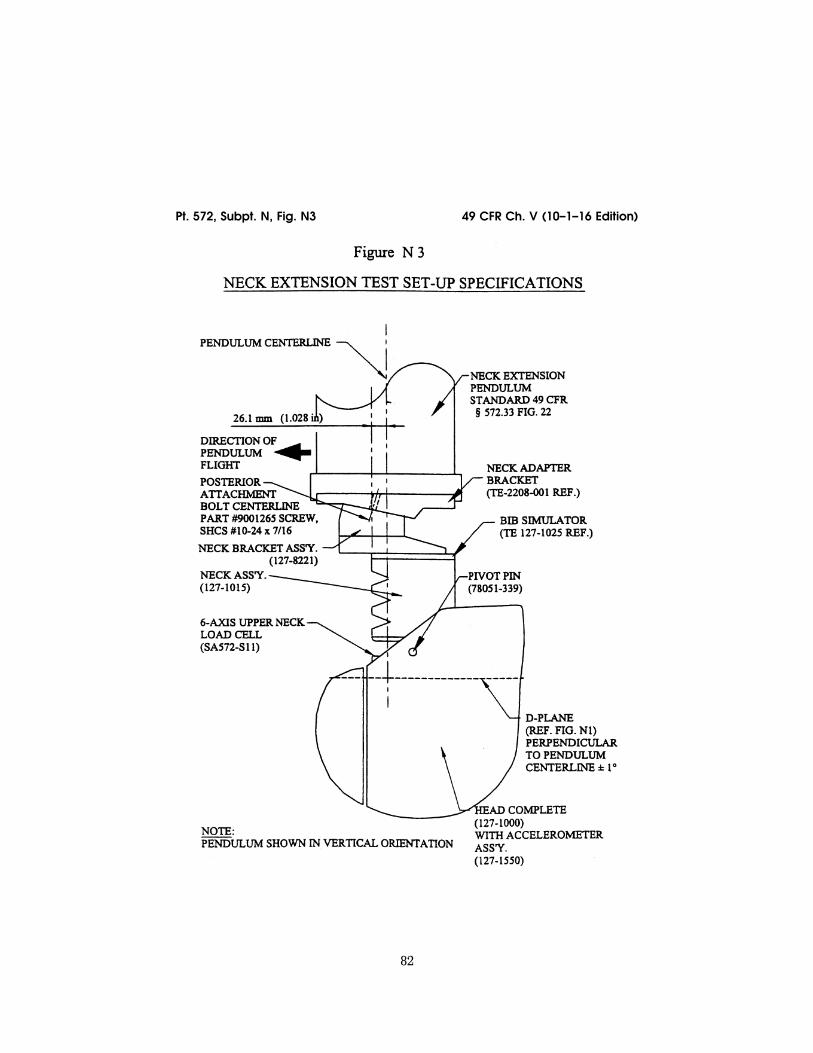
82
49 CFR Ch. V (10–1–16 Edition) Pt. 572, Subpt. N, Fig. N3
VerDate Sep<11>2014 10:23 Mar 06, 2017 Jkt 238231 PO 00000 Frm 00092 Fmt 8010 Sfmt 8006 Y:\SGML\238231.XXX 238231 ER
18JY
02.0
02<
/GP
H>
jsta
llwor
th o
n D
SK
7TP
TV
N1P
RO
D w
ith C
FR

83
Nat’l Highway Traffic Safety Admin., DOT Pt. 572, Subpt. N, Fig. N4
VerDate Sep<11>2014 10:23 Mar 06, 2017 Jkt 238231 PO 00000 Frm 00093 Fmt 8010 Sfmt 8006 Y:\SGML\238231.XXX 238231 ER
13JA
00.0
05<
/GP
H>
jsta
llwor
th o
n D
SK
7TP
TV
N1P
RO
D w
ith C
FR

84
49 CFR Ch. V (10–1–16 Edition) Pt. 572, Subpt. N, Fig. N5
VerDate Sep<11>2014 10:23 Mar 06, 2017 Jkt 238231 PO 00000 Frm 00094 Fmt 8010 Sfmt 8006 Y:\SGML\238231.XXX 238231 ER
19S
E02
.000
</G
PH
>
jsta
llwor
th o
n D
SK
7TP
TV
N1P
RO
D w
ith C
FR

85
Nat’l Highway Traffic Safety Admin., DOT Pt. 572, Subpt. N, Fig. N6
[65 FR 2065, Jan. 13, 2000, as amended at 67 FR 47329, July 18, 2002; 67 FR 59023, Sept. 19, 2002]
VerDate Sep<11>2014 10:23 Mar 06, 2017 Jkt 238231 PO 00000 Frm 00095 Fmt 8010 Sfmt 8026 Y:\SGML\238231.XXX 238231 ER
18JY
02.0
03<
/GP
H>
jsta
llwor
th o
n D
SK
7TP
TV
N1P
RO
D w
ith C
FR

86
49 CFR Ch. V (10–1–16 Edition) § 572.130
Subpart O—Hybrid III 5th Per-centile Female Test Dummy, Alpha Version
SOURCE: 65 FR 10968, Mar. 1, 2000, unless otherwise noted.
§ 572.130 Incorporation by reference. (a) The following materials are here-
by incorporated into this Subpart by reference:
(1) A drawings and specification package entitled ‘‘Parts List and Draw-ings, Part 572 Subpart O Hybrid III Fifth Percentile Small Adult Female Crash Test Dummy (HIII–5F, Alpha Version)’’ (June 2002), incorporated by reference in ‘‘572.131, and consisting of:
(i) Drawing No. 880105–100X, Head As-sembly, incorporated by reference in §§ 572.131, 572.132, 572.133, 572.134, 572.135, and 572.137;
(ii) Drawing No. 880105–250, Neck As-sembly, incorporated by reference in §§ 572.131, 572.133, 572.134, 572.135, and 572.137;
(iii) Drawing No. 880105–300, Upper Torso Assembly, incorporated by ref-erence in §§ 572.131, 572.134, 572.135, and 572.137;
(iv) Drawing No. 880105–450, Lower Torso Assembly, incorporated by ref-erence in §§ 572.131, 572.134, 572.135, and 572.137;
(v) Drawing No. 880105–560–1, Com-plete Leg Assembly—left, incorporated by reference in §§ 572.131, 572.135, 572.136, and 572.137;
(vi) Drawing No. 880105–560–2, Com-plete Leg Assembly—right incor-porated by reference in §§ 572.131, 572.135, 572.136, and 572.137;
(vii) Drawing No. 880105–728–1, Com-plete Arm Assembly—left, incorporated by reference in §§ 572.131, 572.134, and 572.135 as part of the complete dummy assembly;
(viii) Drawing No. 880105–728–2, Com-plete Arm Assembly—right, incor-porated by reference in §§ 572.131, 572.134, and 572.135 as part of the com-plete dummy assembly;
(ix) The Hybrid III 5th percentile small adult female crash test dummy parts list, incorporated by reference in § 572.131;
(2) A procedures manual entitled ‘‘Procedures for Assembly, Dis-assembly, and Inspection (PADI) Sub-
part O Hybrid III Fifth Percentile Adult Female Crash Test Dummy (HIII–5F), Alpha Version’’ (February 2002), incorporated by reference in § 572.132.
(3) SAE Recommended Practice J211/ 1, Rev. Mar 95 ‘‘Instrumentation for Impact Tests—Part 1—Electronic In-strumentation’’, incorporated by ref-erence in § 572.137;
(4) SAE Recommended Practice J211/ 2, Rev. Mar 95 ‘‘Instrumentation for Impact Tests—Part 2—Photographic Instrumentation’’ incorporated by ref-erence in § 572.137; and
(5) SAE J1733 of 1994–12 ‘‘Sign Con-vention for Vehicle Crash Testing’’, in-corporated by reference in § 572.137.
(b) The Director of the Federal Reg-ister approved the materials incor-porated by reference in accordance with 5 U.S.C. 552(a) and 1 CFR part 51. Copies of the materials may be in-spected at NHTSA’s Technical Ref-erence Library, 400 Seventh Street SW., room 5109, Washington, DC, or at the National Archives and Records Ad-ministration (NARA). For information on the availability of this material at NARA, call 202–741–6030, or go to: http:// www.archives.gov/federallregister/ codeloflfederallregulations/ ibrllocations.html.
(c) The incorporated materials are available as follows:
(1) The Parts List and Drawings, Part 572 Subpart O Hybrid III Fifth Per-centile Small Adult Female Crash Test Dummy, (HIII–5F, Alpha Version) (June 2002), referred to in paragraph (a)(1) of this section and the Proce-dures for Assembly, Disassembly, and Inspection (PADI) of the Hybrid III 5th Percentile Small Adult Female Crash Test Dummy, Alpha Version, referred to in paragraph (a)(2) of this section are available from Reprographic Tech-nologies, 9107 Gaither Road, Gaithers-burg, MD 20877, (301) 419–5070. These documents are also accessible for read-ing and copying through the DOT Docket Management System.
(2) The SAE materials referred to in paragraphs (a)(3) and (a)(4) of this sec-tion are available from the Society of
VerDate Sep<11>2014 10:23 Mar 06, 2017 Jkt 238231 PO 00000 Frm 00096 Fmt 8010 Sfmt 8002 Y:\SGML\238231.XXX 238231jsta
llwor
th o
n D
SK
7TP
TV
N1P
RO
D w
ith C
FR

87
Nat’l Highway Traffic Safety Admin., DOT § 572.133
Automotive Engineers, Inc., 400 Com-monwealth Drive, Warrendale, Pa. 15096.
[65 FR 10968, Mar. 1, 2000, as amended at 67 FR 46413, July 15, 2002]
§ 572.131 General description. (a) The Hybrid III fifth percentile
adult female crash test dummy is de-fined by drawings and specifications containing the following materials:
(1) Technical drawings and specifica-tions package P/N 880105–000 (refer to § 572.130(a)(1)), the titles of which are listed in Table A;
(2) Parts List and Drawings, Part 572 Subpart O Hybrid III Fifth Percentile Small Adult Female Crash Test Dummy (HIII–5F, Alpha Version) (June 2002) (refer to § 572.130(a)(1)(ix)).
TABLE A
Component assembly Drawing No.
Head Assembly ....................................... 880105–100X Neck Assembly ........................................ 880105–250 Upper Torso Assembly ............................ 880105–300 Lower Torso Assembly ............................ 880105–450 Complete Leg Assembly—left ................. 880105–560–1 Complete Leg Assembly—right ............... 880105–560–2 Complete Arm Assembly—left ................ 880105–728–1 Complete Arm Assembly—right .............. 880105–728–2
(b) Adjacent segments are joined in a manner such that, except for contacts existing under static conditions, there is no contact between metallic ele-ments throughout the range of motion or under simulated crash impact condi-tions.
(c) The structural properties of the dummy are such that the dummy con-forms to this Subpart in every respect before use in any test similar to those specified in Standard 208, Occupant Crash Protection.
[65 FR 10968, Mar. 1, 2000, as amended at 67 FR 46414, July 15, 2002]
§ 572.132 Head assembly and test pro-cedure.
(a) The head assembly (refer to § 572.130(a)(1)(i)) for this test consists of the complete head (drawing 880105– 100X), a six-axis neck transducer (draw-ing SA572–S11) or its structural re-placement (drawing 78051–383X), and 3 accelerometers (drawing SA572–S4).
(b) When the head assembly is dropped from a height of 376.0 ±1.0 mm
(14.8 ±0.04 in) in accordance with sub-section (c) of this section, the peak re-sultant acceleration at the location of the accelerometers at the head CG may not be less than 250 G or more than 300 G. The resultant acceleration vs. time history curve shall be unimodal; oscil-lations occurring after the main pulse must be less than 10 percent of the peak resultant acceleration. The lat-eral acceleration shall not exceed 15 G (zero to peak).
(c) Head test procedure. The test pro-cedure for the head is as follows:
(1) Soak the head assembly in a con-trolled environment at any tempera-ture between 18.9 and 25.6 °C (66 and 78 °F) and a relative humidity from 10 to 70 percent for at least four hours prior to a test.
(2) Prior to the test, clean the impact surface of the skin and the impact plate surface with isopropyl alcohol, trichloroethane, or an equivalent. The skin of the head must be clean and dry for testing.
(3) Suspend and orient the head as-sembly as shown in Figure 19 of 49 CFR 572. The lowest point on the forehead must be 376.0 ±1.0 mm (14.8 ±0.04 in) from the impact surface. The 1.57 mm (0.062 in) diameter holes located on ei-ther side of the dummy’s head shall be used to ensure that the head is level with respect to the impact surface.
(4) Drop the head assembly from the specified height by means that ensure a smooth, instant release onto a rigidly supported flat horizontal steel plate which is 50.8 mm (2.0 in) thick and 610 mm (24.0 in) square. The impact surface shall be clean, dry and have a micro finish of not less than 203.2. × 10¥6 mm (8 micro inches) (RMS) and not more than 2032.0 × 10¥6 mm (80 micro inches) (RMS).
(5) Allow at least 2 hours between successive tests on the same head.
§ 572.133 Neck assembly and test pro-cedure.
(a) The neck assembly (refer to § 572.130(a)(1)(ii)) for the purposes of this test consists of the assembly of components shown in drawing 880105– 250.
(b) When the head-neck assembly consisting of the head (drawing 880105– 100X), neck (drawing 880105–250), bib
VerDate Sep<11>2014 10:23 Mar 06, 2017 Jkt 238231 PO 00000 Frm 00097 Fmt 8010 Sfmt 8002 Y:\SGML\238231.XXX 238231jsta
llwor
th o
n D
SK
7TP
TV
N1P
RO
D w
ith C
FR
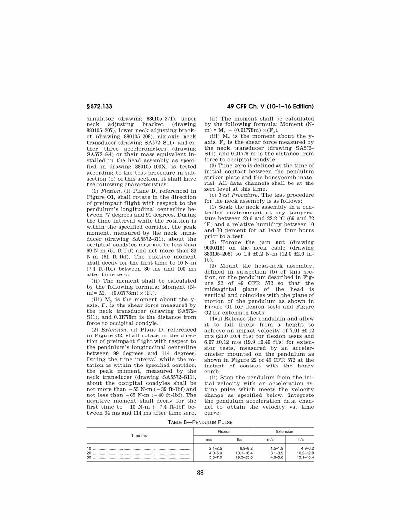
88
49 CFR Ch. V (10–1–16 Edition) § 572.133
simulator (drawing 880105–371), upper neck adjusting bracket (drawing 880105–207), lower neck adjusting brack-et (drawing 880105–208), six-axis neck transducer (drawing SA572–S11), and ei-ther three accelerometers (drawing SA572–S4) or their mass equivalent in-stalled in the head assembly as speci-fied in drawing 880105–100X, is tested according to the test procedure in sub-section (c) of this section, it shall have the following characteristics:
(1) Flexion. (i) Plane D, referenced in Figure O1, shall rotate in the direction of preimpact flight with respect to the pendulum’s longitudinal centerline be-tween 77 degrees and 91 degrees. During the time interval while the rotation is within the specified corridor, the peak moment, measured by the neck trans-ducer (drawing SA5572–311), about the occipital condyles may not be less than 69 N-m (51 ft-lbf) and not more than 83 N-m (61 ft-lbf). The positive moment shall decay for the first time to 10 N-m (7.4 ft-lbf) between 80 ms and 100 ms after time zero.
(ii) The moment shall be calculated by the following formula: Moment (N- m)= My¥(0.01778m) × (Fx).
(iii) My is the moment about the y- axis, Fx is the shear force measured by the neck transducer (drawing SA572– S11), and 0.01778m is the distance from force to occipital condyle.
(2) Extension. (i) Plane D, referenced in Figure O2, shall rotate in the direc-tion of preimpact flight with respect to the pendulum’s longitudinal centerline between 99 degrees and 114 degrees. During the time interval while the ro-tation is within the specified corridor, the peak moment, measured by the neck transducer (drawing SA5572–S11), about the occipital condyles shall be not more than ¥53 N-m (¥39 ft-lbf) and not less than ¥65 N-m (¥48 ft-lbf). The negative moment shall decay for the first time to ¥10 N-m (¥7.4 ft-lbf) be-tween 94 ms and 114 ms after time zero.
(ii) The moment shall be calculated by the following formula: Moment (N- m) = My ¥ (0.01778m) × (Fx).
(iii) My is the moment about the y- axis, Fx is the shear force measured by the neck transducer (drawing SA572– S11), and 0.01778 m is the distance from force to occipital condyle.
(3) Time-zero is defined as the time of initial contact between the pendulum striker plate and the honeycomb mate-rial. All data channels shall be at the zero level at this time.
(c) Test Procedure. The test procedure for the neck assembly is as follows:
(1) Soak the neck assembly in a con-trolled environment at any tempera-ture between 20.6 and 22.2 °C (69 and 72 °F) and a relative humidity between 10 and 70 percent for at least four hours prior to a test.
(2) Torque the jam nut (drawing 9000018) on the neck cable (drawing 880105–206) to 1.4 ±0.2 N-m (12.0 ±2.0 in- lb).
(3) Mount the head-neck assembly, defined in subsection (b) of this sec-tion, on the pendulum described in Fig-ure 22 of 49 CFR 572 so that the midsagittal plane of the head is vertical and coincides with the plane of motion of the pendulum as shown in Figure O1 for flexion tests and Figure O2 for extension tests.
(4)(i) Release the pendulum and allow it to fall freely from a height to achieve an impact velocity of 7.01 ±0.12 m/s (23.0 ±0.4 ft/s) for flexion tests and 6.07 ±0.12 m/s (19.9 ±0.40 ft/s) for exten-sion tests, measured by an acceler-ometer mounted on the pendulum as shown in Figure 22 of 49 CFR 572 at the instant of contact with the honey comb.
(ii) Stop the pendulum from the ini-tial velocity with an acceleration vs. time pulse which meets the velocity change as specified below. Integrate the pendulum acceleration data chan-nel to obtain the velocity vs. time curve:
TABLE B—PENDULUM PULSE
Time ms Flexion Extension
m/s ft/s m/s ft/s
10 .......................................................................................... 2.1–2.5 6.9–8.2 1.5–1.9 4.9–6.2 20 .......................................................................................... 4.0–5.0 13.1–16.4 3.1–3.9 10.2–12.8 30 .......................................................................................... 5.8–7.0 19.5–23.0 4.6–5.6 15.1–18.4
VerDate Sep<11>2014 10:23 Mar 06, 2017 Jkt 238231 PO 00000 Frm 00098 Fmt 8010 Sfmt 8002 Y:\SGML\238231.XXX 238231jsta
llwor
th o
n D
SK
7TP
TV
N1P
RO
D w
ith C
FR

89
Nat’l Highway Traffic Safety Admin., DOT § 572.135
[65 FR 10968, Mar. 1, 2000, as amended at 67 FR 46414, July 15, 2002]
§ 572.134 Thorax assembly and test procedure.
(a) Thorax (Upper Torso) Assembly (refer to § 572.130(a)(1)(iii)). The thorax consists of the part of the torso assem-bly shown in drawing 880105–300.
(b) When the anterior surface of the thorax of a completely assembled dummy (drawing 880105–000) is im-pacted by a test probe conforming to section 572.137(a) at 6.71 ±0.12 m/s (22.0 ±0.4 ft/s) according to the test proce-dure in subsection (c) of this section:
(1) Maximum sternum displacement (compression) relative to the spine, measured with chest deflection trans-ducer (drawing SA572–S5), must be not less than 50.0 mm (1.97 in) and not more than 58.0 mm (2.30 in). Within this spec-ified compression corridor, the peak force, measured by the impact probe as defined in section 572.137 and cal-culated in accordance with paragraph (b)(3) of this section, shall not be less than 3900 N (876 lbf) and not more than 4400 N (989 lbf). The peak force after 18.0 mm (0.71 in) of sternum displace-ment but before reaching the minimum required 50.0 mm (1.97 in) sternum dis-placement limit shall not exceed 4600 N.
(2) The internal hysteresis of the ribcage in each impact as determined by the plot of force vs. deflection in paragraph (1) of this section shall be not less than 69 percent but not more than 85 percent. The hysteresis shall be calculated by determining the ratio of the area between the loading and un-loading portions of the force deflection curve to the area under the loading portion of the curve.
(3) The force shall be calculated by the product of the impactor mass and its deceleration.
(c) Test procedure. The test procedure for the thorax assembly is as follows:
(1) The dummy is clothed in a form fitting cotton stretch above-the-elbow sleeved shirt and above-the-knee pants. The weight of the shirt and pants shall not exceed 0.14 kg (0.30 lb) each.
(2) Soak the dummy in a controlled environment at any temperature be-tween 20.6 and 22.2 °C (69 and 72 °F) and a relative humidity between 10 and 70
percent for at least four hours prior to a test.
(3) Seat and orient the dummy on a seating surface without back support as shown in Figure O3, with the limbs extended horizontally and forward, par-allel to the midsagittal plane, the midsagittal plane vertical within ±1 de-gree and the ribs level in the anterior- posterior and lateral directions within ±0.5 degrees.
(4) Establish the impact point at the chest midsagittal plane so that the im-pact point of the longitudinal center-line of the probe coincides with the midsagittal plane of the dummy within ±2.5 mm (0.1 in) and is 12.7 ±1.1 mm (0.5 ±0.04 in) below the horizontal-periph-eral centerline of the No. 3 rib and is within 0.5 degrees of a horizontal line in the dummy’s midsagittal plane.
(5) Impact the thorax with the test probe so that at the moment of contact the probe’s longitudinal center line falls within 2 degrees of a horizontal line in the dummy’s midsagittal plane.
(6) Guide the test probe during im-pact so that there is no significant lat-eral, vertical or rotational movement.
(7) No suspension hardware, suspen-sion cables, or any other attachments to the probe, including the velocity vane, shall make contact with the dummy during the test.
[65 FR 10968, Mar. 1, 2000, as amended at 67 FR 46415, July 15, 2002]
§ 572.135 Upper and lower torso as-semblies and torso flexion test pro-cedure.
(a) Upper/lower torso assembly. The test objective is to determine the stiff-ness effects of the lumbar spine (draw-ing 880105–1096), and abdominal insert (drawing 880105–434), on resistance to articulation between the upper torso assembly (drawing 880105–300) and the lower torso assembly (drawing 880105– 450) (refer to § 572.130(a)(1)(iv)).
(b)(1) When the upper torso assembly of a seated dummy is subjected to a force continuously applied at the head to neck pivot pin level through a rig-idly attached adaptor bracket as shown in Figure O4 according to the test pro-cedure set out in subsection (c) of this section, the lumbar spine-abdomen as-sembly shall flex by an amount that permits the upper torso assembly to
VerDate Sep<11>2014 10:23 Mar 06, 2017 Jkt 238231 PO 00000 Frm 00099 Fmt 8010 Sfmt 8002 Y:\SGML\238231.XXX 238231jsta
llwor
th o
n D
SK
7TP
TV
N1P
RO
D w
ith C
FR

90
49 CFR Ch. V (10–1–16 Edition) § 572.136
translate in angular motion relative to the vertical transverse plane 45 ±0.5 de-grees at which time the force applied must be not less than 320 N (71.5 lbf) and not more than 390 N (87.4 lbf), and
(2) Upon removal of the force, the torso assembly must return to within 8 degrees of its initial position.
(c) Test procedure. The test procedure for the upper/lower torso assembly is as follows:
(1) Soak the dummy in a controlled environment at any temperature be-tween 18.9 and 25.6 °C (66 and 78 °F) and a relative humidity between 10 and 70 percent for at least four hours prior to a test.
(2) Assemble the complete dummy (with or without the legs below the fe-murs) and attach to the fixture in a seated posture as shown in Figure O4.
(3) Secure the pelvis to the fixture at the pelvis instrument cavity rear face by threading four 1⁄4 inch cap screws into the available threaded attachment holes. Tighten the mountings so that the test material is rigidly affixed to the test fixture and the pelvic-lumbar joining surface is horizontal.
(4) Attach the loading adapter brack-et to the spine of the dummy as shown in Figure O4.
(5) Inspect and adjust, if necessary, the seating of the abdominal insert within the pelvis cavity and with re-spect to the torso flesh, assuring that the torso flesh provides uniform fit and overlap with respect to the outside sur-face of the pelvis flesh.
(6) Flex the dummy’s upper torso three times between the vertical and until the torso reference plane, as shown in Figure O4, reaches 30 degrees from the vertical transverse plane. Bring the torso to vertical orientation and wait for 30 minutes before con-ducting the test. During the 30 minute waiting period, the dummy’s upper torso shall be externally supported at or near its vertical orientation to pre-vent it from drooping.
(7) Remove all external support and wait two minutes. Measure the initial orientation angle of the torso reference plane of the seated, unsupported dummy as shown in Figure O4. The ini-tial orientation angle may not exceed 20 degrees.
(8) Attach the pull cable and the load cell as shown in Figure O4.
(9) Apply a tension force in the midsagittal plane to the pull cable as shown in Figure O4 at any upper torso deflection rate between 0.5 and 1.5 de-grees per second, until the angle ref-erence plane is at 45 ±0.5 degrees of flexion relative to the vertical trans-verse plane.
(9) Continue to apply a force suffi-cient to maintain 45 ±0.5 degrees of flexion for 10 seconds, and record the highest applied force during the 10-sec-ond period.
(10) Release all force at the attach-ment bracket as rapidly as possible, and measure the return angle with re-spect to the initial angle reference plane as defined in paragraph (6) 3 min-utes after the release.
§ 572.136 Knees and knee impact test procedure.
(a) Knee assembly. The knee assembly (refer to §§ 572.130(a)(1)(v) and (vi)) for the purpose of this test is the part of the leg assembly shown in drawing 880105–560.
(b)(1) When the knee assembly, con-sisting of sliding knee assembly (draw-ing 880105–528R or –528L), lower leg structural replacement (drawing 880105–603), lower leg flesh (drawing 880105–601), ankle assembly (drawing 880105–660), foot assembly (drawing 880105–651 or 650), and femur load trans-ducer (drawing SA572–S14) or its struc-tural replacement (drawing 78051–319) is tested according to the test procedure in subsection (c), the peak resistance force as measured with the test probe- mounted accelerometer must be not less than 3450 N (776 lbf) and not more than 4060 N (913 lbf).
(2) The force shall be calculated by the product of the impactor mass and its deceleration.
(c) Test procedure. The test procedure for the knee assembly is as follows:
(1) Soak the knee assembly in a con-trolled environment at any tempera-ture between 18.9 and 25.6 °C (66 and 78 °F) and a relative humidity from 10 to 70 percent for at least four hours prior to a test.
(2) Mount the test material and se-cure it to a rigid test fixture as shown
VerDate Sep<11>2014 10:23 Mar 06, 2017 Jkt 238231 PO 00000 Frm 00100 Fmt 8010 Sfmt 8002 Y:\SGML\238231.XXX 238231jsta
llwor
th o
n D
SK
7TP
TV
N1P
RO
D w
ith C
FR

91
Nat’l Highway Traffic Safety Admin., DOT § 572.137
in Figure O5. No part of the foot or tibia may contact any exterior surface.
(3) Align the test probe so that throughout its stroke and at contact with the knee it is within 2 degrees of horizontal and collinear with the longi-tudinal centerline of the femur.
(4) Guide the pendulum so that there is no significant lateral vertical or ro-tational movement at the time of ini-tial contact between the impactor and the knee.
(5) The test probe velocity at the time of contact shall be 2.1 ±0.03 m/s (6.9 ±0.1 ft/s).
(6) No suspension hardware, suspen-sion cables, or any other attachments to the probe, including the velocity vane, shall make contact with the dummy during the test.
[65 FR 10968, Mar. 1, 2000, as amended at 67 FR 46415, July 15, 2002]
§ 572.137 Test conditions and instru-mentation.
(a) The test probe for thoracic im-pacts, except for attachments, shall be of rigid metallic construction and con-centric about its longitudinal axis. Any attachments to the impactor, such as suspension hardware, impact vanes, etc., must meet the requirements of § 572.134(c)(7). The impactor shall have a mass of 13.97 ±0.23 kg (30.8 ±0.5 lbs) and a minimum mass moment of iner-tia of 3646 kg-cm2 (3.22 lbs-in-sec2) in yaw and pitch about the CG of the probe. One-third (1/3) of the weight of suspension cables and any attachments to the impact probe must be included in the calculation of mass, and such components may not exceed five per-cent of the total weight of the test probe. The impacting end of the probe, perpendicular to and concentric with the longitudinal axis of the probe, has a flat, continuous, and non-deformable 152.4 ±0.25 mm (6.00 ±0.01 in) diameter face with a minimum/maximum edge radius of 7.6/12.7 mm (0.3/0.5 in). The impactor shall have a 152.4–152.6 mm (6.0–6.1 in) diameter cylindrical surface extending for a minimum of 25 mm (1.0 in) to the rear from the impact face. The probe’s end opposite to the impact face has provisions for mounting of an accelerometer with its sensitive axis collinear with the longitudinal axis of the probe. The impact probe has a free
air resonant frequency of not less than 1000 Hz, which may be determined using the procedure listed in Docket No. NHTSA–6714–14.
(b) The test probe for knee impacts, except for attachments, shall be of rigid metallic construction and concen-tric about its longitudinal axis. Any attachments to the impactor, such as suspension hardware, impact vanes, etc., must meet the requirements of § 572.136(c)(6). The impactor shall have a mass of 2.99±0.23 kg (6.6±0.5 lbs) and a minimum mass moment of inertia of 209 kg-cm2 (0.177 lb-in-sec2) in yaw and pitch about the CG of the probe. One- third (1/3) of the weight of suspension cables and any attachments to the im-pact probe may be included in the cal-culation of mass, and such components may not exceed five percent of the total weight of the test probe. The im-pacting end of the probe, perpendicular to and concentric with the longitudinal axis of the probe, has a flat, contin-uous, and non-deformable 76.2 ±0.2 mm (3.00 ±0.01 in) diameter face with a min-imum/maximum edge radius of 7.6/12.7 mm (0.3/0.5 in). The impactor shall have a 76.2–76.4 mm (3.0–3.1 in) diameter cy-lindrical surface extending for a min-imum of 12.5 mm (0.5 in) to the rear from the impact face. The probe’s end opposite to the impact face has provi-sions for mounting an accelerometer with its sensitive axis collinear with the longitudinal axis of the probe. The impact probe has a free air resonant frequency of not less than 1000 Hz, which may be determined using the procedure listed in Docket No. NHTSA– 6714–14.
(c) Head accelerometers shall have dimensions, response characteristics, and sensitive mass locations specified in drawing SA572–S4 and be mounted in the head as shown in drawing 880105–000 sheet 3 of 6.
(d) The upper neck force/moment transducer shall have the dimensions, response characteristics, and sensitive axis locations specified in drawing SA572–S11 and be mounted in the head neck assembly as shown in drawing 880105–000, sheet 3 of 6.
(e) The thorax accelerometers shall have the dimensions, response charac-teristics, and sensitive mass locations specified in drawing SA572–S4 and be
VerDate Sep<11>2014 10:23 Mar 06, 2017 Jkt 238231 PO 00000 Frm 00101 Fmt 8010 Sfmt 8002 Y:\SGML\238231.XXX 238231jsta
llwor
th o
n D
SK
7TP
TV
N1P
RO
D w
ith C
FR

92
49 CFR Ch. V (10–1–16 Edition) § 572.137
mounted in the torso assembly in tri-axial configuration within the spine box instrumentation cavity and as op-tional instrumentation in uniaxial for- and-aft oriented configuration ar-ranged as corresponding pairs in three locations on the sternum on and at the spine box of the upper torso assembly as shown in drawing 880105–000 sheet 3 of 6.
(f) The optional lumbar spine force- moment transducer shall have the di-mensions, response characteristics, and sensitive axis locations specified in drawing SA572–S15 and be mounted in the lower torso assembly as shown in drawing 880105–450.
(g) The optional iliac spine force transducers shall have the dimensions and response characteristics specified in drawing SA572–S16 and be mounted in the torso assembly as shown in drawing 880105–450.
(h) The pelvis accelerometers shall have the dimensions, response charac-teristics, and sensitive mass locations specified in drawing SA572–S4 and be mounted in the torso assembly in tri-axial configuration in the pelvis bone as shown in drawing 880105–000 sheet 3.
(i) The single axis femur force trans-ducer (SA572–S14) or the optional mul-tiple axis femur force/moment trans-ducer (SA572–S29) shall have the di-mensions, response characteristics, and sensitive axis locations specified in the appropriate drawing and be mounted in the femur assembly as shown in draw-ing 880105–500 sheet 3 of 6.
(j) The chest deflection transducer shall have the dimensions and response characteristics specified in drawing SA572–S51 and be mounted to the upper torso assembly as shown in drawings 880105–300 and 880105–000 sheet 3 of 6.
(k) The optional lower neck force/mo-ment transducer shall have the dimen-sions, response characteristics, and sensitive axis locations specified in drawing SA572–S27 and be mounted to the upper torso assembly as shown in drawing 880105–000 sheet 3 of 6.
(l) The optional thoracic spine force/ moment transducer shall have the di-mensions, response characteristics, and sensitive axis locations specified in drawing SA572–S28 and be mounted in the upper torso assembly as shown in drawing 880105–000 sheet 3 of 6.
(m) The outputs of acceleration and force-sensing devices installed in the dummy and in the test apparatus speci-fied by this part shall be recorded in in-dividual data channels that conform to SAE Recommended Practice J211/10, Rev. Mar95 ‘‘Instrumentation for Im-pact Impact Tests;—Part 1—Electronic Instrumentation,’’ and SAE Rec-ommended Practice J211/2, Rev Mar95 ‘‘Instrumentation for Impact Tests— Part 2—Photographic Instrumenta-tion’’, (refer to §§ 572.130(a)(3) and (4) re-spectively) except as noted, with chan-nel classes as follows:
(1) Head acceleration—Class 1000 (2) Neck: (i) Forces—Class 1000 (ii) Moments—Class 600 (iii) Pendulum acceleration—Class
180 (iv) Rotation potentiometer—Class 60
(optional) (3) Thorax: (i) Rib acceleration—Class 1000 (ii) Spine and pendulum accelera-
tions—Class 180 (iii) Sternum deflection—Class 600 (iv) Forces—Class 1000 (v) Moments—Class 600 (4) Lumbar: (i) Forces—Class 1000 (ii) Moments—Class 600 (iii) Torso flexion pulling force—
Class 60 if data channel is used (5) Pelvis: (i) Accelerations—Class 1000 (ii) Iliac wing forces—Class 180 (6) Femur forces and knee pen-
dulum—Class 600 (n) Coordinate signs for instrumenta-
tion polarity shall conform to the Sign Convention For Vehicle Crash Testing, Surface Vehicle Information Report, SAE J1733, 1994–12 (refer to section 572.130(a)(4)).
(o) The mountings for sensing devices shall have no resonance frequency less than 3 times the frequency range of the applicable channel class.
(p) Limb joints must be set at one G, barely restraining the weight of the limb when it is extended horizontally. The force needed to move a limb seg-ment shall not exceed 2G throughout the range of limb motion.
(q) Performance tests of the same component, segment, assembly, or
VerDate Sep<11>2014 10:23 Mar 06, 2017 Jkt 238231 PO 00000 Frm 00102 Fmt 8010 Sfmt 8002 Y:\SGML\238231.XXX 238231jsta
llwor
th o
n D
SK
7TP
TV
N1P
RO
D w
ith C
FR

93
Nat’l Highway Traffic Safety Admin., DOT § 572.137
fully assembled dummy shall be sepa-rated in time by not less than 30 min-utes unless otherwise noted.
(r) Surfaces of dummy components may not be painted except as specified
in this subpart or in drawings sub-tended by this subpart.
[65 FR 10968, Mar. 1, 2000, as amended at 67 FR 46415, July 15, 2002; 74 FR 29894, June 23, 2009]
VerDate Sep<11>2014 10:23 Mar 06, 2017 Jkt 238231 PO 00000 Frm 00103 Fmt 8010 Sfmt 8002 Y:\SGML\238231.XXX 238231jsta
llwor
th o
n D
SK
7TP
TV
N1P
RO
D w
ith C
FR

94
49 CFR Ch. V (10–1–16 Edition) Pt. 572, Subpt. O, Fig. 01
FIGURES TO SUBPART O OF PART 572
VerDate Sep<11>2014 10:23 Mar 06, 2017 Jkt 238231 PO 00000 Frm 00104 Fmt 8010 Sfmt 8006 Y:\SGML\238231.XXX 238231 ER
15JY
02.0
00<
/GP
H>
jsta
llwor
th o
n D
SK
7TP
TV
N1P
RO
D w
ith C
FR

95
Nat’l Highway Traffic Safety Admin., DOT Pt. 572, Subpt. O, Fig. O2
VerDate Sep<11>2014 10:23 Mar 06, 2017 Jkt 238231 PO 00000 Frm 00105 Fmt 8010 Sfmt 8006 Y:\SGML\238231.XXX 238231 ER
15JY
02.0
01<
/GP
H>
jsta
llwor
th o
n D
SK
7TP
TV
N1P
RO
D w
ith C
FR

96
49 CFR Ch. V (10–1–16 Edition) Pt. 572, Subpt. O, Fig. O3
VerDate Sep<11>2014 10:23 Mar 06, 2017 Jkt 238231 PO 00000 Frm 00106 Fmt 8010 Sfmt 8006 Y:\SGML\238231.XXX 238231 ER
15JY
02.0
02<
/GP
H>
jsta
llwor
th o
n D
SK
7TP
TV
N1P
RO
D w
ith C
FR

97
Nat’l Highway Traffic Safety Admin., DOT Pt. 572, Subpt. O, Fig. O4
VerDate Sep<11>2014 10:23 Mar 06, 2017 Jkt 238231 PO 00000 Frm 00107 Fmt 8010 Sfmt 8006 Y:\SGML\238231.XXX 238231 ER
15jy
02.0
03<
/GP
H>
jsta
llwor
th o
n D
SK
7TP
TV
N1P
RO
D w
ith C
FR

98
49 CFR Ch. V (10–1–16 Edition) Pt. 572, Subpt. O, Fig. O5
[65 FR 10968, Mar. 1, 2000, as amended at 67 FR 46415, July 15, 2002]
VerDate Sep<11>2014 10:23 Mar 06, 2017 Jkt 238231 PO 00000 Frm 00108 Fmt 8010 Sfmt 8026 Y:\SGML\238231.XXX 238231 ER
15JY
02.0
04<
/GP
H>
jsta
llwor
th o
n D
SK
7TP
TV
N1P
RO
D w
ith C
FR

99
Nat’l Highway Traffic Safety Admin., DOT § 572.141
Subpart P—3-year-Old Child Crash Test Dummy, Alpha Version
SOURCE: 65 FR 15262, Mar. 22, 2000, unless otherwise noted.
§ 572.140 Incorporation by reference. (a) The following materials are here-
by incorporated in this subpart P by reference:
(1) A drawings and specifications package entitled, ‘‘Parts List and Drawings, Subpart P Hybrid III 3-year- old child crash test dummy, (H-III3C, Alpha version) September 2001,’’ incor-porated by reference in § 572.141 and consisting of:
(i) Drawing No. 210–1000, Head Assem-bly, incorporated by reference in §§ 572.141, 572.142, 572.144, 572.145, and 572.146;
(ii) Drawing No. 210–2001, Neck As-sembly, incorporated by reference in §§ 572.141, 572.143, 572.144, 572.145, and 572.146;
(iii) Drawing No. TE–208–000, Headform, incorporated by reference in §§ 572.141, and 572.143;
(iv) Drawing No. 210–3000, Upper/ Lower Torso Assembly, incorporated by reference in §§ 572.141, 572.144, 572.145, and 572.146;
(v) Drawing No. 210–5000–1(L), –2(R), Leg Assembly, incorporated by ref-erence in §§ 572.141, 572.144, 572.145 as part of a complete dummy assembly;
(vi) Drawing No. 210–6000–1(L), –2(R), Arm Assembly, incorporated by ref-erence in §§ 572.141, 572.144, and 572.145 as part of the complete dummy assem-bly;
(2) A procedures manual entitled ‘‘Procedures for Assembly, Dis-assembly and Inspection (PADI), Sub-part P, Hybird III 3-year-old Child Crash Test Dummy, (H-III3C, Alpha Version) September 2001,’’ incorporated by reference in § 572.141;
(3) SAE Recommended Practice J211/ 1, Rev. Mar 95 ‘‘Instrumentation for Impact Tests—Part 1-Electronic In-strumentation’’, incorporated by ref-erence in § 572.146;
(4) SAE J1733 1994–12 ‘‘Sign Conven-tion for Vehicle Crash Testing’’ incor-porated by reference in § 572.146.
(5) The Director of the Federal Reg-ister approved those materials incor-porated by reference in accordance
with 5 U.S.C. 552(a) and 1 CFR Part 51. Copies of the materials may be in-spected at NHTSA’s Docket Section, 400 Seventh Street SW, room 5109, Washington, DC, or at the National Ar-chives and Records Administration (NARA). For information on the avail-ability of this material at NARA, call 202–741–6030, or go to: http:// www.archives.gov/federallregister/ codeloflfederallregulations/ ibrllocations.html.
(b) The incorporated materials are available as follows:
(1) The drawings and specifications package referred to in paragraph (a)(1) of this section and the PADI document referred to in paragraph (a)(2) of this section are accessible for viewing and copying at the Department of Trans-portation’s Docket public area, Plaza 401, 400 Seventh St., SW., Washington, DC 20590, and downloadable at dms.dot.gov. They are also available from Reprographic Technologies, 9107 Gaither Rd., Gaithersburg, MD 20877, (301) 419–5070.
(2) The SAE materials referred to in paragraphs (a)(3) and (a)(4) of this sec-tion are available from the Society of Automotive Engineers, Inc., 400 Com-monwealth Drive, Warrendale, PA 15096.
[65 FR 15262, Mar. 22, 2000, as amended at 66 FR 64376, Dec. 13, 2001]
§ 572.141 General description.
(a) The Hybrid III 3-year-old child dummy is described by the following materials:
(1) Technical drawings and specifica-tions package 210–0000 (refer to § 572.140(a)(1)), the titles of which are listed in Table A of this section;
(2) Procedures for Assembly, Dis-assembly and Inspection document (PADI) (refer to § 572.140(a)(2)).
(b) The dummy is made up of the component assemblies set out in the following Table A of this section:
TABLE A
Component assembly Drawing No.
Head Assembly ....................................... 210–1000 Neck Assembly (complete) ...................... 210–2001 Upper/Lower Torso Assembly ................. 210–3000 Leg Assembly .......................................... 210–5000–1(L),
–2(R)
VerDate Sep<11>2014 10:23 Mar 06, 2017 Jkt 238231 PO 00000 Frm 00109 Fmt 8010 Sfmt 8002 Y:\SGML\238231.XXX 238231jsta
llwor
th o
n D
SK
7TP
TV
N1P
RO
D w
ith C
FR

100
49 CFR Ch. V (10–1–16 Edition) § 572.142
TABLE A—Continued
Component assembly Drawing No.
Arm Assembly ......................................... 210–6000–1(L), –2(R)
(c) Adjacent segments are joined in a manner such that except for contacts existing under static conditions, there is no contact between metallic ele-ments throughout the range of motion or under simulated crash impact condi-tions.
(d) The structural properties of the dummy are such that the dummy con-forms to this part in every respect only before use in any test similar to those specified in Standard 208, Occupant Crash Protection, and Standard 213, Child Restraint Systems.
§ 572.142 Head assembly and test pro-cedure.
(a) The head assembly (refer to § 572.140(a)(1)(i)) for this test consists of the head (drawing 210–1000), adapter plate (drawing ATD 6259), acceler-ometer mounting block (drawing SA 572–S80), structural replacement of 1⁄2 mass of the neck load transducer (drawing TE–107–001), head mounting washer (drawing ATD 6262), one 1⁄2–20 × 1″ flat head cap screw (FHCS) (drawing 9000150), and 3 accelerometers (drawing SA–572–S4).
(b) When the head assembly in para-graph (a) of this section is dropped from a height of 376.0±1.0 mm (14.8±0.04 in) in accordance with paragraph (c) of this section, the peak resultant accel-eration at the location of the accelerometers at the head CG shall not be less than 250 g or more than 280 g. The resultant acceleration versus time history curve shall be unimodal, and the oscillations occurring after the main pulse shall be less than 10 percent of the peak resultant acceleration. The lateral acceleration shall not exceed ±15 G (zero to peak).
(c) Head test procedure. The test pro-cedure for the head is as follows:
(1) Soak the head assembly in a con-trolled environment at any tempera-ture between 18.9 and 25.6 °C (66 and 78 °F) and at any relative humidity be-tween 10 and 70 percent for at least four hours prior to a test.
(2) Prior to the test, clean the impact surface of the head skin and the steel impact plate surface with isopropyl al-cohol, trichlorethane, or an equivalent. Both impact surfaces must be clean and dry for testing.
(3) Suspend the head assembly with its midsagittal plane in vertical ori-entation as shown in Figure P1 of this subpart. The lowest point on the fore-head is 376.0 ±1.0 mm (14.76 ±0.04 in) from the steel impact surface. The 3.3 mm (0.13 in) diameter holes, located on either side of the dummy’s head in transverse alignment with the CG, shall be used to ensure that the head transverse plane is level with respect to the impact surface.
(4) Drop the head assembly from the specified height by a means that en-sures a smooth, instant release onto a rigidly supported flat horizontal steel plate which is 50.8 mm (2 in) thick and 610 mm (24 in) square. The impact sur-face shall be clean, dry and have a fin-ish of not less than 203.2 × 10¥6 mm (8 micro inches) (RMS) and not more than 2032.0 × 10¥6 mm (80 micro inches) (RMS).
(5) Allow at least 2 hours between successive tests on the same head.
§ 572.143 Neck-headform assembly and test procedure.
(a) The neck and headform assembly (refer to §§ 572.140(a)(1)(ii) and 572.140(a)(1)(iii)) for the purposes of this test, as shown in Figures P2 and P3 of this subpart, consists of the neck mold-ed assembly (drawing 210–2015), neck cable (drawing 210–2040), nylon shoulder bushing (drawing 9001373), upper mount plate insert (drawing 910420–048), bib simulator (drawing TE–208–050), ure-thane washer (drawing 210–2050), neck mounting plate (drawing TE–250–021), two jam nuts (drawing 9001336), load- moment transducer (drawing SA 572– S19), and headform (drawing TE–208– 000).
(b) When the neck and headform as-sembly, as defined in § 572.143(a), is tested according to the test procedure in paragraph (c) of this section, it shall have the following characteristics:
(1) Flexion.
VerDate Sep<11>2014 10:23 Mar 06, 2017 Jkt 238231 PO 00000 Frm 00110 Fmt 8010 Sfmt 8002 Y:\SGML\238231.XXX 238231jsta
llwor
th o
n D
SK
7TP
TV
N1P
RO
D w
ith C
FR

101
Nat’l Highway Traffic Safety Admin., DOT § 572.144
(i) Plane D, referenced in Figure P2 of this subpart, shall rotate in the di-rection of preimpact flight with re-spect to the pendulum’s longitudinal centerline between 70 degrees and 82 degrees. Within this specified rotation corridor, the peak moment about the occipital condyle may not be less than 42 N-m and not more than 53 N-m.
(ii) The positive moment shall decay for the first time to 10 N-m between 60 ms and 80 ms after time zero.
(iii) The moment and rotation data channels are defined to be zero when the longitudinal centerline of the neck and pendulum are parallel.
(2) Extension. (i) Plane D referenced in Figure P3 of
this subpart shall rotate in the direc-tion of preimpact flight with respect to the pendulum’s longitudinal centerline between 83 degrees and 93 degrees. Within this specified rotation corridor, the peak moment about the occipital condyle may be not more than ¥43.7 N- m and not less than ¥53.3 N-m.
(ii) The negative moment shall decay for the first time to ¥10 N-m between 60 and 80 ms after time zero.
(iii) The moment and rotation data channels are defined to be zero when the longitudinal centerline of the neck and pendulum are parallel.
(c) Test procedure. (1) Soak the neck assembly in a controlled environment at any temperature between 20.6 and 22.2 °C (69 and 72 F) and a relative hu-
midity between 10 and 70 percent for at least four hours prior to a test.
(2) Torque the jam nut (drawing 9001336) on the neck cable (drawing 210– 2040) between 0.2 N-m and 0.3 N-m.
(3) Mount the neck-headform assem-bly, defined in paragraph (a) of this section, on the pendulum so the midsagittal plane of the headform is vertical and coincides with the plane of motion of the pendulum as shown in Figure P2 of this subpart for flexion and Figure P3 of this subpart for exten-sion tests.
(4) Release the pendulum and allow it to fall freely to achieve an impact ve-locity of 5.50 ±0.10 m/s (18.05 + 0.40 ft/s) for flexion and 3.65 ±0.1 m/s (11.98 ±0.40 ft/s) for extension tests, measured by an accelerometer mounted on the pen-dulum as shown in Figure 22 of this part 572 at time zero.
(i) The test shall be conducted with-out inducing any torsion twisting of the neck.
(ii) Stop the pendulum from the ini-tial velocity with an acceleration vs. time pulse which meets the velocity change as specified in Table B of this section. Integrate the pendulum accel-eration data channel to obtain the ve-locity vs. time curve as indicated in Table B of this section.
(iii) Time-zero is defined as the time of initial contact between the pen-dulum striker plate and the honeycomb material. The pendulum data channel shall be zero at this time.
TABLE B—PENDULUM PULSE
Time Flexion Time Extension
ms m/s ft/s ms m/s ft/s
10 .................................................................................. 2.0–2.7 6.6–8.9 6 1.0–1.4 3.3–4.6 15 .................................................................................. 3.0–4.0 9.8–13.1 10 1.9–2.5 6.2–8.2 20 .................................................................................. 4.0–5.1 13.1–16.7 14 2.8–3.5 9.2–11.5
§ 572.144 Thorax assembly and test procedure.
(a) Thorax (upper torso) assembly (refer to § 572.140(a)(1)(iv)). The thorax con-sists of the upper part of the torso as-sembly shown in drawing 210–3000.
(b) When the anterior surface of the thorax of a completely assembled dummy (drawing 210–0000) is impacted by a test probe conforming to
§ 572.146(a) at 6.0 ±0.1 m/s (19.7 ±0.3 ft/s) according to the test procedure in paragraph (c) of this section.
(1) Maximum sternum displacement (compression) relative to the spine, measured with the chest deflection transducer (SA–572–S50), must not be less than 32mm (1.3 in) and not more than 38mm (1.5 in). Within this speci-fied compression corridor, the peak force, measured by the probe-mounted
VerDate Sep<11>2014 10:23 Mar 06, 2017 Jkt 238231 PO 00000 Frm 00111 Fmt 8010 Sfmt 8002 Y:\SGML\238231.XXX 238231jsta
llwor
th o
n D
SK
7TP
TV
N1P
RO
D w
ith C
FR

102
49 CFR Ch. V (10–1–16 Edition) § 572.145
accelerometer as defined in § 572.146(a) and calculated in accordance with paragraph (b)(3) of this section, shall be not less than 680 N and not more than 810 N. The peak force after 12.5 mm of sternum compression but before reach-ing the minimum required 32.0 mm sternum compression shall not exceed 910 N.
(2) The internal hysteresis of the ribcage in each impact, as determined from the force vs. deflection curve, shall be not less than 65 percent and not more than 85 percent. The hysteresis shall be calculated by deter-mining the ratio of the area between the loading and unloading portions of the force deflection curve to the area under the loading portion of the curve.
(3) The force shall be calculated by the product of the impactor mass and its deceleration.
(c) Test procedure. The test procedure for the thorax assembly is as follows:
(1) The test dummy is clothed in cot-ton-polyester-based tight-fitting shirt with long sleeves and ankle-length pants whose combined weight is not more than 0.25 kg (0.55 lbs).
(2) Soak the dummy in a controlled environment at any temperature be-tween 20.6 and 22.2 °C (69 and 72 °F) and at any relative humidity between 10 and 70 percent for at least four hours prior to a test.
(3) Seat and orient the dummy on a seating surface without back support as shown in Figure P4, with the lower limbs extended horizontally and for-ward, the upper arms parallel to the torso and the lower arms extended horizontally and forward, parallel to the midsagittal plane, the midsagittal plane being vertical within ±1 degree and the ribs level in the anterior-pos-terior and lateral directions within ±0.5 degrees.
(4) Establish the impact point at the chest midsagittal plane so that the im-pact point of the longitudinal center-line of the probe coincides with the dummy’s mid-sagittal plane and is cen-tered on the center of No. 2 rib within ±2.5 mm (0.1 in.) and 0.5 degrees of a horizontal plane.
(5) Impact the thorax with the test probe so that at the moment of contact the probe’s longitudinal center line is
within 2 degrees of a horizontal line in the dummy’s midsagittal plane.
(6) Guide the test probe during im-pact so that there is no significant lat-eral, vertical or rotational movement.
(7) No suspension hardware, suspen-sion cables, or any other attachments to the probe, including the velocity vane, shall make contact with the dummy during the test.
[65 FR 15262, Mar. 22, 2000, as amended at 66 FR 64376, Dec. 13, 2001]
§ 572.145 Upper and lower torso as-semblies and torso flexion test pro-cedure.
(a) The test objective is to determine the resistance of the lumbar spine and abdomen of a fully assembled dummy (drawing 210–0000) to flexion articula-tion between upper and lower halves of the torso assembly (refer to § 572.140(a)(1)(iv)).
(b)(1) When the upper half of the torso assembly of a seated dummy is subjected to a force continuously ap-plied at the occipital condyle level through the rigidly attached adaptor bracket in accordance with the test procedure set out in paragraph (c) of this section, the lumbar spine-abdomen assembly shall flex by an amount that permits the upper half of the torso, as measured at the posterior surface of the torso reference plane shown in Fig-ure P5 of this subpart, to translate in angular motion in the midsagittal plane 45 ±0.5 degrees relative to the vertical transverse plane, at which time the pulling force applied must not be less than 130 N (28.8 lbf) and not more than 180 N (41.2 lbf), and
(2) Upon removal of the force, the upper torso assembly returns to within 10 degrees of its initial position.
(c) Test procedure. The test procedure is as follows:
(1) Soak the dummy in a controlled environment at any temperature be-tween 18.9° and 25.6 °C (66 and 78 °F) and at any relative humidity between 10 and 70 percent for at least 4 hours prior to a test.
(2) Assemble the complete dummy (with or without the lower legs) and seat it on a rigid flat-surface table, as shown in Figure P5 of this subpart.
(i) Unzip the torso jacket and remove the four 1⁄4–20 × 3⁄4″ bolts which attach
VerDate Sep<11>2014 10:23 Mar 06, 2017 Jkt 238231 PO 00000 Frm 00112 Fmt 8010 Sfmt 8002 Y:\SGML\238231.XXX 238231jsta
llwor
th o
n D
SK
7TP
TV
N1P
RO
D w
ith C
FR

103
Nat’l Highway Traffic Safety Admin., DOT § 572.146
the lumbar load transducer or its structural replacement to the pelvis weldment (drawing 210–4510) as shown in Figure P5 of this subpart.
(ii) Position the matching end of the rigid pelvis attachment fixture around the lumbar spine and align it over the four bolt holes.
(iii) Secure the fixture to the dummy with the four 1⁄4–20 × 3⁄4″ bolts and at-tach the fixture to the table. Tighten the mountings so that the pelvis-lum-bar joining surface is horizontal within ±1 deg and the buttocks and upper legs of the seated dummy are in contact with the test surface.
(iv) Attach the loading adapter bracket to the upper part of the torso as shown in Figure P5 of this subpart and zip up the torso jacket.
(v) Point the upper arms vertically downward and the lower arms forward.
(3)(i) Flex the thorax forward three times from vertical until the torso ref-erence plane reaches 30 ±2 degrees from vertical. The torso reference plane, as shown in figure P5 of this subpart, is defined by the transverse plane tangent to the posterior surface of the upper backplate of the spine box weldment (drawing 210–8020).
(ii) Remove all externally applied flexion forces and support the upper torso half in a vertical orientation for 30 minutes to prevent it from drooping.
(4) Remove the external support and after two minutes measure the initial orientation angle of the upper torso reference plane of the seated, unsup-ported dummy as shown in Figure P5 of this subpart. The initial orientation of the torso reference plane may not ex-ceed 15 degrees.
(5) Attach the pull cable at the point of load application on the adaptor bracket while maintaining the initial torso orientation. Apply a pulling force in the midsagittal plane, as shown in Figure P5 of this subpart, at any upper torso flexion rate between 0.5 and 1.5 degrees per second, until the torso ref-erence plane reaches 45 ±0.5 degrees of flexion relative to the vertical trans-verse plane.
(6) Continue to apply a force suffi-cient to maintain 45 ±0.5 degrees of flexion for 10 seconds, and record the highest applied force during the 10-sec-ond period.
(7) [Reserved] (8) Release all force at the loading
adaptor bracket as rapidly as possible and measure the return angle with re-spect to the initial angle reference plane as defined in paragraph (c)(4) of this section 3 to 4 minutes after the re-lease.
§ 572.146 Test conditions and instru-mentation.
(a) The test probe for thoracic im-pacts, except for attachments, shall be of rigid metallic construction and con-centric about its longitudinal axis. Any attachments to the impactor such as suspension hardware, and impact vanes, must meet the requirements of § 572.144(c)(7) of this part. The impactor shall have a mass of 1.70 ±0.02 kg (3.75 ±0.05 lb) and a minimum mass moment of inertia 164 kg-cm2 (0.145 lb-in-sec2) in yaw and pitch about the CG of the probe. One-third (1⁄3) of the weight of suspension cables and any attachments to the impact probe must be included in the calculation of mass, and such components may not exceed five per-cent of the total weight of the test probe. The impacting end of the probe, perpendicular to and concentric with the longitudinal axis of the probe, has a flat, continuous, and non-deformable 50.8 ±0.25 mm (2.00 ±0.01 inch) diameter face with an edge radius of 7.6/12.7 mm (0.3/0.5 in). The impactor shall have a 53.3 mm (2.1 in) dia. cylindrical surface extending for a minimum of 25.4 mm (1.0 in) to the rear from the impact face. The probe’s end opposite to the impact face has provisions for mount-ing an accelerometer with its sensitive axis collinear with the longitudinal axis of the probe. The impact probe has a free air resonant frequency not less than 1000 Hz limited to the direction of the longitudinal axis of the impactor.
(b) Head accelerometers shall have the dimensions, response characteris-tics, and sensitive mass locations spec-ified in drawing SA 572–S4 and be mounted in the head as shown in draw-ing 210–0000.
(c) The neck force-moment trans-ducer shall have the dimensions, re-sponse characteristics, and sensitive axis locations specified in drawing SA 572–S19 and be mounted at the upper neck transducer location as shown in
VerDate Sep<11>2014 10:23 Mar 06, 2017 Jkt 238231 PO 00000 Frm 00113 Fmt 8010 Sfmt 8002 Y:\SGML\238231.XXX 238231jsta
llwor
th o
n D
SK
7TP
TV
N1P
RO
D w
ith C
FR

104
49 CFR Ch. V (10–1–16 Edition) § 572.146
drawing 210–0000. A lower neck trans-ducer as specified in drawing SA 572– S19 is allowed to be mounted as op-tional instrumentation in place of part No. ATD6204, as shown in drawing 210– 0000.
(d) The shoulder force transducers shall have the dimensions and response characteristics specified in drawing SA 572–S21 and be allowed to be mounted as optional instrumentation in place of part No. 210–3800 in the torso assembly as shown in drawing 210–0000.
(e) The thorax accelerometers shall have the dimensions, response charac-teristics, and sensitive mass locations specified in drawing SA 572–S4 and be mounted in the torso assembly in tri-axial configuration at the T4 location, as shown in drawing 210–0000. Triaxial accelerometers may be mounted as op-tional instrumentation at T1, and T12, and in uniaxial configuration on the sternum at the midpoint level of ribs No. 1 and No. 3 and on the spine coin-ciding with the midpoint level of No. 3 rib, as shown in drawing 210–0000. If used, the accelerometers must conform to SA–572–S4.
(f) The chest deflection potentiom-eter shall have the dimensions and re-sponse characteristics specified in drawing SA–572–S50 and be mounted in the torso assembly as shown drawing 210–0000.
(g) The lumbar spine force/moment transducer may be mounted in the torso assembly as shown in drawing 210–0000 as optional instrumentation in place of part No. 210–4150. If used, the transducer shall have the dimensions and response characteristics specified in drawing SA–572–S20.
(h) The pubic force transducer may be mounted in the torso assembly as shown in drawing 210–0000 as optional instrumentation in place of part No. 921–0022–036. If used, the transducer shall have the dimensions and response characteristics specified in drawing SA–572–S18.
(i) The acetabulum force transducers may be mounted in the torso assembly as shown in drawing 210–0000 as op-tional instrumentation in place of part No. 210–4522. If used, the transducer shall have the dimensions and response characteristics specified in drawing SA–572–S22.
(j) The anterior-superior iliac spine transducers may be mounted in the torso assembly as shown in drawing 210–0000 as optional instrumentation in place of part No. 210–4540–1, –2. If used, the transducers shall have the dimen-sions and response characteristics spec-ified in drawing SA–572–S17.
(k) The pelvis accelerometers may be mounted in the pelvis in triaxial con-figuration as shown in drawing 210–0000 as optional instrumentation. If used, the accelerometers shall have the di-mensions and response characteristics specified in drawing SA–572–S4.
(l) The outputs of acceleration and force-sensing devices installed in the dummy and in the test apparatus speci-fied by this part shall be recorded in in-dividual data channels that conform to the requirements of SAE Rec-ommended Practice J211/1, Rev. Mar 95 ‘‘Instrumentation for Impact Tests— Part 1-Electronic Instrumentation’’ (refer to § 572.140(a)(3)), with channel classes as follows:
(1) Head acceleration—Class 1000 (2) Neck (i) Force—Class 1000 (ii) Moments—Class 600 (iii) Pendulum acceleration—Class
180 (iv) Rotation potentiometer response
(if used)—CFC 60. (3) Thorax: (i) Rib/sternum acceleration—Class
1000 (ii) Spine and pendulum accelera-
tions—Class 180 (iii) Sternum deflection—Class 600 (iv) Shoulder force—Class 180 (4) Lumbar: (i) Forces—Class 1000 (ii) Moments—Class 600 (iii) Torso flexion pulling force—
Class 60 if data channel is used (5) Pelvis (i) Accelerations—Class 1000 (ii) Acetabulum, pubic symphysis—
Class 1000, (iii) Iliac wing forces—Class 180 (m) Coordinate signs for instrumen-
tation polarity shall conform to the Sign Convention For Vehicle Crash Testing, Surface Vehicle Information Report, SAE J1733, 1994–12 (refer to § 572.140(a)(4)).
(n) The mountings for sensing devices shall have no resonance frequency less
VerDate Sep<11>2014 10:23 Mar 06, 2017 Jkt 238231 PO 00000 Frm 00114 Fmt 8010 Sfmt 8002 Y:\SGML\238231.XXX 238231jsta
llwor
th o
n D
SK
7TP
TV
N1P
RO
D w
ith C
FR

105
Nat’l Highway Traffic Safety Admin., DOT Pt. 572, Subpt. P, Figs.
than 3 times the frequency range of the applicable channel class.
(o) Limb joints shall be set at lG, barely restraining the weight of the limbs when they are extended hori-zontally. The force required to move a limb segment shall not exceed 2G throughout the range of limb motion.
(p) Performance tests of the same component, segment, assembly, or
fully assembled dummy shall be sepa-rated in time by a period of not less than 30 minutes unless otherwise noted.
(q) Surfaces of dummy components are not painted except as specified in this part or in drawings subtended by this part.
FIGURES TO SUBPART P OF PART 572
VerDate Sep<11>2014 10:23 Mar 06, 2017 Jkt 238231 PO 00000 Frm 00115 Fmt 8010 Sfmt 8026 Y:\SGML\238231.XXX 238231jsta
llwor
th o
n D
SK
7TP
TV
N1P
RO
D w
ith C
FR

106
49 CFR Ch. V (10–1–16 Edition) Pt. 572, Subpt. P, Fig. P1
VerDate Sep<11>2014 10:23 Mar 06, 2017 Jkt 238231 PO 00000 Frm 00116 Fmt 8010 Sfmt 8006 Y:\SGML\238231.XXX 238231 ER
22M
R00
.000
</G
PH
>
jsta
llwor
th o
n D
SK
7TP
TV
N1P
RO
D w
ith C
FR

107
Nat’l Highway Traffic Safety Admin., DOT Pt. 572, Subpt. P, Fig. P2
VerDate Sep<11>2014 10:23 Mar 06, 2017 Jkt 238231 PO 00000 Frm 00117 Fmt 8010 Sfmt 8006 Y:\SGML\238231.XXX 238231 ER
22M
R00
.001
</G
PH
>
jsta
llwor
th o
n D
SK
7TP
TV
N1P
RO
D w
ith C
FR

108
49 CFR Ch. V (10–1–16 Edition) Pt. 572, Subpt. P, Fig. P3
VerDate Sep<11>2014 10:23 Mar 06, 2017 Jkt 238231 PO 00000 Frm 00118 Fmt 8010 Sfmt 8006 Y:\SGML\238231.XXX 238231 ER
22M
R00
.002
</G
PH
>
jsta
llwor
th o
n D
SK
7TP
TV
N1P
RO
D w
ith C
FR

109
Nat’l Highway Traffic Safety Admin., DOT Pt. 572, Subpt. P, Fig. P4
VerDate Sep<11>2014 10:23 Mar 06, 2017 Jkt 238231 PO 00000 Frm 00119 Fmt 8010 Sfmt 8006 Y:\SGML\238231.XXX 238231 ER
13D
E01
.237
</G
PH
>
jsta
llwor
th o
n D
SK
7TP
TV
N1P
RO
D w
ith C
FR

110
49 CFR Ch. V (10–1–16 Edition) Pt. 572, Subpt. P, Fig. P5
[65 FR 15262, Mar. 22, 2000, as amended at 66 FR 64376, Dec. 13, 2001]
VerDate Sep<11>2014 10:23 Mar 06, 2017 Jkt 238231 PO 00000 Frm 00120 Fmt 8010 Sfmt 8026 Y:\SGML\238231.XXX 238231 ER
22M
R00
.004
</G
PH
>
jsta
llwor
th o
n D
SK
7TP
TV
N1P
RO
D w
ith C
FR
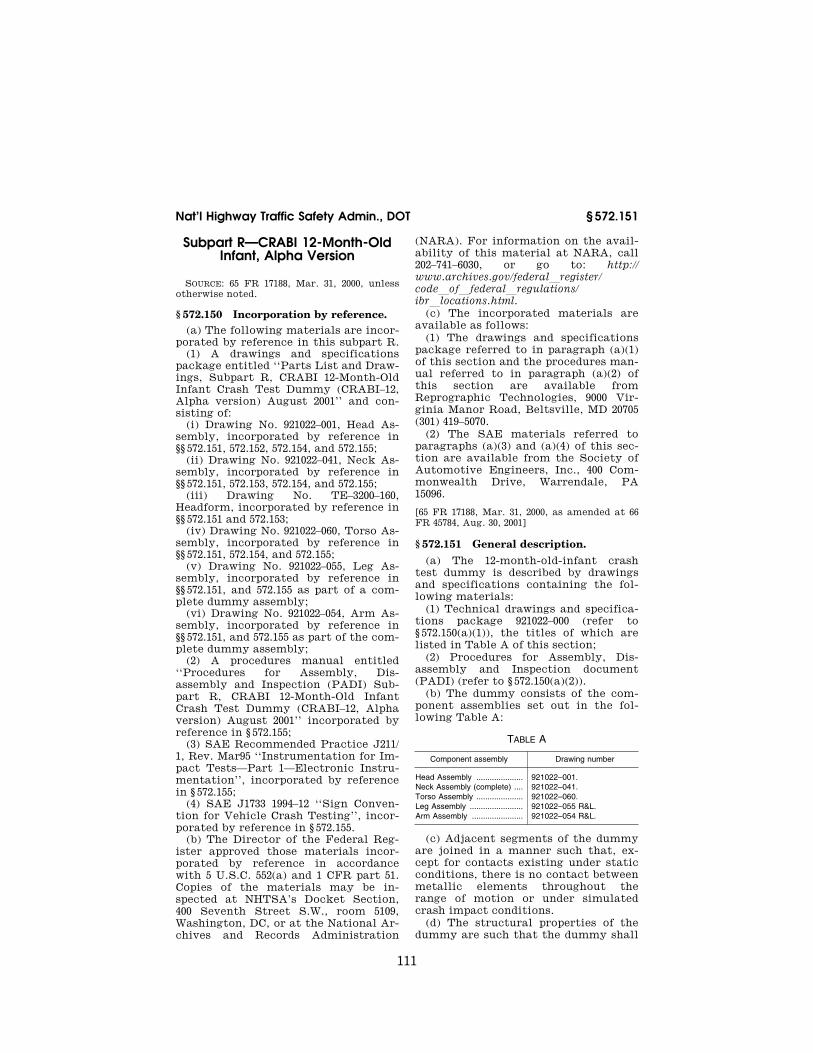
111
Nat’l Highway Traffic Safety Admin., DOT § 572.151
Subpart R—CRABI 12-Month-Old Infant, Alpha Version
SOURCE: 65 FR 17188, Mar. 31, 2000, unless otherwise noted.
§ 572.150 Incorporation by reference. (a) The following materials are incor-
porated by reference in this subpart R. (1) A drawings and specifications
package entitled ‘‘Parts List and Draw-ings, Subpart R, CRABI 12-Month-Old Infant Crash Test Dummy (CRABI–12, Alpha version) August 2001’’ and con-sisting of:
(i) Drawing No. 921022–001, Head As-sembly, incorporated by reference in §§ 572.151, 572.152, 572.154, and 572.155;
(ii) Drawing No. 921022–041, Neck As-sembly, incorporated by reference in §§ 572.151, 572.153, 572.154, and 572.155;
(iii) Drawing No. TE–3200–160, Headform, incorporated by reference in §§ 572.151 and 572.153;
(iv) Drawing No. 921022–060, Torso As-sembly, incorporated by reference in §§ 572.151, 572.154, and 572.155;
(v) Drawing No. 921022–055, Leg As-sembly, incorporated by reference in §§ 572.151, and 572.155 as part of a com-plete dummy assembly;
(vi) Drawing No. 921022–054, Arm As-sembly, incorporated by reference in §§ 572.151, and 572.155 as part of the com-plete dummy assembly;
(2) A procedures manual entitled ‘‘Procedures for Assembly, Dis-assembly and Inspection (PADI) Sub-part R, CRABI 12-Month-Old Infant Crash Test Dummy (CRABI–12, Alpha version) August 2001’’ incorporated by reference in § 572.155;
(3) SAE Recommended Practice J211/ 1, Rev. Mar95 ‘‘Instrumentation for Im-pact Tests—Part 1—Electronic Instru-mentation’’, incorporated by reference in § 572.155;
(4) SAE J1733 1994–12 ‘‘Sign Conven-tion for Vehicle Crash Testing’’, incor-porated by reference in § 572.155.
(b) The Director of the Federal Reg-ister approved those materials incor-porated by reference in accordance with 5 U.S.C. 552(a) and 1 CFR part 51. Copies of the materials may be in-spected at NHTSA’s Docket Section, 400 Seventh Street S.W., room 5109, Washington, DC, or at the National Ar-chives and Records Administration
(NARA). For information on the avail-ability of this material at NARA, call 202–741–6030, or go to: http:// www.archives.gov/federallregister/ codeloflfederallregulations/ ibrllocations.html.
(c) The incorporated materials are available as follows:
(1) The drawings and specifications package referred to in paragraph (a)(1) of this section and the procedures man-ual referred to in paragraph (a)(2) of this section are available from Reprographic Technologies, 9000 Vir-ginia Manor Road, Beltsville, MD 20705 (301) 419–5070.
(2) The SAE materials referred to paragraphs (a)(3) and (a)(4) of this sec-tion are available from the Society of Automotive Engineers, Inc., 400 Com-monwealth Drive, Warrendale, PA 15096.
[65 FR 17188, Mar. 31, 2000, as amended at 66 FR 45784, Aug. 30, 2001]
§ 572.151 General description.
(a) The 12-month-old-infant crash test dummy is described by drawings and specifications containing the fol-lowing materials:
(1) Technical drawings and specifica-tions package 921022–000 (refer to § 572.150(a)(1)), the titles of which are listed in Table A of this section;
(2) Procedures for Assembly, Dis-assembly and Inspection document (PADI) (refer to § 572.150(a)(2)).
(b) The dummy consists of the com-ponent assemblies set out in the fol-lowing Table A:
TABLE A
Component assembly Drawing number
Head Assembly ..................... 921022–001. Neck Assembly (complete) .... 921022–041. Torso Assembly ..................... 921022–060. Leg Assembly ........................ 921022–055 R&L. Arm Assembly ....................... 921022–054 R&L.
(c) Adjacent segments of the dummy are joined in a manner such that, ex-cept for contacts existing under static conditions, there is no contact between metallic elements throughout the range of motion or under simulated crash impact conditions.
(d) The structural properties of the dummy are such that the dummy shall
VerDate Sep<11>2014 10:23 Mar 06, 2017 Jkt 238231 PO 00000 Frm 00121 Fmt 8010 Sfmt 8002 Y:\SGML\238231.XXX 238231jsta
llwor
th o
n D
SK
7TP
TV
N1P
RO
D w
ith C
FR

112
49 CFR Ch. V (10–1–16 Edition) § 572.152
conform to this Subpart in every re-spect before its use in any test under this chapter.
§ 572.152 Head assembly and test pro-cedure.
(a) The head assembly (refer to § 572.150(a)(1)(i)) for this test consists of the assembly (drawing 921022–001), tri-axial mount block (SA572–80), and 3 accelerometers (drawing SA572–S4).
(b) Frontal and rear impact. (1) Fron-tal impact. When the head assembly in paragraph (a) of this section is dropped from a height of 376.0 ±1.0 mm (14.8 ±0.04 in) in accordance with paragraph (c)(3)(i) of this section, the peak result-ant acceleration measured at the head CG shall not be less than 100 g or more than 120 g. The resultant acceleration vs. time history curve shall be unimodal, and the oscillations occur-ring after the main pulse shall be less than 17 percent of the peak resultant acceleration. The lateral acceleration shall not exceed ±15 g’s.
(2) Rear impact. When the head assem-bly in paragraph (a) of this section is dropped from a height of 376.0 ±1.0 mm (14.8 ±0.04 in) in accordance with para-graph (c)(3)(ii) of this section, the peak resultant acceleration measured at the head CG shall be not less than 55 g and not more than 71 g. The resultant ac-celeration vs. time history curve shall be unimodal, and the oscillations oc-curring after the main pulse shall be less than 17 percent of the peak result-ant acceleration. The lateral accelera-tion shall not exceed ±15 g’s.
(c) Head test procedure. The test pro-cedure for the head is as follows:
(1) Soak the head assembly in a con-trolled environment at any tempera-ture between 18.9 and 25.6 °C (66 and 78 °F) and at any relative humidity be-tween 10 and 70 percent for at least four hours prior to a test. These tem-perature and humidity levels shall be maintained throughout the entire test-ing period specified in this section.
(2) Before the test, clean the impact surface of the head skin and the steel impact plate surface with isopropyl al-cohol, trichlorethane, or an equivalent. Both impact surfaces shall be clean and dry for testing.
(3)(i) For a frontal impact test, sus-pend the head assembly with its
midsagittal plane in vertical orienta-tion as shown in Figure R1 of this sub-part. The lowest point on the forehead is 376.0 ±1.0 mm (14.8 ±0.04 in) from the impact surface. The 3.30 mm (0.13 in) diameter holes located on either side of the dummy’s head are used to ensure that the head is level with respect to the impact surface. The angle between the lower surface plane of the neck transducer mass simulator (drawing 910420–003) and the plane of the impact surface is 45 ±1 degrees.
(ii) For a rear impact test, suspend the head assembly with its midsagittal plane in vertical orientation as shown in Figure R2 of this subpart. The low-est point on the back of the head is 376.0 ±1.0 mm (14.8 ±0.04 in) from the im-pact surface. The 3.30 mm (0.13 in) di-ameter holes located on either side of the dummy’s head are used to ensure that the head is level with respect to the impact surface. The angle between the lower surface plane of the neck transducer structural replacement (drawing 910420–003) and the impact surface is 90 ±1 degrees.
(4) Drop the head assembly from the specified height by a means that en-sures a smooth, instant release onto a rigidly supported flat horizontal steel plate which is 50.8 mm (2 in) thick and 610 mm (24 in) square. The impact sur-face shall be clean, dry and have a micro finish of not less than 203.2 × 10¥6 mm (8 micro inches) (RMS) and not more than 2032.0 × 10¥6 mm (80 micro inches) (RMS).
(5) Allow at least 2 hours between successive tests of the head assembly at the same impact point. For head im-pacts on the opposite side of the head, the 30-minute waiting period specified in § 572.155(m) does not apply.
§ 572.153 Neck-headform assembly and test procedure.
(a) The neck and headform assembly (refer to §§ 572.150(a)(1)(ii) and 572.150(a)(1)(iii)) for the purposes of this test consists of parts shown in CRABI neck test assembly (drawing TE–3200– 100);
(b) When the neck and headform as-sembly, as defined in § 572.153(a), is tested according to the test procedure in § 572.153(c), it shall have the fol-lowing characteristics:
VerDate Sep<11>2014 10:23 Mar 06, 2017 Jkt 238231 PO 00000 Frm 00122 Fmt 8010 Sfmt 8002 Y:\SGML\238231.XXX 238231jsta
llwor
th o
n D
SK
7TP
TV
N1P
RO
D w
ith C
FR

113
Nat’l Highway Traffic Safety Admin., DOT § 572.153
(1) Flexion. (i) Plane D referenced in Figure R3 of this subpart shall rotate in the direction of pre-impact flight with respect to the pendulum’s longitu-dinal centerline not less than 75 de-grees and not more than 86 degrees. Within this specified rotation corridor, the peak positive moment about the occipital condyles shall be not less than 36 N-m (26.6 ft-lbf) and not more than 45 N-m (33.2 ft-lbf).
(ii) The positive moment about the occipital condyles shall decay for the first time to 5 N-m (3.7 ft-lbf) between 60 ms and 80 ms after time zero.
(iii) The moment about the occipital condyles shall be calculated by the fol-lowing formula: Moment (N-m) = My ¥
(0.005842m) × (Fx), where My is the mo-ment about the y-axis, Fx is the shear force measured by the neck transducer (drawing SA572 –S23) and 0.005842m is the distance from the point at which the load cell measures the force to the occipital condyle.
(2) Extension. (i) Plane D referenced in Figure R4 of this subpart shall ro-tate in the direction of preimpact flight with respect to the pendulum’s longitudinal centerline not less than 80 degrees and not more than 92 degrees. Within the specified rotation corridor, the peak negative moment about the occipital condyles shall be not more than ¥12 Nm (¥8.9 ft-lbf) and not less than ¥23 N-m (¥17.0 ft-lbf) within the minimum and maximum rotation in-terval.
(ii) The negative moment about the occipital condyles shall decay for the first time to ¥5 Nm (¥3.7 lbf-ft) be-tween 76 ms and 90 ms after time zero.
(iii) The moment about the occipital condyles shall be calculated by the fol-lowing formula: Moment (N-m) = My ¥
(0.005842m) × (Fx), where My is the mo-ment about the y-axis, Fx is the shear force measured by the neck transducer (drawing SA572 –S23) and 0.005842m is
the distance from the point at which the load cell measures the force to the occipital condyle.
(c) Test procedure. (1) Soak the neck assembly in a controlled environment at any temperature between 20.6 and 22.2 °C (69 and 72 °F) and at any relative humidity between 10 and 70 percent for at least four hours prior to a test. These temperature and humidity levels shall be maintained throughout the testing period specified in this section.
(2) Torque the jam nut (drawing 9001336) on the neck cable (drawing ATD–6206) to 0.2 to 0.3 Nm (2–3 in-lbf).
(3) Mount the neck-headform assem-bly, defined in paragraph (b) of this section, on the pendulum so the midsagittal plane of the headform is vertical and coincides with the plane of motion of the pendulum as shown in Figure R3 for flexion and Figure R4 for extension tests.
(i) The moment and rotation data channels are defined to be zero when the longitudinal centerline of the neck and pendulum are parallel.
(ii) The test shall be conducted with-out inducing any torsion of the neck.
(4) Release the pendulum and allow it to fall freely to achieve an impact ve-locity of 5.2 ±0.1 m/s (17.1 ±0.3 ft/s) for flexion and 2.5 ±0.1 m/s (8.2 ±0.3 ft/s) for extension measured at the center of the pendulum accelerometer at the in-stant of contact with the honeycomb.
(i) Time-zero is defined as the time of initial contact between the pendulum striker plate and the honeycomb mate-rial. The pendulum data channel shall be defined to be zero at this time.
(ii) Stop the pendulum from the ini-tial velocity with an acceleration vs. time pulse which meets the velocity change as specified in the following table. Integrate the pendulum accel-eration data channel to obtain the ve-locity vs. time curve as indicated in Table B:
TABLE B—PENDULUM PULSE
Time Flexion Time Extension
m/s m/s ft/s ms m/s ft/s
10 ............................................. 1.6 –2.3 5.2 –7.5 6 .............................................. 0.8 –1.2 2.6 –3.9 20 ............................................. 3.4 –4.2 11.2 –13.8 10 ............................................ 1.5 –2.1 4.9 –6.9 25 ............................................. 4.3 –5.2 14.1 –17.1 14 ............................................ 2.2 –2.9 7.2 –9.5
VerDate Sep<11>2014 10:23 Mar 06, 2017 Jkt 238231 PO 00000 Frm 00123 Fmt 8010 Sfmt 8002 Y:\SGML\238231.XXX 238231jsta
llwor
th o
n D
SK
7TP
TV
N1P
RO
D w
ith C
FR

114
49 CFR Ch. V (10–1–16 Edition) § 572.154
§ 572.154 Thorax assembly and test procedure.
(a) Thorax Assembly (refer to § 572.150(a)(1)(iv)) . The thorax consists of the part of the torso assembly shown in drawing 921022–060.
(b) When the thorax of a completely assembled dummy (drawing 921022–000) is impacted by a test probe conforming to § 572.155(a) at 5.0 ±0.1m/s (16.5 ±0.3 ft/ s) according to the test procedure in paragraph (c) of this section, the peak force, measured by the impact probe in accordance with paragraph § 572.155(a), shall be not less than 1514 N (340.7 lbf) and not more than 1796 N (404.1 lbf).
(c) Test procedure. (1) Soak the dummy in a controlled environment at any temperature between 20.6 and 22.2 °C (69 and 72 °F) and at any relative hu-midity between 10 and 70 percent for at least four hours prior to a test. These temperature and humidity levels shall be maintained throughout the entire testing period specified in this section.
(2) The test dummy is clothed in a cotton-polyester based tight fitting sweat shirt with long sleeves and ankle long pants whose combined weight is not more than 0.25 kg (.55 lbs).
(3) Seat and orient the dummy on a level seating surface without back sup-port as shown in Figure R5 of this sub-part, with the lower limbs extended forward, parallel to the midsagittal plane and the arms 0 to 5 degrees for-ward of vertical. The dummy’s midsagittal plane is vertical within ±/1 degree and the posterior surface of the upper spine box is aligned at 90 ±/1 de-grees from the horizontal. (Shim mate-rial may be used under the upper legs to maintain the dummy’s specified spine box surface alignment).
(4) Establish the impact point at the chest midsagittal plane so that the im-pact point of the longitudinal center-line of the probe coincides with the dummy’s midsagittal plane, is centered on the torso 196 ±/2.5 mm (7.7 ±/0.1 in) vertically from the plane of the seating surface, and is within 0.5 degrees of a horizontal plane.
(5) Impact the thorax with the test probe so that at the moment of contact the probe’s longitudinal center line falls within 2 degrees of a horizontal line in the dummy’s midsagittal plane.
(6) Guide the test probe during im-pact so that there is no significant lat-eral, vertical or rotational movement.
(7) No suspension hardware, suspen-sion cables, or any other attachments to the probe, including the velocity vane, shall make contact with the dummy during the test.
[65 FR 17188, Mar. 31, 2000, as amended at 66 FR 45784, Aug. 30, 2001]
§ 572.155 Test conditions and instru-mentation.
(a) The test probe for thoracic im-pacts, except for attachments, shall be of rigid metallic construction and con-centric about its longitudinal axis. Any attachments to the impactor, such as suspension hardware, impact vanes, etc., must meet the requirements of § 572.154(c)(7). The impactor shall have a mass of 2.86 ±0.02 kg (6.3 ±0.05 lbs) and a minimum mass moment of inertia of 164 kg-cm2 (0.145 lb-in-sec2) in yaw and pitch about the CG of the probe. One- third of the weight of suspension cables and any attachments to the impact probe must be included in the calcula-tion of mass, and such components may not exceed five percent of the total weight of the test probe. The im-pacting end of the probe, perpendicular to and concentric with the longitudinal axis of the probe, has a flat, contin-uous, and non-deformable 101.6 ±0.25 mm (4.00 ±0.01 in) diameter face with an edge radius of 7.6/12.7 mm (0.3/0.5 in). The impactor shall have a 101–103 mm (4–4.1 in) diameter cylindrical surface extending for a minimum of 12.5 mm (0.5 in) to the rear from the impact face. The probe’s end opposite to the impact face has provisions for mount-ing an accelerometer with its sensitive axis collinear with the longitudinal axis of the probe. The impact probe shall have a free air resonant frequency of not less than 1000 Hz measured in line with the longitudinal axis of the impactor, using the test method shown in the Procedures for Assembly, Dis-assembly and Inspection (PADI) docu-ment referenced in § 572.151.
(b) Head accelerometers shall have the dimensions, response characteris-tics, and sensitive mass locations spec-ified in drawing SA572–S4 and be mounted in the head as shown in draw-ing 921022–000.
VerDate Sep<11>2014 10:23 Mar 06, 2017 Jkt 238231 PO 00000 Frm 00124 Fmt 8010 Sfmt 8002 Y:\SGML\238231.XXX 238231jsta
llwor
th o
n D
SK
7TP
TV
N1P
RO
D w
ith C
FR

115
Nat’l Highway Traffic Safety Admin., DOT Pt. 572, Subpt. R, Figs.
(c) The neck force-moment trans-ducer shall have the dimensions, re-sponse characteristics, and sensitive axis locations specified in drawing SA572–S23 and shall be mounted for testing as shown in drawing 921022–000 and in figures R3 and R4 of this sub-part.
(d) The shoulder force transducers shall have the dimensions and response characteristics specified in drawing SA572–S25 and are allowed to be mounted as optional instrumentation in place of part No. 921022–022 in the torso assembly as shown in drawing 921022–000.
(e) The thorax accelerometers shall have the dimensions, response charac-teristics, and sensitive mass locations specified in drawing SA572–S4 and be mounted in the torso assembly in tri-axial configuration as shown in draw-ing 921022–000.
(f) The lumbar spine and lower neck force/moment transducer shall have the dimensions and response character-istics specified in drawing SA572–S23 and are allowed to be mounted as op-tional instrumentation in the torso as-sembly in place of part No. 910420–003 as shown in drawing 921022–000.
(g) The pelvis accelerometers shall have the dimensions, response charac-teristics, and sensitive mass locations specified in drawing SA572–S4 and are allowed to be mounted as optional in-strumentation in the pelvis in triaxial configuration as shown in drawing 921022–000.
(h) The pubic force transducer shall have the dimensions and response char-acteristics specified in drawing SA572– S24 and is allowed to be mounted as op-tional instrumentation in place of part No. 921022–050 in the torso assembly as shown in drawing 921022–000.
(i) The outputs of acceleration and force-sensing devices installed in the dummy and in the test apparatus speci-fied by this part are recorded in indi-vidual data channels that conform to the requirements of SAE Rec-ommended Practice J211/1, Rev. Mar95
‘‘Instrumentation for Impact Tests— Part 1—Electronic Instrumentation’’ (refer to § 572.150(a)(3)), with channel classes as follows:
(1) Head and headform acceleration— Class 1000.
(2) Neck : (i) Forces—Class 1000; (ii) Moments—Class 600; (iii) Pendulum acceleration—Class
180; (iv) Rotation potentiometer response
(if used)—CFC 60. (3) Thorax: (i) Spine and pendulum accelera-
tions—Class 180; (ii) Shoulder forces—Class 600; (4) Lumbar: (i) Forces—Class 1000; (ii) Moments—Class 600; (5) Pelvis: (i) Accelerations—Class 1000; (ii) Pubic—Class 1000. (j) Coordinate signs for instrumenta-
tion polarity shall conform to SAE J1733, 1994–12, ‘‘Sign Convention For Vehicle Crash Testing, Surface Vehicle Information Report,’’ (refer to § 572.150(a)(4)).
(k) The mountings for sensing de-vices shall have no resonance fre-quency within a range of 3 times the frequency range of the applicable chan-nel class.
(l) Limb joints shall be set at l g, barely restraining the weight of the limb when it is extended horizontally. The force required to move a limb seg-ment shall not exceed 2 g throughout the range of limb motion.
(m) Performance tests of the same component, segment, assembly, or fully assembled dummy shall be sepa-rated in time by period of not less than 30 minutes unless otherwise noted.
(n) Surfaces of dummy components may not be painted except as specified in this subpart or in drawings ref-erenced in § 572.150.
[65 FR 17188, Mar. 31, 2000, as amended at 66 FR 45784, Aug. 30, 2001]
FIGURES TO SUBPART R OF PART 572
VerDate Sep<11>2014 10:23 Mar 06, 2017 Jkt 238231 PO 00000 Frm 00125 Fmt 8010 Sfmt 8026 Y:\SGML\238231.XXX 238231jsta
llwor
th o
n D
SK
7TP
TV
N1P
RO
D w
ith C
FR

116
49 CFR Ch. V (10–1–16 Edition) Pt. 572, Subpt. R, Fig. R1
VerDate Sep<11>2014 10:23 Mar 06, 2017 Jkt 238231 PO 00000 Frm 00126 Fmt 8010 Sfmt 8006 Y:\SGML\238231.XXX 238231 ER
31M
R00
.008
</G
PH
>
jsta
llwor
th o
n D
SK
7TP
TV
N1P
RO
D w
ith C
FR

117
Nat’l Highway Traffic Safety Admin., DOT Pt. 572, Subpt. R, Fig. R2
VerDate Sep<11>2014 10:23 Mar 06, 2017 Jkt 238231 PO 00000 Frm 00127 Fmt 8010 Sfmt 8006 Y:\SGML\238231.XXX 238231 ER
31M
R00
.009
</G
PH
>
jsta
llwor
th o
n D
SK
7TP
TV
N1P
RO
D w
ith C
FR

118
49 CFR Ch. V (10–1–16 Edition) Pt. 572, Subpt. R, Fig. R3
VerDate Sep<11>2014 10:23 Mar 06, 2017 Jkt 238231 PO 00000 Frm 00128 Fmt 8010 Sfmt 8006 Y:\SGML\238231.XXX 238231 ER
31M
R00
.010
</G
PH
>
jsta
llwor
th o
n D
SK
7TP
TV
N1P
RO
D w
ith C
FR

119
Nat’l Highway Traffic Safety Admin., DOT Pt. 572, Subpt. R, Fig. R4
VerDate Sep<11>2014 10:23 Mar 06, 2017 Jkt 238231 PO 00000 Frm 00129 Fmt 8010 Sfmt 8006 Y:\SGML\238231.XXX 238231 ER
31M
R00
.011
</G
PH
>
jsta
llwor
th o
n D
SK
7TP
TV
N1P
RO
D w
ith C
FR

120
49 CFR Ch. V (10–1–16 Edition) Pt. 572, Subpt. R, Fig. R5
VerDate Sep<11>2014 10:23 Mar 06, 2017 Jkt 238231 PO 00000 Frm 00130 Fmt 8010 Sfmt 8006 Y:\SGML\238231.XXX 238231 ER
31M
R00
.012
</G
PH
>
jsta
llwor
th o
n D
SK
7TP
TV
N1P
RO
D w
ith C
FR

121
Nat’l Highway Traffic Safety Admin., DOT § 572.161
Subpart S—Hybrid III Six-Year-Old Weighted Child Test Dummy
SOURCE: 69 FR 42602, July 16, 2004, unless otherwise noted.
§ 572.160 Incorporation by reference. (a) The following materials are here-
by incorporated into this subpart S by reference:
(1) A drawings and specifications package entitled, ‘‘Parts List and Drawings, Part 572 Subpart S, Hybrid III 6–Year-Old Child Weighted Crash Test Dummy (H–III6CW),’’ dated June 2009, incorporated by reference in § 572.161 and consisting of:
(i) Drawing No. 167–0000, Complete Assembly, incorporated by reference in § 572.161;
(ii) Drawing No. 167–2000, Upper Torso Assembly, incorporated by reference in §§ 572.161, 572.164, and 572.165 as part of a complete dummy assembly;
(iii) Drawing No. 167–2020, Revision A, Spine Box Weight, incorporated by ref-erence in §§ 572.161, 572.164, and 572.165 as part of a complete dummy assembly;
(iv) Drawing No. 167–3000, Lower Torso Assembly, incorporated by ref-erence in §§ 572.161, and 572.165 as part of a complete dummy assembly;
(v) Drawing No. 167–3010, Revision A, Lumbar Weight Base, incorporated by reference in §§ 572.161 and 572.165 as part of a complete dummy assembly; and
(vi) The Hybrid III Weighted Six- Year-Old Child Parts/Drawing List, in-corporated by reference in § 572.161.
(2) A procedures manual entitled, ‘‘Procedures for Assembly, Dis-assembly, And Inspection (PADI) of the Part 572 Subpart S, Hybrid III 6–Year- Old Child Weighted Crash Test Dummy (H–III6CW), revised June 2009,’’ incor-porated by reference in § 572.161;
(3) The Director of the Federal Reg-ister approved the materials incor-porated by reference in accordance with 5 U.S.C. 552(a) and 1 CFR part 51. Copies of the materials may be in-spected at the Department of Transpor-tation, Docket Operations, Room W12– 140, 1200 New Jersey Avenue, SE., Washington, DC 20590, telephone (202) 366–9826, and at the National Archives and Records Administration (NARA), and in electronic format through Regu-lations.gov. For information on the
availability and inspection of this ma-terial at NARA, call 202–741–6030, or go to: http://www.archives.gov/ federallregister/ codeloflfederallregulations/ ibrllocations.html. For information on the availability and inspection of this material at Regulations.gov, call 1–877– 378–5457, or go to: http:// www.regulations.gov.
(b) The incorporated materials are available as follows:
(1) The Drawings and Specifications for the Hybrid III Six-Year-Old Weight-ed Child Test Dummy referred to in paragraph (a)(1) of this section are available in electronic format through the NHTSA docket center and in paper format from Leet-Melbrook, Division of New RT, 18810 Woodfield Road, Gai-thersburg, MD 20879, (301) 670–0090.
(2) [Reserved]
[69 FR 42602, July 16, 2004, as amended at 70 FR 77338, Dec. 30, 2005; 75 FR 76646, Dec. 9, 2010]
§ 572.161 General description. (a) The Hybrid III Six-Year-Old
Weighted Child Test Dummy is defined by drawings and specifications con-taining the following materials:
(1) ‘‘Parts List and Drawings, Part 572 Subpart S, Hybrid III 6–Year-Old Child Weighted Crash Test Dummy (H– III6CW),’’ dated June 2009 (incorporated by reference, see § 572.160);
(2) The head, neck, arm, and leg as-semblies specified in 49 CFR 572 sub-part N; and
(3) ‘‘Procedures for Assembly, Dis-assembly, And Inspection (PADI) of the Part 572 Subpart S, Hybrid III 6–Year- Old Child Weighted Crash Test Dummy (H–III6CW), revised June 2009’’ (incor-porated by reference, see § 572.160).
TABLE A
Component assembly 1 Drawing No.
Complete assembly .................................... 167–0000. Upper torso assembly ................................. 167–2000. Spine box weight ........................................ 167–2020 Rev.
A. Lower torso assembly ................................. 167–3000. Lumbar weight base ................................... 167–3010 Rev.
A.
1 Head, neck, arm, and leg assemblies are as specified in 49 CFR 572 subpart N.
(b) Adjacent segments are joined in a manner such that except for contacts
VerDate Sep<11>2014 10:23 Mar 06, 2017 Jkt 238231 PO 00000 Frm 00131 Fmt 8010 Sfmt 8002 Y:\SGML\238231.XXX 238231jsta
llwor
th o
n D
SK
7TP
TV
N1P
RO
D w
ith C
FR

122
49 CFR Ch. V (10–1–16 Edition) § 572.162
existing under static conditions, there is no contact between metallic ele-ments throughout the range of motion or under simulated crash impact condi-tions.
(c) The structural properties of the dummy are such that the dummy must conform to Subpart S in every respect and Subpart N as applicable, before use in any test similar to those specified in Standard 208, ‘‘Occupant Crash Protec-tion’’ (49 CFR 571.208), and Standard 213, ‘‘Child Restraint Systems’’ (49 CFR 571.213).
[69 FR 42602, July 16, 2004, as amended at 70 FR 77338, Dec. 30, 2005; 75 FR 76646, Dec. 9, 2010]
§ 572.162 Head assembly and test pro-cedure.
The head assembly is assembled and tested as specified in 49 CFR 572.122 (Subpart N).
§ 572.163 Neck assembly and test pro-cedure.
The neck assembly is assembled and tested as specified in 49 CFR 572.123 (Subpart N).
§ 572.164 Thorax assembly and test procedure.
(a) Thorax (upper torso) assembly. The thorax consists of the part of the torso assembly shown in drawing 167–2000 (in-corporated by reference, see § 572.160).
(b) When the anterior surface of the thorax of a completely assembled dummy (drawing 167–2000) that is seat-ed as shown in Figure S1 is impacted by a test probe conforming to 49 CFR 572.127(a) at 6.71 ±0.12 m/s (22.0 ±0.4 ft/s) according to the test procedure speci-fied in 49 CFR 572.124(c):
(1) The maximum sternum displace-ment relative to the spine, measured with chest deflection transducer (speci-fied in 49 CFR 572.124(b)(1)), must be not less than 38.0 mm (1.50 in) and not more than 46.0 mm (1.80 in). Within this specified compression corridor, the peak force, measured by the probe in accordance with 49 CFR 572.127, must be not less than 1205 N (270.9 lbf) and not more than 1435 N (322.6 lbf). The peak force after 12.5 mm (0.5 in) of ster-num displacement, but before reaching the minimum required 38.0 mm (1.46 in)
sternum displacement limit, must not exceed an upper limit of 1500 N.
(2) The internal hysteresis of the ribcage in each impact as determined by the plot of force vs. deflection in paragraph (b)(1) of this section must be not less than 65 percent but not more than 85 percent.
(c) Test procedure. The thorax assem-bly is tested as specified in 49 CFR 572.124(c).
§ 572.165 Upper and lower torso as-semblies and torso flexion test pro-cedure.
(a) Upper/lower torso assembly. The test objective is to determine the stiff-ness effects of the lumbar spine (speci-fied in 49 CFR 572.125(a)), including cable (specified in 49 CFR 572.125(a)), mounting plate insert (specified in 49 CFR 572.125(a)), nylon shoulder bushing (specified in 49 CFR 572.125(a)), nut (specified in 49 CFR 572.125(a)), spine box weighting plates (drawing 167–2020 Revision A), lumbar base weight (draw-ing 167–3010 Revision A), and abdominal insert (specified in 49 CFR 572.125(a)), on resistance to articulation between the upper torso assembly (drawing 167– 2000) and the lower torso assembly (drawing 167–3000). Drawing Nos. 167– 2000, 167–2020 Revision A, 167–3000, and 167–3010 Revision A, are incorporated by reference, see § 572.160.
(b)(1) When the upper torso assembly of a seated dummy is subjected to a force continuously applied at the head to neck pivot pin level through a rig-idly attached adaptor bracket as shown in Figure S2 according to the test pro-cedure set out in 49 CFR 572.125(c), the lumbar spine-abdomen assembly must flex by an amount that permits the upper torso assembly to translate in angular motion until the machined surface of the instrument cavity at the back of the thoracic spine box is at 45 ±0.5 degrees relative to the transverse plane, at which time the force applied as shown in Figure S2 must be within 88.6 N ±25 N (20.0 lbf ±5.6 lbf), and
(2) Upon removal of the force, the torso assembly must return to within 9 degrees of its initial position.
(c) Test procedure. The upper and lower torso assemblies are tested as specified in 49 CFR 572.125(c), except that in paragraph (c)(5) of that section,
VerDate Sep<11>2014 10:23 Mar 06, 2017 Jkt 238231 PO 00000 Frm 00132 Fmt 8010 Sfmt 8002 Y:\SGML\238231.XXX 238231jsta
llwor
th o
n D
SK
7TP
TV
N1P
RO
D w
ith C
FR

123
Nat’l Highway Traffic Safety Admin., DOT Pt. 572, Subpt. S, Figs.
the initial torso orientation angle may not exceed 32 degrees.
[69 FR 42602, July 16, 2004, as amended at 70 FR 77338, Dec. 30, 2005]
§ 572.166 Knees and knee impact test procedure.
The knee assembly is assembled and tested as specified in 49 CFR 572.126 (Subpart N).
§ 572.167 Test conditions and instru-mentation.
The test conditions and instrumenta-tion are as specified in 49 CFR 572.127 (Subpart N).
FIGURES TO SUBPART S OF PART 572
VerDate Sep<11>2014 10:23 Mar 06, 2017 Jkt 238231 PO 00000 Frm 00133 Fmt 8010 Sfmt 8026 Y:\SGML\238231.XXX 238231jsta
llwor
th o
n D
SK
7TP
TV
N1P
RO
D w
ith C
FR

124
49 CFR Ch. V (10–1–16 Edition) Pt. 572, Subpt. S, Fig. S1
VerDate Sep<11>2014 10:23 Mar 06, 2017 Jkt 238231 PO 00000 Frm 00134 Fmt 8010 Sfmt 8006 Y:\SGML\238231.XXX 238231 ER
16JY
04.0
05<
/GP
H>
jsta
llwor
th o
n D
SK
7TP
TV
N1P
RO
D w
ith C
FR

125
Nat’l Highway Traffic Safety Admin., DOT Pt. 572, Subpt. S, Fig. S2
VerDate Sep<11>2014 10:23 Mar 06, 2017 Jkt 238231 PO 00000 Frm 00135 Fmt 8010 Sfmt 8006 Y:\SGML\238231.XXX 238231 ER
16JY
04.0
06<
/GP
H>
jsta
llwor
th o
n D
SK
7TP
TV
N1P
RO
D w
ith C
FR

126
49 CFR Ch. V (10–1–16 Edition) § 572.170
Subpart T—Hybrid III 10-Year-Old Child Test Dummy (HIII–10C)
SOURCE: 77 FR 11667, Feb. 27, 2012, unless otherwise noted.
§ 572.170 Incorporation by reference. (a) Certain material is incorporated
by reference (IBR) into this part with the approval of the Director of the Fed-eral Register under 5 U.S.C. 552(a) and 1 CFR part 51. To enforce any edition other than that specified in this sec-tion, NHTSA must publish notice of change in the FEDERAL REGISTER and the material must be available to the public. All approved material is avail-able for inspection at the Department of Transportation, Docket Operations, Room W12–140, telephone 202–366–9826, and is available from the sources listed below. The material is available in electronic format through Regula-tions.gov, call 1–877–378–5457 or go to www.regulations.gov. It is also available for inspection at the National Archives and Records Administration (NARA). For information on the availability of this material at NARA, call 202–741– 6030 or go to http://www.archives.gov/fed-eral-register/cfr/ibr-locations.html.
(b) NHTSA Technical Information Services, 1200 New Jersey Ave., SE., Washington, DC 20590, telephone 202– 366–5965.
(1) A parts/drawing list entitled, ‘‘Parts/Drawing List, Part 572 Subpart T, Hybrid III 10 Year Old Child Test Dummy (HIII–10C), March, 2015,’’ IBR approved for § 572.171.
(2) A drawings and inspection pack-age entitled, ‘‘Parts List and Drawings, Part 572 Subpart T, Hybrid III 10 Year Old Child Crash Dummy (HIII–10C), March 2015,’’ IBR approved for § 572.171, including:
(i) Drawing No. 420–0000, Complete Assembly HIII 10-year-old, IBR ap-proved for §§ 572.171, 572.172, 572.173, 572.174, 572.176, and 572.177.
(ii) Drawing No. 420–1000, Head As-sembly, IBR approved for § 572.171, § 572.172, § 572.173, and § 572.177.
(iii) Drawing No. 420–2000, Neck As-sembly, IBR approved for §§ 572.171, 572.173, and 572.177.
(iv) Drawing No. 420–3000, Upper Torso Assembly, IBR approved for §§ 572.171, 572.174, 572.175, and 572.177.
(v) Drawing No. 420–4000, Lower Torso Assembly, IBR approved for §§ 572.171, 572.174, 572.175, and 572.177.
(vi) Drawing No. 420–5000–1, Complete Leg Assembly—left, IBR approved for §§ 572.171, 572.176, and 572.177.
(vii) Drawing No. 420–5000–2, Com-plete Leg Assembly—right, IBR ap-proved for §§ 572.171, 572.176, and 572.177.
(viii) Drawing No. 420–7000–1, Com-plete Arm Assembly—left, IBR ap-proved for § 572.171, and,
(ix) Drawing No. 420–7000–2, Complete Arm Assembly—right, IBR approved for § 572.171.
(3) A procedures manual entitled ‘‘Procedures for Assembly, Dis-assembly, and Inspection (PADI) of the Hybrid III 10 Year Old Child Test Dummy (HIII–10C), March 2015’’; IBR approved for §§ 572.171 and 572.177.
(c) SAE International, 400 Common-wealth Drive, Warrendale, PA 15096, call 1–877–606–7323.
(1) SAE Recommended Practice J211/ 1, Rev. Mar 95, ‘‘Instrumentation for Impact Tests—Part 1—Electronic In-strumentation,’’ IBR approved for § 572.177.
(2) SAE Information Report J1733 of 1994–12, ‘‘Sign Convention for Vehicle Crash Testing,’’ December 1994, IBR ap-proved for § 572.177.
[77 FR 11667, Feb. 27, 2012, as amended at 80 FR 35860, June 23, 2015]
§ 572.171 General description. (a) The Hybrid III 10-year-old Child
Test Dummy (HIII–10C) is defined by drawings and specifications containing the following materials:
(1) The parts enlisted in ‘‘Parts/Draw-ing List, Part 572 Subpart T, Hybrid III 10 Year Old Child Test Dummy (HIII– 10C), March, 2015’’ (incorporated by ref-erence, see § 572.170),
(2) The engineering drawings and specifications contained in ‘‘Parts List and Drawings, Part 572 Subpart T, Hy-brid III 10 Year Old Child Crash Dummy (HIII–10C), March 2015,’’ which includes the engineering drawings and specifications described in Drawing 420–0000, the titles of the assemblies of which are listed in Table A, and,
(3) A manual entitled ‘‘Procedures for Assembly, Disassembly, and Inspection (PADI) of the Hybrid III 10 Year Old
VerDate Sep<11>2014 10:23 Mar 06, 2017 Jkt 238231 PO 00000 Frm 00136 Fmt 8010 Sfmt 8002 Y:\SGML\238231.XXX 238231jsta
llwor
th o
n D
SK
7TP
TV
N1P
RO
D w
ith C
FR

127
Nat’l Highway Traffic Safety Admin., DOT § 572.173
Child Test Dummy (HIII–10C), March 2015.’’
TABLE A
Component assembly Drawing No.
(i) Head Assembly ............................................................................................................................................. 420–1000 (ii) Neck Assembly ............................................................................................................................................ 420–2000 (iii) Upper Torso Assembly ................................................................................................................................ 420–3000 (iv) Lower Torso Assembly ............................................................................................................................... 420–4000 (v) Complete Leg Assembly—left ..................................................................................................................... 420–5000–1 (vi) Complete Leg Assembly—right .................................................................................................................. 420–5000–2 (vii) Complete Arm Assembly—left ................................................................................................................... 420–7000–1 (viii) Complete Arm Assembly—right ................................................................................................................ 420–7000–2
(b) The structural properties of the dummy are such that the dummy con-forms to this Subpart in every respect before use in any test.
[77 FR 11667, Feb. 27, 2012, as amended at 80 FR 35860, June 23, 2015]
§ 572.172 Head assembly and test pro-cedure.
(a) The head assembly for this test consists of the complete head (drawing 420–1000), a six-axis neck transducer (drawing SA572–S11, included in draw-ing 420–0000), or its structural replace-ment (drawing 420–383X), and 3 accelerometers (drawing SA572–S4, in-cluded in drawing 420–0000) (all incor-porated by reference, see § 572.170).
(b) When the head assembly is dropped from a height of 376.0 ±1.0 mm (14.8 ±0.04 in) in accordance with para-graph (c) of this section, the peak re-sultant acceleration at the location of the accelerometers at the head CG may not be less than 250 G or more than 300 G. The resultant acceleration vs. time history curve shall be unimodal; oscil-lations occurring after the main pulse must be less than 10 percent of the peak resultant acceleration. The lat-eral acceleration shall not exceed 15 G (zero to peak).
(c) Head test procedure. The test pro-cedure for the head is as follows:
(1) Soak the head assembly in a con-trolled environment at any tempera-ture between 18.9 and 25.6 °C (66 and 78 °F) and a relative humidity from 10 to 70 percent for at least four hours prior to a test.
(2) Prior to the test, clean the impact surface of the skin and the impact plate surface with isopropyl alcohol, trichloroethane, or an equivalent. The
skin of the head must be clean and dry for testing.
(3) Suspend and orient the head as-sembly as shown in Figure T1. The low-est point on the forehead must be 376.0 ±1.0 mm (14.8 ±0.04 in) from the impact surface. The 1.57 mm (0.062 in) diameter holes located on either side of the dum-my’s head shall be used to ensure that the head is level with respect to the impact surface.
(4) Drop the head assembly from the specified height by means that ensure a smooth, instant release onto a rigidly supported flat horizontal steel plate which is 50.8 mm (2 in) thick and 610 mm (24 in) square. The impact surface shall be clean, dry and have a micro finish of not less than 203.2 × 10¥6 mm (8 micro inches) (RMS) and not more than 2032.0 × 10¥6 mm (80 micro inches) (RMS).
(5) Allow at least 2 hours between successive tests on the same head.
§ 572.173 Neck assembly and test pro-cedure.
(a) The neck assembly for the pur-poses of this test consists of the assem-bly of components shown in drawing 420–2000 (incorporated by reference, see § 572.170).
(b) When the head-neck assembly consisting of the head (drawing 420– 1000), neck (drawing 420–2000), six-chan-nel neck transducer (SA572–S11, in-cluded in drawing 420–0000), lower neck bracket assembly (drawing 420–2070), and either three uniaxial accelerometers (drawing SA572–S4, in-cluded in drawing 420–0000) or their mass equivalent installed in the head assembly as specified in drawing 420– 1000 (all incorporated by reference, see § 572.170), is tested according to the test
VerDate Sep<11>2014 10:23 Mar 06, 2017 Jkt 238231 PO 00000 Frm 00137 Fmt 8010 Sfmt 8002 Y:\SGML\238231.XXX 238231jsta
llwor
th o
n D
SK
7TP
TV
N1P
RO
D w
ith C
FR

128
49 CFR Ch. V (10–1–16 Edition) § 572.173
procedure in paragraph (c) of this sec-tion, it shall have the following charac-teristics:
(1) Flexion. (i) Plane D, referenced in Figure T2, shall rotate in the direction of preimpact flight with respect to the pendulum’s longitudinal centerline be-tween 76 degrees and 90 degrees. During the time interval while the rotation is within the specified corridor, the peak moment, measured by the neck trans-ducer (drawing SA572–S11, included in drawing 420–0000) (incorporated by ref-erence, see § 572.170), about the occipi-tal condyles may not be less than 50 N- m (36.9 ft-lbf) and not more than 62 N- m (45.7 ft-lbf). The positive moment shall decay for the first time to 10 N-m (7.4 ft-lbf) between 86 ms and 105 ms after time zero.
(ii) The moment shall be calculated by the following formula: Moment (N- m) = My ¥ (0.01778) × (FX).
(iii) My is the moment about the y- axis in Newton-meters, FX is the shear force measured by the neck transducer (drawing SA572–S11) in Newtons, and 0.01778 is the distance in meters from the load center of the neck transducer to the occipital condyle.
(2) Extension. (i) Plane D, referenced in Figure T3, shall rotate in the direc-tion of preimpact flight with respect to the pendulum’s longitudinal centerline between 96 degrees and 115 degrees. During the time interval while the ro-tation is within the specified corridor, the peak moment, measured by the neck transducer (drawing SA572–S11, included in drawing 420–0000) (incor-porated by reference, see § 572.170), about the occipital condyles may not be more than ¥37 N-m (¥27.3 ft-lbf) and not less than ¥46 N-m (¥33.9 ft- lbf). The positive moment shall decay for the first time to ¥10 N-m (¥7.4 ft- lbf) between 100 ms and 116 ms after time zero.
(ii) The moment shall be calculated by the following formula: Moment (N- m) = My ¥ (0.01778) × (FX).
(iii) My is the moment about the y- axis in Newton-meters, FX is the shear
force measured by the neck transducer (drawing SA572–S11, included in draw-ing 420–0000) (incorporated by ref-erence, see § 572.170) in Newtons, and 0.01778 is the distance in meters from the load center of the neck transducer to the occipital condyle.
(3) Time zero is defined as the time of initial contact between the pendulum striker plate and the honeycomb mate-rial. All data channels shall be at the zero level at this time.
(c) Test procedure. The test procedure for the neck assembly is as follows:
(1) Soak the neck assembly in a con-trolled environment at any tempera-ture between 20.6 and 22.2 °C (69 and 72 °F) and a relative humidity between 10 and 70 percent for at least four hours prior to a test.
(2) Torque the hex nut (drawing 420– 2000, part 9000130) on the neck cable (drawing 420–2060) (both incorporated by reference, see § 572.170) to 0.9 ±0.2 N- m (8 ±2 in-lbf) before each test on the same neck.
(3) Mount the head-neck assembly, defined in paragraph (b) of this section, on the pendulum described in Figure 22 of 49 CFR part 572 so that the leading edge of the lower neck bracket coin-cides with the leading edge of the pen-dulum as shown in Figure T2 for flex-ion tests and Figure T3 for extension tests.
(4)(i) Release the pendulum and allow it to fall freely from a height to achieve an impact velocity of 6.1 ±0.12 m/s (20.0 ±0.4 ft/s) for flexion tests and 5.03 ±0.12 m/s (16.50 ±0.40 ft/s) for exten-sion tests, measured by an acceler-ometer mounted on the pendulum as shown in Figure T2 at the instant of contact with the honeycomb.
(ii) Stop the pendulum from the ini-tial velocity with an acceleration vs. time pulse that meets the velocity change as specified below. Integrate the pendulum acceleration data chan-nel to obtain the velocity vs. time curve:
TABLE B—PENDULUM PULSE
Time (ms)
Flexion Extension
M/s ft/s m/s ft/s
10 .......................................................................................... 1.64–2.04 5.38–6.69 1.49–1.89 4.89–6.20
VerDate Sep<11>2014 10:23 Mar 06, 2017 Jkt 238231 PO 00000 Frm 00138 Fmt 8010 Sfmt 8002 Y:\SGML\238231.XXX 238231jsta
llwor
th o
n D
SK
7TP
TV
N1P
RO
D w
ith C
FR
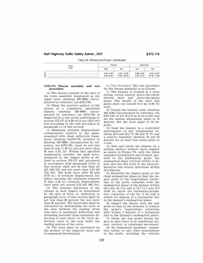
129
Nat’l Highway Traffic Safety Admin., DOT § 572.174
TABLE B—PENDULUM PULSE—Continued
Time (ms)
Flexion Extension
M/s ft/s m/s ft/s
20 .......................................................................................... 3.04–4.04 9.97–13.25 2.88–3.68 9.45–12.07 30 .......................................................................................... 4.45–5.65 14.60–18.53 4.20–5.20 13.78–17.06
§ 572.174 Thorax assembly and test procedure.
(a) The thorax consists of the part of the torso assembly designated as the upper torso (drawing 420–3000) (incor-porated by reference, see § 572.170).
(b) When the anterior surface of the thorax of a completely assembled dummy (drawing 420–0000) (incor-porated by reference, see § 572.170) is impacted by a test probe conforming to section 572.177 at 6.00 ±0.12 m/s (22.0 ±0.4 ft/s) according to the test procedure in paragraph (c) of this section:
(1) Maximum sternum displacement (compression) relative to the spine, measured with chest deflection trans-ducer (drawing SA572–T4, included in drawing 420–0000) (incorporated by ref-erence, see § 572.170), must be not less than 37 mm (1.46 in) and not more than 46 mm (1.81 in). Within this specified compression corridor, the peak force, measured by the impact probe as de-fined in section 572.177 and calculated in accordance with paragraph (b)(3) of this section, shall not be less than 2.0 kN (450 lbf) and not more than 2.45 kN (551 lbf). The peak force after 20 mm (0.79 in.) of sternum displacement but before reaching the minimum required 37 mm (1.46 in.) sternum displacement limit shall not exceed 2.52 kN (567 lbf).
(2) The internal hysteresis of the ribcage in each impact as determined by the plot of force vs. deflection in paragraph (a)(1) of this section shall be not less than 69 percent but not more than 85 percent. The hysteresis shall be calculated by determining the ratio of the area between the loading (from time zero to maximum deflection) and unloading portions (from maximum de-flection to zero force) of the force de-flection curve to the area under the loading portion of the curve.
(3) The force shall be calculated by the product of the impactor mass and its measured deceleration.
(c) Test Procedure. The test procedure for the thorax assembly is as follows:
(1) The dummy is clothed in a form fitting cotton stretch above-the-elbow sleeved shirt and above-the-knees pants. The weight of the shirt and pants shall not exceed 0.14 kg (0.30 lb) each.
(2) Torque the lumbar cable (drawing 420–4130) (incorporated by reference, see § 572.170) to 0.9 ±0.2 N-m (8 ±2 in-lbf) and set the lumbar adjustment angle to 12 degrees. Set the neck angle to 16 de-grees.
(3) Soak the dummy in a controlled environment at any temperature be-tween 20.6 and 22.2 °C (69 and 72 °F) and a relative humidity between 10 and 70 percent for at least four hours prior to a test.
(4) Seat and orient the dummy on a seating surface without back support as shown in Figure T4, with the limbs extended horizontally and forward, par-allel to the midsagittal plane, the midsagittal plane vertical within ±1 de-gree and the ribs level in the anterior- posterior and lateral directions within ±0.5 degrees.
(5) Establish the impact point at the chest midsagittal plane so that the im-pact point of the longitudinal center-line of the probe coincides with the midsagittal plane of the dummy within ±2.5 mm (0.1 in) and is 12.7 ±1.1 mm (0.5 ±0.04 in) below the horizontal-periph-eral centerline of the No. 3 rib and is within 0.5 degrees of a horizontal line in the dummy’s midsagittal plane.
(6) Impact the thorax with the test probe so that at the moment of contact the probe’s longitudinal centerline falls within 2 degrees of a horizontal line in the dummy’s midsagittal plane.
(7) Guide the test probe during im-pact so that there is no significant lat-eral, vertical, or rotational movement.
(8) No suspension hardware, suspen-sion cables, or any other attachments to the probe, including the velocity
VerDate Sep<11>2014 10:23 Mar 06, 2017 Jkt 238231 PO 00000 Frm 00139 Fmt 8010 Sfmt 8002 Y:\SGML\238231.XXX 238231jsta
llwor
th o
n D
SK
7TP
TV
N1P
RO
D w
ith C
FR

130
49 CFR Ch. V (10–1–16 Edition) § 572.175
vane, shall make contact with the dummy during the test.
§ 572.175 Upper and lower torso as-semblies and torso flexion test pro-cedure.
(a) The test objective is to determine the stiffness of the molded lumbar as-sembly (drawing 420–4100), abdominal insert (drawing 420–4300), and chest flesh assembly (drawing 420–3560) on re-sistance to articulation between the upper torso assembly (drawing 420–3000) and lower torso assembly (drawing 420– 4000) (all incorporated by reference, see § 572.170).
(b) When the upper torso assembly of a seated dummy is subjected to a force continuously applied at the head to neck pivot pin level through a rigidly attached adaptor bracket as shown in Figure T5 according to the test proce-dure set out in paragraph (c) of this section:
(1) The lumbar spine-abdomen-chest flesh assembly shall flex by an amount that permits the upper torso assembly to translate in angular motion relative to the vertical transverse plane 35 ±0.5 degrees at which time the force applied must be not less than 180 N (40.5 lbf) and not more than 250 N (56.2 lbf).
(2) Upon removal of the force, the torso assembly must return to within 8 degrees of its initial position.
(c) Test Procedure. The test procedure for the upper/lower torso assembly is as follows:
(1) Torque the lumbar cable (drawing 420–4130) (incorporated by reference, see § 572.170) to 0.9 ±0.2 N-m (8 ±2 in-lbf) and set the lumbar adjustment angle to 12 degrees. Set the neck angle to 16 de-grees.
(2) Soak the dummy in a controlled environment at any temperature be-tween 20.6 and 22.2 °C (69 and 72 °F) and a relative humidity between 10 and 70 percent for at least four hours prior to a test.
(3) Assemble the complete dummy (with or without the legs below the fe-murs) and attach to the fixture in a seated posture as shown in Figure T5.
(4) Secure the pelvis to the fixture at the pelvis instrument cavity rear face by threading four 1⁄4-inch cap screws into the available threaded attachment holes. Tighten the mountings so that
the test material is rigidly affixed to the test fixture and the pelvic-lumbar joining surface is 18 degrees from hori-zontal and the legs are parallel with the test fixture.
(5) Attach the loading adaptor brack-et to the spine of the dummy as shown in Figure T5.
(6) Inspect and adjust, if necessary, the seating of the abdominal insert within the pelvis cavity and with re-spect to the chest flesh, assuring that the chest flesh provides uniform fit and overlap with respect to the outside sur-face of the pelvis flesh.
(7) Flex the dummy’s upper torso three times between the vertical and until the torso reference frame, as shown in Figure T5, reaches 30 degrees from the vertical transverse plane. Bring the torso to vertical orientation and wait for 30 minutes before con-ducting the test. During the 30-minute waiting period, the dummy’s upper torso shall be externally supported at or near its vertical orientation to pre-vent it from drooping.
(8) Remove all external support and wait two minutes. Measure the initial orientation angle of the torso reference plane of the seated, unsupported dummy as shown in Figure T5. The ini-tial orientation angle may not exceed 20 degrees.
(9) Attach the pull cable and the load cell as shown in Figure T5.
(10) Apply a tension force in the midsagittal plane to the pull cable as shown in Figure T5 at any upper torso deflection rate between 0.5 and 1.5 de-grees per second, until the angle ref-erence plane is at 35 ±0.5 degrees of flexion relative to the vertical trans-verse plane.
(11) Continue to apply a force suffi-cient to maintain 35 ±0.5 degrees of flexion for 10 seconds, and record the highest applied force during the 10-sec-ond period.
(12) Release all force at the attach-ment bracket as rapidly as possible, and measure the return angle with re-spect to the initial angle reference plane as defined in paragraph (c)(7) of this section three minutes after the re-lease.
VerDate Sep<11>2014 10:23 Mar 06, 2017 Jkt 238231 PO 00000 Frm 00140 Fmt 8010 Sfmt 8002 Y:\SGML\238231.XXX 238231jsta
llwor
th o
n D
SK
7TP
TV
N1P
RO
D w
ith C
FR

131
Nat’l Highway Traffic Safety Admin., DOT § 572.177
§ 572.176 Knees and knee impact test procedure.
(a) The knee assembly for the pur-pose of this test is the part of the leg assembly shown in drawing 420–5000 (in-corporated by reference, see § 572.170).
(b) When the knee assembly, con-sisting of lower upper leg assembly (420–5200), femur load transducer (SA572–S10, included in drawing 420– 0000) or its structural replacement (420– 5121), lower leg assembly (420–5300), ankle assembly (420–5400), and foot molded assembly (420–5500) (all incor-porated by reference, see § 572.170) is tested according to the test procedure in subsection (c) of this section:
(1) The peak resistance force as meas-ured with the test probe-mounted ac-celerometer must not be less than 2.6 kN (585 lbf) and not more than 3.2 kN (719 lbf).
(2) The force shall be calculated by the product of the impactor mass and its deceleration.
(c) Test Procedure. The test procedure for the knee assembly is as follows:
(1) Soak the knee assembly in a con-trolled environment at any tempera-ture between 20.6 and 22.2 °C (69 and 72 °F) and a relative humidity between 10 and 70 percent for at least four hours prior to a test.
(2) Mount the test material and se-cure it to a rigid test fixture as shown in Figure T6. No part of the foot or tibia may contact any exterior surface.
(3) Align the test probe so that throughout its stroke and at contact with the knee it is within 2 degrees of horizontal and collinear with the longi-tudinal centerline of the femur.
(4) Guide the pendulum so that there is no significant lateral, vertical, or ro-tational movement at the time of ini-tial contact between the impactor and the knee.
(5) The test probe velocity at the time of contact shall be 2.1 ±0.03 m/s (6.9 ±0.1 ft/s).
(6) No suspension hardware, suspen-sion cables, or any other attachments to the probe, including the velocity vane, shall make contact with the dummy during the test.
§ 572.177 Test conditions and instru-mentation.
(a) The following test equipment and instrumentation is needed for quali-fication as set forth in this subpart:
(1) The test probe for thoracic im-pacts is of rigid metallic construction, concentric in shape, and symmetric about its longitudinal axis. It has a mass of 6.89 ±0.05 kg (15.2 ±0.1 lb) and a minimum mass moment of inertia of 2040 kg-cm2 (1.81 lbf-in-sec2) in yaw and pitch about the CG. One-third (1⁄3) of the weight of the suspension cables and their attachments to the impact probe is included in the calculation of mass, and such components may not exceed five percent of the total weight of the test probe. The impacting end of the probe, perpendicular to and concentric with the longitudinal axis, is at least 25.4 mm (1.0 in) long, and has a flat, continuous, and non-deformable 121 ±0.25 mm (4.76 ±0.01 in) diameter face with a maximum edge radius of 12.7 mm (0.5 in). The probe’s end opposite to the impact face has provisions for mounting of an accelerometer with its sensitive axis collinear with the longi-tudinal axis of the probe. No concentric portions of the impact probe may ex-ceed the diameter of the impact face. The impact probe has a free air reso-nant frequency of not less than 1000 Hz, which may be determined using the procedure listed in the PADI (incor-porated by reference, see § 572.170).
(2) The test probe for knee impacts is of rigid metallic construction, concen-tric in shape, and symmetric about its longitudinal axis. It has a mass of 1.91 ±0.05 kg (4.21 ±0.1 lb) and a minimum mass moment of inertia of 140 kg-cm2 (0.124 lbf-in-sec2) in yaw and pitch about the CG. One third (1⁄3) of the weight of the suspension cables and their attachments to the impact probe may be included in the calculation of mass, and such components may not exceed five percent of the total weight of the test probe. The impacting end of the probe, perpendicular to and concen-tric with the longitudinal axis, is at least 12.5 mm (0.5 in) long, and has a flat, continuous, and non-deformable 76.2 ±0.2 mm (3.00 ±0.01 in) diameter face with a maximum edge radius of 12.7 mm (0.5 in). The probe’s end opposite to the impact face has provisions for
VerDate Sep<11>2014 10:23 Mar 06, 2017 Jkt 238231 PO 00000 Frm 00141 Fmt 8010 Sfmt 8002 Y:\SGML\238231.XXX 238231jsta
llwor
th o
n D
SK
7TP
TV
N1P
RO
D w
ith C
FR

132
49 CFR Ch. V (10–1–16 Edition) § 572.177
mounting an accelerometer with its sensitive axis collinear with the longi-tudinal axis of the probe. No concentric portions of the impact probe may ex-ceed the diameter of the impact face. The impact probe has a free air reso-nant frequency of not less than 1000 Hz, which may be determined using the procedure listed in the PADI (incor-porated by reference, see § 572.170).
(3) Head accelerometers have dimen-sions, response characteristics, and sensitive mass locations specified in drawing SA572–S4 (included in drawing 420–0000) and are mounted in the head as shown in drawing 420–0000 (both in-corporated by reference, see § 572.170), sheet 2 of 6.
(4) The upper neck force and moment transducer has the dimensions, re-sponse characteristics, and sensitive axis locations specified in drawing SA572–S11 (included in drawing 420– 0000) and is mounted in the head-neck assembly as shown in drawing 420–0000 (both incorporated by reference, see § 572.170), sheet 2 of 6.
(5) The chest deflection transducer has the dimensions and response char-acteristics specified in drawing SA572– S50 (included in drawing 420–0000) and is mounted to the upper torso assembly as shown in drawing 420–0000 (both in-corporated by reference, see § 572.170), sheet 2 of 6.
(b) The following instrumentation may be required for installation in the dummy for compliance testing. If so, it is installed during qualification proce-dures as described in this subpart:
(1) The thorax CG accelerometers have the dimensions, response charac-teristics, and sensitive mass locations specified in drawing SA572–S4 (included in drawing 420–0000) (incorporated by reference, see § 572.170) and are mount-ed in the torso assembly in a triaxial configuration within the spine box in-strumentation cavity.
(2) The lower neck force and moment transducer has the dimensions, re-sponse characteristics, and sensitive axis locations specified in drawing SA572–S40 (included in drawing 420– 0000) and is mounted to the neck as-sembly by replacing the lower neck mounting bracket 420–2070 as shown in drawing 420–2000 (all incorporated by reference, see § 572.170).
(3) The clavicle force transducers have the dimensions, response charac-teristics, and sensitive axis locations specified in drawing SA572–S41 (in-cluded in drawing 420–0000) and are mounted in the shoulder assembly as shown in drawing 420–3800 (both incor-porated by reference, see § 572.170).
(4) The IR–Tracc chest deflection transducers have the dimensions and response characteristics specified in drawing SA572–S43 (included in draw-ing 420–0000) and are mounted to the spine box assembly as shown in draw-ing 420–8000 (both incorporated by ref-erence, see § 572.170).
(5) The spine and sternum accelerometers have the dimensions, response characteristics, and sensitive mass locations specified in drawing SA572–S4 (included in drawing 420–0000) and are mounted in the torso assembly in uniaxial fore-and-aft oriented con-figuration arranged as corresponding pairs in two locations each on the ster-num and at the spine box of the upper torso assembly as shown in drawing 420–0000 (both incorporated by ref-erence, see § 572.170), sheet 2 of 6.
(6) The lumbar spine force-moment transducer has the dimensions, re-sponse characteristics, and sensitive axis locations specified in drawing SA572–S12 (included in drawing 420– 0000) and is mounted in the lower torso assembly as shown in drawing 420–4000 (both incorporated by reference, see § 572.170).
(7) The iliac force transducers have the dimensions and response character-istics specified in drawing SA572–S13 L and R (included in drawing 420–0000) and are mounted in the lower torso as-sembly as shown in drawing 420–4000 (both incorporated by reference, see § 572.170).
(8) The pelvis accelerometers have the dimensions, response characteris-tics, and sensitive mass locations spec-ified in drawing SA572–S4 (included in drawing 420–0000) and are mounted in the torso assembly in triaxial configu-ration in the pelvis bone as shown in drawing 420–0000 (both incorporated by reference, see § 572.170), sheet 2 of 6.
(9) The femur force and moment transducers (SA572–S10, included in drawing 420–0000) have the dimensions, response characteristics, and sensitive
VerDate Sep<11>2014 10:23 Mar 06, 2017 Jkt 238231 PO 00000 Frm 00142 Fmt 8010 Sfmt 8002 Y:\SGML\238231.XXX 238231jsta
llwor
th o
n D
SK
7TP
TV
N1P
RO
D w
ith C
FR

133
Nat’l Highway Traffic Safety Admin., DOT § 572.177
axis locations specified in the appro-priate drawing and are mounted in the upper leg assembly, replacing the femur load cell simulator (drawing 420– 5121) as shown in drawing 420–5100 (all incorporated by reference, see § 572.170).
(10) The tilt sensors have the dimen-sions and response characteristics spec-ified in drawing SA572–S42 (included in drawing 420–0000) and are mounted to the head, thorax, and pelvis assemblies as shown in drawing 420–0000 (both in-corporated by reference, see § 572.170), sheet 2 of 6.
(c) The outputs of transducers in-stalled in the dummy and in the test equipment specified by this part are to be recorded in individual data channels that conform to SAE Recommended Practice J211 (incorporated by ref-erence, see § 572.170) except as noted, with channel frequency classes as fol-lows:
(1) Pendulum acceleration, CFC 180, (2) Pendulum D-plane rotation (if
transducer is used), CFC 60, (3) Torso flexion pulling force (if
transducer is used), CFC 60, (4) Head acceleration, CFC 1000, (5) Neck forces, upper and lower, CFC
1000, (6) Neck moments, upper and lower,
CFC 600, (7) Thorax CG acceleration, CFC 180, (8) Sternum deflection, Class 600, (9) Sternum and rib accelerations,
Class 1000, (10) Spine accelerations, CFC 180, (11) Lumbar forces, CFC 1000,
(12) Lumbar moments, CFC 600, (13) Shoulder forces, CFC 180, (14) Pelvis accelerations, CFC 1000, (15) Iliac forces, CFC 180, (16) Femur and tibia forces, CFC 600, (17) Femur and tibia moments, CFC
600. (18) Thorax probe acceleration, CFC
180, (19) Knee probe acceleration, CFC 600. (d) Coordinate signs for instrumenta-
tion polarity are to conform to SAE In-formation Report J1733 (incorporated by reference, see § 572.170).
(e) The mountings for sensing devices have no resonant frequency less than 3 times the frequency range of the appli-cable channel class.
(f) Limb joints are set at one G, bare-ly restraining the weight of the limb when it is extended horizontally. The force needed to move a limb segment is not to exceed 2G throughout the range of limb motion.
(g) Performance tests of the same component, segment, assembly, or fully assembled dummy are separated in time by not less than 30 minutes un-less otherwise noted.
(h) Surfaces of dummy components may not be painted except as specified in this subpart or in drawings sub-tended by this subpart.
[77 FR 11667, Feb. 27, 2012, as amended at 80 FR 35860, June 23, 2015]
APPENDIX—FIGURES TO SUBPART T OF PART 572
VerDate Sep<11>2014 10:23 Mar 06, 2017 Jkt 238231 PO 00000 Frm 00143 Fmt 8010 Sfmt 8002 Y:\SGML\238231.XXX 238231jsta
llwor
th o
n D
SK
7TP
TV
N1P
RO
D w
ith C
FR

134
49 CFR Ch. V (10–1–16 Edition) § 572.177
VerDate Sep<11>2014 10:23 Mar 06, 2017 Jkt 238231 PO 00000 Frm 00144 Fmt 8010 Sfmt 8006 Y:\SGML\238231.XXX 238231 ER
27F
E12
.003
</G
PH
>
jsta
llwor
th o
n D
SK
7TP
TV
N1P
RO
D w
ith C
FR

135
Nat’l Highway Traffic Safety Admin., DOT § 572.177
VerDate Sep<11>2014 10:23 Mar 06, 2017 Jkt 238231 PO 00000 Frm 00145 Fmt 8010 Sfmt 8006 Y:\SGML\238231.XXX 238231 ER
27F
E12
.004
</G
PH
>
jsta
llwor
th o
n D
SK
7TP
TV
N1P
RO
D w
ith C
FR

136
49 CFR Ch. V (10–1–16 Edition) § 572.177
VerDate Sep<11>2014 10:23 Mar 06, 2017 Jkt 238231 PO 00000 Frm 00146 Fmt 8010 Sfmt 8006 Y:\SGML\238231.XXX 238231 ER
27F
E12
.005
</G
PH
>
jsta
llwor
th o
n D
SK
7TP
TV
N1P
RO
D w
ith C
FR

137
Nat’l Highway Traffic Safety Admin., DOT § 572.177
VerDate Sep<11>2014 10:23 Mar 06, 2017 Jkt 238231 PO 00000 Frm 00147 Fmt 8010 Sfmt 8006 Y:\SGML\238231.XXX 238231 ER
27F
E12
.006
</G
PH
>E
R27
FE
12.0
07<
/GP
H>
jsta
llwor
th o
n D
SK
7TP
TV
N1P
RO
D w
ith C
FR

138
49 CFR Ch. V (10–1–16 Edition) § 572.180
Subpart U—ES–2re Side Impact Crash Test Dummy, 50th Per-centile Adult Male
SOURCE: 71 FR 75331, Dec. 14, 2006, unless otherwise noted.
§ 572.180 Incorporated materials. (a) The following materials are here-
by incorporated into this Subpart by reference:
(1) A parts/drawing list entitled, ‘‘Parts/Drawings List, Part 572 Subpart U, Eurosid 2 with Rib Extensions (ES2re), September 2009,’’ incorporated by reference in § 572.181.
(2) A drawings and inspection pack-age entitled ‘‘Parts List and Drawings, Part 572 Subpart U, Eurosid 2 with Rib Extensions (ES–2re, Alpha Version), September 2009,’’ consisting of:
(i) Drawing No. 175–0000, ES–2re Dummy Assembly, incorporated by ref-erence, see §§ 572.181, 575.182, 572.184;
(ii) Drawing No. 175–1000, Head As-sembly, incorporated by reference in §§ 572.181 and 572.182;
(iii) Drawing No. 175–2000, Neck As-sembly Test/Cert, incorporated by ref-erence in §§ 572.181 and 572.183;
(iv) Drawing No. 175–3000, Shoulder Assembly, incorporated by reference in §§ 572.181 and 572.184;
(v) Drawing No. 175–3500, Arm Assem-bly, Left, incorporated by reference in §§ 572.181 and 572.185;
(vi) Drawing No. 175–3800, Arm As-sembly, Right, incorporated by ref-erence in §§ 572.181, and 572.185;
(vii) Drawing No. 175–4000, Thorax As-sembly with Rib Extensions, incor-porated by reference in §§ 572.181 and 572.185;
(viii) Drawing No. 175–5000, Abdom-inal Assembly, incorporated by ref-erence in §§ 572.181 and 572.186;
(ix) Drawing No. 175–5500, Lumbar Spine Assembly, incorporated by ref-erence in §§ 572.181 and 572.187;
(x) Drawing No. 175–6000, Pelvis As-sembly, incorporated by reference in §§ 572.181 and 572.188;
(xi) Drawing No. 175–7000–1, Leg As-sembly—left incorporated by reference in § 572.181;
(xii) Drawing No. 175–7000–2, Leg As-sembly—right incorporated by ref-erence in § 572.181;
VerDate Sep<11>2014 10:23 Mar 06, 2017 Jkt 238231 PO 00000 Frm 00148 Fmt 8010 Sfmt 8002 Y:\SGML\238231.XXX 238231 ER
27F
E12
.008
</G
PH
>
jsta
llwor
th o
n D
SK
7TP
TV
N1P
RO
D w
ith C
FR

139
Nat’l Highway Traffic Safety Admin., DOT § 572.181
(xiii) Drawing No. 175–8000, Neoprene Body Suit, incorporated by reference in §§ 572.181 and 572.185; and,
(xiv) Drawing No. 175–9000, Headform Assembly, incorporated by reference in §§ 572.181, 572.183, 572.187;
(3) A procedures manual entitled ‘‘Procedures for Assembly, Dis-assembly and Inspection (PADI) of the EuroSID–2re 50th Percentile Adult Male Side Impact Crash Test Dummy, February 2008,’’ incorporated by ref-erence in §§ 572.180(a)(2), and 572.181(a);
(4) Society of Automotive Engineers (SAE) Recommended Practice J211, Rev. Mar 95 ‘‘Instrumentation for Im-pact Tests—Part 1—Electronic Instru-mentation’’; and,
(5) SAE J1733 of 1994–12 ‘‘Sign Con-vention for Vehicle Crash Testing.’’
(b) The Director of the Federal Reg-ister approved the materials incor-porated by reference in accordance with 5 U.S.C. 552(a) and 1 CFR part 51. Copies of the materials may be in-spected at the Department of Transpor-tation, Docket Operations, Room W12– 140, 1200 New Jersey Avenue, SE., Washington, DC 20590, telephone (202) 366–9826, and at the National Archives and Records Administration (NARA), and in electronic format through Regu-lations.gov. For information on the availability and inspection of this ma-terial at NARA, call 202–741–6030, or go to: http://www.archives.gov/ federallregister/ codeloflfederallregulations/ ibrllocations.html. For information on the availability and inspection of this material at Regulations.gov, call 1–877– 378–5457, or go to: http:// www.regulations.gov.
(c) The incorporated materials are available as follows:
(1) The Parts/Drawings List, Part 572 Subpart U, Eurosid 2 with Rib Exten-sions (ES2re) referred to in paragraph (a)(1) of this section, the Parts List and Drawings, Part 572 Subpart U, Eurosid 2 with Rib Extensions (ES–2re, Alpha Version) referred to in paragraph (a)(2) of this section, and the PADI document referred to in paragraph (a)(3) of this section, are available in electronic for-mat through Regulations.gov and in paper format from Leet-Melbrook, Di-vision of New RT, 18810 Woodfield
Road, Gaithersburg, MD 20879, tele-phone (301) 670–0090.
(2) The SAE materials referred to in paragraphs (a)(4) and (a)(5) of this sec-tion are available from the Society of Automotive Engineers, Inc., 400 Com-monwealth Drive, Warrendale, PA 15096, telephone 1–877–606–7323.
[71 FR 75331, Dec. 14, 2006, as amended at 73 FR 33920, June 16, 2008; 76 FR 31864, June 2, 2011]
§ 572.181 General description.
(a) The ES–2re Side Impact Crash Test Dummy, 50th Percentile Adult Male, is defined by:
(1) The drawings and specifications contained in the ‘‘Parts List and Draw-ings, Part 572 Subpart U, Eurosid 2 with Rib Extensions (ES–2re, Alpha Version), September 2009,’’ (incor-porated by reference, see § 572.180), which includes the technical drawings and specifications described in Drawing 175–0000, the titles of which are listed in Table A;
TABLE A
Component assembly Drawing No.
Head Assembly ........................................... 175–1000 Neck Assembly Test/Cert ........................... 175–2000 Neck Bracket Including Lifting Eyebolt ....... 175–2500 Shoulder Assembly ..................................... 175–3000 Arm Assembly-Left ...................................... 175–3500 Arm Assembly-Right ................................... 175–3800 Thorax Assembly with Rib Extensions ....... 175–4000 Abdominal Assembly ................................... 175–5000 Lumbar Spine Assembly ............................. 175–5500 Pelvis Assembly .......................................... 175–6000 Leg Assembly, Left ..................................... 175–7000–1 Leg Assembly, Right ................................... 175–7000–2 Neoprene Body Suit .................................... 175–8000
(2) ‘‘Parts/Drawings List, Part 572 Subpart U, Eurosid 2 with Rib Exten-sions (ES2re), September 2009,’’ con-taining 9 pages, incorporated by ref-erence, see § 572.180,
(3) A listing of available transducers- crash test sensors for the ES–2re Crash Test Dummy is shown in drawing 175– 0000 sheet 4 of 6, dated February 2008, incorporated by reference, see § 572.180,
(4) Procedures for Assembly, Dis-assembly and Inspection (PADI) of the ES–2re Side Impact Crash Test Dummy, February 2008, incorporated by reference, see § 572.180,
VerDate Sep<11>2014 10:23 Mar 06, 2017 Jkt 238231 PO 00000 Frm 00149 Fmt 8010 Sfmt 8002 Y:\SGML\238231.XXX 238231jsta
llwor
th o
n D
SK
7TP
TV
N1P
RO
D w
ith C
FR

140
49 CFR Ch. V (10–1–16 Edition) § 572.182
(5) Sign convention for signal outputs reference document SAE J1733 Infor-mation Report, titled ‘‘Sign Conven-tion for Vehicle Crash Testing’’ dated December 1994, incorporated by ref-erence, see § 572.180.
(b) Exterior dimensions of ES–2re test dummy are shown in drawing 175– 0000 sheet 3 of 6, dated February 2008, incorporated by reference, see § 572.180.
(c) Weights of body segments (head, neck, upper and lower torso, arms and upper and lower segments) and the cen-ter of gravity location of the head are shown in drawing 175–0000 sheet 2 of 6, dated February 2008, incorporated by reference, see § 572.180.
(d) Adjacent segments are joined in a manner such that, except for contacts existing under static conditions, there is no additional contact between me-tallic elements of adjacent body seg-ments throughout the range of motion.
(e) The structural properties of the dummy are such that the dummy con-forms to this Subpart in every respect before use in any test similar to those in Standard No. 214, Side Impact Pro-tection and Standard No. 201, Occupant Protection in Interior Impact.
[71 FR 75331, Dec. 14, 2006, as amended at 73 FR 33921, June 16, 2008; 76 FR 31866, June 2, 2011]
§ 572.182 Head assembly. (a) The head assembly consists of the
head (drawing 175–1000), including the neck upper transducer structural re-placement, and a set of three (3) accelerometers in conformance with specifications in § 572.189(b) and mount-ed as shown in drawing (175–0000 sheet 1 of 6). When tested to the test proce-dure specified in paragraph (b) of this section, the head assembly shall meet performance requirements specified in paragraph (c) of this section.
(b) Test procedure. The head shall be tested per procedure specified in 49 CFR § 572.112(a).
(c) Performance criteria. (1) When the head assembly is dropped in accordance with § 572.112 (a), the measured peak re-sultant acceleration shall be between 125 g’s and 155 g’s;
(2) The resultant acceleration-time curve shall be unimodal to the extent that oscillations occurring after the main acceleration pulse shall not ex-
ceed 15% (zero to peak) of the main pulse;
(3) The fore-and-aft component of the head acceleration shall not exceed 15 g’s.
§ 572.183 Neck assembly. (a) The neck assembly consists of
parts shown in drawing 175–2000. For purposes of this test, the neck is mounted within the headform assembly 175–9000 as shown in Figure U1 in ap-pendix A to this subpart. When sub-jected to tests procedures specified in paragraph (b) of this section, the neck- headform assembly shall meet perform-ance requirements specified in para-graph (c) of this section.
(b) Test procedure. (1) Soak the neck- headform assembly in a test environ-ment as specified in § 572.189(n);
(2) Attach the neck-headform assem-bly to the part 572 subpart E pendulum test fixture as shown in Figure U2–A in appendix A to this subpart, so that the midsagittal plane of the neck-headform assembly is vertical and perpendicular to the plane of motion of the pendulum longitudinal centerline shown in Fig-ure U2–A. Torque the half-spherical screws (175–2004) located at either end of the neck assembly to 88 ±5 in-lbs using the neck compression tool (175– 9500) or equivalent;
(3) Release the pendulum from a height sufficient to allow it to fall free-ly to achieve an impact velocity of 3.4±0.1 m/s measured at the center of the pendulum accelerometer (Figure 22 as set forth in 49 CFR 572.33) at the time the pendulum makes contact with the decelerating mechanism. The ve-locity-time history of the pendulum falls inside the corridor determined by the upper and lower boundaries speci-fied in Table 1 to paragraph (a) of this section.
(4) Allow the neck to flex without the neck-headform assembly making con-tact with any object;
(5) Time zero is defined in § 572.189(j).
TABLE 1 TO PARAGRAPH (a)—ES–2RE NECK CERTIFICATION PENDULUM VELOCITY CORRIDOR
Upper boundary Lower boundary
Time (ms)
Velocity (m/s)
Time (ms)
Velocity (m/s)
1.0 .................................. 0.00 0.0 ¥0.05
VerDate Sep<11>2014 10:23 Mar 06, 2017 Jkt 238231 PO 00000 Frm 00150 Fmt 8010 Sfmt 8002 Y:\SGML\238231.XXX 238231jsta
llwor
th o
n D
SK
7TP
TV
N1P
RO
D w
ith C
FR

141
Nat’l Highway Traffic Safety Admin., DOT § 572.185
TABLE 1 TO PARAGRAPH (a)—ES–2RE NECK CERTIFICATION PENDULUM VELOCITY COR-RIDOR—Continued
Upper boundary Lower boundary
Time (ms)
Velocity (m/s)
Time (ms)
Velocity (m/s)
3.0 .................................. ¥0.25 2.5 ¥0.375 14.0 ................................ ¥3.20 13.5 ¥3.7
17.0 ¥3.7
(c) Performance criteria. (1) The pen-dulum deceleration pulse is to be char-acterized in terms of decrease in veloc-ity as determined by integrating the filtered pendulum acceleration re-sponse from time-zero.
(2) The maximum rotation in the lat-eral direction of the reference plane of the headform (175–9000) as shown in Figure U2–B in appendix A to this sub-part, shall be 49 to 59 degrees with re-spect to the longitudinal axis of the pendulum occurring between 54 and 66 ms from time zero. Rotation of the headform-neck assembly and the neck angle with respect to the pendulum shall be measured with potentiometers specified in § 572.189(c), installed as shown in drawing 175–9000, and cal-culated per procedure specified in Fig-ure U2–B in appendix A to this subpart;
(3) The decaying headform rotation vs. time curve shall cross the zero angle with respect to its initial posi-tion at time of impact relative to the pendulum centerline between 53 ms to 88 ms after the time the peak trans-lation-rotation value is reached.
[71 FR 75331, Dec. 14, 2006, as amended at 73 FR 33921, June 16, 2008]
§ 572.184 Shoulder assembly. (a) The shoulder (175–3000) is part of
the body assembly shown in drawing 175–0000. When subjected to impact tests specified in paragraph (b) of this section, the shoulder assembly shall meet performance requirements of paragraph (c) of this section.
(b) Test procedure. (1) Soak the dummy assembly, without suit and shoulder foam pad (175–3010), in a test environment as specified in § 572.189(n);
(2) The dummy is seated, as shown in Figure U3 in appendix A to this sub-part, on a flat, horizontal, rigid surface covered by two overlaid 2 mm thick Teflon sheets and with no back support
of the dummy’s torso. The dummy’s torso spine backplate is vertical within ±2 degrees and the midsagittal plane of the thorax is positioned perpendicular to the direction of the plane of motion of the impactor at contact with the shoulder. The arms are oriented for-ward at 50±2 degrees from the hori-zontal, pointing downward. The dum-my’s legs are horizontal and symmet-rical about the midsaggital plane with the distance between the innermost point on the opposite ankle at 100 ±5 mm. The length of the elastic shoulder cord (175–3015) shall be adjusted so that a force between and including 27.5 and 32.5 N applied in a forward direction at 4 ±1 mm from the outer edge of the clavicle in the same plane as the clav-icle movement, is required to initiate a forward motion of 1 to 5 mm;
(3) The impactor is the same as de-fined in § 572.189(a);
(4) The impactor is guided, if needed, so that at contact with the shoulder, its longitudinal axis is within ±0.5 de-grees of a horizontal plane and perpen-dicular (±0.5 degrees) to the midsagittal plane of the dummy and the centerpoint on the impactor’s face is within 5 mm of the center of the upper arm pivot bolt (5000040) at contact with the test dummy, as shown in Figure U3 in appendix A to this subpart;
(5) The impactor impacts the dum-my’s shoulder at 4.3±0.1 m/s.
(c) Performance criteria. The peak ac-celeration of the impactor is between 7.5 g’s and 10.5 g’s during the pen-dulum’s contact with the dummy.
§ 572.185 Thorax (upper torso) assem-bly.
(a) The thorax assembly of the dummy must meet the requirements of both (b) and (c) of this section. Section 572.185(b) specifies requirements for an individual rib drop test, and § 572.185(c) specifies requirements for a full-body thorax impact test.
(b) Individual rib drop test. For pur-poses of this test, the rib modules (175– 4002), which are part of the thorax as-sembly (175–4000), are tested as indi-vidual units. When subjected to test procedures specified in paragraph (b)(1) of this section, the rib modules shall meet performance requirements speci-fied in paragraph (b)(2) of this section.
VerDate Sep<11>2014 10:23 Mar 06, 2017 Jkt 238231 PO 00000 Frm 00151 Fmt 8010 Sfmt 8002 Y:\SGML\238231.XXX 238231jsta
llwor
th o
n D
SK
7TP
TV
N1P
RO
D w
ith C
FR

142
49 CFR Ch. V (10–1–16 Edition) § 572.185
Each rib is tested at both the 459 mm and 815 mm drop height tests described in paragraphs (b)(1)(v)(A) and (B) of this section.
(1) Test procedure. (i) Soak the rib modules (175–4002) in a test environ-ment as specified in 572.189(n);
(ii) Mount the rib module rigidly in a drop test fixture as shown in Figure U7 in appendix A to this subpart with the impacted side of the rib facing up;
(iii) The drop test fixture contains a free fall guided mass of 7.78±0.01 kg that is of rigid construction and with a flat impact face 150±1.0 mm in diameter and an edge radius of ±0.25 mm;
(iv) Align the vertical longitudinal centerline of the drop mass so that the centerpoint of the downward-facing flat surface is aligned to impact the centerline of the rib rail guide system within ±2.5 mm.
(v) The impacting mass is dropped from the following heights:
(A) 459 ±5 mm (B) 815 ±8 mm (vi) A test cycle consists of one drop
from each drop height specified in paragraph (b)(1)(v) of this section. Allow a period of not less than five (5) minutes between impacts in a single test cycle. Allow a period of not less than thirty (30) minutes between two separate cycles of the same rib module.
(2) Performance criteria. (i) Each of the rib modules shall de-
flect as specified in paragraphs (b)(2)(i)(A) and (B) of this section, with the deflection measurements made with the internal rib module position transducer specified in § 572.189(d):
(A) Not less than 36 mm and not more than 40 mm when impacted by the mass dropped from 459 mm; and,
(B) Not less than 46 mm and not more than 51mm when impacted by the mass dropped from 815 mm.
(c) Full-body thorax impact test. The thorax is part of the upper torso assem-bly shown in drawing 175–4000. For this full-body thorax impact test, the dummy is tested as a complete assem-bly (drawing 175–0000) with the struck- side arm (175–3500, left arm; 175–3800, right arm) removed. The dummy’s tho-rax is equipped with deflection poten-tiometers as specified in drawing SA572–S69. When subjected to the test procedures specified in paragraph (c)(1)
of this section, the thorax shall meet the performance requirements set forth in paragraph (c)(2).
(1) Test Procedure. (i) Soak the dummy assembly (175–0000), with struck-side arm (175–3500, left arm; 175– 3800, right arm), shoulder foam pad (175–3010), and neoprene body suit (175– 8000) removed, in a test environment as specified in § 572.189(n);
(ii) The dummy is seated, as shown in Figure U4 in appendix A to this sub-part, on a flat, horizontal, rigid surface covered by two overlaid 2 mm thick Teflon sheets and with no back support of the dummy’s torso. The dummy’s torso spine backplate is vertical within ±2 degrees and the midsagittal plane of thorax is positioned perpendicular to the direction of the plane of motion of the impactor at contact with the tho-rax. The non-struck side arm is ori-ented vertically, pointing downward. The dummy’s legs are horizontal and symmetrical about the midsagittal plane with the distance between the in-nermost point on the opposite ankle at 100 ±5 mm;
(iii) The impactor is the same as de-fined in § 572.189(a);
(iv) The impactor is guided, if need-ed, so that at contact with the thorax its longitudinal axis is within ±0.5 de-grees of horizontal and perpendicular ±0.5 degrees to the midsagittal plane of the dummy and the centerpoint of the impactor’s face is within 5 mm of the impact point on the dummy’s middle rib shown in Figure U4 in appendix A to this subpart;
(v) The impactor impacts the dum-my’s thorax at 5.5 m/s ±0.1 m/s.
(vi) Time zero is defined in § 572.189(k).
(2) Performance Criteria. (i) The indi-vidual rib modules shall conform to the following range of deflections:
(A) Upper rib not less than 34 mm and not greater than 41 mm;
(B) Middle rib not less than 37 mm and not greater than 45 mm;
(C) Lower rib not less than 37 mm and not greater than 44 mm.
(ii) The impactor force shall be com-puted as the product of the impact probe acceleration and its mass. The peak impactor force at any time after 6 ms from time zero shall be not less
VerDate Sep<11>2014 10:23 Mar 06, 2017 Jkt 238231 PO 00000 Frm 00152 Fmt 8010 Sfmt 8002 Y:\SGML\238231.XXX 238231jsta
llwor
th o
n D
SK
7TP
TV
N1P
RO
D w
ith C
FR

143
Nat’l Highway Traffic Safety Admin., DOT § 572.187
than 5100 N and not greater than 6200 N.
[71 FR 75331, Dec. 14, 2006, as amended at 73 FR 33921, June 16, 2008]
§ 572.186 Abdomen assembly.
(a) The abdomen assembly (175–5000) is part of the dummy assembly shown in drawing 175–0000 including load sen-sors specified in § 572.189(e). When sub-jected to tests procedures specified in paragraph (b) of this section, the abdo-men assembly shall meet performance requirements specified in paragraph (c) of this section.
(b) Test procedure. (1) Soak the dummy assembly (175–
0000), without suit (175–8000) and shoul-der foam pad (175–3010), as specified in § 572.189(n);
(2) The dummy is seated as shown in Figure U5 in appendix A to this sub-part;
(3) The abdomen impactor is the same as specified in § 572.189(a) except that on its rectangular impact surface is affixed a special purpose block whose weight is 1.0 ±0.01 kg. The block is 70 mm high, 150 mm wide and 60 to 80 mm deep. The impact surface is flat, has a minimum Rockwell hardness of M85, and an edge radius of 4 to 5 mm. The block’s wide surface is horizontally ori-ented and centered on the longitudinal axis of the probe’s impact face as shown in Figure U5–A in appendix A to this subpart;
(4) The impactor is guided, if needed, so that at contact with the abdomen its longitudinal axis is within ±0.5 de-grees of a horizontal plane and perpen-dicular ±0.5 degrees to the midsagittal plane of the dummy and the centerpoint on the impactor’s face is aligned within 5 mm of the center point of the middle load measuring sensor in the abdomen as shown in Fig-ure U5;
(5) The impactor impacts the dum-my’s abdomen at 4.0 m/s ±0.1 m/s;
(6) Time zero is defined in § 572.189(k). (c) Performance criteria. (1) The maximum sum of the forces of
the three abdominal load sensors, spec-ified in 572.189(e), shall be not less than 2200 N and not more than 2700 N and shall occur between 10 ms and 12.3 ms from time zero. The calculated sum of
the three load cell forces must be con-current in time.
(2) Maximum impactor force (impact probe acceleration multiplied by its mass) is not less than 4000 N and not more than 4800 N occurring between 10.6 ms and 13.0 ms from time zero.
§ 572.187 Lumbar spine. (a) The lumbar spine assembly con-
sists of parts shown in drawing 175– 5500. For purposes of this test, the lum-bar spine is mounted within the headform assembly 175–9000 as shown in Figure U1 in appendix A to this sub-part. When subjected to tests proce-dures specified in paragraph (b) of this section, the lumbar spine-headform as-sembly shall meet performance re-quirements specified in paragraph (c) of this section.
(b) Test procedure. (1) Soak the lum-bar spine-headform assembly in a test environment as specified in § 572.189(n);
(2) Attach the lumbar spine-headform assembly to the Part 572 pendulum test fixture per procedure in § 572.183(b)(2) and as shown in Figure U2–A in appen-dix A to this subpart. Torque the lum-bar hex nut (p/n 9000057) on to the lum-bar cable assembly (175–5506) to 50 ±5 in-lb;
(3) Release the pendulum from a height sufficient to allow it to fall free-ly to achieve an impact velocity of 6.05 ±0.1 m/s measured at the center of the pendulum accelerometer (Figure 22) at the time the pendulum makes contact with its decelerating mechanism. The velocity-time history of the pendulum falls inside the corridor determined by the upper and lower boundaries speci-fied in Table 1 to paragraph (b) of this section;
(4) Allow the lumbar spine to flex without the lumbar spine or the headform making contact with any ob-ject;
(5) Time zero is defined in § 572.189(j).
TABLE 1 TO PARAGRAPH (b)—ES–2RE LUMBAR SPINE CERTIFICATION PENDULUM VELOCITY CORRIDOR
Upper boundary Lower boundary
Time (ms)
Velocity (m/s)
Time (ms)
Velocity (m/s)
1.0 0.00 0.0 ¥0 .05 3.7 ¥0.24 2.7 ¥0 .425
27.0 ¥5.80 24.5 ¥6 .50
VerDate Sep<11>2014 10:23 Mar 06, 2017 Jkt 238231 PO 00000 Frm 00153 Fmt 8010 Sfmt 8002 Y:\SGML\238231.XXX 238231jsta
llwor
th o
n D
SK
7TP
TV
N1P
RO
D w
ith C
FR

144
49 CFR Ch. V (10–1–16 Edition) § 572.188
TABLE 1 TO PARAGRAPH (b)—ES–2RE LUMBAR SPINE CERTIFICATION PENDULUM VELOCITY CORRIDOR—Continued
Upper boundary Lower boundary
Time (ms)
Velocity (m/s)
Time (ms)
Velocity (m/s)
30.0 ¥6 .50
(c) Performance criteria. (1) The pen-dulum deceleration pulse is to be char-acterized in terms of decrease in veloc-ity as determined by integrating the filtered pendulum acceleration re-sponse from time-zero.
(2) The maximum rotation in the lat-eral direction of the reference plane of the headform (175–9000) as shown in Figure U2–B in appendix A to this sub-part, shall be 45 to 55 degrees with re-spect to the longitudinal axis of the pendulum occurring between 39 and 53 ms from time zero. Rotation of the headform-neck assembly shall be meas-ured with potentiometers specified in § 572.189(c), installed as shown in draw-ing 175–9000, and calculated per proce-dure specified in Figure U2–B in appen-dix A to this subpart.
(3) The decaying headform rotation vs. time curve shall cross the zero angle with respect to its initial posi-tion at impact relative to the pen-dulum centerline between 37 ms to 57 ms after the time the peak translation- rotation value is reached.
[71 FR 75331, Dec. 14, 2006, as amended at 73 FR 33921, June 16, 2008]
§ 572.188 Pelvis. (a) The pelvis (175–6000) is part of the
torso assembly shown in drawing 175– 0000. The pelvis is equipped with a pubic symphysis load sensor in con-formance with § 572.189(f) and mounted as shown in drawing (175–0000 sheet 4). When subjected to tests procedures specified in paragraph (b) of this sec-tion, the pelvis assembly shall meet performance requirements specified in paragraph (c) of this section.
(b) Test procedure. (1) Soak the dummy assembly (175–
0000) without suit (175–8000) and shoul-der foam pad (175–3010) as specified in § 572.189(n);
(2) The dummy is seated as specified in Figure U6 in appendix A to this sub-part;
(3) The pelvis impactor is the same as specified in § 572.189(a);
(4) The impactor is guided, if needed, so that at contact with the pelvis its longitudinal axis is within ±0.5 degrees of a horizontal plane and perpendicular to the midsagittal plane of the dummy and the centerpoint on the impactor’s face is within 5 mm of the center of the H-point in the pelvis, as shown in Fig-ure U6 in appendix A to this subpart;
(5) The impactor impacts the dum-my’s pelvis at 4.3 ±0.1 m/s.
(6) Time zero is defined in § 572.189(k). (c) Performance criteria. (1) The impac-
tor force (probe acceleration multiplied by its mass) shall be not less than 4,700 N and not more than 5,400 N, occurring between 11.8 ms and 16.1 ms from time zero;
(2) The pubic symphysis load, meas-ured with load cell specified in § 572.189(f) shall be not less than 1,230 N and not more than 1,590 N occurring be-tween 12.2 ms and 17.0 ms from time zero.
[71 FR 75331, Dec. 14, 2006, as amended at 73 FR 33921, June 16, 2008]
§ 572.189 Instrumentation and test conditions.
(a) The test probe for lateral shoul-der, thorax without arm, abdomen, and pelvis impact tests is the same as that specified in § 572.36(a) and the impact probe has a minimum mass moment of inertia in yaw of 9,000 kg-cm2, a free air resonant frequency not less than 1,000 Hz and the probe’s end opposite to the impact face has provisions to mount an accelerometer with its sensitive axis collinear with the longitudinal axis of the probe. All hardware attached di-rectly to the impactor and one-third (1⁄3) of the mass of the suspension ca-bles must be included in the calcula-tions of the total impactor mass. The sum mass of the attachments and 1⁄3 cable mass must not exceed 5 percent of the total pendulum mass. No suspen-sion hardware, suspension cables, or any other attachments to the test probe, including velocity vane, shall make contact with the dummy during the test.
(b) Accelerometers for the head, the thoracic spine, and the pelvis conform to specifications of SA572–S4.
VerDate Sep<11>2014 10:23 Mar 06, 2017 Jkt 238231 PO 00000 Frm 00154 Fmt 8010 Sfmt 8002 Y:\SGML\238231.XXX 238231jsta
llwor
th o
n D
SK
7TP
TV
N1P
RO
D w
ith C
FR

145
Nat’l Highway Traffic Safety Admin., DOT § 572.189
(c) Rotary potentiometer for the neck and lumbar spine certification tests conforms to SA572–53.
(d) Linear position transducer for the thoracic rib conforms to SA572–S69.
(e) Load sensors for the abdomen con-form to specifications of SA572–S75.
(f) Load sensor for the pubic sym-physis conforms to specifications of SA572–77.
(g) Load sensor for the lumbar spine conforms to specifications of SA572–76.
(h) Instrumentation and sensors con-form to the Recommended Practice SAE J–211 (Mar. 1995)—Instrumenta-tion for Impact Test unless noted oth-erwise.
(i) All instrumented response signal measurements shall be treated to the following specifications:
(1) Head acceleration—Digitally fil-tered CFC 1000;
(2) Neck and lumbar spine rotations— Digitally filtered CFC 180;
(3)Neck and lumbar spine pendulum accelerations—Digitally filtered CFC 60;
(4) Pelvis, shoulder, thorax without arm, and abdomen impactor accelera-tions—Digitally filtered CFC 180;
(5) Abdominal and pubic symphysis force—Digitally filtered at CFC 600;
(6) Thorax deflection—Digitally fil-tered CFC 180.
(j)(1) Filter the pendulum accelera-tion data using a SAE J211 CFC 60 fil-ter.
(2) Determine the time when the fil-tered pendulum accelerometer data first crosses the ¥10 g level (T10).
(3) Calculate time-zero: T0 = T10¥Tm, Where:
Tm = 1.417 ms for the Neck Test = 1.588 ms for the Lumbar Spine Test
(4) Set the data time-zero to the sam-ple number nearest to the calculated T0.
(k)(1) Filter the pendulum accelera-tion data using a SAE J211 CFC 180 fil-ter.
(2) Determine the time when the fil-tered pendulum accelerometer data first crosses the ¥1.0 m/s2 (¥.102 g) ac-celeration level (T0).
(3) Set the data time-zero to the sam-ple number of the new T0.
(l) Mountings for the head, spine and pelvis accelerometers shall have no resonance frequency within a range of 3 times the frequency range of the appli-cable channel class.
(m) Limb joints of the test dummy are set at the force between 1 to 2 G’s, which just supports the limb’s weight when the limbs are extended hori-zontally forward. The force required to move a limb segment does not exceed 2 G’s throughout the range of the limb motion.
(n) Performance tests are conducted, unless specified otherwise, at any tem-perature from 20.6 to 22.2 degrees C. (69 to 72 degrees F.) and at any relative humidity from 10 percent to 70 percent after exposure of the dummy to those conditions for a period of not less than 4 hours.
(o) Certification tests of the same component, segment, assembly, or fully assembled dummy shall be sepa-rated in time by a period of not less than thirty (30) minutes unless other-wise specified.
VerDate Sep<11>2014 10:23 Mar 06, 2017 Jkt 238231 PO 00000 Frm 00155 Fmt 8010 Sfmt 8002 Y:\SGML\238231.XXX 238231jsta
llwor
th o
n D
SK
7TP
TV
N1P
RO
D w
ith C
FR
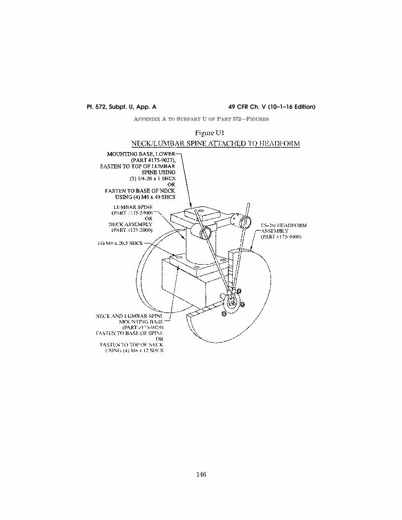
146
49 CFR Ch. V (10–1–16 Edition) Pt. 572, Subpt. U, App. A
APPENDIX A TO SUBPART U OF PART 572—FIGURES
VerDate Sep<11>2014 10:23 Mar 06, 2017 Jkt 238231 PO 00000 Frm 00156 Fmt 8010 Sfmt 8006 Y:\SGML\238231.XXX 238231 ER
14D
E06
.000
</G
PH
>
jsta
llwor
th o
n D
SK
7TP
TV
N1P
RO
D w
ith C
FR

147
Nat’l Highway Traffic Safety Admin., DOT Pt. 572, Subpt. U, App. A
VerDate Sep<11>2014 10:23 Mar 06, 2017 Jkt 238231 PO 00000 Frm 00157 Fmt 8010 Sfmt 8006 Y:\SGML\238231.XXX 238231 ER
16JN
08.0
06<
/GP
H>
jsta
llwor
th o
n D
SK
7TP
TV
N1P
RO
D w
ith C
FR

148
49 CFR Ch. V (10–1–16 Edition) Pt. 572, Subpt. U, App. A
VerDate Sep<11>2014 10:23 Mar 06, 2017 Jkt 238231 PO 00000 Frm 00158 Fmt 8010 Sfmt 8006 Y:\SGML\238231.XXX 238231 ER
14D
E06
.002
</G
PH
>
jsta
llwor
th o
n D
SK
7TP
TV
N1P
RO
D w
ith C
FR

149
Nat’l Highway Traffic Safety Admin., DOT Pt. 572, Subpt. U, App. A
VerDate Sep<11>2014 10:23 Mar 06, 2017 Jkt 238231 PO 00000 Frm 00159 Fmt 8010 Sfmt 8006 Y:\SGML\238231.XXX 238231 ER
14D
E06
.003
</G
PH
>E
R14
DE
06.0
04<
/GP
H>
jsta
llwor
th o
n D
SK
7TP
TV
N1P
RO
D w
ith C
FR

150
49 CFR Ch. V (10–1–16 Edition) Pt. 572, Subpt. U, App. A
VerDate Sep<11>2014 10:23 Mar 06, 2017 Jkt 238231 PO 00000 Frm 00160 Fmt 8010 Sfmt 8006 Y:\SGML\238231.XXX 238231 ER
14D
E06
.005
</G
PH
>
jsta
llwor
th o
n D
SK
7TP
TV
N1P
RO
D w
ith C
FR

151
Nat’l Highway Traffic Safety Admin., DOT Pt. 572, Subpt. U, App. A
VerDate Sep<11>2014 10:23 Mar 06, 2017 Jkt 238231 PO 00000 Frm 00161 Fmt 8010 Sfmt 8006 Y:\SGML\238231.XXX 238231 ER
14D
E06
.006
</G
PH
>
jsta
llwor
th o
n D
SK
7TP
TV
N1P
RO
D w
ith C
FR

152
49 CFR Ch. V (10–1–16 Edition) Pt. 572, Subpt. U, App. A
VerDate Sep<11>2014 10:23 Mar 06, 2017 Jkt 238231 PO 00000 Frm 00162 Fmt 8010 Sfmt 8006 Y:\SGML\238231.XXX 238231 ER
14D
E06
.007
</G
PH
>
jsta
llwor
th o
n D
SK
7TP
TV
N1P
RO
D w
ith C
FR

153
Nat’l Highway Traffic Safety Admin., DOT § 572.190
[71 FR 75331, Dec. 14, 2006, as amended at 73 FR 33921, June 16, 2008]
Subpart V—SID–IIsD Side Impact Crash Test Dummy, Small Adult Female
SOURCE: 71 FR 75370, Dec. 14, 2006, unless otherwise noted.
§ 572.190 Incorporated materials.
(a) The following materials are here-by incorporated into this Subpart by reference:
(1) A parts/drawing list entitled, ‘‘Parts/Drawings List, Part 572 Subpart V, SID–IIsD, July 1, 2008,’’
(2) A drawings and inspection pack-age entitled ‘‘Drawings and Specifica-tions for the SID–IIsD Small Female Crash Test Dummy, Part 572 Subpart V, July 1, 2008,’’ consisting of:
(i) Drawing No. 180–0000, SID–IIsD Complete Assembly;
(ii) Drawing No. 180–1000, 6 Axis Head Assembly;
(iii) Drawing No. 180–2000, Neck As-sembly;
VerDate Sep<11>2014 10:23 Mar 06, 2017 Jkt 238231 PO 00000 Frm 00163 Fmt 8010 Sfmt 8002 Y:\SGML\238231.XXX 238231 ER
14D
E06
.008
</G
PH
>
jsta
llwor
th o
n D
SK
7TP
TV
N1P
RO
D w
ith C
FR

154
49 CFR Ch. V (10–1–16 Edition) § 572.191
(iv) Drawing No. 180–3000, Upper Torso Assembly;
(v) Drawing No. 180–3005, Washer, Clamping;
(vi) Drawing No. 9000021, Screw, SHCS 3⁄8–16 × 1 NYLOK;
(vii) Drawing No. 900005, Screw, SHCS 1⁄4–20 × 5⁄8 NYLOK;
(viii) Drawing No. 180–4000, Lower Torso Assembly Complete;
(ix) Drawing No. 180–5000–1, Complete Leg Assembly, Left;
(x) Drawing No. 180–5000–2, Complete Leg Assembly, Right;
(xi) Drawing No. 180–6000–1, Arm As-sembly Left Molded;
(xii) Drawing No. 180–6000–2, Arm As-sembly Right Molded; and,
(xiii) Drawing No. 180–9000, SID–IIsD Headform Assembly.
(3) A procedures manual entitled, ‘‘Procedures for Assembly, Dis-assembly, and Inspection (PADI) of the SID–IIsD Side Impact Crash Test Dummy, July 1, 2008,’’ incorporated by reference in § 572.191;
(4) SAE Recommended Practice J211, Rev. Mar 95 ‘‘Instrumentation for Im-pact Tests—Part 1—Electronic Instru-mentation’’; and,
(5) SAE J1733 of 1994–12, ‘‘Sign Con-vention for Vehicle Crash Testing.’’
(b) The Director of the Federal Reg-ister approved the materials incor-porated by reference in accordance with 5 U.S.C. 552(a) and 1 CFR part 51. Copies of the materials may be in-spected at the Department of Transpor-tation, Docket Operations, Room W12– 140, 1200 New Jersey Avenue, SE., Washington, DC 20590, telephone (202) 366–9826, and at the National Archives and Records Administration (NARA), and in electronic format through Regu-lations.gov. For information on the availability and inspection of this ma-terial at NARA, call 202–741–6030, or go to: http://www.archives.gov/ federallregister/ codeloflfederallregulations/ ibrllocations.html. For information on the availability and inspection of this material at Regulations.gov, call 1–877– 378–5457, or go to: http:// www.regulations.gov.
(c) The incorporated materials are available as follows:
(1) The Parts/Drawings List, Part 572 Subpart V, SID–IIsD, July 1, 2008, re-
ferred to in paragraph (a)(1) of this sec-tion, the package entitled Drawings and Specifications for SID–IIsD Small Female Crash Test Dummy, Part 572 Subpart V, July 1, 2008, referred to in paragraph (a)(2) of this section, and the PADI document referred to in para-graph (a)(3) of this section, are avail-able in electronic format through www.Regulations.gov and in paper for-mat from Leet-Melbrook, Division of New RT, 18810 Woodfield Road, Gai-thersburg, MD 20879, (301) 670–0090.
(2) The SAE materials referred to in paragraphs (a)(4) and (a)(5) of this sec-tion are available from the Society of Automotive Engineers, Inc., 400 Com-monwealth Drive, Warrendale, PA 15096, telephone 1–877–606–7323.
[71 FR 75370, Dec. 14, 2006, as amended at 74 FR 29894, June 23, 2009]
§ 572.191 General description.
(a) The SID–IIsD Side Impact Crash Test Dummy, small adult female, is de-fined by:
(1) The drawings and specifications contained in the ‘‘Drawings and Speci-fications for SID–IIsD Small Female Crash Test Dummy, Part 572 Subpart V, July 1, 2008,’’ which includes the technical drawings and specifications described in Drawing 180–0000, the ti-tles of which are listed in Table A;
TABLE A
Component assembly Drawing number
6 Axis Head Assembly .................................. 180–1000 Neck Assembly .............................................. 180–2000 Upper Torso Assembly .................................. 180–3000 Clamping Washer .......................................... 180–3005 Lower Torso Assembly Complete ................. 180–4000 Complete Leg Assembly, Left ....................... 180–5000–1 Complete Leg Assembly, Right ..................... 180–5000–2 Arm Assembly Left Molded ........................... 180–6000–1 Arm Assembly Right Molded ......................... 180–6000–2
(2) The ‘‘Parts/Drawing List, Part 572 Subpart V, SID–IIsD,’’ dated July 1, 2008 and containing 7 pages,
(3) A listing of available transducers- crash test sensors for the SID–IIsD Side Impact Crash Test Dummy, 5th percentile adult female, is shown in drawing 180–0000 sheet 2 of 5, dated July 1, 2008,
(4) ‘‘Procedures for Assembly, Dis-assembly, and Inspection (PADI) of the
VerDate Sep<11>2014 10:23 Mar 06, 2017 Jkt 238231 PO 00000 Frm 00164 Fmt 8010 Sfmt 8002 Y:\SGML\238231.XXX 238231jsta
llwor
th o
n D
SK
7TP
TV
N1P
RO
D w
ith C
FR

155
Nat’l Highway Traffic Safety Admin., DOT § 572.193
SID–IIsD Side Impact Crash Test Dummy, July 1, 2008,’’ and,
(5) Sign convention for signal outputs reference document SAE J1733 Infor-mation Report, titled ‘‘Sign Conven-tion for Vehicle Crash Testing,’’ dated July 12, 1994, incorporated by reference in § 572.200(k).
(b) Exterior dimensions of the SID– IIsD Small Adult Female Side Impact Crash Test Dummy are shown in draw-ing 180–0000 sheet 3 of 5, dated July 1, 2008.
(c) Weights and center of gravity lo-cations of body segments are shown in drawing 180–0000 sheet 4 of 5, dated July 1, 2008.
(d) Adjacent segments are joined in a manner such that, except for contacts existing under static conditions, there is no additional contact between me-tallic elements of adjacent body seg-ments throughout the range of motion.
(e) The structural properties of the dummy are such that the dummy con-forms to this Subpart in every respect before use in any test similar to that set forth in Standard 214, Side Impact Protection (49 CFR 571.214).
[71 FR 75370, Dec. 14, 2006, as amended at 74 FR 29895, June 23, 2009]
§ 572.192 Head assembly. (a) The head assembly consists of the
head (180–1000) and a set of three (3) accelerometers in conformance with specifications in 49 CFR 572.200(d) and mounted as shown in drawing 180–0000 sheet 2 of 5. When tested to the proce-dure specified in paragraph (b) of this section, the head assembly shall meet performance requirements specified in paragraph (c) of this section.
(b) Test procedure. The head shall be tested according to the procedure spec-ified in 49 CFR 572.112(a).
(c) Performance criteria. (1) When the head assembly is
dropped from either the right or left lateral incline orientations in accord-ance with procedure in § 572.112(a), the measured peak resultant acceleration shall be between 115 g and 137 g;
(2) The resultant acceleration-time curve shall be unimodal to the extent that oscillations occurring after the main acceleration pulse shall not ex-ceed 15% (zero to peak) of the main pulse;
(3) The longitudinal acceleration vec-tor (anterior-posterior direction) shall not exceed 15 g.
§ 572.193 Neck assembly. (a) The neck assembly consists of
parts shown in drawing 180–2000. For purposes of this test, the neck assem-bly is mounted within the headform as-sembly (180–9000) as shown in Figure V1 in appendix A to this subpart. When subjected to the test procedure speci-fied in paragraph (b) of this section, the neck-headform assembly shall meet the performance requirements specified in paragraph (c) of this sec-tion.
(b) Test procedure. (1) Soak the assembly in a test envi-
ronment as specified in 49 CFR 572.200(j);
(2) Attach the neck-headform assem-bly, as shown in Figure V2–A or V2–B in appendix A to this subpart, to the 49 CFR Part 572 pendulum test fixture (Figure 22, 49 CFR 572.33) in either the left or right lateral impact orienta-tions, respectively, so that the midsagittal plane of the neck-headform assembly is vertical and at right angle (90 ±1 degrees) to the plane of motion of the pendulum longitudinal centerline;
(3) Release the pendulum from a height sufficient to achieve a velocity of 5.57 ±0.06 m/s measured at the center of the pendulum accelerometer, as shown in 49 CFR Part 572 Figure 15, at the instant the pendulum makes con-tact with the decelerating mechanism;
(4) The neck flexes without the neck- headform assembly making contact with any object;
(5) Time zero is defined as the time of initial contact between the pendulum mounted striker plate and the pen-dulum deceleration mechanism;
(6) Allow a period of at least thirty (30) minutes between successive tests on the same neck assembly.
(c) Performance Criteria. (1) The pendulum deceleration pulse
is characterized in terms of decrease in velocity as obtained by integrating the pendulum acceleration output from time zero:
Time(ms) Peakpendulumdelta- V(m/s)
10.0 ....................................................... ¥2.20 to ¥2.80 15.0 ....................................................... ¥3.30 to ¥4.10
VerDate Sep<11>2014 10:23 Mar 06, 2017 Jkt 238231 PO 00000 Frm 00165 Fmt 8010 Sfmt 8002 Y:\SGML\238231.XXX 238231jsta
llwor
th o
n D
SK
7TP
TV
N1P
RO
D w
ith C
FR

156
49 CFR Ch. V (10–1–16 Edition) § 572.194
1 Mx(oc) is the moment at occipital condyle (Newton-meters) and Fy is the lateral shear force (Newtons) measured by the load cell.
Time(ms) Peakpendulumdelta- V(m/s)
20.0 ....................................................... ¥4.40 to ¥5.40 25.0 ....................................................... ¥5.40 to ¥6.10 >25.0 <100 ........................................... ¥5.50 to ¥6.20
(2) The maximum translation-rota-tion of the midsagittal plane of the headform disk (180–9061 or 9062) in the lateral direction measured, with the rotation transducers specified in 49 CFR 572.200(e) shall be 71 to 81 degrees with respect to the longitudinal axis of the pendulum (see Figure V2–C in ap-pendix A to this subpart) occurring be-tween 50 and 70 ms from time zero;
(3) Peak occipital condyle moment shall not be higher than ¥36 Nm and not lower than ¥44 Nm. The moment measured by the upper neck load cell (Mx) shall be adjusted by the following formula: Mx(oc) 1= Mx + 0.01778Fy;
(4) The decaying moment shall cross the 0 Nm line after peak moment be-tween 102 ms-126 ms after time zero.
[71 FR 75370, Dec. 14, 2006, as amended at 74 FR 29895, June 23, 2009]
§ 572.194 Shoulder. (a) The shoulder structure is part of
the upper torso assembly shown in drawing 180–3000. For the shoulder im-pact test, the dummy is tested as a complete assembly (drawing 180–0000). The dummy is equipped with T1 lat-erally oriented accelerometer as speci-fied in 49 CFR 572.200(d), and deflection potentiometer as specified in 180–3881 configured for shoulder and installed as shown in drawing 180–0000 sheet 2 of 5. When subjected to the test procedure as specified in paragraph (b) of this sec-tion, the shoulder shall meet the per-formance requirements of paragraph (c) of this section.
(b) Test procedure. (1) Soak the dummy assembly (180–0000) in a test en-vironment as specified in 49 CFR 572.200(j).
(2) Seat the dummy, outfitted with the torso jacket (180–3450) and cotton underwear pants on a certification bench, specified in Figure V3 in appen-dix A to this subpart, the seat pan and the seatback surfaces of which are cov-
ered with a 2 mm thick PTFE (Teflon) sheet;
(3) Align the outermost portion of the pelvis flesh of the impacted side of the seated dummy tangent to a vertical plane located within 10 mm of the side edge of the bench as shown in Figure V4–A in appendix A to this sub-part, while the midsagittal plane of the dummy is in vertical orientation.
(4) Push the dummy at the knees and at mid-sternum of the upper torso with just sufficient horizontally oriented force towards the seat back until the back of the upper torso is in contact with the seat back.
(5) While maintaining the dummy’s position as specified in paragraphs (b)(3) and (4) of this section, the top of the shoulder rib mount (drawing 180– 3352) orientation in the fore-and-aft di-rection is 24.6 ±2.0 degrees relative to horizontal, as shown in Figure V4–B in appendix A to this subpart.
(6) Adjust orientation of the legs such that they are symmetrical about the mid-sagittal plane, the thighs touch the seat pan, the inner part of the right and left legs at the knees are as close as possible to each other, the heels touch the designated foot support surface and the feet are vertical and as close together as possible.
(7) Orient the arm to point forward at 90 ±2 degrees relative to the inferior-su-perior orientation of the upper torso spine box incline.
(8) The impactor is specified in 49 CFR 572.200(a).
(9) The impactor is guided, if needed, so that at contact with the dummy’s arm rotation centerline (ref. item 23 in drawing 180–3000) the impactor’s longi-tudinal axis is within ±1 degree of a horizontal plane and perpendicular to the midsagittal plane of the dummy. The centerpoint of the impactor face at contact is within 2 mm of the shoulder yoke assembly rotation centerline (drawing 180–3327), as shown in Figure V4–A in appendix A to this subpart.
(10) The dummy’s arm-shoulder is im-pacted at 4.3 ±0.1 m/s with the impactor meeting the alignment and contact point requirements of paragraph (b)(9) of this section.
(11) Allow a period of at least thirty (30) minutes between successive tests of the same shoulder assembly.
VerDate Sep<11>2014 10:23 Mar 06, 2017 Jkt 238231 PO 00000 Frm 00166 Fmt 8010 Sfmt 8002 Y:\SGML\238231.XXX 238231jsta
llwor
th o
n D
SK
7TP
TV
N1P
RO
D w
ith C
FR

157
Nat’l Highway Traffic Safety Admin., DOT § 572.195
(c) Performance criteria. (1) While the impactor is in contact
with the dummy’s arm, the shoulder shall compress not less than 28 mm and not more than 37 mm measured by the potentiometer specified in (a);
(2) Peak lateral acceleration of the upper spine (T1) shall not be less than 17 g and not more than 22 g;
(3) Peak impactor acceleration shall be not less than 13 g and not more than 18 g.
[71 FR 75370, Dec. 14, 2006, as amended at 74 FR 29895, June 23, 2009]
§ 572.195 Thorax with arm.
(a) The thorax is part of the upper torso assembly shown in drawing 180– 3000. For the thorax with arm impact test, the dummy is tested as a com-plete assembly (drawing 180–0000). The dummy’s thorax is equipped with T1 and T12 laterally oriented accelerometers as specified in 49 CFR 572.200(d), and deflection potentiom-eters for the thorax and shoulder as specified in 180–3881, installed as shown in drawing 180–0000 sheet 2 of 5. When subjected to the test procedure as spec-ified in paragraph (b) of this section, the thorax shall meet performance re-quirements of paragraph (c) of this sec-tion.
(b) Test procedure. (1) Soak the dummy assembly (180–0000) in a test en-vironment as specified in 49 CFR 572.200(j).
(2) Seat the dummy, outfitted with the torso jacket (180–3450) and cotton underwear pants on a certification bench, specified in Figure V3, the seat pan and the seatback surfaces of which are covered with a 2-mm-thick PTFE (Teflon) sheet.
(3) Align the outermost portion of the pelvis flesh of the impacted side of the seated dummy tangent to a vertical plane located within 10 mm of the side edge of the bench as shown in Figure V5–A, while the midsagittal plane of the dummy is in vertical ori-entation.
(4) Push the dummy at the knees and at mid-sternum of the upper torso with just sufficient horizontally oriented force towards the seat back until the back of the upper torso is in contact with the seat back.
(5) While maintaining the dummy’s position as specified in paragraphs (b)(3) and (4) of this section, the top of the shoulder rib mount (drawing 180– 3352) orientation in the fore-and-aft di-rection is 24.6 ±2.0 degrees relative to horizontal as shown in Figure V5–B in appendix A to this subpart.
(6) Adjust orientation of the legs such that they are symmetrical about the mid-sagittal plane, the thighs touch the seat pan, the inner part of the right and left legs at the knees are as close as possible to each other, the heels touch the designated foot support surface and the feet are vertical and as close together as possible.
(7) Orient the arm downward to the lowest detent such that the longitu-dinal centerline of the arm is parallel to the inferior-superior orientation of the spine box.
(8) The impactor is specified in 49 CFR 572.200(a).
(9) The impactor is guided, if needed, so that at contact with the dummy’s arm, its longitudinal axis is within ±1 degree of a horizontal plane and per-pendicular to the midsagittal plane of the dummy. The centerpoint of the im-pactor face is within 2 mm of the vertical midpoint of the second tho-racic rib and coincident with a line parallel to the seat back incline pass-ing through the center of the shoulder yoke assembly arm rotation pivot (drawing 180–3327), as shown in Figure V5–A in appendix A to this subpart.
(10) The dummy’s arm is impacted at 6.7 ±0.1 m/s.
(11) Time zero is defined as the time of contact between the impact probe and the arm.
(12) Allow a period of at least thirty (30) minutes between successive tests of the same thorax assembly.
(c) Performance criteria. (1) While the impactor is in contact
with the dummy’s arm, the thoracic ribs and the shoulder shall conform to the following range of deflections:
(i) Shoulder not less than 31 mm and not more than 40 mm;
(ii) Upper thorax rib not less than 25 mm and not more than 32 mm;
(iii) Middle thorax rib not less than 30 mm and not more than 36 mm;
(iv) Lower thorax rib not less than 32 mm and not more than 38 mm;
VerDate Sep<11>2014 10:23 Mar 06, 2017 Jkt 238231 PO 00000 Frm 00167 Fmt 8010 Sfmt 8002 Y:\SGML\238231.XXX 238231jsta
llwor
th o
n D
SK
7TP
TV
N1P
RO
D w
ith C
FR

158
49 CFR Ch. V (10–1–16 Edition) § 572.196
(2) Peak lateral acceleration of the upper spine (T1) shall not be less than 34 g and not more than 43 g, and the lower spine (T12) not less than 29 g and not more than 37 g;
(3) Peak impactor acceleration after 5 ms after time zero shall be not less than 30 g and not more than 36 g.
[71 FR 75370, Dec. 14, 2006, as amended at 74 FR 29895, June 23, 2009]
§ 572.196 Thorax without arm. (a) The thorax is part of the upper
torso assembly shown in drawing 180– 3000. For this thorax test, the dummy is tested as a complete assembly (draw-ing 180–0000) with the arm (180–6000) on the impacted side removed. The dum-my’s thorax is equipped with T1 and T12 laterally oriented accelerometers as specified in 49 CFR 572.200(d) and with deflection potentiometers for the thorax as specified in drawing 180–3881, installed as shown in drawing 180–0000 sheet 2 of 5. When subjected to the test procedure specified in paragraph (b) of this section, the thorax shall meet the performance requirements set forth in paragraph (c) of this section.
(b) Test procedure. (1) Soak the dummy assembly (180–0000) in a test en-vironment as specified in 49 CFR 572.200(j).
(2) Seat the dummy, outfitted with the torso jacket (180–3450) and cotton underwear pants on a calibration bench, specified in Figure V3 in appen-dix A to this subpart, the seat pan and the seatback surfaces of which are cov-ered with a 2-mm-thick PTFE (Teflon) sheet.
(3) Align the outermost portion of the pelvis flesh of the impacted side of the seated dummy tangent to a vertical plane located within 10 mm of the side edge of the bench as shown in Figure V6–A, while the midsagittal plane of the dummy is in vertical ori-entation.
(4) Push the dummy at the knees and at mid-sternum of the upper torso with just sufficient horizontally oriented force towards the seat back until the back of the upper torso is in contact with the seat back.
(5) While maintaining the dummy’s position as specified in paragraphs (b)(3) and (4) of this section, the top of the shoulder rib mount (drawing 180–
3352) orientation in the fore-and-aft di-rection is 24.6 ±2.0 degrees relative to horizontal, as shown in Figure V6–B in appendix A to this subpart.
(6) Adjust orientation of the legs such that they are symmetrical about the mid-sagittal plane, the thighs touch the seat pan, the inner part of the right and left legs at the knees are as close as possible to each other, the heels touch the designated foot support surface and the feet are vertical and as close together as possible.
(7) The impactor is specified in 49 CFR 572.200(a).
(8) The impactor is guided, if needed, so that at contact with the thorax, its longitudinal axis is within 1 degree of a horizontal plane and perpendicular to the midsagittal plane of the dummy. The centerpoint of the impactor face is within 2 mm of the vertical midpoint of the second thorax rib and coincident with a line parallel to the seat back in-cline passing through the center of the shoulder yoke assembly arm rotation pivot (drawing 180–3327), as shown in Figure V6–A in appendix A to this sub-part.
(9) The dummy’s thorax is impacted at 4.3 ±0.1 m/s.
(10) Allow a period of at least thirty (30) minutes between successive tests of the same thorax assembly.
(c) Performance criteria. (1) While the impactor is in contact
with the dummy’s thorax, the ribs shall conform to the following range of deflections:
(i) Upper thorax rib not less than 32 mm and not more than 40 mm;
(ii) Middle thorax rib not less than 39 mm and not more than 45 mm;
(iii) Lower thorax rib not less than 35 mm and not more than 43 mm;
(2) Peak acceleration of the upper spine (T1) shall not be less than 13 g and not more than 17 g and the lower spine (T12) not less than 7 g and not more than 11 g;
(3) Peak impactor acceleration shall not be less than 14 g and not more than 18 g.
[71 FR 75370, Dec. 14, 2006, as amended at 74 FR 29895, June 23, 2009]
§ 572.197 Abdomen. (a) The abdomen assembly is part of
the upper torso assembly (180–3000) and
VerDate Sep<11>2014 10:23 Mar 06, 2017 Jkt 238231 PO 00000 Frm 00168 Fmt 8010 Sfmt 8002 Y:\SGML\238231.XXX 238231jsta
llwor
th o
n D
SK
7TP
TV
N1P
RO
D w
ith C
FR

159
Nat’l Highway Traffic Safety Admin., DOT § 572.198
is represented by two ribs (180–3368) and two linear deflection potentiometers (180–3881). The abdomen test is con-ducted on the complete dummy assem-bly (180–0000) with the arm (180–6000) on the impacted side removed. The dummy is equipped with a lower spine laterally oriented accelerometer as specified in 49 CFR 572.200(d) and de-flection potentiometers specified in drawing 180–3881, installed as shown in sheet 2 of drawing 180–0000. When sub-jected to the test procedure as speci-fied in paragraph (b) of this section, the abdomen shall meet performance requirements of paragraph (c) of this section.
(b) Test procedure. (1) Soak the dummy assembly (180–0000) in a test en-vironment as specified in 49 CFR 572.200(j).
(2) Seat the dummy, outfitted with the torso jacket (180–3450) and cotton underwear pants on a calibration bench, specified in Figure V3, the seat pan and the seatback surfaces of which are covered with a 2 mm thick PTFE (Teflon) sheet.
(3) Align the outermost portion of the pelvis flesh of the impacted side of the seated dummy tangent to a vertical plane located within 10 mm of the side edge of the bench as shown in Figure V7–A in Appendix A to this sub-part, while the midsagittal plane of the dummy is in vertical orientation.
(4) Push the dummy at the knees and at mid-sternum of the upper torso with just sufficient horizontally oriented force towards the seat back until the back of the upper torso is in contact with the seat back.
(5) While maintaining the dummy’s position as specified in paragraph (b)(3) and (4) of this section, the top of the shoulder rib mount (drawing 180–3352) orientation in the fore-and-aft direc-tion is 24.6 ±2.0 degrees relative to hori-zontal, as shown in Figure V7–B in ap-pendix A to this subpart);
(6) Adjust orientation of the legs such that they are symmetrical about the mid-sagittal plane, the thighs touch the seat pan, the inner part of the right and left legs at the knees are as close as possible to each other, the heels touch the designated foot support surface and the feet are vertical and as close together as possible;
(7) The impactor is specified in 49 CFR 572.200(b);
(8) The impactor is guided, if needed, so that at contact with the abdomen, its longitudinal axis is within ±1 degree of a horizontal plane and perpendicular to the midsagittal plane of the dummy and the centerpoint of the impactor’s face is within 2 mm of the vertical mid-point between the two abdominal ribs and coincident with a line parallel to the seat back incline passing through the center of the shoulder yoke assem-bly arm rotation pivot (drawing 180– 3327), as shown in Figure V7–A in ap-pendix A to this subpart;
(9) The dummy’s abdomen is im-pacted at 4.3 ±0.1 m/s.
(10) Allow a period of at least thirty (30) minutes between successive tests of the same abdomen assembly.
(c) Performance criteria. (1) While the impact probe is in contact with the dummy’s abdomen, the deflection of the upper abdominal rib shall be not less than 36 mm and not more than 47 mm, and the lower abdominal rib not less than 33 mm and not more than 44 mm.
(2) Peak acceleration of the lower spine (T12) laterally oriented acceler-ometer shall be not less than 9 g and not more than 14 g;
(3) Peak impactor acceleration shall be not less than 12 g and not more than 16 g.
[71 FR 75370, Dec. 14, 2006, as amended at 74 FR 29896, June 23, 2009]
§ 572.198 Pelvis acetabulum.
(a) The acetabulum is part of the lower torso assembly shown in drawing 180–4000. The acetabulum test is con-ducted by impacting the side of the lower torso of the assembled dummy (drawing 180–0000). The dummy is equipped with a laterally oriented pel-vis accelerometer as specified in 49 CFR 572.200(d), acetabulum load cell SA572–S68, mounted as shown in sheet 2 of 5 of drawing 180–0000, and an unused and certified pelvis plug (180–4450). When subjected to the test procedure as specified in paragraph (b) of this sec-tion, the pelvis shall meet performance requirements of paragraph (c) of this section.
VerDate Sep<11>2014 10:23 Mar 06, 2017 Jkt 238231 PO 00000 Frm 00169 Fmt 8010 Sfmt 8002 Y:\SGML\238231.XXX 238231jsta
llwor
th o
n D
SK
7TP
TV
N1P
RO
D w
ith C
FR

160
49 CFR Ch. V (10–1–16 Edition) § 572.199
(b) Test procedure. (1) Soak the dummy assembly (180–0000) in a test en-vironment as specified in 49 CFR 572.200(j).
(2) Seat the dummy, without the torso jacket (180–3450) and without cot-ton underwear pants, as shown in Fig-ure V8–A in appendix A to this subpart, on a calibration bench, specified in Figure V3 in appendix A to this sub-part, with the seatpan and the seatback surfaces covered with a 2- mm-thick PTFE (Teflon) sheet;
(3) Align the outermost portion of the pelvis flesh of the impacted side of the seated dummy tangent to a vertical plane located within 10 mm of the side edge of the bench as shown in Figure V8–A in appendix A to this sub-part, while the midsagittal plane of the dummy is in vertical orientation.
(4) Push the dummy at the knees and at mid-sternum of the upper torso with just sufficient horizontally oriented force towards the seat back until the back of the upper torso is in contact with the seat back.
(5) While maintaining the dummy’s position as specified in paragraphs (b)(3) and (4) of this section, the top of the shoulder rib mount (drawing 180– 3352) orientation in the fore-and-aft di-rection is 24.6 ±1.0 degrees relative to horizontal, as shown in Figure V8–B in appendix A to this subpart;
(6) Adjust orientation of the legs such that they are symmetrical about the mid-sagittal plane, the thighs touch the seat pan, the inner part of the right and left legs at the knees are as close as possible to each other, the heels touch the designated foot support surface and the feet are vertical and as close together as possible.
(7) Rotate the arm downward to the lowest detent such that the longitu-dinal centerline of the arm is parallel to the inferior-superior orientation of the spine box.
(8) The impactor is specified in 49 CFR 572.200(a).
(9) The impactor is guided, if needed, so that at contact with the pelvis, its longitudinal axis is within ±1 degree of a horizontal plane and perpendicular to the midsagittal plane of the dummy. The centerpoint of the impactor’s face is in line within 2 mm of the longitu-dinal centerline of the 1⁄4-20x1⁄2 flat
head cap screw through the center of the acetabulum load cell (SA572–S68), as shown in Figure V8–A in appendix A to this subpart;
(10) The dummy’s pelvis is impacted at the acetabulum at 6.7 ±0.1 m/s.
(11) Time zero is defined as the time of contact between the impact probe and the pelvis plug.
(12) Allow a period of at least 120 minutes between successive tests of the same pelvis assembly.
(c) Performance criteria. While the im-pactor is in contact with the pelvis:
(1) Peak acceleration of the impactor is not less than 38 g and not more than 47 g;
(2) Peak lateral acceleration of the pelvis after 6 ms after time zero is not less than 34 g and not more than 42 g;
(3) Peak acetabulum force is not less than 3.60 kN and not more than 4.30 kN.
[71 FR 75370, Dec. 14, 2006, as amended at 74 FR 29896, June 23, 2009]
§ 572.199 Pelvis iliac. (a) The iliac is part of the lower torso
assembly shown in drawing 180–4000. The iliac test is conducted by impact-ing the side of the lower torso of the assembled dummy (drawing 180–0000). The dummy is equipped with a lat-erally oriented pelvis accelerometer as specified in 49 CFR 572.200(d), and iliac wing load cell SA572–S66, mounted as shown in sheet 2 of 5 of drawing 180– 0000. When subjected to the test proce-dure as specified in paragraph (b) of this section, the pelvis shall meet per-formance requirements of paragraph (c) of this section.
(b) Test procedure. (1) Soak the dummy assembly (180–0000) in a test en-vironment as specified in 49 CFR 572.200(j).
(2) Seat the dummy, without the torso jacket and without cotton under-wear pants, as shown in Figure V9–A in appendix A to this subpart, on a flat, rigid, horizontal surface covered with a 2-mm-thick PTFE (Teflon) sheet.
(3) The legs are outstretched in front of the dummy such that they are sym-metrical about the midsagittal plane, the thighs touch the seated surface, the inner part of the right and left legs at the knees are as close as possible to each other, and the feet are in full
VerDate Sep<11>2014 10:23 Mar 06, 2017 Jkt 238231 PO 00000 Frm 00170 Fmt 8010 Sfmt 8002 Y:\SGML\238231.XXX 238231jsta
llwor
th o
n D
SK
7TP
TV
N1P
RO
D w
ith C
FR

161
Nat’l Highway Traffic Safety Admin., DOT § 572.200
dorsiflexion and as close together as possible.
(4) Orient the arm downward to the lowest detent such that the longitu-dinal centerline of the arm is parallel to the inferior-superior orientation of the spine box.
(5) The midsagittal plane of the dummy is vertical, and superior sur-face of the lower half neck assembly load cell replacement (180–3815) in the lateral direction is within ±1 degree relative to the horizontal as shown in Figure V9–A.
(6) While maintaining the dummy’s position as specified in paragraphs (b)(3), (4) and (5) of this section, the top of the shoulder rib mount (180–3352) ori-entation in the fore-and-aft direction is within ±1.0 degree relative to hori-zontal as shown in Figure V9–B in Ap-pendix A to this subpart.
(7) The pelvis impactor is specified in 49 CFR 572.200(c).
(8) The dummy is positioned with re-spect to the impactor such that the longitudinal centerline of the impact probe is in line with the longitudinal centerline of the iliac load cell access hole, and the 88.9 mm dimension of the probe’s impact surface is aligned hori-zontally.
(9) The impactor is guided, if needed, so that at contact with the pelvis, the longitudinal axis of the impactor is within ±1 degree of a horizontal plane and perpendicular to the midsagittal plane of the dummy.
(10) The dummy’s pelvis is impacted at the iliac location at 4.3±0.1 m/s.
(11) Allow a period of at least 120 minutes between successive tests of the same pelvis assembly.
(c) Performance criteria. While the im-pactor is in contact with the pelvis:
(1) Peak acceleration of the impactor is not less than 36 g and not more than 45 g;
(2) Peak acceleration of the pelvis is not less than 28 g and not more than 39 g;
(3) Peak iliac force is not less than 4.10 kN and not more than 5.10 kN.
[71 FR 75370, Dec. 14, 2006, as amended at 74 FR 29896, June 23, 2009]
§ 572.200 Instrumentation and test conditions.
(a) The test probe for shoulder, lat-eral thorax, and pelvis-acetabulum im-pact tests is the same as that specified in 49 CFR 572.137(a) except that its im-pact face diameter is 120.70 ±0.25 mm and it has a minimum mass moment of inertia of 3646 kg-cm2.
(b) The test probe for the lateral ab-domen impact test is the same as that specified in 572.137(a) except that its impact face diameter is 76.20 ±0.25 mm and it has a minimum mass moment of inertia of 3646 kg-cm2.
(c) The test probe for the pelvis-iliac impact tests is the same as that speci-fied in 49 CFR 572.137(a) except that it has a rectangular flat impact surface 50.8 × 88.9 mm for a depth of at least 76 mm and a minimum mass moment of inertia of 5000 kg-cm2.
(d) Accelerometers for the head, the thoracic spine, and the pelvis conform to specifications of SA572–S4.
(e) Rotary potentiometers for the neck-headform assembly conform to SA572–S51.
(f) Instrumentation and sensors con-form to the Recommended Practice SAE J–211 (March 1995), Instrumenta-tion for Impact Test, unless noted oth-erwise.
(g) All instrumented response signal measurements shall be treated to the following specifications:
(1) Head acceleration—digitally fil-tered CFC 1000;
(2) Neck-headform assembly trans-lation-rotation—digitally filtered CFC 60;
(3) Neck pendulum, T1 and T12 tho-racic spine and pelvis accelerations— digitally filtered CFC 180;
(4) Neck forces (for the purpose of oc-cipital condyle calculation) and mo-ments—digitally filtered at CFC 600;
(5) Pelvis, shoulder, thorax and abdo-men impactor accelerations—digitally filtered CFC 180;
(6) Acetabulum and iliac wings forces—digitally filtered at CFC 600;
(7) Shoulder, thorax, and abdomen deflection—digitally filtered CFC 600.
(h) Mountings for the head, thoracic spine and pelvis accelerometers shall have no resonant frequency within a range of 3 times the frequency range of the applicable channel class;
VerDate Sep<11>2014 10:23 Mar 06, 2017 Jkt 238231 PO 00000 Frm 00171 Fmt 8010 Sfmt 8002 Y:\SGML\238231.XXX 238231jsta
llwor
th o
n D
SK
7TP
TV
N1P
RO
D w
ith C
FR
162
49 CFR Ch. V (10–1–16 Edition) § 572.200
(i) Leg joints of the test dummy are set at the force between 1 to 2 g, which just support the limb’s weight when the limbs are extended horizontally forward. The force required to move a limb segment does not exceed 2 g throughout the range of the limb mo-tion.
(j) Performance tests are conducted, unless specified otherwise, at any tem-perature from 20.6 to 22.2 degrees C. (69 to 72 degrees F.) and at any relative
humidity from 10% to 70% after expo-sure of the dummy to those conditions for a period of 4 hours.
(k) Coordinate signs for instrumenta-tion polarity shall conform to the Sign Convention For Vehicle Crash Testing, Surface Vehicle Information Report, SAE J1733, 1994–12 (refer to § 572.191(a)(5)).
[71 FR 75370, Dec. 14, 2006, as amended at 74 FR 29896, June 23, 2009]
VerDate Sep<11>2014 10:23 Mar 06, 2017 Jkt 238231 PO 00000 Frm 00172 Fmt 8010 Sfmt 8002 Y:\SGML\238231.XXX 238231jsta
llwor
th o
n D
SK
7TP
TV
N1P
RO
D w
ith C
FR

163
Nat’l Highway Traffic Safety Admin., DOT Pt. 572, Subpt. V, App. A
APPENDIX A TO SUBPART V OF PART 572—FIGURES
VerDate Sep<11>2014 10:23 Mar 06, 2017 Jkt 238231 PO 00000 Frm 00173 Fmt 8010 Sfmt 8006 Y:\SGML\238231.XXX 238231 ER
14D
E06
.009
</G
PH
>
jsta
llwor
th o
n D
SK
7TP
TV
N1P
RO
D w
ith C
FR

164
49 CFR Ch. V (10–1–16 Edition) Pt. 572, Subpt. V, App. A
VerDate Sep<11>2014 10:23 Mar 06, 2017 Jkt 238231 PO 00000 Frm 00174 Fmt 8010 Sfmt 8006 Y:\SGML\238231.XXX 238231 ER
14D
E06
.010
</G
PH
>
jsta
llwor
th o
n D
SK
7TP
TV
N1P
RO
D w
ith C
FR

165
Nat’l Highway Traffic Safety Admin., DOT Pt. 572, Subpt. V, App. A
VerDate Sep<11>2014 10:23 Mar 06, 2017 Jkt 238231 PO 00000 Frm 00175 Fmt 8010 Sfmt 8006 Y:\SGML\238231.XXX 238231 ER
14D
E06
.011
</G
PH
>
jsta
llwor
th o
n D
SK
7TP
TV
N1P
RO
D w
ith C
FR

166
49 CFR Ch. V (10–1–16 Edition) Pt. 572, Subpt. V, App. A
VerDate Sep<11>2014 10:23 Mar 06, 2017 Jkt 238231 PO 00000 Frm 00176 Fmt 8010 Sfmt 8006 Y:\SGML\238231.XXX 238231 ER
14D
E06
.012
</G
PH
>
jsta
llwor
th o
n D
SK
7TP
TV
N1P
RO
D w
ith C
FR
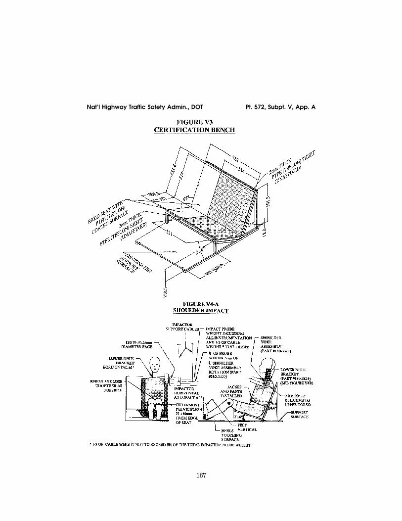
167
Nat’l Highway Traffic Safety Admin., DOT Pt. 572, Subpt. V, App. A
VerDate Sep<11>2014 10:23 Mar 06, 2017 Jkt 238231 PO 00000 Frm 00177 Fmt 8010 Sfmt 8006 Y:\SGML\238231.XXX 238231 ER
14D
E06
.013
</G
PH
>E
R23
JN09
.005
</G
PH
>
jsta
llwor
th o
n D
SK
7TP
TV
N1P
RO
D w
ith C
FR

168
49 CFR Ch. V (10–1–16 Edition) Pt. 572, Subpt. V, App. A
VerDate Sep<11>2014 10:23 Mar 06, 2017 Jkt 238231 PO 00000 Frm 00178 Fmt 8010 Sfmt 8006 Y:\SGML\238231.XXX 238231 ER
14D
E06
.015
</G
PH
>E
R14
DE
06.0
16<
/GP
H>
jsta
llwor
th o
n D
SK
7TP
TV
N1P
RO
D w
ith C
FR

169
Nat’l Highway Traffic Safety Admin., DOT Pt. 572, Subpt. V, App. A
VerDate Sep<11>2014 10:23 Mar 06, 2017 Jkt 238231 PO 00000 Frm 00179 Fmt 8010 Sfmt 8006 Y:\SGML\238231.XXX 238231 ER
14D
E06
.017
</G
PH
>E
R14
DE
06.0
18<
/GP
H>
jsta
llwor
th o
n D
SK
7TP
TV
N1P
RO
D w
ith C
FR

170
49 CFR Ch. V (10–1–16 Edition) Pt. 572, Subpt. V, App. A
VerDate Sep<11>2014 10:23 Mar 06, 2017 Jkt 238231 PO 00000 Frm 00180 Fmt 8010 Sfmt 8006 Y:\SGML\238231.XXX 238231 ER
14D
E06
.019
</G
PH
>E
R14
DE
06.0
20<
/GP
H>
jsta
llwor
th o
n D
SK
7TP
TV
N1P
RO
D w
ith C
FR

171
Nat’l Highway Traffic Safety Admin., DOT Pt. 572, Subpt. V, App. A
VerDate Sep<11>2014 10:23 Mar 06, 2017 Jkt 238231 PO 00000 Frm 00181 Fmt 8010 Sfmt 8006 Y:\SGML\238231.XXX 238231 ER
14D
E06
.021
</G
PH
>E
R14
DE
06.0
22<
/GP
H>
jsta
llwor
th o
n D
SK
7TP
TV
N1P
RO
D w
ith C
FR

172
49 CFR Ch. V (10–1–16 Edition) Pt. 572, Subpt. V, App. A
VerDate Sep<11>2014 10:23 Mar 06, 2017 Jkt 238231 PO 00000 Frm 00182 Fmt 8010 Sfmt 8006 Y:\SGML\238231.XXX 238231 ER
14D
E06
.023
</G
PH
>E
R23
JN09
.006
</G
PH
>
jsta
llwor
th o
n D
SK
7TP
TV
N1P
RO
D w
ith C
FR

173
Nat’l Highway Traffic Safety Admin., DOT § 573.1
[71 FR 75370, Dec. 14, 2006, as amended at 74 FR 29896, June 23, 2009]
PART 573—DEFECT AND NON-COMPLIANCE RESPONSIBILITY AND REPORTS
Sec. 573.1 Scope. 573.2 Purpose. 573.3 Application. 573.4 Definitions. 573.5 Defect and noncompliance responsi-
bility. 573.6 Defect and noncompliance information
report. 573.7 Quarterly reports. 573.8 Lists of purchasers, owners, dealers,
distributors, lessors and lessees. 573.9 Address for submitting required re-
ports and other information. 573.10 Reporting the sale or lease of defec-
tive or noncompliant tires. 573.11 Prohibition on sale or lease of new
defective and noncompliant motor vehi-cles and items of replacement equip-ment.
573.12 Prohibition on sale or lease of new and used defective and noncompliant motor vehicle equipment.
573.13 Reimbursement for prenotification remedies.
573.14 Accelerated remedy program. 573.15 Public availability of motor vehicle
recall information.
573.16 Reporting bankruptcy petition.
AUTHORITY: 49 U.S.C. 30102, 30103, 30116– 30121, 30166, Pub. L. 112–141, 126 Stat. 405; del-egation of authority at 49 CFR 1.95 and 49 CFR 501.8.
SOURCE: 43 FR 60169, Dec. 26, 1978, unless otherwise noted.
§ 573.1 Scope. This part: (a) Sets forth the responsibilities
under 49 U.S.C. 30116–30121 of manufac-turers of motor vehicles and motor ve-hicle equipment with respect to safety- related defects and noncompliances with Federal motor vehicle safety standards in motor vehicles and items of motor vehicle equipment; and
(b) Specifies requirements for— (1) Manufacturers to maintain lists of
owners, purchasers, dealers, and dis-tributors notified of defective and non-complying motor vehicles and motor vehicle original and replacement equip-ment,
(2) Reporting to the National High-way Traffic Safety Administration (NHTSA) defects in motor vehicles and motor vehicle equipment and non-compliances with motor vehicle safety standards prescribed under part 571 of this chapter, and
VerDate Sep<11>2014 10:23 Mar 06, 2017 Jkt 238231 PO 00000 Frm 00183 Fmt 8010 Sfmt 8010 Y:\SGML\238231.XXX 238231 ER
23JN
09.0
07<
/GP
H>
jsta
llwor
th o
n D
SK
7TP
TV
N1P
RO
D w
ith C
FR