part 2 - works requirements
TRANSCRIPT

PART 2 - WORKS REQUIREMENTS

Section VII. Schedule of Prices
Description Amount %
Section A - Design
Bill №: 01 ‐ HOLISTIC DETAILED DESIGN – Architectural Design, Structural Design, Mechanical, Electrical Power, Electronic, Data, IT, PABX, PA Systems, Audio Visual Display, Name Boards, Curtains, Hospital HVAC. Piped Medical Gas, Un-interrupted Power Supply Systems, Emergency Generators, Potable Water Storages, Solar Power Systems on Roofs, All Connections & Terminations to Public Utilities, Bio Hazardous waste Disposal, by Sterilization or methods as per the Maldives Environmental Protection Agency’s Guidelines and Law & Land Scaping & Fire Stopping & Alarm System
Section B - Construction
Bill №: 01 ‐ PRELIMINARIES – INCLUDES SITE CLEARING, CLEAN OUT & ALL WASTE DISPOSAL ON HAND OVER
Bill №: 02 ‐ EXCAVATION AND FILLING
Bill №: 03 – DEMOLITION WORKS – IF ANY BUILDINGS ON SITE
Bill №: 04 ‐ INSITU CONCRETE WORKS
Bill №: 05 ‐ MASONRY
Bill №: 06 ‐ STRUCTURAL METAL WORKS
Bill №: 07 ‐ CARPENTRY
Bill №: 08 ‐ ROOFING
Bill №: 09 ‐ PROPRIETARY LININGS AND PARTITIONS
Bill №: 10 ‐ WINDOWS, SCREENS & LIGHTS
Bill №: 11 ‐ DOORS, SHUTTERS & HATCHES
Bill №: 12 ‐ STAIRS, WALKWAYS AND BALUSTRADES
Bill №: 13 ‐ FLOORING AND TILING
Bill №: 14 ‐ CONCEALED CEILING
Bill №: 15 ‐ PAINTING AND DECORATIONS
Bill №: 16 ‐ HYDRAULICS AND DRAINAGE
Bill №: 17 ‐ MECHANICAL & ELECTRICAL SERVICES
Bill №: 18 ‐ ELECTRONIC, IT, PABX, PA, DATA, AUDIO VISUAL
Bill №: 19 ‐ LIFTS
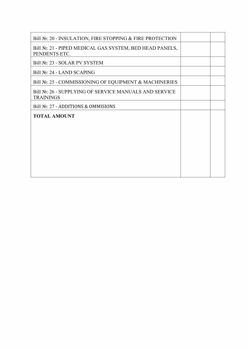
Bill №: 20 ‐ INSULATION, FIRE STOPPING & FIRE PROTECTION
Bill №: 21 ‐ PIPED MEDICAL GAS SYSTEM, BED HEAD PANELS, PENDENTS ETC.
Bill №: 23 ‐ SOLAR PV SYSTEM
Bill №: 24 ‐ LAND SCAPING
Bill №: 25 ‐ COMMISSIONING OF EQUIPMENT & MACHINERIES
Bill №: 26 ‐ SUPPLYING OF SERVICE MANUALS AND SERVICE TRAININGS
Bill №: 27 ‐ ADDITIONS & OMMISIONS
TOTAL AMOUNT

Section VIII. Employer’s Requirement
PART 2 - Works Requirements ........................................................................................... 93
A. Preliminaries ............................................................................................................ 101 1. Project Background ................................................................................................................ 101
2. Scope of Works ...................................................................................................................... 101
3. Visiting site ............................................................................................................................ 103
4. The existing environment ....................................................................................................... 103
5. Information of existing building ............................................................................................. 104
6. Contractual requirements ....................................................................................................... 104
7. Management of the Works ..................................................................................................... 105
8. Quality standards/control ....................................................................................................... 107
9. Health and Safety ................................................................................................................... 109
10. Site rules ................................................................................................................................. 109
11. Handovers............................................................................................................................... 111
12. Rectification period ................................................................................................................ 112
B. TECHNICAL SPECIFICATION – General Works ............................................ 114 1. SITE WORKS ............................................................................................................................ 114
2. CONCRETE WORKS ................................................................................................................. 118
3. CONCRETE FORMWORK ......................................................................................................... 125
4. STEEL REINFORCEMENT ......................................................................................................... 128
5. WATER PROOFING .................................................................................................................. 129
6. EMBEDDED DAMPPROOF MEMBRANE .................................................................................. 131
7. STRUCTURAL STEEL ................................................................................................................ 132
8. MASONRY ............................................................................................................................... 136
9. PLASTERING ............................................................................................................................ 139
10. CARPENTRY AND JOINERY ...................................................................................................... 143
11. ALUMINIUM DOORS AND WINDOWS .................................................................................... 145
12. METAL WALL PANELS ............................................................................................................. 150
13. ROOFING ................................................................................................................................ 157
14. FINISHES ................................................................................................................................. 160
15. PAINTING ................................................................................................................................ 167
C. TECHINCAL SPECIFICATION – Services ........................................................ 174

1. LIFT SPECIFICATION .............................................................................................................. 174
1.1 Scope of Work ........................................................................................................................... 174
1.2 General Requirements ............................................................................................................... 175
1.3 Regulations and Standards ........................................................................................................ 176
1.4 System Description .................................................................................................................... 176
1.5 EQUIPMENT ............................................................................................................................ 177
1.5.2 CAR FRAMES AND GUIDE SHOES .................................................................................. 178
1.5.3 SAFETY GEAR(S) AND OVERSPEED GOVERNOR(S)................................................... 179
1.5.4 COUNTERWEIGHTS ........................................................................................................... 179
1.5.5 CARS ..................................................................................................................................... 180
1.5.6 INSPECTION OPERATION ................................................................................................. 181
1.5.7 FIRE LIFT OPERATION ...................................................................................................... 182
1.5.8 POWER DOOR OPERATOR ................................................................................................ 183
1.5.9 CAR DOORS ......................................................................................................................... 184
1.5.10 LANDING DOORS AND ENTRANCES ........................................................................... 185
1.5.11 CAR FIXTURES .................................................................................................................. 186
1.5.12 PUSH BUTTON AND SIGNAL PANELS ......................................................................... 187
1.5.13 CONTROLLERS ................................................................................................................. 188
1.5.14 POWER AND OPERATIONAL CONTROLS ................................................................... 190
1.5.15 SIGNAL FIXTURES ........................................................................................................... 191
1.5.16 PASSENGER CAB ENCLOSURE ..................................................................................... 192
1.5.17 PASSENGER TYPE HOISTWAY ENTRANCES ............................................................. 193
1.5.18 ELECTRONIC DOOR SAFETY DEVICE ......................................................................... 194
1.5.19 LIFT PITS ............................................................................................................................ 194
1.5.20 MAINTENANCE AND SPARES ....................................................................................... 194
1.5.21 TESTING AND COMMISSIONING .................................................................................. 195
2. FIRE DETECTION AND PROTECTION SYSTEM .................................................. 197 2.1 General ...................................................................................................................................... 197
2.2 Standard & Codes ...................................................................................................................... 197
2.3 Technical Specifications for Wet Riser/Fire Hose reel System ................................................ 197
2.4 Technical Specifications For Portable Fire Extinguishers ........................................................ 205
2.5 Technical Specifications For Fire Detection & Alarm System ................................................. 207
3. ELECTRONIC ACCESS CONTROL SYSTEM (EACS)........................................... 221 Section 1 .......................................................................................................................................... 221

3.1 Application of the section .......................................................................................................... 221
3.2 General ...................................................................................................................................... 221
3.3 Operation And Maintenance Manuals ....................................................................................... 221
3.4 Approval Of information Submitted ......................................................................................... 221
3.5 Testing and commissioning of Systems ................................................................................. 222
3.6 Equipment, Materials, Fittings and Accessories ........................................................................ 222
3.7 Product Brands .......................................................................................................................... 222
3.8 Drawings ................................................................................................................................... 222
3.9 Maintenance Access and Openings ........................................................................................... 222
3.10 Codes and Standards ............................................................................................................... 222
3.11 SYSTEM DESIGN .................................................................................................................. 223
3.12 SYSTEM PERFORMANCE CRITERIA ............................................................................... 224
3.13 GENERAL REQUIREMENT OF EACS EQUIPMENT ........................................................ 224
3.14 REGULATIONS AND CODE OF PRACTICE ..................................................................... 224
3.15 TESTING ................................................................................................................................ 224
Section 3 .......................................................................................................................................... 225
Item Specifications .......................................................................................................................... 225
4. CCTV SPECIFICATION ............................................................................................... 232 4.1 SYSTEM DESIGN .................................................................................................................... 232
4.2 SYSTEM PERFORMANCE CRITERIA ................................................................................. 232
4.3 GENERAL REQUIREMENT OF CCTV EQUIPMENT ......................................................... 233
4.4 REGULATIONS AND CODE OF PRACTICE ....................................................................... 233
4.5 TESTING .................................................................................................................................. 233
4.6 ITEM SPECIFICATION ........................................................................................................... 234
5. MASTER ANTENNA TELEVISION SYSTEM – MATV SPECIFICATION ................................................................................................... 241
5.1 SYSTEM DESIGN .................................................................................................................... 241
5.2 SYSTEM PERFORMANCE CRITERIA ................................................................................. 241
5.3 GENERAL REQUIREMENT OF MATV EQUIPMENT ........................................................ 241
5.4 REGULATIONS AND CODE OF PRACTICE ....................................................................... 242
5.5 TESTING .................................................................................................................................. 242
5.6 ITEM SPECIFICATION ........................................................................................................... 243
6. NURSE CALL SYSTEM SPECIFICATION ....................................................... 252
7. TELEPHONE SYSTEM SPECIFICATION ........................................................ 257

7.1 GENERAL ................................................................................................................................ 257
7.2 TELEPHONE WIRING AND INSTALLATION ..................................................................... 257
7.3 TELEPHONE MANHOLE AND PIT ...................................................................................... 258
7.4 EARTHING .............................................................................................................................. 259
7.5 TESTING AND COMMISSIONING ....................................................................................... 259
8. PRIVATE AUTOMATIC BRANCH EXCHANGE (PABX) SPECIFICATION ................................................................................................... 260
8.1 Scope of work ............................................................................................................................ 260
8.2 PABX system in general ........................................................................................................... 260
8.3 SYSTEM HARDWARE ........................................................................................................... 261
8.4 SYSTEM SOFTWARE ............................................................................................................. 262
8.6 NUMBERING PLAN ............................................................................................................... 263
PABX FEATURES AND FACILITIES ......................................................................................... 264
8.8. PC BASED ATTENDANT CONSOLE ................................................................................... 268
8.9 DIGITAL TELEPHONE ........................................................................................................... 271
8.10 SINGLE LINE TELEPHONE SET ......................................................................................... 274
8.11 EARTHING ............................................................................................................................ 274
8.12 TECHNICAL SUPPORT STAFF ........................................................................................... 274
8.13 WARRANTY .......................................................................................................................... 275
8.14 TRAINING .............................................................................................................................. 275
9. PUBLIC ADDRESS SYSTEM & BACKGROUND MUSIC (PA & BGM) SYSTEM SPECIFICATION .................................................................................. 276
9.1 SYSTEM DESIGN .................................................................................................................... 276
9.2 SYSTEM PERFORMANCE CRITERIA ................................................................................. 276
9.3 GENERAL REQUIREMENT OF PA & BGM EQUIPMENT ................................................. 277
9.4 REGULATIONS AND CODE OF PRACTICE ....................................................................... 277
9.5 TESTING .................................................................................................................................. 277
9.6 ITEM SPECIFICATION ........................................................................................................... 278
10. PLUMBING TECHNICAL SPECIFICATION ......................................................... 286 10.1 General .................................................................................................................................... 286
10.2 Notes ........................................................................................................................................ 286
10.3 Scope of Work ......................................................................................................................... 288
10.4 Specifications of Drawings ...................................................................................................... 288
10.5 System Description & Material Specification .......................................................................... 288
10.6 Cold Water System ....................................................................................................................... 289

10.7 Water Source ........................................................................................................................... 289
10.8 Sump........................................................................................................................................ 289
10.9 Pumps ...................................................................................................................................... 290
10.10 Safety Guards ........................................................................................................................ 290
10.11 Pump Efficiency .................................................................................................................... 291
10.12 Controls ................................................................................................................................. 291
10.13 Pump Characteristic Curves .................................................................................................. 292
10.14 Flexible Pipe Connectors ....................................................................................................... 292
10.16 Pump Bases ........................................................................................................................... 292
10.17 Water Booster pumps ............................................................................................................ 292
10.18 Domestic Water Booster Pumps Controls ............................................................................. 294
10.19 Piping .................................................................................................................................... 297
10.20 Valves ................................................................................................................................................ 298
10.21 Stop Valves ....................................................................................................................................... 298
10.22 Non-Return Valves .......................................................................................................................... 298
10.23 Drain Cocks ........................................................................................................................... 299
10.24 Globe Valves .................................................................................................................................... 299
10.25 Pressure Reducing Valves (if required only) ......................................................................... 299
10.26 Traps ............................................................................................................................................ 299
10.27 UPVC Pipes and Fittings ....................................................................................................... 300
10.28 Steel Piping Jointing .............................................................................................................. 301
10.29 Flanged for Steel Pipes .......................................................................................................... 301
10.30 UPVC Pipe ............................................................................................................................ 301
10.31 Polypropylene Pipes .............................................................................................................. 302
10.32 Anchors and Guides .............................................................................................................. 302
10.33 Expansion Joint ..................................................................................................................... 302
10.34 Pipes through Roofs .............................................................................................................. 303
10.35 Galvanized Steel Piping in Contact with Concrete etc. ......................................................... 303
10.36 Rain Water System ................................................................................................................ 303
10.37 Installation of Underground Pipes ......................................................................................... 304
10.38 Jointing of UPVC Pipes and Joint Rings, Sealing Rings and Gaskets ........................... 304
10.39 Pipe Supports ......................................................................................................................... 304
10.40 Accessories ............................................................................................................................ 305
10.41 Hot Water System .................................................................................................................. 306

10.42 PUMPS .................................................................................................................................. 307
10.43 SEWER COLLECTION PITS AND PUMPING .................................................................. 308
10.44 SLUDGE PUMPS ................................................................................................................. 308
10.45 QUESTIONNAIRE ............................................................................................................... 309
10.46 TESTING AND COMMISSIONING OF PUMPS ................................................................ 310
10.47 Installation of Underground Pipes ......................................................................................... 314
10.48 Electrical Works ............................................................................................................................... 314
10.49 Connections to Motors .......................................................................................................... 314
10.50 Cable and Conduit ................................................................................................................. 315
10.51 Level Controllers, Float Switches and Pump Controls .......................................................... 315
10.52 Labelling and Identification .................................................................................................. 315
10.53 Noise & vibration control ...................................................................................................... 315
10.54 Servicing Contract and Spare Parts ........................................................................................ 316
10.55 Labelling and Identification ................................................................................................... 316
10.56 Operation and Maintenance manual ....................................................................................... 317
10.57 Testing and Commissioning ................................................................................................... 317
11. PIPED MEDICAL GASES SUPPLY SYSTEM (PMGS) .......................................... 319 Abbreviation and Acronyms............................................................................................................ 319
11.1 GENERAL REQUIREMENTS FOR PMGS ...................................................................... 319
11.2 INSTALLATION STAGE ...................................................................................................... 320
11.3 SCOPE OF THE CONTRACT ............................................................................................... 320
11.4. SPECIFICATIONS ......................................................................................................... 321
11.5 MEDICAL VACUUM PLANT .............................................................................................. 321
11.6 MEDICAL COMPRESSED AIR PLANT .............................................................................. 326
11.7. CYLINDER SUPPLY SYSTEM INSTALLATION ............................................................. 334
11.8 WARNING & ALARM SYSTEMS ....................................................................................... 337
11.9. AREA VALVE AND SERVICE UNITS (AVSU) .............................................................. 337
11.10. TERMINAL UNITS AND FACIA PLATES ...................................................................... 338
11.11. THEATRE PENDANTS .................................................................................................... 339
11.12. COPPER PIPES ................................................................................................................... 339
11.13. ANAESTHETIC GAS SCAVANGING SYSTEM ............................................................. 342
11.14 INSTALLATION, TESTING & COMMISSIONING .......................................................... 342
APPENDICES ...................................................................................................................... 346

A. Preliminaries 1. Project Background To ensure nation’s participation in attaining excellence in quality health services, in an affordable, equitable and accessible manner leading to a healthy population. Ministry of Health has established network to establish a health care facility in all regional Islands of Maldives. These facilities under continuous development and upgrading to accommodate the population growth and sectoral developments. To achieve development goal Ministry of health is planning to scale up Health Facilities at R.Inguraidhoo Island.
2. PROJECT AREA Health Center is located at R.Inguraidhoo Island,
3. PROJECT BENEFICIARIES The main beneficiaries of this project will be the people in R.Inguraidhoo and nearby Islands populations.
4. OBJECTIVES AND ENVISGED OUTCOMES Project's primary envisaged outcome is to assist the Government and people of Maldives to upgrade healthcare facilities and services to the Island. The planned health Center will provide a long-term solution to the health sector for the served areas. The construction of the Health Center includes the entire necessary infrastructure (civil works, electrical works, mechanical works, etc.) that provide operational efficiency and ensure sustainability with all required safety requirements.
B. SCOPE OF WORKS TO BE PROVIDED BY THE CONTRACTOR Nature of Contract This contract includes Survey, Design and Build Health facility, installation, testing and commissioning of civil, electrical, mechanical, etc., materials and equipment and appropriate training for the "Works" detailed in this Scope of Works, the Technical Specifications and Price Schedule/Bill of Quantities.
Description of Works Scope of the required works can be summarized but without being limited to the following:
• Survey and Design of Health Facility; • Preliminaries • In-situ Concrete Works; • Masonry and Plastering; • Structural Metal Works; • Carpentry and Roofing; • Windows, Screens & Lights; • Doors, Shutters & Hatches; • Curtains; • Flooring and Tiling; • Concealed Ceiling; • Painting and Decorations; • Hydraulics and Drainage; • Mechanical & Electrical Services; • Electronic, IT, PABX, PA, Data, Audio Visual;

• Insulation, Fire Stopping & Fire Protection; • Landscaping; • Interior Works; • Air Condition Works; • Solar PV System; • Signage Works; • Furnishing Works; • Arrange 06 inspection trips to the Project Management team (2 persons per trip), each
inspection trip takes 2 days, Contractor to arrange - Air tickets (Normal fair) - Sea transport (speed boat) - Accommodations (2 Air condition room per trip) for the duration of the trip.
The works including supply, installation of all the required materials and equipment, testing & commissioning and training of all related equipment as detailed in the Price Schedule/Bills of Quantities and Technical Specifications and all other ancillary work required to complete the entire scope of works completely and in accordance with the instructions of the supervision engineer. The Works includes provision of required manpower, machinery and materials for the works as described hereunder and under the Technical Specifications, Price Schedule/Bills of Quantities and Drawings. The contractor shall submit boq breakdown (revised boq shall be submitted where deemed necessary) along with the projected payment and work schedule.
1. FACILITY DESIGN MINIMUM REQUIREMETS a) Design Scope:
Survey and design (Architectural, Structural, Services and Interior design) of Health Facility respective to the plot allocation of the Islands. The design shall also include the landscaping of facility site area, decorative boundary wall and preparation of bill of quantities for the complete construction, installations and furnishing works as per the design.
Design works shall be carried out in collaboration Ministry of Health and must be approved by Ministry of Health prior to commencement of construction.
b) Materials Selection: All the materials selections shall comply to the technical specification and bill of quantities requirements and quantities.
c) Walls to be Tiled: • Toilet area: full height from floor finish level • Accident and Emergency area: 2.4 Meter from floor finish level • Ward area: 2.4 Meter from floor finish level • Private ward/ Room: 2.4 Meter from floor finish level • Labour room: 2.4 Meter from floor finish level • Laboratory: 2.4 Meter from floor finish level • Laundry: 2.4 Meter from floor finish level • Tea room: 2.4 Meter from floor finish level • Emergency room: 2.4 Meter from floor finish level

Windows curtains: Medium quality sun protected fabrics for all windows. Bed side curtain: Hospital grade bed side curtain for all beds. Interior Paint: Anti-bacterial washable paint Exterior Paint: Oil based textured paint. Air Condition: Quality of Air condition to be Daikin Inverter cassette type (5 star) or Equivalent and following rooms to be air conditioned.
• Reception and Waiting areas • Consultation rooms • Laboratory • Medical Record Room • Office Area • Public Health Unit • Accidents and Emergencies • Wards, Private room and Nursing area. • Labour room • NICU • Vaccine store • Medical Store • Prayer room • Conference hall • Feeding room • Staff room • Pharmacy • Children play area
Electricals: As per the design and specification Lighting & fittings: As per the design and specification (LED lights to be use for lighting) Internal Ceiling: As per the design and specification External Ceiling: As per the design and specification Computer Network:
• Design and completion of Network points as per with Manageable switch (Cisco or equivalent)
• 01 Nos of Supply and complete installation of Server with Server Rack (24 U) as per specifications
• Supply and complete installation of 01 Nos of UPS as per specifications for Server, APC Backup UPS pro BR 1600VA or Equivalent.
• Supply and complete installation of UPS as per specifications for Computers, APC Backup UPS pro BR 650VA or Equivalent.
• Supply and complete installation of 08 Nos of Computer system as per specifications
• Supply and complete installation of 01 Nos of 65" TV, Sony, Samsung or Equivalent.
• Supply and complete installation of 03 Nos of 50" TV, Sony, Samsung or Equivalent.
• Supplying and installation of 06 Nos of Canon Black and white print or Equivalent. as per Specifications
• Supplying of 02 Nos of Canon Image runner 2525 3 in 1 printer as per Specifications

• Supply and Installation of High quality 01 Nos of Projector.
d) Telephone network: • Completion of minimum 24 Telephone point with Telephones. • Supply and complete installation of PABX system. Minimum 24 extensions and
4 lines and Additional capacity of minimum 10 extensions (for future use)
e) Sink Cupboards: • Concrete with Tile finish, ceramic laboratory sink 620x480x255mm and Elbow
operated taps, Granite sheet to be install top of the sink cupboards.
f) Taps: • Elbow operated taps, sink cupboards and washbasin except toilet areas.
g) Nursing Counter:
• Fabrication of Nursing station counters, Timber frame with appropriate thick Plywood and pasted on PVC role Formica, granite sheet to be installed top of counter counters.
h) Registration counter:
• Fabrication of Registration counters, Timber frame with appropriate thick Plywood and pasted on PVC role fomica, granite sheet to be installed top of counter counters.
i) Ambulance way paving:
• Paving with interlocking blocks (Blocks to make with Cement, river/manufactured sand, and pressed by compact machine).
j) Installation of Fire system:
• As per Government regulations
k) Plumbing and Drainage: • Appropriate sizes of uPVC pipes and fitting to be use all plumbing works, (Fresh
water lines, Ground water lines, waste water lines, sewer lines, Rainwater down pipes).
• All toilet flushing shall be designed as separate network with ground water connection. All other water supply lines connected to a separate network of ground water and provision for fresh water connection.
• All supply water lines shall independent to existing structure service.
l) Pump systems: • Supply and complete installation water pump for Groundwater. (Appropriate
size of Davey pump or Equivalent) • Supply and complete installation water pump for Freshwater. (Appropriate size
of Davey pump or Equivalent) • Supply and complete installation water pump for Rainwater. (Appropriate size
of Davey pump or Equivalent)
m) Solar PV system: • Design supply and complete installation on the 40KW Solar PV system. Rates
include to complete the network and connect to the grid with net metering as per

specification. (junction box specs, Solar AC&DC cable specs, solar bracket specs, inverter specs & solar panel
n) Supply and installation of Furniture: Accommodation area:
• Single bed (solid timber) for each one room bedroom with 8-inch-thick mattress. • Double bed (solid timber) for each two-room apartment bedroom with minimum
8-inch-thick mattress. • Wardrobes (solid timber) for each room, 3 - 5 doors. • Dressing Tables • Supply and complete installation of 42" TV, Sony, Samsung or Equivalent for
each apartment with Cable TV connection.
Health Center: • 10 Nos of Office Table 1200mm (table should be solid wood). • 10 Nos of Secretary chairs (low back)
o) Lightning Protection System
• Design, supply, and Complete installation of Erco, Eritech or equivalent lightening Protection System to cover the whole building as per local regulations (Rate shall include for all fixing of the system and down conductor to earthling) Coverage of lightning protection should be minimum 100 Meter Radius. Price also includes installing a Marine grade SS post.
p) Flag Post:
• Supply and Complete installation of 75mm dia, Flag post, Flag post to be fabricated in Marine grade SS pipe with concrete footings.
q) Transportation of Materials
Transportation and storage of materials shall be contractor’s responsibility.
r) Test and Commissioning The scope of work includes testing and commissioning of all the equipment installed by the contractor.
2. CONTRACT DURATION All works shall be completed within ---------- calendar months of contract award.
3. MATERIALS TO BE PROVIDED Materials to be provided by the Contractor The contractor shall be required to provide all equipment and materials as listed under the Bills of Quantities and Specifications” in accordance with the specifications provided to achieve the scope of work completely and in accordance with the instructions of the supervision engineer. Materials to be Provided by Client No materials will be supplied by Client. FACILITIES TO BE PROVIDED Facilities Provided by Client No site facilities shall be provided by Client.

Facilities Provided by the Contractor All required facilities for proper development of all phases of the project shall be the contractor’s own responsibility. Unless otherwise explicitly called upon, any facilities shall be deemed included and/or surcharged in/to the contractor’s price.
4. SECURITY AT WORK It is the contractor’s responsibility to secure the Works against vandalism and interference during construction all the time till handing over the works officially.
5. GENERAL RESPONSEBILITIES / REQUIREMENTS The Services shall also include some duties normally performed by Client’s field staff, which includes the establishment and maintenance of contacts with counterparts and other stakeholders. These shall include, yet not be limited to, liaising and maintaining strong working relations with all stakeholders and obtain all required letters, approvals, documentation…etc.
a) Reporting One of project’s key management tools is through comprehensive progress reports supported by photographs, videos and similar materials from its implementation partners. The same also applies for illustrating project impacts.
Contents of Report During implementation, the contractor shall provide Client with daily, and monthly progress reports including yet not limited to:
• Meetings held with counterparts, contractors …..etc. • Signed meeting minutes • Progress reporting, delays….etc. • Staff employed by contractor, sub-contractors, counterparts. • Financial status, predicted cash flow, expected variations. • Technical Issues. • Site information
Photography & Video Material The contractor shall provide adequate photographs and video materials as an integral part of any submitted report with the purpose of illustrating progress, impact, elements requiring particular attention and so forth. Photographs and videos shall also be captured and submitted as frequent as requested by Client. While in certain instances the photographs/videos shall be required to portray the status of technical elements, which necessitates that these be of technical nature portraying an engineering view of the photographed element (i.e. defective bearing, leaking pipeline, broken cable, defective concrete, etc.), in other instances the photographs/videos are rather required for general illustrative purposes and should convey a general inclusive overview for non-engineering purposes. It should be noted that these should have an artistic essence to them. Photographs and videos must be accompanied by basic caption information linked to each image file name identifying the date, location, subject and (if relevant) activity. The name and contact of the staff photographer should also be provided for follow-up queries.

The contractors cost shall be deemed included and/or surcharged in/to the rates for each activity.
b) Close Out Report
Upon completion of all activities of the project the contractor shall submit a collective Close-Out Report which reflects all aspects encountered during implementation inclusive of all original documentation, photographs…etc. The contractor shall, at least, submit two (2) hard copies to Ministry of Health (1) soft copy to Ministry of Health.
Translation of Documents The contractor shall only convey all official correspondences with the counterparts and other relevant material shall be translated to the English language by a certified translator. The contractor shall always submit the any language version together with the English translated version including due stamping and sealing of the translated version with sufficient proof that the utilized translator is certified the Government. The contractors cost shall be deemed included and/or surcharged in/to the rates for each activity.
6. DRAWINGS The drawings are to be read together with the Scope of Works, Technical Specifications and the Price Schedule/Bills of Quantities. a) Record Drawings Contractors and will submit draft record drawings to the PM for review and prepare final record drawings based on PM comments. b) Preparation of As-Built Drawings The contractor will be responsible for red-lining construction drawings in the field as preparation for as-built drawings. The as-built drawings will record approved actual field conditions upon completion of the work. The original design drawings will be marked up by the contractor as the project progresses to indicate as-built conditions. Where there was a change to a specified material, dimension, location, or other feature, the as-built drawing will indicate the work performed. c) Review of As-Built Drawings Upon the completion of the as-built red-line drawings, the contractor shall submit the red-line mark-up drawings to the PM. Upon PM’s approval, Contractor shall incorporate the mark-ups and submit the final as-built drawings. The drawings shall be submitted on one set of hardcopies and softcopies in CD-ROM disks. d) Maintenance Manuals, warranties and service trainings shall be facilitated by Contractor upon completions of the project. Contractor shall supply two sets of hardcopies and softcopies in CD-ROM disks. Note: The contractor has to submit a soft copy of all the Drawings (Architectural, structural, and service) in AutoCAD and PDF format, BOQ (.Xls format), after submission of the documents, Ministry of Health has the right to use in future projects. The company has no right to claim ownership of the documents. All the drawings to be prepared with Government standard and approval stamps of accredited Engineers and Architects.
---------------------------


SITE AND OTHER DATA Site map is attached in Part 2,
1. Visiting site a. Visiting the Site
The Contractor shall visit the site before completing his offer in order that he may appreciate its condition, means of access and all other circumstances that may affect his offer. The Contractor shall inform in writing to the Ministry of Health, the date and time he wants to visit, and the Ministry will arrange the access to the site.
2. The existing environment b. Existing services
It is the responsibility of the Contractor to determine the exact position of all existing and new services in the area affected by the Works and to take all the necessary precautions to ensure that they are not damaged in any way. Prior to starting work on site the Contractor shall:
i. Notify all service authorities of proposed works not less than one week before commencing site operations.
ii. Check the positions of existing services.
iii. Observe local and/or service authority's recommendations for work adjacent to existing services.
iv. Adequately protect, uphold, maintain and prevent damage to all services.
During the course of the works the Contractor shall: i. Notify the Employer and appropriate service provider if any damage to
services results from the execution of the works. Make arrangements for the works to be made good at the Contractor’s expense without delay to the satisfaction of the service authority or private owner as appropriate.
ii. Replace any marker tapes or protective covers disturbed during site operations to the service provider's recommendations
c. Ground conditions The Contractor is to satisfy himself as to the nature of the ground, bearing pressures and the required foundation design. The Contractor is to include for all necessary measures to deal with contamination to satisfy the requirements of Environmental Protection Agency. Any sand, gravel or other useful or valuable mineral or any article of value which may be found in excavating on site shall remain the property of the Employer and its discovery is to be reported to the Employer's Agent immediately. No such material may be used in the Works without the prior written consent of the Employer's Agent.

1. Information of existing building d. Site surveys
The plan Part 2, Appendix 03.
e. Drawings of existing structures Drawings of the existing structures, if any on the site are available and form part of the tender documentation included in Part 2, Appendix 04
3. Contractual requirements f. Contract
The form of contract is to be based on FIDIC conditions of contract.
g. Sequence and timescale for completion of construction work There is no specific work sequence required by the Employer. The Contractor will be responsible for programming the works to avoid or reduce the potential risks to the general public, site personnel, site visitors or specific operatives.
h. Exceptionally adverse weather Claims for extensions of time under Contract clause 8.4 of the contract for exceptionally adverse weather shall be justified by reference to the appropriate weather data for the area together with the material effect on critical path items in the programme.
i. Insurance The Contractor is required to take out and maintain Professional Indemnity Insurance from date of possession until twelve years from the date of Practical Completion. The limit of indemnity is to be USD 1,000,000.00 for each and every claim. Insurance under contract clause 18 is required and the premium required should be included in the offer. Certificates of insurance shall be provided to the Employer before work commences and prior to any renewal date.
j. Building Approvals The Contractor will be required to obtain all the necessary building approval and pay all costs involved.
k. Other Statutory Consents and Notices The Contractor shall comply with all Statutory Requirements, Bye-Laws and Regulations, give all notices required by the Local Authorities, Water or Electricity Undertakers or other parties having jurisdiction, and perform at his own expense all work required by them to their satisfaction and pay all fees, if any, legally payable to them. The Contractor is required to obtain and pay for all necessary charges in connection with Statutory Consents, Obligations, Notices, Permissions and Approvals, including Listed Building Consent, Demolition Consent, Environment Agency Consent to Discharge, etc., and any such costs in fulfilling these obligations.

2. Management of the Works l. Email facilities
The Contractor shall have the ability to receive and send electronic mail (Email) which shall be used for the sending and receiving of payment applications and the receiving of copies of the Site Progress Meeting Minutes. The contractor shall ensure the receipt of Emails by the recipient for all the communications via Email. The Contractor shall make every effort to ensure that his computer system is free from viruses and shall have installed an anti-virus checker to ascertain the integrity of all incoming electronic mail.
m. Supervision The Contractor shall provide full and adequate supervision during the progress of the works and shall keep a competent foreman constantly on the works. He must be able to receive and act upon all instructions, directions and orders issued by the Employer, which subsequently will be confirmed in writing.
i. 3 working days before works commence
ii. Should any queries arise during the contract
iii. Prior to, or at the completion of the works
All work will be inspected periodically by the Employer's representative and if work is found to be unsatisfactory the Contractor will be immediately notified and will be expected to remedy fault defects within 48 hours.
n. Sub-contractors The Contractor is to supply for approval, a list of sub-contractors that are proposed to be employed on the Works. Such approval will not be unreasonably withheld. All the sub-contractors shall be registered with the relevant authorities.
o. Drawings Any drawings produced for the execution of the Works, including any that may form part of the Contract Documents, shall be deemed to form part of the Contractor’s Documents as defined in the Contract. No work shall commence on any aspect of the Works until the Employer has annotated the relevant drawings with either an “A” (without condition) or with a “B” (including any conditions appended by the Employer). The Contractor shall provide two copies of the following drawings which form part of the Contractor’s Documents:
i. Architectural and Structural drawings (1:100).
ii. Services drawings (1:100)
iii. Fire drawings (1:100)
iv. Landscape plan (minimum scale 1:100)
v. Any other detail drawings necessary to describe the extent of the works.

p. Proposed changes The Contractor shall supply two copies of all drawings, schedules and details necessary to describe the full extent of the Works. Any proposed changes from the Contract documentation shall be submitted to the Employer’s Agent for comment, at least two (2) weeks prior to incorporation in the Works.
q. Records The Contractor shall keep daily records of the weather, hours lost due to inclement weather, visitors to the site including the Employer and consultants, number of trade operatives including Sub-Contractors working on the site, together with details of materials and goods delivered to and withdrawn from the site. Such records are to be summarized weekly in an agreed manner and produced for incorporation into monthly progress reports.
r. Programme and progress There shall be monthly site minutes chaired by the Employer’s Agent which will review the programme and progress. The Minutes of the Site Progress Meetings shall be sent out by e-mail to all parties by the Consultant. A detailed programme indicating design periods, site possession date, contractual completion date, any sectional completion dates and proposed partial possession dates must be produced and be sufficiently detailed to enable the progress of all the works. If, at any time, the Contractor falls more than four (4) weeks behind programme, then a revised programme must be issued to indicate the proposals for recovering time or delayed completion. Where an extension of time has been granted by the Employer’s Agent, a revised programme should be issued indicating the extension granted and the revised completion date proposed. Three (3) copies of the programme are to be updated on a weekly basis. Two (2) copies for the Employer are to be interchanged at monthly Site Progress Meetings with the third master copy held on site. The programmes are to be marked up in a continuous coloured line on a ‘work completed each week’ basis.
s. Payment Applications for payment are to be made to accord with the Schedule of Prices. The Schedule of Prices shall be used as a basis for calculating payments due to contractor as the works progress.
t. Construction waste management The Employer intends to pursue a resource management, waste reduction, reuse and recycling policy with the main and sub-contractors, suppliers and manufacturers. i. The Contractor should produce a site waste management plan to meet
requirements of Environmental Protection Agency (EPA) of Maldives.
ii. Lean construction techniques shall be employed wherever possible to increase the efficiencies in the use of materials, energy and water consumption.

iii. The Contractor is to minimize waste by over-ordering by careful management of the Works to avoid the need.
iv. Where possible the Contractor shall seek opportunities to reduce packaging (but not at the risk of increased damage) and otherwise to return packaging. Materials not used should be returned as stock for sale.
v. Generally, the Contractor shall commit himself to reduce waste generated on site.
u. Water for the Works The Contractor shall allow for providing clean fresh water for use on the works and pay for transport costs and any other costs attached to same. The Contractor shall endeavour to reduce the amount of water consumed in the construction process through wastage and leakage.
v. Energy for the Works Electrical supply connections shall be provided by FENAKA Corporation. The Contractor shall allow for providing electricity for the Works, including temporary facilities and the testing and commissioning process, and pay for all the cost attached to it. The Contractor shall endeavour to reduce the amount of energy consumed in the construction process by adopting energy saving methods.
3. Quality standards/control
w. General quality of products/materials/workmanship The Contract shall be carried out in the most expeditious and effective manner with skilled tradesmen and best quality materials. The works shall comply with the relevant British Standard (BS) or Code of Practice as well as to the entire satisfaction of the Employer. Where and to the extent that materials, products and workmanship are not fully specified they are to be:
1. Suitable for the purposes of the Works stated in, or reasonably to be inferred from, the Contract Documents, and
2. In accordance with good practice including the relevant provisions of current BSI documents.
x. Materials The Contractor may store materials or plant on the contract area in locations which have the approval of the Employer. The Contractor shall be solely responsible for any material/plant so stored or parked. Temporary storage on roads shall be permitted only as directed. Materials shall be ordered from the drawings and specification and not directly from any document which may contain quantities (if any). Draw the Employer's attention to any discrepancies between the documents prior to ordering. The specified thickness of materials and layers of materials means the finished thickness after compaction or settling.

In relation to proprietary goods:
1. Handle, store, prepare and use or fix each product in accordance with manufacturers printed or written recommendations/instructions. Inform the Employer if they conflict with any other specified requirement.
2. Submit copies of manufacturer’s instructions to the Employer when requested.
All products shall be new unless otherwise specified. Ensure that the whole quantity of each product and material required to complete the work is of consistent kind, size, quality and overall appearance. Handle, store and fix products with care to ensure that they are not damaged when incorporated into the work. Where a choice of manufacturer or source of supply is allowed for any particular product or material, the whole quantity required to complete the work must be of the same type, manufacture and/or source. The contractor shall not change the choice of manufacturer or source of supply without prior approval of the Employer. The contractor shall produce written evidence of sources of supply if requested by Employer. The Contractor shall submit any certificates relating to the goods supplied for the works as required by the Employer. Where approval of products of materials is specified; submit samples or other evidence of suitability. The contractor shall not confirm orders or use materials until approval has been obtained. The contractor shall retain approved samples on site for comparison with products and materials used in the Works. The contractor shall only remove if such materials are no longer required. Timber used for temporary works such as formwork, hoardings etc. shall be obtained from sustainably managed sources.
y. Project Consultant The Employer may provide a named representative on a visiting basis to inspect quality and record progress, but he will not have authority to issue contract instructions or change orders.
z. Inspection by Employer Inspection or any other action by the Employer must not be taken as approval of materials, products or work unless the Employer confirms in writing in express terms referring to:
1. Date of Inspection
2. Part of the work inspected
3. Respects or characteristics which are approved
4. Extent and purpose of the approval
5. Any associated conditions

aa. Provision of services The Contractor is to connect all services and pay all connection and infrastructure charges for water, gas, telephone, sewage and electrical connections, including provision of meters as necessary.
bb. Mechanical, electrical, communications installations and other services All services shall have final tests and commissioning carried out so that they are in full working order at Practical Completion. Air-conditioning systems and other systems installed in the building shall be in operation during the period of snagging.
4. Health and Safety
cc. Generally The Contractor shall provide and maintain all necessary safety measures and amenities to comply with all Statutory Enactments, Regulations and all other guidelines applicable to health & safety and shall allow for all costs in such compliance.
dd. Site huts, stores and welfare facilities The Contractor is to allow for all temporary accommodation, security, boarding, etc., necessary for the works including paying all rates and charges for same. The Contractor shall provide accommodation suitable for the holding of site progress meetings. It shall include a table and seating for up to eight people. There will be some monthly site meetings which will be attended by representatives of the Employer. The Contractor shall provide safe access from the site entrance to the accommodation for the holding of meetings such that the personnel concerned do not require the use of personal protective equipment (PPE). If this is not possible then the Contractor shall provide a means of transport from the site entrance to the accommodation concerned that affords the necessary protection.
ee. Traffic routes The Contractor will be responsible for siting, maintaining, securing, watching and lighting the traffic routes within the site to minimise the potential health and safety risk to the site personnel, site visitors and specific operatives.
4. Site rules ff. Work time restrictions
Working hours are flexible as the project needs to be completed as soon as possible but Contractor shall abide by the Labour law and regulations.
gg. Nuisance The Contractor shall take all necessary precautions to prevent or reduce any nuisance to the occupiers of adjacent properties, and shall use every reasonable and practical means to keep any disturbance to a minimum and to maintain the site in as tidy a condition as possible at all times.

The Contractor shall minimise the effect of nuisance by dust pollution by taking the following measures:
1. Where demolition is involved the Contractor shall minimise dust by spraying the work being undertaken with water.
2. The Contractor shall induct all sub-contractors whose work might involve the production of dust into the most appropriate ways of minimising it.
3. Spoil heaps are to be sized and positioned to take into account any potential wind conditions which are likely to lead to some of the constituents becoming airborne.
4. Accesses on the site shall be constructed using suitable hard material which will be consolidated to form a hard durable surface.
5. Open vehicles leaving site with spoil shall be sheeted to prevent the release of dust.
6. Public and private roads, footpaths, accesses and rights of way which are being used by construction traffic shall at all times be kept clean and clear so far as possible of dirt, mud and material dropped from vehicles or from tyres arising from such use. Roadways and traffic routes shall be damped down as necessary during periods of dry weather.
7. Where mud is likely to adhere to the wheels of vehicles leaving the site a wheel wash is to be utilised.
The Contractor shall produce a statement to the Employers Agent prior to commencing on site indicating how these procedures will be disseminated to site operatives.
hh. Neighbouring properties The Contractor shall not enter or use land beyond the site boundary without the permission of the owner. If adjacent land is used for any temporary purpose then the Contractor shall pay all fees and charges and shall keep the Employer indemnified against any claims that might arise.
ii. Cleaning and removing rubbish Keep all existing footpaths and roads clean at all times. Keep roads unobstructed. The Contractor shall at all times ensure that all roads and drains affected by its works shall be kept clear of any spoil, mud, slurry or other material likely to impede free flow of water in them. Clear away all rubbish on completion. Remove from site all arising from excavations. Leave site clean and tidy. Clean all buildings to a standard such that no further cleaning of any surface, fitting or fixture would be required by an incoming occupant. Bonfires will not be permitted.

jj. Protection Agree with the employer before commencement those existing trees and shrubs which are to be preserved over and above any which may be subject to restriction by environmental protection regulations. Adequately protect all types of work and all parts of the Works, including work carried out by others, throughout the Contract. Wherever work is of an especially vulnerable nature or is exposed to abnormal risks, provide protection to ensure that damage does not occur. During the progress of the works the Contractor shall take every care to avoid damage to the Employer’s or adjacent property and the Contractor shall be liable for any damage to private roads, paths, fences, etc. during the contract.
kk. Internet Provide as soon as practicable after the Date of Possession an internet connection for use by the Contractor, subcontractors and those acting on behalf of the Employer. Allow for the cost of a fair usage by those acting on behalf of the Employer.
ll. Protection of ecological features Protect and preserve existing natural features in accordance with EPA recommendations and hand them over in good condition as part of the finished Works on completion. In all case the Contractor shall construct ecological protection prior to any preliminary construction or preparation work commencing in the vicinity, e.g. clearing of the site or erection of temporary site facilities. Minimise the possibility of water (ground and surface water) pollution following the best practice guidelines outlined in the relevant planning policy documents.
mm. Signboards The Contractor shall allow for providing and erecting the supporting structure and fixing signboards. The signboards should be located in a prominent position and cleaned and maintained through the whole period of the Contract. On completion the signboards are to be dismantled and the location reinstated.
5. Handovers nn. Notice of Completion
The Contractor is required to give four (4) weeks provisional notice and two (2) weeks firm notice of intended completion dates. It is essential that the intended dates are achievable, to prevent additional costs to the Employer. The Contractor to allow for access for the Employer’s staff approximately two (2) weeks prior to Practical Completion, by arrangement, to the building for the purpose of viewing.
oo. Inspection Four (4) weeks prior to Completion the Employer’s Agent will issue a multi- point Pre-inspection Check List which will be used and completed for all buildings. No inspection shall take place by the Employer’s Agent until the Site

Agent has signed the declaration that every item has been checked. The schedule of items on the checklist is not exhaustive as far as indicating the minimum provision is concerned and the Contractor shall ensure that there is full compliance with the Employer’s Requirements. Note that neither the Employer nor Employer’s Agent will undertake the snagging process as it is the sole responsibility of the Contractor. The Contractor is to ensure that all equipment and plant is fully commissioned and operational, prior to offering the property for inspection.
pp. Partial Possession In principle the Employer will not guarantee taking over any part of the building prior to the Completion Date as a phased handover. However this does not rule out the possibility and the Contractor may submit a proposal for the Employer’s consideration provided that suitable access provision is made in accordance with the Health and Safety Plan. Where Partial Possession is agreed in principle, possession of the properties will only be accepted if the buildings are suitable for immediate occupation. All electrical and water services, including meters, public sewers and drains are to be connected, and the external works completed and lighting energised to allow complete and safe access to the buildings. The Contractor shall notify all Statutory Authorities of the agreed meter reading at partial possession. The contractor will be responsible for ensuring that dust from on-going operations does not impact on handed over properties and carrying out cleaning of windows and external walls when reasonably requested by the Employer to do so.
qq. Practical Completion Practical Completion, and hence commencement of the Rectification Period, will only be accepted on completion of all the works. Ensure that meter readings are taken by relevant bodies at Practical Completion and that copies of readings are supplied to all interested parties. On the day of handover of the properties (which could occur at Partial Possession or Practical Completion) the Contractor shall arrange for the services sub-contractors to be present to rectify any problems and explain any aspects of the controls of which the occupier should be aware. Any defects apparent at handover should be treated as ‘urgent’ and rectified within 7 days.
6. Rectification period rr. Rectification
The Contractor will be expected to respond to requests for rectification of defects in accordance with the following criteria:
1. Twenty-four (24) hour works include emergency repairs that present an immediate threat to health and safety, function of the building or to the fabric of the property.

2. Seven (7) day works include urgent repairs to problems that cause severe disruption to the comfort of the occupants, or that present the danger of further deterioration to the building fabric.
3. Twenty-eight (28) day works include routine repairs that do not unduly affect the comfort of the occupants or the building fabric.
The designation of the category of defect will be the sole prerogative of the Employer’s Officer. Minor defects can be left to the end of the Rectification Period.
ss. Rectification inspection Rectification inspection will take place within the Rectification Period, and defects must be rectified within one (1) month of the end of that period. Make arrangements with the Employer, and give reasonable notice of the precise dates, for access to the various parts of the works for purposes of making good defects. Inform Employer when remedial works to the various parts of the Works are completed.
tt. Failure to meet targets Failure to meet any of the above targets will result in the Employer employing others to carry out the work, the cost of which will be deducted from monies due to the Contractor under this Contract or will be treated as a debt. Where more than one visit is required by the Employer and/or his agent to inspect remedial work to defects not previously completed then the Employer and/or his agent will charge therefore and the Employer will deduct those costs from monies due or to become due under the Contract or treat same as a debt.

C. TECHNICAL SPECIFICATION – General Works
1. SITE WORKS
1.1 Demolition
1.1.1 Demolition includes the complete demolition including grubbing up of foundations and the proper termination of all services as required by the Drawings including the removal and disposal of all demolished materials. The demolition work shall be executed in a systematic manner.
1.1.2 Demolition operations and the removal of debris shall be carried out to ensure minimum interference with roads, streets, footpaths and other adjacent occupied or used facilities.
1.1.3 Damage caused to adjacent facilities by demolition operations shall be repaired by the Contractor at his own expense. The Contractor shall arrange and pay for the disconnecting, removing and capping of utility services, notify the affected utility agency in advance and obtain written approval before commencing work.
1.1.4 Before commencement of work, submit a method statement to the Consultant as to the proposed method and sequence of demolition of the building and a safety plan which shall cover the risk assessment and safety measures for such method statement. The Consultant reserves the right to prohibit any method of execution of the Works which he regards as unsafe.
1.1.5 Drawing information, particularly for unconventional layouts and special structures, will be made available to the Contractor if possible. The Contractor shall state in his method statement if it is based on such drawings. In the absence of drawings, the Consultant may require a detailed structural survey to be carried out and endorsed by a Registered Structural Engineer (or equivalent) to define the existing structure and the appropriate method and sequence of demolition.
1.1.6 No work on site shall be allowed to commence until the proposed method statement has been accepted and all precautionary measures, hoardings, covered walkways, and other requirements are in place.
1.2 Site Clearance
1.2.1 The Site shall be cleared of all vegetation, rock, boulders, etc. and surface soil shall be removed as directed by the Consultant. The trees which are to be retained shall be protected from damage
1.2.2 Spreading, levelling and consolidating on site where required, shall be made with suitable surplus excavated material obtained from the Site. Other soils used for filling shall be approved by the Consultant
1.2.3 The Contractor shall dispose all unsuitable and surplus excavated material

1.2.4 The Contractor shall tidy up and leave the Site in a clean and sanitary condition at all times during the execution of the Works.
1.3 Excavation
1.3.1 Excavation shall be performed to the required depth as shown in the Drawings.
1.3.2 A survey of the existing site shall be made and the results of same submitted to the Consultant before commencement of the work
1.3.3 Excavation area shall be protected from any water flowing in. Sides of excavations shall be shored or inclined to retain excavation unless otherwise specified
1.3.4 Excavation near adjoining structures shall be executed with care so as not to damage those structures.
1.3.5 The Contractor shall take all necessary precautions during the excavation for the Works particularly those excavation which are adjoining existing buildings and shall protect such buildings from the damage or collapse by means of temporary or permanent shoring, strutting, sheet piling or underpinning or excavation in short lengths and/or other methods as he deems fit and also he shall properly support all foundations, trenches, walls, floors, etc. affecting the safety of the adjoining existing buildings.
1.3.6 The Contractor shall alter, adopt and maintain all such works described above for the whole period of the Contract and shall finally clear away and make good all damages done.
1.3.7 The construction and efficiency of the shoring, underpinning, strutting and the like for the purpose for which it is erected shall be the responsibility of the Contractor, should any subsidence or any other damage occur due to the inefficiency of the shoring, underpinning, strutting and the like or any other support provided, the damage shall be made good by the Contractor at his own expense and responsibility.
1.3.8 The shoring, strutting, piling and the like, shall be executed in such a manner as to cause as little inconvenience as possible to adjoining owners or the public and the Contractor shall be responsible for negotiating with the adjoining owners the means to safeguard their property and for the use of any portion of their land for the purpose of executing the excavations and no claims submitted on this ground will be entertained.
1.3.9 The Contractor shall be held solely responsible for the safety of the adjoining existing buildings, the sufficiency of all temporary or permanent shoring, underpinning, piling, and the like.
1.3.10 The Contractor shall keep the Consultant informed as to manner in which he intends to proceed with the execution of the excavations and obtain his approval. Such approval if given shall not absolve the Contractor of his responsibility.

1.3.11 Excavation shall extend a sufficient distance from walls, footings, etc. to allow space for placing and removing shoring and formwork, for performing all work in the excavations and for the inspection of same.
1.3.12 Excavated material shall be deposited within specified areas as directed unless otherwise specified.
1.3.13 2.2.13 The Contractor is deemed to have inspected the site and to leave ascertained for himself as to the nature of the soil, etc. and also the areas where to collect and stack the materials for which necessary site clearance shall have to be made at his own cost.
1.3.14 Stacking or excavated materials shall be done at places approved by the Consultant and he shall have recorded the original ground levels of such places jointly with the Contractor before commencement of stacking operation.
1.3.15 Extra excavation and allied lead/lift required specifically for providing working space to workmen or shuttering to walls of basement etc. shall be measured for payment, no extra claim being allowed for such work incidental to development and executions of allied jobs. Only authorized excavation approved by the Consultant shall be paid for
1.3.16 Sufficient clear working space shall be left all around excavated area. The disposal of waste/unserviceable materials may be in filling and/or in embankment according to nature of place of disposal. The appropriate specifications for filling and/or embankment shall apply
1.3.17 All foundation trenches shall be excavated to the full widths and depths shown on the drawings or to such greater or smaller depths as may be found necessary in the opinion of the Consultant and so instructed by his representative.
1.3.18 Should any excavation be taken down below the specified levels, the Contractor shall fill in such excavation at his own cost with cement concrete specified for foundations, well rammed in position until it is brought up to the level.
1.3.19 The Contractor shall notify to the Consultant when the excavation is completed and no concrete or masonry shall be laid until the Consultant has inspected of the soil for each individual footing.
1.3.20 All foundation pits shall be refilled to the original surface of the ground with approved materials, which shall be well consolidated as instructed by the Consultant.
1.3.21 The Contractor shall erect temporary barricades around the excavations and if necessary make provisions of red lamps.

1.3.22 The Contractor shall remove/maintain/restore all service lines like telephone, water supply, electricity etc. without any extra charges.
1.4 De-watering
1.4.1 Where the excavation level is below the natural water table and it is necessary to pump continuously from the excavation or to install a specialist type of dewatering equipment around the perimeter of the site or excavation, the Contractor will be responsible for ensuring the safety and stability of all adjoining structures and services or utilities above or below ground level.
1.4.2 It will also be the responsibility of the Contractor that the equipment installed shall ensure that the excavation and subsequent construction is carried out in dry conditions.
1.4.3 Continuous or permanent de-watering of the excavation or Site may not be undertaken without the written approval of the Consultant and the methods to be employed shall also comply with Codes of Practice and Local Authority requirements.
1.4.4 The water pumped from the excavations or well points shall be pumped to disposal points or sumps approved by the Consultant and the Local Ward Office and if so required be passed through settling tanks before disposal.
1.4.5 Unless prior approval has been obtained no water must be disposed of in the Municipality's sewer systems.
1.5 Backfill
1.5.1 All earth used for filling shall unless otherwise stated, be selected hard dry material from the excavation The maximum dry density of the fill material shall be not less than 1600 kg/m3.
1.5.2 The backfill of excavations shall be placed in horizontal layers not exceeding 300mm in thickness. Each layer shall be compacted by hand or other mechanical means to the required density before the next layer is added
1.5.3 Care shall be taken when filling or back-filling to avoid any wedging action or eccentric action upon or against the structure of the work.
1.5.4 Before placing of fill, the surface of the sub-grade shall be compacted at optimum water content to the same percentage of maximum dry density required of subsequent lay.
1.5.5 The Consultant will inspect all compacting devices that the Contractor proposes and shall have the right to reject any device which he feels is unsuitable for the job.
1.5.6 Heavy equipment for spreading and compacting fill and backfill shall not be operated closer to walls than a distance to the difference in height between the top of the footings and the layer being compacted.

1.5.7 When back-filling behind retaining walls, basement walls and the like the said structures shall be kept propped during the complete operation. The hydraulic compaction of fill shall not be permitted and the back filling shall be carried out in layers not exceeding 150mm thick.
1.5.8 Each layer shall be compacted to 90% of the modified compaction. No back filling shall be carried out until the wall concrete has achieved its full works cube strength and care shall be exercised so as not to damage the external tanking membrane and its protection.
2. CONCRETE WORKS
2.1. General
2.1.1 Materials used in the Works shall be new, of the qualities and kinds specified herein and equal to approved samples. Delivery shall be made sufficiently in advance to enable further samples to be taken and tested if required. No materials shall be used until approved and materials not approved shall be immediately removed from the Works.
2.1.2 Materials shall be transported, handled and stored on the site or elsewhere in such a manner to prevent damage, deterioration or contamination.
2.2. Cement
2.2.1 Cement shall be Ordinary Portland cement of an approved brand.
2.2.2 Cement shall conform to BS 12.
2.2.3 Cement shall be of recent manufacturer and used within 6 months of manufactured date.
2.2.4 The Contractor shall with each fresh consignment of cement delivered to the site furnish the Consultant with a copy of the Manufacturer's statement of compliance with the above Standard Specifications together with the date of manufacture, certified by an independent agency in the country of origin and its date of delivery to Site.
2.2.5 Check tests will be required by the Consultant. These tests shall be carried out at the Contractor's expense.
2.2.6 Any cement failing to meet the required standards will be rejected and replaced at the Contractor's expense.
2.2.7 Any cement not conforming to BS 12 shall not be used unless otherwise approved by the Consultant.
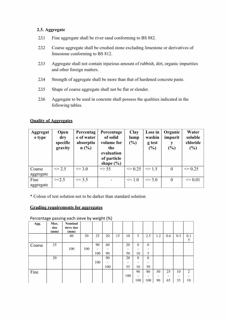
2.3. Aggregate
2.3.1 Fine aggregate shall be river sand conforming to BS 882.
2.3.2 Coarse aggregate shall be crushed stone excluding limestone or derivatives of limestone conforming to BS 812.
2.3.3 Aggregate shall not contain injurious amount of rubbish, dirt, organic impurities and other foreign matters.
2.3.4 Strength of aggregate shall be more than that of hardened concrete paste.
2.3.5 Shape of coarse aggregate shall not be flat or slender.
2.3.6 Aggregate to be used in concrete shall possess the qualities indicated in the following tables.
Quality of Aggregates
Aggregat e type
Open dry
specific gravity
Percentag e of water absorptio
n (%)
Percentage of solid
volume for the
evaluation of particle shape (%)
Clay lump (%)
Loss in washin g test (%)
Organic impurit
y (%)
Water soluble chloride
(%)
Coarse aggregate
<= 2.5 <= 3.0 => 55 <= 0.25 <= 1.5 0 <= 0.25
Fine aggregate
>=2.5 <= 3.5 - <= 1.0 <= 3.0 0 <= 0.01
* Colour of test solution not to be darker than standard solution
Grading requirements for aggregates
Percentage passing each sieve by weight (%)
Agg. Max. size
(mm)
Nominal sieve size
(mm)
40 30 25 20 15 10 5 2.5 1.2 0.6 0.3 0.1 5
Coarse 25 100
100
90 -
60 -
20 -
0 -
0 -
100 90 50 10 5 20 90 20 0 0
100 - - - - 100 55 10 50
Fine 100
90 -
80 -
50 -
25 -
10 -
2 -
100 100 90 65 35 10

2.3.7 Manufactured sand and blast furnace slag to be use in concrete shall not be used unless otherwise specified or approved by the Consultant.
2.3.8 In case of using fine aggregate of 0.01% or more water soluble chloride content, the necessary measures for corrosion inhibiting of reinforcement shall be instructed by the Consultant.
2.3.9 The maximum size of coarse aggregate shall be 25 mm.
2.3.10 Sources of aggregate shall be to the approval of the Consultant and samples of aggregate from the proposed source shall be submitted to the Consultant at least 28 days before its intended use.
2.4. Water
2.4.1 Water shall not contain injurious amount of impurities that may adversely affect concrete and reinforcement.
2.4.2 Ground water shall not be used for concrete works.
2.4.3 Water shall be obtained from a public supply where possible, and shall be taken from any other sources only if approved by the Consultant.
2.4.4 Only water of approved quality shall be used for washing out formwork, curing concrete and similar surfaces.
2.5. Handling and Storage of Material
2.5.1 Cement
2.5.1.1 Cement shall be stored in a manner to prevent weathering.
2.5.1.2 Bagged cement shall be piled no more than 10 bags so as to permit easy inspection
2.5.2 Cement caked even to the slightest extent shall not be used. Such cement and rejected cement shall be immediately separated from other bags of cement so that they shall not be mistaken for others.
2.5.3 Aggregate
2.5.3.1 Aggregate shall be stored in a manner effectively separating coarse and fine aggregate according to type and shall be prevented from inclusion of dirt, rubbish and other undesirable foreign matters.
2.5.3.2 Coarse aggregate shall be unloaded and piled in a manner not to cause segregation of small and large particles. Aggregate to be stored in piles shall be in mounds of moderate height and at a location where good drainage is provided.

2.6. Mix Proportion and Strength
2.6.1 Mix ratio for reinforced concrete shall be in the proportion 1:2:3 (cement: fine aggregate: coarse aggregate) by dry volume.
2.6.2 Mix ratio for lean concrete shall be in the proportion 1:2:6 (cement: fine aggregate: coarse aggregate) by dry volume.
2.6.3 Water-cement ratio for concrete shall be 0.4% to 0.45%
2.6.4 The specified design strength of reinforced concrete shall be 25 N/mm²
2.6.5 The required slump of concrete shall be 100 mm.
2.6.6 Design mix proportion shall be to obtain required workability, consistency and durability.
2.7. Production of Concrete
2.7.1 Field-mixed Concrete Plant
2.7.1.1 The Contractor shall select the necessary facilities for storage, batching, mixing and transporting of each of the materials and submit them for approval of the Consultant prior to start work.
2.7.2 Measuring
2.7.2.1 All materials shall be measure by volume for each batch and water may be measured volumetrically.
2.7.2.2 Cement shall be measured by number of bags unless automatic cement weight measure is in use.
2.7.3 Mixing Control
2.7.3.1 Concrete mixture shall be constantly controlled to obtain required workability and mixed strength. Mixing time for each batch shall be not more than 3 minutes.
2.7.4 Quality Control
2.7.4.1 The Contractor shall conduct tests for quality control toward insuring that concrete of the required quality is constantly produced.
2.7.4.2 The Contractor shall have all quality control tests report ready for submission as required by the Consultant.
2.7.5 Quality Inspection of Concrete at the Point of Placement
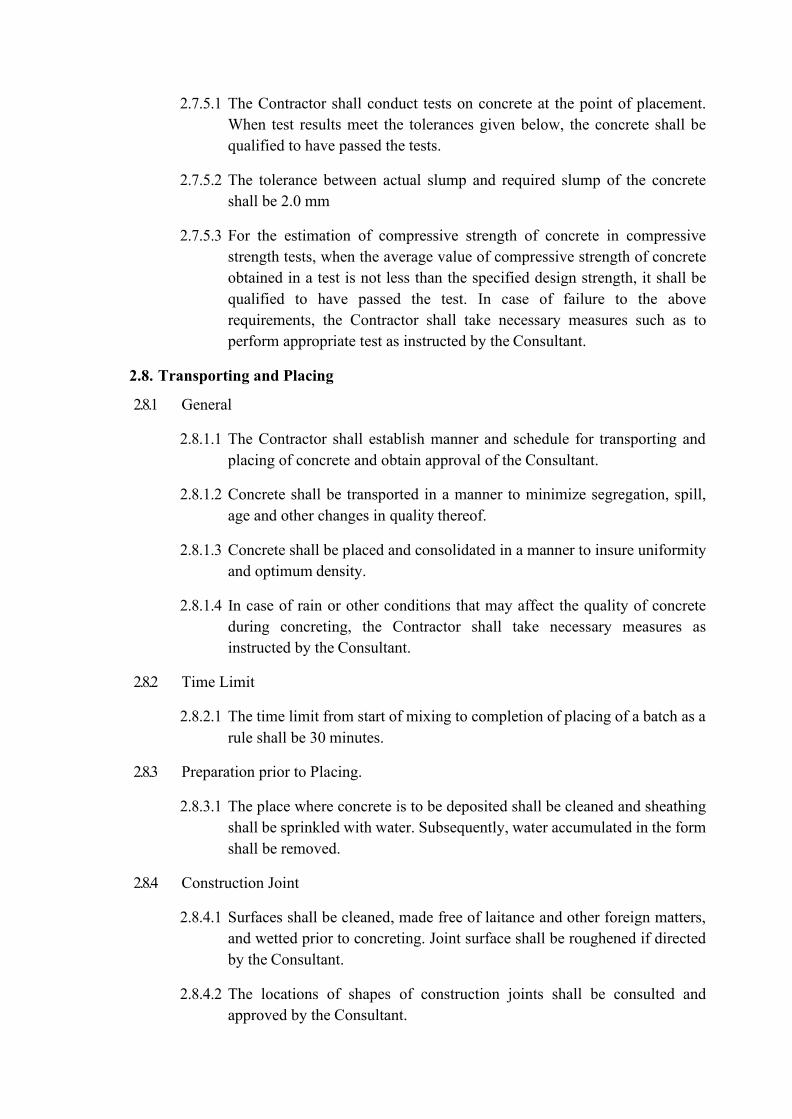
2.7.5.1 The Contractor shall conduct tests on concrete at the point of placement. When test results meet the tolerances given below, the concrete shall be qualified to have passed the tests.
2.7.5.2 The tolerance between actual slump and required slump of the concrete shall be 2.0 mm
2.7.5.3 For the estimation of compressive strength of concrete in compressive strength tests, when the average value of compressive strength of concrete obtained in a test is not less than the specified design strength, it shall be qualified to have passed the test. In case of failure to the above requirements, the Contractor shall take necessary measures such as to perform appropriate test as instructed by the Consultant.
2.8. Transporting and Placing
2.8.1 General
2.8.1.1 The Contractor shall establish manner and schedule for transporting and placing of concrete and obtain approval of the Consultant.
2.8.1.2 Concrete shall be transported in a manner to minimize segregation, spill, age and other changes in quality thereof.
2.8.1.3 Concrete shall be placed and consolidated in a manner to insure uniformity and optimum density.
2.8.1.4 In case of rain or other conditions that may affect the quality of concrete during concreting, the Contractor shall take necessary measures as instructed by the Consultant.
2.8.2 Time Limit
2.8.2.1 The time limit from start of mixing to completion of placing of a batch as a rule shall be 30 minutes.
2.8.3 Preparation prior to Placing.
2.8.3.1 The place where concrete is to be deposited shall be cleaned and sheathing shall be sprinkled with water. Subsequently, water accumulated in the form shall be removed.
2.8.4 Construction Joint
2.8.4.1 Surfaces shall be cleaned, made free of laitance and other foreign matters, and wetted prior to concreting. Joint surface shall be roughened if directed by the Consultant.
2.8.4.2 The locations of shapes of construction joints shall be consulted and approved by the Consultant.

2.8.5 Concrete Placing
2.8.5.1 Concrete placing shall be proceeded to keep the surface of placed concrete as horizontal as possible.
2.8.5.2 Concrete shall be continuously poured to compact around reinforcing bars and corners of formwork.
2.8.5.3 The maximum time interval between placements of continuous concreting shall not exceed 0.5 hours. However, when special measures are taken this time limit may be changed according to instruction or approval of the Consultant.
2.8.6 Consolidation
2.8.6.1 Vibrating of concrete and tapping of formwork shall be performed to wall, column and other places difficult for concrete to proceed. Proper number of workers for placing and compacting concrete shall be arranged.
2.8.6.2 Vibrator shall be operated for concrete called for water tightness, difficult portion for concrete to proceed and other cases directed by the Consultant. However, vibrator shall not be touched reinforcing bars and shall not be operated more than 30 seconds at same spot.
2.8.6.3 Concrete shall be placed 300 - 600 mm thickness at once in case vibrator is performing. In case flexible-insert-vibrator is called for, concrete shall not be placed thicker than the length of the insert or vibrator at one pouring.
2.8.7 Placing Speed
2.8.7.1 Concrete shall be placed at the speed suited for the workability of the concrete and condition of the place of placement, which insures proper consolidation of concrete.
2.9. Concrete Curing
2.9.1 Curing Method
2.9.1.1 After concrete has been placed, the concrete surface shall be kept moist by sprayed with water or by other appropriate methods, and shall be protected from direct sunlight and rapid drying. The top surface of slabs shall be kept flooded with water at all times after concreting for the duration of curing period. This curing period shall be for not less than 14 days.
2.9.1.2 As a rule, no foot traffic or loads shall be permitted on concrete for at least 24 hours after placement.

2.10. Test
2.10.1 General
2.10.1.1 The contractor shall be required to conduct all tests according to BS method and procedure.
2.10.1.2 Test, as a rule, shall be conducted at the locations directed or at the testing institutions approved by the Consultant.
2.10.1.3 The Consultant shall conduct test, as a rule.
2.10.1.4 In case of failure in test, measure shall be taken as instructed by the Consultant.
2.10.1.5 The Contractor shall keep test records during the work and for 2 years after completion of the contracted work.
2.10.2 Material
2.11.1.1 Cement Test
(1) Setting test. (2) Soundness test. (3) Compressive strength test.
Note: Item (1) shall be conducted once in every manufacturer.
Item (2) & (3) shall be conducted once in every 2,000 bags.
2.11.1.2 Aggregate test:
(1) Grading and fineness modules.
2.11. Concrete
2.11.2 Fresh concrete
Slump, air content, shall be conducted daily, and more often at request of the Consultant.
2.11.3 Compressive strength test of concrete
Test for estimation on strength of concrete in structure:
2.11.3.1 In order to assume estimated strength of concrete in structure, compressive strength test shall be conducted for prepared test pieces on the 7th day and 28th day and those test pieces shall be made for sampling at placing of concreting.

2.11.3.2 Strength test shall be conducted for each of the following conditions: each days pour, each class of concrete, each change of supplies or source and each 100 cubic meter of concrete or fraction thereof. The number of test pieces to be used in a test shall be not less than 3 for each test of the 7th day and the 28th day unless otherwise instructed by the Consultant.
2.11.3.3 Test pieces shall be made in accordance with British Standards, and sampling shall be taken as near as possible at the point of placement.
2.11.3.4 Test pieces shall be stored without being disturbed and shall be covered during the first 24 hours, and carefully transported specimens to the testing laboratory. Test pieces shall be cured in water after de- moulding. The temperature of test pieces shall be kept as close as possible to the temperature of the concrete in structure until the time of testing.
2.11.3.5 The test results shall be expressed in the average value by calculating the average compressive strength of all test pieces. The average value must be equal to or greater than the specified strength.
2.12. Defective Concrete and Finishes
2.12.1 Honeycombed surfaces shall be made good or on the instruction of the Consultant be cut out by the Contractor and make good at his own expense.
2.12.2 Concealed concrete faces shall left as from the formwork except honeycombed surfaces shall be made good. Faces of concrete to be rendered shall be roughened by approved means to form a key. Faces of concrete that are to have finished other than those specified shall be prepared in an approved manner as instructed by the Consultant
3. CONCRETE FORMWORK
3.1. Structure and Material
3.1.1 Structure
3.1.1.1 Formwork shall be performed to obtain accurate concrete in accordance with the designated drawings.
3.1.1.2 Formwork shall be firmed and secured to bear the force of concreting and tightened to avoid cement paste seeping.
3.1.2 Materials
3.1.2.1 Sheathing for formwork shall be waterproof plywood of not less than 12 mm thick. Joint of sheathing shall be butt joint and firmly assembled. In case of using wood board for sheathing, boards shall be 15 mm thick and

applied planer. Joint shall be tongued and grooved unless otherwise approved by the Consultant.
3.1.2.2 Form liners shall be sound and suitable materials to accurately and safely cast the in-situ concrete structure as shown on the Drawings.
3.1.2.3 Timber form boards for sheathing where used for fair-faced concrete shall be of such new materials as not to cause any defects to the surface of the concrete. Special care shall be taken in fabrication, storage and protection of these boards.
3.1.3 Other Material
3.1.3.1 Fastening hardware to be used shall be those with allowable tensile strength guaranteed by manufacturer through strength tests.
3.1.3.2 Form oil shall not have injurious effects on quality of concrete nor to bonding of surface finishing materials and shall be subject to approval of the Consultant.
3.2. Performance
3.2.1 Design of formwork
3.2.1.1 Formwork shall be designed to withstand construction leads during concreting, lateral pressure of fresh concrete, shock and vibrators due to concrete placing.
3.2.1.2 Formwork shall be free of injurious leakage of water, easy to remove, and shall not damage concrete at removal.
3.2.1.3 Supports shall be provided with the adequate horizontal and diagonal bracing and/or stays to prevent collapsing, heaving and twisting of formwork due to horizontal loads working during concrete placing.
3.2.2 Tolerance
The dimensional tolerances in location and cross section of concrete member used for designing and construction of formwork shall conform to the following table.
Standard Values of Dimensional tolerances
Item Tolerance (mm) Tolerance in distance from datum line of each floor to respective members
+ 10
Tolerance in cross section of columns, beams and walls
- 5 , + 10
Tolerance in thickness of floor and roof slabs 0, +10

3.2.3 Fabrication and Erection
3.2.3.1 Erection of formwork, and transportation and storage of materials thereof shall be started only after previously placed concrete has reached an age which acceptance of these loads will not have any adverse effect on the concrete.
3.2.3.2 Sheathing shall be fabricated and installed accurately to match the locations, shapes and dimensions of members called for in the Drawings.
3.2.3.3 Sheathing shall be installed tightly so as not to permit cement paste or mortar to escape from joints.
3.2.3.4 Pipes, boxes and other embedded hardware shall be properly secured to sheathing or others so that they will not move during concrete placing.
3.2.3.5 Supports shall be erected plumb. Supports at any two vertically consecutive floors shall be erected as near as possible to identical locations on a common plane.
3.2.3.6 Shoring shall be erected paying special attention to safety.
3.2.3.7 If sheathing is reused, the surface in contact with the concrete shall be thoroughly cleaned off and sufficiently repaired before reuse. In case of using for fair-faced concrete, the same sheathings shall be used twice after approval of the Consultant.
3.2.4 Inspection
3.2.4.1 Formwork shall be inspected by the Consultant prior to placing of concrete.
3.2.5 Striking of forms
3.2.5.1 The minimum period for keeping the forms in position and for watering after laying the concrete shall be as stated below, except otherwise specified in drawings. Forms shall be removed in such a manner as to ensure the complete safety of the structure, so that there is no shock or vibration as would damage the reinforced concrete.
3.2.5.2 The responsibility for the safety of the concrete shall rest entirely with the Contractor and the Contractor shall be held liable for any damage done and shall have to make good the same at his own expenses.
3.2.5.3 The Contractor shall inform the Consultant when he intends to remove shuttering and shall obtain his consent, but the consent of the Consultant shall not relieve the Contractor of his responsibility.

3.2.5.4 The minimum time for formwork to remain in place shall be as per the following table.
Vertical sides of beams, slabs and columns 24 hours Soffits of slab 10 days Soffits of beams 21 days Cantilevers 28 days
3.2.6 Relocation of Support
3.2.6.1 Supports under concrete shall be not relocated
3.2.7 Removal of formwork
3.2.7.1 Formwork shall be removed gently, after its removal has been approved by the Consultant.
3.2.7.2 Inspection by the Consultant shall be obtained immediately after the removal of sheathing and defects shall be immediately remedied according to instruction of the Consultant.
3.2.7.3 After shoring has been removed, members shall be carefully observed for cracking and deflection, when found, they shall be reported immediately to the Consultant.
4. STEEL REINFORCEMENT
4.1. Material
4.1.1 Reinforcing steel shall be of the dimensions given in the Drawings.
4.1.2 Reinforcing bars shall comply with the requirement of B.S.4449 and welded wire fabric, square bar fabric and expanded metal shall comply with appropriate part of B.S.4483.
4.1.3 Diameter 6mm reinforcing steel shall be round mild steel bars, and 12mm, 16mm, 20mm and 25mm shall be deformed high strength bars.
4.1.4 Any other non-specified reinforcing steel shall be used only with the approval of the Consultant.
4.1.5 All reinforcing steel and binding wire shall be stored under cover and shall be at least 250mm above the ground.
4.2. Cleaning
4.2.1 Bars shall be cleaned before use so that it is free from rust, oil, dirt or other coatings that reduce bond.
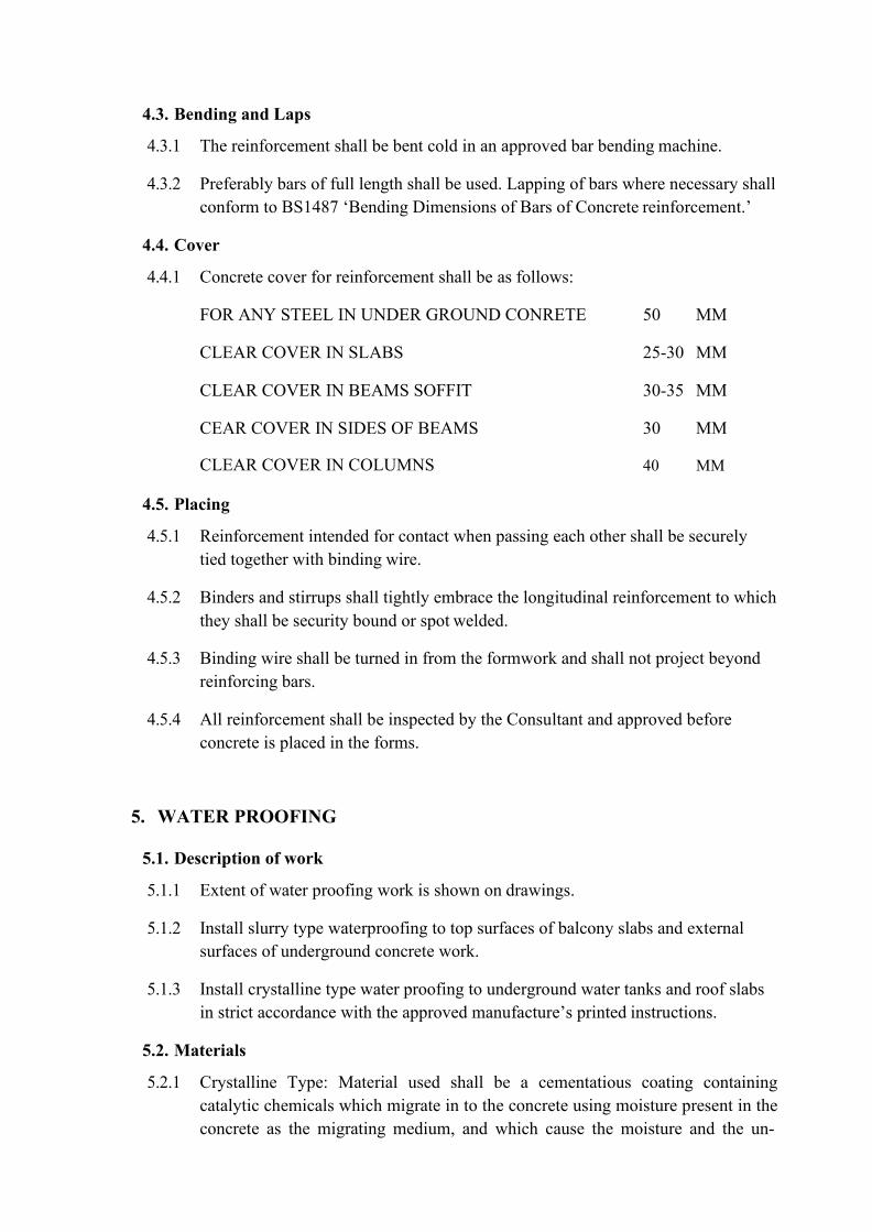
4.3. Bending and Laps
4.3.1 The reinforcement shall be bent cold in an approved bar bending machine.
4.3.2 Preferably bars of full length shall be used. Lapping of bars where necessary shall conform to BS1487 ‘Bending Dimensions of Bars of Concrete reinforcement.’
4.4. Cover
4.4.1 Concrete cover for reinforcement shall be as follows:
FOR ANY STEEL IN UNDER GROUND CONRETE 50 MM
CLEAR COVER IN SLABS 25-30 MM
CLEAR COVER IN BEAMS SOFFIT 30-35 MM
CEAR COVER IN SIDES OF BEAMS 30 MM
CLEAR COVER IN COLUMNS 40 MM
4.5. Placing
4.5.1 Reinforcement intended for contact when passing each other shall be securely tied together with binding wire.
4.5.2 Binders and stirrups shall tightly embrace the longitudinal reinforcement to which they shall be security bound or spot welded.
4.5.3 Binding wire shall be turned in from the formwork and shall not project beyond reinforcing bars.
4.5.4 All reinforcement shall be inspected by the Consultant and approved before concrete is placed in the forms.
5. WATER PROOFING
5.1. Description of work
5.1.1 Extent of water proofing work is shown on drawings.
5.1.2 Install slurry type waterproofing to top surfaces of balcony slabs and external surfaces of underground concrete work.
5.1.3 Install crystalline type water proofing to underground water tanks and roof slabs in strict accordance with the approved manufacture’s printed instructions.
5.2. Materials
5.2.1 Crystalline Type: Material used shall be a cementatious coating containing catalytic chemicals which migrate in to the concrete using moisture present in the concrete as the migrating medium, and which cause the moisture and the un-

hydrated cement in the concrete to react causing the growth of non-soluble crystals of dendritic fibers in the void and capillary tracks of the concrete that allow passage of water, there by rendering the concrete itself water proof.
5.2.2 Acceptable products: Xypex concentrate, modified, ultra plug and quick set as manufactured Xypex chemicals (Canada) Limited (or equivalent).
5.3. Storage of materials
5.3.1 General: All materials shall be stored in original undamaged containers with manufactures seals and labels intact. Material shall be stored off the ground in a dry enclosed area.
5.4. Surface preparation
5.4.1 General: All surfaces shall be examined for form tie holes and defects such as honeycombing, rock pockets, cracks, etc. These areas shall be repaired in accordance with these specifications and the manufactures printed instructions.
5.4.2 Concrete finish: concrete surfaces shall have an open capillary system to provide tooth and suctions shall be clean; free from scale, excess form oil, laitance, curing compounds and other foreign matter.
5.4.3 Smooth surfaces or surfaces covered with excess form oil or other contaminants shall be washed lightly sandblasted, water blasted, or acid -etched with muriatic acid, as required to provide a clean absorbent surfaces.
5.4.4 Horizontal surfaces shall not be troweled or power - troweled, and shall be left with a rough float finish or a broom finish. Vertical surfaces may have a sacked finish. Comply with manufactures specifications for requirements pertaining to minimum ‘age’ of concrete deck surface scheduled to receive water proofing.
5.4.5 Surface moisture: Water proofing shall be applied to ‘green’ concrete as soon as possible after forms have been stripped or to older pours which have been thoroughly moistened with clean water prior to application. Free water shall be removed prior to application.
5.4.6 Mixing of crystalline water proofing compound: comply with manufactures specification for 2-coat installation.
5.5. Application
5.5.1 General: Apply all materials under the direction of the manufacturer’s representative.
5.5.2 Constructions joints and surface defects: Comply with waterproofing material manufacturer’s printed directions in the preparation, and treatment of construction joints and surface defects.

5.5.3 Surface application: After all repair, patching and sealing strip placement has been prepared in accordance with manufacturer’s recommendations and approved by manufacturer’s representative, treat concrete surface with first coat slurry mix of crystalline waterproofing compound.
5.5.4 Brushing: Use a short bristle or broom to work the slurry well into the concrete, filing all hairline cracks and surface pores.
5.5.5 Second coat: Apply second coat while first coat is still ‘green’ but after it has reached an initial set, all as recommended by the water proofing material manufacturer.
5.6. Curing
5.6.1 General: Curing shall begin as soon as the waterproofing materials have set up sufficiently so as not to be damaged by a fine spray. Treated surface shall be sprayed three times a day for a three-day period. Allow material to set 12 days before filling the structure with liquid
5.6.2 Protect treated surfaces from damage due to wind, sun, rain and temperatures below 35 degrees F. For a period of 48 hours after application, arrange protections to permit proper curing conditions for waterproofing material.
5.6.3 Clean up: Remove all surplus materials from the premises and leave all areas
broom-clean. In the case of temporary protections remove all such items carefully to avoid damage to treated surfaces. Assemble all such materials and remove from premises followed by broom cleaning as noted.
6. EMBEDDED DAMPPROOF MEMBRANE
6.1. General
6.1.1 This section deals with laying of flexible sheet as damp proof membranes or has chemical or vapour barriers embedded in the fabric of the building. It does not deal with the weather-proof roof sheeting, or with vapour barriers.
6.2. Products
6.2.1 Polythene sheets for under slab DPM: gauge 500, manufacturer and reference to approval.
6.2.2 Adhesive tape: A type recommended by the sheet manufacturer.
6.3. Workmanship
6.3.1 Manufacturers Recommendations: to be strictly followed for all products and materials. Apply sheets to clean, dry surfaces with all joints sealed to give a completely water proof continues membrane.

6.3.2 Polythene Sheet Under-Slab Dpm: lay a level bed of fine sand, not less than 13mm thick or as specified to receive membrane.
6.3.3 Polythene Sheet Dpm: ensure that sheets are clean and dry. Lay single layer loose on base, lap edges 150mm and seal with mastic or adhesive tape.
6.3.4 Pipe Etc: where pipe etc. pass through sheeting make junction completely watertight by forming collars fully bonded / sealed to both pipes and sheeting.
6.3.5 Project: finished sheeting adequately and prevent puncturing during following work sheet to be covered by permanent over laying construction as soon as possible.
7. STRUCTURAL STEEL
7.1. Scope
7.1.1 This section shall apply to the work involved with structural steels. All incidental items of structural steel shall be stated in the particular specification.
7.2. Materials
7.2.1 Steel
7.2.1.1 Shape of steel shall be precise and straight and free of injurious scratches and rust.
7.2.1.2 All steel sections shall be galvanized sections of strength class 43 A.
7.2.1.3 Dimensions of steel section and tolerance of dimension shall conform to standard dimension of steel regulated in ASTM or BS standard.
7.2.2 Bolt
7.2.2.1 Shape of bolt, nut, and washer shall be in accordance with requirement of BS 4190 & BS 3692.
7.2.2.2 Quality of bolt shall be SC 43 A.
7.2.3 Welding Rod
7.2.3.1 Arc welding rod shall conform to materials to be welded, and position.
7.3. Fabrication
7.3.1 Main fabrication shall be done in workshop unless otherwise specified or approved by the Consultant.
7.3.2 Full scale drawing of each section shall be drawn prior to fabrication and checked by the Consultant.

7.3.3 Section of each material shall be cut perpendicular to axis unless otherwise specified in the drawing.
7.3.4 Saw and angle cutter shall be used for cutting, and cut section shall be free of any noticeable defect.
7.3.5 Deformation caused by cutting shall be corrected.
7.3.6 Normal temperature or hot drawn process shall do bending process. Steel shall be red heat in hot drawn process.
7.3.7 Those directed in the drawing shall be chiselled finish and completely attached. Materials shall be checked for bend, distortion, warp, etc. before fabrication.
7.4. Bolt
7.4.1 Hole
7.4.1.1 Spacing of bolt holes shall be as directed in the following table.
Diameter of Bolt
Standard Pitch Minimum Pitch
End Distance
Edge Distance
12 50 30 30 25 16 50 40 40 30
7.4.1.2 Minimum pitch and end distance for lightweight steel shape shall be more
than 3 times and 2.5 times a Bolt diameter respectively.
7.4.1.3 Diameter of hole shall not be over 0.5 mm larger than bolt diameter. However, for anchor bolt 5mm clearance shall be allowed between bolt diameter and diameter of hole unless otherwise specified.
7.4.1.4 Bolt hole shall either be drilled open or reamed after sub punching. Punching can only be permitted for a material thickness less than 13 mm.
7.4.1.5 Rolled edge around a hole shall be removed.
7.4.1.6 Position of a bolt hole shall be precise so that the centre of all holes aligns.
7.4.2 Protection against loosing of Nuts
7.4.2.1 Nuts shall be protected against loosing by concrete covering, double nuts or other proper means.
7.5. Welding
7.5.1 Welding
7.5.1.1 Welder shall have an authorized qualification in Maldives and approved by the Consultant.

7.5.1.2 Other tests shall be conducted to confirm welder’s skill in accordance with type of work.
7.5.1.3 Tack welding shall be carried out by the welder approved by the Consultant.
7.5.2 Welding Machine
7.5.2.1 Arc welding machine shall be alternate or direct current type, which provides sufficient and adequate current.
7.5.3 Preparation
7.5.3.1 Welding shall be done as much downward as possible using a jig such as Rotary frame.
7.5.3.2 Welding rod shall be always kept in a dry area and if necessary, dried by drying equipment.
7.5.3.3 Welding surface shall be free of water, scale or others injurious to welding work. Slag appeared on the created surface in the middle of welding shall be cleaned before starting again.
7.5.4 Fabrication
7.5.4.1 Welding edge shall be smoothed by automatic gas cutting or other proper finishes.
7.5.5 Finishes
7.5.5.1 Surface of welds shall be as smooth as possible and size and length of welds shall not be less than designed dimensions.
7.5.5.2 Reinforcement of weld shall not exceed 0.1s + 1 mm (s: Designated size) in fillet welds.
7.5.5.3 Welded parts shall be free of undercut, overlap, crack, blow hole, lack of welds, and lack of weld settlement, rolled up slag or other defects.
7.5.5.4 Crater at the end of bead shall be carefully heaped up and slag, sputter, etc. shall be completely removed after welds.
7.5.6 Safety
7.5.6.1 Safe scaffoldings shall be provided for the field welds work.
7.5.6.2 Welding facilities shall be such that there shall be no electric leakage of electric shock. There also shall be sufficient protection for fire.
7.5.6.3 Electric shock protection device shall be used and also care shall be taken not to get suffocated or intoxicated by gas when welding in small area.

7.5.7 Inspection
7.5.7.1 Welding parts shall be inspected before, during and after welding in accordance with work schedule.
7.6. Erection and Field Painting
7.6.1 Erection
7.6.1.1 Erection procedure shall be prepared by the contractor and be approved by the Consultant prior to the erection.
7.6.1.2 Material shall be stored on flat surface in order not to get distortion, twist or other defects. Correction shall be made to those distortions or twisted before erection.
7.6.1.3 Horizontal reinforcement and bracing shall be placed and bolts are temporary tightened as trusses are put up.
7.6.1.4 Connection of materials by bolts, etc. shall be made after distortion on plumb is thoroughly corrected.
7.6.1.5 Temporary bracing or other reinforcement shall be placed to resist wind pressure or other loads erection.
7.6.1.6 When heavy objects are placed on a horizontal element in the course of erection, they shall be reinforced with prior approval of the Consultant.
7.6.1.7 Care shall be taken on all facilities so that there is no accident.
7.6.2 Field Painting
7.6.2.1 All steel work shall delivered to site unprimed shall be cleaned of impurities, scrapped and wire brushed to remove rust and painted with one coat of priming paint applied by brush.
7.6.2.2 Steelwork delivered to Site primed shall be cleaned of impurities and damage to the priming paint and made good with priming paint.
7.6.2.3 Galvanized steelwork to be painted shall be cleaned of impurities. Where rusting has occurred the rust shall be removed by wire brushing and made good with an approved rust inhibitor. The surfaces shall be coated with a mordant solution, washed with clean water and painted with two coats of priming paint applied by brush.
7.6.2.4 Steelwork, which is to be concealed shall be prepared and primed as above and shall be painted with two priming coats and one finishing coat of paint applied by brush.
7.6.3 Anchor Bolt
7.6.4 The other methods for movable burying shall be as directed by the Consultant.
8. MASONRY
8.1. Materials
8.1.1 Material used for masonry and plastering work shall conform to Section 3 - CONCRETE WORKS.
8.1.2 Masonry work shall be done with cement bricks or blocks of approved quality unless specified otherwise.
8.1.3 The blocks shall be free from excessive amounts of salt or other impurities and shall be inspected and approved by the Consultant.
8.2. General
8.2.1 Execution Drawing
8.2.1.1 Work shall be complied with this specification unless otherwise stated on particular Specification or Drawings. Any work not specified shall be discussed and directed by the Consultant. Execution drawing of block or brick alignment (inclusive of indication for hanging bolt, wood plug and conduit pipe), detail reinforcement, window opening, and other requirement shall be prepared and submitted for the Consultant.
8.2.2 Stake-Board
8.2.2.1 Stake-board shall be provided at each 5m in length and shall be inspected by the Consultant for the accuracy, firmness and secureness. However, suitable ruler, plumb bob and leveller shall be provided for minor performance of cement block and bricks.
8.2.3 Transportation and storing
8.2.3.1 Care shall be taken for damage during transportation of materials and any defect of natural finished concrete blocks or bricks shall be rejected.
8.2.3.2 Different size of material shall be stored separately and projected from dirt and other impurities.
8.2.4 Curing
8.2.4.1 Any shock or load shall not be applied until concrete mortar or other fills hardened. Corner, projection and top of cement block or brick work shall be protected from rain, dryness, cold, damage and stain by covering.
8.2.4.2 Void between blocks or bricks shall not be intruded by rainwater.

8.3. Blockwork
8.3.1 Material
8.3.1.1 Blocks shall be of standard quality low permeability blocks with no defects and sample shall be submitted for approval of the Consultant.
8.3.1.2 Blocks shall be Solid cement blocks 125 mm thick for external walls and hollow cement blocks 100 mm thick for internal walls. The average compression strength should be not less than 2.8N/mm2 and shall comply with physical requirements of ISO 6073: 1981
8.3.2 Horizontal reinforcement for concrete block wall;
8.3.2.1 Horizontal reinforcement shall be provided at end of wall adjoining to concrete column. Reinforcing bar shall be anchored into end block and column.
8.3.2.2 Horizontal reinforcing bar for block wall shall be 6 dia. @ 1000 mm.
8.3.3 Placing Blocks & Bricks
8.3.3.1 Cement blocks shall be saturated with water and joint shall be cleaned.
8.3.3.2 Bonding mortar shall be used immediately after mix, and mixed mortar left for more than one hour shall be rejected.
8.3.3.3 Vertical and horizontal joint of blocks shall be filled completely and suitable with mortar on line shall not be moved or rearranged. Joint and surface of block of exposed finished block wall shall be cleaned immediately after joint is filled.
8.3.3.4 In case concrete block wall is attached to structural concrete, block wall shall be placed before concreting structure.
8.3.3.5 Mortar for joint shall be touched with steel trowel before hardened and exposed joint shall be finished with uniform width and planned without roughness or cavity.
8.3.3.6 Height for placing block per day shall be maximum 1.2 m unless otherwise specified.
8.3.3.7 Blocks shall be placed with cavity side under.
8.3.4 Joints
8.3.4.1 The thickness of joints shall not exceed 10 mm and the joints shall be rated (13 mm dup.) when the mortar is still floor, so as to provide for proper bond for the plaster. Any mortar which falls on the floor from these joints or removed due to raking of joints shall not be reused.

8.3.5 Lintel
8.3.5.1 Lintel shall be reinforced concrete as approved or directed by the Consultant.
8.3.5.2 Main reinforcing bar shall be anchored more than 40D (40 x diameter of the bar) at both end.
8.3.5.3 In case lintel is prefabricated, shop drawing shall be submitted for approval of the Consultant.
8.3.6 Frame of Opening
8.3.6.1 In case frame is temporarily installed before placing of blocks, frame shall be firmly placed and joiner shall be bonded with mortar as placing each block at side and top of frame.
8.3.6.2 In case frame is installed after placing of blocks, joiner shall be bonded with additional mortar at space or every two blocks or more.
8.3.6.3 Back of frame shall be filled and compacted with mortar by providing shuttering board.
8.3.6.4 Wood plug and anchor bolt shall be covered with mortar or concrete.
8.3.7 Piping
8.3.7.1 Principally, piping shall not be placed in block wall unless piping block is in use.
8.3.7.2 In case electric conduit pipe is placed in cavity of concrete blocks, care shall be taken not to obstruct reinforcing bar, and cavity shall be completely filled.
8.3.7.3 In case chipping and piping on face of blocks is unavoidable, performance shall confirm to instruction of the Consultant.
8.3.7.4 Joiner and supporter for exposed piping shall be buried at joint which back is filled or otherwise approved by the Consultant.

9. PLASTERING
9.1. General
9.1.1 All masonry walls shall have smooth finished cement plaster on both sides with a surface setting coat of neat cement applied within an hour of the completion of rendering.
9.1.2 Cement rendering to floor shall be same as above.
9.2. Materials and Storage
9.2.1 Plaster materials which are affected by moisture such as plaster and cement shall be stored properly.
9.2.2 Materials used for plastering shall conform to those of Section 3 - Concrete Works. Grading of sand, however, shall be as in table below
Grading of sand Mortar plastering Plastering
5mm sifting thorough 100% 0.15mm sifting less than 10%
for first coat for finish coat
for first coat and dubbing out
2.5mm sifting through 100% 0.15mm sifting less than 10%
for finish coat for second coat
9.2.3 White cement or filler or similar shall confirm to the requirements of Portland
cement, BS.12.
9.2.4 The use of mixtures shall be approved by the Consultant’s representative. The amount of admixture shall be such that it affects mortar strength very little.
9.3. Mixing ratio
9.3.1 Mixing volume ratio of mortar shall be as in table below:
Base area of application
first coat cement:sand
Dabbing out cement:sand
Finish coat cement:sand
Masonry blocks
Floor Interior wall Exterior wall
- 1:4 1:4
- 1:4 1:4
1:4 1:4 1:4
9.4. Thickness of Coating
Standard thickness of coating (mm) Base Area of
application First coat
Dubbing out
Second coat
Finish coat Total
Masonry block
Floor Interior wall Exterior wall
- 8 8
- - -
- 8 8
as per dwg 4 4
as per dwg 15 15
Thickness of coating shall be standard thickness of coating unless otherwise indicated on the Drawings.

9.5. Finish
9.5.1 Type of finish and work schedule
Type Work Schedule Notes 1.Smooth Trowel finish
1. Shall be applied flat by metal trowel 2. Shall be finished by pressing with the trowel.
Before applying second coat, corner and edge shall be screed well.
2. Wooden float finish
Shall be applied by wooden float
9.6. General Preparation
9.6.1 Remove efflorescence, laitance, dirt and other loose material by thoroughly dry brushing.
9.6.2 Remove all traces of paint, grease, dirt and other materials incompatible with coating by scrubbing with water containing detergent and washing off with plenty applying coatings unless specified otherwise.
9.6.3 In-situ Concrete Surfaces: Scrub with water containing detergents to ensure complete removal of mould oil, surface retarders and other materials in compatible with coating. Rinse with clean water and allow to dry unless specified otherwise.
9.6.4 Organic Growths: Treat with fungicide to manufacturer’s recommendations and bush off.
9.6.5 Hacking for Key: roughen specified surfaces thoroughly and evenly by removing the entire surface to a depth of 3mm by scrabbling, bush hammering or abrasive blasting, clean surfaces by washing and brushing.
9.6.6 Smooth Concrete Surfaces: where no keying or mix or bonding agent is specified, wet smooth concrete surfaces immediately before plastering.
9.7. External Plastering
9.7.1 Dissimilar Solid Backgrounds for Plastering: where plaster is to be continued without break across joints between dissimilar solid backgrounds which are rigidly bonded together, cover the joints with a 200mm wide mesh strip (back grounds in the same plane) or with the corner mesh (internal angle) fixed at not more than 600mm centres along both edges , unless specified or otherwise.
9.7.2 Dissimilar Solid Backgrounds for Plaster: where plaster is to be continued without break and without change of plane across the face of a 300mm and rigidly bonded to the background.

9.7.2.1 Cover the face of the column /beam/ lintel with building paper extending 25 mm on the adjacent background.
9.7.2.2 Over lay with expanded metal lathing extending 50mm beyond the edges of the paper and securely fixed with masonry nails at not less than 100mm centres along both edges.
Alternatively, an approved paper and mesh lathing may be used. 9.7.2.3 Dissimilar Solid Backgrounds for Rendering: where rendering is to be
continued without break across joints between dissimilar solid backgrounds which are in the same plan and rigidly bounded together, cover joints with a 150mm wide strip of building paper overlaid with 300mm wide metal lathing fixed at not more than 600mm centers along both edges unless specified otherwise.
9.7.2.4 Service Chases: cover with steel mesh strip fixed at not more than 600mm centers along both edges.
9.7.2.5 Conduits bedded in under coat to be covered with 90mm wide jute scrim budded in finishing coat mix, pressed flat and trowelled in. Do not lap ends of scrim.
9.8. Internal Plastering
9.8.1 Accuracy of plaster 15mm thick or more: maximum permissible gap between an 1800mm straight edge and any point on the surface to be 3mm.
9.8.2 Dubbing Out: if necessary to correct inaccuracies, dub out in thickness of not more than 10mm in same mix as first coat. Allow each coat to set before the first is applied. Cross scratch surface of each dubbing out coat immediately after set.
9.8.3 Metal Mesh Lathing: Work undercoat well in to interstices to obtain maximum key.
9.8.4 Under Coats: generally to be not less than 8mm with thickness greater than 16mm applied as two equal coats. Rule to an even surface and cross scratch - end coat to provide a key for the next hand applied coat.
9.8.5 Cement Based Under Coats: all to dry out thoroughly but not rapidly, to ensure that drying shrinkage is substantially complete before applying next coat.
9.8.6 Dissimilar Backgrounds: where scrim or lathing or beads are not specified, cut through plaster with a fine blade in a neat, straight line at junctions of :
9.8.6.1 Plastered rigid sheet and plastered solid backgrounds.
9.8.6.2 Dissimilar solid backgrounds.

9.8.7 Smooth Finish: trowel or float to product a tight matt, smooth surface with no hollows abrupt change of level or trowel marks. Do not use water brush and avoid excessive trowelling and over polishing.
9.9. External Rendering
9.9.1 Dubbing Out: if necessary to correct inaccuracies, dub out in thicknesses of not more than 10mm in same mix as first coat. Allow each coat to dry before the next is applied. Cross scratch surface of each dubbing out coat immediately after set.
9.9.2 Under Coats for hand applied finishes:
9.9.2.1 Apply first undercoat or dubbing out coat by throwing from a trowel.
9.9.2.2 Coats to be no less than 8mm thick, with thickness greater than 16mm applied as two equal coats. On weak backgrounds first under coat to be not less than 10mm thick.
9.9.2.3 Brush down each under coat to remove dust and loose particles and wet thoroughly before application of next coat.
9.9.2.4 Cross scratch under coat without penetrating the coat, to provide key for following coat(s).
9.9.2.5 Drying: Keep each coat damp for the first three days by covering with polythene sheet and/or spraying with water. Thereafter prevent from drying out too rapidly. Work in shade whenever possible.
9.9.3 Allow each coat to dry out thoroughly to ensure that drying shrinkage is substantially complete before applying next coat.
9.9.4 Playing Floated Finish: Finish with wood or other suitably faced float to give an even texture.
9.9.5 Do not draw excessive laitance to surfaces.
9.10. Metal Mesh Lathing / Reinforcement For Plastered/Coatings.
9.10.1 Lathing to be provided as reinforcement for plastering in columns, walls or specified in drawings products.
9.10.2 Products:
9.10.2.1 Plain Expanded Metal Lathing: To B.S 1369 with a minimum weight of 1.9 kg/mm2. Manufacturer to approval of the Consultant.
9.10.2.2 Wire Ties: Unless other specified, annealed iron, galvanized to B.S 443.
9.10.2.3 Clout Nails: galvanized steel or stainless steel nails to B.S 1202: Part 1, table 3.

9.10.2.4 Staples: Galvanized steel wire staples to B.S 1494: Part 2.
9.10.3 Workmanship
9.10.3.1 Framing: fix securely and accurately to help ensure that coatings on lathing , when finished, are true to line and level , within specified tolerances and free from cracks, rippling, hollows, ridges and sudden changes of levels.
9.10.3.2 Runners/Bearers spanning between concrete beams/ribs: fix with 3mm wire ties twisted around 38 mm X 10 gauge screws driven well into fixing blocks or plugs in sides of beams/ribs.
9.10.3.3 Wire Ties: twisted ends tightly together, cut off surplus and bend ends of wire away from face of coating.
9.10.3.4 Plain Expanded Metal Lathing:
(a) Stretch lathing and fix securely in accordance with manufacturers recommendations to give a taut, firm base for plaster/ rendering.
(b) Fix with the long way of the mesh at right angles to supports and with all strands sloping in the same direction.
(b) Lap side edges not less than 25mm. Lap ends 50mm at supports and 75mm between supports. Laps must not occur within 100mm of angles or bends.
10. CARPENTRY AND JOINERY
10.1. Materials
10.1.1 Timber shall be in accordance with the requirements of BS 1186 ‘Quantity of Timber and Workmanship in Joinery’, Part 1, ‘Quality of Timber’.
10.1.2 Timber and timber products shall be subject to the inspection and approval of the Consultant.
10.1.3 Timber shall be seasoned to stable moisture content compatible with the finished use, straight and true and free from wind, warp and distortion and in lengths suitable for the members required.
10.1.4 All timber shall be in long lengths and laps, scars or splices shall be over a bearing surface. Where obtainable, finishing timber exposed to view shall be in single lengths.
10.2. Preservation of Timber
10.2.1 All timber shall be treated for insect attack and is to be of the correct moisture content and free from surface moisture content and dirt.
10.2.2 All rafters, purlins, framing scribe pieces, wall plates, and trusses etc. shall be treated for insect attack with approved timber preservative. No extra payment shall be made for such coating and will be considered inclusive in the rate of the respective item in the BOQ.
10.2.3 Treatment shall be carried out after all cutting and shaping is completed.
10.3. Hardware
10.3.1 Hardware shall be standard quality and samples shall be submitted to the Consultant for approval.
10.3.2 All hinges shall be stainless steel or brass and shall be approved by the Consultant.
10.3.3 The dimensions and quality of hardware shall meet the requirements and shall not be rested, deformed or defective.
10.4. Dimensions and Finish
10.4.1 All dimensions of timber given are finished dimensions.
10.4.2 All elements and others of structural nature, which are exposed, must be machine planed to a smooth finish.
10.4.3 All unexposed timber shall be machine planed to a rough finish.
10.4.4 All joinery work shall be dressed on all four sides and hand dressed where necessary and sanded to all exposed surfaces. All arises in any way accessible shall be sanded and smoothed off.
10.5. Workmanship
10.5.1 All connections whether nailed, screwed glued, mortised or dove-tailed shall be accurately made and properly executed to provide sound, satisfactory connections for the class of work required.
10.5.2 Timbers containing defects or distortions shall not be used.
10.5.3 All joinery shall be manufactured by skilled tradesman with accurate tolerances and set out and with tools, jigs, machines and equipment appropriate for the work.
10.5.4 Assembly of the joinery units and joinery frames, etc. shall be by means of glued connections appropriate to the work - mortise and tennon, housing and doweling, etc. where practicable including the use of glued blocks wherever required. Nailing, screwing shall only be used with prior approval of the Consultant; corrugated fasteners shall not be used for effecting connections.

11. ALUMINIUM DOORS AND WINDOWS
11.1. Aluminium Doors and Windows
11.1.1 All windows and doors are to be constructed by approved specialist suppliers of medium section to the particular requirements noted on the drawings as to weight and profile. All sections shall generally conform to relevant British Standard Specifications.
11.1.2 All frames should be made to fit the actual openings with a 3 mm clearance all around. Discrepancies in overall width or height exceeding 3mm will not be allowed and the frames will be rejected in such cases. Any small discrepancies shall have the gaps suitably backed and filled with gun-applied water repellent mastic sealant
11.1.3 All sealants used in the assembly of, and in the fixing of cladding and window framing, shall be non-setting to allow thermal movement without detriment to those joint sealants used for peripheral caulking and shall be one part silicone sealant and shall conform to BS 4245. All spliced joints between mullions should be sealed with an approved silicone product, compatible with other sealants and packings used.
11.1.4 The auxiliary components in sashes as locks, pivots, sliding gear etc. shall comprise of stainless steel or resisting materials.
11.1.5 The tolerances are to be as follows:
a) Inside width of frame 3mm Maximum b) Inside height of frame 3mm Maximum c) Depth of frame 2mm Maximum d) Opposite side, Inside distance 2mm Maximum
11.1.6 The performance - associated requirements are
1) Strength (resistance to wind pressure and other forces applied in use) 2) Air tightness or ability to cut out drafts. 3) Water - tightness against rain or dew. 4) Sound arresting effect to (shut off noise from outside as well as inside).
11.1.7 All surfaces shall have an anodized protective surface layer of minimum 60 Micron thickness.
11.1.8 Glazing shall be done as specified by the Consultant. Glass shall be tinted, or as specified in the drawings. Thickness shall be according to the size of panels as given hereunder.
Not exceeding 1 sq. ft. 2mm
Exceeding 1 sq. ft. but not exceeding 2 sq. ft. 3mm Exceeding 2 sq. ft. but not exceeding 4 sq. ft. 4mm Exceeding 4 sq. ft. but not exceeding 6 sq. ft. 5mm

Exceeding 6 sq. ft. but not exceeding 12sq. ft. 6mm Exceeding 12sq. ft. > 8mm or as approved by
consultant
11.1.9 Prior to import and / or purchase of the Aluminium Doors and Windows, the relevant specification of the manufacturer, along with samples has to be submitted to the Consultant for approval. This clause shall not be contravened on any account.
11.1.10 The fitting shall be done with utmost care not to spoil the finishes given by the manufactures, and any cleaning done shall be done with cleaners etc. as specified by the Manufactures.
11.1.11 The Contractor shall provide all items, articles, materials, operations, mentioned, or scheduled on the drawings, including all the labour materials, including fixing devices, equipment and incidentals necessary as required for their completion.
11.1.12 The Contractor shall submit shop drawings and/or samples of each type of doors, windows, railings and other items of metal work to the Consultant for approval. The shop drawings shall show full size sections of doors and windows etc. thickness of metal, details of construction hardware as well as connection of windows, doors and other metal work to adjacent work.
11.1.13 Aluminium doors and shutters shall be manufactured by an approved manufacturer and shall be of sections, sizes combination and details shown on the drawings. The frame member shall be one piece, corners shall be electrically welded, ground smooth and true and glazing bare shall be threaded or interlocked as approved by the Consultant.
11.1.14 Glazing for doors and windows shall be of specified thickness and of approved quality and shall conform to specification of glazing. Fixing for glazing shall be done with aluminium Snap-On beading as per detail drawing and instructions. Necessary continuous rubber gaskets of approved make shall be provided.
11.1.15 Colour for doors and windows shall be approved by the Consultant.
11.2. Aluminium louvers
11.2.1 Product data shall be submitted for approval; this shall include specified model and AMCA ratings or equivalent.
11.2.2 Contractor shall submit all shop drawings indicating materials, construction, dimensions, accessories, and installation details.
11.2.3 Contractor shall submit samples of the product for approval.
11.2.4 Louvers shall be warranted against manufacturing defects for a period of 5 years.

11.2.5 Louvers shall comply with AAMA specification 2605 “Voluntary Specification for High Performance Organic Coatings on Architectural extrusions and panels”, ASTM B244 -68, AAC22A41 or equivalent.
11.2.6 Louvers shall be well suited for the design environment (temperature, humidity, and ventilation); i.e., it shall be within manufacturer’s recommended design environment limits for optimum results.
11.2.7 All louvers shall be installed according to manufacturer’s instructions.
11.2.8 All units shall be installed plumb, well fitted and securely attached to supporting frames.
11.2.9 Delivery of materials to site in shall be in manufacturers’ original, unopened containers and packaging with labels clearly indicating manufacturer, material and location of installation.
11.2.10 Materials shall be stored in a dry area indoors and protected from damage in accordance with manufacturer’s specifications.
11.2.11 Materials and finishes shall be protected during handling & installation to prevent damage.
11.3. Top hung windows, ventilators and side hung doors
11.3.1 All windows and doors should be weather stripped. The weather protection should be achieved by a positive compressive action against the section and should not depend on external contact. At every contact between two profiles two weather stripping sections should be provided to complete weather protection.
11.3.2 The bottom section for hinges must be capable of being adjusted vertically if necessary. The gap between section and the floor should be covered with a pair of special splay-tube sections.
11.3.3 The shutter sections for both windows as well as doors shall be hollow section type and shall be overall size 57 x 45 mm and the door sections shall be overall size 81 x 45 mm (including flanges).
11.3.4 The shutters of the windows and doors should be assembled with stainless steel pins and nylon washers. Handles shall be anodised aluminium finished to match the aluminium sections and mounted with self-lubricating nylon washers.
11.3.5 A mortise cylinder rim automatic deadlock of high quality with double pin tumbler shall be used.
11.3.6 Windows shall have anodised aluminium handles, colour as framing and a latching mechanism securing the shutter to the frame both at the top and bottom.
11.3.7 Required fittings;

11.3.7.1 Single action door closer concealed in the head bar of the outer frame and mounted on an adjacent pivot at the threshold and deadlock fitted.
11.3.7.2 The left hand leaf of double doors with flush bolts at head and sill with deadlock fitted to the right hand leaf.
11.3.7.3 Escape doors to have panic bolts assembly with vertical elements concealed in the sill and door closer as in 12.3.7.1.
11.4. Installation
11.4.1 Aluminium work shall be installed adjusted and glazed by experienced workmen all in accordance with the manufacturer's installation instructions and in full conformity with the approved shop drawings, samples and other submitted data. Under no circumstances shall materials be installed on surfaces that contain condensation, dirt, grease or other foreign encountered materials that would hinder or prevent proper installation and functioning for the use intended.
11.4.2 Aluminium work shall be carefully and accurately assembled with proper and approved provision for contraction and expansion and set in correct locations as per approved detailed shop drawings, all level, square, plumb and aligned with other work. All joints between framing and structural building shall be sealed in order to be watertight and weather-proof and to satisfy all other requirements of the Consultant.
11.4.3 Frames shall be designed and manufactured with a maximum 2.5mm tolerance around the opening in the structure. These joints are to be finished by applying an approved sealant into a polystyrene foam backing strip.
11.4.4 All aluminium works are to be fully protected for the duration of the contract from damage by other trades. The Consultant shall approve the method of protection.
11.4.5 If for any reason final finishes become scratched, abraded or damaged during transport, delivery, storage or erection, it shall be the Contractor's responsibility to remove or repair those defective areas or components as directed and to the complete satisfaction of the Consultant.
11.4.6 Repair work shall be identical to the manufacturer's applied finish with regard to gloss, finish and visual appearance. Field touch up of painted aluminium is permitted only with the written permission of the Consultant. Where touch up is not an authorised means of repair the damaged materials must be replaced by new.
11.4.7 Upon completion of work all protective coverings from all exposed surfaces shall be removed. All surfaces shall be cleaned using soap or detergents as recommended by the aluminium manufacturers to remove sealants, discolouration and any other foreign material. Defection of any type determined by the Consultant shall be repaired at the Contractor's expense.

11.4.8 Extreme care shall be taken when cleaning the exterior portion to protect all other adjacent works.
11.5. 12.5 Sealing joints
11.5.1 The Contractor shall ensure that joints are dry and remove all loose material, dust and grease.
11.5.2 Joints shall be prepared in accordance with sealant manufacturer's recommendations using recommended solvents and primers where necessary.
11.5.3 Adjoining surfaces which would be impossible to clean if smeared with sealant shall be masked.
11.5.4 Backing strips shall be inserted in all joints to be pointed with sealant. When using backing strips, the Contractor shall not leave gaps and shall not reduce depth of joint for sealant to less than the minimum recommended by the manufacturer.
11.5.5 Cavities shall be filled and jointed with sealant in accordance with the manufacturer's recommendations. Sealant shall be tooled to form a smooth flat bed.
11.5.6 Excess sealant shall be removed from adjoining surfaces using cleaning materials recommended by the sealant manufacturer, and shall be left clean.
11.6. Glass installation
11.6.1 Workmanship shall generally be in accordance with CP 152 and respective British Standards.
11.6.2 The glass is to be delivered to the site with adequate protection to prevent damage and where possible it is to be fixed in position immediately after delivery. When fixed the Contractor is to take all necessary precautions to prevent damage during succeeding building operations and will be entirely responsible for the replacement of any broken or damaged glass at his own cost.
11.6.3 The Contractor is to be solely responsible for determining the exact sizes of glass required, including a tolerance of 2mm to each edge and he is recommended to check the necessary dimensions on site.
11.6.4 No glazing is to be carried out until rebates have been painted with primer. Glazing beads as applicable are also to be primed before fixing.
11.6.5 All mastic is to be neatly struck off to agree exactly with site lines inside and out.
11.6.6 Rates are to include for all necessary springs, clips, setting blocks, location blocks and distance pieces and for taking off and later re-fixing loose beads
11.6.7 Glass apertures in timber doors are to be bedded in chamois leather glazing strip, black ribbon velvet or P.V.C. glazing strip to the approval of the Consultant.

12. METAL WALL PANELS
12.1. References
11.6.8 General: Standards listed by reference, including revisions by issuing authority, form a part of this specification section to the extent indicated. Standards listed are identified by issuing authority, authority abbreviation, designation number, title or other designation established by issuing authority. Standards subsequently referenced herein are referred to by issuing authority abbreviation and standard designation.
A. ASTM International:
1. ASTM D1781 Standard Test Method for Climbing Drum Peel for Adhesives.
2. ASTM D1929 Standard Test Method for Determining Ignition Temperature of Plastics.
3. ASTM E84 Standard Test Method for Surface Burning Characteristics of Building Materials.
4. ASTM E108 (Modified) Standard Test Methods for Fire Tests of Roof Coverings.
5. ASTM E119 Standard Test Methods for Fire Tests of Building Construction and Materials.
6. ASTM E283 Standard Test Method for Determining the Rate of Air Leakage through Exterior Windows, Curtain Walls, and Doors under Specified Pressure Differences Across the Specimen.
7. ASTM E330 Standard Test Method for Structural Performance of Exterior Windows, Curtain Walls, and Doors By Uniform Static Air Pressure Difference.
8. ASTM E331 Standard Test Method for Water Penetration of Exterior Windows, Curtain Wall, and Doors By Uniform Static Air Pressure Difference.
B. American Architectural Manufacturers Association (AAMA):
1. AAMA 2605 Voluntary Specification, Performance Requirements and Test Procedures for Superior Performing Organic Coatings on Aluminum Extrusions and Panels.
C. International Organization for Standardization (ISO):
1. ISO 9001-2000 Quality Management Systems - Requirements. D. National Fire Protection Association (NFPA)
1. NFPA 285 Standard Fire Test Method for Evaluation of Fire Propagation
Characteristics of Exterior Non-Load-Bearing Wall Assemblies Containing Combustible Components
12.2. System Description
12.2.1 Performance Requirements: Provide composite metal panels that have been manufactured, fabricated and installed to withstand loads from deflection and

thermal movement and to maintain performance criteria stated by manufacturer without defects, damage or failure.
A. Water and Air Leakage: Provide systems that have been tested and certified to conform to the following criteria:
1. Air Leakage, ASTM E283: Not more than 0.06 cfm per ft2 of wall area (0.003 (L/s m2) when tested at 1.57 psf (0.075 kPa).
2. Water Penetration: No water infiltration under static pressure when tested in accordance with ASTM E331 at a differential of 10% of inward acting design load, 6.24 psf (0.299 kPa) minimum, after 15 minutes.
a. Water penetration is defined as the appearance of uncontrolled water in the wall.
b. Wall design shall feature provisions to drain to the exterior face of the wall any leakage of water at joints and any condensation that may occur within the construction.
B. Fire Performance: Provide composite fire rated panels that have been evaluated and are in compliance with regulatory code agency requirements specified herein.
12.3. Submittals
12.3.1 General: Submit listed submittals in accordance with Conditions of the Contract.
12.3.2 Product Data: Submit product data, including manufacturer’s SPEC-DATA sheet, for specified products.
A. Shop Drawings: Submit shop drawings showing layout, profiles and product components, including anchorage, accessories, finish colors and textures.
1. Include details showing thickness and dimensions of the various system parts, fastening and anchoring methods, locations of joints and gaskets, and location and configuration of joints necessary to accommodate thermal movement.
B. Samples: Submit selection and verification samples for finishes, colors and textures.
1. Selected Samples: Manufacturer’s color charts or chips illustrating full range of colors, finishes and patterns available for composite metal panels with factory applied finishes.
2. Verification Samples: 2.1. Structural: 12 inch × 12 inch (305 × 305 mm) sample composite
panels in thickness specified from an available stock color, including clips, anchors, supports, fasteners, closures and other panel accessories, for assembly approval. Include panel assembly samples not less than 24 inches × 24 inches (610 × 610 mm) showing 4-way joint.
2.2. Include separate sets of drawdown samples on aluminum substrate, not less than 3 inches × 5 inches (76 × 127 mm), of each color and finish selected for color approval. Larger samples of standard colors are available with production-applied coatings.
C. Quality Assurance Submittals: Submit the following:

1. Test Reports: Certified test reports showing compliance with specified performance characteristics and physical properties, or a third party listing documenting compliance to a comparable code section.
2. Certificates: Product certificates signed by manufacturer certifying materials comply with specified performance characteristics and physical requirements.
3. Manufacturer's Instructions: Manufacturer’s installation instructions. 4. Manufacturer’s Field Reports: Manufacturer’s field reports.
D. Closeout Submittals: Submit the following:
1. Warranty: Warranty documents specified.
12.4. Quality Assurance
12.4.1 Qualifications:
1. Installer Qualifications: Installer experienced in performing work of this section who has specialized in the installation of work similar to that required for this project.
a. Certificate: When requested, submit certificate indicating qualification. 2. Manufacturer Qualifications: Company with a minimum of 5 years of continuous
experience manufacturing panel material of the type specified: a. Able to provide specified warranty on finish. b. Able to provide a list of 5 other projects of similar size, including
approximate date of installation and name of Architect for each. c. Able to produce the composite material without outsourcing of the coating or
laminating process. d. Able to provide a certificate of registration to ISO 9001-2000.
3. Fabricator Qualifications: Company with at least 3 years of experience on similar sized metal panel projects and qualified by panel material manufacturer. Capable of providing field service representation during construction
12.4.2 Mock-Ups: Install at project site a job mock-up using acceptable products and
manufacturer approved installation methods. Obtain Owner’s and Architect’s acceptance of finish color (drawdown samples to be used for color approval of nonstandard coil coated colors), texture and pattern and workmanship standard. Comply with Division 01 Quality Control, Mock-Up Requirements Section.
1. Mock-Up Size: to be proposed by contractor 2. Maintenance: Maintain mock-up during construction for workmanship comparison; remove and legally dispose of mock-up when no longer required. 3. Incorporation: Mock-up may be incorporated into final construction upon Owner’s approval.
12.4.3 Pre-installation Meetings: Conduct pre-installation meeting to verify project requirements, substrate conditions, manufacturer’s installation instructions and manufacturer’s warranty requirements. Comply with Division 01 Project Management and Coordination, Project Meetings Section.
12.5. Delivery, Storage & Handling
12.5.1 General: Comply with Division 01 Product Requirements Sections.
12.5.2 Ordering: Comply with manufacturer’s ordering instructions and lead time requirements to avoid construction delays.
12.5.3 Delivery: Deliver materials in manufacturer’s original, unopened, undamaged containers with identification labels intact.
1. Protection: Protect finish of panels by applying heavy-duty removable plastic film during production.
2. Delivery: Package composite wall panels for protection against transportation damage. Provide markings to identify components consistently with drawings.
3. Handling: Exercise care in unloading, storing and installing panels to prevent bending, warping, twisting and surface damage.
12.5.4 Storage and Protection: Store materials protected from exposure to harmful weather conditions and at temperatures recommended by manufacturer.
1. Storage: Store panels in well-ventilated space out of direct sunlight. a. Protect panels from moisture and condensation with tarpaulins or other suitable weather tight covering installed to provide ventilation. b. Slope panels to ensure positive drainage of any accumulated water. c. Do not store panels in any enclosed space where ambient temperature can exceed 120 degrees F (49 degrees C).
2. Damage: Avoid contact with any other materials that might cause staining, denting or other surface damage.
12.6. Project Conditions
12.6.1 Field Measurements: Verify actual measurements/openings by field measurements before fabrication; show recorded measurements on shop drawings. Coordinate field measurements, fabrication schedule with construction progress to avoid construction delays.
12.7. Warranty
12.7.1 Project Warranty: Refer to Conditions of the Contract for project warranty provisions.
12.7.2 Manufacturer’s Warranty: Submit, for Owner’s acceptance, manufacturer’s standard warranty document executed by authorized company official. Manufacturer’s warranty is in addition to, and not a limitation of, other rights Owner may have under the Contract Documents.
1. Warranty Period: a. Panel Integrity: 10 years commencing on Date of Substantial Completion. b. Finish: 10 years commencing on Date of Substantial Completion.

PRODUCTS
12.8. Composite Fire resistive metal panels
12.8.1 Manufacturer: Mitsubishi Plastics Composites America, Inc.
12.9. Product Substitutions
12.9.1 Substitutions: No substitutions permitted.
12.10. Composite Metal Panel Materials
12.10.1 ALPOLIC/fr Composite Fire Resistive Metal Panels:
1. Panel Thickness: 4 mm. 2. Core: Thermoplastic core material with inorganic fillers that meets performance characteristics specified when fabricated into composite assembly. 3. Face Sheets: Aluminum alloy 3105 H14 and as follows:
a. Coil coated with a fluoropolymer paint finish that meets or exceeds values expressed in AAMA 2605 where relevant to coil coatings.
b. Spray coated with specified finish (quantities less than 7500 ft2 (700 m2)). 4. Bond Integrity: Tested for resistance to delamination as follows:
a. Peel Strength (ASTM D1781): 22.5 in-lb/in (100 N-m/m) minimum. b. No degradation in bond performance after 8 hours of submersion in boiling
water and after 21 days of immersion in water at 70 degrees F (21 degrees C). c. Thermally bonded to the core material in a continuous process under
tension. 5. Fire Performance:
a. Flamespread, ASTM E84: <25. b. Smoke Developed, ASTM E84: <450. c. Surface Flammability, Modified ASTM E108: Pass. d. Ignition Temperature:
1) Flash, ASTM D1929: 716 degrees F (380 degrees C). 2) Ignition: 752 degrees F (400 degrees C).
e. Flammability, Exterior, Non-load-bearing wall assemblies and panels, NFPA 285: Pass. 6. Product Transparency:
a. Provide a Product Transparency Declaration (PTD) for the Composite metal panels
12.10.2 Production Tolerances:
1. Width: +/- 2.0 mm. 2. Length: +/- 4.0 mm. 3. Thickness (4 mm Panel): +/- 0.008 inch (0.2 mm). 4. Thickness (6 mm Panel): +/- 0.012 inch (0.3 mm). 5. Bow: Maximum 0.5% length or width. 6. Squareness: Maximum 0.2 inch (5.1 mm). 7. Edges of sheets shall be square and trimmed with no displacement of aluminium sheets or protrusion of core material.

12.11. Accessories
12.11.1 General: Provide fabricator’s standard accessories, including fasteners, clips, anchorage devices and attachments for specific applications indicated on contract documents.
12.12. Related Materials
12.12.1 General: Refer to other related sections in Related Sections paragraph specified herein for related materials, including coldform metal framing, flashing and trim, joint sealers, aluminum windows, glass and glazing and curtain walls.
12.13. Fabrication
12.13.1 General: Shop fabricate to sizes and joint configurations indicated on drawings.
1. Where final dimensions cannot be established by field measurements, provide allowance for field adjustment as recommended by the fabricator. 2. Form panel lines, breaks and angles to be sharp and true, with surfaces that are free from warp or buckle. 3. Fabricate with sharply cut edges and no displacement of aluminium sheet or protrusion of core.
12.14. Finishes
12.14.1 Factory Finish: Lumiflon-based fluoropolymer resin coating that meets or exceeds values expressed in AAMA 2605 where relevant to coil coatings.
1. Colour: Prismatic Champagne ME010
12.15. Source Quality
12.15.1 Source Quality: Obtain composite panel products from a single manufacturer.
EXECUTION
12.16. Manufacturer’s Instructions
12.16.1 Compliance: Comply with manufacturer’s product data, including product technical bulletins, product catalog installation instructions and product carton instructions.
12.17. Examination
12.17.1 Site Verification of Conditions: Verify that conditions of substrates previously installed under other sections are acceptable for product installation.
12.18. Preparation
12.18.1 Surface Preparation: -
12.19. Installation
12.19.1 General:

1. Install panels plumb, level and true in compliance with fabricator’s recommendations.
2. Anchor panels securely in place in accordance with fabricator’s approved shop drawings.
3. Comply with fabricator’s instructions for installation of concealed fasteners and with provisions of Section 07 90 00 for installation of joint sealers.
4. Installation Tolerances: Maximum deviation from horizontal and vertical alignment of installed panels: 0.25 inch in 20 feet (6.4 mm in 6.1 m), noncumulative.
12.19.2 Related Products Installation Requirements: Refer to other sections in Related Sections paragraph herein for installation of related products.
12.20. Field Quality Requirements
12.20.1 Field Quality Control: Comply with panel system fabricator’s recommendations and guidelines for field forming of panels.
12.20.2 Fabricator’s Field Services: Upon Owner’s request, provide fabricator’s field service consisting of product use recommendations and periodic site visit for inspection of product installation in accordance with fabricator’s instructions.
1. Site Visits: As requested by owner
12.21. Adjusting
12.21.1 Adjusting:
1. Repair panels with minor damage such that repairs are not discernible at a distance of 10 feet (3 m). 2. Remove and replace panels damaged beyond repair. 3. Remove protective film immediately after installation of joint sealers and immediately prior to completion of composite metal panel work. 4. Remove from project site damaged panels, protective film and other debris attributable to work of this section.
12.22. Cleaning
12.22.1 Cleaning: Remove temporary coverings and protection of adjacent work areas. Repair or replace damaged installed products. Clean installed products in accordance with manufacturer’s instructions prior to owner’s acceptance. Remove construction debris from project site and legally dispose of debris.
12.23. Protection
12.24.1 Protection: Protect installed product’s finish surfaces from damage during construction.
1. Institute protective measures as required to ensure that installed panels will not be damaged.

13. ROOFING
13.1. Scope
13.1.1 This Section deals with steel profiled sheeting used as external weather-proof cladding of roofs.
13.2. Roof Cladding
13.2.1 Sheet type: Spandek hiten roofing sheets manufactured by John Lysaght, No.18 Benoi Sector, Jurong, Singapore 2262 or equivalent.
13.2.2 Structural support: timber sections as per drawings.
13.2.3 Fastening: No. 12-14x45mm hexagonal head self-drilling and tapping screw seal.
13.2.4 End laps: 200mm and should be sealed with a recommend sealant for pitches below 7 degrees.
13.2.5 Side laps: as per manufacturer’s recommendations.
13.3. Products
13.3.1 The profiled sheeting shall be in galvanized sheet steel with a factory per finished protective PVC film with colour to approval.
13.4. Workmanship
13.4.1 Accessories: Flashing, trims, filler pieces, spacers, tapes, sealant, etc. where not specified to be the types recommended by the sheet manufacturer.
13.4.2 Fastening: Select types and location of fastenings to meet the following requirements.
13.4.2.1 Wind suction loaded: Calculate in accordance with CP 3: Chapter5: Part2 , making due allowance for any internal pressure.
• Basic wind speed: 45 m/sec. • Topography factory S1 : 1.0 • Ground roughness, building size and height Factory (S2) : as
determined from CP3:Chapter5 : Part 2, Table 3. • Statistical factor ( S3) : 1.0
13.4.2.2 Imposed loads other than wind and maintenance load, 1.5 KN/m2 concentrated on a 300mm2 which ever produces the greater stress. Maintenance point load: 0.9 KN concentrated on any 125mm2.
13.4.2.3 Dead load: allow for self-weight of sheeting.
13.4.2.4 Roof pitch: as indicated on drawings.
13.4.2.5 Distance between not less than 900mm or as indicated on the drawings.

13.5. Fixing
13.5.1 Quality of Work: Handle and store to preserve surface using clean dry gloves. Do not slide sheets over rough surface or each other. Packs of all sheets must be kept dry in transit and stored clear of the ground under cover to prevent water and /or condensation being trapped between adjacent surfaces. If packs become wet, sheets should be separated, wiped with a clean cloth without delay and placed so that air calculation completes the drying process.
13.5.2 Structure: Check that structure is in a suitable state to receive sheets before commencing fixing. Contractor must confirm acceptance to consultant
13.5.3 Structure: Do not fix profiled sheeting until final coats of paints have been applied to outer surfaces of supporting structure.
13.5.4 Isolating Tape: Apply to those surfaces of supports which would otherwise be in contact with sheeting or accessories after fixing.
13.5.5 Cutting and drilling:
13.5.5.1 Cuts sheets accurately with clean, true lines and no distortion with a power saw with abrasive cutting disc.
13.5.5.2 Cut openings in sheet for out lets, vent pipes , flues etc. to the minimum size necessary . Reinforce edges of openings with structural members.
13.5.5.3 Drill all holes. Position at regular intervals in straight lines. Holes for primary fastenings to be 1.5mm larger than the diameter of fastening unless self-drilling type is used.
13.5.5.4 Remove burrs, drilling swarf, lubricant, dust and any other foreign matter before finally fixing sheets into position.
13.5.6 Direction of Laying: Lay sheets with exposed joints of side lap away from prevailing wind.
13.5.7 End Laps: to be fully supported.
13.5.8 Sealant:
13.5.8.1 Install to manufactures recommendation.
13.5.8.2 Position in straight, unbroken lines parallel to edges of sheets. Placed into corrugations. Do not allow to sag into position.
13.5.8.3 Ensure continuity and effectiveness of seal, especially at corners of sheets.
13.5.8.4 Do not over compress.

13.6. Fittings and Features
13.6.1 Profile Fillers: use where specified and wherever necessary to close off corrugation cavities from the outside and inside of the building. Position on the line of, or above, fastening and ensuring a tight fit and leaving no gaps. Where sealed laps are specified bed profile fillers in sealant on top and bottom surface, but do not obstruct channels for ventilation or condensation drainage.
13.6.2 Flashing Trims: All fittings for flashing / trim shall be as per manufacturers’ recommendation and lapped at joints as follows:
13.6.2.1 Vertical and sloping flashing / trims: end lap to be the same as for adjacent sheeting.
13.6.2.2 Horizontal flashing / trims: end laps to be 150mm and sealed.
13.6.3 Gutter: Ensure that gutters are fully supported at each joint and at intermediate position not more than 900mm apart. Fix with spigot ends up the slope and make all the joints fully watertight. Position sheeting to leave a clear width across the gutter of not less than 230mm.
13.6.4 Insulation:
• 75mm thick Rock Wool insulation blanket with aluminium foil backing on both sides laid between purlins at 1000 centres, including wire mesh. Manufacturer and reference - to approval.

14. FINISHES
14.1. General
14.1.1 Glazed Ceramic Tile shall comply with British Standard specification No. 1281 and shall be approved sizes as shown on Drawings and the product of a reputable manufacturers approved by the Consultant.
14.1.2 Unglazed Ceramic Tile shall comply with the requirements of British Standard No.1286 and shall be of approved sizes as shown on the drawings and the product of a reputable manufacturer.
14.2. Manufacturers
14.2.1 All tiles, ceramic or homogenous, for the project shall be manufactured as mentioned on finishing schedule / details drawings. Required brands of tile shall be use only described locations and tile brands shall not change if only approved by consultant.
14.2.2 Following brands of tiles shall use for described locations as per finishing schedule / details drawings. All the tiles shall be submitted to Consultant for approval prior to use.
Niro Cotto Lanka tile White horse
14.3. Ceramic and Vitreous Tile Materials
14.3.1 Ceramic and Vitreous clay Wall Tiles:
14.3.1.1 All tiles for wall installation shall be have cushion edge, impervious, polished or semi-polished porcelain and highly glazed surface. Colours shall be as selected by the Consultant and shall include trimmers, corner pieces, bullnose and all other special shapes indicated or required. All this shall be free from flaws, cracks and crazing.
14.3.2 Floor Ceramic and Vitreous Tiles
14.3.2.1 All porcelain floor tiles should exhibit required texture as indicated or required (polished, semi-polished, no skid or heavy duty) and it should be laid with 3mm groove. Floor tiles shall be specially prepared for floor use but shall have all the qualities of ceramic tiles listed above for wall use.
14.4. Flooring
14.4.1 Vinyl flooring:
14.4.1.1 Marbleised, directional vinyl sheet and tile flooring with extra strong polyurethane reinforcement with a subtle blend of light through to dark

tones. All vinyl flooring, homogenous or permanently static dissipative pressed, shall be utilised at specified locations as indicated in the drawing. It shall have the required thickness as indicated in the drawing and shall include coving, cover formers, end cap strip on coving top.
14.4.1.2 Following brands of vinyl flooring shall use for described locations as per finishing schedule / details drawings. All types of vinyl flooring shall be submitted to Consultant for approval prior to use.
• Tarkett (United States of America) • Objectflor Art and Design GmbH covering (Germany)
14.4.2 Carpeting:
14.4.2.1 Both loop and cut pile plain fiber carpets must meet the requirements of EN
1307 and should be 100% permanent colour polypropylene having a 5mm underlay with imported grippers. It shall include aluminium single side edging and must be soil and stain resistant.
14.4.2.2 Following brands of carpets shall use for described locations as per finishing schedule / details drawings. All types of carpets shall be submitted to Consultant for approval prior to use.
• danfloor (United Kingdom) • Forbo flooring systems (Switzerland)
14.4.3 Cement Flooring:
14.4.3.1 Thin section cement render (2-4 mm thick per coat) shall be used as cement
rendering over bricks and/or blocks to achieve a modern rendered finish and shall possess high water resistance. Following brands of cement render shall use for described locations as per finishing schedule / details drawings. All types of cement render shall be submitted to Consultant for approval prior to use.
• SUPA COAT (Australia) • Hanson Portland-limestone Cement (Germany)
14.4.3.2 Provision of external cement paving of 450mmX450mmX50mm as well as
75mm interlocking paving as indicated in the drawing for external walkways and car port area respectively. Following brands of paving shall use for described locations as per finishing schedule / details drawings and shall be submitted to Consultant for approval prior to use.
• PRIORA MARSHALLS (United Kingdom)

14.5. Wall papers
14.5.1 Provision of acrylic/vinyl coated wall papers on plastered walls with 100mm high timber skirting. The plastered walls must be kept dry before placing wall papers to ensure proper adherence of wall paper to the wall and also aides for future removal. Following brands of wall papers shall use for described locations as per finishing schedule / details drawings and shall be submitted to Consultant for approval prior to use.
Brewster Home Fashions (United States of America) Mirage Wall coverings (United States of America)
14.6. Wood veneer
14.6.1 Wood veneer shall comply with ISO 9001 (Quality Management) and ISO 14001 (Environment Management) and finish up to ceiling level with 100mm timber skirting. Its natural wood surface shall be protected by a proprietary wear- resistant film or coat. Following brands of wood veneers shall use for described locations as per finishing schedule / details drawings and shall be submitted to Consultant for approval prior to use.
• Proligna (Prodin-Prodema – Spain) Gunlocke (United States of America)
14.7. Ceiling
14.7.1 Suspended Ceilings:
14.7.1.1 Suspended aluminium ceilings shall be powder coated with a material, preferably epoxy, polyester or epoxy polyester with the approval of consultant.
14.7.1.2 Aluminium concealed clip-in grid ceiling system comprising a “spring T” or ‘A spring” that supports the ceiling tiles. It shall be fixed to and below a primary grid, usually a galvanized channel section as indicated and approved by the Consultant.
14.7.1.3 Provision of plain mineral fibre acoustical suspended ceilings with fibres mixed with wet process with a high quality vinyl emulsion paint surface coating.
14.7.1.4 Following brands of ceiling types shall use for described locations as per finishing schedule / details drawings. All finishing materials shall be submitted to Consultant for approval prior to use.
• Technical Metal Industrial Co.L.C.C (United Arab Emirates) • Hebei Optimum Construction Materials Co., Ltd (China)
14.7.2 Composite Board:

14.7.2.1 Zinc Aluminium Composite board with multi-layer Ti-Zinc treated surface protected by fluorocarboned resin paint FEVE. Following brands of crash rails shall be used for described locations as per finishing schedule / details drawings and shall be submitted to Consultant for approval prior to use.
• Alucobond (Germany)
14.8. Corner Guards
14.8.1 Surface mounted guards consisting of a continuous retainer with snap-on Acrovyn 4000 cover. Color matched end caps to be provided for both partial and full height applications and shall be approved by Consultant.
14.8.2 Following brands of corner guards shall be used for described locations as per finishing schedule / details drawings and shall be submitted to Consultant for approval prior to use.
14.8.3 C/S Acrovyn
14.9. Crash Rails
14.9.1 Crash rails shall be 150mm wide and comprise of fireproof PVC plastic acrylic cover with aluminium alloy inner-support.
14.10. 15.10 Partition Walls
14.10.1 Provision of Aluminium Composite board partition wall framed with aluminium extrusion, covered by powder coating. The infill panel shall be laminated glass consisting of two layer of normal glass sandwiched with the underlay polyvinyl butyral (PVB) firm. This shall be provided at described locations as per finishing schedule / details drawings with excellent sound & thermal insulation as well as 100% water proof and resistant to stains.
14.10.2 Tempered glass partition walls at described locations as per finishing schedule / details drawings shall be 12mm thick and insulated properly.
14.10.3 All laminated phenolic board partition systems shall be impregnated with melamine resin and decorated on both sides. It must be resistant to damage from impacts or stains, including indelible inks and highly durable.
14.10.4 Following brands of partition walls shall be used for described locations as per finishing schedule / details drawings and shall be submitted to Consultant for approval prior to use.
Reliance Metal Industries Sdn Bhd (Malaysia) MDP Enterprises (India) Hufcor (United States of America) Ironwood Manufacturing (United States of America)

14.11. Mortar Materials
14.11.1 Standard brand of light gray or white Portland cement as specified in drawings/Finishing schedule/ BOQ, conforming to current British Standard specifications shall be used.
14.11.2 Sand: shall be clean, sharp, river sand, conforming to British Standard Specifications and graded fine to coarse within the following limits: 100% passing 8 sieve, 90% to 100% passing 16 sieve, 60% to 90% passing 30 sieve, 25% to 55% passing 50 sieve and 0% to 15% passing 100 sieve.
14.12. Cement Colour
14.12.1 Dry cement colour, chemically inert, non-fading, alkali fast, mineral pigment, as approved shall be used wherever refinished.
14.13. Waterproofing
14.13.1 Floors of toilet areas, corridors and planter boxes shall be treated with an appropriate water proofing coating, approved by the Consultant
14.14. Installation Requirements
14.14.1 As far as possible, tile lay out work should be in such a way that no tiles less than half size occurs.
14.14.2 Align joints in wall tile vertically and horizontally except where other patterns are shown or specified, Align joints in floor tiles at right angles to each other straight with walls to conform to the patterns selected.
14.14.3 Verify locations of accessories before installing tiles. Work shall be coordinated with plumbing and other trades before starting of tile work.
14.14.4 Installation of ceramic and vitreous tile shall be in accordance with manufacturer’s instructions.
14.15. Floor Tile Installation
14.15.1 All ceramic and vitreous clay tile floors shall be in Portland cement setting beds. Concrete surfaces shall be cleaned and surface of concrete shall be wetted prior to placing of setting bed mortar. Tiles shall be immersed in water for minimum of 4 hours before laying.
14.15.2 Setting Bed Mortar Mix: shall consist of one (1) part Portland cement and two (2) parts dry sand, by volume, to which not more than 1/10 part of hydrated lime may be added.
14.15.3 When mixed with water, the mortar mix shall be of such consistency and workability as to produce maximum density. Determine consistency by stroking the mortar surface with a trowel. Where of correct consistency, the trowelled surface readily assumes a smoothed, slickened appearance.

14.15.4 Spread setting bed mortar and screed to provide smooth, dense beds with true planes pitched to drains. The thickness of bed shall be such that the floor tile will finish flush with adjacent finished flooring, but bedding shall have average thickness of 38mm.
14.15.5 After bed has set sufficiently to be worked over, trowel or brush a thin layer, 3mm in thickness, of neat Portland cement or special tile adhesive (approved by Consultant) paste over the surface of the back of tile.
14.15.6 Do not prepare larger setting bed than can be covered with tile before the mortar sets.
14.15.7 Press tile firmly into the bed tapping with wood blocks to obtain firm bedding of total tile area and a smooth top surface.
14.15.8 All tiles shall be properly aligned with straight joints in even widths. Joints width shall be determined by spacers on ceramic tiles. Tamping shall be completed within one (1) hour after placing tile. Adjust work out of line within this period.
14.15.9 Tiles shall be fitted closely around pipes running through walls and floors. Pitch floors to drains.
14.16. Wall Tile Installation
14.16.1 Base Plaster 13mm thick applied to masonry wall shall be one-part Portland cement, three-parts of river sand by volume. Where additional thickness build-up is required to conform to indicate lines, apply as separate coat at no cost to employer.
14.16.2 Setting bed of tiles shall be done with cement slurry or special tile Adhesive (approved by Consultant). The thickness of slurry bed shall be 3mm thick minimum for setting tiles and walls.
14.16.3 Installation of tiles shall be in accordance with standards and applicable requirements previously specified for floor tile.
14.16.4 Tiles shall be installed in perfect vertical plumb and as per the pattern and joints if shown on drawings
14.17. Grouting
14.17.1 Grouting shall not commence for at least 24 hours after placing of tiles.
14.17.2 Grout for floor and wall ceramic and vitreous tiles shall be waterproof, neat white Portland cement with dry cement colour added as directed by the Consultant. If white grout is selected, cement shall be white.
14.17.3 Grout mixed to a creamy consistency in accordance with manufacturer’s directions shall be used for joint filling. Maximum width of joints shall be 3mm.

14.17.4 Force maximum grout into the joints with trowel. Before grout sets, strike or tool joints to base of cushion and fill all skips and gaps. Do not permit setting bed materials to show through grouted joints.
14.17.5 Cure grout joints by maintaining damp condition for three (3) days by sponging down, or other methods approved by the Consultant. Allow floors to set 48 hours before permitting ordinary foot traffic.
14.18. Defects in Tiles and Tile Laying
14.18.1 The surface of all tiled floors shall be perfectly in level and shall be executed by experienced workers in the field of tile laying.
14.18.2 A sample panel of laid tiles of each type shall be approved by the Consultant before commencement of tile laying.
14.18.3 Mismatches of colour, chipped or damaged tiles installed by the Contractor shall be rejected and shall have to be replaced by the Contractor at his own cost and risk.
14.18.4 Mismatches of colour in tiles installed by the Contractor shall be rejected and shall have to be replaced by the Contractor at his own cost and risk.
14.19. Guarantees
14.19.1 Manufacturer shall provide his standard guarantees for work under this section. However, such guarantees shall be in addition to not in lieu of all other liabilities which manufacturers and Contractor may have by other provisions of the Contract Documents.

15. PAINTING
15.1. Material
15.1.1 All paints shall be approved by the Consultant for colour, quality and type. All painting work shall be carried out in accordance with the paint manufacturer’s specifications unless otherwise directed by the Consultant.
15.1.2 All paints and finishes used for the project shall be manufactured by or under license from the following manufacturer;
Nippon Paints (Japan) or Equivalent
Imperial Chemical Industries (UK)
Paints from manufacturers not listed above shall only be used with prior written approval of the Consultant
15.1.3 Paint shall be ready mixed and all paints, varnishes, enamels, lacquer stains, paste fillers and similar materials shall be delivered to the site in the original containers with the seals unbroken and labels intact. Each container shall give the manufacturer’s name, type of paint, colour of paint and instructions for reducing. Thinning shall be done only in accordance with the manufacturer’s directions.
15.1.4 Use of product by the same manufacturer shall be a general rule in each stage of work in this Specification.
15.1.5 Colour, luster, colour scheme, finish shall be decided by the Consultant after checking sample paint test.
15.1.6 The painting shall be performed by experienced and competent painter.
15.1.7 Where walls are specified to be painted, all columns arises, groove, rough surfaces, reveals, soffits and returns, etc. shall be included and no extra shall be payable.
15.2. Definition of Terminology
15.2.1 Surface Sealing: Surface to be painted shall be sealed to have uniform suction and prevent lye from oozing out.
15.2.2 Spot Puttying: All cracks and depressions shall be filled flush with putty.
15.2.3 Puttying: All surfaces to be painted shall be puttied uniformly flat surface.
15.2.4 Spot painting: Spot puttied area shall be touched up by paint
15.2.5 Touch-up : Any damaged area after the prime coat has been applied shall be touched up

15.2.6 Drying hour: The drying time of double-coated paint shall be measured at the temperature of 20°C and humidity of 70%.
15.2.7 Amount of paint : The amount shall be standard amount of paint itself not including thinner. It shall increase or decrease depending on shape and surface condition in the process of painting.
15.3. Paint Finish Symbols
OP Synthetic resin mix paint finish VP Solvent-polyvinyl chloride resin paint finish EP Polyvinyl acetate resin emulsion paint finish AEP Synthetic resin emulsion paint finish CL Clear lacquer finish EXP Epoxy resin paint finish Stipple (OP) Stippled finish (oil mix paint finish) Stipple (EP) Stippled finish (polyvinyl acetate resin emulsion paint finish
15.4. Painting in General
15.4.1 Preparation of Paint
15.4.1.1 Mixing: Paint content with pigment shall be thoroughly stirred to make a uniform consistency.
15.4.1.2 Thinning: Portable water shall be used for thinning of emulsion paint and water-soluble paint. Proper thinner, product of the same manufacturer as paint, as a rule, shall be used for other types of painting. Percentage of thinning and viscosity shall be conducted with direction of manufacturer or catalogue as they vary with the method of paint, temperature, type of material to be painted.
15.4.1.3 Allowable period of Use: Paint mixed with more than 2 types shall be used with direction of a manufacturer or catalogue as allowable period of use, mixing ratio and mixing method vary. The paint which has passed allowable period of use shall not be used.
15.4.2 Conditions of Painting
15.4.2.1 Work shall not be executed in the following situations
15.4.2.1.1 When humidity is above 85%
15.4.2.1.2 When raining or it is forecast
15.4.2.1.3 When dusts are present

15.4.2.1.4 When temperature of surface is high under hot weather and bubbles are likely to develop on the painted surface.
15.4.2.2 Conditions of Surface to be painted: Work shall not be executed or proper means shall be taken in the following situations.
15.4.2.2.1 When surface is damp and wet
15.4.2.2.2 When condensation is likely to develop on the surface.
15.4.2.2.3 All nail holes on veneer, board. etc., shall be covered with proper rust-proof paint before the subsequent painting is applied in accordance with this specification.
15.4.3 Performance
15.4.3.1 Paint shall be evenly and uniformed applied on the surface. Areas of difficult application such as pointed part, internal angle, welded part, etc. shall be thoroughly painted and double coated as necessary to deep uniform coating thickness.
15.4.3.2 Painting shall be properly done by carefully selecting the painting method by the shape of surface and types of paint.
15.4.4 Protection
15.4.4.1 Dangerous material such as paint, thinner, etc., excluding emulsion paint and water-soluble paint shall be kept in accordance with regulations concerned.
15.5. Procedure of Painting
15.5.1 Exterior - Surface of Mortar, Plaster and Concrete
AEP- Weather shield Exterior paint Coating Process
No. of Coats
Type of Paint
Drying hour
1. Surface preparation Dry, clean impurities
and free from
2. Surface sealing 1 Exterior Wall Sealer As per manufacture’s specifications
3. Texture base 2 texture mechanically uniformly
base putty sprayed
As per manufacture’s specifications
4. Surface finishing Flatten with masonry trowel uniformly surfaced
5. First coating 1 Weather shield paint As per manufacture’s specifications
6. Finish coating 2 Weather shield paint As per manufacture’s specifications

Notes: Degree of dryness on the surface to be painted shall be kept under 6% in water content
and below PH 9.5 Puttying and sanding process shall allow to omit depending on the conditions of the
surface. Drying time of putty shall be long enough for sanding to proceed. Amount of sealer for surface sealing shall be adjusted with direction of the Consultant
as it varies with the surface conditions.
15.5.2 Exterior - Iron Products in General
OP - Synthetic resin mix paint
Note: Paint for touch-up painting shall be the same as used for first coat in process No. 2
15.5.3 Exterior - Wood
OP - Synthetic resin mix paint finish
Coating Process
No. of Coats
Type of Paint
Drying hour
1. Surface preparation Clean and sand to plane surface
2. Knot treatment 1-2 Lacquer varnish As per manufacture’s specifications
3. First coating 1 First coat paint of oil mix paint
As per manufacture’s specifications
4. Second Coating 1 Oil mix paint As per manufacture’s specifications
5. Finish coating 1 Oil mix paint As per manufacture’s specifications
Note:
Coating Process
No. of Coats
Type of Paint
Drying hour
1. Surface preparation Completely remove rust, moisture, oil and other impurities by sander, cleaner and surface.
2. First Coating 24 hours
1 Rust proof oil paint As per manufacture’s specifications
3. Touch-up Touch-up rustproof oil paint 4. First Coating 1 Rustproof oil paint As per manufacture’s
specifications 5. Second coating 1 Synthetic resin mix paint As per manufacture’s
specifications 6. Finish coating 1 Synthetic resin mix paint As per manufacture’s
specifications

Puttying and sanding shall be done after process No.2 when there are cracks, etc. on the surface putty shall be oil-putty, but drying time shall vary depending on conditions.
15.5.4 Interior - Mortar, board, etc.
Stipple (EP) - Polyvinyl acetate resin emulsion paint finish
Coating Process
No. of Coats
Type of Paint
Drying hour
1. Surface preparation Dry, clean and free from impurities
2. Surface sealing 1 Sealer for emulsion paint As per manufacture’s specifications
3. Puttying Putty for emulsion paint 4. Grinding Grind with proper grinding
tool
5. Spot painting Second coating paint of polyvinyl acetate resin emulsion paint
6. Second Coating 2 Polyvinyl acetate resin emulsion paint
As per manufacture’s specifications
7. Finish Coating 1 Polyvinyl acetate resin emulsion paint for stipple- finish
As per manufacture’s specifications
Notes: Degree of dryness on the surface to be painted shall be kept under 6% in water
content and below PH 9.5 Puttying and sanding process shall allowed to omit depending on the conditions of the
surface. Drying time of putty shall be long enough for sanding to proceed. Amount of sealer for surface sealing shall be adjusted with direction of the Consultant
as it varies with the surface conditions.
15.5.5 Interior - Mortar, plaster, concrete, etc.
VP Solvent - Polyvinyl chloride resin paint finish
Coating Process
No. of Coats
Type of Paint
Drying hour
1. Surface preparation Dry, clean and free from impurities
2. Surface sealing 1 Sealer for emulsion paint As per manufacture’s specifications
3. Puttying Putty for polyvinyl chloride resin paint
4. Grinding Grind with proper grinding tool

5. Spot painting Solvent-polyvinyl chloride resin enamel emulsion paint
6. Second Coating 1 Solvent-polyvinyl chloride resin enamel emulsion paint
As per manufacture’s specifications
7. Finish Coating 2 Solvent-polyvinyl chloride resin enamel emulsion paint
As per manufacture’s specifications
Notes: (a) Degree of dryness on the surface to be painted shall be kept under 6% in water
content and below PH 9.5 (b) Puttying and sanding process shall allow omitting depending on the conditions of
the surface. (c) Drying time of putty shall be long enough for sanding to proceed. (d) Amount of sealer for surface sealing shall be adjusted with direction of the
Consultant as it varies with the surface conditions.
15.5.6 Interior - Mortar, plaster, concrete, etc.
EP Polyvinyl acetate resin emulsion paint finish
Coating Process
No. of Coats
Type of Paint
Drying hour
1. Surface preparation Dry, clean and free from impurities
2. Surface sealing 1 Sealer for emulsion paint As per manufacture’s specifications
3. Puttying Putty for emulsion paint 4. Grinding Grind with proper grinding
tool
5. Spot painting Polyvinyl acetate resin emulsion paint
6. Second Coating 1 Polyvinyl acetate resin emulsion paint
As per manufacture’s specifications
7. Finish Coating 1 Polyvinyl acetate resin emulsion paint
As per manufacture’s specifications
Notes: (a) Degree of dryness on the surface to be painted shall be kept under 6% in water
content and below PH 9.5 (b) Puttying and sanding process shall allow omitting depending on the conditions of
the surface. (c) Drying time of putty shall be long enough for sanding to proceed. (d) Amount of sealer for surface sealing shall be adjusted with direction of the
Consultant as it varies with the surface conditions.
15.5.7 Interior - Iron products, steel.
OP - Synthetic resin mix paint

Coating Process
No. of Coats
Type of Paint
Drying hour
1. Surface preparation Completely remove rust, moisture, oil and other impurities by sander, cleaner and surface
2. First Coating 1 Synthetic resin rust-proof. Red lead-type, lead compound-type
As per manufacture’s specifications
3. Touch-up Touch-up rust proof paint 4. First Coating 1 Synthetic resin rust-proof
paint. Red lead-type, Lead compound-type
As per manufacture’s specifications
5. Second Coating 1 Synthetic resin mix paint As per manufacture’s specifications
6. Finish Coating 1 Synthetic resin mix paint As per manufacture’s specifications
Notes: (a) Paint for touch-up painting shall be the same as used for first coat in process No.2 (b) When oil rust-proof paint is used instead of synthetic resin rust proof, its
specification shall conform to No. 5 and No.6.
15.5.8 Floor - Concrete and Mortar
EXP - Epoxy resin paint finish
Coating Process
No. of Coats
Type of Paint
Drying hour
1. Surface treatment Dry, clean and free from impurities
2. First coating 1 First coating paint for epoxy As per manufacture’s specifications
3. Finish Coating 2 Epoxy resin paint As per manufacture’s specifications
Notes: (a) Degree of dryness on the surface to be painted shall be kept under 6% in water
content and below PH 9.5. (b) Amount of paint and number of paint shall be as directed by the Consultant as
they vary with the conditions of surface and required thickness of coating. (c) Painted surface shall be kept out of use for more than 7 days after application of
final coat.

C. TECHINCAL SPECIFICATION – Services
1. LIFT SPECIFICATION
1.1 Scope of Work
1.1.1 This Specification shall be read in conjunction with the attached specific Preliminaries clauses and Drawings. The works to be performed under this subcontract comprise the Design, supply, delivery, installation, testing and commissioning and maintenance of all Lift System and equipment including minor and incidental works to ensure the complete and satisfactory operation.
1.1.2 The Contractor shall ensure that the output of each plant and/or points is adequate for the specified duty under operating conditions. Output shall be as specified in the Specifications and/or Drawings and failing to meet this requirement shall be replaced entirely and all necessary modifications be made to meet the output requirements.
1.1.3 Should the whole or any part of the installation be unable to produce the performance guaranteed
under the Contract, the Contractor may be permitted to carry out approved modifications to the installation at his own expenses to improve its performance and allow a reasonable period for the execution of such modification
1.1.4 Such permission will not be granted to carry out the above tasks if is not in the best interest of the
Employer.
1.1.5 Notwithstanding the above, should the installation be unable to produce the performance guaranteed in the Tender after approved modification, the whole or any part of it might be rejected.
1.1.6 The Contractor shall at his own expenses dismantle and remove from site, the whole or any part of
the work which has been rejected and will be required to replace it with an approved alternative or to reimburse the Employer for the cost of such replacement carried out by others, provided that the total amount of such reimbursement shall not exceed the original Tender Prices plus the calculated amount of liquidated damages payable as specified in the Conditions of Tender.
1.1.7 The proving that any failure is due to any other cause shall rest with the Trade-Contractor.
1.1.8 The works to be done under this section of the Specifications consists of the Design, supply, delivery,
installation, testing and commissioning and maintenance of all Lift System Works at the subject premises, and all work and materials incidental to the proper completion of the installation, except those portions of the work, which are expressly stated to be done by others. All works shall be in accordance with the governing Codes and Regulations and with the Specifications, except where it conflict with such Codes, etc., the former shall then govern. The requirements in regard to materials and appliances necessary for the complete installation of the work specified herein and indicated on the drawings. These specifications are intended to provide a broad outline of the required equipment, but are not intended to include all details of design and construction.

1.2 General Requirements 1.2.1 All lifts will be homed in sequence to the ground level in the event of fire alarm or emergency conditions such as failure of power incoming supply source. Lift System shall have the battery backup to enable landing of lift cars in nearest floor in the event of an emergency power failure while lift is in operation. The fireman lifts will be supplied with fireman switch for continual operation during fire conditions. Lift parameters (speed, door opening, closing times etc..) shall be properly designed to ensure that waiting time is less than 60 Sec.
1.2.2 Elevators shall be provided in buildings to accommodate for the transport of persons, specifically the disabled and for the delivery of Bed/ goods and garbage.
1.2.3 Designer shall carry out traffic analysis for the project under study and submit for approval.
1.2.4 Traffic calculations shall show all parameters considered in the analysis such as estimated building population, traffic patterns, entrance and departure levels and the design criteria adopted such as the optimum interval and handling capacity for the particular application.
1.2.5 Elevators shall conform to the Fire Fighter's Service requirements. Tie-in to the fire alarm system shall be provided to park all elevators on the main entrance level upon receipt of a fire signal. An alternate park floor shall be provided in case the signal originated from the entrance level. Fire detectors shall be placed in hoist-ways and the machine rooms to shut off power and park the elevators respectively in accordance with NFPA 72.
1.2.6 Lighting and socket outlets shall be provided in the pits and in the elevator machine rooms.
1.2.7 Disconnecting means, control signals and telephone connections shall also be provided.
1.2.8 Elevators shall be of the electric traction variable volt- age variable frequency (VVVF) type.
1.2.8 The elevator banks operation shall be group automatic. Door operation shall be electronic with up-to- date safety features. Provisions shall be made for future installation of an access control system. Passenger elevators shall be accessible to the handicapped and shall be fitted with Braille operating panels. The interior finishes shall be suitable for the corresponding application and shall be coordinated with the interior requirements.
1.2.9 Cars shall be provided with emergency lighting and partial natural ventilation. Elevators shall be provided with a battery emergency operating system that will operate in the event of power failure to supply power to the:
• The car lighting • The emergency alarm system and to an emergency lowering device that allows car to descend to the next immediate floor and unlock the doors.

1.3 Regulations and Standards 1.3.1 Elevator dimensions shall be selected according to the International Standard ISO 4190-1, "Lift Installation- Part 1: Lifts of classes I, II and III". This Standard identifies the following classes of elevators:
1.3.2 Elevators safety features shall be to the American Society of Mechanical Engineers ASME A17.1, "Safety Code for Elevators and Escalators" and the ADA "Americans With Disabilities Act ".
1.3.3 NEC 2003 Article 620-71 and ASME A17.1 2004 A17.a-2005 Rule 2.7.6 stipulate that a n elevator control panel must be installed outside the hoist way and thereby a separate room is required for control panels.
1.4 System Description 1.4.1 All Bed Lifts, Passenger Lift & Service/Fire Lift should be group controlled as per below table and should provide the facility to isolate the lifts whenever requires by means of key switch at ground level.
1.4.2 Lift system should have the necessary provisions for the CCTV, PA and other services as mention on the relevant section on the Technical Specifications.
Type of
Lift Group Controlle d
Machine room Type
Core Size, mm (D)x(W)
Car Size, mm (D)x(W)
Capacity Door Size, mm (W)x(H)
Speed, Min. m/s
L1/01 Bed Lift Group Controlle d with Facility of isolation of One lift from Group
Machine Room Type
3050X24 50
2500X15 00
1150kg / 15 Pas.
1200x20 00
1.5
L1/02 Fire Lift 2200X18 60
2100*13 00
1150kg / 15 Pas.
1200x20 00
1.5
L2/01 Bed Lift Group Controlle d with Facility of isolation of One lift from Group
Machine Room Less Type
3050X24 50
2500X15 00
1150kg / 15 Pas.
1200x20 00
1.5
L2/02 Passenge r Lift
2200X18 60
2100*13 00
1150kg / 15 Pas.
1200x20 00
1.5
L3/01 Bed Lift Group Controlle d with Facility of isolation of One lift from Group
Machine Room Type
3050X24 50
2500X15 00
1150kg / 15 Pas.
1200x20 00
1.5

L3/02 Fire Lift 2200X18 60
2100*13 00
1150kg / 15 Pas.
1200x20 00
1.5
L4/01 Passenge r Lift
Group Controlle d with Facility of isolation of One lift from Group
3050X24 50
2100*13 00
1150kg / 15 Pas.
1200x20 00
1.5
L4/02 Bed Lift 2200X18 60
2500X15 00
1150kg / 15 Pas.
1200x20 00
1.5
L5/01 Bed Lift Independ ent Operatio n
3050X25 75
2500X15 00
1150kg / 15 Pas.
1200x20 00
1.5
L6/01 Service Lift
Independ ent Operatio n
3050X24 75
2100*13 00
1150kg / 15 Pas.
1200x20 00
1.5
L7/01
Service Lift
Independ ent Operatio n
3050X24 75
2100*13 00
1150kg / 15 Pas.
1200x20 00
1.5
1.5 EQUIPMENT 1.5.1 General
1.5.1.1 The lift shall incorporate all necessary standard components required for such application all in accordance with applicable codes having jurisdiction. The Hoisting Machine shall include an Gearless AC drive motor, direct current electro-mechanical brake and integral traction drive sheave, mounted to the back of the car guiderail at the top landing.
1.5.1.2 The Hoisting Machine shall be equipped with an electric drive motor especially designed for lift service, developing high starting torque with low starting current.
1.5.1.3 Motor horsepower shall be in accordance with the duty specified.
1.5.1.4 Motor shall be protected against over current by means of manual reset devices, which shall disconnect the supply to the motor in all three live conductors. These devices shall be fitted within the controller.
1.5.1.5 A thermistor or other solid state sensor shall be embedded in the windings of motor to detect potential over-temperature and shall operate to stop the motor. When the temperature falls below the sensor setting the motor may be automatically restarted.
1.5.1.6 Mounting of the Hoisting Machine shall incorporate isolation to minimize the transmission of noise and/or vibration to the building structure.
1.5.1.7 The Passenger Lifts shall serve all the levels intended for access by disabled persons. The panel for

the lift control buttons shall be positioned between900mm and 1200mm from the floor level. Grip rails shall be fixed on the sides and the rear of the lift car and shall be positioned not more than 900mmabove the floor of the lift.
1.5.1.8 The Contractor shall supply and install all necessary dry contacts to enable the monitoring of the lift operation by the Building Management System.
1.5.1.9 The machine brake shall be electrically released and spring applied. The drive sheave shall be accurately turned and grooved for the quantity and size of Hoist Ropes applicable to this service. The geometry of the brake shall be such that the force between the brake shoes and the drum cannot be affected by assembly tolerances or by wear. The use of asbestos in the brake linings will not be accepted.
1.5.1.10 Traction steel hoist ropes, of size and number appropriate to insure proper wearing qualities, shall be provided. As a minimum, the number and size of ropes shall comply with the factor of safety requirements of the BS EN 81 Code for Elevators.
1.5.1.11 The Elevator System shall include a car frame, car safety, over speed governor and pit buffers for both car and counterweight; all integrated into this system in accordance with application criteria.
1.5.1.11 Counterweight Guard: A Counterweight Guard of the appropriate design and size shall be provided in place at the bottom of the hoist way.
1.5.2 CAR FRAMES AND GUIDE SHOES
1.5.2.1 Car Frames
The car of passenger lift shall be carried in a steel frame of channel and angle sections securely fixed together and substantially reinforced and braced to relieve the car enclosure of all strain and to withstand the operation of the safety gear under full-load conditions without any permanent deformation.
1.5.2.2 Guide Rails
Elevator car and counterweight guide rails shall be provided, erected plumb, and securely fastened to the hoist way framing. Design and provision of hoist way framing shall be of adequate strength and properly positioned to withstand loads applied in conjunction with data provided by the elevator contractor.
1.5.2.3 Guide Shoes
The car and counterweight frames shall incorporate heavy pattern adjustable sliding guide shoes fitted with renewable linings of durable non-ferrous material. Guide shoes shall be provided and mounted to the top and bottom of both the car and counterweight frame.
The guide shoes shall also be spring-loaded and resiliently mounted and self-aligning. Any necessary lubrication shall be applied by automatic means.
Each guide shoes assembly shall be arranged to maintain constant contact on the rail surfaces.
1.5.2.4 Roller Guide Shoes
When roller guides are installed, they shall comply with the following requirements:
• Lift shall be provided with car and counterweight roller guides. Each roller guide shall consist of six or three wheels tired with a durable resilient material, each rotating on ball bearings having sealed

in lubrication, assembled on a substantial metal base. They shall be so mounted as to provide continuous contact of all wheels with the corresponding rail surfaces under all conditions of load in gland operation. The wheels shall run on three finished rail surfaces. The roller guides shall be properly secured at the top and bottom on each side of the car frame and counterweight frame.
• The roller guides shall run on dry guide rails. Sheet metal guards shall be provided to protect the
wheels on top of the car and counterweight. The roller wheels for the car shall not exceed 500rpmand the roller wheels for the counterweight shall not exceed 1000rpm at rated speed.
• The car and counterweights are to be statically balanced following fitting of all its equipment and finishes prior to fitting the guide rollers.
1.5.3 SAFETY GEAR(S) AND OVERSPEED GOVERNOR(S)
1.5.3.1 Safety Gear
Safety gear shall be of an approved design and type tested in accordance with the requirements of BS 5655 or standards acceptable to the Engineers and shall bear the type approval mark. The car safety gear shall be attached to the car frame and shall be preferably placed beneath the car platform.
A dynamic test of the safety gear shall be carried out at the time of witness test(s) and examination. This test is required to establish not only the satisfactory application of the safety gear itself, but also its mounting to the car assembly, its compatibility with the governor, and to ensure the strength of the guiderails at their fixings to the building are adequate. The Contractor will be deemed responsible for damage to any equipment occurring from this test and shall subsequently carry out all necessary remedial works at his own expense.
1.5.3.2 Over speeds Governor
The over speed governor shall be of an approved design and type tested in accordance with BS 5655 or standards acceptable to the Engineers and shall bear the type approval mark.
The design of the governor and its tripping arrangement shall be such that, upon reaching the tripping speed the rope does not travel more than 100mm before actual tripping occurs.
The over speed governor shall preferably be situated above the lift well and be rope driven from the car frame. In any event, the governor shall be accessible from outside the lift well.
Each over speed governor shall be marked with its electrical and mechanical tripping speeds in m/s. A convenient means for the manual release of the governor (jaws) shall be provided.
The governor return tension pulley shall be provided with an electric safety device in accordance with BS 5655 or standards acceptable to the Engineers. Direction of rotation shall be marked on each over speed governor. The over speed governor guard shall be painted safety yellow, together with the return pulley on the governor tension frame.
1.5.4 COUNTERWEIGHTS
1.5.4.1 General
The counterweights shall comprise a structural steel frame with cast iron filler sections held securely in position. The frame shall be fitted with four easily renewable guide shoes, and shall be statically balanced when roller guides are fitted.

The counterweight shall withstand the effect of buffer impact.
The counterweight frame and filler weights shall be painted safety yellow.
1.5.4.2 Counterweight Screen
The counterweight shall be guarded by means of a screen extending from a position 0.2m above the lift pit floor to a position at least 2.5m above the lift pit floor.
The screen shall give adequate protection consistent with the correct maintenance of the equipment.
The counterweight screen shall be painted safety yellow.
1.5.5 CARS
1.5.5.1 Car Walls, Floor and Roof
Suitable facilities for the attachment of protective linings shall be provided in each lift car and the lift manufacturer shall supply a complete set of purpose made protective linings. The protective linings shall not obscure the load plate, the ventilation apertures, the telephone or the push button and signal panels.
The car walls, floor, and roof shall be made of non-combustible materials.
All surfaces within the car enclosure shall have a surface spread of flame not inferior to Class 2 of BS 476: Part 1.
Each wall of the car shall have a mechanical strength such that during the application of a force of 300N,applied at right angles to the wall, at any point, from the inside of the car towards the outside this force being evenly distributed over an area of 5cm2 in a round or square section, the wall resists without elastic deformation greater than 10mm.
The complete interior finishes and fittings of the lift car including ceiling, walls, door trims, skirting’s, floor and lighting fittings shall be to selected designs, as specified by the ID/architect or to the engineer requirements. The contractor shall allow the provision of these dead load as specified.

The complete platform and car enclosure of each lift shall be effectively isolated from the car frame work by rubber pads or equivalent anti-vibration pads securely keyed into position to prevent displacement of the car platform and enclosure when the fully loaded car is stopped by buffering or application of the safety gear.
The car construction shall be non-resonant.
The car roof shall be fitted with a minimum of four safety hooks. Each clearly marked with its safe working load, for the attachment of safety harnesses.
1.5.5.2 Ventilation
Natural ventilation shall be by apertures at high level and by apertures of similar area at low level. Additionally, a fan shall be fitted in the roof. The fan shall be fed from the car light supply and controlled from a key switch on the car push button panel. The design of the fan unit shall be based on low noise, by use of a plenum chamber and low noise, long life, maintenance free bearings on the fan motor . 1.5.5.3 Car Lighting
Interior lighting shall be by at least two fluorescent lamps, suitably enclosed, each operated from independent control gear or otherwise as directed by the engineers/Architect. The total value of illumination at floor level shall not be less than 200 lux.
In addition to mains operated fluorescent lighting an emergency fluorescent lighting system shall be provided for the car and top of car. The emergency lighting shall be energized automatically following the failure of the mains supply to the normal car lighting and shall provide constant illumination. The emergency lighting shall be of the non-maintained type as defined by BS 5266 or to Bomba's requirements.
The emergency lighting system shall be provided with a suitable means of simulating mains failure for test purposes. The installation shall be tested in accordance with BS 5266 and/or Bomba a signed certificate as required by the Standard shall be submitted before Practical Completion.
The luminaries for the emergency lighting shall be located and rated such that, in addition to giving general illumination of the car, they provide a vertical luminance over the front of the car to distinguish the car threshold, the telephone cabinet or intercom and the alarm button.
1.5.6 INSPECTION OPERATION
The car top controls shall comply with the requirements of BS 5655 and/or standard acceptable to the Engineers shall also include the following combined into one convenient station:
a. A door OPEN/CLOSE switch with the open and close positions legibly marked, or two push
buttons with the open and close functions legibly marked. b. A permanent fluorescent light fitting suitably protected and separately switched. c. A 13amp switched socket outlet with RCD protection complying with the requirements of BS 1363,
which shall be fed from the car light supply. d. An emergency mushroom head 'STOP' button.
An out of service symbol shall illuminate above each landing when on inspection control. The control station shall be placed and designed so as to prevent it from being operated accidentally.
A maintenance stop limit switch associated with the car top control operation shall be provided, which shall when the car is moving in the upward direction, stop the car with its roof not less than 1.8m from the top of the well, or the lowest obstruction above the roof of the car, and allow inspection personnel on the car roof

to open the terminal landing door in the event of a malfunction.
A non-maintained emergency light shall be provided on top of the lift car. The fitting shall be a
Fluorescent luminaries with an acrylic cover suitable for operation from the standby battery supply, and shall have a similar duration to the car interior emergency light.
1.5.7 FIRE LIFT OPERATION
Each service/firemen lift shall be suitably indicated by the words “FIREMEN’S LIFT” shall be connected to the emergency supply provided by others such that it will be operative in case of mains failure.
A control switch enclosed in a glass fronted box marked ‘FIRE SWITCH’ shall be provided at homing level to enable the Fire Services Department to gain immediate control over the lift. Operation of the ‘FIRE SWITCH’ shall isolate the lift from control by the public and return the lift to homing floor, notwithstanding the direction in which the lift is travelling. On reaching the homing floor, the car buttons shall come into operation again, but the landing buttons shall remain inoperative.
Communication wiring and outlets as specified in the Code of Practice shall be provided.
1.5.7.1 Operating During Mains Power Failure
Emergency power supply sufficient for the continued operation of one lift only in each bank of passenger lifts shall be provided (by others). A pair of normally-open and normally-closed contacts monitoring the Mains Power Supply will also be provided (by others) in each lift machine room. These contacts will change status in the event of a power failure.
The Contractor shall provide everything necessary and make the connections to enable the lifts to be operated in sequence in the following manner:-
Each lifts in the group shall move directly to the homing floor and open their doors to discharge any passengers inside. They shall then shut-down with the doors remaining open. (Note: Any lift proceeding in the upward direction shall reverse and proceed downwards).
One lift in a group shall resume operation on the emergency power until normal power is restored.
It shall be possible to increase the number of lifts which operate on emergency power by reprogramming of the software of the microprocessor control system.
The fire lift shall continue in normal operation on emergency power supply during the Mains power failure.
1.5.7.2 Operating During Fire Alarm Activation
The Contractor shall connect the lift controls to the fire alarm system. A pair of normally-open and normally-closed contacts which will change status when the fire alarm is activated will be provided by others in each lift machine room.
The operation of the lifts when the fire alarm is activated shall be as follows:-
When a fire alarm is initiated, all lifts, whether they may be parked or travelling, shall be arranged to return the homing. On arriving at the designated floors, the lift doors shall open to discharge any passengers and the lifts shall be kept parked in this manner, with all landing and car control buttons being inoperative.
Should the fire alarm be initiated from the homing floor then the lifts shall travel to the designated

alternative floor instead of the homing floor.
The fire lifts shall remain operational at all times upon activation of the FIRE switch. The lifts shall not return automatically to normal service upon de-activation of the fire alarm system. Normal operation of lifts shall only be restored by manual re-setting through the keyboard in the Fire Command Centre.
1.5.7.3. Main Operation and Display Terminal
The main 15" Visual Display Unit (color) and operator keyboard for the microprocessor lift control system shall be located in the Fire Command Centre.
The VDU shall provide continuous monitoring and testing of the Group Supervisory Control System, programmed status information and operational data for all lifts in the building. A high-speed wide -carriage dot matrix printer shall be provided to give hard copy of the VDU display, status, alarm and maintenance reports, etc.
The lift emergency intercom system shall be installed on a desk-type console.
All control and telephone wiring between the lift shafts/machine rooms and the Fire Command Centre shall be laid in concealed conduits and installed by the Contractor.
Lift System should be connected with Building Management System through a open protocol like BacNet/ModBus etc. to monitor to all lift operations/Alarms and all other functions.
1.5.8 POWER DOOR OPERATOR
1.5.8.1 Door Operation
The car and landing doors shall be automatically operated by a door operator mounted on the car. The operator shall impart smooth movement.
A toothed belt driver, V3FAC permanent magnet motor shall be provided to open and close the car and hoist way doors simultaneously. The doors shall be positively coupled and driven in both directions by the operator.
The opening and closing speed of the door operator shall be easily adjusted from within the controller to suit operating conditions. The speeds shall be initially set to the times recommended by the Contractor.
During operation, the door speed shall have sinusoidal characteristics.
Door movement shall be cushioned at both limits of travel. An electric contact shall be provided on the car at each car entrance to prevent the operation of the elevator unless the car door is closed.
An electro-mechanical interlock shall be provided at each hoist way entrance to prevent operation of the elevator unless all doors are closed and locked.
Where the lift door drive motor is controlled to give staples variable speed the opening movement shall commence in the leveling zone and be substantially complete by the time that the car has stopped at the landing.
Doors shall open automatically when the car has arrived at or is leveling at the respective landings.
Doors shall close after a predetermined time interval or immediately upon pressing of a car button.

A door open button shall be provided in the car. Momentary pressing of this button shall reopen the door sand reset the time interval.
It must be possible in the event of a power failure to manually open the car and landing doors simultaneously by means of an emergency release key, after having manually lowered the lift car to a landing.
The car door shall be provided with a protective infrared curtain of light (min 40 beams) device extending the full height. This device shall be designed to sense an obstruction in its path while the doors are closing and automatically cause the car and hoist way door to return to the open position. The doors shall remain open until the expiration of a time interval; the doors will then close automatically.
The interval of time, which the doors are in the fully open position, shall be easily adjustable, to a maximum period of 30 seconds to allow for particular needs of the building, initially set at two (2) seconds.
Door hangers and tracks shall be provided for each car and hoist way door. Tracks shall be contoured to match the hanger sheaves. The hangers shall be designed for power operation with provisions for vertical and lateral adjustment. Hanger sheaves shall be polyurethane tires and pre lubricated and sealed-for-life bearings.
1.5.9 CAR DOORS
1.5.9.1 Doors
Each car door panel shall have two-point adjustable suspension, which shall run on sealed ball/roller bearing wheels in hangers and have robust adjustable anti-tilting devices. Channel tracks shall be self-cleaning.
Each car door shall have a mechanical strength such that during the application of a force of 300N,applied at right angles to the door, at any point, from the inside of the car towards the outside this force being evenly distributed over an area of 5cm2, in round or square section, the door resists without elastic deformation greater than 10mm.
The door linkage assemblies shall be robust and incorporate sealed anti-friction bearings.
1.5.9.2 Car Apron
The mechanical strength of the apron fitted to the car sill shall be such that when a force of 300N is applied at right angles at any point this force being evenly applied over an area of 5cm2, in round or square section, elastic deformation does not exceed 10mm.
1.5.9.3 Protection during Operation of Doors
The car door(s) shall be provided with one or more of the following protective device(s) fitted to the leading edge(s), as specified in the schedules: a. A full height retractable safety edge (RSE) b. An electronic safety edge (ESE) c. An electronic passenger detector (EPD).
The sensitivity of the doors to an obstruction when closing shall comply with the requirements of BS 5655, and/or standards acceptable to the Engineers with the following:
a. The protective device(s) shall be effective from not more than 25mm above the sill and to a height of
not less than 2.0m above the sill. Where designed to be operated by contact with an obstruction, its operation force shall not exceed 15N. The protective device(s) shall not project beyond the

panel(s) when the doors are fully open (to give the specified clear width of door opening). b. The protective device(s) shall cause the doors to re-open when the car door is prevented from
closing completely by an obstruction that enters the protective device zone.
A concealed infrared photo-electric cell unit shall be provided for each pair of doors. If during closing at their normal speed the doors meet an obstruction that has not operated the protective device(s) they shall re-open with the minimum of delay. The force exerted on such an obstruction and its maximum and minimum width shall be stated by the Contractor in his Contract. During the witness tests the Contractor shall demonstrate that performance complies with the figures given in the Contract.
1.5.9.4 Opening the Car Door
It shall not be possible to open a car door whilst the lift is in motion, except during the pre-opening condition. All car doors shall be provided with an electrical and mechanical interlock.
1.5.10 LANDING DOORS AND ENTRANCES 1.5.10.1 General
When the landing doors of Hairline Stainless Steel are closed the clearance between panels, or between panels and uprights, lintels or sills, shall not exceed 5mm.
The landing doors shall be provided with automatic closing devices (spring or gravity weight) and have provision for being opened by an emergency release key. This key shall fit the unlocking triangle as defined in BS 5655.
1.5.10.2 Strength Of Doors, Frames And Their Architraves
Each landing door car shall have a mechanical strength such that during the application of a force of300N, applied at right angles to the door, at any point, from the inside of the car towards the outside this force being evenly distributed over an area of 5cm2, in round or square section, the door resists without elastic deformation greater than 10mm.
1.5.10.2 Sills, Guides, Door Suspension
Each door shall be complete with a combined track, sill and supporting steel frame. Each door panel shall have two-point adjustable suspension, which shall run on sealed ball/roller bearing wheels in hangers and have robust adjustable anti-tilting devices. Channel tracks shall be self-cleaning.
The Contractor shall be responsible for ensuring that the sills for lift landings are installed so that they are level with the finished floor datum level of the landings and shall co-ordinate the installation with the Main Contractor.
Guide blocks shall be fitted at the bottom of each door panel to prevent twisting of the door panel, even after wear. These guide blocks shall be easily renewable from the well side of the door panel without the door having to be lifted or removed. Each guide block unit shall incorporate a robust safety flange extending downwards into the bottom track such that, in the event of the collapse or breaking adrift of the normal rubbing surfaces of the guide block, the safety flange will prevent the bottom of the door panel from being pushed into the lift well.
1.5.10.3 Locking And Closed Landing Door Check
When multi-panels of doors are indirectly linked, each panel shall be electrically interlocked. The door locking devices shall be of a design type tested in accordance with BS 5655 and shall bear the type

approval mark.
Any trailing panel shall be directly hooked to its leading panel in the closed position, separately from its linkage.
1.5.10.4 Landing Door Sight Guards
All landing doors shall be fitted with sight guards with engraved floor designation; this engraved floor designation shall be a least 50mm in height at 1500mm above floor level.
1.5.10.5 Fascia Plates And Apron
Sheet steel fascia plates, at least 100mm wider than the clear door opening, shall be provided between the undersides of each track or sill and the top of the door supporting frame below. A steel ramped apron shall be provided below the lowest track or sill.
The mechanical strength of the fascia plates and apron shall be such that when a force of 300N at right angles is applied at any point, this force being evenly applied over an area of 5cmı, in a round or square section, elastic deformation does not exceed 10mm.
1.5.10.6 Architraves And Transom Panels
All architraves and transom panels for lift and associated landing doors of Hairline Stainless Steel shall be supplied and fitted as part of the Contractor and full details of the proposed types shall be submitted with the Contract,
1.5.10.7 Fire Rating
Unless specified otherwise in the schedules, all landing doors and door entrance arrangements shall have a minimum certificated fire rating of 1 hour. A certificate of compliance shall be provided in the O&M manual.
1.5.11 CAR FIXTURES
1.5.11.1 Hands Free Telephone
The lift manufacturer shall provide a 'hands free' Telephone System.
The Contractor shall include for all wiring from the telephone to a connection terminal, including a travelling cable with a termination point in the lift machine room.
The 'hands free' telephone shall be activated by the alarm button, and compatible with the building telephone system. Fireman Intercom System shall be the system shall be activated if the alarm button is depressed for 5-10 seconds adjustable.
A suitable notice approved by the Architect is to be engraved on the car-operating panel informing passengers that the 'hands free' telephone is activated by the alarm button.
1.5.11.2 Emergency Alarm Device An emergency signal shall be provided in addition to the hands free emergency telephone. The signal shall be powered by the emergency lighting battery. While depressed, the alarm button in the car shall illuminate to indicate that the emergency signal is functioning. The alarm system shall be capable of being extended by others to a central alarm panel and a volt-free contact with suitable terminals shall be provided for this purpose in the machine room or other specified location.

The emergency alarm signal bell shall be fitted within the lift well at the main entrance level, and are assurance bell shall be fitted on the car roof.
1.5.11.3 Load Plates
A load plate, stating in bold characters approved by the Architect indicating the maximum permissible load in passengers and in kg to be carried, shall be provided in the lift car. The load plate shall be fitted in a conspicuous position, or engraved on the car operating panel(s).
1.5.11.4 Intercom An intercom including all wiring shall be installed between the lift car, lift motor room and Fireman Control Room, powered from the standby generator set.
The Contractor shall include for all wiring from the instrument to a connection terminal box, including a travelling cable with a termination point in the lift machine room. Before installation, the Contractor shall seek confirmation of the number of cores actually required for the intercom and arrange for at least 4spare cores in the travelling cable.
1.5.12 PUSH BUTTON AND SIGNAL PANELS 1.5.12.1 General
Push button and signal panels shall be flush mounted. The floor designations and other markings shall be agreed by the Architect. Any abbreviations shall be clear: e.g. '2' would be acceptable for a 'second floor' but 'OD' would not be permitted for 'open door'. Two such panel (car operating boards) shall be provided Car and landing push buttons for passengers' normal use shall be located between 900mm and1200mm from floor level. The emergency alarm button shall not be located above 1200mm from the car floor level. The use of incandescent lamps will not be permitted.
The car controls shall be located at a distance at least 400mm from the front wall of the lift car.
Routine maintenance and circuit board replacement shall not involve disturbing any wiring which is not truly flexible and properly anchored.
Push buttons may be of the following types. i. Micro movement touch button type ii. Non-movement electronic touch-button type iii. Vandal resistant type with Braille/tactile markings.
All car and landing controls shall be contained in recessed metal boxes, fitted with a face plate.
All face plates of controls and indicators etc, shall be secured with secret fixings.
1.5.12.2 Landing Push Button Panels
On fully automatic push button (FAPB) control or down collective (DC) installations one call button shall be provided at each landing entrance and the panel shall include a signal light to indicate that a call has been registered and will be answered.
On directional (DCC) collective or group (GROUP) control installation:
a. One call button shall be provided at each terminal landing.

b. Double call buttons shall be provided at each of the intermediate landings. c. The panels shall include a signal light for each button to indicate that a call has been registered and will be answered.
1.5.12.3 Car Indicators
A position indicator shall be provided at an agreed position in each lift car serving more than two floors, together with a direction of travel indicator.
1.5.12.4 Landing Indication
Position indicators shall be provided for all floors. Position indicators for all other lifts shall be located at ground level.
Direction of departure indicators shall be provided at each landing for each directional collective lift to show the next direction of departure.
The Contractor may include for their standard designs providing their equipment fully meets the requirements as detailed in the Specifications and schedules. All markings and symbols proposed for buttons and indicators shall be submitted to the Architect, before manufacture is commenced.
The Contractor shall provide illustrated details with the Contract for all types of car and landing control panels and indicators, including buttons, fascias etc.
Equipment exposed to the weather shall be of weatherproof and non-corroding construction.
1.5.12.5 Car Control Station
The car control station shall contain the following: a. Illuminating type alarm push button (colored yellow). b. One floor dispatch button, illuminating type, for each opening served.
All other controls listed or Specification, or required for operation.
1.5.13 CONTROLLERS
1.5.13.1 Control Panels
The controller, which includes panels and all control equipment, shall be situated in the front wall of the hoist way at the top landing and shall comprise a suitably ventilated steel enclosure, with conveniently hinged opening front access door and, where appropriate, removable rear panels.
The cabinets may be unventilated provided that all major heat-producing components such as resistor banks are housed in a separate ventilated cabinet. All resistors shall be adequately supported so that fixings are not loosened by vibration, over the life of the controller.
The components shall be designed and mounted in a manner, which facilitates inspection, maintenance, adjustment and replacement.
Earth connections shall only be made at a common link on the control panel.
No short-circuiting between adjacent connections shall create an unsafe condition.
The components shall be permanently labeled and any codes or abbreviations shall exactly match the as

fitted wiring diagram. Self-adhesive embossed plastic labels are not acceptable. The brake solenoids and any retiring ramp shall operate on direct current.
Control circuits at normal mains voltage shall be connected between phase and neutral.
Transformers supplying control circuits shall be double wound with earth screen between primary and secondary windings. Where a rectifier is used, the negative pole of such a circuit shall be earthed and no single pole switch, fuse or device other than a link for testing purposes shall be placed in that pole of the circuit.
Removal of any link shall prevent operation of the lift. The positive line shall be protected by an instantaneous overload circuit breaker, independently of the protection for the remainder of the control circuitry.
All capacitors, resistances and wiring shall be well constructed and correctly installed to ensure that overheating cannot occur.
Within the controller, a separate circuit-breaker shall incorporate adjustable time lagged over-current protection and any necessary protection against overheating for all motor windings, including door operator motor. The use of motor thermistors to protect against over-current will not be acceptable.
Paint finishes shall be in semi-gloss to RAL Color to 9006.
Non-combustible material shall be used for control panels and their supporting frames.
Where lifts are operated and controlled by polyphase a.c. power supplies, the control system shall incorporate means to prevent the motor and brake from being energized in the event of phase failure/reversal.
Contactors for reversing direction of travel shall be mechanically and electrically interlocked.
1.5.13.2 Control Panel Equipment
The control system shall be of the microprocessor type. The Contractor shall provide detailed information with his Contract describing its operation and any special requirements especially regarding limiting temperatures/humidifies and interference from other apparatus.
Contactors shall be suitable for operation at 415/240V.
Power fuses MCBs shall be provided to protect the contactors and associated cable links.
Fuses MCCBs associated with the drive motor shall be co-ordinate with the motor starting current/time characteristic.
All control equipment shall be designed and layed out within the controller enclosure to facilitate ease of maintenance and inspection of said equipment.
Otherwise specified, the wiring from the lift switchboard shall be of the low smoke and fume halogen free(LSF) type insulated to BS 6387 cat C,W,Z in phase colors either in self-colored cable or utilizing appropriate colored ferrules. The color coding shall be as follows: i. Phase connections - red, yellow blue ii. Neutral connections - black iii. Earth connections - green/yellow.
Terminals shall be of the screw-clamp type, or equal alternative. A minimum of 10% spare terminals shall

be provided for control wiring.
All push buttons, control switches, indicating lamps, indicating instruments, etc, shall be mounted on the front of the panel.
1.5.13.3 Terminal Stopping and Final Limit Switches
Each lift shall be provided with terminal stopping switches and final limit switches at each terminal landing. Their operation shall be independent from the normal stopping device and they shall be mechanically operated and stop the car automatically before the buffer is engaged.
Final and terminal stopping switches, when fixed on the car frame or in the lift well, shall be securely mounted in such a manner that the movement of the switch levers to open the contacts is positive and not affected by normal 'float' of the car.
1.5.14 POWER AND OPERATIONAL CONTROLS 1.5.14.1 Power Control
The elevator power control system shall be a digital, solid state based control system. The power control system shall provide smooth, accurate speed regulation and efficient operation. The power control system shall interface with the microcomputer elevator logic providing closed loop position control.
The power control system shall be designed to vary the alternating current power supply to the AC hoist motor providing smooth acceleration and deceleration regardless of elevator load, and shall use IGBT technology in the power stage in order to deliver power to the motor in a quiet mode, minimizing the need for external power filters for quiet operation.
Solid state load/torque balancing circuitry shall be incorporated to automatically monitor car load prior to start and adjust the hoist motor torque to assure smooth car start-up.
The power control shall be fully factory pre-set, minimizing the need for field adjustment. Computer inputs shall tailor the power control to the specific elevator design parameters. Provision shall be made for minor field adjustment. Such adjustments shall generally be non-interacting. That is, adjustment of one characteristic shall not necessarily affect the adjustment of another.
1.5.14.2 Elevator Operation
Selective Collective Control: Pressure upon one or more car buttons shall send the car to the designated landings in the order in which the landings are reached by the car, irrespective of the sequence in which the buttons are pressed, provided the hoist way door interlock and car door switch circuits are completed.
During this operation, the car shall also answer calls from the landings, which are in the prevailing direction of travel. Each landing call shall be cancelled when answered. Pressure upon a hall button at a floor above the car location shall cause the car to start up and answer any up calls as they are reached by the car irrespective of the sequence the buttons have been pressed.
The car shall not stop at floors where down buttons only had been pressed. If no further car or up hall calls are registered, the car shall reverse its direction preference to response to car calls or down hall calls.
The car shall start down to answer calls below the car and shall not stop where only up calls are registered. When travelling up, the car shall reverse at the highest call and proceed to answer calls below it. When travelling down, the car shall reverse at the lowest call and answer calls above it.

Should both an up and a down call be registered at an intermediate landing, only the call responding to the direction in which the car is travelling shall be cancelled upon the stopping of the car at the landing.
Terminal limit switches shall be provided in the hoist way designed to automatically stop the car at or near the closest terminal landing.
Each elevator machine shall be provided with a tachometer in order to provide accurate feedback to the controller as to car position.
All individual elevator control adjustment parameters shall be stored in non-volatile memory within the computer control system.
At each landing, a vane shall be installed to provide the code required floor zone detection. The vane shall also serve as a method for referencing absolute building points for the controller.
In the event of power loss, the elevator shall emergency brake to a stop. When normal power is restored, the elevator shall automatically restart and level to the nearest floor, providing it is safe to do so. If power is restored under Emergency Power Conditions, the elevator shall operate as described in this specification under the separate heading, “Emergency Power Operation”.
1.5.14.3 Emergency Power Operation
In the event of cessation of normal building power, the elevator(s) shall brake to an emergency stop.
After a predetermined time interval, emergency power shall be provided to the elevator(s) through the normal disconnect switch(s). The elevator shall start and return non-stop to the emergency power recall floor where it will stop and automatically open its doors. If there is more than one elevator in the bank, each elevator, one at a time, shall also return to the emergency power recall floor and park with its doors either open or closed until all cars have returned to that floor. When all cars have returned, a pre-selected car shall continue to run under emergency power.
Auxiliary Operations and Controls include the following: a) Independent Service b) Fireman’s Control c) Home Landing d) Zoned Access at bottom floor e) Zoned access at top floor f) Sequence starting (under emergency power) g) Floor key switch lockouts at ground floor.
1.5.15 SIGNAL FIXTURES
1.5.15.1 Car Operation Station
Each elevator shall be equipped with a Main Car Operating Station, located integrally in a vertical swing panel and containing call registration buttons in accordance with the logic operation specified. The Main Car Operating Station shall also include alarm button, tactile plates, and light switch, as well as any other device(s) required by applicable code and/or as explained within this Part.
Each Car Operating Station shall be equipped with illuminating pushbuttons which, when pressed, shall signal the car passenger that the call has been registered. The button shall remain illuminated until the call has been answered.
All devices operable by the general public and mounted in the car operating panel(s) shall be identified with Braille and/or tactile symbols. The car operating panel(s) and hall pushbutton stations shall be located (vertically) in accordance with code requirements to assist the handicapped. As a minimum, all Braille indicators shall meet the requirements of the Barrier Free Access Code.
1.5.15.2 Car Position Indicator
A car position indicator(s) consisting of a red LED display shall be provided in the car. The position of the car shall be indicated by single or dual numeral and/or letter floor designations along with an arrow indicating direction of car travel. The position indicator shall be located above the Car Operating Station.
1.5.15.3 Hall Pushbutton Stations
Hall pushbutton stations shall be provided at each landing served by the elevator system proposed. One number of hall stations per landing shall be provided. Illuminating pushbuttons shall be provided in each hall pushbutton station which, when pressed, shall signal the waiting passenger that the call has been registered. The button shall remain illuminated until the call has been answered.
Where hall lanterns are specified, provide a single fixture at all floors. Locate this fixture either vertically aligned or above the hall station(s) or horizontally above the hoist way entrance.
1.5.15.4 Car Direction Signs
Car direction sign(s) shall be supplied which shall include directional indications. The appropriate arrow shall illuminate to correspond with the direction in which the car is set to travel.
1.5.15.5 Hall Lanterns
Hall lanterns, including audible signals, shall be provided. As soon as the car has reached a predetermined distance from a landing and is set to stop at that landing, the hall lantern corresponding to the direction the car shall travel shall be illuminated and the audible signal shall sound. The lantern shall remain illuminated until the doors have closed. Single lanterns shall be furnished at terminal landings and Up/Down lanterns shall be furnished at intermediate landings.
1.5.15.6 Signal Fixture Finishes
All metal used on exterior surfaces of the signal fixtures shall be to ID/architect’s approval. An inspector’s operating station shall be provided on top of the elevator car consisting of up and down constant pressure buttons and an emergency stop switch. This device shall also contain a light with guard and switch and a duplex 220 VAC outlet. An emergency stop switch shall be provided in the elevator pit, designed to cut off current supply to motor and bring the car to rest independent of the regular operating devices. An electric alarm bell shall be provided in or adjacent to the elevator hoist way. This bell shall be connected to the alarm button in the car operating panel.
1.5.16 PASSENGER CAB ENCLOSURE
The elevator cab(s) shall meet the requirements of the CP-2 Elevator Code and all Elevator Code
Supplements issued to date, including Code restrictions pertaining to flame spread and smoke generation.
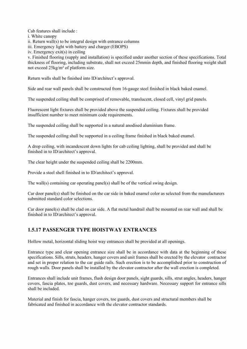
Cab features shall include : i. White canopy ii. Return wall(s) to be integral design with entrance columns iii. Emergency light with battery and charger (EBOPS) iv. Emergency exit(s) in ceiling v. Finished flooring (supply and installation) is specified under another section of these specifications. Total thickness of flooring, including substrate, shall not exceed 25mmin depth, and finished flooring weight shall not exceed 25kg/m² of platform size.
Return walls shall be finished into ID/architect’s approval.
Side and rear wall panels shall be constructed from 16-gauge steel finished in black baked enamel.
The suspended ceiling shall be comprised of removable, translucent, closed cell, vinyl grid panels.
Fluorescent light fixtures shall be provided above the suspended ceiling. Fixtures shall be provided insufficient number to meet minimum code requirements.
The suspended ceiling shall be supported in a natural anodised aluminium frame.
The suspended ceiling shall be supported in a ceiling frame finished in black baked enamel.
A drop ceiling, with incandescent down lights for cab ceiling lighting, shall be provided and shall be finished in to ID/architect’s approval.
The clear height under the suspended ceiling shall be 2200mm.
Provide a steel shell finished in to ID/architect’s approval.
The wall(s) containing car operating panel(s) shall be of the vertical swing design.
Car door panel(s) shall be finished on the car side in baked enamel color as selected from the manufacturers submitted standard color selections.
Car door panel(s) shall be clad on car side. A flat metal handrail shall be mounted on rear wall and shall be finished in to ID/architect’s approval.
1.5.17 PASSENGER TYPE HOISTWAY ENTRANCES
Hollow metal, horizontal sliding hoist way entrances shall be provided at all openings.
Entrance type and clear opening entrance size shall be in accordance with data at the beginning of these specifications. Sills, struts, headers, hanger covers and unit frames shall be erected by the elevator contractor and set in proper relation to the car guide rails. Such erection is to be accomplished prior to construction of rough walls. Door panels shall be installed by the elevator contractor after the wall erection is completed.
Entrances shall include unit frames, flush design door panels, sight guards, sills, strut angles, headers, hanger covers, fascia plates, toe guards, dust covers, and necessary hardware. Necessary support for entrance sills shall be included.
Material and finish for fascia, hanger covers, toe guards, dust covers and structural members shall be fabricated and finished in accordance with the elevator contractor standards.

Entrance Frames: Hoist way entrance frames shall be finished in to ID/architect’s approval.
Door Panels and Sight Guards: Hoist way door panels and sight guards shall be finished in to ID/architect’s approval.
Entrance Sills: Entrance sills shall be constructed of extruded aluminum.
All hoist way entrance frames shall have a square profile.
Standard entrance jamb tactile markings (i.e. jamb plates) shall be supplied on both jambs, at all floors.
Plates shall be finished to match hall fixture metal finish.
1.5.18 ELECTRONIC DOOR SAFETY DEVICE
The elevator car shall be equipped with an electronic protective device extending the full height of the car door. When activated, this sensor (min 4 sensors) shall prevent the doors from closing or cause them to stop and reopen if they are in the process of closing. The doors shall remain open as long as the flow of traffic continues and shall close shortly after the last person passes through the door opening.
1.5.19 LIFT PITS
Emergency mushroom head buttons shall be installed in the lift pit which, when activated, shall instantly stop the car and isolate its supply. Buttons shall be of the 'stay put' type.
These buttons shall be positioned adjacent to the pit access door or ladder such that it can be operated before inspection personnel enter the pit and also when they are within the pit, and shall be engraved run/stop.
A socket outlet controlled by a local RCD shall be provided in the lift pit by the Contractor. The pit access ladders shall be painted safety yellow & provided by Contractor.
1.5.20 MAINTENANCE AND SPARES 1.5.20.1 Maintenance
The Contractor shall furnish maintenance for the entire lift equipment supplied and installed under this Contract for a period of twelve months from date of the Employer’s Representative's Certificate of Practical Completion for the Section. This maintenance shall include systematic and periodical fortnightly examination, adjustment, and lubrication of all lift equipment plus 24-houremergency calls out. The Contractor shall also repair or replace electrical and mechanical parts of the lift equipment whenever this is required and shall use only genuine standard parts produced by the manufacturer of the equipment concerned. Renewals or repairs necessitated by reason of negligence or misuse of the equipment, or by reason of any other cause beyond the control of the Contractor, except ordinary wear and tear shall not be the responsibility of the Contractor. All work under this maintenance provision shall be performed by competent personnel under the supervision and in the direct employ of the Contractor. At the end of the maintenance period, the Employer’s Representative will carry out a further test on the lift plants and any defects shall be rectified by the Contractor without charge to the Employer.
The Contractor shall submit with his tender a totally comprehensive maintenance proposal for all the lifts for a period of three or five years after the first twelve months’ defects liability period.
1.5.20.2 Spares Parts

The Contractor shall provide all spare parts necessary for proper maintenance of the lifts during the defects liability period.
The Contractor shall also supply a list of manufacturer’s recommended spare parts for 1-year operation.
1.5.20.3 Special Tools and Maintenance Equipment
The Contractor shall provide a complete set of special tools and maintenance equipment for maintenance, testing and emergency operation of each of the lifts covered under this Contract. The set of special tools and maintenance equipment shall be in accordance with the recommendations of the manufacturers of the lift equipment and machinery and shall include all necessary items for emergency rescue operations. The special tools and maintenance equipment shall be contained in freestanding, lockable cabinets of approved design and shall be delivered and installed at locations approved by the Employer’s Representative.
1.5.21 TESTING AND COMMISSIONING
1.5.21.1 General
The Contractor shall be responsible for all the tests required to ensure the proper function and operation of the lifts and service hoists under this Contract.
A minimum of seven days’ notice shall be given to the Employer’s Representative, or his representatives, before any testing and commissioning operations are commenced on site.
1.5.21.2 Lifts
Before the lifts are accepted and put into service on the specified maintenance period, each shall, under the supervision of the Employer’s Representative, satisfactorily pass the following tests: -
a. 10% overload test. b. 30 minutes full load test. c. Lift motor current and speed test. d. Door inspection and test. e. Electrical insulation resistance to earth test f. Earth continuity resistance test. g. Safety gear test. h. Buffer test. i. Break test. j. Electrical protective device tests. k. Leveling device tests. l. Automatic Rescue Device test.
Generally the lift shall be made to run under various loading conditions from no load to 10% overload in order to check its operation and floor finding accuracy.
The 10% overload test is to ensure that the equipment installed has ample safety margin, above the rated load incorporated in the design and it is not expected that the floor leveling as guaranteed under full load conditions will be maintained during the overload test.
1.5.21.3 Lift Testing and Commissioning
The lift shall also be subject to a 30 minutes test with the car fully loaded during which it shall stop at each floor on the up and down trips, opening and closing its doors at each stop. The test shall be continuous, the

stops being ten seconds maximum duration, with the door open or alternatively the number of starts per hour shall be as stated in the specification. During the test, the equipment shall not overheat, spark excessively, become noisy or operate in a faulty manner.
All the tests shall be carried out by the Contractor’s Chartered Electrical Engineer and the results shall be signed and recorded in a tabulated form for easy checking and reference.
1.5.21.4 Other Tests
The Contractor shall also carry out any other tests required by the Employer’s Representative or the Government Authorities in order to prove that the equipment complies with the contract documents, codes, rules and regulations covering equipment supplied under this Contract.
1.5.21.5 License To Operate Lifts
The Contractor shall complete all necessary Forms, Submissions and Certificates which must be duly signed by the Contractor’s Qualified Chartered Electrical Engineer carrying out the tests and forward them to the Employer to enable the Employer to obtain the entire necessary License to operate the lifts.

2. FIRE DETECTION AND PROTECTION SYSTEM
2.1 General
This section outlines the minimum acceptance standards for equipment and materials which are to be provided. Any deviation therefrom or alternative offer of materials must be approved by the Architect prior to placement of orders.
Minor equipment and materials not specified herein shall be provided in accordance with the best trade practice.
2.2 Standard & Codes
Fire Detections & Protection System should comply with following standards.
• Fire extinguishing systems - BS EN 3. • Foam fire protection system - BS EN 13565. • Fire extinguishing installations and equipment’s - BS 5306 • Fire Detection and Fire Alarm System - BS EN 54-20 • Fire Hose reel system - BS EN 671-2011 • Fire Wet riser system - BS 9990:2006
The Supply, installation and commissioning of the Fire hose reel system and wet riser system shall be in 100% compliance to British Standard excluding requirement of fire Engine in addition to their compliances to relevant Local Authority Fire Department Regulation.
Pipes should be sized using hydraulic calculation method in accordance with the recommendations of BS- EN-12845.
The development has all its common areas protected by an automatic fire alarm system. Manual break glass and alarm bell will be provided to all floors. All fire alarms will be monitored by the main fire panel in the Fire command center. Mimic-panels will be provided on every lift lobby with the ability to interconnect with the main and other sub-panels to form a loop control in ensuring its reliability
• Do not use firefighting water pipes to supply water for other purposes. • Support horizontal pipes at intervals not exceeding 3 m. • Support vertical pipes at every floor. • Install hangers without regard to location of pipe sleeves through walls. Center pipes in sleeves and do not use sleeves for pipe support. Attach to concrete ceilings with expansion bolts. • Fire pump relief valve, when required, should be piped back into the suction, except where on-site storage tank is available.
2.3 Technical Specifications for Wet Riser/Fire Hose reel System
2.3.1 Scope of Work
The System shall comprise of the following works to provide fully operational system:-
• 100 mm dia. Wet riser piping, valves including pressure regulating valves, canvas hose, hose cradle, coupling and nozzle, Pressure reducing Valves, Fire Hose reels.
• 4-way breeching inlet connected to the fire riser.

The installation shall be complete in every respect, including all fittings, materials and accessories necessary for the complete functioning of the system.
2.3.2 Piping Materials
Unless otherwise specified, all pipes used shall be hot dipped galvanized wrought steel pipes to BS EN 10255, Heavy Duty. All piping shall be new and free from defects. The pipe fittings shall be malleable iron and wrought iron galvanized conforming to the following British Standards:
• B.S 143 Malleable C.I Pipe Fittings • B.S 1256 Malleable C.I and Cast Copper Alloy Pipe Fittings • B.S 1740 Wrought Pipe Fittings.
Pipe joints shall, except otherwise indicated, be screwed and socketed joints. Welded joints shall not be used. All screw threads shall be made up to full depth of the socket and shall be cleaned and square with the axis of the pipe bore. Only Teflon or equal approved P.T.F.E thread sealing tape shall be used in jointing. Hemp or similar organic substances shall not be permitted.
An all piping, bends shall be long radius bends with turning not less than five time the pipe diameters. If this cannot be achieved, alternative bends of approved type shall be used.
Reduction in the diameter of through-flow pipes shall be by means of reduction sockets. Eccentric reducing sockets shall be used on horizontal pipes and concentric reducing sockets on vertical pipes only.
2.3.3 Hose Reel Assembly
The hose reel assembly shall be of either fixed or recessed swing-out type as indicated, being suitable for swift withdrawal of the hose in any direction.
Each hose reel assembly shall consist of a rubber hose, a metal reel, a stop valve, a hose guide and nozzle. The whole hose reel assembly is permanently connected to the water supply.
The reel shall be of metal construction of not less than 8 in. (200mm) inner case diameter and not more than 30 in. (750mm) rim diameter. It shall extend not more than 18 in. (450mm) from the wall or mounting surface. The side plates shall extend at least 1/2 in. (12mm) radially beyond the wound-up hose.
The hose shall be of non-kink smooth bore construction, conforming to the specifications of BS 3169 and rated for a bursting pressure of not less than 600 psi (4.14 MPa). The nozzle assembly shall be constructed of gunmetal, brass or other sufficiently robust and corrosion- resistant material. The nozzle shall be permanently marked to indicate the open and shut position. Product should be UL listed or FM approved.
The whole of the hose reel assembly shall rotate on the horizontal axis and the water supply connection to the hose shall be arranged such that the hose is not obstructed or kinked when the hose is wound up. The piping from the stop valve to the hose reel shall be of non-ferrous material or galvanized.
Wherever necessary, a pressure reducing valve or orifice plate shall be provided for the hose reel for controlling the static pressure to within 18-30 psi (0.12 - 0.2 MPa). The nozzle shall be adjustable for spray and jet discharge.
Every hose reel assembly shall bear the name of the manufacturer and the instructions for operation. Where hose reels are located in recesses or in non-prominent positions, a notice bearing the words “FIRE HOSE

REEL” in red letters on a white background shall be provided. Hose reels shall be provided with recessed housing.
2.3.4. Breeching Inlets
The breeching inlet shall be of 4-way breeching in connections. Each inlet shall consist of a 2 1/2 in. (65mm) instantaneous male coupling and back pressure valve and protected by a cap secured with a suitable length of chain. A drain of 1 in. (25mm) diameter complete with drain valve shall be fitted at the lowest points of the riser. Product should be FM approved or UL Listed.
All fittings shall be located on the external wall of the building at ground level to the approval of the Local Fire Brigade and enclosed in a glass-fronted box.
Breeching inlet shall be of types approved by Fire Authority.
The door of the box containing the inlets shall be glazed with wired glass as indicated by the words " DRY RISER BREECHING INLET” painted on the inner face of the glass in 2" (50mm) block letter. It shall be fastened only by means of a spring lock which can also be operated from inside without the aid of a key after the glass have been broken.
The size of the inlet box shall be 22" x 22" x 12" (560mm x 560mm x 305mm) deep with a fall of 1" (25mm) towards the front at the base.
2.3.5. Pressure Regulating Landing Valves
Each landing valve shall be Constant Outlet Pressure Hydrant type and 65mm bore gunmetal with flanged of B.S.P screwed inlet, and 65mm instantaneous female coupling outlet fitted with removable plug secured by a chain. Product should be FM approved or UL Listed.
The valve shall be supplied with a 65 mm bore renewable valve washer for screw down valve and 20mm minimum diameter spindle and 165mm diameter handwheel.
It shall withstand a test pressure of 300 psig (20.7bar) and be marked with Manufacturer's Name. Landing valves shall be installed between 0.90m and 1.07m above level at the Riser Duct as shown inthe accompanying drawing. They shall be installed such that ample clearance is allowed for easy insertion of canvas hose coupling.
Landing valves shall be normally kept in closed position by leather or canvas strap secured by padlock. All padlocks shall be operable by a master key.
2.3.6. Hose
The canvas hose shall be 2 1/2" (65mm) diameter and 30 m/45 m in length capable of withstanding a test pressure of 150psig. The canvas hose shall be of an approved type to the requirements of the local Fire Brigade & product should have UL Listed & FM approved.
2.3.7 Nozzle
The nozzle shall be of approved jet/spray type.
2.3.8 Couplings
Couplings shall be of gunmetal or other corrosion resisting material, which is sufficiently robust to withstand rough treatment.
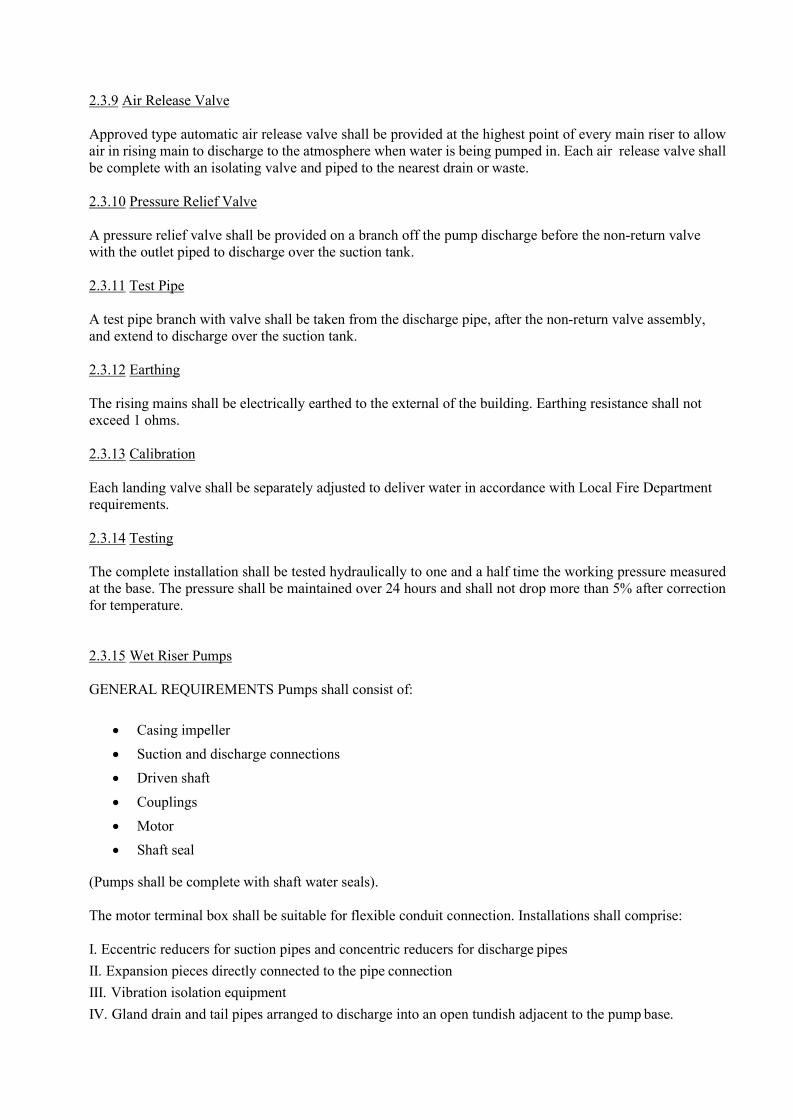
2.3.9 Air Release Valve
Approved type automatic air release valve shall be provided at the highest point of every main riser to allow air in rising main to discharge to the atmosphere when water is being pumped in. Each air release valve shall be complete with an isolating valve and piped to the nearest drain or waste.
2.3.10 Pressure Relief Valve
A pressure relief valve shall be provided on a branch off the pump discharge before the non-return valve with the outlet piped to discharge over the suction tank.
2.3.11 Test Pipe
A test pipe branch with valve shall be taken from the discharge pipe, after the non-return valve assembly, and extend to discharge over the suction tank.
2.3.12 Earthing
The rising mains shall be electrically earthed to the external of the building. Earthing resistance shall not exceed 1 ohms.
2.3.13 Calibration
Each landing valve shall be separately adjusted to deliver water in accordance with Local Fire Department requirements.
2.3.14 Testing
The complete installation shall be tested hydraulically to one and a half time the working pressure measured at the base. The pressure shall be maintained over 24 hours and shall not drop more than 5% after correction for temperature.
2.3.15 Wet Riser Pumps
GENERAL REQUIREMENTS Pumps shall consist of:
• Casing impeller • Suction and discharge connections • Driven shaft • Couplings • Motor • Shaft seal
(Pumps shall be complete with shaft water seals).
The motor terminal box shall be suitable for flexible conduit connection. Installations shall comprise:
I. Eccentric reducers for suction pipes and concentric reducers for discharge pipes II. Expansion pieces directly connected to the pipe connection III. Vibration isolation equipment IV. Gland drain and tail pipes arranged to discharge into an open tundish adjacent to the pump base.

V. Support brackets or plinths incorporating anti-vibration material.
Pumps and supplementary assemblies shall be entirely suitable for the systems pressures and temperatures specified in Drawings or Bill of Quantities. Gate valves shall be provided on suction and discharge. Strainers shall be fitted on the inlet unless otherwise specified. Final pump duties shall be verified taking into account certified resistances of system components. Unless
otherwise specified, pumps shall be to:
I. BS 1394: Parts 1 and 2 II. BS 4082: Parts 1 and 2 III. BS 5257
Pump duties shall be achieved with the impeller shaft speed not exceeding 48rev/s (2900rpm) unless otherwise specified. Where duty and standby pumps are required, provision for automatic changeover shall be made with non-return valves fitted in each pump discharge line.
Pump connections shall be screwed to BS 21 up to DN 50 and flanged to BS 4504, PN 16 for DN 65 and above.
Pump suction and discharge flanges shall be drilled and tapped for pressure gauge connections. Closing plugs shall be supplied.
Pump casings shall have drain plugs fitted at the lowest point. Direction of rotation shall be indicated. All drive connections between drivers (motor or engine) and pumps shall be fully protected against accidental contact. Provision shall be made for shaft speed measurement.
Each pump shall be furnished with splash guards where applicable. Pumps shall be correctly aligned before start-up.
Tied bellows type flexible pipe couplings shall be installed at all pipework connections to pumps. No pump load shall be imposed on the connecting pipework.
Impellers and couplings shall be keyed to the drive shaft, the impeller being retained by a hexagonal nut. Shafts shall be fitted with water deflectors.
2.3.16 MATERIALS OF CONSTRUCTION
Pump Component
Cast Iron
Stainless Steel
High Grade Gun- Metal
Phosphor Bronze
Casing x Seal Housing x Baseplate x Sub frame x Shaft x Impeller x Renewable Casing
Wearing Rings x Glands shall be fitted with a self-adjusting mechanical seal unless otherwise specified.
Impeller shaft extensions shall have a liquid shield.

Generally, materials used for construction shall be:
I. Pump casings : close grained cast iron II. Impellers : cast iron or gunmetal (bronze) III. Shafts : stainless steel.
The permissible service pressure of cast iron pump casings shall be generally in accordance with the manufacturer's recommendations. No pump part or component part shall be subjected to a gauge pressure in excess of 16 bar, except where specifically listed in the Equipment Data Sheets.
2.3.17 PUMP OPERATION
2.3.17.1 END-SUCTION CENTRIFUGAL PUMPS
The pumps shall be selected to suit the type of service encountered. End covers, body rings, bearing, housing and casing shall generally be of cast iron construction. Impellers shall be of bronze or gunmetal and shafts of stainless steel. Case sealing rings, intermediate bushes and water lubricated journal bearings shall be of phosphor bronze material. Shaft seal shall be of high quality gland packed type and bearings shall be ball thrust type on the outboard and self-aligning ball bearing type on the inboard end.
Pump casing shall be axially split or back pull type to permit removal of impeller without disturbing the piping connections. Each pump shall be fitted with an air valve, grease lubricator, water shaft seal connection, copper gland drain fitting and tappings in the pump head casing for discharge pressure gauge. Proper drainage shall be provided for all points around the pump set mounting. Copper gland drain shall be piped to the nearest drain or waste. The pumps shall be constant speed with the pump driver coupled directly to the pump and the whole mounted on a common base plate bolted onto a concrete plinth. The plinth shall be provided to suit the manufacturer's requirements and shall raise the pumps to at least 6in. (150mm) above the known flood level of the pump set location. Mounting of the pump sets on the plinth shall be complete with adequate padding or vibration absorbers.
The hose reel pumps installation shall comply with the requirements of the authority having jurisdiction and the specifications in this contract.
The nominal ratings of the hose reel pumps shall be as specified in the Hose Reel Pump Schedule.
2.3.17.2 ELECTRIC MOTOR FOR FIRE PUMPS
The electric motors shall be AC squirrel cage induction motor of the totally enclosed fan cooled (TEFC) type. The motor shall be in compliance to BS 5000 and of sufficient capacity to effectively fulfill the pump horsepower requirements. The continuous maximum motor rating shall be to BS 2613 and shall have a minimum overload factor of 15% in excess of the power requirements at maximum pump discharge and minimum total head condition.
The motor windings shall be insulated to BS 2757, class `F' and suitably impregnated to withstand damp tropical conditions. Anti-condensation heaters shall be fitted for motors 10 HP and above. Stator frames, end shields, terminal box and cover shall be cast iron or other approved material. Fan and fan cowl shall be of corrosion protected material.
The motor shall be suitable for 415V, 3 phase, 50 Hz power supply. All electrical works pertaining to the motor installation shall be provided. The motor shall be suitably earthed and provided with an overload trip protection. The thermistor protection is not required.

The motor shall comply with all the regulations of the local authorities and be provided with an approved type motor starter to limit the inrush starting current. Starters for the pumps motors shall be direct on line for motor with 1 to 3 Hp, star-delta for motor with 3 to 10 Hp and auto-transformer for 10 Hp and above. The starting current shall not exceed 150% of full load current. Capacitors shall be incorporated where necessary to maintain the power factor of the installation to 0.85 or higher. Unless otherwise specified, motor starters shall be to BS 4941: I. Suitable for three-phase, four-wire 415/240V 50Hz ac supply. II. Fitted with 220-250V ac operating coils.
The pump motor shall generally be flanged motor and suitable for horizontal operation. Coupling between the pump and the motor shall be by flexible self-aligning type complete with bolt-type metal guard. The pump and motor combination shall be mounted on a common base-plate of heavy-duty fabricated steel or cast iron and the complete unit installed on a suitable foundation plinth. The plinth shall be provided to suit the Manufacturer's requirements. Mounting of the pumpsets on the plinth shall be complete with proper drainage and adequate vibration padding or an isolating efficiency of not less than 95% against the lower fundamental disturbing frequency. The minimum acceptable static deflection in the spring and shall be 1 inch (25mm) for machines having a fundamental frequency of 1000 rpm or above, increasing to 1/2 inch (40mm) at 500 rpm. Spring mounts shall be fitted with approved levelling devices.
The electric and power supply to the motor shall be always available. Any switches on the power feed to the motor shall be clearly labelled `POWER SUPPLY FOR FIRE PUMP. DO NOT SWITCH OFF'. An indicator lamp or lamps shall be provided to show that the power is available to the motor. In the event of power failure to the motor starting switch, an automatic warning shall be given visually and audibly at the Main Fire Alarm Control Panel.
The pumping system shall operate as follows:
a) A fall in the piping installation pressure shall activate the pressure switch. b) The pressure switch transmit a signal to the pump control panel with automatically operates the electric booster pump. c) The pump control panel shall indicate the actuation of the pump and transmit a signal to the FIB. d) The FIB shall indicate the operation of the booster pump both audibly and visually. e) Upon failure of the duty pump and/or further pressure drop in the piping installation a second pressure switch shall actuate the standby pump. f) A signal shall be displayed at the FIB and pump control panel indicating the failure of the duty pump and/or the operation of the standby pump.
2.3.17.3 Jockey Pumps
Jockey pumps shall maintain system pressure on the installation side wet riser system. The following general requirements shall apply to jockey pumps:
a) A fall in the system pressure on the installation side of the control value will activate the pressure switch controlling the Jockey Pump. b) The pressure switch transmit a signal to the jockey pump control panel and activates the jockey pump to maintain system pressure on the installation side of wet riser system. c) Jockey pump shall have rated capacities not less than normal leakage rate and sized to make up the allowable leakage within 10 minutes at a rate of flow not exceeding 4 l/min. d) Jockey pump shall have a shut-off pressure not exceeding the working pressure rating of the fire protection equipment. e) The power supply to the jockey pump shall be such that any failure of this pump does not affect the power supply to the main fire pump.
Starter provisions and controls for each jockey pump shall be such that any failure of this pumps panels.

Jockey pumps shall be low capacity in line centrifugal pumps. Pump impeller and shaft shall be stainless with a cast iron casing. Motors shall be totally enclosed, fan-cooled, squirrel-cage type.
2.3.17.4 PUMP NAME PLATES
Each pump shall be provided with a plate giving the output pressure at zero suction lift at the nominal flow rating. Where the performance characteristic of the pump is to be achieved using an orifice plate not integral with the pump delivery, the plate shall carry a reference to the fact that the performance given is that of the pump and orifice plate combination, together with the `K' factor of the orifice plate.
In all case, the pump plate shall give the rated speed for the pressure and flows specified and the maximum power absorbed at the rated speed.
2.3.17.5 CONTROLS FOR FIRE PUMPS
The controller shall be arranged to include the following minimum requirements and specifically tested for fire pump service, all in accordance with Fire Authority Requirements: -
• Manual/Automatic control of the duty and stand by fire pumps with constant output governed by the discharge pressure control situated in the distribution mains.
• Operation of the fire pump sets in a duty/standby mode with manual facility for lead pump selection. The
• standby pump shall be set to come into operation on failure of the duty pump. • The 'OFF-MANUAL-AUTOMATIC' selection sequence shall be controlled by a three-way switch.
Any position other than AUTOMATIC shall sound an alarm. • In addition to the automatic and manual starting systems, the control panel shall be provided with a
device that will enable the pumps to be started from the control circuit in case of any failure. • Operation of the controls shall be possible from the front of the panel without the need to open the
panel doors. • Pressure switches shall be provided for the starting of the pumps when the pressure in the fire service
distribution main falls to a value not less than 80% of the rated operating pressure unless otherwise specified. The pressure switches shall have independent high/low calibrated adjustments and be able to withstand a hydrostatic pressure of 300% of the rated working pressure for five (5) minutes.
• Once started, the pumps shall run continuously until manually stopped or when the system pressure has reached the cut-out pressure setting. Starting of the pump(s) shall at the same time initiate a visual and audible alarm.
• The controllers shall be provided with pilot lights, common alarm bell and individual contacts for the connection of remote signal devices which operate in the event of the following: -
o AC power failure o Failure of duty pump to start o Failure of standby pump to start
• Provision in the form of contacts shall be included for the connections for remote alarm and signals • which correspond to the pilot lamps in the controller. • All alarm and signals shall be able to operate under manual as well as automatic conditions. • Audible alarms shall be of minimum 85-dBA rating at a distance of 5 m. • An electric motor lockout shall be provided for dis-connection of any wires that interconnect the
electric motor control and shall not interfere with the proper operation of either controller. • The fire pumps shall be monitored by the Main Fire Alarm Panel.

2.3.17.6 PUMP CONTROL PANEL
The fire pump control panel shall be a self-contained, extensible, wall- mounted flush-fronted metal cubicle board completely assembled, wired, and tested by the Fire Pump Supplier/Installer before delivery from the Factory. The controller shall be so arranged as free standing independent from the pumps and the contractor shall indicate if the controller is to be supplied with the enclosure designed to be inspected and service from the rear. The controller shall be fixed not further than 3 m from the pump, and be within sight of the driver.
The pump control panel shall be designed to receive an electrical supply of 415/240 V, 3 phase, and 50 Hz AC current. All motor starters shall be incorporated within the control panel. The control panel shall incorporate spare contacts that will close upon operation of the electrical and/or any warning signal. The contacts shall energize a remote electrical bell/or lamp within the main Fire Alarm Panel.
All switches, which are required to keep the controller in the `Automatic' positions shall be within locked cabinets having break glass panels.
All other items as required or standard to, the manufacturer's equipment shall be supplied.
2.3.17.7 PUMP PERFORMANCE TESTS
The fire pumps shall be tested for its performance prior to delivery to site at the pump manufacturer's factory. The pump casing hydrostatic test shall also be carried out in accordance to the Hydraulic Institute Standards. All testing certificates shall be submitted to the Engineer for approval prior to delivery.
The fire pumps shall also be tested for its head/flow characteristic under normal operating conditions after the installation.
• Pump Efficiency
Pump efficiency shall not be less than the following:
Shaft kW Minimum Efficiency
Up to 1 kW 0.35 1 to 2 kW 0.5 2 to 5 kW 0.6 5kW and above 0.7
2.4 Technical Specifications For Portable Fire Extinguishers
2.4.1. General
The Sub-contractor shall supply and install portable type fire extinguishers in the location as shown in the drawings.
All extinguishers provided shall meet with the requirements of the Local Fire Authority and with the relevant BS and NFPA Standards.
2.4.2. LOCATION AND INSTALLATION
Extinguishers shall be conspicuously located where they will be readily accessible and immediately

available in the event of fire. They shall, in general, be located along normal paths of travel and not to be obstructed or obscured from view.
In locations where visual obstruction cannot be completely avoided, means shall be provided to indicate the location.
Hangers, hooks and mounting brackets used for the installation of the extinguishers shall be to the approval of the Engineer. Where extinguishers are installed under conditions subject to dislodgement, such brackets shall be specifically designed to cope with the problem. Extinguishers installed under conditions where they are subject to physical damage shall be protected from impact. The exterior finish of the extinguishers shall be suitable for external or internal location as required. All extinguishers shall be installed such that the extinguisher operating instructions face outward. Extinguishers having a gross weight not exceeding 40 lbs. (18 kg) shall be installed so that the top of the extinguisher is not more than5 ft. (1.5m) above the floor. Except for wheeled types, all heavier extinguishers shall be so installed that the top is not more than 3 1/2 ft (1m) above the floor. In no case shall the clearance between the bottom of the extinguisher and the floor be less than 4 in (0.1m).
The words 'FIRE EXTINGUISHERS' shall be painted using luminous paint on the wall above where the fire extinguisher is installed.
2.4.3 Approval from Fire Authority
The contractor shall be responsible for obtaining approval from the Local Fire Authority for all extinguishers installed. The approval fee required for this purpose shall be deemed to have been included in the tender price.
2.4.4 Types Of Extinguishers
All extinguishers shall be provided according to the type and capacities as indicated in the drawings. Classifications of five classes are according to BS4547.
2.4.5 Water Types
These shall be general purpose extinguishers of either gas pressure type, water/CO2 cartridge type, soda acid type or air-charge stored pressure type as specified, being suitable for Class 'A' fires. Each extinguisher shall be supplied complete with plunger, hose and nozzle and mounting brackets. Extinguishers shall comply with BS 1382, BS 138 and BS 3709 as applicable.
Water type extinguishers shall be painted in red.
2.4.6 Compressed Gas Types
These shall generally be CO2 type intended primarily for Class 'B', Class 'C' and Class 'E' fires, being provided complete with alloy cylinder, valve assembly, hose and discharge horn. Extinguishers shall be painted RED, and comply generally with BS 3326 or equivalent.
2.4.7. Foam Types
These extinguishers are intended for use on Class 'A' and Class 'B' fires, and can be either of AFFF type or CO2 cartridge type. They shall comply generally with BS 740 or equivalent.
These shall be installed complete with hose, nozzle and mounting brackets and painted RED in colour.
2.4.8 Dry Chemical Types

These shall be ordinary dry chemical extinguishers (sodium bicarbonate base, potassium bicarbonate base, potassium chloride base or potassium bicarbonate urea base) suitable for use on Class 'B' and Class 'C' fires or multipurpose dry chemical extinguishers (ammonium phosphate base) suitable for Class 'A', Class 'B' and Class 'C' fires. They may be either cartridge/cylinder operated type or stored-pressure type, and generally to BS 3465 or equivalent.
Where specified, they shall be provided with special long-range nozzles. Dry chemical type extinguishers shall be painted RED.
2.4.9 Dry Powder Types
These extinguishers and agents shall be intended for use on Class 'D' fires and specific metals, following special techniques and manufacturer's recommendations. They may be hand portable, cartridge- operated or wheeled models as applicable. The extinguishing agent shall generally be composed of sodium chloride base agent.
The body colour for such extinguishers shall be RED.
2.5 Technical Specifications For Fire Detection & Alarm System 2.5.1. General
The system shall be of the analogue addressable type with voice command feature, microprocessor based, audibly and visually supervised, with detection and alert devices distributed where dictated by Code. The life safety system shall be composed of three subsystems for fire detection and alarm annunciation, emergency voice/alarm, and two-way communication. The system shall be zoned and non-coded.
The following measures shall be taken:
• Interface with other systems such as security and door access systems, firefighting, smoke control, stair pressurization, Building Automation and Control Network (BACnet), standby/emergency power supply, Audio Visual system, elevators, LP Gas etc shall be required, • Standby emergency power supply system shall be provided to ensure continuity of power supply to loads that are essential to life safety such as the fire alarm system, the FCC and Main Communication Room, the fire pump and mechanical equipment used for smoke control procedures and at least one elevator in every bank with power transferable to any other elevator in the bank. • A two-way telephone communication service is to be installed for fire fighters use. This system shall operate between the building central command and every elevator car, every elevator lobby and each floor level of exit stairs. Notification of occupants shall be achieved through a voice communication system.
The basic system components shall be the following:
• Main fire alarm annunciation and control panel MFAC, microprocessor based, addressable type, modular expandable, fully electronic, electrically supervised, divided into main compartments for control, annunciation and amplifiers. The system shall have batteries capable of monitoring the sys- tem for 24 hours and then sounding the alarm for 30 minutes. • Color graphics CRT terminal • Satellite Fire Alarm Panels SFACs for data acquisition, transmission and control. Wiring, between the speakers/horns, visual alert devices, emergency telephone, detectors, and control modules on one hand and the main control panel on the other hand, shall be via the satellite fire alarm panels that have multiplexing

features and amplifiers rated for the required audio load. Each building shall have an SFAC assigned to serve its various floors. • Automatic and manual detectors consisting of smoke, heat, manual, duct smoke and sprinkler water flow. Detectors shall be located to code. • Alarm notification devices consisting of audible alarms (bells, speakers and horns) and visual alarms (strobe lights). The voice alarm system shall be capable of broadcasting pre-recorded messages and have an interface with the fire fighters station at the main panel. The main fire alarm panel or MFAC/SFAC shall house the amplifiers sized in accordance with the number of speakers and wattage. Speakers shall have different tap settings and shall be adjusted on site for optimum performance and maximum coverage. Alert devices shall be designed to ensure a sound level of 15 dB above ambient noise in each area.
• Interface and control modules for releasing of fire rated doors separating fire zones. • Fire fighters communication system consisting of telephone handsets located next to the exits on each floor and in every elevator car and elevator lobby for high-rise structures. • Interface with the Building Management System for smoke management and control, sprinkler and fire pumps and HVAC control and with other systems such as security, standby/emergency power supply, elevators, etc. • Remote repeater panels at strategic locations such as the main entrances. • Data Network: each MFAC/SFAC panel is a node of a network with direct communications into the network but operates on a stand-alone basis. Although performing different functions, each MFAC/SFAC serves as a "peer-to-peer" (equal) partner in controlling network communications. Network information is sequentially transmitted from one node to another.
The fire alarm system shall provide visual and audible warning on main annunciator panel for supervisory signals such as:
• Failure or disconnection of power supply to main control panel • Failure of fuse or protective device • Removal of detector head on any initiating circuit • Break or short circuit in wiring of any initiating or alarm circuit • Valve tamper at fire pumps • Fire pumps running • Fire pumps power loss • Fire pumps phase reversal • Emergency generator on • Emergency generator start failure • Emergency generator low fuel • Emergency generator low oil pressure
Even though an addressable fire alarm system shall be installed, buildings shall still be divided into zones to identify the location of a fire to help reduce confusion. The following criteria shall be followed in the zoning: • A single zone shall not exceed 2000m2. • A zone shall not cover more than one story. • Stairwells, elevator shafts and flue-like openings shall be treated as separate zones. • The two hours fire separations dictated by the architectural requirements shall be used as separate zones.
The work outlined in this section covers the supply of all materials, which shall be new and unused,

equipment and labor necessary for the complete installation, testing and commissioning and handing over in approved working order of the complete system. It shall also be in accordance with rules and regulations of the Local Fire Authority and of the following: -
a. Local Fire Authority b. Fire and Accident Underwriters Association c. BS 5839 Part1: 1988
2.5.2. Equipment Specification
The Main Fire Alarm Panel (MFAP) shall be of the multiple processor based truly Analogue intelligent type, of modular architecture, being of the latest design and manufacture. The FCP shall be suitable for ambient conditions varying between 00C to + 550C, with relative humidity up to 95% non-condensing.
The MFAP shall be manufactured to BS 5750 ISO 9000 quality standards, by an approved and well known manufacturer who provides design, service back up, and spare parts locally.
The processor system shall as a minimum once per day at the set time automatically adjust all sensing devices to compensate for sensitivity increase due to environmental conditions. This check should also incorporate a full "Check sum" evaluation to detect unauthorized programming changes, or data corruption.
The control panel shall be capable of being extended in modules of 4 loops, up to a maximum of 16 loops. Each 4-loop module shall incorporate its own microprocessor and shall be electrically isolated from the main processor board. The loop board shall incorporate dc/dc converters to prevent loop cross talk. Each converter board shall be provided with step up voltage converter to ensure the correct line voltages are maintained to the detection loops in the event of mains power failure in combination with low battery state.
To increase fault finding capability each loop processor board shall have the LED indicators.
It shall be possible to site a four loop processor board remotely from the main control panel up to maximum distance of 1000 meters and interconnect with the main panel via a four wire screened data line.
Each loop shall be capable of accepting as a minimum 126 Analogue detectors or control devices. The loop PCB will incorporate "on board" short circuit isolators for both the incoming and outgoing loop wiring.
The system architecture and software will allow for random addressing of each device to suit field conditions, pre-set order or soft addressing will not be acceptable.
Each processor shall continuously monitor the Analogue signal from detectors, and evaluate this signal against a pre-determined set of fire algorithms, to accurately determine the existence of fire and to reduce unwanted alarms.
There shall be no limit to the number of detectors per loop which can be in alarm simultaneously, the vacuum fluorescent display (VFD) shall be capable of reporting all incoming alarms by use of a scroll function the scroll function shall be accessible at all times without the need for "key access".
The FAP shall incorporate as standard a vacuum fluorescent display module, which provides, for power conservation reasons, two levels of brightness output. Level 1 output will "low" for standby conditions, with level two providing "high" output, to signal change of state or alarm processing.
The display shall provide up to two rows of 40 characters.
The FAP shall be able to incorporate an integral printer unit, which shall record all changes of state, alarms, faults and operator actions, overall, the minimum requirements will be: -

a) list isolated devices b) list loop devices c) list event log d) list panel outputs e) list loop outputs f) list loop output devices g) list check sums for (programming and Eprom error checking) h) list single device analogue value
The FAP shall be able to be expanded, to the following features. (a) Repeat panel drive (for use to 40 repeat panels) (b) remote printer (ASCII expanded text) (c) mimic driver (d) 32/64/96 way programmable outputs (e) BMS system RS 232 output
2.5.3 Interfacing Facility
2.5.3.1 Interface with Building Automation System (BAS)
The system shall be provided with an RS232 ASCII protocol and to be integrated with the Building Automation System.
2.5.3.2 Interface with the CCTV systems
Provision shall be made for the Fire Graphics and Text workstation to link up with the CCTV system to provide a real time video display at the Fire GT monitor. The Fire Monitor shall display a live video of the camera capturing the fire location in the event of an alarm. A fire signal corresponding to the location of the fire shall be send to the CCTV system by the FACP to activate the CCTV camera such that a real time video picture can be display at the Fire GT monitor.
2.5.3.3 Interfacing works to future fire alarm panels
The Fire Alarm System shall be designed to interface with future fire alarm panels with a maximum of 64 fire controllers on the Network.
The networks shall be totally flexible and enable the fire controllers to be seamlessly linked together, providing a system capability of up to 160,000 detection addresses and over 14,000 digital I/O points.
The Central Fire Command Station shall be configured to monitor the status of all the fire controllers and transmit signals to the fire controllers for specific actions to be performed.
The system shall be able to incorporate the extension of the Fire Alarm Annunciator and Control Panel to provide remote start/stop of equipment such as fans, dampers etc.
2.5.4. Fire Alarm Software
The main processor shall incorporate a "Watchdog" system, which, in the event of processor failure will reboot the system in an attempt to correct the fault and return the system to full operation. Failure to reboot should result in a processor failure being announced both visually and audibly.
All software, program and data shall be held in non-volatile read only memories.
System configuration data shall be stored in memory, which can be electrically erasable or alterable. This system shall be backed up by on board PCB rechargeable batteries with a life span not less than 5 years.

PCB battery should be continuously on charge to ensure correct operation.altered or reconfigured whilst in a live on line situation.
All configured data shall be able to be downloaded to the on board printer for verification and checking purposes.
Alarm processing should incorporate verification scanning before raising any fire or fault signals. The maximum permitted will be:
3 Scans Fire 6 Scans Fault
A priority interrupt signal will be used for all manual break glass units, which will override the scanning process for fire indication.
The processor systems shall include a software routine to enable pre alarm signals to be raised in the event of Analogue signal value from a detector reaching and maintaining a level of 80% of alarm threshold, after multiple scans.
All system configuration data shall be fully field programmable without exception, and shall be able to be
2.5.4.1 Non Alarm Signals
The hardware and software shall be so configured as to allow for incoming "CHANGE OF STATE SIGNALS' Emanating from floor sprinkler control valve isolation including such signals as pump running. The control panel will process this as change of state only and not raise any executive actions or alarms. The internal printer will log such signals to hard print and also to the historical log function of the panel. All non-alarm signals shall be shown visually on the VFD and at the printer as "ALERT" signals only.
2.5.4.2 Walk Test Facility
A walk test facility shall be included which will allow for single man test and verification of loop or zone devices. This testing shall not at any time prevent a fire signal from being generated by devices on other loops or zones, which, will automatically cancel the test function and raise the normal executive actions of the fire system. It shall be possible to inhibit or have on line during the test all field programmable outputs associated with the detectors in the zone or loop being tested.
2.5.4.3 Historical Event Log
The historical log shall have sufficient memory size to log and record up to 200 fire events or combination or events including all operator actions taken. The details held within the log shall be capable of being down loaded to the fire alarm control panel integral printer.
2.5.5, Panel Hardware
The control panel cabinet shall be manufactured from sheet steel of not less than 1.5mm and be undercoated with corrosion resistant materials with final baked enamel paint finish.
Common master LED indication will be provided to give the following information: - a) General Fire b) Supply Healthy c) Pre alarm d) System Fault e) Device Fault

f) External Fault g) Processor Fault h) Device Isolated
2.5.6. Zone Indication
Zone indicators up to a maximum of 96 zones will be provided. Expandable in 64 way membrane sections, all zone indicators shall be LED type. Each membrane will provide zone designation label stripe, which can be inserted from the rear side of each line of indicators.
2.5.6.1 Vacuum Fluorescent Display Panel
The fire alarm control panel display will employ vacuum fluorescent, twin brightness level type display. The two levels of display brightness output will be Level One "Low" (Standby condition) Level "Two" high (Including alarms or panel in access, and operator action).
The overall display will provide two-line output of up to 40 characters per line. The display will provide the following information.
a. Device Type (non-abbreviated) b. Analogue Value c. Device Location d. Device address, zone number loop number e. Normal condition f. Access condition g. Fire alarm h. Device fault i. Pre-alarm j. Fault on loop k. External fault l. Control fault m. Alarm fault n. Supply fault o. Alarms sounded p. Alarms silenced q. Panel reset r. Maintenance mode s. Devices isolated t. Test mode.
2.5.6.2 Sub-Fire Indicator Board (Mimic Panels)
Sub-fire indicator boards (SIB) shall be supplied and mounted remotely from the FIB.
SIBs shall be microprocessor based and include watchdog timers or other appropriate mechanism to ensure ongoing operation. As a minimum configuration, the SIB shall include the following elements.
- Controller microprocessor - EPROM based software - Communications controller - Display (perspex floor plan with colour reverse silk-screen printing) - Display drives - Power Supply
SIBs shall communicate with the FIB by means of a high-level communications interface. This shall

conform to current ISO or CCITT standards and include error detection mechanism. The SIB and FIB shall communicate via an active transmit-respond polling sequence with appropriate timeout and monitoring mechanism.
The SIB shall annunciate the following events. - All flow switch status on a per floor basis. - All pressure switch status inclusive main stop valves shut, low - tank water, pump running etc. - Monitored stop valves status. - Smoke detector groups alarms on a per floor basis and AHU basis. - Pump status. - Installation valve activation. - Power supply and battery charger fault. - System fault status including fault isolated. - Provision for 100% annunciator expansion.
SIB annunciators shall be high quality LED type devices. A LED facility shall be supplied. All displays shall be updated with current system information once every 10 second interval.
The FIB and SIB in conjunction shall supply system software capability including the following.
- Ability to annunciate any system monitored point individually - Be able to add and annunciate new individual or groups monitored points. - Be able to configure point into groups as required and annunciate status of the group on one display. - Test diagnostic to ensure communications integrity.
SIBs shall come complete with cabinet power supply and associate equipment that meet the requirements as specified for the FIB.
2.5.6.3 Master alarm board
The master alarm board shall provide as a minimum, the following common alarm and output facilities: a) Four sets changeover contacts (Two sets isolatable via on board switch). b) 4 alarm sounder monitored output lines rated at 1 amp. each.
c) Switch output for the following: - i. Manual ii. Fault iii. Auxiliary iv. Buzzer v. Alarm vi. Ext. alarm
d) A set of contact common/normal open will be provided which are delayed on power up and power down. This contact will be used for extinguishing system output to prevent spurious signals causing accidental operation of system. e) Visual indicators shall be provided to announce.
i. Alarm fault ii. Earth fault iii. Aux. 1 isolated
2.5.7 Operator Controls The minimum operator control will be as follows: - a) Sound Alarms b) Silence Alarm

c) System Reset d) Scroll Alarms
Access to the operator control must only be achieved by authorized personnel and will only be accessible via a key "ACCESS" switch. Alarm scroll to be available at all times without the need for "Key Access".
A 12 way keypad touch sensitive membrane will provided, providing three levels of users control, level two and three only is accessible on successful entry of a pass number code. The levels will provide the following.
Level 1 (Accessible by key switch operation) a) isolate/de a isolate device b) Set date and time c) List loop devices d) Select test mode e) LED test f) Enable / Disable printer.
Level 2 (Assessable by 4 digit code when in level 1) Facilities a) Print event log b) Read a single device c) List isolated devices (d) Program outputs e) Display checksums
Level 3 (Only available from level two) Facilities a) Print panel outputs b) Print loop devices c) Print loop outputs
2.5.8. Programming
Level two and three shall be extended, when a hand held or portable computer is connected to allow for down-loading/up loading and programming of loop outputs, loop devices and panel outputs. The facilities required from he extended facility will be.
LEVEL 2 LEVEL 3
Message handler Program panel output Program loop devices Program loop outputs Load/Save program data Clear output
2.5.9 LOOP and Field Devices
2.5.9.1 Loop General
The "loop' shall be a two wire circuit starting and returning at the two associated loop return input terminals of the control.
The loop shall be capable of driving as a minimum up to 126 field Analogue Addressable devices offer a maximum total loop distance of 2 km.
2.5.9.2 Loop Communications

The communication to and from each device shall be based on pulse position modulation digitally encoded on the power voltage.
2.5.9.3 Device Addressing There shall be no preset order for addressing the devices. The devices shall be addressed in an order appropriate to site conditions. This order will be determined during commissioning and the control panel will have facility to override the address order to re-check any device showing a tendency to the alarm condition.
2.5.9.4 Loop Short Circuit Isolators Isolators shall be fitted at a maximum spacing of one per 20 devices, or to suit local maximum zone size regulations. The isolators shall protect against short circuits on the loop by isolating that section of the loop where the short circuit occurred, thus maintaining the integrity of the remainder of the system.
Short circuit isolators will be powered by the loop wiring, and will be limited to 10 per loop.
2.5.9.5 Loop Interface Equipment
The loop shall be of receiving information in addition to that from heat and smoke detectors e.g. operation of sprinkler system. The source of this information shall be identified by its own inquire address. Any interface equipment used to achieve this requirement shall be from the standard product range of the same manufacturer as the smoke and heat detectors provided for the loop.
2.5.9.6 Loop Power The loop wiring shall power the detectors, address, and carry data to any from the field devices by digitally encoded signals superimposed on the power voltage.
2.5.9.7 Automatic Devices Identification
The control panel shall be able to identify what type of device is located at each address in order to protect against accidental fitting of an inappropriate sensor.
2.5.10 Detector Common Requirements
2.5.10.1 Detector Power
The detectors shall be suitable for connecting to a two-wire 24 V central system and operate satisfactory within the supply voltage range of 17V-28V DC.
2.5.10.2 Detector Alarm Indication
An indicator LED shall be provided on the detector, which illuminates when the detector has reached a pre- set alarm level. The indicator shall be operated independently of the detector, by a signal command from the central control panel.
2.5.10.3 Detector Remote Output
Provision shall be made for on output from the detector suitable for operating a remote indicator or other device with a current limitation of 4 milli-amps. This output will be initiated by a signal command from the control panel.
2.5.10.4 Detector Mounting Bases
Separate mounting bases shall be required which shall be common in design for all types of detectors to be

used. Bases shall enable ready removal of the detectors for maintenance. The bases shall be fitted with stainless steel terminal springs and stainless steel terminal screw saddles; detector removal will not initiate an open circuit alarm. No detector base shall incorporate electronics of any type.
2.5.10.5 Detector Construction
The construction of the detector and bases shall be in white self-extinguishing polycarbonate plastic. Full circuitry must be protected against moisture and fungus. Smoke entry points will be protected against dust and insect ingress by corrosion resistant gauze. The detectors must be unobtrusive when installed, having a dimension not exceeding 50mm x 100mm diameter maximum, including the mounting base. The detector shall be supplied complete, fully tested and factory pre calibrated.
2.5.10.6 Detector Addressing Method
The unique address of the detector shall be set by the installer by means of a pre coded rigid plug in card, which when fully inserted into the detector base will program the detector address. The coded card when fully inserted will protrude from the detector base, this section of the card will show a pre numbered label for ease of detector identification. In the event DIL or rotary switches are utilized for the setting of address, then part 8.6.2 and 8.6.3 shall apply.
When the address code is set by means of a DIL switch it shall be obscured from sight by means of suitable label. The label shall indicate the relative positions of the DIL switch.
For all detectors with DIL addressing there shall be facility on the mounting base for writing in indelible ink the address of the base. The address code shall be obscured from sight when the detector is fitted to the base.
2.5.10.7 Detector Contamination
The build-up of dirty or similar contamination on the radioactive or optical source will cause the output signal from the detector to gradually change. The control panel shall be capable of monitoring this slow change in signal and at a predetermined level indicate that the detector is in need of servicing or as a minimum false a pre alarm.
2.5.10.8 Approvals
All detectors shall have the relevant manufacturing certificates and accepted for use by relevant authorities.
2.5.11 Detection devices
All analogue addressable field devices shall have an integral microprocessor on board. All this devices shall be BS EN54 LPCB approved. These devices shall include, but not be limited to multisensory detectors, smoke and heat detectors, interface modules and gas releasing and suppression modules.
2.5.11.1 Addressable Intelligent Detectors Each intelligent smoke detector shall be capable of transmitting pre-alarm and alarm signals in addition to the normal, trouble and need cleaning information. It shall be possible to program control panel activity to each level. Each detector may be individually programmed to operate at any one of five (5) sensitivity settings
Each detector shall automatically change to standalone conventional device operation in the event of a loop controller communications failure. In the standalone detector mode, the detector shall continue to operate using sensitivity and environmental compensation information stored in its microprocessor at the time of communications failure. The MFAP shall monitor the loop and activate a loop alarm if any detector reaches its alarm sensitivity threshold.

Every intelligent detector shall be tested periodically for its sensitivity to ensure that the detector continues to operate accurately within its calibrated sensitivity windows. The detector shall be capable of performing independent check on its sensitivity window and should its sensitivity drifted outside this window a fault message shall be reported automatically to the MFAP. System offering this type of feature shall be supported with document from an independent testing authority such as Underwriters Laboratory (UL) or Loss Prevention Council (LPCB).
All detectors must be immune to external Electro-Magnetic Interference conforming to IEC1000-4-8:1995 and ENV 50149:1995/ En 500082-2:1995 and ENV 50140:1993/ EN 50082-2: 1995.
2.5.11.2 Electronic Horn/Strobe All electronic horn/strobes shall be provided according to the drawings.
The horn/strobe shall have a red plastic housing, ultra slim, protruding from the wall less than one inch from the wall. It shall have an attractive appearance with no visible mounting screws. Is shall fits all standard one-gang electrical boxes with plenty of room behind the signal for extra wire.
A sound output level of 91 dBA average shall be provided.
The strobe shall provide 15 cd or 15/75 cd or 30 cd or 110 cd synchronized flash outputs. The strobe shall have lens markings oriented for wall or ceiling mounting. It shall be possible to replace the lens markings with lens marking kits. Ceiling mounted strobes shall have lens markings with correctly oriented lettering. Removal of a installed Horn/Strobe to change the lens markings shall not be acceptable.
Horn/strobe shall mount to a masonry electrical box (2-1/2”deep)
A delay timer with adjustment from 0 to 5 minutes to set off the building alarm bells after a predetermined delay shall be provided. A manual switch shall also be provided to give an immediate alarm.
General: Average ambient sound levels greater than 105 dBA require visible notification appliances. Total sound pressure levels produced by ambient sound pressure levels and all operating audible notification appliances must not exceed 120 dBA within the occupied area.
Public areas In Public areas signals must have a sound level of at least 15 dB above the average ambient sound level or 5 dB above the maximum sound level having duration of at least 60 seconds, whichever is greater. Measurements must be taken with an A-weighted scale (dBA) at 5 feet above the floor in occupied areas.
Apartment Areas mode signals must have a sound level of at least 10 dB above the average ambient sound level or 5 dB above the maximum sound level for at least 60 seconds, whichever is greater. Measurements must be taken with an A-weighted scale (dBA) at 5 feet above the floor in occupied areas.
In sleeping areas, audible appliances must have a sound level of at least 15 dB above the average ambient sound level, or 5 dB above the maximum sound level for at least 60 seconds, or a sound level of at least 75 dB, whichever is greater. Measurements must be taken with an A-weighted scale (dBA) at pillow level in occupied area.
2.5.11.3 Optical Beam Smoke Detector The smoke detectors shall be suitable for detecting invisible product combustion as well as visible smoke and be of the dual chamber dual source type to provide good stability in changing environmental conditions.

Detector coverage will be up to 100m (length) x 15m (wide).
The system shall comprise of a transmitter head, a receiver head and a control box.
2.5.11.4 Ionization Analogue Smoke Detectors
The Ionization smoke detectors shall be suitable for detecting invisible product combustion as well as visible smoke and be of the dual chamber dual source type to provide good stability in changing environmental conditions.
The radioactive source shall be Americium 241 mounted in such a way that it is mechanically secures. The device shall have been certified by the National Radiological Protection Board or a similar body. The detector shall be capable of operating within the following environmental limits.
Temperature operating rang - 20C to 60C
Humidity operating range 0% to 95% RH non-condensing.
Wind resistance up to 10 meters per second without false alarming
The detector shall be capable of protecting an area up to 100m2 at a height of up to 12m. The installation and sitting of the detectors must conform to BS 5839 1980 or similar Standards, ruling in the local region.
2.5.11.5 Photoelectric (Optical) Analogue Addressable Smoke Detectors
The photoelectric (Optical) smoke detectors shall be suitable for detecting visible smoke such as is produced by slow smoldering fires including decomposing PVC. Detector coverage will be 100m2 at a height of up to 12m.
The detector shall be capable operating within the following environmental limits. Temperature operating rang - 20V to 60C
Humidity operating range 0% to 95% RH non-condensing. Wind – non affected.
2.5.11.6 Analogue addressable Heat Detectors
The heat detector shall be electronic in operation and suitable for connecting to a two-wire 24V central system, which can operate within the voltage range of 17V - 28V DC. Detector coverage will be 50m2 at a height of up to 9m.
The device shall monitoring ambient temperature by means of an NTC thermistor. The detector shall be capable of operating within the following environmental limits. Temperature operating range - 20C to +60C (no icing)
Humidity operating range 0% to 95% RH. (Non-condensing) Wind – effected.
2.5.12 Manual Call Stations
2.5.12.1 Break Glass Type
The Manual Call Stations shall be of the break glass type with key lock for test and reset, unless specified otherwise. The break glass unit shall be cast iron, cadmium plated or other approved type and painted red to

BS 381C. The unit shall be of attractive and neat appearance and shall be suitable size and type for surface or flush mounted on the walls. Appropriate label showing “FIRE, BREAK-GLASS” shall be shown on the unit. Breaking the glass cover shall automatically operate the alarm in less than 10 seconds.
2.5.12.2 Analogue Addressable Manual Pull Handle Stations
The Manual Pull handle Stations shall be made of heavy-duty die cast metal or Lexan body and painted red colour. The unit shall be of attractive and neat appearance and shall be suitable size and type for surface or flush mounted on the walls. The unit shall be of a double action type whereby the front cover must be lifted up first before the Pull Handle can be pulled down to initiated an alarm. The unit shall be complete with station reset key. 2.5.12.3 Duct Air Sample Detection
The return air ducting for all zones of HVAC shall be protected by duct mounting detector probe units. The units shall be so designed to minimize the duct preparation work required to install the probe unit. The structure of the duct will be breached only for the insertion of the sample tube by means of two 25mm holes. The duct housing shall incorporate a polyester clear see thorough top, which will allow the detector, and detector led to be clearly seen from ground level.
The housing will be suitable for air sampling in air velocities of not less than 1m per second up to maximum of 20m per second. The velocity across the sample chamber sill is reduced to approximately 1% of the air velocity of the HVAC airflow. Probe units will be installed in straight lengths of the duct, which are not less than 6 times the width of the duct section to ensure least turbulence at the probe unit.
2.5.13. Interface Module Common Requirements
Each interface unit for switch monitoring or output will have use DIL switched to set the address and will be of the same protocol and manufacture. As the detection devices, all interface modules will be supplied complete with LED indicators, which shall illuminate on the operation of the interface device.
2.5.13.1 Switch Monitor Units
Switch monitor units shall be provided to allow conventional to analogue connection for such devices as sprinkler flow switches, floor valve isolation (if applicable) or any such clean contact device as could be deemed necessary for inclusion within the fire system. The switch monitor unit shall be capable of receiving contact configurations of normally open or closed loop. All switch-monitoring units will be powered by the loop wiring without the need for external power source.
2.5.13.2 Input Output Units
Input output units will be provided for the connection to such items as pump start control, lift homing control, or local HVAC shut down. As standard each input output module will corporate a set of change offer contacts to interface with the required service. The input output device shall be capable of being programmed at the control panel to allow for operation by any device on any loop. A separate 24-volt dc input will be required for the input output modules this supply must be derived from a monitored source and is battery backed up.
2.5.13.3 Sounder Circuit Controllers Analogue addressable sounder circuit controllers shall be required; each unit shall have a unique address and be completely programmable from the fire alarm control panel. Each unit shall have a minimum output of 750 milli-amps. The addressing and switching power supply for the controller will be derived from the loop supply. However, the unit shall require a 24V d.c. supply to power the connected alarm load this supply must be derived from a monitored source and be battery backed up.

2.5.13.4 Multi Input Output Controller Multi input output controllers shall be used for the collection of existing conventional detection or clean contact input devices. All input signals to the multi-input module will be fully monitored for open and short circuit. The multi-input unit will have minimum 8 inputs and 8 fully programmable outputs, with 2 monitored output circuits for external alarms.
The unit will be provided with 8 alarm and 8 fault LED indicators with internal buzzer and alarm silence control. The unit will generate 8 unique addresses for the conventional input lines and be fully compatible with the detector and main fire alarm control panel protocol.
Multi input output controllers will be used for the collection of the building Fire Water and Fire pumping signals suitably programmed to transmit ALERT/CHANGE OF STATE signals to the main fire alarm control panel. The following inputs will be required.
a) Pump start b) "A" Pump Running c) "A" Pump Fail d) "B" Pump Running e) "B" Pump Fail f) Water High g) Water Low h) Low Pressure
The following programmed outputs will be required.
a) Pump Start (Programmed from pup start input signal and from fire panel, break glass or sprinkler flow switch alarms) b) Pump changeover (Programmed to switch from pump "A" to pump "B" in the event of pump "A" input failure signal being received).
2.5.14. Standby Power Supply Equipment
The overall fire alarm system will be complete with a 24V D.C charger unit completes with sealed lead acid maintenance free batteries. The charging equipment will be of the approved type and be calculated in size to provide full standby back up load for a period of not less than 24hrs. with a full alarm, load for a minimum period of 2 hrs. The battery and charger unit will be supplied in a sheet steel lockable cabinet of the same construction and finish as the main fire alarm control panel.
2.5.14.1 Battery Calculations The full alarm load will be calculated for a period of two hours to ensure the battery terminal voltage is sufficient not to cause permanent damage to the battery cells. The charger output should be sufficient to run the full alarm load of the system in the event of battery failure. The output shall also be of sufficient capacity to run the full standby load of the system and fully recharge the battery within a 24 hour period.
2.5.15. Field Installation
Two cable system types are approved namely a) Mineral insulated copper covered (M.I.C.C) b) Fire resistant cable of the approved type.
Loop cables should be run separate of all other services including alarm power circuits for alarm outputs.
The minimum permitted core size will be 1.5mm2. For loop lengths of up to 1000 meters, 2.5mm2 will be used for 1000 meters to 2000 meters lengths.

2.5.15.1 Cable Terminations All cable terminations at detectors and break glass devices will use spade type crimp connectors; all devices, which have standard enclosed terminal blocks, will use crimp pins for final termination.
2.5.15.2 Cable Markers All cable cores will be identified using ferrules to provide numbering and symbols as required.
2.5.15.3 Spare Capacity Each loop will populate to 80% capacity, providing 20% spare for future expansion and or change of use.
2.5.15.4 Hard Copy Program The successful contractor shall supply for approval hard copies of all text programming information, including all input to output configurations.
3. ELECTRONIC ACCESS CONTROL SYSTEM (EACS)
Section 1
3.1 Application of the section Items described under this section shall apply to all the sub sections of this specification
3.2 General
3.2.1 This specification covers the submittals of shop drawings, sample approvals, setting to work, supply, installation, inspection, testing & commissioning, as built drawings and operation and maintenance manuals and periodic maintenance.
3.2.2 The Tenderer’s shall read this section in conjunction with Tender drawings and Bill of Quantities. They shall clarify any discrepancies between tender drawings and Bill of Quantities.
3.2.3 The Tenderer shall submit their offer complying with all the conditions of contract, specification, tender drawings and Bill of Quantities.
3.2.4 EACS System supplier with more than 5 year experience shall supply and install the system. 3.2.5 Specification, drawings and BOQ are meant to provide sufficient information to the tenderers and it
is the contractor’s responsibility to supply and install complete systems to working order. 3.2.6 All the sub systems under this section shall be supplied, installed, tested & commissioned by the
respective contractors.
3.3 Operation And Maintenance Manuals The Contractor shall submit 3 copies of Operation & maintenance Manuals, which shall contain Product literature, Specific operating instructions and Maintenance instructions.
3.4 Approval Of information Submitted The Consulting engineer has the right to decide the adequacy of information submitted by the contractor and request further information as necessary if required

3.5 Testing and commissioning of Systems The contractor shall perform all the equipment and devices testing as directed by the Consulting Engineer. The Contractor shall bear the cost for such tests and any items found defective shall be replaced at no extra cost. Such replaced items shall be re- tested for verification.
3.6 Equipment, Materials, Fittings and Accessories The equipment, material used, fittings and devices shall comply with the Architectural and design criteria, design concepts and performance requirements.
When selecting products the contractor shall consider the space limitations, weight limitations, compatibility with other existing devices and systems.
Contractor shall obtain approval from consulting engineer for all the equipment, material, fittings and accessories before commencing installation.
All the products supplied under this contract shall be guaranteed for a period of one (1) year from the final handover date.
3.7 Product Brands All the Materials, Equipment and Devices and Accessories supplied under this contract shall bear the Manufacturer names and make. The consulting Engineer has the right to accept or reject any Equipment, Material and device brands based on the past performance records.
3.8 Drawings The contractor shall familiarize himself with the site conditions before preparing shop drawings. He shall verify the dimensions shown in the drawings and advise the consulting engineer any discrepancies.
The contractor shall submit 3 copies of shop drawing for approval. Contractor shall obtain approval for shop drawings before commencing installation work.
3.9 Maintenance Access and Openings The contractor shall provide all necessary access openings where required for maintenance.
3.10 Codes and Standards All equipment, materials and workmanship shall conform to the relevant British Standards, Maldives Standards and codes of Practice. All electrical installations shall comply with 17th Edition of IEE wiring regulations. Keep 30cm distance from electrical and other interference sources or use metal enclosed earthed conduits/trunks if the distance could not maintained.
Use earthed metal enclosure to install control panels in service ducts. The shield of all cables shall be earthed at control panel and the other end should be kept open. Joints in cables shall not be permitted.

Section 2
3.11 SYSTEM DESIGN The system shall be designed taking into account following specification, tender drawing and the client requirement by specialist contractor with experience in the trade to provide a reliable access control solution.
The EACS system must have standalone two door controllers installed in service ducts. It should control two doors, i.e. two proximity readers, monitoring two door sensors, two push buttons & monitor two emergency door release units. Every control panel should be connected to EACS server via Ethernet. The card access rights should be able to programme in EACS software and it could be uploaded to panels. The access rights should be based on combination of weekday, holidays, time zones & card reader. The control panels must be in normal operation even after shutting down the server. The events shall be automatically buffered in control panel until the server comes on line. Subsequently, the buffered events shall be automatically downloaded to server. No data losses shall experience in any condition.
Valid card, Invalid card, Inactive card, Invalid time zones, Door Ajar, Door forced open, Push Button pressing, Emergency door release press events should reported in software real-time and it should be recorded.
The emergency door release unit shall directly disconnect EML power on activation. All alarms should popup and should be audio alerted.
All predefined doors should be open in fire alarm condition. It could be activated through EACS server automatically. A normally open dry contact will be provided at fire alarm panel for fire integration.
The system should able to produce history reports of all events.
The EACS database backup should weekly uploaded to given location automatically (Scheduled backup).
Backups, time & date updates of control panels should be able to scheduled. The panel date & time should be synchronized with server time automatically once a week.
The user rights for system monitoring & card programming (adding, editing & deleting) should be able to separately assign.
Control panel & field equipment shall be modular in construction. Exact location of readers, push buttons, BGU & locks shall be proposed by architect. The positions shown are suggested locations in public areas as shown in the drawings.

3.12 SYSTEM PERFORMANCE CRITERIA The system performance criteria shall follow international agreed standards and local regulations. They shall be, but not be limited, to the following: 1. Door opening on valid card 2. Opening of door for push button 3. Directly disconnects lock power when emergence door release is pressed 4. Proximity reader LED color change in valid card 5. Real-time status reporting and events recording in database 6. Data base backup & restoring 7. (Automatic) scheduled backup 8. (Automatic) scheduled Panel date & time update 9. Manual door opening through EACS software 10. Open door on fire alarm condition
3.13 GENERAL REQUIREMENT OF EACS EQUIPMENT (a) General All equipment to be supplied under this specification shall be new and the current model of a standard product of a Manufacturer of record. A Manufacturer of record shall be defined as a company whose main occupation is the manufacture for sale of the items of equipment supplied.
1. Maintains a factory production line for the item submitted. 2. Maintains a stock of replacement parts for the item submitted. 3. Maintains engineering drawings, specifications, and operating manuals and for the items submitted. 4. Has published and distributed descriptive literature and equipment specifications on the items of equipment submitted at least 30 days prior to the tender issue.
Specifications of equipment as set forth in this specification are minimum requirements, unless otherwise stated, and shall not be construed as limiting the overall quality, quantity or performance characteristics of items furnished in the EACS system. When the Contractor furnishes an item of equipment for which there is a specification contained herein, the item of equipment shall meet or exceed the specification for that item of equipment.
The total EACS system shall be installed so that the combination of equipment actually employed should work as a full functioning system which does not produce any undesirable visual or aural effects such as signal distortions, noise pulses, glitches, hum bars, transients, ghosting, etc.
3.14 REGULATIONS AND CODE OF PRACTICE It shall be the Contractor’s responsibilities to ensure that the whole EACS system shall comply with all statutory, regulations and requirements of all authorities having jurisdiction over the work.
3.15 TESTING The Contractor shall make all the necessary setting of the equipment after installation. The programming of door open time, Shunt times of door sensor shall be adjusted to suit the usage. All settings shall be clearly marked upon final adjustments. The contractor shall carry out performance tests in the presence of the Engineer with prior approved test methodology.

Section 3
Item Specifications
EACS
Technical Specifications
Item Number : 2 . SMART Card Readers
DESCRIPTION Bidder's Response Page No.
Make
Model
Country of origin
Features Smart Card compatibility ISO 15693, ISO 14443B4 on
13.56MHz
Indicators Audio Inbuilt buzzer Host LED control
single tri-color (green-yellow- red)
Tamper output Optical sensor
Output Wiegand output
IP Rating IP55
Mounting Size Switch plate size, single-gang electrical box
Typical Read Ranges 3"
Operating Voltage 5 - 16 VDC from control panel
Operating Temperature 31º to 150º F (-35º to 65º C)
Operating Humidity 5 to 95% relative humidity (non- condensing)
Approvals USA : FCC ,Europe: CE Mark Approval
Other Should work with reader/control
panel/EACS software
Accessories Any required accessory not specifically referred to install/use the equipment

Item Number : 3. Finger Print Readers
DESCRIPTION Bidder's Response Page No.
Make
Model
Country of origin
Features Interface Ethernet TCP/ IP
Fingerprint verification 1:1 and 1:N
Fingerprints templates 500 or better
No. of Transactions 30000.00
Fingerprint sensor Optical fingerprint without film
sensor
USB Interface
Available
False Rejection Rate ≤0.01% or better
Web Server support Available
First In- Last Out Report Available
Multiple shift base extend to two days
configuration Available
Time & Attendance software
Management Included
Finger enrolment software Included
Fingerprint Enrolment Possible
Accessories Any required accessory not specifically referred to install/use the equipment

Item Number : 5. Push Button
DESCRIPTION Bidder's Response Page No.
Make
Model
Country of origin
Features
Type Proximity Operating Voltage 5.0 - 12 VDC (works from
control panel power)
Output Normal open & Normally closed dry contact
Accessories Any required accessory not specifically referred to install/use the equipment
Item Number : 6. Emergency Door Release
DESCRIPTION Bidder's Response Page No.
Make
Model
Country of origin
Features Colors
Green
Output Dry contact, Normally Close/ Normally open two contact, 2A/24VDC
Type Plastic Resettable, No replacing items required to reset when unit is activated
Size Switch plate size, single-gang electrical box
Item Number : 7. Electromagnetic lock with door position sensor
DESCRIPTION Bidder's Response Page No.
Make
Model
Country of origin
Features
Holding Force 1200 lbs

Mount Surface Mount
Construction Magnet & Armature plate
Voltage Spike Suppressor Available
Operating Voltage Dual Voltage 12V / 24 V Door Sensor Available Indication LED dual color Accessories Any required accessory not
specifically referred to install/use the equipment
Item Number : 8. Control Panel
DESCRIPTION Bidder's Response Page No.
Make
Model
Country of origin
Features
Operation server off-line Available Connectivity With server Ethernet
With Proximity readers
Wiegand
Card Database 10,000 cards or better
Transaction buffer 25,000 transactions or better
Access level 100 or better
Holidays 200 or better
Time zone 100 or better
Card reader formats Wiegand format support Credential facility codes
6 or better
Dedicated tamper alarm Available
Dedicated power fail alarm Available
Real time clock Available
Onboard I/O 2 Readers, 8 Supervised inputs, 4 Relay outputs
Operational modes Card only & Card and PIN Anti-Passback support
Local, Global, Forgiveness
Approvals USA and Canada: FCC ,Europe: CE Mark Approval
Humidity 0 to 85% RHNC
Temperature 0 to 50° C

Accessories Any required accessory not specifically referred to install/use the equipment
Item Number : 9. Control Panel Enclosure
DESCRIPTION Bidder's Response Page No.
Features
Type Metal, Powder coated, lockable
-
Size Suitable to install control panel, power supply
Ventilation Suitable for heat dissipation from control Panel/power supply
Tamper
Enclosure door tamper condition reports EACS software via control panel
Knockouts
Provision of knockouts
Accessories Any required accessory not specifically referred to install/use the equipment
Item Number : 10. EACS Software
DESCRIPTION Bidder's Response Page No.
Features
Edition Standard or Professional (Not Express version)
event monitoring Real Time
Alarm monitoring Control and response, including acknowledge, clear and annotate, Audible notification
Door modes PIN Only, Card+PIN, Card or PIN, Card Only
Reporting History Reports, Export facility, database info reports
Anti-pass back Hard or Soft
Floor plan GUI to locate devices
License 5 user clients

Holiday types 2 or better
Card numbers up to 20 digits or better
Database Backup/Restore Available
Scheduling Control panel Sync Available
Manage the system from more than one workstation Available
Server Application supported operating System Windows Server 2012 R
Client Application supported operating system Windows 7 Professional (64 bit)
Database SQL Server 2012 Express or better
operator user right defining Customizable
Accessories Any required accessory not specifically referred to install/use the equipment
Item Number : 11. Smart Card
DESCRIPTION Bidder's Response Page No.
Features
Dimensions 2.125" W x 3.370" H x 0.030" T (5.4cm W x 8.6cm H x 0.076cm T)
-
Finish Gloss White
Construction PVC Laminate
ISO Standards ISO 15693, ISO 14443B4 on 13.56MHz
Operating Temperature -40° - 158° F (-40° - 70° C)
Operating Humidity Operating Humidity - Application AREA 16 or better
Other Should work with reader/control panel/EACS software
Accessories Any required accessory not specifically referred to install/use the equipment
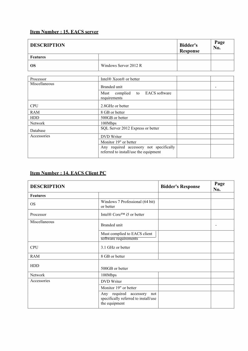
Item Number : 15. EACS server
DESCRIPTION Bidder's Response
Page No.
Features
OS Windows Server 2012 R
Processor Intel® Xeon® or better Miscellaneous
Branded unit
- Must complied to EACS software requirements
CPU 2.8GHz or better
RAM 8 GB or better HDD 500GB or better Network 100Mbps
Database SQL Server 2012 Express or better
Accessories DVD Writer Monitor 19" or better Any required accessory not specifically referred to install/use the equipment
Item Number : 14. EACS Client PC
DESCRIPTION Bidder's Response Page No.
Features
OS Windows 7 Professional (64 bit) or better
Processor Intel® Core™ i5 or better
Miscellaneous Branded unit
-
Must complied to EACS client software requirements
CPU 3.1 GHz or better
RAM 8 GB or better
HDD 500GB or better
Network 100Mbps Accessories DVD Writer
Monitor 19" or better Any required accessory not specifically referred to install/use the equipment

4. CCTV SPECIFICATION
4.1 SYSTEM DESIGN The system shall be designed taking into account following specification, tender drawing and the client requirement by specialist contractor with experience in the trade to provide a high quality uninterrupted CCTV images at each and every viewing points.
The CCTV system shall be capable to handle 512 IP camera streams in 25 frames per second in D1 resolution. IT should be able to handle 1.2 Gbps data throughput. The CCTV system consist of indoor network fixed dome cameras, Outdoor network bullet cameras, pan tilt zoom cameras positioned in the hospital premises. All the cameras streams video to four Network Video Recorders installed in server room. The CCTV control room in ground floor is equipped with dedicated video decoders, monitors and a CCTV network keyboard. The viewing channel changing on monitor, split setup changes & PTZ controlling could be conducted via this keyboard. Any camera shall be viewed in any monitor via keyboard.
The video client software shall be installed in EACS PC in ground floor CCTV room (check EACS client PC configurations, it should match CCTV client software requirements (otherwise provide a CCTV client PC). The image play back & backup shall be conducted via this client PC. The video management server shall manage all user authentication, and video streams with e-map facility.
3m extra cable provision shall be kept inside ceiling for small scale changes. The system should view at highest resolution when single camera is viewed on a monitor. The lower resolution video stream shall be automatically set when multiple cameras are viewed on a monitor. Simultaneous ten client users could be view images simultaneously over the network.
Installer shall provide 30 days of recorded images under D1 resolution, 8 IPS in continuous recording of all cameras. The system shall have provision for expanding NVR storage up to 144TB for each NVR using external storage devices. The NVR should also have provision for RAID levels 0,1,5,6. The system also should have provision for N+1 redundancy of NVRs.
Exact location of cameras shall be proposed by architect. The positions shown are suggested locations in public areas as shown in the drawings.
4.2 SYSTEM PERFORMANCE CRITERIA The system performance criteria shall follow international agreed standards and local regulations. They shall be, but not be limited, to the following:
1. Live video clarity in real time 2. Achieving record duration 3. PTZ tour programming and tour function 4. Image record water mark testing 5. Play back image via calendrer

4.3 GENERAL REQUIREMENT OF CCTV EQUIPMENT 4.3.1 General
All equipment to be supplied under this specification shall be new and the current model of a standard product of a Manufacturer of record. A Manufacturer of record shall be defined as a company whose main occupation is the manufacture for sale of the items of equipment supplied. 1. Maintains a factory production line for the item submitted 2. Maintains a stock of replacement parts for the item submitted. 3. Maintains engineering drawings, specifications, and operating manuals and for the items submitted. 4. Has published and distributed descriptive literature and equipment specifications on the items of
equipment submitted at least 30 days prior to the tender issue.
Specifications of equipment as set forth in this specification are minimum requirements, unless otherwise stated, and shall not be construed as limiting the overall quality, quantity or performance characteristics of items furnished in the CCTV system. When the Contractor furnishes an item of equipment for which there is a specification contained herein, the item of equipment shall meet or exceed the specification for that item of equipment.
The total CCTV system shall be installed so that the combination of equipment actually employed does not produce any undesirable visual or aural effects such as signal distortions, noise pulses, glitches, hum bars, transients, ghosting, etc.
4.4 REGULATIONS AND CODE OF PRACTICE It shall be the Contractor’s responsibilities to ensure that the whole CCTV system shall comply with all statutory, regulations and requirements of all authorities having jurisdiction over the work.
4.5 TESTING The Contractor shall make all the necessary setting of the equipment after installation. The gain, IPS, resolution, recording channel frequencies of camera shall be adjusted to suit the usage. All settings shall be clearly marked upon final adjustments. The contractor shall carry out performance tests in the presence of the Engineer with prior approved test methodology which shall incorporate a spectrum analyser before handling over the system.

4.6 ITEM SPECIFICATION
CCTV
Technical Specifications
Item Number: 2 . Network Video Recorder
DESCRIPTION Bidder's Response
Page No.
Make
Model
Country of origin
Features System throughput capacity 340 Mbps
Throughput allocation @D1 resolution in real time
Live Video 128 channels or better
video playback 20 channels or better
video forwarding 20 channels or better
Network 2 x 1Gbps Ethernet(Dual)
RAID controller SAS 9260 (6Gb/s per port)
Maximum storage support 48TB Storage 30TB Expansionable Maximum total storage 144TB Hardware Redundancy Power supply and
fan module redundancy
Video Compression H.264, MPEG4 Video Resolution 1080P / 720P /
Megapixel / D1 / 4CIF / VGA / CIF
Frame Rate 25 fps (PAL) Recording Mode Time and events, alarm,
manual trigger, continuous video
Hard Disk Hot Plug Support Expansion Interface SAS RAID Level RAID 0, 1, 5, 6 Rack Mountable Support Certification CE, FCC Accessories Any required accessory
not specifically referred to install/use the equipment

Item Number : 3. Video Management Server
DESCRIPTION Bidder's Response
Page No.
Make
Model
Country of origin
Features
Live Video Display with Different Layouts Support
Digital Zoom In/Out Support Instant Playback from live view window Support
Alarm / Event / Status / Log Management Support
Digital Virtual Matrix(Any camera to any monitor) Support
E-map support Support Record searching by time, camera number, event, devices Support
Archive evidence at local storage / central storage / remote site Support
playback modes 8 / 16 / 32 / 64x
Configurable tours and patrols on workstation monitors or video walls Support
Accessories Any required accessory not specifically referred to install/use the equipment
Item Number : 4. Network Video Decoder
DESCRIPTION Bidder's Response
Page No.
Make
Model
Country of origin
Features
Network 1 Gigabit Ethernet
Video Compression H.264, MPEG4
Display Resolution 1080P / 720P / Megapixel / D1 / 4CIF / VGA / CIF
Video Split Full Screen, 2x2, 3x3, 4x4, 6, 8, 9, 13, 16 split screen
Video Output 4 x HDMI ports to digital display screen
Certification CE, FCC

Accessories Any required accessory not specifically referred to install/use the equipment
Item Number : 5. Video Mattrix Controller(CCTV Keyboard)
DESCRIPTION Bidder's Response
Page No.
Make
Model
Country of origin
Features
Joystick 3-axis proportional control
Connection LAN & USB
Password Protection Support Camera Functions Pan/Tilt/Zoom
Program and run presets Program and run tours
Decoder functions change monitor split matrix Assign any camera to any
split screen slot
Accessories Any required accessory not specifically referred to install/use the equipment
Item Number : 6. LED Monitor
DESCRIPTION Bidder's Response
Page No.
Make
Model
Country of origin
Features
Video Input interface HDMI
Design Color
Panel type Wall Mount
Resolution 1366 x 768
Size 24" or better Accessories Any required accessory not
specifically referred to install/use the equipment

Item Number : 7. Outdoor Network PTZ Camera
DESCRIPTION Bidder's Response
Page No.
Make
Model
Country of origin
Features
IP rating IP66
360° continuous rotation Support
True Day/Night (TDN) Support
Wide Dynamic Range (WDR) Support
High Light Compensation (HLC) Support
Zoom 37x
Resolution D1
Presets 50 or better
Tours 4 or better
IR beam 100m
Digital Zoom OFF / ON (X2 ~ X16)
Min. Illumination
IR LED ON - 0 Lux IR LED OFF - Color: 0.02 Lux, F1.6 B/W: 0.001 Lux, F1.6
Focus length f=3.5 - 129.5mm
Iris Control Auto / Manual
Day/Night Auto
Manual Speed 0.1° - 150°/s
Auto Pan Continuous
Dual Streams Support
Network Protocols IPv4, TCP, UDP, HTTP, HTTPS, SMTP, FTP
Frame Rate 1fps - 25fps
Power Supply DC12V
Certificate FCC
Accessories Any required accessory not specifically referred to install/use the equipment
Item Number : 8. Network IR Bulet camera
DESCRIPTION Bidder's Response
Page No.

Make Model Country of origin
Features
IP rating IP66
Power over Ethernet IEEE 802.3af True Day/Night (TDN) Support Wide Dynamic Range (WDR) Support High Light Compensation (HLC) Support Resolution 1080P (1920 x 1080), IR beam 30 - 40m
Min. Illumination
IR LED ON: 0 LuxIR LED OFF: Color: 0.02 Lux @ F1.4 B/W: 0.005 Lux @ F1.4
Focus length 2.8 - 12mm
Iris Control DC IRIS
Day/Night Auto
Dual Streams Support
Network Protocols IPv4, TCP, UDP, HTTP, HTTPS, SMTP, FTP
Frame Rate 1fps - 25fps
Certificate FCC
Accessories Any required accessory not specifically referred to install/use the equipment
Item Number : 9. Network Fixed Dome Camera
DESCRIPTION Bidder's Response
Page No.
Make
Model
Country of origin
Features
Power over Ethernet IEEE 802.3af
True Day/Night (TDN) Support
Wide Dynamic Range (WDR) Support
Resolution 1280x1024
IR beam 15m
Min. Illumination Color: 0.2 lux @ F1.2; B/W: 0 lux (IR on)

Focus length 3.3 - 12mm
Iris Control DC IRIS
Dual Streams Support
Network Protocols IPv4, TCP, UDP, HTTP, HTTPS, SMTP, FTP
Frame Rate 1fps - 25fps
Certificate FCC
Accessories Any required accessory not specifically referred to install/use the equipment
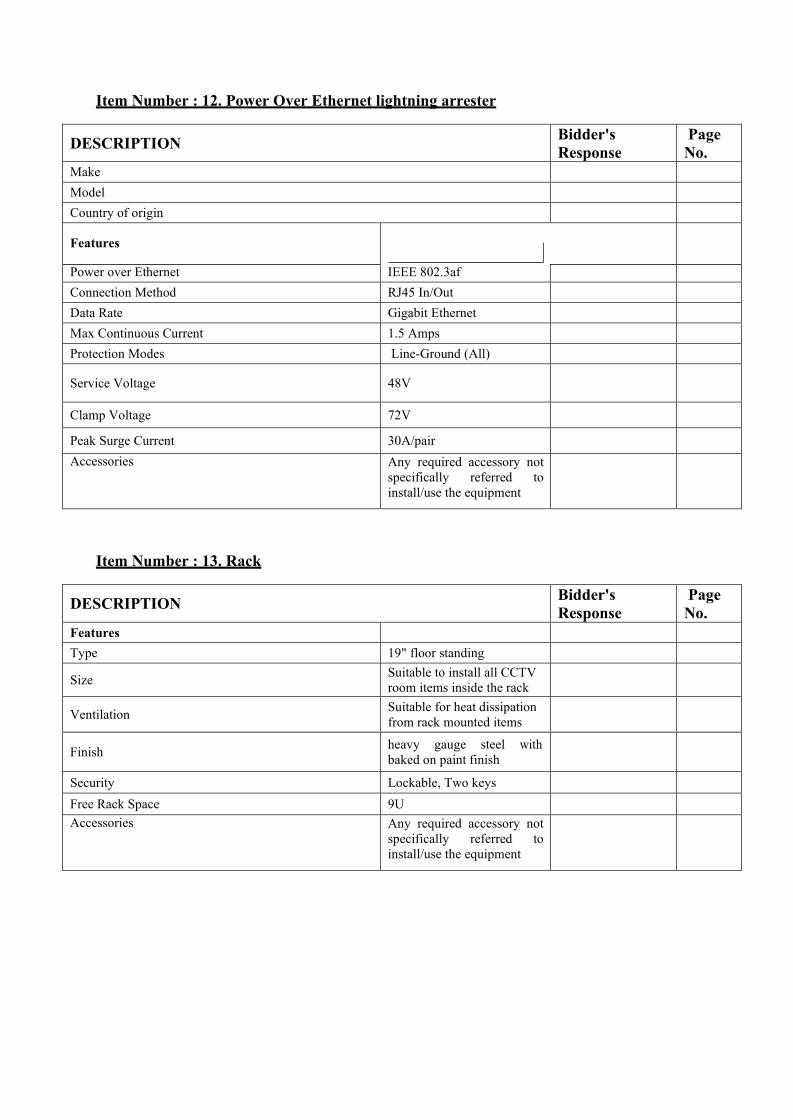
Item Number : 12. Power Over Ethernet lightning arrester
DESCRIPTION Bidder's Response
Page No.
Make
Model
Country of origin
Features
Power over Ethernet IEEE 802.3af
Connection Method RJ45 In/Out
Data Rate Gigabit Ethernet
Max Continuous Current 1.5 Amps
Protection Modes Line-Ground (All)
Service Voltage 48V
Clamp Voltage 72V
Peak Surge Current 30A/pair
Accessories Any required accessory not specifically referred to install/use the equipment
Item Number : 13. Rack
DESCRIPTION Bidder's Response
Page No.
Features
Type 19" floor standing
Size Suitable to install all CCTV room items inside the rack
Ventilation Suitable for heat dissipation from rack mounted items
Finish heavy gauge steel with baked on paint finish
Security Lockable, Two keys
Free Rack Space 9U Accessories Any required accessory not
specifically referred to install/use the equipment

5. MASTER ANTENNA TELEVISION SYSTEM – MATV SPECIFICATION
5.1 SYSTEM DESIGN The system shall be designed taking into account following specification, tender drawing and the client requirement by specialist contractor with experience in the trade to provide a high quality reception at each and every TV outlet of the hospital.
The MATV system shall be capable to distribute 20 standard definition quality video channels with audio which is in DVB-T modulation. The service provider should provide 18 channels of PAL CVBS and analog (L/R) audio outputs. All associated cost of obtaining services from the Dialog TV shall be borne by the client. TV sets which should support to DVB-T shall be supplied by the others but installed by the ELV Contractor. The distribution network also should able to distribute IF signals as a provision for future use.
Encoders and associated equipment shall be modular in construction, rack mounted and designed for easy replacement of amplifiers and major as well as minor components. Front and near access shall be provided.
Exact location of TV Outlets shall be proposed by architect. The positions shown are suggested locations in public areas as shown in the drawings. The number of TV channels allocated as minimum:
Description No. of Channels Standard Definition PAL TV channels
18
In House Channels 2
5.2 SYSTEM PERFORMANCE CRITERIA
The system performance criteria shall follow international agreed standards and local regulations. They shall be, but not be limited, to the following: 1. The required signal level at the TV outlet shall be 50-60 dBuV. 2. The maximum signal level at the TV outlets shall not be more than 60dBuV. 3. Minimum Signal to Noise ratio shall be 19dB. 4. Maximum differences between signal levels a. -3dB (neighboring channels) b. -6dB (within any band 60 MHz wide) c. -10dB (within the whole spectrum
5.3 GENERAL REQUIREMENT OF MATV EQUIPMENT 5.3.1 General

All equipment to be supplied under this specification shall be new and the current model of a standard product of a Manufacturer of record. A Manufacturer of record shall be defined as a company whose main occupation is the manufacture for sale of the items of equipment supplied. 1. Maintains a factory production line for the item submitted. 2. Maintains a stock of replacement parts for the item submitted. 3. Maintains engineering drawings, specifications, and operating manuals and for the items submitted. 4. Has published and distributed descriptive literature and equipment specifications on the items of equipment submitted at least 30 days prior to the tender issue.
Specifications of equipment as set forth in this specification are minimum requirements, unless otherwise stated, and shall not be construed as limiting the overall quality, quantity or performance characteristics of items furnished in the MATV system. When the Contractor furnishes an item of equipment for which there is a specification contained herein, the item of equipment shall meet or exceed the specification for that item of equipment.
The total MATV system shall be installed so that the combination of equipment actually employed does not produce any undesirable visual or aural effects such as signal distortions, noise pulses, glitches, hum bars, transients, ghosting, etc.
All trunk, branches and interconnecting coaxial cables and unused ports/taps shall be terminated with a 75 ohm terminating resistor designed for MATV cable systems without adapters.
5.4 REGULATIONS AND CODE OF PRACTICE It shall be the Contractor’s responsibilities to ensure that the whole MATV system shall comply with all statutory, regulations and requirements of all authorities having jurisdiction over the work.
5.5 TESTING The Contractor shall make all the necessary setting of the equipment after installation. The gain and channel frequencies of each amplifier shall be adjusted to suit the usage. All settings shall be clearly marked upon final adjustments.
The contractor shall carry out performance tests in the presence of the Engineer with prior approved test methodology which shall incorporate a spectrum analyzer before handling over the system.

5.6 ITEM SPECIFICATION
Item Number : 1 . Encoder/Modulator(DVB-T)
DESCRIPTION Bidder's Response Page No.
Make Model Country of origin Features Input Audio RCA for Analog Audio (L, R)
Video RCA for Video (PAL CVBS) Encoding Video Output Format MPEG-2 / H.264
Resolution 480i & 576i
Aspect Ratio 4:3, 16:9 and pass through
Video bit rate Variable, 1.000~19.000 Mbps
Encoding Audio Sampling rate 48 KHz
Output bitrate Variable, (64, 96, 128, 192, 256, 320, 384kbps)
Output Connector “F” Female (loop-through combiner input)
Output/RF Frequency Range
5 - 999 MHz, Programmable to CCIR channels
Output level 115dBμV or better MER 40dB of better Impedance 75Ω
Output/DVB-T COFDM
Modulation format QPSK, 16QAM, 64QAM
Guard Interval Programmable to 1/4, 1/8, 1/16, 1/32
Bandwidth Programmable to 6, 7, 8 MHz Monitoring/Control Local control Full configuration
Power supply External/built-in 195-264 VAC, suitable to power encoder modulator/s
Operating Temperature 32 to 122 / 0 to 50 (ºF / ºC)
Control parameter memory Retains after power off conditions
Accessories Programmer Full configuration with handheld programmer (If required)
Codes
Codes required to receive RCA A/V from service provider's equipment rack located adjacent to MATV rack Any required accessory not specifically referred to install/use the equipment

Item Number : 3. Line Amplifier
DESCRIPTION Bidder's Response Page No. Make
Model
Country of origin
Features
Operating Temperature -5 to +45 ºC
Powering Voltage 196 - 264 AC Signal Input/Out put “F” Female
Signal test out put “F” Female RF - Main MATV Frequency
range 87 - 862 MHz
Gain 40 - 53 (select.) dB or better
Maximum output level(EN 50083)(IMD3)
119dBμV or better
Maximum output level CTB, CSO
106dBμV or better
Noise figure 10dB or better
Attenuator 0 - 18dB or better
Equalizer 0 - 18dB or better
Inter-stage attenuator 0 - 10dB or better
Inter-stage Equalizer 0 - 10dB or better
IF Frequency range 950 - 2150 MHz
Gain 42dB or better
Maximum output level(EN 50083)(IMD3) 2chan
121dBμV or better
Noise figure 13dB or better
Equalizer 0 - 12dB or better
Inter-stage attenuator 0 - 18dB or better
Accessories Any required accessory not specifically referred to install/use the equipment

Item Number : 4. Attenuator
DESCRIPTION Bidder's Response Page No. Make
Model
Country of origin
Features
Frequency Range 5-2200 MHz
Attenuation Margin 0 - 20 adjustable
dB or better,
Connectors “F” Female Accessories Any required accessory
not specifically referred to install/use the equipment
Item Number : 5. Indoor Splitter
DESCRIPTION Bidder's Response Page No.
Make
Model
Country of origin
Features
Frequency Range 5-2400 MHz
Number of outputs As per the schematic diagram requirements
Through loss (Insertion loss) As per the schematic diagram requirements (dB)
Connectors “F” Female Accessories Any required accessory not
specifically referred to install/use the equipment
Item Number : 6. Indoor TAP
DESCRIPTION Bidder's Response Page No. Make
Model
Country of origin
Features
Frequency Range 5-2400 MHz
Number of outputs As per the schematic diagram requirements
TAP loss As per the schematic diagram requirements (dB)

Through loss (Insertion loss) As per the schematic diagram requirements (dB)
Rejection Tap -> Tap 18dB or better Connectors “F” Female Accessories Any required accessory not
specifically referred to install/use the equipment
Item Number : 7. TV Outlet
DESCRIPTION Bidder's Response Page No. Make
Model
Country of origin
Features
Type End Type
Number of connectors 2
TV/FM Connector Male CEI Frequency Range 87-862MHz Tap loss 0.6dB or better
IF/SAT Connector Female CEI Frequency Range 950-2150MHz Tap loss 1.5dB or better
Accessories Any required accessory not specifically referred to install/use the equipment
Item Number : 8. Face Plate for TV Outlet
DESCRIPTION Bidder's Response Page No.
Features
Type
Should be same as the electrical switches series, A modified blank plate could be used (Note)
-
Number of connector provisions 2 Accessories Any required accessory not specifically
referred to install/use the equipment

Item Number : 9. Coaxial extension code (from TV outlet to TV)
DESCRIPTION Bidder's Response Page No. Features
Length 2m or higher -
Coaxial Shielding Cover 75% or better Color White
Connector
"L" shaped Male IEC & "L" shape Female CEI at two ends of extension code
Inner conductor solid, Bare copper -
Outer conductor tinned copper wires braid Outer conductor foil Dual foil Al/pet or better screening coverage 85% or better Outer sheath PVC
Impedance 75ohms
Screen Attenuation
according to EN50117 (30-1000MHz SA >95dB, 1GHz-2GHz SA >85dB)
Operating Temperature -30°C To +75°C
Velocity of Propagation 84% or better
Attenuations @20ºC 19dB/100m @ 800MHz or better
28dB/100m @ 1750MHz or better
34dB/100m @ 2400MHz or better
Accessories Any required accessory not specifically referred to install/use the equipment
Item Number : 11. RG6 Coaxial Cable
DESCRIPTION Bidder's Response Page No. Features
RG Type 6
Inner conductor solid, Bare copper
-
Outer conductor tinned copper wires braid
Outer conductor foil Dual foil Al/pet or better
screening coverage 85% or better
Outer sheath PVC
Impedance 75ohms
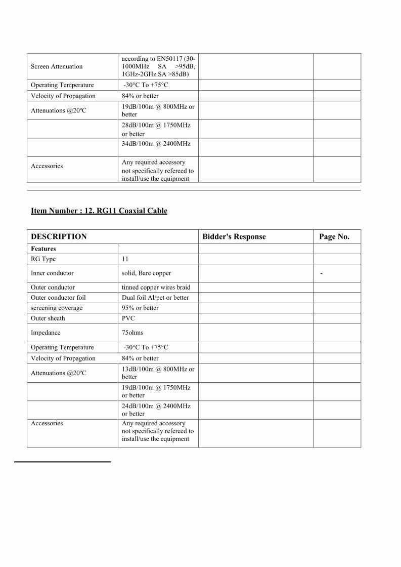
Screen Attenuation
according to EN50117 (30-1000MHz SA >95dB, 1GHz-2GHz SA >85dB)
Operating Temperature -30°C To +75°C
Velocity of Propagation 84% or better
Attenuations @20ºC 19dB/100m @ 800MHz or better
28dB/100m @ 1750MHz or better
34dB/100m @ 2400MHz
Accessories Any required accessory not specifically refereed to install/use the equipment
Item Number : 12. RG11 Coaxial Cable
DESCRIPTION Bidder's Response Page No. Features RG Type 11
Inner conductor solid, Bare copper
-
Outer conductor tinned copper wires braid Outer conductor foil Dual foil Al/pet or better screening coverage 95% or better Outer sheath PVC
Impedance 75ohms
Operating Temperature -30°C To +75°C
Velocity of Propagation 84% or better
Attenuations @20ºC 13dB/100m @ 800MHz or better
19dB/100m @ 1750MHz or better
24dB/100m @ 2400MHz or better
Accessories Any required accessory not specifically refereed to install/use the equipment

Item Number : 14. "F" Connectors for RG11 cables
DESCRIPTION Bidder's Response Page No. Features
Type F compress, Crimping type
-
size correct provided
size for RG11 cables
Accessories Any required accessory not specifically refereed to install/use the equipment
Item Number : 15. "F" Terminal Load
DESCRIPTION Bidder's Response Page No. Features
Type "F" Male - Impedance 75 Ohms Accessories Any required accessory not
specifically refereed to install/use the equipment

Item Number : 16. MATV distribution box
DESCRIPTION Bidder's Response Page No. Features
Type Metal, Powder coated, lockable
-
Size
Suitable to install line amps, taps, splitters and attenuators in service ducts
Ventilation Suitable for heat dissipation from line Amp
Accessories Any required accessory not specifically refereed to install/use the equipment
Item Number : 17. Rack
DESCRIPTION Bidder's Response Page No. Features
Type 19" floor standing -
Size Suitable to install all MATV room items inside the rack
Ventilation Suitable for heat dissipation from rack mounted items
Finish heavy gauge steel with baked on paint finish
Security Lockable, Two keys
Free Rack Space 9U Accessories Any required accessory not
specifically refereed to install/use the equipment

6. NURSE CALL SYSTEM SPECIFICATION
6.1 SYSTEM DESIGN
The system shall be designed taking into account following specification, tender drawing and the client requirement by specialist contractor with experience in the trade to provide a reliable emergency call system.
The user calls for assistance by activating a ceiling pull, standard call point,. A confidence light on the calling device illuminates to reassure the user that the call has been registered. At the system’s indicator panel-Nurse Control Panel (s), an indicator light illuminates and a buzzer sounds to inform staff that someone is in need of assistance. Relevant over door lights (if available) also operate (as fitted) to provide additional visual indication of the call. A member of staff visits the calling room to assist the user and resets the calling device to return the system to normal. The following shows sample items for reference.
The master reset button of system’s indicator panel-Nurse Control Panel should be able to enable or disable as this facility allows standard calls to be globally cancelled without the source of the call being investigated. The “Mute” button allows any standard calls on the system to be silenced but it leaves relevant indicator light(s) lit. Although a new call from a different call point will re- activate the sounder.
Exact location of call points & remote indicators, etc. shall be proposed by architect. The positions shown are suggested locations in areas as shown in the drawings.
6.2 SYSTEM PERFORMANCE CRITERIA
The system performance criteria shall follow international agreed standards and local regulations. They shall be, but not be limited, to the following: The system performance criteria shall follow international agreed standards and local regulations. They shall be, but not be limited, to the following: 1. Test call registering of each call point in Nurse Control Panel 2. Test Visual and audible alert generate at Nurse Control Panel by each call point 3. Test call resetting of each call point

4. Test remote indicator function
6.3 GENERAL REQUIREMENT OF MATV EQUIPMENT General
All equipment to be supplied under this specification shall be new and the current model of a standard product of a Manufacturer of record. A Manufacturer of record shall be defined as a company whose main occupation is the manufacture for sale of the items of equipment supplied.
1. Maintains a factory production line for the item submitted. 2. Maintains a stock of replacement parts for the item submitted. 3. Maintains engineering drawings, specifications, and operating manuals and for the items submitted. 4. Has published and distributed descriptive literature and equipment specifications on the items of
equipment submitted at least 30 days prior to the tender issue.
Specifications of equipment as set forth in this specification are minimum requirements, unless otherwise stated, and shall not be construed as limiting the overall quality, quantity or performance characteristics of items furnished in the Nurse Call system. When the Contractor furnishes an item of equipment for which there is a specification contained herein, the item of equipment shall meet or exceed the specification for that item of equipment.
The total nurse call system shall be installed so that the combination of equipment actually employed does not produce any undesirable visual or aural effects such as signal distortions, noise pulses, glitches, hum bars, transients, ghosting, etc.
All trunk, branches and interconnecting cables and unused ports/taps shall be terminated.
6.4 REGULATIONS AND CODE OF PRACTICE
It shall be the Contractor’s responsibilities to ensure that the whole nurse call system shall comply with all statutory, regulations and requirements of all authorities having jurisdiction over the work.
6.5 TESTING
The Contractor shall make all the necessary setting of the equipment after installation. The call registering, resetting shall be tested in each call point to suit the usage. All settings shall be clearly marked upon final adjustments. The contractor shall carry out performance tests in the presence of the Engineer with prior approved test methodology before handling over the system.
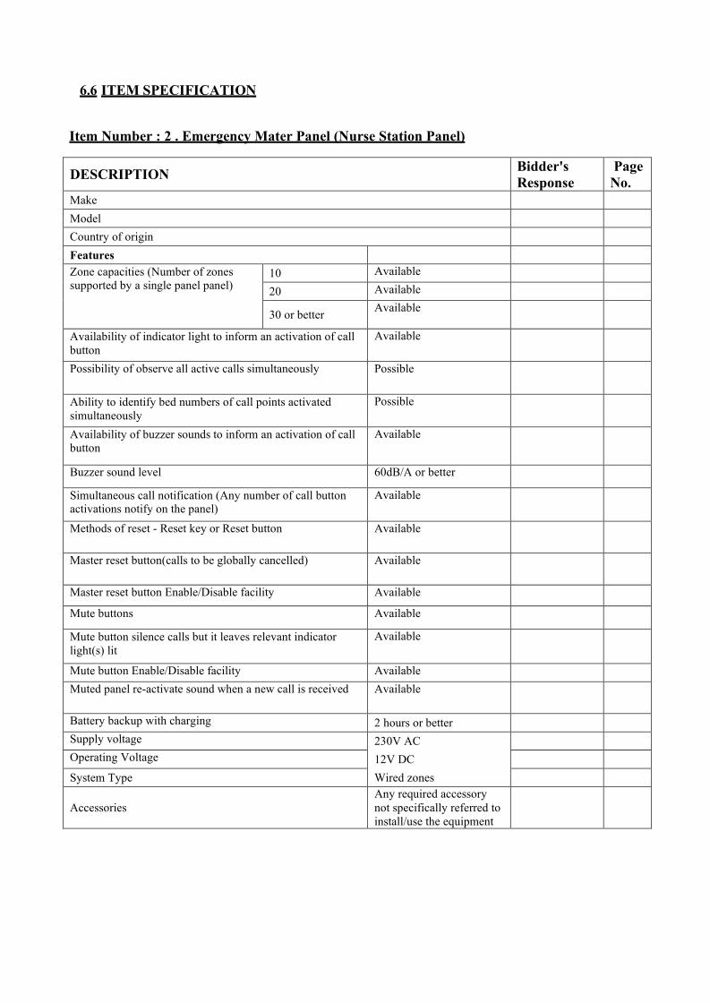
6.6 ITEM SPECIFICATION
Item Number : 2 . Emergency Mater Panel (Nurse Station Panel)
DESCRIPTION Bidder's Response
Page No.
Make
Model
Country of origin
Features Zone capacities (Number of zones supported by a single panel panel)
10 Available
20 Available
30 or better Available
Availability of indicator light to inform an activation of call button
Available
Possibility of observe all active calls simultaneously Possible
Ability to identify bed numbers of call points activated simultaneously
Possible
Availability of buzzer sounds to inform an activation of call button
Available
Buzzer sound level 60dB/A or better
Simultaneous call notification (Any number of call button activations notify on the panel)
Available
Methods of reset - Reset key or Reset button Available
Master reset button(calls to be globally cancelled) Available
Master reset button Enable/Disable facility Available
Mute buttons Available
Mute button silence calls but it leaves relevant indicator light(s) lit
Available
Mute button Enable/Disable facility Available Muted panel re-activate sound when a new call is received Available
Battery backup with charging 2 hours or better Supply voltage 230V AC Operating Voltage 12V DC
System Type Wired zones
Accessories Any required accessory not specifically referred to install/use the equipment

Item Number : 4. Button Reset Emergency Call Point without tail call lead
DESCRIPTION Bidder's Response
Page No.
Make
Model
Country of origin
Features
Powering By Master panel confidence light (Availability of light on the calling device which illuminates to reassure the user that the call has been registered in master panel)
Available
Reset Method Button Reset
Remote socket for tail call lead Available Tail call lead Not available Calling method Button call point Size Standard switch box size,
compact
Accessories Any required accessory not specifically referred to install/use the equipment
Item Number : 5. Button Reset Emergency Call Point with tail call lead
DESCRIPTION Bidder's Response
Page No.
Make
Model
Country of origin
Features
Powering By Master panel confidence light (Availability of light on the calling device which illuminates to reassure the user that the call has been registered in master panel)
Available
Reset Method Button Reset
Remote socket for tail call lead Available Tail call lead Availability Available
Length 1.8m (6ft) Calling method Button call point or
removing tail call lead
Size Standard switch box size, compact
Accessories Any required accessory not specifically referred to install/use the equipment

Item Number : 6. Button Reset Emergency Call Point with ceiling pull code
DESCRIPTION Bidder's Response Page No.
Make
Model
Country of origin
Features
Powering By Master panel confidence light (Availability of light on the calling device which illuminates to reassure the user that the call has been registered in master panel)
Available
Reset Method Button Reset
Remote socket for tail call lead
Not Available
Tail call lead Availability Not Available Calling method Pull code Size Standard switch box
size, compact
Accessories Any required accessory not specifically referred to install/use the equipment
Features
Item Number : 7. Over Door Indicator (Remote Indicator)
DESCRIPTION Bidder's Response Page No.
Make
Model
Country of origin
Features
Indication Light Illumination Size Standard switch box
size, compact
Accessories Any required accessory not specifically referred to install/use the equipment

7.1 GENERAL
7. TELEPHONE SYSTEM SPECIFICATION
The following specification covers the supply, delivery, installation, testing and commissioning of a complete Telephone System including maintenance during the defects liability period. All work pertaining to the system shall be in accordance with these specifications and shall meet all applicable Rules & Regulations of the local telecommunication authority.
The specifications and drawings are intended to provide the minimum basic performance and characteristics for the supply and installation of a complete system and the required standards of workmanship and materials in the design, manufacture, supply, installation, testing and commissioning of the system.
System provided shall be complete and operable, and shall include the required accessories, fastenings and supports. One coat of primer shall be applied for all fastenings and supports.
7.2 TELEPHONE WIRING AND INSTALLATION The entire telephone wiring installation, as shown on the relevant drawings accompanying this document, shall be supplied, installed and commissioned by the Contractor who shall also be a Registered Contractor with the local telecommunication authority. If the contractor is not registered with the local telecommunication authority, he shall then obtain the services of a Registered Contractor and submit the name of such contractor to the Consulting Engineer for approval prior to engaging the services of the said contractor. In the event of the contractor engaging the services of an approved Registered Contractor, he shall be fully responsible for all works undertaken by such Registered Contractor, including all terms and conditions stated under this Contract.
The entire telephone wiring installation shall include all accessories necessary for the completion of the works in every respect and to the satisfaction of the local telecommunication authority, whether such be mentioned in this specification and the drawings or not.
The telephone under floor trunking shall within the building shall be carried out in concealed, rigid PVC under floor trunking of gauges and type approved by the local telecommunication authority. The trunking runs shall be laid in floor screeds below floor finishes. Where possible, the Contractor shall closely liaise and arrange for chases of suitable depths and widths to be cast in the floor screeds to accommodate the trunking, the final concreting of chases shall be undertaken under approval from the Consulting Engineer and local telecommunication authority.
Telephone floor trunking shall, as far as possible, be supplied in lengths to suit the trunking runs. Where joints are unavoidable the joints shall be coated with an approved jointing compound during assembly and be made watertight. All joints shall be so constructed that cables can be conveniently drawn through without damage.
A piece of suitably flexible and strong draw-in-multi-strand wire shall be left in every section of the under floor telephone trunking between adjoining junction boxes. These draw-in wires are for

the running of future telephone cables.
Where riser ducts are used in the building for telephone cabling the scope shall include perforated cable tray covering the whole wide of the riser ducts.
Distribution boxes used outside riser enclosure shall be made of mild steel material 16 SWG minimum thicknesses and fitted with locks. Those distribution boxes used inside locked riser enclosure shall be made of mild steel and fitted with clipped-on-covers.
The junction boxes must be watertight, made of stainless steel with durable screw-on covers of 10 SWG thickness and flush with the floor covering. Telephone outlet box may be round or square as indicated and the outlet hole 6mm diameter in which rubber grommet shall be fitted. Where building structure prohibits the use of trunking of more than 25mm depth, then the width of the trunking shall be increased proportionately.
Telephone outlet and junction boxes shall be of moulded type and type approved by the Consulting Engineer and local telecommunication authority. The boxes shall be recessed in the floors and provided with removable, non-corrodible metal covers (metal covers to be flush with floor finishes.
A gasket shall be provided around the end of each junction box to prevent seepage of water into the box when the cover has been screwed in position. The screws used shall be of non-corrosive type (preferably of brass) and countersunk so that their heads do not protrude above the finished floor levels when installed.
The junction boxes are to be supplied in terminal though way, tee-off or intersection patterns as required on the drawings. The opening where trunking enters each box shall be filled smooth so that the PVC sheath of the telephone cables will not be damaged during installation.
Cable terminal unit used for telephone risers shall be of the galvanised type and generally conform to the requirements for cable trays.
All necessary cable trays used for risers shall be of the galvanised type and generally conform to the requirements for cable trays.
All materials used for wiring must be approved by the local telecommunication authority. Internal telephone cables shall comprise tinned, annealed copper conductors, PVC insulated and PVC sheathed with Grey/Black colour code of conductors according to local telecommunication authority Specification.
7.3 TELEPHONE MANHOLE AND PIT
Telephone manholes and pits shall be constructed according to local telecommunication authority requirements. The manhole and pit shall be of waterproof construction.

If the site selected for a manhole be encroached upon by any obstruction, as for instance, a pipe main, Contractor shall arch the walls round such obstruction, or make other arrangement as may be required by the Engineer.
Conduits shall enter manholes and pits at such a depth to ensure a clearance of at least 450mm between the top of the barrel of the uppermost conduits and the underside of the roof of the manhole or pit.
Where the duct capacity of any proposed manhole is not fully utilized the space shall be fitted with dummy ducts for future duct growth. The dummy ducts shall be sealed with 13mm cement mortar inside the chamber wall.
To ensure that cables can easily be housed in manholes and pits with a minimum of bending, the conduits should be splayed over the last length to enter the manhole and pit equally on either side. The manhole and pit shall be constructed throughout of Class ‘B’ concrete
7.4 EARTHING All necessary earthing requirements for the whole installation should be included in the cost.
7.5 TESTING AND COMMISSIONING The contractor shall liaise with the local telecommunication authority and be responsible for getting the installation tested and approved.

8. PRIVATE AUTOMATIC BRANCH EXCHANGE (PABX) SPECIFICATION
8.1 Scope of work
The work to be carried out under this tender specification shall consist of the supply, delivery to site, installation, testing, commission, handover in approved work order and maintenance during the defects liability of period of a proposed digital private automatic branch exchange (PABX) in accordance to the specification, supplementary notes, condition of contract, drawing attached herewith.
Cabling and any necessary trunking or cable trays from the Telekom main distribution frame to the PABX room shall be included in the tender price.
Tenderer shall liaison with relevant Local Telecommunication Authority, for lines application, testing and commissioning of the incoming lines to ensure the PABX system is fully functional in accordance to the works schedule.
Tenderer shall provide basic operation and maintenance training of the PABX system, digital phones, call billing system and Administration Tools to the company staff and company in-house maintenance team.
In- house local cabling shall be provided by others.
8.2 PABX system in general
The proposed PABX shall be fully digital and adhere to ITU-T recommendations for A-Law PCM switching.
The proposed PABX system shall use the same hardware and software across all line size and modular in design. Expansion shall only involve adding of cards and shelves or line trunk units in the existing cabinet. PABX system that uses different type of cards in different shall not be consider at all.
The proposed PABX system shall be have ‘Universal Port Architecture, design to allow flexible system configuration and maximum utilization of all available card slots.
The proposed PABX shall be a fully non-blocking system. The traffic flow of the proposed PABX system shall be 1 Erlang per port. The number of ports supported shall be met by the same number of time slots in the PABX switching matrix. .
The system shall facilitate expansion from the initial proposed capacity to the maximum capacity of 5,000 users by only addition of cards and shelves in the existing cabinet of the offered PABX.
The proposed PABX system shall support the same features and applications across all the line sizes without having to upgrade to the next higher model. The only cost that will incur in the future

shall due to the expansion of present capacity only. PABX system that involve changing of whole system and cards for expansion from the present model to the next higher model shall not be considered at all. The proposed PABX system shall support the following features without any software upgrade: • Normal PABX features • Networking • IP Telephony
The ISDN primary rate interface (PRI) shall be supported as incoming to the proposed PABX system. The software needed for ISDN applications shall be a standard package of the proposed PABX system and shall not incur any cost. The PABX system shall support both: -
• Decadic pulse and dual tone multi-frequency DTMF) based analog/single line extension telephone sets • 2-wire digital extension telephone sets using ITU-TU interface signaling protocol in any combination • Single line telephone set with RJ11 data port built-in. These single line phones shall be in either one line or two lines.
The proposed PABX system shall be able to connect to 100% digital telephone sets up to its maximum capacity.
The proposed PABX system shall be able to restart automatically without human intervention when the external AC power supply is resumed after complete power failure, where backup batteries are also depleted.
Tenderer shall supply a modem together with the proposed PABX system for automatic system failure alert or remote maintenance purposes.
The proposed PABX system shall support multi-signaling protocol such as MFC R2, DPNSS, Q- sig and ISDN on digital 2Mbps link.
The proposed PABX system shall support multi-carriers such as Telekom Malaysia Berhad, Celcom and Time Telecom on digital 2Mbps. The communication links shall be bi-directional on any of the 64kbps channel.
8.3 SYSTEM HARDWARE
The designed/architecture of the proposed PABX system must meet the following requirement: -
a. Client/Server model using LAN technology b. Standard market components such as Intel processor c. No traffic saturation whatever the number of users d. Common bus absence, a problem of one link does not interfere with the other links. e. Decentralised functions on all interfaces; switching, tone detection, conference. f. Decentralised power supply on all boards. Modules that are require power supply will not be

considered.
The tenderer shall supply external rectifier as charger to the backup batteries and to convert the power supply from AC to DC.
The proposed PABX system shall be placed in an air-conditioned PABX room. The ambient condition of the PABX room shall be as follows to ensure optimum system performance.
Room temperature: 16 - 40°C Absolute humidity :6 - 18 g H2O/m2 Relative humidity: 20 - 70%
The proposed PABX system shall be ventilated by convection air flow. No cooling fans shall be used in any part of the PABX cabinets.
The proposed PABX system shall use a same set of line, trunk and other interface cards across all the line sizes or models within the same family. The initial investment shall be protected when proposed PABX system is expanded later.
The analog extension cards of the proposed PABX system shall have 32 circuits each and in the form of 2-wire connection.
The digital extension cards of the proposed PABX system shall have 32 circuits each and in the form of 2-wire connection.
The analog trunk cards of the proposed PABX system shall have 8 circuits each.
The module that houses all the line cards must be based on universal card slots with minimum 14 slots per cabinet.
The digital extension card must not only support the digital telephone but also the DECT base stations. Tenderer shall supply one lot of high quality maintenance free sealed lead acid batteries with battery racks for 4 hours power back-up together with the proposed PABX system. These batteries shall be connected to the PABX charger. Tenderer shall submit some battery data sheet together with the submission.
The proposed PABX system shall come with a dump terminal as system administration and maintenance terminal.
8.4 SYSTEM SOFTWARE
The proposed PABX system shall use the Unix Chorus real time micro-kernel open operating system. The operating system shall control the execution of the system programs and administration of the PABX resources.
The software is structured in three (3) layers:

a. The Unix Chorus real time mirco-kernel supervises the other two layers b. The interface layer (APIs) allows the applications to communicate with the CPU and guarantees real time processing. c. The application layer with the real time applications servers and the Unix applications servers
The proposed PABX system shall have uniform system software for all the line size models within the same PABX family. The system software shall be stored in a hard disk. The system software can be back-up in diskettes.
8.5 SYSTEM CAPACITY The proposed PABX system shall be equipped with the following capacity: -
Description Capacity
The number of C.O. lines 10 The number of analog extensions 250 The number of digital extensions 5 The number of Screen based attendant consoles 1 The power failure transfer unit0 - The music on hold facility 1 Duplicated CPU for Redundancy 1
The following telephone sets shall be supplied together with the PABX system: - X Number of single line phone for analog extensions.
X Number of 2-wire digital phone with display, programmable feature buttons and semi- handsfree. X Number of 2-wire digital phone with display, programmable feature buttons and full- handsfree.
8.6 NUMBERING PLAN
The proposed PABX system shall variable numbering scheme where a combination of extension numbers from 1 digit to 6 digits is supported.
The proposed PABX system shall have a flexible numbering plan. Both closed and open numbering plan shall be supported.
The numbering scheme shall be as follows: -
1 } 2 } 3 } Access codes, extension number, feature button code, 4 } single digit dialing 5 }

6 } 7 } 8 } 9 } Access to Exchange Lines 0 } PABX Operator
PABX FEATURES AND FACILITIES 8.7.1 Alternating between two parties
The proposed PABX system shall allow a user to switch back and forth between 2 connections either internal or external as often as possible. During this process, one party is connected to the user while the other is being on hold and provide with system music-on-hold.
8.7.2 Authorization code and password for call billing identification.
The proposed PABX system shall be able to request the users to enter an authorization code or a password via the keypad before making a call. The code shall be captured by the call detail recording system together with the number dialed to billing identification purposes.
8.7.3 Automatic Ringback For Transferred Unanswered Calls
Incoming calls transferred by an extension to the destination extensions shall ring back automatically at the extension where the calls are transferred if these calls are not answered by the destination extensions within a period of time. This feature shall be applicable to all PABX extensions including the attendant console.
8.7.4 Call Back - Busy and No Answer
An extension calling a busy extension or an extension with no answer shall be able to enter a code for back request and as soon as the busy extension is free or the no answer extension is used once, both the calling extension and destination extension are automatically rung and connected upon answering.
8.7.5 Call Forward
This service feature shall allow all calls destined for an extension to be forwarded to another extension or to the PABX operator regardless of the state of the extension, whether it is busy or idle.
8.7.6 Call Hold
This feature shall enable an extension user to hold an ongoing call and free his line to initiate another call or request for a service feature.

8.7.7 Call Park
This feature shall enable an extension user to park his existing call and retrieve the call from any other telephone by dialing a pre-arranged code.
8.7.8 Call Pick-up
Incoming calls to an extension in a group of extensions with call pick-up facility shall be able to be picked up by any extension within the same group by just dialing a code. There shall be no limit for the number of analog extensions per group or 25 digital extensions per group.
8.7.9 Call Tracing
This feature shall print out the number of a caller on a printer for logging purpose.
8.7.10 Call Transfer
This feature shall permit an extension user to transfer an existing call to another extension without the assistance of the PABX operator.
8.7.11 Camp-on
This feature shall enable to calling extension that calls a busy extension to hold the call in a special waiting mode and send a comp-on tone indication to the busy extension. When the busy extension becomes idle, it is automatically rung and connected to the waiting trunk call.
8.7.11 Class Of Service
This service feature permits all extensions to be assigned a class of service in accordance with the degree of feature usage desired. The proposed PABX system shall be able to provide class of service to all its users. 16 group of class of service shall be possible. Each user shall have 2 class of service. The class of service shall be switchovered by attendant console or by entering a password (12 digits maximum) by the user on the telephone set or automatically at predefined time.
8.7.12 Day/Night Class Of Service
This feature shall enable any extension to alternate between two different class of service - one for day and another for night. The PABX system shall be programmed in such a way that the class of service of extension will change automatically when night service is activated by the PABX operator.
8.7.13 Conference - 3 parties
This feature shall allow an extension user to add another extension user of the same PABX

system to an existing connection for a 3 party conference.
8.7.14 Decadic Pulse and DTMF Dialing
The proposed PABX system shall support telephone sets with decadic and DTMF dialing.
8.7.15 Digit Translation
The proposed PABX system shall be able to delete or insert digits from the string of digits dialed by the users. The PABX system shall convert up to 6 digits.
8.7.16 Direct Digital Interface
This proposed PABX system shall be able to be connect to private or public 2Mbps network. The transmission medium shall be twisted copper pair.
8.7.17 Direct Inward Dialing
This feature shall enable incoming calls to reach the extension without operator assistance. The calls shall dial 3 digit or 4 digit prefix allocated by Telekom Malaysia and follow by the 4 digit or 3 digit extension number they wish to reach.
8.7.18 DISA
The proposed PABX shall enable the user to dial to the PABX system to obtain a connection to dial out to another destination using normal CO trunks, tie trunks or leased lines. This feature shall be able to be protected by a password to prevent unauthorized usage of the facility. In the event of PABX dials out using CO lines, the proposed PABX system shall be able to drop the connection immediately upon termination of call to avoid excessive billing by Telekom Malaysia. The user shall pay only local call charges for the call to PABX and the rest of the call charges shall be billed to the PABX system.
8.7.19 Distinctive Ringing
The PABX system shall be able to have distinctive ringing tones for internal and external calls.
8.7.20 Display
The digital telephone set with display shall have the flexibility to display one of the following modes:
• The calling number and name of caller (internal calls and external calls if call line identification is possible). • The calling number only (internal calls and external calls if call line identification is possible). • The calling name only (internal calls and external calls if call line identification is possible).

8.7.21 Display During Calls
The calling party’s number shall be displayed at digital telephone set being reached with display together with the ringing tone. In case of incoming line without call line identification, only incoming calls are displayed. As for internal calls, the name and number of the calling extension shall be displayed.
8.7.22 Display During Dialling
The proposed PABX system shall allow the number being dialed to be displayed at digital telephone set with display. In case of internal calls, the name of the destination extension shall also be displayed throughout the conversation.
8.7.23 Do Not Disturb
The extension user shall be able to enter a code from his/her telephone set to prevent incoming calls. During this time, outgoing calls are still possible from this extension. However, the attendant console and urgent calls shall override this do not disturb status.
8.7.24 Howler Tone
The proposed PABX system shall send howler tone to an extension which remains in an off-hook state for a pre-assigned duration or to an extension which has not replaced the handset properly after finishing a call and alert the user to replace the handset properly.
8.7.25 Hotline Service
This feature shall allow an extension to call another pre-assigned extension by merely lifting the handset. There shall be two types of hotline : immediate and timed delay. For immediate hotline, the predetermined extension shall be immediately rung by lifting of the handset of the hotline phone. For timed delay hotline service, the predetermined extension shall be rung after the time out delay by lifting of the handset of the hotline phone.
8.7.26 Music On Hold
This feature shall provide music to a party who is being on hold under conditions such as consultation hold, call transfer, etc.
8.7.27 Night Service
The proposed PABX system shall direct all incoming calls to a pre-arranged extension, a group of extensions or a bell for attention after working hour.
8.7.28 Number Redial
The extension user shall be able to store any internal numbers up to 6 digits or external numbers up to 22 digits for subsequent redial purposes.

8.7.29 On-hook Dialing
The proposed PABX system shall allowed all users with digital telephone sets to originate a internal or external call by dialing the number straight away with the handset on-hook and without activating the speaker button.
8.7.30 Password protection for administration extension
The proposed PABX system shall enable the company administration staff to lock their phones whenever required to prevent unauthorized staff from making any long distance calls.
8.7.31 Power Failure Transfer
The PABX system shall be equipped with the power failure transfer unit to switch over the incoming lines to some pre-determined single line telephone sets in the event of complete power failure to enable the users to communicate with outside world.
8.7.32 Speed Dial - System
The proposed PABX system shall support 1,000 speed dial numbers which are accessible by all PABX users. Each speed dial number shall be up to 22 digits maximum. These speed dial numbers shall be divided into system list (accessible by everybody) and department list (accessible by users in that particular department only). The numbers for the system speed dial lists shall be programmed by the system administration and maintenance terminal.
8.7.33 Speed Dial - Individual
Besides the system speed dial list, the proposed PABX system shall have individual speed dial list for each user. These individual speed dial lists shall be maintained by the user himself/herself. Each individual speed dial list shall have 10 numbers maximum and each number shall be up to 22 digits long.
8.7.34 Timed reminder service
The proposed PABX system shall allow an extension user to enter a time from his/her telephone set for automatic ring back at the pre-set time and deliver a reminder message. The system shall support 1 time reminder per analog extension and 20 time reminders per digital extension.
8.8. PC BASED ATTENDANT CONSOLE
The proposed PABX system shall be equipped with attendant console with Handset and Headset and utilized the PC monitor only.
In the event of the failure of the PC monitor, the attendant console must still operate under normal circumstances except without display.

The attendant console shall be connected to a digital extension of the PABX system using a 8-wire connection. The monitor of the attendant console shall display the day, date, time, internal and external call queue counter, calling extension, call process and the status of the extensions. Attendant consoles with LED display will not be considered as it will not display sufficient information to the operators and the display will be difficult to see in dim lightning conditions.
When the operators are free, the attendant consoles shall generate audible and visual call indication whenever there are incoming calls to alert the operators. The loudness of the call indication shall be adjustable.
When the operators are engaged with a call, the attendant consoles shall generate only visual indication whenever there are incoming calls to alert the operators.
The console shall be reached by the normal operator extension i.e. “0” or a personal extension number. The console shall have a counter for queuing trunk calls and internal calls. The console shall have separate buttons to answer internal, external and personal calls. These call answer buttons shall allow operator to toggle between internal, external and personal calls. While answering a call, the other party shall be put on hold automatically.
The console shall incorporate the functions and facilities for business environment.
The attendant console shall be able to be connected to a tape recorder for recording of conversations. The attendant consoles shall be able to be connected to headset and handset. The attendant console shall be able to transfer all calls in blind transfer mode or supervised mode.
All transferred calls that are not answered shall ring at the attendant consoles again after time-out factor.
8.8.1 Console Facilities
8.8.1.1 Camp-On With Tone Indication
This feature shall allow an operator to hold an incoming call in a specific waiting mode when the destination extension is busy. The operator shall send a camp-on tone indication to the busy destination extension. When the busy extension becomes idle, it is automatically rung and connected to the waiting party. Camp-on warning tone shall only be heard by the internal extension. Music-on-hold shall be provided to the waiting party.
8.8.1.2 Operator Override
This feature shall allow the operator to enter a busy trunk connection by operating the appropriate key and keying the trunk number. A warning tone shall be heard by the connected parties, after which the connected parties and operator will be connected in three way connection.
8.8.1.3 Call Number Display

This feature shall allow the called extension number to be displayed on the console when a call is answered by the attendant operator.
8.8.1.4 Call Processing Indication
The screen shall provide indications to the operator relating the status of calls being processed.
8.8.1.5 Call Queuing
Calls directed to the console shall be placed in a ‘First-in/First-out’ queue. The operator may answer these calls in order of the arrival of the call by depressing the ‘Answer’ key.
8.8.1.6 Call Waiting Indicator
When the total number of calls waiting in queue for operator processing exceed a preset number of calls (e.g. 4 calls), this indicator shall flash at the operator console.
8.8.1.7 Display of Extension Information
Extensions calling or called by the operator will be identified by extension number, class of service and tenant number on the console display.
8.8.1.8 Individual Operator Access
The system shall be able to assign an individual number to each operator console in the system and allow the extension users to gain access to the specific operator console by dialing the assigned individual number.
8.8.1.9 Individual Trunk Access
This feature shall allow an operator to access individual trunks by dialing a access code.
8.8.1.10 Incoming Central Office Call to Tie Line Connection
This feature shall permit an operator to connect an incoming exchange call to an extension of a distance PABX via a tie line.
8.8.1.11 Lamp Check
Each operator console shall be equipped with a key which illuminates all LED’s and sounds an audible signal to the console audible simultaneously, allowing the operator to confirm proper operation of each indicator. 8.8.1.12 Non-Delayed Operation
This feature shall allow the operator to complete dialing of all types of calls (extension to trunk, trunk to trunk, trunk to extension) while the calling party holds on the line. The held calling party

is then automatically connected to the called party.
8.8.1.13 Passing a Dial Tone/external trunk
The PABX operator shall be able to pass a dial tone to a restricted extension user to enable the user to make a call.
8.8.1.14 Time-out for dial tone / external trunk extended
The dial tone / external trunk extended by the operator to a user shall be clear down automatically if it is not used by the user within a certain period of time.
8.8.1.15 Class-of-service changeover on extending of dial tone/external trunk
The user shall receive a class-of-service which is normally higher than his/her normal class-of- service for the time the dial tone/external trunk is extended to the user.
8.8.1.16 Splitting
This feature shall allow the PABX operator to confer privately with one party on a operator- handled connection without the other party overhearing it.
8.8.1.17 Text messaging
The system's telephone application will enable the operator on transfer call status to send a short text message to a selected internal subscriber equipped with a terminal with a display. The operator will have the option of sending the message immediately onto thedisplay panel of the subscriber if the line is engaged, or sending it to a text mailbox linked to the terminal, whether the called party is free or not. To facilitate the operation of this service, the operator should have the choice of several types of messages:
• Pre-programmed messages to answer most common cases (example: call back the switchboard, a visitor is waiting for you in reception etc.), • Pre-programmed messages to be completed (example: call back number XYZ) • Free messages to be composed entirely by the operator.
The tender will describe clearly all the characteristics of the service and the size of message, which can be sent in the various communication positions.
8.9 DIGITAL TELEPHONE
The proposed PABX system shall support digital telephone set. The proposed PABX system shall be able to support 100% full digital telephone connection.
The digital telephone sets shall have the programmable one touch button for the following features:

8.9.1 Call back - busy / no answer
It shall be able to initiate callback to a dialed station, irrespective of whether the called party is busy or receive no answer.
The connection is set up as soon as the called party cradles the handset or returns to his desk and uses the telephone.
8.9.2 Number Redial
It shall be possible to store a dialed internal or external number and dial it again later.
8.9.3 Call Forwarding
It shall be possible to reroute immediately all incoming calls to another telephone or the Voice Mail Service.
A preset call forwarding tot a specific destination (such as a voice mailbox) or variable call forwarding to a programmable station is possible. Once call forwarding has been activated, it shall be able to transfer to another station by means of the “follow me’ facility.
8.9.4 Call Pick-up
It shall be able to pick-up a call which is ringing at another station within the same group by just pressing the call pick-up key at any telephone within the group.
8.9.5 Speed Calling - System
It shall be able to access to access centralized speed calling lists containing internal and external numbers which is stored into the PABX system. Tenderers shall state down the maximum speed calling numbers available in the system.
8.9.6 Speed Calling - Individual
Besides centralized speed dialing, each user shall be able to enter individual sped calling destinations for internal and external numbers. Each user are able to access to an individual speed calling list. Tenderers shall state down the maximum individual speed calling numbers available in the system.
8.9.7 Second Call
The digital telephone set shall be able to receive a second call even if he is engage on one line. There shall be a “second call” indicator button on the phone to signal the user and he is able to put the first caller on hold and take the second call if he wish to.

8.9.8 Volume Control
The digital telephone shall have electronic “+” and “-“ push buttons to control the loudness of receiving signal of the loudspeaker or handset earpiece.
8.9.9 Variable Ringing Tone
The users shall be able to loudness, frequency and pitch of their digital telephone set to set a unique ringing tone for their telephone set.
8.9.10 Adjustable Display Darkness
The digital telephone sets shall be able to adjust the darkness of the display by using the electronic “+” and “-“push buttons.
Tenderers shall purpose the following type of digital telephone sets together with this tender. Executive Level Telephone Set complete with all the following capabilities: -
• 2x20 characters display • Display contrast adjustment • Five contextual keys linked to the display, providing telephone services • Alphabetic keyboard • Hands-free and loud speaker • Handset volume control • 18 programmable keys • Personal repertory: 40 names Options:
Analogue Z 600 Ohm interfaces, with power feeding and ringing generator
60 additional programmable keys
Management level Telephone Set complete with all the following capabilities: -
• 1x20 characters display • Display contrast adjustment • Alphabetic keyboard • Hands-free and loud speaker • Handset volume control • 6 programmable keys • Personal repertory: 15 names
Options:
Analogue Z 600 Ohms interface, with power feeding and ringing generator

60 additional programmable keys
Standard User Telephone Set complete with all the following capabilities: -
• 1x20 characters display • Display contrast adjustment • Loud speaker • 2 programmable keys • Personal Repertory: 15 names
8.10 SINGLE LINE TELEPHONE SET
Tenderer shall provide single line telephone sets together with the tender.
• Message waiting light • Redial Key • Flash Key • Parallel Data Port
8.10.1 Main Distribution Frame
The tenderer shall provide main distribution frame for equipment side only together with the proposed PABX system.
The main distribution frame shall be fully type approved by Sirim.
The terminal block shall be vertical mounting connector type for ease of installation and maintenance.
All terminal blocks for the exchange lines and extension lines shall be equipped with gas discharge lightning arrestors.
Tenderer shall also provide power failure transfer circuits together with the main distribution frame.
8.11 EARTHING
The PABX earthing shall be of 1 ohm or less. The cost of installation of the PABX equipment shall include the cost of providing a good earthing for the equipment.
8.12 TECHNICAL SUPPORT STAFF
The tenderer shall provide a list of their technical support staff together with their working experience on PABX system.
Tenderer’s technical support staff shall be trained in the principal’s regional office on PABX system. Tenderer shall submit a copy of the certificate of training of the staff together with the

tender submission.
Tenderer shall indicate the location of their nearest front line support office, branch office and dealer’s office in relation to the proposed site of the PABX. The names and experience of the technical support staff stationed there shall be provided.
8.13 WARRANTY
Tenderer shall provide 12 months full warranty on the PABX and all associated equipment from the date of successful commissioning against any manufacturing defects.
8.14 TRAINING
Tenderer shall provide training for the users and staff prior to commissioning of the PABX to ensure that they are competent enough to use the telephones and features.

9. PUBLIC ADDRESS SYSTEM & BACKGROUND MUSIC (PA & BGM) SYSTEM SPECIFICATION
9.1 SYSTEM DESIGN
The system shall be designed taking into account following specification, tender drawing and the client requirement by specialist contractor with experience in the trade to provide a high quality audio broadcasting at each and every speaker of the hospital. The PA & BGM is based on 100V audio system. The all in one digital audio unit (Digital Multi- audio Player) will be used as a CD/DVD player, FM tuner and USB loaded MP3 file player. There are four paging consoles in three locations to manage public addressing.
The system is based on IP distributed architecture. The Digital Integrated System Manager manages IP audio streams and it delivers the desired audio channels to Power amplifiers connected to it. The power amplifier will drive speakers connected. One backup power amplifier for each Digital Integrated System Manager is available and it should be automatically take over function of faulty power amplifier.
The system should capable to switch any audio source to any speaker zones depicted in the schematic diagram. Further the system should allow creating zone groups which consists with multiple physical zones. For an example, there are several waiting area zones in different floors. The system must be capable to define a global waiting area logical zone and it should be able to call from paging selector. The volume controllers should be overwritten during paging. The zones and logical zone groups could be selected from paging console.
The fire alarm panel should provide three dry contacts. One is to broadcast “Fire Alert Message” the second contact is to broadcast “Fire Evacuation Message”, third is to broadcast “All clear Message”. Predefined zones will receive corresponding messages on activation of dry contact. The volume controllers should be overwritten during message broadcasting.
The power amplifier wattages shall be selected according to the total speaker load it drives. 20% power margin should be kept in every power amplifier. The volume controller’s wattage must be equal or greater than that of the total speaker load it handles. It is PA & BGM installer’s responsibility to cable up to the fire alarm panel for integration.
9.2 SYSTEM PERFORMANCE CRITERIA The system performance criteria shall follow international agreed standards and local regulations. They shall be, but not be limited, to the following:
1. The required sound pressure level shall be 70 dBA. 2. STI shall be greater than 0.45

9.3 GENERAL REQUIREMENT OF PA & BGM EQUIPMENT General
All equipment to be supplied under this specification shall be new and the current model of a standard product of a Manufacturer of record. A Manufacturer of record shall be defined as a company whose main occupation is the manufacture for sale of the items of equipment supplied.
1. Maintains a factory production line for the item submitted. 2. Maintains a stock of replacement parts for the item submitted. 3. Maintains engineering drawings, specifications, and operating manuals and for the items submitted. 4. Has published and distributed descriptive literature and equipment specifications on the items of
equipment submitted at least 30 days prior to the tender issue.
Specifications of equipment as set forth in this specification are minimum requirements, unless otherwise stated, and shall not be construed as limiting the overall quality, quantity or performance characteristics of items furnished in the PA& BGM system. When the Contractor furnishes an item of equipment for which there is a specification contained herein, the item of equipment shall meet or exceed the specification for that item of equipment.
The total PA & BGM system shall be installed so that the combination of equipment actually employed does not produce any undesirable visual or aural effects such as signal distortions, noise pulses, glitches, hum bars, transients, ghosting, etc.
9.4 REGULATIONS AND CODE OF PRACTICE
It shall be the Contractor’s responsibilities to ensure that the whole PA & BGM system shall comply with all statutory, regulations and requirements of all authorities having jurisdiction over the work.
9.5 TESTING
The Contractor shall make all the necessary setting of the equipment after installation. The power tapping of each speaker shall be adjusted to suit the usage. All settings shall be clearly marked upon final adjustments. The contractor shall carry out performance tests in the presence of the Engineer with prior approved test methodology which shall incorporate a spectrum analyser before handling over the system.

9.6 ITEM SPECIFICATION
MATV
Technical Specifications
Item Number: 2 . Digital Integrated System Manager
DESCRIPTION Bidder's Response Page No.
Make
Model
Country of origin
Features Input Amplifier
interfaces 4 or better
Ethernet interfaces Ethernet speed 10 M / 100 M
Number of Ethernet interfaces
4 or better
Output
100V line dry contacts(Output channels)
4 or better
circuit fault detection function
Available
Max. output load 500W or better
Monitoring loudspeaker Available
Storage space to upload audio files 1 GB or better
Ability to store voice file & play via paging console Available
Ability to store voice file & play via BGM software Available
Ability to play message when trigger input is activaed in designated zones
Available
Run designated audio file in predefined recurrent shedule in predefined zones
Available
Power supply ~100 - 240 V,50/60 Hz
Operating Temperature -10 °C ~ +55 °C
Humidity < 95 %, non-condensing

Certifications Alarm
Voice EN 54 (Part 16) Available
Certifications Safety CE Available
19"Rack mountable Available
Control parameter memory Retains after power conditions
off
Accessories Program Software base configuration with
full
Any required accessory not specifically referred to install/use the equipment
Item Number : 4. Power Amplifier
DESCRIPTION Bidder's Response Page No.
Make
Model
Country of origin
Features
Audio signal input Ethernet Available ventilation forced air cooling fan Fault detection overheat Available
overcurrent Available
overvoltage Available
under voltage Available
Audio outputs 100V
19"Rack mountable Available Power supply ~ 220 - 240 V, 50/60 Hz
Operating Temperature 0 °C ~ +40 °C (0 ~ 104 °F)
Humidity < 95 %, non-condensing
Safety Certifications CE Available
Available nominal power output (capacities))
500W Available
250W Available
125W Available
Accessories Any required accessory not specifically referred to install/use the equipment

Item Number : 5. Digital Multi-audio Player
DESCRIPTION Bidder's Response Page No.
Make
Model
Country of origin
Features
Inputs/sources DVD player Available USB Available SD Available Mp3 file Available FM/AM tuner Available
DVD videos Available
Output Stereo RCA Available Band frequency range (FM) FM : 87.5MHz ~ 108MHz Band frequency range (AM) AM : 531KHz ~ 1710KHz Antenna input impendence
FM:75Ω
Power supply ~ 230V 50/60Hz Accessories Any required accessory not
specifically referred to install/use the equipment
Item Number : 6. Network Resource Interface
DESCRIPTION Bidder's Response Page No.
Make
Model
Country of origin
Features
Auxiliary input No. of Chanels 4 or better S/N > 85 dB
Trigger inputs No. of Chanels 8 or better
Audio Storage
4 GB SD card 500 MB Flash
Power supply ~ 220 - 240 V, 50/60 Hz
Operating Temperature -10 °C ~ +55°C
Humidity < 95 %, non-condensing
Ability to store voice file & play via paging console Available

Ability to store voice file & play via BGM software Available
Ability to play message when trigger input is activated in designated zones
Available
Run designated audio file in predefined recurrent schedule in predefined zones
Available
Accessories Any required acessory not specifically referred to install/use the equipment
Item Number : 8. Ceiling Speaker
DESCRIPTION Bidder's Response Page No.
Make Model Country of origin
Features IP Code IP54 Rated power 6 W Power taps @ 100 V 6 W / 3 W / 1.5 W SPL at 6 W /1 W (120 Hz-18 KHz,1 m) 97 dB / 89dB
Mterial
ABS
Frequency range(-10 dB) 80 Hz - 20 KHz
Dispersion angle (1 Khz / -6 dB) 184 / 90
Certification CE Accessories Any required acessory not
specifically referred to install/use the equipment
Item Number : 9. Wall Speaker
DESCRIPTION Bidder's Response Page No.
Make Model Country of origin
Features Rated power 15 W Power taps @ 100 V 15 W / 5 W / 3W

SPL at 10 W / 1W ( 2k Hz, 1m) 87 dB
Material
ABS
Frequency response ( - 10 dB ) 20 Hz - 20k Hz
Dispersion angle H : 90° - V: 90° Accessories Any required acessory not
specifically referred to install/use the equipment
Item Number : 10. Horn Speaker
DESCRIPTION Bidder's Response Page No.
Make
Model
Country of origin
Features
Rated power 30W
Power taps @ 100 V 10 W / 20 W / 30W
SPL at 1W ( 2k Hz, 1m) 98 dB
Material Horn cover
ABS
Bracket Stainless steel
Frequency response 120 Hz - 15k Hz
IP Code IP65 Accessories Any required acessory not
specifically referred to install/use the equipment
Item Number : 10. Network Paging Console
DESCRIPTION Bidder's Response Page No.
Make
Model
Country of origin
Features LCD 4.3-inch color
touch screen

Microphone gooseneck
Communication
TCP/IP
Built-in monitor loudspeaker Available
MIC Frequency response 80Hz~16KHz
Power supply DC 12V / 24V
Operating Temperature -10 °C ~ +55°C
Humidity < 95 %, non-condensing Accessories Any required acessory not
specifically referred to install/use the equipment
Item Number : 11. Volume Control
DESCRIPTION Bidder's Response Page No.
Make
Model
Country of origin
Features
Rated power available 6W / 30W/ 60W/ 120W
24V DC forced overide relay Available
wire systems 4 wire
Size standard 86 × 86 electrical back box
Accessories Any required acessory not specifically refered to install/use the equipment
Item Number: 10. System Management Software
DESCRIPTION Bidder's Response Page No.
Make
Model
Country of origin
Features Network Display Display as a visual map
Device status monitoring Available
Event logs
Available

Fault logs Available
Backing up the system data
Available
Shedule playback configuration Available
Logicl Zone groups Available Accessories Any required acessory not
specifically referred to install/use the equipment
Item Number: 14. Rack
DESCRIPTION Bidder's Response Page No.
Features
Type 19" units mountable
Size Suitable to install service duct equipment
Ventilation Suitable for heat dissipation from rack mounted items
Finish heavy gauge steel with baked on paint finish
Security Lockable, Two keys, Fire rated
Free Rack Space 9U Accessories Any required acessory not
specifically referred to install/use the equipment
10. PLUMBING TECHNICAL SPECIFICATION
10.1 General
This specification covers the submittals of shop drawings, sample approvals, setting to work, materials and equipment storage conditions, supply, installation, inspection, testing & commissioning, preparation of as built drawings, operation and maintenance manuals, warranty and defects liability period etc., for the above system.
All equipment, materials and workmanship shall conform to the relevant local regulations, British Standards and codes of Practice weather mention on the drawings or not.
The section outlines the minimum acceptable standards for equipment and materials which are to be provided. Any deviation there from or an alternative offer of materials must be approved by the Engineer to the contract prior to placement of orders. Minor equipment and materials not specified herein shall be provided in accordance with the best trade practice.
10.2 Notes All plant / machinery / equipment to be used should be approved by the Engineer after submitting necessary technical detail.
All installation detail should be approved by the Engineer after submitting shop drawing / coordination drawing/ typical installation detail with necessary technical information.
Maintenance access/ provision to be provided all necessary places and should be approved by the Engineer after submission of necessary technical detail.
Corrosion protection courting / application used for all metal parts should be approved by the Engineer after submission of necessary details necessary technical detail.
All necessary accessories / equipment to be provided with the system for well functionality and maintainability.
Sizes / capacities of the equipment to be approved after submitting technical detail with manufactures recommendations.
All pipe / fitting / accessories should be standards items and relevant standards to be approved by the Engineer.
Equipment brands / country of manufacturing to be approved by the Engineer.
Samples for all items to be submitted with necessary technical detail and should be approved by the Engineer. If sample is not available necessary technical detail to be provided for approval.

All necessary label/marking/Notification to be provided and detail/Drawing to be submitted for the Engineer’s approval.
Specific tool/ maintenance test kits to be provided and detail to be submitted for the Engineer’s approval.
All systems testing and commissioning to be approved by the Engineer.
Drawings are diagrammatic and indicative of the work to be installed. Routing and Arrangement of piping shown are subject to modifications as required to suit site conditions and to avoid interference with the work of other trades. Allow in the tender cost for reasonable offsets as may be required. Gravity pipe work shall be installed with correct falls to ensure adequate venting and draining. For sanitary drainage pipe works of the socket and spigot type, cleaning eyes shall be provided at bends, tees and other fittings and access openings shall be provided at the lowest accessible point of pipes. The access openings shall be sealed with a rubber or synthetic washer and secured by bolts.
Valves, specials, etc., shall be installed in such a manner that maintenance access is maintained for all parts requiring service.
All pipe works run in wall chases, recesses, pipe shafts etc., shall be carefully examined and tested prior to cover-up.
Piping shall run straight and run parallel with the walls and other piping.
Pipes shall be not allowed to run through Lift Motor Rooms, switch room, Transformer Rooms, PABX Rooms, Telephone Room and other rooms containing sensitive electrical/electronic equipment. In other areas pipes shall not be located within 1500mm of any electrical apparatus.
Control valves shall be provided in water pipes to provide complete regulation of plumbing fixtures and equipment.
During construction, all open ends shall be plugged to prevent ingress of dirt and on completion; each system shall be thoroughly flushed out with clean water.
Provide pipe sleeves where pipes pass through walls and floor slabs.
All pipes and fittings shall be thoroughly cleaned before installation and any burrs removed.
Pipe off-cuts shall not be used to fabricate length of pipes or other fittings. Standard manufacture fittings are to be used in all cases.

Where sleeves pass through fire rated walls it shall be the Contractor responsibility to seal around the pipe to maintain the integrity of the fire rating.
10.3 Scope of Work
The scope of work under this specification covers supply; installation, testing, commissioning and performance guarantee tests of equipment and accessories of the water supply system, sewer and waste water discharge system, irrigation systems and rain water discharge system including the approval from the relevant authorities.
10.4 Specifications of Drawings
Shop drawings will be prepared based on the design drawings and respective architectural drawings. All the shop drawings shall be prepared on approved scale and all the necessary dimensions shall be indicated on the drawings such that the plumber shall be able to carry out the installation work conveniently. The contractor shall submit two copies of each shop drawing alone with standard submittal form for verification by Engineer and the client. Contractor shall obtain approval from the Engineer for shop drawings before commencing installation work. Changes due to modifications in civil works shall be marked on the shop drawing at site and shall be included in the as Built drawings.
10.5 System Description & Material Specification
The equipment, material used, fittings and devices shall comply with the Architectural and design criteria, design concepts and performance requirements.
All the Materials, Equipment and Devices and Accessories supplied under this contract shall bear the Manufacturer names and the dates of manufacture. All the brand names and Make shall be legibly and indelibly printed (embossed or engraved) on the product. The Engineer will reject any materials which have been damaged. The storage of pipes and fittings shall be in accordance with the manufacturer's recommendation.
All the products, brands, equipments, devices, materials shall be approved by the Engineer.
Samples of all the materials, devices shall be approved by the Engineer and all the approved samples with approved signature shall be displayed at project manager’s site office.

Any deviation or an alternative offer of materials and equipment and materials not specified herein must be approved by the Engineer prior to placement of orders.
Any other item /nature of work which is specifically not appearing in the technical specification but directly associated with the efficient working / completion of the system must be approved by the Engineer.
Preparation and submission of a necessary load calculation if there is any revision, general arrangement drawings, design drawings, fabrication & erection drawings, as built drawings, drawings of fast wearing parts etc. & approval shall be taken on the load calculation, system layout drawings and equipment general arrangement drawings before start of manufacturing or Installations.
10.6 Cold Water System
Cold water shall be taped off from the city main and send to the cold water sump having the storage capacity of two days. The pressure booster pumps shall be located at the pump room and whole system is pressurized through the same. Pressure reducing valves shall be incorporated to avoid excess pressure in the fittings, if necessary. The vertical water supply main, running through the plumbing duct shall be tapped at each floor level and distribute to each required area. Water meters with two valves shall be located in the city main line within the boundary of site.
All the sanitary fittings, tap fittings shall be installed with angle valves for isolation. The system shall be installed so that the cold water velocity of any piping shall be maintained below 2m/s in order to avoid water hammering and excessive frictional losses. The supply pressure at each outlet shall be maintained at 150kPa.
The water supply system shall be complied with the BS 6700:2006, BS EN 806: 2006.
10.7 Water Source
The water shall be taken from Maldives supply and shall be fed to the water sump which has the storing capacity of two day water consumption. The main water meter shall be installed on the incoming water main with necessary accessories.
10.8 Sump
The main water sump shall be constructed by reinforced concrete. The sump shall have access manholes with water proof double seal ductile iron covers with a rubber ring, S/S 316 rings, vents and other accessories which are required. Ball type float valve to be installed in the incoming water line to regulate the flow. Floating type level sensor

shall be installed in the main water sumps at each compartments/ fire sump compartment to protect the main lift up pumps from dry running.
10.9 Pumps
The Contractor must check, submit detailed hydraulic calculation and reconfirm such against the equipment / pipe work they proposed and shall correct such where necessary prior to ordering. The pumps shall be of adequate strength to withstand the hydraulic and other forces encountered but in any case shall be tested to a minimum hydrostatic test pressure of 1.5 times the working pressure. All pumps shall be installed as per the manufactures recommendation. The pump supplier shall also verify by inspection on site that the alignment is correct after the pumps have been placed in position with pipe connection made and piping filled with water. All pumps should be included VSD drive as well. Pump Impellers, Casing & Shaft should be SS 316 or higher. Pumps operation – should be latching relay and not with timer.
Pump Control Panel Should indicate Warning Signal By Visual/buzzer.
All pumps should be operated with pressure switches or pressure vessels. Either way is acceptable. - Dry Run - Earth Fault - Phase Faults - Thermal Overloads
All required dry contacts should be provided to suit with BMS point schedule. Pumps panel (powder coated) should indicate the water levels of Sumps. Pump Panel should have Key Operated switch for remove one pump (by means of electrically) for maintenance.
10.10 Safety Guards
All exposed shafts, couplings and moving parts of pumps shall be provided with suitable galvanized angle iron wire mesh guards which shall be stoutly constructed and easily removable; and shall be provided with lifting handles. Care shall be taken that these guards do not cause ‘Ringing’ sound and / or vibrate so causing noise.
An identification plate shall be fixed to each pump unit. This plate shall include full detail and diameter of the impeller installed, pump size, model and serial number, rpm, amps, etc., pump head and delivery for the duty specified and lubricant required.

Vibration isolators for all water pumps in the plant rooms shall be in-built type steel springs as specified elsewhere in this specification.
10.11 Pump Efficiency
Pump efficiency, when operating at the specified duty shall not be less than the following:-
Shaft kW Efficiency
Minimum
Up to 1 kW 0.35
1 to 2 kW 0.50 2 to 5 kW 0.60 5 kW and over 0.70
10.12 Controls
The Contractor shall include all necessary controls for the efficient, safe and economic operation of all plants, system components and accessories, whether or not these items are specifically mentioned or shown in the specification and / or shown in the drawings. All controls shall comply with all by-laws, regulations and requirements of the local Authorities.
The control equipment and services shall include the following:-
(a) All control panels and complete with push buttons, selector switches, indicator lights, alarm bells and buzzers, timers, dry contacts, relays, contactors, etc... (b) All control wiring.
(c) All necessary controllers including pressure-status flow switches float switches, valves, actuators, etc.
The automatic controls shall include the following works:-
(a) Starting, stopping, protection and controls of all pumping equipment. (b) Interlocks and alarm. Monitoring equipment shall include hour run meter and minimum run-time relay for all pumps.
Each pump should have separate control panels.

10.13 Pump Characteristic Curves
The Contractor shall submit for the approval of the Engineer, characteristic curve for each of the pumps offered. The operating conditions shall be indicated. Pumps shall be selected to operate at mid-range of the characteristic curves. All pumps shall be fitted with an air-cock and drain plug. Each pump shall have a pressure gauge for suction and delivery connections. All drains shall have a minimum internal bore of 15mm diameter and arranged in a proper pattern for piping the same to the channels or floor outlets provided inside the pump room. Where necessary, an automatic air relief valve shall be fitted in the pump to purge any air likely to be trapped inside the pump casing. Suitable fittings shall be used for such connection and the relief valve shall not discharge at a location directly over or near to the pump motor or any other electrical equipment.
10.14 Flexible Pipe Connectors
The Contractor is to supply and install stainless steel flexible pipes at the pump suction and discharge of each pump. All the flexible pipe connectors must be suitable for the conveying medium and testing pressure of the systems concerned.
On suction of all pumps, the flexible connectors shall be: All stainless steel or rubber construction externally braided, double flanged, flexible hose, one for each pump, full line size, rated 700 kPa minimum working pressure. Hose length to be chosen to give lateral movement of +/- 6mm.
On discharge of all pumps, the flexible connectors shall be: All stainless steel construction externally braided, double flanged, flexible hose, one for each pump, full line size, rated 8,000 kPa minimum working pressure. 10.15 Pump Valves
Each pump shall be fitted with valves to enable it to be isolated, and in addition, where shown on the drawings, a check / non-return valve shall be fitted in each pump discharge.
10.16 Pump Bases
Except for submersible sump pumps, each pump set shall be mounted on an anti- vibration pump base. The structural base and pump inertia bases shall be formed by the Civil Contractor as per the manufactures recommendation.
10.17 Water Booster pumps

The whole water supply system is to be pressurized in order to have the required pressure at each outlet which shall be minimum of 1.5 bar. Hydra- pneumatic variable speed drive booster pumps shall be used which will be controlled by a pressure transducer. The pump set shall be consisted with three pumps of standby (2) and duty (1) with a pressure vessel/ pressure switch with appropriate storage capacity to avoid the pump hunting. The system shall be provided with pressure switch operated starters with auto/manual switch for use in the event of failure of the controllers. The pressure vessel shall be pre-charged type and shall be designed for a working pressure of not less than 8 bar and shall be so arranged that the water is wholly contained within a removable bladder type. The bladder shall be able to withstand a maximum temperature 180 degree F (80 degree C) without impairing its performance. The pressure vessel shall be fitted with pressure gauge, air relief valve, drain valve, inspection opening and with necessary accessories. For each pump, inlet and outlet isolating valves shall be installed for maintenance purposes. Check valves of special non-hammering pattern, strainers and flexible connectors shall also be provided for each pump. The impeller shall be of stainless steel/bronze, statically and dynamically balanced at the factory. All seals shall be of the mechanical seal type. The efficiency of the pumps at the operating point shall be not less than 70%. The booster pump capacities shall be as follows.
• 03 Numbers of end suction type centrifugal pumps (duty/standby) multistage in line type with
electric motors 400V/50Hz. The pump set shall be factory fitted with the following accessories.
• Variable speed drive controlled by pressure transducer. • Pressure switch for ON/OFF • Pressure vessel • Pressure gauges • Check valves • Isolation valves • Y Strainers • Flexible couplings • Delivery header • Foot valves • Level sensors for commanding the pumps • Water hammer arresters
The pumps shall be operated alternative by means of a latch switch incorporated with the control panel. The duty pump will be coming to the operation automatically from the signal coming from the pressure switch/ bladder tank and water level sensors. The pump shall stop automatically either if system cut out pressure is reached or the water sump level reaches at its minimum setting level. It shall be included all necessary controls for the efficient, safe and economic operation of all plants, system components and accessories, whether or not these items are specifically or shown in the specification or shown in the drawings.

A manual selection switch shall be provided for changeover of duty and standby pumps. Electrical interlock shall be provided such that only one pump shall be in operation at any one time.
The control panels for pumping equipment and system, etc., shall include the following in addition to other requirements specified elsewhere:
a) Emergency stop-lock push button
b) Motor control circuit shall be provided to all control panels which include:
i) ON/OFF/AUTO selector switches for local pump sets.
ii) ‘Start’ and ‘Stop’ push button switches for local pump sets. iii) ‘ON’ and ‘OFF” indicating lamps for local pump sets.
Preferred brand: KSB, GRUNDFOS or equivalent.
10.18 Domestic Water Booster Pumps Controls
Pump sets shall be installed for automatic operation such that the duty pump starts automatically when the system water pressure has fallen to the designed cut in- level. A pump shall stop automatically when:
a) The suction tank is empty of water.
b) The design system water pressure is reached to cut out pressure.
All water level set point shall be agreed by the Engineer. A manual selection switch shall be provided for changeover of duty and standby pumps.
10.18.1 Electrical Motors
For each pump, an electric motor shall be installed which shall have a margin of not less than 20% between the continuous rating of the motor (without overloading) and the maximum shaft horse-power demanded by the pump under its most arduous operating condition. Motors shall be continuously rated in accordance with BS2613 or BS5000 Part II according to rating. Motors are to be tropic-proof and shall be insulated with Class F materials. Motors shall be of commercial - silent type having sleeve or roller bearings. The enclosure shall be splash-proof, fully enclosed, drip proof pattern.

Motors up to 3.5 kW shall be of the squirrel cage type suitable for Direct-On- Line starting. Starting current shall not exceed 6 times full load current. Motors from 3.0kW to 20kW shall be squirrel cage type suitable for Star-Delta close- transition starting. Starting current shall not exceed 2 times full load current.
Motors above 20 kW shall be squirrel cage type suitable for Solid-State close- transition starting. Starting current shall not exceed 2 times full load current.
10.18.2 Direct-On-Line Starters
Each starter assembly shall include the following components/features:- (a) Main Contactor (with auxiliary contacts). (b) Overload protection.
(c) Phase failure protection.
(d) Main and control circuit fuses of HRC cartridge type. (e) Off/On switch (with auxiliary contacts). (f) All necessary terminals and internal wiring of adequate rating. (g) Provision for cable entry. h) All necessary ancillary contacts for sequence control.
(i) A green pilot light shall be fitted to the front cover of the control panel which is to be illuminated when the equipment is running and labelled as such.
(j) A red pilot light shall be fitted to the front cover of the control panel which is to be illuminated when the starter has been ‘tripped’ on overload and labelled as such.
(k) Each starter to have auxiliary contacts for remote status indication and start/stop use.
10.18.3 Star-Delta Starters
Star-Delta starter assemblies shall be provided with similar components/features as detailed above for Direct-On-Line starters, but arranged such that the star contactor opens before the delta contactor closes, the time intervals being controlled by an automatic timing device.
10.18.4 Solid-State Starters
Solid-state starters shall be of the thyristor-controlled type for reduced voltage starting providing smooth stepless acceleration to ensure ‘anti-hammering’ of the pumping/piping system.
In addition to the features/components specified for direct-on-line starters, solid-state starters shall be equipped with the following:-
(a) Over temperature protection (b) Thyristor fault
10.18.5 Contactors
Contactors shall be single pole or triple pole as appropriate fitted with arc shields and nominal rating of not less than 10 amps. Contactors shall generally be in accordance with BS5424 Part I : 1977. Contactor coils shall be operated from 230 Volts AC.
10.18.6 Switchgear
All fuses switchgear and isolators shall conform to the requirements of BS5419. Fuses for fused switches shall be high rupturing capacity, cartridge type conforming to BS88.
10.18.7 Connections to Motors
Final connections to electric motors shall be made by means of PVC cables in rust proof flexible steel conduit with separate tinned earth wire not less than 2.5mm2 running outside the flexible conduit.
Flexible steel conduits shall be in accordance with BS731 Part I: 1952 (1980). Cable and Conduit The Contractor shall supply and install all cabling and control wiring between starters and motors and float switches. All exposed wiring system shall be PVC cable in galvanized conduit.
PVC insulated cables shall consist of copper conductors, PVC insulated to CMA standards and to BS 6004: 1984. Cables for three phase and single phase circuits shall be 450/750 Volts grade. The current carrying capacity shall be in accordance with the latest edition of IEE Wiring Regulations and shall be limited to the specified voltage drop. Minimum size of cable shall be 2.5mm2.

No conduits shall be of less than 20mmØ.
Earthing shall be carried out in an approved manner strictly in accordance with the requirements of current Edition of IEE Regulations and CP5. Suitable size earth wires shall be used for motor wiring.
10.18.8 Level Controllers, Float Switches and Pump Controls
The Contractor shall provide float switches and associated wiring works and accessories for the automatic control of the pumps. All exposed wiring shall be in GI conduit.
10.18.9 Pressure Gauges
Furnish and install pressure gauges as detailed below and where shown on the drawings.
Gauges shall have a range and calibration suitable for the duty required with normal operating pressure at the mid-point of the range. Percentage error shall not be more than 1% at mid-range.
Gauges shall be 100/150mmØ steel-cased glass-covered Bourden type with a second adjustable steel pointer that cannot be adjusted from outside the glass. Gauges shall be fitted with gauge cocks.
Gauges for pumps shall be located where specified or where shown on the drawings so that they can always be easily read, but in all cases, whether shown on the drawings or not, at suction and discharge of all pumps as close as possible to the pump and ahead of all valves and strainers. Where suction is negative a compound vacuum pressure gauge shall be used.
All gauges shall be located as near as possible, at the same level and at the places shown in the drawings in relation to the items of equipment.
Where excessive pressure pulsation occurs a stainless steel pulsation snubber shall be used in conjunction with the pressure gauge.
10.19 Piping
All pipe work materials shall be new, free from defects and conforming to the standards as specified below. All water supply pipes should be PN 10 PPR type. CPVC also can be accepted. All pump headers should be done with S/S
316 materials.
10.20 Valves
Provide all valves necessary for the proper operation of all systems including those shown in the drawings. Isolating valves shall be fitted to all plant, equipment, sanitary fixtures, tanks, etc., whether shown or not on the drawings. Regulating valves shall be fitted to all branch pipes, by-pass pipes, etc., where regulation of flow is required whether shown or not on the drawings. All water supply valves should be of brass/ bronze type. If certain diameters are not available with those materials, contractor can use non corrosive type valves for the same, but, inside all the water supply valves, it is required to apply food grade anti corrosive epoxy coating inside all valves to avoid the corrosion.
All valves shall be suitable for a minimum working pressure of 1.5 times the system pressure. All valves shall be of high quality and suitable for the working pressure of the system in which they are installed.
Details specifications of DI sump Access Manhole Covers, runners, Ball type float valve & Water Hammer arrestor should be submitted for the approval of the Engineer which should be comply the minimum of the relevant BS EN standard. All valves should be selected minimum of 1.5 times of working pressure.
10.21 Stop Valves
Isolating valves up to and including 50mmØ are to be of gunmetal or bronze construction full way gate type with solid or split Disc wedge pattern to BS 5154. All valves are to have inside screw, non-rising stem of high tensile spindle and screwed cover. Valves are to have screwed female ends and are to be fitted with cast iron hand wheel. Isolating valves of 65mmØ and over are to be flanged cast iron to BS 5163, construction with full way sluice, cast iron wedge, high tensile spindle with inside screw and non-rising stem. Valves are to have bolted covers and to be fitted with cast iron hand wheel. Stop cocks exposed to view are to be of approved design with a chromium plate easy- clean pattern and wheel head.
10.22 Non-Return Valves
Non-return valves up to and including 80mmØ shall have gunmetal and female screwed connections. Valves of 100mmØ and above shall be of flanged cast iron with bronze disc body to BS 5154. Check valves on the discharge side of all pump outlets shall be with spring loaded non-slamming type.

10.23 Drain Cocks
Drain cocks must be provided wherever required to ensure that every section of pipe work can be drained. In particular cocks must be provided on the ‘dead’ side of non-return valves and isolating valves located on mains. Sizes of drain cocks are to be as follows:-
Pipes 100mmØ and above 20 mm Pipes 80mmØ and below 15 mm All cocks are to be gland-pattern with hose union.
10.24 Globe Valves
Globe valves up to and include 80mmØ shall have gunmetal body with female connections to BS 5154. Valves 100mmØ and above shall be of flanged cast iron type. Valves shall have parabolic shaped disc to give a ‘straight line’ characteristic of water flow to spindle lift. All valves shall be block shield.
10.25 Pressure Reducing Valves (if required only)
Pilot operated pressure reducing valves shall be installed in the cold water system as shown in the drawings. Valves up to and including 100mmØ shall be arranged for threaded jointing larger valves shall be arranged for flanged jointing. Valves shall be suitable for installation in any position. Valves shall be selected for 8bar duty and suitable for use in a static ‘dead-end’ configuration with a fluid temperature of 80 C. Pressure reducing valves shall maintain a constant outlet pressure independent of outlet flow rate or inlet pressure fluctuations.
10.26 Traps
Traps are to be selected for particular fittings and located in accordance with the details given on the drawings. Trap bore sizes, unless otherwise specified, shall be the same as the corresponding soil or waste branch bore size. All the cold water piping shall be either unplasticized polyvinyl chloride (UPVC) or S/S as per the design drawings.
The distribution pipes from the main lines shall be UPVC type 1000 conforming to British standards mentioned below.
BS 4346 (Year should be latest) Mechanical joints and fittings in UPVC pipes. BS 3505 (Year should be latest) UPVC pipes for portable water supply.

10.27 UPVC Pipes and Fittings
Socket and Spigot UPVC pipes shall be of the type specified in this Specification. The pipes shall bear the SLS marking as well as markings as per clause 8 under General of this Specification herein and shall be supplied in lengths not exceeding 6 meters. UPVC fittings shall be injection molded. Solvent welded fittings, shall comply with SLS 659 Part 1: 1993 and/or BS 4346 Part 1: 1969 together with additional clauses set out in this Specification. In case of mechanical jointed fittings, the fittings shall comply with either BS / ISO or other international standard which is acceptable to the Engineer as providing better quality of materials and workmanship than specified above, together with additional clauses set out herein. The fittings and specials, if imported shall be accepted subject to the temperature correction in accordance with Table 1 below, which requires higher class fittings than that specified for supply, and shall be from manufacturers having quality assurance system ISO 9002 in operation. The piping shall be as followed of approved make. All the sewer and waste water pipes will be type 600 UPVC unless otherwise specified.
The vent pipes shall be type 600 UPVC.
The piping shall be S-lon, ANTON, NATIONAL or equivalent.
Jointing of pipe to pipe or to a special fitting shall be done as per manufacturer’s recommendation. The jointing shall be done with solvent cement joint as recommended by the manufacture being applied to the spigot end and the pipe or fitting inserted in to factory formed sockets. No heat is allowed to be applied for the joints. The cutting of the pipes shall be done only in accordance with the manufacturers recommendations. Concrete thrusts and anchor blocks shall be provided where appropriate. The bottom of the trenches of underground piping shall be plain and free of stones. The maximum width shall be determined by adding a minimum of 400mmto the nominal diameter of the pipes. The soil around the pipe shall be well compacted and the pipes sockets and fittings shall be well supported on the bottom of the trench. Up to 300mm above the crown of the piping backfilling of stone free material shall be done by hand. Only after the height is reached, the remaining filling should be done by the machine, if required.
Pipes and fitting connections must be left uncovered for the pressure tests and backfilling may be done after the completion of such tests. The pipes passing through concrete walls and beams shall be done with steel protection sleeves having rubber seal ring for water proofing. The testing shall be done after the ends are fixed with blank flanges, caps or plugs. Then the section is filled with water free of air and pressurized by means of a hand pump or any other device approved. The test pressure shall be 1.5

times the working pressure or 4.5kg/cm2 whichever is greater. The duration shall be as per the BS standards. The leaks shall be determined from the net volume of water pumped during the period and the leaks shall be within the accepted range by the relevant BS standards.
10.28 Steel Piping Jointing
For all pipe connections to valves, strainers and equipment, flanged or screwed joints shall be used. All screwed joints shall be made with Teflon or equally acceptable p.t.f.e. thread sealing type; hemp or similar organic substances shall not be used. On galvanized steel pipe work all joints up to and including 80mm diameter shall be made by means of screwed connections. Pipe 100mm diameter and above shall be joined by means of flange connection. In all cases where pipes are joined to flanged equipment, the appropriate mating flanged shall be used.
10.29 Flanged for Steel Pipes
Flanges shall be of mild steel in accordance with BS 4504 Part 1. All flanged joints shall be flushed and aligned, and shall be made with corrugated jointing rings, coated on both sides with recommenced jointing compound. All bolts shall be hexagonal-headed steel in accordance with BS 916 with washers and nuts. Flanges and bolts shall be suitable for the working pressure.
10.30 UPVC Pipe
Unplasticised PVC (UPVC) pipe work shall be to relevant BS standards and installed complete with standard molded fittings. Tubing and fittings shall be submitted to the Engineer for review before commencement of works. UPVC pipes shall be odorless type and shall not taint and shall be suitable for the service and duty specified. UPVC pipes shall be resistant to all external and internal corrosion and shall not be subject to attack by insects and rodents. Pipe runs shall be fabricated using cemented sockets, bushes, bends, elbows and tees but flanged or screwed joints shall be used at connection to plant items and valves. Sufficient additional flanged joints shall be provided to facilitate maintenance and dismantling as directed by the Engineer.
Generally pipe fixing shall be in accordance with ‘Pipe Fixing’ but particular care and attention shall be paid to the greater degree of expansion and contraction of UPVC pipe in comparison with that of metal pipes. Hangers or supports spacing shall comply with the manufacturer’s recommendations.

10.31 Polypropylene Pipes
Polypropylene pipes shall be joined using mechanical jointing methods strictly in accordance with the manufacturer’s recommendations. Adhesives shall not be used.
10.32 Anchors and Guides
Anchors shall be positioned in association with change in pipe work direction and expansion compensators such as to transmit the forces due to expansion and internal pressures to the ground or structure at appropriate points. Testing shall also be taken into account when designing anchors. All details and sizes of anchors shall be submitted for approval prior to installation. Guides shall be mild steel riders welded to the pipes on roller or sliding supports restrained with U-bolts on brackets.
10.33 Expansion Joint
Wherever necessary, due allowance shall be made for the expansion and contraction of Pipe work by change in direction of pipe work, or expansion loops, whether required.

Where pipes pass through internal brick or concrete walls or concrete floors, sleeves of PVC or other approved material of internal diameter at least 30mm greater than the outside diameter of pipes shall be built-in. The space between the sleeve and pipe shall be packed with suitable materials which will ensure water tightness and maintain the fire rating of the works and floors.
10.34 Pipes through Roofs
Where pipes pass through concrete roofs, provide and fix 450mm x 450mm x 1.8 kg lead slates and collars for pipes, the slates being sandwiched between the layers of the asphalt or membrane roofing and collars bound to the pipes with galvanized screw clips. Anyway, it is required to get Structural Engineer’s approval for this detail.
10.35 Galvanized Steel Piping in Contact with Concrete etc.
All galvanized steel pipes where embedded in screed or concrete or run underground shall be coated with two coats of bituminous paint on the outside and wrapped completely round with a layer of Denso tape. Pipes buried in plaster, or brickwork structure shall be similarly bitumen coated but without tape wrapping.
10.36 Rain Water System
10.36.1 System description
Terrace drains shall be taken down through the ducts provided and the Balcony drains to be taken down separately and shall be fed to the periphery drains as indicated in the drawings.
Silt traps manholes filters shall be incorporated where appropriate for the proper functioning of the system. The provision shall be made for the area rain water drainage system including necessary man holes, drain lines, gratings, piping, planter box drainage system, drain cells, geo textiles, etc., which are required to the proper functioning of the system and as mentioned in the drawings.
10.36.2 Pipes and fittings
The balcony/ terrace rain water main downers will be type 600 UPVC.
All the piping underground which are just under the heavy traffic area shall be UPVC type 1000.

All the rain water manholes in ground floor shall have heavy duty cast iron gratings.
10.37 Installation of Underground Pipes
10.37.1 Excavation for Pipes Lines
Trenches for pipes shall be excavated to a sufficient depth more than 600mm unless otherwise specified and width to enable the pipe and any specified or agreed joint, bedding, haunching and surrounding to be accommodated.
Where the width of the trench is not specified, it is to be as narrow as working conditions permit. The minimum width of the trench shall be 300mm greater than the all external diameter of the pipes. Mud, rock projections, boulders, hard sports and tree roots encountered in trench bottoms and under drainage structures shall be removed and replaced with compacted special filling material.
10.38 Jointing of UPVC Pipes and Joint Rings, Sealing Rings and Gaskets
The jointing of pipes higher than 110mm (90mm as per SLS) nominal diameters shall be mechanical joints with rubber joint rings in accordance with BS 4346 part 2. Solvent cement joints are only allowed for the pipes diameters less than 110mm (90mm as per SLS) for pressure lines.
The piping shall be included excavations/ backfilling(if applicable), fittings, and reducers including all hangers, brackets, anchors, expansion devices, sleeves, plates and all accessories connected necessary for the complete installation.
10.39 Pipe Supports
All the piping work shall be provided with hangers, supports, clips, structural steel angles, channels or other members, wall bracing masonry piers etc. All the metal supporters shall be treated for corrosion. Pipe lines clipped to the walls and soffits of floor slabs or vertical risers shall be rigid in construction with hangers and clips at regular intervals as per the manufacturers’ specifications.
All metal parts (hangers/ brackets/ clips/ supports/ structural steel angels) coming outside the building including corridors whether inside ceilings or not should be hot dipped galvanized.

All metal parts (hangers/ brackets/ clips/ supports/ structural steel angels) coming inside the building should be electroplated with more than 20microns thickness.
10.40 Accessories
All the necessary valves shall be provided appropriately whether shown on the drawings or not. All the valves which the bore diameters are higher than 80mm shall be made out of cast iron with flanged connections. But, inside all cast iron water supply valves, it is required to apply a food grade, epoxy Valve sizes less than 80mm shall be made out of bronze/ brass or gun metal with screwed connection. All the valves should be able to withstand 1.5 times of the working pressure.
Gate valves shall be installed for isolating equipment, piping branches, tank and vessels, sanitary fittings etc, appropriately weather shown on the drawings or not. All the gate valves shall comply to the BS 5163 unless otherwise specified. Gate valve of dimensions up to 80mm shall conform to BS 5150.Ball valves shall be installed where necessary in order to control the water flow weather shown on the drawings or not. The valve body shall comply with ASTM A48 or JIS G5501.The valve shall have two flanges conforming to BS 4504. Check valves shall be installed in all the pump delivery and others where necessary, weather shown on the drawings or not. Check valve shall generally conform to BS 5153 and unless specified otherwise. Ball type float valve shall be installed in the water sump which will open when the Water level at low and close when the water level is at high. Water level sensor of rod type shall be provided to the main water sump which will control the booster pumps ON/OFF automatically. It should be provided an alarm for extra low condition of the water. Pressure reducing valves (PRV) shall be installed as indicating on the drawings and others where required. PRVs shall be direct acting spring loaded diaphragm type which can handle the flow with constant outlet pressure.
Strainers shall be installed at all the equipment inlets in order to protect the equipment by clogging. Strainers shall be "Y" type and of the same material as the valves used. The filter element shall be of stainless steel, robust in construction and with correct designed perforation for the fluid handled. It shall be ensure that the strainer is installed in a position for easy removal and cleaning of the filter element.
Make PEGLER, KITZ or equivalent.

10.41 Hot Water System 10.41.1 System Description
Hot water shall be generated by means of heat pump storage system. The storage tank capacity shall be as shown on the design drawings. Hot water shall be supplied via through booster piping system.
10.41.2 Heat Pump System
Supply & Installation of Pressure Type SS 316L Grade 4000 L capacity 5.0 bar maximum hot water storage tank with 50 MM thick glass wool or PU insulation material with Aluminium cladding and all piping connections. Tanks shall be factory tested to 6 Bar. (High Quality Glass lined Tanks are also acceptable).
Supply & installation of "air to water" internationally branded Heat pump having heating capacity of 50kW (Dry bulb/Wet bulb) 20°C / 16°C. Water temp: 40°C) with a COP rating of 4.0, including primary circulation pump. Heat Pumps shall be out- door type high efficiency type. Brands can be Solar Hart or equitant,.. etc.
Supply & installation of secondary circulation pump station, including NRV to bypass loop with 1 L/S @ 10 M head with duty, stand by operation inclusive of hourly timer for changing pumps. The system Shall be Connected to the HW Generation System With All Necessary Valves and Accessories including NRV to by-pass loop . 50 MM DIA PPR Connection Point shall be Available for HW Return Connection.
Supply & Installation of NRV, ARV, pressure gauge & temperature gauges & return piping connections for safe and optimal performance of the system (Distance between Heat Pumps & Storage 15M).
Supply & Installation of all internal electrical works required for safe and optimal operation of the system as per BS code, Only Corrosive enclosures suitable for marine environment shall be quoted.
All hot water lines shall be well insulated up to the bathroom gate valve.
10.41.3 Piping and accessories
Hot water piping shall be made of polypropylene (PPR) or CPVC and the pressure rating shall be PN 20 and the necessary accessories related for the piping shall be provided. The jointing techniques as specified by the manufacturers shall be used in PPR/ CPVC piping system.
10.41.4 Drainage System

Drainage system shall be designed as DOUBLE stack system. Parallel vertical vent pipe shall be designed for vertical stacks and cross vent connections shall be made at each floor level at a minimum of 900mm above the floor fitting. All the sanitary fittings/floor gullies shall be installed through suitable water traps with minimum required water seal depth.
All the vertical stacks shall be terminated at the roof level by an air admittance valve which shall be above minimum of 300mm to the roof slab. Toxic waste water shall be taken down through separate downers and shall be connected to the sewer system through Toxic Waste Treatment Plants. All the waste water pipes shall be connected to the sewer manholes through trapped manholes which shall be construct as per the design drawings.
The minimum pipe connections for the fittings shall be as follows.
• Wash basin - 40mm • Water closet - 110mm • Flow gully - 50mm • Sink - 40mm
Required piping slope shall be maintained and the minimum size of the slope shall be as follows.
• Diameter <50mm Slope 1/50 • 50mm< Diameter< 90mm Slope 1/80 • 110mm<Diameter <160 Slope 1/100 • Diameter >200 Slope 1/200
The piping shall be included, fittings, and reducers including all hangers, brackets, anchors, expansion devices, sleeves, plates and all accessories connected necessary for the complete installation.
10.42 PUMPS
All the pumps submersible type used for sewer pumping shall be tested at the manufacturer's workshop prior to delivery and the test results including the curves of head, horse power, input and overall efficiency plotted against delivery in gallons/min shall be submitted to the Consultant before installation.
After installation and setting to work, the pumps shall be given continuous test runs for a period of not less than six hours to determine the following.
- The pump is in satisfactory working condition.

- It is capable of delivering the specified quantity of water/effluent against the specified head when running at the specified speed. - The power consumed by the pump when doing such work. - The efficiency and other specified characteristics.
The testing of the pumps as detailed above shall be carried out by the Contractor in the presence of the Consultant/Consultant's representative and the cost of such testing shall be borne by him.
10.43 SEWER COLLECTION PITS AND PUMPING
The operation (facilities/ control) will have to be on the following basis. - At any given time one pump could be assigned for duty while the other acts as standby. - By any chance, if the duty pump does not start, the standby pump should come on and take
over the operation until all the effluents are pumped out and even further, if required so. - The panel should have a facility for the operator to select the duty pump according to his
wish, perhaps on alternative basis. - It should also have indicators for pump operating and faulty conditions, an audible alarm
for the overflowing condition and all the electrical protective switchgear such as phase failure relays...etc. for safe operation of the system. Locations of buzzer alarm and control panels will be decided at site during the installation time by considering the manufacture’s recommendations.
10.44 SLUDGE PUMPS
The sludge pumps for sewer pumping station shown on drawings shall have impellers of conventional single shrouded channel type running in a volute and made of bronze. All impellers should be made out from S/S 316 and pumps should be of cutter pumps.
When pumps are lowered down the guide bars, they shall engage automatically with the discharge connections and automatically released when they are raised.
The pumps shall also be provided with flush valves for cleaning up the pumping station during it’s operation and a lifting mechanism for easy removal of pumps during a major repair.
A level control mechanism shall be installed in the pit to start the pumps when the liquid level is rising above the ‘cut-off’ level and stop when that level is reached once again. Further, the pit shall be provided with a level sensor to trigger an alarm in

case if the liquid level rises above the ‘alarm’ level. This audible alarm shall be located where maintenance crew of the premises is stationed to avoid panic situations among the occupants.
Control panel for these pumps shall be located in the closest building where maintenance crew of the premises is stationed.
10.45 QUESTIONNAIRE
The Contractor shall fill up and submit with his tender the following questionnaire for all the pumps/ pumping sets offered under this Contract.

Pumps
• Make and country of origin…………………… • Model…………………………………………. • Type…………………………………………… • No of stages…………………………………… • Shaft material…………………………………. • Impeller material……………………………… • Dimensional data of delivery connection……… • Capacity at specified head…………………….. • Speed………………………………………….. • Efficiency………………………………………
Motor
• Make and country of origin……………………. • Model………………………………………….. • No of cycles, voltage and class of insulation….. • Rated output in kW……………………………. • Approx. current at rated output………………. • Speed in rpm at rated output………………….. • Efficiency at full load & half load…………….. • Ambient temperature after 6 hours working…. • Starting current compared to full load current… • Power factor at full load and half load…………
Starter
• Make and country of origin……………………. • Whether push button operated………………… • Overload relay range…………………………… • Whether indicating lamps provided…………… • Whether ammeter provided…………………… • Whether reset button provided when tripped…. • Whether single phase prevent or provided……..
10.46 TESTING AND COMMISSIONING OF PUMPS
When all installation work is satisfactorily completed, the Contractor shall inform the Consultant in writing that the equipment/ pumps are ready for handing over and the Consultant shall then fix a date for taking over.

At the taking over, all pumps shall be tested for a period of 6 hrs or as decided by the Consultant to determine the following.
• Pumping sets are capable of delivering specified quantity against specified head. • Equipment is in satisfactory mechanical condition. • efficiency and other specified characteristics
10.46.1 Sanitary fittings Water closet shall be made of approved make conforming to BS 3402, BS 5503, BS 7357 and the seat and the cover as per the standards with P trap or S trap with closed couple cistern with flushing arrangement. The wash basin shall be of approved make conforming to BS 1188 and BS 3402 and complete with cold/hot water mixture tap of approved make. Waste outlet with bottle trap shall be installed
The Kitchen sink shall be of approved make complete with cold/hot water mixture tap including the chain, bottle trap or P trap.
The Urinals shall be made as per BS 5520.
Make/ Brands of sanitary fittings and accessories should be as per the mock up.
The Contractor is responsible for setting all fixtures in their respective positions. All sanitary fixture shall be completed with all required accessories, supports and fixings, and where applicable, with plug and washer.
All fixtures shall be securely and neatly fixed into position and connected to services as required, strictly in accordance with the requirement so the relevant Authorities and the manufacturer’s recommendations and instructions.
Where possible, all fixing bolts, screws, etc. shall be concealed from sight and galvanized. Fixings which are exposed to view shall be chromium plated. Where fixtures are required to be supported on timber and metal stud wall framing, the Contractor shall provide and fix backing plates drilled for bolt fixing of fixtures, securely bolted or screwed to framing.
All fixtures shall be adequately protected from damage until all painting, cleaning, etc., is completed. Fixtures shall be handed over in an unmarked condition.
10.46.2 Piping
10.46.2.1 Pipe work Installation

All pipe work to be installed to suit site conditions and to avoid interference with the work of other trades. Gravity pipe work shall be installed with correct falls to ensure adequate venting and draining.
For sanitary drainage pipe works of the socket and spigot type, cleaning eyes shall be provided at bends, tees and other fittings and access openings shall be provided at the lowest accessible point of pipes.
Valves, specials, etc., shall be installed in such a manner that maintenance access is maintained for all parts requiring service.
All pipe works run in wall chases, recesses, pipe shafts etc., shall be carefully examined and tested prior to cover-up.
Piping shall be run straight and run parallel with the walls and other piping.
10.46.2.2 Steel Piping Jointing
For all pipe connections to valves, strainers and equipment, flanged or screwed joints shall be used. All screwed joints shall be made with Teflon or equally acceptable PTFE thread sealing type; hemp or similar organic substances shall not be used.
Pipes, 100mm diameter and above shall be joined by means of flange connection.
In all cases where pipes are joined to flanged equipment, the appropriate mating flanged shall be used.
10.46.2.3 Flanged for Steel Pipes
Flanges shall be of mild steel in accordance with BS 4504 Part 1. All flanged joints shall be flushed and aligned, and shall be made with corrugated jointing rings, coated on both sides with recommenced jointing compound. All bolts shall be hexagonal-headed steel in accordance with BS 916 with washers and nuts. Flanges and bolts shall be suitable for the working pressure.
10.46.2.4 Polypropylene Pipes
Polypropylene pipes shall be joined using mechanical jointing methods strictly in accordance with the manufacturer’s recommendations. Adhesives shall not be used.
10.46.2.5 Pipe Supports

Galvanized iron pipe supports shall be provided, to suit the various pipe work in a stable and secure manner.
Pipe supports shall allow for free movement for expansion construction. Provide slide bearings to ensure free movement.
Where pipe rings are used, they shall be split pattern with nut and bolts. Spacing of supports shall be in accordance with the following table. In addition, provide brackets adjacent to valves, joints, changes in direction and other large items to prevent undue strain. Additional supports shall also be provided adjacent to pump connections etc.
Anchors shall be positioned in association with change in pipe work direction and expansion compensators such as to transmit the forces due to expansion and internal pressures to the ground or structure at appropriate points. Testing shall also be taken into account when designing anchors. All details and sizes of anchors shall be submitted for approval prior to installation.
Guides shall be mild steel riders welded to the pipes on roller or sliding supports restrained with U-bolts on brackets.
Nominal Bore of Rod Pipes (mmØ)
Hanger (mmØ)
Cast Iron & Ductile Iron Pipes
Copper & Steel
Pipes
Polypropylene
Pipes
Maximum Intervals (m)
Maximum Intervals (m)
Maximum Intervals (m)
r r r r r r
100 125 150 200 250 300

10.46.2.6 Expansion Joint
Wherever necessary, due allowance shall be made for the expansion and contraction of pipe work by change in direction of pipe work, or expansion loops. During sectional testing, ensure that the expansion joints are adequately tied, anchored or removed to avoid damage to the bellows.
10.47 Installation of Underground Pipes
10.47.1 Excavation for Pipes Lines
Trenches for pipes shall be excavated to a sufficient depth and width to enable the pipe and any specified or agreed joint, bedding, hunching and surrounding to be accommodated. Where the width of the trench is not specified, it is to be as narrow as working conditions permit. The minimum width of the trench shall be 300mm greater than the external diameter of the pipe.
Mud, rock projections, boulders, hard sports and tree roots encountered in trench bottoms and under drainage structures shall be removed and replaced with compacted special filling material. Immediately following excavation of the trench, pipes shall be laid and joined to correct level and line. Brick or other hard material shall not be placed under the Pipes shall be laid with the sockets upstream starting at the downstream end of the trench. The pipes shall be appropriately supported clear of the trench bottom. The clearance under the barrel shall be not less than the specified thickness of the bedding or surround. Pipes shall be laid so that each one is in contact with the bed throughout the length of its barrel.
10.48 Electrical Works
Electrical supply to equipment shall be terminated with main isolators/contactors/sockets supplied by the Electrical Services Contractor. From these isolators / contactors / sockets, all works including cabling and conduiting to equipment shall be by the Contractor and shall comply with relevant section of current Edition of IEE Regulations. Electricity supply will be 400 Volts, 3 Phase, 4 wires, 50 Hz or 230 Volts, 1 phase, wire, 50 Hz as appropriate.
10.49 Connections to Motors
Final connections to electric motors shall be made by means of PVC cables in rust proof flexible steel conduit with separate tinned earth wire not less than 2.5mm2 running outside the flexible conduit.

Flexible steel conduits shall be in accordance with BS731 Part I: 1952 (1980).
10.50 Cable and Conduit
The Contractor shall supply and install all cabling and control wiring between starters and motors and float switches. PVC insulated cables shall consist of copper conductors, PVC insulated to CMA standards and to BS 6004: 1984. Cables for three phase and single phase circuits shall be 450/750 Volts grade. The current carrying capacity shall be in accordance with the latest edition of IEE Wiring Regulations and shall be limited to the specified voltage drop. Minimum size of cable shall be 2.5mm2.
10.51 Level Controllers, Float Switches and Pump Controls
The Contractor shall provide float switches/level controllers and associated wiring works and accessories for the automatic control of the pumps. All wiring shall be in conduit.
10.52 Labelling and Identification
All plant and equipment provided under this Contract are to be labelled in English as to duty or services. All such labelling to correspond to schedules, diagrams etc. to be provided
The following refers to specific items requiring labelling:-
a) All valves, motor starters, distribution boards, control panels, isolators and pumps etc.
b) Labels to be attached to valves (or pipe adjacent thereto) with a light gauge metal
band. Control Panels, starters, etc. are to be labelled to indicate the circuit number, phase and item controlled.
At reasonable intervals on straight pipes and adjacent to valves, colored arrows are to be stencilled to the insulation or pipe work to indicate direction of flow. Where the finish is unpainted, metal bands and discs are to be fitted for colour identification specified above.
10.53 Noise & vibration control 10.53.1 Noise Levels
It is the intent of this Specification that noise levels due to mechanical equipment and related services will be controlled to the Design Objectives stated herein in all occupied areas and their supporting spaces.

The requirements are considered to be the minimum precautions necessary to achieve these objectives. The entire installation shall operate without objectionable noise as determined by the Engineer.
The Contractor shall engineer his design and installation with due consideration on vibration, vibration included noise, airborne noise including the control of all noise breakout via pipe works.
The Contractor shall bring to the attention of the Engineer, any requirements which in his opinion is not achievable. Otherwise, the requirements are deemed to be complied with and the Contractor shall bear all costs of remedial works to achieve the Design Objectives.
The Contractor is to ensure that in the selection of all equipment to be supplied, the lowest available sound power levels are adopted. Sound levels shall not exceed those in the equipment schedule.
Additional noise control devices shall be allowed for as required whether shown or not in the drawings.
Provide certified sound power level spectra for all noise emitting equipment for approval within two weeks of being awarded the Contract. The Contractor shall guarantee that these levels are not exceeded.
Noise emanating from mechanical plant and crossing the site boundaries shall not exceed statutory requirements.
10.53.2 Vibration Isolation
All rotating or vibration emitting equipment shall be mounted on vibration eliminators so that a minimum of 90% of the vibrating forces are isolated from the supporting structure. The maximum allowable vibration for pumps shall be in accordance with ISO2373 and shall not exceed 0.7mm/s RMS.
10.54 Servicing Contract and Spare Parts
Defects liability period shall be one year from the date of hand over. All the items with manufacturing defects within the above period shall be replaced by the contractor at no extra cost to the client. If there were any devices which fails regularly (more than 25% within 1 month after handing over) due to a poor quality of the product, those products shall completely be replaced with a better product at no extra cost.
10.55 Labelling and Identification

All plant and equipment provided under this Contract are to be labelled. All such labelling to correspond to schedules, diagrams etc. to be provided.
At reasonable intervals on straight pipes and adjacent to valves, colored arrows to be marked to indicate direction of flow. Where the finish is unpainted, metal bands and discs are to be fitted for colour identification specified above.
10.56 Operation and Maintenance manual
The Contractor shall submit 2 hard copies of Operation & maintenance Manuals, which shall contain Product literature, Specific operating instructions and Maintenance instructions of all the equipment / materials, catalogues / specifications.
10.57 Testing and Commissioning
The contractor shall perform all the equipment and devices standard Testing & commissioning as directed by the Engineer to the contract. The Contractor shall bear the cost for such tests and any items found defective shall be replaced at no extra cost. Such replaced items shall be re- tested for verification. Testing and commissioning of the entire plumbing system shall be done in the presence of the Engineer and representatives of Client. Each and every device & equipment supplied under this contract shall be tested for it is functionality. The contractor shall submit a total test report on the system. The test report shall be approved by the Engineer. Contractor must note that completeness of the system for safe, smooth, trouble free operation and compliance with relevant regulation is the sole responsibility of the Contractor. Contractor shall include all the essential items for the operation of the systems.
10.57.1 Pressure Test Procedures
Reticulation and main distribution pipes shall be slowly and carefully charged with potable water in order that all air is expelled from the system. The system shall be allowed to stand for full for 48 hours. A test pressure of 1.5 times the maximum working pressure measured at the lowest point or 100psig. measured at the lowest point, whichever imposes the higher pressure on the system shall be applied for 24 hours. After correction for ambient temperature the pressure drop shall not exceed 5% of the test pressure.
Should any signs of leakage occur in the tanks or pipe work, their positions shall be marked and the Contractor shall carry out remedial measures. The pressure tests procedure shall be repeated until the whole water system passes.

No pipe work shall be covered or concealed until it has been tested. Where arrangement of work makes necessary, the piping system shall be tested by sections but final overall test shall be carried out to prove joints between sections.
All equipment not designed to withstand test pressure shall be disconnected during the tests, but shall be reconnected and tested under actual working pressure.
10.57.2 Sanitary Pipe Test Procedure
A water test shall be carried out in sections such that the static head does not exceed 6 meters. A water test is to be carried out for all below ground piping, while either an air test or water test may be used for testing above ground piping.
A water test shall be carried out by inserting a test plug in the lower end of the pipe and filling the pipe with water up to the floor level of the lowest sanitary appliance provided that the static head does not exceed 6 meters. There should not be any drop in level over a 3 hour period and should leaks become apparent effect repair and retesting will be required.

11. PIPED MEDICAL GASES SUPPLY SYSTEM (PMGS)
Abbreviation and Acronyms
The following are specific for the Piped Medical Gases System (PMGS)
AGSS : Anesthetic Gas Scavenging System AVSU : Area Valve & Service Unit which is the other Name of Zone Service Unit (ZSU) C11 : British National Health Service Model Engineering Specifications CA : Compressed Air COSHH : Control of Substances Hazardous to Health DHSS : Department of Health & Social Security DIN : Deutsche Institute for Norman (German Standard Instituting) ELV : Extra Low Voltage FFL : Finished Floor Level HTM : Health Technical Memorandum LPM : Liters Per Minute LV : Low Voltage N2O : Nitrous Oxide NIST : Non Interchangeable Screw Thread O2 : Medical Oxygen PRV : Pressure Relief Valve PMGS : Piped Medical Gases System SSO : Single Socket Outlet STP : Standard Temperature & Pressure Va : Medical Vacuum VIE : Vacuum Insulated Evaporators ZSU : Zone Service Unit
11.1 GENERAL REQUIREMENTS FOR PMGS
A.1 Tenderer shall submit a method statement of pipe fitting & fixing, testing & commissioning with their offer.
A.2 Tenderer shall submit certificates from their principal(s) that the principal equipment e.g.
plants, manifolds etc. which offered are manufactured by them at their premises/own factory situated in the country of origin.
A.3 Tenderer shall submit a list of their qualified personnel who will carry out the installation and
commissioning along with their qualification details.
A.4 Tenderer should have obtained specialized for Piped Medical Gas Installations in & shall certify that they possess expertise to carry out the installation, testing and commissioning of medical gases supply system at least with 10 years experience with handling at least 5 major projects where the total project value of each is over US $ 150,000.00(Documentary Proof to

be submitted)
A.5 Supplier will submit a set of testing and commissioning record sheets that they will use during testing & commissioning with their offer as per HTM 02-01 British Standard.
A.6 The tenderer should have a valid Registration certificate to import the Offered Brand/Model
of PMG Equipment to Maldives & a copy of the same to be submitted with the offer.
A.8. The local installation company must have at least 2 Authorized Persons as per HTM 02-01 British standards to handle PMG Projects (These Certificates should be from a recognized & authorized U.K. institute by the U.K. Health Department, which is authorized to train & issue such certificates for PMG Systems as per HTM Standards)
A.9. The offered product should have at least over 10 years satisfactory service records in leading Hospitals worldwide where the entire PMG System is with the particular brand (Documentary Evidence to be provided with the tender) Preference will be given to UK products such as “Penlon or Equilent.
A.10. The manufacturer of the offered PMG product should be a company certified as per the latest ISO standards & CE Certificate. Their company should be a company registered to “DESIGN & MANUFACTURE” PMG equipment & not a “DESIGN & ASSEMBLY” Company for entire PMG Range.
11.2 INSTALLATION STAGE B.1 In general, the equipment and accessories supplied and the work carried out shall conform to
HTM 02-01 & C11 or other acceptable standards unless otherwise specified. Supplier will provide test certificates for all the capital items confirming that these items have been tested to perform in accordance with the HTM 02-01 /C11 (or other acceptable standards) standards and design requirements.
B.2 Materials on site shall be checked/inspected by the supervising Purchaser/specialist prior to
installation. Protection of materials on site including those fitted & installed shall be the Supplier’s responsibility.
B.3 No spring bending or ‘hacksaw’ cutting of pipes / tubes is acceptable.
11.3 SCOPE OF THE CONTRACT C.1 The tender will involve supply, installation, testing & commissioning of all plants, fittings,
fixings of medical gas pipeline system etc. complete in all respect including supply of all materials and consumable.
C.2 Necessary civil work required for making foundation of Vacuum plant, Compressed Air plant
etc. are to be done by the client as per the installers requirements.
C.3 All Piped Medical System shall be maintained for Five (05) years beyond normal warranty, as part of yearly after -sales services. Bidder’s should quote separately for after sales service which shall include fast and slow moving minor spares and services of engineers, technicians

and experts. However, Bidder shall list out major spares with price thereof which may be required but will not be covered in the maintenance services. Bidder shall supply the major spares or services of specialist on approval of the Purchaser.
Your offer should include the following services. a) At least one technician should report to the site and remain in the Hospital Premises during office hours and should attend to if any breakdowns.(Optional) b) Daily inspection visits and record routine observations (Optional) c) Daily routine checking. (Optional) d) Once in two weeks service & record observations.(Optional) e) Once a month service and record observations. f) Once in three month’s service & record observations. g) Once in six months comprehensive service inclusive of replacement parts. h) Request for breakdown maintenance by the authorities should be delivered within 06 hours after such a request has been made by the authorities.
11.4. SPECIFICATIONS D.1 The plan, design and the systems layout has been done in accordance with HTM 02-01 & C11 of
the UK. However, the bidder may suggest an alternative plan, design and systems layout, including specifications of plant, pipe lines and machines as per other standards such as DIN, French Standards, JIS, ASTM, ISO and similar. In such case the bidder must submit copies of standards being followed and produce the single line drawings of the systems layout they propose.
11.5 MEDICAL VACUUM PLANT Unless specified otherwise comprise as a minimum three identical pump units, two vacuum reservoir with facilities for by pass or isolation to facilitate inspection, complete with two independent bacterial filter/drainage traps, non-return valves, isolating valves, gauges and differential pressure switches, a plant operating and indicating system an exhaust system and multi-purpose test point. All pumps shall carry a guarantee of one year in operation.
11.5.1 CAPACITY OF PLANT
The vacuum plant will provide a minimum of 150% of the design flow rate (corrected to STP) with all pumps running in case of triplex pumps. The required output should be 1500Litres/Minute.
Provide minimum vacuum level of 450mm Hg at the Plant Pipeline interface and 475mm Hg within the receiver whilst supplying the ACD of the Hospital.
11.5.2 VACUUM PUMPS
Vacuum pumps shall comprise a pump unit coupled to an electric motor to form an assembly. Water sealed pumps shall not be used. They should be capable of producing a higher vacuum than that required in the pipeline so that the resistance of traps, filters etc. & back pressures are overcome. These should be capable of providing a vacuum of not less than 650mm Hg and a minimum capacity of 530 Liters/minute per kilowatt (corrected to STP) when the pumps has equilibrated at nominal operating temperature whilst maintaining a pipeline pressure of 450 mm Hg.

11.5.3 VACUUM RESERVOIRS
Vacuum reservoirs shall be manufactured in accordance with BS 5169 or EN 286 with test certificates provided to the user. Minimum test pressure to be 4 bar. These shall have a minimum water capacity equal to the total free air capacity in liters per minute of the plant at 450mm Hg
11.5.4 BACTERIAL FILTERS/DRAINAGE TRAP ASSEMBLY
Bacterial filters/drainage trap assembly shall comprise two independent subassemblies either of which may be selected by the use of manual valves as ‘primary’ whilst retaining the second assembly as ‘secondary’. Each sub-assembly to comprise a bacterial filter assembly with drainage trap rated at the plant capacity. The assembly being located between the reservoir(s) and the plant/pipeline interface. This assembly shall be marked distinctly with the words “BIO-HAZARD”, shall have a filter efficiency when tested by the sodium flame test in accordance with BS 3928 not exceeding 0.005% penetration at the design flow.
11.5.5 NON-RETURN VALVES (NRV)
Non-return valves shall be fitted at the inlet to each pump, on the discharge pipe work from each pump in the event of a single discharge pipe.
11.5.6 ISOLATING VALVES
Isolating valves shall be of the manual isolating ball type and fitted on each pump intake. These shall be fitted up-stream and down-stream of multiple vacuum reservoirs to enable either reservoir to be isolated without interrupting the vacuum supply to/from the other(s).
These shall be arranged so that the pipeline vacuum can be maintained independently of the reservoir when a single reservoir is used, fitted on each filter drain trap and fitted up-stream & down-stream of each bacterial filter/drain trap assembly.
11.5.7 VACUUM INDICATORS/DIFFERENTIAL PRESSURE INDICATORS
Vacuum indicators/differential pressure indicators shall comply with BS 1780:1985, shall be calibrated in mm Hg the working pressure not to exceed 65% of full scale range except on differential pressure gauges.
In the case of vacuum indicators be located on :
a) Vacuum plant control unit to display line pressure and have a 90mm minimum scale
length.
b) Reservoir(s).
c) Multi-purposes test point.

In the case of differential pressure indicators be located on the bacterial filter drainage trap assembly.
They shall not include any isolating valve or cock.
11.5.8 PLANT OPERATING & INDICATING SYSTEM
Plant operating & indicating system shall have indicators with a design life of at least One year when used continuously and be identified as to their functions.
This system shall comprise as a minimum: a) Plant control unit which provides the overall plant control. b) Plant starter unit(s) which control(s) the individual pump unit(s). c) Plant status monitoring. d) Plant status indicator unit. e) Plant to alarm system interface unit.
The above may comprise separate units, grouped separate units or may be installed in a common panel provided that the individual starter unit(s) are housed in separate compartments. These may be located either on the plant room wall or on the plant. When pneumatic components are installed these shall have ventilated enclosures; these will bear appropriate identification for all functions and indicators, capable of automatically re-starting or reinstatement of power supply and arranged to maintain pipeline vacuum when the receiver is isolated.
11.5.9 PLANT CONTROL UNIT
Plant control unit shall derive its power supply from a separate sub-circuit from the yellow phase for each plant, have power supply for each pump controlled by its own individual sub-circuit. The unit shall have indicators with design life of at least One year when used continuously and be identified as to their function.
The plant control unit shall be designed such that no single component failure results in loss of plant output and manufactured in accordance with IEE regulations.
The plant control unit shall provide either DUTY/STANDBY selection for each of the vacuum pump of automatic cyclical sequence selection with means for manual override.
These will have means provided to ensure that two or more pumps will not start simultaneously when power is applied. These will have warning notice to BS 5378 to indicate the presence of low voltages and contain as a minimum for each pump.

a) Green ‘Mains Supply On’ indicator. b) Either ON or ON/AUTO selector switch. c) Green ‘Pump Called For’, indicator when pump motor electrically energized. d) Green ‘Pump Operating’ indicator when pump is drawing vacuum.
These will contain a vacuum indicator on the Pipeline side of the bacterial filter.
11.5.10 PUMP STARTER UNITS
Pump starter units shall be manufactured in accordance with IEE regulations. Each unit shall operate their respective pumps only. These shall include safety interlocks as specified by pump manufacturer.
Pump starter units shall be designed such that all safety interlocks inhibit plant operation until manually reset by means of a re-set button.
Pumps starter units shall contain as a minimum:
a) Isolators which have auxiliary contacts to override the appropriate alarm fault contacts so that plant failure is indicated in the control panel when the pump starter unit is isolated, isolator interlocked with covers, with circuits and apparatus protected by HRC, fuses to BS 88 or suitable circuit breakers to BS 4752 or BS 3871 or similar others.
b) Starter. c) Industrial grade ammeter to BS 89 or similar. d) Total hours counter if not included in the plant control unit. e) Green ‘Mains Supply On’ indicator (if mounted separate from vacuum control unit).
11.5.11 PLANT STATUS MONITORING
Plant status monitoring shall be provided to detect fault on the medical vacuum plant for indication on the plant status indicator unit and plant to alarm interface unit as specified there under.
11.5.12 PLANT FAULTS
a) Control circuit failed. b) Overload tripped. c) Activation of any other safety devices provided by the manufacturer. d) Failure of any selected pump(s) to respond within permitted run-up time e.g. depending upon star-delta change over &/or pressure switch activation.

11.5.13 PLANT EMERGENCY
Receiver vacuum fallen i.e. the pressure has risen by 50mm Hg above the ‘cut in’ pressure of the final/standby pump unit.
11.5.14 PRESSURE FAULT (PIPELINE)
Pipeline Vacuum less than 420mm Hg nominal (440-400mm Hg. operating tolerance). Plant status indicator unit shall be mounted on the plant room wall or within the pump starter unit or plant control unit. This will display as a minimum with indicators, the following conditions for each pump.
a) Power on as a green signed. b) Controlled circuit failed as a yellow signal. c) Overload tripped on a yellow signal. d) Activation of other safety devices provided by the manufacturer as a yellow signal. e) Pump failure (where status indicator unit is separate) as yellow signal.
This will transmit via a volt free normally closed contact rated at approximately 50 Vdc 50mA any one of the above to operate the ‘plant fault’ alarm condition indicator on the plant to Alarm System Interface Unit. This will have a warning notice to BS 5378 (or similar) to indicate the presence of low voltages.
Plant to Alarm system Interface Unit shall display the followings: a) Green Normal b) Yellow Plant Fault c) Yellow Plant Emergency d) Red Pressure Fault (Pipeline)
This will be mounted on the plant room wall or in the plant control unit. If mounted in the plant control unit be electrically isolated from other control or starter units.
This will be suitably identified, supplied from an independent supply & transmit conditions b,c & d to the central alarm system.
Where relays are used they shall be normally energized, de-energized under fault conditions with contacts having a minimum rating of aprox. 50 Vdc or 50mA
The interface unit shall monitor line faults to illuminate a ‘red’ system fault indicator on the interface unit & cause the appropriate condition indicator to be illuminated & transmitted to the central alarm system.

11.5.15 VACUUM PUMP EXHAUST SYSTEM
Vacuum Pump Exhaust System shall be sized, routed & terminated outside at high level as shown on drawings. The exhaust system shall be provided with cowls or other means of protection from the ingress of rain and wind pressure. This will be provided with weather proof notices fixed at the discharge point(s) stating ‘MEDICAL VACUUM DISCHARGE POINT -DO NOT OBSTRUCT’. This will be provided with drain valves and transparent jars at the lowest point of discharge pipe(s).
11.5.16 MULTI-PURPOSE TEST POINT (MPTP)
Multi-purpose Test Point (MPTP) shall be installed adjacent to the plant/pipeline interface & comprise in sequence connection points, lockable valves terminating in a female parallel 1”, 2” or 3” BSP connection suitably plugged, gauge & orifice for the purpose of testing plant performance when corrected to STP. The MPTP shall be provided with a diffuser with protective screen at the outlet.
11.6 MEDICAL COMPRESSED AIR PLANT
Shall, unless specified other-wise comprise as a minimum three identical compressor/after cooler units, one air receiver, duplex filtration/dryer system, non-return valves, isolating valves, gauges and differential pressure switches, a plant operating and indication system, a plant intake system and multi-purpose test point, an emergency/reserve manifold.
11.6.1 CAPACITY OF PLANT:
Shall provide a minimum of corrected to STP with one compressor stationary, producing a minimum of 2640 lts/min at 7 bar at a continuous plant flow rate of 100% and at 10% over a 6 hour period, have the capability of producing of 7 bar line pressure with a two sage pressure reduction to reduce the final pressure to distribution at 4 bar.
11.6.2 AIR COMPRESSOR:
It shall be coupled to an electric motor to form an assembly. It should incorporate motors complying with standard specification. It shall be suitable for continuous running on-load and start/stop operation, not comprise water sealed compressors, capable of producing 8 bar outlet pressure.
11.6.3 AFTER COOLING:
It shall be of the air blast type so that the air discharge temperature does not exceed 15ºC above the cooling air inlet. Once through water cooled after-coolers should only be used.
11.6.4 AIR RECEIVERS:
It shall be manufactured in accordance with BS 5169 or similar with test certificates provided to the users. It shall be provided with suitable lifting lugs and mounting feet which permit access to and adequate drainage from, the drainage trap. Have a minimum water capacity of 50% unless specified otherwise. Have a fusible plug to BS 6759 Part -2 or similar fitted to each receiver.

11.6.5 FILTRATION / DRYER SYSTEM:
It shall comprise two independent sub-assemblies either of which may be selected as “DUTY” whilst retaining the second assembly as “STANDBY” and each assembly to comprise:
a. Separator/Pre-filter providing maximum remaining oil content of 0.5mg/m³, particle removal down to 1 micron.
b. Coalescing filter -providing maximum remaining oil content of 0.01mg/m³, particle removal down to 0.001 micron.
c. Pair of dryer columns.
d. Dust filter -providing particle removal down to 1 micron.
e. Activated carbon filter -providing removal of hydrocarbon odors and vapors’.
f. Dryer control/timing mechanism which ensures that the use of purge air for the regeneration process is related to the pipeline demand by methods such as :
(i) Interrupting process timers in accordance with compressor operation, or with pressure
fluctuations is the receiver. (ii) monitoring dew point (iii) monitoring bed saturation
g. Isolating and safety valves It shall be rated at the total through put of the compressor(s), satisfy the air quality requirements at standard temperature and pressure by excluding impurities in excess of : Dry particulate -Practically free from visible particles in sample i.e. no trace on membrane filter. Oil - <0.5 mg/m³ liquid aerosol and vapor Water -115 mg/m³ (dew point of -40ºC at atmospheric pressure). Carbon Monoxide -<5.0 mg/m³ (5 ppm) Carbon Dioxide -< 450mg/m³ (250 ppm) <300 ppm. It shall be provided with purge discharge silencers, bear clear identification for each major component.
11.6.6 PRESSURE REGULATOR/FILTER ASSEMBLY:
Shall comprise two independent duplex sub-assemblies with:
a. Duplex bacterial filter assembly providing particle removal down to 0. 01 micron.
b. Duplex, non-relieving pressure regulator assembly designed to have a static pressure under NO flow conditions of 475 KPa approx. of the nominal pipeline pressure and a minimum delivery pressure of 440 KPa approx. at the total throughput of the compressor(s).
11.6.7 RELIEF VALVES:
Shall be fitted either integrally or separately as follows:
a. One on the delivery pipe downstream of each compressor and upstream of any isolating valve, non- return valve or after cooler, capable of discharging the total throughput of the compressor.
b. One on each air receiver capable of discharging the total throughput of the compressor(s)
c. Downstream of any pressure regulators other than line pressure regulators. 11.6.8. SAFETY VALVES:

Shall be immediately downstream of each line pressure regulator to BS 1123 or similar and arranged to discharge safety so that there is no danger to personnel in the plant room.
Capable of discharging the total throughput of the plant at a maximum pressure of 580 KPa approx. and re-seat at 480 KPa approx. of the minimum pressure and have a minimum lift pressure of 51-0 KPa.
11.6.9 AUTOMATIC DRAIN TRAPS:
It must be installed for the following:
a. After coolers
b. Air receivers
c. Separators
d. Coalescing filters.
Either electrically or mechanically operated, provided with the auto discharge piped to a suitable gully, container or tundish so that the discharge is visible. It shall be provided with a manual drain valve and a manual bypass.
11.6.10 NON-RETURN VALVE (NRV) :
Shall be fitted downstream of each compressor discharge prior to entering the receiver and after any flexible delivery pipe, after the dust filter of each dryer, in the pipe line connecting the plant to the pipe line distribution system, upstream of the Emergency/Reserve manifold connection to it.
11.6.11 ISOLATING VALVES:
Shall be of the manual ball type, located:
a. On each compressor discharge upstream of Non-return Valve. b. Upstream and downstream of multiple air receivers to enable either receiver to be isolated without interrupting the air supply to/from the other(s); c. Upstream of auto-drains; d. Upstream and downstream of each air filtration/dryer sub-assembly; e. Upstream and downstream of each individual pressure regulator final filter/relief valve assembly; f. At the plant discharge between the NRV and the emergency manifold connection to the pipeline.
11.6.12 PRESSURE INDICATORS/DIFFERENTIAL PRESSURE INDICATORS:
Shall comply with BS 1780 or equivalent and be calibrated in bars. The working range shall not exceed 65% of full scale range except on differential pressure gauges.
Have a minimum scale length of 90mm, in the case of pressure indicators, be located on:

a. Compressor Control unit(s), indicating receiver pressure; b. Receiver(s); c. Downstream of each pressure regulator; d. On each dryer column; e. On the distribution main in plant room downstream of plant isolating valve; f. Upstream and downstream of each final filter; g. On the multi-purpose test point.
In the case of differential pressure indicators, be located across, or on, each coalescing filter, each dust filter and each final filter of the pressure regulator and filter assembly.
11.6.13 PLANT OPERATING AND INDICATING SYSTEM:
It shall have indicators with a design life of at least one year when used continuously and be identified as to their function.
Comprise as a minimum:
a. Plant Control Unit which provides the overall plant control; b. Compressor Starter Units which control individual compressors; c. Filtration/Dryer Assembly Control Unit(s); d. Plant status monitoring; e. Plant Status Indicator Unit; f. Plant to Alarm System Interface Unit.
The above may comprise separate units, grouped separate units or may be installed in a common panel provided that the individual starter unit(s) is housed in a separate compartment, these may be located either on the plant room wall or on the plant. When pneumatic components are installed, it shall have ventilated enclosures, bear appropriate identification for all functions and indicators and be capable of automatically re-starting on reinstatement of power supply.
11.6.14 PLANT CONTROL UNIT :
It shall derive its power supply from a separate sub-circuit from the ‘yellow phase’ for each plant. Have power supply for each compressor controlled by its own individual sub-circuit.
Be designed such that no single component failure results in loss of plant output.
Be manufactured and installed in accordance with IEE Regulations, be provided with either DUTY/STANDBY selection for each of the compressors of automatic cyclical sequence selection with means for manual override.
Have means provided to ensure that two or more compressors will not start simultaneously when power is applied.

Have warning notice to BS 5378 to indicate the presence of low voltages. Contain as a minimum for each compressor;
a. green “Mains supply on” indicator;
b. either “ON or ON/AUTO” selector switch, which when turned “ON” ensures that the maximum and minimum receiver pressure switch (es) continue (s) to control “ON” and “OFF” loading of the compressors;
c. green “Compressor called for” indicator, when compressor motor is electrically energized;
d. green “Compressor operating” indicator, when compressor is producing
compressed air, contain a discharge pressure indicator.
11.6.15 COMPRESSOR STARTER UNITS : It shall be manufactured and installed in accordance with IEE Regulations or BS 7671 (1992). Operate their respective compressor (s) only, include safety interlocks as specified by the compressor manufacturer.
Be designed such that all safety interlocks inhibit plant operation until manually reset by means of a reset button, contain as a minimum:
a. isolators which has auxiliary contacts to override the appropriate alarm fault contacts so that Plant failure is indicted in the control panel when the compressor starter unit is isolated, isolator interlocked with the covers, with circuits and apparatus protected by HRC fuses to BS 88 or suitable circuit breakers to BS 4752 and/or BS 3871 (or similar).
b. industrial grade ammeter to BS 89 (or equivalent).
c. total hours counter if not included in the plant control unit;
d. green “Mains supply on” indicator (if mounted separate from compressor control unit).
11.6.16 FILTRATION / DRYER ASSEMBLY CONTROL UNIT :
It shall control the operation of the filtration/dryer assembly. Have separate power supplies for the ‘duty’ and ‘standby’ filter/dryer assemblies taken from the same phase.
Contain as a minimum:
a. Duty dryer selector switch;
b. ON/AUTO selector switch;
c. individual fused separate cycling systems to control regeneration for each drier sub-assembly;
d. an economy system to control regeneration in accordance with pipeline demand;
e. dew point sensor and pressure fault sensing;
f. auto changeover between each filtration/dryer sub-assembly, in the event of failure of the operating

unit; Automatic changeover is defined as :
(i) Electrical and pneumatic isolation of the “Duty” sub-assembly such that it is taken off-stream
(ii) Energization of electrical and pneumatic circuits of “Stan
(iii) by” dryer such that it is brought on-stream
(iv) activation of appropriate fault indicator unit and associated volt-free contact green function
indicators for each filtration/dryer sub-assembly to indicate :
(i) dryer 1 selected
(ii) dryer 2 selected
(iii) selected dryer -“Normal”
(iv) selected dryer -“Failed”
Be designed such that all fault indications remain until manually re-set means of a re-set button. In the event of either dew point failure, or other malfunction causing rapid de pressurization, automatically change over dryers and :
a. the assembly to remain in this mode of operation until the fault has been identified and rectified;
b. on failure of the power supply, initiate the following:
(i) closure of the exhaust and purge valves;
(ii) opening of the inlet and outlet valves.
11.6.17 PLANT STATUS MONITORING:
It shall be provided to detect faults on the compressed air plant for indication of the plant status Indicator Unit and Plant to Alarm Interface Unit as specified there under.
11.6.17(a) PLANT FAULTS:
For each compressor:
a. control circuit failed
b. overload tripped

c. after cooler temperature high
d. activation of other safety devices supplied by the Manufacturer
e. failure of any compressor to respond within permitted run-up time, eg depending upon star-delta changeover and/or pressure switch activation.
For each filtration dryer unit :
a. dew point fault
b. pressure fault
11.6.17(b) PLANT EMERGENCY:
a. receiver pressure fallen 0.5 bar below the standby compressor cut in pressure.
b. dew point above -26ºC at atmospheric pressure (approx. 500mg/m³).
11.6.17 (c) PRESSURE FAULT (RESERVE MANIFOLD):
When pressure in each manifold bank is below 68 bar.
11.6.17(d) PRESSURE FAULT (PIPELINE) :
a. Low pipeline pressure 400 Kpa nominal
b. High pipeline pressure 500 Kpa nominal
11.6.18 PLANT STATUS INDICATOR UNIT : It shall be mounted on the plant room wall or within the compressor starter unit or plant control unit.
Have warning notice to BS 5378 to indicate the presence of low voltage, display as a minimum with indicators the following conditions:
For each compressor:
a. power ‘on’ as a green signal;
b. control circuit failed as a yellow signal;
c. overload tripped as a yellow signal;
d. after-cooler temperature high as a yellow signal.
e. activation of other safety devices provided by the manufacturer as a yellow signal;
f. compressor failure as a yellow signal, where the Status Indicator Unit is separate.
For each dryer:

g. power ‘on’ as a green signal;
h. dew point fault as a yellow signal;
i. pressure fault as a yellow signal.
Transmit the above conditions (b) to (f) inclusive and (h) and (i) for duty dryer, to the plant to Alarm System Interface Unit as a plant fault and (h) and (i) when standby dryer is in operation, to the plant to Alarm System Interface Unit as a plant emergency, via a volt free normally closed contact rated at 50V dc 50mA to operate indicators on the plant to Alarm System Interface Unit.
Have a warning notice to BS 5378 to indicate the presence of low voltages.
11.6.19 PLANT TO ALARM SYSTEM INTERFACE UNIT:
Shall display the following;
a. green ‘Normal’
b. yellow ‘Plant Fault’
c. yellow ‘Plant Emergency’
d. yellow ‘Reserve cylinder banks below 68 bar pressure’
e. red ‘Pipeline pressure fault’
Be mounted on the plant room wall or in the plant Control Unit. If mounted in the Plant Control Unit, be electrically isolated from other control or starter circuits.
Be suitably identified. Be supplied from an independent supply. Transmit conditions (b) to (e) to the central alarm system.
Utilize normally energized relays, de-energized under fault conditions with contacts having a minimum rating of 50V de, 50mA.
Monitor input line faults to illuminate a ‘red’ system fault indicator on the interface unit and cause the appropriate condition indicator to be illuminated and transmitted to the central alarm system.
11.6.20 AIR -INTAKE FILTER:
It shall be fitted to the plant, or alternatively as specified otherwise. Be provided with an air inlet located within the plant room, or as specified otherwise.
Be of the dry medium type to BS 1701 having a dust retaining efficiency of 98% minimum, grade Compressed Air when tested in accordance with that standard fitted to the inlet of each compressor.
11.6.21 MULTI -PURPOSE TEST POINT: Shall be installed at the plant/pipeline interface before the NRV and comprise in sequence, (after the connection point) a lockable valve, gauge and orifice (with a suitably silenced and protected

discharge) for the purpose of testing plant performance when corrected to STP.
Provide and additional connection (before the above lockable valve) having lockable Medical air 400 Kpa terminal unit needle valve for sampling quality of air when corrected to STP.
11.7. CYLINDER SUPPLY SYSTEM INSTALLATION 11.7.1 The system will comprise of:
-A duty and a reserve Manifold with Headers and Tailpipes.
-An Automatic Manifold Change Over Panel or in the case of Oxygen Concentrators (O2 Generator) an integrated Standby Cylinder Manifold System.
-Emergency / Reserve Manifold.
-Manifold Monitoring and Indicating System.
-Pressure Relief Valves.
Component Test pressures shall be tested to 1.5 times working pressure by the manufacturer at his works and a test certificate supplied
11.7.2 Manifold Headers shall be wall mounted incorporate a renewable non-return valve to allow removal and replacement of any cylinder or tailpipes without interrupting the supply from other cylinders in the bank. Manifold Headers will have gas specific connectors for the attachment of tail pipes in accordance with HTM 02-01 or similar.
11.7.3 Flexible copper tail pipes shall have gas specific screwed thread connectors to attach to the manifold header. These shall have cylinder yoke connectors to BS 1319 or equivalent for medical oxygen, medical air and for nitrous oxide be complete with a cylinder connector compatible with side outlet valves.
11.7.4 Automatic Manifold Changeover Panel (AMCP) shall be connected to a pair of manifold headers complete with relief valves and pressure reducing regulators. The AMCP shall have a pipeline pressure regulator designed to have a static pressure under No flow condition of 478 KPa of the nominal pipeline pressure and minimum delivery pressure of 440 KPa at a minimum flow of 300 l/min whichever is the greater.
11.7.5 An automatic manifold changeover from ‘duty’ to reserve should occur at a cylinder pressure which will ensure the greatest possible utilization of the contents of the cylinders in the ‘duty bank’. A nominal changeover at a gauge pressure of 8.2 bar (120 psi) is usually satisfactory for a gas distribution gauge pressure of 4.1 bar (60 psi). If the normal operation of the changeover depends on electricity supply the design should be such that failure of electricity supply doesn’t disrupt the flow of gas to the distribution system. A reserve pressure regulator on each bank should come into action

automatically if the changeover control mechanism fails. In the event of any failure of the changeover mechanism a maximum reduction in pipeline pressure of not more than 15% is permissible ie (5% above low pressure alarm initiating pressures). Pressure regulating valves should be capable of maintaining the indicated delivery pressure within + 0.14 bar (2 psi) of the valve setting upto the maximum flow rate of the system, providing the gas cylinder pressure is above change over pressure. There should be separate pressure regulating valves for each cylinder bank and the control system should be designed so that the cylinders of one bank can be changed or the pressure regulator for one bank can be overhauled without loss of continuity of the gas supply. A non-return valve should be inserted between each cylinder tail pipe and the manifold to minimize loss due to leakage.
11.7.6 Means should be provided so that an emergency supply of gas is available in the event of manifold failure. This will be as follows:
a) For Automatic Manifold Installations: Shall include a cylinder emergency/reserve supply connected permanently into the outgoing distribution pipeline to enable a temporary supply to be available when the main automatic control equipment is to be serviced or has failed. Number of cylinders to be two in total unless specified otherwise. The reserve manifold shall have pressure sensor fitted to detect manifold pressure, below 14 bar for N2O & 68 bar for other gases. ‘Reserve’ manifold shall be controlled by the cylinder valves-one or half the number of cylinder valves to be permanently open so that gas is available. The remaining cylinder valves (s) to be opened manually to maintain the supply when the first cylinder (s) is/are empty. The reserve manifold shall be connected to the pipeline system with a non-return valve and a three-way valve or isolation valves to allow either system to be isolated. The valves to be readily accessible and not locked:
b) For Air Compressor : Shall include a manual reserve manifold with two banks of cylinders connected permanently into the distribution pipeline to enable a temporary supply to be available when the main plant is to be serviced or has failed. Number of cylinders to be as specified in the schedule. The manifold shall have pressure sensors fitted to detect manifold pressure for each bank.
The reserve manifold shall be connected into the main distribution pipeline and have a non-return valve included at this point to prevent back-flow from the reserve to the plant.
Flow rate to be a minimum of 300 l/min at a minimum delivery pressure of 440 Kpa.
11.7.7 Pressure Indicators:
Pressure indicators shall be incorporated to all cylinder supply systems and consist of visible pressure gauges-high pressure gauges indicating the pressure in each cylinder bank & low pressure gauge indicating the pressure in the outgoing distribution pipe work. Pressure indicators shall conform to BS 1780:1992 graduated in bars & carry the warning ‘USE NO OIL OR GREASE’.
11.7.8 Manifold Monitoring & Indicating System (MMIS)
MMIS shall have indicators with a design life of at least one year when used continuously and be identified as to their function. It will comprise:

Manifold status monitoring. Manifold status indicator unit. Manifold to alarm system interface unit.
a) Manifold status monitoring shall be provided to each automatic manifold supply system and
reserve manifold to detect the following conditions for indication on the manifold status indicator: i) First Bank (automatic manifold) running. ii) First Bank (automatic manifold) empty second bank running iii) Second Bank (automatic manifold). Low pressure below 14 bars pressure for N2O and
below 10% capacity for other gases, when the first bank is empty. iv) Reserve bank below 14 bar pressure for N2O and 68 bar pressure for other gases. v) Low
pipeline pressure 400 KPa nominal and high pipeline pressure 500 KPa nominal. b) Manifold status indicator unit shall comprise a panel or panels located within the manifold room and which may be incorporated into the manifold control unit (change over panel) and indicate the following conditions:
i) For each automatic manifold bank a green ‘running’ indicator to be illuminated when the bank is ‘supplying gas’ irrespective of the pressure in the bank.
ii) For each automatic manifold bank a yellow ‘empty’ indicator to be illuminated when the running bank becomes empty and automatic changeover to the other bank occurs.
iii) For each automatic manifold bank a yellow ‘low pressure’ indicator to be illuminated after automatic changeover (form one bank to the other), when the pressure of the bank now running falls to the low pressure setting.
v) For reserve bank a yellow below 14 bar pressure for N2O & 68 bar pressure for other gases, indicator to be illuminated when this condition occurs. v) For the pipeline distribution system a red ‘low pipeline pressure’ and a ‘high pipeline pressure’ indicator to be illuminated when the condition occurs.
c) Manifold Alarm System Interface Units will: -indicate as green signal ‘normal’ manifold status condition (a). -indicate as a yellow signal duty bank empty, standby running condition (b). -indicate as a yellow signal duty bank empty standby low condition (c). -indicate as a yellow signal reserve gas banks below 14 bar pressure for N2O & 68 bar pressure for other gases condition (d). -indicate as a red signal pipeline pressure fault condition (e).
11.7.9 Pressure Safety Valves:
It shall be of the self-sealing type fitted on each distribution pipeline between the automatic control panel of the main pipeline isolation valve but not within the control panel itself. The valve to have a flow capacity at least equal to the maximum output of its preceding control panel has a minimum lift pressure of 510 KPa.
This will be capable of reaching maximum flow capacity at 580 KPa of the normal pipeline operating

pressure on all services, except for N2O valves which are to reach maximum flow capacity at 150% of the normal pipeline operating pressure. The pressure safety valve shall re-seat after opening at a pressure of not more than 480 KPa of the normal pipeline operating pressure for all services. The pressure safety valve shall be made of Oxygen compatible materials, and be a type which can be locked or sealed after setting. This will incorporate a copper vent pipe connected to each valve. The vent pipe to be taken outside the building as shown on drawings. The end of the vent pipe to be turned down not horizontally just below the inner radius chord.
The pressure safety valve shall be provided with permanent notices fixed at each discharge point stating “DANGER KEEP CLEAR MEDICAL GAS DISCHARGE POINTNO SMOKING OR NAKED FLAMES”. Compressed air safety valves may vent within the plant or manifold room in a safe position.
11.7.10. Cylinder support racks shall have manifold/cylinder rack located such that the top connector is positioned between 1200mm and 1300mm above finished floor level. The racks shall be arranged for vertical cylinder mounting either positioned against a wall of the manifold room or as free standing frame and with the individual cylinders restrained by suitable means. Additional storage racks for spare cylinders shall also be included as per drawing.
11.8 WARNING & ALARM SYSTEMS 11.8.1. CENTRAL ALARM PANEL
Medical gas warning and alarm systems shall provide audible & visual monitoring of the piped medical gas & vacuum installation. This will comprise:
a) A central system to display prevailing conditions of each service sensed at the plant location.
The alarm system shall be manufactured & installed to comply with HTM 02-01 & C11 standards and shall incorporate encoder system.
11.8.2. ZONE ALARM PANELS
To supply install and commission of a surface / flush mounted Zone Isolation & Alarm Unit comprising individual area valve and service unit for each gas together with a multi gas alarm operating on 230/240V, 50Hz, mains
11.9. AREA VALVE AND SERVICE UNITS (AVSU) 11.9.1 AVSU shall consist of a hall valve, together with the other features detailed below all installed within a box, having key lockable hinged cover which is gas specific when it bears the gas(es) name, capable of being locked with the valve in the open or closed position.
11.9.2 AVSU shall be of a style (i.e. flush or surface mounted). If flush to have a fix bezel to cover the plaster/box joint. It will contain one or more ball lever valve(s). It will have ease of access for fitting the valve(s) and pipe work for maintenance. It will be ventilated to prevent buildup of gas in the event of a leak and have pipe entries and other box penetrations sealed with a suitable sealant.

11.9.3 AVSU will have means of gaining access in an emergency without the use of the key. It will have means of physically isolating and blanking off the service(s) both upstream and downstream of the valve(s) by means of removable sections and replacement blank plates. One blank plate to be provided for each valve(s) of a design which:
a) Blanks both the pipe and valve port. b) is immediately visible when deployed. c) is capable of deployment without complete removal of the champing screws.
11.9.4. AVSU will have NIST connector bodies with self-sealing check valves and plugs or caps fitted upstream and downstream of the blanking plate. Plugs or caps to be captive. It will have boxes of metallic or substantial plastic construction capable of withstanding damage from blows or abrasions and having no sharp edges. It will have in the case of multi-service boxes either means of introducing a hose assembly to any one NIST connector while allowing for the cover to be closed and locked or separate access to any of the NIST connectors for the purpose of attaching a hose assembly. It will bear the product batch no which will not be removed.
11.9.5. AVSU shall have permanent indication on it or adjacent to it as follows:
a) In Red Lettering Typical Engraving Required Service(s) ‘OXYGEN’ Emergency Instructions ‘IN EMERGENCY BREAK
PANEL & CLOSE VALVE
b) In Black Lettering Typical Engraving Required valve(s) Code No(s) ‘O/EV/1.A’ Area Isolated ‘Theatre Suite’
In the case of multi-service valve boxes have identifications and valve code on or adjacent to each and valve within box.
11.9.6. The AVSU will also bear marks showing direction of flow. The keys will be supplied with key tags bearing the corresponding valve(s) and code no(s).
11.10. TERMINAL UNITS AND FACIA PLATES 11.10.1 Installation shall conform in general to BS 5682: 1984. In case of terminal units for different gases at one location, they should be housed in either individual fascia plates or in a common fascia plate. Terminal units shall be installed in such a way as to ensure accurate centering of the units and to allow precise fitting of the fascia plates to provide a neat appearance.
11.10.2 Terminal units shall be flush mounted, set into the wall or of a raised surface mounted type. These should be spaced, when wall mounted at the following centers unless otherwise specified or instructed.
a) 135+2.5mm for location having multiple terminal unit arrays e.g. 3 or more terminal units.
b) 150+2.5mm for location having a single oxygen and single vacuum terminal unit only.

In the case of wall mounted terminal units, be located at a height of 1300mm above finished floor level to center of unit unless specified otherwise.
11.10.3 These units will have not less than 200mm from possible obstruction on either side. Terminal units will include a non-swivel device only for sockets installed with horizontal axis.
11.10.4 Terminal units will bear the product batch number which will not be removal on commissioning. Warning stickers will be applied onto the outlets and will be removed by the hospital pharmacist or any other personnel authorized by the hospital authority on successful completion of all commissioning procedures and gas purity tests.
The order of mounting of terminal units & fascia plats shall be the following order:
9.5 O2, N2O, MA etc. as per C 11 and HTM 02-01.
11.11. THEATRE PENDANTS 11.11.1 Theatre Pendants either multi-movement type, rigid type or flexible type will be ceiling mounted types and quantity as detailed in the schedule. 11.11.2 The pendants will provide 1.8m clearance above floor level unless otherwise stated. Permanent connections between the fixed pipe work & flexible hoses in pendants should be made by means of the terminal units or by approved non-interchangeable couplings designed to prevent cross- connection. The hoses must have satisfactory anti-static properties.
Access to live parts via panels removable by means of tools only.
11.11.3 The multi-movement & rigid pendants will have both medical gas and electric outlets & have segregation of LV & PELV services etc. by mans of flexible conduits or partitions as appropriate. The compartment for medical gas shall be provided with ventilation louvers or slots etc. to prevent the accumulation of any gas in the event of leakage.
11.12. COPPER PIPES
11.12.1 The general rule is to keep the medical gas pipe lines away from areas where they may be subject to any of the followings:
-Mechanical damage
-Chemical damage
-Excessive heat
-splashing, dripping or permanent contact with oil, grease or bituminous compounds.
-electrical sparks
11.12.2 Copper Pipes shall be phosphorous, de-oxidized, non-arsenical, degreased to BS EN 13348 or

equivalent or better. Pipes, fittings, valves for oxygen, nitrous oxide, compressed air, vacuum shall be degreased. In order to meet this requirement pipes up to and including 54mm internal diameter
shall be steam cleaned internally, dried, shot blasted and blown through with medical quality air & individually capped at both ends after passing a visual inspection. Pipes above 54mm shall be similarly cleaned if this can be done economically or they may be solvent cleaned with an approved agent (such as trichloro ethylene or methyl chloride, leaving no poisonous reduces then dried & individually capped at both ends after a visual inspection). Bundled pipes shall be sealed with an adhesive tape marked ‘medical gas pipes’.
11.12.3 Pipe runs shall be installed in accordance to the routes as indicated on the drawings in a neat manner without springing or forcing. Pipe lines shall be suitably protected where there is a possibility of physical damage e.g from the passage of trolleys. Clearance of 150mm should be maintained between the fixed pipe lines and all other services. Wherever practical a minimum clearance of 25mm shall be preserved where services cross. When services cross and a clearance of 25mm is not attainable, these shall be electrically bonded wrap insulated or equivalent.
11.12.4 Pipe work supports shall be provided at intervals as specified below:
11.12.5 Fixing brackets and supports for all pipe runs except for vertical drops shall be made of suitable metallic non-ferrous materials or a ferrous material suitably treated to prevent corrosion and electrolyte action. For vertical drops to terminal units fixing brackets shall be made of metallic non- ferrous or a non-metallic material.
11.12.6 In areas like operating room, intensive care unit, all surface run horizontal pipes shall be covered by specially made aluminum cover for better cleanliness. Vertical drops shall be either concealed or any surface run shall be covered by specially made aluminum covers.
11.12.7 No joints in pipe work other than the silver brazed capillary joint to a terminal unit tail pipe, or a connection to a valve box shall be buried within the thickness of walls, partitions or floors. Where this is unavoidable, the pipes shall be carried in a copper sleeve. Where pipe work has to be buried in a partitions, it is advantageous to use terminal units and boxed valves with tile pipes which extended into the ceiling void or duct rather than make buried joints to the conventional short tail pipes.
11.12.8 All pipe work passing through a fire compartment wall, fire stopping to be provided within sleeves. Cleanliness of all pipe work shall be maintained by capping incomplete sections of erected pipe work with plastic end caps or tape to prevent the ingress of extraneous material.
11.12.9 The Supplier shall be responsible for making punches in the floor, walls and making good the damage done. If any tile is to be removed for concealed pipe work, the Supplier must replace the same with same quality of tile.
11.12.10 Brazed pipe line joining shall for copper to copper joints made on site utilize a copper phosphorous brazing allow type CPI or CP4 to BS 1845 or equivalent & an inert gas (oxygen free grade nitrogen) shield and no flux.
11.12.11 For copper to brass or gun metal joints made off site utilize a silver brazing material type

AG 13 to AG 18 to BS 1845 or equivalent a flux as recommended by the manufacture and the joint to be subsequently cleaned.
11.12.12 Pipe preparation shall include for pipe ends to be cut clean and square with pipe axis using wheel cutter where possible and debarred, re-rounded and cleaned of cuttings, pipe ends and inside of fittings to be thoroughly cleaned. Correct pipe expanding tools shall be used when utilizing expanded tube joints. The expanded tube joint is only permitted for straight tube joints and on sizes up to and including 28mm. Inert gas shielding shall be provided internally for all on-site flux less jointing and hot forming of bends. The inert gas shall be oxygen free nitrogen or similar.
11.12.13 Safety measures shall be taken during brazing with a shield gas to avoid contaminating confined areas, ducts etc. and if necessary ventilation to these areas is to be included or other means taken to remove, the shield gas from the area. This will be the responsibility of the medial gas pipeline Supplier who will provide and use detection equipment where necessary and inform the Purchaser of any potentially hazardous situation.
11.12.14(a) Supplier shall be responsible for recording of the use and removal from site of shield gas cylinders after installation work is complete.
11.12.14(b) Supplier shall provide demonstration joints to demonstrate the competence and craftsmen in flux less brazing techniques by making demonstration joints in advance of the installation.
11.12.14(c) The demonstration will include a maximum of 5 additional joints cut out of a completed installation at the Supplier’s expense, before testing has started and for their re-instatement. If any one of these joins is proved to be un-satisfactory. The Supplier will be liable for further joints to be cut out (as decided by the supervising Purchase) and remade until the extend of the defective joints has been established.
11.12.15 Demonstration joints shall be considered satisfactory when:
a) A penetration of brazing alloy is a minimum of 3mm at any point.
b) The internal surface is clean and free of oxide when wiped with a tissue or cloth.

11.12.16 Pipeline shall be identified in accordance with BS 1710 or equivalent Colour banding should be used for pipe lines outside the plant room. Where colour bands are used the identification should be applied near to valves, junctions, walls etc. Each gas should be identified in 6mm letters. Self- adhesive plastics or clip on labels of approval manufacture may be used for this purpose. A band 150mm wide is usually adequate. All colour coded tapes applied by the manufacturers should be removed before the systems are identified in accordance with the paragraph. The pipe work will be painted complementing the room/area colour. Care must be taken so that during painting the identification & directional tapes are not removed, masked or damaged.
11.12.17 Buried pipe lines should be run is a trench not less than 450mm x 450mm with the P.M.GS and Va. pipe protected throughout its length by a continuous glazed earthenware pipe or carried in properly drained ducts with removable covers. These glazed pipes or ducts should be further protected where the pipe crosses areas used by wheeled traffic in such areas the glazed pipes and ducts should be encased in concrete.
11.13. ANAESTHETIC GAS SCAVANGING SYSTEM
11.13.1 AGS System should comply with BS6834 and shall be an active system
11.13.2 Shall operate on 230V/50Hz mains supply
11.13.3 No of AGS power units may be decided on the number of out lets in the schedule
11.13.4 The system should supply with AGS Remote Switches & Receivers for the requested areas and those shall be able to be connected to the system.
11.13.5 The following performance criteria shall be met with the installed system:
-Flow with a resistance to flow producing a pressure drop of 1 KPa at a minimum flow of 130 LPM. -Flow with a resistance to flow producing a pressure drop of 4 KPa at a minimum flow rate of 80 LPM
11.14 INSTALLATION, TESTING & COMMISSIONING
11.14.1 General Principle
All manifolds, compressors, air dryers, vacuum pumps etc. should pass the appropriate tests at the maker’s premises & certificates indicating performance and sound pressure level should be available prior to installation.
Before the installation is formally handed over to the user the following checks and tests should be carried out.
11.14.2 During the contract period:

i) Pressure test for leakage in pipelines only and Visual check of pipeline labeling, marking sleaving
and support.
ii) Check valve tightness and correct valve zoning and leakage.
iii) Test relief valve operation.
iv) Pressure test for leakage in complete installation.
v) Check for satisfactory mechanical operation & non-interchangeability of each terminal unit by
means of test probes.
vi) Check for cross-connections.
vii) Check flow rate & pressure at each terminal unit.
viii) Check satisfactory operation of manifold changeover valves.
ix) Check satisfactory operation of vacuum plants & all manifold.
x) Check performance of alarm signaling system.
xi) Purge the complete installation with medical air & check the internal deadlines of the system
xii) Purge the complete installation with the working gas.
The formal commissioning procedure should be complete strictly in accordance with HTM 02-01 & C11 or equivalent guidelines.
11.14.3 Tests during the contract period will be witnessed by the contract supervising officer or his representative. Tests after the completion will be carried out by hospital pharmacist or any other person authorized by the hospital authority. Tests after completion of the contract may also be witnessed by the Division of Anesthetics & / or any other interested users.
11.14.4 All the required gases (in appropriate gas cylinders) for installation, testing and commissioning of the system shall be supplied by the client.
All materials and consumable required for installation of all plants, medical gas pipe lines etc, complete in all respect shall be supplied by the Supplier in his quoted price.
Necessary civil works required for making foundation of Vacuum plant, Compressed Air plant, providing power supply etc. are to be done by the client.
11.14.5 Supplier shall provide three sets of manuals which will incorporate.

-maintenance & operations manuals for all apparatus and components in the Medical Gas Pipe Line System as per C 11 & HTM 02-01 (appropriate other) -test certificates of plants and capital equipment -as fitted drawings -flow chart showing location of outlet points, area valve, service units, line valves alarms, pressure reducing sets with room nos. & batch nos. of the items. a) During pressure testing, both first & second fix, the Supplier shall put up warning signs and insure that safety requirements are adhered to .
b) Distinctive signs shall be provided by the Supplier within & outside plant & manifold rooms to indicate that smoking, welding & naked lights should be prohibited within or near the manifold & plant room.
c) Supplier will arrange for all test equipment.

Section IX. Drawings
1. Site Plan