part 2 - engineering and design standards - ivins works/standard specs/part... · part 2...
TRANSCRIPT

Page 31
PART 2
ENGINEERING AND DESIGN STANDARDS
2.0. INTRODUCTION
This section defines the engineering and design requirements within Ivins City. These requirements should be used along with professional judgment to serve as a guide to establish consistency in design. In no instance shall any plan deviate from these standards without the approval of the City Engineer on a case by case basis.
This part addresses the following areas of engineering and design:
2.1 Surveying 2.2 Geotechnical Engineering 2.3 Storm Water Design 2.4 Grading 2.5 Erosion Control 2.6 Street Design 2.7 Traffic 2.8 Sanitary Sewer Design 2.9 Water System Design 2.10 Lighting 2.11 Utility Layout 2.12 Other Design Considerations

Ivins City Standard Specifications for Design and Construction Part 2 Engineering and Design Standards
Page 32
THIS PAGE IS INTENTIONALLY BLANK

Ivins City Standard Specifications for Design and Construction Part 2 Engineering and Design Standards
Page 33
2.1. SURVEYING
All surveying of property lines and construction surveying for the locating of construction improvements shall be conducted by a professional licensed surveyor.
2.1.1. HORIZONTAL CONTROL
A. Ivins City maintains all of its data in the North American Datum of 1983 (NAD83) Utah South Zone State Plane (U.S. Feet) coordinate system, also known as the Grid System. All construction data should be provided to Ivins in this coordinate system.
B. Appendix G provides the Ivins City Control Record of Survey showing a network of principal monuments through Ivins City with coordinate data in the NAD83 grid system as well as coordinate data for a local Ivins City Ground System.
C. It is strongly recommended that surveyors and engineers use this Grid System for base mapping on all projects. Surveyors and engineers may use ground distances propagated from the nearest state plane coordinate for the development of construction drawings, if doing so would not create an error greater than 0.1 feet. Prior to developing the construction drawings, the licensed surveyor should submit a request in writing identifying the maximum horizontal error.
D. Property plats and legal descriptions should use ground distances in accordance with standard practice, however, grid coordinates should be provided for all platted monuments and all principal corners of the subdivision boundary. There should be at least four principal corners in a subdivision plat and possibly more for uniquely shaped subdivisions with the intent of providing state plane data to define the major extents of the subdivision.
2.1.2. VERTICAL CONTROL
A. All vertical data should be in accordance with the North American Vertical Datum of 1988 (NAVD 88). Surveyors shall not develop a local vertical datum.
B. Ivins City has 2 foot interval contours accurate to a scale of 1” = 100’ developed from aerial photography taken on January 22, 2006 in an electronic format available for use on development for a nominal handling fee.
2.1.3. SURVEY MONUMENTS
A. Monument classifications shall be as follows:
Class I –When within pavements use ring and lid per APWA Plan No. 274. Outside of paved roadways may use monument cap and base per APWA Std. Plan No. 272.
Class II – Rebar and aluminum cap stamped with PLS number driven flush to pavement surface.
Class III – Regular 8 inch spike or railroad spike with washer stamped with PLS number driven flush to pavement surface.

Ivins City Standard Specifications for Design and Construction Part 2 Engineering and Design Standards
Page 34
B. Monuments shall be set at:
1. All angle points in survey boundary (Class II).
2. All angle points of tangency and points of curvature on and along survey boundary (Class II).
3. All street centerline intersections Class I).
4. At a P.I. outside of right-of-way (Class II).
5. If the P.I. falls outside the limits of pavement then P.C.'s and P.T.'s shall be monumented with Class I.
6. If the P.I. falls inside the pavement area then a Class I monument is required and no monumentation required for P.C.'s and P.T.'s.
7. All intersections of street centerlines at survey boundary (Class II).
8. Six hundred foot intervals, unless otherwise approved. If line of sight is not obtainable within a six hundred foot interval, then monuments will be required to be closer together unless otherwise approved by the City.
C. All the above established points which fall within the limits of public or private rights-of-way shall be referenced with four permanently established reference points within a radius of twenty (20) feet to one hundred (100) feet all of which shall be outside the pavement area. The angle from tie to tie shall be as near ninety degrees as possible, radiating from the established intersection points.
D. A copy of the survey notes documenting the setting of the reference ties shall be kept by the responsible surveyor and a copy shall be delivered to the office of the City Engineer and the County Surveyor's depository.
E. When a section corner, quarter corner or sixteenth corner falls within a fully improved roadway and must be set, or reset, the responsible surveyor shall contact the County and City Engineer for directions and/or requirements.
F. All monuments shall have brass marker or aluminum cap in accordance with the standard drawings. The surveyor's registration or license number shall be stamped on the cap.
G. Monuments must be set prior to the final acceptance of the improvements.
H. Where hard rock or other physical obstructions are encountered, monument length sufficient to resist removal may vary within reasonable limits.
I. All monuments shall be set in such a manner that the accuracy of their relative positions is not less than second-order Class II, in accordance with the specifications established by the U.S. Federal Geodetic Control Committee. When monuments are being reset, the initial

Ivins City Standard Specifications for Design and Construction Part 2 Engineering and Design Standards
Page 35
order used in the setting shall be used, but in no event shall it be less than second-order Class II.
2.1.4. EASEMENTS
All plats shall show the existing and proposed easements. When easements are to be provided without a plat map, an easement agreement, legal description and exhibit map shall be provided to the City.
2.1.5. PLATS
A. Subdivisions: All subdivision plats shall be in accordance with the City’s subdivision ordinance.
B. Right-Of-Way Dedication: All roadways to be dedicated shall have a plat prepared in accordance with the standards for subdivision plats as defined in the City’s subdivision ordinance.
C. Road Abandonment: Road abandonment plats shall meet the requirements of Ivins City Form 7045 Petition to vacate a public street or right-of-way.
2.1.6. CONSTRUCTION SURVEYING
All public improvements shall be installed based on construction survey stakes provided by a Utah Professional Licensed Surveyor.
A. GPS surveying equipment shall not be used to establish the grades for gutters, sewers, storm drains, or waterlines with slopes less than 2%.
B. Survey stakes for the construction of streets shall be installed at an interval no greater than 100 feet.
C. Fire hydrants shall not be installed without verifying the finished grade at the exact location of the hydrant to prevent improperly depressed or elevated hydrants.
D. All curb returns shall be installed based on a radius point provided by the surveyor.

Ivins City Standard Specifications for Design and Construction Part 2 Engineering and Design Standards
Page 36
THIS PAGE IS INTENTIONALLY BLANK

Ivins City Standard Specifications for Design and Construction Part 2 Engineering and Design Standards
Page 37
2.2. GEOTECHNICAL
All projects require a geotechnical investigation of the soils. All soil reports must be submitted to Ivins City for review and concurrence.
2.2.1. MINIMUM LEVEL OF INVESTIGATION
A. Subdivisions and Site Developments:
1. Minimum required extent and depth of exploration shall be in accordance Ivins City Form 7039 Geotechnical Report Check List as provided for reference in appendix E.
2. This form shall be submitted with any geotechnical report (at preliminary plan for subdivisions, prior to submittal of construction drawings for site developments).
3. Subdivisions and Site Developments must also comply with minimum requirements for new construction of streets where applicable.
B. For New Construction or Reconstruction of Arterial and Major Collector Streets:
1. For new construction and reconstruction projects, the minimum sampling requirements are as follows:
• Excavate test holes to a minimum depth of 5 feet below subgrade. • 3 test holes for the 1,000 feet and 1 for every 700 feet thereafter, or as soil type
varies.
2. Calculate “R” values using AASHTO T 190-93 or ASTM D2844-69 (1975) using exudation pressure of 300 PSI (2070 Kpa) corrected to 2.50 inches (63.50 mm) specimen. Calculate “CBR” values using AASHTO T 193-93 three point using T 180 (Method D) for mold compaction with exceptions as listed in 5.1.1 through 5.1.3 of Test Method T193-93. Minimum testing frequency is:
• 2 tests with at least 1 test per significant soil type for roadway lengths up to 1,000 feet.
• 3 tests with at least 1 test per significant soil type for roadway lengths of 1,000 feet to 5,000 feet.
• 4 tests with at least 1 test per significant soil type for roadway lengths of 5,000 feet to 16,000 feet.
• 2 tests per 5,000 feet of roadway with at least 1 per significant soil type for any roadway over 16,000 feet.
3. Conduct sieve analysis using either AASHTO T27-91 or ASTM C136-95. Conduct a sand equivalent test to determine the presence or absence of plastic fine material using either AASHTO T176-86(1993) 4.3.2 alternate method No. 2, pre-wet 4.3.3

Ivins City Standard Specifications for Design and Construction Part 2 Engineering and Design Standards
Page 38
mechanical shaker or ASTM D2419-91 9.4.2 Procedure B, 11.6.1 mechanical shaker. Minimum testing frequency is:
• 1 test for each stratum.
4. Calculate density in place using the drive-cylinder method ASTM D2937-83 or nuclear method ASTM D2922-93. Minimum testing frequency is:
• 2 tests per test hole.
5. Expansion index of soils shall be determined using the Standard 60 pound swell test method per Section 1802.3.3 of the Southern Nevada Amendments to the 2006 International Building Code.
• This test shall be conducted whenever potentially expansive soils are encountered in a test hole.
6. The above testing and design requirements may be waived by the City’s Representative providing a prior development has already performed the above testing, design and construction on the first half of the roadway in the same location. In this case the new development shall be equal to or greater than the existing roadway section.
2.2.2. PAVEMENT DESIGN
A. Pavement designs are based on traffic indices. The following table shows what traffic index should be used for each road functional classifications for the design of pavements. Also shown are minimum asphalt concrete (AC) thicknesses.
Table 2.2.2 Traffic Index Requirements
Road Functional Classification
Projected ADT Traffic Index Minimum AC Thickness (inches)
Minimum Base Thickness (inches)
Residential 10 to 1,250 5 2.5 6 Residential Collector
1,260 to 2,000 5 3.0 6
Minor Collector 1,260 to 2,000 5.5 3.0 6 Major Collector 2,010 to 6,000 6 3.0 8 Minor Arterial 6,000 to 20,000 7 4.0 8 Major Arterial 20,000 to 40,000 8 4.0 8 Local Commercial 10 4.0 8 Local Industrial 10 4.0 8

Ivins City Standard Specifications for Design and Construction Part 2 Engineering and Design Standards
Page 39
B. Pavement must be designed structurally by accepted Engineering design methods for flexible pavement (i.e. AASHTO, UDOT, CALTRANS).
2.2.3. ROAD SUBGRADES
The geotechnical engineer shall identify each type of soil involved in the project and recommend subgrade preparations in accordance with geotechnical best practices. Geotech shall classify soils in accordance with AASHTO T-27, determine “R” value or “CBR” value for each soil type and subgrade preparation requirements shall be as a minimum:
A. Class A-1, A-2, A-3 or A-4 Soils: The subgrade shall be scarified to a depth of 8 inches, moisture conditioned and compacted.
B. Class A-5 Soils: The subgrade shall be over-excavated a minimum of 8 inches, replaced with a Class B aggregate (Section 32 11 23).
C. Class A-6 or A-7 Soils: The subgrade shall be over-excavated and reconditioned in accordance with geotechnical recommendations.
AASHTO Soil Classification System Chart from AASHTO M 145 or ASTM D3282 is provided for reference:
Table 2.2.3 AASHTO Soil Classification System Chart
General Classification Granular Materials (35% or less passing the 0.075 mm sieve)
Silt-Clay Materials (>35% passing the 0.075 mm sieve)
Group Classification A-1
A-3 A-2
A-4 A-5 A-6 A-7
A-1-a A-1-b A-2-4
A-2-5
A-2-6
A-2-7
A-7-5 A-7-6
Sieve Analysis, % passing
2.00 mm (No. 10) 50 max … … … … … … … … … …
0.425 (No. 40) 30 max 50 max 51 min … … … … … … … …
0.075 (No. 200) 15 max 25 max 10 max 35 max
35 max
35 max
35 max 36 min 36 min 36 min 36 min
Characteristics of fraction passing 0.425 mm (No. 40)
Liquid Limit … … 40 max
41 min
40 max
41 min 40 max 41 min 40 max 41 min(1)
Plasticity Index 6 max N.P. 10 max
10 max
11 min
11 min 10 max 10 max 11 min 11 min
Usual types of significant constituent materials
stone fragments, gravel and sand
fine sand
silty or clayey gravel and sand silty soils clayey soils
General rating as a subgrade excellent to good fair to poor
Note (1): Plasticity index of A-7-5 subgroup is equal to or less than the LL - 30. Plasticity index of A-7-6 subgroup is greater than LL - 30

Ivins City Standard Specifications for Design and Construction Part 2 Engineering and Design Standards
Page 40
2.2.4. UTILITY TRENCH BACKFILL MATERIAL
A. The geotechnical engineer shall classify materials for suitability of trench backfill material as follows:
Class I: Crushed Stone Class II: Gravelly Sand (GW, GP, SW, SP, GW-GC, SP-SM, Non plastic SM*) Class III: Sandy Silt (GM, GC, SM, SC) Class IV: Inorganic clays (ML, CL, MH, CH) Class V: Organic soils (OL, OH, PT)
Based on ASTM D2321 with a modification as noted with asterisk(*). Refer to Construction Specification Section 33 05 20 Backfilling Trenches as modified by Ivins City.
2.2.5. COLLAPSIBLE SOILS
A. Collapsible soils are common in Ivins City and design of pavements and structural foundations shall consider this serious soil hazard. All public streets and utilities constructed over collapsible soils shall employ mitigation techniques as recommended by the geotechnical engineer to ensure stable streets and utilities.
2.2.6. EXPANSIVE SOILS
A. Expansive soils are common in Ivins City and design of pavements and structural foundations shall consider this serious soil hazard.
B. All public streets and utilities constructed over expansive soils shall employ mitigation techniques as recommended by the geotechnical engineer to ensure stable streets and utilities.
2.2.7. GROUNDWATER
A. Shallow groundwater shall be considered as a potential problem in all areas where any of the following conditions exist:
1. Historic seepage of groundwater to the surface is evident by the presence of alkali salts on the ground surface.
2. Test pits or borings show any groundwater within 5 feet of the ground surface. Areas where soils are clayey shall install temporary piezometers to verify the absence of shallow groundwater.
3. The area has similar soils adjacent to an area with evident surface alkali salts.
B. Anywhere groundwater is considered a potential problem, a groundwater investigation shall be conducted prior to any subdivision or site development construction drawing approval. The groundwater investigation shall at a minimum:
1. Describe the risk of shallow groundwaters to surface.
Ivins City Standard Specifications for Design and Construction Part 2 Engineering and Design Standards
Page 41
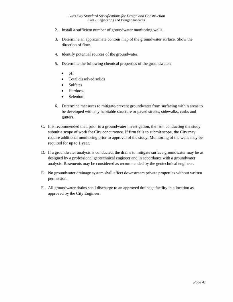
2. Install a sufficient number of groundwater monitoring wells.
3. Determine an approximate contour map of the groundwater surface. Show the direction of flow.
4. Identify potential sources of the groundwater.
5. Determine the following chemical properties of the groundwater:
• pH • Total dissolved solids • Sulfates • Hardness • Selenium
6. Determine measures to mitigate/prevent groundwater from surfacing within areas to be developed with any habitable structure or paved streets, sidewalks, curbs and gutters.
C. It is recommended that, prior to a groundwater investigation, the firm conducting the study submit a scope of work for City concurrence. If firm fails to submit scope, the City may require additional monitoring prior to approval of the study. Monitoring of the wells may be required for up to 1 year.
D. If a groundwater analysis is conducted, the drains to mitigate surface groundwater may be as designed by a professional geotechnical engineer and in accordance with a groundwater analysis. Basements may be considered as recommended by the geotechnical engineer.
E. No groundwater drainage system shall affect downstream private properties without written permission.
F. All groundwater drains shall discharge to an approved drainage facility in a location as approved by the City Engineer.

Ivins City Standard Specifications for Design and Construction Part 2 Engineering and Design Standards
Page 42
THIS PAGE IS INTENTIONALLY BLANK

Ivins City Standard Specifications for Design and Construction Part 2 Engineering and Design Standards
Page 43
2.3. STORM WATER DESIGN
2.3.1. GENERAL
All subdivisions and site developments shall be designed to accommodate rainfall in systems separate and independent from the sanitary sewer system. A flood control system shall be designed and approved as part of the construction plans. Flood water may be conveyed in approved drainage facilities which is defined to mean storm drain pipes, major washes, designated floodway easements, or dedicated city streets. Minor washes may also be considered approved drainage facilities if the discharge of storm water from a developed area does not exceed what the natural flow of the wash was prior to any development or if a dedicated drainage easement or its equivalent for the wash is provided.
2.3.2. STORM SYSTEM SIZING CRITERIA
The following criteria are used in determining and designing flood conveyance:
A. Storm water runoff from the 10-year storm will be conveyed by approved drainage facilities such that all collectors and arterials shall maintain at least two 12-foot drivable lanes. All residential streets shall maintain at least one 12-foot drivable lane. When underground systems are provided, all waters from the 10-year flood shall be contained within the system and not include over-ground flows as a portion of the capacity.
B. The 100-year storm will be conveyed within the limits of the street right-of-way or easements. All arterial streets must have a minimum 12-foot lane of travel.
C. Culverts and bridges should be sized as follows:
1. Arterial Streets – convey the 100-year flood.
2. Collectors – convey the 25-year flood.
3. All other streets – convey the 10-year flood.
D. Any exceptions must be approved by the City Engineer.
2.3.3. PRECIPITATION
A. All drainage studies shall use rainfall data published by the National Oceanic and Atmospheric Administration (NOAA) in the NOAA Atlas 14, Precipitation – Frequency Atlas of the Western United States, Volume 1, Version 4.0 or any modifications of such data by NOAA.
B. The Ivins City Storm Drain Capital Facilities Plan uses this data as listed for latitude 27.17 North, longitude 113.68 West, elevation 3162 feet, extracted from the NOAA Precipitation Frequency Data Server located at the following Internet web site:
http://hdsc.nws.noaa.gov/hdsc/pfds/sa/ut_pfds.html

Ivins City Standard Specifications for Design and Construction Part 2 Engineering and Design Standards
Page 44
Table 2.3.3 Point Precipitation Estimates from NOAA Atlas 14 for Ivins City
Utah 37.17N 113.68W 3162 feet
Precipitation Intensity Estimates (in/hr)
ARI (years) 5 min 10 min 15 min 30 min 60 min 120 min 3 hr 6 hr 12 hr 24 hr
10 3.48 2.65 2.19 1.47 0.91 0.52 0.37 0.22 0.13 0.08
25 4.49 3.41 2.82 1.9 1.18 0.65 0.46 0.27 0.16 0.09
100 6.35 4.83 3.99 2.69 1.66 0.9 0.61 0.36 0.2 0.11
Precipitation Frequency Estimates (inches)
10 0.29 0.44 0.55 0.74 0.91 1.04 1.11 1.32 1.56 1.92
25 0.37 0.57 0.71 0.95 1.18 1.30 1.38 1.62 1.92 2.16
100 0.53 0.81 1.00 1.35 1.66 1.80 1.83 2.16 2.40 2.64
C. Drainage studies should use these rainfall data unless there is sufficient justification otherwise.
2.3.4. STORM RUNOFF CALCULATIONS
A. The following storm distributions/methods are recommended for use:
1. Rational Method - recommended for small sites (less than 5 acres) and sizing individual inlets. Engineer may apply the 0.5 factor to the rational equation as recommended by the Clark County Hydrologic Criteria and Drainage Design Manual (1999, p611).
2. Farmer-Fletcher 3-hour Storm Distribution
3. SCS Type II compressed to a 6-hour Distribution
0
1
2
3
4
5
6
7
0 10 20 30 40 50 60 70
Intensity (in
/hr)
Duration (mInutes)
Intensity/Duration/Frequency Curves
10yr
25yr
100yr

Ivins City Standard Specifications for Design and Construction Part 2 Engineering and Design Standards
Page 45
4. SCS Type II 24-hour Storm Distribution
B. The rational method may be used with hand calculations, however, if the Farmer Fletcher or SCS Type II distribution is used then a computer application must be used applying either the SCS TR-55, SCS Unit Hydrograph or Kinematic Wave method. All computer input and output data should be provided in the drainage report. If a detention basin is being recommended, a storm distribution modeled through a computer application must be applied and a 3-hour, 6-hour and 24-hour storm shall be considered.
C. Time of Concentration (tc) may be calculated as per methods recommended by the Clark County Hydrologic Criteria and Drainage Design Manual or any method approved by St. George City. The value should be comparative to the tc values calculated in the Storm Drain Capital Facilities Plan.
D. When using SCS curve numbers, if the proposed conditions have a curve number that is lower or nearly equal to the existing conditions then it may be necessary to calculate the runoff solely from the estimated proposed impervious areas.
E. In a development where a fence or wall that would interrupt surface drainage is allowed but not installed with the development improvements, drainage must be designed as if such fencing were existing.
2.3.5. HYDRAULIC ANALYSIS
A. Any system with two or more inlets must be designed using hydraulic analysis software.
B. The EGL and HGL must be determined throughout the reaches of the pipe and must be shown on the construction drawings.
2.3.6. STREETS
A. Streets may be used as the primary storm drainage system in many subdivisions and site developments. Streets must be shown to adequately handle the variety of storms per the storm system sizing criteria given above.
B. All subdivisions and site development should indicate the carrying capacity of the street using the Manning’s equation.
C. Highback curbs (versus modified curbs) may be required in locations where streets are on a grade 2% or steeper with a curvilinear shape.
2.3.7. MANHOLES
A. Manholes shall be provided for maintenance purposes at a maximum horizontal distance of 500 feet.
B. Cleanouts are not allowed in lieu of manholes.
C. Required at all changes in pipe size, horizontal alignment, or vertical alignment.

Ivins City Standard Specifications for Design and Construction Part 2 Engineering and Design Standards
Page 46
2.3.8. DROP INLETS
A. Combination curb opening/grate inlet type shall generally be used in any urban street unless otherwise approved.
B. A drop inlet shall be used to collect storm water in lieu of a cross gutter whenever located within 300 feet of an underground storm drainage system.
C. Inlets must be considered with 50% blockage.
D. Engineer shall verify inlet capacity following methodology in the Clark County Hydrologic Criteria and Drainage Design Manual (1999, p818)
2.3.9. STORM DRAIN PIPELINES
A. Located within a dedicated right-of-way, drainage easement or equivalent.
B. Pipelines shall be designed to convey entire flood as per sizing criteria given above with no surface flooding following any inlets.
C. Minimum pipe diameter is 12 inches when slopes are 1.5% or greater, 15 inches when slopes are less than 1.5%.
D. Minimum pipe cover is 12-inches. If less than 24-inches must use reinforced concrete pipe with Class I backfill only. Less than 12-inches cover may be allowed with concrete encasement.
E. Pipelines must be installed straight between manholes/inlets. Curvilinear pipes may be considered if pipe is running parallel to a curvilinear road.
F. Approved pipe materials:

Ivins City Standard Specifications for Design and Construction Part 2 Engineering and Design Standards
Page 47
Table 2.3.8 Approved Storm Drain Pipe Materials
Type Ref Std.
Common Brand Name*
Design Manning's
n
Pipe Stiffness (psi)
Min Burial Depth (ft)
Max Burial Depth (ft)
Backfill Material Class
Allowed Pipe
Diameters (in) Notes
Reinforced Concrete
ASTM C76
0.013 Rigid 1 30** I, II, III, IV
12" to 96"
Non Reinforced Concrete
ASTM C14
0.013 Rigid 2 17** I, II, III, IV
12" to 30"
Corrugated HDPE
ASTM F2648
ADS N‐12 0.013 50 to 42 2 10** I,II 12" & 15" Larger diameters may be allowable with flowable fill in the pipe zone.
Corrugated Polypropylene
ASTM F2736 & F2764
ADS N‐12 HP
0.013 75 to 46 2 17** I,II 12" to 30" Larger diameters may be allowable with flowable fill in the pipe zone.
Corrugated PVC
ASTM F949 & F794
Contech A‐2000
0.013 46 2 17** I,II 12" to 30" Larger diameters may be allowable with flowable fill in the pipe zone.
*provided for reference only, other equal brands may be used upon approval. ** Greater depths may be allowed with prior written approval by City Engineer.
2.3.10. CULVERTS
A. The minimum culvert size is 18 inches in diameter.
B. The engineer shall consider a blockage factor of 50 percent for all culverts conveying storm drainage from undeveloped areas as determined by the City.
C. Trash racks shall be used where the City determines that there is a high risk of severe blockages.
2.3.11. HEADWALLS
A. For any culvert entrance or exit a head wall and concrete apron shall be required to control erosion
B. Headwall shall be reinforced concrete if culvert material is any type of plastic.
C. Stacked rock with a concrete apron may be used for concrete pipe culverts.
D. A railing may be required if the City determines there is a risk to pedestrians or bicyclists.
2.3.12. BRIDGES
A. A minimum of 2 feet of freeboard shall be provided.

Ivins City Standard Specifications for Design and Construction Part 2 Engineering and Design Standards
Page 48
B. Local and regional scour analysis are required on the structure, upstream and downstream and embankments. All potential scour will be mitigated.
2.3.13. OPEN CHANNELS
A. Located within a dedicated right-of-way, drainage easement or equivalent.
B. Convey the 100-year flood event with a minimum freeboard of 1 foot.
C. Line with rock or other similar erosion control if velocities are expected to exceed 2 feet per second.
D. No side-slopes steeper than 2H:1V.
2.3.14. DETENTION/RETENTION
A. Required when:
1. Downstream conveyance facilities are considered to be at full capacity.
2. Discharging to private property without a drainage easement unless discharge does not exceed that which existed prior to development, nor does it concentrate.
B. Minimum of 1 foot freeboard.
C. Maximum of 4H:1V side-slope.
D. Provide monitoring and maintenance plan.
E. Provide vehicular access.
F. Provide emergency spillway sized with the assumption that outlet is closed in 10-year event or 50% clogged in 100-year event.
G. All detention facilities shall be landscaped.
H. No reduction of size shall be made for evaporation or infiltration.
I. Maximum depth of 3 feet unless otherwise approved.
J. Outlet shall have a minimum discharge area of 6 square inches.
K. Retention basins:
1. Only allowed in extreme situations with written approval by City.
2. Percolation test must show that the capability of draining within 48 hours of storm event.

Ivins City Standard Specifications for Design and Construction Part 2 Engineering and Design Standards
Page 49
3. When located within 25 feet of adjacent property or structure, must be certified by geotechnical engineer to have no impact on the foundation stability strength of the soil underlying the adjacent property or structure.
4. Provide detailed maintenance plan.
2.3.15. FLOOD PLAINS
Any development occurring within a flood plan shall comply with the City’s Flood Damage Prevention ordinance located in Ivins City Code, Title 7, Chapter 11.
2.3.16. POST-CONSTRUCTION POLLUTION PREVENTION
A. Storm water treatment for oil and grease are required on all sites with more than 6 parking spaces.
B. Provide a maintenance plan for the storm water treatment facility.
C. Erosion/sediment basins are required on developed sites that have the potential to produce more erosion than the natural desert environment as determined by the City.
2.3.17. DRAINAGE REPORTS
A. A preliminary drainage report shall be provided at preliminary plan for subdivisions.
B. A final drainage report shall be provided prior to any review of construction drawings for a subdivision or site development.
C. The drainage report shall contain all the information as provided in the drainage report checklist attached to these specifications in Appendix H. All reports shall be submitted with this checklist attached.
2.3.18. PRIVATE DRAINAGE SYSTEMS
A. Private systems not maintained by Ivins City must meet these above requirements except as follows:
1. Approved pipe and inlet materials do not apply.
2. Smaller pipe sizes may be used for systems draining roofs, landscape areas, or any area that is not considered common area nor used for public access and parking.
3. Cleanouts may be used in lieu of manholes.

Ivins City Standard Specifications for Design and Construction Part 2 Engineering and Design Standards
Page 50
THIS PAGE IS INTENTIONALLY BLANK

Ivins City Standard Specifications for Design and Construction Part 2 Engineering and Design Standards
Page 51
2.4. GRADING
All grading of site developments and subdivisions shall comply with the grading requirements of this section, Zoning Ordinance (16.11.134), Subdivision Ordinance (15.05.102), and Appendix J of the International Building Code (IBC) which has been adopted to be applicable to Ivins City.
2.4.1. STREETS
A. Streets should be designed to match natural grade as much as practical within design requirements. Any fills greater than 1 foot, measured at the street centerline, except for the crossing of washes and significant depressions may be determined by the City Engineer to be excessive.
B. When the design centerline of new streets exceed 2% grade, the streets shall be tabled across intersections at a grade that does not exceed 2% for the consideration of ADA compliant crosswalks.
2.4.2. CUTS/FILLS
A. Any cut or fill greater than 4 feet within 10 feet of a property line is generally prohibited without the approval of the adjacent property owner.
B. Filling in a drainage may be acceptable if the drainage report shows the drainage is no longer necessary.
C. Imported fills shall meet requirements of the geotechnical report.
D. Fills over the top of existing slopes steeper than 5H:1V shall be benched in accordance with IBC Appendix J.
2.4.3. SLOPES
A. Maximum slope of an embankment is 2H:1V except as allowed by the IBC Appendix J.
B. Cut and fill slopes shall be set back from the property lines in accordance with IBC Appendix J.
2.4.4. SUBDIVISION LOTS
A. If the pad elevations for two adjacent 11,000 square foot or smaller lots vary more than two feet, a retaining wall shall be required.
B. It is recommended that subdivisions with lots greater than 11,000 square feet be left with natural vegetation ungraded.
C. All lots graded flat shall be reseeded or be designed to retain water in a 1.5-inch storm event assuming no infiltration or evaporation during the storm.
Ivins City Standard Specifications for Design and Construction Part 2 Engineering and Design Standards
Page 52
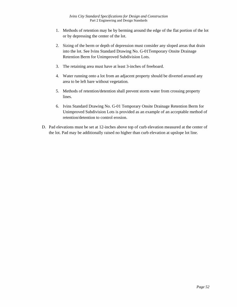
1. Methods of retention may be by berming around the edge of the flat portion of the lot or by depressing the center of the lot.
2. Sizing of the berm or depth of depression must consider any sloped areas that drain into the lot. See Ivins Standard Drawing No. G-01Temporary Onsite Drainage Retention Berm for Unimproved Subdivision Lots.
3. The retaining area must have at least 3-inches of freeboard.
4. Water running onto a lot from an adjacent property should be diverted around any area to be left bare without vegetation.
5. Methods of retention/detention shall prevent storm water from crossing property lines.
6. Ivins Standard Drawing No. G-01 Temporary Onsite Drainage Retention Berm for Unimproved Subdivision Lots is provided as an example of an acceptable method of retention/detention to control erosion.
D. Pad elevations must be set at 12-inches above top of curb elevation measured at the center of the lot. Pad may be additionally raised no higher than curb elevation at upslope lot line.

Ivins City Standard Specifications for Design and Construction Part 2 Engineering and Design Standards
Page 53
2.5. EROSION CONTROL
2.5.1. GENERAL
A. Necessary measures shall be taken to prevent erosion due to drainage at all points in new developments.
B. During grading and construction, the developer shall control all potential storm runoff so that eroded soil and debris cannot enter any downstream water course or adjoining property.
C. All drainage that leaves a new development shall be adequately addressed to mitigate all erosion on adjacent properties.
D. Erosion mitigation shall be permanent unless otherwise approved.
2.5.2. UPDES PERMIT
A. All new construction that disturbs one acre of land or more shall obtain a UPDES Storm Water General Permit for Construction Activities (Permit #UTR300000) before construction begins.
B. The permit requires the operator, typically the contractor, to control and eliminate storm water pollution sources through the development and implementation of a Storm Water Pollution Prevention Plan (SWPPP).
C. The permit also requires inspection of the BMP controls either:
1. At least once every 7 calendar days, or
2. At least once every 14 days and within 24 hours of the end of a storm event of 0.5 inch or greater.
2.5.3. SWPPP
A. The Storm Water Pollution Prevention Plan (SWPPP) shall be prepared and submitted to the City for review before the contractor can obtain the UPDES permit.
B. Section 3.5 of the UPDES Permit No. UTR300000 describes in detail what shall be included in the SWPPP.
C. The plan shall include, among other things:
1. Possible sources of storm water pollutants
2. Selection of Best Management Practices (BMPs) to reduce or eliminate pollutant impacts.
D. A SWPPP template that addresses all of the information required in the SWPPP can be obtained from the State of Utah Division of Water Quality web site:

Ivins City Standard Specifications for Design and Construction Part 2 Engineering and Design Standards
Page 54
http://www.waterquality.utah.gov/UPDES/stormwatercon.htm.
2.5.4. PERMITTING PROCESS
A. The Operator prepares a SWPPP in accordance with the UPDES Permit.
B. The Operator Submits SWPPP to City for review.
C. Once the City has reviewed the SWPPP, the operator applies for the UPDES Permit by completing the Notice of Intent (NOI) form. The form can be completed online at: https://secure.utah.gov/stormwater/main.html
D. Construction may commence only after:
1. The SWPPP has been reviewed by the City
2. The NOI has been submitted
3. The Operator has attended a pre-construction meeting with designated City personnel to review and discuss the SWPPP, and
4. All other applicable permits have been obtained from the City.
E. Once construction has been completed and the site stabilized, the contractor shall complete the Notice of Termination (NOT) form and submit to the Division of Water Quality.

Ivins City Standard Specifications for Design and Construction Part 2 Engineering and Design Standards
Page 55
2.6. STREET DESIGN
2.6.1. GENERAL DESIGN STANDARDS
A. Streets shall conform to the following design standards:
Table 2.6.1 General Street Design Standards
Road Classification
Right-of-Way
Width (ft)
Maximum Grade
(%)
Pavement Width (ft)
Minimum Half
Street Asphalt
Width (ft)
Design Speed
(mph) 1
Centerline Minimum Curvature
Radius (ft) 1
Sidewalk Minimum
Width (ft)4
Curb Return Radius
(ft) 2
Residential Standard 50'
50 12%5 28 26 25 100 5 3 20
Residential Alternative 43'
43 12%5 28 26 25 100 5 3 20
Residential Alternative 38'
38 12%5 28 26 25 100 5 3
(one side) 20
Residential Private Rural
38 12%5 26 26 15 70 5 3 15
Residential Collector
55 12%5 32 26 25 200 5 25
Minor Collector
60 8% 32 26 30 200 5 25
Major Collector
66 8% 42 30 35 400 5 30
Minor Arterial - Center Street
85 8% 60 35 45 700 6 35
Minor Arterial - Western Corridor
90 8% 64 45 45 700 6 35
Major Arterial - Old Highway 91 (3-lanes)
100 8% 50 50 55 1000 6 [or 10' trail]
40
1. Private Residential Roads may use lower design speeds and centerline curve radii. 2. Curb Return Radius shall use the largest street type found at the intersection. 3. See Transportation Master Plan for additional information. 4. Sidewalks in areas of high pedestrian traffic may require greater width. 5. See Ivins City Zoning Ordinance
B. Streets shall be designed to provide adequate stopping and sight distance, degree of curve, and superelevation in accordance to standard engineering practice.
C. Subdivisions and other developments shall be designed to provide future access to adjoining vacant parcels
1. Developments shall also be designed so that existing stub streets in existing developments will be connected to the proposed streets and accesses.

Ivins City Standard Specifications for Design and Construction Part 2 Engineering and Design Standards
Page 56
2. Where a stub street is provided which accesses more than 2 lots on each side, a temporary turnaround and public use easement at least 80 feet in diameter shall be provided.
3. The city may require improvements to be installed in temporary turnaround areas.
D. Streets in subdivisions, excluding collector streets, exceeding 80 feet in length are encouraged to be curvilinear or provide sufficient alignment variation to calm traffic and enhance aesthetic appeal in the subdivision.
E. Cul-de-sac streets may not exceed 600 feet in length as measured from the center of the intersection of a connecting through street to the center of the turnaround area.
1. The maximum length of a cul-de-sac street may not be extended by additional turnarounds between the intersecting through street and the cul-de-sac.
2. If the distance from the end of a proposed cul-de-sac to a connecting road is less than 1/3rd the length of the proposed cul-de-sac street, connection to the connecting road shall be required if doing so does not violate requirements of the Ivins City transportation master plan, does not disturb or eliminate any unique geographical feature, and does not prevent full development of approved densities.
2.6.2. CROSS SECTIONS
A. Cross-sections are as approved by the Transportation Master Plan which are attached to this document in Appendix H for reference.
B. All asphalt edges for half street sections shall abut concrete or a 2-foot aggregate base shoulder.
2.6.3. ROAD NETWORKS
A. All streets in a development shall conform to the Ivins City Transportation Master Plan.
B. Curvilinear streets are encouraged to reduce, or eliminate long straight stretches of residential roadways.
C. Streets and accesses to streets should be completed in accordance with the access management standards provided in the Transportation Master Plan.
2.6.4. TECHNICAL DESIGN REQUIREMENTS
A. Street grades:
1. All street grades shall have a maximum grade as shown in Table 2.6.1.
2. A request to increase the maximum street grades shown in Table 2.6.1 may be considered upon submittal of a request and information justifying such a request to the City Engineer. Request for approval must be based upon and in accordance with

Ivins City Standard Specifications for Design and Construction Part 2 Engineering and Design Standards
Page 57
the latest edition of AASHTO's “A Policy on Geometric Design of Highways and Streets” guidelines. Any approvals for increased grades must be consistent with access requirements of fire apparatus as defined by the Fire Department. The City Engineer’s decision will be final. Cost of construction will not be justification for approval.
B. Intersections:
1. Street intersections shall be as near to 90 degrees as possible.
2. Up to 15 degree skew angle may be allowed on a case by case basis if no other reasonable option exists.
3. Street intersection centerline offsets shall be not less than 150 feet.
4. Intersections should be sloped at an angle no greater than 2 percent to accommodate pedestrian crossings. It may be necessary to “table” an intersection in new construction areas.
5. Proper combination of horizontal and vertical alignment should be obtained by engineering study and consideration of the general guidelines listed in AASHTO (Section Titled: Combination of Horizontal and Vertical Alignment, 1990 edition).
6. Intersections should not be located on the interior of, or near, sharp curves. Intersections should be located a sufficient distance from all curves to provide proper sight distance for vehicles on the intersecting road or driveway and on the through road.
7. New intersections with more than four “legs” are generally not permitted.
8. When designing local road networks, “T” and “L” intersections are desired. Four-leg intersections on local road networks are generally discouraged. A development must obtain approval from City Engineer prior to design of the road network.
9. When designing local road networks, block lengths without an intervening connector street shall not exceed eight hundred feet (800') in length unless previous approval has been obtained from the City Engineer. Cul-de-sacs are not considered an intervening connecting street.
10. Accesses must be in accordance with the Access Management as provided in Section 2.7.1.
11. The intersection of two local roads should be designed to operate with minimal traffic control devices. For example, do not design an intersection to operate with a four-way stop or signal control.
12. Direct access will not be allowed for parking, loading or driveway areas that require backing maneuvers onto major collector or higher order streets. This requirement

Ivins City Standard Specifications for Design and Construction Part 2 Engineering and Design Standards
Page 58
shall apply to commercial and industrial use regardless of the order or classification of street.
13. Residential and commercial developments are generally required to provide at least two improved accesses to the development depending upon the forecasted traffic volumes and number of homes and lots.
2.6.5. CURB SIDE MAILBOXES
A. All roadside mail boxes should be installed in accordance with applicable postal standards in the following locations:
1. In areas where the sidewalk is next to the curb, install boxes behind the sidewalk so as to not encroach into the sidewalk;
2. In areas where a planter strip is provided, mail boxes may be installed within the strip, provided no part extends into the sidewalk or beyond the back of the curb;
3. In rural areas where no barrier curb is installed, a minimum clear zone of 10 feet from the traveled way should be provided.
B. All mailboxes shall be handicap accessible.
2.6.6. SIGNS AND PAVEMENT MARKINGS
A. All street name and traffic control signs and pavement markings required on the street system within a development or as a result of the development, shall be installed at the developer's expense in accordance with the standard drawings and MUTCD standards.
B. A signing plan should be submitted with the engineering drawings, however, additional signing and traffic control may be added to the project as determined by the City’s Representative.
2.6.7. PAVEMENT
A. All streets, public or private, shall be surfaced to grade, with asphalt concrete pavement, to the required minimum width and thickness in accordance with these specifications.
B. All streets require a fog seal coat to be installed no sooner than 6 months after completion yet prior to release of the warranty bond.
2.6.8. CURB AND GUTTER
A. All public or private streets shall use curb and gutter of the type shown in standard cross-sections unless otherwise approved by the City Engineer.
B. No curb shall be cut for the installation of a driveway without the installation of a concrete apron in accordance with standard details.

Ivins City Standard Specifications for Design and Construction Part 2 Engineering and Design Standards
Page 59
2.6.9. TRANSITIONS/TAPERS
A. All streets shall transition with tapers set at a ratio of no less than 12:1.
B. The transition taper area may be installed as a temporary asphalt section with no less than 2 inches of asphalt over 6 inches of roadbase.
2.6.10. CROSS-GUTTERS
A. No cross gutters shall be allowed across major collector or major and minor arterial streets.
B. On commercial and industrial streets, cross gutters are generally not allowed and require approval by the City Engineer for their use.
C. The City Engineer may prohibit construction of cross gutters on any street deemed necessary.
2.6.11. SIDEWALKS
A. Widths shall be in accordance with Table 2.6.1.
B. A maximum grade of 5%, or 2% greater than the existing/proposed street grade, whichever is less, shall be required as measured along the running length of a meandering sidewalk.
C. If the existing/proposed street grade is greater than 5%, then a meandering sidewalk shall not be permitted.
D. Whenever any sidewalk connects with any trails, paths and/or other sidewalks that are larger or smaller in width, a transitional area will be required for design and safety standards.
E. Sidewalk and bike paths shall be meandering on streets 66 feet wide or wider.
F. Meandering sidewalks shall be carefully laid out on the construction plans as follows:
1. Distance between inflection points of meander shall be typically spaced 200 to 300 feet.
2. In no case shall the distance be less than 100 feet unless necessary to avoid an obstacle as approved by the City.
3. Meander should not curve at a radius less than 200 feet unless nessessary to avoid an obstacle as approved by City.
G. Additional easements may be required for the placement of serpentine sidewalks along the rights-of-way.
H. All pedestrian accesses shall conform to ADA standards.

Ivins City Standard Specifications for Design and Construction Part 2 Engineering and Design Standards
Page 60
2.6.12. CONCRETE COLOR
A. If the developer chooses to color required curb, gutter, and sidewalks, the color shall be either Davis 160-Sunset Rose, or Davis 641-Yosemite Brown.
2.6.13. PLANTER STRIPS
A. Must be landscaped with at least 50%, by area of matured plant, of live vegetation.
B. Shall not be filled with any impervious material.
C. Shall be sloped at a minimum of 2% and a maximum of 12%.
2.6.14. ASPHALT TRAILS /PATHS
A. Shared use trails shall be installed in accordance with the Transportation Master Plan.
B. Provide a 10-foot wide trail with 2.5-inches of asphalt over 4-inches of roadbase.
C. Meandering trails should comply with the meandering requirements of sidewalks.
Ivins City Standard Specifications for Design and Construction Part 2 Engineering and Design Standards
Page 61
2.7. TRAFFIC
2.7.1. ACCESS MANAGEMENT
A. Corner Spacing
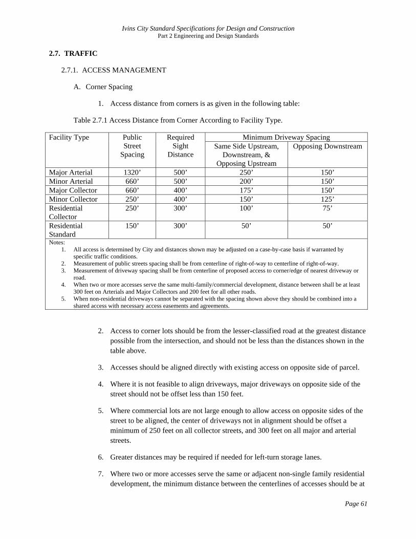
1. Access distance from corners is as given in the following table:
Table 2.7.1 Access Distance from Corner According to Facility Type.
Facility Type Public Street
Spacing
Required Sight
Distance
Minimum Driveway Spacing Same Side Upstream,
Downstream, & Opposing Upstream
Opposing Downstream
Major Arterial 1320’ 500’ 250’ 150’ Minor Arterial 660’ 500’ 200’ 150’ Major Collector 660’ 400’ 175’ 150’ Minor Collector 250’ 400’ 150’ 125’ Residential Collector
250’ 300’ 100’ 75’
Residential Standard
150’ 300’ 50’ 50’
Notes: 1. All access is determined by City and distances shown may be adjusted on a case-by-case basis if warranted by
specific traffic conditions. 2. Measurement of public streets spacing shall be from centerline of right-of-way to centerline of right-of-way. 3. Measurement of driveway spacing shall be from centerline of proposed access to corner/edge of nearest driveway or
road. 4. When two or more accesses serve the same multi-family/commercial development, distance between shall be at least
300 feet on Arterials and Major Collectors and 200 feet for all other roads. 5. When non-residential driveways cannot be separated with the spacing shown above they should be combined into a
shared access with necessary access easements and agreements.
2. Access to corner lots should be from the lesser-classified road at the greatest distance possible from the intersection, and should not be less than the distances shown in the table above.
3. Accesses should be aligned directly with existing access on opposite side of parcel.
4. Where it is not feasible to align driveways, major driveways on opposite side of the street should not be offset less than 150 feet.
5. Where commercial lots are not large enough to allow access on opposite sides of the street to be aligned, the center of driveways not in alignment should be offset a minimum of 250 feet on all collector streets, and 300 feet on all major and arterial streets.
6. Greater distances may be required if needed for left-turn storage lanes.
7. Where two or more accesses serve the same or adjacent non-single family residential development, the minimum distance between the centerlines of accesses should be at

Ivins City Standard Specifications for Design and Construction Part 2 Engineering and Design Standards
Page 62
least 200 feet on streets with design speeds below 30 mph and 300 feet on streets with design speeds above 30 mph.
8. If adjacent driveways cannot be separated by the distances outlined, they should be combined into a single joint access.
9. At least 300 feet of clear sight distance shall be provided for drivers entering or leaving all accesses onto local streets; 400 feet for collector streets; and 500 feet for arterial streets.
B. Number of accesses per parcel:
1. Accesses may be limited to one per commercial or multifamily residential development.
2. Additional accesses may be approved by the City upon completion of a circulation plan or Traffic Impact Study provided to the City indicating that more than one access is required to adequately handle the developments traffic volumes and further indicating that the additional access will not be detrimental to traffic flow on the adjacent street network or to meet emergency access requirements.
3. Number of accesses shall not exceed two for frontage of 300 feet or less, three for 300 to 600 feet of frontage and a maximum of three accesses for frontage greater than 600 feet, as approved by the City.
4. Where multiple parcels are consolidated, accesses shall also be consolidated according to City design and spacing standards.
5. Temporary access may be granted to undeveloped property prior to completion of a final development plan if access is needed for construction or preliminary site access. Temporary accesses are subject to removal, relocation, or redesign after final development plan approval.
6. Shared access between adjacent parcels shall be required where possible.
C. Single Family Residential Access:
1. New single family residential developments and subdivisions shall not have driveway access on arterials and major collectors.
2. Minor subdivisions or “flag lots” are discouraged along arterials and major collectors.
3. Accesses for these minor subdivisions are under the same criteria for design and spacing listed in the table above.
4. When two or more accesses serve adjacent single-family residential property, the minimum distance between the nearest points of the two accesses shall be at least 12 feet.

Ivins City Standard Specifications for Design and Construction Part 2 Engineering and Design Standards
Page 63
5. For corner residential lots, one access on each frontage may be permitted if it is determined by the City that two driveways are needed to provide safe access for traffic entering and leaving the lot because of site distance and geometric design considerations.
6. Double frontage residential lots will only have one access onto the lesser classified roadway unless approved by the City.
7. Circular driveways are considered one access.
8. If a lot has a circular driveway then only a maximum of one more additional access may be granted.
9. Single-family residential driveways shall have a maximum curb cut of 40 feet.
10. Circular driveways should have a maximum curb cut of 20 feet per side.
D. Right-turn Deceleration lanes:
1. Minimum requirements for installation of a right-turn lane on a rural two-lane road that is 40 mph or less is 50 vehicles per hour (vph).
2. For greater than 40 mph, right-turn traffic of 25 vph or more would require a right-turn deceleration lane.
3. Taper lengths and storage lengths of these lanes shall comply with AASHTO’s Policy on Geometric Design of Highways and Streets.
E. Based upon safety and operational studies, median treatments such as Two-Way-Left-Turn Lanes (TWLTL) and Raised non-Transferable medians may be required on major collector and arterial streets, as determined by the City and the Transportation Master Plan.
F. New access locations created by development shall be unified whenever possible to create the fewest number of access points onto arterials or major collectors. Joint use agreements shall be required where necessary.
2.7.2. TRAFFIC IMPACT STUDIES
A. Development conditions which trigger Traffic Impact Study (TIS) requirement:
1. TIS is required if development will generate new peak hour trips (as determined by the latest edition of ITE Trip Generation Manual) during the morning, afternoon, or Saturday peak hour as follows:

Ivins City Standard Specifications for Design and Construction Part 2 Engineering and Design Standards
Page 64
Category
Peak Hour Trips Generated by Development
I 100 to 500 II 500 to 1,000 III More than 1,000
2. Category I TIS may also be required by the City for any specific traffic problems or concerns such as:
• Proposed or existing offset intersections. • Situation with a high number of traffic accidents. • Driveway conflicts with adjacent developments. • Nearby intersections that have reached their capacity. • Proposed property rezones when there is a significant potential increase in traffic
volumes. • When the original TIS is more than two years old, or where the proposed traffic
volumes in the original TIS increase by more than twenty percent.
B. Scope of each TIS category is as follows:
TIS Period Evaluations Scope of Study
Category Ope
ning
Yea
r of D
evel
opm
ent
Yea
r of C
ompl
etio
n of
Eac
h Ph
ase
Com
plet
ion
of D
evel
opm
ent
Five
Yea
rs a
fter t
he
deve
lopm
ent’s
com
plet
ion
10 y
ears
afte
r the
dev
elop
men
ts
com
plet
ion
Site
Acc
ess D
rives
Aff
ecte
d Si
gnal
ized
In
ters
ectio
ns
Aff
ecte
d m
ajor
uns
igna
lized
st
reet
inte
rsec
tions
Sign
aliz
ed In
ters
ectio
ns w
ithin
1/
2 m
ile
Uns
igna
lized
maj
or st
reet
in
ters
ectio
ns w
ithin
1/2
mile
I x x x x x II x x x x x x x x x III x x x x x x x x x x
C. Initial TIS determination process:
1. Developer, or their agent, estimates number of trips
2. City provides concurrence or modifies estimate. City makes recommendation on category of TIS.

Ivins City Standard Specifications for Design and Construction Part 2 Engineering and Design Standards
Page 65
3. Developer, or their agent, submits a draft table of contents for the TIS, a map of intersections to be analyzed, and a draft of the proposed trip distribution for site traffic.
4. City provides concurrence or recommends modifications to the submittal. Upon approval, actual TIS work may begin.
D. Analysis and Approach Methods:
1. TIS must be conducted and prepared under the direction of a Professional Engineer, licensed in the State of Utah.
2. The extent of the study area may be either enlarged or decreased, depending on special conditions as determined by the City.
3. Both the morning and afternoon weekday peak hours should be analyzed, unless the proposed project is expected to generate no trips, or a very low number of trips, during either the morning or evening peak periods. If this is the case, the requirement to analyze one or both of these periods may be waived by the City.
4. Where the peak traffic hour in the study area occurs during a different time period than the normal morning or afternoon peak travel periods (for example mid-day), or occurs on a weekend, or if the proposed project has unusual peaking characteristics, these additional peak hours should also be analyzed.
5. When directed by the City, traffic volumes for the analysis hours should be adjusted for the peak season, in cases where seasonal traffic data is available.
E. All data should be collected in accordance with the latest edition of the ITE Manual of Traffic Engineering Studies:
1. Turning Movement Counts: Manual turning movement counts should be obtained for all existing cross-street intersections to be analyzed during the morning, afternoon and Saturday peak periods (as applicable). Turning movement counts may be required during other periods as directed by the City. Turning movement counts may be extrapolated from existing turning movement counts, no more than two years old, with the concurrence of the City.
2. Daily Traffic Volumes: The current and projected daily traffic volumes should be presented in the report. If available, daily count data from the local agencies may be extrapolated to a maximum of two years with the concurrence of the City. Where daily count data is not available, mechanical counts will be required at locations agreed upon by the City.
3. Roadway and Intersection Geometrics: Roadway geometric information should be obtained. This includes, but is not limited to, roadway width, number of lanes, turning lanes, vertical grade, location of nearby driveways, and lane configuration at intersections.

Ivins City Standard Specifications for Design and Construction Part 2 Engineering and Design Standards
Page 66
4. Traffic Control Devices: The location and type of traffic controls should be identified at all locations to be analyzed.
F. Trip Generation:
1. The latest edition of ITE's Trip Generation Manual should be used for selecting trip generation rates. Other rates may be used with the approval of the City in cases where Trip Generation does not include trip rates for a specific land use category, or includes only limited data, or where local trip rates have been shown to differ from the ITE rates.
2. Site traffic should be generated for daily, AM, PM and Saturday peak hour periods (as applicable).
3. Adjustments made for "pass-by", “diverted-link” or "mixed-use" traffic volumes shall follow the methodology outlined in the latest edition of the ITE Trip Generation Manual or the ITE Trip Generation Handbook.
4. A "pass-by" traffic volume discount for commercial centers should not exceed twenty-five percent unless approved by the City.
5. A trip generation table should be prepared by phase showing proposed land use, trip rates, and vehicle trips for daily and peak hour periods and appropriate traffic volume adjustments, if applicable.
G. Trip Distribution and Assignment:
1. Projected trips should be distributed and added to the projected non-site traffic on the roadways and intersection under study.
2. The specific assumptions and data sources used in deriving trip distribution and assignment should be documented in the report and reviewed with the City.
3. Future traffic volumes should be estimated using information from transportation models, or applying an annual growth rate to the base-line traffic volumes.
4. The future traffic volumes should be representative of the horizon year for project development.
5. If the annual growth rate method is used, the City must give prior approval to the growth rate used. In addition, any nearby proposed development projects currently under review by the City (“on-line”) should be taken into consideration when forecasting future traffic volumes. The increase in traffic from proposed "on-line" projects should be compared to the increase in traffic by applying an annual growth rate.
6. If modeling information is unavailable, the greatest traffic increase from either the "on-line” developments, the application of an annual growth rate or a combination of

Ivins City Standard Specifications for Design and Construction Part 2 Engineering and Design Standards
Page 67
an annual growth rate and "on-line" developments, should be used to forecast the future traffic volumes.
7. The site-generated traffic should be assigned to the street network in the study area based on the approved trip distribution percentages. The site traffic should be combined with the forecasted traffic volumes to show the total traffic conditions estimated at development completion.
8. A "figure" should be prepared to represent the site specific traffic impacts to existing conditions: It must show:
• Daily and peak period turning movement volumes for each traffic study intesection.
• Existing base-line volumes of the street network. • Volumes of the street network with the site generated traffic added.
H. Capacity Analysis
1. Level of service (LOS) shall be computed for signalized and unsignalized intersections in accordance with the latest edition of the Highway Capacity Manual.
2. The intersection LOS should be calculated for each of the following conditions (if applicable):
• Existing peak hour traffic volumes (“figure” required). • Existing peak hour traffic volumes including site-generated traffic (“figure”
required). • Future traffic volumes not including site traffic (“figure” required). • Future traffic volumes including site traffic (“figure” required). • LOS results for each traffic volume scenario (“table” required).
3. The LOS table should include LOS results for AM, PM and Saturday peak periods, if applicable.
4. The table shall show LOS conditions with corresponding vehicle delays for signalized intersections, and LOS conditions for the critical movements at unsignalized intersections.
5. For signalized intersections, the LOS conditions and average vehicle delay shall be provided for each approach and the intersection as a whole.
6. The incremental increases in site traffic from each phase, where applicable, should be included in the LOS analysis for each preceding year of development completion.
7. A “figure” will be required for each horizon year of phased development.

Ivins City Standard Specifications for Design and Construction Part 2 Engineering and Design Standards
Page 68
I. Traffic Signal and Roundabout Studies
1. An intersection needs study should be conducted for all new proposed roundabouts and/or traffic signals for the base year. If the warrants are not met for the base year, they should be evaluated for each year in the five-year horizon. Traffic signal and roundabout needs studies should be conducted by a method pre-approved by the City.
2. Speed Considerations: Vehicle speed is used to estimate safe stopping and cross corner sight distances. In general, the posted speed limit represents the 85th percentile speed. The design speed of the roadway should be used to calculate safe stopping and cross corner sight distances.
3. Improvement Analysis: The roadways and intersections within the study area should be analyzed, with and without the proposed development to identify any projected impacts in regard to LOS and safety.
4. Where the highway will operate at LOS C or better without the development, the traffic impact of the development on the roadways and intersections within the study area should be mitigated to LOS D for arterial and collector streets and LOS C on all other streets during peak hours of travel. Mitigation to LOS D on other streets may be acceptable with the concurrence of the City.
J. TIS report format shall conform to the format given in Appendix J. Deviations from this format must receive prior approval of the City

Ivins City Standard Specifications for Design and Construction Part 2 Engineering and Design Standards
Page 69
2.8. SANITARY SEWER DESIGN
2.8.1. DESIGN FLOWS
A. All sanitary sewers and appurtenances shall be designed to carry the design flows from all contiguous areas which may, within a reasonable period of time, be tributary thereto.
B. Sanitary sewers shall be designed to carry the peak discharge as specified below:
1. Laterals and collector mains: 400 gallons/capita/day
2. Interceptor and outfall mains: 250 gallons/capita/day
C. Other flow rates supported by accepted engineering practice may be submitted for review by City Engineer.
D. Minimum manning’s “n” value is 0.012.
2.8.2. MINIMUM SLOPES
A. The following shall be the minimum slopes to be provided, unless approved otherwise by the City:
SEWER PIPE DIAMETER (inches)
MINIMUM SLOPE (%)
4 2.00 6 1.00 8 0.50
10 0.40 12 0.35 15 0.30 18 0.25 21 0.20
24 and greater 0.15
B. Any deviation from these minimum slopes will require a justification with calculations from a licensed engineer showing that a 2 foot per second velocity can be maintained even in a low flow condition.
C. Where design velocities are projected to be greater than 15 feet per second, the sewers and manholes shall be protected against displacement by erosion and impact
2.8.3. MINIMUM SIZE AND DEPTH
A. Minimum pipe diameter for a sewer main is 8 inches.
B. Sanitary sewers shall be designed of sufficient depth to permit sewer laterals from basements to be connected. Exceptions may be granted in subdivisions or areas in which no basements are to be constructed. A note shall be made on the plat to prohibit basements in these areas.
Ivins City Standard Specifications for Design and Construction Part 2 Engineering and Design Standards
Page 70
C. Sewer shall be installed at a depth at least 18-inches below bottom of waterline wherever possible.
D. Minimum depth of a sewer main, to top of pipe, will be not less than 36" below subgrade of roadway and a minimum of 30” below any parallel running water main.
2.8.4. ALIGNMENT
A. Provide a uniform slope and alignment between manholes.
B. Provide a distance of at least ten (10) feet horizontally from any existing or proposed water main.
2.8.5. SERVICE CONNECTIONS
A. Only one property owner shall be served by each lateral connected to the public main, except in condominium type buildings.
B. All sewer laterals shall intersect the sewer main on the top third of the sewer main pipe.
C. Offset a minimum of ten (10) feet, measured horizontally, from any culinary water line or tapping.
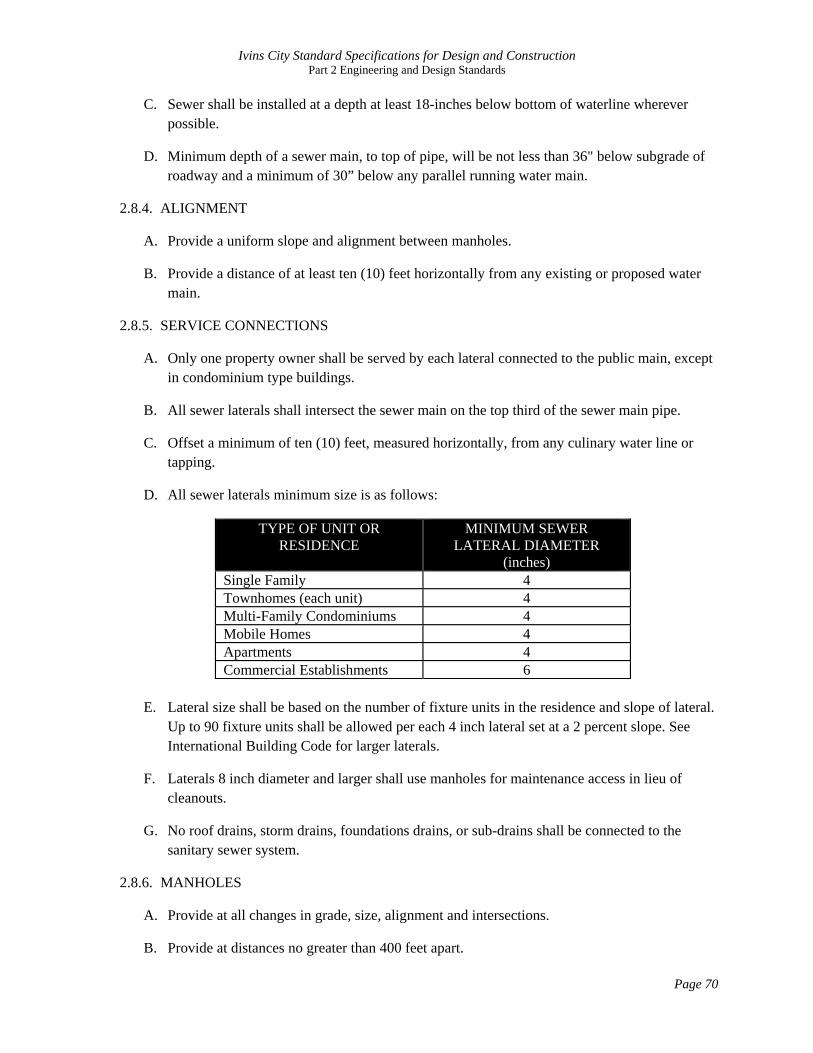
D. All sewer laterals minimum size is as follows:
TYPE OF UNIT OR RESIDENCE
MINIMUM SEWER LATERAL DIAMETER
(inches) Single Family 4 Townhomes (each unit) 4 Multi-Family Condominiums 4 Mobile Homes 4 Apartments 4 Commercial Establishments 6
E. Lateral size shall be based on the number of fixture units in the residence and slope of lateral.
Up to 90 fixture units shall be allowed per each 4 inch lateral set at a 2 percent slope. See International Building Code for larger laterals.
F. Laterals 8 inch diameter and larger shall use manholes for maintenance access in lieu of cleanouts.
G. No roof drains, storm drains, foundations drains, or sub-drains shall be connected to the sanitary sewer system.
2.8.6. MANHOLES
A. Provide at all changes in grade, size, alignment and intersections.
B. Provide at distances no greater than 400 feet apart.

Ivins City Standard Specifications for Design and Construction Part 2 Engineering and Design Standards
Page 71
C. City maintenance vehicle accessibility to all manholes is required.
D. Drop manholes shall be provided for a sewer line entering a manhole at an elevation of 18 inches or more above the manhole invert. Drop must be made on exterior of manhole unless otherwise approved by City.
E. Flow lines of straight through-lines (less than 10 degree horizontal bend) shall be graded through the manhole to match the average grade of the incoming and outgoing sewer pipes.
F. Flow lines of junction lines or bend lines greater than 10 degrees shall enter manhole 0.2 feet higher than the outgoing line.
G. When a smaller sewer joins a large one, the invert of the larger sewer should be lowered sufficiently to maintain the same energy gradient.
H. Manholes shall be a minimum 4-foot diameter.
I. Manholes shall be a minimum of 5-foot diameter if any of the following conditions exist:
1. Any sewer line is 12-inches or larger.
2. The junction of two or more inflowing sewerlines.
3. The flowline of the sewer is 12 feet or lower than the rim.
4. Drop manholes.
2.8.7. SEWER MAIN PIPELINES
A. Located within a dedicated right-of-way, sewer easement or equivalent. Sewer easements shall provide at least 20 feet of unobstructed width.
B. Pipelines must be installed straight between manholes/inlets. Curvilinear pipes are not allowed.
C. Approved Pipe Materials:
1. Solid Wall PVC, SDR 35, ASTM D3035
2. Ductile Iron, cement mortar lined
3. Other materials may be approved by the City Engineer on a case by case basis.
2.8.8. UTILTY CLEARANCES
A. Sewers crossing below water mains shall be separated by a minimum vertical distance of 18 inches.
B. Sewers crossing above water mains shall be laid to provide a minimum vertical distance of 18 inches between the outside of the water main and the outside of the sewer. Sewer joints shall

Ivins City Standard Specifications for Design and Construction Part 2 Engineering and Design Standards
Page 72
be spaced as far as possible from the crossing. (i.e. 10 feet when using 20-foot lengths of pipe)
C. When it is impossible to obtain proper horizontal and vertical separation as stated above, the sewer shall be designed and constructed of ductile iron pipe with mechanical joints for the minimum distance of 10 feet on either side of the point of crossing. Section must be pressure tested.
2.8.9. PUMPING AND FORCE MAINS
A. Generally not allowed except where shown on Ivins City Wastewater Capital Facilities Plan.
B. Pumps and equipment shall be located in an above ground building structure.
C. Pumps must be as manufactured by Gorman Rupp.
D. Other requirements may apply on a case by case basis.
E. Velocity of force main shall be never less than 3 feet per second.
F. Air relief valves may be required to prevent air lock. Air vent shall be filtered to prevent odor with an approved device.
G. No segment of force main shall have zero slope.
H. Force main shall discharge at a manhole and if necessary, provisions shall be made to direct or baffle sewage into the manhole.
I. Force main shall be designed to handle normal pressure, loads and surges. Calculations must be provided.
J. Force mains shall be installed with tracer wire.
K. Odor control equipment using charcoal filters or equivalent as approved by the City shall be installed on any manhole receiving a wastewater discharge from a force main or any other discharge that is expected to have become septic from periods of stagnation in a holding tank.
2.8.10. SUSPENDED CROSSINGS
A. Adequate support shall be provided for all joints.
B. Supports shall be designed to prevent frost heave, overturning and settlement.
C. Precautions to prevent freezing such as insulation or increased slope shall be provided.
D. The bottom of the pipe shall be set no lower than the 100 year flood elevation.
E. Supports shall be designed to allow for future grade adjustments.

Ivins City Standard Specifications for Design and Construction Part 2 Engineering and Design Standards
Page 73
2.9. WATER SYSTEM DESIGN
All culinary water mains and appurtenances shall be designed to provide for adequate future service for all contiguous areas which may, within a reasonable period of time, be tributary thereto.
2.9.1. DESIGN FLOW AND PRESSURES
A. Water mains shall be designed to provide a minimum residual pressure of 20 psi under peak day demand conditions, including designed fire flow.
B. A minimum of 40 psi residual pressure must be maintained under peak instantaneous conditions without fire flow.
C. Commercial or industrial areas may require special investigation to determine fire flow requirements.
D. Existing and future static pressure and flow information used in the design must be obtained from or approved by the City Engineer.
2.9.2. FLOW DESIGN CRITERIA
A. Use the following flow design criteria:
Peak Instant Peak Day Avg Annual Storage Requirement
Indoor Use Q (gpm) = 10.8 * ERU0.64
0.56 gpm per ERU
0.45 AF per ERU 400 gallons per ERU
Irrigation Use 9.8 gpm per irrigated acre
4.9 gpm per irrigated acre
3.26 AF per irrigated acre
4,964 gallons per irrigated acre
B. Minimum fire flow is 1,000 gpm for 2 hours for residential areas with dwellings no larger than 3,600 sq. ft per floor.
C. Fire flow for areas with larger residences and commercial residences should be as per International Building Code.
D. Water usage form (Form 7042) included in Appendix E shall be submitted with preliminary plan on subdivisions and with any application for site development.
2.9.3. HYDRAULIC ANALYSIS
A. A computer network model shall be required for all system expansions in accordance with State of Utah rules.
B. The model must show that the new expansion will not detrimentally impact other areas in the system.
Ivins City Standard Specifications for Design and Construction Part 2 Engineering and Design Standards
Page 74
2.9.4. MINIMUM SIZE AND DEPTH
A. The minimum depth of cover for water mains shall be 3 feet below the final grade of the street.
B. Where final grades have not been established, mains shall be installed at least 4 feet deep or greater to insure three feet of cover below the future grade based on the best information available.
C. The minimum size of a water main shall be not less than 4 inches in diameter.
D. The minimum size of a water main , with connecting hydrants, shall be not less than 8 inches in diameter.
E. Hydrant barrels and laterals to hydrants may be 6-inches in diameter.
F. Size of mains must be verified to be sufficient through an engineering analysis to meet the prescribed design flows and pressures.
2.9.5. VALVES
A. Valves shall be spaced and system must be looped such that:
1. No more than 2 fire hydrants will be isolated at any time.
2. No more than 30 services are isolated at any time.
3. A maximum of five valves will be required to isolate any location.
B. Install valves within 20 feet of the end of all temporary dead end lines.
C. Transmission mains may space valves at intervals of 2,500 feet when outside of a pressure zone
D. Gate valves shall be used on 12-inch pipe and smaller.
E. Gate valves or butterfly valves may be used on larger pipe.
F. All distribution mains connecting to larger supply mains shall be valved near the connection.
G. A valve near the main shall be located on all services and hydrant laterals greater than 2-inch in size.
H. Valves shall generally be located in clusters near a tee or cross.
2.9.6. DEADENDS
A. Dead-end mains shall be avoided wherever possible, and if installed, shall not exceed 600 feet.

Ivins City Standard Specifications for Design and Construction Part 2 Engineering and Design Standards
Page 75
B. Hydrants shall be located at the end of dead-end mains for flushing purposes as well as for fire protection.
C. Dead ends may have a 2-inch flush valve installed in lieu of a fire hydrant, if approved by the City on a case by case basis.
2.9.7. SERVICE CONNECTIONS
A. Pressure reducing devices shall be installed by the owner on all water connections to buildings.
B. Each service meter shall have a separate tap to the main.
C. Service line shall be located in a perpendicular alignment to the street.
D. Each building shall have a separate line and meter.
E. Service line size shall match the meter size. Beyond the meter, the line may be increased only one size.
F. Services shall be sized as follows:
SERVICE LINE SIZE MAXIMUM UNITS SERVED
3/4" 1 1” 5
1.5” 12 2” 20
2.9.8. FIRE HYDRANT SPACING AND LOCATION
A. Generally locate on the same sides of streets throughout a subdivision.
B. Fire hydrants are preferred near intersections.
C. In residential areas, fire hydrant spacing shall be no greater than 500 feet, and no house shall be greater than 250 feet from a hydrant via a street access to the property being served.
D. In industrial, business, or commercial areas, fire hydrant spacing shall not be greater than 350 feet, nor shall any building be greater than 175 feet from a hydrant via public access to the property being served.
E. Generally, hydrants shall be located in line with extensions of the property line when located mid-block.
F. Hydrants shall be placed in the park strip or, if there is no park strip, behind the sidewalk in such a manner than no part of hydrant encroaches on the walkway, and at such a height that lowest water outlet is not less than 18 inches nor more than 30 inches from the final ground elevation.

Ivins City Standard Specifications for Design and Construction Part 2 Engineering and Design Standards
Page 76
G. All fire hydrants shall be installed on dedicated easements or public rights-or-way, and will be owned and maintained by the City.
H. Hydrants shall have at least 5 feet clearance on sides and front and 3 feet on rear.
2.9.9. CULINARY WATER PIPELINES
A. Located within a dedicated right-of-way, waterline easement or equivalent. Waterline easements shall provide at least 20 feet of unobstructed width.
B. Install in straight segments between bends unless approved by the City.
C. Approved Pipe Materials:
1. Solid Wall PVC, AWWA C-900
2. Ductile Iron, Class 200, cement mortar lined, must be bagged to prevent corrosion.
3. Solid wall HDPE, submit calculations for wall thickness.
4. Steel, cement mortar lined and coated, submit calculations for wall thickness, must submit plan for cathodic protection.
2.9.10. NETWORK HYDRAULIC ANALYSIS
A. Required when:
1. The project is a major subdivision with an internally looped system.
2. The project is located in the higher elevations of a low static pressure zone.
3. A high fire flow demand is required (greater than1500 gallons per minute).
4. There will be extensive irrigation.
5. The new water plans will complete a loop on the current system.
6. As otherwise required by the City Engineer.
B. The consulting engineer should request the source hydraulic grade line (HGL) from the public works department prior to the initial design where a network hydraulic analysis is required.
C. Engineer must submit Water usage form (Form 7042) when requesting the HGL.
2.9.11. SECONDARY (IRRIGATION) WATER SYSTEM
A. Designed in accordance with all culinary water system requirements with the following exceptions:
Ivins City Standard Specifications for Design and Construction Part 2 Engineering and Design Standards
Page 77
1. Design pressures should be 10 psi higher than the culinary water system in the same pressure zone unless otherwise approved.
2. The pipe material shall be colored purple, or a discrete color different from the culinary water main.
3. There shall be no cross connection between secondary and culinary water systems.
4. Shall be installed at a minimum depth of 30 inches and generally installed above the culinary water line.

Ivins City Standard Specifications for Design and Construction Part 2 Engineering and Design Standards
Page 78
2.10. LIGHTING DESIGN
2.10.1. IVINS CITY STANDARD STREET LIGHT
Ivins City has selected the SpectraTM light fixture system as manufactured by Architectural Areal Lighting (AAL) as a standard for all City street lighting. All streetlights installed on public streets must use the SpectraTM system as herein described. Refer to AAL website at http://www.aal.net.
Table 2.10.1
Road Classification R/W
Width Pole
Height Spectra Fixture Lamp Ballast
Maximum Spacing
Minimum Spacing
Bollards on Paths Roundabouts
Major Arterial 100 18 SP1 IND 150W HPS 500' 250' Yes n/a Minor Arterial 80/85 18 SP1 IND 150W HPS 500' 250' Yes 4 Lights Major Collector 66 14 SP2 IND 100W HPS 400' 200' Yes n/a Minor Collector 60 14 SP2 IND 100W HPS 400' 200' No n/a Residential Collector 55 14 SP2 IND 100W HPS n/a 125' No n/a Residential 50 14 SP2 IND 100W HPS n/a 125' No n/a Resdiential Entrance n/a 14 SP2 IND 100W HPS n/a 125' N/a n/a R/W: Right of Way HPS: High Pressure Sodium
A. Light fixture:
1. Light fixture shall be AAL SpectraTM Model SP1 IND ULS or SP2 IND ULS in accordance with Table 14.1.
2. Fixture shall be equipped to cast an asymmetrical Type 3 light pattern for road side installations. Fixture shall cast a symmetrical Type 5 light pattern for median installations.
3. Fixture shall be glare free with an indirect lighting system that meets IES definition of “full cutoff” for night sky protection. Lamp Ballast shall be as identified in Table 2.10.1
B. Photocell:
1. Photocell shall be housed in an AAL Model PCA-C rotatable housing as manufactured by AAL.
2. Housing and photocell is mounted on top of pole and directly beneath light fixture on single fixture mounts or directly beneath the twin arm mount structure for double fixture mounts.
3. Rotatable housing shall be oriented to point photocell in direction of least luminance from adjacent light fixtures.
4. Housing shall be locked into place in accordance with manufacturer’s recommendations.

Ivins City Standard Specifications for Design and Construction Part 2 Engineering and Design Standards
Page 79
C. Pole:
1. Poles shall be Model PR4 as manufactured by AAL.
2. Poles shall be cast aluminum A356 alloy free of any porosity, foreign materials, or cosmetic fillers and shall be heat treated to a T-6 condition, of uniform wall thickness with no warping or mold shifting.
3. Aluminum poles shall have a 4-inch outside diameter with 0.226-inch wall thickness regardless of height.
4. Poles shall be bolted into a cast in place concrete foundation. Bolt size, length and pattern shall be according to the manufacturer.
D. Twin Arm Mounts: All light poles placed in medians on arterial or major collector roads shall be mounted with a twin arm mount AAL Model TAP1 (for SP1) or Model TAP2 (for SP2) for the placement of double fixtures.
E. Street Signage: Where poles are located at intersections, street signs shall be attached to pole.
F. Color: Poles, Base Covers, Arm Mounts, Adapters, Photocell Housing and Fixtures shall match in color and shall all be a standard color of CORTEN (CRT) as manufactured by AAL.
2.10.2. STREETLIGHT LOCATIONS
Streetlights shall be placed in accordance with the following:
A. Traffic Signalized Intersections:
1. All signalized intersections shall have SpectraTM SP1 IND 150 Watt HPS fixtures located on top of the signal pole.
2. The signal pole and signal cross arm shall match the AAL CORTEN color as best as possible.
B. Residential Entrances:
1. All residential developments accessed from arterial or collector roads shall have a streetlight consisting of a 14-foot pole mounted with a single SpectraTM SP2/IND3/ULS 100 Watt HPS fixture.
2. A residential entrance light will not be required if an adjacent residential entrance light is located within 125 feet on any arterial or major collector or within 250 feet on minor or residential collectors.
C. Major Arterials (Highway 91):
1. Streetlights, consisting of 18-foot poles mounted with single SpectraTM SP1/IND3/ULS 150 Watt HPS fixtures, shall be located at all intersections with

Ivins City Standard Specifications for Design and Construction Part 2 Engineering and Design Standards
Page 80
collector roads, located on two corners, and located diagonally across the intersection.
2. Only one light is required on T-intersections.
3. In commercial areas, twin arm mounted poles will be required in the street median in accordance with Table 2.10.1
D. Arterials (Snow Canyon Parkway/Center Street/Highway 91):
1. Streetlights, consisting of 18-foot poles mounted with single SpectraTM SP1/IND3/ULS 150 Watt HPS fixtures, shall be located at all intersections with collector roads, located on two corners, and located diagonally across the intersection.
2. Only one light is required on T-intersections.
3. Twin arm SpectraTM SP1/IND5/ULS 150 Watt HPS fixtures mounted on 14-foot poles will be required in the street medians in accordance with Table 2.10.1.
E. Major Collectors:
1. Streetlights, consisting of 14-foot poles mounted with single SpectraTM SP2/IND3/ULS 100 Watt HPS fixtures, shall be located at all intersections with collector roads, located on two corners, and located diagonally across the intersection.
2. Only one light is required on T-intersections.
3. Twin arm SpectraTM SP2/IND5/ULS 100 Watt HPS fixtures mounted on 14-foot poles will be required in the street medians in accordance with Table 2.10.1.
F. Minor/Residential Collectors:
1. A streetlight, consisting of a 14-foot pole mounted with a single SpectraTM SP2/IND3/ULS 100 Watt HPS fixture, shall be located at all intersections with collector roads, located on one corner of the intersection.
2.10.3. IVINS CITY STANDARD BOLLARD FOR PAVED TRAILS
Ivins City has selected the Bounce Bollard light fixture system as manufactured by Kim Lighting as a standard for all trail lighting. Refer to Kim website at http://www.kimlighting.com/.
A. Bollard Fixture:
1. Bollard fixture shall be the Bounce Bollard Model No. BNB as manufactured by Kim Lighting.
2. Lighting element shall be 70 Watt HPS.

Ivins City Standard Specifications for Design and Construction Part 2 Engineering and Design Standards
Page 81
3. Fixture shall include Optional Matte Black Body Cap (Cat. No. BBC) to meet IES designation for “full cutoff”.
B. Color: Bollard shall be a standard color of Dark Bronze as manufactured by Kim Lighting.
C. Locations: Bollard lighting of trails will be required on all arterial and major collector roads.
D. Spacing: Bollards shall be placed at a target spacing of 80 feet with a maximum spacing of 90 feet along these trails.
2.10.4. REQUIREMENTS FOR NEW DEVELOPMENT
A. Conduit, wiring and streetlights shall be installed at the developer’s expense in all new and proposed subdivisions or commercial areas.
B. Those subdivisions and commercial areas will be lighted in accordance with a written plan that addresses intersections, public facilities, trails and crosswalks. (See Zoning Ordinance Chapter 11 for details)
C. Non-Standard Lighting for New Development.
1. In the event that a new subdivision or commercial area presents a written lighting plan that uses non-standard streetlights, the plan must be approved by the Planning and Zoning Commission and the City Council.
2. All costs associated with installation, operation and maintenance of non-standard lights shall be by other than Ivins City.
3. All non-standard lighting must meet the requirements of Ivins City Outdoor Lighting Ordinance (Ord. No. 2007-11).
D. Exceptions may be made by the City Engineer or Public Works Director on the location of lighting if crosswalks and street signs along collector and arterial streets are provided with alternative lighting as proposed by a developer.
2.10.5. EXISTING SUBDIVISIONS
A. Existing subdivisions which do not want streetlights shall not be required to install them.
B. In the event a resident living in an established, built-out area requests the installation of a street light, the resident must have the approval and signatures of all adjoining residents impacted by the street light installation, and the City Council. The requesting resident is responsible for costs associated with the street light and its installation. The City will assume ownership after installation.
C. If an existing subdivision or project has non-standard lights installed, approval may be given to continue the non-standard street lights. All non-standard lights shall not be maintained by Ivins City unless already under Ivins City maintenance.

Ivins City Standard Specifications for Design and Construction Part 2 Engineering and Design Standards
Page 82
2.11. UTILITY LAYOUT
2.11.1. The following Design and Construction Standards are to be followed at all times, unless a problem exists. When the Standards cannot be followed, the City Engineer will be required to approve the alternative.
A. All utilities, i.e. gas, cable, power, sewer and water will be shown on the appropriate drawings.
B. Phone, cable and power joint trench will be located on the north and west side of roadways, back of sidewalk within new developments as much as possible. In planned developments without sidewalks, joint utility trench will be located 36 inches back of curb.
C. Gas mains will stay 5 feet minimum off of back of sidewalk on public streets.
D. Water will be located on south and east side of roadway 5 feet into roadway off of curb as much as possible or opposite power. In planned development, lip of curb for gas, water stays the same.
E. Water, sewer and drainage layout will be first utilities designed.
F. Generally, sewer will be located 10 feet off curb & gutter opposite of waterline. In private development or streets, the centerline will be used to align sewer as much as possible.
G. Generally, storm drain will be designed to fall at the inside lip of curb & gutter as per the detail.
H. Cable and phone boxes will be located on the right and left side of power transformers and secondary boxes. Cable will be on the left and phone on the right looking from the street.
I. Gas and water stubs will be placed 5 and 2 feet, respectively, to the right and left of the property lot line, with gas on the left and water on the right looking from the street.
J. Irrigation water mains should be generally installed 4’ away from waterline towards centerline of street.

Ivins City Standard Specifications for Design and Construction Part 2 Engineering and Design Standards
Page 83
THIS PAGE IS INTENTIONALLY BLANK
Ivins City Standard Specifications for Design and Construction Part 2 Engineering and Design Standards
Page 84
2.12. OTHER DESIGN CONSIDERATIONS
2.12.1. SENSITIVE LANDS
Ivins City has identified in the zoning ordinance lands that are considered sensitive and require special consideration. The Ivins City Sensitive Lands Map is available as part of the zoning ordinance which has inventoried on a broad scale which areas of the city are determined to contain sensitive lands. When a development is determined to contain sensitive lands, an application must be made in accordance with the Zoning Ordinance. The following lands are identified as sensitive:
A. All areas subject to flooding, as identified by the Ivins City Sensitive Lands Map, incorporated herein by reference.
B. All areas of wetlands, as identified by the Ivins City Sensitive Lands Map or as may be identified by the U.S. Army Corps of Engineers.
C. All areas where the increase or decrease in the elevation of the natural grade is equal to or greater than 8 percent, otherwise 1 foot of grade change for every 12-1/2 feet of horizontal run for a minimum distance of forty feet.
D. Habitat Conservation Plan areas, as identified on the Ivins City Sensitive Lands Map.
E. Areas of lava fields and rock outcroppings with an area of 8,000 square feet, or larger, as identified by the Ivins City Sensitive Lands Map.
F. Areas of known geologic hazards, as identified by the Ivins City Sensitive Lands Map, or as may be identified by a county, state, or federal agency with authority.
There are important design standards that should be considered by any designer for a development within these lands. It is recommended that the engineer/designer of any development become familiar with these guidelines in the initial planning stages.
2.12.2. IVINS CITY DESIGN GUIDELINES
Ivins City has developed and adopted design guidelines to promote a general level of design consistency, sensitivity to the scenic environment of Ivins, and to protect and promote the unique identity of the community. The objectives of the guidelines include:
• Promote the preservation of open spaces • Protect views • Promote compatibility between development and the natural environment • Promote a subdued character in buildings, lighting, and signage. • Promote continuity of streetscape design • Promote drought tolerant landscaping that is in harmony with the desert
environment

Ivins City Standard Specifications for Design and Construction Part 2 Engineering and Design Standards
Page 85
It is recommended that the designer of any development become familiar with these guidelines in the initial planning stages.
2.12.3. ZONING ORDINANCE STANDARDS
The adopted zoning ordinance has also developed General Development Standards (Chapter 11) and Supplementary Development Standards (Chapter 12) which provide additional design standards with which developments must comply.