part 175.d – data product specification – aeronautical ... · b.3 arinc 424 coding table...
TRANSCRIPT

Ensure document is current before use © Airservices Australia 2017 1 of 31
Part 175.D – Data Product Specification – Aeronautical Data Originators: Military Aerodromes
ATS-DPS-0007
Version 3
Effective 13 February 2018
Prepared: Sateesh Sathineni Aeronautical Data Analyst
Authorised: Grant Rawstorn ATM Data Services Manager

Part 175.D – Data Product Specification – Aeronautical Data Originators: Military Aerodromes
2 of 31 Version 3: Effective 13 February 2018 ATS-DPS-0007
Change summary Version Date Change description NRFC
2 18 December 2017 Significant changes to whole document 36548
3 13 February 2018 Include references to Waypoint reuse/relocation as per ICAO Annex 11 standards
36899
This document was created using Generic Document Template C-TEMP0047 Version 8.
Table of content 1 Background ............................................................................................................................... 3 2 Purpose ...................................................................................................................................... 3 3 Terms and Conditions .............................................................................................................. 3 4 Data Specification requirements ............................................................................................. 4 4.1 Notification date .......................................................................................................................... 4 4.2 Data requirements ....................................................................................................................... 4 4.3 Electronic format ......................................................................................................................... 4 4.4 Data alterations and error tracking .............................................................................................. 4 4.5 Data verification .......................................................................................................................... 4 4.6 Data integrity ............................................................................................................................... 4 4.7 NOTAM (applicable to military aerodromes) ............................................................................... 5 4.8 AIP Supplement .......................................................................................................................... 5 4.9 Attribute definitions (applicable to published data) ..................................................................... 5 5 Definitions .................................................................................................................................. 8 6 References ................................................................................................................................. 9 7 Appendixes ................................................................................................................................ 9 Appendix A .................................................................................................................................................. 10 A.1 Aerodrome data format prototype ............................................................................................. 10 A.2 Runway ..................................................................................................................................... 13 A.3 Runway direction ....................................................................................................................... 14 Appendix B .................................................................................................................................................. 16 B.1 Publication Process ................................................................................................................... 16 B.2 Design Style Guide ................................................................................................................... 17 B.3 ARINC 424 Coding Table (Template) ....................................................................................... 30 B.4 Procedure Verification Certificate (Template) ........................................................................... 31

Part 175.D – Data Product Specification – Aeronautical Data Originators: Military Aerodromes
ATS-DPS-0007 Version 3: Effective 13 February 2018 3 of 31
1 Background Airservices Australia (Airservices) under the Air Services Act 1995, provides aeronautical data/information necessary for the safety, regularity and efficiency of air navigation, giving effect to Australia’s obligation under the Chicago Convention on International Civil Aviation.
Civil Aviation Safety Regulation (CASR) Part 175 under the Civil Aviation Act 1988 establishes standards and requirements for the quality and integrity of data and information used in air navigation, in particular as published in the Aeronautical Information Publication (AIP), on aeronautical charts and contained within aeronautical navigation databases. Under CASR Part 175 Airservices must provide an aeronautical data originator (airport owner) with a Data Product Specification (DPS), so that aeronautical data can be obtained through a quality controlled process. Although the production of military instrument flight procedure (IFP) charts is regulated under the Defence Aviation Safety Regulations (DASR), a decision has been made, in conjunction with CASA, to include military IFP charts in the Australian AIP for completeness and situational awareness. DASR provide for a Defence Aeronautical Information Service Provider (AISP) to produce the Defence Aeronautical Information Publication (AIP) on behalf of the Defence Aviation Authority (Chief of Air Force). Air Force has traditionally acted as the Defence AISP, and the unit within Air Force tasked with that role is Aeronautical Information Service - Air Force (AIS-AF). Acceptable means of compliance to DASR include ICAO Annex 15, and as a result military IFP is designed, to the maximum extent possible to be PANS OPS compliant. Noting that AIS-AF is not a Part 173 of CASR certified organisation, the military IFP charts to be included in the Australian AIP are to be annotated as 'FOR MILITARY USE ONLY'.
2 Purpose The purpose of this document is to prescribe the information exchange protocols for the submission, modification and withdrawal of aeronautical data or information which may be published in the Integrated Aeronautical Information Publication (IAIP), or Aeronautical Datasets.
3 Terms and Conditions The term of this DPS starts on the Commencement Date and continues until replaced or revoked, in writing, by Airservices.
This document also establishes the processes and procedures for how the Provider must coordinate with Airservices in the publishing of Procedures in the Australian AIP

Part 175.D – Data Product Specification – Aeronautical Data Originators: Military Aerodromes
4 of 31 Version 3: Effective 13 February 2018 ATS-DPS-0007
4 Data Specification requirements
4.1 Notification date AIS-AF will make Airservices Australia aware of any likely changes to military IFP charts 6 weeks prior to ASA's 'ready for print' cut-off date, and will provide individual print ready PDF files of any new or amended IFP charts no later than 2 weeks prior to 'ready for print' cut-off date. The cut-off dates are available under http://www.airservicesaustralia.com/publications/document-amendment-calendar/
4.2 Data requirements Data entry format for aeronautical information used in AIP is defined in Appendix A and Appendix B. Incomplete information may be returned to the proponent for clarification purposes. Include structured sections and subsections as required relating information relevant to the topic/subject of the document.
4.3 Electronic format The authenticated electronic means through which aeronautical information and data is supplied to Airservices is by E-Mail. The common method to ensure that Airservices can readily identify any changes from existing published data or information is to use “mark-up” format to indicate where changes are required or to provide complete new text.
4.4 Data alterations and error tracking Requests for alterations to aeronautical data are to be communicated to Airservices through E-Mail request, in the format as specified in Appendix A and Appendix B to [email protected]. Airservices should be advised of any new, amended, or deleted information. Airservices should be notified when an error has occurred in the data or information.
Errors detected in the data must also be notified to: [email protected]
4.5 Data verification Data Originator must nominate to Airservices, persons who have the knowledge and competence to carry out the responsibilities of an “AIP responsible person”. An Aeronautical Data Originator registration form is available for this purpose in Airservices website and can also be requested from Airservices via E-Mail: [email protected]
4.6 Data integrity Source data can only be accepted from registered Aeronautical Data Originator. The data originator have an enduring responsibility for the accuracy levels of the data or information, and must ensure that the data is reviewed at least annually and immediately inform Airservices of any changes to the data.

Part 175.D – Data Product Specification – Aeronautical Data Originators: Military Aerodromes
ATS-DPS-0007 Version 3: Effective 13 February 2018 5 of 31
4.7 NOTAM (applicable to military aerodromes) AIS-Air Force will remain as the NOTAM originating authority for AIS-Air Force designed IFP charts. NOTAM requests must be submitted on the current Airservices NOTAM Request Form http://www.airservicesaustralia.com/flight-briefing/notam-originator/ unless other arrangements have been agreed to in writing by the NOTAM Office Line Manager. A NOTAM Originators Manual is provided http://www.airservicesaustralia.com/flight-briefing/notam-originator/ to assist data originators with submission of NOTAM requests. Data Originators must nominate to Airservices, persons who have the knowledge and competence to carry out the responsibilities of an “NOTAM authorised person”. This information must be kept always current. Data Originators must manage their “NOTAM authorised persons” through the NAIPS Internet Service (NIS) group management. 1. CASR Part 175.D provides the relevant detailed guidance for Data Originators and
their nomination of “NOTAM authorised persons”. 2. If the request for a NOTAM will change any existing published aeronautical data or
aeronautical information, the changes must be readily identifiable to the AIS provider.
3. CASR Part 175.470 identifies when consultation with aviation organisations must be undertaken.
4. The NOTAM Office must verify all NOTAM requests against the “NOTAM authorised persons” list.
5. NOTAM requests related to departure and approach procedures must be coordinated with the DAP Editor.
4.8 AIP Supplement Information promulgated by AIP Supplement, must be coordinated with Airservices and must adhere to the defined notifications periods required for the AIRAC.
4.9 Attribute definitions (applicable to published data) Attribute Description
Name of Owner/Person Responsible
Name of Owner, Operator or Person Responsible required for traceability
Owner/Operator Contact Details
Contact Details of Owner, Operator or Person Responsible
ARO Aerodrome Reporting Officer – Authorized contact person to update or amend information for Aerodrome
Landing site ID / ‘Y’ location code
Aerodrome identification ‘Y’ code
Landing site name Name of Landing site
Landing site Type ALA (Aircraft landing area), AD (Aerodrome) and HLS (Helicopter landing site)

Part 175.D – Data Product Specification – Aeronautical Data Originators: Military Aerodromes
6 of 31 Version 3: Effective 13 February 2018 ATS-DPS-0007
Attribute Description
Aerodrome Reference Point (ARP)
The geographic coordinates of the aerodrome reference point must be notified in degrees, minutes, seconds and 100
th of an arc second; based on the World Geodetic System-1984 (WGS-84). The ARP should be located at or near the centroid of the aerodrome. – Accuracy – 30M surveyed/calculated
State State in which the Aerodrome is located
Country Country in which the Aerodrome is located
Attribute Description
Aerodrome Highest Known Elevation
AD ELEV is shown in FT. When the ELEV is sea level, it will be indicated as 00. When the ELEV is BLW sea level, a minus sign will precede the figure. This figure is the ELEV of the highest point of the landing area highest known AMSL. – Accuracy – 0.5M surveyed
Aerodrome Diagram
An aerodrome diagram must be provided to illustrate layout of runways, taxiways, aprons etc.
Aerodrome Obstacle Chart Type A Charts
Aerodrome operators are responsible for Type A Chart information, (and the currency of this information).– local data may include obstacles in the circuit area
Aerodrome Obstacle Chart Type B Charts
Aerodrome operators are responsible for Type B Chart information, (and the currency of this information).
Precision Approach Terrain Charts
Aerodrome operators are responsible for Precision Approach Terrain Chart information (and the currency of this information).
Approach and Runway Lighting
a. Type, length and intensity of approach lighting system b. Runway threshold lights, colour and wing bars c. Type of visual approach slope indicator system d. Length of runway touchdown zone lights e. Length, spacing, colour and intensity of runway centreline lights f. Length, spacing, colour and intensity of runway edge lights g. Colour of runway end lights and wing bars h. Length and colour of stopway lights i. Operational specifications
Other Lighting and Secondary Power Supply
a. Location, characteristics and hours of operation of aerodrome beacon (if any) b. Lighting systems for taxiways c. Any other lighting systems d. Secondary power supply including switch-over time e. Operational specifications
Navigation Aids Where the aerodrome operator provides a navigation aid (VOR, DME, NDB), the location coordinates and operating frequency must be provided. The location co-ordinates must be notified in 100th of arc second, based on the World Geodetic System – 1984 (WGS-84). – Located at the AD – Accuracy 3M surveyed
Rescue and fire-fighting services
The category of aerodrome-based rescue and fire-fighting services provided by Airservices Australia or the aerodrome operator and operating hours

Part 175.D – Data Product Specification – Aeronautical Data Originators: Military Aerodromes
ATS-DPS-0007 Version 3: Effective 13 February 2018 7 of 31
Attribute Description
Collected Data Method the data was collected – Surveyed or Declared
Remarks Generic remarks regarding; AD charges, Prior Approval, Security Controlled etc.
Ground Services / Handling Services and Facilities
a. Fuel suppliers and their contact details, including after hours b. Automatic weather information broadcast if provided by aerodrome operator c. Ground to air communication systems such as Unicom, aerodrome frequency
response unit (AFRU) or approved air ground operator service provided by the aerodrome operator
d. Any other services available to pilots
Special Procedures Special procedures unique to the aerodrome, which pilots need to be advised; in cases where the flying procedure is generated by the aerodrome operator.
Notices Include important cautionary or administrative information relating to the use of the aerodrome.
Meteorological Information
Meteorological Information available
Operating Hours Hours of operation are shown where possible, usually displayed in Remarks.
Universal Time Coordinated
UTC – Time conversion-universal time coordinated (UTC) plus local time difference
Runway Designation
RWY are normally numbered in relation to their magnetic direction rounded off to the nearest 10 degrees. Single runways are shown with the lower number on the left side. Parallel runways designated Left/Right are shown with the left runway listed first. Multiple runways are shown in ascending order from top to bottom.
Runway Dimensions
The RWY length is generally the TKOF run (physical length) AVBL for both RWY directions. Runway lengths are shown as multiples of 100 FT. (e.g. Lengths of 6950 FT to 7049 FT are shown as 70, lengths of 7050 FT to 7149 FT are shown as 71.) – RWY Length Accuracy – 1M surveyed. The RWY width is the width FM side to side which contains the RWY, the graded and ungraded portions of the RWS, shown in meters only. The GRADED portion of the RWS is defined by boundary markers and is graded to alleviate damage to an ACFT in the event that it runs off the RWY. The UNGRADED portion of the RWS is free of upstanding objects but may contain depressions, trenches, etc.
Runway Surface a or A asphalt or bitumen;
b or B concrete;
c or C other surfaces (always to be qualified by a note).
Pavement Strengths The ICAO standard method of reporting pavement strength known as Aircraft Classification Number/Pavement Classification Number (ACN/PCN) has been incorporated.
Aerodrome Reference Code – Code Number(CN)
A reference code number is provided for each RWY listed in the RDS (in brackets after each RWY designation number). This code number indicates the maximum field length of the aeroplane that the RWY is designed for (based on the performance of the aircraft)

Part 175.D – Data Product Specification – Aeronautical Data Originators: Military Aerodromes
8 of 31 Version 3: Effective 13 February 2018 ATS-DPS-0007
Attribute Description
Runway Declared Distances
TORA (TAKE-OFF RUN AVAILABLE) The length of RWY declared available and suitable for the ground run of an ACFT taking off. (In most cases, this corresponds to the physical length of the RWY pavement.) (exclude clearway and stopway) – Accuracy 1M surveyed
TODA (TAKE-OFF DISTANCE AVAILABLE) The length of TKOF run available plus the length of any clearway (CWY) available. – Accuracy 1M surveyed
ASDA (ACCELERATE-STOP DISTANCE AVAILABLE) The length of TKOF run available, plus the length of the stopway (SWY), if provided. (Any SWY length included shall be adequate for use by all ACFT which comply with the RWY strength rating.) – Accuracy 1M surveyed
LDA (LANDING DISTANCE AVAILABLE) The length of RWY declared available and suitable for the ground run of an ACFT landing (LDG). (In most cases, this corresponds to the physical length of the RWY pavement, THR to RWY end, excluding any displacement of threshold, stopway, and clearway) – Accuracy 1M surveyed.
5 Definitions Within this document, the following definitions apply:
Term Definition
AIP Aeronautical Information Publication
AIRAC Aeronautical Information Regulation and Control
AMSL Above Mean Sea Level
CASA Civil Aviation Safety Authority
CASR Civil Aviation Safety Regulation
DPS Data Product Specification

Part 175.D – Data Product Specification – Aeronautical Data Originators: Military Aerodromes
ATS-DPS-0007 Version 3: Effective 13 February 2018 9 of 31
Term Definition
IAIP Integrated Aeronautical Information Package (including AIP charts)
ICARD International Codes and Routes Designators
WGS-84 World Geographic System 1984
UOM Unit of Measurement
6 References Title
ICAO Annex 4: Aeronautical Charts
ICAO Annex 11: Air Traffic Services
ICAO Annex 6: Operation of Aircraft
ICAO Annex 14: Aerodromes
ICAO Annex 15: Aeronautical Information Services
ICAO Doc 8126: Aeronautical Information Services Manual
ICAO Doc 8168: Flight procedures
CASA Part 139: Manual of Standards Aerodromes
CASR Part 173: Instrument Flight Procedure Design
CASR Part 175: Aeronautical Information Management
MOS Part 139: Aerodromes
ISO 9001:2015 Quality Management
NOTAM Originators Manual http://www.airservicesaustralia.com/wp-content/uploads/NOTAM-Originators-Manual-V1.1.pdf
7 Appendixes Appendix A
Appendix B

Part 175.D – Data Product Specification – Aeronautical Data Originators: Military Aerodromes
10 of 31 Version 3: Effective 13 February 2018 ATS-DPS-0007
Appendix A
A.1 Aerodrome data format prototype REQUIRED INFORMATION
FORMAT REQUIRED ACCEPTED CODE LIST EXAMPLE
Name of Owner/Operator
[CHAR] Required Sam Smith
Owner/Operator Contact Details
[CHAR] Required Address: 123 Aerodrome Lane, Suburb ACT 2601 Ph: 02 6200 0000 Email: [email protected]
Aerodrome Reporting Officer(s) (ARO)
[CHAR] Required Sam Smith, John Smith and Sally Smith
Aerodrome Name [CHAR] Required Aerodrome Hills Aerodrome ‘Y’ code
[CHAR] Required YXXX
Aerodrome Type [CHAR] Required ALA, AD, HLS Collected Data [CHAR] Required Surveyed
Declared Calculated
Surveyed
Aerodrome Usage Classification
CERT Certified Aerodrome PUBLIC AVBL all classes of OPS PVT (PRIVATE) – PPR from Facility Operator REG Registered Aerodrome MIL (MILITARY) – PPR for civil OPS class UNCR Uncertified or Unregistered JOINT Civil/Military Aerodrome OTHR Certain Other
State [CHAR] Optional ACT – Australian Capital Territory NSW – New South Wales NT – Northern Territory QLD – Queensland SA – South Australia TAS – Tasmania VIC – Victoria WA –Western Australia
ACT
Country [CHAR] Optional AUS – AUSTRALIA AUS Horizontal Datum [CHAR] Required WGS-84 WGS-84 ARP Latitude [LAT] Required [S]DD MM SS.SS S34 17 41.20 ARP Longitude [LONG] Required [E]DDD MM SS.SS E148 51 34.60 Aerodrome Highest known Elevation
[Integer] Required AMSL UOM = FT - Feet
444 FT
Operating Hours [CHAR] Required Aerodrome Operating Hours 2200-1300 MON-THU, 2200- 0430 FRI
Part 175.D – Data Product Specification – Aeronautical Data Originators: Military Aerodromes
ATS-DPS-0007 Version 3: Effective 13 February 2018 11 of 31
REQUIRED INFORMATION
FORMAT REQUIRED ACCEPTED CODE LIST EXAMPLE
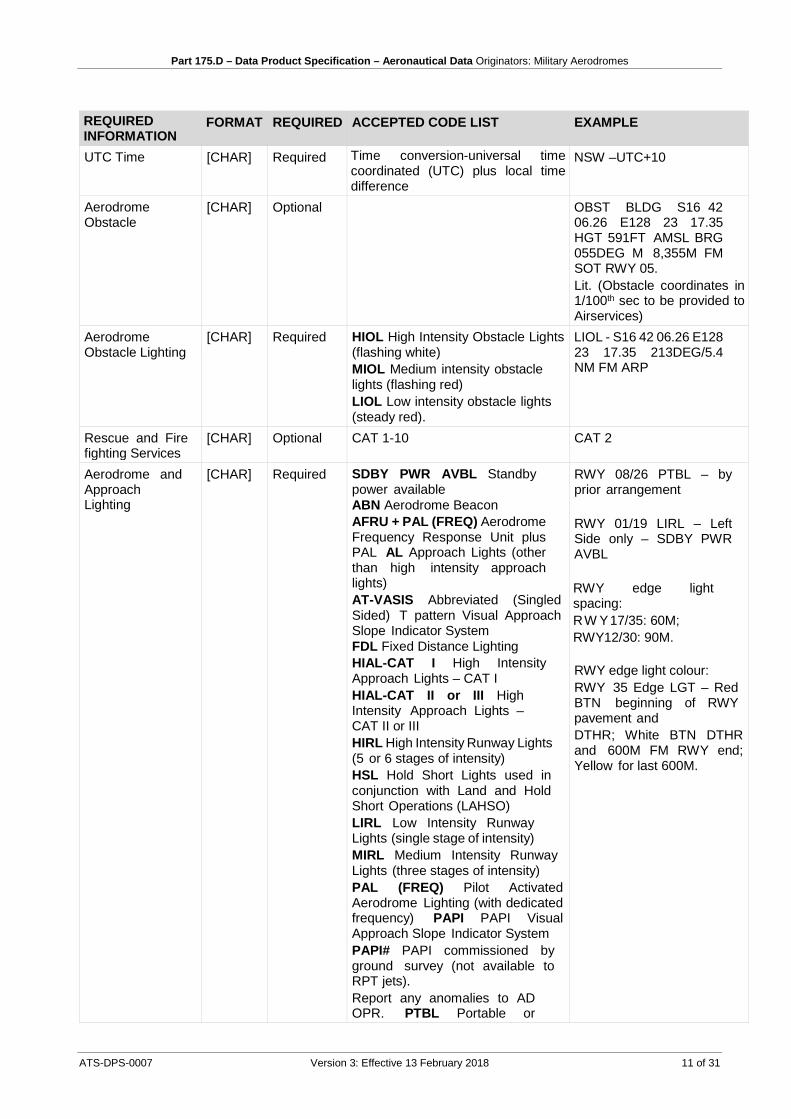
UTC Time [CHAR] Required Time conversion-universal time coordinated (UTC) plus local time difference
NSW –UTC+10
Aerodrome Obstacle
[CHAR] Optional OBST BLDG S16 42 06.26 E128 23 17.35 HGT 591FT AMSL BRG 055DEG M 8,355M FM SOT RWY 05. Lit. (Obstacle coordinates in 1/100th sec to be provided to Airservices)
Aerodrome Obstacle Lighting
[CHAR] Required HIOL High Intensity Obstacle Lights (flashing white) MIOL Medium intensity obstacle lights (flashing red) LIOL Low intensity obstacle lights (steady red).
LIOL - S16 42 06.26 E128 23 17.35 213DEG/5.4 NM FM ARP
Rescue and Fire fighting Services
[CHAR] Optional CAT 1-10 CAT 2
Aerodrome and Approach Lighting
[CHAR] Required SDBY PWR AVBL Standby power available ABN Aerodrome Beacon AFRU + PAL (FREQ) Aerodrome Frequency Response Unit plus PAL AL Approach Lights (other than high intensity approach lights) AT-VASIS Abbreviated (Singled Sided) T pattern Visual Approach Slope Indicator System FDL Fixed Distance Lighting HIAL-CAT I High Intensity Approach Lights – CAT I HIAL-CAT II or III High Intensity Approach Lights – CAT II or III HIRL High Intensity Runway Lights (5 or 6 stages of intensity) HSL Hold Short Lights used in conjunction with Land and Hold Short Operations (LAHSO) LIRL Low Intensity Runway Lights (single stage of intensity) MIRL Medium Intensity Runway Lights (three stages of intensity) PAL (FREQ) Pilot Activated Aerodrome Lighting (with dedicated frequency) PAPI PAPI Visual Approach Slope Indicator System PAPI# PAPI commissioned by ground survey (not available to RPT jets). Report any anomalies to AD OPR. PTBL Portable or
RWY 08/26 PTBL – by prior arrangement RWY 01/19 LIRL – Left Side only – SDBY PWR AVBL RWY edge light spacing: RW Y17/35: 60M; RWY12/30: 90M. RWY edge light colour: RWY 35 Edge LGT – Red BTN beginning of RWY pavement and DTHR; White BTN DTHR and 600M FM RWY end; Yellow for last 600M.

Part 175.D – Data Product Specification – Aeronautical Data Originators: Military Aerodromes
12 of 31 Version 3: Effective 13 February 2018 ATS-DPS-0007
REQUIRED INFORMATION
FORMAT REQUIRED ACCEPTED CODE LIST EXAMPLE
Remarks [CHAR] Optional This AD is a Security Controlled Airport
Ground Services [CHAR] Optional AIRPORT FUEL FACILITY: Phone 02 6200 0000, FAX 6200 0000, Managing Agent Caltex. Caltex – JET A1, Shell – JET A1, Aerorefuellers – AVGAS via bowser only. AVGAS self-serve (accepts Aero Refuel Card, V and MC – unsuitable for fixed wing aircraft with wing span greater than 12M).
Additional Information
[CHAR] Optional Possibility of Kangaroos on movement area.
Radio Navigation and Landing Aids
[CHAR] Optional 1. VOR CB 116.7 S35 16 09.25 E149 11 15.29
2. DME CB 116.7/114X S35 16 36.45 E149 11 25.46
3. Outside TWR HR all NAVAIDS are Pilot Monitored.
Local Traffic Regulations
[CHAR] Optional 1. High terrain in CCT area. All CCTs left hand.
2. All aircraft must provide their parked position/gate number to ATC on acknowledgement of
temporary lights (flares or battery) RCGL Runway Circling Guidance Lights RCLL Runway Centre Line Lights REDL Runway Edge Lights RGL Runway Guard Lights (Alternating Flashing Yellow) RLLS Runway Lead-in Lighting RTIL Runway Threshold Identification Lights (flashing white) RTZL Runway Touchdown Zone Lights SALS Simple Approach Lighting System SFL Sequenced Flashing Lights STWL Stopway Light(s) T –VASIS T pattern Visual Approach Slope Indicator System Taxiways Centerline lights are green and edge lights are blue

Part 175.D – Data Product Specification – Aeronautical Data Originators: Military Aerodromes
ATS-DPS-0007 Version 3: Effective 13 February 2018 13 of 31
REQUIRED INFORMATION
FORMAT REQUIRED ACCEPTED CODE LIST EXAMPLE
airways clearance. All right hand CCT operations must be approved by CASA.
Flight Procedures [CHAR] Required Low Visibility Operations For CASA APV operators, all RWYs are capable of supporting low VIS take-offs without limit, however only: a. RWY 16 and 27 are
normally used for low VIS departures; and
b. RWY 16 is capable of supporting localiser guided take-offs.
Charts Related to Aerodrome (Type A/B Charts and DAP/WAC)
[CHAR] Required Aerodrome Obstruction Chart Type A: RWY 12 Edition 3 (November 2008). RWY 30 Edition 5 (March 2012) Charts also to be provided so they will be provided access to public under Precision Approach Terrain Charts and Type A & Type B Obstacle Charts in Airservices website.
A.2 Runway REQUIRED INFORMATION
FORMAT REQUIRED ACCEPTED CODE LIST EXAMPLE
RWY Designation (ID)
[CHAR] Required 01/19
RWY Surface [CHAR] Required a or A asphalt or bitumen; b or B concrete; c or C other surfaces (always to be qualified by a note)
A
Pavement Type for ACN-PCN Determination
[CHAR] Required Pavement type Code Rigid pavement R Flexible pavement F
F
Subgrade Strength Category
[CHAR] Subgrade strength category Code High strength A Medium strength B Low strength C Ultra low strength D
B
Maximum Tyre Pressure
[Integer] Required UOM – Kpa – Kilopascals 1,750 Kpa
RWY Length [Integer] Required UOM – M – Metres 2,530M RWY Width [Integer] Required UOM – M – Metres 45M

Part 175.D – Data Product Specification – Aeronautical Data Originators: Military Aerodromes
14 of 31 Version 3: Effective 13 February 2018 ATS-DPS-0007
REQUIRED INFORMATION
FORMAT REQUIRED ACCEPTED CODE LIST EXAMPLE
RWY Strip Graded Width
[Integer] Required UOM – M – Metres 150M
RWY Strip Width [Integer] Required UOM – M – Metres 300M
A.3 Runway direction REQUIRED INFORMATION
FORMAT REQUIRED ACCEPTED CODE LIST EXAMPLE
RWY Designation (ID)
[CHAR] Required 01
Threshold Latitude / Helipad Latitude
[LAT] Required [S]DD MM SS.SS S35 17 26.24
Threshold Longitude / Helipad Longitude
[LONG] Required [E]DDD MM SS.SS E149 11 40.01
Displaced Threshold Latitude
[LAT] If applicable [S]DD MM SS.SS S35 17 25.22
Displaced Threshold Longitude
[LONG] If applicable [E]DDD MM SS.SS E149 11 40.01
RWY End Latitude
[LAT] Required [S]DD MM SS.SS S35 17 25.22
RWY End Longitude
[LONG] Required [E]DDD MM SS.SS E149 11 40.01
Threshold Elevation
[Integer] Required UOM; FT – Feet 16.00 FT
RWY Slope [CHAR] Required RWY 12/30 – 0.7% down to NW
Aerodrome Reference Code – Code Number (CN)
[Integer or CHAR]
Required 1 . Field length of less than 800M
2 . Field length of 800M up to, but not including, 1200M
3. Field length of 1200M up to but not including 1800M.
4. Field length of 1800M and over.
MIL – For Military aerodromes
RWY CN - 02 RWY CN - MIL
TORA (Take-Off run available
[Integer] Required UOM - M - Metres 2,530M
TODA (Take-Off distance available
[Integer] Required UOM - M - Metres 2,620M
TODA Gradient [Integer] Required 4.85% ASDA (Accelerate-Stop distance available)
[Integer] Required UOM - M - Metres 2,560M
LDA (Landing distance available)
[Integer] Required UOM - M - Metres 2,530M

Part 175.D – Data Product Specification – Aeronautical Data Originators: Military Aerodromes
ATS-DPS-0007 Version 3: Effective 13 February 2018 15 of 31
REQUIRED INFORMATION
FORMAT REQUIRED ACCEPTED CODE LIST EXAMPLE
STODA – (Supplementary Take-Off distance available)
[Integer] Optional
1.6 1.9 2.2 2.5 3.3 5.0 UOM - M - Metres
RWY 05 – 1.6% - 2389 1.9% - 2547
Copies of AIP, ERSA, DAP and DAH are available for review: http://www.airservicesaustralia.com/publications/aeronautical-information-package-aip/

Part 175.D – Data Product Specification – Aeronautical Data Originators: Military Aerodromes
16 of 31 Version 3: Effective 13 February 2018 ATS-DPS-0007
Appendix B
B.1 Publication Process The Provider will follow the publication process for Procedures as set out below:
1) All procedures must be presented in accordance with the Design Style Guide as described in this document.
2) All waypoint identifiers are to be obtained/checked and approved by the ATM Data Services prior to the submission of any design for publishing. Requests are to be sent to: [email protected]
3) When there is a need to relocate a waypoint, a new IDENT shall be requested. Allocated waypoint IDENT cannot be re-used if the coordinates are changed subsequent to the waypoint IDENT allocation. Previously used waypoint IDENT can only be reused at a different location after a period of six months subject to availability and proximity checks done by ATM Data Services.
4) During the design or amendment of a Procedure by the Provider (which will require publication by the ATM Data Services), the Provider must seek Air Traffic Control coordination in order to determine if there is any effect on existing procedures or other potential safety issues (refer Notes at the end of this section)
5) A final Procedure Chart in the format required by the ATM Data Services, and as detailed in the Design Style Guide should be sent to: [email protected]
6) If the new Procedure is at a location that does not currently have an Aerodrome Chart then one is to be provided by the Provider as detailed in the Design Style Guide. This should be sent to: [email protected]
7) The Procedure, when supplied to Airservices, is to include the following information: a) a copy of the Procedure Verification Certificate (template attached)
acknowledging/verifying that all approvals have been given, and with all supporting documentation, in electronic format, attached;
b) a copy of any correspondence provided by Air Traffic Control, (including confirmation that the required coordination by Air Traffic Control has occurred);
c) a list of critical obstacles relevant to the procedures provided, as well as any available survey reports;
d) a list of waypoint coordinates (coordinate definition is to be 1/100 of a second of arc in WGS-84) relevant to the procedures provided;
e) a copy of the Procedure in Adobe PDF format Version 9 (unless otherwise advised by Airservices) with the effective date and page reference numbers enabled as editable;
8) Airservices will advise of the likely publication date using the e-mail address of the Provider as detailed in the Procedure Verification Certificate.
9) The Provider shall monitor NOTAM published by the NOTAM Office (NOF), to guarantee integrity of a designed Procedure. The Provider shall notify the ATM Data Services and NOF of Procedure amendments, as required.

Part 175.D – Data Product Specification – Aeronautical Data Originators: Military Aerodromes
ATS-DPS-0007 Version 3: Effective 13 February 2018 17 of 31
10) If a Provider determines that a NOTAM is required, all details are to be provided to: [email protected]
11) The use of any Waypoints must be coordinated with Airservices by sending an email to [email protected]
All waypoints (except RNAV (GNSS)) must be obtained from Airservices, the waypoint can only be published after ICAO approved the intended use of the applicable waypoint based on a proximity check in the ICAO ICARD (International Codes and Routes Designators) system.
12) RNAV (GNSS) Procedure waypoints shall be named using a unique five letter code and should not be pronounceable, eg: SCBWA.
• The first three letters will be the last three letters of the airport ICAO code identifier (eg: SCB for YSCB). An alternative is the use of the aerodrome IATA code, where the ICAO code is not available for use. Airservices will advise the first three letters where ICAO and IATA codes are not available.
• The fourth letter will be the direction from which the procedure approaches the airport (eg: N, S, E, or W). It should be based on true direction; however exceptions can be made with reasoning.
• The fifth letter will identify the procedure fix type (I for the IF, F for the FAF, M for the MAPt, T for the MATF and H for the MAHF).
• A right hand offset IAF of the first RNAV procedure at an aerodrome shall be suffixed by the letter ‘A’. Subsequent IAF’s shall have their suffix increment alphabetically clockwise around the aerodrome. The suffix reserved for subsequent fixes, and other uses, shall not be used. This will exclude ‘I’, ‘F’, ‘M’, ‘T’,’H’, ‘O’ and combination ‘NB’ (where procedure is from North). IAF letters should not be used more than once at an aerodrome.
NOTES:
1. All relevant Aeronautical Data provided to Airservices will be included in the state AIP.
B.2 Design Style Guide This style guide consists of sample charts for the following chart types:
• Aerodrome Chart • Apron Chart • Standard Instrument Departure (SID) Procedure • Standard Terminal Arrival Route (STAR) Procedure • NDB Procedure • VOR/DME Procedure • ILS and/or LOC Procedure • DME or GNSS Arrival Procedure • RNAV (GNSS) Procedure • RNAV (GNSS) Baro-VNAV Procedure

Part 175.D – Data Product Specification – Aeronautical Data Originators: Military Aerodromes
18 of 31 Version 3: Effective 13 February 2018 ATS-DPS-0007
B.2.1 Aerodrome Chart (Page 1)

Part 175.D – Data Product Specification – Aeronautical Data Originators: Military Aerodromes
ATS-DPS-0007 Version 3: Effective 13 February 2018 19 of 31
B.2.2 Apron Chart
Part 175.D – Data Product Specification – Aeronautical Data Originators: Military Aerodromes
20 of 31 Version 3: Effective 13 February 2018 ATS-DPS-0007
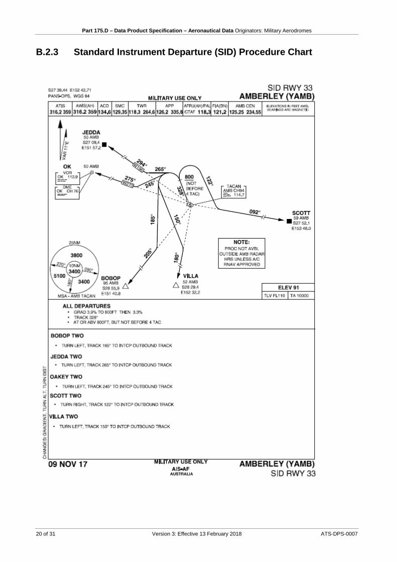
B.2.3 Standard Instrument Departure (SID) Procedure Chart

Part 175.D – Data Product Specification – Aeronautical Data Originators: Military Aerodromes
ATS-DPS-0007 Version 3: Effective 13 February 2018 21 of 31
B.2.4 Standard Arrival Route (STAR) Chart

Part 175.D – Data Product Specification – Aeronautical Data Originators: Military Aerodromes
22 of 31 Version 3: Effective 13 February 2018 ATS-DPS-0007
B.2.5 NDB Procedure Chart

Part 175.D – Data Product Specification – Aeronautical Data Originators: Military Aerodromes
ATS-DPS-0007 Version 3: Effective 13 February 2018 23 of 31
B.2.6 ARA Procedure Chart

Part 175.D – Data Product Specification – Aeronautical Data Originators: Military Aerodromes
24 of 31 Version 3: Effective 13 February 2018 ATS-DPS-0007
B.2.7 ILS Procedure Chart

Part 175.D – Data Product Specification – Aeronautical Data Originators: Military Aerodromes
ATS-DPS-0007 Version 3: Effective 13 February 2018 25 of 31
B.2.8 LOC Procedure Chart

Part 175.D – Data Product Specification – Aeronautical Data Originators: Military Aerodromes
26 of 31 Version 3: Effective 13 February 2018 ATS-DPS-0007
B.2.9 TACAN Procedure Chart

Part 175.D – Data Product Specification – Aeronautical Data Originators: Military Aerodromes
ATS-DPS-0007 Version 3: Effective 13 February 2018 27 of 31
B.2.10 RNAV (GNSS) Procedure Chart

Part 175.D – Data Product Specification – Aeronautical Data Originators: Military Aerodromes
28 of 31 Version 3: Effective 13 February 2018 ATS-DPS-0007
B.2.11 RNAV (GNSS) Procedure Chart- Baro-VNAV

Part 175.D – Data Product Specification – Aeronautical Data Originators: Military Aerodromes
ATS-DPS-0007 Version 3: Effective 13 February 2018 29 of 31
INTENTIONALLY LEFT BLANK
Part 175.D – Data Product Specification – Aeronautical Data Originators: Military Aerodromes
30 of 31 Version 3: Effective 13 February 2018 ATS-DPS-0007
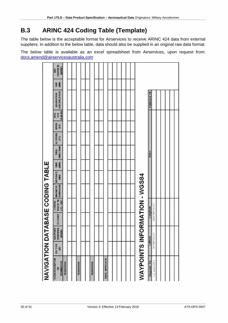
B.3 ARINC 424 Coding Table (Template) The table below is the acceptable format for Airservices to receive ARINC 424 data from external suppliers. In addition to the below table, data should also be supplied in an original raw data format.
The below table is available as an excel spreadsheet from Airservices, upon request from: [email protected]

Part 175.D – Data Product Specification – Aeronautical Data Originators: Military Aerodromes
ATS-DPS-0007 Version 3: Effective 13 February 2018 31 of 31
B.4 Procedure Verification Certificate (Template)