part 15.4: wireless medium access control (mac) and
TRANSCRIPT

IEEE Std 802.15.4™-2006(Revision of
IEEE Std 802.15.4-2003)
IEEE Standard for Information technology—
Telecommunications and information exchange between systems—
Local and metropolitan area networks— Specific requirements
Part 15.4: Wireless Medium Access Control(MAC) and Physical Layer (PHY)Specifications for Low-Rate WirelessPersonal Area Networks (WPANs)
I E E E3 Park Avenue New York, NY 10016-5997, USA
8 September 2006
IEEE Computer SocietySponsored by theLAN/MAN Standards Committee

The Institute of Electrical and Electronics Engineers, Inc.3 Park Avenue, New York, NY 10016-5997, USA
Copyright © 2006 by the Institute of Electrical and Electronics Engineers, Inc.All rights reserved. Published 8 September 2006. Printed in the United States of America.
IEEE and 802 are registered trademarks in the U.S. Patent & Trademark Office, owned by the Institute of Electrical andElectronics Engineers, Incorporated.
Print: ISBN 0-7381-4996-9 SH95552PDF: ISBN 0-7381-4997-7 SS95552
No part of this publication may be reproduced in any form, in an electronic retrieval system or otherwise, without the priorwritten permission of the publisher.
IEEE Std 802.15.4™-2006(Revision of
IEEE Std 802.15.4-2003)
IEEE Standard forInformation technology—Telecommunications and information exchange
between systems—Local and metropolitan area networks—Specific requirements—
Part 15.4: Wireless Medium Access Control (MAC) and Physical Layer (PHY) Specifications for Low-Rate Wireless Personal Area Networks (WPANs)
Sponsor
LAN/MAN Standards Committeeof theIEEE Computer Society
Approved 7 June 2006
IEEE-SA Standards Board
Abstract: IEEE Std 802.15.4-2003 defined the protocol and compatible interconnection for datacommunication devices using low-data-rate, low-power, and low-complexity short-range radiofrequency (RF) transmissions in a wireless personal area network (WPAN). This revision extendsthe market applicability of IEEE Std 802.15.4, removes ambiguities in the standard, and makesimprovements revealed by implementations of IEEE Std 802.15.4-2003.Keywords: ad hoc network, low data rate, low power, LR-WPAN, mobility, PAN, personal areanetwork, radio frequency, RF, short range, wireless, wireless personal area network, WPAN

IEEE Standards documents are developed within the IEEE Societies and the Standards CoordinatingCommittees of the IEEE Standards Association (IEEE-SA) Standards Board. The IEEE develops its standardsthrough a consensus development process, approved by the American National Standards Institute, which bringstogether volunteers representing varied viewpoints and interests to achieve the final product. Volunteers are notnecessarily members of the Institute and serve without compensation. While the IEEE administers the process andestablishes rules to promote fairness in the consensus development process, the IEEE does not independentlyevaluate, test, or verify the accuracy of any of the information contained in its standards.
Use of an IEEE Standard is wholly voluntary. The IEEE disclaims liability for any personal injury, property orother damage, of any nature whatsoever, whether special, indirect, consequential, or compensatory, directly orindirectly resulting from the publication, use of, or reliance upon this, or any other IEEE Standard document.
The IEEE does not warrant or represent the accuracy or content of the material contained herein, and expresslydisclaims any express or implied warranty, including any implied warranty of merchantability or fitness for aspecific purpose, or that the use of the material contained herein is free from patent infringement. IEEE Standardsdocuments are supplied “AS IS.”
The existence of an IEEE Standard does not imply that there are no other ways to produce, test, measure,purchase, market, or provide other goods and services related to the scope of the IEEE Standard. Furthermore, theviewpoint expressed at the time a standard is approved and issued is subject to change brought about throughdevelopments in the state of the art and comments received from users of the standard. Every IEEE Standard issubjected to review at least every five years for revision or reaffirmation. When a document is more than fiveyears old and has not been reaffirmed, it is reasonable to conclude that its contents, although still of some value,do not wholly reflect the present state of the art. Users are cautioned to check to determine that they have the latestedition of any IEEE Standard.
In publishing and making this document available, the IEEE is not suggesting or rendering professional or otherservices for, or on behalf of, any person or entity. Nor is the IEEE undertaking to perform any duty owed by anyother person or entity to another. Any person utilizing this, and any other IEEE Standards document, should relyupon the advice of a competent professional in determining the exercise of reasonable care in any givencircumstances.
Interpretations: Occasionally questions may arise regarding the meaning of portions of standards as they relate tospecific applications. When the need for interpretations is brought to the attention of IEEE, the Institute willinitiate action to prepare appropriate responses. Since IEEE Standards represent a consensus of concernedinterests, it is important to ensure that any interpretation has also received the concurrence of a balance ofinterests. For this reason, IEEE and the members of its societies and Standards Coordinating Committees are notable to provide an instant response to interpretation requests except in those cases where the matter has previouslyreceived formal consideration. At lectures, symposia, seminars, or educational courses, an individual presentinginformation on IEEE standards shall make it clear that his or her views should be considered the personal views ofthat individual rather than the formal position, explanation, or interpretation of the IEEE.
Comments for revision of IEEE Standards are welcome from any interested party, regardless of membershipaffiliation with IEEE. Suggestions for changes in documents should be in the form of a proposed change of text,together with appropriate supporting comments. Comments on standards and requests for interpretations shouldbe addressed to:
Secretary, IEEE-SA Standards Board445 Hoes LanePiscataway, NJ 08854USA
Authorization to photocopy portions of any individual standard for internal or personal use is granted by theInstitute of Electrical and Electronics Engineers, Inc., provided that the appropriate fee is paid to CopyrightClearance Center. To arrange for payment of licensing fee, please contact Copyright Clearance Center, CustomerService, 222 Rosewood Drive, Danvers, MA 01923 USA; +1 978 750 8400. Permission to photocopy portions ofany individual standard for educational classroom use can also be obtained through the Copyright ClearanceCenter.

Introduction
This standard defines the protocol and interconnection of devices via radio communication in a personalarea network (PAN). The standard uses carrier sense multiple access with collision avoidance (CSMA-CA)medium access mechanism and supports star as well as peer-to-peer topologies. The media access iscontention based; however, using the optional superframe structure, time slots can be allocated by the PANcoordinator to devices with time critical data. Connectivity to higher performance networks is providedthrough a PAN coordinator.
This revision was initiated to incorporate additional features and enhancements as well as somesimplifications to the 2003 edition of this standard. The standard now includes two optional physical layers(PHYs) yielding higher data rates in the lower frequency bands and, therefore, specifies the following fourPHYs:
— An 868/915 MHz direct sequence spread spectrum (DSSS) PHY employing binary phase-shiftkeying (BPSK) modulation
— An 868/915 MHz DSSS PHY employing offset quadrature phase-shift keying (O-QPSK)modulation
— An 868/915 MHz parallel sequence spread spectrum (PSSS) PHY employing BPSK and amplitudeshift keying (ASK) modulation
— A 2450 MHz DSSS PHY employing O-QPSK modulation
The 868/915 MHz PHYs support over-the-air data rates of 20 kb/s, 40 kb/s, and optionally 100kb/s and250kb/s. The 2450 MHz PHY supports an over-the-air data rate of 250 kb/s. The PHY chosen depends onlocal regulations and user preference.
This revision also incorporates the following additions and enhancements to the 2003 edition:— Adds support for a shared time base through the addition of a data time stamping mechanism— Adds extensions of the 2.4GHz derivative modulation yielding higher data rates at the lower
frequency bands— Incorporates a mechanism for communicating the revision level on a frame-by-frame basis— Adds support for beacon scheduling— Allows synchronization of broadcast messages in beacon-enabled PANs— Improves usage of security suite
Also, this revision incorporates the following changes and simplifications:— Makes GTS support optional— Removes restrictions for manually enabling the receiver— Simplifies passive and active scan procedures— Allows for more flexibility in the CSMA-CA algorithm— Reduces association time in nonbeacon networks
This revision is backward-compatible to the 2003 edition; in other words, devices conforming to thisstandard are capable of joining and functioning in a PAN composed of devices conforming toIEEE Std 802.15.4-2003.
This introduction is not part of IEEE Std 802.15.4-2006, IEEE Standard for Information technology—Telecom-munications and information exchange between systems—Local and metropolitan area networks—Specificrequirements—Part 15.4: Wireless Medium Access Control (MAC) and Physical Layer (PHY) Specifications forLow-Rate Wireless Personal Area Networks (WPANs).
Copyright © 2006 IEEE. All rights reserved. iii

Notice to users
Errata
Errata, if any, for this and all other standards can be accessed at the following URL: http://standards.ieee.org/reading/ieee/updates/errata/index.html. Users are encouraged to check this URL forerrata periodically.
Interpretations
Current interpretations can be accessed at the following URL: http://standards.ieee.org/reading/ieee/interp/index.html.
Patents
Attention is called to the possibility that implementation of this standard may require use of subject mattercovered by patent rights. By publication of this standard, no position is taken with respect to the existence orvalidity of any patent rights in connection therewith. The IEEE shall not be responsible for identifyingpatents or patent applications for which a license may be required to implement an IEEE standard or forconducting inquiries into the legal validity or scope of those patents that are brought to its attention.
Participants
At the time the draft of this standard was sent to sponsor ballot, the IEEE P802.15 Working Group had thefollowing voting members:
Robert F. Heile, ChairJames D. Allen, Vice Chair
Patrick W. Kinney, Assistant Vice ChairJames P. K. Gilb, Editor-in-Chief
Patrick W. Kinney, SecretaryMichael D. McInnis, Assistant Secretary and Editor
John R. Barr, Task Group 3b ChairReed Fisher, Task Group 3c Chair
Patrick W. Kinney, Task Group 4a ChairMyung Lee, Task Group 5 Chair
Robert D. Poor, Task Group 4b ChairMarco Naeve, Task Group 4b Vice Chair
Monique B. Brown, Task Group 4b Editor-in-ChiefEric T. Gnoske, Task Group 4b Secretary
Philip E. Beecher, MAC Contributing EditorMonique B. Brown, MAC Technical Editor
Edgar H. Callaway, Jr., MAC Contributing EditorFrancois Chin, PHY Contributing Editor
Robert C. Cragie, MAC/Security Contributing EditorPaul Gorday, PHY Contributing Editor
James P. K. Gilb, Draft D3 Editor-in-ChiefØyvind Janbu, MAC/PHY/Security Contributing Editor
Marco Naeve, General Description/PICS Editor, MAC Contributing EditorClinton C. Powell, PHY Technical Editor
Joseph Reddy, Security Contributing Editor
iv Copyright © 2006 IEEE. All rights reserved.

Zachary Smith, MAC Contributing EditorRené Struik, Security Contributing Editor
Andreas C. Wolf, PHY Contributing Editor
Roberto AielloRichard AlfvinMikio AokiTakashi AritaLarry ArnettArthur AstrinYasaman BahreiniJay BainAlan BerkemaBruce BoscoMark BowlesCharles BrabenacDavid BrennerVern BrethourRonald BrownBill CarneyKuor-Hsin ChangJonathon CheahKwan-Wu ChinSarm-Goo ChoSungsoo ChoiYun ChoiChun-Ting ChouManoj ChoudharyCelestino CorralJoe DecuirJavier Del Prado PavonKai DombrowskiStefan DrudeAmal EkbalJason EllisShahriar EmamiPaul EverestMark W. FidlerKris FlemingAmir FreundCamillo GentileIan GiffordSung-Wook GohSorin GoldenbergVivek GuptaRainer HachRobert HallShinsuke HaraJeff HarrisAllen HeberlingEric HeinzeBarry HeroldKeisuke HiguchiJin-Meng HoPatrick HoughtonRobert HuangTian-Wei HuangHideto IkedaTetsushi IkegamiAdrian JenningsHo-In Jeon
Tzyy Hong JiangDavid JulianJeyhan KaraoguzMichael KellyStuart KerryJae-Hyon KimJaeyoung KimJinkyeong KimYongsuk KimKursat KimyaciogluMatthias KindlerGuenter KleindlRyuji KohnoMike KrellYasushi KudoAkiomi KunisaYuzo KuramochiJiun-You LaiIsmail LakkisJohn LampeKyung Kuk LeeWooyong LeeDavid LeeperHuan-Bang LiHaixiang LiangIan MacnamaraAkira MaekiPatricia MartigneAbbie MathewTaisuke MatsumotoGustaf MaxMichael McLaughlinCharlie MelloneKlaus MeyerSamuel MoAndreas MolischMark MooreKen NaganumaYves-Paul NakacheHiroyuki NakaseSaishankar NandagopalanChiu NgoErwin NobleJohn O’ConorKnut OdmanHiroyo OgawaYasuyuki OkumaPhilip OrlikLaurent OuvryJohn PardeeNirmalendu PatraDave PattonXiaoming PengTony PollockVidyasagar PremkumarYihong Qi
Raad RaadPekka RantaDani RaphaeliGregg RasorCharles RazzellIvan ReedeYuko RikutaTerry RobarGlyn RobertsRichard RobertsBenjamin RolfePhilippe RouzetChandos RypinskiAli SadriSaeid SafaviZafer SahinogluTomoki SaitoSyed SaleemKamran SayrafianJean SchwoererErik SchylanderAlireza SeyediSanjeev SharmaSiddharth ShettyJohn ShiShusaku ShimadaYuichi ShirakiGadi ShorWilliam ShvodianThomas SiepMichael SimKazimierz SiwiakV. SomayazuluAmjad SoomroCarl StevensonKazuaki TakahashiKenichi TakizawaTeik-Kheong TanMike TanahashiYasushi TanakaJames TaylorArnaud TonnerreIchihiko ToyodaJerry UptonBart Van PouckeChris WeberMatthew WelbornMagnus WiklundGerald WineingerPatrick WorfolkTracy WrightHirohisa YamaguchiKamya Yekeh YazdandoostSu-Khiong YongZhan YuSerdar YurdakulMahmoud ZadehBin Zhen
Copyright © 2006 IEEE. All rights reserve
d. v
Major contributions were received from the following individuals:
The following members of the balloting committee voted on this standard. Balloters may have voted forapproval, disapproval, or abstention.
Jon AdamsHelmut P. AdamskiJonathan AveyJon BenistonBernd GrohmannJosé A. GutierrezJesper HolmZhiJian HuPhil A. JamiesonYuen-Sam Kwok
Colin LanzlMyung LeeZhongding LeiLiang LiYong LiuFrederick MartinFrank PoegelMatthias ScheideD. C. Seward
Huai-Rong ShaoMark SheaStephen J. ShellhammerMark A. TillinghastJohannes Van LeeuwenRichard WilsonPing XiongBing XuChenYang YangChunhui Zhu
Helmut P. AdamskiToru AiharaRichard L. AlfvinButch AntonMikio AokiLee R. ArmstrongJohn R. BarrHugh BarrassPhilip E. BeecherAlexei BeliaevGennaro BoggiaMonique B. BrownMatthew K. BurnburgWilliam A. ByrdSean S. CaiEdgar H. Callaway, Jr.James T. CarloJuan C. CarreonJon S. ChambersYiMing ChenDanila ChernetsovElizabeth ChesnuttAik ChindapolKeith ChowRyon K. ColemanTommy P. CooperRobert C. CragieJavier Del-Prado-PavonRussell S. DietzThomas J. DineenCarlo DonatiSourav K. DuttaPaul S. EastmanAndre F. FournierAvraham FreedmanIgnacio Marin GarciaDevon L. GayleTheodore GeorgantasIan C. GiffordJames P. K. GilbEric T. GnoskeNikhil GoelSergiu R. Goma
Patrick S. GoniaRon K. GreenthalerBernd GrohmannRandall C. GrovesPradeep GuptaJosé A. GutierrezC. G. GuySiamack HaghighiKarl F. HeubaumDennis HorwitzArshad HussainAtsushi ItoPeeya IwagoshiRaj JainDavid V. JamesPhil A. JamiesonØyvind JanbuBobby JoseEfthymios G. KarabetsosStuart J. KerryBrian G. KiernanYongbum KimPatrick W. KinneyJeremy A. LandtSolomon LeeCharles A. Lennon, Jr.Daniel G. LevesqueJanRay LiaoChiwoo LimWeiTing LinDaniel M. LubarWilliam LumpkinsG. L. LuriNathaniel J. MelbyGary L. MichelWilliam J. MitchellApurva N. ModyJohn S. MonsonSaid MoridiRonald G. MuriasMarco NaeveMadihally J. NarasimhaNabil Nasser
Michael S. NewmanPaul NikolichErwin R. NobleRichard H. NoensSatoshi ObaraKnut T. OdmanChris L. OsterlohSatoshi OyamaSubburajan PonnuswamyRobert D. PoorClinton C. PowellVikram PunjMaurice M. ReintjesMaximilian RiegelRobert A. RobinsonFrank H. RocchioJon W. RosdahlJohn C. Sargent IIIStephen J. ShellhammerNicoll B. ShepherdShusaku ShimadaWilliam M. ShvodianMatthew L. SmithAmjad A. SoomroThomas E. StaraiRené StruikMark A. SturzaNorman L. SwensonDavid W. ThompsonMark A. TillinghastSvein A. TunheimMarkRene UchidaScott A. ValcourtJohannes Van LeeuwenAmanda E. WalkerStanley S. WangHungYu WeiAndreas C. WolfDerek T. WooEric V. WoodsForrest D. WrightOren YuenSurong Zeng
vi
Cop yright © 2006 IEEE. All rights reserved.
When the IEEE-SA Standards Board approved this standard on 8 June 2006, it had the followingmembership:
Steve M. Mills, ChairRichard H. Hulett, Vice Chair
Don Wright, Past ChairJudith Gorman, Secretary
*Member Emeritus
Also included are the following nonvoting IEEE-SA Standards Board liaisons:
Satish K. Aggarwal, NRC RepresentativeRichard DeBlasio, DOE RepresentativeAlan H. Cookson, NIST Representative
Don MessinaIEEE Standards Program Manager, Document Development
Michael KipnessIEEE Standards Program Manager, Technical Program Development
Mark D. BowmanDennis B. BrophyJoseph BruderRichard CoxBob DavisJulian Forster*Joanna N. GueninMark S. HalpinRaymond Hapeman
William B. HopfLowell G. JohnsonHerman KochJoseph L. Koepfinger*David J. LawDaleep C. MohlaPaul Nikolich
T. W. OlsenGlenn ParsonsRonald C. PetersenGary S. RobinsonFrank StoneMalcolm V. ThadenRichard L. TownsendJoe D. WatsonHoward L. Wolfman
Copyright © 2006 IEEE. All rights reserved
. vii
Contents
1. Overview.............................................................................................................................................. 1
1.1 General......................................................................................................................................... 11.2 Scope............................................................................................................................................ 11.3 Purpose......................................................................................................................................... 2
2. Normative references ........................................................................................................................... 3
3. Definitions ........................................................................................................................................... 5
4. Acronyms and abbreviations ............................................................................................................... 9
5. General description ............................................................................................................................ 13
5.1 Introduction................................................................................................................................ 135.2 Components of the IEEE 802.15.4 WPAN................................................................................ 135.3 Network topologies.................................................................................................................... 14
5.3.1 Star network formation .................................................................................................. 145.3.2 Peer-to-peer network formation..................................................................................... 15
5.4 Architecture ............................................................................................................................... 155.4.1 Physical layer (PHY) ..................................................................................................... 175.4.2 MAC sublayer................................................................................................................ 17
5.5 Functional overview .................................................................................................................. 175.5.1 Superframe structure...................................................................................................... 175.5.2 Data transfer model........................................................................................................ 18
5.5.2.1 Data transfer to a coordinator ........................................................................ 195.5.2.2 Data transfer from a coordinator.................................................................... 205.5.2.3 Peer-to-peer data transfers ............................................................................. 21
5.5.3 Frame structure .............................................................................................................. 215.5.3.1 Beacon frame ................................................................................................. 215.5.3.2 Data frame...................................................................................................... 225.5.3.3 Acknowledgment frame................................................................................. 225.5.3.4 MAC command frame ................................................................................... 23
5.5.4 Improving probability of successful delivery ................................................................ 235.5.4.1 CSMA-CA mechanism .................................................................................. 235.5.4.2 Frame acknowledgment ................................................................................. 245.5.4.3 Data verification ............................................................................................ 24
5.5.5 Power consumption considerations ............................................................................... 245.5.6 Security .......................................................................................................................... 24
5.6 Concept of primitives................................................................................................................. 25
6. PHY specification ............................................................................................................................. 27
6.1 General requirements and definitions ........................................................................................ 276.1.1 Operating frequency range............................................................................................. 276.1.2 Channel assignments...................................................................................................... 28
6.1.2.1 Channel numbering........................................................................................ 296.1.2.2 Channel pages ................................................................................................ 29
6.1.3 Minimum long interframe spacing (LIFS) and short interframe spacing (SIFS) periods ................................................................................................................ 30
viii Copyright © 2006 IEEE. All rights reserved.

6.1.4 RF power measurement ................................................................................................. 316.1.5 Transmit power .............................................................................................................. 316.1.6 Out-of-band spurious emission...................................................................................... 316.1.7 Receiver sensitivity definitions...................................................................................... 31
6.2 PHY service specifications ........................................................................................................ 316.2.1 PHY data service ........................................................................................................... 32
6.2.1.1 PD-DATA.request ......................................................................................... 326.2.1.2 PD-DATA.confirm ........................................................................................ 336.2.1.3 PD-DATA.indication..................................................................................... 34
6.2.2 PHY management service.............................................................................................. 346.2.2.1 PLME-CCA.request....................................................................................... 356.2.2.2 PLME-CCA.confirm...................................................................................... 356.2.2.3 PLME-ED.request.......................................................................................... 366.2.2.4 PLME-ED.confirm ........................................................................................ 366.2.2.5 PLME-GET.request ....................................................................................... 376.2.2.6 PLME-GET.confirm ...................................................................................... 386.2.2.7 PLME-SET-TRX-STATE.request................................................................. 396.2.2.8 PLME-SET-TRX-STATE.confirm................................................................ 406.2.2.9 PLME-SET.request........................................................................................ 406.2.2.10 PLME-SET.confirm....................................................................................... 41
6.2.3 PHY enumerations description ...................................................................................... 426.3 PPDU format.............................................................................................................................. 43
6.3.1 Preamble field ................................................................................................................ 436.3.2 SFD field........................................................................................................................ 446.3.3 Frame Length field......................................................................................................... 456.3.4 PSDU field ..................................................................................................................... 45
6.4 PHY constants and PIB attributes.............................................................................................. 456.4.1 PHY constants................................................................................................................ 456.4.2 PHY PIB attributes ........................................................................................................ 45
6.5 2450 MHz PHY specifications .................................................................................................. 476.5.1 Data rate ......................................................................................................................... 476.5.2 Modulation and spreading ............................................................................................. 47
6.5.2.1 Reference modulator diagram........................................................................ 476.5.2.2 Bit-to-symbol mapping .................................................................................. 476.5.2.3 Symbol-to-chip mapping ............................................................................... 476.5.2.4 O-QPSK modulation...................................................................................... 486.5.2.5 Pulse shape..................................................................................................... 496.5.2.6 Chip transmission order ................................................................................. 49
6.5.3 2450 MHz band radio specification............................................................................... 496.5.3.1 Transmit power spectral density (PSD) mask................................................ 496.5.3.2 Symbol rate .................................................................................................... 496.5.3.3 Receiver sensitivity........................................................................................ 496.5.3.4 Receiver jamming resistance ......................................................................... 50
6.6 868/915 MHz band binary phase-shift keying (BPSK) PHY specifications ............................. 506.6.1 868/915 MHz band data rates ........................................................................................ 506.6.2 Modulation and spreading ............................................................................................. 50
6.6.2.1 Reference modulator diagram........................................................................ 506.6.2.2 Differential encoding ..................................................................................... 516.6.2.3 Bit-to-chip mapping....................................................................................... 516.6.2.4 BPSK modulation .......................................................................................... 51
6.6.3 868/915 MHz band radio specification.......................................................................... 526.6.3.1 Operating frequency range............................................................................. 526.6.3.2 915 MHz band transmit PSD mask................................................................ 526.6.3.3 Symbol rate .................................................................................................... 52
Copyright © 2006 IEEE. All rights reserved. ix

6.6.3.4 Receiver sensitivity........................................................................................ 526.6.3.5 Receiver jamming resistance ......................................................................... 52
6.7 868/915 MHz band (optional) amplitude shift keying (ASK) PHY specifications ................... 536.7.1 868/915 MHz band data rates ........................................................................................ 536.7.2 Modulation and spreading ............................................................................................. 53
6.7.2.1 Reference modulator diagram........................................................................ 536.7.2.2 Bit-to-symbol mapping .................................................................................. 546.7.2.3 Symbol-to-chip mapping ............................................................................... 546.7.2.4 ASK modulation ............................................................................................ 55
6.7.3 868/915 MHz band radio specification for the ASK PHY ............................................ 576.7.3.1 Operating frequency range............................................................................. 576.7.3.2 915 MHz band transmit PSD mask................................................................ 576.7.3.3 Symbol rate .................................................................................................... 576.7.3.4 Receiver sensitivity........................................................................................ 576.7.3.5 Receiver jamming resistance ......................................................................... 57
6.7.4 SHR for ASK PHY ........................................................................................................ 586.7.4.1 Preamble for ASK PHY................................................................................. 586.7.4.2 SFD for ASK PHY ........................................................................................ 586.7.4.3 Example of PSSS encoding ........................................................................... 58
6.8 868/915 MHz band (optional) O-QPSK PHY specifications .................................................... 606.8.1 868/915 MHz band data rates ........................................................................................ 606.8.2 Modulation and spreading ............................................................................................. 60
6.8.2.1 Reference modulator diagram........................................................................ 606.8.2.2 Bit-to-symbol mapping .................................................................................. 606.8.2.3 Symbol-to-chip mapping ............................................................................... 606.8.2.4 O-QPSK modulation...................................................................................... 616.8.2.5 Pulse shape..................................................................................................... 626.8.2.6 Chip transmission order ................................................................................. 62
6.8.3 868/915 MHz band radio specification.......................................................................... 626.8.3.1 Operating frequency range............................................................................. 626.8.3.2 Transmit PSD mask ....................................................................................... 626.8.3.3 Symbol rate .................................................................................................... 636.8.3.4 Receiver sensitivity........................................................................................ 636.8.3.5 Receiver jamming resistance ......................................................................... 63
6.9 General radio specifications....................................................................................................... 636.9.1 TX-to-RX turnaround time ............................................................................................ 636.9.2 RX-to-TX turnaround time ............................................................................................ 646.9.3 Error-vector magnitude (EVM) definition..................................................................... 646.9.4 Transmit center frequency tolerance.............................................................................. 656.9.5 Transmit power .............................................................................................................. 656.9.6 Receiver maximum input level of desired signal........................................................... 656.9.7 Receiver ED................................................................................................................... 656.9.8 Link quality indicator (LQI) .......................................................................................... 656.9.9 Clear channel assessment (CCA)................................................................................... 66
7. MAC sublayer specification .............................................................................................................. 67
7.1 MAC sublayer service specification .......................................................................................... 677.1.1 MAC data service .......................................................................................................... 68
7.1.1.1 MCPS-DATA.request.................................................................................... 687.1.1.2 MCPS-DATA.confirm................................................................................... 717.1.1.3 MCPS-DATA.indication ............................................................................... 727.1.1.4 MCPS-PURGE.request.................................................................................. 757.1.1.5 MCPS-PURGE.confirm................................................................................. 75
x Copyright © 2006 IEEE. All rights reserved.

7.1.1.6 Data service message sequence chart ............................................................ 767.1.2 MAC management service............................................................................................. 767.1.3 Association primitives ................................................................................................... 77
7.1.3.1 MLME-ASSOCIATE.request........................................................................ 787.1.3.2 MLME-ASSOCIATE.indication ................................................................... 807.1.3.3 MLME-ASSOCIATE.response ..................................................................... 817.1.3.4 MLME-ASSOCIATE.confirm ...................................................................... 837.1.3.5 Association message sequence charts............................................................ 85
7.1.4 Disassociation primitives ............................................................................................... 867.1.4.1 MLME-DISASSOCIATE.request ................................................................. 867.1.4.2 MLME-DISASSOCIATE.indication............................................................. 897.1.4.3 MLME-DISASSOCIATE.confirm ................................................................ 907.1.4.4 Disassociation message sequence charts ....................................................... 91
7.1.5 Beacon notification primitive ........................................................................................ 927.1.5.1 MLME-BEACON-NOTIFY.indication......................................................... 92
7.1.6 Primitives for reading PIB attributes ............................................................................. 947.1.6.1 MLME-GET.request...................................................................................... 957.1.6.2 MLME-GET.confirm..................................................................................... 96
7.1.7 GTS management primitives ......................................................................................... 977.1.7.1 MLME-GTS.request ...................................................................................... 977.1.7.2 MLME-GTS.confirm..................................................................................... 997.1.7.3 MLME-GTS.indication................................................................................ 1007.1.7.4 GTS management message sequence charts................................................ 102
7.1.8 Primitives for orphan notification................................................................................ 1037.1.8.1 MLME-ORPHAN.indication....................................................................... 1037.1.8.2 MLME-ORPHAN.response......................................................................... 1047.1.8.3 Orphan notification message sequence chart............................................... 106
7.1.9 Primitives for resetting the MAC sublayer .................................................................. 1067.1.9.1 MLME-RESET.request ............................................................................... 1067.1.9.2 MLME-RESET.confirm .............................................................................. 107
7.1.10 Primitives for specifying the receiver enable time ...................................................... 1087.1.10.1 MLME-RX-ENABLE.request ..................................................................... 1087.1.10.2 MLME-RX-ENABLE.confirm.................................................................... 1107.1.10.3 Message sequence chart for changing the state of the receiver ................... 110
7.1.11 Primitives for channel scanning................................................................................... 1117.1.11.1 MLME-SCAN.request ................................................................................. 1117.1.11.2 MLME-SCAN.confirm................................................................................ 1147.1.11.3 Channel scan message sequence charts ....................................................... 116
7.1.12 Communication status primitive .................................................................................. 1167.1.12.1 MLME-COMM-STATUS.indication .......................................................... 116
7.1.13 Primitives for writing PIB attributes............................................................................ 1197.1.13.1 MLME-SET.request .................................................................................... 1197.1.13.2 MLME-SET.confirm ................................................................................... 121
7.1.14 Primitives for updating the superframe configuration ................................................. 1227.1.14.1 MLME-START.request ............................................................................... 1227.1.14.2 MLME-START.confirm.............................................................................. 1267.1.14.3 Message sequence chart for updating the superframe configuration........... 126
7.1.15 Primitives for synchronizing with a coordinator ......................................................... 1277.1.15.1 MLME-SYNC.request ................................................................................. 1277.1.15.2 MLME-SYNC-LOSS.indication ................................................................. 1287.1.15.3 Message sequence chart for synchronizing with a coordinator ................... 131
7.1.16 Primitives for requesting data from a coordinator ....................................................... 1317.1.16.1 MLME-POLL.request.................................................................................. 1327.1.16.2 MLME-POLL.confirm ................................................................................ 133
Copyright © 2006 IEEE. All rights reserved. xi

7.1.16.3 Message sequence chart for requesting data from a coordinator................. 1347.1.17 MAC enumeration description..................................................................................... 135
7.2 MAC frame formats................................................................................................................. 1377.2.1 General MAC frame format......................................................................................... 138
7.2.1.1 Frame Control field...................................................................................... 1387.2.1.2 Sequence Number field................................................................................ 1407.2.1.3 Destination PAN Identifier field.................................................................. 1407.2.1.4 Destination Address field............................................................................. 1407.2.1.5 Source PAN Identifier field ......................................................................... 1417.2.1.6 Source Address field .................................................................................... 1417.2.1.7 Auxiliary Security Header field ................................................................... 1417.2.1.8 Frame Payload field ..................................................................................... 1417.2.1.9 FCS field ...................................................................................................... 141
7.2.2 Format of individual frame types................................................................................. 1427.2.2.1 Beacon frame format ................................................................................... 1427.2.2.2 Data frame format ........................................................................................ 1467.2.2.3 Acknowledgment frame format ................................................................... 1477.2.2.4 MAC command frame format...................................................................... 147
7.2.3 Frame compatibility ..................................................................................................... 1487.3 MAC command frames............................................................................................................ 149
7.3.1 Association request command ..................................................................................... 1507.3.1.1 MHR fields .................................................................................................. 1507.3.1.2 Capability Information field ........................................................................ 150
7.3.2 Association response command................................................................................... 1517.3.2.1 MHR fields .................................................................................................. 1517.3.2.2 Short Address field ...................................................................................... 1527.3.2.3 Association Status field ............................................................................... 152
7.3.3 Disassociation notification command.......................................................................... 1527.3.3.1 MHR fields .................................................................................................. 1537.3.3.2 Disassociation Reason field ......................................................................... 153
7.3.4 Data request command................................................................................................. 1537.3.5 PAN ID conflict notification command....................................................................... 1547.3.6 Orphan notification command ..................................................................................... 1557.3.7 Beacon request command ............................................................................................ 1567.3.8 Coordinator realignment command ............................................................................. 156
7.3.8.1 MHR fields .................................................................................................. 1577.3.8.2 PAN Identifier field ..................................................................................... 1577.3.8.3 Coordinator Short Address field .................................................................. 1577.3.8.4 Logical Channel field................................................................................... 1577.3.8.5 Short Address field ...................................................................................... 1577.3.8.6 Channel Page field ....................................................................................... 157
7.3.9 GTS request command................................................................................................. 1587.3.9.1 MHR fields .................................................................................................. 1587.3.9.2 GTS Characteristics field............................................................................. 158
7.4 MAC constants and PIB attributes........................................................................................... 1597.4.1 MAC constants ............................................................................................................ 1597.4.2 MAC PIB attributes ..................................................................................................... 160
7.5 MAC functional description .................................................................................................... 1667.5.1 Channel access ............................................................................................................. 167
7.5.1.1 Superframe structure.................................................................................... 1677.5.1.2 Incoming and outgoing superframe timing.................................................. 1697.5.1.3 Interframe spacing (IFS) .............................................................................. 1697.5.1.4 CSMA-CA algorithm................................................................................... 170
7.5.2 Starting and maintaining PANs ................................................................................... 172
xii Copyright © 2006 IEEE. All rights reserved.
7.5.2.1 Scanning through channels .......................................................................... 1727.5.2.2 PAN identifier conflict resolution................................................................ 1767.5.2.3 Starting and realigning a PAN ..................................................................... 1777.5.2.4 Beacon generation........................................................................................ 1787.5.2.5 Device discovery.......................................................................................... 179
7.5.3 Association and disassociation .................................................................................... 1797.5.3.1 Association................................................................................................... 1797.5.3.2 Disassociation .............................................................................................. 181
7.5.4 Synchronization ........................................................................................................... 1827.5.4.1 Synchronization with beacons ..................................................................... 1827.5.4.2 Synchronization without beacons ................................................................ 1837.5.4.3 Orphaned device realignment ...................................................................... 183
7.5.5 Transaction handling.................................................................................................... 1837.5.6 Transmission, reception, and acknowledgment ........................................................... 185
7.5.6.1 Transmission................................................................................................ 1857.5.6.2 Reception and rejection ............................................................................... 1867.5.6.3 Extracting pending data from a coordinator ................................................ 1877.5.6.4 Use of acknowledgments and retransmissions ............................................ 1897.5.6.5 Promiscuous mode....................................................................................... 1907.5.6.6 Transmission scenarios ................................................................................ 191
7.5.7 GTS allocation and management ................................................................................. 1927.5.7.1 CAP maintenance ........................................................................................ 1937.5.7.2 GTS allocation ............................................................................................. 1937.5.7.3 GTS usage.................................................................................................... 1947.5.7.4 GTS deallocation ......................................................................................... 1957.5.7.5 GTS reallocation .......................................................................................... 1967.5.7.6 GTS expiration............................................................................................. 197
7.5.8 Frame security.............................................................................................................. 1977.5.8.1 Security-related MAC PIB attributes........................................................... 1977.5.8.2 Functional description.................................................................................. 199
7.6 Security suite specifications..................................................................................................... 2067.6.1 PIB security material ................................................................................................... 2067.6.2 Auxiliary security header............................................................................................. 210
7.6.2.1 Integer and octet representation ................................................................... 2107.6.2.2 Security Control field................................................................................... 2107.6.2.3 Frame Counter field ..................................................................................... 2127.6.2.4 Key Identifier field....................................................................................... 212
7.6.3 Security operations ...................................................................................................... 2137.6.3.1 Integer and octet representation ................................................................... 2137.6.3.2 CCM* Nonce ............................................................................................... 2137.6.3.3 CCM* prerequisites ..................................................................................... 2137.6.3.4 CCM* transformation data representation................................................... 2147.6.3.5 CCM* inverse transformation data representation ...................................... 215
7.7 Message sequence charts illustrating MAC-PHY interaction ................................................. 216
Annex A (normative) Service-specific convergence sublayer (SSCS)........................................................ 227
A.1 IEEE 802.2 convergence sublayer ........................................................................................... 227A.1.1 MA-UNITDATA.request ............................................................................................ 227
A.1.1.1 Semantics of the service primitive............................................................... 227A.1.1.2 Appropriate usage ........................................................................................ 228A.1.1.3 Effect on receipt........................................................................................... 228
A.1.2 MA-UNITDATA.indication ........................................................................................ 228A.1.2.1 Semantics of the service primitive............................................................... 228
Copyright © 2006 IEEE. All rights reserved. xiii

A.1.2.2 When generated ........................................................................................... 228A.1.2.3 Appropriate usage ........................................................................................ 228
A.1.3 MA-UNITDATA-STATUS.indication........................................................................ 229A.1.3.1 Semantics of the service primitive............................................................... 229A.1.3.2 When generated ........................................................................................... 229A.1.3.3 Appropriate usage ........................................................................................ 229
Annex B (normative) CCM* mode of operation ......................................................................................... 231
B.1 Introduction.............................................................................................................................. 231B.2 Notation and representation ..................................................................................................... 231
B.2.1 Strings and string operations........................................................................................ 231B.2.2 Integers, octets, and their representation ..................................................................... 231
B.3 Symmetric-key cryptographic building blocks........................................................................ 231B.3.1 Block cipher ................................................................................................................. 231B.3.2 Mode of operation........................................................................................................ 232
B.4 Specification of generic CCM* mode of operation ................................................................. 232B.4.1 CCM* mode encryption and authentication transformation........................................ 232
B.4.1.1 Input transformation .................................................................................... 233B.4.1.2 Authentication transformation ..................................................................... 233B.4.1.3 Encryption transformation ........................................................................... 234
B.4.2 CCM* mode decryption and authentication checking transformation ........................ 234B.4.2.1 Decryption transformation........................................................................... 235B.4.2.2 Authentication checking transformation...................................................... 235
B.4.3 Restrictions .................................................................................................................. 235
Annex C (informative) Test vectors for cryptographic building blocks...................................................... 237
C.1 AES block cipher ..................................................................................................................... 237C.2 Mode of operation.................................................................................................................... 237
C.2.1 MAC beacon frame...................................................................................................... 237C.2.1.1 Description................................................................................................... 237C.2.1.2 CCM* mode encryption and authentication transformation........................ 238C.2.1.3 CCM* mode decryption and authentication checking transformation ........ 240
C.2.2 MAC data frame .......................................................................................................... 241C.2.2.1 Description................................................................................................... 241C.2.2.2 CCM* mode encryption and authentication transformation........................ 241C.2.2.3 CCM* mode decryption and authentication checking transformation ........ 243
C.2.3 MAC command frame ................................................................................................. 245C.2.3.1 Description................................................................................................... 245C.2.3.2 CCM* mode encryption and authentication transformation........................ 245C.2.3.3 CCM* mode decryption and authentication checking transformation ........ 247
Annex D (normative) Protocol implementation conformance statement (PICS) proforma ........................ 251
D.1 Introduction.............................................................................................................................. 251D.1.1 Scope............................................................................................................................ 251D.1.2 Purpose......................................................................................................................... 251
D.2 Abbreviations and special symbols.......................................................................................... 251D.3 Instructions for completing the PICS proforma....................................................................... 252D.4 Identification of the implementation........................................................................................ 252D.5 Identification of the protocol ................................................................................................... 253D.6 Global statement of conformance ............................................................................................ 253D.7 PICS proforma tables............................................................................................................... 254
xiv Copyright © 2006 IEEE. All rights reserved.
D.7.1 Major roles for devices compliant with IEEE Std 802.15.4-2006............................... 254D.7.2 Major capabilities for the PHY.................................................................................... 255
D.7.2.1 PHY functions.............................................................................................. 255D.7.2.2 PHY packet .................................................................................................. 255D.7.2.3 Radio frequency (RF) .................................................................................. 256
D.7.3 Major capabilities for the MAC sublayer .................................................................... 256D.7.3.1 MAC sublayer functions .............................................................................. 256D.7.3.2 MAC frames ................................................................................................ 258
Annex E (informative) Coexistence with other IEEE standards and proposed standards........................... 261
E.1 Introduction.............................................................................................................................. 261E.2 Standards and proposed standards characterized for coexistence............................................ 261E.3 General coexistence issues....................................................................................................... 261
E.3.1 Clear channel assessment (CCA)................................................................................. 262E.3.2 Modulation................................................................................................................... 262
E.3.2.1 2400 MHz band PHY .................................................................................. 262E.3.2.2 800/900 MHz band PHYs............................................................................ 262
E.3.3 ED and LQI.................................................................................................................. 263E.3.4 Low duty cycle............................................................................................................. 263E.3.5 Low transmit power ..................................................................................................... 263
E.3.5.1 2400 MHz band PHY .................................................................................. 263E.3.5.2 800 MHz band PHYs................................................................................... 263E.3.5.3 900 MHz band PHYs................................................................................... 264
E.3.6 Channel alignment ....................................................................................................... 264E.3.7 Dynamic channel selection .......................................................................................... 264E.3.8 Neighbor piconet capability......................................................................................... 264
E.4 2400 MHz band coexistence performance............................................................................... 265E.4.1 Assumptions for coexistence quantification ................................................................ 265
E.4.1.1 Channel model ............................................................................................. 265E.4.1.2 Receiver sensitivity...................................................................................... 266E.4.1.3 Transmit power ............................................................................................ 266E.4.1.4 Receiver bandwidth ..................................................................................... 266E.4.1.5 Transmit spectral masks............................................................................... 266E.4.1.6 IEEE 802.11b transmit PSD ........................................................................ 267E.4.1.7 Interference characteristics .......................................................................... 267E.4.1.8 Bit error rate (BER) calculations ................................................................. 267E.4.1.9 Packet error rate (PER) ................................................................................ 268
E.4.2 BER model................................................................................................................... 268E.4.3 Coexistence simulation results..................................................................................... 268
E.5 800/900 MHz bands coexistence performance ........................................................................ 273E.5.1 Victims and assailants.................................................................................................. 273E.5.2 Bandwidth.................................................................................................................... 273E.5.3 Path loss model ............................................................................................................ 273E.5.4 Temporal model ........................................................................................................... 274E.5.5 Coexistence assurance results ...................................................................................... 275
E.5.5.1 868 MHz BPSK PHY .................................................................................. 275E.5.5.2 868 MHz O-QPSK PHY.............................................................................. 276E.5.5.3 868 MHz PSSS PHY ................................................................................... 278E.5.5.4 915 MHz BPSK PHY .................................................................................. 279E.5.5.5 915 MHz O-QPSK PHY.............................................................................. 280E.5.5.6 915 MHz PSSS PHY ................................................................................... 281
E.6 Notes on the calculations ......................................................................................................... 282
Copyright © 2006 IEEE. All rights reserved. xv

Annex F (informative) IEEE 802.15.4 regulatory requirements ................................................................. 283
F.1 Introduction.............................................................................................................................. 283F.2 Applicable U.S. (FCC) rules.................................................................................................... 285
F.2.1 Section 15.35 of FCC CFR47 ...................................................................................... 285F.2.2 Section 15.209 of FCC CFR47 .................................................................................... 287F.2.3 Section 15.205 of FCC CFR47 .................................................................................... 287F.2.4 Section 15.247 of FCC CFR47 .................................................................................... 288F.2.5 Section 15.249 of FCC CFR47 .................................................................................... 289
F.3 Applicable European rules....................................................................................................... 290F.3.1 European 2400 MHz band rules .................................................................................. 291F.3.2 European 868–870 MHz band rules ............................................................................ 292
F.4 Applicable Japanese rules ........................................................................................................ 294F.5 Emissions specification analysis with respect to known worldwide regulations .................... 295
F.5.1 General analysis and impact of detector bandwidth and averaging rules.................... 295F.5.2 Frequency spreading and averaging effects specific to IEEE Std 802.15.4 ................ 297
F.6 Summary of out-of-band spurious emissions limits ................................................................ 299F.7 Phase noise requirements inferred from regulatory limits....................................................... 300F.8 Summary of transmission power levels ................................................................................... 301
Annex G (informative) Bibliography .......................................................................................................... 303
G.1 General..................................................................................................................................... 303G.2 Regulatory documents ............................................................................................................. 304
xvi Copyright © 2006 IEEE. All rights reserved.

IEEE Standard forInformation technology—Telecommunications and information
exchange between systems—Local and metropolitan area networks—Specific requirements—
Part 15.4: Wireless Medium Access Control (MAC) and Physical Layer (PHY) Specifications for Low-Rate Wireless Personal Area Networks (WPANs)
1. Overview
1.1 General
Wireless personal area networks (WPANs) are used to convey information over relatively short distances.Unlike wireless local area networks (WLANs), connections effected via WPANs involve little or noinfrastructure. This feature allows small, power-efficient, inexpensive solutions to be implemented for awide range of devices.
This document defines a standard for a low-rate WPAN (LR-WPAN).
1.2 Scope
The scope of this revision is to produce specific enhancements and corrections to IEEE Std 802.15.4, all ofwhich will be backwards compatible with IEEE Std 802.15.4-2003. These enhancements and correctionsinclude resolving ambiguities, reducing unnecessary complexity, increasing flexibility in security key usage,considerations for newly available frequency allocations, and others.
IEEE Std 802.15.4 defines the physical layer (PHY) and medium access control (MAC) sublayerspecifications for low-data-rate wireless connectivity with fixed, portable, and moving devices with nobattery or very limited battery consumption requirements typically operating in the personal operating space(POS) of 10 m. It is foreseen that, depending on the application, a longer range at a lower data rate may bean acceptable tradeoff.
Copyright © 2006 IEEE. All rights reserved. 1

IEEEStd 802.15.4-2006 LOCAL AND METROPOLITAN AREA NETWORKS—PART 15.4:
It is the intent of this revision to work toward a level of coexistence with other wireless devices inconjunction with Coexistence Task Groups, such as IEEE 802.15.2 and IEEE 802.11/ETSI-BRAN/MMAC5GSG.
1.3 Purpose
The purpose of this revision is to extend the market applicability of IEEE Std 802.15.4 and to removeambiguities in the standard. Implementations of the 2003 edition of this standard have revealed potentialareas of improvements. Additional frequency bands are being made available in various countries that areattractive for this application space.
2 Copyright © 2006 IEEE. All rights reserved.

IEEEWIRELESS MAC AND PHY SPECIFICATIONS FOR LR-WPANS Std 802.15.4-2006
2. Normative references
The following referenced documents are indispensable for the application of this document. For datedreferences, only the edition cited applies. For undated references, the latest edition of the referenceddocument (including any amendments or corrigenda) applies.
FIPS Pub 197, Advanced Encryption Standard (AES).1
IEEE Std 802®, IEEE Standards for Local and Metropolitan Area Networks: Overview and Architecture.2
ISO/IEC 8802-2 (IEEE Std 802.2™), Information technology — Telecommunications and informationexchange between systems — Local and metropolitan area networks — Specific requirements — Part 2:Logical link control.3
ISO/IEC 9646-7 (ITU-T Rec. X.296), Information technology — Open systems interconnection —Conformance testing methodology and framework — Part 7: Implementation conformance statements.
1FIPS publications are available from the National Technical Information Service (NTIS), U. S. Dept. of Commerce, 5285 Port RoyalRd., Springfield, VA 22161 (http://www.ntis.org/).2IEEE Publications are available from the Institute of Electrical and Electronics Engineers, 445 Hoes Lane, Piscataway, NJ 08854,USA (http://standards.ieee.org).3ISO/IEC publications are available from the ISO Central Secretariat, Case Postale 56, 1 rue de Varembé, CH-1211, Genève 20,Switzerland/Suisse (http://www.iso.ch/). ISO/IEC publications are also available in the United States from Global EngineeringDocuments, 15 Inverness Way East, Englewood, Colorado 80112, USA (http://global.ihs.com/). Electronic copies are available in theUnited States from the American National Standards Institute, 25 West 43rd Street, 4th Floor, New York, NY 10036, USA (http://www.ansi.org/).
Copyright © 2006 IEEE. All rights reserved. 3

IEEEStd 802.15.4-2006 LOCAL AND METROPOLITAN AREA NETWORKS—PART 15.4:
4 Copyright © 2006 IEEE. All rights reserved.
IEEEWIRELESS MAC AND PHY SPECIFICATIONS FOR LR-WPANS Std 802.15.4-2006
3. Definitions
For the purposes of this standard, the following terms and definitions apply. Terms not defined in this clausecan be found in the The Authoritative Dictionary of IEEE Standards Terms, Seventh Edition [B3].4
3.1 alternate personal area network (PAN) coordinator: A coordinator that is capable of replacing thePAN coordinator, if the PAN coordinator leaves the network for any reason. A PAN can have zero or morealternate PAN coordinators.
3.2 association: The service used to establish membership for a device in a wireless personal area network(WPAN).
3.3 authentication tag: Information that allows the verification of authenticity of a message.
3.4 beacon-enabled personal area network (PAN): A PAN in which all coordinators emit regularbeacons, i.e., have beacon order < 0x0F.
3.5 block cipher: A cryptographic function that operates on strings of fixed size.
3.6 block size: The size, in bits, of the strings on which a block cipher operates.
3.7 contention access period (CAP): The period of time immediately following a beacon frame duringwhich devices wishing to transmit will compete for channel access using a slotted carrier sense multipleaccess with collision avoidance (CSMA-CA) mechanism.
3.8 contention access period (CAP) symbol: A symbol period occurring during the CAP.
3.9 coordinator: A full-function device (FFD) capable of relaying messages. If a coordinator is theprincipal controller of a personal area network (PAN), it is called the PAN coordinator.
3.10 data authentication: The process whereby an entity receiving a message corroborates evidence aboutthe true source of the information in the message and, thereby, evidence that the message has not beenmodified in transit.
3.11 data authenticity: Assurance about the source of information.
3.12 device: Any entity containing an implementation of the IEEE 802.15.4 medium access control (MAC)and physical interface to the wireless medium. A device may be a reduced-function device (RFD) or a full-function device (FFD).
3.13 encryption: The transformation of a message into a new representation so that privileged informationis required to recover the original representation.
3.14 frame: The format of aggregated bits from a medium access control (MAC) sublayer entity that aretransmitted together in time.
3.15 full-function device (FFD): A device capable of operating as a coordinator.
3.16 group key: A key that is known only to a set of devices.
3.17 idle period: A duration of time where no transceiver activity is scheduled to take place.
4The numbers in brackets correspond to the numbers of the bibliography in Annex G.
Copyright © 2006 IEEE. All rights reserved. 5
IEEEStd 802.15.4-2006 LOCAL AND METROPOLITAN AREA NETWORKS—PART 15.4:
3.18 key: Privileged information that may be used, for example, to protect information from disclosure to,and/or undetectable modification by, parties that do not have access to this privileged information.
3.19 key establishment: A process whereby two or more parties establish a key.
3.20 keying material: The combination of a key and associated security information (e.g., a nonce value).
3.21 key management: The collection of processes for the establishment and maintenance of keyingrelationships over a system’s lifetime.
3.22 key sharing group: A set of devices that share a key.
3.23 local clock: The symbol clock internal to a device.
3.24 link key: A secret key that is shared between precisely two devices.
3.25 minimum security level: Indication of minimum protection required on information in transit.
3.26 mobile device: A device whose logical location in the network may change during use.
3.27 m-sequence: Maximal length linear feedback shift register sequence.
3.28 nonbeacon-enabled personal area network (PAN): A PAN in which coordinators do not emit regularbeacons, i.e., have beacon order = 0x0F.
3.29 nonce: A nonrepeating value, such as an increasing counter, a sufficiently long random string, or atimestamp.
3.30 orphaned device: A device that has lost contact with its associated coordinator.
3.31 packet: The formatted, aggregated bits that are transmitted together in time across the physicalmedium.
3.32 payload data: The contents of a data message that is being transmitted.
3.33 personal area network (PAN) coordinator: A coordinator that is the principal controller of a PAN.An IEEE 802.15.4 network has exactly one PAN coordinator.
3.34 personal operating space (POS): The space about a person or object that is typically about 10 m in alldirections and envelops the person or object whether stationary or in motion.
3.35 plain text: A string of unscrambled information.
3.36 protection: The combination of security services provided for information in transit, such asconfidentiality, data authenticity, and/or replay protection.
3.37 radio sphere of influence: The region of space throughout which a radio may successfullycommunicate with other like radios.
3.38 reduced-function device (RFD): A device that is not capable of operating as a coordinator.
3.39 security level: Indication of purported protection applied to information in transit.
6 Copyright © 2006 IEEE. All rights reserved.

IEEEWIRELESS MAC AND PHY SPECIFICATIONS FOR LR-WPANS Std 802.15.4-2006
3.40 self-healing: The ability of the network to detect, and recover from, faults appearing in either networknodes or communication links, without human intervention.
3.41 self-organizing: The ability of network nodes to detect the presence of other nodes and to organize intoa structured, functioning network without human intervention.
3.42 symmetric key: A secret key that is shared between two or more parties that may be used forencryption/decryption or integrity protection/integrity verification, depending on its intended use.
3.43 transaction: The exchange of related, consecutive frames between two peer medium access control(MAC) entities, required for a successful transmission of a MAC command or data frame.
3.44 transaction queue: A list of the pending transactions, which are to be sent using indirect transmission,that are initiated by the medium access control (MAC) sublayer of a given coordinator. The transactionqueue is maintained by that coordinator while the transactions are in progress, and its length isimplementation-dependent but must be at least one.
Copyright © 2006 IEEE. All rights reserved. 7

IEEEStd 802.15.4-2006 LOCAL AND METROPOLITAN AREA NETWORKS—PART 15.4:
8 Copyright © 2006 IEEE. All rights reserved.

IEEEWIRELESS MAC AND PHY SPECIFICATIONS FOR LR-WPANS Std 802.15.4-2006
4. Acronyms and abbreviations
AES advanced encryption standardASK amplitude shift keyingAWGN additive white Gaussian noiseAWN affected wireless networkBE backoff exponentBER bit error rateBI beacon intervalBLE battery life extensionBO beacon orderBPSK binary phase-shift keyingBSN beacon sequence numberCAP contention access periodCBC-MAC cipher block chaining message authentication codeCCA clear channel assessmentCCM counter with CBC-MAC (mode of operation)CCM* extension of CCMCFP contention-free periodCRC cyclic redundancy checkCSMA-CA carrier sense multiple access with collision avoidanceCTR counter modeCW contention window (length)DSN data sequence numberDSSS direct sequence spread spectrumED energy detectionEIRP effective isotropic radiated powerEMC electromagnetic compatibilityERP effective radiated powerEVM error-vector magnitudeFCS frame check sequenceFFD full-function deviceFH frequency hoppingFHSS frequency hopping spread spectrumGTS guaranteed time slotIFS interframe space or spacingISM industrial, scientific, and medicalIUT implementation under testIWN interfering wireless networkLIFS long interframe spacingLLC logical link controlLQI link quality indicationLPDU LLC protocol data unitLR-WPAN low-rate wireless personal area networkLSB least significant bitMAC medium access control
Copyright © 2006 IEEE. All rights reserved. 9

IEEEStd 802.15.4-2006 LOCAL AND METROPOLITAN AREA NETWORKS—PART 15.4:
MCPS MAC common part sublayerMCPS-SAP MAC common part sublayer service access pointMFR MAC footerMHR MAC headerMIC message integrity codeMLME MAC sublayer management entityMLME-SAP MAC sublayer management entity service access pointMSB most significant bitMPDU MAC protocol data unitMSDU MAC service data unitNB number of backoff (periods)OCDM orthogonal code division multiplexingO-QPSK offset quadrature phase-shift keyingOSI open systems interconnectionPAN personal area networkPC personal computerPD PHY dataPD-SAP PHY data service access pointPER packet error ratePHR PHY headerPHY physical layerPIB PAN information basePICS protocol implementation conformance statementPLME physical layer management entityPLME-SAP physical layer management entity service access pointPN pseudo-random noisePOS personal operating spacePPDU PHY protocol data unitPSD power spectral densityPSDU PHY service data unitPSSS parallel sequence spread spectrumRF radio frequencyRFD reduced-function deviceRX receive or receiverSD superframe durationSER symbol error rateSFD start-of-frame delimiterSHR synchronization headerSIFS short interframe spacingSIR signal-to-interference ratioSNR sygnal-to-noise ratioSO superframe orderSPDU SSCS protocol data unitsSRD short-range deviceSSCS service-specific convergence sublayerSUT system under test
10 Copyright © 2006 IEEE. All rights reserved.
IEEEWIRELESS MAC AND PHY SPECIFICATIONS FOR LR-WPANS Std 802.15.4-2006
TRX transceiverTX transmit or transmitterWLAN wireless local area networkWPAN wireless personal area network
Copyright © 2006 IEEE. All rights reserved. 11

IEEEStd 802.15.4-2006 LOCAL AND METROPOLITAN AREA NETWORKS—PART 15.4:
12 Copyright © 2006 IEEE. All rights reserved.

IEEEWIRELESS MAC AND PHY SPECIFICATIONS FOR LR-WPANS Std 802.15.4-2006
5. General description
5.1 Introduction
An LR-WPAN is a simple, low-cost communication network that allows wireless connectivity inapplications with limited power and relaxed throughput requirements. The main objectives of an LR-WPANare ease of installation, reliable data transfer, short-range operation, extremely low cost, and a reasonablebattery life, while maintaining a simple and flexible protocol.
Some of the characteristics of an LR-WPAN are as follows:
— Over-the-air data rates of 250 kb/s, 100kb/s, 40 kb/s, and 20 kb/s
— Star or peer-to-peer operation
— Allocated 16-bit short or 64-bit extended addresses
— Optional allocation of guaranteed time slots (GTSs)
— Carrier sense multiple access with collision avoidance (CSMA-CA) channel access
— Fully acknowledged protocol for transfer reliability
— Low power consumption
— Energy detection (ED)
— Link quality indication (LQI)
— 16 channels in the 2450 MHz band, 30 channels in the 915 MHz band, and 3 channels in the868 MHz band
Two different device types can participate in an IEEE 802.15.4 network; a full-function device (FFD) and areduced-function device (RFD). The FFD can operate in three modes serving as a personal area network(PAN) coordinator, a coordinator, or a device. An FFD can talk to RFDs or other FFDs, while an RFD cantalk only to an FFD. An RFD is intended for applications that are extremely simple, such as a light switch ora passive infrared sensor; they do not have the need to send large amounts of data and may only associatewith a single FFD at a time. Consequently, the RFD can be implemented using minimal resources andmemory capacity.
This standard is backward-compatible to the 2003 edition; in other words, devices conforming to thisstandard are capable of joining and functioning in a PAN composed of devices conforming toIEEE Std 802.15.4-2003.
5.2 Components of the IEEE 802.15.4 WPAN
A system conforming to this standard consists of several components. The most basic is the device. A devicemay be an RFD or an FFD. Two or more devices within a POS communicating on the same physical channelconstitute a WPAN. However, this WPAN shall include at least one FFD, operating as the PAN coordinator.
An IEEE 802.15.4 network is part of the WPAN family of standards although the coverage of the networkmay extend beyond the POS, which typically defines the WPAN.
A well-defined coverage area does not exist for wireless media because propagation characteristics aredynamic and uncertain. Small changes in position or direction may result in drastic differences in the signalstrength or quality of the communication link. These effects occur whether a device is stationary or mobile,as moving objects may impact station-to-station propagation.
Copyright © 2006 IEEE. All rights reserved. 13

IEEEStd 802.15.4-2006 LOCAL AND METROPOLITAN AREA NETWORKS—PART 15.4:
5.3 Network topologies
Depending on the application requirements, an IEEE 802.15.4 LR-WPAN may operate in either of twotopologies: the star topology or the peer-to-peer topology. Both are shown in Figure 1. In the star topologythe communication is established between devices and a single central controller, called the PANcoordinator. A device typically has some associated application and is either the initiation point or thetermination point for network communications. A PAN coordinator may also have a specific application, butit can be used to initiate, terminate, or route communication around the network. The PAN coordinator is theprimary controller of the PAN. All devices operating on a network of either topology shall have unique 64-bit addresses. This address may be used for direct communication within the PAN, or a short address may beallocated by the PAN coordinator when the device associates and used instead. The PAN coordinator mightoften be mains powered, while the devices will most likely be battery powered. Applications that benefitfrom a star topology include home automation, personal computer (PC) peripherals, toys and games, andpersonal health care.
The peer-to-peer topology also has a PAN coordinator; however, it differs from the star topology in that anydevice may communicate with any other device as long as they are in range of one another. Peer-to-peertopology allows more complex network formations to be implemented, such as mesh networking topology.Applications such as industrial control and monitoring, wireless sensor networks, asset and inventorytracking, intelligent agriculture, and security would benefit from such a network topology. A peer-to-peernetwork can be ad hoc, self-organizing, and self-healing. It may also allow multiple hops to route messagesfrom any device to any other device on the network. Such functions can be added at the higher layer, but arenot part of this standard.
Each independent PAN selects a unique identifier. This PAN identifier allows communication betweendevices within a network using short addresses and enables transmissions between devices acrossindependent networks. The mechanism by which identifiers are chosen is outside the scope of this standard.
The network formation is performed by the higher layer, which is not part of this standard. However, 5.3.1and 5.3.2 provide a brief overview on how each supported topology can be formed.
5.3.1 Star network formation
The basic structure of a star network is illustrated in Figure 1. After an FFD is activated, it can establish itsown network and become the PAN coordinator. All star networks operate independently from all other starnetworks currently in operation. This is achieved by choosing a PAN identifier that is not currently used byany other network within the radio sphere of influence. Once the PAN identifier is chosen, the PAN
Figure 1—Star and peer-to-peer topology examples
Reduced Function DeviceFull Function Device
Star Topology Peer-to-Peer Topology
PANCoordinator
Communication Flow
PANCoordinator
14 Copyright © 2006 IEEE. All rights reserved.
IEEEWIRELESS MAC AND PHY SPECIFICATIONS FOR LR-WPANS Std 802.15.4-2006
coordinator allows other devices, potentially both FFDs and RFDs, to join its network. The higher layer canuse the procedures described in 7.5.2 and 7.5.3 to form a star network.
5.3.2 Peer-to-peer network formation
In a peer-to-peer topology, each device is capable of communicating with any other device within its radiosphere of influence. One device is nominated as the PAN coordinator, for instance, by virtue of being thefirst device to communicate on the channel. Further network structures are constructed out of the peer-to-peer topology and it is possible to impose topological restrictions on the formation of the network.
An example of the use of the peer-to-peer communications topology is the cluster tree. The cluster treenetwork is a special case of a peer-to-peer network in which most devices are FFDs. An RFD connects to acluster tree network as a leaf device at the end of a branch because RFDs do not allow other devices toassociate. Any of the FFDs may act as a coordinator and provide synchronization services to other devicesor other coordinators. Only one of these coordinators can be the overall PAN coordinator, which may havegreater computational resources than any other device(s) in the PAN. The PAN coordinator forms the firstcluster by choosing an unused PAN identifier and broadcasting beacon frames to neighboring devices. Acontention resolution mechanism is required if two or more FFDs simultaneously attempt to establishthemselves as PAN coordinators; however, such a mechanism is outside the scope of this standard. Acandidate device receiving a beacon frame may request to join the network at the PAN coordinator. If thePAN coordinator permits the device to join, it adds the new device as a child device in its neighbor list. Thenthe newly joined device adds the PAN coordinator as its parent in its neighbor list and begins transmittingperiodic beacons; other candidate devices may then join the network at that device. If the original candidatedevice is not able to join the network at the PAN coordinator, it will search for another parent device. Thedetailed procedures describing how a PAN is started and how devices join a PAN are found in 7.5.2 and7.5.3.
The simplest form of a cluster tree network is a single cluster network, but larger networks are possible byforming a mesh of multiple neighboring clusters. Once predetermined application or network requirementsare met, the first PAN coordinator may instruct a device to become the PAN coordinator of a new clusteradjacent to the first one. Other devices gradually connect and form a multicluster network structure, such asthe one seen in Figure 2. The lines in Figure 2 represent the parent-child relationships of the devices and notthe communication flow. The advantage of a multicluster structure is increased coverage area, while thedisadvantage is an increase in message latency.
5.4 Architecture
The IEEE 802.15.4 architecture is defined in terms of a number of blocks in order to simplify the standard.These blocks are called layers. Each layer is responsible for one part of the standard and offers services tothe higher layers. The layout of the blocks is based on the open systems interconnection (OSI) seven-layermodel (see ISO/IEC 7498-1:1994 [B12]).
The interfaces between the layers serve to define the logical links that are described in this standard.
An LR-WPAN device comprises a PHY, which contains the radio frequency (RF) transceiver along with itslow-level control mechanism, and a MAC sublayer that provides access to the physical channel for all typesof transfer. Figure 3 shows these blocks in a graphical representation, which are described in more detail in5.4.1 and 5.4.2.
Copyright © 2006 IEEE. All rights reserved. 15

IEEEStd 802.15.4-2006 LOCAL AND METROPOLITAN AREA NETWORKS—PART 15.4:
Figure 2—Cluster tree network
P A NC oord ina tor
1
0
2 3
4
6
7
8
12
10
11
9
0
14
20
22
5
: F irs t P A N C oo rd ina to r
: D ev ic e: P A N C oo rd ina to rs
P A N ID 2 P A N ID 3
P A N ID 4
P A N ID 6
P A N ID 5
P A N ID 7
12
3
4
5 6
0
P A N ID 1 1
2
3
5
8
NOTE—For MCPS-SAP, see 7.1; for MLME-SAP, see 5.4.2; for PD-SAP, see 6.2; and for PLME-SAP, see 5.4.1.
Figure 3—LR-WPAN device architecture
Physical Medium
PHY
MAC
802.2 LLC
Upper Layers
SSCS
PD-SAP PLME-SAP
MLME-SAPMCPS-SAP
16 Copyright © 2006 IEEE. All rights reserved.

IEEEWIRELESS MAC AND PHY SPECIFICATIONS FOR LR-WPANS Std 802.15.4-2006
The upper layers, shown in Figure 3, consist of a network layer, which provides network configuration,manipulation, and message routing, and an application layer, which provides the intended function of thedevice. The definition of these upper layers is outside the scope of this standard. An IEEE 802.2 Type 1logical link control (LLC) can access the MAC sublayer through the service-specific convergence sublayer(SSCS), defined in Annex A. The LR-WPAN architecture can be implemented either as embedded devicesor as devices requiring the support of an external device such as a PC.
5.4.1 Physical layer (PHY)
The PHY provides two services: the PHY data service and the PHY management service interfacing to thephysical layer management entity (PLME) service access point (SAP) (known as the PLME-SAP). ThePHY data service enables the transmission and reception of PHY protocol data units (PPDUs) across thephysical radio channel.
Clause 6 contains the specifications for the PHY.
The features of the PHY are activation and deactivation of the radio transceiver, ED, LQI, channel selection,clear channel assessment (CCA), and transmitting as well as receiving packets across the physical medium.The radio operates at one or more of the following unlicensed bands:
— 868–868.6 MHz (e.g., Europe)— 902–928 MHz (e.g., North America)— 2400–2483.5 MHz (worldwide)
Refer to Annex F for an informative summary of regulatory requirements.
5.4.2 MAC sublayer
The MAC sublayer provides two services: the MAC data service and the MAC management serviceinterfacing to the MAC sublayer management entity (MLME) service access point (SAP) (known asMLME-SAP). The MAC data service enables the transmission and reception of MAC protocol data units(MPDUs) across the PHY data service.
The features of the MAC sublayer are beacon management, channel access, GTS management, framevalidation, acknowledged frame delivery, association, and disassociation. In addition, the MAC sublayerprovides hooks for implementing application-appropriate security mechanisms.
Clause 7 contains the specifications for the MAC sublayer.
5.5 Functional overview
A brief overview of the general functions of a LR-WPAN is given in 5.5.1 through 5.5.6 and includesinformation on the superfame structure, the data transfer model, the frame structure, improving probabilityof successful delivery, power consumption considerations, and security.
5.5.1 Superframe structure
This standard allows the optional use of a superframe structure. The format of the superframe is defined bythe coordinator. The superframe is bounded by network beacons sent by the coordinator (see Figure 4a) andis divided into 16 equally sized slots. Optionally, the superframe can have an active and an inactive portion(see Figure 4b). During the inactive portion, the coordinator may enter a low-power mode. The beaconframe is transmitted in the first slot of each superframe. If a coordinator does not wish to use a superframestructure, it will turn off the beacon transmissions. The beacons are used to synchronize the attached
Copyright © 2006 IEEE. All rights reserved. 17

IEEEStd 802.15.4-2006 LOCAL AND METROPOLITAN AREA NETWORKS—PART 15.4:
devices, to identify the PAN, and to describe the structure of the superframes. Any device wishing tocommunicate during the contention access period (CAP) between two beacons competes with other devicesusing a slotted CSMA-CA mechanism. All transactions are completed by the time of the next networkbeacon.
For low-latency applications or applications requiring specific data bandwidth, the PAN coordinator maydedicate portions of the active superframe to that application. These portions are called guaranteed time slots(GTSs). The GTSs form the contention-free period (CFP), which always appears at the end of the activesuperframe starting at a slot boundary immediately following the CAP, as shown in Figure 5. The PANcoordinator may allocate up to seven of these GTSs, and a GTS may occupy more than one slot period.However, a sufficient portion of the CAP remains for contention-based access of other networked devices ornew devices wishing to join the network. All contention-based transactions is completed before the CFPbegins. Also each device transmitting in a GTS ensures that its transaction is complete before the time of thenext GTS or the end of the CFP. More information on the superframe structure can be found in 7.5.1.1.
5.5.2 Data transfer model
Three types of data transfer transactions exist. The first one is the data transfer to a coordinator in which adevice transmits the data. The second transaction is the data transfer from a coordinator in which the devicereceives the data. The third transaction is the data transfer between two peer devices. In star topology, onlytwo of these transactions are used because data may be exchanged only between the coordinator and adevice. In a peer-to-peer topology, data may be exchanged between any two devices on the network;consequently all three transactions may be used in this topology.
Figure 4—Superframe structure without GTSs
Frame Beacons
time
Inactive PeriodActive Period
Frame Beacons
time
a)
b)
ContentionAccess Period
Figure 5—Superframe structure with GTSs
ContentionFree Period
time
ContentionAccess Period
Frame Beacons
18 Copyright © 2006 IEEE. All rights reserved.

IEEEWIRELESS MAC AND PHY SPECIFICATIONS FOR LR-WPANS Std 802.15.4-2006
The mechanisms for each transfer type depend on whether the network supports the transmission ofbeacons. A beacon-enabled PAN is used in networks that either require synchronization or support for low-latency devices, such as PC peripherals. If the network does not need synchronization or support forlow-latency devices, it can elect not to use the beacon for normal transfers. However, the beacon is stillrequired for network discovery. The structure of the frames used for the data transfer is specified in 7.2.
5.5.2.1 Data transfer to a coordinator
When a device wishes to transfer data to a coordinator in a beacon-enabled PAN, it first listens for thenetwork beacon. When the beacon is found, the device synchronizes to the superframe structure. At theappropriate time, the device transmits its data frame, using slotted CSMA-CA, to the coordinator. Thecoordinator may acknowledge the successful reception of the data by transmitting an optionalacknowledgment frame. This sequence is summarized in Figure 6.
When a device wishes to transfer data in a nonbeacon-enabled PAN, it simply transmits its data frame, usingunslotted CSMA-CA, to the coordinator. The coordinator acknowledges the successful reception of the databy transmitting an optional acknowledgment frame. The transaction is now complete. This sequence issummarized in Figure 7.
Figure 6—Communication to a coordinator in a beacon-enabled PAN
Coordinator Network Device
Beacon
Data
Acknowledgment(if requested)
Figure 7—Communication to a coordinator in a nonbeacon-enabled PAN
Coordinator Network Device
Data
Acknowledgment(if requested)
Copyright © 2006 IEEE. All rights reserved. 19

IEEEStd 802.15.4-2006 LOCAL AND METROPOLITAN AREA NETWORKS—PART 15.4:
5.5.2.2 Data transfer from a coordinator
When the coordinator wishes to transfer data to a device in a beacon-enabled PAN, it indicates in thenetwork beacon that the data message is pending. The device periodically listens to the network beacon and,if a message is pending, transmits a MAC command requesting the data, using slotted CSMA-CA. Thecoordinator acknowledges the successful reception of the data request by transmitting an acknowledgmentframe. The pending data frame is then sent using slotted CSMA-CA or, if possible, immediately after theacknowledgment (see 7.5.6.3). The device may acknowledge the successful reception of the data bytransmitting an optional acknowledgment frame. The transaction is now complete. Upon successfulcompletion of the data transaction, the message is removed from the list of pending messages in the beacon.This sequence is summarized in Figure 8.
When a coordinator wishes to transfer data to a device in a nonbeacon-enabled PAN, it stores the data for theappropriate device to make contact and request the data. A device may make contact by transmitting a MACcommand requesting the data, using unslotted CSMA-CA, to its coordinator at an application-defined rate.The coordinator acknowledges the successful reception of the data request by transmitting anacknowledgment frame. If a data frame is pending, the coordinator transmits the data frame, using unslottedCSMA-CA, to the device. If a data frame is not pending, the coordinator indicates this fact either in theacknowledgment frame following the data request or in a data frame with a zero-length payload (see7.5.6.3). If requested, the device acknowledges the successful reception of the data frame by transmitting anacknowledgment frame. This sequence is summarized in Figure 9.
Figure 8—Communication from a coordinator a beacon-enabled PAN
Coordinator Network Device
Beacon
Data
Acknowledgment
Data Request
Acknowledgment
Figure 9—Communication from a coordinator in a nonbeacon-enabled PAN
Coordinator Network Device
Data
Acknowledgment
Data Request
Acknowledgment
20 Copyright © 2006 IEEE. All rights reserved.

IEEEWIRELESS MAC AND PHY SPECIFICATIONS FOR LR-WPANS Std 802.15.4-2006
5.5.2.3 Peer-to-peer data transfers
In a peer-to-peer PAN, every device may communicate with every other device in its radio sphere ofinfluence. In order to do this effectively, the devices wishing to communicate will need to either receiveconstantly or synchronize with each other. In the former case, the device can simply transmit its data usingunslotted CSMA-CA. In the latter case, other measures need to be taken in order to achieve synchronization.Such measures are beyond the scope of this standard.
5.5.3 Frame structure
The frame structures have been designed to keep the complexity to a minimum while at the same timemaking them sufficiently robust for transmission on a noisy channel. Each successive protocol layer adds tothe structure with layer-specific headers and footers. This standard defines four frame structures:
— A beacon frame, used by a coordinator to transmit beacons
— A data frame, used for all transfers of data
— An acknowledgment frame, used for confirming successful frame reception
— A MAC command frame, used for handling all MAC peer entity control transfers
The structure of each of the four frame types is described in 5.5.3.1 through 5.5.3.4. The diagrams in thesesubclauses illustrate the fields that are added by each layer of the protocol.
5.5.3.1 Beacon frame
Figure 10 shows the structure of the beacon frame, which originates from within the MAC sublayer. Acoordinator can transmit network beacons in a beacon-enabled PAN. The MAC payload contains thesuperframe specification, GTS fields, pending address fields, and beacon payload (see 7.2.2.1). The MACpayload is prefixed with a MAC header (MHR) and appended with a MAC footer (MFR). The MHRcontains the MAC Frame Control field, beacon sequence number (BSN), addressing fields, and optionallythe auxiliary security header. The MFR contains a 16-bit frame check sequence (FCS). The MHR, MACpayload, and MFR together form the MAC beacon frame (i.e., MPDU).
The MAC beacon frame is then passed to the PHY as the PHY service data unit (PSDU), which becomes thePHY payload. The PHY payload is prefixed with a synchronization header (SHR), containing the PreambleSequence and Start-of-Frame Delimiter (SFD) fields, and a PHY header (PHR) containing the length of thePHY payload in octets. The SHR, PHR, and PHY payload together form the PHY packet (i.e., PPDU).
Figure 10—Schematic view of the beacon frame and the PHY packet
PHY layer
Beacon Payload
MAC Payload
n
MFR
2
PHY Payload
PSDU
7 + (4 to 24) + k + m + n
Frame Length / Reserved
1
PHR (see clause 6) + 8 + (4 to 24) + k + m + n
Preamble Sequence
MAC sublayer
PHY dependent (see clause 6)
SHR
MHR
Frame Control
Addressing Fields
Sequence Number
Superframe Specification
GTS Fields FCS
2 4 or 10 1 2 m
Start of Frame Delimiter
Octets:
Octets:
Pending Address Fields
k Auxiliary Security Header
0, 5, 6, 10 or14
Copyright © 2006 IEEE. All rights reserved. 21
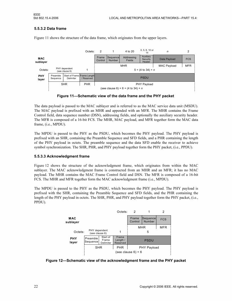
IEEEStd 802.15.4-2006 LOCAL AND METROPOLITAN AREA NETWORKS—PART 15.4:
5.5.3.2 Data frame
Figure 11 shows the structure of the data frame, which originates from the upper layers.
The data payload is passed to the MAC sublayer and is referred to as the MAC service data unit (MSDU).The MAC payload is prefixed with an MHR and appended with an MFR. The MHR contains the FrameControl field, data sequence number (DSN), addressing fields, and optionally the auxiliary security header.The MFR is composed of a 16-bit FCS. The MHR, MAC payload, and MFR together form the MAC dataframe, (i.e., MPDU).
The MPDU is passed to the PHY as the PSDU, which becomes the PHY payload. The PHY payload isprefixed with an SHR, containing the Preamble Sequence and SFD fields, and a PHR containing the lengthof the PHY payload in octets. The preamble sequence and the data SFD enable the receiver to achievesymbol synchronization. The SHR, PHR, and PHY payload together form the PHY packet, (i.e., PPDU).
5.5.3.3 Acknowledgment frame
Figure 12 shows the structure of the acknowledgment frame, which originates from within the MACsublayer. The MAC acknowledgment frame is constructed from an MHR and an MFR; it has no MACpayload. The MHR contains the MAC Frame Control field and DSN. The MFR is composed of a 16-bitFCS. The MHR and MFR together form the MAC acknowledgment frame (i.e., MPDU).
The MPDU is passed to the PHY as the PSDU, which becomes the PHY payload. The PHY payload isprefixed with the SHR, containing the Preamble Sequence and SFD fields, and the PHR containing thelength of the PHY payload in octets. The SHR, PHR, and PHY payload together form the PHY packet, (i.e.,PPDU).
Figure 11—Schematic view of the data frame and the PHY packet
PHY layer
Data Payload
MAC Payload
n
FCS
MFR
2
Sequence Number
1 4 to 20
Addressing Fields
2
Frame Control
MHR
PSDU
PHY Payload
5 + (4 to 34) + n
Frame Length / Reserved
1
PHR (see clause 6) + 6 + (4 to 34) + n
Start of Frame Delimiter
Preamble Sequence
MAC sublayer
PHY dependent (see clause 6)
SHR
Octets:
Octets:
0, 5, 6, 10 or 14
Auxiliary Security Header
Figure 12—Schematic view of the acknowledgment frame and the PHY packet
PHY layer
2
MHR MFR
1
Frame Control
PSDU
PHY Payload
5
(see clause 6) + 6
Preamble Sequence
MAC sublayer
1 Frame
Length / Reserved
SHR
PHY dependent (see clause 6)
PHR
Sequence Number
FCS
2
Start of Frame
Delimiter
Octets:
Octets:
22 Copyright © 2006 IEEE. All rights reserved.

IEEEWIRELESS MAC AND PHY SPECIFICATIONS FOR LR-WPANS Std 802.15.4-2006
5.5.3.4 MAC command frame
Figure 13 shows the structure of the MAC command frame, which originates from within the MACsublayer. The MAC payload contains the Command Type field and the command payload (see 7.2.2.4). TheMAC payload is prefixed with an MHR and appended with an MFR. The MHR contains the MAC FrameControl field, DSN, addressing fields, and optionally the auxiliary security header. The MFR contains a 16-bit FCS. The MHR, MAC payload, and MFR together form the MAC command frame, (i.e., MPDU).
The MPDU is then passed to the PHY as the PSDU, which becomes the PHY payload. The PHY payload isprefixed with an SHR, containing the Preamble Sequence and SFD fields, and a PHR containing the lengthof the PHY payload in octets. The preamble sequence enables the receiver to achieve symbolsynchronization. The SHR, PHR, and PHY payload together form the PHY packet, (i.e., PPDU).
5.5.4 Improving probability of successful delivery
The IEEE 802.15.4 LR-WPAN employs various mechanisms to improve the probability of successful datatransmission. These mechanisms are the CSMA-CA mechanism, frame acknowledgment, and dataverification and are briefly discussed in 5.5.4.1 through 5.5.4.3.
5.5.4.1 CSMA-CA mechanism
The IEEE 802.15.4 LR-WPAN uses two types of channel access mechanism, depending on the networkconfiguration. Nonbeacon-enabled PANs use an unslotted CSMA-CA channel access mechanism, asdescribed in 7.5.1. Each time a device wishes to transmit data frames or MAC commands, it waits for arandom period. If the channel is found to be idle, following the random backoff, the device transmits its data.If the channel is found to be busy following the random backoff, the device waits for another random periodbefore trying to access the channel again. Acknowledgment frames are sent without using a CSMA-CAmechanism.
Beacon-enabled PANs use a slotted CSMA-CA channel access mechanism, where the backoff slots arealigned with the start of the beacon transmission. The backoff slots of all devices within one PAN arealigned to the PAN coordinator. Each time a device wishes to transmit data frames during the CAP, it locatesthe boundary of the next backoff slot and then waits for a random number of backoff slots. If the channel isbusy, following this random backoff, the device waits for another random number of backoff slots beforetrying to access the channel again. If the channel is idle, the device begins transmitting on the next availablebackoff slot boundary. Acknowledgment and beacon frames are sent without using a CSMA-CAmechanism.
Figure 13—Schematic view of the MAC command frame and the PHY packet
PHY layer
MAC Payload
n
FCS
MFR
2
Sequence Number
1 4 to 20
Addressing Fields
2
Frame Control
MHR
PSDU
PHY Payload
6 + (4 to 34) + n Frame
Length / Reserved
1
PHR (see clause 6) + 7 + (4 to 34) + n
Preamble Sequence
MAC sublayer
PHY dependent (see clause 6)
SHR
Command Type
Command Payload
1
Start of Frame
Delimiter
Octets:
Octets:
Auxiliary Security Header
0, 5, 6, 10, or 14
Copyright © 2006 IEEE. All rights reserved. 23
IEEEStd 802.15.4-2006 LOCAL AND METROPOLITAN AREA NETWORKS—PART 15.4:
5.5.4.2 Frame acknowledgment
A successful reception and validation of a data or MAC command frame can be optionally confirmed withan acknowledgment, as described in 7.5.6.4. If the receiving device is unable to handle the received dataframe for any reason, the message is not acknowledged.
If the originator does not receive an acknowledgment after some period, it assumes that the transmission wasunsuccessful and retries the frame transmission. If an acknowledgment is still not received after severalretries, the originator can choose either to terminate the transaction or to try again. When theacknowledgment is not required, the originator assumes the transmission was successful.
5.5.4.3 Data verification
In order to detect bit errors, an FCS mechanism employing a 16-bit International TelecommunicationUnion—Telecommunication Standardization Sector (ITU-T) cyclic redundancy check (CRC) is used todetect errors in every frame.
The FCS mechanism is discussed in 7.2.1.9.
5.5.5 Power consumption considerations
In many applications that use this standard, devices will be battery powered, and battery replacement orrecharging in relatively short intervals is impractical. Therefore, the power consumption is of significantconcern. This standard was developed with limited power supply availability in mind. However, thephysical implementation of this standard will require additional power management considerations that arebeyond the scope of this standard.
The protocol has been developed to favor battery-powered devices. However, in certain applications, someof these devices could potentially be mains powered. Battery-powered devices will require duty-cycling toreduce power consumption. These devices will spend most of their operational life in a sleep state; however,each device periodically listens to the RF channel in order to determine whether a message is pending. Thismechanism allows the application designer to decide on the balance between battery consumption andmessage latency. Higher powered devices have the option of listening to the RF channel continuously.
5.5.6 Security
From a security perspective, wireless ad hoc networks are no different from any other wireless network.They are vulnerable to passive eavesdropping attacks and potentially even active tampering becausephysical access to the wire is not required to participate in communications. The very nature of ad hocnetworks and their cost objectives impose additional security constraints, which perhaps make thesenetworks the most difficult environments to secure. Devices are low-cost and have limited capabilities interms of computing power, available storage, and power drain; and it cannot always be assumed they have atrusted computing base nor a high-quality random number generator aboard. Communications cannot relyon the online availability of a fixed infrastructure and might involve short-term relationships betweendevices that may never have communicated before. These constraints might severely limit the choice ofcryptographic algorithms and protocols and would influence the design of the security architecture becausethe establishment and maintenance of trust relationships between devices need to be addressed with care. Inaddition, battery lifetime and cost constraints put severe limits on the security overhead these networks cantolerate, something that is of far less concern with higher bandwidth networks. Most of these securityarchitectural elements can be implemented at higher layers and may, therefore, be considered to be outsidethe scope of this standard.
The cryptographic mechanism in this standard is based on symmetric-key cryptography and uses keys thatare provided by higher layer processes. The establishment and maintenance of these keys are outside the
24 Copyright © 2006 IEEE. All rights reserved.
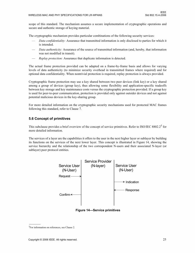
IEEEWIRELESS MAC AND PHY SPECIFICATIONS FOR LR-WPANS Std 802.15.4-2006
scope of this standard. The mechanism assumes a secure implementation of cryptographic operations andsecure and authentic storage of keying material.
The cryptographic mechanism provides particular combinations of the following security services:— Data confidentiality: Assurance that transmitted information is only disclosed to parties for which it
is intended.— Data authenticity: Assurance of the source of transmitted information (and, hereby, that information
was not modified in transit).— Replay protection: Assurance that duplicate information is detected.
The actual frame protection provided can be adapted on a frame-by-frame basis and allows for varyinglevels of data authenticity (to minimize security overhead in transmitted frames where required) and foroptional data confidentiality. When nontrivial protection is required, replay protection is always provided.
Cryptographic frame protection may use a key shared between two peer devices (link key) or a key sharedamong a group of devices (group key), thus allowing some flexibility and application-specific tradeoffsbetween key storage and key maintenance costs versus the cryptographic protection provided. If a group keyis used for peer-to-peer communication, protection is provided only against outsider devices and not againstpotential malicious devices in the key-sharing group.
For more detailed information on the cryptographic security mechanisms used for protected MAC framesfollowing this standard, refer to Clause 7.
5.6 Concept of primitives
This subclause provides a brief overview of the concept of service primitives. Refer to ISO/IEC 8802.25 formore detailed information.
The services of a layer are the capabilities it offers to the user in the next higher layer or sublayer by buildingits functions on the services of the next lower layer. This concept is illustrated in Figure 14, showing theservice hierarchy and the relationship of the two correspondent N-users and their associated N-layer (orsublayer) peer protocol entities.
5For information on references, see Clause 2.
Figure 14—Service primitives
Service Provider(N-layer)Service User
(N-User)Service User
(N-User)Request
Indication
ResponseConfirm
Copyright © 2006 IEEE. All rights reserved. 25

IEEEStd 802.15.4-2006 LOCAL AND METROPOLITAN AREA NETWORKS—PART 15.4:
The services are specified by describing the information flow between the N-user and the N-layer. Thisinformation flow is modeled by discrete, instantaneous events, which characterize the provision of a service.Each event consists of passing a service primitive from one layer to the other through a layer SAP associatedwith an N-user. Service primitives convey the required information by providing a particular service. Theseservice primitives are an abstraction because they specify only the provided service rather than the means bywhich it is provided. This definition is independent of any other interface implementation.
A service is specified by describing the service primitives and parameters that characterize it. A service mayhave one or more related primitives that constitute the activity that is related to that particular service. Eachservice primitive may have zero or more parameters that convey the information required to provide theservice.
A primitive can be one of four generic types:— Request: The request primitive is passed from the N-user to the N-layer to request that a service is
initiated.— Indication: The indication primitive is passed from the N-layer to the N-user to indicate an internal
N-layer event that is significant to the N-user. This event may be logically related to a remoteservice request, or it may be caused by an N-layer internal event.
— Response: The response primitive is passed from the N-user to the N-layer to complete a procedurepreviously invoked by an indication primitive.
— Confirm: The confirm primitive is passed from the N-layer to the N-user to convey the results of oneor more associated previous service requests.
26 Copyright © 2006 IEEE. All rights reserved.
IEEEWIRELESS MAC AND PHY SPECIFICATIONS FOR LR-WPANS Std 802.15.4-2006
6. PHY specification
6.1 General requirements and definitions
The PHY is responsible for the following tasks:— Activation and deactivation of the radio transceiver— Energy detection (ED) within the current channel— Link quality indicator (LQI) for received packets— Clear channel assessment (CCA) for carrier sense multiple access with collision avoidance
(CSMA-CA)— Channel frequency selection— Data transmission and reception
Constants and attributes that are specified and maintained by the PHY are written in the text of this clausein italics. Constants have a general prefix of “a”, e.g., aMaxPHYPacketSize, and are listed in Table 22(in 6.4.1). Attributes have a general prefix of “phy”, e.g., phyCurrentChannel, and are listed in Table 23 (in6.4.2).
This subclause specifies requirements that are common to all of the PHYs that conform to this standard.
The standard specifies the following four PHYs: — An 868/915 MHz direct sequence spread spectrum (DSSS) PHY employing binary phase-shift
keying (BPSK) modulation— An 868/915 MHz DSSS PHY employing offset quadrature phase-shift keying (O-QPSK)
modulation— An 868/915 MHz parallel sequence spread spectrum (PSSS) PHY employing BPSK and amplitude
shift keying (ASK) modulation— A 2450 MHz DSSS PHY employing O-QPSK modulation
In addition to the 868/915 MHz BPSK PHY, which was originally specified in the 2003 edition of thisstandard, two optional high-data-rate PHYs are specified for the 868/915 MHz bands, offering atradeoff between complexity and data rate. Both optional PHYs offer a data rate much higher than that of the868/915 MHz BPSK PHY, which provides for 20 kb/s in the 868 MHz band and 40 kb/s in the 915 MHzband. The ASK6 PHY offers data rates of 250 kb/s in both the 868 MHz and 915 MHz bands, which is equalto that of the 2.4 GHz band PHY. The O-QPSK PHY, which offers a signaling scheme identical to that ofthe 2.4 GHz band PHY, offers a data rate in the 915 MHz band equal to that of the 2.4 GHz band PHY and adata rate of 100 kb/s in the 868 MHz band.
6.1.1 Operating frequency range
A compliant device shall operate in one or several frequency bands using the modulation and spreadingformats summarized in Table 1.
Devices shall start in the mode (PHY) they are instructed to do so. If the device is capable of operating in the868/915 MHz bands using one of the optional PHYs, it shall be able to switch dynamically between theoptional 868/915 MHz band PHY and the mandatory 868/915 MHz BPSK PHYs when instructed to do so.
6The 868/915 MHz band ASK PHYs use BPSK modulation for the SHR and ASK modulation for the remainder of the PPDU.
Copyright © 2006 IEEE. All rights reserved. 27

IEEEStd 802.15.4-2006 LOCAL AND METROPOLITAN AREA NETWORKS—PART 15.4:
This standard is intended to conform with established regulations in Europe, Japan, Canada, and the UnitedStates. The regulatory documents listed below are for information only and are subject to change andrevisions at any time. Devices conforming to this standard shall also comply with specific regionallegislation. Additional regulatory information is provided in Annex F.
Europe:
— Approval standards: European Telecommunications Standards Institute (ETSI)
— Documents: ETSI EN 300 328-1 [B26], ETSI EN 300 328-2 [B27], ETSI EN 300 220-1 [B25],ERC Recommendation 70-03 [B24]
— Approval authority: National type approval authorities
Japan:
— Approval standards: Association of Radio Industries and Businesses (ARIB)
— Document: ARIB STD-T66 [B22]
— Approval authority: Ministry of Public Management, Home Affairs, Posts and Telecommunications(MPHPT)
United States:
— Approval standards: Federal Communications Commission (FCC), United States
— Document: FCC CFR47, Section 15.247 [B29]
Canada:
— Approval standards: Industry Canada (IC), Canada
— Document: GL36 [B32]
6.1.2 Channel assignments
The introduction of the “868/915 MHz band (optional) amplitude shift keying (ASK) PHY specifications”and “868/915 MHz band (optional) O-QPSK PHY specifications” results in the total number of channelassignments exceeding the channel numbering capability of 32 channel numbers that was defined in the2003 edition of this standard.
Table 1—Frequency bands and data rates
PHY(MHz)
Frequency band
(MHz)
Spreading parameters Data parameters
Chip rate (kchip/s) Modulation Bit rate
(kb/s)Symbol rate (ksymbol/s) Symbols
868/915868–868.6 300 BPSK 20 20 Binary
902–928 600 BPSK 40 40 Binary
868/915(optional)
868–868.6 400 ASK 250 12.5 20-bit PSSS
902–928 1600 ASK 250 50 5-bit PSSS
868/915(optional)
868–868.6 400 O-QPSK 100 25 16-ary Orthogonal
902–928 1000 O-QPSK 250 62.5 16-ary Orthogonal
2450 2400–2483.5 2000 O-QPSK 250 62.5 16-ary Orthogonal
28 Copyright © 2006 IEEE. All rights reserved.

IEEEWIRELESS MAC AND PHY SPECIFICATIONS FOR LR-WPANS Std 802.15.4-2006
To support the growing number of channels, channel assignments shall be defined through a combination ofchannel numbers and channels pages.
The upper 5 most significant bits (MSBs) of the 32-bit channel bitmaps in phyChannelsSupported shall beused as an integer value to specify 32 possible channel pages. The lower 27 bits of the channel bit map shallbe used as a bit mask to specify channel numbers within a channel page.
6.1.2.1 Channel numbering
A total of 27 channels numbered 0 to 26 are available per channel page.
For channel page 0, 27 channels numbered 0 to 26 are available across the three frequency bands. Sixteenchannels are available in the 2450 MHz band, 10 in the 915 MHz band, and 1 in the 868 MHz band. Thischannel page supports the channels defined in the 2003 edition of this standard. The center frequency ofthese channels is defined as follows:
Fc = 868.3 in megahertz, for k = 0
Fc = 906 + 2 (k – 1) in megahertz, for k = 1, 2, …, 10
and Fc = 2405 + 5 (k – 11) in megahertz, for k = 11, 12, …, 26
wherek is the channel number.
For channel pages 1 and 2, 11 channels numbered 0 to 10 are available across the two frequency bands tosupport the 868/915 MHz ASK and O-QPSK PHYs, respectively. Ten channels are available in the915 MHz band and 1 in the 868 MHz band. The center frequency of these channels is defined as follows:
Fc = 868.3 in megahertz, for k = 0
and Fc = 906 + 2 (k – 1) in megahertz, for k = 1, 2, …, 10
wherek is the channel number.
For each PHY supported, a compliant device shall support all channels allowed by regulations for the regionin which the device operates.
6.1.2.2 Channel pages
A total of 32 channel pages are available with channel pages 3 to 31 being reserved for future use. ThephyPagesSupported PHY PAN information base (PIB) attribute indicates which channel pages aresupported by the current PHY, while the phyCurrentPage PHY PIB attribute identifies the channel page thatis currently used. The PHY PIB attributes are described in 6.4.2.
If the requested PHY PIB attribute is the phyCurrentPage, the attribute was successfully set to a differentvalue from the current value, and the channel is no longer valid, then the PHY shall also set thephyCurrentChannel to the lowest valid channel for the requested page.
The channel pages and associated channel numbers are shown in Table 2.
Copyright © 2006 IEEE. All rights reserved. 29

IEEEStd 802.15.4-2006 LOCAL AND METROPOLITAN AREA NETWORKS—PART 15.4:
For example, the bitmap for channel 4 of channel page 2 would be as follows:
0 0 0 1 0 0 0 0 0 0 0 0 0 0 0 0 0 0 0 0 0 0 0 0 0 0 0 1 0 0 0 0
6.1.3 Minimum long interframe spacing (LIFS) and short interframe spacing (SIFS) periods
The minimum LIFS and SIFS periods for each of the PHYs are shown in Table 3. The description, use, andillustration of LIFS and SIFS is shown in Figure 68 (in 7.5.1.3).
Table 2—Channel page and channel number
Channel page
(decimal)
Channel page(binary)
(b31, b30, b29, b28, b27)
Channel number(s)(decimal)
Channel number description
0 0 0 0 0 0
0 Channel 0 is in 868 MHz band using BPSK
1–10 Channels 1 to 10 are in 915 MHz band using BPSK
11–26 Channels 11 to 26 are in 2.4 GHz band using O-QPSK
1 0 0 0 0 1
0 Channel 0 is in 868 MHz band using ASK
1–10 Channels 1 to 10 are in 915 MHz band using ASK
11–26 Reserved
2 0 0 0 1 0
0 Channel 0 is in 868 MHz band using O-QPSK
1–10 Channels 1 to 10 are in 915 MHz band using O-QPSK
11–26 Reserved
3–31 0 0 0 1 1 - 1 1 1 1 reserved Reserved
Table 3—Minimum LIFS and SIFS period
PHY macMinLIFSPeriod macMinSIFSPeriod Units
868–868.6 MHz BPSK 40 12 Symbols
902–928 MHz BPSK 40 12 Symbols
868–868.6 MHz ASK 40 12 Symbols
902–928 MHz ASK 40 12 Symbols
868–868.6 MHz O-QPSK 40 12 Symbols
902–928 MHz O-QPSK 40 12 Symbols
2400–2483.5 MHz O-QPSK 40 12 Symbols
30 Copyright © 2006 IEEE. All rights reserved.

IEEEWIRELESS MAC AND PHY SPECIFICATIONS FOR LR-WPANS Std 802.15.4-2006
6.1.4 RF power measurement
Unless otherwise stated, all RF power measurements, either transmit or receive, shall be made at theappropriate transceiver to antenna connector. The measurements shall be made with equipment that is eithermatched to the impedance of the antenna connector or corrected for any mismatch. For devices without anantenna connector, the measurements shall be interpreted as effective isotropic radiated power (EIRP) (i.e., a0 dBi gain antenna), and any radiated measurements shall be corrected to compensate for the antenna gain inthe implementation.
6.1.5 Transmit power
The maximum transmit power shall conform with local regulations. Refer to Annex F for additionalinformation on regulatory limits. A compliant device shall have its nominal transmit power level indicatedby its PHY parameter, phyTransmitPower (see 6.4).
6.1.6 Out-of-band spurious emission
The out-of-band spurious emissions shall conform with local regulations. Refer to Annex F for additionalinformation on regulatory limits on out-of-band emissions.
6.1.7 Receiver sensitivity definitions
The receiver sensitivity definitions used throughout this standard are defined in Table 4.
6.2 PHY service specifications
The PHY provides an interface between the MAC sublayer and the physical radio channel, via the RFfirmware and RF hardware. The PHY conceptually includes a management entity called the PLME. Thisentity provides the layer management service interfaces through which layer management functions may beinvoked. The PLME is also responsible for maintaining a database of managed objects pertaining to thePHY. This database is referred to as the PHY PAN information base (PIB).
Figure 15 depicts the components and interfaces of the PHY.
The PHY provides two services, accessed through two SAPs: the PHY data service, accessed through thePHY data SAP (PD-SAP), and the PHY management service, accessed through the PLME-SAP.
Table 4—Receiver sensitivity definitions
Term Definition of term Conditions
Packet error rate (PER) Average fraction of transmitted packets that are not correctly received.
– Average measured over random PSDU data.
Receiver sensitivity Threshold input signal power that yields a specified PER.
– PSDU length = 20 octets.– PER < 1%.– Power measured at antenna terminals.– Interference not present.
Copyright © 2006 IEEE. All rights reserved. 31
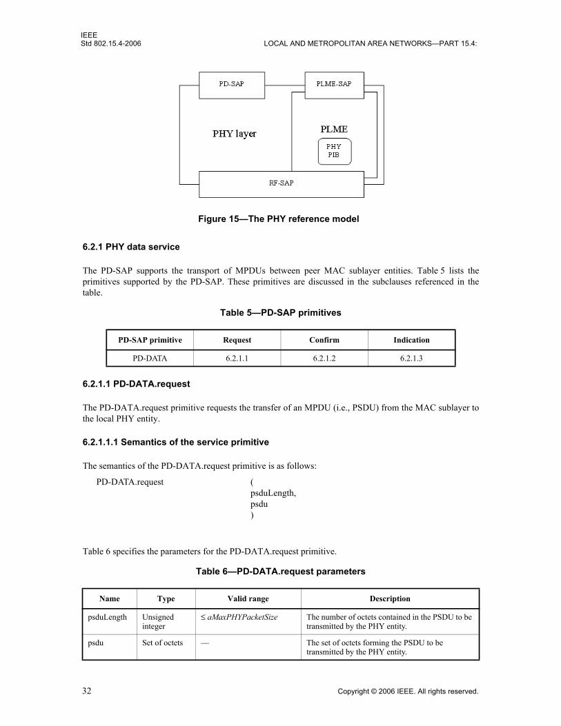
IEEEStd 802.15.4-2006 LOCAL AND METROPOLITAN AREA NETWORKS—PART 15.4:
6.2.1 PHY data service
The PD-SAP supports the transport of MPDUs between peer MAC sublayer entities. Table 5 lists theprimitives supported by the PD-SAP. These primitives are discussed in the subclauses referenced in thetable.
6.2.1.1 PD-DATA.request
The PD-DATA.request primitive requests the transfer of an MPDU (i.e., PSDU) from the MAC sublayer tothe local PHY entity.
6.2.1.1.1 Semantics of the service primitive
The semantics of the PD-DATA.request primitive is as follows:
Table 6 specifies the parameters for the PD-DATA.request primitive.
Table 5—PD-SAP primitives
PD-SAP primitive Request Confirm Indication
PD-DATA 6.2.1.1 6.2.1.2 6.2.1.3
Table 6—PD-DATA.request parameters
Name Type Valid range Description
psduLength Unsigned integer
≤ aMaxPHYPacketSize The number of octets contained in the PSDU to be transmitted by the PHY entity.
psdu Set of octets — The set of octets forming the PSDU to be transmitted by the PHY entity.
Figure 15—The PHY reference model
PD-DATA.request (psduLength,psdu)
32 Copyright © 2006 IEEE. All rights reserved.

IEEEWIRELESS MAC AND PHY SPECIFICATIONS FOR LR-WPANS Std 802.15.4-2006
6.2.1.1.2 Appropriate usage
The PD-DATA.request primitive is generated by a local MAC sublayer entity and issued to its PHY entity torequest the transmission of an MPDU.
6.2.1.1.3 Effect on receipt
The receipt of the PD-DATA.request primitive by the PHY entity will cause the transmission of the suppliedPSDU to be attempted. Provided the transmitter is enabled (TX_ON state), the PHY will first construct aPPDU, containing the supplied PSDU, and then transmit the PPDU. When the PHY entity has completed thetransmission, it will issue the PD-DATA.confirm primitive with a status of SUCCESS.
If the PD-DATA.request primitive is received while the receiver is enabled (RX_ON state), the PHY entitywill discard the PSDU and issue the PD-DATA.confirm primitive with a status of RX_ON. If thePD-DATA.request primitive is received while the transceiver is disabled (TRX_OFF state), the PHY entitywill discard the PSDU and issue the PD-DATA.confirm primitive with a status of TRX_OFF. If thePD-DATA.request primitive is received while the transmitter is already busy transmitting (BUSY_TXstate), the PHY entity will discard the PSDU and issue the PD-DATA.confirm primitive with a status ofBUSY_TX.
6.2.1.2 PD-DATA.confirm
The PD-DATA.confirm primitive confirms the end of the transmission of an MPDU (i.e., PSDU) from alocal PHY entity to a peer PHY entity.
6.2.1.2.1 Semantics of the service primitive
The semantics of the PD-DATA.confirm primitive is as follows:
Table 7 specifies the parameters for the PD-DATA.confirm primitive.
6.2.1.2.2 When generated
The PD-DATA.confirm primitive is generated by the PHY entity and issued to its MAC sublayer entity inresponse to a PD-DATA.request primitive. The PD-DATA.confirm primitive will return a status of eitherSUCCESS, indicating that the request to transmit was successful, or an error code of RX_ON, TRX_OFF, orBUSY_TX. The reasons for these status values are fully described in 6.2.1.1.3.
Table 7—PD-DATA.confirm parameters
Name Type Valid range Description
status Enumeration SUCCESS, RX_ON, TRX_OFF, or BUSY_TX
The result of the request to transmit a packet.
PD-DATA.confirm (status)
Copyright © 2006 IEEE. All rights reserved. 33

IEEEStd 802.15.4-2006 LOCAL AND METROPOLITAN AREA NETWORKS—PART 15.4:
6.2.1.2.3 Appropriate usage
On receipt of the PD-DATA.confirm primitive, the MAC sublayer entity is notified of the result of itsrequest to transmit. If the transmission attempt was successful, the status parameter is set to SUCCESS.Otherwise, the status parameter will indicate the error.
6.2.1.3 PD-DATA.indication
The PD-DATA.indication primitive indicates the transfer of an MPDU (i.e., PSDU) from the PHY to thelocal MAC sublayer entity.
6.2.1.3.1 Semantics of the service primitive
The semantics of the PD-DATA.indication primitive is as follows:
Table 8 specifies the parameters for the PD-DATA.indication primitive.
6.2.1.3.2 When generated
The PD-DATA.indication primitive is generated by the PHY entity and issued to its MAC sublayer entity totransfer a received PSDU. This primitive will not be generated if the received psduLength field is zero orgreater than aMaxPHYPacketSize.
6.2.1.3.3 Appropriate usage
On receipt of the PD-DATA.indication primitive, the MAC sublayer is notified of the arrival of an MPDUacross the PHY data service.
6.2.2 PHY management service
The PLME-SAP allows the transport of management commands between the MLME and the PLME.Table 9 lists the primitives supported by the PLME-SAP. These primitives are discussed in the clausesreferenced in the table.
Table 8—PD-DATA.indication parameters
Name Type Valid range Description
psduLength UnsignedInteger
≤ aMaxPHYPacketSize The number of octets contained in the PSDU received by the PHY entity.
psdu Set of octets — The set of octets forming the PSDU received by the PHY entity.
ppduLinkQuality Integer 0x00–0xff Link quality (LQI) value measured during reception of the PPDU (see 6.9.8).
PD-DATA.indication (psduLength,psdu,ppduLinkQuality)
34 Copyright © 2006 IEEE. All rights reserved.

IEEEWIRELESS MAC AND PHY SPECIFICATIONS FOR LR-WPANS Std 802.15.4-2006
6.2.2.1 PLME-CCA.request
The PLME-CCA.request primitive requests that the PLME perform a CCA as defined in 6.9.9.
6.2.2.1.1 Semantics of the service primitive
The semantics of the PLME-CCA.request primitive is as follows:
There are no parameters associated with the PLME-CCA.request primitive.
6.2.2.1.2 Appropriate usage
The PLME-CCA.request primitive is generated by the MLME and issued to its PLME whenever the CSMA-CA algorithm requires an assessment of the channel.
6.2.2.1.3 Effect on receipt
If the receiver is enabled on receipt of the PLME-CCA.request primitive, the PLME will cause the PHY toperform a CCA. When the PHY has completed the CCA, the PLME will issue the PLME-CCA.confirmprimitive with a status of either BUSY or IDLE, depending on the result of the CCA.
If the PLME-CCA.request primitive is received while the transceiver is disabled (TRX_OFF state) or if thetransmitter is enabled (TX_ON state), the PLME will issue the PLME-CCA.confirm primitive with a statusof TRX_OFF or BUSY, respectively.
6.2.2.2 PLME-CCA.confirm
The PLME-CCA.confirm primitive reports the results of a CCA as defined in 6.9.9.
6.2.2.2.1 Semantics of the service primitive
The semantics of the PLME-CCA.confirm primitive is as follows:
Table 10 specifies the parameters for the PLME-CCA.confirm primitive.
Table 9—PLME-SAP primitives
PLME-SAP primitive Request Confirm
PLME-CCA 6.2.2.1 6.2.2.2
PLME-ED 6.2.2.3 6.2.2.4
PLME-GET 6.2.2.5 6.2.2.6
PLME-SET-TRX-STATE 6.2.2.7 6.2.2.8
PLME-SET 6.2.2.9 6.2.2.10
PLME-CCA.request ()
PLME-CCA.confirm (status)
Copyright © 2006 IEEE. All rights reserved. 35
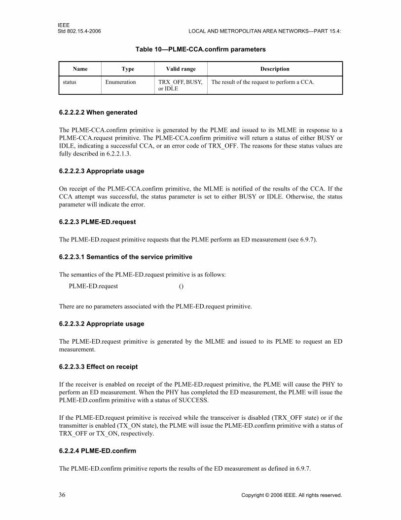
IEEEStd 802.15.4-2006 LOCAL AND METROPOLITAN AREA NETWORKS—PART 15.4:
6.2.2.2.2 When generated
The PLME-CCA.confirm primitive is generated by the PLME and issued to its MLME in response to aPLME-CCA.request primitive. The PLME-CCA.confirm primitive will return a status of either BUSY orIDLE, indicating a successful CCA, or an error code of TRX_OFF. The reasons for these status values arefully described in 6.2.2.1.3.
6.2.2.2.3 Appropriate usage
On receipt of the PLME-CCA.confirm primitive, the MLME is notified of the results of the CCA. If theCCA attempt was successful, the status parameter is set to either BUSY or IDLE. Otherwise, the statusparameter will indicate the error.
6.2.2.3 PLME-ED.request
The PLME-ED.request primitive requests that the PLME perform an ED measurement (see 6.9.7).
6.2.2.3.1 Semantics of the service primitive
The semantics of the PLME-ED.request primitive is as follows:
There are no parameters associated with the PLME-ED.request primitive.
6.2.2.3.2 Appropriate usage
The PLME-ED.request primitive is generated by the MLME and issued to its PLME to request an EDmeasurement.
6.2.2.3.3 Effect on receipt
If the receiver is enabled on receipt of the PLME-ED.request primitive, the PLME will cause the PHY toperform an ED measurement. When the PHY has completed the ED measurement, the PLME will issue thePLME-ED.confirm primitive with a status of SUCCESS.
If the PLME-ED.request primitive is received while the transceiver is disabled (TRX_OFF state) or if thetransmitter is enabled (TX_ON state), the PLME will issue the PLME-ED.confirm primitive with a status ofTRX_OFF or TX_ON, respectively.
6.2.2.4 PLME-ED.confirm
The PLME-ED.confirm primitive reports the results of the ED measurement as defined in 6.9.7.
Table 10—PLME-CCA.confirm parameters
Name Type Valid range Description
status Enumeration TRX_OFF, BUSY, or IDLE
The result of the request to perform a CCA.
PLME-ED.request ()
36 Copyright © 2006 IEEE. All rights reserved.

IEEEWIRELESS MAC AND PHY SPECIFICATIONS FOR LR-WPANS Std 802.15.4-2006
6.2.2.4.1 Semantics of the service primitive
The semantics of the PLME-ED.confirm primitive is as follows:
Table 11 specifies the parameters for the PLME-ED.confirm primitive.
6.2.2.4.2 When generated
The PLME-ED.confirm primitive is generated by the PLME and issued to its MLME in response to aPLME-ED.request primitive. The PLME-ED.confirm primitive will return a status of SUCCESS, indicatinga successful ED measurement, or an error code of TRX_OFF or TX_ON. The reasons for these status valuesare fully described in 6.2.2.3.3.
6.2.2.4.3 Appropriate usage
On receipt of the PLME-ED.confirm primitive, the MLME is notified of the results of the ED measurement.If the ED measurement attempt was successful, the status parameter is set to SUCCESS. Otherwise, thestatus parameter will indicate the error.
6.2.2.5 PLME-GET.request
The PLME-GET.request primitive requests information about a given PHY PIB attribute.
6.2.2.5.1 Semantics of the service primitive
The semantics of the PLME-GET.request primitive is as follows:
Table 12 specifies the parameters for the PLME-GET.request primitive.
Table 11—PLME-ED.confirm parameters
Name Type Valid range Description
status Enumeration SUCCESS, TRX_OFF, or TX_ON
The result of the request to perform an ED measurement.
EnergyLevel Integer0x00–0xff
ED level for the current channel. If status is set to SUCCESS, this is the ED level for the current channel. Otherwise, the value of this parameter will be ignored.
PLME-ED.confirm (status,EnergyLevel)
PLME-GET.request (PIBAttribute)
Copyright © 2006 IEEE. All rights reserved. 37

IEEEStd 802.15.4-2006 LOCAL AND METROPOLITAN AREA NETWORKS—PART 15.4:
6.2.2.5.2 Appropriate usage
The PLME-GET.request primitive is generated by the MLME and issued to its PLME to obtain informationfrom the PHY PIB.
6.2.2.5.3 Effect on receipt
On receipt of the PLME-GET.request primitive, the PLME will attempt to retrieve the requested PHY PIBattribute from its database. If the identifier of the PIB attribute is not found in the database, the PLME willissue the PLME-GET.confirm primitive with a status of UNSUPPORTED_ATTRIBUTE.
If the requested PHY PIB attribute is successfully retrieved, the PLME will issue the PLME-GET.confirmprimitive with a status of SUCCESS.
6.2.2.6 PLME-GET.confirm
The PLME-GET.confirm primitive reports the results of an information request from the PHY PIB.
6.2.2.6.1 Semantics of the service primitive
The semantics of the PLME-GET.confirm primitive is as follows:
Table 13 specifies the parameters for the PLME-GET.confirm primitive.
Table 12—PLME-GET.request parameters
Name Type Valid range Description
PIBAttribute Enumeration See Table 23 (in 6.4.2)
The identifier of the PHY PIB attribute to get.
Table 13—PLME-GET.confirm parameters
Name Type Valid range Description
status Enumeration SUCCESS or UNSUPPORTED_ATTRIBUTE
The result of the request for PHY PIB attribute information.
PIBAttribute Enumeration See Table 23 (in 6.4.2) The identifier of the PHY PIB attribute that was requested.
PIBAttributeValue Various Attribute specific The value of the indicated PHY PIB attribute that was requested. This parameter has zero length when the status parameter is set to UNSUPPORTED_ATTRIBUTE.
PLME-GET.confirm (status,PIBAttribute,PIBAttributeValue)
38 Copyright © 2006 IEEE. All rights reserved.
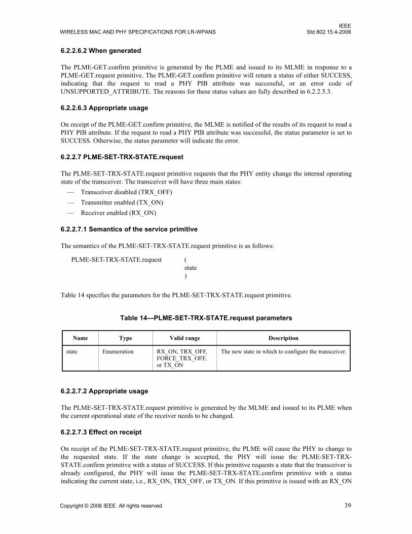
IEEEWIRELESS MAC AND PHY SPECIFICATIONS FOR LR-WPANS Std 802.15.4-2006
6.2.2.6.2 When generated
The PLME-GET.confirm primitive is generated by the PLME and issued to its MLME in response to aPLME-GET.request primitive. The PLME-GET.confirm primitive will return a status of either SUCCESS,indicating that the request to read a PHY PIB attribute was successful, or an error code ofUNSUPPORTED_ATTRIBUTE. The reasons for these status values are fully described in 6.2.2.5.3.
6.2.2.6.3 Appropriate usage
On receipt of the PLME-GET.confirm primitive, the MLME is notified of the results of its request to read aPHY PIB attribute. If the request to read a PHY PIB attribute was successful, the status parameter is set toSUCCESS. Otherwise, the status parameter will indicate the error.
6.2.2.7 PLME-SET-TRX-STATE.request
The PLME-SET-TRX-STATE.request primitive requests that the PHY entity change the internal operatingstate of the transceiver. The transceiver will have three main states:
— Transceiver disabled (TRX_OFF)— Transmitter enabled (TX_ON)— Receiver enabled (RX_ON)
6.2.2.7.1 Semantics of the service primitive
The semantics of the PLME-SET-TRX-STATE.request primitive is as follows:
Table 14 specifies the parameters for the PLME-SET-TRX-STATE.request primitive.
6.2.2.7.2 Appropriate usage
The PLME-SET-TRX-STATE.request primitive is generated by the MLME and issued to its PLME whenthe current operational state of the receiver needs to be changed.
6.2.2.7.3 Effect on receipt
On receipt of the PLME-SET-TRX-STATE.request primitive, the PLME will cause the PHY to change tothe requested state. If the state change is accepted, the PHY will issue the PLME-SET-TRX-STATE.confirm primitive with a status of SUCCESS. If this primitive requests a state that the transceiver isalready configured, the PHY will issue the PLME-SET-TRX-STATE.confirm primitive with a statusindicating the current state, i.e., RX_ON, TRX_OFF, or TX_ON. If this primitive is issued with an RX_ON
Table 14—PLME-SET-TRX-STATE.request parameters
Name Type Valid range Description
state Enumeration RX_ON, TRX_OFF, FORCE_TRX_OFF, or TX_ON
The new state in which to configure the transceiver.
PLME-SET-TRX-STATE.request (state)
Copyright © 2006 IEEE. All rights reserved. 39

IEEEStd 802.15.4-2006 LOCAL AND METROPOLITAN AREA NETWORKS—PART 15.4:
or TRX_OFF argument and the PHY is busy transmitting a PPDU, at the end of transmission the statechange will occur, and then the PHY will issue the PLME-SET-TRX-STATE.confirm primitive with astatus of SUCCESS. If this primitive is issued with TRX_OFF and the PHY is in RX_ON state and hasalready received a valid SFD, at the end of reception of the PPDU the state change will occur, and then thePHY will issue the PLME-SET-TRX-STATE.confirm primitive with a status SUCCESS. If this primitive isissued with TX_ON, the PHY will cause the PHY to go to the TX_ON state irrespective of the state the PHYis in. The PHY will then issue the PLME-SET-TRX-STATE.confirm primitive with a status SUCCESS. Ifthis primitive is issued with FORCE_TRX_OFF, the PHY will cause the PHY to go to the TRX_OFF stateirrespective of the state the PHY is in. The PHY will then issue the PLME-SET-TRX-STATE.confirmprimitive with a status SUCCESS.
6.2.2.8 PLME-SET-TRX-STATE.confirm
The PLME-SET-TRX-STATE.confirm primitive reports the result of a request to change the internaloperating state of the transceiver.
6.2.2.8.1 Semantics of the service primitive
The semantics of the PLME-SET-TRX-STATE.confirm primitive is as follows:
Table 15 specifies the parameters for the PLME-SET-TRX-STATE.confirm primitive.
6.2.2.8.2 When generated
The PLME-SET-TRX-STATE.confirm primitive is generated by the PLME and issued to its MLME afterattempting to change the internal operating state of the transceiver.
6.2.2.8.3 Appropriate usage
On receipt of the PLME-SET-TRX-STATE.confirm primitive, the MLME is notified of the result of itsrequest to change the internal operating state of the transceiver. A status value of SUCCESS indicates thatthe internal operating state of the transceiver was accepted. A status value of RX_ON, TRX_OFF, orTX_ON indicates that the transceiver is already in the requested internal operating state.
6.2.2.9 PLME-SET.request
The PLME-SET.request primitive attempts to set the indicated PHY PIB attribute to the given value.
Table 15—PLME-SET-TRX-STATE.confirm parameters
Name Type Valid range Description
status Enumeration SUCCESS, RX_ON, TRX_OFF, or TX_ON
The result of the request to change the state of the transceiver.
PLME-SET-TRX-STATE.confirm (status)
40 Copyright © 2006 IEEE. All rights reserved.

IEEEWIRELESS MAC AND PHY SPECIFICATIONS FOR LR-WPANS Std 802.15.4-2006
6.2.2.9.1 Semantics of the service primitive
The semantics of the PLME-SET.request primitive is as follows:
Table 16 specifies the parameters for the PLME-SET.request primitive.
6.2.2.9.2 Appropriate usage
The PLME-SET.request primitive is generated by the MLME and issued to its PLME to write the indicatedPHY PIB attribute.
6.2.2.9.3 Effect on receipt
On receipt of the PLME-SET.request primitive, the PLME will attempt to write the given value to theindicated PHY PIB attribute in its database. Not all PIB values are settable. If the PIBAttribute parameterspecifies an attribute that is not found in the database (see Table 23 in 6.4.2), the PLME will issue thePLME-SET.confirm primitive with a status of UNSUPPORTED_ATTRIBUTE. If the PIBAttributeparameter specifies an attribute whose value is read-only, the PLME will issue the PLME-SET.confirmprimitive with a status of READ_ONLY. If the PIBAttibuteValue parameter specifies a value that is out ofthe valid range for the given attribute, the PLME will issue the PLME-SET.confirm primitive with a statusof INVALID_PARAMETER.
If the requested PHY PIB attribute is successfully written, the PLME will issue the PLME-SET.confirmprimitive with a status of SUCCESS.
6.2.2.10 PLME-SET.confirm
The PLME-SET.confirm primitive reports the results of the attempt to set a PIB attribute.
6.2.2.10.1 Semantics of the service primitive
The semantics of the PLME-SET.confirm primitive is as follows:
Table 16—PLME-SET.request parameters
Name Type Valid range Description
PIBAttribute Enumeration See Table 23 (in 6.4.2)
The identifier of the PIB attribute to set.
PIBAttributeValue Various Attribute specific The value of the indicated PIB attribute to set.
PLME-SET.request (PIBAttribute,PIBAttributeValue)
PLME-SET.confirm (status,PIBAttribute)
Copyright © 2006 IEEE. All rights reserved. 41

IEEEStd 802.15.4-2006 LOCAL AND METROPOLITAN AREA NETWORKS—PART 15.4:
Table 17 specifies the parameters for the PLME-SET.confirm primitive.
6.2.2.10.2 When generated
The PLME-SET.confirm primitive is generated by the PLME and issued to its MLME in response to aPLME-SET.request primitive. The PLME-SET.confirm primitive will return a status of either SUCCESS,indicating that the requested value was written to the indicated PHY PIB attribute, or an error code ofUNSUPPORTED_ATTRIBUTE, INVALID_PARAMETER, or READ_ONLY. The reasons for thesestatus values are fully described in 6.2.2.9.3.
6.2.2.10.3 Appropriate usage
On receipt of the PLME-SET.confirm primitive, the MLME is notified of the result of its request to set thevalue of a PHY PIB attribute. If the requested value was written to the indicated PHY PIB attribute, thestatus parameter is set to SUCCESS. Otherwise, the status parameter will indicate the error.
6.2.3 PHY enumerations description
Table 18 shows a description of the PHY enumeration values defined in the PHY specification.
Table 17—PLME-SET.confirm parameters
Name Type Valid range Description
status Enumeration SUCCESS, UNSUPPORTED_ATTRIBUTE, INVALID_PARAMETER, or READ_ONLY
The status of the attempt to set the requested PIB attribute.
PIBAttribute Enumeration See Table 23 (in 6.4.2) The identifier of the PIB attribute being confirmed.
Table 18—PHY enumerations description
Enumeration Value Description
BUSY 0x00 The CCA attempt has detected a busy channel.
BUSY_RX 0x01 The transceiver is asked to change its state while receiving.
BUSY_TX 0x02 The transceiver is asked to change its state while transmitting.
FORCE_TRX_OFF 0x03 The transceiver is to be switched off immediately.
IDLE 0x04 The CCA attempt has detected an idle channel.
INVALID_PARAMETER 0x05 A SET/GET request was issued with a parameter in the primitive that is out of the valid range.
RX_ON 0x06 The transceiver is in or is to be configured into the receiver enabled state.
SUCCESS 0x07 A SET/GET, an ED operation, or a transceiver state change was successful.
42 Copyright © 2006 IEEE. All rights reserved.

IEEEWIRELESS MAC AND PHY SPECIFICATIONS FOR LR-WPANS Std 802.15.4-2006
6.3 PPDU format
This subclause specifies the format of the PPDU packet.
For convenience, the PPDU packet structure is presented so that the leftmost field as written in this standardshall be transmitted or received first. All multiple octet fields shall be transmitted or received leastsignificant octet first and each octet shall be transmitted or received least significant bit (LSB) first. Thesame transmission order should apply to data fields transferred between the PHY and MAC sublayer.
Each PPDU packet consists of the following basic components:— A synchronization header (SHR), which allows a receiving device to synchronize and lock onto the
bit stream— A PHY header (PHR), which contains frame length information— A variable length payload, which carries the MAC sublayer frame
The PPDU packet structure shall be formatted as illustrated in Figure 16.
6.3.1 Preamble field
The Preamble field is used by the transceiver to obtain chip and symbol synchronization with an incomingmessage. The length of the preamble for the different PHYs is shown in Table 19.
Preamble lengths for ASK are expressed in equivalent octet times as the preamble for ASK is defined usinga special symbol. For all PHYs except the ASK PHY, the bits in the Preamble field shall be binary zeros.The ASK preamble format is described in 6.7.4.1.
TRX_OFF 0x08 The transceiver is in or is to be configured into the transceiver disabled state.
TX_ON 0x09 The transceiver is in or is to be configured into the transmitter enabled state.
UNSUPPORTED_ATTRIBUTE 0x0a A SET/GET request was issued with the identifier of an attribute that is not supported.
READ_ONLY 0x0b A SET/GET request was issued with the identifier of an attribute that is read-only.
Octets
1 variable
Preamble SFD Frame length(7 bits)
Reserved(1 bit) PSDU
SHR PHR PHY payload
Figure 16—Format of the PPDU
Table 18—PHY enumerations description (continued)
Enumeration Value Description
Copyright © 2006 IEEE. All rights reserved. 43

IEEEStd 802.15.4-2006 LOCAL AND METROPOLITAN AREA NETWORKS—PART 15.4:
6.3.2 SFD field
The SFD is a field indicating the end of the SHR and the start of the packet data. The length of the SFD forthe different PHYs is shown in Table 20.
For all PHYs, except for the ASK PHY, the SFD is an 8-bit field. For the ASK PHY, the SFD is definedusing a special symbol. The lengths of the SFD for the ASK PHY are expressed in equivalent octet times.The SFD for all PHYs except the ASK PHY shall be formatted as illustrated in Figure 17. The SFD for theASK PHY is defined in 6.7.4.2.
Table 19—Preamble field length
PHY Length Duration (uS)
868–868.6 MHz BPSK 4 octets 32 symbols 1600
902–928 MHz BPSK 4 octets 32 symbols 800
868–868.6 MHz ASK 5 octets 2 symbols 160
902–928 MHz ASK 3.75 octets 6 symbols 120
868–868.6 MHz O-QPSK 4 octets 8 symbols 320
902–928 MHz O-QPSK 4 octets 8 symbols 128
2400–2483.5 MHz O-QPSK 4 octets 8 symbols 128
Table 20—SFD field length
PHY Length
868–868.6 MHz BPSK 1 octet 8 symbols
902–928 MHz BPSK 1 octet 8 symbols
868–868.6 MHz ASK 2.5 octets 1 symbol
902–928 MHz ASK 0.625 octets 1 symbol
868–868.6 MHz O-QPSK 1 octet 2 symbols
902–928 MHz O-QPSK 1 octet 2 symbols
2400–2483.5 MHz O-QPSK 1 octet 2 symbols
Bits: 0 1 2 3 4 5 6 7
1 1 1 0 0 1 0 1
Figure 17—Format of the SFD field (except for ASK)
44 Copyright © 2006 IEEE. All rights reserved.
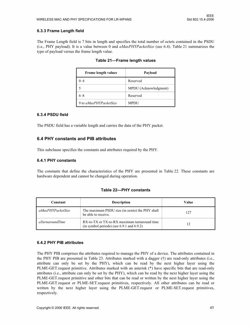
IEEEWIRELESS MAC AND PHY SPECIFICATIONS FOR LR-WPANS Std 802.15.4-2006
6.3.3 Frame Length field
The Frame Length field is 7 bits in length and specifies the total number of octets contained in the PSDU(i.e., PHY payload). It is a value between 0 and aMaxPHYPacketSize (see 6.4). Table 21 summarizes thetype of payload versus the frame length value.
6.3.4 PSDU field
The PSDU field has a variable length and carries the data of the PHY packet.
6.4 PHY constants and PIB attributes
This subclause specifies the constants and attributes required by the PHY.
6.4.1 PHY constants
The constants that define the characteristics of the PHY are presented in Table 22. These constants arehardware dependent and cannot be changed during operation.
6.4.2 PHY PIB attributes
The PHY PIB comprises the attributes required to manage the PHY of a device. The attributes contained inthe PHY PIB are presented in Table 23. Attributes marked with a dagger (†) are read-only attributes (i.e.,attribute can only be set by the PHY), which can be read by the next higher layer using thePLME-GET.request primitive. Attributes marked with an asterisk (*) have specific bits that are read-onlyattributes (i.e., attribute can only be set by the PHY), which can be read by the next higher layer using thePLME-GET.request primitive and other bits that can be read or written by the next higher layer using thePLME-GET.request or PLME-SET.request primitives, respectively. All other attributes can be read orwritten by the next higher layer using the PLME-GET.request or PLME-SET.request primitives,respectively.
Table 21—Frame length values
Frame length values Payload
0–4 Reserved
5 MPDU (Acknowledgment)
6–8 Reserved
9 to aMaxPHYPacketSize MPDU
Table 22—PHY constants
Constant Description Value
aMaxPHYPacketSize The maximum PSDU size (in octets) the PHY shall be able to receive. 127
aTurnaroundTime RX-to-TX or TX-to-RX maximum turnaround time (in symbol periods) (see 6.9.1 and 6.9.2) 12
Copyright © 2006 IEEE. All rights reserved. 45

IEEEStd 802.15.4-2006 LOCAL AND METROPOLITAN AREA NETWORKS—PART 15.4:
Table 23—PHY PIB attributes
Attribute Identifier Type Range Description
phyCurrentChannel 0x00 Integer 0–26 The RF channel to use for all follow-ing transmissions and receptions (see 6.1.2).
phyChannelsSupported† 0x01 Array An R x 32 bit array, where R ranges from 1 to 32
The array is composed of R rows, each of which is a bit string with the following properties: The 5 MSBs (b27, …, b31) indicate the channel page, and the 27 LSBs (b0, b1, …, b26) indicate the status (1=available, 0=unavailable) for each of the up to 27 valid channels (bk shall indicate the status of channel k as in 6.1.2) supported by that channel page. The device only needs to add the rows (channel pages) for the PHY(s) it supports.
phyTransmitPower* 0x02 Bitmap 0x00–0xbf The 2 MSBs represent the tolerance on the transmit power:00 = ± 1 dB01 = ± 3 dB10 = ± 6 dBand shall be read-only.The 6 LSBs, which may be written to, represent a signed integer in twos-complement format, corre-sponding to the nominal transmit power of the device in decibels rela-tive to 1 mW. The lowest value of phyTransmitPower is interpreted as less than or equal to –32 dBm.
phyCCAMode 0x03 Integer 1–3 The CCA mode (see 6.9.9).
phyCurrentPage 0x04 Integer 0–31 This is the current PHY channel page. This is used in conjunction with phyCurrentChannel to uniquely identify the channel currently being used.
phyMaxFrameDuration† 0x05 Integer 55, 212, 266, 1064
The maximum number of symbols in a frame: = phySHRDuration +ceiling([aMaxPHYPacketSize + 1] x phySymbolsPerOctet)
phySHRDuration† 0x06 Integer 3, 7, 10, 40 The duration of the synchronization header (SHR) in symbols for the cur-rent PHY.
phySymbolsPerOctet† 0x07 Float 0.4, 1.6, 2, 8
The number of symbols per octet for the current PHY.
46 Copyright © 2006 IEEE. All rights reserved.
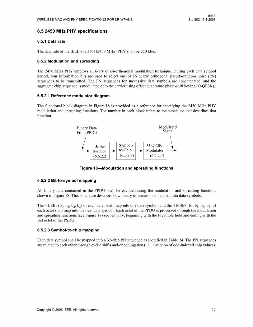
IEEEWIRELESS MAC AND PHY SPECIFICATIONS FOR LR-WPANS Std 802.15.4-2006
6.5 2450 MHz PHY specifications
6.5.1 Data rate
The data rate of the IEEE 802.15.4 (2450 MHz) PHY shall be 250 kb/s.
6.5.2 Modulation and spreading
The 2450 MHz PHY employs a 16-ary quasi-orthogonal modulation technique. During each data symbolperiod, four information bits are used to select one of 16 nearly orthogonal pseudo-random noise (PN)sequences to be transmitted. The PN sequences for successive data symbols are concatenated, and theaggregate chip sequence is modulated onto the carrier using offset quadrature phase-shift keying (O-QPSK).
6.5.2.1 Reference modulator diagram
The functional block diagram in Figure 18 is provided as a reference for specifying the 2450 MHz PHYmodulation and spreading functions. The number in each block refers to the subclause that describes thatfunction.
6.5.2.2 Bit-to-symbol mapping
All binary data contained in the PPDU shall be encoded using the modulation and spreading functionsshown in Figure 18. This subclause describes how binary information is mapped into data symbols.
The 4 LSBs (b0, b1, b2, b3) of each octet shall map into one data symbol, and the 4 MSBs (b4, b5, b6, b7) ofeach octet shall map into the next data symbol. Each octet of the PPDU is processed through the modulationand spreading functions (see Figure 18) sequentially, beginning with the Preamble field and ending with thelast octet of the PSDU.
6.5.2.3 Symbol-to-chip mapping
Each data symbol shall be mapped into a 32-chip PN sequence as specified in Table 24. The PN sequencesare related to each other through cyclic shifts and/or conjugation (i.e., inversion of odd-indexed chip values).
Figure 18—Modulation and spreading functions
Bit-to-Symbol to-Chip
O-QPSKModulator
Binary DataFrom PPDU
ModulatedSignal
(6.5.2.2) (6.5.2.3) (6.5.2.4)
Symbol-
Copyright © 2006 IEEE. All rights reserved. 47

IEEEStd 802.15.4-2006 LOCAL AND METROPOLITAN AREA NETWORKS—PART 15.4:
6.5.2.4 O-QPSK modulation
The chip sequences representing each data symbol are modulated onto the carrier using O-QPSK with half-sine pulse shaping. Even-indexed chips are modulated onto the in-phase (I) carrier and odd-indexed chipsare modulated onto the quadrature-phase (Q) carrier. Because each data symbol is represented by a 32-chipsequence, the chip rate (nominally 2.0 Mchip/s) is 32 times the symbol rate. To form the offset betweenI-phase and Q-phase chip modulation, the Q-phase chips shall be delayed by Tc with respect to the I-phasechips (see Figure 19), where Tc is the inverse of the chip rate.
Table 24—Symbol-to-chip mapping
Data symbol(decimal)
Data symbol(binary)
(b0 b1 b2 b3)
Chip values(c0 c1 … c30 c31)
0 0 0 0 0 1 1 0 1 1 0 0 1 1 1 0 0 0 0 1 1 0 1 0 1 0 0 1 0 0 0 1 0 1 1 1 0
1 1 0 0 0 1 1 1 0 1 1 0 1 1 0 0 1 1 1 0 0 0 0 1 1 0 1 0 1 0 0 1 0 0 0 1 0
2 0 1 0 0 0 0 1 0 1 1 1 0 1 1 0 1 1 0 0 1 1 1 0 0 0 0 1 1 0 1 0 1 0 0 1 0
3 1 1 0 0 0 0 1 0 0 0 1 0 1 1 1 0 1 1 0 1 1 0 0 1 1 1 0 0 0 0 1 1 0 1 0 1
4 0 0 1 0 0 1 0 1 0 0 1 0 0 0 1 0 1 1 1 0 1 1 0 1 1 0 0 1 1 1 0 0 0 0 1 1
5 1 0 1 0 0 0 1 1 0 1 0 1 0 0 1 0 0 0 1 0 1 1 1 0 1 1 0 1 1 0 0 1 1 1 0 0
6 0 1 1 0 1 1 0 0 0 0 1 1 0 1 0 1 0 0 1 0 0 0 1 0 1 1 1 0 1 1 0 1 1 0 0 1
7 1 1 1 0 1 0 0 1 1 1 0 0 0 0 1 1 0 1 0 1 0 0 1 0 0 0 1 0 1 1 1 0 1 1 0 1
8 0 0 0 1 1 0 0 0 1 1 0 0 1 0 0 1 0 1 1 0 0 0 0 0 0 1 1 1 0 1 1 1 1 0 1 1
9 1 0 0 1 1 0 1 1 1 0 0 0 1 1 0 0 1 0 0 1 0 1 1 0 0 0 0 0 0 1 1 1 0 1 1 1
10 0 1 0 1 0 1 1 1 1 0 1 1 1 0 0 0 1 1 0 0 1 0 0 1 0 1 1 0 0 0 0 0 0 1 1 1
11 1 1 0 1 0 1 1 1 0 1 1 1 1 0 1 1 1 0 0 0 1 1 0 0 1 0 0 1 0 1 1 0 0 0 0 0
12 0 0 1 1 0 0 0 0 0 1 1 1 0 1 1 1 1 0 1 1 1 0 0 0 1 1 0 0 1 0 0 1 0 1 1 0
13 1 0 1 1 0 1 1 0 0 0 0 0 0 1 1 1 0 1 1 1 1 0 1 1 1 0 0 0 1 1 0 0 1 0 0 1
14 0 1 1 1 1 0 0 1 0 1 1 0 0 0 0 0 0 1 1 1 0 1 1 1 1 0 1 1 1 0 0 0 1 1 0 0
15 1 1 1 1 1 1 0 0 1 0 0 1 0 1 1 0 0 0 0 0 0 1 1 1 0 1 1 1 1 0 1 1 1 0 0 0
c0 c2 c4 c30. . .I-Phase
Q-Phase
Tc
2Tc
c1 c3 c5 c31. . .
Figure 19—O-QPSK chip offsets
48 Copyright © 2006 IEEE. All rights reserved.
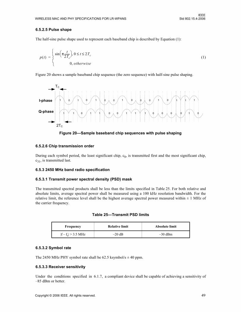
IEEEWIRELESS MAC AND PHY SPECIFICATIONS FOR LR-WPANS Std 802.15.4-2006
6.5.2.5 Pulse shape
The half-sine pulse shape used to represent each baseband chip is described by Equation (1):
(1)
Figure 20 shows a sample baseband chip sequence (the zero sequence) with half-sine pulse shaping.
6.5.2.6 Chip transmission order
During each symbol period, the least significant chip, c0, is transmitted first and the most significant chip,c31, is transmitted last.
6.5.3 2450 MHz band radio specification
6.5.3.1 Transmit power spectral density (PSD) mask
The transmitted spectral products shall be less than the limits specified in Table 25. For both relative andabsolute limits, average spectral power shall be measured using a 100 kHz resolution bandwidth. For therelative limit, the reference level shall be the highest average spectral power measured within ± 1 MHz ofthe carrier frequency.
6.5.3.2 Symbol rate
The 2450 MHz PHY symbol rate shall be 62.5 ksymbol/s ± 40 ppm.
6.5.3.3 Receiver sensitivity
Under the conditions specified in 6.1.7, a compliant device shall be capable of achieving a sensitivity of–85 dBm or better.
Table 25—Transmit PSD limits
Frequency Relative limit Absolute limit
|f – fc| > 3.5 MHz –20 dB –30 dBm
p t( )π t
2Tc--------⎝ ⎠
⎛ ⎞sin 0 t 2Tc≤ ≤,
0 otherwise,⎩⎪⎨⎪⎧
=
Figure 20—Sample baseband chip sequences with pulse shaping
1 0 1 0
1 1 0 1
I-phase
Q-phase
1 0 0 1
1 0 0 1
0 0 0
1 1 0 0
1 0 1 1
0 0 1 0
1
TC
2TC
Copyright © 2006 IEEE. All rights reserved. 49

IEEEStd 802.15.4-2006 LOCAL AND METROPOLITAN AREA NETWORKS—PART 15.4:
6.5.3.4 Receiver jamming resistance
The minimum jamming resistance levels are given in Table 26. The adjacent channel is one on either side ofthe desired channel that is closest in frequency to the desired channel, and the alternate channel is one moreremoved from the adjacent channel. For example, when channel 13 is the desired channel, channel 12 andchannel 14 are the adjacent channels, and channel 11 and channel 15 are the alternate channels.
The adjacent channel rejection shall be measured as follows: the desired signal shall be a compliant2450 MHz IEEE 802.15.4 O-QPSK PHY signal, as defined by 6.5.2, of pseudo-random data. The desiredsignal is input to the receiver at a level 3 dB above the maximum allowed receiver sensitivity given in6.5.3.3.
In either the adjacent or the alternate channel, an IEEE 802.15.4 signal, as defined by 6.5.2, is input at therelative level specified in Table 26. The test shall be performed for only one interfering signal at a time. Thereceiver shall meet the error rate criteria defined in 6.1.7 under these conditions.
6.6 868/915 MHz band binary phase-shift keying (BPSK) PHY specifications
6.6.1 868/915 MHz band data rates
The data rate of the 868/915 MHz band BPSK PHY shall be 20 kb/s when operating in the 868 MHz bandand 40 kb/s when operating in the 915 MHz band.
6.6.2 Modulation and spreading
The 868/915 MHz BPSK PHY shall employ direct sequence spread spectrum (DSSS) with BPSK used forchip modulation and differential encoding used for data symbol encoding.
6.6.2.1 Reference modulator diagram
The functional block diagram in Figure 21 is provided as a reference for specifying the 868/915 MHz bandBPSK PHY modulation and spreading functions. The number in each block refers to the subclause thatdescribes that function. Each bit in the PPDU shall be processed through the differential encoding, bit-to-chip mapping and modulation functions in octet-wise order, beginning with the Preamble field and endingwith the last octet of the PSDU. Within each octet, the LSB, b0, is processed first and the MSB, b7, isprocessed last.
Table 26—Minimum receiver jamming resistance requirements for 2450 MHz PHY
Adjacent channelrejection
Alternate channel rejection
0 dB 30 dB
Figure 21—Modulation and spreading functions
Bit-to-Chip
DifferentialEncoder
BPSKModulator
Binary Data ModulatedSignal
(6.6.2.3)(6.6.2.2) (6.6.2.4)From PPDU
50 Copyright © 2006 IEEE. All rights reserved.

IEEEWIRELESS MAC AND PHY SPECIFICATIONS FOR LR-WPANS Std 802.15.4-2006
6.6.2.2 Differential encoding
Differential encoding is the modulo-2 addition (exclusive or) of a raw data bit with the previous encoded bit.This is performed by the transmitter and can be described by Equation (2):
(2)
where Rn is the raw data bit being encodedEn is the corresponding differentially encoded bitEn–1 is the previous differentially encoded bit
For each packet transmitted, R1 is the first raw data bit to be encoded and E0 is assumed to be zero.
Conversely, the decoding process, as performed at the receiver, can be described by Equation (3):
(3)
For each packet received, E1 is the first bit to be decoded, and E0 is assumed to be zero.
6.6.2.3 Bit-to-chip mapping
Each input bit shall be mapped into a 15-chip PN sequence as specified in Table 27.
6.6.2.4 BPSK modulation
The chip sequences are modulated onto the carrier using BPSK with raised cosine pulse shaping (roll-offfactor = 1) where a chip value of one corresponds to a positive pulse and a chip value of zero corresponds toa negative pulse. The chip rate is 300 kchip/s for the 868 MHz band and 600 kchip/s in the 915 MHz band.
6.6.2.4.1 Pulse shape
The raised cosine pulse shape (roll-off factor = 1) used to represent each baseband chip is described byEquation (4):
(4)
Table 27—Symbol-to-chip mapping
Input bits Chip values(c0 c1 … c14)
0 1 1 1 1 0 1 0 1 1 0 0 1 0 0 0
1 0 0 0 0 1 0 1 0 0 1 1 0 1 1 1
En Rn En 1–⊕=
Rn En En 1–⊕=
p t( )
πt Tc⁄sinπt Tc⁄
----------------------πt Tc⁄cos
1 4t2 Tc2⁄–
-------------------------- t 0≠,
1 t 0=,⎩⎪⎨⎪⎧
=
Copyright © 2006 IEEE. All rights reserved. 51
IEEEStd 802.15.4-2006 LOCAL AND METROPOLITAN AREA NETWORKS—PART 15.4:
6.6.2.4.2 Chip transmission order
During each symbol period, the least significant chip, c0, is transmitted first, and the most significant chip,c15, is transmitted last.
6.6.3 868/915 MHz band radio specification
6.6.3.1 Operating frequency range
The 868/915 MHz BPSK PHY operates in the 868.0–868.6 MHz frequency band and in the 902–928 MHzfrequency band.
6.6.3.2 915 MHz band transmit PSD mask
The transmitted spectral products shall be less than the limits specified in Table 28. For both relative andabsolute limits, average spectral power shall be measured using a 100 kHz resolution bandwidth. For therelative limit, the reference level shall be the highest average spectral power measured within ± 600 kHz ofthe carrier frequency.
6.6.3.3 Symbol rate
The symbol rate of an 868/915 MHz BPSK PHY conforming to this standard shall be 20 ksymbol/s whenoperating in the 868 MHz band and 40 ksymbol/s when operating in the 915 MHz band with an accuracy of± 40 ppm.
6.6.3.4 Receiver sensitivity
Under the conditions specified in 6.1.7, a compliant device shall be capable of achieving a sensitivity of–92 dBm or better.
6.6.3.5 Receiver jamming resistance
This subclause applies only to the 902–928 MHz band as there is only one channel available in the 868.0–868.6 MHz band.
The minimum jamming resistance levels are given in Table 29. The adjacent channel is one on either side ofthe desired channel that is closest in frequency to the desired channel, and the alternate channel is one moreremoved from the adjacent channel. For example, when channel 5 is the desired channel, channel 4 andchannel 6 are the adjacent channels, and channel 3 and channel 7 are the alternate channels.
Table 28—915 MHz band transmit PSD limits
Frequency Relative limit Absolute limit
|f – fc| > 1.2 MHz –20 dB –20 dBm
52 Copyright © 2006 IEEE. All rights reserved.

IEEEWIRELESS MAC AND PHY SPECIFICATIONS FOR LR-WPANS Std 802.15.4-2006
The adjacent channel rejection shall be measured as follows: the desired signal shall be a compliant915 MHz IEEE 802.15.4 BPSK PHY signal, as defined by 6.6.2, of pseudo-random data. The desired signalis input to the receiver at a level 3 dB above the maximum allowed receiver sensitivity given in 6.6.3.4.
In either the adjacent or the alternate channel, a compliant IEEE 802.15.4 signal, as defined by 6.6.2, is inputat the relative level specified in Table 29. The test shall be performed for only one interfering signal at atime. The receiver shall meet the error rate criteria defined in 6.1.7 under these conditions.
6.7 868/915 MHz band (optional) amplitude shift keying (ASK) PHY specifications
6.7.1 868/915 MHz band data rates
The data rate of the ASK PHY shall be 250 kb/s when operating in the 868 MHz band and in the 915 MHzband. The ASK PHY is not mandatory in the 868/915 MHz band. If the ASK PHY is used in the 868/915 MHz band, then the same device shall be capable of signaling using the 868/915 MHz BPSK PHY aswell.
6.7.2 Modulation and spreading
The ASK PHY employs a multi-code modulation technique named parallel sequence spread spectrum(PSSS), which is also more generically known as orthogonal code division multiplexing (OCDM). Duringeach data symbol period, 20 information bits for 868 MHz and 5 information bits for 915 MHz areseparately modulated onto 20 and 5 nearly orthogonal PN sequences, respectively. The 20 for 868 MHz and5 for 915 MHz PN sequences are linearly summed to create a multi-level 32-chip symbol, equal to a 64-half-chip symbol for 868 MHz and a multi-level 32-chip symbol for 915 MHz. A simple precoding is thenexecuted per symbol, and the resulting multi-level 64-half-chip sequence for 868 MHz and multi-level32-chip sequence for 915 MHz are modulated onto the carrier using ASK.
6.7.2.1 Reference modulator diagram
The functional block diagram in Figure 22 is provided as a reference for specifying the PSSS modulationand spreading functions. The number in each block refers to the subclause that describes that function.
Table 29—Minimum receiver jamming resistance requirements for 915 MHz PHY
Adjacent channelrejection
Alternate channel rejection
0 dB 30 dB
Figure 22—Modulation and spreading functions
Bit-to-Symbol
ASKModulatorPHY header,
ModulatedSignal
(6.7.2.2) (6.7.2.4)PHY payload
BPSKModulator(6.7.4)
Symbol-to-Chip
(6.7.2.3)
Binary DataSHR
Binary Data
Copyright © 2006 IEEE. All rights reserved. 53

IEEEStd 802.15.4-2006 LOCAL AND METROPOLITAN AREA NETWORKS—PART 15.4:
Each octet of the PPDU is sequentially processed through the spreading and modulation functions. Thesynchronization header shall be encoded using the BPSK modulator, and the PHY header and PHY payloadshall be processed using the bit-to-symbol mapping, and symbol-to-chip spreading and the ASK modulatoras shown in Figure 22.
6.7.2.2 Bit-to-symbol mapping
The first 20 bits for 868 MHz and the first 5 bits for 915 MHz, starting with the LSB (b0) of the first octet ofthe PHY header and continuing with the subsequent octet of the PHY header, shall be mapped into the firstdata symbol. Further 20 bits for 868 MHz and further 5 bits for 915 MHz continuing until the end of thePPDU shall be mapped sequentially to each subsequent data symbol until all octets of the PHY header andPHY payload have been mapped into symbols, always mapping the LSBs of any octet first. For eachsymbol, the least significant chip shall be the first chip transmitted over the air. The last input bits shall befollowed by padding, with “0” bits, of its high order bits to fill out the symbol. These zero pad bits will alsobe spread via the PSSS encoding to keep the over the air signaling as random as possible.
6.7.2.3 Symbol-to-chip mapping
Each data symbol shall be mapped into a multi-level 64-half-chip symbol for 868 MHz and a multi-level32-chip symbol for 915 MHz as described in this subclause. Figure 23 provides an overview of the symbol-to-chip mapping.
Each bit of the data stream is multiplied with its corresponding sequence of the code table defined inTable 30 for 868 MHz and Table 31 for 915 MHz. The PSSS code tables were generated by selecting 20 for868 MHz and 5 for 915 MHz cyclically shifted sequences of a 31-chip base sequence and then adding a 1-bitcyclic extension to each sequence. For 868 MHz PSSS, the 31-chip base sequence is cyclically shifted by1.5 chips to generate the next sequence in the table. For 915 MHz PSSS, the 31-chip base sequence iscyclically shifted by 6 chips to generate the next sequence in the table.
The vector of bits comprising the data symbol is multiplied with the PSSS code table. In other words, bit b0of the data symbol is multiplied with sequence number “0”, bit b1 is multiplied with sequence number “1”,etc. Prior to multiplication, the data bits are converted to bipolar levels: data bit “1” becomes +1 and databit “0” becomes –1. The result of multiplication is a modulated code table, which is similar to Table 30 orTable 31, but with each row either inverted or not according to the data bits.
Subsequently, all rows of the modulated code table are linearly summed to create a multi-level 64-half-chipsymbol for 868 MHz and multi-level 32-chip symbol for 915 MHz. For example, chip 0 of the multi-level
Figure 23—Symbol-to-chip mapping for PHY header and PHY payload
54 Copyright © 2006 IEEE. All rights reserved.

IEEEWIRELESS MAC AND PHY SPECIFICATIONS FOR LR-WPANS Std 802.15.4-2006
sequence is produced by linearly summing chip 0 from each of the modulated sequences. The per-columnresults are 32 chips c0…c31 for 915 MHz and 64 half-chips c0…c63 for 868 MHz.
Next, a precoding operation is applied to the multi-level 32-chip symbol for 915 MHz and the multi-level64-half-chip symbol for 868 MHz. The precoding is independent from one symbol to the next, and isperformed in two steps. In the first step, a constant value is added to each of the 32 chips for 915 MHz and64 half-chips for 868 MHz. The constant is selected so that the minimum and maximum values of theresulting sequence are symmetric about zero. Representing the original multi-level 32-chip symbol sequenceby p(m), then the modified sequence p'(m) after step one of precoding is as shown in Equation (5).
(5)
In the second step, a scaling constant is multiplied by each chip for 915 MHz and half-chip for 868 MHz inp'(m). The scaling constant is selected such that the resulting sequence has a maximum amplitude of one.Letting p"(m) be the output of the second precoding step, then
(6)
where Max' is the maximum within p'(m). See also example in 6.7.4.3.
The precoded sequence of 32 multi-level chips for 915 MHz and 64 multi-value half-chips for 868 MHz ismodulated onto the carrier as described in 6.7.2.4.
6.7.2.4 ASK modulation
The chip sequences representing each data symbol are modulated onto the carrier using ASK with squareroot raised cosine pulse shaping. The chip rate is 400 kchip/s, equal to 800 khalf-chip/s for 868 MHz. Thechip rate is 1600 kchip/s for 915 MHz.
6.7.2.4.1 Pulse shape
The root-raised-cosine pulse shape used to represent each baseband chip is described by Equation (7).
(7)
with a rolloff factor r = 0.2 for 868 MHz and 915 MHz. The pulse for stimulating the pulse shaping filterwill be generated at chip rate/half chip rate for 915/868 MHz. Tc in Equation (7) is the chip duration (nothalf chip) for 868 MHz and 915 MHz.
6.7.2.4.2 Chip transmission order
During each symbol period, the least significant chip/half-chip, c0 / hc0, is transmitted first, and the mostsignificant chip, c31 / hc63, is transmitted last.
p ' m( ) p m( ) Max Min+( )2
---------------------------------–=
p'' m( ) p' m( )Max'-------------=
h t( )
π r 1+( ) π4--- r 1+( )
r----------------⎝ ⎠
⎛ ⎞sin⋅ π r 1–( ) π4--- r 1–( )
r----------------⎝ ⎠
⎛ ⎞cos⋅ 4r π4--- r 1–( )
r----------------⎝ ⎠
⎛ ⎞sin⋅–+⎩ ⎭⎨ ⎬⎧ ⎫
2π Tc
------------------------------------------------------------------------------------------------------------------------------------------------------------------------------------- t Tc 4r( )⁄±( )=,
4rπ Tc
------------- r 1–( )Tc
----------------– t, 0=
4r1 r+( )πt Tc⁄( ) 1 r–( )πt Tc⁄( ) 4rt Tc⁄( )⁄sin+cos
π Tc 1 4rt Tc⁄( )2–( )-------------------------------------------------------------------------------------------------------------------------- t 0 and ≠ t Tc 4r( )⁄±( )≠,
⎩⎪⎪⎪⎪⎪⎨⎪⎪⎪⎪⎪⎧
=
Copyright © 2006 IEEE. All rights reserved. 55

IEEEStd 802.15.4-2006 LOCAL AND METROPOLITAN AREA NETWORKS—PART 15.4:
Tabl
e 30
—PS
SS c
ode
tabl
e us
ed in
sym
bol-t
o-ch
ip m
appi
ng fo
r 868
MH
z
Tabl
e 31
—PS
SS c
ode
tabl
e us
ed in
sym
bol-t
o-ch
ip m
appi
ng fo
r 915
MH
z
56 Copyright © 2006 IEEE. All rights reserved.

IEEEWIRELESS MAC AND PHY SPECIFICATIONS FOR LR-WPANS Std 802.15.4-2006
6.7.3 868/915 MHz band radio specification for the ASK PHY
6.7.3.1 Operating frequency range
The 868/915 MHz ASK PHY operates in the 868.0–868.6 MHz frequency band and in the 902–928 MHzfrequency band.
6.7.3.2 915 MHz band transmit PSD mask
The transmitted spectral products shall be less than the limits specified in Table 32. For both relative andabsolute limits, average spectral power shall be measured using a 100 kHz resolution bandwidth. For therelative limit, the reference level shall be the highest average spectral power measured within ± 600 kHz ofthe carrier frequency.
6.7.3.3 Symbol rate
The ASK PHY symbol rate shall be 12.5 ksymbol/s ± 40 ppm for 868 MHz and 50 ksymbol/s ± 40 ppm for915 MHz.
6.7.3.4 Receiver sensitivity
Under the conditions specified in 6.1.7, a compliant device shall be capable of achieving a sensitivity of–85 dBm or better.
6.7.3.5 Receiver jamming resistance
This subclause applies only to the 902–928 MHz band as there is only one channel available in the 868.0–868.6 MHz band.
The minimum jamming resistance levels are given in Table 33. The adjacent channel is one on either side ofthe desired channel that is closest in frequency to the desired channel, and the alternate channel is one moreremoved from the adjacent channel. For example, when channel 5 is the desired channel, channel 4 andchannel 6 are the adjacent channels, and channel 3 and channel 7 are the alternate channels.
The adjacent channel rejection shall be measured as follows: the desired signal shall be a compliant915 MHz IEEE 802.15.4 ASK PHY signal, as defined by 6.7.2, of pseudo-random data. The desired signalis input to the receiver at a level 3 dB above the maximum allowed receiver sensitivity given in 6.7.3.4.
Table 32—915 MHz band ASK PHY transmit PSD limits
Frequency Relative limit Absolute limit
|f – fc| > 1.2 MHz –20 dB –20 dBm
Table 33—Minimum receiver jamming resistance requirements for 915 MHz ASK PHY
Adjacent channelrejection
Alternate channel rejection
0 dB 30 dB
Copyright © 2006 IEEE. All rights reserved. 57
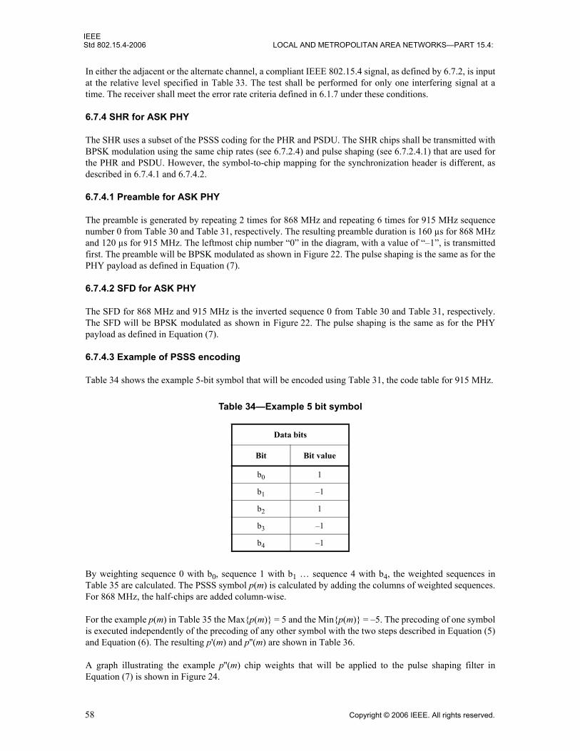
IEEEStd 802.15.4-2006 LOCAL AND METROPOLITAN AREA NETWORKS—PART 15.4:
In either the adjacent or the alternate channel, a compliant IEEE 802.15.4 signal, as defined by 6.7.2, is inputat the relative level specified in Table 33. The test shall be performed for only one interfering signal at atime. The receiver shall meet the error rate criteria defined in 6.1.7 under these conditions.
6.7.4 SHR for ASK PHY
The SHR uses a subset of the PSSS coding for the PHR and PSDU. The SHR chips shall be transmitted withBPSK modulation using the same chip rates (see 6.7.2.4) and pulse shaping (see 6.7.2.4.1) that are used forthe PHR and PSDU. However, the symbol-to-chip mapping for the synchronization header is different, asdescribed in 6.7.4.1 and 6.7.4.2.
6.7.4.1 Preamble for ASK PHY
The preamble is generated by repeating 2 times for 868 MHz and repeating 6 times for 915 MHz sequencenumber 0 from Table 30 and Table 31, respectively. The resulting preamble duration is 160 µs for 868 MHzand 120 µs for 915 MHz. The leftmost chip number “0” in the diagram, with a value of “–1”, is transmittedfirst. The preamble will be BPSK modulated as shown in Figure 22. The pulse shaping is the same as for thePHY payload as defined in Equation (7).
6.7.4.2 SFD for ASK PHY
The SFD for 868 MHz and 915 MHz is the inverted sequence 0 from Table 30 and Table 31, respectively.The SFD will be BPSK modulated as shown in Figure 22. The pulse shaping is the same as for the PHYpayload as defined in Equation (7).
6.7.4.3 Example of PSSS encoding
Table 34 shows the example 5-bit symbol that will be encoded using Table 31, the code table for 915 MHz.
By weighting sequence 0 with b0, sequence 1 with b1 … sequence 4 with b4, the weighted sequences inTable 35 are calculated. The PSSS symbol p(m) is calculated by adding the columns of weighted sequences.For 868 MHz, the half-chips are added column-wise.
For the example p(m) in Table 35 the Max{p(m)} = 5 and the Min{p(m)} = –5. The precoding of one symbolis executed independently of the precoding of any other symbol with the two steps described in Equation (5)and Equation (6). The resulting p'(m) and p''(m) are shown in Table 36.
A graph illustrating the example p''(m) chip weights that will be applied to the pulse shaping filter inEquation (7) is shown in Figure 24.
Table 34—Example 5 bit symbol
Data bits
Bit Bit value
b0 1
b1 –1
b2 1
b3 –1
b4 –1
58 Copyright © 2006 IEEE. All rights reserved.

IEEEWIRELESS MAC AND PHY SPECIFICATIONS FOR LR-WPANS Std 802.15.4-2006
Tabl
e 35
—W
eigh
ted
sequ
ence
s
Tabl
e 36
—p'
(m),
alig
ned
sym
met
ric to
zer
o PS
SS s
ymbo
l, an
d p'
'(m),
prec
oded
PSS
S sy
mbo
l
Figu
re 2
4—Pr
ecod
ed P
SSS
sym
bol p
''(m
)
Copyright © 2006 IEEE. All rights reserved. 59

IEEEStd 802.15.4-2006 LOCAL AND METROPOLITAN AREA NETWORKS—PART 15.4:
6.8 868/915 MHz band (optional) O-QPSK PHY specifications
6.8.1 868/915 MHz band data rates
The data rate of the O-QPSK PHY shall be 100 kb/s when operating in the 868 MHz band and 250 kb/swhen operating in the 915 MHz band. The O-QPSK PHY is not mandatory in the 868/915 MHz band. If theO-QPSK PHY is used in the 868/915 MHz band then the same device shall be capable of signaling using the868/915 MHz BPSK PHY as well.
6.8.2 Modulation and spreading
The O-QPSK PHY employs a 16-ary quasi-orthogonal modulation technique. During each data symbolperiod, four information bits are used to select one of 16 nearly orthogonal PN sequences to be transmitted.The PN sequences for successive data symbols are concatenated, and the aggregate chip sequence ismodulated onto the carrier using O-QPSK.
6.8.2.1 Reference modulator diagram
The functional block diagram in Figure 25 is provided as a reference for specifying the 868/915 MHz bandPHY modulation and spreading functions. The number in each block refers to the subclause that describesthat function. Each bit in the PPDU shall be processed through the bit-to-symbol mapping, symbol-to-chipmapping, and modulation functions in octet-wise order, beginning with the Preamble field and ending withthe last octet of the PSDU. Within each octet, the LSB, b0, is processed first and the MSB, b7, is processedlast.
6.8.2.2 Bit-to-symbol mapping
All binary data contained in the PPDU shall be encoded using the modulation and spreading functionsshown in Figure 25. This subclause describes how binary information is mapped into data symbols.
The 4 LSBs (b0, b1, b2, b3) of each octet shall map into one data symbol, and the 4 MSBs (b4, b5, b6, b7) ofeach octet shall map into the next data symbol. Each octet of the PPDU is processed through the modulationand spreading functions (see Figure 25) sequentially, beginning with the Preamble field and ending with thelast octet of the PSDU. Within each octet, the least significant symbol (b0, b1, b2, b3) is processed first, andthe most significant symbol (b4, b5, b6, b7) is processed second.
6.8.2.3 Symbol-to-chip mapping
Each data symbol shall be mapped into a 16-chip PN sequence as specified in Table 37.
Figure 25—Modulation and spreading functions
Bit-to-Symbol to-Chip
O-QPSKModulator
Binary DataFrom PPDU
ModulatedSignal
(6.8.2.2) (6.8.2.3) (6.8.2.4)
Symbol-
60 Copyright © 2006 IEEE. All rights reserved.

IEEEWIRELESS MAC AND PHY SPECIFICATIONS FOR LR-WPANS Std 802.15.4-2006
6.8.2.4 O-QPSK modulation
The chip sequences representing each data symbol are modulated onto the carrier using O-QPSK with half-sine pulse shaping. Even-indexed chips are modulated onto the in-phase (I) carrier and odd-indexed chipsare modulated onto the quadrature-phase (Q) carrier. Because each data symbol is represented by a 16-chipsequence, the chip rate (nominally 400 kchip/s and 1.0 Mchip/s for the 868 MHz and 915 MHz bands,respectively) is 16 times the symbol rate. To form the offset between I-phase and Q-phase chip modulation,the Q-phase chips shall be delayed by Tc with respect to the I-phase chips (see Figure 26), where Tc is theinverse of the chip rate.
Table 37—Symbol-to-chip mapping for O-QPSK
Data symbol(decimal)
Data symbol(binary)
(b0 b1 b2 b3)
Chip values(c0 c1 … c14 c15)
0 0 0 0 0 0 0 1 1 1 1 1 0 0 0 1 0 0 1 0 1
1 1 0 0 0 0 1 0 0 1 1 1 1 1 0 0 0 1 0 0 1
2 0 1 0 0 0 1 0 1 0 0 1 1 1 1 1 0 0 0 1 0
3 1 1 0 0 1 0 0 1 0 1 0 0 1 1 1 1 1 0 0 0
4 0 0 1 0 0 0 1 0 0 1 0 1 0 0 1 1 1 1 1 0
5 1 0 1 0 1 0 0 0 1 0 0 1 0 1 0 0 1 1 1 1
6 0 1 1 0 1 1 1 0 0 0 1 0 0 1 0 1 0 0 1 1
7 1 1 1 0 1 1 1 1 1 0 0 0 1 0 0 1 0 1 0 0
8 0 0 0 1 0 1 1 0 1 0 1 1 0 1 1 1 0 0 0 0
9 1 0 0 1 0 0 0 1 1 0 1 0 1 1 0 1 1 1 0 0
10 0 1 0 1 0 0 0 0 0 1 1 0 1 0 1 1 0 1 1 1
11 1 1 0 1 1 1 0 0 0 0 0 1 1 0 1 0 1 1 0 1
12 0 0 1 1 0 1 1 1 0 0 0 0 0 1 1 0 1 0 1 1
13 1 0 1 1 1 1 0 1 1 1 0 0 0 0 0 1 1 0 1 0
14 0 1 1 1 1 0 1 1 0 1 1 1 0 0 0 0 0 1 1 0
15 1 1 1 1 1 0 1 0 1 1 0 1 1 1 0 0 0 0 0 1
c0 c2 c4 c14. . .I-Phase
Q-Phase
Tc
2Tc
c1 c3 c5 c15. . .
Figure 26—O-QPSK chip offsets
Copyright © 2006 IEEE. All rights reserved. 61

IEEEStd 802.15.4-2006 LOCAL AND METROPOLITAN AREA NETWORKS—PART 15.4:
6.8.2.5 Pulse shape
The half-sine pulse shape used to represent each baseband chip is described by Equation (8).
(8)
Figure 27 shows a sample baseband chip sequence (the zero sequence) with half-sine pulse shaping.
6.8.2.6 Chip transmission order
During each symbol period, the least significant chip, c0, is transmitted first, and the most significant chip,c15, is transmitted last.
6.8.3 868/915 MHz band radio specification
6.8.3.1 Operating frequency range
The 868/915 MHz O-QPSK PHY operates in the 868.0–868.6 MHz frequency band and in the 902–928 MHz frequency band.
6.8.3.2 Transmit PSD mask
When operating in the 868 MHz band, the signal shall be filtered before transmission to regulate the transmitPSD. The filter shall approximate an ideal raised cosine filter with a roll-off factor r = 0.2, which is specifiedin Equation (9).
(9)
When operating in the 915 MHz band, the transmitted spectral products shall be less than the limits specifiedin Table 38. For both relative and absolute limits, average spectral power shall be measured using a 100 kHzresolution bandwidth. For the relative limit, the reference level shall be the highest average spectral powermeasured within ± 600 kHz of the carrier frequency fc.
p t( )π t
2Tc--------⎝ ⎠
⎛ ⎞sin 0 t 2Tc≤ ≤,
0 otherwise,⎩⎪⎨⎪⎧
=
Figure 27—Sample baseband chip sequences with pulse shaping
I-p h a s e
Q -p h a s e
T C
2 T C
0 1
0 0 1
0 0
1
0 1 1
0 1 0
1
1
p t( )
πt Tc⁄sinπt Tc⁄
----------------------rπt Tc⁄cos
1 4r2t2 Tc2⁄–
------------------------------- t 0≠,
1 t 0=,⎩⎪⎨⎪⎧
=
62 Copyright © 2006 IEEE. All rights reserved.

IEEEWIRELESS MAC AND PHY SPECIFICATIONS FOR LR-WPANS Std 802.15.4-2006
6.8.3.3 Symbol rate
The O-QPSK PHY symbol rate shall be 25 ksymbol/s when operating in the 868 MHz band and62.5 ksymbol/s when operating in the 915 MHz band with an accuracy of ± 40 ppm.
6.8.3.4 Receiver sensitivity
Under the conditions specified in 6.1.7, a compliant device shall be capable of achieving a sensitivity of–85 dBm or better.
6.8.3.5 Receiver jamming resistance
This subclause applies only to the 902–928 MHz band as there is only one channel available in the 868.0–868.6 MHz band.
The minimum jamming resistance levels are given in Table 39. The adjacent channel is one on either side ofthe desired channel that is closest in frequency to the desired channel, and the alternate channel is one moreremoved from the adjacent channel. For example, when channel 5 is the desired channel, channel 4 andchannel 6 are the adjacent channels, and channel 3 and channel 7 are the alternate channels.
The adjacent channel rejection shall be measured as follows: the desired signal shall be a compliant915 MHz IEEE 802.15.4 O-QPSK PHY signal, as defined by 6.8.2, of pseudo-random data. The desiredsignal is input to the receiver at a level 3 dB above the maximum allowed receiver sensitivity given in6.8.3.4.
In either the adjacent or the alternate channel, a compliant signal, as defined by 6.8.2, is input at the relativelevel specified in Table 39. The test shall be performed for only one interfering signal at a time. The receivershall meet the error rate criteria defined in 6.1.7 under these conditions.
6.9 General radio specifications
The specifications in 6.9.1 through 6.9.9 apply to both the 2450 MHz PHY and the 868/915 MHz PHYs and,with the exception of 6.9.3, apply to all PHY implementations including the alternate PHYs.
6.9.1 TX-to-RX turnaround time
The TX-to-RX turnaround time shall be less than or equal to aTurnaroundTime (see 6.4.1).
Table 38—915 MHz band O-QPSK PHY transmit PSD limits
Frequency Relative limit Absolute limit
|f – fc| > 1.2 MHz –20 dB –20 dBm
Table 39—Minimum receiver jamming resistance requirements for 915 MHz O-QPSK PHY
Adjacent channelrejection
Alternate channel rejection
0 dB 30 dB
Copyright © 2006 IEEE. All rights reserved. 63

IEEEStd 802.15.4-2006 LOCAL AND METROPOLITAN AREA NETWORKS—PART 15.4:
The TX-to-RX turnaround time is defined as the shortest time possible at the air interface from the trailingedge of the last chip (of the last symbol) of a transmitted PPDU to the leading edge of the first chip (of thefirst symbol) of the next received PPDU.
The TX-to-RX turnaround time shall be less than or equal to the RX-to-TX turnaround time.
6.9.2 RX-to-TX turnaround time
The RX-to-TX turnaround time shall be less than or equal to aTurnaroundTime (see 6.4.1).
The RX-to-TX turnaround time is defined as the shortest time possible at the air interface from the trailingedge of the last chip (of the last symbol) of a received PPDU to the leading edge of the first chip (of the firstsymbol) of the next transmitted PPDU.
6.9.3 Error-vector magnitude (EVM) definition
The modulation accuracy of the transmitter is determined with an EVM measurement. In order to calculatethe EVM measurement, a time record of N received complex chip values is captured. For eachreceived complex chip, a decision is made about which complex chip value was transmitted. The idealposition of the chosen complex chip (the center of the decision box) is represented by the vector .The error vector is defined as the distance from this ideal position to the actual position of thereceived point (see Figure 28).
Thus, the received vector is the sum of the ideal vector and the error vector as shown in Equation (10).
(10)
The EVM is defined as shown in Equation (11).
(11)
Ij Qj,( )
Ij Qj,( )δIj δQj,( )
Figure 28—Error vector calculation
Ij Qj,( )
Ij Qj,( )
δIj δQj,( )
I Channel Amplitude
Q C
hann
el A
mpl
itude
Ij Qj,( ) Ij Qj,( ) δIj δQj,( )+=
EVM
1N---- δIj
2 δQj2+( )
j 1=
N
∑
S2--------------------------------------------- × 100%≡
64 Copyright © 2006 IEEE. All rights reserved.

IEEEWIRELESS MAC AND PHY SPECIFICATIONS FOR LR-WPANS Std 802.15.4-2006
where S is the magnitude of the vector to the ideal constellation point (for PSSS in 915/868 MHz
S is the ASK step size, and the PHR and PHY payload should be set to 0 for testing)
is the error vector
A transmitter shall have EVM values of less than 35% when measured for 1000 chips. The error-vectormeasurement shall be made on baseband I and Q chips after recovery through a reference receiver system.The reference receiver shall perform carrier lock, symbol timing recovery, and amplitude adjustment whilemaking the measurements.
6.9.4 Transmit center frequency tolerance
The transmitted center frequency tolerance shall be ± 40 ppm maximum.
6.9.5 Transmit power
A transmitter shall be capable of transmitting at least –3 dBm. Devices should transmit lower power whenpossible in order to reduce interference to other devices and systems.
The maximum transmit power is limited by local regulatory bodies.
6.9.6 Receiver maximum input level of desired signal
The receiver maximum input level is the maximum power level of the desired signal present at the input ofthe receiver for which the error rate criterion in 6.1.7 is met. A receiver shall have a receiver maximum inputlevel greater than or equal to –20 dBm.
6.9.7 Receiver ED
The receiver ED measurement is intended for use by a network layer as part of a channel selectionalgorithm. It is an estimate of the received signal power within the bandwidth of the channel. No attempt ismade to identify or decode signals on the channel. The ED measurement time, to average over, shall beequal to 8 symbol periods.
The ED result shall be reported to the MLME using PLME-ED.confirm (see 6.2.2.4) as an 8 bit integerranging from 0x00 to 0xff. The minimum ED value (zero) shall indicate received power less than 10 dBabove the specified receiver sensitivity (see 6.5.3.3 and 6.6.3.4), and the range of received power spanned bythe ED values shall be at least 40 dB. Within this range, the mapping from the received power in decibels toED value shall be linear with an accuracy of ± 6 dB.
6.9.8 Link quality indicator (LQI)
The LQI measurement is a characterization of the strength and/or quality of a received packet. Themeasurement may be implemented using receiver ED, a signal-to-noise ratio estimation, or a combination ofthese methods. The use of the LQI result by the network or application layers is not specified in thisstandard.
The LQI measurement shall be performed for each received packet, and the result shall be reported to theMAC sublayer using PD-DATA.indication (see 6.2.1.3) as an integer ranging from 0x00 to 0xff. Theminimum and maximum LQI values (0x00 and 0xff) should be associated with the lowest and highestquality compliant signals detectable by the receiver, and LQI values in between should be uniformlydistributed between these two limits. At least eight unique values of LQI shall be used.
δIj δQj,( )
Copyright © 2006 IEEE. All rights reserved. 65

IEEEStd 802.15.4-2006 LOCAL AND METROPOLITAN AREA NETWORKS—PART 15.4:
6.9.9 Clear channel assessment (CCA)
The PHY shall provide the capability to perform CCA according to at least one of the following threemethods:
— CCA Mode 1: Energy above threshold. CCA shall report a busy medium upon detecting any energyabove the ED threshold.
— CCA Mode 2: Carrier sense only. CCA shall report a busy medium only upon the detection of asignal compliant with this standard with the same modulation and spreading characteristics of thePHY that is currently in use by the device. This signal may be above or below the ED threshold.
— CCA Mode 3: Carrier sense with energy above threshold. CCA shall report a busy medium using alogical combination of — Detection of a signal with the modulation and spreading characteristics of this standard and — Energy above the ED threshold, where the logical operator may be AND or OR.
For any of the CCA modes, if the PLME-CCA.request primitive (see 6.2.2.1) is received by the PHY duringreception of a PPDU, CCA shall report a busy medium. PPDU reception is considered to be in progressfollowing detection of the SFD, and it remains in progress until the number of octets specified by thedecoded PHR has been received.
A busy channel shall be indicated by the PLME-CCA.confirm primitive (see 6.2.2.2) with a status of BUSY.
A clear channel shall be indicated by the PLME-CCA.confirm primitive with a status of IDLE.
The PHY PIB attribute phyCCAMode (see 6.4) shall indicate the appropriate operation mode. The CCAparameters are subject to the following criteria:
a) The ED threshold shall correspond to a received signal power of at most 10 dB above the specifiedreceiver sensitivity (see 6.5.3.3, 6.6.3.4, 6.7.3.4, and 6.8.3.4).
b) The CCA detection time shall be equal to 8 symbol periods.
66 Copyright © 2006 IEEE. All rights reserved.
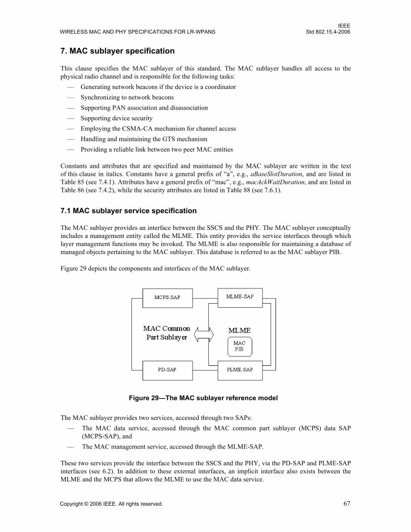
IEEEWIRELESS MAC AND PHY SPECIFICATIONS FOR LR-WPANS Std 802.15.4-2006
7. MAC sublayer specification
This clause specifies the MAC sublayer of this standard. The MAC sublayer handles all access to thephysical radio channel and is responsible for the following tasks:
— Generating network beacons if the device is a coordinator— Synchronizing to network beacons— Supporting PAN association and disassociation— Supporting device security— Employing the CSMA-CA mechanism for channel access— Handling and maintaining the GTS mechanism— Providing a reliable link between two peer MAC entities
Constants and attributes that are specified and maintained by the MAC sublayer are written in the textof this clause in italics. Constants have a general prefix of “a”, e.g., aBaseSlotDuration, and are listed inTable 85 (see 7.4.1). Attributes have a general prefix of “mac”, e.g., macAckWaitDuration, and are listed inTable 86 (see 7.4.2), while the security attributes are listed in Table 88 (see 7.6.1).
7.1 MAC sublayer service specification
The MAC sublayer provides an interface between the SSCS and the PHY. The MAC sublayer conceptuallyincludes a management entity called the MLME. This entity provides the service interfaces through whichlayer management functions may be invoked. The MLME is also responsible for maintaining a database ofmanaged objects pertaining to the MAC sublayer. This database is referred to as the MAC sublayer PIB.
Figure 29 depicts the components and interfaces of the MAC sublayer.
The MAC sublayer provides two services, accessed through two SAPs: — The MAC data service, accessed through the MAC common part sublayer (MCPS) data SAP
(MCPS-SAP), and — The MAC management service, accessed through the MLME-SAP.
These two services provide the interface between the SSCS and the PHY, via the PD-SAP and PLME-SAPinterfaces (see 6.2). In addition to these external interfaces, an implicit interface also exists between theMLME and the MCPS that allows the MLME to use the MAC data service.
Figure 29—The MAC sublayer reference model
Copyright © 2006 IEEE. All rights reserved. 67

IEEEStd 802.15.4-2006 LOCAL AND METROPOLITAN AREA NETWORKS—PART 15.4:
7.1.1 MAC data service
The MCPS-SAP supports the transport of SSCS protocol data units (SPDUs) between peer SSCS entities.Table 40 lists the primitives supported by the MCPS-SAP. Primitives marked with a diamond (♦) areoptional for an RFD. These primitives are discussed in the subclauses referenced in the table.
7.1.1.1 MCPS-DATA.request
The MCPS-DATA.request primitive requests the transfer of a data SPDU (i.e., MSDU) from a local SSCSentity to a single peer SSCS entity.
7.1.1.1.1 Semantics of the service primitive
The semantics of the MCPS-DATA.request primitive are as follows:
Table 41 specifies the parameters for the MCPS-DATA.request primitive.
Table 40—MCPS-SAP primitives
MCPS-SAP primitive Request Confirm Indication
MCPS-DATA 7.1.1.1 7.1.1.2 7.1.1.3
MCPS-PURGE 7.1.1.4♦ 7.1.1.5♦ —
Table 41—MCPS-DATA.request parameters
Name Type Valid range Description
SrcAddrMode Integer 0x00–0x03 The source addressing mode for this primitive andsubsequent MPDU. This value can take one of thefollowing values:0x00 = no address (addressing fields omitted, see7.2.1.1.8).0x01 = reserved.0x02 = 16-bit short address.0x03 = 64-bit extended address.
MCPS-DATA.request (SrcAddrMode,DstAddrMode,DstPANId,DstAddr,msduLength,msdu,msduHandle,TxOptions,SecurityLevel,KeyIdMode,KeySource,KeyIndex)
68 Copyright © 2006 IEEE. All rights reserved.
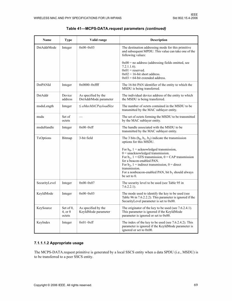
IEEEWIRELESS MAC AND PHY SPECIFICATIONS FOR LR-WPANS Std 802.15.4-2006
7.1.1.1.2 Appropriate usage
The MCPS-DATA.request primitive is generated by a local SSCS entity when a data SPDU (i.e., MSDU) isto be transferred to a peer SSCS entity.
DstAddrMode Integer 0x00–0x03 The destination addressing mode for this primitive and subsequent MPDU. This value can take one of the following values:
0x00 = no address (addressing fields omitted, see 7.2.1.1.6).0x01 = reserved.0x02 = 16-bit short address.0x03 = 64-bit extended address.
DstPANId Integer 0x0000–0xffff The 16-bit PAN identifier of the entity to which the MSDU is being transferred.
DstAddr Device address
As specified by the DstAddrMode parameter
The individual device address of the entity to which the MSDU is being transferred.
msduLength Integer ≤ aMaxMACPayloadSize The number of octets contained in the MSDU to be transmitted by the MAC sublayer entity.
msdu Set of octets
— The set of octets forming the MSDU to be transmitted by the MAC sublayer entity.
msduHandle Integer 0x00–0xff The handle associated with the MSDU to be transmitted by the MAC sublayer entity.
TxOptions Bitmap 3-bit field The 3 bits (b0, b1, b2) indicate the transmission options for this MSDU.
For b0, 1 = acknowledged transmission, 0 = unacknowledged transmission. For b1, 1 = GTS transmission, 0 = CAP transmission for a beacon-enabled PAN.For b2, 1 = indirect transmission, 0 = direct transmission. For a nonbeacon-enabled PAN, bit b1 should always be set to 0.
SecurityLevel Integer 0x00–0x07 The security level to be used (see Table 95 in 7.6.2.2.1).
KeyIdMode Integer 0x00–0x03 The mode used to identify the key to be used (see Table 96 in 7.6.2.2.2). This parameter is ignored if the SecurityLevel parameter is set to 0x00.
KeySource Set of 0, 4, or 8 octets
As specified by the KeyIdMode parameter
The originator of the key to be used (see 7.6.2.4.1). This parameter is ignored if the KeyIdMode parameter is ignored or set to 0x00.
KeyIndex Integer 0x01–0xff The index of the key to be used (see 7.6.2.4.2). This parameter is ignored if the KeyIdMode parameter is ignored or set to 0x00.
Table 41—MCPS-DATA.request parameters (continued)
Name Type Valid range Description
Copyright © 2006 IEEE. All rights reserved. 69

IEEEStd 802.15.4-2006 LOCAL AND METROPOLITAN AREA NETWORKS—PART 15.4:
7.1.1.1.3 Effect on receipt
On receipt of the MCPS-DATA.request primitive, the MAC sublayer entity begins the transmission of thesupplied MSDU.
The MAC sublayer builds an MPDU to transmit from the supplied arguments. The flags in theSrcAddrMode and DstAddrMode parameters correspond to the addressing subfields in the Frame Controlfield (see 7.2.1.1) and are used to construct both the Frame Control and addressing fields of the MHR. Ifboth the SrcAddrMode and the DstAddrMode parameters are set to 0x00 (i.e., addressing fields omitted), theMAC sublayer will issue the MCPS-DATA.confirm primitive with a status of INVALID_ADDRESS.
If the msduLength parameter is greater than aMaxMACSafePayloadSize, the MAC sublayer will set theFrame Version subfield of the Frame Control field to one.
The TxOptions parameter indicates how the MAC sublayer data service transmits the supplied MSDU. If theTxOptions parameter specifies that an acknowledged transmission is required, the AcknowledgmentRequest subfield of the Frame Control field will be set to one (see 7.5.6.4).
If the TxOptions parameter specifies that a GTS transmission is required, the MAC sublayer will determinewhether it has a valid GTS (for GTS usage rules, see 7.5.7.3). If a valid GTS could not be found, the MACsublayer will issue the MCPS-DATA.confirm primitive with a status of INVALID_GTS. If a valid GTS wasfound, the MAC sublayer will defer, if necessary, until the GTS. If the TxOptions parameter specifies that aGTS transmission is not required, the MAC sublayer will transmit the MSDU using either slotted CSMA-CA in the CAP for a beacon-enabled PAN or unslotted CSMA-CA for a nonbeacon-enabled PAN.Specifying a GTS transmission in the TxOptions parameter overrides an indirect transmission request.
If the TxOptions parameter specifies that an indirect transmission is required and this primitive is receivedby the MAC sublayer of a coordinator, the data frame is sent using indirect transmission, i.e., the data frameis added to the list of pending transactions stored on the coordinator and extracted at the discretion of thedevice concerned using the method described in 7.5.6.3. Transactions with a broadcast destination addresswill be transmitted using the mechanism described in 7.2.1.1.3. Transactions with a unicast destinationaddress can then be extracted at the discretion of each device concerned using the method described in7.5.6.3. If there is no capacity to store the transaction, the MAC sublayer will discard the MSDU and issuethe MCPS-DATA.confirm primitive with a status of TRANSACTION_OVERFLOW. If there is capacity tostore the transaction, the coordinator will add the information to the list. If the transaction is not handledwithin macTransactionPersistenceTime, the transaction information will be discarded and the MACsublayer will issue the MCPS-DATA.confirm primitive with a status of TRANSACTION_EXPIRED. Thetransaction handling procedure is described in 7.5.5. If the TxOptions parameter specifies that an indirecttransmission is required and if the device receiving this primitive is not a coordinator, the destinationaddress is not present, or the TxOptions parameter also specifies a GTS transmission, the indirecttransmission option will be ignored.
If the TxOptions parameter specifies that an indirect transmission is not required, the MAC sublayer willtransmit the MSDU using CSMA-CA either in the CAP for a beacon-enabled PAN or immediately for anonbeacon-enabled PAN. If the TxOptions parameter specifies that a direct transmission is required and theMAC sublayer does not receive an acknowledgment from the recipient after macMaxFrameRetriesretransmissions (see 7.5.6.4), it will discard the MSDU and issue the MCPS-DATA.confirm primitive with astatus of NO_ACK.
70 Copyright © 2006 IEEE. All rights reserved.

IEEEWIRELESS MAC AND PHY SPECIFICATIONS FOR LR-WPANS Std 802.15.4-2006
If the SecurityLevel parameter is set to a valid value other than 0x00, indicating that security is required forthis frame, the MAC sublayer will set the Security Enabled subfield of the Frame Control field to one. TheMAC sublayer will perform outgoing processing on the frame based on the DstAddr, SecurityLevel,KeyIdMode, KeySource, and KeyIndex parameters, as described in 7.5.8.2.1. If any error occurs duringoutgoing frame processing, the MAC sublayer will discard the frame and issue the MCPS-DATA.confirmprimitive with the error status returned by outgoing frame processing.
If the requested transaction is too large to fit in the CAP or GTS, as appropriate, the MAC sublayer shalldiscard the frame and issue the MCPS-DATA.confirm primitive with a status of FRAME_TOO_LONG.
If the transmission uses CSMA-CA and the CSMA-CA algorithm failed due to adverse conditions on thechannel, and the TxOptions parameter specifies that a direct transmission is required, the MACsublayer will discard the MSDU and issue the MCPS-DATA.confirm primitive with a status ofCHANNEL_ACCESS_FAILURE.
If the MPDU was successfully transmitted and, if requested, an acknowledgment was received, the MACsublayer will issue the MCPS-DATA.confirm primitive with a status of SUCCESS.
If any parameter in the MCPS-DATA.request primitive is not supported or is out of range, the MACsublayer will issue the MCPS-DATA.confirm primitive with a status of INVALID_PARAMETER.
7.1.1.2 MCPS-DATA.confirm
The MCPS-DATA.confirm primitive reports the results of a request to transfer a data SPDU (MSDU) froma local SSCS entity to a single peer SSCS entity.
7.1.1.2.1 Semantics of the service primitive
The semantics of the MCPS-DATA.confirm primitive are as follows:
Table 42 specifies the parameters for the MCPS-DATA.confirm primitive.
7.1.1.2.2 When generated
The MCPS-DATA.confirm primitive is generated by the MAC sublayer entity in response to an MCPS-DATA.request primitive. The MCPS-DATA.confirm primitive returns a status of either SUCCESS,indicating that the request to transmit was successful, or the appropriate error code. The status values arefully described in 7.1.1.1.3 and subclauses referenced by 7.1.1.1.3.
MCPS-DATA.confirm (msduHandle,status,Timestamp)
Copyright © 2006 IEEE. All rights reserved. 71

IEEEStd 802.15.4-2006 LOCAL AND METROPOLITAN AREA NETWORKS—PART 15.4:
7.1.1.2.3 Appropriate usage
On receipt of the MCPS-DATA.confirm primitive, the SSCS of the initiating device is notified of the resultof its request to transmit. If the transmission attempt was successful, the status parameter will be set toSUCCESS. Otherwise, the status parameter will indicate the error.
7.1.1.3 MCPS-DATA.indication
The MCPS-DATA.indication primitive indicates the transfer of a data SPDU (i.e., MSDU) from the MACsublayer to the local SSCS entity.
Table 42—MCPS-DATA.confirm parameters
Name Type Valid range Description
msduHandle Integer 0x00–0xff The handle associated with the MSDU being confirmed.
status Enumeration SUCCESS, TRANSACTION_OVERFLOW, TRANSACTION_EXPIRED, CHANNEL_ACCESS_FAILURE, INVALID_ADDRESS, INVALID_GTS, NO_ACK, COUNTER_ERROR, FRAME_TOO_LONG, UNAVAILABLE_KEY, UNSUPPORTED_SECURITY or INVALID_PARAMETER
The status of the last MSDU transmission.
Timestamp Integer 0x000000–0xffffff Optional. The time, in symbols, at which the data were transmitted (see 7.5.4.1).
The value of this parameter will be considered valid only if the value of the status parameter is SUCCESS; if the status parameter is not equal to SUCCESS, the value of the Timestamp parameter shall not be used for any other purpose. The symbol boundary is described by macSyncSymbolOffset (see Table 86 in 7.4.1).
This is a 24-bit value, and the precision of this value shall be a minimum of 20 bits, with the lowest 4 bits being the least significant.
72 Copyright © 2006 IEEE. All rights reserved.

IEEEWIRELESS MAC AND PHY SPECIFICATIONS FOR LR-WPANS Std 802.15.4-2006
7.1.1.3.1 Semantics of the service primitive
The semantics of the MCPS-DATA.indication primitive are as follows:
Table 43 specifies the parameters for the MCPS-DATA.indication primitive.
Table 43—MCPS-DATA.indication parameters
Name Type Valid range Description
SrcAddrMode Integer 0x00–0x03 The source addressing mode for this primitive corresponding to the received MPDU. This value can take one of the following values:
0x00 = no address (addressing fields omitted).0x01 = reserved.0x02 = 16-bit short address.0x03 = 64-bit extended address.
SrcPANId Integer 0x0000–0xffff The 16-bit PAN identifier of the entity from which the MSDU was received.
SrcAddr Device address
As specified by theSrcAddrModeparameter
The individual device address of the entity from which the MSDU was received.
DstAddrMode Integer 0x00–0x03 The destination addressing mode for this primitive corresponding to the received MPDU. This value can take one of the following values:
0x00 = no address (addressing fields omitted).0x01 = reserved.0x02 = 16-bit short device address.0x03 = 64-bit extended device address.
DstPANId Integer 0x0000–0xffff The 16-bit PAN identifier of the entity to which the MSDU is being transferred.
MCPS-DATA.indication (SrcAddrMode,SrcPANId,SrcAddr,DstAddrMode,DstPANIdDstAddr,msduLength,msdu,mpduLinkQuality,DSN,Timestamp,SecurityLevel,KeyIdMode,KeySource,KeyIndex)
Copyright © 2006 IEEE. All rights reserved. 73

IEEEStd 802.15.4-2006 LOCAL AND METROPOLITAN AREA NETWORKS—PART 15.4:
7.1.1.3.2 When generated
The MCPS-DATA.indication primitive is generated by the MAC sublayer and issued to the SSCS on receiptof a data frame at the local MAC sublayer entity that passes the appropriate message filtering operations asdescribed in 7.5.6.2.
7.1.1.3.3 Appropriate usage
On receipt of the MCPS-DATA.indication primitive, the SSCS is notified of the arrival of data at the device.If the primitive is received while the device is in promiscuous mode, the parameters will be set as specifiedin 7.5.6.5.
DstAddr Device address
As specified by the DstAddrMode parameter
The individual device address of the entity to which the MSDU is being transferred.
msduLength Integer ≤ aMaxMACFrame-Size
The number of octets contained in the MSDU being indicated by the MAC sublayer entity.
msdu Set of octets
— The set of octets forming the MSDU being indicated by the MAC sublayer entity.
mpduLinkQuality Integer 0x00–0xff LQI value measured during reception of the MPDU. Lower values represent lower LQI (see 6.9.8).
DSN Integer 0x00–0xff The DSN of the received data frame.
Timestamp Integer 0x000000–0xffffff Optional. The time, in symbols, at which the data were received (see 7.5.4.1).
The symbol boundary is described by macSyncSymbolOffset (see Table 86 in 7.4.1).
This is a 24-bit value, and the precision of this value shall be a minimum of 20 bits, with the lowest 4 bits being the least significant.
SecurityLevel Integer 0x00–0x07 The security level purportedly used by the received data frame (see Table 95 in 7.6.2.2.1).
KeyIdMode Integer 0x00–0x03 The mode used to identify the key purportedly used by the originator of the received frame (see Table 96 in 7.6.2.2.2). This parameter is invalid if the SecurityLevel parameter is set to 0x00.
KeySource Set of 0, 4, or 8 octets
As specified by the KeyIdMode parameter
The originator of the key purportedly used by the originator of the received frame (see 7.6.2.4.1). This parameter is invalid if the KeyIdMode parameter is invalid or set to 0x00.
KeyIndex Integer 0x01–0xff The index of the key purportedly used by the originator of the received frame (see 7.6.2.4.2). This parameter is invalid if the KeyIdMode parameter is invalid or set to 0x00.
Table 43—MCPS-DATA.indication parameters (continued)
Name Type Valid range Description
74 Copyright © 2006 IEEE. All rights reserved.
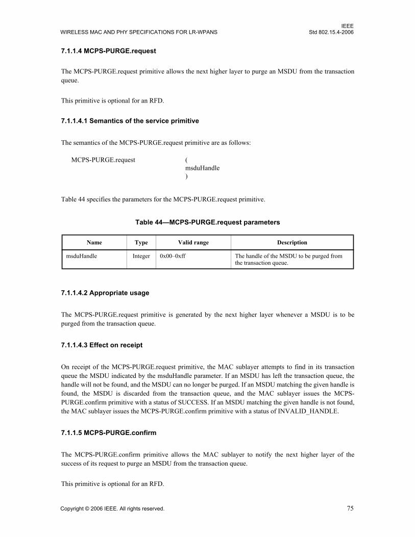
IEEEWIRELESS MAC AND PHY SPECIFICATIONS FOR LR-WPANS Std 802.15.4-2006
7.1.1.4 MCPS-PURGE.request
The MCPS-PURGE.request primitive allows the next higher layer to purge an MSDU from the transactionqueue.
This primitive is optional for an RFD.
7.1.1.4.1 Semantics of the service primitive
The semantics of the MCPS-PURGE.request primitive are as follows:
Table 44 specifies the parameters for the MCPS-PURGE.request primitive.
7.1.1.4.2 Appropriate usage
The MCPS-PURGE.request primitive is generated by the next higher layer whenever a MSDU is to bepurged from the transaction queue.
7.1.1.4.3 Effect on receipt
On receipt of the MCPS-PURGE.request primitive, the MAC sublayer attempts to find in its transactionqueue the MSDU indicated by the msduHandle parameter. If an MSDU has left the transaction queue, thehandle will not be found, and the MSDU can no longer be purged. If an MSDU matching the given handle isfound, the MSDU is discarded from the transaction queue, and the MAC sublayer issues the MCPS-PURGE.confirm primitive with a status of SUCCESS. If an MSDU matching the given handle is not found,the MAC sublayer issues the MCPS-PURGE.confirm primitive with a status of INVALID_HANDLE.
7.1.1.5 MCPS-PURGE.confirm
The MCPS-PURGE.confirm primitive allows the MAC sublayer to notify the next higher layer of thesuccess of its request to purge an MSDU from the transaction queue.
This primitive is optional for an RFD.
Table 44—MCPS-PURGE.request parameters
Name Type Valid range Description
msduHandle Integer 0x00–0xff The handle of the MSDU to be purged from the transaction queue.
MCPS-PURGE.request (msduHandle)
Copyright © 2006 IEEE. All rights reserved. 75

IEEEStd 802.15.4-2006 LOCAL AND METROPOLITAN AREA NETWORKS—PART 15.4:
7.1.1.5.1 Semantics of the service primitive
The semantics of the MCPS-PURGE.confirm primitive are as follows:
Table 45 specifies the parameters for the MCPS-PURGE.confirm primitive.
7.1.1.5.2 When generated
The MCPS-PURGE.confirm primitive is generated by the MAC sublayer entity in response to an MCPS-PURGE.request primitive. The MCPS-PURGE.confirm primitive returns a status of either SUCCESS,indicating that the purge request was successful, or INVALID_HANDLE, indicating an error. The statusvalues are fully described in 7.1.1.4.3.
7.1.1.5.3 Appropriate usage
On receipt of the MCPS-PURGE.confirm primitive, the next higher layer is notified of the result of itsrequest to purge an MSDU from the transaction queue. If the purge request was successful, the statusparameter will be set to SUCCESS. Otherwise, the status parameter will indicate the error.
7.1.1.6 Data service message sequence chart
Figure 30 illustrates a sequence of messages necessary for a successful data transfer between two devices.Figure 84 and Figure 85 (see 7.7) also illustrate this, including the steps taken by the PHY.
7.1.2 MAC management service
The MLME-SAP allows the transport of management commands between the next higher layer and theMLME. Table 46 summarizes the primitives supported by the MLME through the MLME-SAP interface.Primitives marked with a diamond (♦) are optional for an RFD. Primitives marked with an asterisk (*) areoptional for both device types (i.e., RFD and FFD). The primitives are discussed in the subclausesreferenced in the table.
Table 45—MCPS-PURGE.confirm parameters
Name Type Valid range Description
msduHandle Integer 0x00–0xff The handle of the MSDU requested to be purge from the transaction queue.
status Enumeration SUCCESS orINVALID_HANDLE
The status of the request to be purged an MSDU from the transaction queue.
MCPS-PURGE.confirm (msduHandle,status)
76 Copyright © 2006 IEEE. All rights reserved.

IEEEWIRELESS MAC AND PHY SPECIFICATIONS FOR LR-WPANS Std 802.15.4-2006
7.1.3 Association primitives
MLME-SAP association primitives define how a device becomes associated with a PAN.
All devices shall provide an interface for the request and confirm association primitives. The indication andresponse association primitives are optional for an RFD.
Table 46—Summary of the primitives accessed through the MLME-SAP
Name Request Indication Response Confirm
MLME-ASSOCIATE 7.1.3.1 7.1.3.2♦ 7.1.3.3♦ 7.1.3.4
MLME-DISASSOCIATE 7.1.4.1 7.1.4.2 7.1.4.3
MLME-BEACON-NOTIFY 7.1.5.1
MLME-GET 7.1.6.1 7.1.6.2
MLME-GTS 7.1.7.1∗ 7.1.7.3∗ 7.1.7.2∗
MLME-ORPHAN 7.1.8.1♦ 7.1.8.2♦
MLME-RESET 7.1.9.1 7.1.9.2
MLME-RX-ENABLE 7.1.10.1∗ 7.1.10.2∗
MLME-SCAN 7.1.11.1 7.1.11.2
MLME-COMM-STATUS 7.1.12.1
MLME-SET 7.1.13.1 7.1.13.2
MLME-START 7.1.14.1♦ 7.1.14.2♦
MLME-SYNC 7.1.15.1*
MLME-SYNC-LOSS 7.1.15.2
MLME-POLL 7.1.16.1 7.1.16.2
Figure 30—Message sequence chart describing the MAC data service
Copyright © 2006 IEEE. All rights reserved. 77

IEEEStd 802.15.4-2006 LOCAL AND METROPOLITAN AREA NETWORKS—PART 15.4:
7.1.3.1 MLME-ASSOCIATE.request
The MLME-ASSOCIATE.request primitive allows a device to request an association with a coordinator.
7.1.3.1.1 Semantics of the service primitive
The semantics of the MLME-ASSOCIATE.request primitive are as follows:
Table 47 specifies the parameters for the MLME-ASSOCIATE.request primitive.
Table 47—MLME-ASSOCIATE.request parameters
Name Type Valid range Description
LogicalChannel Integer Selected from the available logical channels supported by the PHY (see 6.1.2).
The logical channel on which to attempt association.
ChannelPage Integer Selected from the available channel pages supported by the PHY (see 6.1.2).
The channel page on which to attemptassociation.
CoordAddrMode Integer 0x02–0x03 The coordinator addressing mode for this primitive and subsequent MPDU. This value can take one of the following values:
2=16-bit short address.3=64-bit extended address.
CoordPANId Integer 0x0000–0xffff The identifier of the PAN with which to associate.
CoordAddress Device address
As specified by the CoordAddrMode parameter.
The address of the coordinator with which to associate.
CapabilityInformation Bitmap See 7.3.1.2 Specifies the operational capabilities of the associating device.
SecurityLevel Integer 0x00–0x07 The security level to be used (see Table 95 in 7.6.2.2.1).
MLME-ASSOCIATE.request (LogicalChannel,ChannelPage,CoordAddrMode,CoordPANId,CoordAddress,CapabilityInformation,SecurityLevel,KeyIdMode,KeySource,KeyIndex)
78 Copyright © 2006 IEEE. All rights reserved.

IEEEWIRELESS MAC AND PHY SPECIFICATIONS FOR LR-WPANS Std 802.15.4-2006
7.1.3.1.2 Appropriate usage
The MLME-ASSOCIATE.request primitive is generated by the next higher layer of an unassociated deviceand issued to its MLME to request an association with a PAN through a coordinator. If the device wishes toassociate through a coordinator on a beacon-enabled PAN, the MLME may optionally track the beacon ofthat coordinator prior to issuing this primitive.
7.1.3.1.3 Effect on receipt
On receipt of the MLME-ASSOCIATE.request primitive, the MLME of an unassociated device first updatesthe appropriate PHY and MAC PIB attributes and then generates an association request command (see7.3.1), as dictated by the association procedure described in 7.5.3.1.
The SecurityLevel parameter specifies the level of security to be applied to the association request commandframe. Typically, the association request command should not be implemented using security. However, ifthe device requesting association shares a key with the coordinator, then security may be specified.
If the SecurityLevel parameter is set to a valid value other than 0x00, indicating that security is required forthis frame, the MLME will set the Security Enabled subfield of the Frame Control field to one. The MACsublayer will perform outgoing processing on the frame based on the CoordAddress, SecurityLevel,KeyIdMode, KeySource, and KeyIndex parameters, as described in 7.5.8.2.1. If any error occurs duringoutgoing frame processing, the MLME will discard the frame and issue the MLME-ASSOCIATE.confirmprimitive with the error status returned by outgoing frame processing.
If the association request command cannot be sent to the coordinator due to the CSMA-CA algorithmindicating a busy channel, the MLME will issue the MLME-ASSOCIATE.confirm primitive with a status ofCHANNEL_ACCESS_FAILURE.
If the MLME successfully transmits an association request command, the MLME will expect anacknowledgment in return. If an acknowledgment is not received, the MLME will issue the MLME-ASSOCIATE.confirm primitive with a status of NO_ACK (see 7.5.6.4).
KeyIdMode Integer 0x00–0x03 The mode used to identify the key to be used (see Table 96 in 7.6.2.2.2). This parameter is ignored if the SecurityLevel parameter is set to 0x00.
KeySource Set of 0, 4, or 8 octets
As specified by the KeyIdMode parameter
The originator of the key to be used (see 7.6.2.4.1). This parameter is ignored if the KeyIdMode parameter is ignored or set to 0x00.
KeyIndex Integer 0x01–0xff The index of the key to be used (see 7.6.2.4.2). This parameter is ignored if the KeyIdMode parameter is ignored or set to 0x00.
Table 47—MLME-ASSOCIATE.request parameters (continued)
Name Type Valid range Description
Copyright © 2006 IEEE. All rights reserved. 79

IEEEStd 802.15.4-2006 LOCAL AND METROPOLITAN AREA NETWORKS—PART 15.4:
If the MLME of an unassociated device successfully receives an acknowledgment to its association requestcommand, the MLME will wait for a response to the request (see 7.5.3.1). If the MLME of the device doesnot receive a response, it will issue the MLME-ASSOCIATE.confirm primitive with a status of NO_DATA.
If the MLME of the device extracts an association response command frame from the coordinator, it willthen issue the MLME-ASSOCIATE.confirm primitive with a status equal to the contents of the AssociationStatus field in the association response command (see 7.3.2.3).
On receipt of the association request command, the MLME of the coordinator issues the MLME-ASSOCIATE.indication primitive.
If any parameter in the MLME-ASSOCIATE.request primitive is either not supported or out of range, theMLME will issue the MLME-ASSOCIATE.confirm primitive with a status of INVALID_PARAMETER.
7.1.3.2 MLME-ASSOCIATE.indication
The MLME-ASSOCIATE.indication primitive is used to indicate the reception of an association requestcommand.
7.1.3.2.1 Semantics of the service primitive
The semantics of the MLME-ASSOCIATE.indication primitive are as follows:
Table 48 specifies the parameters for the MLME-ASSOCIATE.indication primitive.
Table 48—MLME-ASSOCIATE.indication parameters
Name Type Valid range Description
DeviceAddress Device address
An extended 64-bit IEEE address.
The address of the device requesting association.
CapabilityInformation Bitmap See 7.3.1.2 The operational capabilities of the device requesting association.
SecurityLevel Integer 0x00–0x07 The security level purportedly used by the received MAC command frame (see Table 95 in 7.6.2.2.1).
KeyIdMode Integer 0x00–0x03 The mode used to identify the key purportedly used by the originator of the received frame (see Table 96 in 7.6.2.2.2). This parameter is invalid if the SecurityLevel parameter is set to 0x00.
MLME-ASSOCIATE.indication (DeviceAddress,CapabilityInformation,SecurityLevel,KeyIdMode,KeySource,KeyIndex)
80 Copyright © 2006 IEEE. All rights reserved.

IEEEWIRELESS MAC AND PHY SPECIFICATIONS FOR LR-WPANS Std 802.15.4-2006
7.1.3.2.2 When generated
The MLME-ASSOCIATE.indication primitive is generated by the MLME of the coordinator and issued toits next higher layer to indicate the reception of an association request command (see 7.3.1).
7.1.3.2.3 Appropriate usage
When the next higher layer of a coordinator receives the MLME-ASSOCIATE.indication primitive, thecoordinator determines whether to accept or reject the unassociated device using an algorithm outside thescope of this standard. The next higher layer of the coordinator then issues the MLME-ASSOCIATE.response primitive to its MLME.
The association decision and the response should become available at the coordinator within a time ofmacResponseWaitTime (see 7.5.3.1). After this time, the device requesting association attempts to extractthe association response command frame from the coordinator, using the method described in 7.5.6.3, inorder to determine whether the association was successful.
7.1.3.3 MLME-ASSOCIATE.response
The MLME-ASSOCIATE.response primitive is used to initiate a response to an MLME-ASSOCIATE.indication primitive.
7.1.3.3.1 Semantics of the service primitive
The semantics of the MLME-ASSOCIATE.response primitive are as follows:
Table 49 specifies the parameters for the MLME-ASSOCIATE.response primitive.
KeySource Set of 0, 4, or 8 octets
As specified by the KeyIdMode parameter
The originator of the key purportedly used by the originator of the received frame (see 7.6.2.4.1). This parameter is invalid if the KeyIdMode parameter is invalid or set to 0x00.
KeyIndex Integer 0x01–0xff The index of the key purportedly used by the originator of the received frame (see 7.6.2.4.2). This parameter is invalid if the KeyIdMode parameter is invalid or set to 0x00.
Table 48—MLME-ASSOCIATE.indication parameters (continued)
Name Type Valid range Description
MLME-ASSOCIATE.response (DeviceAddress,AssocShortAddress,status,SecurityLevel,KeyIdMode,KeySource,KeyIndex)
Copyright © 2006 IEEE. All rights reserved. 81

IEEEStd 802.15.4-2006 LOCAL AND METROPOLITAN AREA NETWORKS—PART 15.4:
7.1.3.3.2 Appropriate usage
The MLME-ASSOCIATE.response primitive is generated by the next higher layer of a coordinator andissued to its MLME in order to respond to the MLME-ASSOCIATE.indication primitive.
7.1.3.3.3 Effect on receipt
When the MLME of a coordinator receives the MLME-ASSOCIATE.response primitive, it generates anassociation response command (see 7.3.2). The command frame is sent to the device requesting associationusing indirect transmission, i.e., the command frame is added to the list of pending transactions stored on thecoordinator and extracted at the discretion of the device concerned using the method described in 7.5.6.3.
If the SecurityLevel parameter is set to a valid value other than 0x00, indicating that security is required forthis frame, the MLME will set the Security Enabled subfield of the Frame Control field to one. The MACsublayer will perform outgoing processing on the frame based the DeviceAddress, SecurityLevel,KeyIdMode, KeySource, and KeyIndex parameters, as described in 7.5.8.2.1. If any error occurs duringoutgoing frame processing, the MLME will discard the frame and issue the MLME-COMM-STATUS.indication primitive with the error status returned by outgoing frame processing.
Upon receipt of the MLME-ASSOCIATE.response primitive, the coordinator attempts to add theinformation contained in the primitive to its list of pending transactions. If there is no capacity to store thetransaction, the MAC sublayer will discard the frame and issue the MLME-COMM-STATUS.indicationprimitive with a status of TRANSACTION_OVERFLOW. If there is capacity to store the transaction, thecoordinator will add the information to the list. If the transaction is not handled withinmacTransactionPersistenceTime, the transaction information will be discarded and the MAC sublayer will
Table 49—MLME-ASSOCIATE.response parameters
Name Type Valid range Description
DeviceAddress Device address
An extended 64 bit IEEE address
The address of the device requesting association.
AssocShortAddress Integer 0x0000–0xffff The 16-bit short device address allocated by the coordinator on successful association. This parameter is set to 0xffff if the association was unsuccessful.
status Enumeration See 7.3.2.3 The status of the association attempt.
SecurityLevel Integer 0x00–0x07 The security level to be used (see Table 95 in 7.6.2.2.1).
KeyIdMode Integer 0x00–0x03 The mode used to identify the key to be used (see Table 96 in 7.6.2.2.2). This parameter is ignored if the SecurityLevel parameter is set to 0x00.
KeySource Set of 0, 4, or 8 octets
As specified by the KeyIdMode parameter
The originator of the key to be used (see 7.6.2.4.1). This parameter is ignored if the KeyIdMode parameter is ignored or set to 0x00.
KeyIndex Integer 0x01–0xff The index of the key to be used (see 7.6.2.4.2). This parameter is ignored if the KeyIdMode parameter is ignored or set to 0x00.
82 Copyright © 2006 IEEE. All rights reserved.

IEEEWIRELESS MAC AND PHY SPECIFICATIONS FOR LR-WPANS Std 802.15.4-2006
issue the MLME-COMM-STATUS.indication primitive with a status of TRANSACTION_EXPIRED. Thetransaction handling procedure is described in 7.5.5.
If the frame was successfully transmitted and an acknowledgment was received, if requested, the MACsublayer will issue the MLME-COMM-STATUS.indication primitive with a status of SUCCESS.
If any parameter in the MLME-ASSOCIATE.response primitive is not supported or is out of range, theMAC sublayer will issue the MLME-COMM-STATUS.indication primitive with a status ofINVALID_PARAMETER.
7.1.3.4 MLME-ASSOCIATE.confirm
The MLME-ASSOCIATE.confirm primitive is used to inform the next higher layer of the initiating devicewhether its request to associate was successful or unsuccessful.
7.1.3.4.1 Semantics of the service primitive
The semantics of the MLME-ASSOCIATE.confirm primitive are as follows:
Table 50 specifies the parameters for the MLME-ASSOCIATE.confirm primitive.
Table 50—MLME-ASSOCIATE.confirm parameters
Name Type Valid range Description
AssocShortAddress Integer 0x0000–0xffff The short device address allocated by the coordinator on successful association. This parameter will be equal to 0xffff if the association attempt was unsuccessful.
status Enumeration The value of the Status field of the association response command (see 7.3.2.3),SUCCESS,CHANNEL_ACCESS_FAILURE,NO_ACK,NO_DATA,COUNTER_ERROR, FRAME_TOO_LONG, IMPROPER_KEY_TYPE, IMPROPER_SECURITY_LEVEL, SECURITY_ERROR, UNAVAILABLE_KEY, UNSUPPORTED_LEGACY, UNSUPPORTED_SECURITYINVALID_PARAMETER
The status of the association attempt.
MLME-ASSOCIATE.confirm (AssocShortAddress,status,SecurityLevel,KeyIdMode,KeySource,KeyIndex)
Copyright © 2006 IEEE. All rights reserved. 83

IEEEStd 802.15.4-2006 LOCAL AND METROPOLITAN AREA NETWORKS—PART 15.4:
SecurityLevel Integer 0x00–0x07 If the primitive was generated following failed outgoing processing of an association request command:
The security level to be used (see Table 95 in 7.6.2.2.1).
If the primitive was generated following receipt of an association response command:
The security level purportedly used by the received frame (see Table 95 in 7.6.2.2.1).
KeyIdMode Integer 0x00–0x03 If the primitive was generated following failed outgoing processing of an association request command:
The mode used to identify the key to be used (see Table 96 in 7.6.2.2.2). This parameter is ignored if the SecurityLevel parameter is set to 0x00.
If the primitive was generated following receipt of an association response command:
The mode used to identify the key purportedly used by the originator of the received frame (see Table 96 in 7.6.2.2.2). This parameter is invalid if the SecurityLevel parameter is set to 0x00.
KeySource Set of 0, 4, or 8 octets
As specified by the KeyIdMode parameter
If the primitive was generated following failed outgoing processing of an association request command:
The originator of the key to be used (see 7.6.2.4.1). This parameter is ignored if the KeyIdMode parameter is ignored or set to 0x00.
If the primitive was generated following receipt of an association response command:
The originator of the key purportedly used by the originator of the received frame (see 7.6.2.4.1). This parameter is invalid if the KeyIdMode parameter is invalid or set to 0x00.
Table 50—MLME-ASSOCIATE.confirm parameters (continued)
Name Type Valid range Description
84 Copyright © 2006 IEEE. All rights reserved.

IEEEWIRELESS MAC AND PHY SPECIFICATIONS FOR LR-WPANS Std 802.15.4-2006
7.1.3.4.2 When generated
The MLME-ASSOCIATE.confirm primitive is generated by the initiating MLME and issued to its nexthigher layer in response to an MLME-ASSOCIATE.request primitive. If the request was successful, thestatus parameter will indicate a successful association, as contained in the Status field of the associationresponse command. Otherwise, the status parameter indicates either an error code from the receivedassociation response command or the appropriate error code from Table 50. The status values are fullydescribed in 7.1.3.1.3 and subclauses referenced by 7.1.3.1.3.
7.1.3.4.3 Appropriate usage
On receipt of the MLME-ASSOCIATE.confirm primitive, the next higher layer of the initiating device isnotified of the result of its request to associate with a coordinator. If the association attempt was successful,the status parameter will indicate a successful association, as contained in the Status field of the associationresponse command, and the device will be provided with a 16-bit short address (see Table 87 in 7.5.3.1). Ifthe association attempt was unsuccessful, the address will be equal to 0xffff, and the status parameter willindicate the error.
7.1.3.5 Association message sequence charts
Figure 31 illustrates a sequence of messages that may be used by a device that is not tracking the beacon ofthe coordinator (see 7.5.6.3) to successfully associate with a PAN. Figure 80 and Figure 81 (see 7.7)illustrate this same scenario, including steps taken by the PHY, for a device associating with a coordinatorand for a coordinator allowing association by a device, respectively.
KeyIndex Integer 0x01–0xff If the primitive was generated following failed outgoing processing of an association request command:
The index of the key to be used (see 7.6.2.4.2). This parameter is ignored if the KeyIdMode parameter is ignored or set to 0x00.
If the primitive was generated following receipt of an association response command:
The index of the key purportedly used by the originator of the received frame (see 7.6.2.4.2). This parameter is invalid if the KeyIdMode parameter is invalid or set to 0x00.
Table 50—MLME-ASSOCIATE.confirm parameters (continued)
Name Type Valid range Description
Copyright © 2006 IEEE. All rights reserved. 85
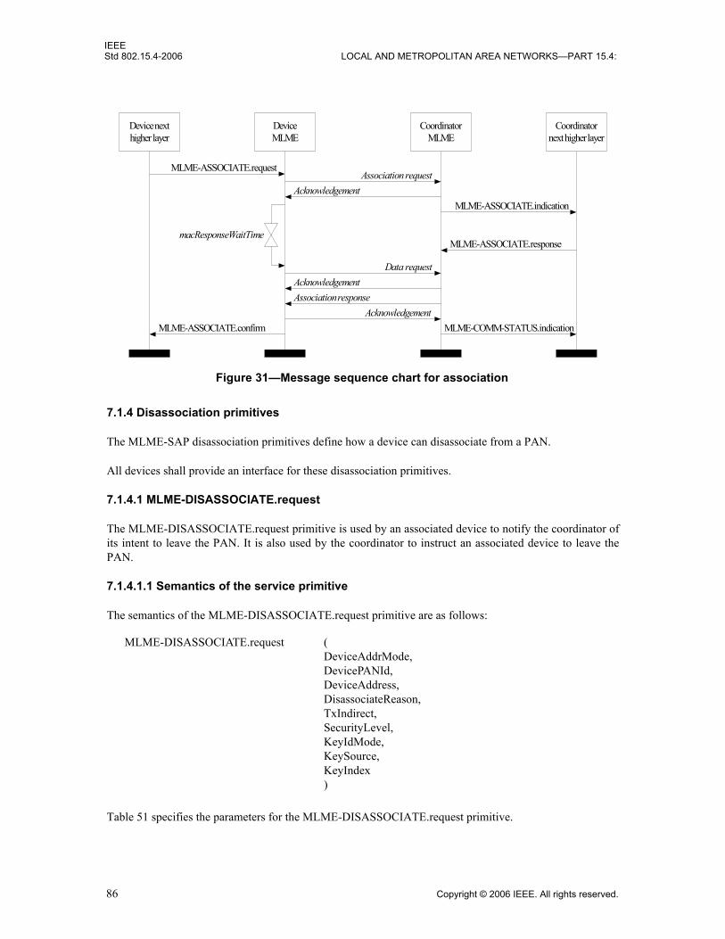
IEEEStd 802.15.4-2006 LOCAL AND METROPOLITAN AREA NETWORKS—PART 15.4:
7.1.4 Disassociation primitives
The MLME-SAP disassociation primitives define how a device can disassociate from a PAN.
All devices shall provide an interface for these disassociation primitives.
7.1.4.1 MLME-DISASSOCIATE.request
The MLME-DISASSOCIATE.request primitive is used by an associated device to notify the coordinator ofits intent to leave the PAN. It is also used by the coordinator to instruct an associated device to leave thePAN.
7.1.4.1.1 Semantics of the service primitive
The semantics of the MLME-DISASSOCIATE.request primitive are as follows:
Table 51 specifies the parameters for the MLME-DISASSOCIATE.request primitive.
Figure 31—Message sequence chart for association
Device nexthigher layer
DeviceMLME
MLME-ASSOCIATE.request
Data request
MLME-ASSOCIATE.indication
MLME-ASSOCIATE.confirm
Coordinatornext higher layer
CoordinatorMLME
Association request
AcknowledgementAssociation response
Acknowledgement
Acknowledgement
MLME-ASSOCIATE.response
MLME-COMM-STATUS.indication
macResponseWaitTime
MLME-DISASSOCIATE.request (DeviceAddrMode,DevicePANId,DeviceAddress,DisassociateReason,TxIndirect,SecurityLevel,KeyIdMode,KeySource,KeyIndex)
86 Copyright © 2006 IEEE. All rights reserved.

IEEEWIRELESS MAC AND PHY SPECIFICATIONS FOR LR-WPANS Std 802.15.4-2006
7.1.4.1.2 Appropriate usage
The MLME-DISASSOCIATE.request primitive is generated by the next higher layer of an associateddevice and issued to its MLME to request disassociation from the PAN. It is also generated by the nexthigher layer of the coordinator and issued to its MLME to instruct an associated device to leave the PAN.
7.1.4.1.3 Effect on receipt
On receipt of the MLME-DISASSOCIATE.request primitive, the MLME compares the DevicePANIdparameter with macPANId. If the DevicePANId parameter is not equal to macPANId, the MLME issues theMLME-DISASSOCIATE.confirm primitive with a status of INVALID_PARAMETER. If theDevicePANId parameter is equal to macPANId, the MLME evaluates the primitive address fields.
If the DeviceAddrMode parameter is equal to 0x02 and the DeviceAddress parameter is equal tomacCoordShortAddress or if the DeviceAddrMode parameter is equal to 0x03 and the DeviceAddressparameter is equal to macCoordExtendedAddress, the TxIndirect parameter is ignored, and the MLMEsends a disassociation notification command (see 7.3.3) to its coordinator in the CAP for a beacon-enabledPAN or immediately for a nonbeacon-enabled PAN.
Table 51—MLME-DISASSOCIATE.request parameters
Name Type Valid range Description
DeviceAddrMode Integer 0x02–0x03 The addressing mode of the device to which to send the disassociation notification command.
DevicePANId Integer 0x0000–0xffff The PAN identifier of the device to which to send the disassociation notification command.
DeviceAddress Device address
As specified by the DeviceAddrMode parameter.
The address of the device to which to send the disassociation notification command.
DisassociateReason Integer 0x00–0xff The reason for the disassociation (see 7.3.3.2).
TxIndirect Boolean TRUE or FALSE TRUE if the disassociation notification com-mand is to be sent indirectly.
SecurityLevel Integer 0x00–0x07 The security level to be used (see Table 95 in 7.6.2.2.1).
KeyIdMode Integer 0x00–0x03 The mode used to identify the key to be used (see Table 96 in 7.6.2.2.2). This parameter is ignored if the SecurityLevel parameter is set to 0x00.
KeySource Set of 0, 4, or 8 octets
As specified by the KeyIdMode parameter
The originator of the key to be used (see 7.6.2.4.1). This parameter is ignored if the KeyIdMode parameter is ignored or set to 0x00.
KeyIndex Integer 0x01–0xff The index of the key to be used (see 7.6.2.4.2). This parameter is ignored if the KeyIdMode parameter is ignored or set to 0x00.
Copyright © 2006 IEEE. All rights reserved. 87
IEEEStd 802.15.4-2006 LOCAL AND METROPOLITAN AREA NETWORKS—PART 15.4:
If the DeviceAddrMode parameter is equal to 0x02 and the DeviceAddress parameter is not equal tomacCoordShortAddress or if the DeviceAddrMode parameter is equal to 0x03 and the DeviceAddressparameter is not equal to macCoordExtendedAddress, and if this primitive was received by the MLME of acoordinator with the TxIndirect parameter set to TRUE, the disassociation notification command will besent using indirect transmission, i.e., the command frame is added to the list of pending transactions storedon the coordinator and extracted at the discretion of the device concerned using the method described in7.5.6.3.
If the DeviceAddrMode parameter is equal to 0x02 and the DeviceAddress parameter is not equal tomacCoordShortAddress or if the DeviceAddrMode parameter is equal to 0x03 and the DeviceAddressparameter is not equal to macCoordExtendedAddress, and if this primitive was received by the MLME of acoordinator with the TxIndirect parameter set to FALSE, the MLME sends a disassociation notificationcommand to the device in the CAP for a beacon-enabled PAN or immediately for a nonbeacon-enabledPAN.
Otherwise, the MLME issues the MLME-DISASSOCIATE.confirm primitive with a status ofINVALID_PARAMETER and does not generate a disassociation notification command.
If the disassociation notification command is to be sent using indirect transmission and there is no capacityto store the transaction, the MLME will discard the frame and issue the MLME-DISASSOCIATE.confirmprimitive with a status of TRANSACTION_OVERFLOW. If there is capacity to store the transaction, thecoordinator will add the information to the list. If the transaction is not handled within macTransaction-PersistenceTime, the transaction information will be discarded, and the MLME will issue theMLME-DISASSOCIATE.confirm with a status of TRANSACTION_EXPIRED. The transaction handlingprocedure is described in 7.5.5.
If the disassociation notification command cannot be sent due to a CSMA-CA algorithm failure and thisprimitive was received either by the MLME of a coordinator with the TxIndirect parameter set to FALSE orby the MLME of a device, the MLME will issue the MLME-DISASSOCIATE.confirm primitive with astatus of CHANNEL_ACCESS_FAILURE.
If the SecurityLevel parameter is set to a valid value other than 0x00, indicating that security is required forthis frame, the MLME will set the Security Enabled subfield of the Frame Control field to one. The MACsublayer will perform outgoing processing on the frame based on the DeviceAddress, SecurityLevel,KeyIdMode, KeySource, and KeyIndex parameters, as described in 7.5.8.2.1. If any error occurs duringoutgoing frame processing, the MLME will discard the frame and issue the MLME-DISASSOCIATE.confirm primitive with the error status returned by outgoing frame processing.
If the MLME successfully transmits a disassociation notification command, the MLME will expect anacknowledgment in return. If an acknowledgment is not received and this primitive was received either bythe MLME of a coordinator with the TxIndirect parameter set to FALSE or by the MLME of a device, theMLME will issue the MLME-DISASSOCIATE.confirm primitive with a status of NO_ACK (see 7.5.6.4).
If the MLME successfully transmits a disassociation notification command and receives anacknowledgment in return, the MLME will issue the MLME-DISASSOCIATE.confirm primitive with astatus of SUCCESS.
On receipt of the disassociation notification command, the MLME of the recipient issues the MLME-DISASSOCIATE.indication primitive.
If any parameter in the MLME-DISASSOCIATE.request primitive is not supported or is out of range, theMLME will issue the MLME-DISASSOCIATE.confirm primitive with a status ofINVALID_PARAMETER.
88 Copyright © 2006 IEEE. All rights reserved.
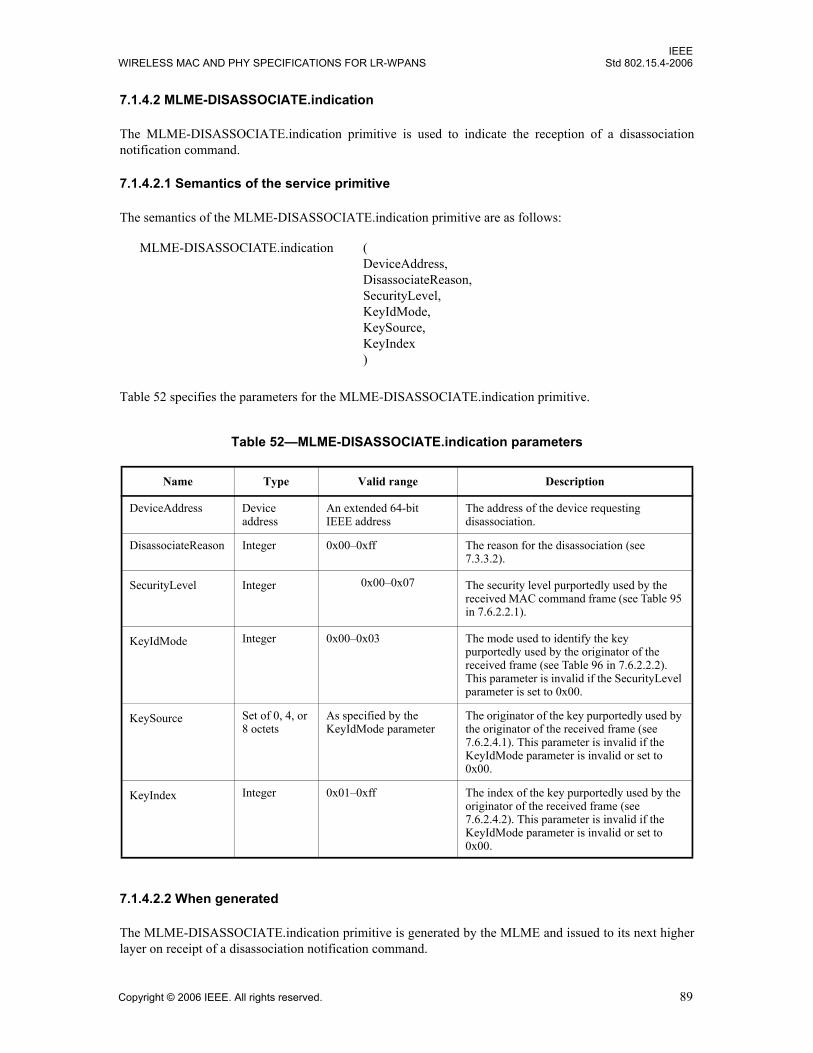
IEEEWIRELESS MAC AND PHY SPECIFICATIONS FOR LR-WPANS Std 802.15.4-2006
7.1.4.2 MLME-DISASSOCIATE.indication
The MLME-DISASSOCIATE.indication primitive is used to indicate the reception of a disassociationnotification command.
7.1.4.2.1 Semantics of the service primitive
The semantics of the MLME-DISASSOCIATE.indication primitive are as follows:
Table 52 specifies the parameters for the MLME-DISASSOCIATE.indication primitive.
7.1.4.2.2 When generated
The MLME-DISASSOCIATE.indication primitive is generated by the MLME and issued to its next higherlayer on receipt of a disassociation notification command.
Table 52—MLME-DISASSOCIATE.indication parameters
Name Type Valid range Description
DeviceAddress Device address
An extended 64-bit IEEE address
The address of the device requesting disassociation.
DisassociateReason Integer 0x00–0xff The reason for the disassociation (see 7.3.3.2).
SecurityLevel Integer 0x00–0x07 The security level purportedly used by the received MAC command frame (see Table 95 in 7.6.2.2.1).
KeyIdMode Integer 0x00–0x03 The mode used to identify the key purportedly used by the originator of the received frame (see Table 96 in 7.6.2.2.2). This parameter is invalid if the SecurityLevel parameter is set to 0x00.
KeySource Set of 0, 4, or 8 octets
As specified by the KeyIdMode parameter
The originator of the key purportedly used by the originator of the received frame (see 7.6.2.4.1). This parameter is invalid if the KeyIdMode parameter is invalid or set to 0x00.
KeyIndex Integer 0x01–0xff The index of the key purportedly used by the originator of the received frame (see 7.6.2.4.2). This parameter is invalid if the KeyIdMode parameter is invalid or set to 0x00.
MLME-DISASSOCIATE.indication (DeviceAddress,DisassociateReason,SecurityLevel,KeyIdMode,KeySource,KeyIndex)
Copyright © 2006 IEEE. All rights reserved. 89
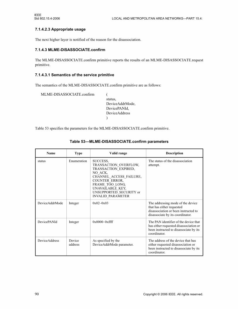
IEEEStd 802.15.4-2006 LOCAL AND METROPOLITAN AREA NETWORKS—PART 15.4:
7.1.4.2.3 Appropriate usage
The next higher layer is notified of the reason for the disassociation.
7.1.4.3 MLME-DISASSOCIATE.confirm
The MLME-DISASSOCIATE.confirm primitive reports the results of an MLME-DISASSOCIATE.requestprimitive.
7.1.4.3.1 Semantics of the service primitive
The semantics of the MLME-DISASSOCIATE.confirm primitive are as follows:
Table 53 specifies the parameters for the MLME-DISASSOCIATE.confirm primitive.
Table 53—MLME-DISASSOCIATE.confirm parameters
Name Type Valid range Description
status Enumeration SUCCESS,TRANSACTION_OVERFLOW,TRANSACTION_EXPIRED,NO_ACK,CHANNEL_ACCESS_FAILURE,COUNTER_ERROR, FRAME_TOO_LONG, UNAVAILABLE_KEY, UNSUPPORTED_SECURITY orINVALID_PARAMETER
The status of the disassociation attempt.
DeviceAddrMode Integer 0x02–0x03 The addressing mode of the device that has either requested disassociation or been instructed to disassociate by its coordinator.
DevicePANId Integer 0x0000–0xffff The PAN identifier of the device that has either requested disassociation or been instructed to disassociate by its coordinator.
DeviceAddress Device address
As specified by the DeviceAddrMode parameter.
The address of the device that has either requested disassociation or been instructed to disassociate by its coordinator.
MLME-DISASSOCIATE.confirm (status,DeviceAddrMode,DevicePANId,DeviceAddress)
90 Copyright © 2006 IEEE. All rights reserved.

IEEEWIRELESS MAC AND PHY SPECIFICATIONS FOR LR-WPANS Std 802.15.4-2006
7.1.4.3.2 When generated
The MLME-DISASSOCIATE.confirm primitive is generated by the initiating MLME and issued to its nexthigher layer in response to an MLME-DISASSOCIATE.request primitive. This primitive returns a status ofeither SUCCESS, indicating that the disassociation request was successful, or the appropriate error code.The status values are fully described in 7.1.4.1.3 and subclauses referenced by 7.1.4.1.3.
7.1.4.3.3 Appropriate usage
On receipt of the MLME-DISASSOCIATE.confirm primitive, the next higher layer of the initiating deviceis notified of the result of the disassociation attempt. If the disassociation attempt was successful, the statusparameter will be set to SUCCESS. Otherwise, the status parameter indicates the error.
7.1.4.4 Disassociation message sequence charts
The request to disassociate may originate either from a device or from the coordinator through which thedevice has associated. Figure 32 illustrates the sequence of messages necessary for a device to successfullydisassociate itself from the PAN.
Figure 33 illustrates the sequence necessary for a coordinator in a beacon-enabled PAN to successfullydisassociate a device from its PAN using indirect transmission.
Figure 32—Message sequence chart for disassociation initiated by a device
Devicenext higher layer
DeviceMLME
MLME-DISASSOCIATE.request
MLME-DISASSOCIATE.indicationMLME-DISASSOCIATE.confirm(SUCCESS)
Coordinatornext higher layer
CoordinatorMLME
Disassociation notification
Acknowledgement
Copyright © 2006 IEEE. All rights reserved. 91

IEEEStd 802.15.4-2006 LOCAL AND METROPOLITAN AREA NETWORKS—PART 15.4:
7.1.5 Beacon notification primitive
The MLME-SAP beacon notification primitive defines how a device may be notified when a beacon isreceived during normal operating conditions.
All devices shall provide an interface for the beacon notification primitive.
7.1.5.1 MLME-BEACON-NOTIFY.indication
The MLME-BEACON-NOTIFY.indication primitive is used to send parameters contained within a beaconframe received by the MAC sublayer to the next higher layer. The primitive also sends a measure of the LQIand the time the beacon frame was received.
7.1.5.1.1 Semantics of the service primitive
The semantics of the MLME-BEACON-NOTIFY.indication primitive are as follows:
Table 54 specifies the parameters for the MLME-BEACON-NOTIFY.indication primitive.
Figure 33—Message sequence chart for disassociation initiated by a coordinator, using indirect transmission, in a beacon-enabled PAN
CoordinatorMLME Device MLME
Disassociation notification
Acknowledgement
Coordinatornext higher
layer
Device nexthigher layer
MLME-DISASSOCIATE.indication
Beacon (with data pending)
Data request
Acknowledgement
MLME-DISASSOCIATE.request(TxIndirect = TRUE)
MLME-DISASSOCIATE.confirm(SUCCESS)
MLME-BEACON-NOTIFY.indication (BSN,PANDescriptor,PendAddrSpec,AddrList,sduLength,sdu)
92 Copyright © 2006 IEEE. All rights reserved.

IEEEWIRELESS MAC AND PHY SPECIFICATIONS FOR LR-WPANS Std 802.15.4-2006
Table 55 describes the elements of the PANDescriptor type.
Table 54—MLME-BEACON-NOTIFY.indication parameters
Name Type Valid range Description
BSN Integer 0x00–0xff The beacon sequence number.
PANDescriptor PANDescriptor value
See Table 55 The PANDescriptor for the received beacon.
PendAddrSpec Bitmap See 7.2.2.1.6 The beacon pending address specification.
AddrList List of device addresses
— The list of addresses of the devices for which the beacon source has data.
sduLength Integer 0 – aMaxBeaconPayloadLength The number of octets contained in the beacon payload of the beacon frame received by the MAC sublayer.
sdu Set of octets — The set of octets comprising the beacon payload to be transferred from the MAC sublayer entity to the next higher layer.
Table 55—Elements of PANDescriptor
Name Type Valid range Description
CoordAddrMode Integer 0x02–0x03 The coordinator addressing mode corresponding to the received beacon frame. This value can take one of the following values:2 = 16-bit short address.3 = 64-bit extended address.
CoordPANId Integer 0x0000–0xffff The PAN identifier of the coordinator as specified in the received beacon frame.
CoordAddress Device address
As specified by the CoordAddrMode parameter
The address of the coordinator as specified in the received beacon frame.
LogicalChannel Integer Selected from the available logical channels supported by the PHY (see 6.1.2)
The current logical channel occupied by the network.
ChannelPage Integer Selected from the available channel pages supported by the PHY (see 6.1.2)
The current channel page occupied by thenetwork.
SuperframeSpec Bitmap See 7.2.2.1.2 The superframe specification as specified in the received beacon frame.
GTSPermit Boolean TRUE or FALSE TRUE if the beacon is from the PAN coordinator that is accepting GTS requests.
LinkQuality Integer 0x00–0xff The LQI at which the network beacon was received. Lower values represent lower LQI (see 6.9.8).
Copyright © 2006 IEEE. All rights reserved. 93
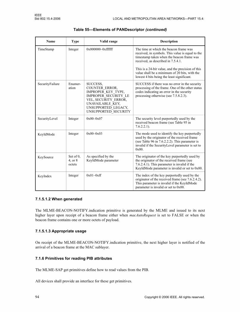
IEEEStd 802.15.4-2006 LOCAL AND METROPOLITAN AREA NETWORKS—PART 15.4:
7.1.5.1.2 When generated
The MLME-BEACON-NOTIFY.indication primitive is generated by the MLME and issued to its nexthigher layer upon receipt of a beacon frame either when macAutoRequest is set to FALSE or when thebeacon frame contains one or more octets of payload.
7.1.5.1.3 Appropriate usage
On receipt of the MLME-BEACON-NOTIFY.indication primitive, the next higher layer is notified of thearrival of a beacon frame at the MAC sublayer.
7.1.6 Primitives for reading PIB attributes
The MLME-SAP get primitives define how to read values from the PIB.
All devices shall provide an interface for these get primitives.
TimeStamp Integer 0x000000–0xffffff The time at which the beacon frame was received, in symbols. This value is equal to the timestamp taken when the beacon frame was received, as described in 7.5.4.1.
This is a 24-bit value, and the precision of this value shall be a minimum of 20 bits, with the lowest 4 bits being the least significant.
SecurityFailure Enumer-ation
SUCCESS,COUNTER_ERROR, IMPROPER_KEY_TYPE, IMPROPER_SECURITY_LEVEL, SECURITY_ERROR, UNAVAILABLE_KEY, UNSUPPORTED_LEGACY, UNSUPPORTED_SECURITY
SUCCESS if there was no error in the security processing of the frame. One of the other status codes indicating an error in the security processing otherwise (see 7.5.8.2.3).
SecurityLevel Integer 0x00–0x07 The security level purportedly used by the received beacon frame (see Table 95 in 7.6.2.2.1).
KeyIdMode Integer 0x00–0x03 The mode used to identify the key purportedly used by the originator of the received frame (see Table 96 in 7.6.2.2.2). This parameter is invalid if the SecurityLevel parameter is set to 0x00.
KeySource Set of 0, 4, or 8 octets
As specified by the KeyIdMode parameter
The originator of the key purportedly used by the originator of the received frame (see 7.6.2.4.1). This parameter is invalid if the KeyIdMode parameter is invalid or set to 0x00.
KeyIndex Integer 0x01–0xff The index of the key purportedly used by the originator of the received frame (see 7.6.2.4.2). This parameter is invalid if the KeyIdMode parameter is invalid or set to 0x00.
Table 55—Elements of PANDescriptor (continued)
Name Type Valid range Description
94 Copyright © 2006 IEEE. All rights reserved.

IEEEWIRELESS MAC AND PHY SPECIFICATIONS FOR LR-WPANS Std 802.15.4-2006
7.1.6.1 MLME-GET.request
The MLME-GET.request primitive requests information about a given PIB attribute.
7.1.6.1.1 Semantics of the service primitive
The semantics of the MLME-GET.request primitive are as follows:
Table 56 specifies the parameters for the MLME-GET.request primitive.
7.1.6.1.2 Appropriate usage
The MLME-GET.request primitive is generated by the next higher layer and issued to its MLME to obtaininformation from the PIB.
7.1.6.1.3 Effect on receipt
On receipt of the MLME-GET.request primitive, the MLME checks to see if the PIB attribute is a MAC PIBattribute or PHY PIB attribute. If the requested attribute is a MAC attribute, the MLME attempts to retrievethe requested MAC PIB attribute from its database. If the identifier of the PIB attribute is not found in thedatabase, the MLME will issue the MLME-GET.confirm primitive with a status ofUNSUPPORTED_ATTRIBUTE. If the PIBAttributeIndex parameter specifies an index for a table that isout of range, the MLME will issue the MLME-GET.confirm primitive with a status of INVALID_INDEX.If the requested MAC PIB attribute is successfully retrieved, the MLME will issue the MLME-GET.confirmprimitive with a status of SUCCESS.
If the requested attribute is a PHY PIB attribute, the request is passed to the PHY by issuing the PLME-GET.request primitive. Once the MLME receives the PLME-GET.confirm primitive, it will translate thereceived status value because the status values used by the PHY are not the same as those used by theMLME (e.g., the status values for SUCCESS are 0x00 and 0x07 in the MAC and PHY enumeration tables,respectively). Following the translation, the MLME will issue the MLME-GET.confirm primitive to thenext higher layer with the status parameter resulting from the translation and the PIBAttribute andPIBAttributeValue parameters equal to those returned by the PLME primitive.
Table 56—MLME-GET.request parameters
Name Type Valid range Description
PIBAttribute Integer See Table 86 and Table 88
The identifier of the PIB attribute to read.
PIBAttributeIndex Integer Attribute specific;see Table 88
The index within the table of the specified PIB attribute to read. This parameter is valid only for MAC PIB attributes that are tables; it is ignored when accessing PHY PIB attributes.
MLME-GET.request (PIBAttribute,PIBAttributeIndex)
Copyright © 2006 IEEE. All rights reserved. 95

IEEEStd 802.15.4-2006 LOCAL AND METROPOLITAN AREA NETWORKS—PART 15.4:
7.1.6.2 MLME-GET.confirm
The MLME-GET.confirm primitive reports the results of an information request from the PIB.
7.1.6.2.1 Semantics of the service primitive
The semantics of the MLME-GET.confirm primitive are as follows:
Table 57 specifies the parameters for the MLME-GET.confirm primitive.
7.1.6.2.2 When generated
The MLME-GET.confirm primitive is generated by the MLME and issued to its next higher layer inresponse to an MLME-GET.request primitive. This primitive returns a status of either SUCCESS, indicatingthat the request to read a PIB attribute was successful, or an error code of UNSUPPORTED_ATTRIBUTE.When an error code of UNSUPPORTED_ATTRIBUTE is returned, the PIBAttribute value parameter willbe set to length zero. The status values are fully described in 7.1.6.1.3.
7.1.6.2.3 Appropriate usage
On receipt of the MLME-GET.confirm primitive, the next higher layer is notified of the results of its requestto read a PIB attribute. If the request to read a PIB attribute was successful, the status parameter will be set toSUCCESS. Otherwise, the status parameter indicates the error.
Table 57—MLME-GET.confirm parameters
Name Type Valid range Description
status Enumeration SUCCESS,UNSUPPORTED_ATTRIBUTE or INVALID_INDEX
The result of the request for PIB attribute information.
PIBAttribute Integer See Table 86 and Table 88 The identifier of the PIB attribute that was read.
PIBAttributeIndex Integer Attribute specific;see Table 88
The index within the table or array of the specified PIB attribute to read. This parameter is valid only for MAC PIB attributes that are tables or arrays; it is ignored when accessing PHY PIB attributes.
PIBAttributeValue Various Attribute specific;see Table 86 and Table 88
The value of the indicated PIB attribute that was read.
This parameter has zero length when the status parameter is set to UNSUPPORTED_ATTRIBUTE.
MLME-GET.confirm (status,PIBAttribute,PIBAttributeIndex,PIBAttributeValue)
96 Copyright © 2006 IEEE. All rights reserved.

IEEEWIRELESS MAC AND PHY SPECIFICATIONS FOR LR-WPANS Std 802.15.4-2006
7.1.7 GTS management primitives
The MLME-SAP GTS management primitives define how GTSs are requested and maintained. A devicewishing to use these primitives and GTSs in general will already be tracking the beacons of its PANcoordinator.
These GTS management primitives are optional.
7.1.7.1 MLME-GTS.request
The MLME-GTS.request primitive allows a device to send a request to the PAN coordinator to allocate anew GTS or to deallocate an existing GTS. This primitive is also used by the PAN coordinator to initiate aGTS deallocation.
7.1.7.1.1 Semantics of the service primitive
The semantics of the MLME-GTS.request primitive are as follows:
Table 58 specifies the parameters for the MLME-GTS.request primitive.
7.1.7.1.2 Appropriate usage
The MLME-GTS.request primitive is generated by the next higher layer of a device and issued to its MLMEto request the allocation of a new GTS or to request the deallocation of an existing GTS. It is also generatedby the next higher layer of the PAN coordinator and issued to its MLME to request the deallocation of anexisting GTS.
Table 58—MLME-GTS.request parameters
Name Type Valid range Description
GTSCharacteristics GTScharacteristics
See 7.3.9.2 The characteristics of the GTS request, including whether the request is for the allocation of a new GTS or the deallocation of an existing GTS.
SecurityLevel Integer 0x00–0x07 The security level to be used (see Table 95 in 7.6.2.2.1).
KeyIdMode Integer 0x00–0x03 The mode used to identify the key to be used (see Table 96 in 7.6.2.2.2). This parameter is ignored if the SecurityLevel parameter is set to 0x00.
KeySource Set of 0, 4, or 8 octets
As specified by the KeyIdMode parameter
The originator of the key to be used (see 7.6.2.4.1). This parameter is ignored if the KeyIdMode parameter is ignored or set to 0x00.
KeyIndex Integer 0x01–0xff The index of the key to be used (see 7.6.2.4.2). This parameter is ignored if the KeyIdMode parameter is ignored or set to 0x00.
MLME-GTS.request (GTSCharacteristics,SecurityLevel,KeyIdMode,KeySource,KeyIndex)
Copyright © 2006 IEEE. All rights reserved. 97

IEEEStd 802.15.4-2006 LOCAL AND METROPOLITAN AREA NETWORKS—PART 15.4:
7.1.7.1.3 Effect on receipt
On receipt of the MLME-GTS.request primitive by a device, the MLME of a device attempts to generate aGTS request command (see 7.3.9) with the information contained in this primitive and, if successful, sends itto the PAN coordinator.
If macShortAddress is equal to 0xfffe or 0xffff, the device is not permitted to request a GTS. In this case, theMLME issues the MLME-GTS.confirm primitive containing a status of NO_SHORT_ADDRESS.
If the SecurityLevel parameter is set to a valid value other than 0x00, indicating that security is required forthis frame, the MLME will set the Security Enabled subfield of the Frame Control field to one. The MACsublayer will perform outgoing processing on the frame based on macCoordExtendedAddress and theSecurityLevel, KeyIdMode, KeySource, and KeyIndex parameters, as described in 7.5.8.2.1. If any erroroccurs during outgoing frame processing, the MLME will discard the frame and issue the MLME-GTS.confirm primitive with the error status returned by outgoing frame processing.
If the GTS request command cannot be sent due to a CSMA-CA algorithm failure, the MLME will issue theMLME-GTS.confirm primitive with a status of CHANNEL_ACCESS_FAILURE.
If the MLME successfully transmits a GTS request command, the MLME will expect an acknowledgment inreturn. If an acknowledgment is not received, the MLME will issue the MLME-GTS.confirm primitive witha status of NO_ACK (see 7.5.6.4).
If a GTS is being allocated (see 7.5.7.2) and the request has been acknowledged, the device will wait for aconfirmation via a GTS descriptor specified in a beacon frame from its PAN coordinator. If the MLME ofthe PAN coordinator can allocate the requested GTS, it will issue the MLME-GTS.indication primitive withthe characteristics of the allocated GTS and generate a GTS descriptor with the characteristics of theallocated GTS and the 16-bit short address of the requesting device. If the MLME of the PAN coordinatorcannot allocate the requested GTS, it will generate a GTS descriptor with a start slot of zero and the shortaddress of the requesting device.
If the device receives a beacon frame from its PAN coordinator with a GTS descriptor containing a 16-bitshort address that matches macShortAddress, the device will process the descriptor. If no descriptor for thatdevice is received, the MLME will issue the MLME-GTS.confirm primitive with a status of NO_DATA.
If a descriptor is received that matches the characteristics requested (indicating that the PAN coordinator hasapproved the GTS allocation request), the MLME of the device will issue the MLME-GTS.confirmprimitive with a status of SUCCESS and a GTSCharacteristics parameter with a characteristics type equal toone, indicating a GTS allocation.
If the descriptor is received with a start slot of zero (indicating that the PAN coordinator has denied the GTSallocation request), the device requesting the GTS issues the MLME-GTS.confirm primitive with a status ofDENIED, indicating that the GTSCharacteristics parameter is to be ignored.
If a GTS is being deallocated (see 7.5.7.4) at the request of a device and the request has been acknowledgedby the PAN coordinator, the device will issue the MLME-GTS.confirm primitive with a status of SUCCESSand a GTSCharacteristics parameter with a characteristics type equal to zero, indicating a GTS deallocation.On receipt of a GTS request command with a request type indicating a GTS deallocation, the PANcoordinator will acknowledge the frame and deallocates the GTS. The MLME of the PAN coordinator willthen issue the MLME-GTS.indication primitive with the appropriate GTS characteristics. If the PANcoordinator does not receive the deallocation request, countermeasures can be applied by the PANcoordinator to ensure consistency is maintained (see 7.5.7.6).
98 Copyright © 2006 IEEE. All rights reserved.
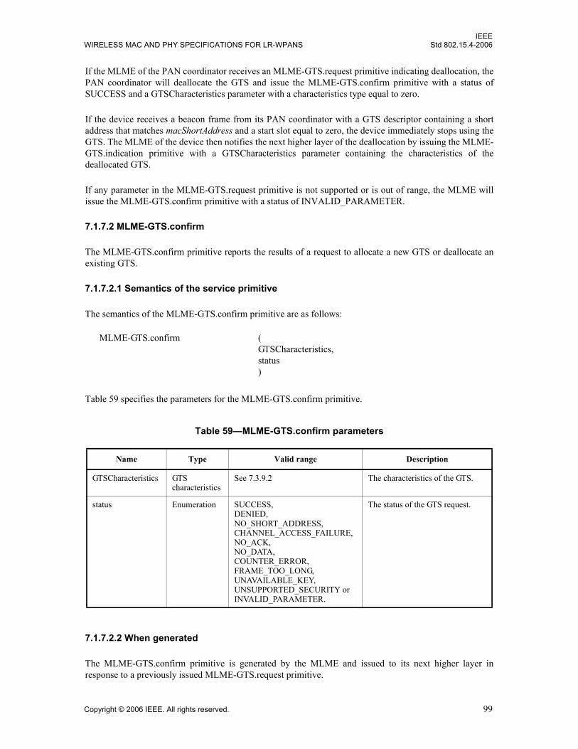
IEEEWIRELESS MAC AND PHY SPECIFICATIONS FOR LR-WPANS Std 802.15.4-2006
If the MLME of the PAN coordinator receives an MLME-GTS.request primitive indicating deallocation, thePAN coordinator will deallocate the GTS and issue the MLME-GTS.confirm primitive with a status ofSUCCESS and a GTSCharacteristics parameter with a characteristics type equal to zero.
If the device receives a beacon frame from its PAN coordinator with a GTS descriptor containing a shortaddress that matches macShortAddress and a start slot equal to zero, the device immediately stops using theGTS. The MLME of the device then notifies the next higher layer of the deallocation by issuing the MLME-GTS.indication primitive with a GTSCharacteristics parameter containing the characteristics of thedeallocated GTS.
If any parameter in the MLME-GTS.request primitive is not supported or is out of range, the MLME willissue the MLME-GTS.confirm primitive with a status of INVALID_PARAMETER.
7.1.7.2 MLME-GTS.confirm
The MLME-GTS.confirm primitive reports the results of a request to allocate a new GTS or deallocate anexisting GTS.
7.1.7.2.1 Semantics of the service primitive
The semantics of the MLME-GTS.confirm primitive are as follows:
Table 59 specifies the parameters for the MLME-GTS.confirm primitive.
7.1.7.2.2 When generated
The MLME-GTS.confirm primitive is generated by the MLME and issued to its next higher layer inresponse to a previously issued MLME-GTS.request primitive.
Table 59—MLME-GTS.confirm parameters
Name Type Valid range Description
GTSCharacteristics GTScharacteristics
See 7.3.9.2 The characteristics of the GTS.
status Enumeration SUCCESS,DENIED,NO_SHORT_ADDRESS,CHANNEL_ACCESS_FAILURE,NO_ACK,NO_DATA,COUNTER_ERROR, FRAME_TOO_LONG, UNAVAILABLE_KEY, UNSUPPORTED_SECURITY orINVALID_PARAMETER.
The status of the GTS request.
MLME-GTS.confirm (GTSCharacteristics,status)
Copyright © 2006 IEEE. All rights reserved. 99
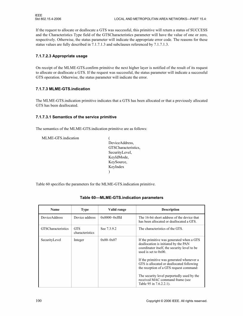
IEEEStd 802.15.4-2006 LOCAL AND METROPOLITAN AREA NETWORKS—PART 15.4:
If the request to allocate or deallocate a GTS was successful, this primitive will return a status of SUCCESSand the Characteristics Type field of the GTSCharacteristics parameter will have the value of one or zero,respectively. Otherwise, the status parameter will indicate the appropriate error code. The reasons for thesestatus values are fully described in 7.1.7.1.3 and subclauses referenced by 7.1.7.1.3.
7.1.7.2.3 Appropriate usage
On receipt of the MLME-GTS.confirm primitive the next higher layer is notified of the result of its requestto allocate or deallocate a GTS. If the request was successful, the status parameter will indicate a successfulGTS operation. Otherwise, the status parameter will indicate the error.
7.1.7.3 MLME-GTS.indication
The MLME-GTS.indication primitive indicates that a GTS has been allocated or that a previously allocatedGTS has been deallocated.
7.1.7.3.1 Semantics of the service primitive
The semantics of the MLME-GTS.indication primitive are as follows:
Table 60 specifies the parameters for the MLME-GTS.indication primitive.
Table 60—MLME-GTS.indication parameters
Name Type Valid range Description
DeviceAddress Device address 0x0000–0xfffd The 16-bit short address of the device that has been allocated or deallocated a GTS.
GTSCharacteristics GTScharacteristics
See 7.3.9.2 The characteristics of the GTS.
SecurityLevel Integer 0x00–0x07 If the primitive was generated when a GTS deallocation is initiated by the PAN coordinator itself, the security level to be used is set to 0x00.
If the primitive was generated whenever a GTS is allocated or deallocated following the reception of a GTS request command:
The security level purportedly used by the received MAC command frame (see Table 95 in 7.6.2.2.1).
MLME-GTS.indication (DeviceAddress,GTSCharacteristics,SecurityLevel,KeyIdMode,KeySource,KeyIndex)
100 Copyright © 2006 IEEE. All rights reserved.

IEEEWIRELESS MAC AND PHY SPECIFICATIONS FOR LR-WPANS Std 802.15.4-2006
7.1.7.3.2 When generated
The MLME-GTS.indication primitive is generated by the MLME of the PAN coordinator to its next higherlayer whenever a GTS is allocated or deallocated following the reception of a GTS request command (see7.3.9) by the MLME. The MLME of the PAN coordinator also generates this primitive when a GTSdeallocation is initiated by the PAN coordinator itself. The Characteristics Type field in theGTSCharacteristics parameter will be equal to one if a GTS has been allocated or zero if a GTS has beendeallocated.
This primitive is generated by the MLME of a device and issued to its next higher layer when the PANcoordinator has deallocated one of its GTSs. In this case, the Characteristics Type field of theGTSCharacteristics parameter is equal to zero.
KeyIdMode Integer 0x00–0x03 If the primitive was generated when a GTS deallocation is initiated by the PAN coordinator itself, this parameter is ignored.
If the primitive was generated whenever a GTS is allocated or deallocated following the reception of a GTS request command:
The mode used to identify the key purportedly used by the originator of the received frame (see Table 96 in 7.6.2.2.2). This parameter is invalid if the SecurityLevel parameter is set to 0x00.
KeySource Set of 0, 4, or 8 octets
As specified by the KeyIdMode parameter
If the primitive was generated when a GTS deallocation is initiated by the PAN coordinator itself, this parameter is ignored.
If the primitive was generated whenever a GTS is allocated or deallocated following the reception of a GTS request command:
The originator of the key purportedly used by the originator of the received frame (see 7.6.2.4.1). This parameter is invalid if the KeyIdMode parameter is invalid or set to 0x00.
KeyIndex Integer 0x01–0xff If the primitive was generated when a GTS deallocation is initiated by the PAN coordinator itself, this parameter is ignored.
If the primitive was generated whenever a GTS is allocated or deallocated following the reception of a GTS request command:
The index of the key purportedly used by the originator of the received frame (see 7.6.2.4.2). This parameter is invalid if the KeyIdMode parameter is invalid or set to 0x00.
Table 60—MLME-GTS.indication parameters (continued)
Name Type Valid range Description
Copyright © 2006 IEEE. All rights reserved. 101

IEEEStd 802.15.4-2006 LOCAL AND METROPOLITAN AREA NETWORKS—PART 15.4:
7.1.7.3.3 Appropriate usage
On receipt of the MLME-GTS.indication primitive the next higher layer is notified of the allocation or de-allocation of a GTS.
7.1.7.4 GTS management message sequence charts
Figure 34 and Figure 35 illustrate the sequence of messages necessary for successful GTS management. Thefirst depicts the message flow for the case in which the device initiates the GTS allocation. The seconddepicts the message flow for the two cases for which a GTS deallocation occurs, first, by a device (a) and,second, by the PAN coordinator (b).
Figure 34—Message sequence chart for GTS allocation initiated by a device
Figure 35—Message sequence chart for GTS deallocation initiated by a device (a) and the PAN coordinator (b)
Devicenext higher layer
DeviceMLME
MLME-GTS.request
MLME-GTS.indicationMLME-GTS.confirm
PAN Coordinatornext higher layer
PAN CoordinatorMLME
GTS request
Acknowledgement
MLME-GTS.confirm
MLME-GTS.request
MLME-GTS.indication
Beacon (with GTS descriptor)
a)
b)
102 Copyright © 2006 IEEE. All rights reserved.

IEEEWIRELESS MAC AND PHY SPECIFICATIONS FOR LR-WPANS Std 802.15.4-2006
7.1.8 Primitives for orphan notification
MLME-SAP orphan notification primitives define how a coordinator can issue a notification of an orphaneddevice.
These orphan notification primitives are optional for an RFD.
7.1.8.1 MLME-ORPHAN.indication
The MLME-ORPHAN.indication primitive allows the MLME of a coordinator to notify the next higherlayer of the presence of an orphaned device.
7.1.8.1.1 Semantics of the service primitive
The semantics of the MLME-ORPHAN.indication primitive are as follows:
Table 61 specifies the parameters for the MLME-ORPHAN.indication primitive.
7.1.8.1.2 When generated
The MLME-ORPHAN.indication primitive is generated by the MLME of a coordinator and issued to itsnext higher layer on receipt of an orphan notification command (see 7.3.6).
Table 61—MLME-ORPHAN.indication parameters
Name Type Valid range Description
OrphanAddress Device address
Extended 64-bit IEEE address
The address of the orphaned device.
SecurityLevel Integer 0x00–0x07 The security level purportedly used by the received MAC command frame (see Table 95 in 7.6.2.2.1).
KeyIdMode Integer 0x00–0x03 The mode used to identify the key purportedly used by the originator of the received frame (see Table 96 in 7.6.2.2.2). This parameter is invalid if the SecurityLevel parameter is set to 0x00.
KeySource Set of 0, 4, or 8 octets
As specified by the KeyIdMode parameter
The originator of the key purportedly used by the originator of the received frame (see 7.6.2.4.1). This parameter is invalid if the KeyIdMode parameter is invalid or set to 0x00.
KeyIndex Integer 0x01–0xff The index of the key purportedly used by the originator of the received frame (see 7.6.2.4.2). This parameter is invalid if the KeyIdMode parameter is invalid or set to 0x00.
MLME-ORPHAN.indication (OrphanAddress,SecurityLevel,KeyIdMode,KeySource,KeyIndex)
Copyright © 2006 IEEE. All rights reserved. 103

IEEEStd 802.15.4-2006 LOCAL AND METROPOLITAN AREA NETWORKS—PART 15.4:
7.1.8.1.3 Appropriate usage
The effect on receipt of the MLME-ORPHAN.indication primitive is that the next higher layer is notified ofthe orphaned device. The next higher layer then determines whether the device was previously associatedand issues the MLME-ORPHAN.response primitive to the MLME with its decision (see 7.5.2.1.4).
If the device was previously associated with the coordinator, it will send the MLME-ORPHAN.responseprimitive with the AssociatedMember parameter set to TRUE and the ShortAddress parameter set to thecorresponding 16-bit short address allocated to the orphaned device. If the device was not previouslyassociated with the coordinator, it will send the MLME-ORPHAN.response primitive with theAssociatedMember parameter set to FALSE.
7.1.8.2 MLME-ORPHAN.response
The MLME-ORPHAN.response primitive allows the next higher layer of a coordinator to respond to theMLME-ORPHAN.indication primitive.
7.1.8.2.1 Semantics of the service primitive
The semantics of the MLME-ORPHAN.response primitive are as follows:
Table 62 specifies the parameters for the MLME-ORPHAN.response primitive.
Table 62—MLME-ORPHAN.response parameters
Name Type Valid range Description
OrphanAddress Device address
Extended 64-bit IEEE address
The address of the orphaned device.
ShortAddress Integer 0x0000–0xffff The 16-bit short address allocated to the orphaned device if it is associated with this coordinator. The special short address 0xfffe indicates that no short address was allocated, and the device will use its 64-bit extended address in all communications. If the device was not associated with this coordinator, this field will contain the value 0xffff and be ignored on receipt.
AssociatedMember Boolean TRUE or FALSE TRUE if the orphaned device is associated with this coordinator or FALSE otherwise.
SecurityLevel Integer 0x00–0x07 The security level to be used (see Table 95 in 7.6.2.2.1).
MLME-ORPHAN.response (OrphanAddress,ShortAddress,AssociatedMember,SecurityLevel,KeyIdMode,KeySource,KeyIndex)
104 Copyright © 2006 IEEE. All rights reserved.
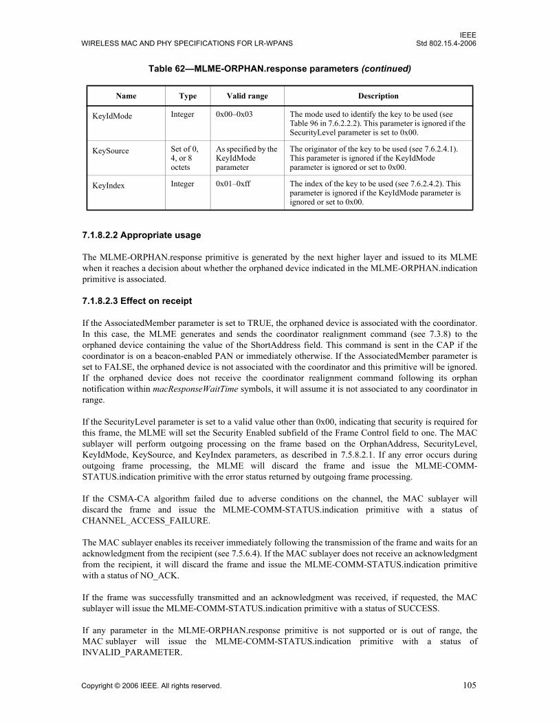
IEEEWIRELESS MAC AND PHY SPECIFICATIONS FOR LR-WPANS Std 802.15.4-2006
7.1.8.2.2 Appropriate usage
The MLME-ORPHAN.response primitive is generated by the next higher layer and issued to its MLMEwhen it reaches a decision about whether the orphaned device indicated in the MLME-ORPHAN.indicationprimitive is associated.
7.1.8.2.3 Effect on receipt
If the AssociatedMember parameter is set to TRUE, the orphaned device is associated with the coordinator.In this case, the MLME generates and sends the coordinator realignment command (see 7.3.8) to theorphaned device containing the value of the ShortAddress field. This command is sent in the CAP if thecoordinator is on a beacon-enabled PAN or immediately otherwise. If the AssociatedMember parameter isset to FALSE, the orphaned device is not associated with the coordinator and this primitive will be ignored.If the orphaned device does not receive the coordinator realignment command following its orphannotification within macResponseWaitTime symbols, it will assume it is not associated to any coordinator inrange.
If the SecurityLevel parameter is set to a valid value other than 0x00, indicating that security is required forthis frame, the MLME will set the Security Enabled subfield of the Frame Control field to one. The MACsublayer will perform outgoing processing on the frame based on the OrphanAddress, SecurityLevel,KeyIdMode, KeySource, and KeyIndex parameters, as described in 7.5.8.2.1. If any error occurs duringoutgoing frame processing, the MLME will discard the frame and issue the MLME-COMM-STATUS.indication primitive with the error status returned by outgoing frame processing.
If the CSMA-CA algorithm failed due to adverse conditions on the channel, the MAC sublayer willdiscard the frame and issue the MLME-COMM-STATUS.indication primitive with a status ofCHANNEL_ACCESS_FAILURE.
The MAC sublayer enables its receiver immediately following the transmission of the frame and waits for anacknowledgment from the recipient (see 7.5.6.4). If the MAC sublayer does not receive an acknowledgmentfrom the recipient, it will discard the frame and issue the MLME-COMM-STATUS.indication primitivewith a status of NO_ACK.
If the frame was successfully transmitted and an acknowledgment was received, if requested, the MACsublayer will issue the MLME-COMM-STATUS.indication primitive with a status of SUCCESS.
If any parameter in the MLME-ORPHAN.response primitive is not supported or is out of range, theMAC sublayer will issue the MLME-COMM-STATUS.indication primitive with a status ofINVALID_PARAMETER.
KeyIdMode Integer 0x00–0x03 The mode used to identify the key to be used (see Table 96 in 7.6.2.2.2). This parameter is ignored if the SecurityLevel parameter is set to 0x00.
KeySource Set of 0, 4, or 8 octets
As specified by the KeyIdMode parameter
The originator of the key to be used (see 7.6.2.4.1). This parameter is ignored if the KeyIdMode parameter is ignored or set to 0x00.
KeyIndex Integer 0x01–0xff The index of the key to be used (see 7.6.2.4.2). This parameter is ignored if the KeyIdMode parameter is ignored or set to 0x00.
Table 62—MLME-ORPHAN.response parameters (continued)
Name Type Valid range Description
Copyright © 2006 IEEE. All rights reserved. 105

IEEEStd 802.15.4-2006 LOCAL AND METROPOLITAN AREA NETWORKS—PART 15.4:
7.1.8.3 Orphan notification message sequence chart
Figure 36 illustrates the sequence of messages necessary for a coordinator to issue a notification of anorphaned device.
7.1.9 Primitives for resetting the MAC sublayer
MLME-SAP reset primitives specify how to reset the MAC sublayer to its default values.
All devices shall provide an interface for these reset primitives.
7.1.9.1 MLME-RESET.request
The MLME-RESET.request primitive allows the next higher layer to request that the MLME performs areset operation.
7.1.9.1.1 Semantics of the service primitive
The semantics of the MLME-RESET.request primitive are as follows:
Table 63 specifies the parameter for the MLME-RESET.request primitive.
Table 63—MLME-RESET.request parameter
Name Type Valid range Description
SetDefaultPIB Boolean TRUE or FALSE If TRUE, the MAC sublayer is reset, and all MAC PIB attributes are set to their default values. If FALSE, the MAC sublayer is reset, but all MAC PIB attributes retain their values prior to the generation of the MLME-RESET.request primitive.
Figure 36—Message sequence chart for orphan notification
MLME-RESET.request (SetDefaultPIB)
106 Copyright © 2006 IEEE. All rights reserved.
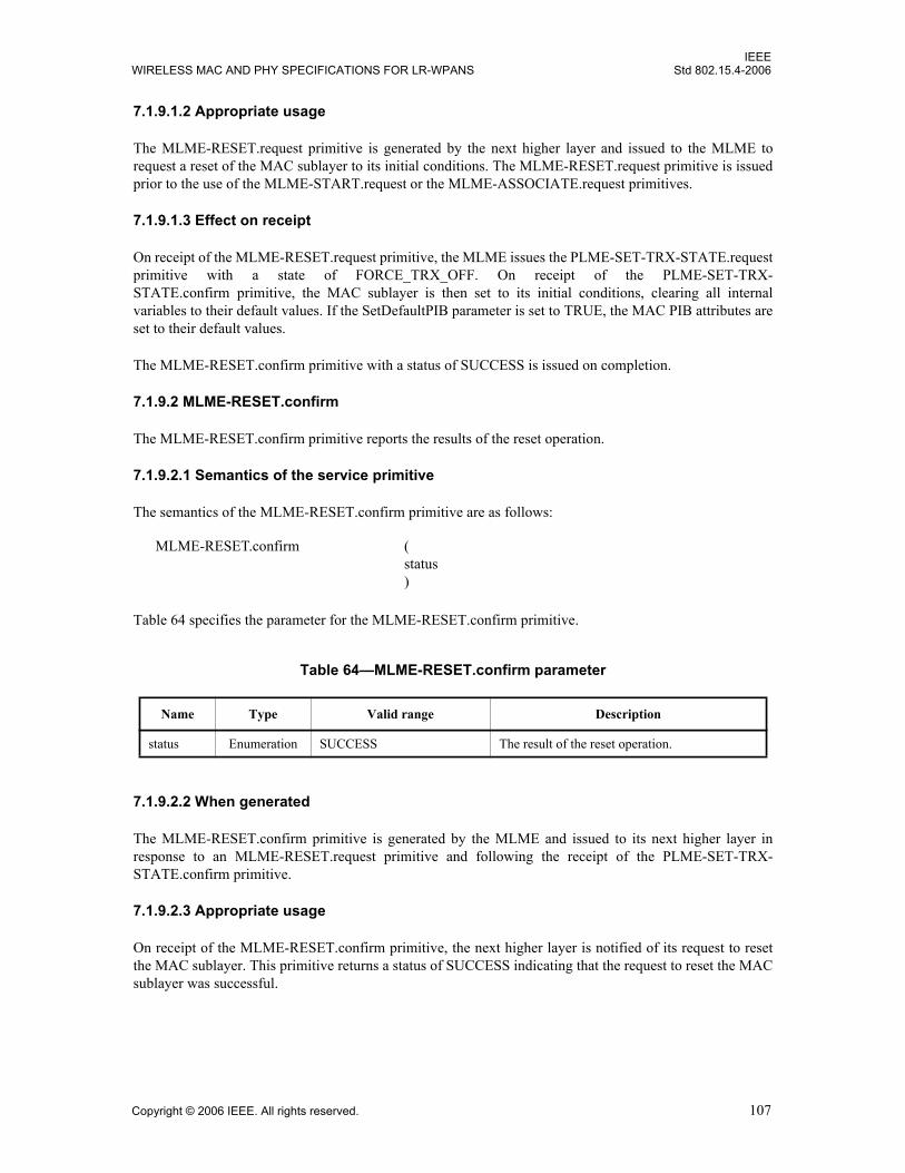
IEEEWIRELESS MAC AND PHY SPECIFICATIONS FOR LR-WPANS Std 802.15.4-2006
7.1.9.1.2 Appropriate usage
The MLME-RESET.request primitive is generated by the next higher layer and issued to the MLME torequest a reset of the MAC sublayer to its initial conditions. The MLME-RESET.request primitive is issuedprior to the use of the MLME-START.request or the MLME-ASSOCIATE.request primitives.
7.1.9.1.3 Effect on receipt
On receipt of the MLME-RESET.request primitive, the MLME issues the PLME-SET-TRX-STATE.requestprimitive with a state of FORCE_TRX_OFF. On receipt of the PLME-SET-TRX-STATE.confirm primitive, the MAC sublayer is then set to its initial conditions, clearing all internalvariables to their default values. If the SetDefaultPIB parameter is set to TRUE, the MAC PIB attributes areset to their default values.
The MLME-RESET.confirm primitive with a status of SUCCESS is issued on completion.
7.1.9.2 MLME-RESET.confirm
The MLME-RESET.confirm primitive reports the results of the reset operation.
7.1.9.2.1 Semantics of the service primitive
The semantics of the MLME-RESET.confirm primitive are as follows:
Table 64 specifies the parameter for the MLME-RESET.confirm primitive.
7.1.9.2.2 When generated
The MLME-RESET.confirm primitive is generated by the MLME and issued to its next higher layer inresponse to an MLME-RESET.request primitive and following the receipt of the PLME-SET-TRX-STATE.confirm primitive.
7.1.9.2.3 Appropriate usage
On receipt of the MLME-RESET.confirm primitive, the next higher layer is notified of its request to resetthe MAC sublayer. This primitive returns a status of SUCCESS indicating that the request to reset the MACsublayer was successful.
Table 64—MLME-RESET.confirm parameter
Name Type Valid range Description
status Enumeration SUCCESS The result of the reset operation.
MLME-RESET.confirm (status)
Copyright © 2006 IEEE. All rights reserved. 107
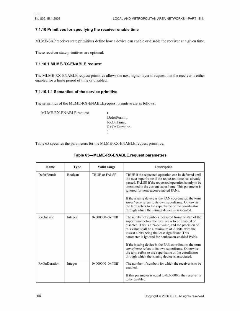
IEEEStd 802.15.4-2006 LOCAL AND METROPOLITAN AREA NETWORKS—PART 15.4:
7.1.10 Primitives for specifying the receiver enable time
MLME-SAP receiver state primitives define how a device can enable or disable the receiver at a given time.
These receiver state primitives are optional.
7.1.10.1 MLME-RX-ENABLE.request
The MLME-RX-ENABLE.request primitive allows the next higher layer to request that the receiver is eitherenabled for a finite period of time or disabled.
7.1.10.1.1 Semantics of the service primitive
The semantics of the MLME-RX-ENABLE.request primitive are as follows:
Table 65 specifies the parameters for the MLME-RX-ENABLE.request primitive.
Table 65—MLME-RX-ENABLE.request parameters
Name Type Valid range Description
DeferPermit Boolean TRUE or FALSE TRUE if the requested operation can be deferred until the next superframe if the requested time has already passed. FALSE if the requested operation is only to be attempted in the current superframe. This parameter is ignored for nonbeacon-enabled PANs.
If the issuing device is the PAN coordinator, the term superframe refers to its own superframe. Otherwise, the term refers to the superframe of the coordinator through which the issuing device is associated.
RxOnTime Integer 0x000000–0xffffff The number of symbols measured from the start of the superframe before the receiver is to be enabled or disabled. This is a 24-bit value, and the precision of this value shall be a minimum of 20 bits, with the lowest 4 bits being the least significant. This parameter is ignored for nonbeacon-enabled PANs.
If the issuing device is the PAN coordinator, the term superframe refers to its own superframe. Otherwise, the term refers to the superframe of the coordinator through which the issuing device is associated.
RxOnDuration Integer 0x000000–0xffffff The number of symbols for which the receiver is to be enabled.
If this parameter is equal to 0x000000, the receiver is to be disabled.
MLME-RX-ENABLE.request (DeferPermit,RxOnTime,RxOnDuration)
108 Copyright © 2006 IEEE. All rights reserved.
IEEEWIRELESS MAC AND PHY SPECIFICATIONS FOR LR-WPANS Std 802.15.4-2006
7.1.10.1.2 Appropriate usage
The MLME-RX-ENABLE.request primitive is generated by the next higher layer and issued to the MLMEto enable the receiver for a fixed duration, at a time relative to the start of the current or next superframe ona beacon-enabled PAN or immediately on a nonbeacon-enabled PAN. This primitive may also be generatedto cancel a previously generated request to enable the receiver. The receiver is enabled or disabled exactlyonce per primitive request.
7.1.10.1.3 Effect on receipt
The MLME will treat the request to enable or disable the receiver as secondary to other responsibilities ofthe device (e.g., GTSs, coordinator beacon tracking, beacon transmissions). When the primitive is issued toenable the receiver, the device will enable its receiver until either the device has a conflicting responsibilityor the time specified by RxOnDuration has expired. In the case of a conflicting responsibility, the devicewill interrupt the receive operation. After the completion of the interrupting operation, the RxOnDurationwill be checked to determine whether the time has expired. If so, the operation is complete. If not, thereceiver is re-enabled until either the device has another conflicting responsibility or the time specified byRxOnDuration has expired. When the primitive is issued to disable the receiver, the device will disable itsreceiver unless the device has a conflicting responsibility.
On a nonbeacon-enabled PAN, the MLME ignores the DeferPermit and RxOnTime parameters and requeststhat the PHY enable or disable the receiver immediately. If the request is to enable the receiver, the receiverwill remain enabled until RxOnDuration symbols have elapsed.
Before attempting to enable the receiver on a beacon-enabled PAN, the MLME first determines whether(RxOnTime + RxOnDuration) is less than the beacon interval, as defined by macBeaconOrder. If(RxOnTime + RxOnDuration) is not less than the beacon interval, the MLME issues the MLME-RX-ENABLE.confirm primitive with a status of ON_TIME_TOO_LONG.
The MLME then determines whether the receiver can be enabled in the current superframe. The PANcoordinator issuing this primitive makes the determination based on its own superframe. A device that is notthe PAN coordinator makes the determination based on the superframe of the coordinator through which it isassociated. If the current number of symbols measured from the start of the superframe is less than(RxOnTime – aTurnaroundTime), the MLME attempts to enable the receiver in the current superframe. Ifthe current number of symbols measured from the start of the superframe is greater than or equal to(RxOnTime – aTurnaroundTime) and DeferPermit is equal to TRUE, the MLME defers until the nextsuperframe and attempts to enable the receiver in that superframe. Otherwise, if the MLME cannot enablethe receiver in the current superframe and is not permitted to defer the receive operation until the nextsuperframe, the MLME issues the MLME-RX-ENABLE.confirm primitive with a status of PAST_TIME.
If the RxOnDuration parameter is equal to zero, the MLME requests that the PHY disable its receiver.
If any parameter in the MLME-RX-ENABLE.request primitive is not supported or is out of range, the MACsublayer will issue the MLME-RX-ENABLE.confirm primitive with a status of INVALID_PARAMETER.
If the request to enable or disable the receiver was successful, the MLME issues the MLME-RX-ENABLE.confirm primitive with a status of SUCCESS.
Copyright © 2006 IEEE. All rights reserved. 109

IEEEStd 802.15.4-2006 LOCAL AND METROPOLITAN AREA NETWORKS—PART 15.4:
7.1.10.2 MLME-RX-ENABLE.confirm
The MLME-RX-ENABLE.confirm primitive reports the results of the attempt to enable or disable thereceiver.
7.1.10.2.1 Semantics of the service primitive
The semantics of the MLME-RX-ENABLE.confirm primitive are as follows:
Table 66 specifies the parameter for the MLME-RX-ENABLE.confirm primitive.
7.1.10.2.2 When generated
The MLME-RX-ENABLE.confirm primitive is generated by the MLME and issued to its next higher layerin response to an MLME-RX-ENABLE.request primitive.
7.1.10.2.3 Appropriate usage
On receipt of the MLME-RX-ENABLE.confirm primitive, the next higher layer is notified of its request toenable or disable the receiver. This primitive returns a status of either SUCCESS, if the request to enable ordisable the receiver was successful, or the appropriate error code. The status values are fully described in7.1.10.1.3.
7.1.10.3 Message sequence chart for changing the state of the receiver
Figure 37 illustrates the sequence of messages necessary for enabling the receiver for a fixed duration whenthe device does not have any conflicting responsibilities. Figure 37a illustrates the case for a beacon-enabledPAN where it is assumed both that the MLME-RX-ENABLE.request has been received by the MLMEwithout sufficient time available to enable the receiver in the current superframe and that the DeferPermitparameter is TRUE. Figure 37b illustrates the case for a nonbeacon-enabled PAN where the receiver isenabled immediately.
Table 66—MLME-RX-ENABLE.confirm parameter
Name Type Valid range Description
status Enumeration SUCCESS,PAST_TIME,ON_TIME_TOO_LONG orINVALID_PARAMETER
The result of the request to enable or disable the receiver.
MLME-RX-ENABLE.confirm (status)
110 Copyright © 2006 IEEE. All rights reserved.

IEEEWIRELESS MAC AND PHY SPECIFICATIONS FOR LR-WPANS Std 802.15.4-2006
7.1.11 Primitives for channel scanning
MLME-SAP scan primitives define how a device can determine the energy usage or the presence or absenceof PANs in a communications channel.
All devices shall provide an interface for these scan primitives.
7.1.11.1 MLME-SCAN.request
The MLME-SCAN.request primitive is used to initiate a channel scan over a given list of channels. A devicecan use a channel scan to measure the energy on the channel, search for the coordinator with which itassociated, or search for all coordinators transmitting beacon frames within the POS of the scanning device.
Figure 37—Message sequence chart for changing the state of the receiver
Next higherlayer MLME
MLME-RX-ENABLE.request(DeferPermit, RxOnTime, RxOnDuration)
MLME-RX-ENABLE.confirm(SUCCESS)
PD-DATA.indication (Beacon frame)
(RxOnTime - aTurnaroundTime)PLME-SET-TRX-STATE.request
(RX_ON)
PLME-SET-TRX-STATE.confirm(SUCCESS)
(RxOnDuration)PLME-SET-TRX-STATE.request
(TRX_OFF)
PLME-SET-TRX-STATE.confirm(SUCCESS)
MLME-RX-ENABLE.request(DeferPermit, RxOnTime, RxOnDuration)
MLME-RX-ENABLE.confirm(SUCCESS)
PLME-SET-TRX-STATE.request(RX_ON)
PLME-SET-TRX-STATE.confirm(SUCCESS)
(RxOnDuration)PLME-SET-TRX-STATE.request
(TRX_OFF)
PLME-SET-TRX-STATE.confirm(SUCCESS)
a)
b)
Copyright © 2006 IEEE. All rights reserved. 111

IEEEStd 802.15.4-2006 LOCAL AND METROPOLITAN AREA NETWORKS—PART 15.4:
7.1.11.1.1 Semantics of the service primitive
The semantics of the MLME-SCAN.request primitive are as follows:
Table 67 specifies the parameters for the MLME-SCAN.request primitive.
Table 67—MLME-SCAN.request parameters
Name Type Valid range Description
ScanType Integer 0x00–0x03 Indicates the type of scan performed:
0x00 = ED scan (optional for RFD).0x01 = active scan (optional for RFD).0x02 = passive scan.0x03 = orphan scan.
ScanChannels Bitmap 27-bit field The 27 bits (b0, b1,... b26) indicate which channels are to be scanned (1 = scan, 0 = do not scan) for each of the 27 channels supported by the ChannelPage parameter.
ScanDuration Integer 0–14 A value used to calculate the length of time to spend scanning each channel for ED, active, and passive scans. This parameter is ignored for orphan scans.
The time spent scanning each channel is [aBaseSuperframeDuration * (2n + 1)] symbols, where n is the value of the ScanDuration parameter.
ChannelPage Integer 0–31 The channel page on which to perform the scan (see 6.1.2).
SecurityLevel Integer 0x00–0x07 The security level to be used (see Table 95 in 7.6.2.2.1).
KeyIdMode Integer 0x00–0x03 The mode used to identify the key to be used (see Table 96 in 7.6.2.2.2). This parameter is ignored if the SecurityLevel parameter is set to 0x00.
MLME-SCAN.request (ScanType,ScanChannels,ScanDuration,ChannelPage,SecurityLevel,KeyIdMode,KeySource,KeyIndex)
112 Copyright © 2006 IEEE. All rights reserved.
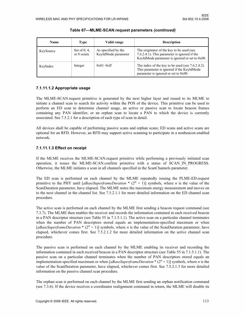
IEEEWIRELESS MAC AND PHY SPECIFICATIONS FOR LR-WPANS Std 802.15.4-2006
7.1.11.1.2 Appropriate usage
The MLME-SCAN.request primitive is generated by the next higher layer and issued to its MLME toinitiate a channel scan to search for activity within the POS of the device. This primitive can be used toperform an ED scan to determine channel usage, an active or passive scan to locate beacon framescontaining any PAN identifier, or an orphan scan to locate a PAN to which the device is currentlyassociated. See 7.5.2.1 for a description of each type of scan in detail.
All devices shall be capable of performing passive scans and orphan scans; ED scans and active scans areoptional for an RFD. However, an RFD may support active scanning to participate in a nonbeacon-enablednetwork.
7.1.11.1.3 Effect on receipt
If the MLME receives the MLME-SCAN.request primitive while performing a previously initiated scanoperation, it issues the MLME-SCAN.confirm primitive with a status of SCAN_IN_PROGRESS.Otherwise, the MLME initiates a scan in all channels specified in the ScanChannels parameter.
The ED scan is performed on each channel by the MLME repeatedly issuing the PLME-ED.requestprimitive to the PHY until [aBaseSuperframeDuration * (2n + 1)] symbols, where n is the value of theScanDuration parameter, have elapsed. The MLME notes the maximum energy measurement and moves onto the next channel in the channel list. See 7.5.2.1.1 for more detailed information on the ED channel scanprocedure.
The active scan is performed on each channel by the MLME first sending a beacon request command (see7.3.7). The MLME then enables the receiver and records the information contained in each received beaconin a PAN descriptor structure (see Table 55 in 7.1.5.1.1). The active scan on a particular channel terminateswhen the number of PAN descriptors stored equals an implementation-specified maximum or when[aBaseSuperframeDuration * (2n + 1)] symbols, where n is the value of the ScanDuration parameter, haveelapsed, whichever comes first. See 7.5.2.1.2 for more detailed information on the active channel scanprocedure.
The passive scan is performed on each channel by the MLME enabling its receiver and recording theinformation contained in each received beacon in a PAN descriptor structure (see Table 55 in 7.1.5.1.1). Thepassive scan on a particular channel terminates when the number of PAN descriptors stored equals animplementation-specified maximum or when [aBaseSuperframeDuration * (2n + 1)] symbols, where n is thevalue of the ScanDuration parameter, have elapsed, whichever comes first. See 7.5.2.1.3 for more detailedinformation on the passive channel scan procedure.
The orphan scan is performed on each channel by the MLME first sending an orphan notification command(see 7.3.6). If the device receives a coordinator realignment command in return, the MLME will disable its
KeySource Set of 0, 4, or 8 octets
As specified by the KeyIdMode parameter
The originator of the key to be used (see 7.6.2.4.1). This parameter is ignored if the KeyIdMode parameter is ignored or set to 0x00.
KeyIndex Integer 0x01–0xff The index of the key to be used (see 7.6.2.4.2). This parameter is ignored if the KeyIdMode parameter is ignored or set to 0x00.
Table 67—MLME-SCAN.request parameters (continued)
Name Type Valid range Description
Copyright © 2006 IEEE. All rights reserved. 113

IEEEStd 802.15.4-2006 LOCAL AND METROPOLITAN AREA NETWORKS—PART 15.4:
receiver. Otherwise, the scan is repeated on the next channel in the channel list. See 7.5.2.1.4 for moredetailed information on the orphan channel scan procedure.
The SecurityLevel, KeyIdMode, KeySource, and KeyIndex parameters are used only in an orphan scan.
If the SecurityLevel parameter is set to a valid value other than 0x00, indicating that security is required forthis frame, the MLME will set the Security Enabled subfield of the Frame Control field to one. The MACsublayer will perform outgoing processing on the frame based on macCoordExtendedAddress, theSecurityLevel, KeyIdMode, KeySource, and KeyIndex parameters, as described in 7.5.8.2.1. If any erroroccurs during outgoing frame processing, the MLME will discard the frame and issue the MLME-SCAN.confirm primitive with the error status returned by outgoing frame processing.
The results of an ED scan are recorded in a list of ED values and reported to the next higher layer throughthe MLME-SCAN.confirm primitive with a status of SUCCESS.
The results of an active or passive scan are reported to the next higher layer through the MLME-SCAN.confirm primitive. If the scan is successful and macAutoRequest is set to TRUE, the primitive resultswill include a set of PAN descriptor values. If the scan is successful and macAutoRequest is set to FALSE,the primitive results will contain a null set of PAN descriptor values; each PAN descriptor value will be sentindividually to the next higher layer using separate MLME-BEACON-NOTIFY (see 7.1.5.1) primitives. Inboth cases, the MLME-SCAN.confirm primitive will contain a list of unscanned channels and a status ofSUCCESS.
If, during an active scan, the MLME is unable to transmit a beacon request command on a channel specifiedby the ScanChannels parameter due to a channel access failure, the channel will appear in the list ofunscanned channels returned by the MLME-SCAN.confirm primitive. If the MLME was able to send abeacon request command on at least one of the channels but no beacons were found, the MLME-SCAN.confirm primitive will contain a null set of PAN descriptor values, regardless of the value ofmacAutoRequest, and a status of NO_BEACON.
The results of an orphan scan are reported to the next higher layer through the MLME-SCAN.confirmprimitive. If successful, the MLME-SCAN.confirm primitive will contain a status of SUCCESS. If theMLME is unable to transmit an orphan notification command on a channel specified by the ScanChannelsparameter due to a channel access failure, the channel will appear in the list of unscanned channels returnedby the MLME-SCAN.confirm primitive. If the MLME was able to send an orphan notification command onat least one of the channels but the device did not receive a coordinator realignment command, the MLME-SCAN.confirm primitive will contain a status of NO_BEACON. In this case, the PANDescriptorList andEnergyDetectList parameters of the MLME-SCAN.confirm primitive are null.
If, during an ED, active, or passive scan, the implementation-specified maximum is reached thus terminatingthe scan procedure, the MAC sublayer will issue the MLME-SCAN.confirm primitive with a status ofLIMIT_REACHED.
If any parameter in the MLME-SCAN.request primitive is not supported or is out of range, the MACsublayer will issue the MLME-SCAN.confirm primitive with a status of INVALID_PARAMETER.
7.1.11.2 MLME-SCAN.confirm
The MLME-SCAN.confirm primitive reports the result of the channel scan request.
7.1.11.2.1 Semantics of the service primitive
The semantics of the MLME-SCAN.confirm primitive are as follows:
114 Copyright © 2006 IEEE. All rights reserved.

IEEEWIRELESS MAC AND PHY SPECIFICATIONS FOR LR-WPANS Std 802.15.4-2006
Table 68 specifies the parameters for the MLME-SCAN.confirm primitive.
Table 68—MLME-SCAN.confirm parameters
Name Type Valid range Description
status Enumeration SUCCESS, LIMIT_REACHED, NO_BEACON, SCAN_IN_PROGRESS,COUNTER_ERROR, FRAME_TOO_LONG, UNAVAILABLE_KEY, UNSUPPORTED_SECURITY or INVALID_PARAMETER
The status of the scan request.
ScanType Integer 0x00–0x03 Indicates the type of scan performed:
0x00 = ED scan (optional for RFD).0x01 = active scan (optional for RFD).0x02 = passive scan.0x03 = orphan scan.
ChannelPage Integer 0–31 The channel page on which the scan was performed (see 6.1.2).
UnscannedChannels Bitmap 27 bit field Indicates which channels given in the request were not scanned (1 = not scanned, 0 = scanned or not requested). This parameter is not valid for ED scans.
ResultListSize Integer Implementation specific The number of elements returned in the appropriate result lists. This value is zero for the result of an orphan scan.
EnergyDetectList List of integers 0x00–0xff for each integer The list of energy measurements, one for each channel searched during an ED scan. This parameter is null for active, passive, and orphan scans.
PANDescriptorList List ofPAN descriptor values
See Table 55 The list of PAN descriptors, one for each beacon found during an active or passive scan if macAutoRequest is set to TRUE. This parameter is null for ED and orphan scans or when macAutoRequest is set to FALSE during an active or passive scan.
MLME-SCAN.confirm (status,ScanType,ChannelPage,UnscannedChannels,ResultListSize,EnergyDetectList,PANDescriptorList)
Copyright © 2006 IEEE. All rights reserved. 115

IEEEStd 802.15.4-2006 LOCAL AND METROPOLITAN AREA NETWORKS—PART 15.4:
7.1.11.2.2 When generated
The MLME-SCAN.confirm primitive is generated by the MLME and issued to its next higher layer whenthe channel scan initiated with the MLME-SCAN.request primitive has completed. If the MLME-SCAN.request primitive requested an active, passive, or orphan scan, the EnergyDetectList parameter willbe null. If the MLME-SCAN.request primitive requested an ED or orphan scan, the PANDescriptorListparameter will be null; this is also the case if the MLME-SCAN.request primitive requested an active orpassive scan with macAutoRequest set to FALSE. If the MLME-SCAN.request primitive requested anorphan scan, the ResultListSize parameter will be set to zero.
The MLME-SCAN.confirm primitive returns a status of either SUCCESS, indicating that the requested scanwas successful, or the appropriate error code. The status values are fully described in 7.1.11.1.3 andsubclauses referenced by 7.1.11.1.3.
7.1.11.2.3 Appropriate usage
On receipt of the MLME-SCAN.confirm primitive, the next higher layer is notified of the results of the scanprocedure. If the requested scan was successful, the status parameter will be set to SUCCESS. Otherwise,the status parameter indicates the error.
7.1.11.3 Channel scan message sequence charts
Figure 79, Figure 82, Figure 83, and Figure 86 (see 7.7) illustrate the sequence of messages necessary toperform an ED scan, a passive scan, an active scan, and an orphan scan, respectively. These figures includesteps taken by the PHY.
7.1.12 Communication status primitive
The MLME-SAP communication status primitive defines how the MLME communicates to the next higherlayer about transmission status, when the transmission was instigated by a response primitive, and aboutsecurity errors on incoming packets.
All devices shall provide an interface for this communication status primitive.
7.1.12.1 MLME-COMM-STATUS.indication
The MLME-COMM-STATUS.indication primitive allows the MLME to indicate a communications status.
7.1.12.1.1 Semantics of the service primitive
The semantics of the MLME-COMM-STATUS.indication primitive are as follows:
MLME-COMM-STATUS.indication (PANId,SrcAddrMode,SrcAddr,DstAddrMode,DstAddr,status,SecurityLevel,KeyIdMode,KeySource,KeyIndex)
116 Copyright © 2006 IEEE. All rights reserved.

IEEEWIRELESS MAC AND PHY SPECIFICATIONS FOR LR-WPANS Std 802.15.4-2006
Table 69 specifies the parameters for the MLME-COMM-STATUS.indication primitive.
Table 69—MLME-COMM-STATUS.indication parameters
Name Type Valid range Description
PANId Integer 0x0000–0xffff The 16-bit PAN identifier of the device from which the frame was received or to which the frame was being sent.
SrcAddrMode Integer 0x00–0x03 The source addressing mode for this primitive. This value can take one of the following values:
0 = no address (addressing fields omitted).0x01 = reserved.0x02 = 16-bit short address.0x03 = 64-bit extended address.
SrcAddr Device address
As specified by theSrcAddrModeparameter
The individual device address of the entity from which the frame causing the error originated.
DstAddrMode Integer 0x00–0x03 The destination addressing mode for this primitive. This value can take one of the following values:
0x00 = no address (addressing fields omitted).0x01 = reserved.0x02 = 16-bit short address.0x03 = 64-bit extended address.
DstAddr Device address
As specified by theDstAddrModeparameter
The individual device address of the device for which the frame was intended.
status Enumeration SUCCESS,TRANSACTION_OVERFLOW,TRANSACTION_EXPIRED,CHANNEL_ACCESS_FAILURE,NO_ACK, COUNTER_ERROR, FRAME_TOO_LONG, IMPROPER_KEY_TYPE, IMPROPER_SECURITY_LEVEL, SECURITY_ERROR, UNAVAILABLE_KEY, UNSUPPORTED_LEGACY, UNSUPPORTED_SECURITY orINVALID_PARAMETER
The communications status.
Copyright © 2006 IEEE. All rights reserved. 117

IEEEStd 802.15.4-2006 LOCAL AND METROPOLITAN AREA NETWORKS—PART 15.4:
SecurityLevel Integer 0x00–0x07 If the primitive was generated following a transmission instigated through a response primitive:
The security level to be used (see Table 95 in 7.6.2.2.1).
If the primitive was generated on receipt of a frame that generates an error in its security processing:
The security level purportedly used by the received frame (see Table 95 in 7.6.2.2.1).
KeyIdMode Integer 0x00–0x03 If the primitive was generated following a transmission instigated through a response primitive:
The mode used to identify the key to be used (see Table 96 in 7.6.2.2.2). This parameter is ignored if the SecurityLevel parameter is set to 0x00.
If the primitive was generated on receipt of a frame that generates an error in its security processing:
The mode used to identify the key purportedly used by the originator of the received frame (see Table 96 in 7.6.2.2.2). This parameter is invalid if the SecurityLevel parameter is set to 0x00.
KeySource Set of 0, 4, or 8 octets
As specified by the KeyIdMode parameter
If the primitive was generated following a transmission instigated through a response primitive:
The originator of the key to be used (see 7.6.2.4.1). This parameter is ignored if the KeyIdMode parameter is ignored or set to 0x00.
If the primitive was generated on receipt of a frame that generates an error in its security processing:
The originator of the key purportedly used by the originator of the received frame (see 7.6.2.4.1). This parameter is invalid if the KeyIdMode parameter is invalid or set to 0x00.
Table 69—MLME-COMM-STATUS.indication parameters (continued)
Name Type Valid range Description
118 Copyright © 2006 IEEE. All rights reserved.

IEEEWIRELESS MAC AND PHY SPECIFICATIONS FOR LR-WPANS Std 802.15.4-2006
7.1.12.1.2 When generated
The MLME-COMM-STATUS.indication primitive is generated by the MLME and issued to its next higherlayer either following a transmission instigated through a response primitive or on receipt of a frame thatgenerates an error in its security processing (see 7.5.8.2.3).
The MLME-COMM-STATUS.indication primitive is generated by the MAC sublayer entity followingeither the MLME-ASSOCIATE.response primitive or the MLME-ORPHAN.response primitive. Thisprimitive returns a status of either SUCCESS, indicating that the request to transmit was successful, an errorcode of TRANSACTION_OVERFLOW, TRANSACTION_EXPIRED, CHANNEL_ACCESS_FAILURE,NO_ACK or INVALID_PARAMETER (these status values are fully described in 7.1.3.3.3 and 7.1.8.2.3),or an error code resulting from failed security processing (these status values are fully described in 7.5.8.2.1and 7.5.8.2.3).
7.1.12.1.3 Appropriate usage
On receipt of the MLME-COMM-STATUS.indication primitive, the next higher layer is notified of thecommunication status of a transmission or notified of an error that has occurred during the secure processingof incoming frame.
7.1.13 Primitives for writing PIB attributes
MLME-SAP set primitives define how PIB attributes may be written.
All devices shall provide an interface for these set primitives.
7.1.13.1 MLME-SET.request
The MLME-SET.request primitive attempts to write the given value to the indicated PIB attribute.
KeyIndex Integer 0x01–0xff If the primitive was generated following a transmission instigated through a response primitive:
The index of the key to be used (see 7.6.2.4.2). This parameter is ignored if the KeyIdMode parameter is ignored or set to 0x00.
If the primitive was generated on receipt of a frame that generates an error in its security processing:
The index of the key purportedly used by the originator of the received frame (see 7.6.2.4.2). This parameter is invalid if the KeyIdMode parameter is invalid or set to 0x00.
Table 69—MLME-COMM-STATUS.indication parameters (continued)
Name Type Valid range Description
Copyright © 2006 IEEE. All rights reserved. 119
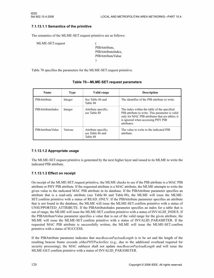
IEEEStd 802.15.4-2006 LOCAL AND METROPOLITAN AREA NETWORKS—PART 15.4:
7.1.13.1.1 Semantics of the primitive
The semantics of the MLME-SET.request primitive are as follows:
Table 70 specifies the parameters for the MLME-SET.request primitive.
7.1.13.1.2 Appropriate usage
The MLME-SET.request primitive is generated by the next higher layer and issued to its MLME to write theindicated PIB attribute.
7.1.13.1.3 Effect on receipt
On receipt of the MLME-SET.request primitive, the MLME checks to see if the PIB attribute is a MAC PIBattribute or PHY PIB attribute. If the requested attribute is a MAC attribute, the MLME attempts to write thegiven value to the indicated MAC PIB attribute in its database. If the PIBAttribute parameter specifies anattribute that is a read-only attribute (see Table 86 and Table 88), the MLME will issue the MLME-SET.confirm primitive with a status of READ_ONLY. If the PIBAttribute parameter specifies an attributethat is not found in the database, the MLME will issue the MLME-SET.confirm primitive with a status ofUNSUPPORTED_ATTRIBUTE. If the PIBAttributeIndex parameter specifies an index for a table that isout of range, the MLME will issue the MLME-SET.confirm primitive with a status of INVALID_INDEX. Ifthe PIBAttributeValue parameter specifies a value that is out of the valid range for the given attribute, theMLME will issue the MLME-SET.confirm primitive with a status of INVALID_PARAMETER. If therequested MAC PIB attribute is successfully written, the MLME will issue the MLME-SET.confirmprimitive with a status of SUCCESS.
If the PIBAttribute parameter indicates that macBeaconPayloadLength is to be set and the length of theresulting beacon frame exceeds aMaxPHYPacketSize (e.g., due to the additional overhead required forsecurity processing), the MAC sublayer shall not update macBeaconPayloadLength and will issue theMLME-GET.confirm primitive with a status of INVALID_PARAMETER.
Table 70—MLME-SET.request parameters
Name Type Valid range Description
PIBAttribute Integer See Table 86 and Table 88
The identifier of the PIB attribute to write.
PIBAttributeIndex Integer Attribute specific;see Table 88
The index within the table of the specified PIB attribute to write. This parameter is valid only for MAC PIB attributes that are tables; it is ignored when accessing PHY PIB attributes.
PIBAttributeValue Various Attribute specific;see Table 86 and Table 88
The value to write to the indicated PIB attribute.
MLME-SET.request (PIBAttribute,PIBAttributeIndex,PIBAttributeValue)
120 Copyright © 2006 IEEE. All rights reserved.

IEEEWIRELESS MAC AND PHY SPECIFICATIONS FOR LR-WPANS Std 802.15.4-2006
If the requested attribute is a PHY PIB attribute, the request is passed to the PHY by issuing the PLME-SET.request primitive. Once the MLME receives the PLME-SET.confirm primitive, it will translate thereceived status value because the status values used by the PHY are not the same as those used by theMLME (e.g., the status values for SUCCESS are 0x00 and 0x07 in the MAC and PHY enumeration tables,respectively). Following the translation, the MLME will issue the MLME-SET.confirm primitive to the nexthigher layer with the status parameter resulting from the translation and the PIBAttribute parameter equal tothat returned by the PLME primitive.
7.1.13.2 MLME-SET.confirm
The MLME-SET.confirm primitive reports the results of an attempt to write a value to a PIB attribute.
7.1.13.2.1 Semantics of the service primitive
The semantics of the MLME-SET.confirm primitive are as follows:
Table 71 specifies the parameters for the MLME-SET.confirm primitive.
7.1.13.2.2 When generated
The MLME-SET.confirm primitive is generated by the MLME and issued to its next higher layer inresponse to an MLME-SET.request primitive. The MLME-SET.confirm primitive returns a status of eitherSUCCESS, indicating that the requested value was written to the indicated PIB attribute, or the appropriateerror code. The status values are fully described in 7.1.13.1.3.
7.1.13.2.3 Appropriate usage
On receipt of the MLME-SET.confirm primitive, the next higher layer is notified of the result of its requestto set the value of a PIB attribute. If the requested value was written to the indicated PIB attribute, the statusparameter will be set to SUCCESS. Otherwise, the status parameter indicates the error.
Table 71—MLME-SET.confirm parameters
Name Type Valid range Description
status Enumeration SUCCESS, READ_ONLY, UNSUPPORTED_ATTRIBUTE,INVALID_INDEX or INVALID_PARAMETER
The result of the request to write the PIB attribute.
PIBAttribute Integer See Table 86 and Table 88 The identifier of the PIB attribute that was written.
PIBAttributeIndex Integer Attribute specific;see Table 88
The index within the table of the specified PIB attribute to write. This parameter is valid only for MAC PIB attributes that are tables; it is ignored when accessing PHY PIB attributes.
MLME-SET.confirm (status,PIBAttribute,PIBAttributeIndex)
Copyright © 2006 IEEE. All rights reserved. 121
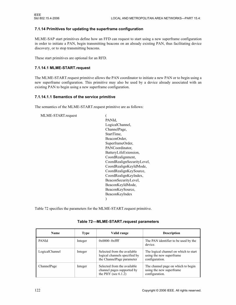
IEEEStd 802.15.4-2006 LOCAL AND METROPOLITAN AREA NETWORKS—PART 15.4:
7.1.14 Primitives for updating the superframe configuration
MLME-SAP start primitives define how an FFD can request to start using a new superframe configurationin order to initiate a PAN, begin transmitting beacons on an already existing PAN, thus facilitating devicediscovery, or to stop transmitting beacons.
These start primitives are optional for an RFD.
7.1.14.1 MLME-START.request
The MLME-START.request primitive allows the PAN coordinator to initiate a new PAN or to begin using anew superframe configuration. This primitive may also be used by a device already associated with anexisting PAN to begin using a new superframe configuration.
7.1.14.1.1 Semantics of the service primitive
The semantics of the MLME-START.request primitive are as follows:
Table 72 specifies the parameters for the MLME-START.request primitive.
Table 72—MLME-START.request parameters
Name Type Valid range Description
PANId Integer 0x0000–0xffff The PAN identifier to be used by the device.
LogicalChannel Integer Selected from the available logical channels specified by the ChannelPage parameter
The logical channel on which to start using the new superframe configuration.
ChannelPage Integer Selected from the available channel pages supported by the PHY (see 6.1.2)
The channel page on which to begin using the new superframe configuration.
MLME-START.request (PANId,LogicalChannel,ChannelPage,StartTime,BeaconOrder,SuperframeOrder,PANCoordinator,BatteryLifeExtension,CoordRealignment,CoordRealignSecurityLevel,CoordRealignKeyIdMode,CoordRealignKeySource,CoordRealignKeyIndex,BeaconSecurityLevel,BeaconKeyIdMode,BeaconKeySource,BeaconKeyIndex)
122 Copyright © 2006 IEEE. All rights reserved.

IEEEWIRELESS MAC AND PHY SPECIFICATIONS FOR LR-WPANS Std 802.15.4-2006
StartTime Integer 0x000000–0xffffff The time at which to begin transmitting beacons. If this parameter is equal to 0x000000, beacon transmissions will begin immediately. Otherwise, the specified time is relative to the received beacon of the coordinator with which the device synchronizes.
This parameter is ignored if either the BeaconOrder parameter has a value of 15 or the PANCoordinator parameter is TRUE.
The time is specified in symbols and is rounded to a backoff slot boundary. This is a 24-bit value, and the precision of this value shall be a minimum of 20 bits, with the lowest 4 bits being the least significant.
BeaconOrder Integer 0–15 How often the beacon is to be transmitted. A value of 15 indicates that the coordinator will not transmit periodic beacons.
See 7.5.1.1 for an explanation of the relationship between the beacon order and the beacon interval.
SuperframeOrder Integer 0–BO or 15 The length of the active portion of the superframe, including the beacon frame. If the BeaconOrder parameter (BO) has a value of 15, this parameter is ignored.
See 7.5.1.1 for an explanation of the relationship between the superframe order and the superframe duration.
PANCoordinator Boolean TRUE or FALSE If this value is TRUE, the device will become the PAN coordinator of a new PAN. If this value is FALSE, the device will begin using a new superframe configuration on the PAN with which it is associated.
BatteryLifeExtension Boolean TRUE or FALSE If this value is TRUE, the receiver of the beaconing device is disabled macBattLifeExtPeriods full backoff periods after the interframe spacing (IFS) period following the beacon frame. If this value is FALSE, the receiver of the beaconing device remains enabled for the entire CAP.
This parameter is ignored if the BeaconOrder parameter has a value of 15.
Table 72—MLME-START.request parameters (continued)
Name Type Valid range Description
Copyright © 2006 IEEE. All rights reserved. 123
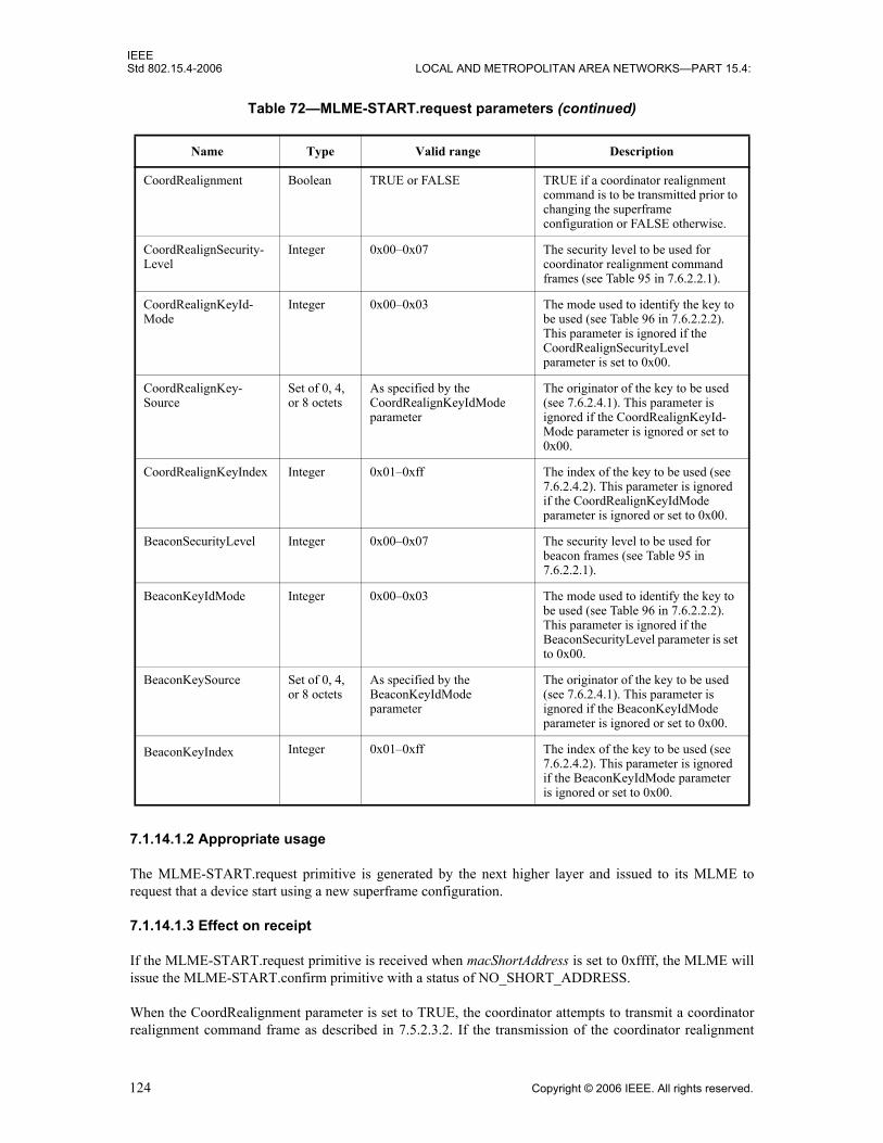
IEEEStd 802.15.4-2006 LOCAL AND METROPOLITAN AREA NETWORKS—PART 15.4:
7.1.14.1.2 Appropriate usage
The MLME-START.request primitive is generated by the next higher layer and issued to its MLME torequest that a device start using a new superframe configuration.
7.1.14.1.3 Effect on receipt
If the MLME-START.request primitive is received when macShortAddress is set to 0xffff, the MLME willissue the MLME-START.confirm primitive with a status of NO_SHORT_ADDRESS.
When the CoordRealignment parameter is set to TRUE, the coordinator attempts to transmit a coordinatorrealignment command frame as described in 7.5.2.3.2. If the transmission of the coordinator realignment
CoordRealignment Boolean TRUE or FALSE TRUE if a coordinator realignment command is to be transmitted prior to changing the superframe configuration or FALSE otherwise.
CoordRealignSecurity-Level
Integer 0x00–0x07 The security level to be used for coordinator realignment command frames (see Table 95 in 7.6.2.2.1).
CoordRealignKeyId-Mode
Integer 0x00–0x03 The mode used to identify the key to be used (see Table 96 in 7.6.2.2.2). This parameter is ignored if the CoordRealignSecurityLevel parameter is set to 0x00.
CoordRealignKey-Source
Set of 0, 4, or 8 octets
As specified by the CoordRealignKeyIdMode parameter
The originator of the key to be used (see 7.6.2.4.1). This parameter is ignored if the CoordRealignKeyId-Mode parameter is ignored or set to 0x00.
CoordRealignKeyIndex Integer 0x01–0xff The index of the key to be used (see 7.6.2.4.2). This parameter is ignored if the CoordRealignKeyIdMode parameter is ignored or set to 0x00.
BeaconSecurityLevel Integer 0x00–0x07 The security level to be used for beacon frames (see Table 95 in 7.6.2.2.1).
BeaconKeyIdMode Integer 0x00–0x03 The mode used to identify the key to be used (see Table 96 in 7.6.2.2.2). This parameter is ignored if the BeaconSecurityLevel parameter is set to 0x00.
BeaconKeySource Set of 0, 4, or 8 octets
As specified by the BeaconKeyIdMode parameter
The originator of the key to be used (see 7.6.2.4.1). This parameter is ignored if the BeaconKeyIdMode parameter is ignored or set to 0x00.
BeaconKeyIndex Integer 0x01–0xff The index of the key to be used (see 7.6.2.4.2). This parameter is ignored if the BeaconKeyIdMode parameter is ignored or set to 0x00.
Table 72—MLME-START.request parameters (continued)
Name Type Valid range Description
124 Copyright © 2006 IEEE. All rights reserved.

IEEEWIRELESS MAC AND PHY SPECIFICATIONS FOR LR-WPANS Std 802.15.4-2006
command fails due to a channel access failure, the MLME will not make any changes to the superframeconfiguration (i.e., no PIB attributes will be changed) and will issue an MLME-START.confirm with astatus of CHANNEL_ACCESS_FAILURE. If the coordinator realignment command is successfullytransmitted, the MLME updates the appropriate PIB parameters with the values of the BeaconOrder,SuperframeOrder, PANId, ChannelPage, and LogicalChannel parameters, as described in 7.5.2.3.4, and willissue an MLME-START.confirm with a status of SUCCESS.
When the CoordRealignment parameter is set to FALSE, the MLME updates the appropriate PIBparameters with the values of the BeaconOrder, SuperframeOrder, PANId, ChannelPage, andLogicalChannel parameters, as described in 7.5.2.3.4.
The address used by the coordinator in its beacon frames is determined by the current value ofmacShortAddress, which is set by the next higher layer before issuing this primitive. If the BeaconOrderparameter is less than 15, the MLME sets macBattLifeExt to the value of the BatteryLifeExtensionparameter. If the BeaconOrder parameter equals 15, the value of the BatteryLifeExtension parameter isignored.
If the SecurityLevel parameter is set to a valid value other than 0x00, indicating that security is required forthis frame, the MLME will set the Security Enabled subfield of the Frame Control field to one. The MACsublayer will perform outgoing processing on the frame, as described in 7.5.8.2.1. If the CoordRealignmentparameter is set to TRUE, the CoordRealignSecurityLevel, CoordRealignKeyIdMode, CoordRealignKey-Source, and CoordRealignKeyIndex parameters will be used to process the MAC command frame. If theBeaconOrder parameter indicates a beacon-enabled network, the BeaconSecurityLevel, BeaconKeyIdMode,BeaconKeySource, and BeaconKeyIndex parameters will be used to process the beacon frame. If any erroroccurs during outgoing frame processing, the MLME will discard the frame and issue the MLME-START.confirm primitive with the error status returned by outgoing frame processing.
If the length of the beacon frame exceeds aMaxPHYPacketSize (e.g., due to the additional overhead requiredfor security processing), the MAC sublayer shall discard the beacon frame and issue the MLME-START.confirm primitive with a status of FRAME_TOO_LONG.
The MLME shall ignore the StartTime parameter if the BeaconOrder parameter is equal to 15 because thisindicates a nonbeacon-enabled PAN. If the BeaconOrder parameter is less than 15, the MLME examines theStartTime parameter to determine the time to begin transmitting beacons; the time is defined in symbols andis rounded to a backoff slot boundary. If the PAN coordinator parameter is set to TRUE, the MLME ignoresthe StartTime parameter and begins beacon transmissions immediately. Setting the StartTime parameter to0x000000 also causes the MLME to begin beacon transmissions immediately. If the PANCoordinatorparameter is set to FALSE and the StartTime parameter is nonzero, the MLME calculates the beacontransmission time by adding StartTime symbols to the time, obtained from the local clock, when the MLMEreceives the beacon of the coordinator through which it is associated. If the time calculated causes theoutgoing superframe to overlap the incoming superframe, the MLME shall not begin beacon transmissions.In this case, the MLME issues the MLME-START.confirm primitive with a status ofSUPERFRAME_OVERLAP. Otherwise, the MLME then begins beacon transmissions when the currenttime, obtained from the local clock, equals the number of calculated symbols.
If the StartTime parameter is nonzero and the MLME is not currently tracking the beacon of the coordinatorthrough which it is associated, the MLME will issue the MLME-START.confirm primitive with a status ofTRACKING_OFF.
On completion of this procedure, the MLME responds with the MLME-START.confirm primitive. If theattempt to start using a new superframe configuration was successful, the status parameter will be set toSUCCESS. If any parameter is not supported or is out of range, the status parameter will be set toINVALID_PARAMETER.
Copyright © 2006 IEEE. All rights reserved. 125

IEEEStd 802.15.4-2006 LOCAL AND METROPOLITAN AREA NETWORKS—PART 15.4:
7.1.14.2 MLME-START.confirm
The MLME-START.confirm primitive reports the results of the attempt to start using a new superframeconfiguration.
7.1.14.2.1 Semantics of the service primitive
The semantics of the MLME-START.confirm primitive are as follows:
Table 73 specifies the parameters for the MLME-START.confirm primitive.
7.1.14.2.2 When generated
The MLME-START.confirm primitive is generated by the MLME and issued to its next higher layer inresponse to an MLME-START.request primitive. The MLME-START.confirm primitive returns a status ofeither SUCCESS, indicating that the MAC sublayer has started using the new superframe configuration, orthe appropriate error code. The status values are fully described in 7.1.14.1.3 and subclauses referenced by7.1.14.1.3.
7.1.14.2.3 Appropriate usage
On receipt of the MLME-START.confirm primitive, the next higher layer is notified of the result of itsrequest to start using a new superframe configuration. If the MAC sublayer has been successful, the statusparameter will be set to SUCCESS. Otherwise, the status parameter indicates the error.
7.1.14.3 Message sequence chart for updating the superframe configuration
Figure 38 illustrates the sequence of messages necessary for initiating beacon transmissions in an FFD.Figure 78 (see 7.7) illustrates the sequence of messages necessary for the PAN coordinator to startbeaconing on a new PAN; this figure includes steps taken by the PHY.
Table 73—MLME-START.confirm parameters
Name Type Valid range Description
status Enumeration SUCCESS,NO_SHORT_ADDRESS,SUPERFRAME_OVERLAP,TRACKING_OFF, INVALID_PARAMETER, COUNTER_ERROR, FRAME_TOO_LONG, UNAVAILABLE_KEY, UNSUPPORTED_SECURITY or CHANNEL_ACCESS_FAILURE
The result of the attempt to start using an updated superframe configuration.
MLME-START.confirm (status)
126 Copyright © 2006 IEEE. All rights reserved.

IEEEWIRELESS MAC AND PHY SPECIFICATIONS FOR LR-WPANS Std 802.15.4-2006
7.1.15 Primitives for synchronizing with a coordinator
MLME-SAP synchronization primitives define how synchronization with a coordinator may be achievedand how a loss of synchronization is communicated to the next higher layer.
All devices shall provide an interface for the indication primitive. The request primitive is optional.
7.1.15.1 MLME-SYNC.request
The MLME-SYNC.request primitive requests to synchronize with the coordinator by acquiring and, ifspecified, tracking its beacons.
7.1.15.1.1 Semantics of the service primitive
The semantics of the MLME-SYNC.request primitive are as follows:
Table 74 specifies the parameters for the MLME-SYNC.request primitive.
Figure 38—Message sequence chart for updating the superframe configuration
FFDnext higher layer
FFDMLME
MLME-START.request
MLME-START.confirm
Beacon frame
MLME-SYNC.request (LogicalChannel,ChannelPage,TrackBeacon)
Copyright © 2006 IEEE. All rights reserved. 127

IEEEStd 802.15.4-2006 LOCAL AND METROPOLITAN AREA NETWORKS—PART 15.4:
7.1.15.1.2 Appropriate usage
The MLME-SYNC.request primitive is generated by the next higher layer of a device on a beacon-enabledPAN and issued to its MLME to synchronize with the coordinator.
7.1.15.1.3 Effect on receipt
If the MLME-SYNC.request primitive is received by the MLME on a beacon-enabled PAN, it will first setphyCurrentPage and phyCurrentChannel equal to the values of the ChannelPage and LogicalChannelparameters, respectively; both attributes are updated by issuing the PLME-SET.request primitive. If theTrackBeacon parameter is equal to TRUE, the MLME will track the beacon, i.e., enable its receiver justbefore the expected time of each beacon so that the beacon frame can be processed. If the TrackBeaconparameter is equal to FALSE, the MLME will locate the beacon, but not continue to track it.
If this primitive is received by the MLME while it is currently tracking the beacon, the MLME will notdiscard the primitive, but rather treat it as a new synchronization request.
If the beacon could not be located either on its initial search or during tracking, the MLME will issue theMLME-SYNC-LOSS.indication primitive with a loss reason of BEACON_LOST.
7.1.15.2 MLME-SYNC-LOSS.indication
The MLME-SYNC-LOSS.indication primitive indicates the loss of synchronization with a coordinator.
7.1.15.2.1 Semantics of the service primitive
The semantics of the MLME-SYNC-LOSS.indication primitive are as follows:
Table 74—MLME-SYNC.request parameters
Name Type Valid range Description
LogicalChannel Integer Selected from the available logical channels supported by the PHY
The logical channel on which to attempt coordinator synchronization.
ChannelPage Integer Selected from the available logical channels supported by the PHY (see 6.1.2)
The channel page on which to attempt coordinator synchronization.
TrackBeacon Boolean TRUE or FALSE TRUE if the MLME is to synchronize with the next beacon and attempt to track all future beacons. FALSE if the MLME is to synchronize with only the next beacon.
MLME-SYNC-LOSS.indication (LossReason,PANId,LogicalChannel,ChannelPage,SecurityLevel,KeyIdMode,KeySource,KeyIndex)
128 Copyright © 2006 IEEE. All rights reserved.
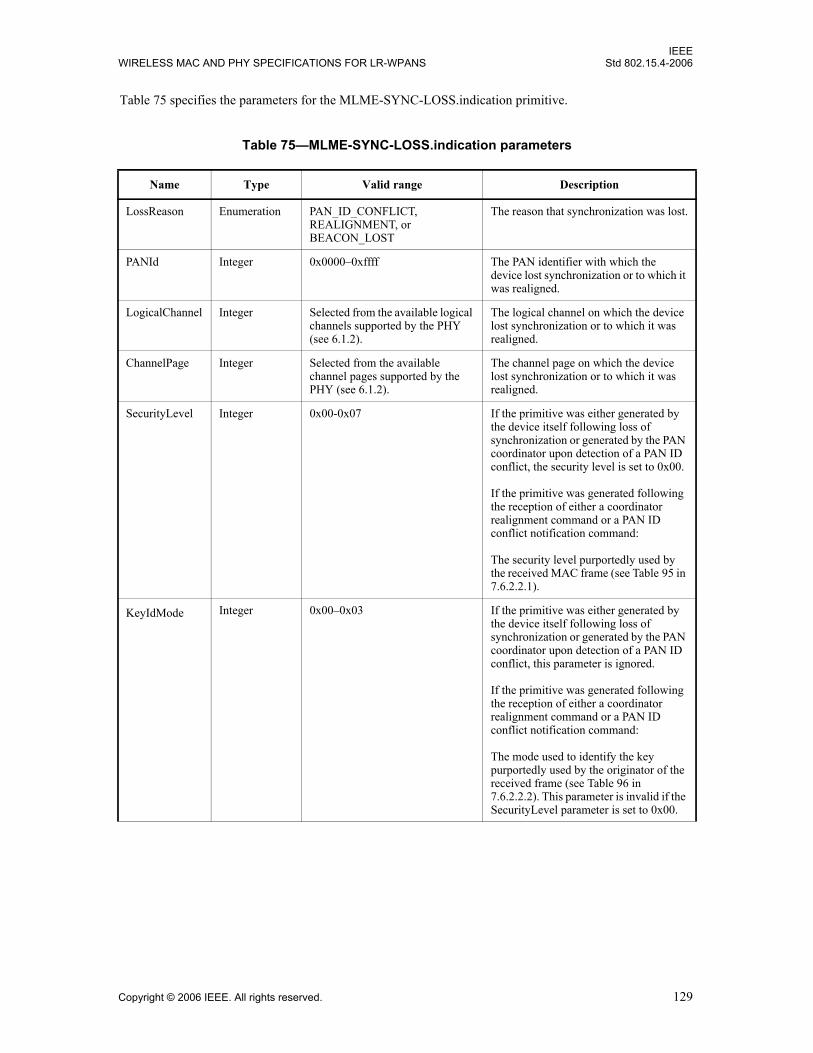
IEEEWIRELESS MAC AND PHY SPECIFICATIONS FOR LR-WPANS Std 802.15.4-2006
Table 75 specifies the parameters for the MLME-SYNC-LOSS.indication primitive.
Table 75—MLME-SYNC-LOSS.indication parameters
Name Type Valid range Description
LossReason Enumeration PAN_ID_CONFLICT, REALIGNMENT, or BEACON_LOST
The reason that synchronization was lost.
PANId Integer 0x0000–0xffff The PAN identifier with which the device lost synchronization or to which it was realigned.
LogicalChannel Integer Selected from the available logical channels supported by the PHY (see 6.1.2).
The logical channel on which the device lost synchronization or to which it was realigned.
ChannelPage Integer Selected from the available channel pages supported by the PHY (see 6.1.2).
The channel page on which the device lost synchronization or to which it was realigned.
SecurityLevel Integer 0x00-0x07 If the primitive was either generated by the device itself following loss of synchronization or generated by the PAN coordinator upon detection of a PAN ID conflict, the security level is set to 0x00.
If the primitive was generated following the reception of either a coordinator realignment command or a PAN ID conflict notification command:
The security level purportedly used by the received MAC frame (see Table 95 in 7.6.2.2.1).
KeyIdMode Integer 0x00–0x03 If the primitive was either generated by the device itself following loss of synchronization or generated by the PAN coordinator upon detection of a PAN ID conflict, this parameter is ignored.
If the primitive was generated following the reception of either a coordinator realignment command or a PAN ID conflict notification command:
The mode used to identify the key purportedly used by the originator of the received frame (see Table 96 in 7.6.2.2.2). This parameter is invalid if the SecurityLevel parameter is set to 0x00.
Copyright © 2006 IEEE. All rights reserved. 129

IEEEStd 802.15.4-2006 LOCAL AND METROPOLITAN AREA NETWORKS—PART 15.4:
7.1.15.2.2 When generated
The MLME-SYNC-LOSS.indication primitive is generated by the MLME of a device and issued to its nexthigher layer in the event of a loss of synchronization with the coordinator. It is also generated by the MLMEof the PAN coordinator and issued to its next higher layer in the event of a PAN ID conflict.
If a device that is associated through the PAN coordinator has detected a PAN identifier conflict andcommunicated it to the PAN coordinator, the MLME will issue this primitive with the LossReasonparameter set to PAN_ID_CONFLICT. Similarly, if the PAN coordinator receives a PAN ID conflictnotification command (see 7.3.5), the MLME will issue this primitive with the LossReason parameter set toPAN_ID_CONFLICT.
If a device has received the coordinator realignment command (see 7.3.8) from the coordinator throughwhich it is associated and the MLME was not carrying out an orphan scan, the MLME will issue thisprimitive with the LossReason parameter set to REALIGNMENT and the PANId, LogicalChannel,ChannelPage, and security-related parameters set as described in 7.5.2.3.3.
If a device has not heard the beacon for aMaxLostBeacons consecutive superframes following an MLME-SYNC.request primitive, either initially or during tracking, the MLME will issue this primitive with theLossReason parameter set to BEACON_LOST. The PANId, LogicalChannel and ChannelPage parameters
KeySource Set of 0, 4, or 8 octets
As specified by the KeyIdMode parameter
If the primitive was either generated by the device itself following loss of synchronization or generated by the PAN coordinator upon detection of a PAN ID conflict, this parameter is ignored.
If the primitive was generated following the reception of either a coordinator realignment command or a PAN ID conflict notification command:
The originator of the key purportedly used by the originator of the received frame (see 7.6.2.4.1). This parameter is invalid if the KeyIdMode parameter is invalid or set to 0x00.
KeyIndex Integer 0x01–0xff If the primitive was either generated by the device itself following loss of synchronization or generated by the PAN coordinator upon detection of a PAN ID conflict, this parameter is ignored.
If the primitive was generated following the reception of either a coordinator realignment command or a PAN ID conflict notification command:
The index of the key purportedly used by the originator of the received frame (see 7.6.2.4.2). This parameter is invalid if the KeyIdMode parameter is invalid or set to 0x00.
Table 75—MLME-SYNC-LOSS.indication parameters (continued)
Name Type Valid range Description
130 Copyright © 2006 IEEE. All rights reserved.
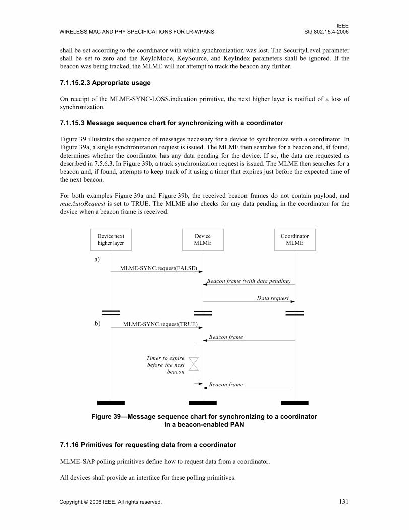
IEEEWIRELESS MAC AND PHY SPECIFICATIONS FOR LR-WPANS Std 802.15.4-2006
shall be set according to the coordinator with which synchronization was lost. The SecurityLevel parametershall be set to zero and the KeyIdMode, KeySource, and KeyIndex parameters shall be ignored. If thebeacon was being tracked, the MLME will not attempt to track the beacon any further.
7.1.15.2.3 Appropriate usage
On receipt of the MLME-SYNC-LOSS.indication primitive, the next higher layer is notified of a loss ofsynchronization.
7.1.15.3 Message sequence chart for synchronizing with a coordinator
Figure 39 illustrates the sequence of messages necessary for a device to synchronize with a coordinator. InFigure 39a, a single synchronization request is issued. The MLME then searches for a beacon and, if found,determines whether the coordinator has any data pending for the device. If so, the data are requested asdescribed in 7.5.6.3. In Figure 39b, a track synchronization request is issued. The MLME then searches for abeacon and, if found, attempts to keep track of it using a timer that expires just before the expected time ofthe next beacon.
For both examples Figure 39a and Figure 39b, the received beacon frames do not contain payload, andmacAutoRequest is set to TRUE. The MLME also checks for any data pending in the coordinator for thedevice when a beacon frame is received.
7.1.16 Primitives for requesting data from a coordinator
MLME-SAP polling primitives define how to request data from a coordinator.
All devices shall provide an interface for these polling primitives.
Figure 39—Message sequence chart for synchronizing to a coordinator in a beacon-enabled PAN
Device nexthigher layer
DeviceMLME
MLME-SYNC.request(FALSE)
Beacon frame (with data pending)
Data request
Timer to expirebefore the next
beacon
CoordinatorMLME
MLME-SYNC.request(TRUE)
Beacon frame
Beacon frame
a)
b)
Copyright © 2006 IEEE. All rights reserved. 131

IEEEStd 802.15.4-2006 LOCAL AND METROPOLITAN AREA NETWORKS—PART 15.4:
7.1.16.1 MLME-POLL.request
The MLME-POLL.request primitive prompts the device to request data from the coordinator.
7.1.16.1.1 Semantics of the service primitive
The semantics of the MLME-POLL.request primitive are as follows:
Table 76 specifies the parameter for the MLME-POLL.request primitive.
Table 76—MLME-POLL.request parameters
Name Type Valid range Description
CoordAddrMode Integer 0x02–0x03 The addressing mode of the coordinator to which the poll is intended. This parameter can take one of the following values:
2 = 16-bit short address,3 = 64-bit extended address.
CoordPANId Integer 0x0000–0xfffe The PAN identifier of the coordinator to which the poll is intended.
CoordAddress Device-Address
As specified by the CoordAddrMode parameter
The address of the coordinator to which the poll is intended.
SecurityLevel Integer 0x00–0x07 The security level to be used (see Table 95 in 7.6.2.2.1).
KeyIdMode Integer 0x00–0x03 The mode used to identify the key to be used (see Table 96 in 7.6.2.2.2). This parameter is ignored if the SecurityLevel parameter is set to 0x00.
KeySource Set of 0, 4, or 8 octets
As specified by the KeyIdMode parameter
The originator of the key to be used (see 7.6.2.4.1). This parameter is ignored if the KeyIdMode parameter is ignored or set to 0x00.
KeyIndex Integer 0x01–0xff The index of the key to be used (see 7.6.2.4.2). This parameter is ignored if the KeyIdMode parameter is ignored or set to 0x00.
MLME-POLL.request (CoordAddrMode,CoordPANId,CoordAddress,SecurityLevel,KeyIdMode,KeySource,KeyIndex)
132 Copyright © 2006 IEEE. All rights reserved.

IEEEWIRELESS MAC AND PHY SPECIFICATIONS FOR LR-WPANS Std 802.15.4-2006
7.1.16.1.2 Appropriate usage
The MLME-POLL.request primitive is generated by the next higher layer and issued to its MLME whendata are to be requested from a coordinator.
7.1.16.1.3 Effect on receipt
On receipt of the MLME-POLL.request primitive, the MLME generates and sends a data request command(see 7.3.4). If the poll is directed to the PAN coordinator, the data request command may be generatedwithout any destination address information present. Otherwise, the data request command is alwaysgenerated with the destination address information in the CoordPANId and CoordAddress parameters.
If the SecurityLevel parameter is set to a valid value other than 0x00, indicating that security is required forthis frame, the MLME will set the Security Enabled subfield of the Frame Control field to one. The MACsublayer will perform outgoing processing on the frame based on the CoordAddress, SecurityLevel,KeyIdMode, KeySource, and KeyIndex parameters, as described in 7.5.8.2.1. If any error occurs duringoutgoing frame processing, the MLME will discard the frame and issue the MLME-POLL.confirm primitivewith the error status returned by outgoing frame processing.
If the data request command cannot be sent due to a CSMA-CA algorithm failure, the MLME will issue theMLME-POLL.confirm primitive with a status of CHANNEL_ACCESS_FAILURE.
If the MLME successfully transmits a data request command, the MLME will expect an acknowledgment inreturn. If an acknowledgment is not received, the MLME will issue the MLME-POLL.confirm primitivewith a status of NO_ACK (see 7.5.6.4).
If an acknowledgment is received, the MLME will request that the PHY enable its receiver if the FramePending subfield of the acknowledgment frame is set to one. If the Frame Pending subfield of theacknowledgment frame is set to zero, the MLME will issue the MLME-POLL.confirm primitive with astatus of NO_DATA.
If a frame is received from the coordinator with a zero length payload or if the frame is a MAC commandframe, the MLME will issue the MLME-POLL.confirm primitive with a status of NO_DATA. If a frame isreceived from the coordinator with nonzero length payload, the MLME will issue the MLME-POLL.confirm primitive with a status of SUCCESS. In this case, the actual data are indicated to the nexthigher layer using the MCPS-DATA.indication primitive (see 7.1.1.3).
If a frame is not received within macMaxFrameTotalWaitTime CAP symbols in a beacon-enabled PAN, orsymbols in a nonbeacon-enabled PAN, even though the acknowledgment to the data request command hasits Frame Pending subfield set to one, the MLME will issue the MLME-POLL.confirm primitive with astatus of NO_DATA.
If any parameter in the MLME-POLL.request primitive is not supported or is out of range, the MLME willissue the MLME-POLL.confirm primitive with a status of INVALID_PARAMETER.
7.1.16.2 MLME-POLL.confirm
The MLME-POLL.confirm primitive reports the results of a request to poll the coordinator for data.
7.1.16.2.1 Semantics of the service primitive
The semantics of the MLME-POLL.confirm primitive are as follows:
Copyright © 2006 IEEE. All rights reserved. 133
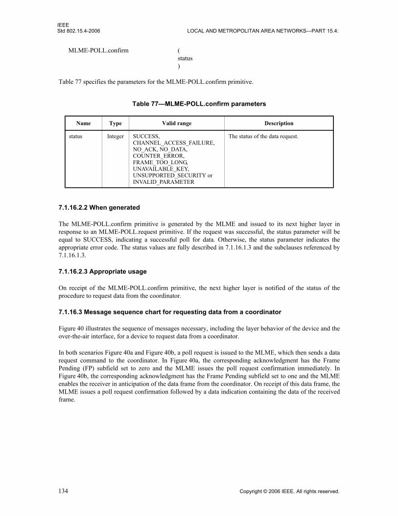
IEEEStd 802.15.4-2006 LOCAL AND METROPOLITAN AREA NETWORKS—PART 15.4:
Table 77 specifies the parameters for the MLME-POLL.confirm primitive.
7.1.16.2.2 When generated
The MLME-POLL.confirm primitive is generated by the MLME and issued to its next higher layer inresponse to an MLME-POLL.request primitive. If the request was successful, the status parameter will beequal to SUCCESS, indicating a successful poll for data. Otherwise, the status parameter indicates theappropriate error code. The status values are fully described in 7.1.16.1.3 and the subclauses referenced by7.1.16.1.3.
7.1.16.2.3 Appropriate usage
On receipt of the MLME-POLL.confirm primitive, the next higher layer is notified of the status of theprocedure to request data from the coordinator.
7.1.16.3 Message sequence chart for requesting data from a coordinator
Figure 40 illustrates the sequence of messages necessary, including the layer behavior of the device and theover-the-air interface, for a device to request data from a coordinator.
In both scenarios Figure 40a and Figure 40b, a poll request is issued to the MLME, which then sends a datarequest command to the coordinator. In Figure 40a, the corresponding acknowledgment has the FramePending (FP) subfield set to zero and the MLME issues the poll request confirmation immediately. InFigure 40b, the corresponding acknowledgment has the Frame Pending subfield set to one and the MLMEenables the receiver in anticipation of the data frame from the coordinator. On receipt of this data frame, theMLME issues a poll request confirmation followed by a data indication containing the data of the receivedframe.
Table 77—MLME-POLL.confirm parameters
Name Type Valid range Description
status Integer SUCCESS, CHANNEL_ACCESS_FAILURE, NO_ACK, NO_DATA, COUNTER_ERROR, FRAME_TOO_LONG, UNAVAILABLE_KEY, UNSUPPORTED_SECURITY or INVALID_PARAMETER
The status of the data request.
MLME-POLL.confirm (status)
134 Copyright © 2006 IEEE. All rights reserved.

IEEEWIRELESS MAC AND PHY SPECIFICATIONS FOR LR-WPANS Std 802.15.4-2006
7.1.17 MAC enumeration description
This subclause explains the meaning of the enumerations used in the primitives defined in the MACsublayer specification. Table 78 shows a description of the MAC enumeration values.
Table 78—MAC enumerations description
Enumeration Value Description
SUCCESS 0x00 The requested operation was completed successfully. For a transmission request, this value indicates a successful transmission.
— 0x01–0xda Reserved for MAC command status and reason code values.
— 0x80–0xda, 0xfe–0xff
Reserved.
BEACON_LOSS 0xe0 The beacon was lost following a synchronization request.
CHANNEL_ACCESS_FAILURE 0xe1 A transmission could not take place due to activity on the channel, i.e., the CSMA-CA mechanism has failed.
COUNTER_ERROR 0xdb The frame counter purportedly applied by the originator of the received frame is invalid.
DENIED 0xe2 The GTS request has been denied by the PAN coordinator.
DISABLE_TRX_FAILURE 0xe3 The attempt to disable the transceiver has failed.
FRAME_TOO_LONG 0xe5 Either a frame resulting from processing has a length that is greater than aMaxPHYPacketSize or a requested transaction is too large to fit in the CAP or GTS.
Figure 40—Message sequence chart for requesting data from the coordinator
Copyright © 2006 IEEE. All rights reserved. 135

IEEEStd 802.15.4-2006 LOCAL AND METROPOLITAN AREA NETWORKS—PART 15.4:
IMPROPER_KEY_TYPE 0xdc The key purportedly applied by the originator of the received frame is not allowed to be used with that frame type according to the key usage policy of the recipient.
IMPROPER_SECURITY_LEVEL 0xdd The security level purportedly applied by the originator of the received frame does not meet the minimum security level required/expected by the recipient for that frame type.
INVALID_ADDRESS 0xf5 A request to send data was unsuccessful because neither the source address parameters nor the destination address parameters were present.
INVALID_GTS 0xe6 The requested GTS transmission failed because the specified GTS either did not have a transmit GTS direction or was not defined.
INVALID_HANDLE 0xe7 A request to purge an MSDU from the transaction queue was made using an MSDU handle that was not found in the transaction table.
INVALID_INDEX 0xf9 An attempt to write to a MAC PIB attribute that is in a table failed because the specified table index was out of range.
INVALID_PARAMETER 0xe8 A parameter in the primitive is either not supported or is out of the valid range.
LIMIT_REACHED 0xfa A scan operation terminated prematurely because the number of PAN descriptors stored reached an implementation-specified maximum.
NO_ACK 0xe9 No acknowledgment was received after macMaxFrameRetries.
NO_BEACON 0xea A scan operation failed to find any network beacons.
NO_DATA 0xeb No response data were available following a request.
NO_SHORT_ADDRESS 0xec The operation failed because a 16-bit short address was not allocated.
ON_TIME_TOO_LONG 0xf6 A receiver enable request was unsuccessful because it specified a number of symbols that was longer than the beacon interval.
OUT_OF_CAP 0xed A receiver enable request was unsuccessful because it could not be completed within the CAP.
The enumeration description is not used in this standard, and it is included only to meet the backwards compatibility requirements for IEEE Std 802.15.4-2003.
PAN_ID_CONFLICT 0xee A PAN identifier conflict has been detected and communicated to the PAN coordinator.
PAST_TIME 0xf7 A receiver enable request was unsuccessful because it could not be completed within the current superframe and was not permitted to be deferred until the next superframe.
READ_ONLY 0xfb A SET/GET request was issued with the identifier of an attribute that is read only.
REALIGNMENT 0xef A coordinator realignment command has been received.
Table 78—MAC enumerations description (continued)
Enumeration Value Description
136 Copyright © 2006 IEEE. All rights reserved.
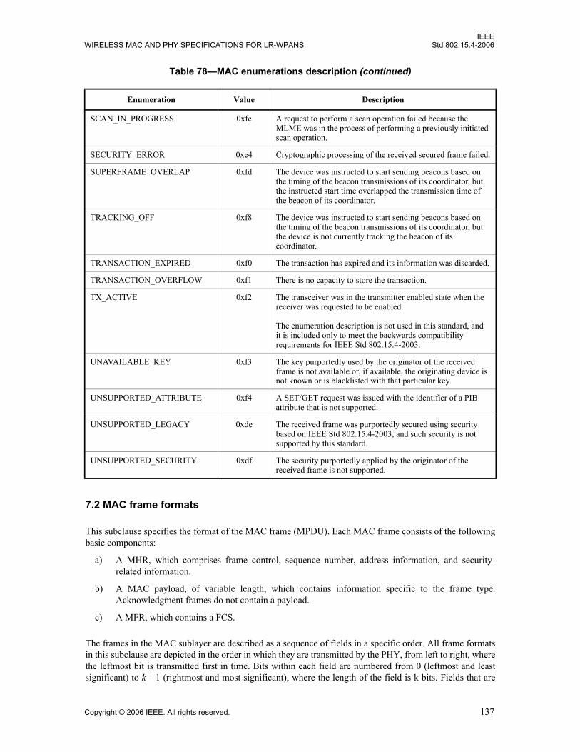
IEEEWIRELESS MAC AND PHY SPECIFICATIONS FOR LR-WPANS Std 802.15.4-2006
7.2 MAC frame formats
This subclause specifies the format of the MAC frame (MPDU). Each MAC frame consists of the followingbasic components:
a) A MHR, which comprises frame control, sequence number, address information, and security-related information.
b) A MAC payload, of variable length, which contains information specific to the frame type.Acknowledgment frames do not contain a payload.
c) A MFR, which contains a FCS.
The frames in the MAC sublayer are described as a sequence of fields in a specific order. All frame formatsin this subclause are depicted in the order in which they are transmitted by the PHY, from left to right, wherethe leftmost bit is transmitted first in time. Bits within each field are numbered from 0 (leftmost and leastsignificant) to k – 1 (rightmost and most significant), where the length of the field is k bits. Fields that are
SCAN_IN_PROGRESS 0xfc A request to perform a scan operation failed because the MLME was in the process of performing a previously initiated scan operation.
SECURITY_ERROR 0xe4 Cryptographic processing of the received secured frame failed.
SUPERFRAME_OVERLAP 0xfd The device was instructed to start sending beacons based on the timing of the beacon transmissions of its coordinator, but the instructed start time overlapped the transmission time of the beacon of its coordinator.
TRACKING_OFF 0xf8 The device was instructed to start sending beacons based on the timing of the beacon transmissions of its coordinator, but the device is not currently tracking the beacon of its coordinator.
TRANSACTION_EXPIRED 0xf0 The transaction has expired and its information was discarded.
TRANSACTION_OVERFLOW 0xf1 There is no capacity to store the transaction.
TX_ACTIVE 0xf2 The transceiver was in the transmitter enabled state when the receiver was requested to be enabled.
The enumeration description is not used in this standard, and it is included only to meet the backwards compatibility requirements for IEEE Std 802.15.4-2003.
UNAVAILABLE_KEY 0xf3 The key purportedly used by the originator of the received frame is not available or, if available, the originating device is not known or is blacklisted with that particular key.
UNSUPPORTED_ATTRIBUTE 0xf4 A SET/GET request was issued with the identifier of a PIB attribute that is not supported.
UNSUPPORTED_LEGACY 0xde The received frame was purportedly secured using security based on IEEE Std 802.15.4-2003, and such security is not supported by this standard.
UNSUPPORTED_SECURITY 0xdf The security purportedly applied by the originator of the received frame is not supported.
Table 78—MAC enumerations description (continued)
Enumeration Value Description
Copyright © 2006 IEEE. All rights reserved. 137
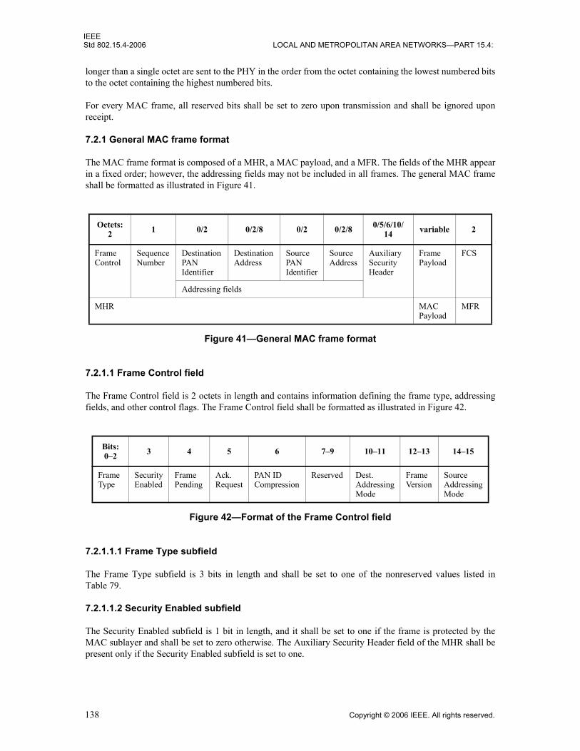
IEEEStd 802.15.4-2006 LOCAL AND METROPOLITAN AREA NETWORKS—PART 15.4:
longer than a single octet are sent to the PHY in the order from the octet containing the lowest numbered bitsto the octet containing the highest numbered bits.
For every MAC frame, all reserved bits shall be set to zero upon transmission and shall be ignored uponreceipt.
7.2.1 General MAC frame format
The MAC frame format is composed of a MHR, a MAC payload, and a MFR. The fields of the MHR appearin a fixed order; however, the addressing fields may not be included in all frames. The general MAC frameshall be formatted as illustrated in Figure 41.
7.2.1.1 Frame Control field
The Frame Control field is 2 octets in length and contains information defining the frame type, addressingfields, and other control flags. The Frame Control field shall be formatted as illustrated in Figure 42.
7.2.1.1.1 Frame Type subfield
The Frame Type subfield is 3 bits in length and shall be set to one of the nonreserved values listed inTable 79.
7.2.1.1.2 Security Enabled subfield
The Security Enabled subfield is 1 bit in length, and it shall be set to one if the frame is protected by theMAC sublayer and shall be set to zero otherwise. The Auxiliary Security Header field of the MHR shall bepresent only if the Security Enabled subfield is set to one.
Octets: 2 1 0/2 0/2/8 0/2 0/2/8 0/5/6/10/
14 variable 2
FrameControl
SequenceNumber
DestinationPANIdentifier
DestinationAddress
SourcePANIdentifier
SourceAddress
AuxiliarySecurityHeader
FramePayload
FCS
Addressing fields
MHR MACPayload
MFR
Figure 41—General MAC frame format
Bits: 0–2 3 4 5 6 7–9 10–11 12–13 14–15
FrameType
SecurityEnabled
FramePending
Ack.Request
PAN IDCompression
Reserved Dest.AddressingMode
FrameVersion
SourceAddressingMode
Figure 42—Format of the Frame Control field
138 Copyright © 2006 IEEE. All rights reserved.

IEEEWIRELESS MAC AND PHY SPECIFICATIONS FOR LR-WPANS Std 802.15.4-2006
7.2.1.1.3 Frame Pending subfield
The Frame Pending subfield is 1 bit in length and shall be set to one if the device sending the frame has moredata for the recipient. This subfield shall be set to zero otherwise (see 7.5.6.3).
The Frame Pending subfield shall be used only in beacon frames or frames transmitted either during theCAP by devices operating on a beacon-enabled PAN or at any time by devices operating on a nonbeacon-enabled PAN.
At all other times, it shall be set to zero on transmission and ignored on reception.
7.2.1.1.4 Acknowledgment Request subfield
The Acknowledgment Request subfield is 1 bit in length and specifies whether an acknowledgment isrequired from the recipient device on receipt of a data or MAC command frame. If this subfield is set to one,the recipient device shall send an acknowledgment frame only if, upon reception, the frame passes the thirdlevel of filtering (see 7.5.6.2). If this subfield is set to zero, the recipient device shall not send anacknowledgment frame.
7.2.1.1.5 PAN ID Compression subfield
The PAN ID Compression subfield is 1 bit in length and specifies whether the MAC frame is to be sentcontaining only one of the PAN identifier fields when both source and destination addresses are present. Ifthis subfield is set to one and both the source and destination addresses are present, the frame shall containonly the Destination PAN Identifier field, and the Source PAN Identifier field shall be assumed equal to thatof the destination. If this subfield is set to zero and both the source and destination addresses are present, theframe shall contain both the Source PAN Identifier and Destination PAN Identifier fields. If only one of theaddresses is present, this subfield shall be set to zero, and the frame shall contain the PAN identifier fieldcorresponding to the address. If neither address is present, this subfield shall be set to zero, and the frameshall not contain either PAN identifier field.
7.2.1.1.6 Destination Addressing Mode subfield
The Destination Addressing Mode subfield is 2 bits in length and shall be set to one of the nonreservedvalues listed in Table 80.
If this subfield is equal to zero and the Frame Type subfield does not specify that this frame is anacknowledgment or beacon frame, the Source Addressing Mode subfield shall be nonzero, implying that theframe is directed to the PAN coordinator with the PAN identifier as specified in the Source PAN Identifierfield.
Table 79—Values of the Frame Type subfield
Frame type valueb2 b1 b0
Description
000 Beacon
001 Data
010 Acknowledgment
011 MAC command
100–111 Reserved
Copyright © 2006 IEEE. All rights reserved. 139

IEEEStd 802.15.4-2006 LOCAL AND METROPOLITAN AREA NETWORKS—PART 15.4:
7.2.1.1.7 Frame Version subfield
The Frame Version subfield is 2 bits in length and specifies the version number corresponding to the frame.
This subfield shall be set to 0x00 to indicate a frame compatible with IEEE Std 802.15.4-2003 and 0x01 toindicate an IEEE 802.15.4 frame. All other subfield values shall be reserved for future use. See 7.2.3 fordetails on frame compatibility.
7.2.1.1.8 Source Addressing Mode subfield
The Source Addressing Mode subfield is 2 bits in length and shall be set to one of the nonreserved valueslisted in Table 80.
If this subfield is equal to zero and the Frame Type subfield does not specify that this frame is anacknowledgment frame, the Destination Addressing Mode subfield shall be nonzero, implying that theframe has originated from the PAN coordinator with the PAN identifier as specified in the Destination PANIdentifier field.
7.2.1.2 Sequence Number field
The Sequence Number field is 1 octet in length and specifies the sequence identifier for the frame.
For a beacon frame, the Sequence Number field shall specify a BSN. For a data, acknowledgment, or MACcommand frame, the Sequence Number field shall specify a DSN that is used to match an acknowledgmentframe to the data or MAC command frame.
7.2.1.3 Destination PAN Identifier field
The Destination PAN Identifier field, when present, is 2 octets in length and specifies the unique PANidentifier of the intended recipient of the frame. A value of 0xffff in this field shall represent the broadcastPAN identifier, which shall be accepted as a valid PAN identifier by all devices currently listening to thechannel.
This field shall be included in the MAC frame only if the Destination Addressing Mode subfield of theFrame Control field is nonzero.
7.2.1.4 Destination Address field
The Destination Address field, when present, is either 2 octets or 8 octets in length, according to the valuespecified in the Destination Addressing Mode subfield of the Frame Control field (see 7.2.1.1.6), and
Table 80—Possible values of the Destination Addressing Mode and Source Addressing Mode subfields
Addressing mode valueb1 b0
Description
00 PAN identifier and address fields are not present.
01 Reserved.
10 Address field contains a 16-bit short address.
11 Address field contains a 64-bit extended address.
140 Copyright © 2006 IEEE. All rights reserved.

IEEEWIRELESS MAC AND PHY SPECIFICATIONS FOR LR-WPANS Std 802.15.4-2006
specifies the address of the intended recipient of the frame. A 16-bit value of 0xffff in this field shallrepresent the broadcast short address, which shall be accepted as a valid 16-bit short address by all devicescurrently listening to the channel.
This field shall be included in the MAC frame only if the Destination Addressing Mode subfield of theFrame Control field is nonzero.
7.2.1.5 Source PAN Identifier field
The Source PAN Identifier field, when present, is 2 octets in length and specifies the unique PAN identifierof the originator of the frame. This field shall be included in the MAC frame only if the Source AddressingMode and PAN ID Compression subfields of the Frame Control field are nonzero and equal to zero,respectively.
The PAN identifier of a device is initially determined during association on a PAN, but may changefollowing a PAN identifier conflict resolution (see 7.5.2.2).
7.2.1.6 Source Address field
The Source Address field, when present, is either 2 octets or 8 octets in length, according to the valuespecified in the Source Addressing Mode subfield of the Frame Control field (see 7.2.1.1.8), and specifiesthe address of the originator of the frame. This field shall be included in the MAC frame only if the SourceAddressing Mode subfield of the Frame Control field is nonzero.
7.2.1.7 Auxiliary Security Header field
The Auxiliary Security Header field has a variable length and specifies information required for securityprocessing, including how the frame is actually protected (security level) and which keying material fromthe MAC security PIB is used (see 7.6.1). This field shall be present only if the Security Enabled subfield isset to one. For details on formatting, see 7.6.2.
7.2.1.8 Frame Payload field
The Frame Payload field has a variable length and contains information specific to individual frame types. Ifthe Security Enabled subfield is set to one in the Frame Control field, the frame payload is protected asdefined by the security suite selected for that frame.
7.2.1.9 FCS field
The FCS field is 2 octets in length and contains a 16-bit ITU-T CRC. The FCS is calculated over the MHRand MAC payload parts of the frame.
The FCS shall be calculated using the following standard generator polynomial of degree 16:
(12)
The FCS shall be calculated for transmission using the following algorithm: — Let be the polynomial representing the sequence of
bits for which the checksum is to be computed.— Multiply M(x) by x16, giving the polynomial .— Divide modulo 2 by the generator polynomial, G16(x), to obtain the remainder polyno-
mial, .
G16 x( ) x16 x12 x5 1+ + +=
M x( ) b0xk 1– b1xk 2– … bk 2– x bk 1–+ + + +=
x16 M x( )×x16 M x( )×
R x( ) r0x15 r1x14 … r14x r15+ + + +=
Copyright © 2006 IEEE. All rights reserved. 141

IEEEStd 802.15.4-2006 LOCAL AND METROPOLITAN AREA NETWORKS—PART 15.4:
— The FCS field is given by the coefficients of the remainder polynomial, R(x).
Here, binary polynomials are represented as bit strings, in highest polynomial degree first order.
As an example, consider an acknowledgment frame with no payload and the following 3 byte MHR:
The FCS for this case would be the following:
A typical implementation is depicted in Figure 43.
7.2.2 Format of individual frame types
Four frame types are defined: beacon, data, acknowledgment, and MAC command. These frame types arediscussed in 7.2.2.1 through 7.2.2.4.
7.2.2.1 Beacon frame format
The beacon frame shall be formatted as illustrated in Figure 44.
The GTS fields shall be formatted as illustrated in Figure 45, and the pending address fields shall beformatted as illustrated in Figure 46.
The order of the fields of the beacon frame shall conform to the order of the general MAC frame asillustrated in Figure 41.
0100 0000 0000 0000 0101 0110 b0.................................................b23
[leftmost bit (b0) transmitted first in time]
0010 0111 1001 1110 r0..............................r15
[leftmost bit (r0) transmitted first in time]
Data FieldInput
r0 r1
CRC-16 Generator Polynomial: G(x) = x16 + x12 + x5 + 1
r2 r3 r5 r6 r7 r8 r9 r10 r11 r12 r13 r14 r15r4
1. Initialize the remainder register (r0 through r15) to zero.2. Shift MHR and payload into the divider in the order of
transmission (LSB first).3. After the last bit of the data field is shifted into the divider,
the remainder register contains the FCS.4. The FCS is appended to the data field so that r0 is transmitted first.
(LSB first)
Figure 43—Typical FCS implementation
142 Copyright © 2006 IEEE. All rights reserved.

IEEEWIRELESS MAC AND PHY SPECIFICATIONS FOR LR-WPANS Std 802.15.4-2006
7.2.2.1.1 Beacon frame MHR fields
The MHR for a beacon frame shall contain the Frame Control field, the Sequence Number field, the SourcePAN Identifier field, and the Source Address field.
In the Frame Control field, the Frame Type subfield shall contain the value that indicates a beacon frame, asshown in Table 79, and the Source Addressing Mode subfield shall be set as appropriate for the address ofthe coordinator transmitting the beacon frame. If protection is used for the beacon, the Security Enabledsubfield shall be set to one. The Frame Version subfield shall be set to one only if the Security Enabledsubfield is set to one. If a broadcast data or command frame is pending, the Frame Pending subfield shall beset to one. All other subfields shall be set to zero and ignored on reception.
The Sequence Number field shall contain the current value of macBSN.
The addressing fields shall comprise only the source address fields. The Source PAN Identifier and SourceAddress fields shall contain the PAN identifier and address, respectively, of the device transmitting thebeacon.
The Auxiliary Security Header field, if present, shall contain the information required for securityprocessing of the beacon frame, as specified in 7.2.1.7.
7.2.2.1.2 Superframe Specification field
The Superframe Specification field is 16 bits in length and shall be formatted as illustrated in Figure 47.
Octets: 2 1 4/10 0/5/6/10/14 2 variable variable variable 2
FrameControl
SequenceNumber
Addressingfields
AuxiliarySecurity Header
SuperframeSpecification
GTSfields (Figure 45)
Pendingaddressfields (Figure 46)
BeaconPayload
FCS
MHR MAC Payload MFR
Figure 44—Beacon frame format
Octets: 1 0/1 variable
GTS Specification GTS Directions GTS List
Figure 45—Format of the GTS information fields
Octets: 1 variable
Pending Address Specification Address List
Figure 46—Format of the pending address information fields
Copyright © 2006 IEEE. All rights reserved. 143

IEEEStd 802.15.4-2006 LOCAL AND METROPOLITAN AREA NETWORKS—PART 15.4:
The Beacon Order subfield is 4 bits in length and shall specify the transmission interval of the beacon. See7.5.1.1 for an explanation of the relationship between the beacon order and the beacon interval.
The Superframe Order subfield is 4 bits in length and shall specify the length of time during which thesuperframe is active (i.e., receiver enabled), including the beacon frame transmission time. See 7.5.1.1 for anexplanation of the relationship between the superframe order and the superframe duration.
The Final CAP Slot subfield is 4 bits in length and specifies the final superframe slot utilized by the CAP.The duration of the CAP, as implied by this subfield, shall be greater than or equal to the value specified byaMinCAPLength. However, an exception is allowed for the accommodation of the temporary increase in thebeacon frame length needed to perform GTS maintenance (see 7.2.2.1.3).
The Battery Life Extension (BLE) subfield is 1 bit in length and shall be set to one if frames transmitted tothe beaconing device during its CAP are required to start in or before macBattLifeExtPeriods full backoffperiods after the IFS period following the beacon. Otherwise, the BLE subfield shall be set to zero.
The PAN Coordinator subfield is 1 bit in length and shall be set to one if the beacon frame is beingtransmitted by the PAN coordinator. Otherwise, the PAN Coordinator subfield shall be set to zero.
The Association Permit subfield is 1 bit in length and shall be set to one if macAssociationPermit is set toTRUE (i.e., the coordinator is accepting association to the PAN). The association permit bit shall be set tozero if the coordinator is currently not accepting association requests on its network.
7.2.2.1.3 GTS Specification field
The GTS Specification field is 8 bits in length and shall be formatted as illustrated in Figure 48.
The GTS Descriptor Count subfield is 3 bits in length and specifies the number of 3-octet GTS descriptorscontained in the GTS List field of the beacon frame. If the value of this subfield is greater than zero, the sizeof the CAP shall be allowed to dip below aMinCAPLength to accommodate the temporary increase in thebeacon frame length caused by the inclusion of the subfield. If the value of this subfield is zero, the GTSDirections field and GTS List field of the beacon frame are not present.
The GTS Permit subfield is 1 bit in length and shall be set to one if macGTSPermit is equal to TRUE (i.e.,the PAN coordinator is accepting GTS requests). Otherwise, the GTS Permit field shall be set to zero.
Bits: 0–3 4-7 8-11 12 13 14 15
BeaconOrder
SuperframeOrder
FinalCAP Slot
Battery LifeExtension (BLE)
Reserved PANCoordinator
AssociationPermit
Figure 47—Format of the Superframe Specification field
Bits: 0-2 3-6 7
GTS Descriptor Count Reserved GTS Permit
Figure 48—Format of the GTS Specification field
144 Copyright © 2006 IEEE. All rights reserved.

IEEEWIRELESS MAC AND PHY SPECIFICATIONS FOR LR-WPANS Std 802.15.4-2006
7.2.2.1.4 GTS Directions field
The GTS Directions field is 8 bits in length and shall be formatted as illustrated in Figure 49.
The GTS Directions Mask subfield is 7 bits in length and contains a mask identifying the directions of theGTSs in the superframe. The lowest bit in the mask corresponds to the direction of the first GTS containedin the GTS List field of the beacon frame, with the remainder appearing in the order that they appear in thelist. Each bit shall be set to one if the GTS is a receive-only GTS or to zero if the GTS is a transmit-onlyGTS. GTS direction is defined relative to the direction of the data frame transmission by the device.
7.2.2.1.5 GTS List field
The size of the GTS List field is defined by the values specified in the GTS Specification field of the beaconframe and contains the list of GTS descriptors that represents the GTSs that are being maintained. Themaximum number of GTS descriptors shall be limited to seven.
Each GTS descriptor is 24 bits in length and shall be formatted as illustrated in Figure 50.
The Device Short Address subfield is 16 bits in length and shall contain the short address of the device forwhich the GTS descriptor is intended.
The GTS Starting Slot subfield is 4 bits in length and contains the superframe slot at which the GTS is tobegin.
The GTS Length subfield is 4 bits in length and contains the number of contiguous superframe slots overwhich the GTS is active.
7.2.2.1.6 Pending Address Specification field
The Pending Address Specification field shall be formatted as illustrated in Figure 51.
The Number of Short Addresses Pending subfield is 3 bits in length and indicates the number of 16-bit shortaddresses contained in the Address List field of the beacon frame.
The Number of Extended Addresses Pending subfield is 3 bits in length and indicates the number of 64-bitextended addresses contained in the Address List field of the beacon frame.
Bits: 0-6 7
GTS Directions Mask Reserved
Figure 49—Format of the GTS Directions field
Bits: 0-15 16-19 20-23
Device Short Address GTS Starting Slot GTS Length
Figure 50—Format of the GTS descriptor
Copyright © 2006 IEEE. All rights reserved. 145

IEEEStd 802.15.4-2006 LOCAL AND METROPOLITAN AREA NETWORKS—PART 15.4:
7.2.2.1.7 Address List field
The size of the Address List field is determined by the values specified in the Pending Address Specificationfield of the beacon frame and contains the list of addresses of the devices that currently have messagespending with the coordinator. The address list shall not contain the broadcast short address 0xffff.
The maximum number of addresses pending shall be limited to seven and may comprise both short andextended addresses. All pending short addresses shall appear first in the list followed by any extendedaddresses. If the coordinator is able to store more than seven transactions, it shall indicate them in its beaconon a first-come-first-served basis, ensuring that the beacon frame contains at most seven addresses.
7.2.2.1.8 Beacon Payload field
The Beacon Payload field is an optional sequence of up to aMaxBeaconPayloadLength octets specified to betransmitted in the beacon frame by the next higher layer. The set of octets contained in macBeaconPayloadshall be copied into this field.
7.2.2.2 Data frame format
The data frame shall be formatted as illustrated in Figure 52.
The order of the fields of the data frame shall conform to the order of the general MAC frame as illustratedin Figure 41.
7.2.2.2.1 Data frame MHR fields
The MHR for a data frame shall contain the Frame Control field, the Sequence Number field, the destinationPAN identifier/address fields, and/or the source PAN identifier/address fields.
In the Frame Control field, the Frame Type subfield shall contain the value that indicates a data frame, asshown in Table 79. If protection is used for the data, the Security Enabled subfield shall be set to one. TheFrame Version subfield shall be set to one if either the Security Enabled subfield is set to one or the MACPayload field is greater than aMaxMACSafePayloadSize. All other subfields shall be set appropriatelyaccording to the intended use of the data frame. All reserved subfields shall be set to zero and ignored onreception.
Bits: 0-2 3 4-6 7
Number of ShortAddresses Pending
Reserved Number of ExtendedAddresses Pending
Reserved
Figure 51—Format of the Pending Address Specification field
Octets: 2 1 (see 7.2.2.2.1) 0/5/6/10/14 variable 2
Frame Control SequenceNumber
Addressingfields
Auxiliary Security Header
Data Payload FCS
MHR MAC Payload MFR
Figure 52—Data frame format
146 Copyright © 2006 IEEE. All rights reserved.
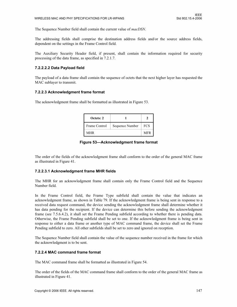
IEEEWIRELESS MAC AND PHY SPECIFICATIONS FOR LR-WPANS Std 802.15.4-2006
The Sequence Number field shall contain the current value of macDSN.
The addressing fields shall comprise the destination address fields and/or the source address fields,dependent on the settings in the Frame Control field.
The Auxiliary Security Header field, if present, shall contain the information required for securityprocessing of the data frame, as specified in 7.2.1.7.
7.2.2.2.2 Data Payload field
The payload of a data frame shall contain the sequence of octets that the next higher layer has requested theMAC sublayer to transmit.
7.2.2.3 Acknowledgment frame format
The acknowledgment frame shall be formatted as illustrated in Figure 53.
The order of the fields of the acknowledgment frame shall conform to the order of the general MAC frameas illustrated in Figure 41.
7.2.2.3.1 Acknowledgment frame MHR fields
The MHR for an acknowledgment frame shall contain only the Frame Control field and the SequenceNumber field.
In the Frame Control field, the Frame Type subfield shall contain the value that indicates anacknowledgment frame, as shown in Table 79. If the acknowledgment frame is being sent in response to areceived data request command, the device sending the acknowledgment frame shall determine whether ithas data pending for the recipient. If the device can determine this before sending the acknowledgmentframe (see 7.5.6.4.2), it shall set the Frame Pending subfield according to whether there is pending data.Otherwise, the Frame Pending subfield shall be set to one. If the acknowledgment frame is being sent inresponse to either a data frame or another type of MAC command frame, the device shall set the FramePending subfield to zero. All other subfields shall be set to zero and ignored on reception.
The Sequence Number field shall contain the value of the sequence number received in the frame for whichthe acknowledgment is to be sent.
7.2.2.4 MAC command frame format
The MAC command frame shall be formatted as illustrated in Figure 54.
The order of the fields of the MAC command frame shall conform to the order of the general MAC frame asillustrated in Figure 41.
Octets: 2 1 2
Frame Control Sequence Number FCS
MHR MFR
Figure 53—Acknowledgment frame format
Copyright © 2006 IEEE. All rights reserved. 147
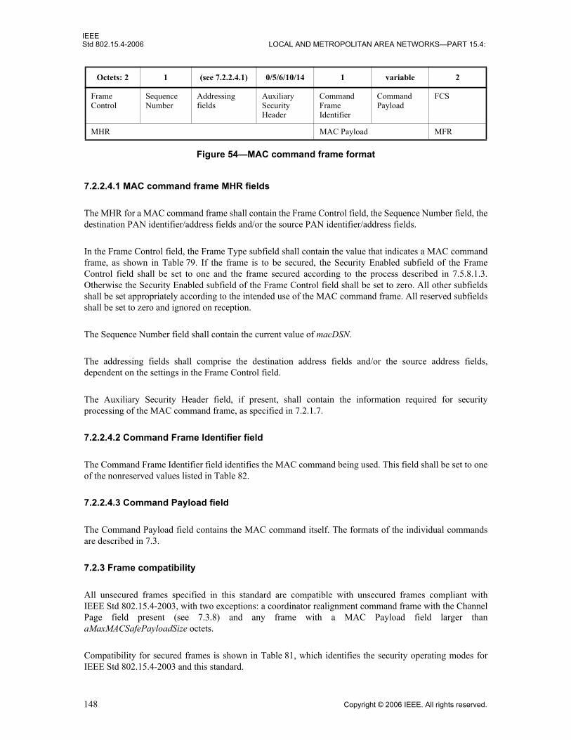
IEEEStd 802.15.4-2006 LOCAL AND METROPOLITAN AREA NETWORKS—PART 15.4:
7.2.2.4.1 MAC command frame MHR fields
The MHR for a MAC command frame shall contain the Frame Control field, the Sequence Number field, thedestination PAN identifier/address fields and/or the source PAN identifier/address fields.
In the Frame Control field, the Frame Type subfield shall contain the value that indicates a MAC commandframe, as shown in Table 79. If the frame is to be secured, the Security Enabled subfield of the FrameControl field shall be set to one and the frame secured according to the process described in 7.5.8.1.3.Otherwise the Security Enabled subfield of the Frame Control field shall be set to zero. All other subfieldsshall be set appropriately according to the intended use of the MAC command frame. All reserved subfieldsshall be set to zero and ignored on reception.
The Sequence Number field shall contain the current value of macDSN.
The addressing fields shall comprise the destination address fields and/or the source address fields,dependent on the settings in the Frame Control field.
The Auxiliary Security Header field, if present, shall contain the information required for securityprocessing of the MAC command frame, as specified in 7.2.1.7.
7.2.2.4.2 Command Frame Identifier field
The Command Frame Identifier field identifies the MAC command being used. This field shall be set to oneof the nonreserved values listed in Table 82.
7.2.2.4.3 Command Payload field
The Command Payload field contains the MAC command itself. The formats of the individual commandsare described in 7.3.
7.2.3 Frame compatibility
All unsecured frames specified in this standard are compatible with unsecured frames compliant withIEEE Std 802.15.4-2003, with two exceptions: a coordinator realignment command frame with the ChannelPage field present (see 7.3.8) and any frame with a MAC Payload field larger thanaMaxMACSafePayloadSize octets.
Compatibility for secured frames is shown in Table 81, which identifies the security operating modes forIEEE Std 802.15.4-2003 and this standard.
Octets: 2 1 (see 7.2.2.4.1) 0/5/6/10/14 1 variable 2
FrameControl
SequenceNumber
Addressingfields
Auxiliary Security Header
CommandFrame Identifier
CommandPayload
FCS
MHR MAC Payload MFR
Figure 54—MAC command frame format
148 Copyright © 2006 IEEE. All rights reserved.

IEEEWIRELESS MAC AND PHY SPECIFICATIONS FOR LR-WPANS Std 802.15.4-2006
7.3 MAC command frames
The command frames defined by the MAC sublayer are listed in Table 82. An FFD shall be capable oftransmitting and receiving all command frame types, with the exception of the GTS request command, whilethe requirements for an RFD are indicated by an “X” in the table. MAC commands shall only be transmittedin the CAP for beacon-enabled PANs or at any time for nonbeacon-enabled PANs.
How the MLME shall construct the individual commands for transmission is detailed in 7.3.1 through 7.3.9.MAC command reception shall abide by the procedure described in 7.5.6.2.
Table 81—Frame compatibility between IEEE Std 802.15.4-2003 and this standard
Frame Control field bit assignments
FunctionalitySecurity enabled
b3
Frame versionb13 b12
0 00 No security. Frames are compatible between IEEE Std 802.15.4-2003 and this standard.
0 01 No security. Frames are not compatible between IEEE Std 802.15.4-2003 and this standard.
1 00 Secured frame formatted according to IEEE Std 802.15.4-2003. This type of frame is not supported in this standard.
1 01 Secured frame formatted according to this standard.
Table 82—MAC command frames
Command frame identifier Command name
RFDSubclause
Tx Rx
0x01 Association request X 7.3.1
0x02 Association response X 7.3.2
0x03 Disassociation notification X X 7.3.3
0x04 Data request X 7.3.4
0x05 PAN ID conflict notification X 7.3.5
0x06 Orphan notification X 7.3.6
0x07 Beacon request 7.3.7
0x08 Coordinator realignment X 7.3.8
0x09 GTS request 7.3.9
0x0a–0xff Reserved —
Copyright © 2006 IEEE. All rights reserved. 149

IEEEStd 802.15.4-2006 LOCAL AND METROPOLITAN AREA NETWORKS—PART 15.4:
7.3.1 Association request command
The association request command allows a device to request association with a PAN through the PANcoordinator or a coordinator.
This command shall only be sent by an unassociated device that wishes to associate with a PAN. A deviceshall only associate with a PAN through the PAN coordinator or a coordinator allowing association, asdetermined through the scan procedure.
All devices shall be capable of transmitting this command, although an RFD is not required to be capable ofreceiving it.
The association request command shall be formatted as illustrated in Figure 55.
7.3.1.1 MHR fields
The Source Addressing Mode subfield of the Frame Control field shall be set to three (64-bit extendedaddressing). The Destination Addressing Mode subfield shall be set to the same mode as indicated in thebeacon frame to which the association request command refers.
The Frame Pending subfield of the Frame Control field shall be set to zero and ignored upon reception, andthe Acknowledgment Request subfield shall be set to one.
The Destination PAN Identifier field shall contain the identifier of the PAN to which to associate. TheDestination Address field shall contain the address from the beacon frame that was transmitted by thecoordinator to which the association request command is being sent. The Source PAN Identifier field shallcontain the broadcast PAN identifier (i.e., 0xffff). The Source Address field shall contain the value ofaExtendedAddress.
7.3.1.2 Capability Information field
The Capability Information field shall be formatted as illustrated in Figure 56.
octets: (see 7.2.2.4) 1 1
MHR fields CommandFrame Identifier(see Table 82)
CapabilityInformation
Figure 55—Association request command format
bits: 0 1 2 3 4-5 6 7
AlternatePANCoordinator
Device Type Power Source ReceiverOn When Idle
Reserved SecurityCapability
AllocateAddress
Figure 56—Capability Information field format
150 Copyright © 2006 IEEE. All rights reserved.

IEEEWIRELESS MAC AND PHY SPECIFICATIONS FOR LR-WPANS Std 802.15.4-2006
The Alternate PAN Coordinator subfield is 1 bit in length and shall be set to one if the device is capable ofbecoming the PAN coordinator. Otherwise, the Alternate PAN Coordinator subfield shall be set to zero.
The Device Type subfield is 1 bit in length and shall be set to one if the device is an FFD. Otherwise, theDevice Type subfield shall be set to zero to indicate an RFD.
The Power Source subfield is 1 bit in length and shall be set to one if the device is receiving power from thealternating current mains. Otherwise, the Power Source subfield shall be set to zero.
The Receiver On When Idle subfield is 1 bit in length and shall be set to one if the device does not disable itsreceiver to conserve power during idle periods. Otherwise, the Receiver On When Idle subfield shall be setto zero.
The Security Capability subfield is 1 bit in length and shall be set to one if the device is capable of sendingand receiving cryptographically protected MAC frames as specified in 7.5.8.2; it shall be set to zerootherwise.
The Allocate Address subfield is 1 bit in length and shall be set to one if the device wishes the coordinator toallocate a 16-bit short address as a result of the association procedure. Otherwise, it shall be set to zero.
7.3.2 Association response command
The association response command allows the PAN coordinator or a coordinator to communicate the resultsof an association attempt back to the device requesting association.
This command shall only be sent by the PAN coordinator or coordinator to a device that is currently tryingto associate.
All devices shall be capable of receiving this command, although an RFD is not required to be capable oftransmitting it.
The association response command shall be formatted as illustrated in Figure 57.
7.3.2.1 MHR fields
The Destination Addressing Mode and Source Addressing Mode subfields of the Frame Control field shalleach be set to three (i.e., 64-bit extended addressing).
The Frame Pending subfield of the Frame Control field shall be set to zero and ignored upon reception, andthe Acknowledgment Request subfield shall be set to one.
The PAN ID Compression subfield of the Frame Control field shall be set to one. In accordance with thisvalue of the PAN ID Compression subfield, the Destination PAN Identifier field shall contain the value ofmacPANId, while the Source PAN Identifier field shall be omitted. The Destination Address field shall
octets: (see 7.2.2.4) 1 2 1
MHR fields Command Frame Identifier(see Table 82)
Short Address Association Status
Figure 57—Association response command format
Copyright © 2006 IEEE. All rights reserved. 151
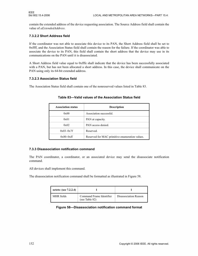
IEEEStd 802.15.4-2006 LOCAL AND METROPOLITAN AREA NETWORKS—PART 15.4:
contain the extended address of the device requesting association. The Source Address field shall contain thevalue of aExtendedAddress.
7.3.2.2 Short Address field
If the coordinator was not able to associate this device to its PAN, the Short Address field shall be set to0xffff, and the Association Status field shall contain the reason for the failure. If the coordinator was able toassociate the device to its PAN, this field shall contain the short address that the device may use in itscommunications on the PAN until it is disassociated.
A Short Address field value equal to 0xfffe shall indicate that the device has been successfully associatedwith a PAN, but has not been allocated a short address. In this case, the device shall communicate on thePAN using only its 64-bit extended address.
7.3.2.3 Association Status field
The Association Status field shall contain one of the nonreserved values listed in Table 83.
7.3.3 Disassociation notification command
The PAN coordinator, a coordinator, or an associated device may send the disassociate notificationcommand.
All devices shall implement this command.
The disassociation notification command shall be formatted as illustrated in Figure 58.
Table 83—Valid values of the Association Status field
Association status Description
0x00 Association successful.
0x01 PAN at capacity.
0x02 PAN access denied.
0x03–0x7f Reserved.
0x80–0xff Reserved for MAC primitive enumeration values.
octets: (see 7.2.2.4) 1 1
MHR fields Command Frame Identifier(see Table 82)
Disassociation Reason
Figure 58—Disassociation notification command format
152 Copyright © 2006 IEEE. All rights reserved.

IEEEWIRELESS MAC AND PHY SPECIFICATIONS FOR LR-WPANS Std 802.15.4-2006
7.3.3.1 MHR fields
The Destination Addressing Mode subfield of the Frame Control field shall be set according to theaddressing mode specified by the corresponding primitive. The Source Addressing Mode subfield shall beset to three (i.e., 64-bit extended addressing).
The Frame Pending subfield of the Frame Control field shall be set to zero and ignored upon reception, andthe Acknowledgment Request subfield shall be set to one.
The PAN ID Compression subfield of the Frame Control field shall be set to one. In accordance with thisvalue of the PAN ID Compression subfield, the Destination PAN Identifier field shall contain the value ofmacPANId, while the Source PAN Identifier field shall be omitted. If the coordinator wants an associateddevice to leave the PAN, then the Destination Address field shall contain the address of the device beingremoved from the PAN. If an associated device wants to leave the PAN, then the Destination Address fieldshall contain the value of either macCoordShortAddress, if the Destination Addressing Mode subfield isequal to two, or macCoordExtendedAddress, if the Destination Addressing Mode subfield is equal to three.The Source Address field shall contain the value of aExtendedAddress.
7.3.3.2 Disassociation Reason field
The Disassociation Reason field shall contain one of the nonreserved values listed in Table 84.
7.3.4 Data request command
The data request command is sent by a device to request data from the PAN coordinator or a coordinator.
There are three cases for which this command is sent. On a beacon-enabled PAN, this command shall besent by a device when macAutoRequest is equal to TRUE and a beacon frame indicating that data arepending for that device is received from its coordinator. The coordinator indicates pending data in its beaconframe by adding the address of the recipient of the data to the Address List field. This command shall also besent when instructed to do so by the next higher layer on reception of the MLME-POLL.request primitive. Inaddition, a device may send this command to the coordinator macResponseWaitTime symbols after theacknowledgment to an association request command.
All devices shall be capable of transmitting this command, although an RFD is not required to be capable ofreceiving it.
The data request command shall be formatted as illustrated in Figure 59.
Table 84—Valid disassociation reason codes
Disassociate reason Description
0x00 Reserved.
0x01 The coordinator wishes the device to leave the PAN.
0x02 The device wishes to leave the PAN.
0x03–0x7f Reserved.
0x80–0xff Reserved for MAC primitive enumeration values.
Copyright © 2006 IEEE. All rights reserved. 153

IEEEStd 802.15.4-2006 LOCAL AND METROPOLITAN AREA NETWORKS—PART 15.4:
If the data request command is being sent in response to the receipt of a beacon frame indicating that data arepending for that device, the Destination Addressing Mode subfield of the Frame Control field may be set tozero (i.e., destination addressing information not present) if the beacon frame indicated in its SuperframeSpecification field (see 7.2.2.1.2) that it originated from the PAN coordinator (see 7.2.1.1.6) or set otherwiseaccording to the coordinator to which the data request command is directed. If the destination addressinginformation is to be included, the Destination Addressing Mode subfield shall be set according to the valueof macCoordShortAddress. If macCoordShortAddress is equal to 0xfffe, extended addressing shall be used:the Destination Addressing Mode subfield shall be set to three, and the Destination Address field shallcontain the value of macCoordExtendedAddress. Otherwise, short addressing shall be used: the DestinationAddressing Mode subfield shall be set to two, and the Destination Address field shall contain the value ofmacCoordShortAddress.
If the data request command is being sent in response to the receipt of a beacon frame indicating that data arepending for that device, the Source Addressing Mode subfield shall be set according to the addressing modeused for the pending address. If the Source Addressing Mode subfield is set to two, short addressing shall beused: the Source Address field shall contain the value of macShortAddress. Otherwise, extended addressingshall be used: the Source Addressing Mode subfield shall be set to three, and the Source Address field shallcontain the value of aExtendedAddress.
If the data request command is triggered by the reception of an MLME-POLL.request primitive from thenext higher layer, then the destination addressing information shall be the same as that contained in theprimitive. The Source Addressing Mode subfield shall be set according to the value of macShortAddress. IfmacShortAddress is less than 0xfffe, short addressing shall be used. Extended addressing shall be usedotherwise.
If the data request command is being sent following the acknowledgment to an association request commandframe, the Destination Addressing Mode subfield of the Frame Control field shall be set according to thecoordinator to which the data request command is directed. If macCoordShortAddress is equal to 0xfffe,extended addressing shall be used. Short addressing shall be used otherwise. The Source Addressing Modesubfield shall be set to use extended addressing.
If the Destination Addressing Mode subfield is set to zero (i.e., destination addressing information notpresent), the PAN ID Compression subfield of the Frame Control field shall be set to zero and the sourcePAN identifier shall contain the value of macPANId. Otherwise, the PAN ID Compression subfield shall beset to one. In this case and in accordance with the PAN ID Compression subfield, the Destination PANIdentifier field shall contain the value of macPANId, while the Source PAN Identifier field shall be omitted.
The Frame Pending subfield of the Frame Control field shall be set to zero and ignored upon reception, andthe Acknowledgment Request subfield shall be set to one.
7.3.5 PAN ID conflict notification command
The PAN ID conflict notification command is sent by a device to the PAN coordinator when a PANidentifier conflict is detected.
octets: (see 7.2.2.4) 1
MHR fields Command Frame Identifier(see Table 82)
Figure 59—Data request command format
154 Copyright © 2006 IEEE. All rights reserved.

IEEEWIRELESS MAC AND PHY SPECIFICATIONS FOR LR-WPANS Std 802.15.4-2006
All devices shall be capable of transmitting this command, although an RFD is not required to be capable ofreceiving it.
The PAN ID conflict notification command shall be formatted as illustrated in Figure 60.
The Destination Addressing Mode and Source Addressing Mode subfields of the Frame Control field shallboth be set to three (i.e., 64-bit extended addressing).
The Frame Pending subfield of the Frame Control field shall be set to zero and ignored upon reception, andthe Acknowledgment Request subfield shall be set to one.
The PAN ID Compression subfield of the Frame Control field shall be set to one. In accordance with thisvalue of the PAN ID Compression subfield, the Destination PAN Identifier field shall contain the value ofmacPANId, while the Source PAN Identifier field shall be omitted. The Destination Address field shallcontain the value of macCoordExtendedAddress. The Source Address field shall contain the value ofaExtendedAddress.
7.3.6 Orphan notification command
The orphan notification command is used by an associated device that has lost synchronization with itscoordinator.
All devices shall be capable of transmitting this command, although an RFD is not required to be capable ofreceiving it.
The orphan notification command shall be formatted as illustrated in Figure 61.
The Source Addressing Mode subfield of the Frame Control field shall be set to three (i.e., 64-bit extendedaddressing). The Destination Addressing Mode subfield shall be set to two (i.e., 16-bit short addressing).
The Frame Pending subfield and Acknowledgment Request subfield of the Frame Control field shall be setto zero and ignored upon reception.
The PAN ID Compression subfield of the Frame Control field shall be set to one. In accordance with thisvalue of the PAN ID Compression subfield, the Destination PAN Identifier field shall contain the value ofthe broadcast PAN identifier (i.e., 0xffff), while the Source PAN Identifier field shall be omitted. The
octets: (see 7.2.2.4) 1
MHR fields Command Frame Identifier(see Table 82)
Figure 60—PAN ID conflict notification command format
octets: 15 1
MHR fields Command Frame Identifier(see Table 82)
Figure 61—Orphan notification command format
Copyright © 2006 IEEE. All rights reserved. 155
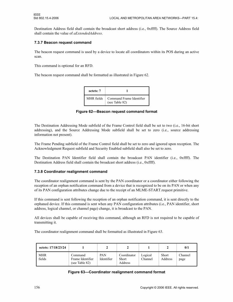
IEEEStd 802.15.4-2006 LOCAL AND METROPOLITAN AREA NETWORKS—PART 15.4:
Destination Address field shall contain the broadcast short address (i.e., 0xffff). The Source Address fieldshall contain the value of aExtendedAddress.
7.3.7 Beacon request command
The beacon request command is used by a device to locate all coordinators within its POS during an activescan.
This command is optional for an RFD.
The beacon request command shall be formatted as illustrated in Figure 62.
The Destination Addressing Mode subfield of the Frame Control field shall be set to two (i.e., 16-bit shortaddressing), and the Source Addressing Mode subfield shall be set to zero (i.e., source addressinginformation not present).
The Frame Pending subfield of the Frame Control field shall be set to zero and ignored upon reception. TheAcknowledgment Request subfield and Security Enabled subfield shall also be set to zero.
The Destination PAN Identifier field shall contain the broadcast PAN identifier (i.e., 0xffff). TheDestination Address field shall contain the broadcast short address (i.e., 0xffff).
7.3.8 Coordinator realignment command
The coordinator realignment command is sent by the PAN coordinator or a coordinator either following thereception of an orphan notification command from a device that is recognized to be on its PAN or when anyof its PAN configuration attributes change due to the receipt of an MLME-START.request primitive.
If this command is sent following the reception of an orphan notification command, it is sent directly to theorphaned device. If this command is sent when any PAN configuration attributes (i.e., PAN identifier, shortaddress, logical channel, or channel page) change, it is broadcast to the PAN.
All devices shall be capable of receiving this command, although an RFD is not required to be capable oftransmitting it.
The coordinator realignment command shall be formatted as illustrated in Figure 63.
octets: 7 1
MHR fields Command Frame Identifier(see Table 82)
Figure 62—Beacon request command format
octets: 17/18/23/24 1 2 2 1 2 0/1
MHRfields
CommandFrame Identifier(see Table 82)
PANIdentifier
CoordinatorShort Address
LogicalChannel
ShortAddress
Channelpage
Figure 63—Coordinator realignment command format
156 Copyright © 2006 IEEE. All rights reserved.

IEEEWIRELESS MAC AND PHY SPECIFICATIONS FOR LR-WPANS Std 802.15.4-2006
7.3.8.1 MHR fields
The Destination Addressing Mode subfield of the Frame Control field shall be set to three (e.g., 64-bitextended addressing) if the command is directed to an orphaned device or set to two (e.g., 16-bit shortaddressing) if it is to be broadcast to the PAN. The Source Addressing Mode subfield of the Frame Controlfield shall be set to three (e.g., 64-bit extended addressing).
The Frame Pending subfield of the Frame Control field shall be set to zero and ignored upon reception.
The Acknowledgment Request subfield of the Frame Control field shall be set to one if the command isdirected to an orphaned device or set to zero if the command is to be broadcast to the PAN.
The Frame Version subfield shall be set to 0x01 if the Channel Page field is present. Otherwise it shall be setas specified in 7.2.3.
The Destination PAN Identifier field shall contain the broadcast PAN identifier (e.g., 0xffff). TheDestination Address field shall contain the extended address of the orphaned device if the command isdirected to an orphaned device. Otherwise, the Destination Address field shall contain the broadcast shortaddress (e.g., 0xffff). The Source PAN Identifier field shall contain the value of macPANId, and the SourceAddress field shall contain the value of aExtendedAddress.
7.3.8.2 PAN Identifier field
The PAN Identifier field shall contain the PAN identifier that the coordinator intends to use for all futurecommunications.
7.3.8.3 Coordinator Short Address field
The Coordinator Short Address field shall contain the value of macShortAddress.
7.3.8.4 Logical Channel field
The Logical Channel field shall contain the logical channel that the coordinator intends to use for all futurecommunications.
7.3.8.5 Short Address field
If the coordinator realignment command is broadcast to the PAN, the Short Address field shall be set to0xffff and ignored on reception.
If the coordinator realignment command is sent directly to an orphaned device, this field shall contain theshort address that the orphaned device shall use to operate on the PAN. If the orphaned device does not havea short address, because it always uses its 64-bit extended address, this field shall contain the value 0xfffe.
7.3.8.6 Channel Page field
The Channel Page field, if present, shall contain the channel page that the coordinator intends to use for allfuture communications. This field may be omitted if the new channel page is the same as the previouschannel page.
Copyright © 2006 IEEE. All rights reserved. 157
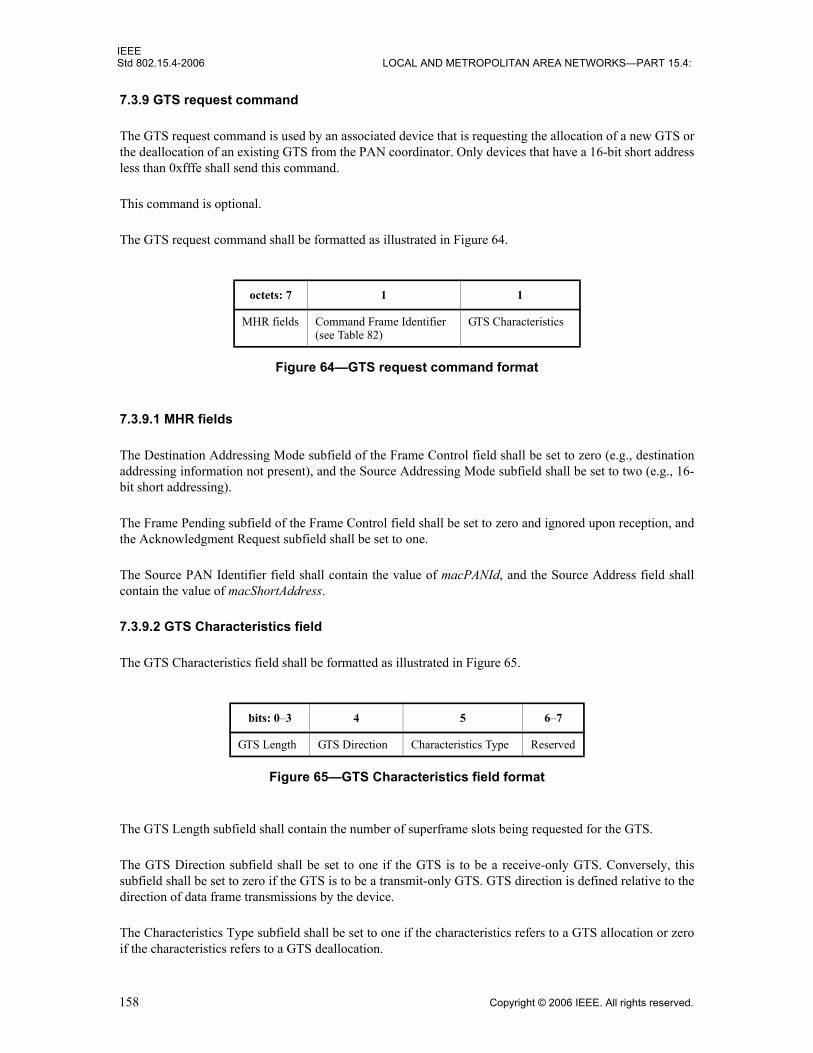
IEEEStd 802.15.4-2006 LOCAL AND METROPOLITAN AREA NETWORKS—PART 15.4:
7.3.9 GTS request command
The GTS request command is used by an associated device that is requesting the allocation of a new GTS orthe deallocation of an existing GTS from the PAN coordinator. Only devices that have a 16-bit short addressless than 0xfffe shall send this command.
This command is optional.
The GTS request command shall be formatted as illustrated in Figure 64.
7.3.9.1 MHR fields
The Destination Addressing Mode subfield of the Frame Control field shall be set to zero (e.g., destinationaddressing information not present), and the Source Addressing Mode subfield shall be set to two (e.g., 16-bit short addressing).
The Frame Pending subfield of the Frame Control field shall be set to zero and ignored upon reception, andthe Acknowledgment Request subfield shall be set to one.
The Source PAN Identifier field shall contain the value of macPANId, and the Source Address field shallcontain the value of macShortAddress.
7.3.9.2 GTS Characteristics field
The GTS Characteristics field shall be formatted as illustrated in Figure 65.
The GTS Length subfield shall contain the number of superframe slots being requested for the GTS.
The GTS Direction subfield shall be set to one if the GTS is to be a receive-only GTS. Conversely, thissubfield shall be set to zero if the GTS is to be a transmit-only GTS. GTS direction is defined relative to thedirection of data frame transmissions by the device.
The Characteristics Type subfield shall be set to one if the characteristics refers to a GTS allocation or zeroif the characteristics refers to a GTS deallocation.
octets: 7 1 1
MHR fields Command Frame Identifier(see Table 82)
GTS Characteristics
Figure 64—GTS request command format
bits: 0–3 4 5 6–7
GTS Length GTS Direction Characteristics Type Reserved
Figure 65—GTS Characteristics field format
158 Copyright © 2006 IEEE. All rights reserved.
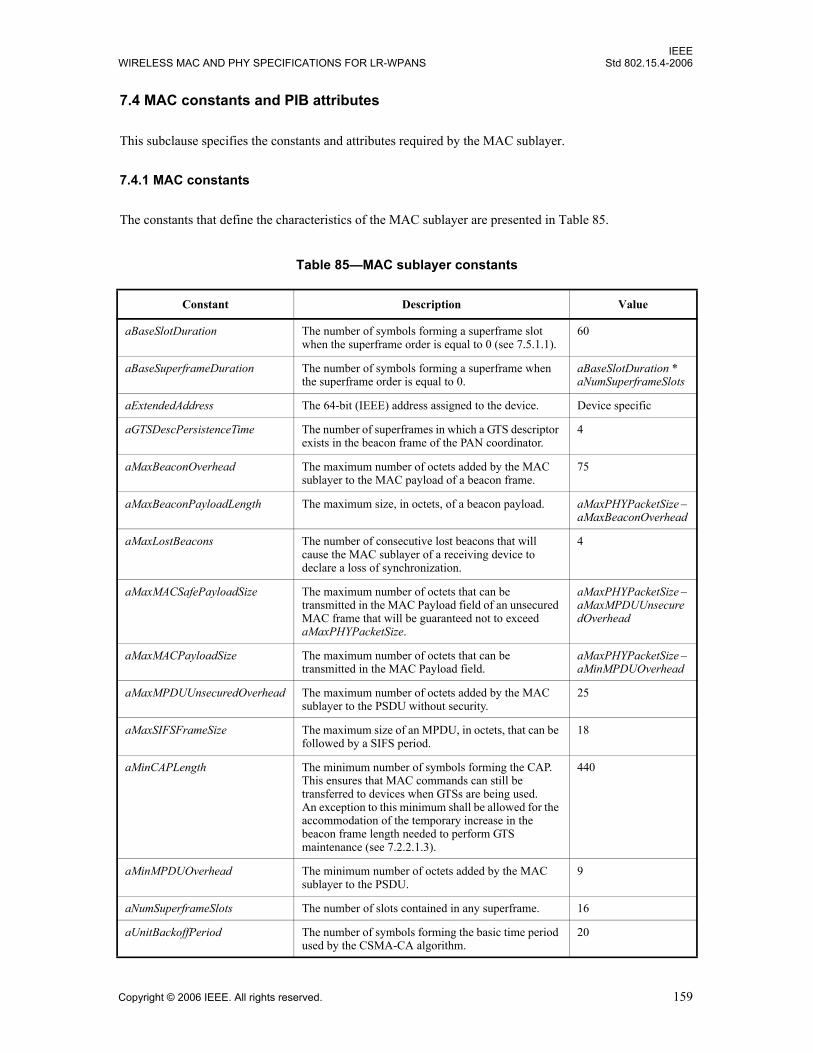
IEEEWIRELESS MAC AND PHY SPECIFICATIONS FOR LR-WPANS Std 802.15.4-2006
7.4 MAC constants and PIB attributes
This subclause specifies the constants and attributes required by the MAC sublayer.
7.4.1 MAC constants
The constants that define the characteristics of the MAC sublayer are presented in Table 85.
Table 85—MAC sublayer constants
Constant Description Value
aBaseSlotDuration The number of symbols forming a superframe slot when the superframe order is equal to 0 (see 7.5.1.1).
60
aBaseSuperframeDuration The number of symbols forming a superframe when the superframe order is equal to 0.
aBaseSlotDuration * aNumSuperframeSlots
aExtendedAddress The 64-bit (IEEE) address assigned to the device. Device specific
aGTSDescPersistenceTime The number of superframes in which a GTS descriptor exists in the beacon frame of the PAN coordinator.
4
aMaxBeaconOverhead The maximum number of octets added by the MAC sublayer to the MAC payload of a beacon frame.
75
aMaxBeaconPayloadLength The maximum size, in octets, of a beacon payload. aMaxPHYPacketSize – aMaxBeaconOverhead
aMaxLostBeacons The number of consecutive lost beacons that will cause the MAC sublayer of a receiving device to declare a loss of synchronization.
4
aMaxMACSafePayloadSize The maximum number of octets that can be transmitted in the MAC Payload field of an unsecured MAC frame that will be guaranteed not to exceed aMaxPHYPacketSize.
aMaxPHYPacketSize – aMaxMPDUUnsecuredOverhead
aMaxMACPayloadSize The maximum number of octets that can be transmitted in the MAC Payload field.
aMaxPHYPacketSize – aMinMPDUOverhead
aMaxMPDUUnsecuredOverhead The maximum number of octets added by the MAC sublayer to the PSDU without security.
25
aMaxSIFSFrameSize The maximum size of an MPDU, in octets, that can be followed by a SIFS period.
18
aMinCAPLength The minimum number of symbols forming the CAP. This ensures that MAC commands can still be transferred to devices when GTSs are being used.An exception to this minimum shall be allowed for the accommodation of the temporary increase in the beacon frame length needed to perform GTS maintenance (see 7.2.2.1.3).
440
aMinMPDUOverhead The minimum number of octets added by the MAC sublayer to the PSDU.
9
aNumSuperframeSlots The number of slots contained in any superframe. 16
aUnitBackoffPeriod The number of symbols forming the basic time period used by the CSMA-CA algorithm.
20
Copyright © 2006 IEEE. All rights reserved. 159

IEEEStd 802.15.4-2006 LOCAL AND METROPOLITAN AREA NETWORKS—PART 15.4:
7.4.2 MAC PIB attributes
The MAC PIB comprises the attributes required to manage the MAC sublayer of a device. The attributescontained in the MAC PIB are presented in Table 86. Attributes marked with a dagger (†) are read-onlyattributes (i.e., attribute can only be set by the MAC sublayer), which can be read by the next higher layerusing the MLME-GET.request primitive. All other attributes can be read or written by the next higher layerusing the MLME-GET.request or MLME-SET.request primitives, respectively. Attributes marked with adiamond ( ) are optional for an RFD; attributes marked with an asterisk (*) are optional for both devicetypes (i.e., RFD and FFD).
The read-only attribute macAckWaitDuration is dependent on a combination of constants and PHY PIBattributes. The formula for relating the constants and attributes is shown in Equation (13).
macAckWaitDuration = (13)
where 6 represents the number of PHY header octets plus the number of PSDU octets in an
acknowledgment frame.
The attribute macMaxFrameTotalWaitTime may be set by the next higher layer and is dependent upon acombination of PHY and MAC PIB attributes and constants. The formula relating the attributes andconstants is shown in Equation (14):
macMaxFrameTotalWaitTime = (14)
where m is min(macMaxBE-macMinBE, macMaxCSMABackoffs).
Table 86—MAC PIB attributes
Attribute Identifier Type Range Description Default
macAckWaitDuration† 0x40 Integer See Equation (13)
The maximum number of symbols to wait for an acknowledgment frame to arrive following a transmitted data frame.
This value is dependent on the supported PHY, which determines both the selected logical channel and channel page. The calculated value is the time to commence transmitting the ACK plus the length of the ACK frame. The commencement time is described in 7.5.6.4.2.
Dependent on currently selected PHY, indicated by phy-Current-Page
aUnitBackoffPeriod aTurnaroundTime phySHRDuration 6 phySymbolsPerOctet⋅+ + +
2macMinBE k+
k 0=
m 1–
∑⎝ ⎠⎜ ⎟⎜ ⎟⎛ ⎞
2macMaxBE 1–( ) macMaxCSMABackoffs m–( )⋅+ aUnitBackoffPeriod phyMaxFrameDuration+•
160 Copyright © 2006 IEEE. All rights reserved.

IEEEWIRELESS MAC AND PHY SPECIFICATIONS FOR LR-WPANS Std 802.15.4-2006
macAssociatedPAN-Coord
0x56 Boolean TRUE or FALSE
Indication of whether the device is associated to the PAN through the PAN coordinator. A value of TRUE indicates the device has associated through the PAN coordinator. Otherwise, the value is set to FALSE.
FALSE
macAssociation-Permit
0x41 Boolean TRUE or FALSE
Indication of whether a coordinator is currently allowing association. A value of TRUE indicates that association is permitted.
FALSE
macAutoRequest 0x42 Boolean TRUE or FALSE
Indication of whether a device automatically sends a data request command if its address is listed in the beacon frame. A value of TRUE indicates that the data request command is automatically sent.
This attribute also affects the generation of the MLME-BEACON-NOTIFY.indication primitive (see 7.1.5.1.2).
TRUE
macBattLifeExt 0x43 Boolean TRUE or FALSE
Indication of whether BLE, through the reduction of coordinator receiver operation time during the CAP, is enabled. A value of TRUE indicates that it is enabled. Also, see 7.5.1.4 for an explanation of how this attribute affects the backoff exponent in the CSMA-CA algorithm.
FALSE
Table 86—MAC PIB attributes (continued)
Attribute Identifier Type Range Description Default
Copyright © 2006 IEEE. All rights reserved. 161

IEEEStd 802.15.4-2006 LOCAL AND METROPOLITAN AREA NETWORKS—PART 15.4:
macBattLifeExtPeriods 0x44 Integer 6-41 In BLE mode, the number of backoff periods during which the receiver is enabled after the IFS following a beacon.
This value is dependent on the supported PHY and is the sum of three terms:
Term 1: The value , where x is the maximum
value of macMinBE in BLE mode (equal to two). This
term is thus equal to 3 backoff periods.
Term 2: The duration of the initial contention window
length (see 7.5.1.4). This term is thus equal to 2 backoff
periods.
Term 3: The Preamble field length and the SFD field
length of the supported PHY (see Table 19 and Table 20 in Clause 6), summed together
and rounded up (if necessary) to an integer number of back-
off periods.
Dependent on currently selected PHY, indicated by phy-Current-Page
macBeaconPayload 0x45 Set of octets
— The contents of the beacon payload.
NULL
macBeaconPayload-Length
0x46 Integer 0 – aMax-Beacon-PayloadLength
The length, in octets, of the beacon payload.
0
macBeaconOrder 0x47 Integer 0–15 Specification of how often the coordinator transmits its beacon. If BO = 15, the coordinator will not transmit a periodic beacon. See 7.5.1.1 for an explanation of the relationship between the beacon order and the beacon interval.
15
Table 86—MAC PIB attributes (continued)
Attribute Identifier Type Range Description Default
2x 1–
162 Copyright © 2006 IEEE. All rights reserved.

IEEEWIRELESS MAC AND PHY SPECIFICATIONS FOR LR-WPANS Std 802.15.4-2006
macBeaconTxTime† 0x48 Integer 0x000000–0xffffff
The time that the device transmitted its last beacon frame, in symbol periods. The measurement shall be taken at the same symbol boundary within every transmitted beacon frame, the location of which is implementation specific.
This is a 24-bit value, and the precision of this value shall be a minimum of 20 bits, with the lowest four bits being the least significant.
0x000000
macBSN 0x49 Integer 0x00–0xff The sequence number added to the transmitted beacon frame.
Random value from within the range
macCoordExtended-Address
0x4a IEEE address
An extended 64-bit IEEE address
The 64-bit address of the coordinator through which the device is associated.
—
macCoordShort-Address
0x4b Integer 0x0000–0xffff The 16-bit short address assigned to the coordinator through which the device is associated. A value of0xfffe indicates that the coordinator is only using its 64-bit extended address. A value of 0xffff indicates that this value is unknown.
0xffff
macDSN 0x4c Integer 0x00–0xff The sequence number added to the transmitted data or MAC command frame.
Random value from within the range
macGTSPermit* 0x4d Boolean TRUE or FALSE
TRUE if the PAN coordinator is to accept GTS requests. FALSE otherwise.
TRUE
macMaxBE 0x57 Integer 3–8 The maximum value of the backoff exponent, BE, in the CSMA-CA algorithm. See 7.5.1.4 for a detailed explanation of the backoff exponent.
5
macMaxCSMABackoffs 0x4e Integer 0–5 The maximum number of backoffs the CSMA-CA algorithm will attempt before declaring a channel access failure.
4
Table 86—MAC PIB attributes (continued)
Attribute Identifier Type Range Description Default
Copyright © 2006 IEEE. All rights reserved. 163

IEEEStd 802.15.4-2006 LOCAL AND METROPOLITAN AREA NETWORKS—PART 15.4:
macMaxFrameTotal-WaitTime
0x58 Integer See Equation (14)
The maximum number of CAP symbols in a beacon-enabled PAN, or symbols in a nonbeacon-enabled PAN, to wait either for a frame intended as a response to a data request frame or for a broadcast frame following a beacon with the Frame Pending subfield set to one.
This attribute, which shall only be set by the next higher layer, is dependent upon macMinBE, macMaxBE, macMaxCSMABackoffs and the number of symbols per octet. See 7.4.2 for the formula relating the attributes.
Dependent on currently selected PHY, indicated by phy-Current-Page
macMaxFrameRetries 0x59 Integer 0–7 The maximum number of retries allowed after a transmission failure.
3
macMinBE 0x4f Integer 0–macMaxBE The minimum value of the backoff exponent (BE) in the CSMA-CA algorithm. See 7.5.1.4 for a detailed explanation of the backoff exponent.
3
macMinLIFSPeriod† Integer See Table 3 in Clause 6
The minimum number of symbols forming a LIFS period.
Dependent on currently selected PHY, indicated by phy-Current-Page
macMinSIFSPeriod† Integer See Table 3 in Clause 6
The minimum number of symbols forming a SIFS period.
Dependent on currently selected PHY, indicated by phy-Current-Page
macPANId 0x50 Integer 0x0000–0xffff The 16-bit identifier of the PAN on which the device is operating. If this value is 0xffff, the device is not associated.
0xffff
Table 86—MAC PIB attributes (continued)
Attribute Identifier Type Range Description Default
164 Copyright © 2006 IEEE. All rights reserved.
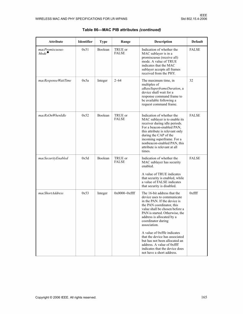
IEEEWIRELESS MAC AND PHY SPECIFICATIONS FOR LR-WPANS Std 802.15.4-2006
macPromiscuous-Mode
0x51 Boolean TRUE or FALSE
Indication of whether the MAC sublayer is in a promiscuous (receive all) mode. A value of TRUE indicates that the MAC sublayer accepts all frames received from the PHY.
FALSE
macResponseWaitTime 0x5a Integer 2–64 The maximum time, in multiples of aBaseSuperframeDuration, a device shall wait for a response command frame to be available following a request command frame.
32
macRxOnWhenIdle 0x52 Boolean TRUE or FALSE
Indication of whether the MAC sublayer is to enable its receiver during idle periods. For a beacon-enabled PAN, this attribute is relevant only during the CAP of the incoming superframe. For a nonbeacon-enabled PAN, this attribute is relevant at all times.
FALSE
macSecurityEnabled 0x5d Boolean TRUE or FALSE
Indication of whether the MAC sublayer has security enabled.
A value of TRUE indicates that security is enabled, while a value of FALSE indicates that security is disabled.
FALSE
macShortAddress 0x53 Integer 0x0000–0xffff The 16-bit address that the device uses to communicate in the PAN. If the device is the PAN coordinator, this value shall be chosen before a PAN is started. Otherwise, the address is allocated by a coordinator during association.
A value of 0xfffe indicates that the device has associated but has not been allocated an address. A value of 0xffff indicates that the device does not have a short address.
0xffff
Table 86—MAC PIB attributes (continued)
Attribute Identifier Type Range Description Default
Copyright © 2006 IEEE. All rights reserved. 165

IEEEStd 802.15.4-2006 LOCAL AND METROPOLITAN AREA NETWORKS—PART 15.4:
7.5 MAC functional description
This subclause provides a detailed description of the MAC functionality. Subclause 7.5.1 describes thefollowing two mechanisms for channel access: contention based and contention free. Contention-basedaccess allows devices to access the channel in a distributed fashion using a CSMA-CA backoff algorithm.Contention-free access is controlled entirely by the PAN coordinator through the use of GTSs.
The mechanisms used for starting and maintaining a PAN are described in 7.5.2. Channel scanning is usedby a device to assess the current state of a channel (or channels), locate all beacons within its POS, or locatea particular beacon with which it has lost synchronization. Before starting a new PAN, the results of achannel scan can be used to select an appropriate logical channel and channel page, as well as a PANidentifier that is not being used by any other PAN in the area. Because it is still possible for the POS of twoPANs with the same PAN identifier to overlap, a procedure exists to detect and resolve this situation.Following a channel scan and suitable PAN identifier selection, an FFD can begin operating as the PAN
macSuperframe-Order†
0x54 Integer 0–15 The length of the active portion of the outgoing superframe, including the beacon frame. If superframe order, SO, = 15, the superframe will not be active following the beacon. See 7.5.1.1 for an explanation of the relationship between the superframe order and the superframe duration.
15
macSyncSymbolOffset† 0x5b Integer 0x000–0x100 for the 2.4 GHz PHY
0x000–0x400 for the 868/915 MHz PHY
The offset, measured in symbols, between the symbol boundary at which the MLME captures the timestamp of each transmitted or received frame, and the onset of the first symbol past the SFD, namely, the first symbol of the Length field.
Imple-mentation specific
macTimestamp-Supported†
0x5c Boolean TRUE or FALSE
Indication of whether the MAC sublayer supports the optional timestamping feature for incoming and outgoing data frames.
Imple-mentation specific
macTransaction-PersistenceTime
0x55 Integer 0x0000–0xffff The maximum time (in unit periods) that a transaction is stored by a coordinator and indicated in its beacon.
The unit period is governed by macBeaconOrder, BO, as follows: For 0 ≤ BO ≤ 14, the unit period will be aBase-SuperframeDuration * 2BO. For BO = 15, the unit period will be aBaseSuperframe-Duration.
0x01f4
Table 86—MAC PIB attributes (continued)
Attribute Identifier Type Range Description Default
166 Copyright © 2006 IEEE. All rights reserved.
IEEEWIRELESS MAC AND PHY SPECIFICATIONS FOR LR-WPANS Std 802.15.4-2006
coordinator. Also described in the subclause is a method to allow a beaconing FFD to discover other suchdevices during normal operations, i.e., when not scanning.
The mechanisms to allow devices to join or leave a PAN are defined in 7.5.3. The association proceduredescribes the conditions under which a device may join a PAN and the conditions necessary for acoordinator to permit devices to join. Also described is the disassociation procedure, which can be initiatedby the associated device or its coordinator.
The mechanisms to allow devices to acquire and maintain synchronization with a coordinator are describedin 7.5.4. Synchronization on a beacon-enabled PAN is described after first explaining how a coordinatorgenerates beacon frames. Following this explanation, synchronization on a nonbeacon-enabled PAN isdescribed. Also described is a procedure to reestablish communication between a device and its coordinator,as it is possible that a device may lose synchronization in the case of either a beacon-enabled or anonbeacon-enabled PAN.
This standard has been designed so that application data transfers can be controlled by the devices on a PANrather than by the coordinator. The procedures the coordinator uses to handle multiple transactions whilepreserving this requirement are described in 7.5.5.
The mechanisms for transmitting, receiving, and acknowledging frames, including frames sent usingindirect transmission, are described in 7.5.6. In addition, methods for retransmitting frames are alsodescribed.
The mechanisms for allocating and deallocating a GTS are described in 7.5.7. The deallocation process mayresult in the fragmentation of the GTS space, i.e., an unused slot or slots. The subclause describes amechanism to resolve fragmentation.
The MAC sublayer uses the mechanisms described in 7.5.8 for all incoming and outgoing frames.
Throughout this subclause, the receipt of a frame is defined as the successful receipt of the frame by thePHY and the successful verification of the FCS by the MAC sublayer, as described in 7.2.1.9.
7.5.1 Channel access
This subclause describes the mechanisms for accessing the physical radio channel.
7.5.1.1 Superframe structure
A coordinator on a PAN can optionally bound its channel time using a superframe structure. A superframe isbounded by the transmission of a beacon frame and can have an active portion and an inactive portion. Thecoordinator may enter a low-power (sleep) mode during the inactive portion.
The structure of this superframe is described by the values of macBeaconOrder and macSuperframeOrder.The MAC PIB attribute macBeaconOrder, describes the interval at which the coordinator shall transmit itsbeacon frames. The value of macBeaconOrder, BO, and the beacon interval, BI, are related as follows: for 0≤ BO ≤ 14, BI = aBaseSuperframeDuration * 2BO symbols. If BO = 15, the coordinator shall not transmitbeacon frames except when requested to do so, such as on receipt of a beacon request command. The valueof macSuperframeOrder shall be ignored if BO = 15.
The MAC PIB attribute macSuperframeOrder describes the length of the active portion of the superframe,which includes the beacon frame. The value of macSuperframeOrder, SO, and the superframe duration, SD,are related as follows: for 0 ≤ SO ≤ BO ≤ 14, SD = aBaseSuperframeDuration * 2SO symbols. If SO = 15, thesuperframe shall not remain active after the beacon. If BO = 15, the superframe shall not exist (the value of
Copyright © 2006 IEEE. All rights reserved. 167

IEEEStd 802.15.4-2006 LOCAL AND METROPOLITAN AREA NETWORKS—PART 15.4:
macSuperframeOrder shall be ignored), and macRxOnWhenIdle shall define whether the receiver is enabledduring periods of transceiver inactivity.
The active portion of each superframe shall be divided into aNumSuperframeSlots equally spaced slots ofduration 2SO * aBaseSlotDuration and is composed of three parts: a beacon, a CAP and a CFP. The beaconshall be transmitted, without the use of CSMA, at the start of slot 0, and the CAP shall commenceimmediately following the beacon. The start of slot 0 is defined as the point at which the first symbol of thebeacon PPDU is transmitted. The CFP, if present, follows immediately after the CAP and extends to the endof the active portion of the superframe. Any allocated GTSs shall be located within the CFP.
The MAC sublayer shall ensure that the integrity of the superframe timing is maintained, e.g., compensatingfor clock drift error.
PANs that wish to use the superframe structure (referred to as a beacon-enabled PAN) shall setmacBeaconOrder to a value between 0 and 14, both inclusive, and macSuperframeOrder to a value between0 and the value of macBeaconOrder, both inclusive.
PANs that do not wish to use the superframe structure (referred to as a nonbeacon-enabled PAN) shall setboth macBeaconOrder and macSuperframeOrder to 15. In this case, a coordinator shall not transmitbeacons, except upon receipt of a beacon request command; all transmissions, with the exception ofacknowledgment frames and any data frame that quickly follows the acknowledgment of a data requestcommand (see 7.5.6.3), shall use an unslotted CSMA-CA mechanism to access the channel. In addition,GTSs shall not be permitted.
An example of a superframe structure is shown in Figure 66. In this case, the beacon interval, BI, is twice aslong as the active superframe duration, SD, and the CFP contains two GTSs.
7.5.1.1.1 Contention access period (CAP)
The CAP shall start immediately following the beacon and complete before the beginning of the CFP on asuperframe slot boundary. If the CFP is zero length, the CAP shall complete at the end of the active portionof the superframe. The CAP shall be at least aMinCAPLength symbols, unless additional space is needed totemporarily accommodate the increase in the beacon frame length needed to perform GTS maintenance (see7.2.2.1.3), and shall shrink or grow dynamically to accommodate the size of the CFP.
All frames, except acknowledgment frames and any data frame that quickly follows the acknowledgment ofa data request command (see 7.5.6.3), transmitted in the CAP shall use a slotted CSMA-CA mechanism to
Figure 66—An example of the superframe structure
GTS GTS Inactive
Beacon Beacon
CAP CFP
SD = aBaseSuperframeDuration*2SO symbols(Active)
BI = aBaseSuperframeDuration*2BO symbols
0 1 2 3 4 5 6 7 8 9 10 11 12 13 14 15
168 Copyright © 2006 IEEE. All rights reserved.
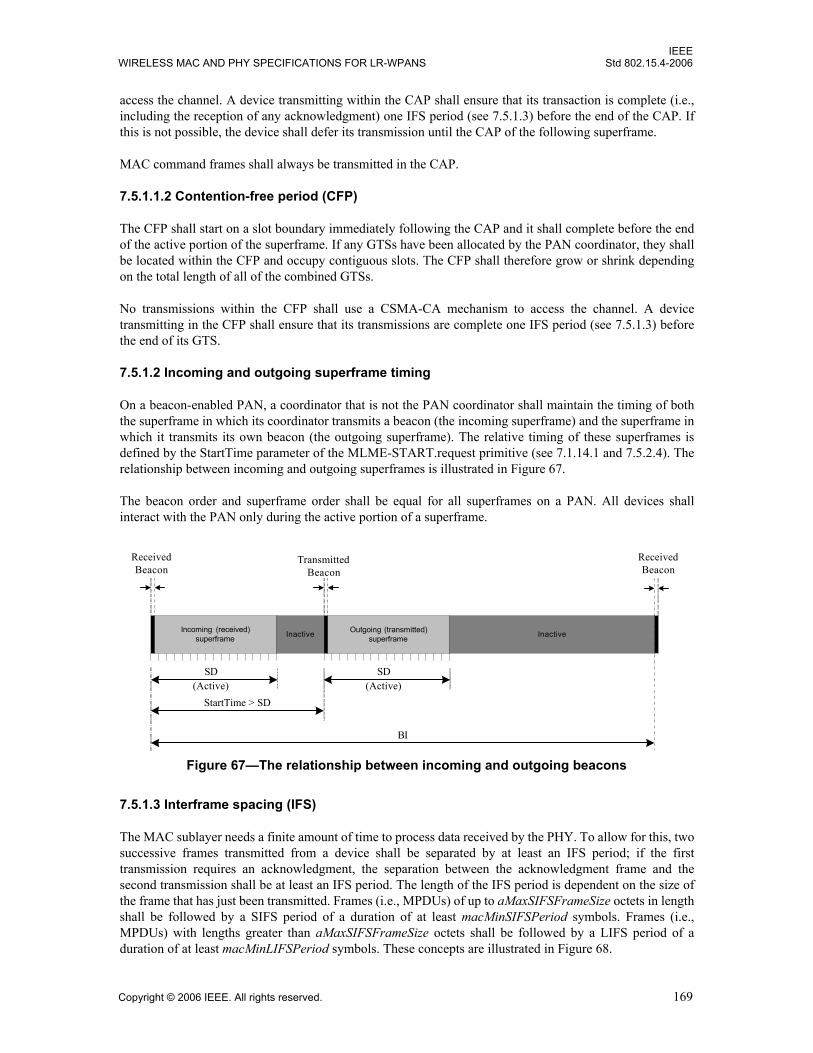
IEEEWIRELESS MAC AND PHY SPECIFICATIONS FOR LR-WPANS Std 802.15.4-2006
access the channel. A device transmitting within the CAP shall ensure that its transaction is complete (i.e.,including the reception of any acknowledgment) one IFS period (see 7.5.1.3) before the end of the CAP. Ifthis is not possible, the device shall defer its transmission until the CAP of the following superframe.
MAC command frames shall always be transmitted in the CAP.
7.5.1.1.2 Contention-free period (CFP)
The CFP shall start on a slot boundary immediately following the CAP and it shall complete before the endof the active portion of the superframe. If any GTSs have been allocated by the PAN coordinator, they shallbe located within the CFP and occupy contiguous slots. The CFP shall therefore grow or shrink dependingon the total length of all of the combined GTSs.
No transmissions within the CFP shall use a CSMA-CA mechanism to access the channel. A devicetransmitting in the CFP shall ensure that its transmissions are complete one IFS period (see 7.5.1.3) beforethe end of its GTS.
7.5.1.2 Incoming and outgoing superframe timing
On a beacon-enabled PAN, a coordinator that is not the PAN coordinator shall maintain the timing of boththe superframe in which its coordinator transmits a beacon (the incoming superframe) and the superframe inwhich it transmits its own beacon (the outgoing superframe). The relative timing of these superframes isdefined by the StartTime parameter of the MLME-START.request primitive (see 7.1.14.1 and 7.5.2.4). Therelationship between incoming and outgoing superframes is illustrated in Figure 67.
The beacon order and superframe order shall be equal for all superframes on a PAN. All devices shallinteract with the PAN only during the active portion of a superframe.
7.5.1.3 Interframe spacing (IFS)
The MAC sublayer needs a finite amount of time to process data received by the PHY. To allow for this, twosuccessive frames transmitted from a device shall be separated by at least an IFS period; if the firsttransmission requires an acknowledgment, the separation between the acknowledgment frame and thesecond transmission shall be at least an IFS period. The length of the IFS period is dependent on the size ofthe frame that has just been transmitted. Frames (i.e., MPDUs) of up to aMaxSIFSFrameSize octets in lengthshall be followed by a SIFS period of a duration of at least macMinSIFSPeriod symbols. Frames (i.e.,MPDUs) with lengths greater than aMaxSIFSFrameSize octets shall be followed by a LIFS period of aduration of at least macMinLIFSPeriod symbols. These concepts are illustrated in Figure 68.
Figure 67—The relationship between incoming and outgoing beacons
Incoming (received)superframe
ReceivedBeacon
ReceivedBeacon
(Active)
BI
Outgoing (transmitted)superframe
TransmittedBeacon
SD
StartTime > SD(Active)
SD
InactiveInactive
Copyright © 2006 IEEE. All rights reserved. 169

IEEEStd 802.15.4-2006 LOCAL AND METROPOLITAN AREA NETWORKS—PART 15.4:
The CSMA-CA algorithm shall take this requirement into account for transmissions in the CAP.
7.5.1.4 CSMA-CA algorithm
The CSMA-CA algorithm shall be used before the transmission of data or MAC command framestransmitted within the CAP, unless the frame can be quickly transmitted following the acknowledgment of adata request command (see 7.5.6.3 for timing requirements). The CSMA-CA algorithm shall not be used forthe transmission of beacon frames in a beacon-enabled PAN, acknowledgment frames, or data framestransmitted in the CFP.
If periodic beacons are being used in the PAN, the MAC sublayer shall employ the slotted version of theCSMA-CA algorithm for transmissions in the CAP of the superframe. Conversely, if periodic beacons arenot being used in the PAN or if a beacon could not be located in a beacon-enabled PAN, the MAC sublayershall transmit using the unslotted version of the CSMA-CA algorithm. In both cases, the algorithm isimplemented using units of time called backoff periods, where one backoff period shall be equal toaUnitBackoffPeriod symbols.
In slotted CSMA-CA, the backoff period boundaries of every device in the PAN shall be aligned with thesuperframe slot boundaries of the PAN coordinator, i.e., the start of the first backoff period of each device isaligned with the start of the beacon transmission. In slotted CSMA-CA, the MAC sublayer shall ensure thatthe PHY commences all of its transmissions on the boundary of a backoff period. In unslotted CSMA-CA,the backoff periods of one device are not related in time to the backoff periods of any other device in thePAN.
Each device shall maintain three variables for each transmission attempt: NB, CW and BE. NB is the numberof times the CSMA-CA algorithm was required to backoff while attempting the current transmission; thisvalue shall be initialized to zero before each new transmission attempt. CW is the contention window length,defining the number of backoff periods that need to be clear of channel activity before the transmission cancommence; this value shall be initialized to two before each transmission attempt and reset to two each timethe channel is assessed to be busy. The CW variable is only used for slotted CSMA-CA. BE is the backoffexponent, which is related to how many backoff periods a device shall wait before attempting to assess achannel. In unslotted systems, or slotted systems with the received BLE subfield (see Figure 47) set to zero,BE shall be initialized to the value of macMinBE. In slotted systems with the received BLE subfield set toone, this value shall be initialized to the lesser of two and the value of macMinBE. Note that if macMinBE isset to zero, collision avoidance will be disabled during the first iteration of this algorithm.
Figure 68—IFS
Long frame ACK Short frame ACK
tack LIFS tack SIFS
Acknowledged transmission
Long frame Short frame
LIFS SIFS
Unacknowledged transmission
Where aTurnaroundTime ≤ tack ≤ (aTurnaroundTime + aUnitBackoffPeriod)
170 Copyright © 2006 IEEE. All rights reserved.
IEEEWIRELESS MAC AND PHY SPECIFICATIONS FOR LR-WPANS Std 802.15.4-2006
Although the receiver of the device is enabled during the CCA analysis portion of this algorithm, the devicemay discard any frames received during this time.
Figure 69 illustrates the steps of the CSMA-CA algorithm. When using slotted CSMA-CA, the MACsublayer shall first initialize NB, CW, and BE and then locate the boundary of the next backoff period[step (1)]. For unslotted CSMA-CA, the MAC sublayer shall initialize NB and BE and then proceed directlyto step (2).
The MAC sublayer shall delay for a random number of complete backoff periods in the range 0 to 2BE – 1[step (2)] and then request that the PHY perform a CCA [step (3)]. In a slotted CSMA-CA system, the CCAshall start on a backoff period boundary. In an unslotted CSMA-CA system, the CCA shall startimmediately.
In a slotted CSMA-CA system with the BLE subfield set to zero, the MAC sublayer shall ensure that, afterthe random backoff, the remaining CSMA-CA operations can be undertaken and the entire transaction canbe transmitted before the end of the CAP. Note that any bit padding used by the supported PHY (see 6.7.2.2)must be considered in making this determination. If the number of backoff periods is greater than theremaining number of backoff periods in the CAP, the MAC sublayer shall pause the backoff countdown atthe end of the CAP and resume it at the start of the CAP in the next superframe. If the number of backoffperiods is less than or equal to the remaining number of backoff periods in the CAP, the MAC sublayer shallapply its backoff delay and then evaluate whether it can proceed. The MAC sublayer shall proceed if theremaining CSMA-CA algorithm steps (i.e., two CCA analyses), the frame transmission, and anyacknowledgment can be completed before the end of the CAP. If the MAC sublayer can proceed, it shallrequest that the PHY perform the CCA in the current superframe. If the MAC sublayer cannot proceed, itshall wait until the start of the CAP in the next superframe and apply a further random backoff delay[step (2)] before evaluating whether it can proceed again.
In a slotted CSMA-CA system with the BLE subfield set to one, the MAC sublayer shall ensure that, afterthe random backoff, the remaining CSMA-CA operations can be undertaken and the entire transaction canbe transmitted before the end of the CAP. The backoff countdown shall only occur during the firstmacBattLifeExtPeriods full backoff periods after the end of the IFS period following the beacon. The MACsublayer shall proceed if the remaining CSMA-CA algorithm steps (two CCA analyses), the frametransmission, and any acknowledgment can be completed before the end of the CAP, and the frametransmission will start in one of the first macBattLifeExtPeriods full backoff periods after the IFS periodfollowing the beacon. If the MAC sublayer can proceed, it shall request that the PHY perform the CCA inthe current superframe. If the MAC sublayer cannot proceed, it shall wait until the start of the CAP in thenext superframe and apply a further random backoff delay [step (2)] before evaluating whether it canproceed again.
If the channel is assessed to be busy [step (4)], the MAC sublayer shall increment both NB and BE by one,ensuring that BE shall be no more than macMaxBE. The MAC sublayer in a slotted CSMA-CA system shallalso reset CW to two. If the value of NB is less than or equal to macMaxCSMABackoffs, the CSMA-CAalgorithm shall return to step (2). If the value of NB is greater than macMaxCSMABackoffs, the CSMA-CAalgorithm shall terminate with a channel access failure status.
If the channel is assessed to be idle [step (5)], the MAC sublayer in a slotted CSMA-CA system shall ensurethat the contention window has expired before commencing transmission. To do this, the MAC sublayershall first decrement CW by one and then determine whether it is equal to zero. If it is not equal to zero, theCSMA-CA algorithm shall return to step (3). If it is equal to zero, the MAC sublayer shall begintransmission of the frame on the boundary of the next backoff period. If the channel is assessed to be idle inan unslotted CSMA-CA system, the MAC sublayer shall begin transmission of the frame immediately.
Copyright © 2006 IEEE. All rights reserved. 171

IEEEStd 802.15.4-2006 LOCAL AND METROPOLITAN AREA NETWORKS—PART 15.4:
7.5.2 Starting and maintaining PANs
This subclause specifies the procedures for scanning through channels, identifying PAN identifier conflicts,and starting PANs.
7.5.2.1 Scanning through channels
All devices shall be capable of performing passive and orphan scans across a specified list of channels. Inaddition, an FFD shall be able to perform ED and active scans. The next higher layer should submit a scan
Figure 69—CSMA-CA algorithm
172 Copyright © 2006 IEEE. All rights reserved.

IEEEWIRELESS MAC AND PHY SPECIFICATIONS FOR LR-WPANS Std 802.15.4-2006
request for a particular channel page containing a list of channels chosen only from the channels specified byphyChannelsSupported for that particular channel page.
A device is instructed to begin a channel scan through the MLME-SCAN.request primitive. Channels arescanned in order from the lowest channel number to the highest. For the duration of the scan, the device shallsuspend beacon transmissions, if applicable, and shall only accept frames received over the PHY dataservice that are relevant to the scan being performed. Upon the conclusion of the scan, the device shallrecommence beacon transmissions. The results of the scan shall be returned via the MLME-SCAN.confirmprimitive.
7.5.2.1.1 ED channel scan
An ED scan allows a device to obtain a measure of the peak energy in each requested channel. This could beused by a prospective PAN coordinator to select a channel on which to operate prior to starting a new PAN.During an ED scan, the MAC sublayer shall discard all frames received over the PHY data service.
An ED scan over a specified set of logical channels is requested using the MLME-SCAN.request primitivewith the ScanType parameter set to indicate an ED scan. For each logical channel, the MLME shall firstswitch to the channel, by setting phyCurrentChannel and phyCurrentPage accordingly, and then repeatedlyperform an ED measurement for [aBaseSuperframeDuration * (2n + 1)] symbols, where n is the value of theScanDuration parameter in the MLME-SCAN.request primitive. An ED measurement is performed by theMLME issuing the PLME-ED.request (see 6.2.2.3), which is guaranteed to return a value. The maximumED measurement obtained during this period shall be noted before moving on to the next channel in thechannel list. A device shall be able to store between one and an implementation-specified maximum numberof channel ED measurements.
The ED scan shall terminate when either the number of channel ED measurements stored equals theimplementation-specified maximum or energy has been measured on each of the specified logical channels.
7.5.2.1.2 Active channel scan
An active scan allows a device to locate any coordinator transmitting beacon frames within its POS. Thiscould be used by a prospective PAN coordinator to select a PAN identifier prior to starting a new PAN, or itcould be used by a device prior to association.
During an active scan, the MAC sublayer shall discard all frames received over the PHY data service thatare not beacon frames. If a beacon frame is received that contains the address of the scanning device in itslist of pending addresses, the scanning device shall not attempt to extract the pending data.
Before commencing an active scan, the MAC sublayer shall store the value of macPANId and then set it to0xffff for the duration of the scan. This enables the receive filter to accept all beacons rather than just thebeacons from its current PAN (see 7.5.6.2). On completion of the scan, the MAC sublayer shall restore thevalue of macPANId to the value stored before the scan began.
An active scan over a specified set of logical channels is requested using the MLME-SCAN.requestprimitive with the ScanType parameter set to indicate an active scan. For each logical channel, the deviceshall first switch to the channel, by setting phyCurrentChannel and phyCurrentPage accordingly, and send abeacon request command (see 7.3.7). Upon successful transmission of the beacon request command, thedevice shall enable its receiver for at most [aBaseSuperframeDuration * (2n + 1)] symbols, where n is thevalue of the ScanDuration parameter. During this time, the device shall reject all nonbeacon frames andrecord the information contained in all unique beacons in a PAN descriptor structure (see Table 55 in7.1.5.1.1). If a beacon frame is received when macAutoRequest is set to TRUE, the list of PAN descriptorstructures shall be stored by the MAC sublayer until the scan is complete; at this time, the list shall be sent tothe next higher layer in the PANDescriptorList parameter of the MLME-SCAN.confirm primitive. A device
Copyright © 2006 IEEE. All rights reserved. 173
IEEEStd 802.15.4-2006 LOCAL AND METROPOLITAN AREA NETWORKS—PART 15.4:
shall be able to store between one and an implementation-specified maximum number of PAN descriptors.A beacon frame shall be assumed to be unique if it contains both a PAN identifier and a source address thathas not been seen before during the scan of the current channel. If a beacon frame is received whenmacAutoRequest is set to FALSE, each recorded PAN descriptor is sent to the next higher layer in a separateMLME-BEACON-NOTIFY.indication primitive. A received beacon frame containing one or more octets ofpayload shall also cause the PAN descriptor to be sent to the next higher layer via the MLME-BEACON-NOTIFY.indication primitive.
If a protected beacon frame is received, i.e., the Security Enabled subfield in the Frame Control field is set toone, the device shall attempt to unsecure the beacon frame using the unsecuring process described in7.5.8.2.3.
The security-related elements of the PAN descriptor corresponding to the beacon (see Table 55) shall be setto the corresponding parameters returned by the unsecuring process. The SecurityFailure element of thePAN descriptor shall be set to SUCCESS if the status from the unsecuring process is SUCCESS and set toone of the other status codes indicating an error in the security processing otherwise.
The information from the unsecured frame shall be recorded in the PAN descriptor even if the status fromthe unsecuring process indicated an error.
If a coordinator of a beacon-enabled PAN receives the beacon request command, it shall ignore thecommand and continue transmitting its periodic beacons as usual. If a coordinator of a nonbeacon-enabledPAN receives this command, it shall transmit a single beacon frame using unslotted CSMA-CA.
If macAutoRequest is set to TRUE, the active scan on a particular channel shall terminate when the numberof beacons found equals the implementation-specified limit or the channel has been scanned for the fulltime, as specified in 7.5.2.1.2. If macAutoRequest is set to FALSE, the active scan on a particular channelshall terminate when the channel has been scanned for the full time. If a channel was not scanned for the fulltime, it shall be considered to be unscanned.
If macAutoRequest is set to TRUE, the entire scan procedure shall terminate when the number of PANdescriptors stored equals the implementation-specified maximum or every channel in the set of availablechannels has been scanned. If macAutoRequest is set to FALSE, the entire scan procedure shall onlyterminate when every channel in the set of available channels has been scanned.
7.5.2.1.3 Passive channel scan
A passive scan, like an active scan, allows a device to locate any coordinator transmitting beacon frameswithin its POS. The beacon request command, however, is not transmitted. This type of scan could be usedby a device prior to association.
During a passive scan, the MAC sublayer shall discard all frames received over the PHY data service thatare not beacon frames. If a beacon frame is received that contains the address of the scanning device in itslist of pending addresses, the scanning device shall not attempt to extract the pending data.
Before commencing a passive scan, the MAC sublayer shall store the value of macPANId and then set it to0xffff for the duration of the scan. This enables the receive filter to accept all beacons rather than just thebeacons from its current PAN (see 7.5.6.2). On completion of the scan, the MAC sublayer shall restore thevalue of macPANId to the value stored before the scan began.
A passive scan over a specified set of logical channels is requested using the MLME-SCAN.requestprimitive with the ScanType parameter set to indicate a passive scan. For each logical channel, the deviceshall first switch to the channel, by setting phyCurrentChannel and phyCurrentPage accordingly, and thenenable its receiver for at most [aBaseSuperframeDuration * (2n + 1)] symbols, where n is the value of the
174 Copyright © 2006 IEEE. All rights reserved.

IEEEWIRELESS MAC AND PHY SPECIFICATIONS FOR LR-WPANS Std 802.15.4-2006
ScanDuration parameter. During this time, the device shall reject all nonbeacon frames and record theinformation contained in all unique beacons in a PAN descriptor structure (see Table 55 in 7.1.5.1.1). If abeacon frame is received when macAutoRequest is set to TRUE, the list of PAN descriptor structures shallbe stored by the MAC sublayer until the scan is complete; at this time, the list shall be sent to the next higherlayer in the PANDescriptorList parameter of the MLME-SCAN.confirm primitive. A device shall be able tostore between one and an implementation- specified maximum number of PAN descriptors. A beacon frameshall be assumed to be unique if it contains both a PAN identifier and a source address that has not been seenbefore during the scan of the current channel. If a beacon frame is received when macAutoRequest is set toFALSE, each recorded PAN descriptor is sent to the next higher layer in a separate MLME-BEACON-NOTIFY.indication primitive. Once the scan is complete, the MLME-SCAN.confirm shall be issued to thenext higher layer with a null PANDescriptorList. A received beacon frame containing one or more octets ofpayload shall also cause the PAN descriptor to be sent to the next higher layer via the MLME-BEACON-NOTIFY.indication primitive.
If a protected beacon frame is received (i.e., the Security Enabled subfield in the Frame Control field is set toone), the device shall attempt to unsecure the beacon frame using the unsecuring process described in7.5.8.2.3.
The security-related elements of the PAN descriptor corresponding to the beacon (see Table 55) shall be setto the corresponding parameters returned by the unsecuring process. The SecurityFailure element of thePAN descriptor shall be set to SUCCESS if the status from the unsecuring process is SUCCESS and set toone of the other status codes indicating an error in the security processing otherwise.
The information from the unsecured frame shall be recorded in the PAN descriptor even if the status fromthe unsecuring process indicated an error.
If macAutoRequest is set to TRUE, the passive scan on a particular channel shall terminate when the numberof beacons found equals the implementation specified limit or the channel has been scanned for the full time,as specified in 7.5.2.1.3. If macAutoRequest is set to FALSE, the passive scan on a particular channel shallterminate when the channel has been scanned for the full time. If a channel was not scanned for the full time,it shall be considered to be unscanned.
If macAutoRequest is set to TRUE, the entire scan procedure shall terminate when the number of PANdescriptors stored equals the implementation-specified maximum or every channel in the set of availablechannels has been scanned. If macAutoRequest is set to FALSE, the entire scan procedure shall terminateonly when every channel in the set of available channels has been scanned.
7.5.2.1.4 Orphan channel scan
An orphan scan allows a device to attempt to relocate its coordinator following a loss of synchronization.During an orphan scan, the MAC sublayer shall discard all frames received over the PHY data service thatare not coordinator realignment command frames.
An orphan scan over a specified set of logical channels is requested using the MLME-SCAN.requestprimitive with the ScanType parameter set to indicate an orphan scan. For each logical channel, the deviceshall first switch to the channel, by setting phyCurrentChannel and phyCurrentPage accordingly, and thensend an orphan notification command (see 7.3.6). Upon successful transmission of the orphan notificationcommand, the device shall enable its receiver for at most macResponseWaitTime symbols. If the devicesuccessfully receives a coordinator realignment command (see 7.3.8) within this time, the device shallterminate the scan.
If a coordinator receives the orphan notification command, the MLME shall send the MLME-ORPHAN.indication primitive to the next higher layer. The next higher layer should then search its devicelist for the device indicated by the primitive. If the next higher layer finds a record of the device, it should
Copyright © 2006 IEEE. All rights reserved. 175

IEEEStd 802.15.4-2006 LOCAL AND METROPOLITAN AREA NETWORKS—PART 15.4:
send a coordinator realignment command to the orphaned device using the MLME-ORPHAN.responseprimitive. The process of searching for the device and sending the coordinator realignment command shalloccur within macResponseWaitTime symbols. The coordinator realignment command shall contain itscurrent PAN identifier, macPANId, its current logical channel and channel page, and the 16-bit short addressof the orphaned device. If the next higher layer of the coordinator finds no record of the device, it shouldignore the MLME-ORPHAN.indication primitive and not send the MLME-ORPHAN.response primitive;therefore, the MLME shall not send a coordinator realignment command.
The orphan scan shall terminate when the device receives a coordinator realignment command or thespecified set of logical channels has been scanned.
7.5.2.2 PAN identifier conflict resolution
In some instances a situation could occur in which two PANs exist in the same POS with the same PANidentifier. If this conflict happens, the PAN coordinator and its devices shall perform the PAN identifierconflict resolution procedure.
This procedure is optional for an RFD.
7.5.2.2.1 Detection
The PAN coordinator shall conclude that a PAN identifier conflict is present if either of the following apply:— A beacon frame is received by the PAN coordinator with the PAN Coordinator subfield (see
7.2.2.1.2) set to one and the PAN identifier equal to macPANId.— A PAN ID conflict notification command (see 7.3.5) is received by the PAN coordinator from a
device associated with it on its PAN.
A device that is associated through the PAN coordinator (i.e., macAssociatedPANCoord is set to TRUE)shall conclude that a PAN identifier conflict is present if the following applies:
— A beacon frame is received by the device with the PAN Coordinator subfield set to one, the PANidentifier equal to macPANId, and an address that is equal to neither macCoordShortAddress normacCoordExtendedAddress.
A device that is associated through a coordinator that is not the PAN coordinator shall not be capable ofdetecting a PAN identifier conflict.
7.5.2.2.2 Resolution
On the detection of a PAN identifier conflict by a device, it shall generate the PAN ID conflict notificationcommand (see 7.3.5) and send it to its PAN coordinator. Since the PAN ID conflict notification commandcontains an acknowledgment request (see 7.3.3.1), the PAN coordinator shall confirm its receipt by sendingan acknowledgment frame. Once the device has received the acknowledgment frame from the PANcoordinator, the MLME shall issue an MLME-SYNC-LOSS.indication primitive with the LossReasonparameter set to PAN_ID_CONFLICT. If the device does not receive an acknowledgment frame, theMLME shall not inform the next higher layer of the PAN identifier conflict.
On the detection of a PAN identifier conflict by the PAN coordinator, the MLME shall issue an MLME-SYNC-LOSS.indication to the next higher layer with the LossReason parameter set toPAN_ID_CONFLICT. The next higher layer of the PAN coordinator may then perform an active scan and,using the information from the scan, select a new PAN identifier. The algorithm for selecting a suitable PANidentifier is out of the scope of this standard. If the next higher layer does select a new PAN identifier, it maythen issue an MLME-START.request with the CoordRealignment parameter set to TRUE in order to realignthe PAN, as described in 7.5.2.3.
176 Copyright © 2006 IEEE. All rights reserved.

IEEEWIRELESS MAC AND PHY SPECIFICATIONS FOR LR-WPANS Std 802.15.4-2006
7.5.2.3 Starting and realigning a PAN
This subclause specifies procedures for the PAN coordinator starting a PAN, coordinators realigning a PAN,and devices being realigned on a PAN.
7.5.2.3.1 Starting a PAN
A PAN should be started by an FFD only after having first performed a MAC sublayer reset, by issuing theMLME-RESET.request primitive with the SetDefaultPIB parameter set to TRUE, an active channel scan,and a suitable PAN identifier selection. The algorithm for selecting a suitable PAN identifier from the list ofPAN descriptors returned from the active channel scan procedure is out of the scope of this standard. Inaddition, an FFD should set macShortAddress to a value less than 0xffff.
An FFD is instructed to begin operating a PAN through the use of the MLME-START.request primitive (see7.1.14.1) with the PANCoordinator parameter set to TRUE and the CoordRealigment parameter set toFALSE. On receipt of this primitive, the MAC sublayer shall update the superframe configuration andchannel parameters as specified in 7.5.2.3.4. After completing this, the MAC sublayer shall issue theMLME-START.confirm primitive with a status of SUCCESS and begin operating as the PAN coordinator.
7.5.2.3.2 Realigning a PAN
If a coordinator receives the MLME-START.request primitive (see 7.1.14.1) with the CoordRealignmentparameter set to TRUE, the coordinator shall attempt to transmit a coordinator realignment commandcontaining the new parameters for PANId, LogicalChannel, and, if present, ChannelPage.
When the coordinator is already transmitting beacons and the CoordRealignment parameter is set to TRUE,the next scheduled beacon shall be transmitted on the current channel using the current superframeconfiguration, with the Frame Pending subfield of the Frame Control field set to one. Immediately followingthe transmission of the beacon, the coordinator realignment command shall also be transmitted on thecurrent channel using CSMA-CA.
When the coordinator is not already transmitting beacons and the CoordRealignment parameter is set toTRUE, the coordinator realignment command shall be transmitted immediately on the current channel usingCSMA-CA.
If the transmission of the coordinator realignment command fails due to a channel access failure, the MLMEshall notify the next higher layer by issuing the MLME-START.confirm primitive with a status ofCHANNEL_ACCESS_FAILURE. The next higher layer may then choose to issue the MLME-START.request primitive again.
Upon successful transmission of the coordinator realignment command, the new superframe configurationand channel parameters shall be put into operation as described in 7.5.2.3.4 at the subsequent scheduledbeacon, or immediately if the coordinator is not already transmitting beacons, and the MAC sublayer shallissue the MLME-START.confirm primitive with a status of SUCCESS.
7.5.2.3.3 Realignment in a PAN
If a device has received the coordinator realignment command (see 7.3.8) from the coordinator throughwhich it is associated and the MLME was not carrying out an orphan scan, the MLME shall issue theMLME-SYNC-LOSS.indication primitive with the LossReason parameter set to REALIGNMENT and thePANId, LogicalChannel, ChannelPage, and the security-related parameters set to the respective fields in thecoordinator realignment command. The next higher layer of a coordinator may then issue an MLME-START.request primitive with the CoordRealignment parameter set to TRUE. The next higher layer of a
Copyright © 2006 IEEE. All rights reserved. 177

IEEEStd 802.15.4-2006 LOCAL AND METROPOLITAN AREA NETWORKS—PART 15.4:
device that is not a coordinator may instead change the superframe configuration or channel parametersthrough use of the MLME-SET.request primitive.
7.5.2.3.4 Updating superframe configuration and channel PIB attributes
To update the superframe configuration and channel attributes, the MLME shall assign values from theMLME-START.request primitive parameters to the appropriate PIB attributes. The MLME shall setmacBeaconOrder to the value of the BeaconOrder parameter. If macBeaconOrder is equal to 15, the MLMEwill also set macSuperframeOrder to 15. In this case, this primitive configures a nonbeacon-enabled PAN. IfmacBeaconOrder is less than 15, the MAC sublayer will set macSuperframeOrder to the value of theSuperframeOrder parameter. The MAC sublayer shall also update macPANID with the value of the PANIdparameter and update phyCurrentPage and phyCurrentChannel with the values of the ChannelPage andLogicalChannel parameters, respectively, by twice issuing the PLME-SET.request primitive.
7.5.2.4 Beacon generation
A device shall be permitted to transmit beacon frames only if macShortAddress is not equal to 0xffff.
An FFD shall use the MLME-START.request primitive to begin transmitting beacons only if theBeaconOrder parameter is less than 15. The FFD may begin beacon transmission either as the PANcoordinator of a new PAN or as a device on a previously established PAN, depending upon the setting of thePANCoordinator parameter (see 7.1.14.1). The FFD shall begin beacon transmission on a previouslyestablished PAN only once it has successfully associated with that PAN.
If the FFD is the PAN coordinator (i.e., the PANCoordinator parameter is set to TRUE), the MAC sublayershall ignore the StartTime parameter and begin beacon transmissions immediately. Setting the StartTimeparameter to zero shall also cause the MAC sublayer to begin beacon transmissions immediately. If the FFDis not the PAN coordinator and the StartTime parameter is nonzero, the time to begin beacon transmissionsshall be calculated using the following method. The StartTime parameter, which is rounded to a backoff slotboundary, shall be added to the time, obtained from the local clock, when the MAC sublayer receives thebeacon of the coordinator through which it is associated. The MAC sublayer shall then begin beacontransmissions when the current time, obtained from the local clock, equals the number of calculatedsymbols. In order for the beacon transmission time to be calculated by the MAC sublayer, the MAC sublayershall first track the beacon of the coordinator through which it is associated. If the MLME-START.requestprimitive is issued with a nonzero StartTime parameter and the MAC sublayer is not currently tracking thebeacon of its coordinator, the MLME shall not begin beacon transmissions but shall instead issue theMLME-START.confirm primitive with a status of TRACKING_OFF.
If a device misses between one and (aMaxLostBeacons–1) consecutive beacon frames from its coordinator,the device shall continue to transmit its own beacons based on both macBeaconOrder (see 7.5.2.3.4) and itslocal clock. If the device then receives a beacon frame from its coordinator and, therefore, does not losesynchronization, the device shall resume transmitting its own beacons based on the StartTime parameter andthe incoming beacon. If a device does lose synchronization with its coordinator, the MLME of the deviceshall issue the MLME-SYNC-LOSS.indication primitive to the next higher layer and immediately stoptransmitting its own beacons. The next higher layer may, at any time following the reception of the MLME-SYNC-LOSS.indication primitive, resume beacon transmissions by issuing a new MLME-START.requestprimitive.
On receipt of the MLME-START.request primitive, the MAC sublayer shall set the PAN identifier inmacPANId and use this value in the Source PAN Identifier field of the beacon frame. The address used inthe Source Address field of the beacon frame shall contain the value of aExtendedAddress ifmacShortAddress is equal to 0xfffe or macShortAddress otherwise.
178 Copyright © 2006 IEEE. All rights reserved.

IEEEWIRELESS MAC AND PHY SPECIFICATIONS FOR LR-WPANS Std 802.15.4-2006
The time of transmission of the most recent beacon shall be recorded in macBeaconTxTime and shall becomputed so that its value is taken at the same symbol boundary in each beacon frame, the location of whichis implementation specific. The symbol boundary, which is specified by the macSyncSymbolOffset attribute,is the same as that used in the timestamp of the incoming beacon frame, as described in 7.5.4.1.
All beacon frames shall be transmitted at the beginning of each superframe at an interval equal to aBase-SuperframeDuration * 2n symbols, where n is the value of macBeaconOrder (the construction of the beaconframe is specified in 7.2.2.1).
Beacon transmissions shall be given priority over all other transmit and receive operations.
7.5.2.5 Device discovery
The PAN coordinator or a coordinator indicates its presence on a PAN to other devices by transmittingbeacon frames. This allows the other devices to perform device discovery.
A coordinator that is not the PAN coordinator shall begin transmitting beacon frames only when it hassuccessfully associated with a PAN. The transmission of beacon frames by the device is initiated through theuse of the MLME-START.request primitive with the PANCoordinator parameter set to FALSE. On receiptof this primitive, the MLME shall begin transmitting beacons based on the StartTime parameter (see 7.5.2.4)using the identifier of the PAN with which the device has associated, macPANId, and its extended address,aExtendedAddress, if macShortAddress is equal to 0xfffe, or its short address, macShortAddress, otherwise.A beacon frame shall be transmitted at a rate of one beacon frame every aBaseSuperframeDuration * 2n
symbols, where n is the value of macBeaconOrder.
7.5.3 Association and disassociation
This subclause specifies the procedures for association and disassociation.
7.5.3.1 Association
A device shall attempt to associate only after having first performed a MAC sublayer reset, by issuing theMLME-RESET.request primitive with the SetDefaultPIB parameter set to TRUE, and then havingcompleted either an active channel scan (see 7.5.2.1.2) or a passive channel scan (see 7.5.2.1.3). The resultsof the channel scan would have then been used to choose a suitable PAN. The algorithm for selecting asuitable PAN with which to associate from the list of PAN descriptors returned from the channel scanprocedure is out of the scope of this standard.
Following the selection of a PAN with which to associate, the next higher layers shall request through theMLME-ASSOCIATE.request primitive that the MLME configures the following PHY and MAC PIBattributes to the values necessary for association:
— phyCurrentChannel shall be set equal to the LogicalChannel parameter of the MLME-ASSOCIATE.request primitive.
— phyCurrentPage shall be set equal to the ChannelPage parameter of the MLME-ASSOCIATE.request primitive.
— macPANId shall be set equal to the CoordPANId parameter of the MLME-ASSOCIATE.requestprimitive.
— macCoordExtendedAddress or macCoordShortAddress, depending on which is known from the bea-con frame from the coordinator through which it wishes to associate, shall be set equal to theCoordAddress parameter of the MLME-ASSOCIATE.request primitive.
A coordinator shall allow association only if macAssociationPermit is set to TRUE. Similarly, a deviceshould attempt to associate only with a PAN through a coordinator that is currently allowing association, as
Copyright © 2006 IEEE. All rights reserved. 179

IEEEStd 802.15.4-2006 LOCAL AND METROPOLITAN AREA NETWORKS—PART 15.4:
indicated in the results of the scanning procedure. If a coordinator with macAssociationPermit set to FALSEreceives an association request command from a device, the command shall be ignored.
In order to optimize the association procedure on a beacon-enabled PAN, a device may begin tracking thebeacon of the coordinator through which it wishes to associate a priori. This is achieved by the next higherlayer issuing the MLME-SYNC.request primitive with the TrackBeacon parameter set to TRUE.
A device that is instructed to associate with a PAN, through the MLME-ASSOCIATE.request primitive,shall try to associate only with an existing PAN and shall not attempt to start its own PAN.
The MAC sublayer of an unassociated device shall initiate the association procedure by sending anassociation request command (see 7.3.1) to the coordinator of an existing PAN; if the association requestcommand cannot be sent due to a channel access failure, the MAC sublayer shall notify the next higherlayer. Because the association request command contains an acknowledgment request (see 7.3.1.1), thecoordinator shall confirm its receipt by sending an acknowledgment frame.
The acknowledgment to an association request command does not mean that the device has associated. Thenext higher layer of the coordinator needs time to determine whether the current resources available on thePAN are sufficient to allow another device to associate. The next higher layer should make this decisionwithin macResponseWaitTime symbols. If the next higher layer of the coordinator finds that the device waspreviously associated on its PAN, all previously obtained device-specific information should be removed. Ifsufficient resources are available, the next higher layer should allocate a 16-bit short address to the device,and the MAC sublayer shall generate an association response command (see 7.3.2) containing the newaddress and a status indicating a successful association. If sufficient resources are not available, the nexthigher layer of the coordinator should inform the MAC sublayer, and the MLME shall generate anassociation response command containing a status indicating a failure (see Table 83). The associationresponse command shall be sent to the device requesting association using indirect transmission, i.e., theassociation response command frame shall be added to the list of pending transactions stored on thecoordinator and extracted at the discretion of the device concerned using the method described in 7.5.6.3.
If the Allocate Address subfield of the Capability Information field (see 7.3.1.2) of the association requestcommand is set to one, the next higher layer of the coordinator shall allocate a 16-bit address with a rangedepending on the addressing mode supported by the coordinator, as described in Table 87. If the AllocateAddress subfield of the association request command is set to zero, the 16-bit short address shall be equal to0xfffe. A short address of 0xfffe is a special case that indicates that the device has associated, but has notbeen allocated a short address by the coordinator. In this case, the device shall use only its 64-bit extendedaddress to operate on the network.
On receipt of the acknowledgment to the association request command, the device shall wait for at mostmacResponseWaitTime symbols for the coordinator to make its association decision; the PIB attributemacResponseWaitTime is a network-topology-dependent parameter and may be set to match the specificrequirements of the network that a device is trying to join. If the device is tracking the beacon, it shallattempt to extract the association response command from the coordinator whenever it is indicated in thebeacon frame. If the device is not tracking the beacon, it shall attempt to extract the association responsecommand from the coordinator after macResponseWaitTime symbols. If the device does not extract anassociation response command frame from the coordinator within macResponseWaitTime symbols, theMLME shall issue the MLME-ASSOCIATE.confirm primitive with a status of NO_DATA, and theassociation attempt shall be deemed a failure. In this case, the next higher layer shall terminate any trackingof the beacon. This is achieved by issuing the MLME-SYNC.request primitive with the TrackBeaconparameter set to FALSE.
Because the association response command contains an acknowledgment request (see 7.3.2.1), the devicerequesting association shall confirm its receipt by sending an acknowledgment frame. If the AssociationStatus field of the command indicates that the association was successful, the device shall store the address
180 Copyright © 2006 IEEE. All rights reserved.

IEEEWIRELESS MAC AND PHY SPECIFICATIONS FOR LR-WPANS Std 802.15.4-2006
contained in the 16-bit Short Address field of the command in macShortAddress; communication on thePAN using this short address shall depend on its range, as described in Table 87. If the original beaconselected for association following a scan contained the short address of the coordinator, the extended addressof the coordinator, contained in the MHR of the association response command frame, shall be stored inmacCoordExtendedAddress.
If the Association Status field of the command indicates that the association was unsuccessful, the deviceshall set macPANId to the default value (0xffff).
7.5.3.2 Disassociation
The disassociation procedure is initiated by the next higher layer by issuing the MLME-DISASSOCIATE.request primitive to the MLME.
When a coordinator wants one of its associated devices to leave the PAN, the MLME of the coordinatorshall send the disassociation notification command in the manner specified by the TxIndirect parameter ofthe MLME-DISASSOCIATE.request primitive previously sent by the next higher layer. If TxIndirect isTRUE, the MLME of the coordinator shall send the disassociation notification command to the device usingindirect transmission, i.e., the disassociation notification command frame shall be added to the list ofpending transactions stored on the coordinator and extracted at the discretion of the device concerned usingthe method described in 7.5.6.3. If the command frame is not successfully extracted by the device, thecoordinator should consider the device disassociated. Otherwise, the MLME shall send the disassociationnotification command to the device directly. In this case, if the disassociation notification command cannotbe sent due to a channel access failure, the MAC sublayer shall notify the next higher layer.
Because the disassociation command contains an acknowledgment request (see 7.3.3.1), the receivingdevice shall confirm its receipt by sending an acknowledgment frame. If the direct or indirect transmissionfails, the coordinator should consider the device disassociated.
If an associated device wants to leave the PAN, the MLME of the device shall send a disassociationnotification command to its coordinator. If the disassociation notification command cannot be sent due to achannel access failure, the MAC sublayer shall notify the next higher layer. Because the disassociationcommand contains an acknowledgment request (see 7.3.3.1), the coordinator shall confirm its receipt bysending an acknowledgment frame. However, even if the acknowledgment is not received, the device shouldconsider itself disassociated.
If the source address contained in the disassociation notification command is equal to macCoord-ExtendedAddress, the device should consider itself disassociated. If the command is received by acoordinator and the source is not equal to macCoordExtendedAddress, it shall verify that the source address
Table 87—Usage of the 16-bit short address
Value of macShortAddress Description
0x0000–0xfffd If a source address is included, the device shall use short source addressing mode for beacon and data frames and the appropriate source addressing mode specified in 7.3 for MAC command frames.
0xfffe If a source address is included, the device shall use extended source addressing mode for beacon and data frames and the appropriate source addressing mode specified in 7.3 for MAC command frames.
0xffff The device is not associated and, therefore, shall not perform any data frame communication. The device shall use the appropriate source addressing mode specified in 7.3 for MAC command frames.
Copyright © 2006 IEEE. All rights reserved. 181

IEEEStd 802.15.4-2006 LOCAL AND METROPOLITAN AREA NETWORKS—PART 15.4:
corresponds to one of its associated devices; if so, the coordinator should consider the device disassociated.If none of the above conditions is satisfied, the command shall be ignored.
An associated device shall disassociate itself by removing all references to the PAN; the MLME shall setmacPANId, macShortAddress, macAssociatedPANCoord, macCoordShortAddress and macCoordExtended-Address to the default values. The next higher layer of a coordinator should disassociate a device byremoving all references to that device.
The next higher layer of the requesting device shall be notified of the result of the disassociation procedurethrough the MLME-DISASSOCIATE.confirm primitive.
7.5.4 Synchronization
This subclause specifies the procedures for coordinators to generate beacon frames and for devices tosynchronize with a coordinator. For PANs supporting beacons, synchronization is performed by receivingand decoding the beacon frames. For PANs not supporting beacons, synchronization is performed by pollingthe coordinator for data.
7.5.4.1 Synchronization with beacons
All devices operating on a beacon-enabled PAN (i.e., macBeaconOrder < 15) shall be able to acquirebeacon sychronization in order to detect any pending messages or to track the beacon. Devices shall bepermitted to acquire beacon synchronization only with beacons containing the PAN identifier specified inmacPANId. If macPANId specifies the broadcast PAN identifier (0xffff), a device shall not attempt toacquire beacon synchronization.
A device is instructed to attempt to acquire the beacon through the MLME-SYNC.request primitive. Iftracking is specified in the MLME-SYNC.request primitive, the device shall attempt to acquire the beaconand keep track of it by regular and timely activation of its receiver. If tracking is not specified, the deviceshall either attempt to acquire the beacon only once or terminate the tracking after the next beacon iftracking was enabled through a previous request.
To acquire beacon synchronization, a device shall enable its receiver and search for at most[aBaseSuperframeDuration * (2n + 1)] symbols, where n is the value of macBeaconOrder. If a beacon framecontaining the current PAN identifier of the device is not received, the MLME shall repeat this search. Oncethe number of missed beacons reaches aMaxLostBeacons, the MLME shall notify the next higher layer byissuing the MLME-SYNC-LOSS.indication primitive with a loss reason of BEACON_LOSS.
The MLME shall timestamp each received beacon frame at the same symbol boundary within each frame,the location of which is described by the macSyncSymbolOffset attribute. The symbol boundary shall be thesame as that used in the timestamp of the outgoing beacon frame, stored in macBeaconTxTime. Thetimestamp value shall be that of the local clock of the device at the time of the symbol boundary. Thetimestamp is intended to be a relative time measurement that may or may not be made absolute, at thediscretion of the implementer.
If a protected beacon frame is received (i.e., the Security Enabled subfield in the Frame Control field is set toone), the device shall attempt to unsecure the beacon frame using the unsecuring process described in7.5.8.2.3.
If the status from the unsecuring process is not SUCCESS, the MLME shall issue an MLME-COMM-STATUS.indication primitive with the status parameter set to the status from the unsecuring process,indicating the error.
182 Copyright © 2006 IEEE. All rights reserved.

IEEEWIRELESS MAC AND PHY SPECIFICATIONS FOR LR-WPANS Std 802.15.4-2006
The security-related elements of the PAN descriptor corresponding to the beacon (see Table 55) shall be setto the corresponding parameters returned by the unsecuring process. The SecurityFailure element of thePAN descriptor shall be set to SUCCESS if the status from the unsecuring process is SUCCESS and set toone of the other status codes indicating an error in the security processing otherwise.
If a beacon frame is received, the MLME shall discard the beacon frame if the Source Address and theSource PAN Identifier fields of the MHR of the beacon frame do not match the coordinator source address(macCoordShortAddress or macCoordExtendedAddress, depending on the addressing mode) and the PANidentifier of the device (macPANId).
If a valid beacon frame is received and macAutoRequest is set to FALSE, the MLME shall indicate thebeacon parameters to the next higher layer by issuing the MLME-BEACON-NOTIFY.indication primitive.If a beacon frame is received and macAutoRequest is set to TRUE, the MLME shall first issue the MLME-BEACON-NOTIFY.indication primitive if the beacon contains any payload. The MLME shall then compareits address with those addresses in the Address List field of the beacon frame. If the Address List fieldcontains the 16-bit short or 64-bit extended address of the device and the source PAN identifier matchesmacPANId, the MLME shall follow the procedure for extracting pending data from the coordinator (see7.5.6.3).
If beacon tracking is activated, the MLME shall enable its receiver at a time prior to the next expectedbeacon frame transmission, i.e., just before the known start of the next superframe. If the number ofconsecutive beacons missed by the MLME reaches aMaxLostBeacons, the MLME shall respond with theMLME-SYNC-LOSS.indication primitive with a loss reason of BEACON_LOST.
7.5.4.2 Synchronization without beacons
All devices operating on a nonbeacon-enabled PAN (macBeaconOrder = 15) shall be able to poll thecoordinator for data at the discretion of the next higher layer.
A device is instructed to poll the coordinator when the MLME receives the MLME-POLL.request primitive.On receipt of this primitive, the MLME shall follow the procedure for extracting pending data from thecoordinator (see 7.5.6.3).
7.5.4.3 Orphaned device realignment
If the next higher layer receives repeated communications failures following its requests to transmit data, itmay conclude that it has been orphaned. A single communications failure occurs when a device transactionfails to reach the coordinator, i.e., an acknowledgment is not received after macMaxFrameRetries attemptsat sending the data. If the next higher layer concludes that it has been orphaned, it may instruct the MLME toeither perform the orphaned device realignment procedure, or to reset the MAC sublayer and then performthe association procedure.
If the decision has been made by the next higher layer to perform the orphaned device realignmentprocedure, it will have issued an MLME-SCAN.request with the ScanType parameter set to orphan scan andthe ScanChannel parameter containing the list of channels to be scanned. Upon receiving this primitive, theMAC sublayer shall begin an orphan scan, as described in 7.5.2.1.4.
If the orphan scan is successful (i.e., its PAN has been located), the device shall update its MAC PIB withthe PAN information contained in the coordinator realignment command (see 7.3.8).
7.5.5 Transaction handling
Because this standard favors very low cost devices that, in general, will be battery powered, transactions canbe instigated from the devices themselves rather than from the coordinator. In other words, either the
Copyright © 2006 IEEE. All rights reserved. 183

IEEEStd 802.15.4-2006 LOCAL AND METROPOLITAN AREA NETWORKS—PART 15.4:
coordinator needs to indicate in its beacon when messages are pending for devices or the devices themselvesneed to poll the coordinator to determine whether they have any messages pending. Such transfers are calledindirect transmissions.
The coordinator shall begin handling a transaction on receipt of an indirect transmission request either viathe MCPS-DATA.request primitive or via a request from the MLME to send a MAC command instigated bya primitive from the next higher layer, such as the MLME-ASSOCIATE.response primitive (see 7.1.3.3).On completion of the transaction, the MAC sublayer shall indicate a status value to the next higher layer. Ifa request primitive instigated the indirect transmission, the corresponding confirm primitive shall be used toconvey the appropriate status value. Conversely, if a response primitive instigated the indirect transmission,the MLME-COMM-STATUS.indication primitive shall be used to convey the appropriate status value. TheMLME-COMM-STATUS.indication primitive can be related to its corresponding response primitive byexamining the Destination Address field.
The information contained in the indirect transmission request forms a transaction, and the coordinator shallbe capable of storing at least one transaction. On receipt of an indirect transmission request, if there is nocapacity to store another transaction, the MAC sublayer shall indicate to the next higher layer a status ofTRANSACTION_OVERFLOW in the appropriate corresponding primitive.
If the coordinator is capable of storing more than one transaction, it shall ensure that all the transactions forthe same device are sent in the order in which they arrived at the MAC sublayer. For each transaction sent, ifanother exists for the same device, the MAC sublayer shall set its Frame Pending subfield to one, indicatingthe additional pending data.
Each transaction shall persist in the coordinator for at most macTransactionPersistenceTime. If thetransaction is not successfully extracted by the appropriate device within this time, the transactioninformation shall be discarded and the MAC sublayer shall indicate to the next higher layer a status ofTRANSACTION_EXPIRED in the appropriate corresponding primitive. In order to be successfullyextracted, an acknowledgment shall be received if one was requested.
If the transaction was successful, the transaction information shall be discarded, and the MAC sublayer shallindicate to the next higher layer a status of SUCCESS in the appropriate corresponding primitive.
If the coordinator transmits beacons, it shall list the addresses of the devices to which each transaction isassociated in the Address List field and indicate the number of addresses in the Pending AddressSpecification field of the beacon frame. If the coordinator is able to store more than seven pendingtransactions, it shall indicate them in its beacon on a first-come-first-served basis, ensuring that the beaconframe contains at most seven addresses. For transactions requiring a GTS, the PAN coordinator shall not addthe address of the recipient to its list of pending addresses in the beacon frame. Instead it shall transmit thetransaction in the GTS allocated for the device (see 7.5.7.3).
On a beacon-enabled PAN, if there is a transaction pending for the broadcast address, the Frame Pendingsubfield of the Frame Control field in the beacon frame shall be set to one, and the pending message shall betransmitted immediately following the beacon using the CSMA-CA algorithm. If there is a second messagepending for the broadcast address, its transmission shall be delayed until the following superframe. Only onebroadcast message shall be allowed to be sent indirectly per superframe.
On a beacon-enabled PAN, a device that receives a beacon containing its address in the list of pendingaddresses shall attempt to extract the data from the coordinator. On a nonbeacon-enabled PAN, a deviceshall attempt to extract the data from the coordinator on receipt of the MLME-POLL.request primitive. Theprocedure for extracting pending data from the coordinator is described in 7.5.6.3. If a device receives abeacon with the Frame Pending subfield set to one, it shall leave its receiver enabled for up tomacMaxFrameTotalWaitTime symbols to receive the broadcast data frame from the coordinator.
184 Copyright © 2006 IEEE. All rights reserved.

IEEEWIRELESS MAC AND PHY SPECIFICATIONS FOR LR-WPANS Std 802.15.4-2006
7.5.6 Transmission, reception, and acknowledgment
This subclause describes the fundamental procedures for transmission, reception, and acknowledgment.
7.5.6.1 Transmission
Each device shall store its current DSN value in the MAC PIB attribute macDSN and initialize it to a randomvalue; the algorithm for choosing a random number is out of the scope of this standard. Each time a data or aMAC command frame is generated, the MAC sublayer shall copy the value of macDSN into the SequenceNumber field of the MHR of the outgoing frame and then increment it by one. Each device shall generateexactly one DSN regardless of the number of unique devices with which it wishes to communicate. Thevalue of macDSN shall be permitted to roll over.
Each coordinator shall store its current BSN value in the MAC PIB attribute macBSN and initialize it to arandom value; the algorithm for choosing a random number is out of the scope of this standard. Each time abeacon frame is generated, the MAC sublayer shall copy the value of macBSN into the Sequence Numberfield of the MHR of the outgoing frame and then increment it by one. The value of macBSN shall bepermitted to roll over.
It should be noted that both the DSN and BSN are 8-bit values and, therefore, have limited use to the nexthigher layer (e.g., in the case of the DSN, in detecting retransmitted frames).
The Source Address field, if present, shall contain the address of the device sending the frame. When adevice has associated and has been allocated a 16-bit short address (i.e., macShortAddress is not equal to0xfffe or 0xffff), it shall use that address in preference to its 64-bit extended address (i.e.,aExtendedAddress) wherever possible. When a device has not yet associated to a PAN or macShortAddressis equal to 0xffff, it shall use its 64-bit extended address in all communications requiring the Source Addressfield. If the Source Address field is not present, the originator of the frame shall be assumed to be the PANcoordinator, and the Destination Address field shall contain the address of the recipient.
The Destination Address field, if present, shall contain the address of the intended recipient of the frame,which may be either a 16-bit short address or a 64-bit extended address. If the Destination Address field isnot present, the recipient of the frame shall be assumed to be the PAN coordinator, and the Source Addressfield shall contain the address of the originator.
If both destination and source addressing information is present, the MAC sublayer shall compare thedestination and source PAN identifiers. If the PAN identifiers are identical, the PAN ID Compressionsubfield of the Frame Control field shall be set to one, and the source PAN identifier shall be omitted fromthe transmitted frame. If the PAN identifiers are different, the PAN ID Compression subfield of the FrameControl field shall be set to zero, and both Destination PAN Identifier and Source PAN Identifier fields shallbe included in the transmitted frame. If only either the destination or the source addressing information ispresent, the PAN ID Compression subfield of the Frame Control field shall be set to zero, and the PANidentifier field of the single address shall be included in the transmitted frame.
If the frame is to be transmitted on a beacon-enabled PAN, the transmitting device shall attempt to find thebeacon before transmitting. If the beacon is not being tracked (see 7.5.4.1) and hence the device doesnot know where the beacon will appear, it shall enable its receiver and search for at most[aBaseSuperframeDuration * (2n + 1)] symbols, where n is the value of macBeaconOrder, in order to findthe beacon. If the beacon is not found after this time, the device shall transmit the frame following thesuccessful application of the unslotted version of the CSMA-CA algorithm (see 7.5.1.4). Once the beaconhas been found, either after a search or due to its being tracked, the frame shall be transmitted in theappropriate portion of the superframe. Transmissions in the CAP shall follow a successful application of theslotted version of the CSMA-CA algorithm (see 7.5.1.4), and transmissions in a GTS shall not useCSMA-CA.
Copyright © 2006 IEEE. All rights reserved. 185

IEEEStd 802.15.4-2006 LOCAL AND METROPOLITAN AREA NETWORKS—PART 15.4:
If the frame is to be transmitted on a nonbeacon-enabled PAN, the frame shall be transmitted following thesuccessful application of the unslotted version of the CSMA-CA algorithm (see 7.5.1.4).
For either a beacon-enabled PAN or a nonbeacon-enabled PAN, if the transmission is direct and originatesdue to a primitive issued by the next higher layer and the CSMA-CA algorithm fails, the next higher layershall be notified. If the transmission is indirect and the CSMA-CA algorithm fails, the frame shall remain inthe transaction queue until it is requested again and successfully transmitted or until the transaction expires.
The device shall process the frame using the outgoing frame security procedure described in 7.5.8.2.1.
If the status from the outgoing frame security procedure is not SUCCESS, the MLME shall issue thecorresponding confirm or MLME-COMM-STATUS.indication primitive with the status parameter set to thestatus from the outgoing frame security procedure, indicating the error.
To transmit the frame, the MAC sublayer shall first enable the transmitter by issuing the PLME-SET-TRX-STATE.request primitive with a state of TX_ON to the PHY. On receipt of the PLME-SET-TRX-STATE.confirm primitive with a status of either SUCCESS or TX_ON, the constructed frame shall then betransmitted by issuing the PD-DATA.request primitive. Finally, on receipt of the PD-DATA.confirmprimitive, the MAC sublayer shall disable the transmitter by issuing the PLME-SET-TRX-STATE.requestprimitive with a state of RX_ON or TRX_OFF to the PHY, depending on whether the receiver is to beenabled following the transmission. In the case where the Acknowledgment Request subfield of the FrameControl field is set to one, the MAC sublayer shall enable the receiver immediately following thetransmission of the frame by issuing the PLME-SET-TRX-STATE.request primitive with a state of RX_ONto the PHY.
7.5.6.2 Reception and rejection
Each device may choose whether the MAC sublayer is to enable its receiver during idle periods. Duringthese idle periods, the MAC sublayer shall still service transceiver task requests from the next higher layer.A transceiver task shall be defined as a transmission request with acknowledgment reception, if required, ora reception request. On completion of each transceiver task, the MAC sublayer shall request that the PHYenables or disables its receiver, depending on the values of macBeaconOrder and macRxOnWhenIdle. IfmacBeaconOrder is less than 15, the value of macRxOnWhenIdle shall be considered relevant only duringidle periods of the CAP of the incoming superframe. If macBeaconOrder is equal to 15, the value ofmacRxOnWhenIdle shall be considered relevant at all times.
Due to the nature of radio communications, a device with its receiver enabled will be able to receive anddecode transmissions from all devices complying with this standard that are currently operating on the samechannel and are in its POS, along with interference from other sources. The MAC sublayer shall, therefore,be able to filter incoming frames and present only the frames that are of interest to the upper layers.
For the first level of filtering, the MAC sublayer shall discard all received frames that do not contain acorrect value in their FCS field in the MFR (see 7.2.1.9). The FCS field shall be verified on reception byrecalculating the purported FCS over the MHR and MAC payload of the received frame and bysubsequently comparing this value with the received FCS field. The FCS field of the received frame shall beconsidered to be correct if these values are the same and incorrect otherwise.
The second level of filtering shall be dependent on whether the MAC sublayer is currently operating inpromiscuous mode. In promiscuous mode, the MAC sublayer shall pass all frames received after the firstfilter directly to the upper layers without applying any more filtering or processing. The MAC sublayer shallbe in promiscuous mode if macPromiscuousMode is set to TRUE.
If the MAC sublayer is not in promiscuous mode (i.e., macPromiscuousMode is set to FALSE), it shallaccept only frames that satisfy all of the following third-level filtering requirements:
186 Copyright © 2006 IEEE. All rights reserved.

IEEEWIRELESS MAC AND PHY SPECIFICATIONS FOR LR-WPANS Std 802.15.4-2006
— The Frame Type subfield shall not contain a reserved frame type. — The Frame Version subfield shall not contain a reserved value.— If a destination PAN identifier is included in the frame, it shall match macPANId or shall be the
broadcast PAN identifier (0xffff).— If a short destination address is included in the frame, it shall match either macShortAddress or the
broadcast address (0xffff). Otherwise, if an extended destination address is included in the frame, itshall match aExtendedAddress.
— If the frame type indicates that the frame is a beacon frame, the source PAN identifier shall matchmacPANId unless macPANId is equal to 0xffff, in which case the beacon frame shall be acceptedregardless of the source PAN identifier.
— If only source addressing fields are included in a data or MAC command frame, the frame shall beaccepted only if the device is the PAN coordinator and the source PAN identifier matchesmacPANId.
If any of the third-level filtering requirements are not satisfied, the MAC sublayer shall discard the incomingframe without processing it further. If all of the third-level filtering requirements are satisfied, the frameshall be considered valid and processed further. For valid frames that are not broadcast, if the Frame Typesubfield indicates a data or MAC command frame and the Acknowledgment Request subfield of the FrameControl field is set to one, the MAC sublayer shall send an acknowledgment frame. Prior to the transmissionof the acknowledgment frame, the sequence number included in the received data or MAC command frameshall be copied into the Sequence Number field of the acknowledgment frame. This step will allow thetransaction originator to know that it has received the appropriate acknowledgment frame.
If the PAN ID Compression subfield of the Frame Control field is set to one and both destination and sourceaddressing information is included in the frame, the MAC sublayer shall assume that the omitted SourcePAN Identifier field is identical to the Destination PAN Identifier field.
The device shall process the frame using the incoming frame security procedure described in 7.5.8.2.3.
If the status from the incoming frame security procedure is not SUCCESS, the MLME shall issue thecorresponding confirm or MLME-COMM-STATUS.indication primitive with the status parameter set to thestatus from the incoming frame security procedure, indicating the error, and with the security-relatedparameters set to the corresponding parameters returned by the unsecuring process.
If the valid frame is a data frame, the MAC sublayer shall pass the frame to the next higher layer. This isachieved by issuing the MCPS-DATA.indication primitive containing the frame information. The security-related parameters of the MCPS-DATA.indication primitive shall be set to the corresponding parametersreturned by the unsecuring process.
If the valid frame is a MAC command or beacon frame, it shall be processed by the MAC sublayeraccordingly, and a corresponding confirm or indication primitive may be sent to the next higher layer. Thesecurity-related parameters of the corresponding confirm or indication primitive shall be set to thecorresponding parameters returned by the unsecuring process.
7.5.6.3 Extracting pending data from a coordinator
A device on a beacon-enabled PAN can determine whether any frames are pending for it by examining thecontents of the received beacon frame, as described in 7.5.4.1. If the address of the device is contained in theAddress List field of the beacon frame and macAutoRequest is TRUE, the MLME of the device shall send adata request command (see 7.3.4) to the coordinator during the CAP with the Acknowledgment Requestsubfield of the Frame Control field set to one; the only exception to this is if the beacon frame is receivedwhile performing an active or passive scan (see 7.5.2.1). There are two other cases for which the MLME
Copyright © 2006 IEEE. All rights reserved. 187

IEEEStd 802.15.4-2006 LOCAL AND METROPOLITAN AREA NETWORKS—PART 15.4:
shall send a data request command to the coordinator. The first case is when the MLME receives theMLME-POLL.request primitive. In the second case, a device may send a data request commandmacResponseWaitTime symbols after the acknowledgment to a request command frame, such as during theassociation procedure. If the data request is intended for the PAN coordinator, the destination addressinformation may be omitted.
If the data request command originated from an MLME-POLL.request primitive, the MLME shall performthe security process on the data request command based on the SecurityLevel, KeyIdMode, KeySource, andKeyIndex parameters of the MLME-POLL.request primitive, according to 7.5.8.2.1. Otherwise, the MLMEshall perform the security process on the data request command based on the macAutoRequestSecurityLevel,macAutoRequestKeyIdMode, macAutoRequestKeySource, and macAutoRequestKeyIndex PIB attributes,according to 7.5.8.2.1.
On successfully receiving a data request command, the coordinator shall send an acknowledgment frame,thus confirming its receipt. If the coordinator has enough time to determine whether the device has a framepending before sending the acknowledgment frame (see 7.5.6.4.2), it shall set the Frame Pending subfield ofthe Frame Control field of the acknowledgment frame accordingly to indicate whether a frame is actuallypending for the device. If this is not possible, the coordinator shall set the Frame Pending subfield of theacknowledgment frame to one.
On receipt of the acknowledgment frame with the Frame Pending subfield set to zero, the device shallconclude that there are no data pending at the coordinator.
On receipt of the acknowledgment frame with the Frame Pending subfield set to one, a device shall enableits receiver for at most macMaxFrameTotalWaitTime CAP symbols in a beacon-enabled PAN, or symbolsin a nonbeacon-enabled PAN, to receive the corresponding data frame from the coordinator. If there is anactual data frame pending within the coordinator for the requesting device, the coordinator shall send theframe to the device using one of the mechanisms described in this subclause. If there is no data framepending for the requesting device, the coordinator shall send a data frame without requestingacknowledgment to the device containing a zero length payload, indicating that no data are present, usingone of the mechanisms described in this subclause.
The data frame following the acknowledgment of the data request command shall be transmitted using oneof the following mechanisms:
— Without using CSMA-CA, if the MAC sublayer can commence transmission of the data framebetween aTurnaroundTime and (aTurnaroundTime + aUnitBackoffPeriod) symbols, on a backoffslot boundary, and there is time remaining in the CAP for the message, appropriate IFS, andacknowledgment (see 6.4.1 for an explanation of aTurnAroundTime). If a requested acknowledg-ment frame is not received following this data frame, the process shall begin anew following thereceipt of a new data request command.
— Using CSMA-CA, otherwise.
If the requesting device does not receive a data frame from the coordinator withinmacMaxFrameTotalWaitTime CAP symbols in a beacon-enabled PAN, or symbols in a nonbeacon-enabledPAN, or if the requesting device receives a data frame from the coordinator with a zero length payload, itshall conclude that there are no data pending at the coordinator. If the requesting device does receive a dataframe from the coordinator, it shall send an acknowledgment frame, if requested, thus confirming receipt.
If the Frame Pending subfield of the Frame Control field of the data frame received from the coordinator isset to one, the device still has more data pending with the coordinator. In this case it may extract the data bysending a new data request command to the coordinator.
188 Copyright © 2006 IEEE. All rights reserved.

IEEEWIRELESS MAC AND PHY SPECIFICATIONS FOR LR-WPANS Std 802.15.4-2006
7.5.6.4 Use of acknowledgments and retransmissions
A data or MAC command frame shall be sent with the Acknowledgment Request subfield of its FrameControl field set appropriately for the frame. A beacon or acknowledgment frame shall always be sent withthe Acknowledgment Request subfield set to zero. Similarly, any frame that is broadcast shall be sent withits Acknowledgment Request subfield set to zero.
7.5.6.4.1 No acknowledgment
A frame transmitted with its Acknowledgment Request subfield set to zero shall not be acknowledged by itsintended recipient. The originating device shall assume that the transmission of the frame was successful.
The message sequence chart in Figure 70 shows the scenario for transmitting a single frame of data from anoriginator to a recipient without requiring an acknowledgment. In this case, the originator transmits the dataframe with the Acknowledgment Request (AR) subfield of the Frame Control field equal to zero.
7.5.6.4.2 Acknowledgment
A frame transmitted with the Acknowledgment Request subfield of its Frame Control field set to one shallbe acknowledged by the recipient. If the intended recipient correctly receives the frame, it shall generate andsend an acknowledgment frame containing the same DSN from the data or MAC command frame that isbeing acknowledged.
The transmission of an acknowledgment frame in a nonbeacon-enabled PAN or in the CFP shall commenceaTurnaroundTime symbols after the reception of the last symbol of the data or MAC command frame. Thetransmission of an acknowledgment frame in the CAP shall commence either aTurnaroundTime symbolsafter the reception of the last symbol of the data or MAC command frame or at a backoff slot boundary. Inthe latter case, the transmission of an acknowledgment frame shall commence between aTurnaroundTimeand (aTurnaroundTime + aUnitBackoffPeriod) symbols after the reception of the last symbol of the data orMAC command frame. The constant aTurnaroundTime is defined in Table 22 (see 6.4.1).
The message sequence chart in Figure 71 shows the scenario for transmitting a single frame of data from anoriginator to a recipient with an acknowledgment. In this case, the originator indicates to the recipient that itrequires an acknowledgment by transmitting the data frame with the Acknowledgment Request (AR)subfield of the Frame Control field set to one.
7.5.6.4.3 Retransmissions
A device that sends a frame with the Acknowledgment Request subfield of its Frame Control field set tozero shall assume that the transmission was successfully received and shall hence not perform theretransmission procedure.
Figure 70—Successful data transmission without an acknowledgment
Copyright © 2006 IEEE. All rights reserved. 189

IEEEStd 802.15.4-2006 LOCAL AND METROPOLITAN AREA NETWORKS—PART 15.4:
A device that sends a data or MAC command frame with its Acknowledgment Request subfield set to oneshall wait for at most macAckWaitDuration symbols for the corresponding acknowledgment frame to bereceived. If an acknowledgment frame is received within macAckWaitDuration symbols and contains thesame DSN as the original transmission, the transmission is considered successful, and no further actionregarding retransmission shall be taken by the device. If an acknowledgment is not received withinmacAckWaitDuration symbols or an acknowledgment is received containing a DSN that was not the same asthe original transmission, the device shall conclude that the single transmission attempt has failed.
If a single transmission attempt has failed and the transmission was indirect, the coordinator shall notretransmit the data or MAC command frame. Instead, the frame shall remain in the transaction queue of thecoordinator and can only be extracted following the reception of a new data request command. If a new datarequest command is received, the originating device shall transmit the frame using the same DSN as wasused in the original transmission.
If a single transmission attempt has failed and the transmission was direct, the device shall repeat the processof transmitting the data or MAC command frame and waiting for the acknowledgment, up to a maximum ofmacMaxFrameRetries times. The retransmitted frame shall contain the same DSN as was used in theoriginal transmission. Each retransmission shall only be attempted if it can be completed within the sameportion of the superframe, i.e., the CAP or a GTS in which the original transmission was attempted. If thistiming is not possible, the retransmission shall be deferred until the same portion in the next superframe. Ifan acknowledgment is still not received after macMaxFrameRetries retransmissions, the MAC sublayershall assume the transmission has failed and notify the next higher layer of the failure.
7.5.6.5 Promiscuous mode
A device may activate promiscuous mode by setting macPromiscuousMode. If the MLME is requested toset macPromiscuousMode to TRUE, the MLME shall then request that the PHY enable its receiver. Thisrequest is achieved when the MLME issues the PLME-SET-TRX-STATE.request primitive with a state ofRX_ON.
When in promiscuous mode, the MAC sublayer shall process received frames according to 7.5.6.2 and passall frames correctly received to the next higher layer using the MCPS-DATA.indication primitive. Thesource and destination addressing mode parameters shall each be set to 0x00, the MSDU parameter shallcontain the MHR concatenated with the MAC payload (see Figure 41), and the msduLength parameter shallcontain the total number of octets in the MHR concatenated with the MAC payload. The mpduLinkQualityshall be valid.
Figure 71—Successful data transmission with an acknowledgment
190 Copyright © 2006 IEEE. All rights reserved.

IEEEWIRELESS MAC AND PHY SPECIFICATIONS FOR LR-WPANS Std 802.15.4-2006
If the MLME is requested to set macPromiscuousMode to FALSE, the MLME shall request that the PHY setits receiver to the state specified by macRxOnWhenIdle. This is achieved by the MLME issuing the PLME-SET-TRX-STATE.request primitive (see 6.2.2.7) with the state set accordingly.
7.5.6.6 Transmission scenarios
Due to the imperfect nature of the radio medium, a transmitted frame does not always reach its intendeddestination. Figure 72 illustrates three different data transmission scenarios:
— Successful data transmission. The originator MAC sublayer transmits the data frame to the recipientvia the PHY data service. In waiting for an acknowledgment, the originator MAC sublayer starts atimer that will expire after macAckWaitDuration symbols. The recipient MAC sublayer receives thedata frame, sends an acknowledgment back to the originator, and passes the data frame to the nexthigher layer. The originator MAC sublayer receives the acknowledgment from the recipient beforeits timer expires and then disables and resets the timer. The data transfer is now complete, and theoriginator MAC sublayer issues a success confirmation to the next higher layer.
— Lost data frame. The originator MAC sublayer transmits the data frame to the recipient via the PHYdata service. In waiting for an acknowledgment, the originator MAC sublayer starts a timer that willexpire after macAckWaitDuration symbols. The recipient MAC sublayer does not receive the dataframe and so does not respond with an acknowledgment. The timer of the originator MAC sublayerexpires before an acknowledgment is received; therefore, the data transfer has failed. If the transmis-sion was direct, the originator retransmits the data, and this entire sequence may be repeated up to amaximum of macMaxFrameRetries times; if a data transfer attempt fails a total of (1 + macMax-FrameRetries) times, the originator MAC sublayer will issue a failure confirmation to the nexthigher layer. If the transmission was indirect, the data frame will remain in the transaction queueuntil either another request for the data is received and correctly acknowledged or until macTransac-tionPersistenceTime is reached. If macTransactionPersistenceTime is reached, the transaction infor-mation will be discarded, and the MAC sublayer will issue a failure confirmation to the next higherlayer.
— Lost acknowledgment frame. The originator MAC sublayer transmits the data frame to the recipientvia the PHY data service. In waiting for an acknowledgment, the originator MAC sublayer starts atimer that will expire after macAckWaitDuration symbols. The recipient MAC sublayer receives thedata frame, sends an acknowledgment back to the originator, and passes the data frame to the nexthigher layer. The originator MAC sublayer does not receive the acknowledgment frame, and itstimer expires. Therefore, the data transfer has failed. If the transmission was direct, the originatorretransmits the data, and this entire sequence may be repeated up to a maximum ofmacMaxFrameRetries times. If a data transfer attempt fails a total of (1 + macMaxFrameRetries)times, the originator MAC sublayer will issue a failure confirmation to the next higher layer. If thetransmission was indirect, the data frame will remain in the transaction queue either until anotherrequest for the data is received and correctly acknowledged or until macTransactionPersistenceTimeis reached. If macTransactionPersistenceTime is reached, the transaction information will bediscarded, and the MAC sublayer will issue a failure confirmation to the next higher layer.
Copyright © 2006 IEEE. All rights reserved. 191
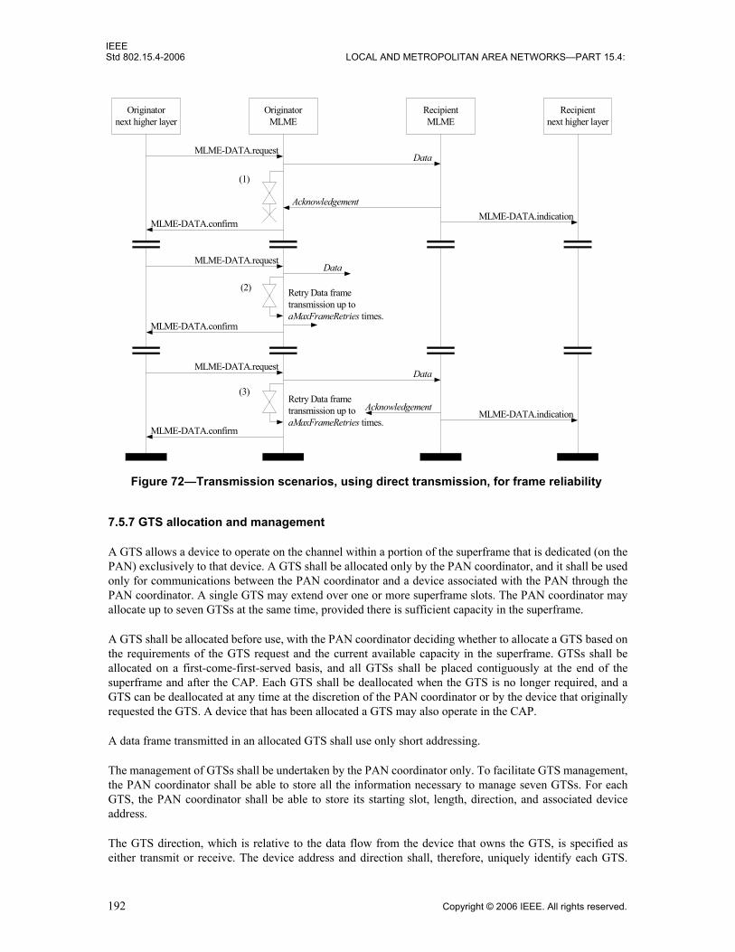
IEEEStd 802.15.4-2006 LOCAL AND METROPOLITAN AREA NETWORKS—PART 15.4:
7.5.7 GTS allocation and management
A GTS allows a device to operate on the channel within a portion of the superframe that is dedicated (on thePAN) exclusively to that device. A GTS shall be allocated only by the PAN coordinator, and it shall be usedonly for communications between the PAN coordinator and a device associated with the PAN through thePAN coordinator. A single GTS may extend over one or more superframe slots. The PAN coordinator mayallocate up to seven GTSs at the same time, provided there is sufficient capacity in the superframe.
A GTS shall be allocated before use, with the PAN coordinator deciding whether to allocate a GTS based onthe requirements of the GTS request and the current available capacity in the superframe. GTSs shall beallocated on a first-come-first-served basis, and all GTSs shall be placed contiguously at the end of thesuperframe and after the CAP. Each GTS shall be deallocated when the GTS is no longer required, and aGTS can be deallocated at any time at the discretion of the PAN coordinator or by the device that originallyrequested the GTS. A device that has been allocated a GTS may also operate in the CAP.
A data frame transmitted in an allocated GTS shall use only short addressing.
The management of GTSs shall be undertaken by the PAN coordinator only. To facilitate GTS management,the PAN coordinator shall be able to store all the information necessary to manage seven GTSs. For eachGTS, the PAN coordinator shall be able to store its starting slot, length, direction, and associated deviceaddress.
The GTS direction, which is relative to the data flow from the device that owns the GTS, is specified aseither transmit or receive. The device address and direction shall, therefore, uniquely identify each GTS.
Figure 72—Transmission scenarios, using direct transmission, for frame reliability
Originatornext higher layer
OriginatorMLME
MLME-DATA.request
MLME-DATA.indicationMLME-DATA.confirm
Recipientnext higher layer
RecipientMLME
Data
Acknowledgement
MLME-DATA.request
MLME-DATA.confirm
Data
Retry Data frametransmission up toaMaxFrameRetries times.
MLME-DATA.request
MLME-DATA.confirm
Retry Data frametransmission up toaMaxFrameRetries times.
MLME-DATA.indication
Data
Acknowledgement
(1)
(2)
(3)
192 Copyright © 2006 IEEE. All rights reserved.

IEEEWIRELESS MAC AND PHY SPECIFICATIONS FOR LR-WPANS Std 802.15.4-2006
Each device may request one transmit GTS and/or one receive GTS. For each allocated GTS, the deviceshall be able to store its starting slot, length, and direction. If a device has been allocated a receive GTS, itshall enable its receiver for the entirety of the GTS. In the same way, the PAN coordinator shall enable itsreceiver for the entirety of the GTS if a device has been allocated a transmit GTS. If a data frame is receivedduring a receive GTS and an acknowledgment is requested, the device shall transmit the acknowledgmentframe as usual. Similarly, a device shall be able to receive an acknowledgment frame during a transmit GTS.
A device shall attempt to allocate and use a GTS only if it is currently tracking the beacons. The MLME isinstructed to track beacons by issuing the MLME-SYNC.request primitive with the TrackBeacon parameterset to TRUE. If a device loses synchronization with the PAN coordinator, all its GTS allocations shall belost.
The use of GTSs is optional.
7.5.7.1 CAP maintenance
The PAN coordinator shall preserve the minimum CAP length of aMinCAPLength and take preventativeaction if the minimum CAP is not satisfied. However, an exception shall be allowed for the accommodationof the temporary increase in the beacon frame length needed to perform GTS maintenance. If preventativeaction becomes necessary, the action chosen is left up to the implementation, but may include one or more ofthe following:
— Limiting the number of pending addresses included in the beacon.— Not including a payload field in the beacon frame.— Deallocating one or more of the GTSs
7.5.7.2 GTS allocation
A device is instructed to request the allocation of a new GTS through the MLME-GTS.request primitive,with GTS characteristics set according to the requirements of the intended application.
To request the allocation of a new GTS, the MLME shall send the GTS request command (see 7.3.9) to thePAN coordinator. The Characteristics Type subfield of the GTS Characteristics field of the request shall beset to one (GTS allocation), and the length and direction subfields shall be set according to the desiredcharacteristics of the required GTS. Because the GTS request command contains an acknowledgmentrequest (see 7.3.3.1), the PAN coordinator shall confirm its receipt by sending an acknowledgment frame.
On receipt of a GTS request command indicating a GTS allocation request, the PAN coordinator shall firstcheck if there is available capacity in the current superframe, based on the remaining length of the CAP andthe desired length of the requested GTS. The superframe shall have available capacity if the maximumnumber of GTSs has not been reached and allocating a GTS of the desired length would not reduce thelength of the CAP to less than aMinCAPLength. GTSs shall be allocated on a first-come-first-served basisby the PAN coordinator provided there is sufficient bandwidth available. The PAN coordinator shall makethis decision within aGTSDescPersistenceTime superframes.
On receipt of the acknowledgment to the GTS request command, the device shall continue to track beaconsand wait for at most aGTSDescPersistenceTime superframes. If no GTS descriptor for the device appears inthe beacon within this time, the MLME of the device shall notify the next higher layer of the failure. Thisnotification is achieved when the MLME issues the MLME-GTS.confirm primitive (see 7.1.7.2) with astatus of NO_DATA.
When the PAN coordinator determines whether capacity is available for the requested GTS, it shall generatea GTS descriptor with the requested specifications and the 16-bit short address of the requesting device. Ifthe GTS was allocated successfully, the PAN coordinator shall set the start slot in the GTS descriptor to the
Copyright © 2006 IEEE. All rights reserved. 193

IEEEStd 802.15.4-2006 LOCAL AND METROPOLITAN AREA NETWORKS—PART 15.4:
superframe slot at which the GTS begins and the length in the GTS descriptor to the length of the GTS. Inaddition, the PAN coordinator shall notify the next higher layer of the new GTS. This notification isachieved when the MLME of the PAN coordinator issues the MLME-GTS.indication primitive (see 7.1.7.3)with the characteristics of the allocated GTS. If there was not sufficient capacity to allocate the requestedGTS, the start slot shall be set to zero and the length to the largest GTS length that can currently besupported. The PAN coordinator shall then include this GTS descriptor in its beacon and update the GTSSpecification field of the beacon frame accordingly. The PAN coordinator shall also update the Final CAPSlot subfield of the Superframe Specification field of the beacon frame, indicating the final superframe slotutilized by the decreased CAP. The GTS descriptor shall remain in the beacon frame foraGTSDescPersistenceTime superframes, after which it shall be removed automatically. The PANcoordinator shall be allowed to reduce its CAP below aMinCAPLength to accommodate the temporaryincrease in the beacon frame length due to the inclusion of the GTS descriptor.
On receipt of a beacon frame containing a GTS descriptor corresponding to macShortAddress, the deviceshall process the descriptor. The MLME of the device shall then notify the next higher layer of whether theGTS allocation request was successful. This notification is achieved when the MLME issues the MLME-GTS.confirm primitive with a status of SUCCESS (if the start slot in the GTS descriptor was greater thanzero) or DENIED (if the start slot was equal to zero or if the length did not match the requested length).
7.5.7.3 GTS usage
When the MAC sublayer of a device that is not the PAN coordinator receives an MCPS-DATA.requestprimitive (see 7.1.1.1) with the TxOptions parameter indicating a GTS transmission, it shall determinewhether it has a valid transmit GTS. If a valid GTS is found, the MAC sublayer shall transmit the dataduring the GTS, i.e., between its starting slot and its starting slot plus its length. At this time, the MACsublayer shall transmit the MPDU immediately without using CSMA-CA, provided the requestedtransaction can be completed before the end of the GTS. If the requested transaction cannot be completedbefore the end of the current GTS, the MAC sublayer shall defer the transmission until the specified GTS inthe next superframe. Note that the MAC must allow for the PHY overhead (see 6.7.2.2) in making thisdetermination.
If the device has any receive GTSs, the MAC sublayer of the device shall ensure that the receiver is enabledat a time prior to the start of the GTS and for the duration of the GTS, as indicated by its starting slot and itslength.
When the MAC sublayer of the PAN coordinator receives an MCPS-DATA.request primitive with theTxOptions parameter indicating a GTS transmission, it shall determine whether it has a valid receive GTScorresponding to the device with the requested destination address. If a valid GTS is found, the PANcoordinator shall defer the transmission until the start of the receive GTS. In this case, the address of thedevice with the message requiring a GTS transmission shall not be added to the list of pending addresses inthe beacon frame (see 7.5.5). At the start of the receive GTS, the MAC sublayer shall transmit the datawithout using CSMA-CA, provided the requested transaction can be completed before the end of the GTS. Ifthe requested transaction cannot be completed before the end of the current GTS, the MAC sublayer shalldefer the transmission until the specified GTS in the next superframe.
For all allocated transmit GTSs (relative to the device), the MAC sublayer of the PAN coordinator shallensure that its receiver is enabled at a time prior to the start and for the duration of each GTS.
Before commencing transmission in a GTS, each device shall ensure that the data transmission, theacknowledgment, if requested, and the IFS, suitable to the size of the data frame, can be completed beforethe end of the GTS.
194 Copyright © 2006 IEEE. All rights reserved.

IEEEWIRELESS MAC AND PHY SPECIFICATIONS FOR LR-WPANS Std 802.15.4-2006
If a device misses the beacon at the beginning of a superframe, it shall not use its GTSs until it receives asubsequent beacon correctly. If a loss of synchronization occurs due to the loss of the beacon, the deviceshall consider all of its GTSs deallocated.
7.5.7.4 GTS deallocation
A device is instructed to request the deallocation of an existing GTS through the MLME-GTS.requestprimitive (see 7.1.7.1), using the characteristics of the GTS it wishes to deallocate. From this point onward,the GTS to be deallocated shall not be used by the device, and its stored characteristics shall be reset.
To request the deallocation of an existing GTS, the MLME shall send the GTS request command (see 7.3.9)to the PAN coordinator. The Characteristics Type subfield of the GTS Characteristics field of the requestshall be set to zero (i.e., GTS deallocation), and the length and direction subfields shall be set according tothe characteristics of the GTS to deallocate. Because the GTS request command contains anacknowledgment request (see 7.3.3.1), the PAN coordinator shall confirm its receipt by sending anacknowledgment frame. On receipt of the acknowledgment to the GTS request command, the MLME shallnotify the next higher layer of the deallocation. This notification is achieved when the MLME issues theMLME-GTS.confirm primitive (see 7.1.7.2) with a status of SUCCESS and a GTSCharacteristics parameterwith its Characteristics Type subfield set to zero. If the GTS request command is not received correctly bythe PAN coordinator, it shall determine that the device has stopped using its GTS by the procedure describedin 7.5.7.6.
On receipt of a GTS request command with the Characteristics Type subfield of the GTS Characteristicsfield set to zero (GTS deallocation), the PAN coordinator shall attempt to deallocate the GTS. If the GTScharacteristics contained in the GTS request command do not match the characteristics of a known GTS, thePAN coordinator shall ignore the request. If the GTS characteristics contained in the GTS request commandmatch the characteristics of a known GTS, the MLME of the PAN coordinator shall deallocate the specifiedGTS and notify the next higher layer of the change. This notification is achieved when the MLME issues theMLME-GTS.indication primitive (see 7.1.7.3) with a GTSCharacteristics parameter containing thecharacteristics of the deallocated GTS and a Characteristics Type subfield set to zero. The PAN coordinatorshall also update the Final CAP Slot subfield of the Superframe Specification field of the beacon frame,indicating the final superframe slot utilized by the increased CAP. It shall not add a descriptor to the beaconframe to describe the deallocation.
GTS deallocation may be initiated by the PAN coordinator due to a deallocation request from the nexthigher layer, the expiration of the GTS (see 7.5.7.6), or maintenance required to maintain the minimum CAPlength, aMinCAPLength (see 7.5.7.1).
When a GTS deallocation is initiated by the next higher layer of the PAN coordinator, the MLME shallreceive the MLME-GTS.request primitive with the GTS Characteristics field of the request set to zero (i.e.,GTS deallocation) and the length and direction subfields set according to the characteristics of the GTS todeallocate.
When a GTS deallocation is initiated by the PAN coordinator either due to the GTS expiring or due to CAPmaintenance, the MLME shall notify the next higher layer of the change. This notification is achieved whenthe MLME issues the MLME-GTS.indication primitive with a GTSCharacteristics parameter containing thecharacteristics of the deallocated GTS and a Characteristics Type subfield set to zero.
In the case of any deallocation initiated by PAN coordinator, the PAN coordinator shall deallocate the GTSand add a GTS descriptor into its beacon frame corresponding to the deallocated GTS, but with its startingslot set to zero. The descriptor shall remain in the beacon frame for aGTSDescPersistenceTime superframes.The PAN coordinator shall be allowed to reduce its CAP below aMinCAPLength to accommodate thetemporary increase in the beacon frame length due to the inclusion of the GTS descriptor.
Copyright © 2006 IEEE. All rights reserved. 195

IEEEStd 802.15.4-2006 LOCAL AND METROPOLITAN AREA NETWORKS—PART 15.4:
On receipt of a beacon frame containing a GTS descriptor corresponding to macShortAddress and a start slotequal to zero, the device shall immediately stop using the GTS. The MLME of the device shall then notifythe next higher layer of the deallocation. This notification is achieved when the MLME issues the MLME-GTS.indication primitive with a GTSCharacteristics parameter containing the characteristics of thedeallocated GTS and a Characteristics Type subfield set to zero.
7.5.7.5 GTS reallocation
The deallocation of a GTS may result in the superframe becoming fragmented. For example, Figure 73shows three stages of a superframe with allocated GTSs. In stage 1, three GTSs are allocated starting at slots14, 10, and 8, respectively. If GTS 2 is now deallocated (stage 2), there will be a gap in the superframeduring which nothing can happen. To solve this, GTS 3 will have to be shifted to fill the gap, thus increasingthe size of the CAP (stage 3).
The PAN coordinator shall ensure that any gaps occurring in the CFP, appearing due to the deallocation of aGTS, are removed to maximize the length of the CAP.
When a GTS is deallocated by the PAN coordinator, it shall add a GTS descriptor into its beacon frameindicating that the GTS has been deallocated. If the deallocation is initiated by a device, the PANcoordinator shall not add a GTS descriptor into its beacon frame to indicate the deallocation. For each devicewith an allocated GTS having a starting slot lower than the GTS being deallocated, the PAN coordinatorshall update the GTS with the new starting slot and add a GTS descriptor to its beacon corresponding to thisadjusted GTS. The new starting slot is computed so that no space is left between this GTS and either the endof the CFP, if the GTS appears at the end of the CFP, or the start of the next GTS in the CFP.
Figure 73—CFP defragmentation on GTS deallocations
196 Copyright © 2006 IEEE. All rights reserved.
IEEEWIRELESS MAC AND PHY SPECIFICATIONS FOR LR-WPANS Std 802.15.4-2006
In situations where multiple reallocations occur at the same time, the PAN coordinator may choose toperform the reallocation in stages. The PAN coordinator shall keep each GTS descriptor in its beacon foraGTSDescPersistenceTime superframes.
On receipt of a beacon frame containing a GTS descriptor corresponding to macShortAddress and adirection and length corresponding to one of its GTSs, the device shall adjust the starting slot of the GTScorresponding to the GTS descriptor and start using it immediately.
In cases where it is necessary for the PAN coordinator to include a GTS descriptor in its beacon, it shall beallowed to reduce its CAP below aMinCAPLength to accommodate the temporary increase in the beaconframe length. After aGTSDescPersistenceTime superframes, the PAN coordinator shall remove the GTSdescriptor from the beacon.
7.5.7.6 GTS expiration
The MLME of the PAN coordinator shall attempt to detect when a device has stopped using a GTS using thefollowing rules:
— For a transmit GTS, the MLME of the PAN coordinator shall assume that a device is no longer usingits GTS if a data frame is not received from the device in the GTS at least every 2*n superframes,where n is defined below.
— For receive GTSs, the MLME of the PAN coordinator shall assume that a device is no longer usingits GTS if an acknowledgment frame is not received from the device at least every 2*n superframes,where n is defined below. If the data frames sent in the GTS do not require acknowledgment frames,the MLME of the PAN coordinator will not be able to detect whether a device is using its receiveGTS. However, the PAN coordinator is capable of deallocating the GTS at any time.
The value of n is defined as follows:
n = 2(8-macBeaconOrder) 0 ≤ macBeaconOrder ≤ 8
n = 1 9 ≤ macBeaconOrder ≤ 14
7.5.8 Frame security
The MAC sublayer is responsible for providing security services on specified incoming and outgoing frameswhen requested to do so by the higher layers. This standard supports the following security services (see5.5.6 for definitions):
— Data confidentiality— Data authenticity— Replay protection
The information determining how to provide the security is found in the security-related PIB (see Table 88in 7.6.1).
7.5.8.1 Security-related MAC PIB attributes
The security-related MAC PIB attributes contain:— Key table (macKeyTable, macKeyTableEntries)— Device table (macDeviceTable, macDeviceTableEntries)— Minimum security level table (macSecurityLevelTable, macSecurityLevelTableEntries) — Frame counter (macFrameCounter)
Copyright © 2006 IEEE. All rights reserved. 197
IEEEStd 802.15.4-2006 LOCAL AND METROPOLITAN AREA NETWORKS—PART 15.4:
— Automatic request attributes (macAutoRequestSecurityLevel, macAutoRequestKeyIdMode, macAu-toRequestKeySource, macAutoRequestKeyIndex)
— Default key source (macDefaultKeySource)— PAN coordinator address (macPANCoordExtendedAddress, macPANCoordShortAddress)
7.5.8.1.1 Key table
The key table holds key descriptors (keys with related key-specific information) that are required forsecurity processing of outgoing and incoming frames. Key-specific information in the key table is identifiedbased on information explicitly contained in the requesting primitive or in the received frame, as describedin the outgoing frame key retrieval procedure (see 7.5.8.2.2) and the incoming frame security materialretrieval procedure (see 7.5.8.2.4), as well as in the KeyDescriptor lookup procedure (see 7.5.8.2.5).
7.5.8.1.2 Device table
The device table holds device descriptors (device-specific addressing information and security-relatedinformation) that, when combined with key-specific information from the key table, provide all the keyingmaterial needed to secure outgoing (see 7.5.8.2.1) and unsecure incoming frames (see 7.5.8.2.3). Device-specific information in the device table is identified based on the originator of the frame, as described in theDeviceDescriptor lookup procedure (see 7.5.8.2.7), and on key-specific information, as described in theblacklist checking procedure (see 7.5.8.2.6).
7.5.8.1.3 Minimum security level table
The minimum security level table holds information regarding the minimum security level the deviceexpects to have been applied by the originator of a frame, depending on frame type and, if it concerns aMAC command frame, the command frame identifier. Security processing of an incoming frame will fail ifthe frame is not adequately protected, as described in the incoming frame security procedure (see 7.5.8.2.3)and in the incoming security level checking procedure (see 7.5.8.2.8).
7.5.8.1.4 Frame counter
The 4-octet frame counter is used to provide replay protection and semantic security of the cryptographicbuilding block used for securing outgoing frames. The frame counter is included in each secured frame andis one of the elements required for the unsecuring operation at the recipient(s). The frame counter isincremented each time an outgoing frame is secured, as described in the outgoing frame security procedure(see 7.5.8.2.1). When the frame counter reaches its maximum value of 0xffffffff, the associated keyingmaterial can no longer be used, thus requiring all keys associated with the device to be updated. Thisprovides a mechanism for ensuring that the keying material for every frame is unique and, thereby, providesfor sequential freshness.
7.5.8.1.5 Automatic request attributes
Automatic request attributes hold all the information needed to secure outgoing frames generatedautomatically and not as a result of a higher layer primitive, as is the case with automatic data requests.
7.5.8.1.6 Default key source
The default key source is information commonly shared between originator and receipient(s) of a securedframe, which, when combined with additional information explicitly contained in the requesting primitive orin the received frame, allows an originator or a recipient to determine the key required for securing orunsecuring this frame, respectively. This provides a mechanism for significantly reducing the overhead ofsecurity information contained in secured frames in particular use cases (see 7.5.8.2.2 and 7.5.8.2.4).
198 Copyright © 2006 IEEE. All rights reserved.

IEEEWIRELESS MAC AND PHY SPECIFICATIONS FOR LR-WPANS Std 802.15.4-2006
7.5.8.1.7 PAN coordinator address
The address of the PAN coordinator is information commonly shared between all devices in a PAN, which,when combined with additional information explicitly contained in the requesting primitive or in thereceived frame, allows an originator of a frame directed to the PAN coordinator or a recipient of a frameoriginating from the PAN coordinator to determine the key and security-related information required forsecuring or unsecuring, respectively, this frame (see 7.5.8.2.2 and 7.5.8.2.4).
7.5.8.2 Functional description
A device may optionally implement security. A device that does not implement security shall not provide amechanism for the MAC sublayer to perform any cryptographic transformation on incoming and outgoingframes nor require any PIB attributes associated with security. A device that implements security shallprovide a mechanism for the MAC sublayer to provide cryptographic transformations on incoming andoutgoing frames using information in the PIB attributes associated with security when themacSecurityEnabled attribute is set to TRUE.
If the MAC sublayer is required to transmit a frame or receives an incoming frame, the MAC sublayer shallprocess the frame as specified in 7.5.8.2.1 and 7.5.8.2.3, respectively.
7.5.8.2.1 Outgoing frame security procedure
The inputs to this procedure are the frame to be secured and the SecurityLevel, KeyIdMode, KeySource, andKeyIndex parameters from the originating primitive or automatic request PIB attributes. The outputs fromthis procedure are the status of the procedure and, if this status is SUCCESS, the secured frame.
The outgoing frame security procedure involves the following steps as applicable:a) If the Security Enabled subfield of the Frame Control field of the frame to be secured is set to zero,
the procedure shall set the security level to zero.b) If the Security Enabled subfield of the Frame Control field of the frame to be secured is set to one,
the procedure shall set the security level to the SecurityLevel parameter. If the resulting securitylevel is zero, the procedure shall return with a status of UNSUPPORTED_SECURITY.
c) If the macSecurityEnabled attribute is set to FALSE and the security level is not equal to zero, theprocedure shall return with a status of UNSUPPORTED_SECURITY.
d) The procedure shall determine whether the frame to be secured satisfies the constraint on themaximum length of MAC frames, as follows:1) The procedure shall set the length M, in octets, of the Authentication field to zero if the security
level is equal to zero and shall determine this value from the security level and Table 95otherwise.
2) The procedure shall determine the length AuxLen, in octets, of the auxiliary security header(see 7.6.2) using KeyIdMode and the security level.
3) The procedure shall determine the data expansion as AuxLen + M.4) The procedure shall check whether the length of the frame to be secured, including data
expansion and FCS, is less than or equal to aMaxPHYPacketSize. If this check fails, theprocedure shall return with a status of FRAME_TOO_LONG.
e) If the security level is zero, the procedure shall set the secured frame to be the frame to be securedand return with the secured frame and a status of SUCCESS.
f) The procedure shall set the frame counter to the macFrameCounter attribute. If the frame counterhas the value 0xffffffff, the procedure shall return with a status of COUNTER_ERROR.
g) The procedure shall obtain the key using the outgoing frame key retrieval procedure as described in7.5.8.2.2. If that procedure fails, the procedure shall return with a status of UNAVAILABLE_KEY.
Copyright © 2006 IEEE. All rights reserved. 199

IEEEStd 802.15.4-2006 LOCAL AND METROPOLITAN AREA NETWORKS—PART 15.4:
h) The procedure shall insert the auxiliary security header into the frame, with fields set as follows:1) The Security Level subfield of the Security Control field shall be set to the security level.2) The Key Identifier Mode subfield of the Security Control field shall be set to the KeyIdMode
parameter.3) The Frame Counter field shall be set to the frame counter.4) If the KeyIdMode parameter is set to a value not equal to zero, the Key Source and Key Index
subfields of the Key Identifier field shall be set to the KeySource and KeyIndex parameters,respectively.
i) The procedure shall then use aExtendedAddress, the frame counter, the security level, and the key toproduce the secured frame according to the transformation process known as CCM* [or theextension of CCM, which is the combined counter with CBC-MAC (i.e., cipher block chainingmessage authentication code) mode of operation] that is described in the security operations (see7.6.3.4).1) If the SecurityLevel parameter specifies the use of encryption (see Table 95 in 7.6.2.2.1), the
encryption operation shall be applied only to the actual payload field within the MAC payload,i.e., the Beacon Payload field (see 7.2.2.1.8), Command Payload field (see 7.2.2.4.3), or DataPayload field (see 7.2.2.2.2), depending on the frame type. The corresponding payload field ispassed to the CCM* transformation process described in 7.6.3.4 as the unsecured payload (seeTable 97 in 7.6.3.4.2). The resulting encrypted payload shall substitute the original payload.
2) The remaining fields in the MAC payload part of the frame shall be passed to the CCM*transformation process described in 7.6.3.4 as the nonpayload fields (see Table 97).
3) The ordering and exact manner of performing the encryption and integrity operations and theplacement of the resulting encrypted data or integrity code within the MAC Payload field shallbe as defined in 7.6.3.4.
j) The procedure shall increment the frame counter by one and set the macFrameCounter attribute tothe resulting value.
k) The procedure shall return with the secured frame and a status of SUCCESS.
7.5.8.2.2 Outgoing frame key retrieval procedure
The inputs to this procedure are the frame to be secured and the KeyIdMode, KeySource, and KeyIndexparameters from the originating primitive. The outputs from this procedure are a passed or failed status and,if passed, a key.
The outgoing frame key retrieval procedure involves the following steps as applicable:a) If the KeyIdMode parameter is set to 0x00 (implicit key identification), the procedure shall
determine the key lookup data and key lookup size as follows:1) If the Destination Addressing Mode subfield of the Frame Control field of the frame is set to
0x00 and the macPANCoordShortAddress attribute is set to a value in the range 0x0000–0xfffd(i.e., the short address is used), the key lookup data shall be set to the 2-octet Source PANIdentifier field of the frame right-concatenated (see B.2.1) with the 2-octetmacPANCoordShortAddress attribute right-concatenated with the single octet 0x00. The keylookup size shall be set to five.
2) If the Destination Addressing Mode subfield of the Frame Control field of the frame is set to0x00 and the macPANCoordShortAddress attribute is set to 0xfffe (i.e., the extended address isused), the key lookup data shall be set to the 8-octet macPANCoordExtendedAddress attributeright-concatenated (see B.2.1) with the single octet 0x00. The key lookup size shall be set tonine.
3) If the Destination Addressing Mode subfield of the Frame Control field of the frame is set to0x02, the key lookup data shall be set to the 2-octet Destination PAN Identifier field of the
200 Copyright © 2006 IEEE. All rights reserved.

IEEEWIRELESS MAC AND PHY SPECIFICATIONS FOR LR-WPANS Std 802.15.4-2006
frame right-concatenated (see B.2.1) with the 2-octet Destination Address field of the frameright-concatenated with the single octet 0x00. The key lookup size shall be set to five.
4) If the Destination Addressing Mode subfield of the Frame Control field of the frame is set to0x03, the key lookup data shall be set to the 8-octet Destination Address field of the frameright-concatenated (see B.2.1) with the single octet 0x00. The key lookup size shall be set tonine.
b) If the KeyIdMode parameter is set to a value not equal to 0x00 (explicit key identification), theprocedure shall determine the key lookup data and key lookup size as follows:1) If the KeyIdMode parameter is set to 0x01, the key lookup data shall be set to the 8-octet
macDefaultKeySource attribute right-concatenated (see B.2.1) with the single octet KeyIndexparameter. The key lookup size shall be set to nine.
2) If the KeyIdMode parameter is set to 0x02, the key lookup data shall be set to the 4-octetKeySource parameter right-concatenated (see B.2.1) with the single octet KeyIndex parameter.The key lookup size shall be set to five.
3) If the KeyIdMode parameter is set to 0x03, the key lookup data shall be set to the 8-octetKeySource parameter right-concatenated (see B.2.1) with the single octet KeyIndex parameter.The key lookup size shall be set to nine.
c) The procedure shall obtain the KeyDescriptor by passing the key lookup data and the key lookupsize to the KeyDescriptor lookup procedure as described in 7.5.8.2.5. If that procedure returns with afailed status, this procedure shall also return with a failed status.
d) The MAC sublayer shall set the key to the Key element of the KeyDescriptor. e) The procedure shall return with a passed status, having obtained the key identifier and the key.
NOTE—For broadcast frames, the outgoing frame key retrieval procedure will result in a failed status if implicit keyidentification is used. Hence, explicit key identification should be used for broadcast frames.7
7.5.8.2.3 Incoming frame security procedure
The input to this procedure is the frame to be unsecured. The outputs from this procedure are the unsecuredframe, the security level, the key identifier mode, the key source, the key index, and the status of theprocedure. All outputs of this procedure are assumed to be invalid unless and until explicitly set in thisprocedure. It is assumed that the PIB attributes associating KeyDescriptors in macKeyTable with a single,unique device or a number of devices will have been established by the next higher layer.
The incoming frame security procedure involves the following steps as applicable:a) If the Security Enabled subfield of the Frame Control field of the frame to be unsecured is set to
zero, the procedure shall set the security level to zero.b) If the Security Enabled subfield of the Frame Control field of the frame to be unsecured is set to one
and the Frame Version subfield of the Frame Control field of the frame to be unsecured is set tozero, the procedure shall set the unsecured frame to be the frame to be unsecured and return with theunsecured frame, the security level, the key identifier mode, the key source, the key index, and astatus of UNSUPPORTED_LEGACY.
c) If the Security Enabled subfield of the Frame Control field of the frame to be unsecured is set to one,the procedure shall set the security level and the key identifier mode to the corresponding subfieldsof the Security Control field of the auxiliary security header of the frame to be unsecured and shallset the key source and key index to the corresponding subfields of the Key Identifier field of theauxiliary security header of the frame to be unsecured, if present. If the resulting security level iszero, the procedure shall set the unsecured frame to be the frame to be unsecured and return with theunsecured frame, the security level, the key identifier mode, the key source, the key index, and astatus of UNSUPPORTED_SECURITY.
7Notes in text, tables, and figures are given for information only and do not contain requirements needed to implement the standard.
Copyright © 2006 IEEE. All rights reserved. 201

IEEEStd 802.15.4-2006 LOCAL AND METROPOLITAN AREA NETWORKS—PART 15.4:
d) If the macSecurityEnabled attribute is set to FALSE, the procedure shall set the unsecured frame tobe the frame to be unsecured and return with the unsecured frame, the security level, the keyidentifier mode, the key source, the key index, and a status of SUCCESS if the security level is equalto zero and with the unsecured frame, the security level, the key identifier mode, the key source, thekey index, and a status of UNSUPPORTED_SECURITY otherwise.
e) The procedure shall determine whether the frame to be unsecured meets the minimum security levelby passing the security level, the frame type, and, depending on whether the frame is a MACcommand frame, the first octet of the MAC payload (i.e., command frame identifier for a MACcommand frame) to the incoming security level checking procedure as described in 7.5.8.2.8. If thatprocedure fails, the procedure shall set the unsecured frame to be the frame to be unsecured andreturn with the unsecured frame, the security level, the key identifier mode, the key source, the keyindex, and a status of IMPROPER_SECURITY_LEVEL.
f) If the security level is set to zero, the procedure shall set the unsecured frame to be the frame to beunsecured and return with the unsecured frame, the security level, the key identifier mode, the keysource, the key index, and a status of SUCCESS.
g) The procedure shall obtain the KeyDescriptor, DeviceDescriptor, and KeyDeviceDescriptor usingthe incoming frame security material retrieval procedure described in 7.5.8.2.4. If that procedurefails, the procedure shall set the unsecured frame to be the frame to be unsecured and return with theunsecured frame, the security level, the key identifier mode, the key source, the key index, and astatus of UNAVAILABLE_KEY.
h) The procedure shall determine whether the frame to be unsecured conforms to the key usage policyby passing the KeyDescriptor, the frame type, and, depending on whether the frame is a MACcommand frame, the first octet of the MAC payload (i.e., command frame identifier for a MACcommand frame) to the incoming key usage policy checking procedure as described in 7.5.8.2.9. Ifthat procedure fails, the procedure shall set the unsecured frame to be the frame to be unsecured andreturn with the unsecured frame, the security level, the key identifier mode, the key source, the keyindex, and a status of IMPROPER_KEY_TYPE.
i) If the Exempt element of the DeviceDescriptor is set to FALSE and if the incoming security levelchecking procedure of Step e above had as output the “conditionally passed” status, the procedureshall set the unsecured frame to be the frame to be unsecured and return with the unsecured frame,the security level, the key identifier mode, the key source, the key index, and a status ofIMPROPER_SECURITY_LEVEL.
j) The procedure shall set the frame counter to the Frame Counter field of the auxiliary security headerof the frame to be unsecured. If the frame counter has the value 0xffffffff, the procedure shall set theunsecured frame to be the frame to be unsecured and return with the unsecured frame, the securitylevel, the key identifier mode, the key source, the key index, and a status of COUNTER_ERROR.
k) The procedure shall determine whether the frame counter is greater than or equal to theFrameCounter element of the DeviceDescriptor. If this check fails, the procedure shall set theunsecured frame to be the frame to be unsecured and return with the unsecured frame, the securitylevel, the key identifier mode, the key source, the key index, and a status of COUNTER_ERROR.
l) The procedure shall then use the ExtAddress element of the DeviceDescriptor, the frame counter,the security level, and the Key element of the KeyDescriptor to produce the unsecured frameaccording to the CCM* inverse transformation process described in the security operations (see7.6.3.5).1) If the security level specifies the use of encryption (see Table 95 in 7.6.2.2.1), the decryption
operation shall be applied only to the actual payload field within the MAC payload, i.e., theBeacon Payload field (see 7.2.2.1.8), Command Payload field (see 7.2.2.4.3), or Data Payloadfield (see 7.2.2.2.2), depending on the frame type. The corresponding payload field shall bepassed to the CCM* inverse transformation process described in 7.6.3.5 as the secure payload.
2) The remaining fields in the MAC payload part of the frame shall be passed to the CCM*inverse transformation process described in 7.6.3.5 as the nonpayload fields.
202 Copyright © 2006 IEEE. All rights reserved.

IEEEWIRELESS MAC AND PHY SPECIFICATIONS FOR LR-WPANS Std 802.15.4-2006
m) If the CCM* inverse transformation process fails, the procedure shall set the unsecured frame to bethe frame to be unsecured and return with the unsecured frame, the security level, the key identifiermode, the key source, the key index, and a status of SECURITY_ERROR.
n) The procedure shall increment the frame counter by one and set the FrameCounter element of theDeviceDescriptor to the resulting value.
o) If the FrameCounter element is equal to 0xffffffff, the procedure shall set the Blacklisted element ofthe KeyDeviceDescriptor.
p) The procedure shall return with the unsecured frame, the security level, the key identifier mode, thekey source, the key index, and a status of SUCCESS.
7.5.8.2.4 Incoming frame security material retrieval procedure
The input to this procedure is the frame to be unsecured. The outputs from this procedure are a passed orfailed status and, if passed, a KeyDescriptor, a DeviceDescriptor, and a KeyDeviceDescriptor.
The incoming frame security material retrieval procedure involves the following steps as applicable:a) If the Key Identifier Mode subfield of the Security Control field of the auxiliary security header of
the frame is set to 0x00 (implicit key identification), the procedure shall determine the key lookupdata and the key lookup size as follows:1) If the source address mode of the Frame Control field of the frame is set to 0x00 and the
macPANCoordShortAddress attribute is set to a value in the range 0x0000–0xfffd (i.e., theshort address is used), the key lookup data shall be set to the 2-octet Destination PAN Identifierfield of the frame right-concatenated (see B.2.1) with the 2-octet macPANCoordShortAddressattribute right-concatenated with the single octet 0x00. The key lookup size shall be set to five.
2) If the source address mode of the Frame Control field of the frame is set to 0x00 and themacPANCoordShortAddress attribute is set to 0xfffe (i.e., the extended address is used), thekey lookup data shall be set to the 8-octet macPANCoordExtendedAddress attribute right-concatenated (see B.2.1) with the single octet 0x00. The key lookup size shall be set to nine.
3) If the source address mode of the Frame Control field of the frame is set to 0x02, the keylookup data shall be set to the 2-octet Source PAN Identifier field of the frame, or to the 2-octetDestination PAN Identifier field of the frame if the PAN ID Compression subfield of the FrameControl field of the frame is set to one, right-concatenated (see B.2.1) with the 2-octet SourceAddress field of the frame right-concatenated with the single octet 0x00. The key lookup sizeshall be set to five.
4) If the source address mode of the Frame Control field of the frame is set to 0x03, the keylookup data shall be set to the 8-octet Source Address field of the frame right-concatenated (seeB.2.1) with the single octet 0x00. The key lookup size shall be set to nine.
b) If the Key Identifier Mode subfield of the Security Control field of the auxiliary security header ofthe frame is set to a value not equal to 0x00 (explicit key identification), the procedure shalldetermine the key lookup data and key lookup size as follows:1) If the key identifier mode is set to 0x01, the key lookup data shall be set to the 8-octet
macDefaultKeySource attribute right-concatenated (see B.2.1) with the 1-octet Key Indexsubfield of the Key Identifier field of the auxiliary security header. The key lookup size shall beset to nine.
2) If the key identifier mode is set to 0x02, the key lookup data shall be set to the right-concatenation (see B.2.1) of the 4-octet Key Source subfield and the 1-octet Key Index subfieldof the Key Identifier field of the auxiliary security header. The key lookup size shall be set tofive.
3) If the key identifier mode is set to 0x03, the key lookup data shall be set to the right-concatenation (see B.2.1) of the 8-octet Key Source subfield and the 1-octet Key Index subfield
Copyright © 2006 IEEE. All rights reserved. 203

IEEEStd 802.15.4-2006 LOCAL AND METROPOLITAN AREA NETWORKS—PART 15.4:
of the Key Identifier field of the auxiliary security header. The key lookup size shall be set tonine.
c) The procedure shall obtain the KeyDescriptor by passing the key lookup data and the key lookupsize to the KeyDescriptor lookup procedure as described in 7.5.8.2.5. If that procedure returns with afailed status, the procedure shall also return with a failed status.
d) The procedure shall determine the device lookup data and the device lookup size as follows:1) If the source address mode of the Frame Control field of the frame is set to 0x00 and the
macPANCoordShortAddress attribute is set to a value in the range 0x0000–0xfffd (i.e., theshort address is used), the device lookup data shall be set to the 2-octet Destination PANIdentifier field of the frame right-concatenated (see B.2.1) with the 2-octetmacPANCoordShortAddress attribute. The device lookup size shall be set to four.
2) If the source address mode of the Frame Control field of the frame is set to 0x00 and themacPANCoordShortAddress attribute is set to 0xfffe (i.e., the extended address is used), thedevice lookup data shall be set to the 8-octet macPANCoordExtendedAddress attribute. Thedevice lookup size shall be set to eight.
3) If the source address mode of the Frame Control field of the frame is set to 0x02, the devicelookup data shall be set to the 2-octet Source PAN Identifier field of the frame, or to the 2-octetDestination PAN Identifier field of the frame if the PAN ID Compression subfield of the FrameControl field of the frame is set to one, right-concatenated (see B.2.1) with the 2-octet SourceAddress field of the frame. The device lookup size shall be set to four.
4) If the source address mode of the Frame Control field of the frame is set to 0x03, the devicelookup data shall be set to the 8-octet Source Address field of the frame. The device lookup sizeshall be set to eight.
e) The procedure shall obtain the DeviceDescriptor and the KeyDeviceDescriptor by passing theKeyDescriptor, the device lookup data, and the device lookup size to the blacklist checkingprocedure as described in 7.5.8.2.6. If that procedure returns with a failed status, the procedure shallalso return with a failed status.
f) The procedure shall return with a passed status having obtained the KeyDescriptor, theDeviceDescriptor, and the KeyDeviceDescriptor.
7.5.8.2.5 KeyDescriptor lookup procedure
The inputs to this procedure are the key lookup data and the key lookup size. The outputs from thisprocedure are a passed or failed status and, if passed, a KeyDescriptor.
The KeyDescriptor lookup procedure involves the following steps as applicable:a) For each KeyDescriptor in the macKeyTable attribute and for each KeyIdLookupDescriptor in the
KeyIdLookupList of the KeyDescriptor, the procedure shall check whether the LookupDataSizeelement of the KeyIdLookupDescriptor indicates the same integer value (see Figure 94) as the keylookup size and whether the LookupData element of the KeyIdLookupDescriptor is equal to the keylookup data. If both checks pass (i.e., there is a match), the procedure shall return with this(matching) KeyDescriptor and a passed status.
b) The procedure shall return with a failed status.
7.5.8.2.6 Blacklist checking procedure
The inputs to this procedure are the KeyDescriptor, the device lookup data, and the device lookup size. Theoutputs from this procedure are a passed or failed status and, if passed, a DeviceDescriptor and aKeyDeviceDescriptor.
The blacklist checking procedure involves the following steps as applicable:
204 Copyright © 2006 IEEE. All rights reserved.

IEEEWIRELESS MAC AND PHY SPECIFICATIONS FOR LR-WPANS Std 802.15.4-2006
a) For each KeyDeviceDescriptor in the KeyDeviceList of the KeyDescriptor: 1) The procedure shall obtain the DeviceDescriptor using the DeviceDescriptorHandle element of
the KeyDeviceDescriptor.2) If the UniqueDevice element of the KeyDeviceDescriptor is set to TRUE, the procedure shall
return with the DeviceDescriptor, the KeyDeviceDescriptor, and a passed status if theBlackListed element of the KeyDeviceDescriptor is set to FALSE, or the procedure shall returnwith a failed status if this Blacklisted element is set to TRUE.
3) If the UniqueDevice element of the KeyDeviceDescriptor is set to FALSE, the procedure shallexecute the DeviceDescriptor lookup procedure as described in 7.5.8.2.7, with the devicelookup data and the device lookup size as inputs. If the corresponding output of that procedureis a passed status, the procedure shall return with the DeviceDescriptor, the KeyDevice-Descriptor, and a passed status if the Blacklisted element of the KeyDeviceDescriptor is set toFALSE, or the procedure shall return with a failed status if this Blacklisted element is set to TRUE.
b) The procedure shall return with a failed status.
7.5.8.2.7 DeviceDescriptor lookup procedure
The inputs to this procedure are the DeviceDescriptor, the device lookup data, and the device lookup size.The output from this procedure is a passed or failed status.
The DeviceDescriptor lookup procedure involves the following steps as applicable:a) If the device lookup size is four and the device lookup data is equal to the PAN ID element of the
DeviceDescriptor right-concatenated (see B.2.1) with the ShortAddress element of the Device-Descriptor, this procedure shall return with a passed status.
b) If the device lookup size is eight and the device lookup data is equal to the ExtAddress element ofthe DeviceDescriptor, this procedure shall return with a passed status.
c) The procedure shall return with a failed status.
7.5.8.2.8 Incoming security level checking procedure
The inputs to this procedure are the incoming security level, the frame type and the command frameidentifier. The output from this procedure is a passed, failed, or “conditionally passed” status.
The incoming security level checking procedure involves the following steps as applicable:a) For each SecurityLevelDescriptor in the macSecurityLevelTable attribute:
1) If the frame type is not equal to 0x03 and the frame type is equal to the FrameType element ofthe SecurityLevelDescriptor, the procedure shall compare the incoming security level (asSEC1) with the SecurityMinimum element of the SecurityLevelDescriptor (as SEC2)according to the algorithm described in 7.6.2.2.1. If this comparison fails (i.e., evaluates toFALSE), the procedure shall return with a “conditionally passed” status if theDeviceOverrideSecurityMinimum element of the SecurityLevelDescriptor is set to TRUE andthe security level is set to zero and with a failed status otherwise.
2) If the frame type is equal to 0x03, the frame type is equal to the FrameType element of theSecurityLevelDescriptor, and the command frame identifier is equal to the CommandFrame-Identifier element of the SecurityLevelDescriptor, the procedure shall compare the incomingsecurity level (as SEC1) with the SecurityMinimum element of the SecurityLevelDescriptor (asSEC2) according to the algorithm described in 7.6.2.2.1. If this comparison fails (i.e., evaluatesto FALSE), the procedure shall return with a “conditionally passed” status if theDeviceOverrideSecurityMinimum element of the SecurityLevelDescriptor is set to TRUE andthe security level is set to zero and with a failed status otherwise.
b) The procedure shall return with a passed status.
Copyright © 2006 IEEE. All rights reserved. 205

IEEEStd 802.15.4-2006 LOCAL AND METROPOLITAN AREA NETWORKS—PART 15.4:
7.5.8.2.9 Incoming key usage policy checking procedure
The inputs to this procedure are the KeyDescriptor, the frame type, and the command frame identifier. Theoutput from this procedure is a passed or failed status.
The incoming key usage policy checking procedure involves the following steps as applicable:
a) For each KeyUsageDescriptor in the KeyUsageList of the KeyDescriptor:
1) If the frame type is not equal to 0x03 and the frame type is equal to the FrameType element ofthe KeyUsageDescriptor, the procedure shall return with a passed status.
2) If the frame type is equal to 0x03, the frame type is equal to the FrameType element of theKeyUsageDescriptor, and the command frame identifier is equal to the CommandFrame-Identifier element of the KeyUsageDescriptor, the procedure shall return with a passed status.
b) The procedure shall return with a failed status.
7.6 Security suite specifications
7.6.1 PIB security material
The PIB security-related attributes are presented in Table 88, Table 89, Table 90, Table 91, Table 92,Table 93, and Table 94.
Table 88— Security-related MAC PIB attributes
Attribute Identifier Type Range Description Default
macKeyTable 0x71 List of Key-Descriptor entries (see Table 89)
— A table of KeyDescriptor entries, each containing keys and related information required for secured communications.
(empty)
macKeyTableEntries 0x72 Integer Implementa-tion specific
The number of entries in macKeyTable.
0
macDeviceTable 0x73 List of Device-Descriptor entries (see Table 93)
— A table of Device-Descriptor entries, each indicating a remote device with which this device securely communicates.
(empty)
macDeviceTable-Entries
0x74 Integer Implementa-tion specific
The number of entries in macDeviceTable.
0
macSecurity-LevelTable
0x75 Table of SecurityLevelDescriptor entries (see Table 92)
— A table of SecurityLevel-Descriptor entries, each with information about the minimum security level expected depending on incoming frame type and subtype.
(empty)
macSecurity-LevelTableEntries
0x76 Integer Implementa-tion specific
The number of entries in macSecurityLevelTable.
0
macFrameCounter 0x77 Integer 0x00000000–0xffffffff
The outgoing frame counter for this device.
0x00000000
206 Copyright © 2006 IEEE. All rights reserved.
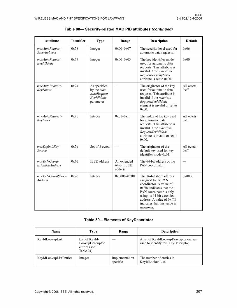
IEEEWIRELESS MAC AND PHY SPECIFICATIONS FOR LR-WPANS Std 802.15.4-2006
macAutoRequest-SecurityLevel
0x78 Integer 0x00–0x07 The security level used for automatic data requests.
0x06
macAutoRequest-KeyIdMode
0x79 Integer 0x00–0x03 The key identifier mode used for automatic data requests. This attribute is invalid if the macAuto-RequestSecurityLevel attribute is set to 0x00.
0x00
macAutoRequest-KeySource
0x7a As specified by the mac-AutoRequest-KeyIdMode parameter
— The originator of the key used for automatic data requests. This attribute is invalid if the macAuto-RequestKeyIdMode element is invalid or set to 0x00.
All octets 0xff
macAutoRequest-KeyIndex
0x7b Integer 0x01–0xff The index of the key used for automatic data requests. This attribute is invalid if the macAuto-RequestKeyIdMode attribute is invalid or set to 0x00.
All octets 0xff
macDefaultKey-Source
0x7c Set of 8 octets — The originator of the default key used for key identifier mode 0x01.
All octets 0xff
macPANCoord-ExtendedAddress
0x7d IEEE address An extended 64-bit IEEE address
The 64-bit address of the PAN coordinator.
—
macPANCoordShort-Address
0x7e Integer 0x0000–0xffff The 16-bit short address assigned to the PAN coordinator. A value of0xfffe indicates that the PAN coordinator is only using its 64-bit extended address. A value of 0xffff indicates that this value is unknown.
0x0000
Table 89—Elements of KeyDescriptor
Name Type Range Description
KeyIdLookupList List of KeyId-LookupDescriptor entries (see Table 94)
— A list of KeyIdLookupDescriptor entries used to identify this KeyDescriptor.
KeyIdLookupListEntries Integer Implementation specific
The number of entries in KeyIdLookupList.
Table 88— Security-related MAC PIB attributes (continued)
Attribute Identifier Type Range Description Default
Copyright © 2006 IEEE. All rights reserved. 207
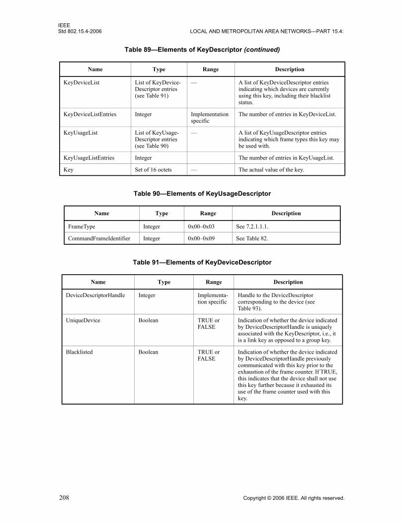
IEEEStd 802.15.4-2006 LOCAL AND METROPOLITAN AREA NETWORKS—PART 15.4:
KeyDeviceList List of KeyDevice-Descriptor entries (see Table 91)
— A list of KeyDeviceDescriptor entries indicating which devices are currently using this key, including their blacklist status.
KeyDeviceListEntries Integer Implementation specific
The number of entries in KeyDeviceList.
KeyUsageList List of KeyUsage-Descriptor entries (see Table 90)
— A list of KeyUsageDescriptor entries indicating which frame types this key may be used with.
KeyUsageListEntries Integer The number of entries in KeyUsageList.
Key Set of 16 octets — The actual value of the key.
Table 90—Elements of KeyUsageDescriptor
Name Type Range Description
FrameType Integer 0x00–0x03 See 7.2.1.1.1.
CommandFrameIdentifier Integer 0x00–0x09 See Table 82.
Table 91—Elements of KeyDeviceDescriptor
Name Type Range Description
DeviceDescriptorHandle Integer Implementa-tion specific
Handle to the DeviceDescriptor corresponding to the device (see Table 93).
UniqueDevice Boolean TRUE or FALSE
Indication of whether the device indicated by DeviceDescriptorHandle is uniquely associated with the KeyDescriptor, i.e., it is a link key as opposed to a group key.
Blacklisted Boolean TRUE or FALSE
Indication of whether the device indicated by DeviceDescriptorHandle previously communicated with this key prior to the exhaustion of the frame counter. If TRUE, this indicates that the device shall not use this key further because it exhausted its use of the frame counter used with this key.
Table 89—Elements of KeyDescriptor (continued)
Name Type Range Description
208 Copyright © 2006 IEEE. All rights reserved.
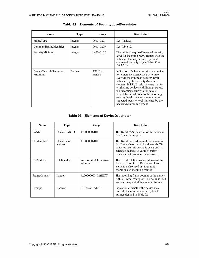
IEEEWIRELESS MAC AND PHY SPECIFICATIONS FOR LR-WPANS Std 802.15.4-2006
Table 92—Elements of SecurityLevelDescriptor
Name Type Range Description
FrameType Integer 0x00–0x03 See 7.2.1.1.1.
CommandFrameIdentifier Integer 0x00–0x09 See Table 82.
SecurityMinimum Integer 0x00–0x07 The minimal required/expected security level for incoming MAC frames with the indicated frame type and, if present, command frame type (see Table 95 in 7.6.2.2.1).
DeviceOverrideSecurity-Minimum
Boolean TRUE or FALSE
Indication of whether originating devices for which the Exempt flag is set may override the minimum security level indicated by the SecurityMinimum element. If TRUE, this indicates that for originating devices with Exempt status, the incoming security level zero is acceptable, in addition to the incoming security levels meeting the minimum expected security level indicated by the SecurityMinimum element.
Table 93—Elements of DeviceDescriptor
Name Type Range Description
PANId Device PAN ID 0x0000–0xffff The 16-bit PAN identifier of the device in this DeviceDescriptor.
ShortAddress Device short address
0x0000–0xffff The 16-bit short address of the device in this DeviceDescriptor. A value of 0xfffe indicates that this device is using only its extended address. A value of 0xffff indicates that this value is unknown.
ExtAddress IEEE address Any valid 64-bit device address
The 64-bit IEEE extended address of the device in this DeviceDescriptor. This element is also used in unsecuring operations on incoming frames.
FrameCounter Integer 0x00000000–0xffffffff The incoming frame counter of the device in this DeviceDescriptor. This value is used to ensure sequential freshness of frames.
Exempt Boolean TRUE or FALSE Indication of whether the device may override the minimum security level settings defined in Table 92.
Copyright © 2006 IEEE. All rights reserved. 209

IEEEStd 802.15.4-2006 LOCAL AND METROPOLITAN AREA NETWORKS—PART 15.4:
7.6.2 Auxiliary security header
The Auxiliary Security Header field has a variable length and contains information required for securityprocessing, including a Security Control field, a Frame Counter field, and a Key Identifier field. TheAuxiliary Security Header field shall be present only if the Security Enabled subfield of the Frame Controlfield is set to one. The Auxiliary Security Header field shall be formatted as illustrated in Figure 74.
7.6.2.1 Integer and octet representation
The auxiliary security header is a MAC frame field (see 7.2.1.7) and, therefore, uses the representationconventions specified in 7.2.
7.6.2.2 Security Control field
The Security Control field is 1 octet in length and is used to provide information about what protection isapplied to the frame. The Security Control field shall be formatted as shown in Figure 75.
7.6.2.2.1 Security Level subfield
The Security Level subfield is 3 bits in length and indicates the actual frame protection that is provided. Thisvalue can be adapted on a frame-by-frame basis and allows for varying levels of data authenticity (to allowminimization of security overhead in transmitted frames where required) and for optional dataconfidentiality. The cryptographic protection offered by the various security levels is shown in Table 95.When nontrivial protection is required, replay protection is always provided.
Table 94—Elements of KeyIdLookupDescriptor
Name Type Range Description
LookupData Set of 5 or 9 octets — Data used to identify the key.
LookupDataSize Integer 0x00–0x01 A value of 0x00 indicates a set of 5 octets; a value of 0x01 indicates a set of 9 octets.
Octets: 1 4 0/1/5/9
Security Control Frame Counter Key Identifier
Figure 74—Format of the auxiliary security header
Bit: 0–2 3–4 5–7
Security Level Key Identifier Mode Reserved
Figure 75—Security Control field format
210 Copyright © 2006 IEEE. All rights reserved.

IEEEWIRELESS MAC AND PHY SPECIFICATIONS FOR LR-WPANS Std 802.15.4-2006
Security levels can be ordered according to the corresponding cryptographic protection offered. Here, a firstsecurity level SEC1 is greater than or equal to a second security level SEC2 if and only if SEC1 offers atleast the protection offered by SEC2, both with respect to data confidentiality and with respect to dataauthenticity. The statement “SEC1 is greater than or equal to SEC2” shall be evaluated as TRUE if both ofthe following conditions apply:
a) Bit position b2 in SEC1 is greater than or equal to bit position b2 in SEC2 (where Encryption OFF <Encryption ON).
b) The integer value of bit positions b1 b0 in SEC1 is greater than or equal to the integer value of bitpositions b1 b0 in SEC2 (where increasing integer values indicate increasing levels of dataauthenticity provided, i.e., message integrity code (MIC)-0 < MIC-32 < MIC-64 < MIC-128).
Otherwise, the statement shall be evaluated as FALSE.
For example, ENC-MIC-64 ≥ MIC-64 is TRUE because ENC-MIC-64 offers the same data authenticityprotection as MIC-64, plus confidentiality. On the other hand, MIC-128 ≥ ENC-MIC-64 is FALSE becauseeven though MIC-128 offers stronger data authenticity than ENC-MIC-64, it offers no confidentiality.
7.6.2.2.2 Key Identifier Mode subfield
The Key Identifier Mode subfield is 2 bits in length and indicates whether the key that is used to protect theframe can be derived implicitly or explicitly; furthermore, it is used to indicate the particular representationsof the Key Identifier field (see 7.6.2.4) if derived explicitly. The Key Identifier Mode subfield shall be set toone of the values listed in Table 96. The Key Identifier field of the auxiliary security header (see 7.6.2.4)shall be present only if this subfield has a value that is not equal to 0x00.
Table 95—Security levels available to the MAC sublayer
Security level identifier
Security Control field
(Figure 75)b2 b1 b0
Security attributes
Data confidentiality
Data authenticity (including length M of authentication tag, in
octets)
0x00 '000' None OFF NO (M = 0)
0x01 '001' MIC-32 OFF YES (M = 4)
0x02 '010' MIC-64 OFF YES (M = 8)
0x03 '011' MIC-128 OFF YES (M = 16)
0x04 '100' ENC ON NO (M = 0)
0x05 '101' ENC-MIC-32 ON YES (M = 4)
0x06 '110' ENC-MIC-64 ON YES (M = 8)
0x07 '111' ENC-MIC-128 ON YES (M = 16)
Copyright © 2006 IEEE. All rights reserved. 211
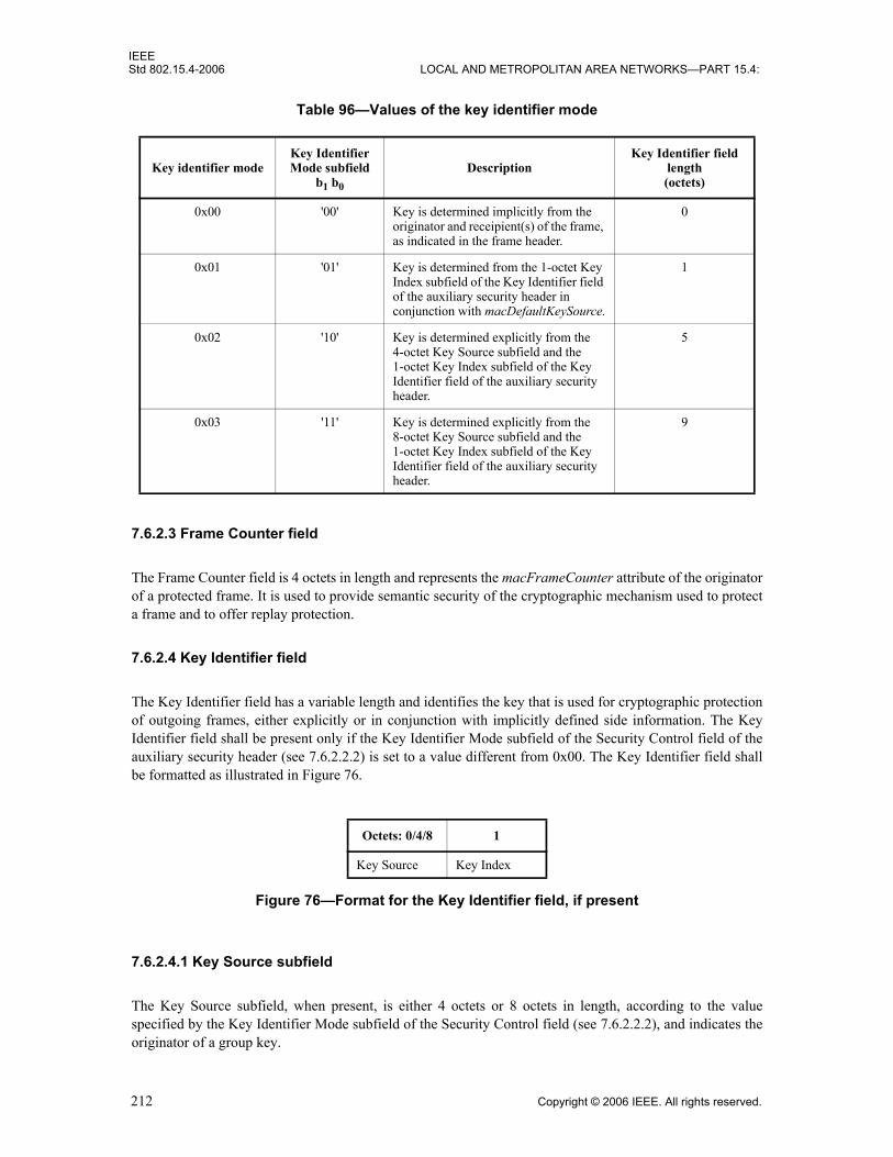
IEEEStd 802.15.4-2006 LOCAL AND METROPOLITAN AREA NETWORKS—PART 15.4:
7.6.2.3 Frame Counter field
The Frame Counter field is 4 octets in length and represents the macFrameCounter attribute of the originatorof a protected frame. It is used to provide semantic security of the cryptographic mechanism used to protecta frame and to offer replay protection.
7.6.2.4 Key Identifier field
The Key Identifier field has a variable length and identifies the key that is used for cryptographic protectionof outgoing frames, either explicitly or in conjunction with implicitly defined side information. The KeyIdentifier field shall be present only if the Key Identifier Mode subfield of the Security Control field of theauxiliary security header (see 7.6.2.2.2) is set to a value different from 0x00. The Key Identifier field shallbe formatted as illustrated in Figure 76.
7.6.2.4.1 Key Source subfield
The Key Source subfield, when present, is either 4 octets or 8 octets in length, according to the valuespecified by the Key Identifier Mode subfield of the Security Control field (see 7.6.2.2.2), and indicates theoriginator of a group key.
Table 96—Values of the key identifier mode
Key identifier modeKey Identifier Mode subfield
b1 b0
DescriptionKey Identifier field
length(octets)
0x00 '00' Key is determined implicitly from the originator and receipient(s) of the frame, as indicated in the frame header.
0
0x01 '01' Key is determined from the 1-octet Key Index subfield of the Key Identifier field of the auxiliary security header in conjunction with macDefaultKeySource.
1
0x02 '10' Key is determined explicitly from the 4-octet Key Source subfield and the 1-octet Key Index subfield of the Key Identifier field of the auxiliary security header.
5
0x03 '11' Key is determined explicitly from the 8-octet Key Source subfield and the 1-octet Key Index subfield of the Key Identifier field of the auxiliary security header.
9
Octets: 0/4/8 1
Key Source Key Index
Figure 76—Format for the Key Identifier field, if present
212 Copyright © 2006 IEEE. All rights reserved.

IEEEWIRELESS MAC AND PHY SPECIFICATIONS FOR LR-WPANS Std 802.15.4-2006
7.6.2.4.2 Key Index subfield
The Key Index subfield is 1 octet in length and allows unique identification of different keys with the sameoriginator.
It is the responsibility of each key originator to make sure that actively used keys that it issues have distinctkey indices and that the key indices are all different from 0x00.
7.6.3 Security operations
This subclause describes the parameters for the CCM* security operations, as specified in B.3.2.
7.6.3.1 Integer and octet representation
The integer and octet representation conventions specified in B.2 are used throughout 7.6.3.
7.6.3.2 CCM* Nonce
The CCM* nonce is a 13-octet string and is used for the advanced encryption standard (AES)-CCM* modeof operation (see B.2.2). The nonce shall be formatted as shown in Figure 77, with the leftmost field in thefigure defining the first (and leftmost) octets and the rightmost field defining the last (and rightmost) octet ofthe nonce.
The source address shall be set to the extended address aExtendedAddress of the device originating theframe, the frame counter to the value of the respective field in the auxiliary security header (see 7.6.2), andthe security level to the security level identifier corresponding to the Security Level subfield of the SecurityControl field of the auxiliary security header as defined in Table 95.
The source address, frame counter, and security level shall be represented as specified in 7.6.3.1.
7.6.3.3 CCM* prerequisites
Securing a frame involves the use of the CCM* mode encryption and authentication transformation, asdescribed in B.4.1. Unsecuring a frame involves the use of the CCM* decryption and authenticationchecking process, as described in B.4.2. The prerequisites for the CCM* forward and inversetransformations are as follows:
— The underlying block cipher shall be the AES encryption algorithm as specified in B.3.1.
— The bit ordering shall be as defined in 7.6.3.1.
— The length in octets of the Length field L shall be 2 octets.
— The length of the Authentication field M shall be 0 octets, 4 octets, 8 octets, or 16 octets, as required.
Octets: 8 4 1
Source address Frame counter Security level
Figure 77—CCM* nonce
Copyright © 2006 IEEE. All rights reserved. 213

IEEEStd 802.15.4-2006 LOCAL AND METROPOLITAN AREA NETWORKS—PART 15.4:
7.6.3.3.1 Authentication field length
The length of the Authentication field M for the CCM* forward transformation and the CCM* inversetransformation is determined from Table 95, using the Security Level subfield of the Security Control fieldof the auxiliary security header of the frame.
7.6.3.4 CCM* transformation data representation
This subclause describes how the inputs and output of the CCM* forward transformation, as described inB.4.1, are formed:
The inputs are— Key— Nonce— a data— m data
The output is c data.
7.6.3.4.1 Key and nonce data inputs
The Key data for the CCM* forward transformation is passed by the outgoing frame security proceduredescribed in 7.5.8.2.1. The Nonce data for the CCM* transformation is constructed as described in 7.6.3.2.
7.6.3.4.2 a data and m data
In the CCM* transformation process, the data fields shall be applied as in Table 97.
7.6.3.4.3 c data output
In the CCM* transformation process, the data fields that are applied, or right-concatenated and applied,represent octet strings.
Table 97—a data and m data for all security levels
Security level identifier a data m data
0x00 None None
0x01 MHR || Auxiliary security header || Nonpayload fields || Unsecured payload fields
None
0x02 MHR || Auxiliary security header || Nonpayload fields || Unsecured payload fields
None
0x03 MHR || Auxiliary security header || Nonpayload fields || Unsecured payload fields
None
0x04 None Unsecured payload fields
0x05 MHR || Auxiliary security header || Nonpayload fields Unsecured payload fields
0x06 MHR || Auxiliary security header || Nonpayload fields Unsecured payload fields
0x07 MHR || Auxiliary security header || Nonpayload fields Unsecured payload fields
214 Copyright © 2006 IEEE. All rights reserved.

IEEEWIRELESS MAC AND PHY SPECIFICATIONS FOR LR-WPANS Std 802.15.4-2006
The secured payload fields right-concatenated with the authentication tag shall substitute the unsecuredpayload field in the original unsecured frame to form the secured frame (see Table 98).
7.6.3.5 CCM* inverse transformation data representation
This subclause describes how the inputs and output of the CCM* inverse transformation, as described inB.4.2, are formed.
The inputs are— Key— Nonce— c data— a data
The output is m data.
7.6.3.5.1 Key and nonce data inputs
The Key data for the CCM* inverse transformation is passed by the incoming frame security proceduredescribed in 7.5.8.2.3. The Nonce data for the CCM* transformation is constructed as described in 7.6.3.2.
7.6.3.5.2 c data and a data
In the CCM* inverse transformation process, the data fields shall be applied as in Table 99.
Table 98—c data for all security levels
Security level identifier c data
0x00 None
0x01 MIC-32
0x02 MIC-64
0x03 MIC-128
0x04 Secured payload fields
0x05 Secured payload fields || MIC-32
0x06 Secured payload fields || MIC-64
0x07 Secured payload fields || MIC-128
Copyright © 2006 IEEE. All rights reserved. 215
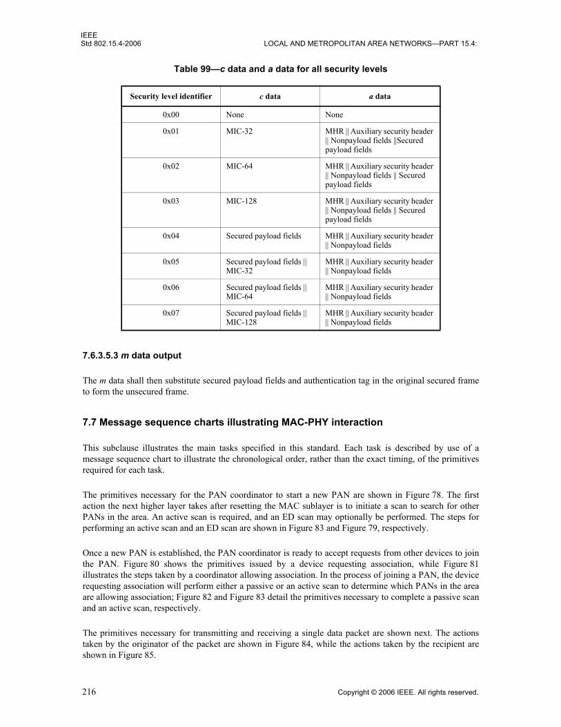
IEEEStd 802.15.4-2006 LOCAL AND METROPOLITAN AREA NETWORKS—PART 15.4:
7.6.3.5.3 m data output
The m data shall then substitute secured payload fields and authentication tag in the original secured frameto form the unsecured frame.
7.7 Message sequence charts illustrating MAC-PHY interaction
This subclause illustrates the main tasks specified in this standard. Each task is described by use of amessage sequence chart to illustrate the chronological order, rather than the exact timing, of the primitivesrequired for each task.
The primitives necessary for the PAN coordinator to start a new PAN are shown in Figure 78. The firstaction the next higher layer takes after resetting the MAC sublayer is to initiate a scan to search for otherPANs in the area. An active scan is required, and an ED scan may optionally be performed. The steps forperforming an active scan and an ED scan are shown in Figure 83 and Figure 79, respectively.
Once a new PAN is established, the PAN coordinator is ready to accept requests from other devices to jointhe PAN. Figure 80 shows the primitives issued by a device requesting association, while Figure 81illustrates the steps taken by a coordinator allowing association. In the process of joining a PAN, the devicerequesting association will perform either a passive or an active scan to determine which PANs in the areaare allowing association; Figure 82 and Figure 83 detail the primitives necessary to complete a passive scanand an active scan, respectively.
The primitives necessary for transmitting and receiving a single data packet are shown next. The actionstaken by the originator of the packet are shown in Figure 84, while the actions taken by the recipient areshown in Figure 85.
Table 99—c data and a data for all security levels
Security level identifier c data a data
0x00 None None
0x01 MIC-32 MHR || Auxiliary security header || Nonpayload fields ||Secured payload fields
0x02 MIC-64 MHR || Auxiliary security header || Nonpayload fields || Secured payload fields
0x03 MIC-128 MHR || Auxiliary security header || Nonpayload fields || Secured payload fields
0x04 Secured payload fields MHR || Auxiliary security header || Nonpayload fields
0x05 Secured payload fields || MIC-32
MHR || Auxiliary security header || Nonpayload fields
0x06 Secured payload fields || MIC-64
MHR || Auxiliary security header || Nonpayload fields
0x07 Secured payload fields || MIC-128
MHR || Auxiliary security header || Nonpayload fields
216 Copyright © 2006 IEEE. All rights reserved.

IEEEWIRELESS MAC AND PHY SPECIFICATIONS FOR LR-WPANS Std 802.15.4-2006
When a device becomes unable to communicate to its coordinator any longer, the device can use an orphanscan to rediscover its coordinator. The primitives necessary for the realignment of an orphaned device areshown in Figure 86.
Figure 78—PAN start message sequence chart—PAN coordinator
FFD nexthigher layer
FFDMAC
FFDPHY
MLME-RESET.request(SetDefaultPIB)
MLME-RESET.confirm
Beacon
Select PANId,ShortAddress,
LogicalChannel
PLME-SET-TRX-STATE.request(Rx off)
PLME-SET-TRX-STATE.confirm(SUCCESS)
MLME-SET.request(PANId)
MLME-SET.confirm(SUCCESS)
MLME-SCAN.request(Active)
MLME-SCAN.confirm(SUCCESS)
Performactive scan
MLME-SCAN.request(Energy detection)1
MLME-SCAN.confirm(SUCCESS)
Perform energydetection scan
MLME-SET.request(ShortAddress)
MLME-SET.confirm(SUCCESS)
PLME-SET.request(phyCurrentChannel)
PLME-SET.confirm(SUCCESS)
MLME-START.request
PLME-SET-TRX-STATE.request(Tx on)
PLME-SET-TRX-STATE.confirm(SUCCESS)
PD-DATA.request
PD-DATA.confirm (SUCCESS)
PLME-SET-TRX-STATE.request(Rx on)
PLME-SET-TRX-STATE.confirm(SUCCESS)
MLME-START.confirm(SUCCESS)2
1 The energy detection scan is optional.2 The MLME-START.confirm and PLME-SET-TRX-STATE.request primitives may not need to bein the order shown.
Copyright © 2006 IEEE. All rights reserved. 217

IEEEStd 802.15.4-2006 LOCAL AND METROPOLITAN AREA NETWORKS—PART 15.4:
Figure 79—ED scan message sequence chart
.
.
.
.
.
.
FFD MAC
FFD next higher layer
MLME-SCAN.request (Energy detection)
FFD PHY
PLME-SET-TRX-STATE.request (Rx on)
PLME-SET-TRX-STATE.confirm (SUCCESS)
aBaseSuperframeDuration * (2n + 1)symbols, where n = ScanDuration
PLME-SET-TRX-STATE.request (TRx off)
PLME-SET-TRX-STATE.confirm (SUCCESS)
PLME-ED.request
PLME-SET.request (phyCurrentChannel, the first channel)
PLME-SET.confirm (SUCCESS)
PLME-ED.confirm
PLME-ED.request
PLME-ED.confirm
PLME-SET.request (phyCurrentChannel, the last channel)
PLME-SET.confirm (SUCCESS)
.
.
.aBaseSuperframeDuration * (2n + 1)
symbols, where n = ScanDuration
PLME-ED.request
PLME-ED.confirm
PLME-ED.request
PLME-ED.confirm
MLME-SCAN.confirm (SUCCESS)
Energy detection measurement
Energy detection measurement
Energy detection
Energy detection measurement
218 Copyright © 2006 IEEE. All rights reserved.

IEEEWIRELESS MAC AND PHY SPECIFICATIONS FOR LR-WPANS Std 802.15.4-2006
Figure 80—Association message sequence chart—device
DevicePHY Device MAC Device next
higher layer
PD-DATA.confirm (SUCCESS)
PD-DATA.request
PLME-SET-TRX-STATE.request(Rx on)
PLME-SET-TRX-STATE.confirm(SUCCESS)
PD-DATA.request
PD-DATA.indication
MLME-SCAN.request (Passive)
Association request
Acknowledgment
Perform passive scanMLME-SCAN.confirm (SUCCESS)
PD-DATA.confirm (SUCCESS)
PLME-SET-TRX-STATE.request(Rx on)
Data request
PLME-SET-TRX-STATE.confirm(SUCCESS)
Acknowledgment
PLME-SET-TRX-STATE.request(Tx on)
Association response
Acknowledgment
macAckWaitDuration
Select a PAN based onlist of PAN descriptorsand set MAC PIBattributes accordingly
Perform CSMA algorithmand enable transmitter
MLME-ASSOCIATE.request
macResponseWaitTime
Perform CSMA algorithmand enable transmitter
macAckWaitDurationPD-DATA.indication
PD-DATA.indication
PLME-SET-TRX-STATE.confirm(SUCCESS)
PD-DATA.request
PD-DATA.confirm (SUCCESS)
PLME-SET-TRX-STATE.request(TRx off)
PLME-SET-TRX-STATE.confirm(SUCCESS)
MLME-ASSOCIATE.confirm
MLME-RESET.confirm (SUCCESS)
MLME-RESET.request
Copyright © 2006 IEEE. All rights reserved. 219
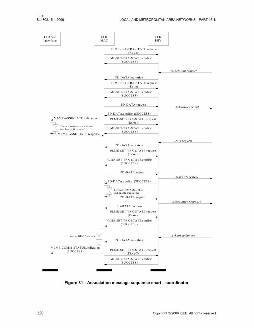
IEEEStd 802.15.4-2006 LOCAL AND METROPOLITAN AREA NETWORKS—PART 15.4:
Figure 81—Association message sequence chart—coordinator
FFD nexthigher layer
FFDMAC
FFDPHY
PLME-SET-TRX-STATE.request(Rx on)
PLME-SET-TRX-STATE.confirm(SUCCESS)
PD-DATA.indication
PLME-SET-TRX-STATE.request(Tx on)
PLME-SET-TRX-STATE.confirm(SUCCESS)
PD-DATA.request
PD-DATA.confirm (SUCCESS)MLME-ASSOCIATE.indication
Association request
Acknowledgment
Check resources and allocatean address, if required
MLME-ASSOCIATE.response
PLME-SET-TRX-STATE.request(Rx on)
PLME-SET-TRX-STATE.confirm(SUCCESS)
Data requestPD-DATA.indication
PLME-SET-TRX-STATE.request(Tx on)
PLME-SET-TRX-STATE.confirm(SUCCESS)
PD-DATA.requestAcknowldgement
PD-DATA.confirm (SUCCESS)
Perform CSMA algorithmand enable transmitter
PD-DATA.requestAssociation response
PLME-SET-TRX-STATE.request(Rx on)
PLME-SET-TRX-STATE.confirm(SUCCESS)
PD-DATA.confirm
PD-DATA.indicationAcknowledgment
PLME-SET-TRX-STATE.request(TRx off)
PLME-SET-TRX-STATE.confirm(SUCCESS)
macAckWaitDuration
MLME-COMM-STATUS.indication(SUCCESS)
220 Copyright © 2006 IEEE. All rights reserved.

IEEEWIRELESS MAC AND PHY SPECIFICATIONS FOR LR-WPANS Std 802.15.4-2006
Figure 82—Passive scan message sequence chart
Device nexthigher layer
DeviceMAC
MLME-SCAN.request(passive)
Beacon
PLME-SET-TRX-STATE.request(Rx on)
PLME-SET-TRX-STATE.confirm(SUCCESS)
aBaseSuperframeDuration * (2n + 1)symbols, where n = ScanDuration
(recording beacon frames)
PLME-SET-TRX-STATE.request(TRx off)
PLME-SET-TRX-STATE.confirm(SUCCESS)
DevicePHY
PLME-SET.request(phyCurrentChannel, the first channel)
PLME-SET.confirm(SUCCESS)
Beacon
PD-DATA.indication
PD-DATA.indication
Beacon
PLME-SET-TRX-STATE.request(Rx on)
PLME-SET-TRX-STATE.confirm(SUCCESS)
aBaseSuperframeDuration * (2n + 1)symbols, where n = ScanDuration
(recording beacon frames)
PLME-SET.request(phyCurrentChannel, the last channel)
PLME-SET.confirm(SUCCESS)
Beacon
PD-DATA.indication
PD-DATA.indication
PLME-SCAN.confirm(SUCCESS)
Copyright © 2006 IEEE. All rights reserved. 221

IEEEStd 802.15.4-2006 LOCAL AND METROPOLITAN AREA NETWORKS—PART 15.4:
Figure 83—Active scan message sequence chart
Device nexthigher layer
DeviceMAC
MLME-SCAN.request (active)
Beacon
PLME-SET-TRX-STATE.request (Rx on)
PLME-SET-TRX-STATE.confirm(SUCCESS)
aBaseSuperframeDuration * (2n + 1)symbols, where n = ScanDuration
(recording beacon frames)
PLME-SET-TRX-STATE.request (TRx off)
PLME-SET-TRX-STATE.confirm(SUCCESS)
DevicePHY
PLME-SET.request(phyCurrentChannel, the first channel)
PLME-SET.confirm (SUCCESS)
Beacon
PD-DATA.indication
PD-DATA.indication
Beacon
PLME-SET-TRX-STATE.request (Rx on)PLME-SET-TRX-STATE.confirm(SUCCESS)
aBaseSuperframeDuration * (2n + 1)symbols, where n = ScanDuration
(recording beacon frames)
PLME-SET.request(phyCurrentChannel, the last channel)
PLME-SET.confirm (SUCCESS)
Beacon
PD-DATA.indication
PD-DATA.indication
PLME-SCAN.confirm(SUCCESS)
Beacon requestPD-DATA.request
PD-DATA.confirm (SUCCESS)
PLME-SET-TRX-STATE.request (Tx on)
PLME-SET-TRX-STATE.confirm(SUCCESS)
Beacon requestPD-DATA.request
PD-DATA.confirm (SUCCESS)
PLME-SET-TRX-STATE.request (Tx on)PLME-SET-TRX-STATE.confirm(SUCCESS)
222 Copyright © 2006 IEEE. All rights reserved.
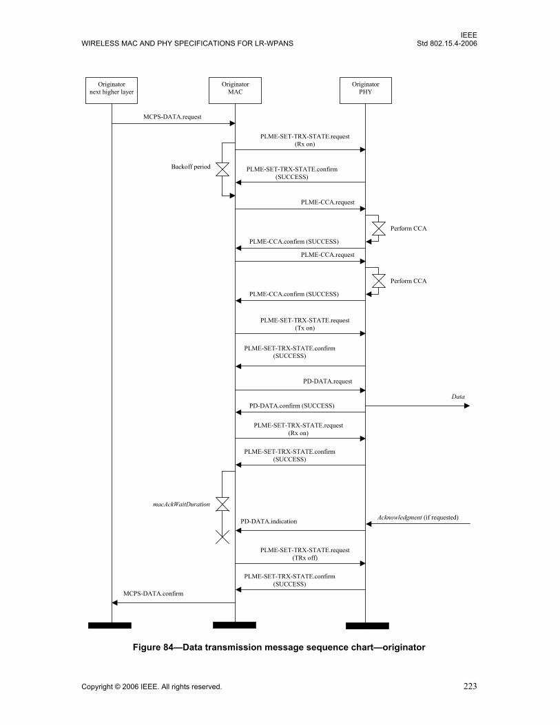
IEEEWIRELESS MAC AND PHY SPECIFICATIONS FOR LR-WPANS Std 802.15.4-2006
Figure 84—Data transmission message sequence chart—originator
Originator MAC
Data
Acknowledgment (if requested)
Originator next higher layer
MCPS-DATA.request
MCPS-DATA.confirm
Originator PHY
PD-DATA.request
PD-DATA.indication
PLME-SET-TRX-STATE.request (Rx on)
PLME-SET-TRX-STATE.confirm (SUCCESS)
PLME-CCA.request
Perform CCA
PLME-SET-TRX-STATE.request (Tx on)
PLME-SET-TRX-STATE.confirm (SUCCESS)
PLME-CCA.confirm (SUCCESS)
PLME-CCA.request
Perform CCA
PLME-CCA.confirm (SUCCESS)
PD-DATA.confirm (SUCCESS)
PLME-SET-TRX-STATE.request (Rx on)
PLME-SET-TRX-STATE.confirm (SUCCESS)
macAckWaitDuration
PLME-SET-TRX-STATE.request (TRx off)
PLME-SET-TRX-STATE.confirm (SUCCESS)
Backoff period
Copyright © 2006 IEEE. All rights reserved. 223
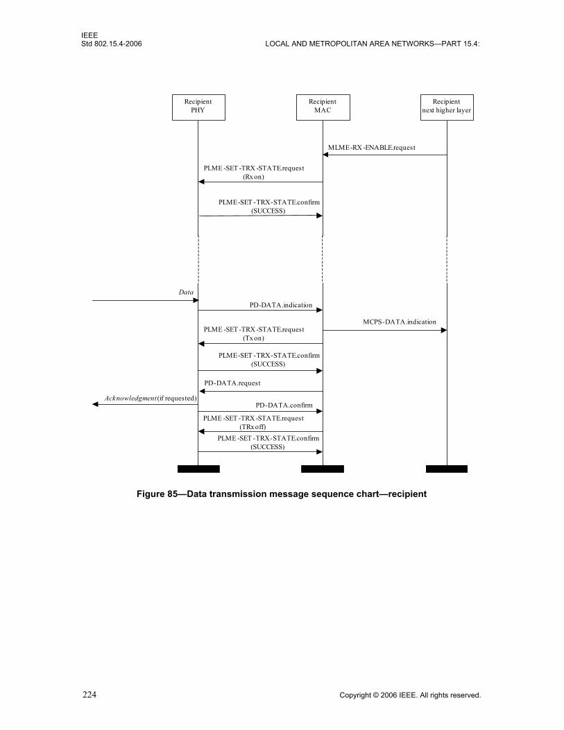
IEEEStd 802.15.4-2006 LOCAL AND METROPOLITAN AREA NETWORKS—PART 15.4:
Figure 85—Data transmission message sequence chart—recipient
RecipientMAC
Data
Acknowledgment (if requested)
Recipientnext higher layer
MCPS-DATA.indication
RecipientPHY
PD-DATA.indication
PD-DATA.request
MLME-RX -ENABLE.request
PLME -SET -TRX -STATE.request(Rx on)
PLME-SET -TRX-STATE.confirm(SUCCESS)
PLME -SET -TRX -STATE.request(Tx on)
PLME-SET -TRX-STATE.confirm(SUCCESS)
PD-DATA.confirm
PLME -SET -TRX -STATE.request(TRx off)
PLME -SET -TRX-STATE.confirm(SUCCESS)
224 Copyright © 2006 IEEE. All rights reserved.

IEEEWIRELESS MAC AND PHY SPECIFICATIONS FOR LR-WPANS Std 802.15.4-2006
Figure 86—Orphaned device realignment message sequence chart
Device nexthigher layer
DeviceMAC
MLME-SCAN.request(orphan)
Orphan notificationPD-DATA.request
PD-DATA.confirm(SUCCESS)
macResponseWaitTime symbols
DevicePHY
PLME-SET.request(phyCurrentChannel, the first channel)
PLME-SET.confirm(SUCCESS)
PD-DATA.indication
PLME-SET-TRX-STATE.request(Rx on)
PLME-SET-TRX-STATE.confirm(SUCCESS)
PLME-SET.request(phyCurrentChannel, the next channel)
PLME-SET.confirm(SUCCESS)
MLME-SCAN.confirm(SUCCESS)
PLME-SET-TRX-STATE.request(Tx on)
PLME-SET-TRX-STATE.confirm(SUCCESS)
PD-DATA.request
PD-DATA.confirm(SUCCESS)
PLME-SET-TRX-STATE.request(Rx on)
PLME-SET-TRX-STATE.confirm(SUCCESS)
PLME-SET-TRX-STATE.request(Tx on)
PLME-SET-TRX-STATE.confirm(SUCCESS)
Orphan notification
macResponseWaitTime symbols Coordinator realignment
PLME-SET-TRX-STATE.request(TRx off)
PLME-SET-TRX-STATE.confirm(SUCCESS)
Copyright © 2006 IEEE. All rights reserved. 225

IEEEStd 802.15.4-2006 LOCAL AND METROPOLITAN AREA NETWORKS—PART 15.4:
226 Copyright © 2006 IEEE. All rights reserved.
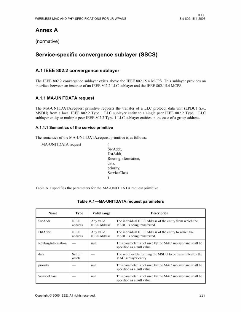
IEEEWIRELESS MAC AND PHY SPECIFICATIONS FOR LR-WPANS Std 802.15.4-2006
Annex A
(normative)
Service-specific convergence sublayer (SSCS)
A.1 IEEE 802.2 convergence sublayer
The IEEE 802.2 convergence sublayer exists above the IEEE 802.15.4 MCPS. This sublayer provides aninterface between an instance of an IEEE 802.2 LLC sublayer and the IEEE 802.15.4 MCPS.
A.1.1 MA-UNITDATA.request
The MA-UNITDATA.request primitive requests the transfer of a LLC protocol data unit (LPDU) (i.e.,MSDU) from a local IEEE 802.2 Type 1 LLC sublayer entity to a single peer IEEE 802.2 Type 1 LLCsublayer entity or multiple peer IEEE 802.2 Type 1 LLC sublayer entities in the case of a group address.
A.1.1.1 Semantics of the service primitive
The semantics of the MA-UNITDATA.request primitive is as follows:
Table A.1 specifies the parameters for the MA-UNITDATA.request primitive.
Table A.1—MA-UNITDATA.request parameters
Name Type Valid range Description
SrcAddr IEEE address
Any valid IEEE address
The individual IEEE address of the entity from which the MSDU is being transferred.
DstAddr IEEE address
Any valid IEEE address
The individual IEEE address of the entity to which the MSDU is being transferred.
RoutingInformation — null This parameter is not used by the MAC sublayer and shall be specified as a null value.
data Set of octets
— The set of octets forming the MSDU to be transmitted by the MAC sublayer entity.
priority — null This parameter is not used by the MAC sublayer and shall be specified as a null value.
ServiceClass — null This parameter is not used by the MAC sublayer and shall be specified as a null value.
MA-UNITDATA.request (SrcAddr,DstAddr,RoutingInformation,data,priority,ServiceClass)
Copyright © 2006 IEEE. All rights reserved. 227

IEEEStd 802.15.4-2006 LOCAL AND METROPOLITAN AREA NETWORKS—PART 15.4:
A.1.1.2 Appropriate usage
The MA-UNITDATA.request primitive is generated by a local IEEE 802.2 Type 1 LLC sublayer entitywhen an LPDU (MSDU) is to be transferred to a peer IEEE 802.2 Type 1 LLC sublayer entity or entities.
A.1.1.3 Effect on receipt
On receipt of the MA-UNITDATA.request primitive, the MAC sublayer entity shall begin the transmissionof the supplied MSDU.
The MAC sublayer first builds an MPDU to transmit from the supplied arguments. The MPDU shall betransmitted using the CSMA-CA algorithm in the contention period of the frame and without requesting ahandshake.
If the CSMA-CA algorithm indicates a busy channel, the MAC sublayer shall issue the MA-UNITDATA-STATUS.indication primitive with a status of CHANNEL_ACCESS_FAILURE. If the MPDU wassuccessfully transmitted, the MAC sublayer shall issue the MA-UNITDATA-STATUS.indication primitivewith a status of SUCCESS.
A.1.2 MA-UNITDATA.indication
The MA-UNITDATA.indication primitive indicates the transfer of an LPDU (i.e., MSDU) from the MACsublayer to the local IEEE 802.2 Type 1 LLC sublayer entity.
A.1.2.1 Semantics of the service primitive
The semantics of the MA-UNITDATA.indication primitive is as follows:
Table A.2 specifies the parameters for the MA-UNITDATA.indication primitive.
A.1.2.2 When generated
On receipt of a data packet at the local MAC sublayer entity, the FCS field is checked. If it is valid, the MACsublayer shall issue the MA-UNITDATA.indication primitive to the IEEE 802.2 Type 1 LLC sublayerentity, indicating the arrival of a MSDU. If the FCS is not valid, the packet shall be discarded, and the IEEE802.2 Type 1 LLC sublayer entity shall not be informed.
A.1.2.3 Appropriate usage
The appropriate usage of the MA-UNITDATA.indication primitive by the IEEE 802.2 Type 1 LLC sublayerentity is not specified in this standard.
MA-UNITDATA.indication (SrcAddr,DstAddr,RoutingInformation,data,ReceptionStatus,priority,ServiceClass)
228 Copyright © 2006 IEEE. All rights reserved.
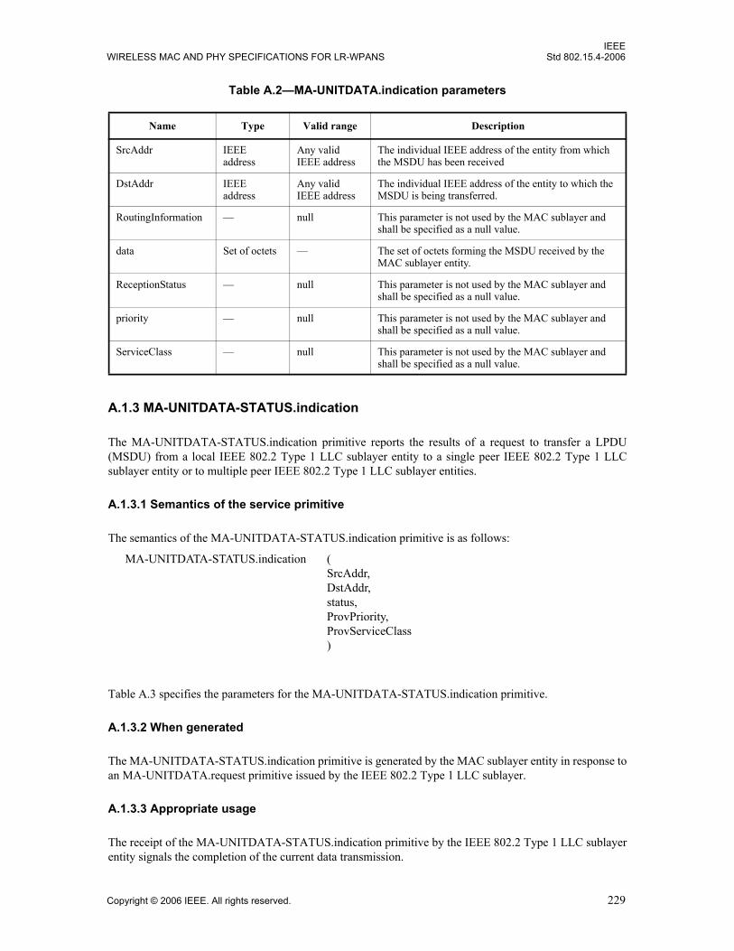
IEEEWIRELESS MAC AND PHY SPECIFICATIONS FOR LR-WPANS Std 802.15.4-2006
A.1.3 MA-UNITDATA-STATUS.indication
The MA-UNITDATA-STATUS.indication primitive reports the results of a request to transfer a LPDU(MSDU) from a local IEEE 802.2 Type 1 LLC sublayer entity to a single peer IEEE 802.2 Type 1 LLCsublayer entity or to multiple peer IEEE 802.2 Type 1 LLC sublayer entities.
A.1.3.1 Semantics of the service primitive
The semantics of the MA-UNITDATA-STATUS.indication primitive is as follows:
Table A.3 specifies the parameters for the MA-UNITDATA-STATUS.indication primitive.
A.1.3.2 When generated
The MA-UNITDATA-STATUS.indication primitive is generated by the MAC sublayer entity in response toan MA-UNITDATA.request primitive issued by the IEEE 802.2 Type 1 LLC sublayer.
A.1.3.3 Appropriate usage
The receipt of the MA-UNITDATA-STATUS.indication primitive by the IEEE 802.2 Type 1 LLC sublayerentity signals the completion of the current data transmission.
Table A.2—MA-UNITDATA.indication parameters
Name Type Valid range Description
SrcAddr IEEE address
Any valid IEEE address
The individual IEEE address of the entity from which the MSDU has been received
DstAddr IEEE address
Any valid IEEE address
The individual IEEE address of the entity to which the MSDU is being transferred.
RoutingInformation — null This parameter is not used by the MAC sublayer and shall be specified as a null value.
data Set of octets — The set of octets forming the MSDU received by the MAC sublayer entity.
ReceptionStatus — null This parameter is not used by the MAC sublayer and shall be specified as a null value.
priority — null This parameter is not used by the MAC sublayer and shall be specified as a null value.
ServiceClass — null This parameter is not used by the MAC sublayer and shall be specified as a null value.
MA-UNITDATA-STATUS.indication (SrcAddr,DstAddr,status,ProvPriority,ProvServiceClass)
Copyright © 2006 IEEE. All rights reserved. 229

IEEEStd 802.15.4-2006 LOCAL AND METROPOLITAN AREA NETWORKS—PART 15.4:
Table A.3—MA-UNITDATA-STATUS.indication parameters
Name Type Valid Range Description
SrcAddr IEEE address
Any valid IEEE address The individual IEEE address of the entity from which the MSDU has been transferred.
DstAddr IEEE address
Any valid IEEE address The individual IEEE address of the entity to which the MSDU has been transferred.
status Enumeration SUCCESS, TRANSMISSION_PENDING, NO_BEACON, or CHANNEL_ACCESS_FAILURE
The status of the last MSDU transmission.
ProvPriority — null This parameter is not used by the MAC sublayer and shall be specified as a null value.
ProvServiceClass — null This parameter is not used by the MAC sublayer and shall be specified as a null value.
230 Copyright © 2006 IEEE. All rights reserved.

IEEEWIRELESS MAC AND PHY SPECIFICATIONS FOR LR-WPANS Std 802.15.4-2006
Annex B
(normative)
CCM* mode of operation
B.1 Introduction
CCM* is a generic combined encryption and authentication block cipher mode. The CCM* mode coincideswith the original specification for the combined counter with CBC-MAC (cipher block chaining messageauthentication code) mode of operation (known as CCM) (ANSI X9.63-2001 [B1], Appendix A ofNIST Pub 800-38C [B16]) for messages that require authentication and, possibly, encryption, but also offerssupport for messages that require only encryption. Moreover, it can be used in implementation environmentsfor which the use of variable-length authentication tags, rather than fixed-length authentication tags only, isbeneficial.
B.2 Notation and representation
B.2.1 Strings and string operations
A string is a sequence of symbols over a specific set (e.g., the binary alphabet {0,1} or the set of all octets).The length of a string is the number of symbols it contains (over the same alphabet). The empty string is thestring of length 0. The right-concatenation of two strings x and y (over the same alphabet) of length m and n,respectively (notation: x || y), is the string z of length m + n that coincides with x on its leftmost (mostsignificant) m symbols and with y on its rightmost (least significant) n symbols. An octet is a symbol stringof length 8. In the context of this standard, all octets are strings over the binary alphabet.
B.2.2 Integers, octets, and their representation
Throughout this standard, the representation of integers as octet strings and of octet strings as binary stringsshall be fixed. All integers shall be represented as octet strings in most-significant-octet-first order. Alloctets shall be represented as bit strings of length eight in most-significant-bit-first order.
For example, the 32-bit integer 0x12345678 is represented as an octet string of {0x12, 0x34, 0x56, 0x78},and the first octet of that octet string is represented as a bit string of {0,0,0,1,0,0,1,0}.
B.3 Symmetric-key cryptographic building blocks
The symmetric-key cryptographic primitives and mechanisms are defined for use with all security-processing operations specified in this standard.
B.3.1 Block cipher
The block cipher used in this standard shall be the advanced encryption standard (AES)-128, as specified inFIPS Pub 197. This block cipher shall be used with symmetric keys with the same size as that of the blockcipher: 128 bits. The generation of these keys is outside the scope of this standard.
Copyright © 2006 IEEE. All rights reserved. 231

IEEEStd 802.15.4-2006 LOCAL AND METROPOLITAN AREA NETWORKS—PART 15.4:
B.3.2 Mode of operation
The block cipher mode of operation used in this specification shall be the generic CCM* mode of operation,as specified in B.4, with the following instantiations:
a) Each entity shall use the block cipher E as specified in B.3.1.b) All integers shall be represented as octet strings as specified in B.2.2.c) All octets shall be represented as binary strings as specified in B.2.2.d) The parameter L shall have the integer value 2.e) The parameter M shall have one of the following integer values: 0, 4, 8, or 16.
B.4 Specification of generic CCM* mode of operation
Prerequisites:
The following are the prerequisites for the operation of the generic CCM* mode:a) A block cipher encryption function E shall have been chosen, with a 128-bit block size. The length
in bits of the keys used by the chosen encryption function is denoted by keylen.b) A fixed representation of integers as octet strings shall have been chosen (e.g., most-significant-
octet-first order or least-significant-octet-first order).c) A fixed representation of octets as binary strings shall have been chosen (e.g., most-significant-bit-
first order or least-significant-bit-first order).d) The length L of the message Length field, in octets, shall have been chosen. Valid values for L are
the integers 2, 3, …, 8 (the value L = 1 is reserved).e) The length M of the Authentication field, in octets, shall have been chosen. Valid values for M are
the integers 0, 4, 6, 8, 10, 12, 14, and 16 (the value M = 0 corresponds to disabling authenticitybecause then the Authentication field is the empty string).
B.4.1 CCM* mode encryption and authentication transformation
Inputs:
The CCM* mode forward transformation takes the following as inputs:a) A bit string Key of length keylen bits to be used as the key. Each entity shall have evidence that
access to this key is restricted to the entity itself and its intended key sharing group member(s).b) A nonce N of 15 – L octets. Within the scope of any encryption key Key, the nonce value shall be
unique. c) An octet string m of length l(m) octets, where 0 ≤ l(m) < 28L.d) An octet string a of length l(a) octets, where 0 ≤ l(a) < 264.
The nonce N shall encode the potential values for M so that the actual value of M can be uniquelydetermined from N. The exact format of the nonce N is outside the scope of this specification and shall bedetermined and fixed by the actual implementation environment of the CCM* mode.
NOTE—The exact format of the nonce N is left to the application, to allow simplified hardware and softwareimplementations in particular settings. Actual implementations of the CCM* mode may restrict the values of M that areallowed throughout the life cycle of the encryption key Key to a strict subset of those allowed in the generic CCM*mode. If so, the format of the nonce N shall be such that one can uniquely determine from N the actually used value ofM in that particular subset. In particular, if M is fixed and the value M = 0 is not allowed, then there are no restrictionson N, in which case the CCM* mode reduces to the CCM mode.
232 Copyright © 2006 IEEE. All rights reserved.

IEEEWIRELESS MAC AND PHY SPECIFICATIONS FOR LR-WPANS Std 802.15.4-2006
Actions:
The CCM* mode forward transformation involves the execution, in order, of an input transformation(B.4.1.1), an authentication transformation (B.4.1.2), and an encryption transformation (B.4.1.3).
B.4.1.1 Input transformation
This step involves the transformation of the input strings a and m to the strings AuthData and PlainTextData,to be used by the authentication transformation and the encryption transformation, respectively.
This step involves the following steps, in order:a) Form the octet string representation L(a) of the length l(a) of the octet string a, as follows:
1) If l(a) = 0, then L(a) is the empty string.2) If 0 < l(a) < 216 – 28, then L(a) is the 2-octets encoding of l(a).3) If 216 – 28 ≤ l(a) < 232, then L(a) is the right-concatenation of the octet 0xff, the octet 0xfe, and
the 4-octet encoding of l(a). 4) If 232 ≤ l(a) < 264, then L(a) is the right-concatenation of the octet 0xff, the octet 0xff, and the
8-octet encoding of l(a).b) Right-concatenate the octet string L(a) with the octet string a itself. Note that the resulting string
contains l(a) and a encoded in a reversible manner.c) Form the padded message AddAuthData by right-concatenating the resulting string with the
smallest non-negative number of all-zero octets so that the octet string AddAuthData has lengthdivisible by 16.
d) Form the padded message PlaintextData by right-concatenating the octet string m with the smallestnon-negative number of all-zero octets so that the octet string PlaintextData has length divisibleby 16.
e) Form the message AuthData consisting of the octet strings AddAuthData and PlaintextData:AuthData = AddAuthData || PlaintextData.
B.4.1.2 Authentication transformation
The data AuthData that was established in B.4.1.1 shall be tagged using the tagging transformation asfollows:
a) Form the 1-octet Flags field consisting of the 1-bit Reserved field, the 1-bit Adata field, andparticular 3-bit representations of the integers M and L, as follows: Flags = Reserved || Adata || M || L.Here, the 1-bit Reserved field is reserved for future expansions and shall be set to '0'. The 1-bitAdata field is set to '0' if l(a) = 0 and set to '1' if l(a) > 0. The M field is the 3-bit representation of theinteger (M – 2)/2 if M > 0 and of the integer 0 if M = 0, in most-significant-bit-first order. TheL field is the 3-bit representation of the integer L – 1, in most-significant-bit-first order.
b) Form the 16-octet B0 field consisting of the 1-octet Flags field defined in step a) in this subclause,the (15 – L)-octet Nonce field N, and the L-octet representation of the Length field l(m), as follows:B0 = Flags || Nonce N || l(m).
c) Parse the message AuthData as B1 || B2 || … ||Bt, where each message block Bi is a 16-octet string. d) The CBC-MAC value Xt+1 is defined by
X0 := 0128; Xi+1 := E(Key, Xi ⊕ Bi) for i = 0, …, t. Here, E(K, x) is the ciphertext that results from encryption of the plaintext x, using the establishedblock cipher encryption function E with key K; the string 0128 is the 16-octet all-zero bit string.
Copyright © 2006 IEEE. All rights reserved. 233

IEEEStd 802.15.4-2006 LOCAL AND METROPOLITAN AREA NETWORKS—PART 15.4:
e) The authentication tag T is the result of omitting all but the leftmost M octets of the CBC-MACvalue Xt+1 thus computed.
B.4.1.3 Encryption transformation
The data PlaintextData that was established in B.4.1.1 (step d) and the authentication tag T that wasestablished in B.4.1.2 (step e) shall be encrypted using the encryption transformation as follows:
a) Form the 1-octet Flags field consisting of two 1-bit Reserved fields, and particular 3-bitrepresentations of the integers 0 and L, as follows:
Flags = Reserved || Reserved || 0 || L.
Here, the two 1-bit Reserved fields are reserved for future expansions and shall be set to '0'. The '0'field is the 3-bit representation of the integer 0, in most-significant-bit-first order. The L field is the3-bit representation of the integer L – 1, in most-significant-bit-first order.
b) Define the 16-octet Ai field consisting of the 1-octet Flags field defined in step a) in this subclause,the (15 – L)-octet Nonce field N, and the L-octet representation of the integer i, as follows:
Ai = Flags || Nonce N || Counter i, for i = 0, 1, 2, …
Note that this definition ensures that all the Ai fields are distinct from the B0 fields that are actuallyused, as those have a Flags field with a nonzero encoding of M in the positions where all Ai fieldshave an all-zero encoding of the integer 0 (see B.4.1.2, step b).
c) Parse the message PlaintextData as M1 || … ||Mt, where each message block Mi is a 16-octet string.
d) The ciphertext blocks C1, …, Ct are defined by
Ci := E(Key, Ai) ⊕ Mi for i = 1, 2, …, t.
e) The string Ciphertext is the result of omitting all but the leftmost l(m) octets of the string C1 || … ||Ct.
f) Define the 16-octet encryption block S0 by
S0:= E(Key, A0).
g) The encrypted authentication tag U is the result of XOR-ing the string consisting of the leftmostM octets of S0 and the authentication tag T.
Output:
If any of the above operations has failed, then output “invalid.” Otherwise, output the right-concatenation cof the encrypted message Ciphertext and the encrypted authentication tag U.
B.4.2 CCM* mode decryption and authentication checking transformation
Inputs:
The CCM* mode inverse transformation takes the following as inputs:
a) A bit string Key of length keylen bits to be used as the key. Each entity shall have evidence thataccess to this key is restricted to the entity itself and its intended key-sharing group member(s).
b) A nonce N of 15 – L octets. Within the scope of any encryption key Key, the nonce value shall beunique.
c) An octet string c of length l(c) octets, where 0 ≤ l(c) – M < 28L.
d) An octet string a of length l(a) octets, where 0 ≤ l(a) < 264.
234 Copyright © 2006 IEEE. All rights reserved.

IEEEWIRELESS MAC AND PHY SPECIFICATIONS FOR LR-WPANS Std 802.15.4-2006
Actions:
The CCM* mode inverse transformation involves the execution, in order, of a decryption transformation(B.4.2.1) and an authentication checking transformation (B.4.2.2).
B.4.2.1 Decryption transformation
The decryption transformation involves the following steps, in order:a) Parse the message c as C ||U, where the rightmost string U is an M-octet string. If this operation fails,
output “invalid” and stop. U is the purported encrypted authentication tag. Note that the leftmoststring C has length l(c) – M octets.
b) Form the padded message CiphertextData by right-concatenating the string C with the smallest non-negative number of all-zero octets so that the octet string CiphertextData has length divisible by 16.
c) Use the encryption transformation in B.4.1.3, with as inputs the data CipherTextData and the tag U.d) Parse the output string resulting from applying this transformation as m || T, where the rightmost
string T is an M-octet string. T is the purported authentication tag. Note that the leftmost string m haslength l(c) – M octets.
B.4.2.2 Authentication checking transformation
The authentication checking transformation involves the following steps, in order:a) Form the message AuthData using the input transformation in B.4.1.1, with as inputs the string a
and the octet string m that was established in B.4.2.1 (step d). b) Use the authentication transformation in B.4.1.2, with as input the message AuthData.c) Compare the output tag MACTag resulting from this transformation with the tag T that was
established in B.4.2.1 (step d). If MACTag = T, output “valid”; otherwise, output “invalid” and stop.
Output:
If any of the above verifications has failed, then output “invalid,” and reject the octet strings a and m.Otherwise, accept the octet strings a and m, and accept one of the key sharing group member(s) as the sourceof a and m.
B.4.3 Restrictions
All implementations shall limit the total amount of data that is encrypted with a single key. The CCM*encryption and authentication transformation shall invoke not more than 261 block cipher encryptionfunction invocations with the same key in total.
The CCM* decryption and authentication checking transformation shall not expose any information if anyverification check fails. The only information that may be exposed in this case is that the authenticityverification transformation failed; all other information, such as the purported plaintext, shall be destroyed.
NOTE 1—With regard to security of the CCM* mode of operation, the CCM* mode coincides with the original CCMmode specification (ANSI X9.63-2001 [B1]) for messages that require authentication and, possibly, encryption, but alsooffers support for messages that require only encryption. Moreover, it can be used in implementation environments forwhich the use of variable-length authentication tags, rather than fixed-length authentication tags only, is beneficial. Aswith the CCM mode, the CCM* mode requires only one key. The CCM* specification differs from the CCMspecification, as follows:
Copyright © 2006 IEEE. All rights reserved. 235

IEEEStd 802.15.4-2006 LOCAL AND METROPOLITAN AREA NETWORKS—PART 15.4:
— The CCM* mode allows the length of the Authentication field M to be zero as well (the value M = 0 correspond-ing to disabling authenticity because then the Authentication field is the empty string).
— The CCM* mode imposes a further restriction on the nonce N: it shall encode the potential values for M so thatone can uniquely determine from N the actually used value of M.
As a result, if M is fixed and the value M = 0 is not allowed, then there are no additional restrictions on N, in which casethe CCM* mode reduces to the CCM mode. In particular, the proof of the CCM mode applies (Jonsson [B13] and[B14]).
For fixed-length authentication tags, the CCM* mode is equally secure as the original CCM mode. For variable-lengthauthentication tags, the CCM* mode completely avoids, by design, the vulnerabilities that do apply to the original CCMmode.
For fixed-length authentication tags, the security proof of the original CCM mode carries over to that of the CCM* mode(also for M = 0), by observing that the proof of the original CCM mode relies on the following properties, which slightlyrelax those stated in Jonsson [B13] and [B14] (relaxed property indicated in italics):
— The B0 field uniquely determines the value of the nonce N.— The authentication transformation operates on input strings B0 || B1 || B2 || … || Bt from which one can uniquely
determine the input strings a and m (as well as the nonce N). In fact, for any two input strings corresponding todistinct triples (N, m, a), neither one is a prefix string of the other.
— All the Ai fields are distinct from the B0 fields that are actually used (over the lifetime of the key), as those havea Flags field with a nonzero encoding of M in the positions where all Ai fields have an all-zero encoding of theinteger 0.
Hence, if M is fixed, then the CCM* mode offers the same security properties as the original CCM mode: confidentialityover the input string m and data authenticity over the input strings a and m, relative to the length of the authenticationtag. Obviously, if M = 0, then no data authenticity is provided by the CCM* mode itself (but may be provided by anexternal mechanism).
For variable-length authentication tags, the original CCM mode is known to be vulnerable to specific attacks (see, e.g.,Section 3.4 of Rogaway and Wagner [B17]). These attacks may arise with the original CCM mode because thedecryption transformation does not depend on the length of the authentication tag itself. The CCM* mode avoids theseattacks altogether, by requiring that one shall be able to uniquely determine the length of the applicable authenticationtag from the Ai fields (i.e., from the counters blocks).
NOTE 2—With regard to the interoperability between CCM mode and CCM* mode of operation, the CCM* modereduces to the CCM mode in all implementation environments where the length of the authentication tag is fixed andwhere the value M = 0 (encryption-only) is not allowed. In particular, the CCM* mode is compatible with the CCMmode, as specified in IEEE Std 802.11i™-2004 (for WLANs) [B7], IEEE Std 802.15.3™-2003 (for WPANs) [B10], andIEEE Std 802.15.4-2003 (for older WPANs).
NOTE 3—For test vectors for cryptographic building blocks, see Annex C.
236 Copyright © 2006 IEEE. All rights reserved.

IEEEWIRELESS MAC AND PHY SPECIFICATIONS FOR LR-WPANS Std 802.15.4-2006
Annex C
(informative)
Test vectors for cryptographic building blocks
With regard to the CCM* mode of operation (see Annex B), this annex provides sample test vectors for theIEEE 802.15.4 community, aimed at assisting in building interoperable security implementations.
C.1 AES block cipher
See FIPS Pub 197 for sample test vectors for the block cipher specified in B.3.1.
C.2 Mode of operation
This subclause provides sample test vectors for the mode of operation as specified in B.3.2, illustrated in thecontext of different MAC frame types.
C.2.1 MAC beacon frame
C.2.1.1 Description
The example below illustrates security processing of a beacon frame that is transmitted by the coordinatorusing its extended source address. In this example, the Superframe Specification field is set to 0xCF55 (e.g.,beacon order and superframe order have integer value 5, while the final CAP slot has integer value 15), andthere are no pending addresses. This example uses source address 0xacde480000000001, PAN identifier0x4321, and beacon payload 0x51 0x52 0x53 0x54; the frame counter has integer value 5. The security levelis set to 0x02 (MIC-64, or 64-bit data authenticity).
For simplicity, all frames in this example are shown without the FCS field (because security processing isindependent of it).
Secured beacon frame:
08 D0 84 21 43 01 00 00 00 00 48 DE AC || 02 05 00 00 00 || 55 CF 00 00 51 52 53 54 22 3B C1 EC 84 1AB5 53.
Corresponding unsecured beacon frame:
00 C0 84 21 43 01 00 00 00 00 48 DE AC || 55 CF 00 00 51 52 53 54.
Prerequisite:
The following prerequisite is established for this mode of operation: the parameter M shall have the integervalue 8.
Copyright © 2006 IEEE. All rights reserved. 237

IEEEStd 802.15.4-2006 LOCAL AND METROPOLITAN AREA NETWORKS—PART 15.4:
C.2.1.2 CCM* mode encryption and authentication transformation
Inputs:
The inputs to the CCM* mode forward transformation are as follows:a) The key Key of size keylen = 128 bits to be used:
Key = C0 C1 C2 C3 C4 C5 C6 C7 C8 C9 CA CB CC CD CE CF.b) The nonce N of 15 – L = 13 octets to be used:
Nonce = AC DE 48 00 00 00 00 01 || 00 00 00 05 || 02.c) The octet string m of length l(m) = 0 octets to be used:
m = (empty string).d) The octet string a of length l(a) = 26 octets to be used:
a = 08 D0 84 21 43 01 00 00 00 00 48 DE AC || 02 || 05 00 00 00 || 55 CF 00 00 51 52 53 54.
Actions:
The CCM* mode forward transformation involves the execution, in order, of an input transformation(C.2.1.2.1), an authentication transformation (C.2.1.2.2), and an encryption transformation (C.2.1.2.3).
C.2.1.2.1 Input transformation
This step involves the transformation of the input strings a and m to the strings AuthData and PlainTextData,to be used by the authentication transformation and the encryption transformation, respectively.
a) Form the octet string representation L(a) of the length l(a) of the octet string a:L(a) = 00 1A.
b) Right-concatenate the octet string L(a) with the octet string a itself:L(a) || a = 00 1A || 08 D0 84 21 43 01 00 00 00 00 48 DE AC 02 05 00 00 00 55 CF 00 00
51 52 53 54.c) Form the padded message AddAuthData by right-concatenating the resulting string with the
smallest non-negative number of all-zero octets so that the octet string AddAuthData has lengthdivisible by 16:
AddAuthData = 00 1A 08 D0 84 21 43 01 00 00 00 00 48 DE AC 02 05 00 00 00 55 CF 00 00 51 52 53 54 00 00 00 00.
d) Form the padded message PlaintextData by right-concatenating the octet string m with the smallestnon-negative number of all-zero octets so that the octet string PlaintextData has length divisibleby 16:
PlaintextData = (empty string). e) Form the message AuthData consisting of the octet strings AddAuthData and PlaintextData:
AuthData = 00 1A 08 D0 84 21 43 01 00 00 00 00 48 DE AC 02 05 00 00 00 55 CF 00 00 51 52 53 54 00 00 00 00.
C.2.1.2.2 Authentication transformation
The data AuthData that was established in C.2.1.2.1 shall be tagged using the tagging transformation asfollows:
a) Form the 1-octet Flags field: Flags = 59.
238 Copyright © 2006 IEEE. All rights reserved.

IEEEWIRELESS MAC AND PHY SPECIFICATIONS FOR LR-WPANS Std 802.15.4-2006
b) Form the 16-octet B0 field:B0 = 59 || AC DE 48 00 00 00 00 01 00 00 00 05 02 || 00 00.
c) Parse the message AuthData as B1 || B2, where each message block Bi is a 16-octet string. d) The CBC-MAC value X3 is computed as shown in Table C.1.
e) The authentication tag T is the result of omitting all but the leftmost M = 8 octets of the CBC-MACvalue X3:
T = AB 6B 19 E7 5B 75 2D 9A.
C.2.1.2.3 Encryption transformation
The data PlaintextData that was established in C.2.1.2.1 (step d), and the authentication tag T that wasestablished in C.2.1.2.2 (step e) shall be encrypted using the encryption transformation as follows:
a) Form the 1-octet Flags field:Flags = 01.
b) Define the 16-octet Ai field as shown in Table C.2.
c) Define the 16-octet encryption block S0:S0:= E(Key, A0) = 89 50 D8 0B DF 6F 98 C9 63 F2 D5 A1 08 A1 55 C7.
d) The encrypted authentication tag U is the result of XOR-ing the string consisting of the leftmostM = 8 octets of S0 and the authentication tag T:
U = 22 3B C1 EC 84 1A B5 53
Output:
The octet string c = 22 3B C1 EC 84 1A B5 53.
Table C.1—Computation of CBC-MAC value
i Bi Xi
0 59 AC DE 48 00 00 00 00 01 00 00 00 05 02 00 00 00 00 00 00 00 00 00 00 00 00 00 00 00 00 00 00
1 00 1A 08 D0 84 21 43 01 00 00 00 00 48 DE AC 02 C4 A4 D0 BD 70 73 7E 32 11 2E 51 9A CA A2 01 F1
2 05 00 00 00 55 CF 00 00 51 52 53 54 00 00 00 00 A9 70 2C 6E E1 7E DE E0 C7 32 88 0A 40 41 7F 9C
3 — AB 6B 19 E7 5B 75 2D 9A 6E F0 CC 13 09 98 EB D0
Table C.2—Ai fields
i Ai
0 01 AC DE 48 00 00 00 00 01 00 00 00 05 02 00 00
Copyright © 2006 IEEE. All rights reserved. 239

IEEEStd 802.15.4-2006 LOCAL AND METROPOLITAN AREA NETWORKS—PART 15.4:
C.2.1.3 CCM* mode decryption and authentication checking transformation
Inputs:
The inputs to the CCM* mode inverse transformation are as follows:a) The key Key of size keylen = 128 bits to be used:
Key = C0 C1 C2 C3 C4 C5 C6 C7 C8 C9 CA CB CC CD CE CF.b) The nonce N of 15 – L = 13 octets to be used:
Nonce = AC DE 48 00 00 00 00 01 || 00 00 00 05 || 02.c) The octet string c of length l(c) = 8 octets to be used:
c = 22 3B C1 EC 84 1A B5 53.d) The octet string a of length l(a) = 26 octets to be used:
a = 08 D0 84 21 43 01 00 00 00 00 48 DE AC || 02 || 05 00 00 00 || 55 CF 00 00 51 52 53 54.
Actions:
The CCM* mode inverse transformation involves the execution, in order, of a decryption transformation(C.2.1.3.1) and an authentication checking transformation (C.2.1.3.2).
C.2.1.3.1 Decryption transformation
The decryption transformation involves the following steps, in order:a) Parse the message c as C ||U, where the rightmost string U is an 8-octet string:
C = (empty string);U = 22 3B C1 EC 84 1A B5 53.
b) Form the 1-octet Flags field: Flags = 01.
c) Define the 16-octet Ai field as shown in Table C.3.
d) Define the 16-octet encryption block S0:S0 = E(Key, A0) = 89 50 D8 0B DF 6F 98 C9 63 F2 D5 A1 08 A1 55 C7.
e) The purported authentication tag T is the result of XOR-ing the string consisting of the leftmostM = 8 octets of S0 and the octet string U:
T = AB 6B 19 E7 5B 75 2D 9A.
Table C.3—Ai fields
i Ai
0 01 AC DE 48 00 00 00 00 01 00 00 00 05 02 00 00
240 Copyright © 2006 IEEE. All rights reserved.

IEEEWIRELESS MAC AND PHY SPECIFICATIONS FOR LR-WPANS Std 802.15.4-2006
C.2.1.3.2 Authentication checking transformation
The authentication checking transformation involves the following steps, in order: a) Form the message AuthData using the input transformation in C.2.1.2.1, with as inputs the string a
and the octet string m = (empty string):AuthData = 00 1A 08 D0 84 21 43 01 00 00 00 00 48 DE AC 02 05 00 00 00 55 CF
00 00 51 52 53 54 00 00 00 00.b) Use the authentication transformation in C.2.1.2.2, with as input the message AuthData to compute
the authentication tag MACTag:MACTag = AB 6B 19 E7 5B 75 2D 9A.
c) Compare the output tag MACTag resulting from this transformation with the tag T that wasestablished in C.2.1.3.1 (step e):
T = AB 6B 19 E7 5B 75 2D 9A = MACTag.
Output:
Because MACTag = T, output “valid,” accept the octet strings a and m, and accept one of the key sharinggroup member(s) as the source of a and m.
C.2.2 MAC data frame
C.2.2.1 Description
The example below illustrates security processing of a data frame that is transmitted using extendedaddresses, with PAN identifier compression and acknowledgment enabled. This example uses sourceaddress 0xacde480000000001, destination address 0xacde480000000002, PAN identifier 0x4321, and datapayload 0x61 0x62 0x63 0x64; the frame counter has integer value 5. The security level is set to 0x04 (ENC,or data confidentiality without data authenticity).
For simplicity, all frames in this example are shown without the FCS field (because security processing isindependent of it).
Secured data frame:
69 DC 84 21 43 02 00 00 00 00 48 DE AC 01 00 00 00 00 48 DE AC || 04 05 00 00 00 || D4 3E 02 2B.
Corresponding unsecured data frame:
61 CC 84 21 43 02 00 00 00 00 48 DE AC 01 00 00 00 00 48 DE AC || 61 62 63 64.
Prerequisite:
The following prerequisite is established for this mode of operation: the parameter M shall have the integervalue 0.
C.2.2.2 CCM* mode encryption and authentication transformation
Inputs:
The inputs to the CCM* mode forward transformation are as follows:
Copyright © 2006 IEEE. All rights reserved. 241
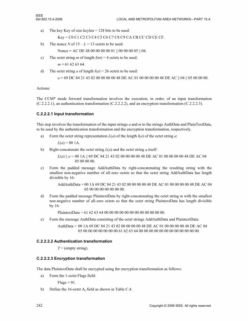
IEEEStd 802.15.4-2006 LOCAL AND METROPOLITAN AREA NETWORKS—PART 15.4:
a) The key Key of size keylen = 128 bits to be used:
Key = C0 C1 C2 C3 C4 C5 C6 C7 C8 C9 CA CB CC CD CE CF.
b) The nonce N of 15 – L = 13 octets to be used:
Nonce = AC DE 48 00 00 00 00 01 || 00 00 00 05 || 04.
c) The octet string m of length l(m) = 4 octets to be used:
m = 61 62 63 64.
d) The octet string a of length l(a) = 26 octets to be used:
a = 69 DC 84 21 43 02 00 00 00 00 48 DE AC 01 00 00 00 00 48 DE AC || 04 || 05 00 00 00.
Actions:
The CCM* mode forward transformation involves the execution, in order, of an input transformation(C.2.2.2.1), an authentication transformation (C.2.2.2.2), and an encryption transformation (C.2.2.2.3).
C.2.2.2.1 Input transformation
This step involves the transformation of the input strings a and m to the strings AuthData and PlainTextData,to be used by the authentication transformation and the encryption transformation, respectively.
a) Form the octet string representation L(a) of the length l(a) of the octet string a:
L(a) = 00 1A.
b) Right-concatenate the octet string L(a) and the octet string a itself:
L(a) || a = 00 1A || 69 DC 84 21 43 02 00 00 00 00 48 DE AC 01 00 00 00 00 48 DE AC 0405 00 00 00.
c) Form the padded message AddAuthData by right-concatenating the resulting string with thesmallest non-negative number of all-zero octets so that the octet string AddAuthData has lengthdivisible by 16:
AddAuthData = 00 1A 69 DC 84 21 43 02 00 00 00 00 48 DE AC 01 00 00 00 00 48 DE AC 0405 00 00 00 00 00 00 00.
d) Form the padded message PlaintextData by right-concatenating the octet string m with the smallestnon-negative number of all-zero octets so that the octet string PlaintextData has length divisibleby 16:
PlaintextData = 61 62 63 64 00 00 00 00 00 00 00 00 00 00 00 00.
e) Form the message AuthData consisting of the octet strings AddAuthData and PlaintextData:
AuthData = 00 1A 69 DC 84 21 43 02 00 00 00 00 48 DE AC 01 00 00 00 00 48 DE AC 0405 00 00 00 00 00 00 00 61 62 63 64 00 00 00 00 00 00 00 00 00 00 00 00.
C.2.2.2.2 Authentication transformationT = (empty string).
C.2.2.2.3 Encryption transformation
The data PlaintextData shall be encrypted using the encryption transformation as follows:
a) Form the 1-octet Flags field:
Flags = 01.
b) Define the 16-octet Ai field as shown in Table C.4.
242 Copyright © 2006 IEEE. All rights reserved.

IEEEWIRELESS MAC AND PHY SPECIFICATIONS FOR LR-WPANS Std 802.15.4-2006
c) Parse the message PlaintextData as M1, where each message block Mi is a 16-octet string.d) The ciphertext block C1 is computed as shown in Table C.5.
e) The string Ciphertext is the result of omitting all but the leftmost l(m) = 4 octets of the string C1:CipherText = D4 3E 02 2B.
Output:
c = D4 3E 02 2B.
C.2.2.3 CCM* mode decryption and authentication checking transformation
Inputs:
The inputs to the CCM* mode inverse transformation are as follows:a) The key Key of size keylen = 128 bits to be used:
Key = C0 C1 C2 C3 C4 C5 C6 C7 C8 C9 CA CB CC CD CE CF.b) The nonce N of 15 – L = 13 octets to be used:
Nonce = AC DE 48 00 00 00 00 01 || 00 00 00 05 || 04.c) The octet string c of length l(c) = 4 octets to be used:
c = D4 3E 02 2B. d) The octet string a of length l(a) = 26 octets to be used:
a = 69 DC 84 21 43 02 00 00 00 00 48 DE AC 01 00 00 00 00 48 DE AC || 04 || 05 00 00 00.
Actions:
The CCM* mode inverse transformation involves the execution, in order, of a decryption transformation(C.2.2.3.1) and an authentication checking transformation (C.2.2.3.2).
C.2.2.3.1 Decryption transformation
The decryption transformation involves the following steps, in order:a) Parse the message c as C ||U, where the rightmost string U is a 0-octet string:
C = D4 3E 02 2B. U = (empty string).
Table C.4—Ai fields
i Ai
1 01 AC DE 48 00 00 00 00 01 00 00 00 05 04 00 01
Table C.5—Computation of ciphertext
i AES(Key, Ai) Ci = AES(Key, Ai) ⊕ Mi
1 B5 5C 61 4F A6 8B 7E E0 CB 77 37 EB A8 1D 33 41 D4 3E 02 2B A6 8B 7E E0 CB 77 37 EB A8 1D 33 41
Copyright © 2006 IEEE. All rights reserved. 243

IEEEStd 802.15.4-2006 LOCAL AND METROPOLITAN AREA NETWORKS—PART 15.4:
b) Form the padded message CiphertextData by right-concatenating the string C with the smallestnon-negative number of all-zero octets so that the octet string CiphertextData has length divisibleby 16:
CipherTextData = D4 3E 02 2B 00 00 00 00 00 00 00 00 00 00 00 00. c) Form the 1-octet Flags field:
Flags = 01. d) Define the 16-octet Ai field as shown in Table C.6.
e) Parse the message CiphertextData as C1, where each message block Ci is a 16-octet string.f) The plaintext block P1 is computed as shown in Table C.7.
g) The octet string m is the result of omitting all but the leftmost l(m) = 4 octets of the string P1:m = 61 62 63 64.
h) The purported authentication tag T is the empty string:T = (empty string).
C.2.2.3.2 Authentication checking transformation
The authentication checking transformation involves the following steps, in order: a) Form the message AuthData using the input transformation in C.2.2.2.1, with as inputs the string a
and the octet string m that was established in C.2.2.3.1 (step g):AuthData = 00 1A 69 DC 84 21 43 02 00 00 00 00 48 DE AC 01 00 00 00 00 48 DE AC
04 05 00 00 00 00 00 00 00 61 62 63 64 00 00 00 00 00 00 00 00 00 00 00 00. b) Use the authentication transformation in C.2.2.2.2, with as input the message AuthData to compute
the authentication tag MACTag:MACTag = (empty string).
c) Compare the output tag MACTag resulting from this transformation with the tag T that wasestablished in C.2.2.3.1 (step h):
T = (empty string) = MACTag.
Output:
Because MACTag = T, output “valid,” accept the octet strings a and m, and accept one of the key sharinggroup member(s) as the source of a and m.
Table C.6—Ai fields
i Ai
1 01 AC DE 48 00 00 00 00 01 00 00 00 05 04 00 01
Table C.7—Computation of plaintext
i AES(Key, Ai) Pi = AES(Key, Ai) ⊕ Ci
1 B5 5C 61 4F A6 8B 7E E0 CB 77 37 EB A8 1D 33 41 61 62 63 64 00 00 00 00 00 00 00 00 00 00 00 00
244 Copyright © 2006 IEEE. All rights reserved.

IEEEWIRELESS MAC AND PHY SPECIFICATIONS FOR LR-WPANS Std 802.15.4-2006
C.2.3 MAC command frame
C.2.3.1 Description
The example below illustrates security processing of an association request command frame that istransmitted by a FFD using extended addresses, with acknowledgment enabled. In this example, theCapability field is set to 0xCE. This example uses source address 0xacde480000000001, destination address0xacde480000000002, PAN identifier 0x4321, and command payload 0xCE; the frame counter has integervalue 5. The security level is set to 0x06 (ENC-MIC-64, or data confidentiality with 64-bit dataauthenticity).
For simplicity, all frames in this example are shown without the FCS field (because security processing isindependent of it).
Secured command frame:
2B DC 84 21 43 02 00 00 00 00 48 DE AC FF FF 01 00 00 00 00 48 DE AC || 06 05 00 00 00 || 01 D8 4F DE52 90 61 F9 C6 F1.
Corresponding unsecured command frame:
23 CC 84 21 43 02 00 00 00 00 48 DE AC FF FF 01 00 00 00 00 48 DE AC || 01 CE.
Prerequisite:
The following prerequisite is established for this mode of operation: the parameter M shall have the integervalue 8.
C.2.3.2 CCM* mode encryption and authentication transformation
Inputs:
The inputs to the CCM* mode forward transformation are as follows:a) The key Key of size keylen = 128 bits to be used:
Key = C0 C1 C2 C3 C4 C5 C6 C7 C8 C9 CA CB CC CD CE CF.b) The nonce N of 15 – L = 13 octets to be used:
Nonce = AC DE 48 00 00 00 00 01 || 00 00 00 05 || 06.c) The octet string m of length l(m) = 1 octets to be used:
m = CE.d) The octet string a of length l(a) = 29 octets to be used:
a = 2B DC 84 21 43 02 00 00 00 00 48 DE AC FF FF 01 00 00 00 00 48 DE AC || 06 ||05 00 00 00 || 01.
Actions:
The CCM* mode forward transformation involves the execution, in order, of an input transformation(C.2.3.2.1), an authentication transformation (C.2.3.2.2), and an encryption transformation (C.2.3.2.3).
C.2.3.2.1 Input transformation
This step involves the transformation of the input strings a and m to the strings AuthData and PlainTextData,to be used by the authentication transformation and the encryption transformation, respectively.
Copyright © 2006 IEEE. All rights reserved. 245

IEEEStd 802.15.4-2006 LOCAL AND METROPOLITAN AREA NETWORKS—PART 15.4:
a) Form the octet string representation L(a) of the length l(a) of the octet string a:L(a) = 00 1D.
b) Right-concatenate the octet string L(a) and the octet string a itself:L(a) || a = 00 1D || 2B DC 84 21 43 02 00 00 00 00 48 DE AC FF FF
01 00 00 00 00 48 DE AC 06 05 00 00 00 01.c) Form the padded message AddAuthData by right-concatenating the resulting string with the
smallest non-negative number of all-zero octets so that the octet string AddAuthData has lengthdivisible by 16.
AddAuthData = 00 1D 2B DC 84 21 43 02 00 00 00 00 48 DE AC FF FF 01 00 00 00 00 48 DE AC 06 05 00 00 00 01 00.
d) Form the padded message PlaintextData by right-concatenating the octet string m with the smallestnon-negative number of all-zero octets so that the octet string PlaintextData has length divisibleby 16:
PlaintextData = CE 00 00 00 00 00 00 00 00 00 00 00 00 00 00 00.e) Form the message AuthData consisting of the octet strings AddAuthData and PlaintextData:
AuthData = 00 1D 2B DC 84 21 43 02 00 00 00 00 48 DE AC FF FF 01 00 00 00 00 48 DE AC 06 05 00 00 00 01 00 CE 00 00 00 00 00 00 00 00 00 00 00 00 00 00 00.
C.2.3.2.2 Authentication transformation
The data AuthData that was established in C.2.3.2.1 shall be tagged using the tagging transformation asfollows:
a) Form the 1-octet Flags field:Flags = 59.
b) Form the 16-octet B0 field:B0 = 59 || AC DE 48 00 00 00 00 01 00 00 00 05 06 || 00 01.
c) Parse the message AuthData as B1 || B2 ||B3, where each message block Bi is a 16-octet string. d) The CBC-MAC value X4 is computed as shown in Table C.8.
e) The authentication tag T is the result of omitting all but the leftmost M = 8 octets of the CBC-MACvalue X4:
T = D6 06 7B B5 9B 57 03 9C.
C.2.3.2.3 Encryption transformation
The data PlaintextData shall be encrypted using the encryption transformation as follows:
Table C.8—Computation of CBC-MAC value
i Bi Xi
0 59 AC DE 48 00 00 00 00 01 00 00 00 05 06 00 01 00 00 00 00 00 00 00 00 00 00 00 00 00 00 00 00
1 00 1D 2B DC 84 21 43 02 00 00 00 00 48 DE AC FF 1C E4 F7 E4 FC 48 74 6D 0C 22 20 5D E8 DB B9 B0
2 FF 01 00 00 00 00 48 DE AC 06 05 00 00 00 01 00 16 EC 61 6D 5A C1 1A A0 4B 30 89 09 5D D5 7F 89
3 CE 00 00 00 00 00 00 00 00 00 00 00 00 00 00 00 49 C3 1D 64 A5 A0 12 58 5B 07 78 B8 CD FE CE A8
4 — D6 06 7B B5 9B 57 03 9C 00 98 0A 5D B3 63 BB 80
246 Copyright © 2006 IEEE. All rights reserved.

IEEEWIRELESS MAC AND PHY SPECIFICATIONS FOR LR-WPANS Std 802.15.4-2006
a) Form the 1-octet Flags field:
Flags = 01.
b) Define the 16-octet Ai fields as shown in Table C.9.
c) Parse the message PlaintextData as M1, where each message block Mi is a 16-octet string.
d) The ciphertext block C1 is computed as shown in Table C.10.
e) The string Ciphertext is the result of omitting all but the leftmost l(m) = 1 octet of the string C1:
CipherText = D8.
f) Define the 16-octet encryption block S0:
S0 = E(Key, A0 ) = 99 D8 29 25 FA AE C5 6D 17 93 04 21 3B 88 69 35.
g) The encrypted authentication tag U is the result of XOR-ing the string consisting of the leftmostM = 8 octets of S0 and the authentication tag T:
U = 4F DE 52 90 61 F9 C6 F1.
Output:
c = D8 || 4F DE 52 90 61 F9 C6 F1.
C.2.3.3 CCM* mode decryption and authentication checking transformation
Inputs:
The inputs to the CCM* mode inverse transformation are as follows:
a) The key Key of size keylen = 128 bits to be used:
Key = C0 C1 C2 C3 C4 C5 C6 C7 C8 C9 CA CB CC CD CE CF.
b) The nonce N of 15 – L = 13 octets to be used:
Nonce = AC DE 48 00 00 00 00 01 || 00 00 00 05 || 06.
c) The octet string c of length l(c) = 9 octets to be used:
c = D8 4F DE 52 90 61 F9 C6 F1.
Table C.9—Ai fields
i Ai
0 01 || AC DE 48 00 00 00 00 01 00 00 00 05 06 || 00 00
1 01 || AC DE 48 00 00 00 00 01 00 00 00 05 06 || 00 01
Table C.10—Computation of ciphertext
i AES(Key, Ai) Ci = AES(Key, Ai) ⊕ Mi
1 16 A9 67 B4 0F F9 72 DE B1 CB 46 E7 09 FD EB FF D8 A9 67 B4 0F F9 72 DE B1 CB 46 E7 09 FD EB FF
Copyright © 2006 IEEE. All rights reserved. 247

IEEEStd 802.15.4-2006 LOCAL AND METROPOLITAN AREA NETWORKS—PART 15.4:
d) The octet string a of length l(a) = 29 octets to be used:a = 2B DC 84 21 43 02 00 00 00 00 48 DE AC FF FF || 01 00 00 00 00 48 DE AC || 06 ||
05 00 00 00 || 01.
Actions:
The CCM* mode inverse transformation involves the execution, in order, of a decryption transformation(C.2.3.3.1) and an authentication checking transformation (C.2.3.3.2).
C.2.3.3.1 Decryption transformation
The decryption transformation involves the following steps, in order:a) Parse the message c as C ||U, where the rightmost string U is an 8-octet string:
C = D8;U = 4F DE 52 90 61 F9 C6 F1.
b) Form the padded message CiphertextData by right-concatenating the string C with the smallest non-negative number of all-zero octets so that the octet string CiphertextData has length divisible by 16:
CipherTextData = D8 00 00 00 00 00 00 00 00 00 00 00 00 00 00 00.c) Form the 1-octet Flags field:
Flags = 01.d) Define the 16-octet Ai fields as shown in Table C.11.
e) Parse the message CiphertextData as C1, where each message block Ci is a 16-octet string.f) The plaintext block P1 is computed as shown in Table C.12.
g) The octet string m is the result of omitting all but the leftmost l(m) = 1 octet of the string P1:m = CE.
h) Define the 16-octet encryption block S0:S0 = E(Key, A0 ) = 99 D8 29 25 FA AE C5 6D 17 93 04 21 3B 88 69 35.
i) The purported authentication tag T is the result of XOR-ing the string consisting of the leftmostM = 8 octets of S0 and the octet string U:
T = D6 06 7B B5 9B 57 03 9C.
Table C.11—Ai fields
i Ai
0 01 || AC DE 48 00 00 00 00 01 00 00 00 05 06 || 00 00
1 01 || AC DE 48 00 00 00 00 01 00 00 00 05 06 || 00 01
Table C.12—Computation of plaintext
i AES(Key, Ai) Pi = AES(Key, Ai) ⊕ Ci
1 16 A9 67 B4 0F F9 72 DE B1 CB 46 E7 09 FD EB FF CE 00 00 00 00 00 00 00 00 00 00 00 00 00 00 00
248 Copyright © 2006 IEEE. All rights reserved.
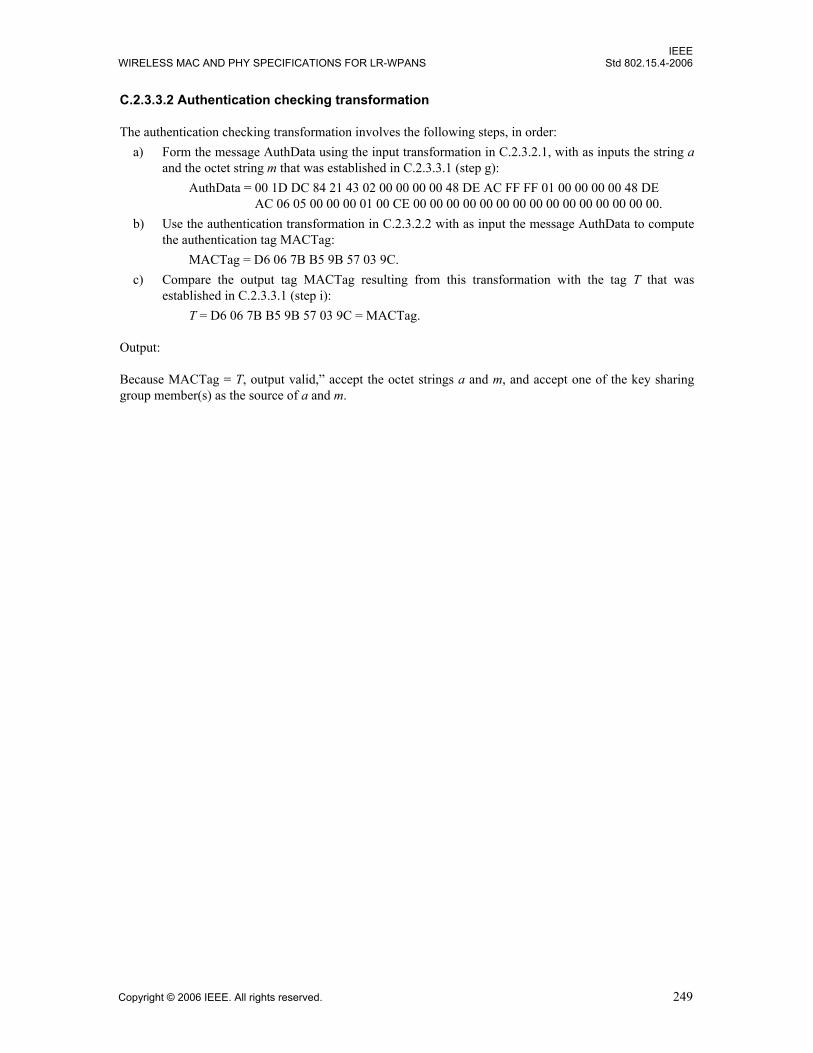
IEEEWIRELESS MAC AND PHY SPECIFICATIONS FOR LR-WPANS Std 802.15.4-2006
C.2.3.3.2 Authentication checking transformation
The authentication checking transformation involves the following steps, in order: a) Form the message AuthData using the input transformation in C.2.3.2.1, with as inputs the string a
and the octet string m that was established in C.2.3.3.1 (step g):AuthData = 00 1D DC 84 21 43 02 00 00 00 00 48 DE AC FF FF 01 00 00 00 00 48 DE
AC 06 05 00 00 00 01 00 CE 00 00 00 00 00 00 00 00 00 00 00 00 00 00 00.b) Use the authentication transformation in C.2.3.2.2 with as input the message AuthData to compute
the authentication tag MACTag:MACTag = D6 06 7B B5 9B 57 03 9C.
c) Compare the output tag MACTag resulting from this transformation with the tag T that wasestablished in C.2.3.3.1 (step i):
T = D6 06 7B B5 9B 57 03 9C = MACTag.
Output:
Because MACTag = T, output valid,” accept the octet strings a and m, and accept one of the key sharinggroup member(s) as the source of a and m.
Copyright © 2006 IEEE. All rights reserved. 249

IEEEStd 802.15.4-2006 LOCAL AND METROPOLITAN AREA NETWORKS—PART 15.4:
250 Copyright © 2006 IEEE. All rights reserved.

IEEEWIRELESS MAC AND PHY SPECIFICATIONS FOR LR-WPANS Std 802.15.4-2006
Annex D
(normative)
Protocol implementation conformance statement (PICS) proforma8
D.1 Introduction
To evaluate conformance of a particular implementation, it is necessary to have a statement of whichcapabilities and options have been implemented for a given standard. Such a statement is called a protocolimplementation conformance statement (PICS).
D.1.1 Scope
This annex provides the PICS proforma for IEEE Std 802.15.4-2006 in compliance with the relevantrequirements, and in accordance with the relevant guidance, given in ISO/IEC 9646-7:1995.
D.1.2 Purpose
The supplier of a protocol implementation claiming to conform to IEEE Std 802.15.4-2006 shall completethe following PICS proforma and accompany it with the information necessary to identify fully both thesupplier and the implementation.
The PICS of a protocol implementation is a statement of which capabilities and options of the protocol havebeen implemented. The statement is in the form of answers to a set of questions in the PICS proforma. Thequestions in a proforma consist of a systematic list of protocol capabilities and options as well as theirimplementation requirements. The implementation requirement indicates whether implementation of acapability is mandatory, optional, or conditional depending on options selected. When a protocolimplementor answers questions in a PICS proforma, the implementor indicates whether an item isimplemented and provides explanations if an item is not implemented.
D.2 Abbreviations and special symbols
Notations for requirement status:
M MandatoryO OptionalO.n Optional, but support of at least one of the group of options labeled O.n is required.N/A Not applicableX Prohibited“item”: Conditional, status dependent upon the support marked for the “item”
For example, FD1: O.1 indicates that the status is optional but at least one of the features described in FD1and FD2 is required to be implemented, if this implementation is to follow the standard to which this PICSproforma is part.
8Copyright release for PICS proformas: Users of this standard may freely reproduce the PICS proforma in this annex so that it can be used for its intended purpose and may further publish the completed PICS.
Copyright © 2006 IEEE. All rights reserved. 251

IEEEStd 802.15.4-2006 LOCAL AND METROPOLITAN AREA NETWORKS—PART 15.4:
D.3 Instructions for completing the PICS proforma
If it is claimed to conform to this standard, the actual PICS proforma to be filled in by a supplier shall betechnically equivalent to the text of the PICS proforma in this annex and shall preserve the numbering,naming, and ordering of the PICS proforma.
A PICS that conforms to this annex shall be a conforming PICS proforma completed in accordance with theinstructions for completion given in this annex.
The main part of the PICS is a fixed-format questionnaire, divided into five tables. Answers to thequestionnaire are to be provided in the rightmost column, either by simply marking an answer to indicate arestricted choice (such as Yes or No) or by entering a value or a set or range of values.
D.4 Identification of the implementation
Implementation under test (IUT) identification
IUT name: _____________________________________________________________________
IUT version: ____________________________________________________________________
______________________________________________________________________________
System under test (SUT) identification
SUT name: _____________________________________________________________________
Hardware configuration: ___________________________________________________________
______________________________________________________________________________
______________________________________________________________________________
Operating system: ________________________________________________________________
Product supplier
Name: ________________________________________________________________________
Address: ______________________________________________________________________
_____________________________________________________________________________
Telephone number: _____________________________________________________________
Facsimile number: ______________________________________________________________
Email address: _________________________________________________________________
Additional information: __________________________________________________________
252 Copyright © 2006 IEEE. All rights reserved.

IEEEWIRELESS MAC AND PHY SPECIFICATIONS FOR LR-WPANS Std 802.15.4-2006
Client
Name: ________________________________________________________________________
Address: ______________________________________________________________________
_____________________________________________________________________________
Telephone number: _____________________________________________________________
Facsimile number: ______________________________________________________________
Email address: ________________________________________________________________
Additional information: __________________________________________________________
PICS contact person
Name: ________________________________________________________________________
Address: ______________________________________________________________________
_____________________________________________________________________________
Telephone number: ______________________________________________________________
Facsimile number: _______________________________________________________________
Email address: _________________________________________________________________
Additional information: ___________________________________________________________
PICS/System conformance statement
Provide the relationship of the PICS with the system conformance statement for the system:______________________________________________________________________________
______________________________________________________________________________
______________________________________________________________________________
D.5 Identification of the protocol
This PICS proforma applies to IEEE Std 802.15.4-2006.
D.6 Global statement of conformance
The implementation described in this PICS proforma meets all of the mandatory requirements of thereferenced standard.
[ ] Yes
[ ] No
Copyright © 2006 IEEE. All rights reserved. 253
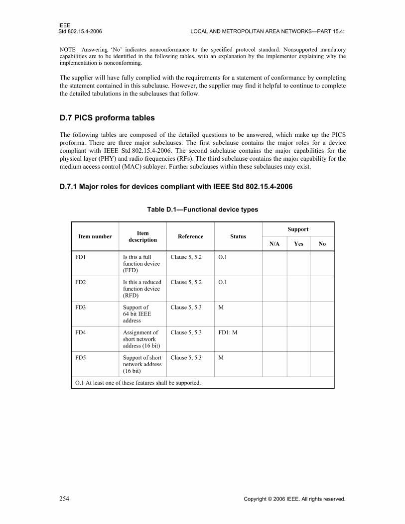
IEEEStd 802.15.4-2006 LOCAL AND METROPOLITAN AREA NETWORKS—PART 15.4:
NOTE—Answering ‘No’ indicates nonconformance to the specified protocol standard. Nonsupported mandatorycapabilities are to be identified in the following tables, with an explanation by the implementor explaining why theimplementation is nonconforming.
The supplier will have fully complied with the requirements for a statement of conformance by completingthe statement contained in this subclause. However, the supplier may find it helpful to continue to completethe detailed tabulations in the subclauses that follow.
D.7 PICS proforma tables
The following tables are composed of the detailed questions to be answered, which make up the PICSproforma. There are three major subclauses. The first subclause contains the major roles for a devicecompliant with IEEE Std 802.15.4-2006. The second subclause contains the major capabilities for thephysical layer (PHY) and radio frequencies (RFs). The third subclause contains the major capability for themedium access control (MAC) sublayer. Further subclauses within these subclauses may exist.
D.7.1 Major roles for devices compliant with IEEE Std 802.15.4-2006
Table D.1—Functional device types
Item number Item description Reference Status
Support
N/A Yes No
FD1 Is this a full function device (FFD)
Clause 5, 5.2 O.1
FD2 Is this a reduced function device (RFD)
Clause 5, 5.2 O.1
FD3 Support of 64 bit IEEE address
Clause 5, 5.3 M
FD4 Assignment of short network address (16 bit)
Clause 5, 5.3 FD1: M
FD5 Support of short network address (16 bit)
Clause 5, 5.3 M
O.1 At least one of these features shall be supported.
254 Copyright © 2006 IEEE. All rights reserved.
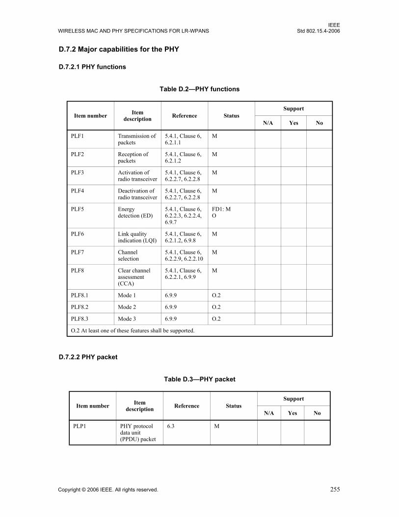
IEEEWIRELESS MAC AND PHY SPECIFICATIONS FOR LR-WPANS Std 802.15.4-2006
D.7.2 Major capabilities for the PHY
D.7.2.1 PHY functions
D.7.2.2 PHY packet
Table D.2—PHY functions
Item number Item description Reference Status
Support
N/A Yes No
PLF1 Transmission of packets
5.4.1, Clause 6, 6.2.1.1
M
PLF2 Reception of packets
5.4.1, Clause 6, 6.2.1.2
M
PLF3 Activation of radio transceiver
5.4.1, Clause 6, 6.2.2.7, 6.2.2.8
M
PLF4 Deactivation of radio transceiver
5.4.1, Clause 6, 6.2.2.7, 6.2.2.8
M
PLF5 Energy detection (ED)
5.4.1, Clause 6, 6.2.2.3, 6.2.2.4, 6.9.7
FD1: MO
PLF6 Link quality indication (LQI)
5.4.1, Clause 6, 6.2.1.2, 6.9.8
M
PLF7 Channel selection
5.4.1, Clause 6, 6.2.2.9, 6.2.2.10
M
PLF8 Clear channel assessment (CCA)
5.4.1, Clause 6, 6.2.2.1, 6.9.9
M
PLF8.1 Mode 1 6.9.9 O.2
PLF8.2 Mode 2 6.9.9 O.2
PLF8.3 Mode 3 6.9.9 O.2
O.2 At least one of these features shall be supported.
Table D.3—PHY packet
Item number Item description Reference Status
Support
N/A Yes No
PLP1 PHY protocol data unit (PPDU) packet
6.3 M
Copyright © 2006 IEEE. All rights reserved. 255
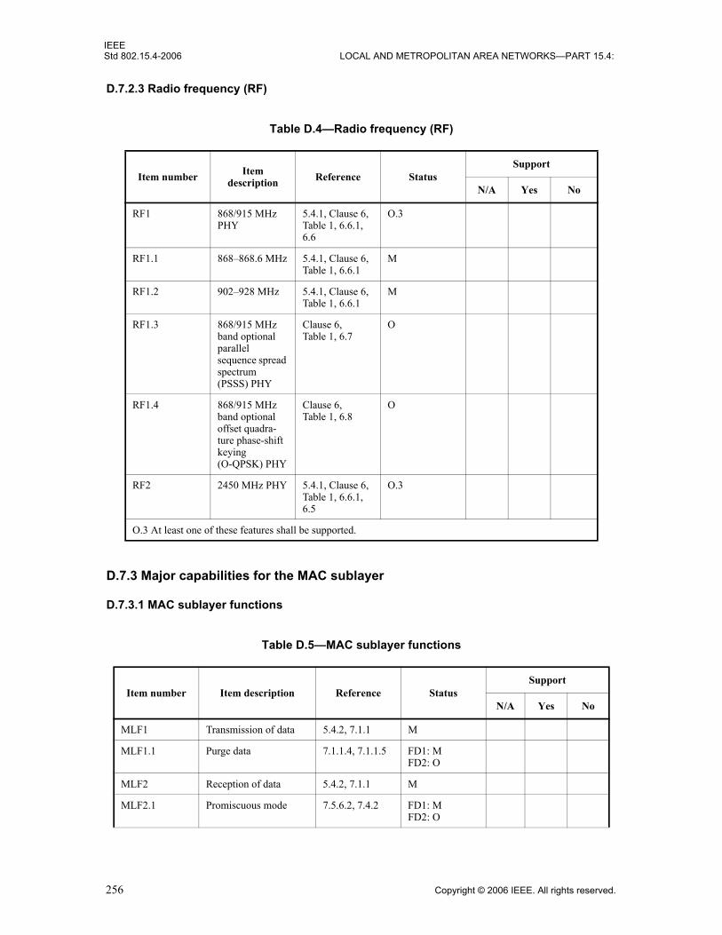
IEEEStd 802.15.4-2006 LOCAL AND METROPOLITAN AREA NETWORKS—PART 15.4:
D.7.2.3 Radio frequency (RF)
D.7.3 Major capabilities for the MAC sublayer
D.7.3.1 MAC sublayer functions
Table D.4—Radio frequency (RF)
Item number Item description Reference Status
Support
N/A Yes No
RF1 868/915 MHz PHY
5.4.1, Clause 6, Table 1, 6.6.1, 6.6
O.3
RF1.1 868–868.6 MHz 5.4.1, Clause 6, Table 1, 6.6.1
M
RF1.2 902–928 MHz 5.4.1, Clause 6, Table 1, 6.6.1
M
RF1.3 868/915 MHz band optional parallel sequence spread spectrum (PSSS) PHY
Clause 6, Table 1, 6.7
O
RF1.4 868/915 MHz band optional offset quadra-ture phase-shift keying (O-QPSK) PHY
Clause 6, Table 1, 6.8
O
RF2 2450 MHz PHY 5.4.1, Clause 6, Table 1, 6.6.1, 6.5
O.3
O.3 At least one of these features shall be supported.
Table D.5—MAC sublayer functions
Item number Item description Reference StatusSupport
N/A Yes No
MLF1 Transmission of data 5.4.2, 7.1.1 M
MLF1.1 Purge data 7.1.1.4, 7.1.1.5 FD1: MFD2: O
MLF2 Reception of data 5.4.2, 7.1.1 M
MLF2.1 Promiscuous mode 7.5.6.2, 7.4.2 FD1: MFD2: O
256 Copyright © 2006 IEEE. All rights reserved.

IEEEWIRELESS MAC AND PHY SPECIFICATIONS FOR LR-WPANS Std 802.15.4-2006
MLF2.2 Control of PHY receiver
7.1.10 O
MLF2.3 Timestamp of incoming data
7.1.1.2 O
MLF3 Beacon management 5.4.2, Clause 7 M
MLF3.1 Transmit beacons 5.4.2, Clause 7, 7.5.2.4
FD1: MFD2: O
MLF3.2 Receive beacons 5.4.2, Clause 7, 7.1.5
M
MLF4 Channel access mechanism
5.4.2, Clause 7, 7.5.1
M
MLF5 Guaranteed time slot (GTS) management
5.4.2, Clause 7, 7.1.7, 7.3.9, 7.5.7
O
MLF5.1 GTS management (allocation)
5.4.2, Clause 7, 7.1.7, 7.3.9, 7.5.7
O
MLF5.2 GTS management (request)
5.4.2, Clause 7, 7.1.7, 7.3.9, 7.5.7
O
MLF6 Frame validation 5.4.2, 5.5.4.3, 7.1.1.3.2, 7.2, 7.5.6.2
M
MLF7 Acknowledged frame delivery
5.4.2, Clause 7, 7.1.1.3.2, 7.2.1.1.4, 7.5.6.4
M
MLF8 Association and disassociation
5.4.2, Clause 7, 7.1.3, 7.1.4, 7.5.3
M
MLF9 Security Clause 7, 7.5.8 M
MLF9.1 Unsecured mode 7.5.8 M
MLF9.2 Secured mode 7.5.8 O
MLF9.2.1 Data encryption 7.5.8 O.4
MLF9.2.2 Frame integrity 7.5.8 O.4
MLF10.1 ED 7.5.2.1, 7.5.2.1.1
FD1: MFD2: O
MLF10.2 Active scanning 7.5.2.1, 7.5.2.1.2
FD1: MFD2: O
MLF10.3 Passive scanning 7.5.2.1, 7.5.2.1.3
M
Table D.5—MAC sublayer functions (continued)
Item number Item description Reference StatusSupport
N/A Yes No
Copyright © 2006 IEEE. All rights reserved. 257

IEEEStd 802.15.4-2006 LOCAL AND METROPOLITAN AREA NETWORKS—PART 15.4:
D.7.3.2 MAC frames
MLF10.4 Orphan scanning 7.5.2.1, 7.5.2.1.4
M
MLF11 Control/define/determine/declare superframe structure
5.5.1, 7.5.1.1 FD1: O
MLF12 Follow/use superframe structure
5.5.1, 7.5.1.1 O
MLF13 Store one transaction 7.5.5 FD1: M
O.4 At least one of these features shall be supported.
Table D.6—MAC frames
Item number Item description Reference
Transmitter Receiver
Status SupportN/A Yes No Status Support
N/A Yes No
MF1 Beacon 5.5.3.1, 7.2.2.1
FD1: M M
MF2 Data 5.5.3.2, 7.2.2.2
M M
MF3 Acknowledgment 5.5.3.3, 7.2.2.3
M M
MF4 Command 5.5.3.4, 7.2.2.4
M M
MF4.1 Association request
5.5.3.4, 7.2.2.4, 7.3.1
M FD1: M
MF4.2 Association response
5.5.3.4, 7.2.2.4, 7.3.2
FD1: M M
MF4.3 Disassociation notification
5.5.3.4, 7.2.2.4, 7.3.3
M M
MF4.4 Data request 5.5.3.4, 7.2.2.4, 7.3.4
M FD1: M
MF4.5 PAN identifier conflict notification
5.5.3.4, 7.2.2.4, 7.3.5
M FD1: M
Table D.5—MAC sublayer functions (continued)
Item number Item description Reference StatusSupport
N/A Yes No
258 Copyright © 2006 IEEE. All rights reserved.
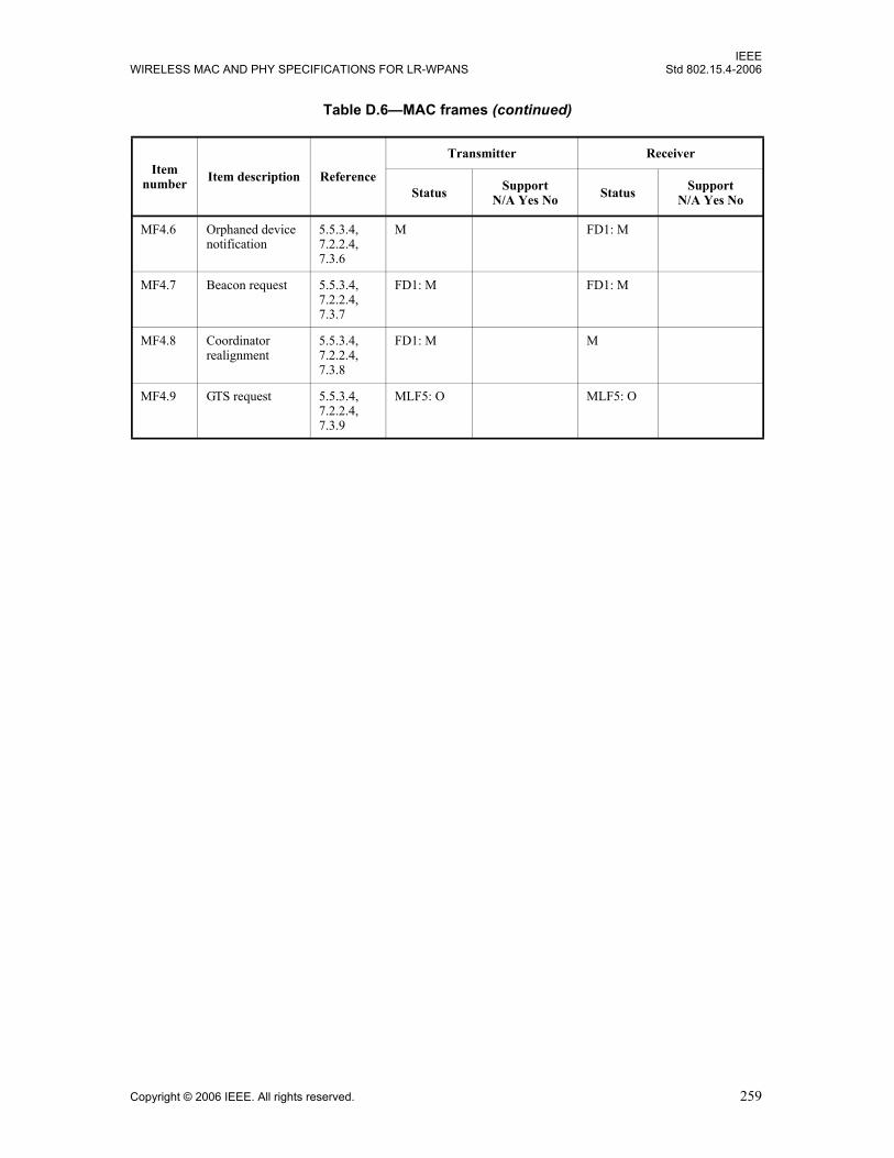
IEEEWIRELESS MAC AND PHY SPECIFICATIONS FOR LR-WPANS Std 802.15.4-2006
MF4.6 Orphaned device notification
5.5.3.4, 7.2.2.4, 7.3.6
M FD1: M
MF4.7 Beacon request 5.5.3.4, 7.2.2.4, 7.3.7
FD1: M FD1: M
MF4.8 Coordinator realignment
5.5.3.4, 7.2.2.4, 7.3.8
FD1: M M
MF4.9 GTS request 5.5.3.4, 7.2.2.4, 7.3.9
MLF5: O MLF5: O
Table D.6—MAC frames (continued)
Item number Item description Reference
Transmitter Receiver
Status SupportN/A Yes No Status Support
N/A Yes No
Copyright © 2006 IEEE. All rights reserved. 259

IEEEStd 802.15.4-2006 LOCAL AND METROPOLITAN AREA NETWORKS—PART 15.4:
260 Copyright © 2006 IEEE. All rights reserved.

IEEEWIRELESS MAC AND PHY SPECIFICATIONS FOR LR-WPANS Std 802.15.4-2006
Annex E
(informative)
Coexistence with other IEEE standards and proposed standards
E.1 Introduction
While not required by this standard, IEEE 802.15.4 devices can be reasonably expected to “coexist,” that is,to operate in proximity to other wireless devices. This annex considers issues regarding coexistence betweenIEEE 802.15.4 devices and other wireless IEEE-compliant devices.
E.2 Standards and proposed standards characterized for coexistence
This clause enumerates IEEE-compliant devices that are characterized and the devices that are notcharacterized for operation in proximity to IEEE 802.15.4 devices.
This standard is specified for operation in the 800 MHz, 900 MHz, and 2400 MHz bands. In the 800/900MHz bands, there are BPSK, O-QPSK, and ASK PHYs, which may interact with each other. In the2400 MHz band, there is only an O-QPSK PHY, which may interact with other IEEE 802 wireless devicesoperating in the 2400 MHz industrial, scientific, and medical (ISM) band.
Standards and proposed standards characterized in this annex for coexistence are as follows:— IEEE Std 802.11b™-1999 [B6] (2400 MHz DSSS)— IEEE Std 802.15.1™-2002 [B8] [2400 MHz frequency hopping spread spectrum (FHSS)]— IEEE Std 802.15.3-2003 [B10] (2400 MHz)
Standards not characterized in this annex for coexistence are as follows:— IEEE Std 802.11™, 1999 Edition [B4], frequency hopping (FH) (2400 MHz FHSS)— IEEE Std 802.11, 1999 Edition [B4], infrared (333 GHz amplitude modulation)— IEEE Std 802.16™-2001 [B11] (2400 MHz OFDM)— IEEE Std 802.11a™-1999 [B5] (5 GHz DSSS)
E.3 General coexistence issues
This standard provides several mechanisms that enhance coexistence with other wireless devices operatingin the 800 MHz, 900 MHz, and 2400 MHz bands. This subclause provides an overview of the mechanismsthat are defined in the standard. These mechanisms include
— CCA— Dynamic channel selection— Modulation— ED and LQI— Low duty cycle— Low transmit power — Channel alignment— Neighbor piconet capability
Copyright © 2006 IEEE. All rights reserved. 261

IEEEStd 802.15.4-2006 LOCAL AND METROPOLITAN AREA NETWORKS—PART 15.4:
These mechanisms are described briefly in E.3.1 through E.3.8.
E.3.1 Clear channel assessment (CCA)
IEEE 802.15.4 PHYs provide the capability to perform CCA in its CSMA-CA mechanism (see 6.9.9). ThePHYs require at least one of the following three CCA methods: ED over a certain threshold, detection of asignal with IEEE 802.15.4 characteristics, or a combination of these methods. Use of the ED optionimproves coexistence by allowing transmission backoff if the channel is occupied by any device, regardlessof the communication protocol it may use.
E.3.2 Modulation
E.3.2.1 2400 MHz band PHY
The 2400 MHz PHY specified for this standard uses a quasi-orthogonal modulation scheme, where eachsymbol is represented by one of 16 nearly orthogonal PN sequences. This is a power-efficient modulationmethod that achieves low signal-to-noise ratio (SNR) and signal-to-interference ratio (SIR) requirements atthe expense of a signal bandwidth that is significantly larger than the symbol rate. A typical low-costdetector implementation is expected to meet the 1% packet error rate (PER) requirement at SNR values of5 dB to 6 dB.
Relatively wideband interference, such as IEEE Std 802.11b-1999 [B6] and IEEE Std 802.15.3-2003 [B10],would appear like white noise to an IEEE 802.15.4 receiver. The detector performance in this case is similarto noise performance, but the overall SIR requirement is 9 dB to 10 dB lower because only a fraction of theIEEE 802.11b or IEEE 802.15.3 signal power falls within the IEEE 802.15.4 receiver bandwidth.
The use of PN sequences to represent each symbol in this standard offers DSSS-like processing gains tointerferers whose bandwidth is smaller than the bandwidth of this standard. For example, this processinggain helps to reduce the impact of an IEEE 802.15.1 interferer, whose 20 dB bandwidth is roughly 50%smaller than the bandwidth of this standard. Whereas the SNR requirement is 5 dB to 6 dB for 1% PER innoise, the equivalent SIR requirement for an IEEE 802.15.1 signal centered within the pass band of theIEEE 802.15.4 receiver is only 2 dB.
In terms of interference to others, this standard appears as wideband interference to IEEE Std 802.15.1-2002[B8], and only a fraction (~50%) of the IEEE 802.15.4 signal power falls within the IEEE 802.15.1 receiverbandwidth. Furthermore, due to the bandwidth ratios and to the frequency hopping used in IEEEStd 802.15.1, IEEE 802.15.4 transmissions will interfere with approximately 3 out of the 79 hops, orapproximately 4%. To an IEEE 802.11b receiver, this standard looks like a narrowband interferer, and theprocessing gain resulting from the spread-spectrum techniques in IEEE Std 802.11b-1999 [B6] will helpreduce the impact of the IEEE 802.15.4 interferer.
E.3.2.2 800/900 MHz band PHYs
The 800/900 MHz band PHYs specified in this standard each use DSSS modulation. These power-efficientmodulation methods achieve low SNR and SIR requirements at the expense of a signal bandwidth that issignificantly larger than the symbol rate. A defining feature of systems that use spread spectrum modulationis that they are less likely to cause interference in other devices due to their reduced PSD. For the samereason, spread spectrum devices have some degree of immunity from interfering emitters, making them agood choice for environments where coexistence is an issue.
262 Copyright © 2006 IEEE. All rights reserved.

IEEEWIRELESS MAC AND PHY SPECIFICATIONS FOR LR-WPANS Std 802.15.4-2006
E.3.3 ED and LQI
The IEEE 802.15.4 PHYs include two measurement functions that indicate the level of interference withinan IEEE 802.15.4 channel. The receiver ED measurement (see 6.9.7) is an estimate of the received signalpower within an IEEE 802.15.4 channel and is intended for use as part of a channel selection algorithm atthe network layer. The LQI (see 6.9.8) measures the received energy level and/or SNR for each receivedpacket. When energy level and SNR data are combined, they can indicate whether a corrupt packet resultedfrom low signal strength or from high signal strength plus interference.
E.3.4 Low duty cycle
The specifications of this standard are tailored for applications with low power and low data rates (amaximum of 250 kb/s and down to 20 kb/s). Typical applications for IEEE 802.15.4 devices are anticipatedto run with low duty cycles (under 1%). This will make IEEE 802.15.4 devices less likely to causeinterference to other standards.
E.3.5 Low transmit power
E.3.5.1 2400 MHz band PHY
Although operation in the 2400 MHz band under Section 15.247 of FCC CFR47 [B29] rules allowtransmission powers up to 1 W, IEEE 802.15.4 devices will likely operate with much lower transmit power.A key metric of IEEE Std 802.15.4-2006 is cost, and achieving greater than 10 dBm transmit power in alow-cost system on chip, while feasible, will be economically disadvantageous. Furthermore, Europeanregulations (ETSI EN 300 328 [B26] and [B27]) for out-of-band emissions make it difficult to transmitabove 10 dBm without additional, expensive filtering. These factors limit the distribution of devices withgreater than 10 dBm transmit power to a few specialized applications.
At the low end, the IEEE 802.15.4 PHY specifies that devices must be capable of at least –3 dBm transmitpower. At this level, actual transmit power represents a small fraction of the overall power consumed by thetransmitter, so there is little benefit in terms of energy savings to operate below this level. However, thisstandard does encourage operating with lower transmit power, when possible, to minimize interference (see6.9.5).
Thus the majority of IEEE 802.15.4 devices are expected to operate with transmit powers between –3 dBmand 10 dBm, with 0 dBm being typical. IEEE 802.11b devices also operate under Section 15.247 of FCCCFR47 [B29], where up to 1 W of transmit power is allowed; however, most devices in the market todayoperate at transmit powers between 12 dBm and 18 dBm. IEEE 802.15.3 devices operate under Section15.249 of FCC CFR47, which limits transmit power to 8 dBm EIRP. The EIRP measurement for theIEEE 802.15.3 PHY includes the antenna gain; therefore, a 1 dB increase antenna gain requires a 1 dBdecrease in transmit power. In contrast, devices operating under Section 15.247 of FCC CFR47 are allowedup to 6 dB of antenna gain without modifications to the transmit power.
Assuming moderate antenna gain (~0 dBi) for typical implementations, the discussion in this subclauseimplies that a nominal IEEE 802.15.4 transmitter would operate about 8 dB less than the IEEE 802.15.3transmitter and about 12 dB to 18 dB less than a typical IEEE 802.11b implementation.
E.3.5.2 800 MHz band PHYs
Regulations defined by ERC Recommendation 70-03 [B24] and ETSI EN 300 220-1 [B25] limit transmitterpower in the 868 MHz to 25mW (13.9 dBm) maximum. Although devices conforming to IEEEStd 802.15.4-2006 may transmit at this power, the economics of system-on-chip designs will limit the
Copyright © 2006 IEEE. All rights reserved. 263

IEEEStd 802.15.4-2006 LOCAL AND METROPOLITAN AREA NETWORKS—PART 15.4:
transmit power to around 10 dBm. At the low end, all confirming devices must be capable of at least –3 dBmtransmit power. At this power, the transmit power represents a small fraction of the overall power consumedby the device; therefore, there is no significant energy savings for operating below this level. However, thisstandard does encourage operating with lower power, when possible, in order to minimize interference.
Consequently, it is reasonable to assume that all 868 MHz devices will transmit at a power between –3 dBmand +10 dBm.
E.3.5.3 900 MHz band PHYs
Regulations defined by FCC CFR47 [B29] limit transmitter power in the 868 MHz to 1000mW (30 dBm)maximum. Although devices conforming to IEEE Std 802.15.4-2006 may transmit at this power, theeconomics of system-on-chip designs will limit the transmit power to around 10 dBm. At the low end, allconfirming devices must be capable of at least –3 dBm transmit power. At this power, the transmit powerrepresents a small fraction of the overall power consumed by the device; therefore, there is no significantenergy savings for operating below this level. However, this standard does encourage operating with lowerpower, when possible, in order to minimize interference.
E.3.6 Channel alignment
The alignment between IEEE 802.11b (nonoverlapping sets) and IEEE 802.15.4 2400 MHz band channels isshown in Figure E.1. There are four IEEE 802.15.4 channels that fall in the guard bands between (or above)the three IEEE 802.11b channels (n = 15, 20, 25, 26 for North America; n = 15, 16, 21, 22 in Europe). Whilethe energy in this guard space will not be zero, it will be lower than the energy within the channels; andoperating an IEEE 802.15.4 network on one of these channels will minimize interference between systems.
E.3.7 Dynamic channel selection
When performing dynamic channel selection, either at network initialization or in response to an outage, anIEEE 802.15.4 device will scan a set of channels specified by the ChannelList parameter. For 2400 MHzband IEEE 802.15.4 networks that are installed in areas known to have high IEEE 802.11b activity, theChannelList parameter can be defined as the above sets in order to enhance the coexistence of the networks.For 915 MHz IEEE 802.15.4 networks that are installed in areas known to have interference from knownsources, the ChannelList parameter can be defined as the above sets in order to enhance the coexistence ofthe networks.
E.3.8 Neighbor piconet capability
Interoperability with other systems is beyond the scope of this standard. However, certain schemes may beenvisaged for this purpose, for example, the PAN coordinator can set aside GTSs specifically for use byother systems. This type of neighbor piconet support capability may further alleviate interference with othersystems.
264 Copyright © 2006 IEEE. All rights reserved.

IEEEWIRELESS MAC AND PHY SPECIFICATIONS FOR LR-WPANS Std 802.15.4-2006
E.4 2400 MHz band coexistence performance
The assumptions made across all standards characterized for coexistence are described in E.4.1. SubclausesE.4.2 and E.4.3 describe the assumptions made for individual standards and quantify their predictedperformance when coexisting with IEEE 802.15.4 devices.
E.4.1 Assumptions for coexistence quantification
The assumptions in E.4.1.1 through E.4.1.9 are made to determine the level of coexistence.
E.4.1.1 Channel model
The channel model is based on IEEE Std 802.11 as adapted by IEEE Std 802.15.2™-2003 [B9] and IEEEStd 802.15.3-2003 [B10]:
2400 MHz 2412 MHz 2437 MHz 2462 MHz 2483.5 MHz
Channel 1 Channel 6 Channel 11
22 MHz
2400 MHz 2412 MHz 2442 MHz 2472 MHz 2483.5 MHz
Channel 1 Channel 7 Channel 13
22 MHz
2400 MHz
2410
2483.5 MHz
Channel 11 12
2 MHz
13 14 15 16 17 18 19 20 21 22 23 24 25 26
2415 2420 2425 2405 2430 2435 2440 2445 2450 2455 2460 2465 2470 2475 2480
b) IEEE 802.11b European channel selection (nonoverlapping)
Figure E.1—IEEE 802.15.4 (2400 MHz PHY) and IEEE 802.11b channel selection
a) IEEE 802.11b North American channel selection (nonoverlapping)
c) IEEE 802.15.4 channel selection (2400 MHz PHY)
Copyright © 2006 IEEE. All rights reserved. 265

IEEEStd 802.15.4-2006 LOCAL AND METROPOLITAN AREA NETWORKS—PART 15.4:
for d < 8m
for d > 8 m
E.4.1.2 Receiver sensitivity
The receiver sensitivity assumed is the reference sensitivity specified in each standards as follows:a) –76 dBm for IEEE 802.11b 11 Mb/s CCKb) –70 dBm for IEEE Std 802.15.1-2002 [B8]c) –75 dBm for IEEE 802.15.3 22 Mb/s DQPSKd) –85 dBm for this standard
E.4.1.3 Transmit power
The transmitter power for each coexisting standard has been specified as follows:a) 14 dBm for IEEE Std 802.11b-1999 [B6]b) 0 dBm for IEEE Std 802.15.1-2002 [B8]c) 8 dBm for IEEE Std 802.15.3-2003 [B10]d) 0 dBm for this standard
E.4.1.4 Receiver bandwidth
The receiver bandwidth is as required by each standard as follows: a) 22 MHz for IEEE Std 802.11b-1999 [B6]b) 1 MHz for IEEE Std 802.15.1-2002 [B8]c) 15 MHz for IEEE Std 802.15.3-2003 [B10]d) 2 MHz for this standard
E.4.1.5 Transmit spectral masks
The maximum transmitter spectral masks are assumed for the calculations. This assumption is the absoluteworst-case scenario; in most cases, the transmitter spectrum will be lower. See Table E.1 throughTable E.4.
Table E.1—Transmit mask for IEEE Std 802.11b-1999 [B6] (see 18.4.7.3 in that standard)
Frequency Relative limit
fc – 22 MHz < f < fc – 11 MHz andfc + 11 MHz < f < fc + 22 MHz
–30 dBr
f < fc – 22 MHz andf > fc + 22 MHz
–50 dBr
d 10Pt Pr– 40.2–( )
20--------------------------------------
=
d 8 10Pt Pr– 58.5–( )
33--------------------------------------×=
266 Copyright © 2006 IEEE. All rights reserved.

IEEEWIRELESS MAC AND PHY SPECIFICATIONS FOR LR-WPANS Std 802.15.4-2006
E.4.1.6 IEEE 802.11b transmit PSD
Because IEEE 802.11 implementations will generally meet FCC requirements, they will achieve an absolutepower of less than –41.3 dBm/MHz at a separation of 22 MHz from the carrier frequency. The reason forthis is that there is a restricted band that ends at 2.39 GHz, which is 22 MHz from the center of the lowestchannel used for the FCC regulatory domain (see 18.4.6.2 in FCC CFR47 [B29]). Thus, the relative powerfor greater than 22 MHz separation would be +14 dBm – (–41.3 dBm) = 55.3 dB.
E.4.1.7 Interference characteristics
The effect of the interfering signal on the desired signal is assumed to be similar to additive white Gaussiannoise (AWGN) in the same bandwidth.
E.4.1.8 Bit error rate (BER) calculations
The BER calculations are as described in 5.3 of IEEE Std 802.15.2-2003 [B9]:
1) BER for IEEE Std 802.11b-1999 [B6] at 1 Mb/s =
2) BER for IEEE Std 802.11b at 2 Mb/s =
Table E.2—Transmit mask for IEEE Std 802.15.1-2002 [B8] (see 7.2.3.1 in that standard)
Frequency offset Transmit power
± 500 kHz –20 dBc
|M – N| = 2 –20 dBm
|M – N| ≥ 3 –40 dBm
The transmitter is transmitting on channel M, and the adjacent channel power is measured on channel number N.
Table E.3—Transmit mask for IEEE Std 802.15.3-2003 [B10] (see 11.5.3 in that standard)
Frequency offset Relative limit
7.5 MHz < | f – fc | < 15 MHz –30 dBr
15 MHz < | f – fc | < 22 MHz –1 /7[ | f – fc (MHz)| + 13] dBr
22 MHz < | f – fc | –50 dBr
Table E.4—Transmit mask for this standard (see 6.5.3.1)
Frequency Relative limit Absolute limit
| f – fc | >3.5 MHz –20 dBr –30 dBm
Q 11 SINR×( )12---
Q 5.5 SINR2-------------×⎝ ⎠
⎛ ⎞12---
Copyright © 2006 IEEE. All rights reserved. 267

IEEEStd 802.15.4-2006 LOCAL AND METROPOLITAN AREA NETWORKS—PART 15.4:
3) BER for IEEE Std 802.11b at 5.5 Mb/s =
4) BER for IEEE Std 802.11b at 11 Mb/s =
5) BER for IEEE Std 802.15.1-2002 [B8] =
6) BER for IEEE Std 802.15.3-2003 [B10] at 11 Mb/s =
7) BER for this standard =
E.4.1.9 Packet error rate (PER)
To convert between BER and PER, the following average packet lengths are assumed: a) Average frame for IEEE Std 802.11b-1999 [B6] = 1024 bytesb) Average frame for IEEE Std 802.15.1-2002 [B8] = 1024 bytesc) Average frame length for IEEE Std 802.15.3-2003 [B10] = 1024 bytesd) Average frame length for this standard = 22 bytes
E.4.2 BER model
This subclause presents the BER for standards characterized for coexistence. The BER results were obtainedusing the analytical model from IEEE Std 802.15.2-2003 [B9]. The calculation follows the approachoutlined in 5.3.2 of that standard, and the conversion from SNR to BER uses the formulas in 5.3.6 of thatstandard. Figure E.2 illustrates the relationship between BER and SNR for IEEE Std 802.11b-1999 [B6],IEEE 802.15.3 base rate, IEEE Std 802.15.1-2002 [B8], and this standard.
E.4.3 Coexistence simulation results
Using the assumptions outlined in E.4.2, an analytical simulation tool was developed to quantify the effectof interference between neighboring devices. For each of the cases studied, the receiver under test waspresented with a desired signal at 10 dB above the required sensitivity (see E.4.1.2) and a single interferingdevice with appropriate transmit power (see E.4.1.3). The amount of received interference power wasdetermined using the propagation model (see E.4.1.1) as well as the transmit PSD (see E.4.1.5) and receiverbandwidth (E.4.1.4), and the resulting SIR level was used to estimate the achievable PER.
815------ 14 Q 8 SINR×( )
12--- Q 16 SINR×( )
12---+×
⎝ ⎠⎜ ⎟⎛ ⎞
×
128255--------- 24 Q 4 SINR×( )
12--- 16 Q 16 SINR×( )
12---×+× 174 Q 8 SINR×( )
12---×+
⎝⎜⎛
× …
16 Q 10 SINR×( )12---× 24+ Q 12 SINR×( )
12--- Q 16 SINR×( )
12---+×⎠⎟⎞
0.5 eSINR–
2-----------------×
Q SINR12---
⎝ ⎠⎜ ⎟⎛ ⎞
815------ 1
16------× 1k 16k⎝ ⎠
⎛ ⎞–k 2=
16
∑× e20 SINR 1
k--- 1–⎝ ⎠⎛ ⎞××⎝ ⎠
⎛ ⎞
268 Copyright © 2006 IEEE. All rights reserved.

IEEEWIRELESS MAC AND PHY SPECIFICATIONS FOR LR-WPANS Std 802.15.4-2006
The simulation output (see Figure E.3 through Figure E.8) shows the PER versus separation distance andfrequency offset for various combinations of devices. When comparing the results, some obvious featuresstand out. First, for the nonhopping systems, large frequency offsets allow close-proximity coexistence (lessthan 2 m separation), while low-frequency offsets, or co-channel interference, require separation distances inthe tens of meters. Therefore, as expected, the ability to detect channel occupancy and perform dynamicchannel selection is an important mechanism for coexistence.
A second observation is that transmit power level is the dominant factor in co-channel interferencesituations. When a low-power IEEE 802.15.4 device is moved toward an IEEE 802.11b or IEEE 802.15.3device, the IEEE 802.15.4 device is the first to degrade. IEEE Std 802.15.1-2002 [B8] and this standardhave similar transmit powers, and their interference effects on each other are similar.
Even with its low transmit power level, the results presented here suggest that an IEEE 802.15.4 device cancause degradation to the other devices in co-channel situations with separation distances below 20 m.However, in practice, several IEEE 802.15.4 coexistence features (which were not included in this PHYsimulation) will help to further reduce the occurrence and severity of co-channel interference. These includethe very low duty cycle operation for typical IEEE 802.15.4 applications, as well as the use of CCA prior totransmission (CSMA-CA).
Figure E.2—BER results for IEEE Std 802.11b, IEEE Std 802.15.1, IEEE Std 802.15.3, and this standard
1.0E-09
1.0E-08
1.0E-07
1.0E-06
1.0E-05
1.0E-04
1.0E-03
1.0E-02
1.0E-01
1.0E+00
-10 -5 0 5 10 15
SNR (dB)
Bit
Erro
r Rat
e
802.11b (11M bps)802.11b (5.5M bps)802.11b (2M bps)802.11b (1M bps)802.15.1802.15.3 (22M bps)802.15.4
Copyright © 2006 IEEE. All rights reserved. 269

IEEEStd 802.15.4-2006 LOCAL AND METROPOLITAN AREA NETWORKS—PART 15.4:
Figure E.3—IEEE 802.15.4 receiver, IEEE 802.11b interferer
1.0E-06
1.0E-05
1.0E-04
1.0E-03
1.0E-02
1.0E-01
1.0E+00
0.1 1 10 100
Separation (m)
Pack
et E
rror
Rat
e
Foffset=3.0MHz
Foffset=22.0MHz
Foffset=47.0MHz
Figure E.4—IEEE 802.11b receiver, IEEE 802.15.4 interferer
1.0E-06
1.0E-05
1.0E-04
1.0E-03
1.0E-02
1.0E-01
1.0E+00
0.1 1 10 100
Separation (m)
Pack
et E
rror
Rat
e
Rcvr=802.11b(11M bps)Foffset=3.0M HzRcvr=802.11b(5.5M bps)Foffset=3.0M HzRcvr=802.11b(2M bps)Foffset=3.0M HzRcvr=802.11b(1M bps)Foffset=3.0M HzRcvr=802.11b(11M bps)Foffset=22.0M HzRcvr=802.11b(5.5M bps)Foffset=22.0M HzRcvr=802.11b(2M bps)Foffset=22.0M HzRcvr=802.11b(1M bps)Foffset=22.0M HzRcvr=802.11b(11M bps)Foffset=47.0M HzRcvr=802.11b(5.5M bps)Foffset=47.0M HzRcvr=802.11b(2M bps)Foffset=47.0M HzRcvr=802.11b(1M bps)Foffset=47.0M Hz
270 Copyright © 2006 IEEE. All rights reserved.

IEEEWIRELESS MAC AND PHY SPECIFICATIONS FOR LR-WPANS Std 802.15.4-2006
Figure E.5—IEEE 802.15.4 receiver, IEEE 802.15.1 interferer
1.0E-06
1.0E-05
1.0E-04
1.0E-03
1.0E-02
1.0E-01
1.0E+00
0.01 0.1 1 10 100
Separation (m)
Erro
r Rat
e
Bit Error Rate
Packet Error Rate
Figure E.6—IEEE 802.15.1 receiver, IEEE 802.15.4 interferer
1.0E-06
1.0E-05
1.0E-04
1.0E-03
1.0E-02
1.0E-01
1.0E+00
0.01 0.1 1 10 100
Separation (m)
Erro
r Rat
e
Bit Error Rate
Packet Error Rate
Copyright © 2006 IEEE. All rights reserved. 271

IEEEStd 802.15.4-2006 LOCAL AND METROPOLITAN AREA NETWORKS—PART 15.4:
Figure E.7—IEEE 802.15.4 receiver, IEEE 802.15.3 interferer
1.0E-06
1.0E-05
1.0E-04
1.0E-03
1.0E-02
1.0E-01
1.0E+00
0.1 1 10 100
Separation (m)
Pack
et E
rror
Rat
e
Foffset=2.0MHz
Foffset=17.0MHz
Foffset=27.0MHz
Figure E.8—IEEE 802.15.3 receiver, IEEE 802.15.4 interferer
1.0E-06
1.0E-05
1.0E-04
1.0E-03
1.0E-02
1.0E-01
1.0E+00
0.1 1 10 100
Separation (m)
Pack
et E
rror
Rat
e
Foffset=2.0MHz
Foffset=17.0MHz
Foffset=27.0MHz
272 Copyright © 2006 IEEE. All rights reserved.
IEEEWIRELESS MAC AND PHY SPECIFICATIONS FOR LR-WPANS Std 802.15.4-2006
E.5 800/900 MHz bands coexistence performance
In order to quantify the coexistence performance of the IEEE 802.15.4 PHYs operating below 1 GHz, thetechniques described in Shellhammer [B19] and [B20] have been adopted.
The coexistence assurance methodology predicts the PER of an affected wireless network (AWN, or victim)in the presence of an interfering wireless network (IWN, or assailant). In its simplest form, the methodologyassumes an AWN and an IWN, each composed of a single transmitter and a receiver. The methodologytakes as input a path loss model, a BER function for the AWN, and predicted temporal models for packetsgenerated by the AWN and for “pulses,” i.e., packets generated by the IWN. Based on these inputs, themethodology predicts the PER of the AWN as a function of the physical spacing between the IWNtransmitter and the AWN receiver.
The appeal of the coexistence assurance methodology is that multiple networking standards can becharacterized and compared with just a few parameters, notably
— Bandwidth of AWN and IWN devices— Path loss model for the networks— BER as a function of SIR of AWN devices9
Subclauses E.5.1 through E.5.4 describe the general assumptions made across all six sub-gigahertz PHYs.
E.5.1 Victims and assailants
At present, the six PHYs described in this standard are the only wireless networking standards in the868 MHz and 915 MHz bands covered under IEEE 802. Because other wireless systems are notcharacterized here, it is assumed that the PHYs will serve as both victims (participants in AWNs) and asassailants (participants in IWNs).
E.5.2 Bandwidth
The three IEEE 802.15.4 PHYs that operate in the 868 MHz band have one channel, approximately 600 kHzwide. The coexistence methodology assumes that any 868 MHz device in an AWN will have the samebandwidth as a device in the IWN.
Similarly, the three PHYs that operate in the 915 MHz band have 10 channels, each one 2 MHz wide. Thecoexistence methodology assumes that any 915 MHz device in an AWN will be operating in the samechannel and have the same bandwidth as a device in the IWN.
E.5.3 Path loss model
The coexistence methodology uses a variant of the path loss model described in IEEE Std 802.15.2-2003[B9], which stipulates a two-segment function with a path loss exponent of 2.0 for the first 8 m and then apath loss exponent of 3.3 thereafter. The formula given in IEEE Std 802.15.2 is shown in Equation (E.1).
9Although the methodology described in Stellhammer [B19] uses symbol error rate (SER) to characterize PHY performance, BER hasbeen used in this standard instead because available error functions are more commonly defined as BER rather than SER.
Copyright © 2006 IEEE. All rights reserved. 273

IEEEStd 802.15.4-2006 LOCAL AND METROPOLITAN AREA NETWORKS—PART 15.4:
(E.1)
The constants in this formula are based on a 2400 MHz center frequency. To adapt the model to a 900 MHzcenter frequency, Equation (E.1) can be generalized as shown in Equation (E.2).
(E.2)
wherepl(1) is the path loss at 1 m (in dB)1 is the path loss exponent at 1 m (2.0)8 is the path loss exponent at 8 m (3.3)
The initial condition of pl(1) is computed as shown in Equation (E.3).
(E.3)
With γ1 = 2.0, f = 900 MHz, and C = speedoflight = 299792458 ms–1, pl(1) = 31.53 and pl(8) = 49.59 arecomputed. The path loss function modified for 900 MHz is, therefore, as shown in Equation (E.4).
(E.4)
A plot of the path loss function is shown in Figure E.9.
E.5.4 Temporal model
In this standard, packet overhead is kept to minimum. The maximum PSDU size is 128 bytes, and a typicalpacket may be only 32 bytes, including PSDU and synchronization bytes. For the coexistence methodology,all packets, whether belonging to the AWN or IWN, are assumed to be 32 bytes.
As specified in ERC Recommendation 70-03 [B24] and ETSI EN 300 220-1 [B25], the 868 MHz ISM bandis limited by European regulations to operate at or under 1% duty cycle. Therefore, all 868 MHz BPSKdevices, whether operating in AWNs or IWNs, can be assumed to be operating at 1% worst case.
Although there are no duty cycle limitations in the 915 MHz band, many networks based on this standard areexpected to operate at well under 1% duty cycle, particularly devices that are battery powered. It isreasonable to expect that mains-powered devices, such as PAN coordinators and data aggregation points,may operate at duty cycles as high as 10%. For purposes of modeling coexistence, it is assumed that all915 MHz devices, whether operating in AWNs or IWNs, have a duty cycle of 10%.
pl d( )40.2 20log10 d( )+ d 8m≤
58.5 33log10d8---⎝ ⎠⎛ ⎞+ d 8m>
⎩⎪⎨⎪⎧
=
pl d( )pl 1( ) 10γ1log10 d( )+ d 8m≤
pl 8( ) 10γ8log10d8---⎝ ⎠⎛ ⎞+ d 8m>
⎩⎪⎨⎪⎧
=
pl 1( ) 10γ1log104πfC
--------⎝ ⎠⎛ ⎞=
pl d( )31.53 20log10 d( )+ d 8m≤
49.59 33log10d8---⎝ ⎠⎛ ⎞+ d 8m>
⎩⎪⎨⎪⎧
=
274 Copyright © 2006 IEEE. All rights reserved.

IEEEWIRELESS MAC AND PHY SPECIFICATIONS FOR LR-WPANS Std 802.15.4-2006
E.5.5 Coexistence assurance results
This subclause describes the parameters that are particular to each PHY covered under this standard andshows the results of the coexistence assurance methodology for each of the sub-gigahertz PHYs.
E.5.5.1 868 MHz BPSK PHY
E.5.5.1.1 BER as a function of SIR
IEEE 802.15.4 868 MHz BPSK modulation uses a chip rate Rc of 300 kc/s and a bit rate Rb of 20 kb/s.Conversion from SNR to Eb/N0 assumes a raised cosine filter as shown in Equation (E.5).
(E.5)
BER Pb is computed for noncoherent BPSK, e.g., from Sklar [B21], as shown in Equation (E.6).
(E.6)
Rolling these together produces the BER function as shown in Equation (E.7).
(E.7)
Path Loss Function
30
40
50
60
70
80
1 10 100
Distance (meters)
Figure E.9—Plot of path loss function for 900 MHz
Eb
N0------
0.75Rc
Rb----------------SNR 0.75 300000×
20000----------------------------------SNR 11.25SNR= = =
Pb 0.5Eb
N0------–⎝ ⎠
⎛ ⎞exp=
Pb 0.5 11.25SNR–( )exp=
Copyright © 2006 IEEE. All rights reserved. 275
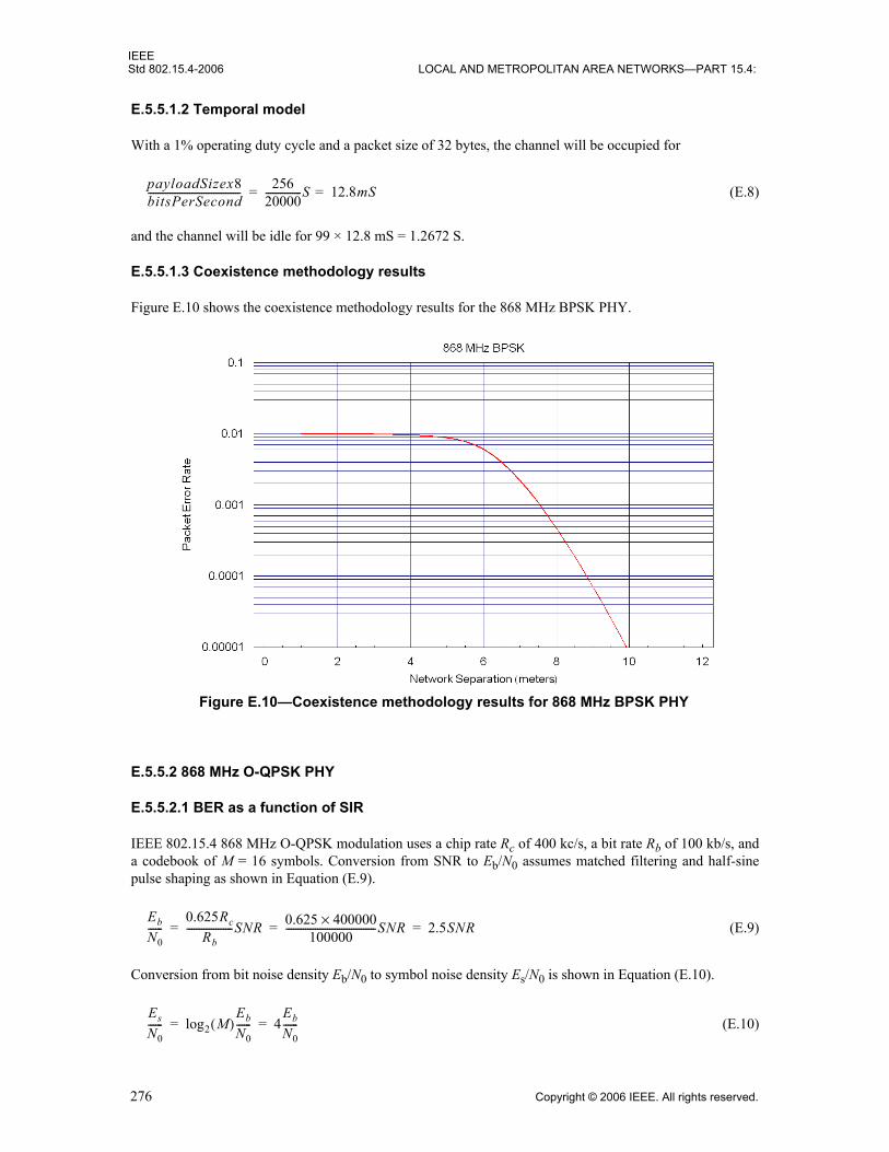
IEEEStd 802.15.4-2006 LOCAL AND METROPOLITAN AREA NETWORKS—PART 15.4:
E.5.5.1.2 Temporal model
With a 1% operating duty cycle and a packet size of 32 bytes, the channel will be occupied for
(E.8)
and the channel will be idle for 99 × 12.8 mS = 1.2672 S.
E.5.5.1.3 Coexistence methodology results
Figure E.10 shows the coexistence methodology results for the 868 MHz BPSK PHY.
E.5.5.2 868 MHz O-QPSK PHY
E.5.5.2.1 BER as a function of SIR
IEEE 802.15.4 868 MHz O-QPSK modulation uses a chip rate Rc of 400 kc/s, a bit rate Rb of 100 kb/s, anda codebook of M = 16 symbols. Conversion from SNR to Eb/N0 assumes matched filtering and half-sinepulse shaping as shown in Equation (E.9).
(E.9)
Conversion from bit noise density Eb/N0 to symbol noise density Es/N0 is shown in Equation (E.10).
(E.10)
payloadSizex8bitsPerSecond-------------------------------------- 256
20000---------------S 12.8mS==
Figure E.10—Coexistence methodology results for 868 MHz BPSK PHY
Eb
N0------
0.625Rc
Rb-------------------SNR 0.625 400000×
100000-------------------------------------SNR 2.5SNR= = =
Es
N0------ log2 M( )
Eb
N0------ 4
Eb
N0------= =
276 Copyright © 2006 IEEE. All rights reserved.

IEEEWIRELESS MAC AND PHY SPECIFICATIONS FOR LR-WPANS Std 802.15.4-2006
Symbol error rate (SER) Ps is computed for noncoherent MFSK, e.g., from Sklar [B21], as shown inEquation (E.11).
(E.11)
Finally, conversion from SER Ps to BER Pb is given as shown in Equation (E.12).
(E.12)
Rolling these together produces the BER function as shown in Equation (E.13).
(E.13)
E.5.5.2.2 Temporal model
With a 1% operating duty cycle and a packet size of 32 bytes, the channel will be occupied for
(E.14)
and the channel will be idle for 99 × 2.56 mS = 253.44 mS.
E.5.5.2.3 Coexistence methodology results
Figure E.11 shows the coexistence methodology results for the 868 MHz O-QPSK PHY.
Ps1M----- 1–( )j M
j⎝ ⎠⎛ ⎞ Es
N0------ 1
j--- 1–⎝ ⎠⎛ ⎞
⎝ ⎠⎛ ⎞exp
j 2=
M
∑=
Pb PsM 2⁄M 1–--------------⎝ ⎠⎛ ⎞ Ps
815------⎝ ⎠⎛ ⎞= =
Pb8
15------⎝ ⎠⎛ ⎞ 1
16------⎝ ⎠⎛ ⎞ 1–( )j 16
j⎝ ⎠⎛ ⎞ 10SNR 1
j--- 1–⎝ ⎠⎛ ⎞
⎝ ⎠⎛ ⎞exp
j 2=
M
∑=
payloadSizex8bitsPerSecond-------------------------------------- 256
100000------------------S 2.56mS==
Figure E.11—Coexistence methodology results for 868 MHz O-QPSK PHY
Copyright © 2006 IEEE. All rights reserved. 277

IEEEStd 802.15.4-2006 LOCAL AND METROPOLITAN AREA NETWORKS—PART 15.4:
E.5.5.3 868 MHz PSSS PHY
E.5.5.3.1 BER as a function of SIR
IEEE 802.15.4 868 MHz PSSS uses a form of ASK modulation, for which the BER function is most easilyderived by simulation and curve fitting. For SNR values greater than –8 dB, the BER function isapproximated as shown in Equation (E.15).
(E.15)
E.5.5.3.2 Temporal model
With a 1% operating duty cycle and a packet size of 32 bytes, the channel will be occupied for
(E.16)
and the channel will be idle for 99 × 1.024 mS = 101.376 mS.
E.5.5.3.3 Coexistence methodology results
Figure E.12 shows the coexistence methodology results for the 868 MHz PSSS PHY.
Pb 0.4146 6.0871SNR–( )exp=
payloadSizex8bitsPerSecond-------------------------------------- 256
250000------------------S 1.024mS==
Figure E.12—Coexistence methodology results for 868 MHz PSSS PHY
278 Copyright © 2006 IEEE. All rights reserved.

IEEEWIRELESS MAC AND PHY SPECIFICATIONS FOR LR-WPANS Std 802.15.4-2006
E.5.5.4 915 MHz BPSK PHY
E.5.5.4.1 BER as a function of SIR
IEEE 802.15.4 915 MHz BPSK modulation uses a chip rate Rc of 600 kc/s and a bit rate Rb of 40 kb/s.Conversion from SNR to Eb/N0 assumes a raised cosine filter as shown in Equation (E.17).
(E.17)
BER Pb is computed for noncoherent BPSK, e.g., from Sklar [B21], as shown in Equation (E.18).
(E.18)
Rolling these together produces the BER function as shown in Equation (E.19).
(E.19)
E.5.5.4.2 Temporal model
With a 10% operating duty cycle and a packet size of 32 bytes, the channel will be occupied for
(E.20)
and the channel will be idle for 90 × 6.4 mS = 576 mS.
E.5.5.4.3 Coexistence methodology results
Figure E.13 shows the coexistence methodology results for the 915 MHz BPSK PHY.
Eb
N0------
0.75Rc
Rb----------------SNR 0.75 600000×
40000----------------------------------SNR 11.25SNR= = =
Pb 0.5Eb
N0------–⎝ ⎠
⎛ ⎞exp=
Pb 0.5 11.25SNR–( )exp=
payloadSizex8bitsPerSecond-------------------------------------- 256
40000---------------S 6.4mS==
Figure E.13—Coexistence methodology results for 915 MHz BPSK PHY
Copyright © 2006 IEEE. All rights reserved. 279

IEEEStd 802.15.4-2006 LOCAL AND METROPOLITAN AREA NETWORKS—PART 15.4:
E.5.5.5 915 MHz O-QPSK PHY
E.5.5.5.1 BER as a function of SIR
IEEE 802.15.4 915 MHz O-QPSK modulation uses a chip rate Rc of 1000 kc/s, a bit rate Rb of 250 kb/s, anda codebook of M = 16 symbols. Conversion from SNR to Eb/N0 assumes matched filtering and half-sinepulse shaping as shown in Equation (E.21).
(E.21)
Conversion from bit noise density Eb/N0 to symbol noise density Es/N0 is shown in Equation (E.22).
(E.22)
SER Ps is computed for noncoherent MFSK, e.g., from Sklar [B21], as shown in Equation (E.23).
(E.23)
Finally, conversion from SER Ps to BER Pb is given as shown in Equation (E.24).
(E.24)
Rolling these together produces the BER function as shown in Equation (E.25).
(E.25)
E.5.5.5.2 Temporal model
With a 10% operating duty cycle and a packet size of 32 bytes, the channel will be occupied for
(E.26)
and the channel will be idle for 90 × 1.024 mS = 92.16 mS.
Eb
N0------
0.625Rc
Rb-------------------SNR 0.625 1000000×
250000----------------------------------------SNR 2.5SNR= = =
Es
N0------ log2 M( )
Eb
N0------ 4
Eb
N0------= =
Ps1M----- 1–( )j M
j⎝ ⎠⎛ ⎞ Es
N0------ 1
j--- 1–⎝ ⎠⎛ ⎞
⎝ ⎠⎛ ⎞exp
j 2=
M
∑=
Pb PsM 2⁄M 1–--------------⎝ ⎠⎛ ⎞ Ps
815------⎝ ⎠⎛ ⎞= =
Pb8
15------⎝ ⎠⎛ ⎞ 1
16------⎝ ⎠⎛ ⎞ 1–( )j 16
j⎝ ⎠⎛ ⎞ 10SNR 1
j--- 1–⎝ ⎠⎛ ⎞
⎝ ⎠⎛ ⎞exp
j 2=
M
∑=
payloadSizex8bitsPerSecond-------------------------------------- 256
250000------------------S 1.024mS==
280 Copyright © 2006 IEEE. All rights reserved.

IEEEWIRELESS MAC AND PHY SPECIFICATIONS FOR LR-WPANS Std 802.15.4-2006
E.5.5.5.3 Coexistence methodology results
Figure E.14 shows the coexistence methodology results for the 915 MHz O-QPSK PHY.
E.5.5.6 915 MHz PSSS PHY
E.5.5.6.1 BER as a function of SIR
IEEE 802.15.4 915 MHz PSSS uses a form of ASK modulation, for which the BER function is most easilyderived by simulation and curve fitting. For SNR values greater than –8 dB, the BER function isapproximated as shown in Equation (E.27).
(E.27)
E.5.5.6.2 Temporal model
With a 10% operating duty cycle and a packet size of 32 bytes, the channel will be occupied for
(E.28)
and the channel will be idle for 90 × 1.024 mS = 92.16 mS.
Figure E.14—Coexistence methodology results for 915 MHz O-QPSK PHY
Pb 7.768 21.93SNR–( ) 12.85 27.53SNR–( )exp–exp=
payloadSizex8bitsPerSecond-------------------------------------- 256
250000------------------S 1.024mS==
Copyright © 2006 IEEE. All rights reserved. 281

IEEEStd 802.15.4-2006 LOCAL AND METROPOLITAN AREA NETWORKS—PART 15.4:
E.5.5.6.3 Coexistence methodology results
Figure E.15 shows the coexistence methodology results for the 915 MHz PSSS PHY.
E.6 Notes on the calculations
The calculations for this annex were based on the formulas and descriptions from IEEE Std 802.15.2-2003[B9].
Figure E.15—Coexistence methodology results for 915 MHz PSSS PHY
282 Copyright © 2006 IEEE. All rights reserved.

IEEEWIRELESS MAC AND PHY SPECIFICATIONS FOR LR-WPANS Std 802.15.4-2006
Annex F
(informative)
IEEE 802.15.4 regulatory requirements
F.1 Introduction
This annex provides informational references to and key summary of the more critical regulatoryrequirements, with analysis of the impact on the specifications and design of IEEE 802.15.4 products whereappropriate. Due to the great breadth and variety of worldwide regulations, it is not possible to cover allnations in the available time and space. Fortunately, the 2400 MHz band is standardized for unlicensedoperation nearly worldwide, and it is believed that the material contained in this annex captures the keyrequirements to fielding a product that can meet the rules in most major markets. However, the publishedrules are not always clear. Despite some degree of standardization, there are many differences betweennations; and in some cases the various rules may appear to contradict each other without it being clear whichrule has the force of law. Common practice and historical interpretation also often impact the situation, andthe rules and their interpretations are also in a continuous state of flux. A good faith effort has been madehere to provide accurate summary and interpretation of the rules and to predict impact upon system design,but no warranty is made other than a sincere effort to be helpful and to save time for users of this standard.The final word on regulatory requirements is under the jurisdiction of the individual nations in which aproduct is fielded. Manufacturers must take the responsibility to check specifications against the latestregulations of nations into which they market, using the measured results of certified electromagneticcompatibility (EMC) laboratories.
It is very enabling to the business of short-range radio and WPANs that these applications are grantedallocations for certified or unlicensed operation where the manufacturer ensures that the product meetstechnical requirements and the end user does not require a license. There are regulatory allowances for thistype of operation in the United States, most nations of Europe, Japan, Canada, and many other nationsaround the world. Because this type of operation is generally uncoordinated with regard to frequency usagein a geographic region, it is usually understood that systems operating in these bands must acceptinterference from other users without regulatory recourse. The emphasis on competent design practicewithin the rules encourages good immunity to interference. The European rules go further than U.S. (FCC)rules by actually mandating certain performance standards.
In the United States, the regulations are given under FCC CFR47 [B29]. FCC rules contained there provideallocations in the 260–470 MHz range (see Section 15.231 of FCC CFR47) and in the 902–928 MHz and2400–2483.5 MHz ISM bands. In the ISM bands, Section 15.249 of FCC CFR47 provides for narrowbandoperation of up to approximately 1 mW effective radiated power (ERP) (if wideband, then 1 mW per100 kHz below 1000 MHz, and 1 mW/MHz above 1000 MHz), and Section 15.247 of FCC CFR47 providesfor wideband operation at up to 1 W transmitted power. In these FCC bands, the 260–470 MHz range isgenerally restricted on power, transmit duty cycle, and application so that it is primarily used for control andsecurity applications, such as keyless entry. The ISM bands allow continuous transmission at higher powerlevels and are thus used for higher end applications. Section 15.247 of FCC CFR47 is the service categoryunder which IEEE 802.15.4 equipment would most often be certified. Changes to this FCC rule that becameeffective May 30, 2002, eliminated the requirement in the United States for spread spectrum if thecombination of data rate, coding, and modulation method has a 6 dB bandwidth greater than 500 kHz and amaximum transmitted spectral density of less than +8 dBm/3 kHz. However, either DSSS or FHSS may stillbe used to meet the requirements under Section 15.247 of FCC CFR47.
Copyright © 2006 IEEE. All rights reserved. 283

IEEEStd 802.15.4-2006 LOCAL AND METROPOLITAN AREA NETWORKS—PART 15.4:
Canada provides for the same ISM bands and general operating modes as the United States. Canadianrequirements are so similar to FCC requirements that, in general, for 902–928 MHz and 2400–2483.5 MHzband ISM operation, the rules may be considered equivalent except for occasional time lag for the Canadianrules to be modified following changes to U.S. rules. The interpretations made later concerning allowedemissions in the United States as compared to Europe may be considered to also apply when comparingCanada to Europe. Canadian RSS-210 [B23] provides numerical requirements for narrowband operation in902–928 MHz and 2400–2483.5 MHz and associated harmonic limits. Canadian requirements giveallowances for spread spectrum operation that allow for carrier power up to 1 W for DSSS systems in both902–928 MHz and 2400–2483.5 MHz if direct sequence processing gain is a minimum of 10 dB.
Section 15.249 of FCC CFR47 provides numerical requirements for narrowband operation in 902–928 MHzand 2400–2483.5 MHz and associated harmonic limits in the United States.
In Europe, the band segment from 433.05 MHz to 434.79 MHz is the common control and security band andis primarily limited to these applications because of a general 10% duty cycle limit (see ERCRecommendation 70-03 [B24]). Europe does not offer an ISM band from 902 MHz to 928 MHz, but doesoffer a limited band from 868 MHz to 870 MHz (see ERC 70-03 for general rules and Table F.7 in F.3.2 ofthis standard for transmit duty cycle limits). The 868–870 MHz band may be expanded in the near future, asexplained later in this annex under the more detailed European rules description. The 2400–2483.5 MHzISM band is provided for also in ERC 70-03 for short-range devices (SRDs) (any digital modulation form)and also in ETSI EN 300 328 for spread spectrum devices with data rates equal to or greater than 250 kb/s,which includes IEEE 802.15.4 devices. While this standard does not provide the direct force of law withinthe European community, it is generally followed by the regulations of each nation. However, individualnations may have variances that must be checked for fielding of equipment in a particular European country.
For operation in Japan in the 2400 MHz band, the governing document is generally ARIB STD-T66 [B22].Although ARIB is an industry association, it has been chartered by the Japanese government to performcertain quasi-governmental functions in support of efficient use of the radio spectrum. Its standards areintended to capture both regulatory mandates and extensions over minimum government requirements thatprovide for efficient use of the radio spectrum.
Thus 2400–2483.5 MHz is the only worldwide allocation of spectrum for unlicensed usage without anylimitations on applications and transmit duty cycle. It provides up to 1 W transmit power in spread spectrummodes in the United States, up to 100 mW in Europe, and up to 10 mW/MHz in Japan. Based on theseregulatory opportunities, 2400–2483.5 MHz has been selected as the primary IEEE 802.15.4 band. AlthoughIEEE 802.15.4 equipment is generally envisioned to operate with a maximum transmit powerof approximately 0 dBm, the international community generally allows a minimum of +10 dBmin the 2400 MHz band. Although harmonic and spurious requirements vary, they may generally be met with–20 dBc to –40 dBc of rejection relative to carrier power in the 0 to +10 dBm range. Spurious suppressionrequirements vary considerably not only by nation, but also by test methodology and the use of averaging.Where such information is clearly supplied by regulatory agencies, it is included and analyzed in this annex,but no claim to completeness or accuracy is made herein.
The European 868–870 MHz and the U.S. 902–928 MHz bands, being lower frequency and thus accessiblein lower capability integrated circuit processes, are special cases of regional bands that are still highly usefuleven though they are not allocated worldwide. Given that antennas remain approximately omnidirectional,they also provide larger antenna aperture than 2400 MHz; therefore, at a given transmit power, data rate,receiver sensitivity, and reliability level they will provide greater range. Because of their usefulness, aseparate air interface specification is provided for these bands, and detailed discussion of regulatory impactis provided in this annex for these bands as well.
Table F.1 shows several websites that may be accessed for direct regulatory information. It is recommendedthat manufacturers review the latest regulations and utilize the latest test and certification methodologiesbefore fielding new equipment.
284 Copyright © 2006 IEEE. All rights reserved.

IEEEWIRELESS MAC AND PHY SPECIFICATIONS FOR LR-WPANS Std 802.15.4-2006
F.2 Applicable U.S. (FCC) rules
The FCC rules officially govern operation only in the United States, but are followed in varying degrees bymany other nations in the Americas and the Pacific Rim. As mentioned earlier, the Canadian requirementsare usually effectively identical except for time lag to align the Canadian rules following U.S. rule changes.There are five specific FCC rules of high interest to designers of IEEE 802.15 class systems. These sectionsare 15.35, 15.209, 15.205, 15.247, and 15.249 of FCC CFR47 [B29].
F.2.1 Section 15.35 of FCC CFR47
The rule of Section 15.35 of FCC CFR47 gives the requirements for detector and averaging functions forcertification measurements. These issues often have a significant effect on the other rules by whichequipment is certified, so much so that understanding this rule and how it is interpreted is critical todeveloping the highest performance and most cost-effective product. FCC Section 15.35 (b) specifies use ofa “CISPR quasi-peak” detector function when measuring field strength levels at frequencies below1000 MHz or, alternately, a peak detector function using the same bandwidth as the quasi-peak detector.Part 15 does not directly define this quasi-peak detector, but instead references CISPR 16 of the IEC.Section 4.2 of Canadian RSS-210 also specifies use of the “CISPR-16” detector. ETSI EN 300 220-1 [B25]governing European test requirements similarly refers to the use of the CISPR 16 detector. FCCSection 15.35 (b) states that unless otherwise stated (in a separate rule applicable to a special case), anaveraging detector shall be used above 1000 MHz and shall employ a minimum resolution bandwidth of1 MHz. Section 5.8 of Canadian RSS-210 similarly requires the 1 MHz detector bandwidth above1000 MHz.
A first-order explanation of the functioning of the peak, quasi-peak, and averaging detectors may be of useto the reader. Although averaging and peak detectors require specification to be described exactly, theirdefinitions are as most readers would generally expect. The peak detector has a fast attack and very slow
Table F.1—Regulatory-related web sites
Web Site Comment
http://www.iec.ch Main website for the IEC, keepers of the CISPR 16 measurement standards set [B30].
http://www.fcc.gov/oet/info/rules Specific area of the main FCC website that points to a site where Section 15 rules may be downloaded.
http://strategis.ic.gc.ca/sc_mrksv/spectrum/engdoc/spect1.html
Website for Canadian regulatory authority, Industry Canada. Major documents include GL-36 [B32] governing 2400 MHz operation, RSP-100 [B18]for certification procedures, and Canadian RSS-210 governing 902–928 MHz and 2450 MHz.
http://www.etsi.org Europe, may download ETSI EN 300 220-1 [B25] (test methodology) and ETSI EN 300 683 [B28] (EMC compliance)
http://www.ero.dk Europe, may download ERC Recommendation 70-03 [B24], general description of allowed applications, bands, powers, etc., adopted by most European nations.
http://www.tele.soumu.go.jp/e/ English language version of Japanese Radio Law.
http://www.telec.or.jp/ENG/Index_e.htm English language version of Japanese regulatory certification requirements
http://www.arib.or.jp/english/html/overview/st_e.html
Listing of Japanese technical radio standards documents. ARIB STD-T66 [B22] is the document relative to IEEE Std 802.15.4.
Copyright © 2006 IEEE. All rights reserved. 285
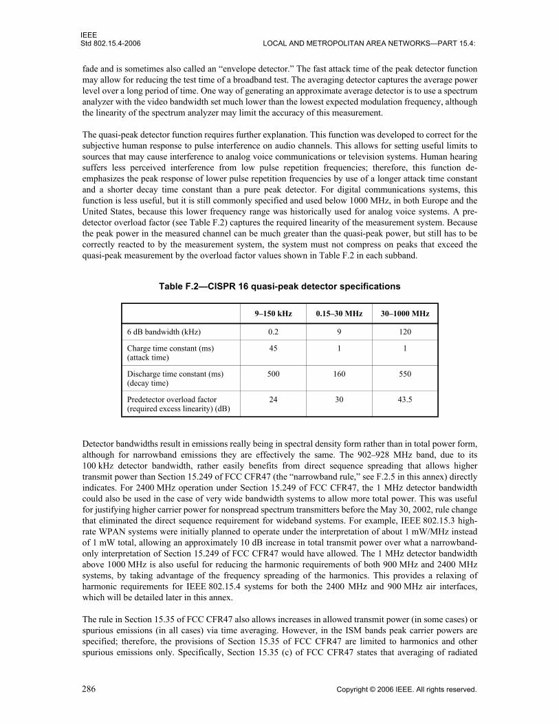
IEEEStd 802.15.4-2006 LOCAL AND METROPOLITAN AREA NETWORKS—PART 15.4:
fade and is sometimes also called an “envelope detector.” The fast attack time of the peak detector functionmay allow for reducing the test time of a broadband test. The averaging detector captures the average powerlevel over a long period of time. One way of generating an approximate average detector is to use a spectrumanalyzer with the video bandwidth set much lower than the lowest expected modulation frequency, althoughthe linearity of the spectrum analyzer may limit the accuracy of this measurement.
The quasi-peak detector function requires further explanation. This function was developed to correct for thesubjective human response to pulse interference on audio channels. This allows for setting useful limits tosources that may cause interference to analog voice communications or television systems. Human hearingsuffers less perceived interference from low pulse repetition frequencies; therefore, this function de-emphasizes the peak response of lower pulse repetition frequencies by use of a longer attack time constantand a shorter decay time constant than a pure peak detector. For digital communications systems, thisfunction is less useful, but it is still commonly specified and used below 1000 MHz, in both Europe and theUnited States, because this lower frequency range was historically used for analog voice systems. A pre-detector overload factor (see Table F.2) captures the required linearity of the measurement system. Becausethe peak power in the measured channel can be much greater than the quasi-peak power, but still has to becorrectly reacted to by the measurement system, the system must not compress on peaks that exceed thequasi-peak measurement by the overload factor values shown in Table F.2 in each subband.
Detector bandwidths result in emissions really being in spectral density form rather than in total power form,although for narrowband emissions they are effectively the same. The 902–928 MHz band, due to its100 kHz detector bandwidth, rather easily benefits from direct sequence spreading that allows highertransmit power than Section 15.249 of FCC CFR47 (the “narrowband rule,” see F.2.5 in this annex) directlyindicates. For 2400 MHz operation under Section 15.249 of FCC CFR47, the 1 MHz detector bandwidthcould also be used in the case of very wide bandwidth systems to allow more total power. This was usefulfor justifying higher carrier power for nonspread spectrum transmitters before the May 30, 2002, rule changethat eliminated the direct sequence requirement for wideband systems. For example, IEEE 802.15.3 high-rate WPAN systems were initially planned to operate under the interpretation of about 1 mW/MHz insteadof 1 mW total, allowing an approximately 10 dB increase in total transmit power over what a narrowband-only interpretation of Section 15.249 of FCC CFR47 would have allowed. The 1 MHz detector bandwidthabove 1000 MHz is also useful for reducing the harmonic requirements of both 900 MHz and 2400 MHzsystems, by taking advantage of the frequency spreading of the harmonics. This provides a relaxing ofharmonic requirements for IEEE 802.15.4 systems for both the 2400 MHz and 900 MHz air interfaces,which will be detailed later in this annex.
The rule in Section 15.35 of FCC CFR47 also allows increases in allowed transmit power (in some cases) orspurious emissions (in all cases) via time averaging. However, in the ISM bands peak carrier powers arespecified; therefore, the provisions of Section 15.35 of FCC CFR47 are limited to harmonics and otherspurious emissions only. Specifically, Section 15.35 (c) of FCC CFR47 states that averaging of radiated
Table F.2—CISPR 16 quasi-peak detector specifications
9–150 kHz 0.15–30 MHz 30–1000 MHz
6 dB bandwidth (kHz) 0.2 9 120
Charge time constant (ms) (attack time)
45 1 1
Discharge time constant (ms) (decay time)
500 160 550
Predetector overload factor (required excess linearity) (dB)
24 30 43.5
286 Copyright © 2006 IEEE. All rights reserved.
IEEEWIRELESS MAC AND PHY SPECIFICATIONS FOR LR-WPANS Std 802.15.4-2006
emission limits may be used and that allowed peak emissions may be as much as 20 dB in excess of statedlimits so long as the maximum averaging time does not exceed 100 ms. The worst-case 100 ms in a longertransmission must be used. Design formulas and examples relative to IEEE Std 802.15.4 will be given laterin this annex. It must be kept in mind that the FCC rules are referring to “emissions” in terms of radiatedroot-mean-square (rms) electric field strength, not directly in terms of power. This averaging rule is oftenhelpful in reducing the difficulty in meeting the low general field strength levels given in Section 15.209 ofFCC CFR47.
Section 6.5 of Canadian RSS-210 also allows for averaging with the same numerical specifications asSection 15.35 of FCC CFR47. Specifically, the averaging shall apply over the worst-case 100 ms period, andpeak power shall not exceed 20 dB more than the allowed average power limit.
F.2.2 Section 15.209 of FCC CFR47
The so-called “general” rule restricts the RF energy that electronic equipment may parasitically emit. Thespecific level of emissions is 200 uV/m at 3 m test range below 960 MHz and 500 uV/m above. These fieldstrengths are approximately equivalent to –49.2 and –41.2 dBm ERP, respectively. The formula used tomake this conversion from rms electric field Erms to transmitted ERP Pterp at range R m is shown inEquation (F.1).
(F.1)
Section 15.209 (d) of FCC CFR47 calls out the same detector functions over frequency as called out inSection 15.35 (b) of FCC CFR47, namely that CISPR quasi-peak detectors are used below 1000 MHz andaveraging detectors above 1000 MHz. Thus these field strength levels are actually field strength spectraldensity rather than total field strength. The densities are per 100 kHz below 1000 MHz and per 1 MHz =above 1000 MHz.
This rule governs the general spurious nonharmonic emissions that IEEE 802.15.4 equipment can emit inthe United States, and where harmonics fall into restricted bands, it also limits harmonics. The 2nd and 3rdharmonics of the 2400 MHz ISM band do fall into restricted bands as given in Section 15.205 of FCCCFR47, as do the 3rd and 5th harmonics of the 900 MHz ISM band. Again, the Canadian regulationsoutlined in Section 6.2.1 of Canadian RSS-210 are nearly identical.
F.2.3 Section 15.205 of FCC CFR47
This subclause documents the restricted bands (see Table F.3) where only spurious emissions are allowedand where those emissions must meet the general levels of Section 15.209 of FCC CFR47. Above1000 MHz, averaging according to Section 15.35 of FCC CFR47 may be used.
Note that the 2nd and 3rd harmonics of equipment in the 2400 MHz ISM band fall into restricted bands, asdo the 3rd and 5th harmonics of 902–928 MHz. The restricted band from 2483.5 MHz to 2500 MHz is alsoa cause for potential concern for close-in spurious emissions from IEEE 802.15.4 transmissions, with thehighest center channel setting at 2480 MHz being only 3.5 MHz away.
The restricted bands used in Canada are almost identical to the ones shown in the Table F.3. See Table 2 ofCanadian RSS-210 to note the differences.
The limit of 500 uV/m at 3 m is approximately –41 dBm/MHz ERP; therefore, for approximately –1 dBmnarrowband continuous transmission, at least 40 dB harmonic suppression is required. For the 2400 MHzdirect sequence IEEE 802.15.4 system with approximately 1 MHz 3 dB power bandwidth, there is amoderate relaxation of this requirement due to spreading. At the 2nd harmonic, the power bandwidth is
Pterp 0.03333R2Erms2=
Copyright © 2006 IEEE. All rights reserved. 287

IEEEStd 802.15.4-2006 LOCAL AND METROPOLITAN AREA NETWORKS—PART 15.4:
approximately 2 MHz; therefore, for a 1 MHz detector bandwidth, the requirement is relaxed 3 dB to yield a–38 dBc harmonic suppression requirement. For a 3 MHz power bandwidth at the 3rd harmonic of2400 MHz, the relaxation is 4.8 dB (see F.5). For the 900 MHz U.S. (40 kb/s, 600 kchip/s) IEEE 802.15.4air interface, the 3rd and 5th harmonics fall into these restricted bands. The fundamental 3 dB bandwidth ofthe 900 MHz PHY is about equal to the chip rate and, therefore, is about 600 kHz. At the 3rd harmonic, thisallows a relaxation of about 2.5 dB and, at the 5th harmonic, a relaxation of about 4.8 dB. Even with theserelaxations, these harmonic requirements are fairly difficult for low-cost equipment; but the use of theaveraging rules of Section 15.35 of FCC CFR47 applied to the actual transmit times of IEEE 802.15.4packets will relax them considerably more. Harmonic requirements are quantified in F.5 and F.6.
F.2.4 Section 15.247 of FCC CFR47
Section 15.247 of FCC CFR47 is the primary category for U.S. operations of IEEE 802.15.4 equipment.This service category provides the potential for the highest performance of all the unlicensed servicecategories, allowing freedom from licensing, transmit powers up to 1 W, and no limitations for applicationor transmit duty cycle. This rule is applicable to the ISM bands, which are 902 MHz to 928 MHz, 2400 MHzto 2483.5 MHz, and 5725 MHz to 5850 MHz. Of these bands, only the 2400–2483.5 MHz band provides anearly worldwide available band of suitable power and freedom from applications restrictions for IEEEStd 802.15.4.
Table F.3—Partial list of restricted frequencies under Section 15.205 of FCC CFR47
Restricted frequency range
240–285 MHz
322–335.4 MHz
399.9–410 MHz
608–614 MHz
960–1240 MHz
1300–1427 MHz
1435–1626.5 MHz
1645.5–1646.5 MHz
1660–1710 MHz
1718.8–1722.2 MHz
2200–2300 MHz
2310–2390 MHz
2483.5–2500 MHz
2655–2900 MHz
3260–3267 MHz
4.5–5.15 GHz
7.25–7.75 GHz
10.6–12.7 GHz
288 Copyright © 2006 IEEE. All rights reserved.

IEEEWIRELESS MAC AND PHY SPECIFICATIONS FOR LR-WPANS Std 802.15.4-2006
Until May 30, 2002, this service category required either FHSS or DSSS, or a combination. However, at thattime, the requirement for direct sequence was replaced by digital modulation, which was defined asmodulation that satisfied the following two requirements:
a) 6 dB bandwidth of 500 kHz or more
b) Spectral density not to exceed +8 dBm/3 kHz
Note that the 2 Mchip/s O-QPSK waveform of the IEEE 802.15.4 2400 MHz air interface, with 6 dBbandwidth of about 1.5 MHz, and the 600 kc/s BPSK waveform of the 902–928 MHz air interface, withbandwidth of about 600 kHz, both meet the definition of digital modulation.
Allowed transmit power is up to 1 W delivered at the antenna port, with a maximum antenna gain up to6 dBi. If antenna gain is greater than 6 dBi, then transmit power must be reduced by an amount equal to thedecibel measure of how much the antenna gain exceeds 6 dBi. However, for 2400 MHz fixed point-to-pointoperations, the transmit power need only be reduced by 1 dB for every 3 dB that antenna gain exceeds 6 dBi.
The spurious and harmonic requirement of Section 15.247 of FCC CFR47 is a rather easily achieved–20 dBc, as measured in a detector bandwidth 100 kHz wide and compared to the 100 kHz of the modulatedcarrier that contains the highest power. However, it must be noted that the 2nd and 3rd harmonics of2400 MHz and the 3rd and 5th harmonics of 900 MHz fall into restricted bands as given in Section 15.205 ofFCC CFR47 and thus have stricter requirements. As discussed above, these requirements can then bemitigated by the 1 MHz detector bandwidth and averaging effects of Section 15.35 of FCC CRF47. Theresulting requirements will be quantified in F.5 and F.6.
F.2.5 Section 15.249 of FCC CFR47
The service category of Section 15.249 of FCC CFR47 provides for narrowband (nonspread spectrum)operation in the same ISM band of 902 MHz to 928 MHz, 2300 MHz to 2383.5 MHz, and 5725 MHz to5850 MHz. Operation is allowed up to 50 mV rms of electric field strength from a transmitter at a 3 m testrange. This is equivalent to 0.75 mW ERP [see Equation (F.1)]. Under Section 15.35 of FCC CRF47, thesefield strengths are actually interpreted as field strength spectral densities and are per 100 kHz for the 902–928 MHz band and per 1 MHz for the two higher bands. The harmonic requirement is a difficult –40 dBcrelative to the maximum allowed power, and the restricted bands can require additional suppression.Fortunately the provisions of Section 15.35 of FCC CRF47 can be applied to reduce these difficultrequirements.
IEEE 802.15.4 equipment would not generally be certified under this category, but it could be if the productmanufacturer chose to do so. For 902–928 MHz operation, it is not as disadvantageous as it might seembecause the interpretation of Section 15.35 of FCC CRF47 as a transmitted density allows higher 900 MHzpowers for IEEE 802.15.4 equipment than for narrowband equipment. Because the detector bandwidth usedfor certification testing in this band is 100 kHz wide, the 902–928 MHz air interface with about 600 kHzbandwidth could be certified under this service category at up to about +6.5 dBm. However, because thedetector bandwidth at 2400 MHz is 1 MHz and the 3 dB bandwidth of the 2400 GHz air interface is alsoabout 1 MHz, the carrier power is still limited to the narrowband limit of about –1 dBm. Concerningharmonics, because the 2nd and 3rd harmonics of 2400 MHz and the 3rd and 5th harmonics of 900 MHz fallinto restricted bands anyway, only the 2nd harmonic of 900 MHz really benefits from the relaxed –20 dBcharmonic requirement given in Section 15.247 of FCC CFR47. With that exception, the harmonicrequirements of Section 15.247 and Section 15.249 of FCC CFR47 are practically the same because theyhappen to have restricted band limits for low-order harmonics.
See Section 6.2.2 (m) of Canadian RSS-210 for the 902–928 MHz and 2400–2483.5 MHz narrowbandauthorizations that are identical to Section 15.249 of FCC CFR47.
Copyright © 2006 IEEE. All rights reserved. 289

IEEEStd 802.15.4-2006 LOCAL AND METROPOLITAN AREA NETWORKS—PART 15.4:
F.3 Applicable European rules
The over 40 member nations of the European Conference of Postal and TelecommunicationsAdministrations (CEPT) have established a fairly high degree of standardization throughout Europe on theoperation of low-power radio equipment. Most disagreements are in the nature of allowed modes andtransmit duty cycles that may be accounted for in software control, allowing the same hardware andtechnical standards to be used throughout Europe. The ETSI develops technical standards for CEPTcountries. Requirements are spread across multiple documents, as shown in Table F.4 and are influenced byother documents as well. It is not always clear when European community advisory and recommendationdocuments have attained the force of law; therefore, the regulatory requirements of a particular nation mustbe checked before planning to market equipment there.
The most fundamental document to use as a starting point in understanding general low-power radiooperation in Europe is ERC Recommendation 70-03 [B24] on SRD, downloadable from www.ero.dk. Thisdocument gives a general description of recommended applications, frequencies, powers, and otherspecifications. It provides advisory recommendations for narrowband operation in the 2400 MHz ISM bandin the table of Annex 1 and allows up to 10 mW EIRP in narrowband or spread spectrum mode. ERC 70-03is particularly applicable to IEEE 802.15.4 equipment operating in the European 868.0–868.6 MHz bandsegment. However, for ISM band spread spectrum operation, such as IEEE 802.15.4 equipment operating at2400 MHz with bit rates greater than or equal to 250 kb/s, ETSI EN 300 328 ([B26] and [B27]) is in generalthe formal governing document (although it may be overruled by the regulatory documents of a specificnation). For devices with less than 10 mW EIRP, the rules of Section 5 of ETSI EN 300 328 may be used orthe rules of Annex 1 of ERC 70-03. For power levels between 10 mW and 100 mW in the 2400 MHz band,only ETSI EN 300 328 applies, and DSSS or FHSS must be used.
Details on test methodology to confirm compliance are given in CISPR 16-1: 1999 and in ETSIEN 300 220-1 [B25]. An important general note is the bandwidths in which carrier and spurious emissionsare measured. The specification of bandwidth actually means that what is commonly referred to as power is
Table F.4—Primary European rules documents
Specification Number Title Comment
IEC CISPR 16-1 series of standards [B31]
Specifications for radio disturbance and immunity measuring apparatus and methods: Part 1: Radio disturbance and immunity measuring apparatus
Specifications on test methods and equipment, including EMC antennas and the CISPR 16 quasi-peak detector that are referenced, but not provided in other sources. Available from the IEC.
ERC Recommendation 70-03 [B24]
Relating to the Use of Short Range Devices (SRDs)
General recommendations that are loosely followed by most European nations.
ETSI EN 300 328-1 [B26] Electromagnetic Compatibility and Radio Spectrum Matters (ERM); Wideband Transmission Systems; Part 1
European rules for spread spectrum systems in ISM bands. Available from ETSI.
ETSI EN 300 328-2 [B27] Electromagnetic Compatibility and Radio Spectrum Matters (ERM); Wideband Transmission Systems; Part 2
European rules for spread spectrum systems in ISM bands. Available from ETSI.
ETSI EN 300 220-1 [B25] Electromagnetic Compatibility and Radio Spectrum Matters (ERM); Short Range Devices (SRDs); Part 1
Provides details on European test methodology to confirm compliance.
290 Copyright © 2006 IEEE. All rights reserved.

IEEEWIRELESS MAC AND PHY SPECIFICATIONS FOR LR-WPANS Std 802.15.4-2006
really PSD, and total power over wider bandwidth than the detector may be higher than the level allowedwithin a detector bandwidth. Fortunately, the standards chosen are basically the standards also specified inthe FCC rules. Table 5 in Section 6.6 of ETSI EN 300 220-1 specifies that below 1000 MHz a test spectrumanalyzer bandwidth of 100 kHz shall normally be used, and above 1000 MHz a bandwidth of 1 MHz shall beused. This is in general identical to the provisions of FCC 15.35. However, a slight variance exists in thatTable 5 also states that below 25 MHz a bandwidth of 10 kHz shall be used, and below 150 kHz a bandwidthof 1 kHz shall be used. The zone between 150 kHz and 25 MHz is one in which clock and digital noise doeshave a potential to cause difficulty; therefore, certification laboratories will normally conduct testing overthat band. Note that the ETSI EN 300 220-1 frequency boundary for changing detector bandwidths is25 MHz as opposed to the 30 MHz given in CISPR 16-1: 1999.
An important difference in the European rules as compared to the FCC rules are provisions that go beyondpreventing interference to other systems, which is a primary goal of the FCC rules, into attempting toguarantee acceptable system performance. This is captured in law in that most electronic equipment sold inthe European Union must comply with EMC Directive 89/336/EEC10 and carry the CE Marking that claimscompliance. After April 8, 2000, compliance with these requirements could be self-certified by certainprocedures (see www.ero.dk). Another document governing required performance its ETSI EN 300 683[B28]. This document’s performance requirements are centered on interference immunity from both outsideelectromagnetic fields and disturbances on power supply and control inputs. These documents referenceother documents as well, the full set of which must be reviewed by manufacturers.
F.3.1 European 2400 MHz band rules
Basic 2400 MHz band parameters extracted from ETSI EN 300 328 are given in Table F.5.
10Information on EMC Directive 89/336/EEC is available at http://ec.europa.eu/enterprise/electr_equipment/emc/index.htm.
Table F.5—Basic general 2400 MHz band parameters from ETS EN 300 328
Parameter Specifications Comments
Carrier frequency 2400 MHz to 2483.5 MHz
Transmit power 100 mW ERP maximum
Modulation Frequency hopping: At least 20 channels with 0.4 s maximum dwell timeDirect sequence: ERP limited to 10 mW/MHz maximum
In addition to spread spectrum, data rates greater than or equal to 250 kb/s are required.
Narrowband spurious emissions from 30 MHz to 1 GHz
–36 dBm ERP operating–57 dBm ERP standby
Narrowband spurious emissions from 1 GHz to 12.75 GHz
–30 dBm operating–47 dBm standby
Approximately 10 dB more relaxed on 2nd and 3rd harmonic than U.S. requirement.
Narrowband spurious emissions 1.8 GHz to 1.9 GHz and 5.15 GHz to 5.3 GHz
–47 dBm operating–47 dBm standby
Wideband spurious emissions from 30 MHz to 1 GHz
–87 dBm/Hz ERP operating–107 dBm ERP standby
Copyright © 2006 IEEE. All rights reserved. 291

IEEEStd 802.15.4-2006 LOCAL AND METROPOLITAN AREA NETWORKS—PART 15.4:
Note that the wideband spurious emission may be interpreted so that transmitted phase noise, as spread bythe DSSS modulation, must meet –80 dBm/Hz general wideband level at the band edge.
The allowed emission by the receiver portion of the device, which is presumably interpreted as during thereceive time of a transceiver, are given in Section 5.3.2 of ETSI EN 300 328-1 [B26] and documented inTable F.6.
There are country-by-country exceptions to the 2400 MHz rules that change over time. The latest exceptionsmay be noted by referring to the current revision of Annex 1 of ERC Recommendation 70-03 [B24]. Otherapplications that could cause potential interference to IEEE 802.15.4 2400 MHz band operation are notedbelow.
Railway autoidentification systems in Europe are allocated at 2446 MHz to 2454 MHz and, because they arefairly powerful, could cause interference to IEEE 802.15.4 systems using these frequencies. There are fivenarrowband channels of 1.5 MHz each over this band, at transmit powers up to 500 mW in the presence ofthe train. See Annex 4 of ERC 70-03 for more details.
Equipment for detecting movement is authorized in 2400 MHz to 2483.5 MHz at power levels up to 25 mW.See Annex 6 of ERC 70-03.
F.3.2 European 868–870 MHz band rules
This information is provided in support of the version of the 900 MHz air interface that has been developedfor the European 868–870 MHz band. This air interface provides 20 kb/s raw data rate using 300 kc/s and
Wideband spurious emissions from 1 GHz to 12.75 GHz
–80 dBm/Hz operating–97 dBm/Hz standby
Note that the interpretation of the transmitted modulation sidebands and phase noise out of band must meet these levels.
Narrowband spurious emissions 1.8 GHz to 1.9 GHz and 5.15 GHz to 5.3 GHz
–97 dBm/Hz operating–97 dBm/Hz standby
Table F.6—Allowed receiver spurious emissions for 2400 MHz band from ETSI EN 300 328
Parameter Specification
Narrowband RX emissions 30 MHz to 1 GHz –57 dBm
Narrowband RX emissions 1 GHz to 12.75 GHz –47 dBm
Wideband RX emissions 30 MHz to 1 GHz –107 dBm/Hz
Narrowband RX emissions 1 GHz to 12.75 GHz –97 dBm/Hz
Table F.5—Basic general 2400 MHz band parameters from ETS EN 300 328 (continued)
Parameter Specifications Comments
292 Copyright © 2006 IEEE. All rights reserved.
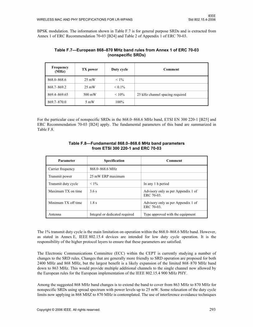
IEEEWIRELESS MAC AND PHY SPECIFICATIONS FOR LR-WPANS Std 802.15.4-2006
BPSK modulation. The information shown in Table F.7 is for general purpose SRDs and is extracted fromAnnex 1 of ERC Recommendation 70-03 [B24] and Table 2 of Appendix 1 of ERC 70-03.
For the particular case of nonspecific SRDs in the 868.0–868.6 MHz band, ETSI EN 300 220-1 [B25] andERC Recommendation 70-03 [B24] apply. The fundamental parameters of this band are summarized inTable F.8.
The 1% transmit duty cycle is the main limitation on operation within the 868.0–868.6 MHz band. However,as stated in Annex E, IEEE 802.15.4 devices are intended for low duty cycle operation. It is theresponsibility of the higher protocol layers to ensure that these parameters are satisfied.
The Electronic Communications Committee (ECC) within the CEPT is currently studying a number ofchanges to the SRD rules. Changes that are generally more friendly to SRD operation are proposed for both2400 MHz and 868 MHz, but the largest benefit is a likely expansion of the limited 868–870 MHz banddown to 863 MHz. This would provide multiple additional channels to the single channel now allowed bythe European rules for the European implementation of the IEEE 802.15.4 900 MHz PHY.
Among the suggested 868 MHz band changes is to extend the band to cover from 863 MHz to 870 MHz fornonspecific SRDs using spread spectrum with power levels up to 25 mW. Some relaxation of the duty cyclelimits now applying in 868 MHZ to 870 MHz is contemplated. The use of interference avoidance techniques
Table F.7—European 868–870 MHz band rules from Annex 1 of ERC 70-03(nonspecific SRDs)
Frequency (MHz) TX power Duty cycle Comment
868.0–868.6 25 mW < 1%
868.7–869.2 25 mW < 0.1%
869.4–869.65 500 mW < 10% 25 kHz channel spacing required
869.7–870.0 5 mW 100%
Table F.8—Fundamental 868.0–868.6 MHz band parameters from ETSI 300 220-1 and ERC 70-03
Parameter Specification Comment
Carrier frequency 868.0–868.6 MHz
Transmit power 25 mW ERP maximum
Transmit duty cycle < 1% In any 1 h period
Maximum TX on time 3.6 s Advisory only as per Appendix 1 of ERC 70-03.
Minimum TX off time 1.8 s Advisory only as per Appendix 1 of ERC 70-03.
Antenna Integral or dedicated required Type approved with the equipment
Copyright © 2006 IEEE. All rights reserved. 293
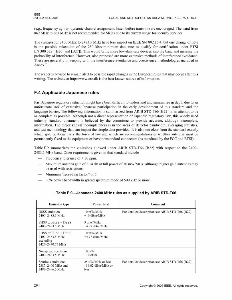
IEEEStd 802.15.4-2006 LOCAL AND METROPOLITAN AREA NETWORKS—PART 15.4:
(e.g., frequency agility, dynamic channel assignment, listen before transmit) are encouraged. The band from862 MHz to 863 MHz is not recommended for SRDs due to its current usage for security services.
The changes for 2400 MHZ to 2483.5 MHz have less impact on IEEE Std 802.15.4, but one change of noteis the possible relaxation of the 250 kb/s minimum data rate to qualify for certification under ETSIEN 300 328 ([B26] and [B27]). This would bring more low-data-rate devices into the band and increase theprobability of interference. However, also proposed are more extensive methods of interference avoidance.These are generally in keeping with the interference avoidance and coexistence methodologies included inAnnex E.
The reader is advised to remain alert to possible rapid changes in the European rules that may occur after thiswriting. The website at http://www.ero.dk is the best known source of information.
F.4 Applicable Japanese rules
Past Japanese regulatory situation might have been difficult to understand and summarize in depth due to anunfortunate lack of extensive Japanese participation in the early development of this standard and thelanguage barrier. The following information is summarized from ARIB STD-T66 [B22] in an attempt to beas complete as possible. Although not a direct representation of Japanese regulatory law, this widely usedindustry standard document is believed by the committee to provide accurate, although incomplete,information. The major known incompleteness is in the areas of detector bandwidth, averaging statistics,and test methodology that can impact the simple data provided. It is also not clear from the standard exactlywhich specifications carry the force of law and which are recommendations or whether antennas must bepermanently fixed to the equipment or have nonstandard connectors (as mandated by the FCC and ETSI).
Table F.9 summarizes the emissions allowed under ARIB STD-T66 [B22] with respect to the 2400–2483.5 MHz band. Other requirements given in that standard include
— Frequency tolerance of ± 50 ppm.— Maximum antenna gain of 2.14 dB at full power of 10 mW/MHz, although higher gain antennas may
be used with restrictions.— Minimum “spreading factor” of 5.— 90% power bandwidth in spread spectrum mode of 500 kHz or more.
Table F.9—Japanese 2400 MHz rules as supplied by ARIB STD-T66
Emission type Power level Comment
DSSS emission2400–2483.5 MHz
10 mW/MHz+10 dBm/MHz
For detailed description see ARIB STD-T66 [B22].
FHSS or FHSS + DSSS2400–2483.5 MHz
3 mW/MHz+4.77 dBm/MHz
FHSS or FHSS + DSSS2400–2483.5 MHzexcluding2427–2470.75 MHz
10 mW/MHz+4.77 dBm/MHz
Nonspread spectrum2400–2483.5 MHz
10 mW+10 dBm
Spurious emissions2387–2400 MHz and2483–2496.5 MHz
25 uW/MHz or less–16.02 dBm/MHz or less
For detailed description see ARIB STD-T66 [B22].
294 Copyright © 2006 IEEE. All rights reserved.

IEEEWIRELESS MAC AND PHY SPECIFICATIONS FOR LR-WPANS Std 802.15.4-2006
F.5 Emissions specification analysis with respect to known worldwide regulations
Based on the above rules, a set of spurious emission requirements that allows meeting the regulations of themajority of the world’s nations may be developed. Where provided, detector specifications and averagingeffects may sometimes need to be used to relax requirements. Meeting requirements may have a noticeableeffect on build-of-materials cost and design choices; therefore, best efforts have been made to inferminimum requirements that support the lowest possible manufacturing cost.
F.5.1 General analysis and impact of detector bandwidth and averaging rules
The use of averaging and detector bandwidths that allow some relaxation of specifications is described wellin the FCC rules and similarly in the Canadian rules. European rules do not allow for averaging, but doprovide for detector bandwidths that provide some relaxation also. Japanese detector specification andaveraging rules suggest corresponding levels of Japanese regulations are no more restrictive than the U.S. orEuropean regulations. The U.S. rules as related to the restricted bands as described in Section 15.205 of FCCCFR47 appear to be the most restrictive, although analysis using the detector and averaging provisions ofSection 15.35 of FCC CFR47 with the parameters of the transmitted data leads to the conclusion thatEuropean limits are usually the worst case.
The critical facts relative to the U.S. rules are as follows:
— The allowed ERP of spurious emissions (including harmonics falling in restricted bands) isapproximately –41 dBm.
— The detector bandwidth used for certification testing is 1 MHz, and the 3 dB modulation bandwidthat the 2400 MHz fundamental planned under the standard is slightly less than 1 MHz.
— The averaging provisions of Section 15.35 of FCC CRF47 apply, which allow averaging over a100 ms period with maximum increase in peak power limited to 20 dB. The units of measure areelectric field strength; and although rms is not explicitly stated, rms units are standard for FCCmeasurements.
The mathematics of FCC duty cycle averaging are not given in the regulations, but may be quickly derived,keeping in mind that units are rms electric field strength (not power). The following definitions are made:
Dc = highest carrier duty cycle over a 100 ms period.
Ess = field strength steady state = allowed rms field strength at a particular frequency without averaging.
Spurious emissionsf < 2387 MHz and f > 2496.5 MHz
2.5 uW/MHz or less–26.02 dBm/MHz or less
For detailed description see ARIB STD-T66 [B22].
RX emissionsf < 1000 MHz
4 nW–53.98 dBm
Applicable to receive mode spurs such as local oscillator leakage.
RX emissionsf > 1000 MHz
20 nW–46.99 dBm
Table F.9—Japanese 2400 MHz rules as supplied by ARIB STD-T66 (continued)
Emission type Power level Comment
Copyright © 2006 IEEE. All rights reserved. 295

IEEEStd 802.15.4-2006 LOCAL AND METROPOLITAN AREA NETWORKS—PART 15.4:
Epa = field strength peak allowed when averaging = allowed peak field strength at a particular duty cycleand frequency when averaging. Note that according to FCC convention, this “peak” is not the true RF peak.It is the rms carrier strength in volts per meter at the peak of the envelope.
Pss = steady-state power allowed when not averaging.
Ppa = peak power allowed when averaging.
The duty cycle is reduced by an average of –3 dB for ASK modulation, but for the 2400 MHz air interface, anearly constant envelope form of modulation (O-QPSK) is used. Thus duty cycle is simply time on aparticular channel relative to 100 ms as shown in Equation (F.2).
(F.2)
The maximum spurious field peak field strength allowed under the rules will then be as shown inEquation (F.3).
(F.3)
This value is the maximum allowed peak of the envelope of a carrier measured in rms electric field strength,up to a limit of 10 times the steady-state allowed rms field (Ess).
Equation (F.3) can be solved for the allowed duty cycle given peak field strength that a system is capable ofand put it into power terms as shown in Equation (F.4).
(F.4)
For peak power allowed when averaging using narrowband emitters (bandwidth less than regulatorydetector bandwidth), compute
(narrowband emitters) (F.5)
where the minimum value of is 0.01 (maximum boost of 20 dB when duty cycle = 10% or less).
If the protocol is less than 100% duty cycle over 100 ms, then the averaging effect illustrated inEquation (F.5) may be used to reduce restricted band harmonic attenuation requirements, where Ppa isunderstood to mean peak harmonic power allowed during carrier on times and Pss is the steady-state allowedpower level in the detector bandwidth. The 500 uV/m allowed steady-state level in restricted bandscorresponds to 7.5 × 10^8 W ERP, or –41.2 dBm ERP, which may be a significant level of attenuation toattain in low-cost equipment. A 50% duty cycle over 100 ms could, for example, reduce this difficultrequirement by 6 dB.
Beyond averaging, additional help on the required harmonic attenuation levels for restricted band harmonicsresults from taking the transmitted bandwidth BWh at the harmonic frequency and regulatory compliance
DcToc
0.1-------=
EpaEss
Dc-------=
DcEss
Epa--------
Pss
Ppa-------- AllowedPowerSteadyState
PeakPowerAllowed-----------------------------------------------------------------------= = =
PpaPss
Dc2--------=
Dc2
296 Copyright © 2006 IEEE. All rights reserved.

IEEEWIRELESS MAC AND PHY SPECIFICATIONS FOR LR-WPANS Std 802.15.4-2006
detector bandwidth BWd (1 MHz above 1000 MHz, and 100 kHz below 1000 MHz) into account. This caseof wider band emissions in Equation (F.5) may be extended to
(wideband and narrowband emitters) (F.6)
Here HPpa is harmonic power peak allowed and refers to the total harmonic power and not necessarily theharmonic power captured within the detector bandwidth. M is a factor given by
(F.7)
where h is the harmonic numberBWf is the effective power bandwidth (approximately the 3 dB bandwidth) at the fundamental
The total harmonic peak power allowed of Equation (F.6) may be expressed in decibels relative to 1 mWwhere duty cycle Dc is between 0.1 and 1.0 as given in Equation (F.8).
(F.8)
When duty cycle is less than 10%, the total peak harmonic power allowed in decibels relative to 1 mW ERPis given by Equation (F.9).
(F.9)
These results may be used to calculate the total harmonic ERP for IEEE 802.15.4 packets as given in F.5.2.
F.5.2 Frequency spreading and averaging effects specific to IEEE Std 802.15.4
This subclause is primarily applicable to FCC rules in the United States, but there is also a modest relaxationof European harmonic requirements that may be inferred from detector bandwidth and direct sequencespreading. The United States has more relaxed harmonic requirements except when harmonics fallin restricted bands, in which case, the requirements are then more difficult than Europe, but are thenmitigated by the averaging allowances of Section 15.35 of FCC CFR47. Analysis to be shortly reviewed willshow that the resulting U.S. requirement is about –20 dBm and is thus approximately 10 dB more relaxedthan the –30 dBm European requirement.
Under Section 15.247 of FCC CFR47, harmonics that do not fall in restricted bands have a requirement of–20 dBc as measured in a 100 kHz detector bandwidth when compared to the 100 kHz segment within thefundamental transmission that has the highest power. Because a smaller frequency at the fundamentalspreads out to provide the 100 kHz at the harmonic, the requirement is actually even more relaxed that the–20 dBc would indicate. For example, at the 2nd harmonic, if the transmitter harmonic level and filteringeffectiveness for a narrowband transmission provided –17 dBc, then once well spread with DSSS, only50 kHz at the fundamental will spread out to 100 kHz at the 2nd harmonic. The –17 dBc that thetransmitter gives narrowband would be increased to –20 dBc when spread. A formula giving the narrowbandtransmitter harmonic performance that will meet the –20 dBc requirement when spread, where h is theharmonic number, is given in Equation (F.10).
HPpa MPss
Dc2--------=
M1
BWh
BWd-----------
hBWf
BWd-------------=
⎩⎪⎨⎪⎧
=
if BWh <= BWd
if BWh > BWd
HPpa dBm( ) 10 Mlog 10 Dc2log– 41.2–=
HPpa dBm( ) 10 Mlog 21.2–=
Copyright © 2006 IEEE. All rights reserved. 297
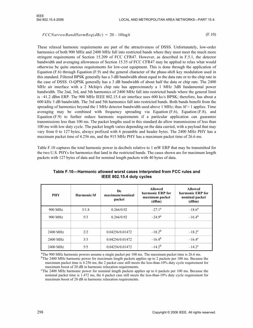
IEEEStd 802.15.4-2006 LOCAL AND METROPOLITAN AREA NETWORKS—PART 15.4:
(F.10)
These relaxed harmonic requirements are part of the attractiveness of DSSS. Unfortunately, low-orderharmonics of both 900 MHz and 2400 MHz fall into restricted bands where they must meet the much morestringent requirements of Section 15.209 of FCC CFR47. However, as described in F.5.1, the detectorbandwidth and averaging allowances of Section 15.35 of FCC CFR47 may be applied to relax what wouldotherwise be quite onerous requirements for low-cost equipment. This is done through the application ofEquation (F.6) through Equation (F.9) and the general character of the phase-shift key modulation used inthis standard. Filtered BPSK generally has a 3 dB bandwidth about equal to the data rate or to the chip rate inthe case of DSSS. O-QPSK generally has a 3 dB bandwidth of about half the data or chip rate. The 2400MHz air interface with a 2 Mchip/s chip rate has approximately a 1 MHz 3dB fundamental powerbandwidth. The 2nd, 3rd, and 5th harmonics of 2400 MHz fall into restricted bands where the general limitis –41.2 dBm ERP. The 900 MHz IEEE 802.15.4 air interface uses 600 kc/s BPSK; therefore, has about a600 kHz 3 dB bandwidth. The 3rd and 5th harmonics fall into restricted bands. Both bands benefit from thespreading of harmonics beyond the 1 MHz detector bandwidth used above 1 MHz; thus M > 1 applies. Timeaveraging may be combined with frequency spreading via Equation (F.6), Equation (F.8), andEquation (F.9) to further reduce harmonic requirements if a particular application can guaranteetransmissions less than 100 ms. The packet lengths used in this standard do allow transmissions of less than100 ms with low duty cycle. The packet length varies depending on the data carried, with a payload that mayvary from 0 to 127 bytes, always prefixed with 6 preamble and header bytes. The 2400 MHz PHY has amaximum packet time of 4.256 ms, and the 915 MHz PHY has a maximum packet time of 26.6 ms.
Table F.10 captures the total harmonic power in decibels relative to 1 mW ERP that may be transmitted forthe two U.S. PHYs for harmonics that land in the restricted bands. The cases shown are for maximum lengthpackets with 127 bytes of data and for nominal length packets with 40 bytes of data.
Table F.10—Harmonic allowed worst cases interpreted from FCC rules and IEEE 802.15.4 duty cycles
PHY Harmonic/MDc
maximum/nominal packet
Allowedharmonic ERP for maximum packet
(dBm)
Allowedharmonic ERP for
nominal packet(dBm)
900 MHz 3/1.8 0.266/0.92 –27.1a
aThe 900 MHz harmonic powers assume a single packet per 100 ms. The maximum packet time is 26.6 ms.
–18.6a
900 MHz 5/3 0.266/0.92 –24.9a –16.4a
2400 MHz 2/2 0.04256/0.01472 –18.2b
bThe 2400 MHz harmonic power for maximum length packets applies up to 2 packets per 100 ms. Because themaximum packet time is 4.256 ms, the 2 packet case still meets the less-than-10% duty cycle requirement formaximum boost of 20 dB in harmonic relaxation requirements.
–18.2c
cThe 2400 MHz harmonic power for nominal length packets applies up to 6 packets per 100 ms. Because thenominal packet time is 1.472 ms, the 6 packet case still meets the less-than-10% duty cycle requirement formaximum boost of 20 dB in harmonic relaxation requirements.
2400 MHz 3/3 0.04256/0.01472 –16.4b –16.4c
2400 MHz 5/5 0.04256/0.01472 –14.2b –14.2c
FCCNarrowBandHarmReq dBc( ) 20 10 hlog–=
298 Copyright © 2006 IEEE. All rights reserved.

IEEEWIRELESS MAC AND PHY SPECIFICATIONS FOR LR-WPANS Std 802.15.4-2006
When these relaxations are taken into account, it must also be considered that whip antennas will generallyre-resonate on odd harmonics and show a higher directivity than they do at the fundamental. Severaldecibels of safety margin must be left to deal with this factor. It must also be understood that, in giving theresults of Table F.10 in total harmonic power, less harmonic power will be measured when using thestandard measurement bandwidth of 1 MHz, due to the fact that the harmonics of the DSSS transmission aregreater than 1 MHz. The factor 10logM for each harmonic gives the approximate decibel measure of howmuch less the harmonic measured at the center of the transmitted harmonic is than the total harmonic power.
Note that the European requirement for harmonics of 2400 MHz is –30 dBm in a 1 MHz detector bandwidth,with no provision for time averaging. The actual harmonic requirement of the transmitter system is similarto Equation (F.10) and may be written as shown in Equation (F.11).
(F.11)
To use this equation, one turns on a steady-state carrier without modulation or chipping and measuresharmonic performance either via cable or via open air link (taking antenna aperture into account). If themeasured performance is better than the requirement given in Equation (F.11), then the system should pass.
In general the European requirement for 2400 GHz is about 10 dB better than the FCC requirements, takingrestricted bands and averaging into account; therefore, a product that passes European harmonicrequirements should have a comfortable margin for the U.S. market.
F.6 Summary of out-of-band spurious emissions limits
Table F.11 summarizes the allowed spurious emissions for both U.S. and European limits. The levels below30 MHz are provided because radiation from clocks and other digital noise sources can sometimes exceedallowed levels. Known Japanese limits were given in Table F.9.
All FCC emissions are steady-state limits and, when above 1000 MHz, could be relaxed via Section 15.35time averaging and detector bandwidth frequency spreading. For European operation, similar detectorbandwidths apply, but not the time averaging effects. The –30 dBm European harmonic requirement,relaxed as given in Equation (F.11), provides a worst-case level of required harmonic performance that is ingeneral about 10 dB more stringent that the U.S. requirements when analyzed in light of Section 15.35 ofFCC CFR47.
Table F.11—Out-of-band spurious emissions power limits for the United States and Europe
Frequency band or harmonics FCC ETSI
active modeETSI
standby mode
9–490 kHz 2400/kHz uVrms/m/100 kHz@ 300 m
490 kHz–1.705 MHz 2400/kHz uVrms/m/100 kHz@ 30 m
1.705–30 MHz 30 uVrms/m/100 kHz @30 m–45.7 dBm EIRP
30–88 MHz 100 uVrms/m/100 kHz @ 3 m–55.2 dBm EIRP
–36 dBm EIRP/100 kHz –57 dBm EIRP/100 kHz
EuropeanNarrowBandHarmReq dBm( ) 30– 10 hlog+=
Copyright © 2006 IEEE. All rights reserved. 299

IEEEStd 802.15.4-2006 LOCAL AND METROPOLITAN AREA NETWORKS—PART 15.4:
F.7 Phase noise requirements inferred from regulatory limits
Regulatory spurious emissions limits with known detector bandwidths may be inferred to set a phase noiselimit on the transmitter carrier generating synthesizer system.
For European 2400 MHz operation, the wide spurious limit under Section 5.2.4 of ETSI EN 300 328 is–80 dBm/Hz from 1 GHz to 12.5 GHz. Because the nearest channel to the band edge in the 2400–2483.5 MHz band is 2480 MHz, this rule sets a worst-case phase noise at 3.5 MHz offset of –80 dBm/Hz.This is converted to phase noise relative to the carrier by taking into account the direct sequence spreadingand the maximum carrier power. The phase noise is relaxed by the spreading gain (about 9 dB for the2400 MHz air interface), allowing a maximum unspread phase noise of –71 dBm/Hz at 3.5 MHz offset. Thisspecification must then improve 1 dB for each decibel the maximum transmitted power can exceed 0 dBm.If the maximum transmit power is +10 dBm, the 2400 MHz product marketed in Europe must show a totalphase noise at 2400 MHz before spreading of about –81 dBc/Hz at 3.5 MHz offset. This is a relaxed phasenoise requirement, and it will be shown below in this clause that U.S. rules will set a worst case for the 2400MHz air interface.
For the European 868 MHz band operation, the transmit center frequency is 868.3 MHz. Neglecting theslight frequency error of the crystal time base, the allowed unspread transmitted phase noise is thus–80 dBm/Hz at 300 kHz. The spreading gain of the 20 kb/s, 300 kc/s BPSK 868 MHz air interface is about15 dB (300 kHz RF bandwidth divided by 10 kHz baseband bandwidth). The allowed phase noise relative tocarrier for a 0 dBm transmit power is thus about –65 dBc/Hz at 300 kHz offset. For a +10 dBm maximumtransmit power, the required unspread phase noise of the 868 MHz air interface is thus about –75 dBc/Hz at300 kHz offset. Because the 868 MHz offset is so much less, this requirement is more difficult than the–81 dBc/Hz at 3.5 MHz requirement of the 2400 MHz air interface. However, this level is still fully withinthe achievable performance of an integrated design.
U.S. requirements on phase noise for 2400 MHz are more restrictive, although still highly attainable with afully integrated design. There is no general “wideband” limit, only the spurious levels appropriate to aparticular service and the general level over the restricted bands. However, there is a restricted band from2483.5 MHz to 2500 MHz, and the general level of 500 uV/m at 3 m in a 1 MHz detector bandwidth applies.The emission level allowed there is thus –41.2 dBm/MHz ERP or an average of –101.2 dBm/Hz. Thespreading gain of 9 dB raised the allowed transmitted phase noise for a 0 dBm transmission to about–92 dBm/Hz at 3.5 MHz offset (the highest channel is 2480 MHz). At +10 dBm, the phase noiserequirement is thus about –102 dBc/Hz at 3.5 MHz offset.
88–216 MHz 150 uVrms/m/100 kHz @ 3 m–51.7 dBm EIRP
–36 dBm EIRP/100 kHz –57 dBm EIRP/100 kHz
216–960 MHz 200 uVrms/m/100 kHz @ 3 m–49.2 dBm EIRP
–36 dBm EIRP/100 kHz –57 dBm EIRP/100 kHz
960–1000 MHz 500 uVrms/m/100 kHz @ 3 m–41.2 dBm EIRP
–36 dBm EIRP/100 kHz –57 dBm EIRP/100 kHz
1–12.75 GHz 500 uVrms/m/MHz @ 3 m–41.2 dBm EIRP
–30 dBm EIRP/MHz –47 dBm EIRP/MHz
1.8–1.9 GHz and5.15–5.3 GHz
500 uVrms/m/MHz @ 3 m–41.2 dBm EIRP
–47 dBm EIRP/MHz –47 dBm EIRP/MHz
Table F.11—Out-of-band spurious emissions power limits for the United States and Europe (continued)
Frequency band or harmonics FCC ETSI
active modeETSI
standby mode
300 Copyright © 2006 IEEE. All rights reserved.

IEEEWIRELESS MAC AND PHY SPECIFICATIONS FOR LR-WPANS Std 802.15.4-2006
For the U.S. 902–928 MHz band, the nearest restricted band edge is 960 MHz, the same frequency where thegeneral level rises from 200 uV/m to 500 uV/m. The detector bandwidth used is 100 kHz, so the transmittedphase noise is limited to about –41 dBm/100 kHz, or –91 dBm/Hz, at 32 MHz offset. The processing gain forthe U.S. 900 MHz band is about 15 dB; therefore, the transmitted phase noise for a 0 dBm transmitter islimited to about –76 dBm/Hz at 32 MHz offset, or –86 dBc/Hz for a +10 dBm transmit power level. Thisrequirement is very relaxed.
With the effect of general spurious requirements in the United States (Section 15.247 (c) of FCC CFR47),the spurious limit that falls out of band but not in the restricted bands is –20 dBc/100 kHz, as compared tothe 100 kHz segment in band with the most power. Because the comparison uses the same 100 kHzbandwidth, when interpreted as phase noise, the limit is –20 dBc at the band edge. This level is too relaxed toset a worst case and may thus be ignored.
The Japanese phase noise requirement cannot be determined without knowledge of test detector bandwidthsused to meet the close-in spurious requirements of ARIB STD-T66 [B22]. However, if the detectorbandwidth above 1000 MHz is the commonly used international standard of 1 MHz, then an accurateestimate can be made. The Japanese requirement from 2483.5 MHz to 2496.5 MHz is –16.02 dBm.In a 1 MHz bandwidth, this would translate to a phase noise of –76 dBm/Hz at 3.5 MHz offset, reduced to–67 dBm by the spreading gain. Because it would take a detector bandwidth of over 100 MHz for theJapanese requirement to be more severe than the U.S. one, the U.S. requirement almost certainly remains theworst case.
All the phase noise numbers given above are slightly conservative in that they assume a flat phase noise overthe detector bandwidth, whereas the actual phase noise continues to decline over the detector bandwidth.
In summary, for 2400 MHz operation, the U.S. rules set a worst case for unspread carrier phase noise ofabout –102 dBc/Hz at 3.5 MHz offset for a +10 dBm transmit power level. For the 900 MHz air interfaces,the European rules set a worst case of about –75 dBc/Hz at 300 kHz offset for a +10 dBm power level.
F.8 Summary of transmission power levels
Table F.12 summarizes the known maximum transmit power levels for the targeted frequency bands invarious geographical regions.
Table F.12—Maximum transmit power levels
Frequency band Geographical region Maximum conductive power/radiated field limit Regulatory document
2400 MHz Japan 10 mW/MHz ARIB STD-T66 [B22]
Europe (except Spain and France)
100 mW EIRP or10 mW/MHz peak power density
ETSI EN 300 328 [B26] and [B27]
United States 1000 mW Section 15.247 of FCC CFR47 [B29]
Canada 1000 mW (with some limitations on installation location)
GL-36 [B32]
902–928 MHz United States 1000 mW Section 15.247 of FCC CFR47 [B29]
868 MHz Europe 25 mW ETSI EN 300 220 [B25]
Copyright © 2006 IEEE. All rights reserved. 301

IEEEStd 802.15.4-2006 LOCAL AND METROPOLITAN AREA NETWORKS—PART 15.4:
302 Copyright © 2006 IEEE. All rights reserved.

IEEEWIRELESS MAC AND PHY SPECIFICATIONS FOR LR-WPANS Std 802.15.4-2006
Annex G
(informative)
Bibliography
G.1 General
[B1] ANSI X9.63-2001, Public Key Cryptography for the Financial Services Industry—Key Agreement andKey Transport Using Elliptic Curve Cryptography.11
[B2] Housley, R., Whiting, D., and Ferguson, N., “Counter with CBC-MAC (CCM),” submitted to N.I.S.T.,June 3, 2002.12
[B3] IEEE 100, The Authoritative Dictionary of IEEE Standards Terms, Seventh Edition.13
[B4] IEEE Std 802.11, 1999 Edition (Reaff 2003), Information technology—Telecommunications andinformation exchange between systems—Local and metropolitan area networks—Specific requirements—Part 11: Wireless LAN Medium Access Control (MAC) and Physical Layer (PHY) Specifications.
[B5] IEEE Std 802.11a-1999 (Reaff 2003), Supplement to IEEE Standard for Information technology—Telecommunications and information exchange between systems—Local and metropolitan area networks—Specific requirements—Part 11: Wireless LAN Medium Access Control (MAC) and Physical Layer (PHY)specifications—High-speed Physical Layer in the 5 GHz Band.
[B6] IEEE Std 802.11b-1999, Supplement to IEEE Standard for Information technology—Telecommunications and information exchange between systems—Local and metropolitan area networks—Specific requirements—Part 11: Wireless LAN Medium Access Control (MAC) and Physical Layer (PHY)Specifications: Higher-Speed Physical Layer Extension in the 2.4 GHz Band.
[B7] IEEE Std 802.11i-2004, IEEE Standard for Information technology—Telecommunications andinformation exchange between systems—Local and metropolitan area networks—Specific requirements—Part 11: Wireless LAN Medium Access Control (MAC) and Physical Layer (PHY) Specifications—Amendment 6: Medium Access Control (MAC) Security Enhancements.
[B8] IEEE Std 802.15.1-2002, IEEE Standard for Information technology—Telecommunications andinformation exchange between systems—Local and metropolitan area networks—Specific requirements—Part 15.1: Wireless medium access control (MAC) and physical layer (PHY) specifications for wirelesspersonal area networks (WPANs).
[B9] IEEE Std 802.15.2-2003, IEEE Recommended Practice for Information technology—Telecommunications and information exchange between systems—Local and metropolitan area networks—Specific requirements—Part 15.2: Coexistence of Wireless Personal Area Networks with Other WirelessDevices Operating in Unlicensed Frequency Bands.
11ANSI publications are available from the Sales Department, American National Standards Institute, 25 West 43rd Street, 4th Floor,New York, NY 10036, USA (http://www.ansi.org/).12Publication is available at http://csrc.nist.gov/encryption/modes/proposedmodes/.13IEEE publications are available from the Institute of Electrical and Electronics Engineers, Inc., 445 Hoes Lane, Piscataway, NJ08854, USA (http://standards.ieee.org/).
Copyright © 2006 IEEE. All rights reserved. 303

IEEEStd 802.15.4-2006 LOCAL AND METROPOLITAN AREA NETWORKS—PART 15.4:
[B10] IEEE Std 802.15.3-2003, IEEE Standard for Information technology—Telecommunications andinformation exchange between systems—Local and metropolitan area networks—Specific requirements—Part 15.3: Wireless Medium Access Control (MAC) and Physical Layer (PHY) Specifications for High RateWireless Personal Area Networks (WPANs).
[B11] IEEE Std 802.16-2004, IEEE Standard for Local and metropolitan area networks—Part 16: AirInterface for Fixed Broadband Wireless Access Systems.
[B12] ISO/IEC 7498-1:1994, Information technology — Open Systems Interconnection — Basic ReferenceModel: The Basic Model.14
[B13] Jonsson, J., “On the Security of CTR + CBC-MAC, in Proceedings of Selected Areas inCryptography—SAC 2002,” Nyberg, K., Heys, H., eds., lecture notes in Computer Science, vol. 2595,pp. 76–93, Berlin: Springer, 2002.
[B14] Jonsson, J., “On the Security of CTR + CBC-MAC, NIST Mode of Operation,” additional CCMdocumentation.12
[B15] NIST Pub 800-38A, 2001 Edition, Recommendation for Block Cipher Modes of Operation—Methodsand Techniques, U.S. Department of Commerce/N.I.S.T., December 2001.15
[B16] NIST Pub 800-38C, Recommendation for Block Cipher Modes of Operation—The CCM Mode forAuthentication and Confidentiality, U.S. Department of Commerce/N.I.S.T., May 12, 2004.
[B17] Rogaway, P., and Wagner, D., “A Critique of CCM,” IACR ePrint Archive 2003-070, April 13,2003.16
[B18] RSP-100, Spectrum Management and Telecommunications Policy—Radio Standards Procedure—Radio Equipment Certification Procedure.17
[B19] Shellhammer, S. J., “Estimating Packet Error Rate Caused by Interference—A CoexistenceAssurance Methodology,” IEEE 802.19-05/0029r0, September 14, 2005.
[B20] Shellhammer, S. J., “Estimation of Packet Error Rate Caused by Interference using AnalyticTechniques—A Coexistence Assurance Methodology,” IEEE 802.19-05/0028r0, September 14, 2005.
[B21] Sklar, Bernard, Digital Communications: Fundamentals and Applications. New Jersey: Prentice Hall,1988.
G.2 Regulatory documents
[B22] ARIB STD-T66, Second Generation Low Power Data Communication System/Wireless LAN System1999.12.14 (H11.12.14) Version 1.0.18
14ISO publications are available from the ISO Central Secretariat, Case Postale 56, 1 rue de Varembé, CH-1211, Genève 20,Switzerland/Suisse (http://www.iso.ch/). ISO publications are also available in the United States from the Sales Department, AmericanNational Standards Institute, 25 West 43rd Street, 4th Floor, New York, NY 10036, USA (http://www.ansi.org/).15NIST publications are available at http://csrc.nist.gov/.16Publication is available from http://www.iacr.org/.17Publication is available from http://strategis.ic.gc.ca.18ARIB publications are available from the Association of Radio Industries and Businesses (http://www.arib.or.jp).
304 Copyright © 2006 IEEE. All rights reserved.

IEEEWIRELESS MAC AND PHY SPECIFICATIONS FOR LR-WPANS Std 802.15.4-2006
[B23] Canadian RSS-210, Spectrum Management and Telecommunications—Radio StandardsSpecification—Low-power Licence-exempt Radiocommunication Devices (All Frequency Bands):Category I Equipment.19
[B24] ERC Recommendation 70-03, Relating to the Use of Short Range Devices (SRDs), April 2002.20
[B25] ETSI EN 300 220-1, Electromagnetic Compatibility and Radio Spectrum Matters (ERM); ShortRange Devices (SRDs); Radio equipment to be used in the 25 MHz to 1 000 MHz frequency range withpower levels ranging up to 500 mW; Part 1: Technical characteristics and test methods.21
[B26] ETSI EN 300 328-1, Electromagnetic Compatibility and Radio Spectrum Matters (ERM); WidebandTransmission Systems; Data transmission equipment operating in the 2,4 GHz ISM band and using spreadspectrum modulation techniques; Part 1: Technical characteristics and test conditions.
[B27] ETSI EN 300 328-2, Electromagnetic Compatibility and Radio Spectrum Matters (ERM); WidebandTransmission Systems; Data transmission equipment operating in the 2,4 GHz ISM band and using spreadspectrum modulation techniques; Part 2: Harmonized EN covering essential requirements under article 3.2of the R&TTE Directive.
[B28] ETSI EN 300 683, Radio Equipment and Systems; ElectroMagnetic Compatibility (ECMC) standardfor Short Range Devices (SRD) operation on frequencies between 9 kHz and 25 GHz.
[B29] FCC Code of Federal Register (CFR), Part 47, Section 15.35, Section 15.205, Section 15.209,Section 15.231, Section 15.247, and Section 15.249. United States.22
[B30] IEC CISPR 16, Specification for Radio Disturbance and Immunity Measuring Apparatus andMethods Set.23
[B31] IEC CISPR 16-1, Specification for Radio Disturbance and Immunity Measuring Apparatus andMethods—Part 1: Radio Disturbance and Immunity Measuring Apparatus.
[B32] Industry Canada (IC) Document: GL-36, Technical Requirements for Low Power Devices in the2400–2483.5 MHz Band, Industry Canada (IC), August 1999.24
19Canadian standards are available at http://strategis.ic.gc.ca.20ERC publications are available from Global Engineering Documents, 15 Inverness Way East, Englewood, Colorado 80112, USA(http://global.ihs.com/).21ETSI publications are available from the European Telecommunications Standards Institute (http://www.etsi.org).22FCC publications are available from Global Engineering Documents, 15 Inverness Way East, Englewood, Colorado 80112, USA(http://global.ihs.com/).23CISPR publications are available from the International Electrotechnical Commission (http://www.iec.ch).24IC publications are available from Industry Canada (strategis.ic.gc.ca).
Copyright © 2006 IEEE. All rights reserved. 305