part # 11290298 65-66 impala air suspension system
TRANSCRIPT

350 S. St. Charles St. Jasper, In. 47546 Ph. 812.482.2932 Fax 812.634.6632
www.ridetech.com
Part # 11290298 65-66 Impala Air Suspension System
Front Components:
1 11283001 HQ Series Front Shockwaves
1 11282899 Front Lower StrongArms
1 11283699 Front Upper StrongArms
1 11289100 Front MuscleBar Sway Bar w/ PosiLinks
Rear Components: 1 11284699 Rear CoolRide Kit for StrongArms
1 11280701 HQ Series Rear Shocks
1 11284499 Rear Lower StrongArms
1 11296699 Rear Upper StrongArm & Panhard Bar Kit
1 11289102 Rear MuscleBar Sway Bar
THESE STRONGARMS ARE DESIGNED TO BE USED WITH THE OEM SPINDLE!!
REV4 2/22/21


350 S. St. Charles St. Jasper, In. 47546 Ph. 812.482.2932 Fax 812.634.6632
www.ridetech.com
Part # 11282899 65-70 Impala Front Lower StrongArms
For use w/ Shockwaves or CoilOvers
THESE STRONGARMS ARE DESIGNED TO BE USED WITH THE OEM SPINDLE!! Components: 1 90000093 Driver side lower arm
1 90000094 Passenger side lower arm
2 90002586 Ball joint
2 90000928 Bushing
2 90001045 Control arm pivot bearing
2 90000734 Bearing housing
2 90000735 Bearing retaining plate
2 90000733 Aluminum bearing spacer
2 90000732 Bearing stud (Set to 3 1/16”)
4 90002062 Aluminum spacer – Shock to lower arm
2 99752006 ¾”-16 Jam Nut – Assembled on Strut Rod
Hardware: 2 99752001 ¾”-16 Lock nut Gr.8 Pivot bearing
2 99753002 ¾” Flat washer Pivot bearing
6 99371018 3/8” x 1 ¼” SHCS Pivot bearing
6 99373006 3/8” Lock washer Pivot bearing
2 99501005 ½”-13 x 3 1/2” Gr. 5 bolt Shockwave to lower arm
2 99502009 ½”-13 Nylok nut Shockwave to lower arm
4 99503014 ½” SAE Flat Washer Shockwave to lower arm
2 99371004 3/8” x 1 ¼” USS bolt Steering stop
2 99372004 3/8” USS regular nut Steering stop

Installation Instructions
1. Raise and support vehicle at a safe, comfortable working height. Let the front suspension hang freely.
2. Remove the coil spring, shock absorber, upper and lower control arms, sway bar and the strut
rods. The factory lower control arm bolt will be reused. Note: This kit is designed for use with our MuscleBar sway bar. It is easier to install it before the lower arms. The factory sway bar will not fit.
3. Bolt the lower StrongArm to the frame using the factory bolt. 4. The front leg of the lower arm will attach to the frame in place of the strut rod. Refer to the diagram on the next page for assembly order. Note: The hole in the frame may need to be buffed to allow bearing assembly to slide in.
5. Using the bearing retainer as a template; drill three 3/8” holes in the frame to secure the assembly. Use three 3/8” x 1 ¼” SHCS and lock washers to secure the assembly.

6. Attach the Shockwave to the lower control arm using a ½” x 3 1/2” bolt, flat washers, and Nylok nut. An aluminum spacer must be installed on each side of the bearing. The small OD of the spacers insert into the bearing. 7. Two 3/8” x 1 ¼” bolts and nuts are supplied for the steering stop. They will bolt to the rear side of the ball joint plate. This can be adjusted to limit steering radius.
8. The Caster setting on this system has a lot of adjustment. We recommend setting it at 3-3.5 degrees. 9. Driving height pressure should be around 100psi. 10-12 clicks in the shocks will be a good starting point. This will vary to vehicle weight and driver preference.


350 S. St. Charles St. Jasper, In. 47546 Ph. 812.482.2932 Fax 812.634.6632
www.ridetech.com
Part # 11289100 65-70 Impala Front MuscleBar
Components: 1 90000104 Sway bar
2 90001100 Bushing and strap kit
2 90000929 12mm end link
2 90001092 Tube of Lithium grease
Hardware: 2 99122001 12mm x 1.75 Lock nut PosiLink to sway bar
4 99433002 7/16” SAE flat washer PosiLink to sway bar
2 99123001 12mm lock washer PosiLink to lower arm
4 99371004 3/8” x 1 ¼” USS bolt Frame bracket
4 99372002 3/8” USS Nylok nut Frame bracket
8 99373003 3/8” SAE flat washer Frame bracket

Installation Instructions
*****This sway bar is designed for use with our front StrongArms*****
1. Slide the sway bar though the same holes in the frame that the factory bar went through. 2. Install the new polyurethane bushing over the sway bar. Lubricate with the Lithium grease supplied. 3. Slide the frame bracket over the bushings and clamp the sway bar up to the frame using a couple “C” clamps. The sway bar should be centered in the hole through the frame.
4. Adjust the frame bracket so that the corner of the bracket is flush with the outside of the frame rail. 5. The factory bolt holes will not be used. Two new holes must be drilled with a 3/8” bit. 6. Secure the assembly with two 3/8” x 1 ¼” bolts, flat washers and Nylok nuts.

9. The other end of the PosiLink will attach to the tab on the StrongArm using a 12mm flat washer and locking nut. 10. Check sway bar clearance through full suspension travel. 11. Congradulations!! Your New MuscleBar installation is now complete. If you have any further questions feel free to contact us at 812-482-2932.
7. Install the lower StrongArms. 8. Screw one end of the PosiLink into the end of the sway bar. A 12mm lock washer will be used between the stud and the sway bar.

350 S. St. Charles St. Jasper, In. 47546 Ph. 812.482.2932 Fax 812.634.6632
www.ridetech.com
Part # 11284699 65-70 Impala Rear CoolRide For Use w/ Lower StrongArms
Components: 2 90006781 267c Air spring
2 90000024 Upper air spring bracket
2 90000224 Upper bracket frame washer
Hardware: 2 99435001 7/16 x 6” stud Upper air spring bracket to frame
2 99432001 7/16” USS Nylok nut Upper air spring bracket to frame
2 99433002 7/16” flat washer Upper air spring bracket to frame
2 99372002 3/8” USS Nylok nut Air spring to upper bracket
2 99371001 3/8” x 3/4" USS bolt Air spring to lower arm
6 99373003 3/8” flat washer Air spring
2 99373005 3/8” lock washer Air spring to lower arm

*** For use w/ RideTech shock kit ***
1. Apply thread sealant to an elbow air fitting and screw it into the top of the air spring. 2. Place the upper air spring bracket on top of the air spring clocked so the air fitting access hole is next to the fitting. Fasten it to the air spring using two 3/8” Nylok nuts and flat washers. 3. Screw the 7/16” x 6” all thread into the nut at the bottom of the bracket.
4. Place the upper washer on top of the coil spring pocket.

5. Raise the assembly into the coil spring pocket with the all thread sticking through the upper washer. Secure the assembly with a 7/16” Nylok nut and flat washer.
6. Fasten the air spring to the lower arm using a 3/8” x 3/4" bolt, flat washer and lock washer. 7. Double check air spring clearance through full suspension travel. 8. Ride height on this air spring is approximately 5” tall. This may vary to driver preference.

350 S. St. Charles St. Jasper, In. 47546
Ph. 812.482.2932 Fax 812.634.6632 www.ridetech.com
Part # 11280701 65-70 Impala HQ Series Rear Shock Kit
Shock: 2 986-10-020 7.55” Stroke Eye Top Shock Cartridge
2 70011139 5/8” ID Shock Bushing
2 70011138 3/4” ID Shock Bushing
2 90002102 1/2” ID Shock Sleeve
2 90002068 Wide Trunnion
Components: 2 90001619 Shock Bolt Kit
Hardware: 4 99311001 5/16” x 1” USS bolt Shock to frame
8 99313002 5/16” SAE flat washer Shock to frame
4 99312003 5/16” USS Nylok nut Shock to frame
REV1 2/22/21
350 S. St. Charles St. Jasper, In. 47546 Ph. 812.482.2932 Fax 812.634.6632
www.ridetech.com
Installation Instructions
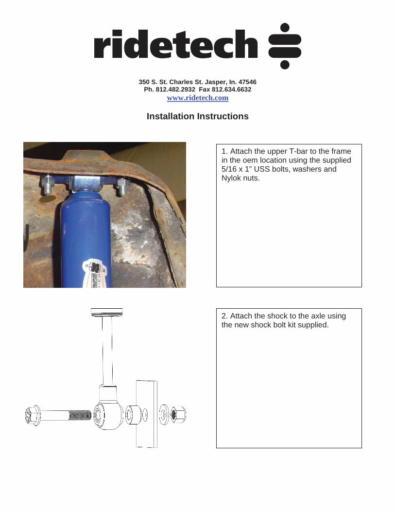
1. Attach the upper T-bar to the frame in the oem location using the supplied 5/16 x 1” USS bolts, washers and Nylok nuts.
2. Attach the shock to the axle using the new shock bolt kit supplied.

350 S. St. Charles St. Jasper, In. 47546 Ph. 812.482.2932 Fax 812.634.6632
www.ridetech.com
Part # 11284499 65-70 Impala Rear Lower StrongArms
For use w/ CoolRide Components:
2 90001027 Lower arm – WW 22.5”
4 90001085 Poly bushing half
2 90001089 Poly bushing half (Rear)
2 90001086 Poly bushing half (Front)
2 90000722 Inner bushing sleeve - 2.625" long x .625" I.D x .75" O.D. (Rear)
2 90000467 Inner bushing sleeve - 2.5" long x .625" I.D. x .75" O.D. (Front)
2 90001092 Tube of Lithium grease
Hardware: 4 99621006 5/8” x 3 ¾” SAE Gr. 8 bolt Upper and lower arms
4 99622006 5/8” SAE Nylok jam nut Upper and lower arms/panhard bar stud

Installation Instructions
1. Clean the bushing surfaces on the frame and axle brackets. Lubricate with the lithium grease supplied. 2. Fasten the StrongArm to the frame and axle using the 5/8” x 3 ¾” bolts and Nylok jam nuts supplied. 3. Fasten the air spring to the lower arm using a 3/8” x 3/4" bolt, flat washer and lock washer supplied w/ the air spring kit.

350 S. St. Charles St. Jasper, In. 47546 Ph. 812.482.2932 Fax 812.634.6632
www.ridetech.com
Part # 11296699 65-66 Impala Rear Upper StrongArm & Panhard Bar Kit
Upper Arm Components: 1 90002850 Upper StrongArm – C-C 12.8125” 1 70013364 R-Joint Rod End housing 1 99752004 3/4”-16 SAE jam nut 4 70013544 R-Joint Spacer – 5/8” ID x 1.031” long Panhard Bar Components: 1 90002827 Panhard bar – TW 33.875” (C-C 35.75”) 1 70013364 R-Joint Rod End housing 1 99752004 3/4”-16 SAE jam nut 1 90000461 Panhard bar axle stud 2 70013334 Axle Stud R-Joint Spacer – 5/8” ID x .620” long 2 70013764 Frame Mount R-Joint Spacers – 9/16” ID x .620” long R-Joint Components 70013279 Retaining Ring 70013280 Wavo Wave Spring 70013276 R-Joint Composite Center Ball Hardware: 2 99621006 5/8” x 3 ¾” SAE Gr. 8 bolt Upper arm 3 99622006 5/8” SAE Nylok jam nut Upper arm / panhard bar stud 1 99561003 9/16” x 3” SAE Gr. 8 bolt Panhard bar to frame 2 99562001 9/16” SAE Nylok jam nut Panhard bar 1 99563001 9/16” USS flat washer Panhard bar stud 1 99603003 5/8” USS flat washer Panhard bar stud
Insert the SMALL end of the spacer INTO each side of the center pivot ball. Push the spacer in until it bottoms out in the center pivot.

Installation Instuctions
New R-Joints will be quite stiff (75-90 in/lbs breakaway torque) until they "break in" after a few miles of use. After the break in period they will move much more freely. Because the composite bearing race contains self-lubricating ingredients, no additional lubrication is needed or desired. Any additional lubrication will only serve to attract more dirt and debris to the R-Joint and actually shorten its life.
1. Replace the factory upper trailing arm with the StrongArms. 5/8” x 3 ¾” bolts and Nylok jam nuts are supplied to replace the factory hardware. A 5/8” ID x 1.031” long spacer will need to be inserted into each side of the R-Joint. Note: Some cars may have two upper arms. In this case you will need to order a second upper arm, part # 11296698
2. Replace the factory panhard bar with the new one using the new stud and hardware supplied. Insert the 5/8” Inside Diameter R-Joint Spacers into the R-joint of one end of the Panhard Bar. Check air spring clearance through full suspension travel. Allowing the air spring to rub will result in failure and is not a warrantable situation.

3. The other end of the Panhard Bar will attach to the frame using the 9/16” x 3” bolt and Nylok nut. Insert the 9/16” Inside Diameter R-Joint Spacers into the R-joint 4. The panhard bar should be approximately 35 ¾” center eye to center eye, but may need adjusted to center the axle. This should be checked at ride height.


