part 1: draft nureg/cr6671 - dispersed flow heat transfer ... · pennstate v department of...
TRANSCRIPT
PENNSTATE
V Department of Mechanical and Nuclear Engineering College of Engineering The Pennsyivania State University
137 Rebei Building
Univer4it\ Park. PA 16802-1412
(814) 865-2519
Fax: (814) 863-4848
January 10, 2001
Mr. David E. Bessette U. S. Nuclear Regulatory Commission RES/DST/RPSB MS-R-10-E 11545 Rockville Pike Rockville, MD 20852-2738
Dear Mr. Bessette:
Enclosed is a copy of PSU ME/NE-NRC-04-98-041 Report, Revision 1. Corrections were made from the memos of May 11, 2000 and November 7, 2000 per Linda Stevenson. If you have any questions, please feel free to contact me.
Sincerely
-.. L. E. Hochreiter Professor Mechanical and Nuclear Engineering
Enclosure
Cc: F. B. Cbeung T. Lin
College of EngineeringAn Equal Opportunity t'niverit.j

PSU ME/NE - NRC-04-98-041 Report 1, Revision 1
Dispersed Flow Heat Transfer Under Reflood Conditions in a 49 Rod Bundle:
Test Plan and Design - Results From Tasks 1-10
L.E. Hochreiter Principal Investigator
Department of Mechanical and Nuclear Engineering
Fan-Bill Cheung Co-Principal Investigator Department of Mechanical and Nuclear Engineering
T.F. Lin Co-Principal Investigator Applied Research Laboratory
A.J. Baratta C. Frepoli
A. Sridharan D.R. Todd
E.R. Rosal (Applied Research Laboratory)
The Pennsylvania State University February 2000

ABSTRACT
This report describes the program objectives of the Rod Bundle Heat Transfer Program as well as the proposed test design, scaling efforts and the integration of the program into the analysis efforts for improving the best-estimate thermal-hydraulic computer codes. The primary area of investigation is the dispersed flow film boiling processes associated with the reflood portion of a large-break Loss of Coolant Accident, A detailed Phenomena Identification Ranking Table was developed for the reflood process in which the phenomena were subdivided into the individual component phenomena, which a best-estimate computer code models or represents. The individual component models are added in the computer code to provide a prediction of the overall wall heat flux as a function of time during the transient. Since the best-estimate computer codes are modeling individual phenomena on a component level, the experiments and the test instrumentation were developed to provide the detailed information such that the modeling could be confirmed. In this manner, the effects of compensating errors in the modeling will be minimized.
A comprehensive review of other experimental programs have been performed as well as the open literature such that the facility design benefits from the previous experimental work. In addition, a detailed scaling analysis was performed of the facility to determine what, if any, distortion effects could be present which could influence the quality of the experimental data. Both a top down and bottom up scaling analysis was performed using the Zuber-Wulff scaling approach which is state-of-the-art for thermal-hydraulic scaling. The Pi groups were calculated for the facility and for a PWR and BWR plant reflood transient and compared. It was found that there is some distortion in the test facility due to material differences of the heater rods relative to nuclear fuel rods, and the radiation heat sink effects of the housing which surround the heater rod bundle. The result was to increase the bundle size, and to investigate the different material types in a separate effects test.
The instrumentation requirements for the facility were driven by the phenomena modeling needs identified in the PIRT. There will be ample instrumentation, as compared to previous tests, to obtain data on void fraction, vapor superheat temperatures in addition to heater rod wall temperatures. In addition, a laser illuminated digital system will be used to measure the entrained droplet size and velocity distributions within the rod bundle. Also, a gamma densitometer will be used to measure the void fraction at fixed locations to compare with the void fraction data from the differential pressure cells. A conceptual design for the test facility has been developed along with a detailed instrumentation plan which addresses the phenomena which was identified in the PIRT. There are over 400 channels of instrumentation for the facility.
The RBHT facility is a unique facility which will provide new data for the fundamental development of best-estimate computer code models. This effort will reduce the uncertainty in the NRC's thermal-hydraulic computer codes which will enhance the understanding of the complex two-phase phenomena which is modeled for the reflood transient.
iii

TABLE OF CONTENTS
A b stract ...................................... ............................................................... iii List of Figures .............................................................................................. x List of Tables ................................................................................................ xiv
Acknowledgments ........................................................................................... xl
Executive Summary ................................................................................................................... xvii
1. Introduction ............................................................................................................................. 1-1 1-1 Background .............................................................................................................. 1-1 1.2 Program Objectives .................................................................................................. 1-10 1.3 Products from the Rod Bundle Heat Transfer Program ........................................... 1-13 1.4 Technical Approach ................................................................................................. 1-13 1.5 References ................................................................................................................ 1-15
2. Rod Bundle Heat Transfer Program Phenomena Identification and Ranking Table (PIRT) .. 2-1 2.1 Introduction/Background ............................................................................................ 2-1 2.2 Preliminary PIRT for the Rod Bundle Heat Transfer Tests - PWR Phenomena ........ 2-3
2.2.1 Introduction ................................................................................................. 2-3 2.2.2 Development of the Classifications for the Different Regions for the Rod
Bundle Heat Transfer Program " Preliminary PIRT ....................................... 2-4 2.3 PIRT for Rod Bundle Heat Transfer Tests -BWR Reflood Phenomena .................. 2-24
2.3.1 Introduction .............................................................................................. 2-24 2.3.2 BW R Reflood Phenomena of Interest ....................................................... 2-24
2.4 Conclusions ............................................................................................................ 2-28 2.5 References ............................................................................................................... 2-28
3. Literature Review ...................................................................................................................... 3-1 3.1 Introduction ................................................................................................................ 3-1 3.2 Rod Bundle Tests ...................................................................................................... 3-1 3.3 Single-Tube Tests and Related Studies ..................................................................... 3-8
3.3.1 Liquid Entrainment and Breakup ................................................................ 3-8 3.3.2 Drop Size Distribution and Number Density ............................................ 3-10 3.3.3 Droplet Velocity, Interfacial Shear, and Interactions ................................ 3-11 3.3.4 Droplet-Enhanced Heat Transfer ............................................................... 3-12 3.3.5 Droplet Evaporative Heat Transfer ........................................................... 3-13 3.3.6 Direct Contact Heat Transfer .............................. 3-14 3.3.7 Total W all Heat Transfer ........................................................................... 3-15 3.3.8 Effects of Spacer Grids .............................................................................. 3-16 3.3.9 Effects of Inlet Flow Oscillation and Thermal Nonequilibrium ............... 3-16
3.3.10 Other Factors ....................................................................................................... 3-17 3.4 Master Table: Previous Studies Relevant to the High-Ranking Phenomena
Identified in the PIRT for the RBHT Program ................................................... 3-24 3.5 References ................................................................................................................ 3-26
3.5.1 Single Tube Tests and Related Studies ..................................................... 3-26 3.5.2 Rod Bundle Tests ...................................................................................... 3-49
V

4. Define Information Needed for New Code Modeling Capabilities, Validation, and
Assessment ..................................................................................................................... 4-1
4.1 Introduction ................................................................................................................ 4-1
4.2 Brief Review of Heat Transfer Models Used in Best-Estimate Codes for Reflood ..4-2
4.2.1 RELAP5/M OD3 .......................................................................................... 4-2
4.2.1.1 Introduction ............................................................................................... 4-2
4.2.1.2 RELAP5/M OD3 Heat Transfer Package ................................................... 4-4
4.2.1.3 Conclusions ............................................................................................... 4-8
4.2.2 TRAC-BF 1 Reflood M odel .................................................................................. 4-10
4.2.2.1 Introduction ............................................................................................. 4-10
4.2.3 TRAC-PF 1 Reflood M odel ............................................................................... 4-11
4.2.3.1 Introduction ............................................................................................ 4-11
4.2.4 COBRA-TF Code ................................................................................................. 4-26
4.2.4.1 Introduction ............................................................................................ 4-26
4.2.4.2 COBRA-TF Heat Transfer Package ........................................................ 4-27
4.3 Road Map from the PIRT, to the Code Models, to the Test Instrumentation
and Data Analysis ............................................................................................... 4-46
4.3.1 Single Phase Liquid Convection Below the Quench Front ....................... 4-46
4.3.2 Subcooled and Saturated Boiling Below the Quench Front ...................... 4-50
4.3.3 Quench Front Behavior ............................................................................. 4-55
4.3.4 Two-Phase Froth Region for the Core Component ................................... 4-63
4.3.5 Dispersed Flow Film Boiling Region ........................................................ 4-69
4.3.6 Top Down Quench in Core Components .................................................. 4-74
4.3.7 Other effects: spacer grids, housing .......................................................... 4-76
4.4 Conclusions ............................................................................................................. 4-76
4.5 References ............................................................................................................... 4-77
5. Rod Bundle Heat Transfer Program Objectives and Facility Mission ................................. 5-1
5.1 Introduction ........................................................................................................ 5-1
5.2 Rod Bundle Heat Transfer Program Objectives ......................................................... 5-1
5.3 Conclusions ............................................................................................................... 5-5
6. First Tier Scaling for the Rod Bundle Heat Transfer Test Facility ......................................... 6-1
6.1 Introduction ........................................................................................................ 6-1
6.2 Two Tier Scaling Approach ....................................................................................... 6-2
6.3 Application of the Top-down Scaling Approach ........................................................ 6-2
6.3.1 Fluid Energy Equation ..................................................................................... 6-3
6.3.2 Heater Rod (Fuel Rod) Energy Equation Scaling ......................................... 6-24
6.3.3 Momentum Equation Scaling for the Rod Bundle Heat Transfer
Test Facility ................................................................................................... 6-32
6.4 Calculation of Pi Groups for Flow Energy Equation ............................................... 6-48
6.4.1 Introduction ................................................................................................... 6-48
6.4.2 Calculation of Convective Heat Transfer Pi Groups ..................................... 6-48
6.4.2.1 M ethodology Used for Calculations ................................................. 6-49
6.4.2.2 Numerical Input Quantities .............................................................. 6-50
vi
6.4.2.3 Num erical Values of the Convection .Pi- Groups .............................. 6-51
6.4.3 Quench Energy Groups ............................... .... .................................... 6-54
6.4.4 Thermal Radiation Heat Transfer Pi Group Calculations ............................. 6-57
6.4.5 Summ ary ....................................................................................................... 6-66
6.5 Calculations of Pi Groups for the Rod Energy Equation ........................................ 6-71
6.5.1 Introduction ................................................... -'"' .......................................... 6-71
6.5.2 Convection and Stored Energy Pi Groups.. .......:,:: ........................................ 6-71
6.5.3 Therm al Radiation Heat Transfer Pi Groups.-...... : ........................................ 6-75
6.5.4 Summ ary ................................................... ; . ... ......................................... 6-79
6.6 Calculation of Pi Groups for Flow M om entum Equation ....................................... 6-83
6.7 Calculation of PW R and BW R Pi Groups .................... ...................................... 6-85
6.7.1 Introduction ................................................................................................... 6-85
6.7.2 Calculation of Pi Groups for PW R ................ ....................................... 6-85
6.7.3 Calculation of Pi Groups for BW R .............. :.:............................................. 6-86
6.8 Conclusions .............................................................. :::: ....................................... 6-88
6.9 References ......... ........................................ 6-91
6.10 Nom enclature ............................................... t ........ ........................................ 6-92
7. Second Tier Scaling for the Rod Bundle Heat Transfer Test Facility ...................................... 7-1
7.1 Introduction ................................................. 7-1
7.2 Housing Effects and Studies ........... -........................... 7-2
7.2.1 Introduction ..... ......................................... :.:................................................7-2
7.2.2 Results .................................................................................................... 7-3
7.3 M aterial Differences .................................................. :: .............................................. 7-6
7.3.1 Introduction ........................................ ..... ..................................... 7-6
7.3.2 Rod Com parison ............................................ ..................................... 7-7
7.4 Surface Properties Differences ................................... '..:. ............................................ 7-8
7.5 Scaling Conclusions ................................................ .......................................... 7-8
7.6 References ................................................. 7-10
8. Instrumentation Requirements for Rod Bundle Heat Transfer Facility .................................... 8-1
8.1 Introduction ............................................................... v...... : ........................................... 8-1
8.2 Instrum entation Requirem ents ..................................-. : ........................................... 8-1
8.3 Proposed New Instrum entation ................................. '.':: ............................................. 8-5
8.4 Instrum entation Plan Com parison to the PIRT .......................................................... 8-6
8.5 Conclusions ................................................................ .......................................... 8-7
8.6 References ................................................................................................................ 8-7
9. Developing a Facility Input M odel ...................................... v..... :-- ............................................ 9-1
9.1 Introduction ................................................................. ::............................................... 9-1
9.2 Two-Channel M odel ..................................................... ::- ............................................ 9-1
9.2.1 Input Deck Description .......................... :.*..:.:..: ............................................ 9-1
9.2.2 Results of Two-Channel M odel ............... ............................................ 9-2
9.3 Individual Sub-Channel M odel ............................. "....-:::: .......................................... 9-4
9.3.1 Input Deck Description ............... :.- .................... 9-4
vii

9.3.2 Results of Sub-Channel M odel ................................................................... 9-5
9.4 Conclusions .............................................................................................................. 9-6
9.5 References ................................................................................................................. 9-7
10. Rod Bundle Heat Transfer Test M atrix ................................................................................ 10-1 10.1 Introduction ............................................................................................................ 10-1
10.2 Types of Tests W hich are Proposed ....................................................................... 10-1
10.3 Range of Conditions Considered for the Experiments .............. ....................... 10-4
10.4 Proposed Preliminary Test M atrix ......................................................................... 10-5
10.5 Conclusions ........................................................................................................... 10-8
10.6 References ............................................................................................................ 10-10
11. Test Facility Design (Task 10) ............................................................................................. 11-1
11.1 Introduction ............................................................................................................ 11-1
11.2 General Design Description ................................................................................... 11-1
11.3 D etailed Com ponent Design Description ............................................................... 11-1
11.3.1 Test Section ............................................................................................. 11-1
11.3.2 Lower Plenum ......................................................................................... 11-3
11.3.3 Upper Plenum .......................................................................................... 11-4
11.3.4 Carryover Tanks ...................................................................................... 11-4
11.3.5 Steam Separator and Collection Tanks ................................................... 11-5 11.3.6 Pressure Oscillation D am ping Tank........................................................ 11-5
11.3.7 Exhaust Piping ......................................................................................... 11-5
11.3.8 Injection W ater Supply Tank .................................................................. 11-6
11.3.9 W ater Injection Line ................................................................................ 11-6
11.3.10 Steam Supply ......................................................................................... 11-6
11.3.11 Droplet Injection System ....................................................................... 11-7
11.4 Test Facility Instrum entation .................................................................................. 11-7 11.4.1 Loop Instrum entation and Controls ........................................................ 11-7
11.4.2 Test Section Instrum entation ................................................................... 11-9
11.4.3 D ata Acquisition System ....................................................................... 11-13
11.5 RBHT Test Facility Improvem ent ........................................................................ 11-14
11.6 Conclusions ......................................................................................................... 11-15
11.7 References ........................................................................................................... 11-15
12. Conclusions .......................................................................................................................... 12-1
Appendix A: Literature Review A-i: FLECHT Low Flooding Rate Cosine Test Series ................................................ A l-1 A-2: FLECHT Low Flooding Rate Skewed Test Series .............................................. A2-1
A-3: Westinghouse FLECHT-SEASET 21 Rod Bundle Test Facility .......................... A3-1
A-4 FLECHT-SEASET 161 Rod Unblocked Bundle Tests ......................................... A4-1
A-5 FEBA Flooding Experiments With Blocked Arrays ......................................... A5-1 A-6 Oak Ridge national Laboratory Thermal-Hydraulic Test Facility ......................... A6-1
A-7 FRIGG-2 36-Rod Loop (Sweden) ........................................ ............................ A7-1
A-8 GE 9 Rod Bundle Facility ..................................................................................... A8-1
viii

A-9 NRU Experiments ................................................................................................. A9-1
A-10 ACHILLES Reflood Heat Transfer Tests ..................................................... A10-1
A-11 Lehigh 9-Rod Bundle Tests .......................................................................... Al1-1 Appendix B: Radiation Heat Transfer Network and Calculation of Pi Groups ..................... B-1
Appendix C: Bundle Model Description .............................................................................. C-1
Appendix D: COBRA-TF Listings ......................................................................................... D-1
ix
List of Figures
1-1 Reflood Flow Regimes for High and Low Reflood Rates ......................................... 1-4 1-2 Detailed Low Flooding Rate Reflood Flow Regimes ................................................. 1-5 1-3 Transition and Quench Fronts for FLECHT-SEASET Test 31504 (Reference 3) ..... 1-6 1-4 Entrainment Behavior for Rod Bundle Reflooding .................................................... 1-7 1-5 Heat and Mass Transfer Mechanism in Dispersed Flow Film Boiling (From
R eference 1-2) ............................................................................................ 1-9 1-6 Comparison of Current Best Estimate Calculated PCTs with CSAU Study1 -5).. 1-12 2-1 Code Scaling, Applicability and Uncertainty (CSAU) Evaluation Methodologyog
2-2 2-2 Froth Region and Quench Front Locations for Reflood ........................................ 2-7 2-3 Froth Front and Quench Front Curves for FLECHT-SEASET Run 31203,
1.5 in/sec, 40 psia T est ............................................................................... 2-8 2-4 Froth Front and Quench Front Curves for FLECHT-SEASET Run 31504,
1.0 in/sec, 40 psia Test ............................................................................... 2-9 2-5 Typical Conditions in Rod Bundle During Reflood ............................................ 2-10 4-1 RELAP 5/MOD 3 Vertical Flow Regime Map ...................................................... 4-3 4-2 RELAP 5 Wall Heat Transfer Flow Chart ............................................................. 4-6 4-3 Void-fraction Superheat Plane ............................................................................. 4-13 4-4 Flow-regime Map During Reflood ...................................................................... 4-15 4-5 HTC Correlation Selection Logic ........................................................................ 4-16 4-6 HTC Correlation Selection Logic ........................................................................ 4-17 4-7 HTC Correlation Selection Logic ........................................................................ 4-18 4-8 HTC Correlation Selection Logic ........................................................................ 4-19 4-9 HTC Correlation Selection Logic for Reflood Model ......................................... 4-20 4-10 HTC Correlation Selection Logic for Reflood Model ......................................... 4-21 4-11 HTC Correlation Selection Logic for Reflood Model ......................................... 4-22 4-12 Hot Wall Flow Regimes ...................................................................................... 4-33 4-13 Hot Wall Flow Regime Selection Logic .............................................................. 4-34 4-14 Schematic Representation of Boiling Curve ........................................................ 4-35 4-15 Heat Transfer Regime Selection Logic ................................................................ 4-36 4-16 WCOBRA/TRAC Heat Transfer Regime Map ....................... 4-38 4-17 Two-Phase Enhancement: Comparison of Models and Reflood Data ................. 4-40 4-18 Radiation Heat Flux Network .............................................................................. 4-43 4-19 D roplet B reakup ................................................................................................... 4-44 4-20 Shattered Droplet Size from Heated Grid Straps ................................................. 4-45 6-1 Mass Balance FLECHT-SEASET Run 31504 .................................................... 6-30 6-2 R B H T L ayout ....................................................................................................... 6-54 6-3 Six Node Radiation Network ............................................................................... 6-55
X

6-4 Four N ode Radiation N etwork ............................................................................. 6-60
6-5 PW R B undle ........................................................................................................ 6-79
6-6 B W R B undle ........................................................................................................ 6-82
7-1 Convective Heat Transfer Coefficient (FLECHT-SEASET Run 31504) ............ 7-11
7-2 Wall Surface Temperature in the 7 x 7 Bundle (Base Case) ............................... 7-11
7-3 Heat Rate To and From the'Housing in the 7 x 7 Bundle (Base Case)
(Bundle Linear Power = 103000 W/m) ................................................... 7-12
7-4 Heat Rate To and From the Housing in the 7 x 7 Bundle (Base Case)
(Bundle Linear Power = 103000 W/m) ................................................... 7-12
7-5 Clad Temperature Drop in the Inner 3 x 3 Array Because of Radiative
Heat Transfer in a Finite Size Bundle Array ............................................ 7-13
7-6 Inner 3 x 3 Rod Array Clad Temperature Bias in the RBHT Bundle
H ousing Thickness Sensitivity ................................................................. 7-13
7-7 Inner 3 x 3 Rod Array Clad Temperature Bias in RBHT Bundle Housing Initial (Pre-heating) Temperature Sensitivity ............................ 7-14
7-8 Inner 3 x 3 Rod Array Clad Temperature Bias in RBHT Bundle W all Em issivity Sensitivity ...................................................................... 7-14
7-9 Inner 3 x 3 Rod Array Clad Temperature Bias in the RBHT Bundle Radial Power Distribution Sensitivity ..................................................... 7-15
7-10 Inner 3 x 3 Rod Array Clad Temperature Bias in the RBHT Bundle D um m y Rods Effect ................................................................................ 7-15
7-11 Steady-State Temperature Profile ........................................................................ 7-16
7-12 Electrical Rod Steady-State Temperature Profile Gap Resistance Sensitivity .... 7-16
7-13 R od Q uenching .................................................................................................... 7-17
7-14 Rod Quench Energy Release ................................................................................ 7-17
7-15 Distribution of Measured Rewet Temperature During Westinghouse G-1
and G-2 Blowdown Rod Bundle Experiments .................................................... 7-18
9-1 RBHT - Partitioning of Sections, Channels & Gaps .............................................. 9-8
9-2 RBHT - Test Section 7 x 7 Rod Bundle Array Cross Section ............................... 9-9
9-3 RBHT Heater Rod - Radial Dimensions, Materials & Nodding Scheme ............ 9-10
9-4 RBHT - Radial Dimensions, Materials & Noding Scheme ................................. 9-11
9-5 RBHT - Axial Dimensions & Nodal Scheme ...................................................... 9-12
9-6 A xial Pow er Shape ............................................................................................... 9-13
9-7 Pow er D ecay ........................................................................................................ 9-13
9-8 Quench Front 1.0 in/sec Reflooding Rate ............................................................ 9-14
9-9 Hot Rod Clad Temperature 2.54 cm/sec (1.0 in/sec) Reflooding Rate ......... ' ..... 9-15
9-10 Housing Temperature 2.54 cm/sec 1.0 in/sec Reflooding Rate ........................... 9-15
9-11 Hot Rods Clad Temperature 2.54 cm/sec (1.0 in/sec)Reflooding Rate ............... 9-16
9-12 Vapor Temperature 2.54 cm/sec (1.0 in/sec) Reflooding Rate ............................ 9-16
9-13 Vapor Flow Rate at Outlet of Rod Bundle 2.54 cm/sec (1.0 in/sec) R eflooding R ate ....................................................................................... 9-17
9-14 Entrainment Flow Rate at Outlet of Rod Bundle 2.54 cm/sec (1.0 in/sec) R eflooding R ate ....................................................................................... 9-17
xi

9-15 Pressure at Inlet of Rod Bundle 1.0 in/sec Reflooding Rate ............................... 9-18
9-16 Vapor Reynold's Number 2.032 cm/sec (0.8 in/sec) Reflooding Rate ............... 9-19
9-17 Vapor Reynold's Number 2.54 cm/sec (1.0 in/sec) Reflooding Rate ................. 9-20
9-18 Vapor Reynold's Number 3.81 in/sec (1.5 in/sec) Reflooding Rate ................... 9-20
9-19 Nodal Diagram for a Sub-Channel Model ........................................................... 9-21
9-20 Axial Nodal Diagram for Sub-Channel Model ................................................... 9-22
9-21 Temperature Distributions-After 50 sec. Heatup (in 'C) ..................................... 9-23
11-1 RBHT Test Facility Schematic .......................................................................... 11-17
11-2 Test Section Isometric View ............................................................................. 11-18
11-3 Rod Bundle Cross Sectional View .................................................................... 11-19
11-4 H eater R od ......................................................................................................... 11-20
11-5 Heater Rod Axial Power Profile ........................................................................ 11-21
11-6 Low-Melt Reservoir .......................................................................................... 11-22
11-7 Low Mass Flow Housing Assembly .................................................................. 11-23
11-8 Housing Window ............................................................................................... 11-24
11-9 Low er Plenum ................................................................................................... 11-25
11-10 Lower Plenum Flow Battle ................................................................................ 11-26
11-11 U pper Plenum .................................................................................................... 11-27
11-12 Exhaust Line Baffle ........................................................................................... 11-28
11-13 Large Carryover Tank ........................................................................................ 11-29
11-14 Small Carryover Tank ....................................................................................... 11-30
11-15 Steam Separator ................................................................................................. 11-31
11-16 Steam Separator Collection Tank ...................................................................... 11-32
11-17 Pressure Oscillation Damping Tank .................................................................. 11-33
11-18 Injection Water Supply Tank ............................................................................. 11-34
11-19 Droplet Injection Schematic .............................................................................. 11-35
11-20 Loop Instrumentation Schematic ....................................................................... 11-36
11-21 Rod Bundle and Housing Instrumentation Axial Locations .............................. 11-37
11-22 Instrumentation Heater Rod Radial Locations .................................................. 11-38
11-23 Traversing Steam Probe Rake ........................................................................... 11-39
11-24 Densitometer Schematic .................................................................................... 11-40
11-25 Digital Camera and Laser Instrumentation ........................................................ 11-41
Al-i FLECHT Low-Flooding Rate Test Configuration ......................................... A1-5
A1-2 Rod Bundle Instrumentation for FLECHT Low-Flooding Rate Tests ....... A1-6
A2-1 FLECHT Low Flooding Rate Test Facility Schematic ...................................... A2-5
A2-2 FLECHT Low Flooding Rate Test Power Shape ............................................... A2-6
A2-3 FLECHT Low Flooding Rate Test Rod Bundle Cross Section .......................... A2-7
A3-1 Rod Bundle Flow Blockage Task Instrumentation Schematic D iagram .................................................................................................. A 3-2
A4-1 FLECHT-SEASET Rod Bundle Cross Section .................................................. A4-7
A4-2 FLECHT-SEASET Facility Flow Diagram ........................................................ A4-8
A5-1 Test Facility ................................................................................................... A5-3
A5-2 Axial Power Profile ........................................................................................ A5-4
A5-3 Upper Bundle End and Upper Plenum .......................................................... A5-5
xii

A5-4 Rod Bundle, Test Matrix for Series I Through VIII ........................................... A5-6
A5-5 Rod Geometry and Location of Thermocouple ............................... A5-7
A5-6 Radial and Axial Location of Cladding, Fluid and Housing
TC 's for Test Series I .............................................................................. A 5-8
A5-7 Axial Locations of Various Thermocouples in 5X5
R od B undle ............................................................................................. A 5-9
A5-8 Rod Row: Comparison of Different Fluid Temperature Measuring D evices ............................................................................................ A 5-10
A6-1 THTF System With Instrumented Spool Pieces Labeled ................................... A6-2
A6-2 Identification of THTF Heater Rods, Subchannel Location, and
Inactive Rods in THTF Heater Bundle ................................................... A6-3
A6-3 Cross-section of a Typical FRS .......................................................................... A6-4
A6-4 Axial Location of Spacer Grid and FRS Thermocouples ................................... A6-5
A7-1 36-Rod Bundle of the FRIGG-2 ......................................................................... A7-3
A7-2 Flow Diagram of the FRIGG-2 Loop .................................................................. A7-4
A8-1 Positions of Pressure Taps for Setting Isokinetic Conditions ............................. A8-3
A8-2 Schematic of Loop Showing Sampling Circuit .................................................. A8-4
A9-1 Schematic of NRU Loss-of-Coolant Accident Test Train .................................. A9-2
A9-2 NRU Reactor Core Configuration ...................................................................... A9-3
A9-3 Instrumentation Levels in the TH-2 Test Assembly ........................................... A9-4
A9-4 Instrumentation Levels in the TH-3 Test Assembly ........................................... A9-5
A10-1 Cross Section of ACHILLES 69-Rod Bundle .............................................. A10-7
A10-2 Schematic of ACHILLES Flow Loop .......................................................... A10-8
A10-3 Axial Locations in Test Section ......................... ........................................ A10-9
A11-1 Cross-sectional View of Test Bundle ............................................................... Al 1-3
Al 1-2 Schematic of Test Section Support System ...................................................... A11-4
Al 1-3 Sample Plot of Temperature and Steam Quality Data for the
Stabilized Quench Front Experiments .................................................. Al 1-5
Al 1-4 Sample Plot of Heat Flux and Steam Quality Data for the Advancing
Quench Front Experiments ................................................................. All-10
Al 1-5 Sample Plot of Rod and Steam Temperature Data for the Advancing
Quench Front Experim ents ................................................................. A l1-11
Al 1-6 Typical Transverse Vapor Temperature Profile for
V arious Vapor Qualities ..................................................................... A l1-12
Al 1-7 Typical Transverse Vapor Temperature Profiles Downstream
O f the G rid Spacer ............................................................................. A l1 -13
A11-8 Comparison of Transverse Vapor Temperature Profiles Upstream
and Downstream of the Grid Spacer ................................................... Al1-13
Xiii
List of Tables
2-1 Single Phase Liquid Convective Heat Transfer .............................................................. 2-11 2-2 Subcooled and Saturated Boiling --The Core Component Below the
Q uench F ront ...................................................................................................... 2-13 2-3 Q uench F ront ................................................................................................................. 2-15 2-4 Two-Phase Froth (Transition) Region for Core Component .......................................... 2-17 2-5 A Dispersed Flow Region .............................................................................................. 2-18 2-6 Top D ow n Q uench ......................................................................................................... 2-21 2-7 Preliminary PIRT for Gravity Reflood Systems Effects Tests ....................................... 2-22 2-8 High Ranked BWR Core Phenomena ............................................................................ 2-26 3-1 Comparison of the Data From Various Rod Bundle Tests ............................................... 3-5 * Master Table: Previous Studies Relevant to the High-Ranking Phenomena
During the Reflood Stage of a Large Break LOCA ............................................ 3-18 4-1 RELAP5/MOD3 3 Heat Transfer Modes ......................................................................... 4-5 4-2 Summary of interfacial areas and heat transfer coefficients ............................................. 4-9 4-3 TRAC-PF1/MOD2 Heat Transfer Regimes ................................................................... 4-14 4-4 Weighting factors of reflood interfacial heat-transfer models ........................................ 4-23 4-5 Interfacial Heat transfer Area Per Unit Volume ............................................................. 4-28 4-6 Single Phase Liquid Convective Heat Transfer in the Core Component During
Reflood Below the Quench Front ....................................................................... 4-47 4-7 Subcooled and Saturated Boiling -The Core Component Below the
Q uench Front ...................................................................................................... 4-5 1
4-8 Quench Front Behavior in the Core Component ............................................................ 4-56 4-9 Two-Phase Froth (Transition) Region for Core Component .......................................... 4-64 4-10 A Dispersed Flow Region for Core Component ............................................................ 4-70 4-11 Top Down Quench in Core Components ....................................................................... 4-75 6-1 Normalizing Factors for Fluid Energy Equation .............................................................. 6-9 6-2 List of Initial Conditions and Assumptions .................................................................... 6-10 6-3 PW R C om parisons ......................................................................................................... 6-20 6-4 B W R C om parisons ......................................................................................................... 6-22 6-5 Normalization Factors for Rod Energy Equation ........................................................... 6-24 6-6 Normalizing Factors for Fluid Momentum Equation ..................................................... 6-37 6-7 Pi Groups for Fluid Energy Equation ............................................................................. 6-41 6-8 RBHT Program Conditions ............................................................................................ 6-48 6-9 Reference Conditions for the Fluid Energy Equation Pi Groups ................ 6-49 6-10 M aterial Properties ......................................................................................................... 6-54 6-11 Electrical R od G eom etry ................................................................................................ 6-54 6-12 Nuclear Rod Geometry for PWR ................................................................................... 6-55 6-13 Nuclear Rod Geometry for BWR ................................................................................... 6-55 6-14 Numerical Values of Pi Groups - Fluid Energy Equation .............................................. 6-68 6-15 Reference Conditions for-Rod Energy Equation Pi Groups ........................................... 6-71 6-16 Comparison of Calculated Time Constants .................................................................... 6-73
xiv

6-17 Convection and Stored Energy Pi Groups for Electrical/Nuclear Rod .......................... 6-75
6-18 Numerical Values of Pi Groups - Rod Energy Equation ................................................ 6-80
6-19 Fluid M om entum Pi Groups ........................................................................................... 6-83
6-20 Numerical Values of Pi Groups - Fluid Momentum Equation ....................................... 6-84
7-1 Input data .......................................................................................................................... 7-3
7-2 Input data .......................................................................................................................... 7-7
8-1 Single Phase Liquid Convective Heat Transfer in the Core Component During Reflood Below the Quench Front .......................................................... 8-10
8-2 Subcooled and Saturated Boiling - Core Component Below the Q uench Front ................................................................................................ 8-12
8-3 Quench Front Behavior in the Core Component ............................................................ 8-15
8-4 Two-Phase FROTH (Transition) Region for Core Component ..................................... 8-18
8-5 A Dispersed Flow Region for Core Component ............................................................ 8-20
8-6 Top Down Quench in Core Components ....................................................................... 8-24
8-7 Preliminary PIRT for Variable Reflood Systems Effects Tests ..................................... 8-26
8-8 High Ranked BWR Core Phenomena ............................................................................ 8-28
9-1 Weber Number Parameter at 425 Seconds ....................................................................... 9-4
10-1 Range of PWR Reflood Conditions ............................................................................... 10-9
11-1 G eneral Specifications .................................................................................................. 11-42
11-2 Therm ocouple Specifications ....................................................................................... 11-43 11-3 Instrumentation and Data Acquisition Channel List .................................................... 11-44
A3-5 Assessment of FLECHT-SEASET Unblocked 21-Rod Bundle Test to RBHT PIRT: A Dispersed Flow Region for Core Component ..................................... A3-5
A3-6 Assessment of FLECHT-SEASET Unblocked 21-Rod Bundle Test to RBHT PIRT: Top Down Quench in Core Components ............................................... A3-6
A3-7 Assessment of FLECHT-SEASET Unblocked 21-Rod Bundle test to RBHT PIRT: Preliminary PIRT for Gravity Reflood Systems. E ffects T ests ...................................................................................................... A 3-7
A3-8 Assessment of FLECHT-SEASET Unblocked 21-Rod Bundle Test fo RBHT PIRT: High Ranked BWR Core Phenomena ..................................................... A3-8
A4-1 FLECHT SEASET Unblocked Bundle Reflood Test Data Summary .......................... A4-9
A5-1 Assessment of FEBA Test to RBHT PIRT: Single Phase Liquid Convective Heat Transfer in the Core Component During Reflood Below the Q uench Front ....................................................................................... A 5-11
A5-2 Assessment of FEBA Test to RBHT PIRT: Subcooled and Saturated Boiling The Core Component Below the Quench Front ............................................. A5-12
A5-3 Assessment of FEBA Tests to RBHT PIRT: Quench Front Behavior In the Core Com ponent .................................................................................. A 5-13
A5-4 Assessment of FEBA Tests to RBHT PIRT: FROTH Region for Core Com ponent ......................................................................................... A 5-15
A5-5 Assessment of FEBA Tests to RBHT PIRT:A Dispersed Flow Region for C ore Com ponent ........................................................................................ A 5-16
A5-6 Assessment of FEBA Tests to RBHT PIRT: Top Down Quench in Core Com ponents ................................................................................... A 5-18
xv

A5-7 Assessment of FEBA Tests to RBHT: Preliminary PIRT for Gravity Reflood System s Effects Tests ........................................................................ A5-19
A5-8 Assessment of FEBA Tests to RBHT PIRT for High Ranked BW R Core Phenom ena ................................................................................... A 5-20
A6-5 Assessment of ORNIJT'HTF Data to RBHT PIRT: Dispersed Flow Region for Core Com ponent ............................................................................. A 6-8
A7-1 Assessment of FRIGG-2 36-Rod Bundle Test to RBHT PIRT: Single Phase Liquid Convective Heat Transfer in the Core Component During Reflood Below the Quench Front ...................................................................... A7-7
A7-2 Assessment of FRIGG-2 36-Rod Bundle Tests to RBHT PIRT: Subcooled and Saturated Boiling in the Core Conmponent Below the Quench F ront .................................................................................................................. A 7-8
A7-3 Assessment of FRIGG-2 36-Rod Bundle Tests to RBHT PIRT for High Ranked BW R Core Phenomena ........................................................................ A7-9
A8-1 Assessment of General Electric 9-Rod Bundle Tests to RBHT PIRT: Subcooled and Saturated Boiling in the Core Component Below the Q uench Front ............................................................................................... A 8-6
A8-2 Assessment of General Electric 9-Rod Bundle Tests to RBHT PIRT for High Ranked BWR Core Phenomena ............................................................... A8-7
A9-1 Measured Conditions for the TH-2 Experiment (1) ........................................................ A9-6 A9-2 Measured Conditions for the TH-3 Experiment ............................................................ A9-8 A9-5 Assessment of NRU Inpile Reflood Data to RBHT PIRT: Dispersed
Flow Region for Core Component .................................................................... A9-9 A9-8 Assessment of NRU Inpile Reflood Data to RBHT PIRT for High
Ranked BW R Core Component ...................................................................... A9-11 A10-1 Summary of Low Flooding Rate Reflood Experiments ........................................ AIO-10 A10-2 Droplet Distribution Experiments ........................................................................ A10-11 A1O-3 Airflow and Voidage Distribution Experiments ....................................................... A1O-12 A10-4 Summary of Best Estimate-Reflood Experiments ..................................................... A1O-13 Al 1-1 Sample Tabulation of a Stabilized Quench Front Data Point ..................................... Al 1-6 Al1-2 Definition of Parameters Used in Table Al1-1 ........................................................... All-7 Al 1-3 Sample Tabulation of an Advancing Quench Front Data Point ............................. Al1-8 Al 1-4 Definition of Parameters Used in Table Al 1-3 ...................................................... Al1-9
xvi

EXECUTIVE SUMMARY
A research program entitled, "Rod Bundle Heat Transfer (RBHT)," funded by the US Nuclear
Regulatory Commission, was initiated at Penn State on November 3, 1997 to develop a Rod
Bundle Heat Transfer Facility and to conduct experiments to aid in the development of reflood
heat transfer models which could be used in the NRC's thermal-hydraulics computer codes. The
RBHT program consists of the following sixteen major tasks:
"* Task 1 - Development of a Preliminary Phenomena Identification and Ranking Table
"* Task 2 - Critical Review of Existing Experimental Data Base
"* Task 3 - Defining Information Needed for New Code Modeling Capabilities, Validation,
and Assessment "* Task 4 - Defining the Program Objectives and Facility Mission
"* Task 5 - First Tier Scaling for the Experimental Facility
"* Task 6 - Second Tier Scaling Analysis for the Local Phenomena
"* Task 7 - Defining the Instrumentation Requirements
"* Task 8 - Developing Facility Input Model "* Task 9 - Drafting a Test Matrix
"* Task 10 - Test Facility Design
"* Task 11 - Construction and Characterization of the RBHT Facility
"* Task 12 - Definition of Test Initial and Boundary Conditions
"* Task 13 - Performing Tests and Qualifying the Test Data
"* Task 14 - Analyzing the Test Data
"* Task 15 - Assessing New or Modified Models
"* Task 16 - Final Model Description, Implementation, and Scaling Report
This report describes the results obtained in the initial phase of the program, i.e., Tasks 1 through
10. It is written for NRC review purpose to insure that the course of the program is properly
directed and that the RBHT Facility is adequately designed, consistent with the NRC model
development and improvement efforts which are underway.
This report, the program objectives, test design, and the test and analysis approach, was
also peer reviewed by individuals who are very knowledgeable and have significant expertise in
the heat transfer and Two-Phase flow area. The individuals were selected by the Nuclear
Regulatory Commission. The comments made by the different individuals were incorporated
into the report as well as into the planning, design, and analysis plans for the Rod Bundle Heat
Transfer Program. In addition, there was also a specific Instrumentation Peer Review Meeting in
which the facility instrumentation plan was reviewed with specialists in Two-Phase flow testing
and instrumentation to provide guidance, comments, and critique of the proposed
instrumentation for the Rod Bundle Heat transfer Program. Again, the comments and ideas
provided by the Peer Review Panel were factored into the instrumentation design, testing
methods and the resulting data analysis.
An introduction, providing the pertinent background information to justify the needs for and the
significance of conducting the RBHT program, is given in Section 1 of the report.
xvii
Section 2 presents a preliminary reflood-heat-transfer specific Phenomena Identification and Ranking Table (PIRT) developed under Task 1 using the same ranking methodology as that employed by Los Alamos, Brookhaven and Idaho National Laboratories, and the NRC. Separate preliminary PIRTs are provided for each of the important reflood regions such that the particular reflood phenomena for a given region could be subdivided into specific component models and phenomena for which a computer code would be used to perform the calculation. The relative rankings listed in these PIRTs clearly indicate the most important reflood phenomena which a best-estimate computer code should simulate with high accuracy. They also serve as a guide in the execution of the subsequent Tasks set forth in the program.
Section 3 describes the results of a comprehensive review of the literature on reflood heat transfer performed under Task 2. Unique information from the available rod bundle data and selective tube data useful to address the phenomena identified in the PIRTs is gathered and then subdivided into several different classifications to indicate which information can be used for each specific type of phenomena. A master cross-reference table is constructed identifying the data source for the highly ranked PIRT phenomena and indicating the applicability and major deficiencies (if any) of the data to determine and quantify the particular phenomena of interest. Based on the results of Task 2, new or improved data that are needed to reduce the large uncertainties associated with some of the highly ranked phenomena, have been identified. Justifications have also been made regarding the need for developing the RBHT facility.
Using the PIRTs developed in Task 1 and the master reference table in Task 2, the modeling capabilities of the current best-estimate computer codes including RELAP5/MOD3, TRAC-B, TRAC-P, and COBRA-TE have been examined under Task 3 to determine how well the current models in these codes can represent the highly ranked phenomena in the PIRTs. The past code validation has also been reviewed to determine the state of the validation of the codes. These are discussed in Section 4 of the report. Based on the results of Tasks 1, 2, and 3, the data needed to either help develop specific models or validate specific models for the highly ranked reflood phenomena calculated in a best-estimate code have been identified. These data needs were used to define the mission for the RBHT facility and then translated into the program objectives which have been established under Task 4, as described in Section 5. Separate-effect component experiments will be performed to meet the program objectives by isolating each highly ranked PIRT phenomenon as best as possible so as to permit specific model development for that particular phenomenon and to minimize the risk of introducing compensating errors into the advanced reflood model package. The proposed experiments will provide new data as well as supplement existing reflood heat transfer data. A significant difference in the RBHT program is that they program will focus on the improvements of specific best-estimate thermal-hydraulic models rather than identifying licensing margin.
Section 6 presents a first tier "top-down" systems scaling on the RBHT test facility performed under Task 5 using the combined Zuber-Wulff scaling approach which is the current state-of-theart methodology for scaling thermal-hydraulic systems. The fluid energy equation, the rod energy equation and the bundle fluid momentum equations have been developed and made dimensionless such that the various dimensionless Pi groups are derived to examine the similitude between the proposed RBHT test facility and prototypical PWR and BWR fuel assemblies. Comparisons of the derived Pi groups indicate that if prototypical fluid conditions
xviii
are used in the tests, and the bundle geometry is retained, including using the prototypical spacer
grids, there is a very strong similarity between the RBHT test bundle and the PWR and BWR
fuel assemblies, and the data should be applicable to either reactor fuel assembly type. However,
the presence of a test housing in the proposed RBHT facility does lead to extra Pi groups for this
structure relative to modeling of a PWR fuel assembly, indicating that distortion in the test is
possible. The RBHT facility is actually a closer representation to a BWR fuel assembly which
also has a zircaloy can or channel surrounding the fuel rod bundle. For code modeling and
validation purposes, the effects of the test housing need to be accounted for. In addition to the
first tier scaling, a "bottom-up" second tier scaling has also been performed under Task 6 as described in Section 7.
The second tier scaling, which focuses on the Pi groups in the system equations governing the
particular phenomena of interest, is used to characterize the transport terms and to establish relationships for calculating these terms in comparisons of the scaled experiment to the full size
prototype. As mentioned above, the main distortion of the RBHT facility when compared to a
PWR situation is the presence of the housing. Thus the housing effects have been studied using the MOXY computer program. The housing represents a heat sink for the radiative heat transfer
from the rods and, subsequently, a heat source because of the stored energy during the quench period. Another possible distortion is that due to rod material differences which may alter the heat capacity, thermal time constants, surface emissivity, and surface rewetting characteristics. A detailed analysis is made to account for the fact that Inconel-600 is used in the electrical rods instead of Zircaloy for the clad, while Boron Nitride is used instead of Uranium Dioxide. The
gap conductance is 96.875 kW/m2 K (5000 Btu/hr-ft2-F) w/m 2 -OK for the electrical rods as
compared to approximately 19.375 kW/m2 K (1000 Btu/hr-ft2 -F) w/m 2 -OK for nuclear fuel rods.
The effects of gap conductance and material differences are found to be moderately small with the possible exception of the minimum film boiling temperature.
Section 8 describes the instrumentation requirements for the proposed RBHT facility, developed under Task 7, using the PIRTs as a guide for the important phenomena for the different types of tests which the experiments must capture for model development and code validation. There
will be ample instrumentation, proven to perform in previous rod bundle experiments, that will
be used in the proposed RBHT experiments. There will also be state-of-the-art instrumentation which will be used to measure the details of the two-phase flow field to determine, for example, void fraction, droplet size, droplet velocity, and droplet number density at and above the quench front. The instrumentation requirements described in Section 8 represent a robust instrumentation plan that allow most the highly ranked phenomena to be either directly measured or directly calculated from the experimental data.
Two facility input models were developed under Task 8 using COBRA-TF as the source code as presented in Section 9. A two-channel model was used to estimate the fluid conditions for a given reflood transient and to help set test conditions. A more detailed model considered a 1/8 sector of the 7x7 bundle comprised of forty-five heater rods, four unheated corner rods, and the
surrounding housing. A fine nodal structure is adopted so as to resolve, in more detail, the housing and rod temperature distribution at and just above the quench front where the droplet entrainment occurs, as well as the flow behavior downstream of spacer grids where local heat transfer enhancement occurs in both single and two-phase flows.
xix

A test matrix for the planned tests has been developed under Task 9 as presented in Section 10. A "building block" approach has been used in developing the test types and the test matrix such that simpler experiments will first be performed to quantify a particular reflood heat transfer mechanism alone and then add the additional complications of the two-phase dispersed flow film boiling behavior of the test facility.
The planned test types include single phase pressure drop, heat loss, subcooled and saturated boiling, purely radiation; with an evacuated rod bundle, single-phase steam convective heat transfer, two-phase droplet-injection convective heat transfer, forced reflood, and variable reflood experiments. The range of conditions has been chosen for each type of experiments so as to overlap those conditions currently calculated with best estimate and Appendix K safety analysis codes, to compliment the existing data base, and to provide new data for model development and code validation. The ranges to be examined will cover the expected ranges that best-estimate codes are expected to calculate with accuracy.
Based upon the results of Tasks 1 through 9, the RBHT test facility was successfully designed under Task 10 as a flexible rod bundle separate-effects test facility which can be used to perform single and two-phase experiments under well-controlled laboratory conditions to generate fundamental reflood heat transfer data. The facility is capable of operating in both forced and gravity reflood modes covering wide ranges of flow and heat transfer conditions at pressures up to 60 psig. It has five major components: (i) a test section consisting of a 7x7 electrically heated rod bundle contained in a low mass flow housing with windows, a lower plenum, and an upper plenum, (ii) a coolant injection and steam injection system, (iii) a phase separation and liquid collection system, (iv) a downcomer and crossover leg system, and (v) a system pressure oscillation damping tank and steam exhaust piping. A detailed description of the component design is given in Section 11. The test facility has instrumentation that meets all the instrumentation requirements developed under Task 7 (see Section 8). The heater rods have been designed using prototypical spacer grids such that they can be used in two bundle builds to conduct all types of the planned experiments according to the test matrix developed under Task 9 (see Section 10).
The RBHT facility, with its robust instrumentation, is a unique facility that can be used to provide new data for the fundamental assessment of the physical relationships upon which the code constitutive models are based. It will aid in reflood model development and uncertainty reduction for the NRC's thermal-hydraulics computer code. It will also help maintain the NRC's leadership in the reactor thermal-hydraulics safety analysis area in the world. Preliminary conclusions drawn from the results obtained in Tasks 1 through 10 are given in Section 12. An executive summary of the work performed and the major findings obtained in each of the first ten tasks of the RBHT program is given below.
Task 1 - Development of a Preliminary Phenomena Identification and Ranking Table
To aid in the development for the experimental requirements of the Rod Bundle Heat Transfer Test Facility, a Preliminary PIRT was developed, focusing on the low pressure reflood portion of the PWR and BWR large-break LOCA transients. The objective was to sub-divide the
xx

phenomena down to the lowest level by which a best-estimate computer code would calculate
these phenomena. With the phenomena broken down, the capabilities of the proposed test
facility were assessed to determine which could be measured with confidence, which could only
be qualitatively measured, and what instrumentation would be needed.
The phenomena in the core region is of most interest since the core thermal-hydraulic response
determines the resulting peak cladding temperature (PCT). In PWR reflood calculations, the
core is reflooded by the gravity head of water in the downcomer. This gravity head refloods and
quenches the core, at a rate determined by the venting of steam and water which exits the top of
the core. The core heat transfer response is a dependent parameter since it depends on the
gravity flow into the core and, the ability of the reactor system to vent the two-phase mixture.
The approach for developing the Preliminary PIRT for the core region is based on examining the
FLECHT-SEASET test data and analysis. Six regions of interest within the core during
reflooding have been identified. These include:
1) the single-phase heat transfer region below the quench front,
2) the subcooled and saturated nucleate boiling region below the quench front, 3) the quench front region, 4) the froth region above the quench front, 5) the dispersed flow film boiling region above the froth region, 6) the topdown quench front.
At the bottom of the fuel rod (or heater rods in the experiment), the heat transfer is by single
phase forced or natural convection. As the coolant temperature approaches the saturation
temperature, subcooled nucleate boiling occurs and eventually saturated boiling. The quench
front region is the next region of interest. At this point, the stored energy from the fuel/heater
rods is released into the coolant which results in significant steam generation. The result of the
steam generation at the quench front produces a two-phase froth mixture which entrains liquid
flow. The froth region above the 4uench front is the location where the steam generated from the
quench front acts to shear the liquid flow into liquid ligaments and eventually into a spectrum of
droplets which are then entrained upward.
Above the froth region, the flow field consists of entrained droplets in a superheated steam flow.
This is the heat transfer regime where the calculated PCT typically occurs. It is a region of low
heat transfer since the vapor sink temperature is superheated and can approach the rod surface
temperature. Since cladding temperatures are high, radiation heat transfer to surfaces, droplets
and vapor must be accounted for.
At the very top of the rod bundle, there can be a top quench front which moves down the
fuel/heater rod. The movement of the top quench front depends on the amount of liquid
entrainment in the flow and the power profile of the fuel/heater rod as well as the previous
blowdown heat transfer history. The top quench occurs at elevations which are significantly
above the location of the PCT so its behavior does not influence the PCT value. However, the
top quench front is related to the amount of liquid which leaves the core and may affect the
overall reflood system behavior.
xxi
Separate preliminary PIRTs were developed for each of these six regions such that the particular phenomena for a particular region could be subdivided into specific component models which a computer code would be used to perform the calculation. The same ranking method as that employed by Los Alamos is used to denote the relative importance of the "high", "Medium", and "Low" phenomena. The highly ranked phenomena that were identified for the PWR transient are listed in six separate PIRT tables, one for each of the six regions of interest. To be complete, the tables also contain medium and low-ranked phenomena. These PIRT tables were used to develop and guide the design of the Rod Bundle Heat Transfer Test Facility and to structure the instrumentation plan for the single phase convection tests, radiation-only tests, dispersed flow heat transfer tests (i.e., droplet injection tests), and the forced reflood tests. A separate PIRT table is also presented for the gravity or variable flow reflood transients.
Nearly all the phenomena identified with rod bundle heat transfer for PWRs are applicable to the hot assembly in a BWR since it refloods in a similar manner. However, one difference between the reflooding behavior of the high power BWR assemblies and a PWR assembly is the presence of the fuel assembly shroud in the BWR design. The shroud is calculated to quench from the liquid in the bypass region such that there is additional surface-to-surface radiation heat transfer occurring in the BWR fuel assembly as compared to a PWR fuel assembly. The additional surface-to-surface radiation can be simulated in the RBHT experiments since the test facility will have a shroud around the test bundle. There is also surface-to-surface radiation within a PWR fuel bundle, due to colder guide tube thimbles. The RBHT simulates a Westinghouse or Framatome fuel assembly with smaller thimbles. A combustion fuel assembly design would have larger guide tube thimbles. The difference in the radiation heat transfer can be calculated. Since the high power BWR fuel assemblies are in co-current upflow, similar to PWR fuel assemblies, the key thermal-hydraulic phenomena were identified as being highly ranked for PWR are also highly ranked for the BWR design. (The one factor which would change is the surface-to-surface radiation heat transfer in the dispersed flow film boiling regime is a higher ranked phenomena for the BWR application as compared to the PWR application.)
The ability of the proposed Rod Bundle Heat Transfer Test Facility to simulate the highly ranked PWR and BWR PIRT items has also been assessed and it has been found that the test facility can represent nearly all the phenomena of interest. The areas where the simulation is the weakest is in the materials used for the cladding, heater rods and the housing, as compared to nuclear fuel rods and a BWR Zircaloy channel box. Scaling studies have been performed as part of the program to select the materials such that the deviation from the true plant design is minimized.
Task 2 - Critical Review of Existing Experimental Data Base
A number of important rod bundle experiments have been reviewed to determine the availability of data, test facility design, types of tests, instrumentation, and data from tests. These rod bundle experiments include FLECHT Cosine Tests (NRC/Westinghouse), FLECHT Skewed Axial Power Shape Tests (NRC/Westinghouse), FLECHT-SEASET 21 Rod Bundle Tests (NRC/Westinghouse), FLECHT-SEASET 161 Unblocked Bundle Tests (NRC/Westinghouse), FEBA Reflood Tests (Germany), THTF Rod Bundle Tests (NRC/Oak Ridge National Lab), FRIGG Rod Loop Tests (Sweden), GE 9-Rod Bundle Tests (General Electric), NRC/NRU Rod
xxii
Bundle Tests (Canada), ACHILLES Reflood Tests (Great Britain), NRC/Lehigh 9-Rod Bundle Tests (Lehigh University), and PERICLES Reflood Tests (France). In addition to the above rod bundle tests that are included in the first portion of the review, more than three hundred articles on single tube tests and related studies have been included in the second portion of the review. The relevant information is sub-divided into 10 different classifications. These include:
1) liquid entrainment and breakup, . 2) drop size distribution and droplet number density, 3) interfacial shear and droplet acceleration, 4) droplet-enhanced convective heat transfer, 5) droplet evaporative heat transfer, 6) direct contact heat transfer, 7) total wall heat transfer, 8) effects of spacer grids, 9) effects of variable inlet flow, and 10) thermal non-equilibrium, and other factors.
From the literature survey, it was found that there are large differences between the data obtained from the rod bundle tests and those from the single tube tests. The RBHT test facility is designed specifically to address this data deficiency. The RBHT program will aim at obtaining not only wall-to-fluid heat transfer correlations but also models for interfacial heat transfer. To develop and assess models for interfacial phenomena with the goal of significantly improved accuracy and to minimize the potential for compensating errors will require a new or improved database that includes more detailed information than is currently available. The specific needs for new or improved data are described below.
1. In dispersed flow film boiling, the primary heat transfer mechanism is convective heat transfer to superheated steam. It is now recognized that the steam convective heat transfer coefficient can be enhanced by up to 100% due to the presence of entrained droplets. No suitable models currently exist for this phenomenon. The combination of single-phase convection experiments and two-phase convection experiments with droplet injections (with known drop sizes and flow rates) to be performed in the RBHT test facility will provide important new data and result in the development of the needed model.
2. Once the uncertainty involving droplet-enhanced heat transfer is resolved, there still remains the difficulty in predicting the heat transfer rate for the dispersed flow film boiling (DFFB) regime due to the difficulty in calculating the steam superheat. The amount of steam superheat is governed by the interfacial heat transfer between the steam and the evaporating droplets. To correctly calculate the interfacial heat transfer requires the knowledge of both the entrained drop size and the droplet flow rate. There is very little data of this type currently available for quenching rod bundles. The RBHT program will generate the needed database through advanced instrumentation involving the use of a laser illuminated digital camera system to determine the entrained drop size and measure the droplet flow rate.
3. Although data showing the effects of spacer grids are available, the phenomenon is still not completely understood. In particular, the separate-effects of spacer grids for interfacial shear in
xxiii

rod bundles at low pressures, in dispersed flow film boiling, and in transition boiling heat
transfer during reflood, are not known. It is necessary to determine the grid geometry effects.
The RBHT program, which will explores two or more types of space grids and will perform heat
transfer measurements in various flow regions at locations just before and after the spacer grids,
will greatly augment the database needed for modeling the spacer grid effects.
4. There is insufficient data on transition boiling heat transfer during quenching in rod bundles.
This is especially true regarding the minimum film boiling temperature. For reflood conditions
where precursory cooling is important, the transition regime is responsible for the final quench
and influences the quench front propagation. The emphasis of the RBHT program to measure
the local values of the void fraction in the quench front region will provide the much needed
database.
5. When the flow at the quench front is subcooled, an inverted annular film boiling (IAFB)
regime would develop immediately downstream of the quench front. The liquid-rich region
provides the precursory cooling that controls the quench front velocity and provides the source of
vapor and entrained liquid for the DFFB region. It has been demonstrated that many of the
apparent functional dependencies for the IAFB regime are primarily due to the axial profile of
the void fraction in this region. Currently available data for this regime in rod bundles is
insufficient for model development due to the coarse spacing used for the void fraction
measurements. The RBHT program will address this data need through the use of finely spaced
delta-P cells and by a local void fraction measurement provided by a low energy gamma
densitometer.
6. The heat transfer rate in the IAFB region increases rapidly with liquid subcooling. Higher
subcooling promotes heat transfer to the liquid core and reduces vapor generation and the
thickness of the vapor film, thus enhancing heat transfer. It is traditional to formulate reflood
test matrices by fixing the inlet subcooling and then vary the inlet flow rate. This procedure does
not provide a true single parameter variation needed for model development at the subcomponent
levels. In the RBHT program, hon-traditional procedures involving fixing either the local
subcooling or the mass flux at constant values at the quench front will be done by choosing
appropriate combinations of the inlet flow rate and subcooling in the planned experiments. This
will provide important new data not available heretofore.
7. The database in the nucleate boiling regime for void fraction (i.e., interfacial shear) in rod
bundles at low pressure conditions has been identified as a code deficiency during the AP600
code applicability program. Some data exist or can be calculated from other reflood test data
after the bundle has quenched. The RBHT will be conveniently used to generate a database with
systematic variation of parameters that would greatly aid model development and assessment.
The various technical issues discussed above provide clear justifications for the need for
developing the Rod Bundle Heat Transfer Facility. Separate-effects tests will be performed in
this facility to obtained new or improved data for model development and code validation at the
most fundamental subcomponent levels practicable.
Task 3 - Defining Information Needed for New Code Modeling Capabilities, Validation, and
xxiv
Assessment.
The modeling capabilities of the best-estimate codes including RELAP5/MOD3, TRAC-B, TRAC-P and COBRA-TF systems computer codes have been examined. All of these codes attempt to predict a transient boiling curve for a heated surface with internal heat generation for a given surface temperature and the fluid conditions adjacent to the surface such as the pressure, void fraction, vapor temperature and -mass flow rate. The calculated boiling curve is generated by combining different individual heat transfer correlations which model one specific phenomena such that a continuous calculation can be performed, as the fluid conditions change, the boiling curve predicted by the computer code also changes as some phenomena become larger and others become smaller such that the calculated surface heat transfer coefficient between the coolant and the heated surface may result in the" surface heating-up to higher temperature, or the surface cooling down to a lower temperature.
Individual empirical or semi-empirical heat transfer correlations are used to calculate the local heat transfer behavior from the heated surface to the fluid. The difference between the empirical and semi-empirical correlations is meant to indicate the degree to which the true physical condition is modeled by the correlation. Most correlations are usually empirical, that is, derived from a specific set of data, and predict a single phenomenon, or several phenomena in parallel. These correlations are often applied to conditions and geometries which were not included in the original basis for the correlation when performing reactor safety analysis. The heat transfer correlations may also require some modifications to make the correlation consistent with the numerical solution scheme of the code such that rapid calculations can be performed in a reliable fashion. Such modifications can result in essentially a different correlation than was originally developed. The process of combining different individual specific correlations can lead to compensating errors, in which one calculates the "right" answer for the wrong reason because there are multiple errors in the calculational scheme. The heat transfer correlations, which comprise the calculated boiling curve, are also usually based on test data which is scaled relative to the reactor system. The resulting reactor systems code is also validated against scaled systems experiments. Therefore, one must address the effects and uncertainties of applying the correlations which are developed from scaled data to the analysis of a full scale reactor system.
While each code had the basic models for a boiling curve, and thermal and mechanical nonequilibrium, as well as the use of particular sets of heat transfer correlations, the COBRA-TF thermal-hydraulic formulation and additional detailed component models makes this code an attractive choice to refine reflood development. COBRA-TF can be used on a sub-channel basis to model the limiting hot fuel pin in a rod bundle. COBRA-TF is also a three field formulation with an explicit entrained liquid field and a corresponding interfacial area transport equation which permits more accurate modeling of the entrained liquid phase, which is most important for calculating dispersed flow film boiling. Using the unique representation of the third field or entrained droplet field results in more accurate predictions of flow regimes, their transition, and the resulting heat transfer in the different regimes. There is also believed to be less of a chance of compensating error since, one is not adjusting a two field model to represent the effects of three fields. Specific attention has been spent in the COBRA-TF dispersed flow heat transfer model to account for the different component models which represent "reflood" heat transfer. Fine mesh renodalization for the heated conductors is used to better represent the quench front,
xxv
the two-phase convective enhancement is accounted for in the calculations and a subchannel
radiation model is used to more accurately represent radiation within a rod bundle. COBRA-TF
also models the effects of spacer grids in the dispersed two-phase flow in a mechanistic manner
accounting for the convective effects of spacer grids, the spacer grid quenching behavior and the
droplet breakup caused by spacer grids. In particular, a small droplet field has been added to
COBRA-TF to model the heat transfer effects of the much smaller drops as they evaporate and
provide additional cooling downstream of the grids.
Compensating errors, however, remain an important issue in using COBRA-TF to predict the
large-break LOCA transient. In view of this, complete sets of valid test data and the associated
data analysis are needed to improve the specific models in the computer code to insure that
compensating errors are minimized, the heat transfer models are applicable at full scale with
acceptable uncertainty, and the implementation of the correlations into the code do not change
the nature or predictability of the original correlation.
The formulation of the COBRA-TF code, as developed as part of the FLECHT-SEASET 161
Blocked Bundle Program, has the desired basic structure to develop the improved component
models needed for dispersed flow film boiling in reflood. The Rod Bundle Heat Transfer
program will utilize COBRA-TF for modeling purposes, and predictions and model validation purposes in the development of improved reflood models.
Task 4 - Defining the Program Objectives and Facility Mission.
The results of Task 1, 2, and 3, have identified the phenomena of interest and the existing data
base for reflood component model development and validation over the range of conditions of
interest. Improved analysis models is the objective of the Rod Bundle Heat Transfer Program.
The needs define the specific mission of the test program as well as the analysis efforts which will compliment the experiments.
The objectives of the Rod Bundle Heat Transfer Program are to:
1. Develop a Phenomena Identification Ranking Table for reflood heat transfer on a component
model level and estimate the relative importance of each phenomenon for predicting reflood heat transfer,
2. Develop a test facility design which has a minimum of distortion to represent reflood heat transfer in PWR and BWR cores,
3. Assess the needs of best-estimate computer codes on their modeling approaches for reflood
heat transfer and the component models used in the computer codes,
4. Perform component experiments which isolate individual phenomena that influence reflood heat transfer,
5. Determine the effects of the fuel assembly spacer grids on the dispersed flow film boiling heat transfer downstream of the grid,
xxvi

6. Develop specific component models from these experiments,
7. Add the component models into a best-estimate computer code and compare to the forced reflood heat transfer data from this series of experiments as well as other sets of reflood heat transfer data,
8. Validate the new proposed component reflood heat transfer models over their range of application,
9. Document the results of the experiments and analysis in a form that it can be used by others.
The first three objectives have already been met by performing the tasks described in this report whereas the last six objectives will be achieved by the conduct of specifically directed experiments, development of physically based heat transfer models and implementation of these models into a best-estimate code.
The proposed experiments will be performed in a building block approach such that the more complex experiments occur after the more fundamental experiments. In this fashion, additional information and desired test conditions can be modified as needed to optimize the test matrix of the forced reflooding tests which are the most difficult tests to perform. The proposed experiments will provide new data as well as supplement existing reflood heat transfer data but they will focus on the improvements of specific best-estimate thermal-hydraulic models rather than identifying licensing margin.
To achieve the objectives of the experiments and to capture the important thermal-hydraulic phenomena which have been identified for reflood heat transfer several new or novel approaches are proposed for the bundle instrumentation.
Experiments will be performed using new instrumentation to isolate a specific phenomenon as best as possible so as to permit specific model development for that phenomenon. In this fashion, the risk of introducing compensating error into the advanced reflood model package can be minimized.
Task 5 - First Tier Scaling Analysis for the Local Phenomena
The combined Zuber-Wulff scaling approach which is the current state-of-the-art methodology for scaling thermal-hydraulic systems, has been used to assess the ability of the Rod Bundle Heat Transfer Test Facility to capture the phenomena of interest for the reflood phase of a LOCA transient such that the data can be used with confidence to verify and develop heat transfer and two-phase flow models for best-estimate thermal-hydraulic computer codes. In addition to verifying that the test facility can produce the desired data, the two tier scaling process also identifies possible distortions in the test facility relative to the nuclear reactor core and will provide a numerical assessment of the importance of the possible distortion.
There are three equations which are examined in the first-tier "top-down" systems scaling for the
xxvii
Rod Bundle Heat Transfer Test Facility: these are the fluid energy equation, the solid energy
(heater rod, fuel rod) equation and the fluid momentum equation. Each conservation equation is
derived in the fashion as recommended by Zuber and Wulff, the equations are normalized and
the terms are divided by the "driver term" such that the resulting Pi groups are dimensionless.
This approach is applied to both the Rod Bundle Heat Transfer Test Facility as well as to a PWR
and a BWR fuel assembly to indicate the non-typical effects and distortions in the test facility
relative to the actual plant component,
The fluid energy equation, which represents the energy balance for the fluid in the entire bundle
at a given time, includes 23 Pi groups. These Pi groups can be categorized into quench energy
terms, convective heat transfer terms, and radiative heat transfer terms. In general, the stored
energy, the rod quench energy, the convection from rod to vapor, the interfacial heat transfer and
the flow energy terms are of significance. On the other hand, the values of the radiation Pi
groups are negligibly small, thereby indicating the predominance of convection over radiation
heat transfer. Though the rod quench energy term is significant, the housing, grid and the guide
tube thimble rod quench energy terms are small.
The rod energy equation includes 13 Pi groups, among which the significant terms are the
convective heat transfer to the surrounding fluid, the radiation from hot rod to the cold rods and
radiation to entrained drops. Property differences exist between the electrical rod and the nuclear
rod exist and hence the Pi groups involving the properties of the rods are different.
The flow momentum equation Pi groups, which involved eight terms, are calculated using the
given inlet conditions of 40 psia (2.7 bars), 140OF (60 0 C) subcooling, and flooding rate, 0.0254
m/s (1 inch/s) and with the known value of flow area. The inlet is assumed to be single phase
and the exit is dispersed two-phase mixture. The quench front is assumed to be at 4' (1.22m)
elevation and there are two grids that are covered with water, .therefore there are six grids in the
two phase region. Hydraulic diameter is calculated based on the wetted perimeter and flow area.
Based on this hydraulic diameter, the Reynolds number and the single phase friction factor are
calculated. Results indicate that tt&e only important Pi group is the term representing the liquid
gravity head.
In summary, it is found that the presence of a test housing leads to extra Pi groups for this
structure relative to modeling of a PWR fuel assembly, thereby indicating that distortion in the
test is possible. The test facility is actually a closer representation to a BWR fuel assembly
which also has a zircaloy shroud surrounding the fuel rods. Therefore, for code modeling and
validation purposes, the effect of the test housing will have to be modeled including the rod-to
rod and rod-to-housing radiation heat transfer. The housing effects will also have to be
considered in the analysis of the test data such that the radiation effects can be determined.
The housing had a less important effect on the fluid momentum equation since it only affected
the hydraulic diameter and resulting fluid Reynolds number and friction factor such that the
frictional component of the fluid pressure drop would be somewhat larger than a PWR fuel
assembly. Since the majority of the pressure drop in the bundle is due to the spacer grid form
losses and the elevation head, and since prototypical grids are used in the test bundle, the
hydraulic distortion is negligible.
xxviii
There also can be some difference in the PWR/BWR Pi groups relative to the test due to the material differences. These effects are believed to be relatively small and can be accounted for in the analysis of the data. Comparisons of the derived Pi groups for the test and a PWR and a BWR fuel assembly indicate that if prototypical fluid conditions are used in the tests, and the bundle geometry is retained, there is a very strong similarity between the bundle and the PWR and BWR fuel assemblies and the data should be applicable to either reactor fuel assembly type.
Task 6 - Second Tier Scaling Analysis for the Local Phenomena.
In the second-tier "bottom-up" scaling approach, analysis was performed to determine the radiation heat transfer effects of the test section housing relative to an infinite size rod bundle. These calculations would tend to over-emphasize the distortion of the test relative to a PWR fuel assembly. For a BWR fuel assembly, the BWR fuel assembly channel is very similar to that of the RBHT facility such that the distortion would be less.
Calculations were also performed modeling a fuel rod, with its properties and the fuel-pellet gap as well as the electrical heater rod, to determine the heat released at quench as well as the stored energy effects and maximum temperatures and radial temperature distributions. A step-change transient in the fluid temperature was combined with the rod power being kept constant during the transient.
The effect of difference in the cladding material on the value of Train were assessed by comparing Inconel and Zircaloy cladding quench data form different tests. These comparisons indicate that there is a bias in which the Zircaloy cladding would be expected to quench at a higher temperature relative to stainless steel or Inconel cladding.
One of the main distortions of the RBHT facility, when compared to a PWR fuel assembly, is the presence of the housing which represents a heat sink for the radiative heat transfer from the rods. The housing can also be a heat source for the fluid later into the transient because of the release of its stored energy during the quenching period at a given elevation. In order to address housing behavior in more detail, a rod-to-rod, rod-to-housing radiation heat transfer model based on the MOXY computer program was developed.
Another issue which arose from the scaling analysis is the rod material differences. The electrical heater rods use Inconel-600 instead of Zircaloy for the clad, and Boron Nitride is used instead of Uranium Dioxide. The electric power is generated only in an annulus area inside the rod made of Monel K-500 coil. Another difference is the gap conductance which is assumed to
be 19.375 kW/m2 K(1000 Btu/hr-ft2-F) w/m 2 -OK for a nuclear rod and 96.875 kW/m2 K (5000
Btu/hr-ft2-F) w/m 2 -OK for the electrical rod. A detailed analysis was performed to quantify the transient temperature response distortion of an electrical rod when compared with a nuclear rod.
Results of the second-tier scaling indicate that the housing acts as a radiation and convection heat sink for the fluid and heater rods, as well as a heat source to the fluid as the housing quenches. The presence of the housing induces a radial temperature distribution across the bundle, which in turn causes energy to flow from the inner portion of the bundle to the housing. As a result,
xxix
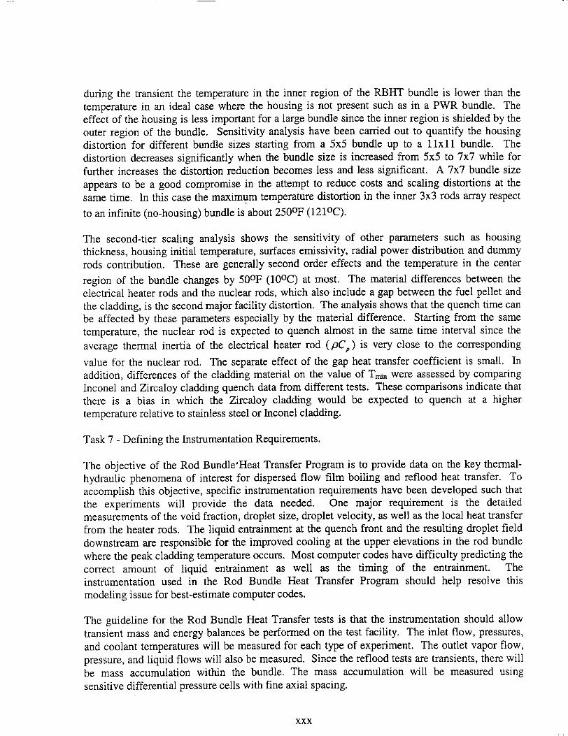
during the transient the temperature in the inner region of the RBHT bundle is lower than the temperature in an ideal case where the housing is not present such as in a PWR bundle. The effect of the housing is less important for a large bundle since the inner region is shielded by the outer region of the bundle. Sensitivity analysis have been carried out to quantify the housing distortion for different bundle sizes starting from a 5x5 bundle up to a 1lxl bundle. The distortion decreases significantly when the bundle size is increased from 5x5 to 7x7 while for further increases the distortion reduction becomes less and less significant. A 7x7 bundle size appears to be a good compromise in the attempt to reduce costs and scaling distortions at the same time. In this case the maximum temperature distortion in the inner 3x3 rods array respect
to an infinite (no-housing) bundle is about 250°F (1210C).
The second-tier scaling analysis shows the sensitivity of other parameters such as housing thickness, housing initial temperature, surfaces emissivity, radial power distribution and dummy rods contribution. These are generally second order effects and the temperature in the center
region of the bundle changes by 50°F (100 C) at most. The material differences between the electrical heater rods and the nuclear rods, which also include a gap between the fuel pellet and the cladding, is the second major facility distortion. The analysis shows that the quench time can be affected by these parameters especially by the material difference. Starting from the same temperature, the nuclear rod is expected to quench almost in the same time interval since the
average thermal inertia of the electrical heater rod (pC,) is very close to the corresponding
value for the nuclear rod. The separate effect of the gap heat transfer coefficient is small. In addition, differences of the cladding material on the value of Tmnn were assessed by comparing Inconel and Zircaloy cladding quench data from different tests. These comparisons indicate that there is a bias in which the Zircaloy cladding would be expected to quench at a higher temperature relative to stainless steel or Inconel cladding.
Task 7 - Defining the Instrumentation Requirements.
The objective of the Rod Bundle'Heat Transfer Program is to provide data on the key thermalhydraulic phenomena of interest for dispersed flow film boiling and reflood heat transfer. To accomplish this objective, specific instrumentation requirements have been developed such that the experiments will provide the data needed. One major requirement is the detailed measurements of the void fraction, droplet size, droplet velocity, as well as the local heat transfer from the heater rods. The liquid entrainment at the quench front and the resulting droplet field downstream are responsible for the improved cooling at the upper elevations in the rod bundle where the peak cladding temperature occurs. Most computer codes have difficulty predicting the correct amount of liquid entrainment as well as the timing of the entrainment. The instrumentation used in the Rod Bundle Heat Transfer Program should help resolve this modeling issue for best-estimate computer codes.
The guideline for the Rod Bundle Heat Transfer tests is that the instrumentation should allow transient mass and energy balances be performed on the test facility. The inlet flow, pressures, and coolant temperatures will be measured for each type of experiment. The outlet vapor flow, pressure, and liquid flows will also be measured. Since the reflood tests are transients, there will be mass accumulation within the bundle. The mass accumulation will be measured using sensitive differential pressure cells with fine axial spacing.
xxx

Using the inlet and exit measurements as well as the measured axial heat flux distribution into the coolant, the actual quality distribution along the bundle, can be obtained above the quench front and the amount of liquid evaporation can be calculated from the data. In a similar fashion, the void distribution along the heated bundle can also be determined to indicate the flow and heat transfer regimes in the bundle and will be used to correlate the measured heat transfer data. The differential pressure drop measurements will have to be corrected for the frictional pressure drop as well as any acceleration pressure drop to infer the local void fraction. Since the actual quality is non-equilibrium, measurements of the true vapor temperature are needed as well as the wall heat flux into the fluid. There will also be ample miniature thermocouples placed into the different subchannels along the axial length of the bundle. In addition, since the spacer grids can promote improved cooling downstream of the spacer, fluid thermocouples will also be placed in these locations. A local quality can be calculated wherever a local vapor temperature exists in the bundle.
The fuel rods will be simulated using electrical heater rods which will have the power capability of simulating the reactor decay power at 20 seconds following reactor scram. These rods will have an internal heating coil with a prescribed axial power shape which is representative of those shapes calculated in Best-Estimate LOCA analyzes. There will be eight thermocouples placed in the rod such that all the rods will fully cover the complete axial length of the bundle. There will be thermocouples at specific elevations to obtain the radial temperature profile in the bundle. The total measured heat flux will be calculated from an inverse conduction calculation using the measured thermocouple data. In addition, these experiments are designed for computer code validation purposes. Therefore, there will be a specific arrangement of the thermocouples and the differential pressure cells within the bundle, such that the heat transfer data can be correlated with the local void fraction.
In addition to the heat transfer behavior and the vapor and structure temperatures, direct data is needed on the flow behavior in the test bundle. In the froth or transition region, data on the local void fraction distribution, interfacial area, droplet/liquid ligament size are lacking. Also in the dispersed flow regime, data are needed on the droplet size, velocity, and number density is also needed for the wall-to-drop radiation heat transfer, and the vapor-to-drop radiation and convective heat transfer. The facility will characterize the flow regime in the froth region where the liquid changes from a continuous liquid flow into a dispersed droplet flow. Therefore, the test section has windows which will permit viewing and photographing the flow at important time periods in the transient.
In addition to the fine axial mesh of the differential pressure cells along the length of the bundle and across the spacer grids for void fraction measurements, a soft gamma ray measuring devise will also be used at selected fixed elevations along the lower portion of the bundle. The gamma densitometer will give chordal average densities of the two-phase flow mixture as the flow regime changes from a dispersed droplet flow to the froth region and finally to solid water. In the Rod Bundle Heat Transfer Program, a pulsed laser technique will be used in conjunction with a fine grid digital camera to obtain drop sizes and droplet velocities. The pulsed laser will provide the backlighting as well as the focus volume for pictures in the center subchannels of the rod bundle. This measurement technique has software which will allow the determination of the
xxxi

droplet spectrum, Sauter mean drop size, droplet velocities, and an estimate of the droplet
number density. These data can be used to calculate the interfacial area of the entrained droplet
phase. The pulsed laser and digital camera technique has not been applied to reflood
experiments before. Therefore, to verify the performance of the system and confirm the
accuracy of the measurements, a series of "bench-top" experiments have been performed with
the new instrumentation and to develop the data reduction and analysis programs to analyze the
droplet data.
With the proposed instrumentation plan, nearly all the highly ranked phenomena will be directly
measured or directly calculated from the experimental data. When a parameter is directly
calculated from the experimental data, the calculation uses the transient mass and energy balance
on the test section to calculate the fluid properties, there is no use of a best-estimate computer
code at this stage of the analysis such that the data analysis is independent of any computer code
which may be validated by the experiments. The use of the various techniques described above
provide a robust instrumentation plan for the Rod Bundle Heat Transfer program.
Task 8 - Developing Facility Input Model.
The COBRA-TF computer code was used to model the RBHT facility. The purpose of this
analysis is to perform pre-test calculations to obtain information about the range of the
parameters to expect during reflood transient. This analysis will also provide basis to develop
the test matrix and will indicate the maximum temperature conditions reached in the bundle for a
given set of conditions.
The COBRA-TF code was developed at the Pacific Northwest Laboratory under the sponsorship
of NRC to provide the best-estimate thermal-hydraulic analyses of LWR vessel during LOCA
accidents. The two-phase flow is described with a two-fluid, three-field model. Thermal
radiation and grid spacer effects are also included in the code as well as a more detailed
dispersed flow film boiling model as given in Section 4 of this report. The code was developed
for use with either rectangular Chrtesian or sub-channel coordinates. Herein the sub-channel
scheme is adopted since it is more suitable for complex and irregular geometries.
Two COBRA-TF models of the RBHT test facility were developed including a two-channel
model and a more detailed individual sub-channel model. The two-channel model is being used
to examine the local fluid conditions within the test facility so as to compare them to those
conditions which are typically predicted in a safety analysis calculations for a plant. This model
does not account for the rod-to-rod or the rod-to-housing radiation heat transfer from the inner
channel which exists in the test bundle. The model does account for the test section housing and
calculates the convection heat transfer to the housing as well as the energy released from the
housing as it quenches.
The two-channel analysis considered a 7x7 rod array comprised of forty-five heater rods, four
unheated rods, and the surrounding housing. The facility modeling approach was to divide the
test facility into four sections and five fluid regions, representing the lower and upper plenums,
the initial unheated length of the rod bundle, the actual heated length of the rod bundle, which
contains two fluid channels. The inner channel and, encompasses a total of sixteen 'hot' rods;
xxxii
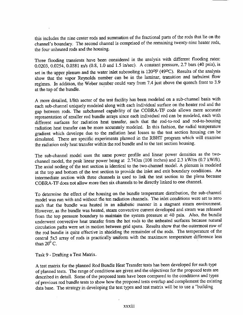
this includes the nine center rods and summation of the fractional parts of the rods that lie on the
channel's boundary. The second channel is comprised of the remaining twenty-nine heater rods,
the four unheated rods and the housing.
Three flooding transients have been considered in the analysis with different flooding rates:
0.0203, 0.0254, 0.0381 mn/s (0.8, 1.0 and 1.5 in/sec). A constant pressure, 2.7 bars (40 psia), is
set in the upper plenum and the water inlet subcooling is 120OF (490C). Results of the analysis
show that the vapor Reynolds number can be in the laminar, transition and turbulent flow
regimes. In addition, the Weber number could vary from 7.4 just above the quench front to 3.9
at the top of the bundle.
A more detailed, 1/8th sector of the test facility has been modeled on a sub-channel basis with
each sub-channel uniquely modeled along with each individual surface on the heater rod and the
gap between rods. The subchannel capability of the COBRA-TF code allows more accurate
representation of smaller rod bundle arrays since each individual rod can be modeled, each with
different surfaces for radiation heat transfer, such that the rod-to-rod and rod-to-housing
radiation heat transfer can be more accurately modeled. In this fashion, the radial temperature
gradient which develops due to the radiation heat losses to the test section housing can be
simulated. There are specific experiments planned in the RBHT program which will examine
the radiation only heat transfer within the rod bundle and to the test section housing.
The sub-channel model uses the same power profile and linear power densities as the two
channel model, the peak linear power being at 2.743m (108 inches) and 2.3 kW/m (0.7 kW/ft).
The axial noding of the test section is identical to the two-channel model. A plenum is modeled
at the top and bottom of the test section to provide the inlet and exit boundary conditions. An
intermediate section with three channels is used to link the test section to the plena because
COBRA-TF does not allow more then six channels to be directly linked to one channel.
To determine the effect of the housing on the bundle temperature distribution, the sub-channel
model was run with and without tfie ten radiation channels. The inlet conditions were set to zero
such that the bundle was heated in an adiabatic manner in a stagnant steam environment.
However, as the bundle was heated, steam convective current developed and steam was released
from the top pressure boundary to maintain the system pressure at 40 psia. Also, the bundle
underwent convective heat transfer from the hot rods to the unheated surfaces because natural
circulation paths were set in motion between grid spans. Results show that the outermost row of
the rod bundle is quite effective in shielding the remainder of the rods. The temperature of the
central 5x5 array of rods is practically uniform with the maximum temperature difference less
than 200 C.
Task 9 - Drafting a Test Matrix.
A test matrix for the planned Rod Bundle Heat Transfer tests has been developed for each type
of planned tests. The range of conditions are given and the objectives for the proposed tests are
described in detail. Some of the proposed tests have been compared to the conditions and types
of previous rod bundle tests to show how the proposed tests overlap and complement the existing
data base. The strategy in developing the test types and test matrix will be to use a "building
xxxiii
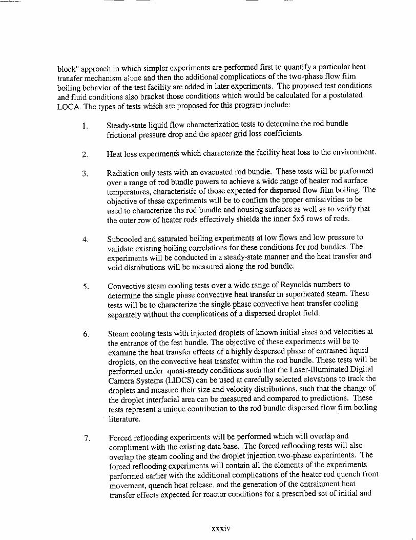
block" approach in which simpler experiments are performed first to quantify a particular heat
transfer mechanism alone and then the additional complications of the two-phase flow film
boiling behavior of the test facility are added in later experiments. The proposed test conditions
and fluid conditions also bracket those conditions which would be calculated for a postulated
LOCA. The types of tests which are proposed for this program include:
1. Steady-state liquid flow characterization tests to determine the rod bundle
frictional pressure drop and the spacer grid loss coefficients.
2. Heat loss experiments which characterize the facility heat loss to the environment.
3. Radiation only tests with an evacuated rod bundle. These tests will be performed
over a range of rod bundle powers to achieve a wide range of heater rod surface
temperatures, characteristic of those expected for dispersed flow film boiling. The
objective of these experiments will be to confirm the proper emissivities to be
used to characterize the rod bundle and housing surfaces as well as to verify that
the outer row of heater rods effectively shields the inner 5x5 rows of rods.
4. Subcooled and saturated boiling experiments at low flows and low pressure to
validate existing boiling correlations for these conditions for rod bundles. The
experiments will be conducted in a steady-state manner and the heat transfer and
void distributions will be measured along the rod bundle.
5. Convective steam cooling tests over a wide range of Reynolds numbers to
determine the single phase convective heat transfer in superheated steam. These
tests will be to characterize the single phase convective heat transfer cooling
separately without the complications of a dispersed droplet field.
6. Steam cooling tests with injected droplets of known initial sizes and velocities at
the entrance of the Cest bundle. The objective of these experiments will be to
examine the heat transfer effects of a highly dispersed phase of entrained liquid
droplets, on the convective heat transfer within the rod bundle. These tests will be
performed under quasi-steady conditions such that the Laser-Illuminated Digital
Camera Systems (LIDCS) can be used at carefully selected elevations to track the
droplets and measure their size and velocity distributions, such that the change of
the droplet interfacial area can be measured and compared to predictions. These
tests represent a unique contribution to the rod bundle dispersed flow film boiling literature.
7. Forced reflooding experiments will be performed which will overlap and
compliment with the existing data base. The forced reflooding tests will also
overlap the steam cooling and the droplet injection two-phase experiments. The
forced reflooding experiments will contain all the elements of the experiments
performed earlier with the additional complications of the heater rod quench front
movement, quench heat release, and the generation of the entrainment heat
transfer effects expected for reactor conditions for a prescribed set of initial and
xxxiv

boundary conditions. The focus of these experiments is to examine the generation of the entrainment at the quench front and within the transition region.
8. Simple gravity reflood experiments or variable inlet injection experiments will also be performed. These experiments will examine the system response on the inlet flooding rate into the test bundle and the resulting heat transfer within the bundle.
The ranges of conditions for the experiments will cover the current ranges of conditions which
best-estimate and Appendix K reflood models are required to calculate. The precise test conditions are not given since there is a need to perform pre-test predictions so as to select the range of rod powers and initial temperatures to provide the data needed while at the same time,
to minimize the duty on the heater rods. However, the facility design envelope is sufficiently
broad such that the tests can be performed over a wide range of initial and boundary conditions.
Rather than the usual approach of marching blindly through a pre-determined matrix to meet the program's milestones, the test matrix for the RBHT program will remain flexible so that it can be
responsive to model development needs. Although the proposed test matrix is somewhat nonspecific, the various types of tests have been carefully structured. These include a well-defined progression from bundle characterization (pressure drop and heat loss experiments) to radiationonly tests, single-phase heat transfer tests, quasi-steady dispersed flow heat transfer tests (i.e., droplet injection tests), to forced reflood and gravity reflood tests. It is decided that flexibility in
the test matrix be maintained so that as the model development progresses and needs are better
identified, the matrix can be adjusted accordingly to make the program most cost effective.
Task 10 - Test Facility Design.
The Rod Bundle Heat Transfer (RBHT) test facility is designed to conduct systematic separateeffects tests under well-controlled laboratory conditions in order to generate fundamental rod bundle heat transfer data includinj single phase steam cooling tests, low flow boiling tests, steam
flow tests with injected droplets and inverted annular film boiling and dispersed flow film boiling heat transfer in rod bundles. The facility is capable of operating in both forced and variable reflood modes covering wide ranges of flow and heat transfer conditions at pressures from 20 psig to 60 psig (2.33 bars to 5.01 bars).
The test facility consists of five major components. These are:
1. test section consisting of a lower plenum, a low-mass flow housing containing the heater rod bundle, and an upper plenum,
2. coolant injection and steam injection systems, 3. phase separation and liquid collection systems, 4. downcomer and crossover leg system, and 5. system pressure oscillation damping tank and steam exhaust piping.
All components are well insulated to minimize heat losses to the environment, and to minimize errors in the overall heat balances calculations around the system.
xxxv
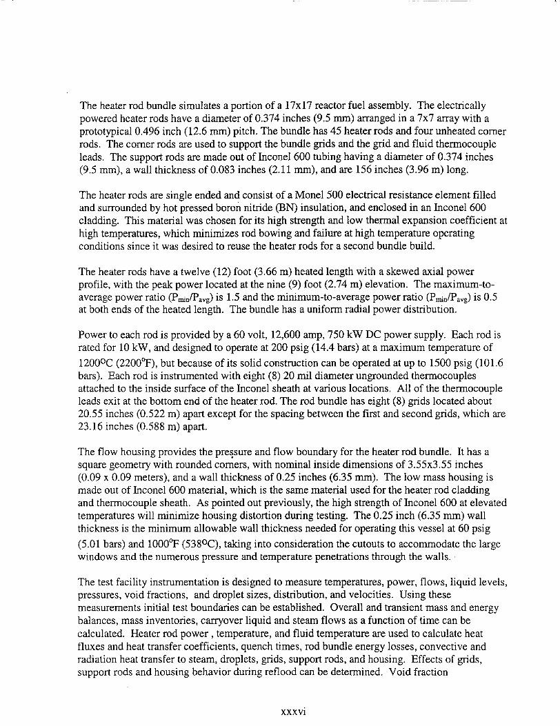
The heater rod bundle simulates a portion of a 17x17 reactor fuel assembly. The electrically powered heater rods have a diameter of 0.374 inches (9.5 mm) arranged in a 7x7 array with a prototypical 0.496 inch (12.6 mm) pitch. The bundle has 45 heater rods and four unheated corner rods. The corner rods are used to support the bundle grids and the grid and fluid thermocouple leads. The support rods are made out of Inconel 600 tubing having a diameter of 0.374 inches (9.5 umm), a wall thickness of 0.083 inches (2.11 mm), and are 156 inches (3.96 m) long.
The heater rods are single ended and consist of a Monel 500 electrical resistance element filled and surrounded by hot pressed boron nitride (BN) insulation, and enclosed in an Inconel 600 cladding. This material was chosen for its high strength and low thermal expansion coefficient at high temperatures, which minimizes rod bowing and failure at high temperature operating conditions since it was desired to reuse the heater rods for a second bundle build.
The heater rods have a twelve (12) foot (3.66 m) heated length with a skewed axial power profile, with the peak power located at the nine (9) foot (2.74 m) elevation. The maximum-toaverage power ratio (Pmin/Pavg) is 1.5 and the minimum-to-average power ratio (Pminn/Pavg) is 0.5 at both ends of the heated length. The bundle has a uniform radial power distribution.
Power to each rod is provided by a 60 volt, 12,600 amp, 750 kW DC power supply. Each rod is rated for 10 kW, and designed to operate at 200 psig (14.4 bars) at a maximum temperature of
12000C (2200°F), but because of its solid construction can be operated at up to 1500 psig (101.6 bars). Each rod is instrumented with eight (8) 20 mil diameter ungrounded thermocouples attached to the inside surface of the Inconel sheath at various locations. All of the thermocouple leads exit at the bottom end of the heater rod. The rod bundle has eight (8) grids located about 20.55 inches (0.522 m) apart except for the spacing between the first and second grids, which are 23.16 inches (0.588 m) apart.
The flow housing provides the pressure and flow boundary for the heater rod bundle. It has a square geometry with rounded corners, with nominal inside dimensions of 3.55x3.55 inches (0.09 x 0.09 meters), and a wall thickness of 0.25 inches (6.35 mm). The low mass housing is made out of Inconel 600 material, which is the same material used for the heater rod cladding and thermocouple sheath. As pointed out previously, the high strength of Inconel 600 at elevated temperatures will minimize housing distortion during testing. The 0.25 inch (6.35 mm) wall thickness is the minimum allowable wall thickness needed for operating this vessel at 60 psig (5.01 bars) and 1000°F (5380C), taking into consideration the cutouts to accommodate the large windows and the numerous pressure and temperature penetrations through the walls.
The test facility instrumentation is designed to measure temperatures, power, flows, liquid levels, pressures, void fractions, and droplet sizes, distribution, and velocities. Using these measurements initial test boundaries can be established. Overall and transient mass and energy balances, mass inventories, carryover liquid and steam flows as a function of time can be calculated. Heater rod power, temperature, and fluid temperature are used to calculate heat fluxes and heat transfer coefficients, quench times, rod bundle energy losses, convective and radiation heat transfer to steam, droplets, grids, support rods, and housing. Effects of grids, support rods and housing behavior during reflood can be determined. Void fraction
xxxvi
measurements below the quench front and in the froth level above the quench front, in
conjunction with the laser illuminated digital camera measurements are used to determine droplet
entrainment behavior droplet effects on heat transfer, and steam desuperheating. The laser
illuminated digital camera system measurements provide droplet size distribution and velocities
during reflood.
Loop instrumentation has sixty-one (61) instrumentation channels which are assigned to the
measurement of electrical power, fluid and wall temperatures, levels, flows, differential
pressures, and static pressure. The injection water supply tank has three fluid and three wall
thermocouples to monitor water and wall temperatures during heat-up prior to testing. It has a
differential pressure transmitter used as a level meter to determine water mass in the tank and
mass depletion during reflood testing. It also has a static pressure transmitter which monitors the
nitrogen overpressure and controls the nitrogen flow needed to maintain a constant pressure
during forced injection reflood tests.
The Data Acquisition System consists of a digital computer and several analog conversion
subsystems. It uses a Ziatech ZT-8910 digital processor capable of collecting, storing, and
retrieving data from power, pressure, temperature, level and flow instrumentation. It can also
provide control functions, and display critical operating parameters during testing. It is to be
designed to process up to 412 instrumentation channels at a maximum sampling rate of 10 Hz.
This system, in conjunction with panel mounted strip chart recorders, gauges, and controllers, is
used to establish test boundary conditions prior to starting a test.
In summary, the RBHT is designed as a flexible rod bundle separate-effects test facility which
can be used to perform single-phase and two-phase experiments under well-controlled laboratory
conditions to generate fundamental reflood heat transfer data. The facility is capable of
operating in both forced and variable reflood modes covering wide ranges of flow and heat
transfer conditions at pressures up to 60 psig (5.01 bars). It has extensive instrumentation that
meets all the instrumentation requirements developed under Task 7. It can be used to conduct all
types of the planned experiments according to the test matrix developed under Task 9. The
present design also allows future upgrading of the facility for the performance of high-pressure
transient film boiling tests. It is felt that the RBHT facility with its robust instrumentation
represents a unique NRC facility for the in-depth studies of the highly ranked reflood phenomena
identified in the PIRT table developed under Task 1.
Concluding Remarks.
The Rod Bundle Heat Transfer Program will be of considerable benefit to the NRC effort to
improve the TRAC reflood model. The effort will of necessity include not only wall-to-fluid
heat transfer correlations but also models for interfacial shear and interfacial heat transfer. To
develop and assess models for these phenomena with the goal of significantly improved accuracy
(to provide a better estimate of margin) and to minimize the potential for compensating errors
will require a database that includes more detailed information than is currently available. In
addition, this detailed data base needs to be for prototypic rod bundle geometry as large
differences exist between the data obtained from heated tubes and rod bundles. It is exactly this
data deficiency for which the Rod Bundle Heat Transfer program is designed. The successful
xxxvii

completion of this experimental program will make a fundamental contribution to the database
for reflood model development and is a key component of the NRC's code improvement
program.
Specifically, the Rod Bundle Heat Transfer program will generate detailed data for model
development that are either unique or of higher quality than currently available data in the
following areas:
" Two-Phase Convective Enhancement: In dispersed flow film boiling, the primary heat
transfer mechanism is convective heat transfer to superheated steam. It is known that the
steam heat transfer coefficient can be enhanced by up to 100% due to the presence of
entrained droplets. No suitable models currently exist for this phenomenon. The
combination of single-phase vapor heat transfer tests with the forced droplet injection tests
(where drop size and flow rate are known) will result in the development of the much needed
model.
" "Inverted Annular" Film Boiling: The liquid rich region just downstream of the quench front
(void fraction of 20% to 60%) provides the precursory cooling that controls the quench front
velocity and provides the source of vapor and entrained liquid for the dispersed flow film
boiling region. It has been demonstrated that many of the apparent functional dependencies
(i.e., mass flux, subcooling, and distance from the quench front) for this heat transfer regime
are primarily due to the axial profile of the void fraction in this region. Currently available
data for this regime in rod bundles is insufficient for model development due to the coarse
spacing (from one to two feet) used for the delta-P cells to measure the void fraction. The
RBHT program will redress this data deficiency through the use of finely spaced delta-P cells
(three inches apart over a distance of two feet) and by a local void fraction measurement
provided by a low energy gamma-densitometer.
" Dispersed Flow Film Boiling:. Once the uncertainty involving convective enhancement is
resolved, there still remains the difficulty in calculating the heat transfer rate for this regime
due to the difficulty in calculating the steam superheat. The amount of steam superheat is
governed by the interfacial heat transfer between the steam and the evaporating drops. To
correctly calculate the interfacial heat transfer requires the knowledge of both the entrained
droplet flow rate and diameter. There is very little data of this type currently available for
quenching rod bundles. The RBHT program will generate the needed database through the
use of advanced instrumentation, specifically through the use of the Laser Illuminated Digital
Camera System (LIDCS).
This program will also augment the database needed for model development in the areas of grid
spacer effects in dispersed flow film boiling, transition boiling heat transfer during reflood, and
for interfacial heat transfer and shear in rod bundles at low pressure. These reasons justify the
need for developing the Rod Bundle Heat Transfer Facility and for conducting separate-effects
tests in this facility to obtain new and unique data for model development and code validation at
the most fundamental subcomponent levels. The RBHT program will complement NRC's efforts
in improving the TRAC reflood models.
xxxviii

Acknowledgments
There were several individuals who made significant contributions to this report which the authors would like to acknowledge. The technical efforts of Ernest Miklavic, Andrew Ireland, Christina D'Arrigo and James Apple are gratefully acknowledged. The editing, correcting, and typing efforts of Mrs. Christine Wilson and Kristie Kalvin are also gratefully acknowledged and without their effort this report would not have been completed as scheduled. The technical comments and insights by the two independent Nuclear Regulatory Commission sponsored peer review panels for the program objectives and approach, and for the instrumentation design are also gratefully acknowledged. The authors also acknowledge the guidance, review, and active participation that Mr. David Bessette and Joseph Kelly of the Nuclear Regulatory Commission have played in the Rod Bundle Heat Transfer Program. The comments which were received were integrated into the test design and analysis and will improve the quality of the work performed in the program.
We also acknowledge the continuing support of Dr. Benson, Head of the Mechanical and Nuclear Engineering Department. The Rod Bundle Heat Transfer Program is a cost shared program between The Pennsylvania State University and the Nuclear Regulatory Commission. The authors acknowledge the financial support provided by the University for the equipment match and the new building annex for the test facility. In particular, the authors acknowledge the support of Drs. D.N.Wormley, L. C. Burton, L. R. Hettche, and R. A. Erickson. The experiments will be performed at the Thermal Propulsion Research Facility (Test Site) of Applied Research Laboratory, Penn State. The authors acknowledge the continuing support and help of Dr. D. H. Kiely, R. A. Grove, I. S. McClellan, R. A. Peters, C. P. Jones, D. M. Adams, and J. R. Bischof from the Applied Research Laboratory.
xl
1. INTRODUCTION
1.1 Background
Safety analysis is performed on Nuclear Reactor power plants to ensure the health and safety of the public, for accidents which are postulated to occur. Accidents are analyzed which are anticipated to occur over the life time &of the plant as well as hypothetical accidents which are not expected to occur but are postulated to determine the mitigating features of the particular reactor design. Each reactor design has Engineered Safeguard Systems which are safety systems designed to mitigate accident scenarios.
Within the reactor design basis, the most challenging accident which is examined is a large-break Loss Of Coolant Accident (LOCA). Analysis of this particular accident can result in limits in the reactor total core power as well as the allowable peak linear fuel rod power in the hottest rods. For this type of accident, the initial coolant in the reactor core is expelled out the broken piping and the core cooling is dependent on the Engineered Safeguards Systems. Analysis of the particular accident verifies that the design of the Engineered Safeguards Systems will mitigate the accident. In a large-break LOCA, the fuel rod cladding is calculated to rupture at high temperatures, and the primary piping is assumed to have failed so as to generate the LOCA. Without adequate core cooling the reactor core will continue to overheat and can lead to failure thereby releasing fission products from the fuel.
The Nuclear Regulatory Commission developed the Appendix K requirements in 1973 for acceptable analytical methods used to predict the safety performance of the Engineered Safeguards System for reactor designs. The requirements were acknowledged to be conservative to account for the uncertainties in the calculation and the database at that time. A significant research effort was performed by the NRC, Electrical Power Research Institute (EPRI), and the reactor vendors from 1973 to 1988 to determine the degree of conservatism in the Appendix K requirements. During the same time period, the American Physical Society urged the NRC to develop improved, more realistic "Best-Estimate" analytical computer models for the reactor systems such that realistic calculations could be performed. In 1988, the Appendix K rule was revised and Best-Estimate thermal-hydraulic methods were allowed to be used to evaluate the reactor system and the Engineering Safeguards System response to a postulated LOCA.
With the approval of the Appendix K rule revisions, vendors are starting to utilize "BestEstimate" safety analysis thermal-hydraulic methods to perform large-break LOCA analysis to evaluate the allowable core thermal limits. Even with the application of best-estimate methods, the large-break LOCA still is generally the most limiting transient and results in establishing the maximum allowable fuel rod linear power level (kW/ft). Typically what has occurred is that as Best-Estimate analysis methods have identified peak linear heat rate margin; this margin has been used by the utility or the vendor for power up- ratings, longer fuel cycles, low leakage core loadings and advanced fuel designs to improve the economics of the nuclear power plant. All of these economic improvements result in the need for higher operating linear heat generation rates.
1-1
This is true for both BWR and PWR designs. When the best-estimate methods are applied with the higher linear heat rates, the resulting calculated peak cladding temperatures are nearly the same as those previously calculated using the original Appendix K requirements. However, the difference is that the allowable linear heat rate, (kW/ft) is now higher.
The best-estimate calculations indicate that for nearly all PWR designs the peak cladding temperatures are reached during the reflood portion of the transient at low pressures, typically one to three bars. A similar situation also occurs in the hot channel for the more modem BWR designs (BWR5 and 6), as well. The flow pattern in the BWR hot channel is co-current up flow during reflood similar to a PWR.
There are two basic flow regimes for reflooding in a rod bundle. For high flooding rates, typically, 6-inches/sec (0.15 m/sec), the dominant flow regime for the post-CHIF regions in the bundle is an inverted annular regime in which a thin layer of vapor separates the heated wall from the sub cooled liquid flow which nearly fills the channel. Since the inlet flow is larger then the quench rate of the fuel rods, a long region of inverted film boiling can exist above the quench front. As one proceeds upward along the bundle, the liquid becomes saturated and begins to break into chunks or liquid slugs. The length of the inverted annular and the liquid chunk regimes depends on the flooding rate into the heated bundle, the initial sub cooling of the liquid, the system pressure, and the rod bundle initial temperature and power level. The heat transfer in this regime is very high and results in immediate clad temperature turnover such that lower peak cladding temperatures are calculated for this reflood regime. Figure 1-1 shows an example of the high flooding rate reflood heat transfer and flow regime.
For low flooding rates, there is no sub cooled inverted annular film boiling region. Because of the low injection flow rate, the liquid quickly reaches saturation and there is bulk boiling of the fluid below the quench front. In the quench front region, and above the quench front, there is a froth region which has a void fraction which transitions between a low void fraction, below the quench front, to the much higher void fraction in the dispersed flow regions above the quench front. This behavior is shown in Figure 1-2. The dominant flow regime for the low flooding rates is a highly dispersed flow film-boiling region in which the heat transfer rates are very low. The heat transfer in this region occurs between the heated wall and the superheated steam. The liquid droplets in the superheated steam evaporate reducing the steam temperature as well as increasing the flow rate of the steam. As a result, the calculated peak cladding temperature usually occurs in this region. In most reactor reflood calculations, after the initial surge into the core, the flooding rates are very low, typically 1-inch/sec (0.0254 mrsec) or less such that the dispersed flow film boiling region is the dominant flow regime of interest and is the heat transfer regime in which the peak cladding temperature occurs.
In either case and for all designs, the thermal-hydraulic heat transfer phenomena which dominates the reflood portion of the transient is dispersed flow film boiling. The heat transfer rates during this period are very low and several different mechanisms are responsible for the total wall heat flux. No single mechanism dominates the heat transfer process such that several
1-2
different mechanisms must be predicted by the best-estimate calculational tool with roughly equal precession. Those mechanisms include:
Convection to superheated vapor, Surface radiation to vapor and droplets, Interfacial heat transfer between droplets and superheated vapor, Direct contact heat transfer between the wall and entrained liquid, Convective enhancement of the vapor by the entrained droplets Impact of structures (grids) in the rod bundle causing flow acceleration and droplet break-up, Quench fronts at the top and bottoms of the rods,
Also, since the different mechanisms are of comparable magnitude, improving one particular model is difficult since very little data is available to isolate its particular contribution to the total wall heat flux. Therefore, compensating errors can result as the code's predictive capabilities are improved.
Dispersed flow film boiling also dominates the down flow period of the PWR blow down transient as well as the reflood transient. Similar heat transfer mechanisms are present for the blow down flow period as well as the reflood period. The primary difference is that the vapor convection term is more dominate for the blow down situation as compared to the reflood phase, and the vapor has less superheat.
The single largest uncertainty in predicting the dispersed flow film boiling heat transfer in reflooding rod bundles is the liquid entrainment at the top of the froth region just above the quench front. The froth region is a region at and above the quench front in which the void fraction changes from low values typical of the boiling below the quench front, to the very high values in the dispersed flow film-boiling regime. The froth regime is a liquid rich regime while the dispersed flow regime is very liquid deficient. Figure 1-3 shows the quench front data from a low flooding rate FLECHT-SEASET test(''1 with the froth region location indicated. Figurel-4 indicates a schematic of the flow regime just above the quench front within the froth region of
the flow. In this region, the steam generation from the quenching of the fuel rods results in very large vapor velocities which entrain and shear liquid filaments into droplets which are then swept into the upper regions of the rod bundle. The entrained droplets provide cooling by several different mechanisms in the upper regions of the rod bundle where the resulting peak clad temperatures are calculated.
1-3
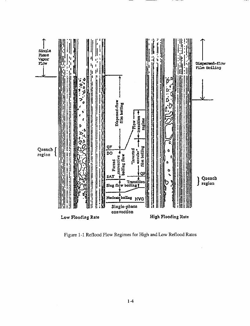
Va~or ii.fi
.111 6*~o~
Quench !ih li QF] b region r.I~~
I ~SAT . Il0 :1 bu IiOfiy
con vection
Low FloodinZ RaZte High Flooding Rate
Figure 1-1 Reflood Flow Regimes for High and Low Reflood Rates
&iSparmd-fthw
1-4
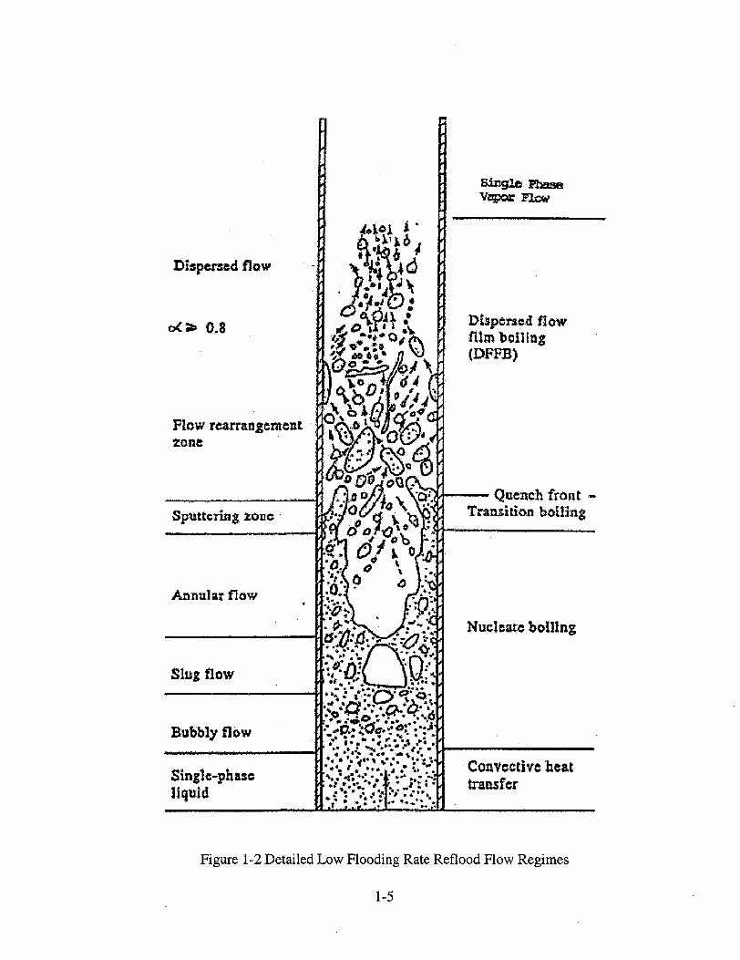
Dispersed flow
o•0.8
Flow rearrangement zone.
Annular flow
Single PtnM Vqz~r flogW
Dispcncd flow film boiling (DFFB)
front -
Nuceate boiling
Figure 1-2 Detailed Low Flooding Rate Reflood Flow Regimes
1-5
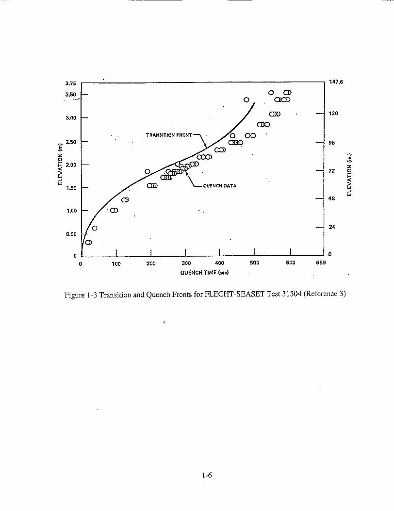
3.75
3.50 0 CD - 0 cO
3.00 -- Cm 120
TRANSITION FRONT 0 00 .. 2.50 -- Q• 96
z 0 S2.00 Z >E0 72 0
-..
UJ - 48
1.00o CD •
24
0.50 ,C]
I I I0
0 100 200 300 400 500 600 689
QUENCH TIME (sac)
Figure 1-3 Transition and Quench Fronts for FLECHT-SEASET Test 31504 (Reference 3)
1-6
•1 ji ,,,,11 •
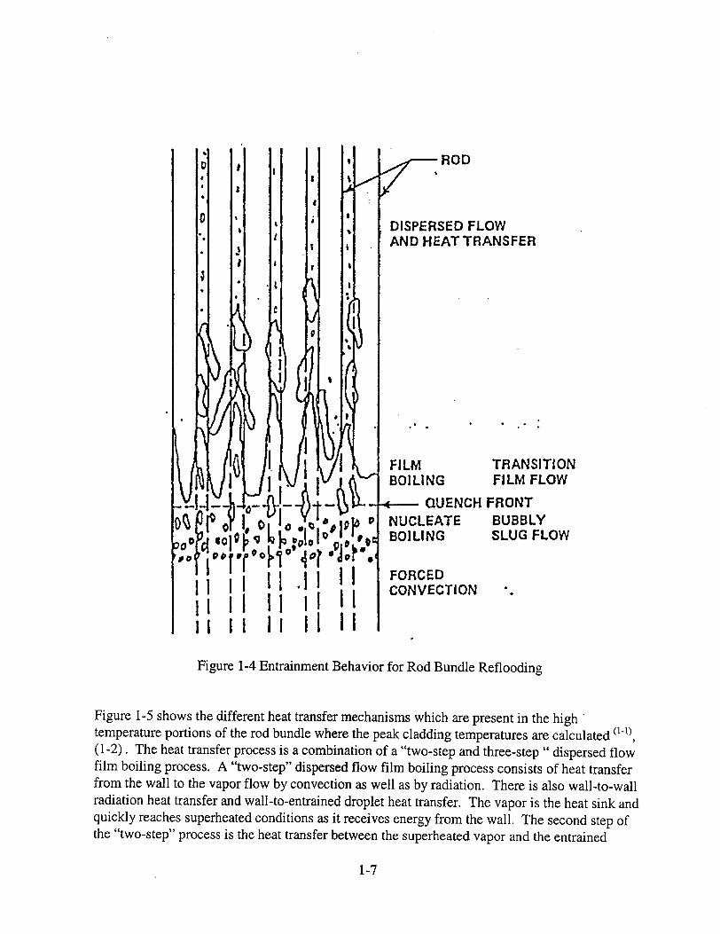
ROD
DISPERSED FLOW AND HEAT TRANSFER
FILM BOILING
4- QUENCH NUCLEATE BOILING
TRANSITION FILM FLOW
FRONT BUBBLY SLUG FLOW
II: I1 .1 H! FORCED il ,~ ii !1 l CONVECTION
Ii i I I!I
Figure 1-4 Entrainment Behavior for Rod Bundle Reflooding
Figure 1-5 shows the different heat transfer mechanisms which are present in the high temperature portions of the rod bundle where the peak cladding temperatures are calculated (11)
(1-2). The heat transfer process is a combination of a "two-step and three-step "dispersed flow film boiling process. A "two-step" dispersed flow film boiling process consists of heat transfer from the wall to the vapor flow by convection as well as by radiation. There is also wall-to-wall radiation heat transfer and wall-to-entrained droplet heat transfer. The vapor is the heat sink and quickly reaches superheated conditions as it receives energy from the wall. The second step of the "two-step" process is the heat transfer between the superheated vapor and the entrained
1-7

droplets. The interfacial heat transfer between the drops and the vapor lowers the vapor temperature which is the fluid heat sink for the wall heat transfer. The "two-step" film boiling process becomes a "three-step" process as the wall temperature decreases such that there can be intermittent direct ( or near direct) droplet-wall contact heat transfer. It is believed that the direct wall contact heat transfer component occurs within and just above the froth region which results in improved heat transfer. The improved heat transfer in this region can be seen from the FLECHT-SEASET test data.
The ability of a best-estimate computer code to accurately predict the integrated effects of the individual phenomena for the dispersed flow film-boiling region is a challenge. The uncertainty in the individual models is large and the integrated effects of the uncertainties will accumulate as the calculation progresses upward along the heated channel. The error or uncertainty accumulation is one reason that the code predictions of temperatures above the mid-plane of the FLECHT-SEASET rod bundle or the Japanese Cylindrical Core Test Facility have always been worse than predictions lower in the bundle, closer to the froth region. Also, code calculations for lower flooding rates which are reflected in a slower quench front velocity and a longer transient time; show poorer predictions relative to the test data.
1-8

Wall
(i) Wall-to-vapour convection
S- (5) Wall-to-vapour radiation
(2) Vapour-to-drop convection / • oe . •
f," (7) Vapour generation a .:.°
q4L U\... * *****.*. ...
(4) Wall-to-drop radiation
9;L
(6) Vapour-to-drop radiation
/
(3) Wall-to-drop direct contact * heat Iransaer
Figure 1-5 Heat and Mass Transfer Mechanism in Dispersed Flow Film Boiling (from Reference) (1-2)
1-9

1.2 Program Objectives
Reflood Heat Transfer experiments have been performed since the original Full Length Emergency Core Heat Transfer ( FLECHT) program began in 1967. These experiments were designed to examine the total heat transfer for a heated rod bundle subjected to reflood bottom or top spray effects. At this time no data existed for rod bundles in the literature, therefore, the initial tests were more scoping and were designed to provide data on the overall heat transfer rather than the phenomena which were responsible for the heat transfer. The initial FLECHT tests were more sparsely instrumented and one could not perform a mass balance on the tests.
The test conditions in the original FLECHT series did not reflect the effects of steam binding and
hence the flooding rates are much larger than current plants. The rod peak powers were also higher. Other FLECHT test series were also performed in which the flooding rates were reduced
to better cover the plant calculated conditions, however, the objective remained the same, to determine the total heat transfer over a wider range of conditions. A very highly empirical heat transfer correlation was developed, which was a function of the reactor system parameters (not local thermal-hydraulic conditions) and was used in the Appendix K models by the vendors and the NRC. Because the heat transfer correlation was empirical and not based on any physical model, the application for different rod bundle arrays, conditions, axial power shapes, and geometries was suspect.
Improved reflood experiments were performed in the FLECHT-SEASET program which was initiated in the mid 1970's. The FLECHT-SEASET tests represent the first attempt to understand the reflood phenomena. Additional instrumentation was added to examine the thermal-hydraulic conditions within the test bundle. However, the tests were conducted in the same manner as the
previous FLECHT tests and the primary result of these tests was the overall reflood heat transfer
for a different rod bundle array which was correlated in a similar manner as the previous FLECHT experiments. There was additional analysis performed on the FLECHT-SEASET tests to attempt to divide the measured total heat transfer into the individual heat transfer components, however, the uncertainties were very large such that the phenomena could be identified but not
quantified with sufficient confidence. The ACHILLES and PERICLES experiments were similar
to the FLECHT-SEASET tests in size and types of test performed. Both of these test series used
prototypical spacer grids, which were found to enhance heat transfer. However, no local data was obtained to explain the reflood heat transfer phenomena.
There were also systems reflood tests such as the FLECHT-SET tests, the 2D/3D program
Cylindrical Core Test Facility (CCTF), the Slab Core Test Facility (SCTF); and the KWU 340 rod systems tests. These experiments primarily examined the effects of the reactor system effects
on the core reflooding rate and the resulting heat transfer within the core. No attempts were
made to instrument these experiments to determine the local heat transfer phenomena within the
rod bundle, rather, the determination of the system response during reflood was the test objective.
The overall heat transfer in the rod bundle was measured as well as the heater rod temperatures.
1-10

All of these experiments made important contributions to the total understanding of the reflood process for a PWR or a BWR and the data is useful, in varying degrees, for safety analysis computer code validation. However, none of these experiments were designed with the objective of model development and validation based on the local thermal-hydraulic conditions. The experiments which have been conducted were primarily to provide data over a wide range of system conditions for an Appendix K reactor safety analysis and not to examine the details of the local two-phase flow and heat transfer effects which could occur in a rod bundle during reflooding. Therefore, when this data is used for computer code validation and the predictions do not agree with the data, the analyst does not have sufficient experimental information to determine which of the many models is causing the mis-prediction. As a result, as models are "improved", compensating errors can enter into the calculations which tend to make the computer code suspect when extrapolating the results to the full scale PWR or BWR.
One important feature of the Rod Bundle Heat transfer program is that the experiments and the instrumentation are designed from a model development and validation point of view, rather than an Appendix K margin approach. Much of the instrumentation will be unique and will be used to determine local conditions. The data can be used to validate specific models in a manner such that the effects of compensating error can be identified and corrected. The program will also break the dispersed flow film boiling phenomena into its individual contributions such as:
Single phase pressure drop experiments to characterize the spacer grids and the rod bundle,
Surface-to-surface, surface to liquid, and surface to vapor radiation heat transfer,
Convection of superheated steam over a wide range of Reynolds numbers,
The effects of entrained droplets within a superheated steam flow, and the effects of the droplets on convection enhancement, as well as evaporation,
Forced reflood tests which will cover a wide range of reflood flow regimes and heat transfer state
Variable reflood tests in which the interaction of the injected flow and the quench front can be assessed.
The instrumentation is designed to provide data on the local void fraction within the froth regions, the steam superheating that occurs along the bundle, the liquid entrainment within the bundle, entrained drop sizes, distributions, velocities and droplet velocity distributions.
The Rod Bundle Heat Transfer Program is needed to provide detailed data which can be used to improve the NRC's safety analysis prediction capabilities for the large break LOCA transient.
1-11
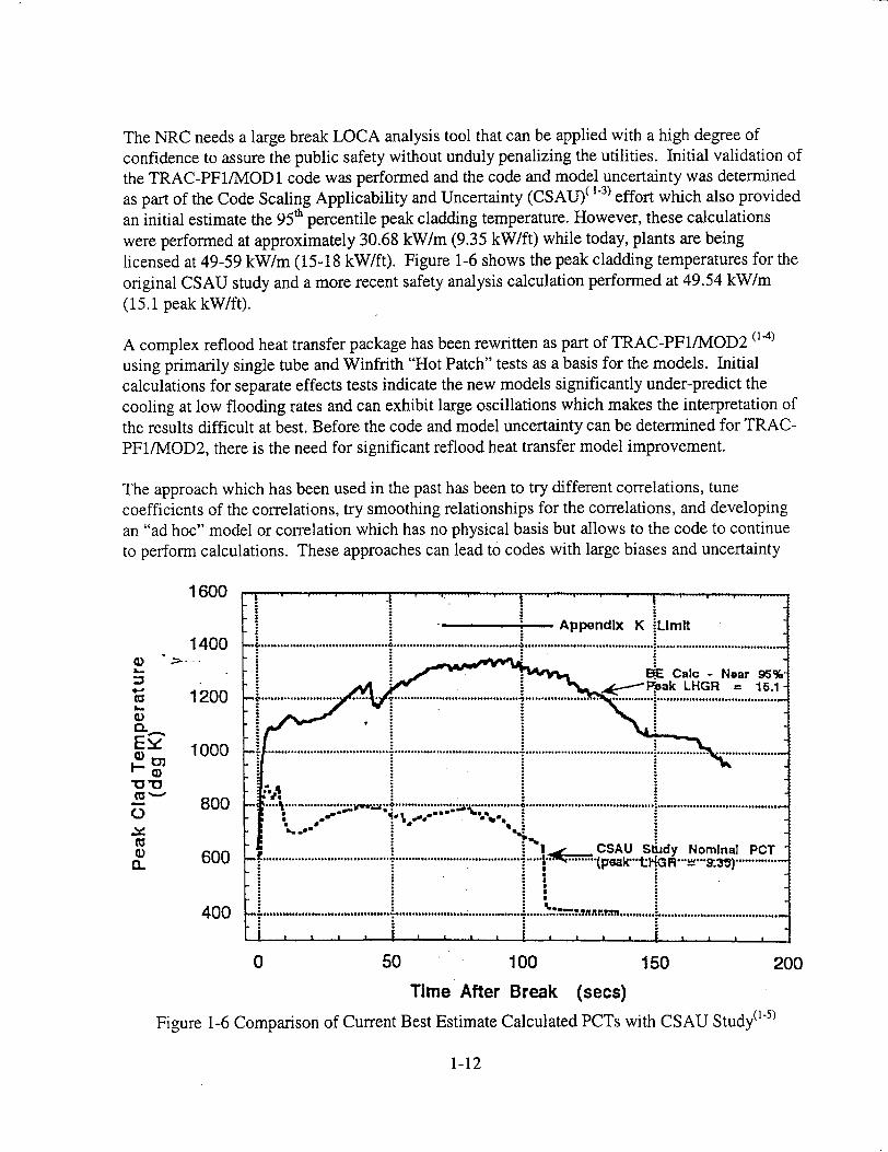
The NRC needs a large break LOCA analysis tool that can be applied with a high degree of confidence to assure the public safety without unduly penalizing the utilities. Initial validation of the TRAC-PF1/MOD1 code was performed and the code and model uncertainty was determined as part of the Code Scaling Applicability and Uncertainty (CSAU)( 1-3) effort which also provided an initial estimate the 95t percentile peak cladding temperature. However, these calculations were performed at approximately 30.68 kW/m (9.35 kW/ft) while today, plants are being licensed at 49-59 kW/m (15-18 kW/ft). Figure 1-6 shows the peak cladding temperatures for the original CSAU study and a more recent safety analysis calculation performed at 49.54 kW/m (15.1 peak kW/ft).
A complex reflood heat transfer package has been rewritten as part of TRAC-PF1/MOD2 (1-4)
using primarily single tube and Winfrith "Hot Patch" tests as a basis for the models. Initial calculations for separate effects tests indicate the new models significantly under-predict the cooling at low flooding rates and can exhibit large oscillations which makes the interpretation of the results difficult at best. Before the code and model uncertainty can be determined for TRACPF1/MOD2, there is the need for significant reflood heat transfer model improvement.
The approach which has been used in the past has been to try different correlations, tune coefficients of the correlations, try smoothing relationships for the correlations, and developing an "ad hoc" model or correlation which has no physical basis but allows to the code to continue to perform calculations. These approaches can lead to codes with large biases and uncertainty
CD
"0)"
a) 0~ Z5.
1600
1400
1200
1000
800
600
400
Appendix K iLImlt
6E Cabc - Near 95% : ....-- Fak LHGR 15.1
I CSAU Sljdy Nominal PCT S .............. ............ ..... . ...... .. A .............
. . .. .. ..... ... ,.... -. .. . ............. .... .. ,.......... , .. ........... pna m ,........ ....... ,..........................
0 50 100 150 200
Time After Break (secs)
Figure 1-6 Comparison of Current Best Estimate Calculated PCTs with CSAU Study(15)
1-12

when compared to a comprehensive data set. Also, adjusting coefficients on correlations to match data can result in compensating errors which may not scale properly from the test configuration to the full size reactor.
The Rod Bundle Heat Transfer Program is designed to provide detailed data on local conditions which can be used for model development. Models will be developed and selected based on fundamental assessments such that the correct heat transfer is predicted for the given local fluid conditions. The tests in the Rod Bundle Heat Transfer Program are structured so as to decompose the complex nature of dispersed flow film boiling into the component models that a computer code would calculate. In this fashion, compensating errors in the models will be reduced. The result will be a more accurate analysis tool for the NRC for best-estimate audit calculations.
1.3 Products from the Rod Bundle Heat Transfer Program
The detailed experimental data and the associated model development will provide the NRC with an improved analytical capability to be applied for Risk Informed Regulation for the large break LOCA. Improved models will reduce the code uncertainty which must be assessed as part of the best-estimate methodology using CSAU. The resulting analysis method will be more accurate, credible, and robust.
The Rod Bundle Heat Transfer Program will significantly expand the existing database which can be used to develop and validate reflood heat transfer models. It should be noted that the Rod Bundle Heat Transfer Program is specifically developed to support best-estimate Safety Analysis model development methods, not as a demonstration of the Appendix K margin. The database will be expanded with detailed measurements of local conditions which are targeted to address existing code modeling issues. The*data will be provided in a format which will be user friendly such that it can be used for code validation purposes.
The Rod Bundle Heat Transfer Facility is being designed as a flexible rod bundle separate effects test facility which can be used to perform single and two-phase experiments. Development of the Rod Bundle Heat Transfer Facility will help maintain the NRC's leadership in the reactor thermal-hydraulics safety analysis area in the world. Placing the test facility in a university setting also provides educational opportunities for students who will become the next generation of reactor engineers in the United States.
1.4 Technical Approach
A reflood heat transfer specific Phenomena Identification and Ranking Table (PIRT) has been developed which indicates the individual component models which constitute "reflood heat
1-13

transfer." The PIRT and its relative rankings indicate the important phenomena which a best
estimate computer code should simulate with a high degree of accuracy. The PIRT will also be
used as a guide when reviewing the reflood heat transfer logic for the different best-estimate
computer codes. This will indicate the state-of-the-art in reflood modeling.
Using the PIRT, the available rod bundle data and selective tube data will be examined to see
whether they can address the important PIRT phenomena. The PIRT also serves as a guide in
developing the Rod Bundle Heat Transfer test facility since it will indicate what type of data is
needed and which measurements should be made, if possible. The PIRT provides guidance on
the types and number of instrumentation, types of tests to be run and the test conditions to be
simulated. The result will be data developed specifically for two-fluid, best-estimate computer
code development and validation.
The Rod Bundle Heat Transfer Program will use a full-length, smaller, but well instrumented rod
bundle which will provide data for the fundamental assessment of the physical relationships upon
which the code constitutive models are based. This effort will provide new, needed data which is
specifically targeted at the best-estimate two-fluid code modeling needs.
1-14
1.5 References
1-1. Lee, N., Wong, S., Yeh, H.C., and Hochreiter, L.E., "PWR FLECHT-SEASET Unblocked Bundle, Forced and Gravity Reflood Task Data Evaluation & Analysis Report," NRC/EPRI/Westinghouse Report No. 10, WCAP-9891, NUREG/CR-2256, EPRI NP-2013, November (1981).
1-2. Andreani, M., and Yadigaroglu, G., "Prediction Methods for Dispersed Flow Film Boiling," Int. J. Multiphase Flow, Vol. 20, Suppl., 1-51, 1994.
1-3. U.S. Nuclear Regulatory Commission, "Quantifying Reactor Safety Margins", NUREG/CR-5249 (1989).
1-4. Nelson, R.A., Pimental, D.A., Jolly-Woodruff, S., and J. Spore, "A Phenomenological Thermal-Hydraulic Model of Hot Rod Bundles Experiencing Simultaneous Bottom and Top Quenching and an Optimization Methodology for Closure Development," Los Alamos, Draft Report, 1998.
1-5. Kelly, J.M., Presentation to Advisory Committee on Reactor Safety (ACRS), February 18, 1998, Rockville, MD.
1-15
2. ROD BUNDLE HEAT TRANSFER PROGRAM PHENOMENA IDENTIFICATION AND RANKING TABLE (PIRT)
2.1 Introduction/Background
The concept of a Phenomena Identification Ranking Table (PIRT) was first developed as part of the Nuclear Regulatory Commission program for assessing safety margins in operating reactors as given in the quantifying Reactor Safety Margins report, called; Code Scaling, Applicability and Uncertainty or CSAU (21). The idea behind the CSAU effort was to provide a rational and documented method of determining the applicability and accuracy of a specific safety analysis computer code for analysis of a specific Nuclear Power Plant Design for a given accident scenario. The accident scenario which was examined in the CSAU effort was the large-break Loss Of Coolant Accident (LOCA) which is the limiting accident for most light water reactor designs. There are three elements to the CSAU methodology:
a) Requirements and Code Capabilities
b) Assessment and Ranging of Parameters
c) Sensitivity and Uncertainty Analysis
The accident scenario was first specified then the specific nuclear power plant was selected. Plants could be grouped if they had sufficient common features. Given the accident and the plant design, a Phenomena Identification and Ranking Table was then developed as a basis for judging the capabilities of the safety analysis computer code which would be used for the transient. The full CSAU flow chart for the code scaling, applicability and uncertainty from Reference 1 is shown in Figure 2-1.
A PIRT is developed by an independent group of experts to rank the most important phenomena that need to be simulated for a particular accident scenario. This table and the individual ranking can be reviewed by a second set of independent experts, i.e., peer reviewed, for completeness and proper ranking of the most important phenomena. Such a procedure was followed for the CSAU PIRT, and the Los Alamos PIRT which was developed for the AP600 2 2). A similar approach was used for the PIRTs developed at Westinghouse for LOCA analysis of three and four loop plants as well as for the AP600 different transient types such as Small Break LOCA, Large Break LOCA, Long Term Cooling, Transient Analysis and Containment Analysis. Similar PIRT tables have been generated for BWR Transient Analysis and LOCA Analysis•2 3 ).
The scenarios of interest for the Rod Bundle Heat Transfer Program are the transients or postulated accidents which can lead to core uncovery and recovery at low pressure. In most cases this is a result of a large break loss of coolant accident (LOCA) in which nearly all of the initial coolant inventory is lost and the core experiences a heat-up. The calculated
2-1
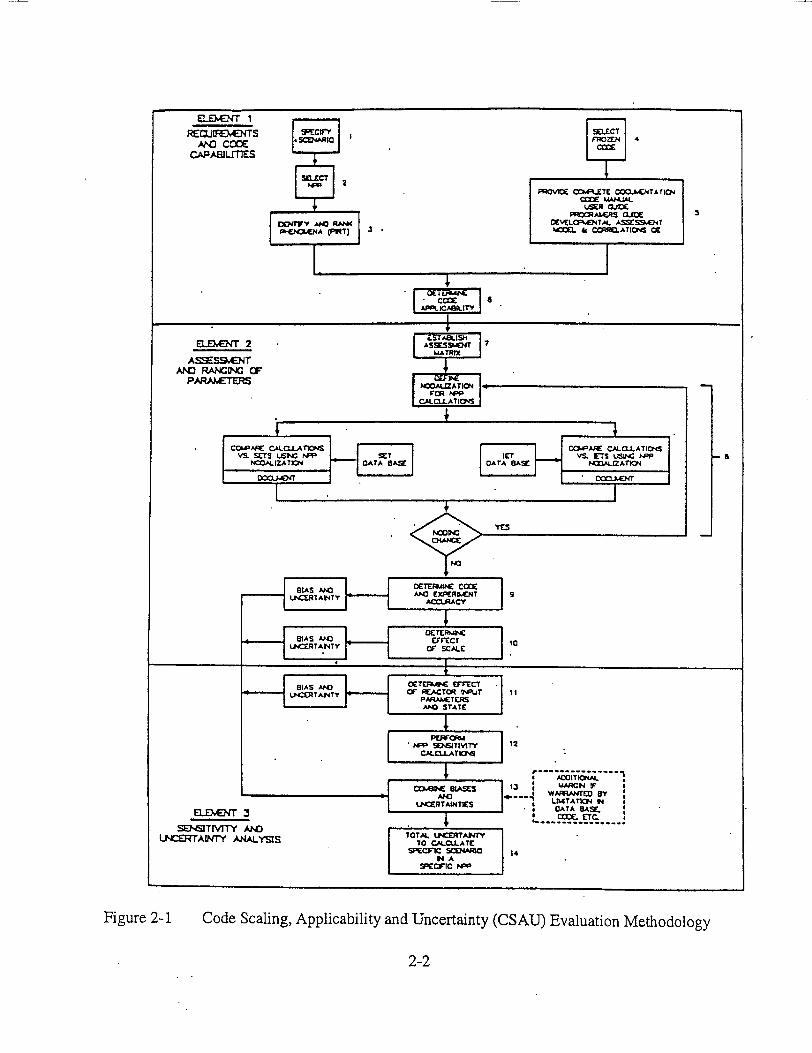
Code Scaling, Applicability and Uncertainty (CSAU) Evaluation Methodology
2-2
Figure 2-1
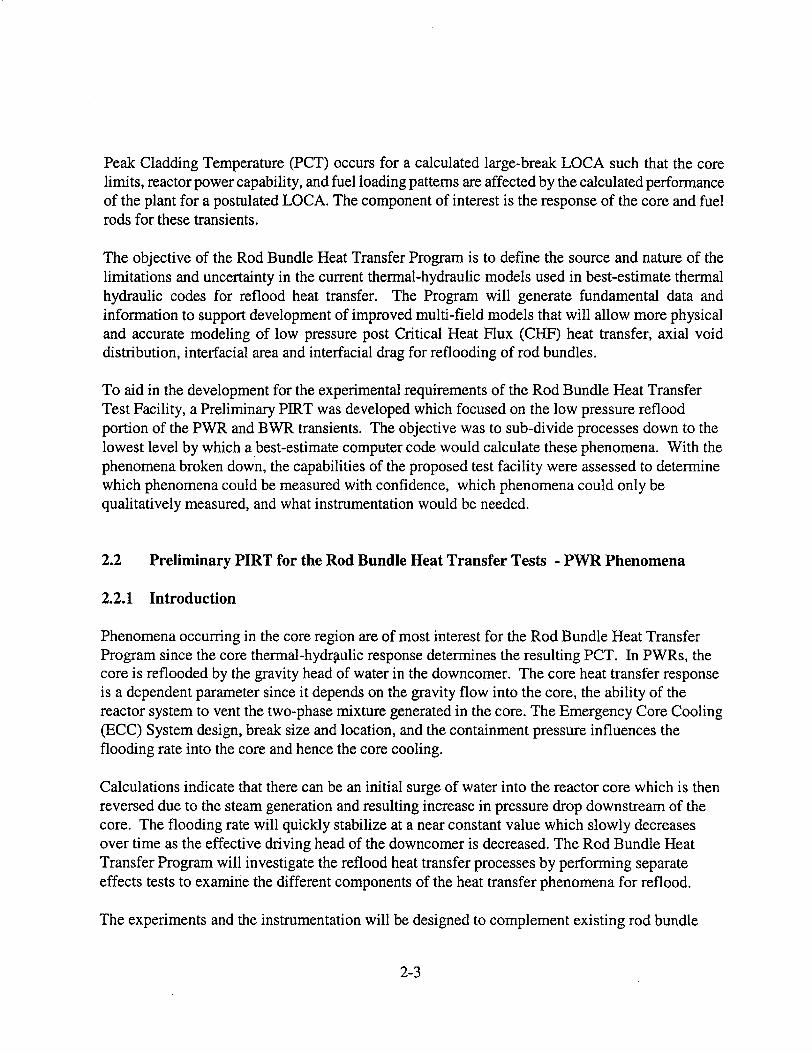
Peak Cladding Temperature (PCT) occurs for a calculated large-break LOCA such that the core limits, reactor power capability, and fuel loading patterns are affected by the calculated performance of the plant for a postulated LOCA. The component of interest is the response of the core and fuel rods for these transients.
The objective of the Rod Bundle Heat Transfer Program is to define the source and nature of the limitations and uncertainty in the current thermal-hydraulic models used in best-estimate thermal hydraulic codes for reflood heat transfer. The Program will generate fundamental data and information to support development of improved multi-field models that will allow more physical and accurate modeling of low pressure post Critical Heat Flux (CHF) heat transfer, axial void distribution, interfacial area and interfacial drag for reflooding of rod bundles.
To aid in the development for the experimental requirements of the Rod Bundle Heat Transfer Test Facility, a Preliminary PIRT was developed which focused on the low pressure reflood portion of the PWR and BWR transients. The objective was to sub-divide processes down to the lowest level by which a best-estimate computer code would calculate these phenomena. With the phenomena broken down, the capabilities of the proposed test facility were assessed to determine which phenomena could be measured with confidence, which phenomena could only be qualitatively measured, and what instrumentation would be needed.
2.2 Preliminary PIRT for the Rod Bundle Heat Transfer Tests - PWR Phenomena
2.2.1 Introduction
Phenomena occurring in the core region are of most interest for the Rod Bundle Heat Transfer Program since the core thermal-hydraulic response determines the resulting PCT. In PWRs, the core is reflooded by the gravity head of water in the downcomer. The core heat transfer response is a dependent parameter since it depends on the gravity flow into the core, the ability of the reactor system to vent the two-phase mixture generated in the core. The Emergency Core Cooling (ECC) System design, break size and location, and the containment pressure influences the flooding rate into the core and hence the core cooling.
Calculations indicate that there can be an initial surge of water into the reactor core which is then reversed due to the steam generation and resulting increase in pressure drop downstream of the core. The flooding rate will quickly stabilize at a near constant value which slowly decreases over time as the effective driving head of the downcomer is decreased. The Rod Bundle Heat Transfer Program will investigate the reflood heat transfer processes by performing separate effects tests to examine the different components of the heat transfer phenomena for reflood.
The experiments and the instrumentation will be designed to complement existing rod bundle
2-3

data and to provide unique data and insights into the thermal-hydraulic phenomena such that the existing data and the new data to be gathered in the program can be more effectively utilized for computer code validation. In this fashion, the existing rod bundle database will become more valuable and can be integrated with the new data. The experiments will be structured so as to separate out the individual phenomena which have been identified in the preliminary Phenomena Identification and Ranking Table. The experiments include:
* Heat loss experiments to characterize the facility for mass and energy balances;
0 Single phase pressure drop experiments to characterize rod bundle and spacer grid pressure losses;
0 Radiation heat transfer tests in an evacuated bundle to characterize the rod-to-rod radiation heat transfer, surface emissivity, and the rod-to-housing heat transfer;
* Convection to superheated steam to examine the rod bundle convective heat transfer over a wide range of Reynolds numbers and single phase heat transfer for enhancement by spacer grids;
* Convection to superheated steam with droplets injection to examine the effects of the entrained drops on vapor temperatures due to evaporation, the development and change of the interfacial area for heat and mass transfer along the length of the bundle, effects of the drops on the convective heat transfer, radiation heat transfer to the drops on vapor, spacer grid effects on droplet breakup, vapor de-superheating and grid quenching.
Forced reflooding experiments over a wide range of conditions of flow, pressure, inlet subcooling, initial rod temperature, and rod powers to overlap with existing forced reflood data, with the emphasis on the entrainment mechanisms at the quench front
Variable reflooding experiments over a range of conditions of flow, pressure, inlet subcooling, initial rod temperatures, rod powers, and outlet liquid and vapor flows to overlap with existing reflood data.
2-4

2.2.2 Development of the Classifications for the Different Regions for the Rod Bundle Heat Transfer Program Preliminary PIRT
The Preliminary PIRT for the Rod Bundle Heat transfer Program was developed by examining the different components in the reactor system for a PWR to identify the key phenomena. The core region is the focus of this program to obtain data to improve heat transfer models. The remainder of the reactor system components will also be discussed and the phenomena will be identified.
The approach for developing the Preliminary PIRT for the core region is based on examining the FLECHT-SEASET (24) test data and analysis. Figures 2-2 to 2-4 show the quench front curve and the two-phase froth region, which is above the quench front, for different flooding rates at the same pressure and bundle power. A schematic of the flow regimes at and above the quench front is shown in Figure 2-5. This figure gives a clearer indication of the flow behavior for the region above the quench front and below the dispersed flow film-boiling region.
Using Figures 2-2 to 2-5 as guides, six regions of interest are identified within the core during reflooding. At the bottom of the fuel rod (or heater rods in the experiment), the heat transfer is by single phase forced or natural convection. As the coolant temperature approaches the saturation temperature, subcooled nucleate boiling begins, and eventually saturated boiling. The quench front is the next region of interest. At this point, the stored energy in the fuel or heater rods is released into the coolant resulting in significant steam generation.
The local rod temperature decreases from the minimum film boiling point to the critical heat flux temperature and into nucleate boiling. Local temperature decreases in this region are several hundred degrees over a short distance such that a substantial volume of steam is generated. The steam generated near the quench front entrains liquid.
The froth region above the quench front is the location where the steam generated near the quench front shears the liquid flow into liquid ligaments and eventually into a spectrum of droplets which are entrained upwards. Above the froth region, the flow field consists of the entrained droplets in a superheated steam flow. This is the heat transfer regime where the calculated PCT typically occurs. It is a region of low heat transfer since the vapor sink temperature becomes superheated and approaches the rod surface temperature. Since temperatures are high, radiation heat transfer to surfaces, droplets, and vapor must be accounted for, as indicated by the FLECHT-SEASET experiments.
At the very top of the rod bundle, there can be a second quench front which moves down the fuel/heater rod. The movement of the top quench front depends on the amount of liquid entrainment in the flow and the power profile of the fuel/heater rod as well as the previous
2-5

blowdown heat transfer history. Assuming that there is sufficient entrained liquid in the flow which can be deposited, the top quench front is an axial conduction progression down the fuel/heater rod. The excess liquid flow from the downward liquid film flow is sputtered-off into the up flowing steam and is re-entrained with droplets from below. The top quench occurs at elevations significantly above the location of the PCT so its behavior does not influence the PCT value directly. However, the top quench front will affect the amount of liquid which leaves the core and affects the system reflood behavior.
The exact nature of the six regions are a function of the flooding rate into the core, system pressure, core power level, inlet subcooling and the rod bundle initial temperature. As the flooding rate increases, the single-phase convection region increases; there is reduced subcooled nucleate boiling and no saturated boiling. The height of the froth region above the quench front increases with increased flooding rates into the bundle as shown in Figures 2-2 to 2-5. As the froth region increases in size, the dispersed flow film-boiling region decreases and the resulting vapor superheat in this region is reduced and higher heat transfer rates result. Also, the top down quench front is enhanced because of the additional liquid in the entrained flow.
Since there are different regions in the core during reflooding, with perhaps different phenomena which are important, the core was subdivided into six regions for the preliminary PIRT and phenomena identified for each. There may be overlap in the phenomena; however, different phenomena can have a different weighting for the different regions. The six regions identified are:
a) single phase heat transfer region below the quench front;
b) subcooled nucleate boiling and saturated boiling region below the quench front;
c) quench front region where the heat is released from the quenching fuel rods;
d) froth region where the entrained liquid is sheared into droplets;
e) dispersed flow film boiling region above the froth region where the PCT occurs; and
f) top down quench front.
Separate preliminary PIRTs were developed for each of these core regions such that the particular phenomena for a particular region could be subdivided into specific component models which a computer code uses to perform the reflood calculation. The same ranking method as that employed by Los Alamos will be used to denote the relative importance of the "high", "Medium", and "Low" phenomena. The preliminary PIRTs for the core for each region are given in Tables 2-1 to 2-6. These PIRTs will be used to develop and guide the design of the Rod Bundle Heat Transfer Test Facility for the Single Phase Convection, Radiation Heat Transfer, Single Phase Steam with droplet injection, and the forced reflooding tests.
2-6

In addition to the forced flooding, experiments will be performed to simulate the effects of the gravity reflood. Previous large-break LOCA PIRTs were reviewed to determine the most important system components which can affect the core thermal response during reflood. Table 2-7 lists those components designated as having a HIGH ranking by the Los Alamos and the Westinghouse PIRTs, along with the ranking as developed in this program. Many of the components listed in Table 2-7 will not be simulated in the Rod Bundle Heat Transfer test facility since the primary focus is for separate-effects tests. However, variable reflood tests can be performed in which the effects of the most important system parameters can be assessed as discussed in Table 2-7. The injection flows, system pressure and the effects of the different core inlet ECC temperatures can be simulated. Steam binding due to additional evaporation of liquid carried to the generators, which are not modeled in the test facility, can be simulated with the selected variable inlet flooding rate. In this table, it is already assumed that the core component is a highly ranked parameter and the focus will be on the reactor system components.
2-7

Z=Z 1
T Ie
tf tq
TIME
TRANSITION ZONE FRONT CURVE LENGTH 0!
QUENCH C
I I
tf tq
Figure 2-2 Froth Region and Quench Front Locations for Reflood
F N ZONE
;URVE
2-8

0 100 200 300 400 500 600 700 800 TIME (sec)
Froth Front and Quench Front Curves for FLECHT-SEASET Run 40 psia Test
31203, 1.5 in/sec,
2-9
1250
0
q
LU
0U
1000
750
500
250
0 -
300
250
200
150
100
2282
2000
IR
w 1500 cc
c
1000 .
LU
500
32
52.8
LU
40 LL
U.
30 U'
20 '0 '=
a: 10
lU m0
0 N
E
z LU
LL
LU 0
LU EL
I-
I-50
0
Figure 2-3
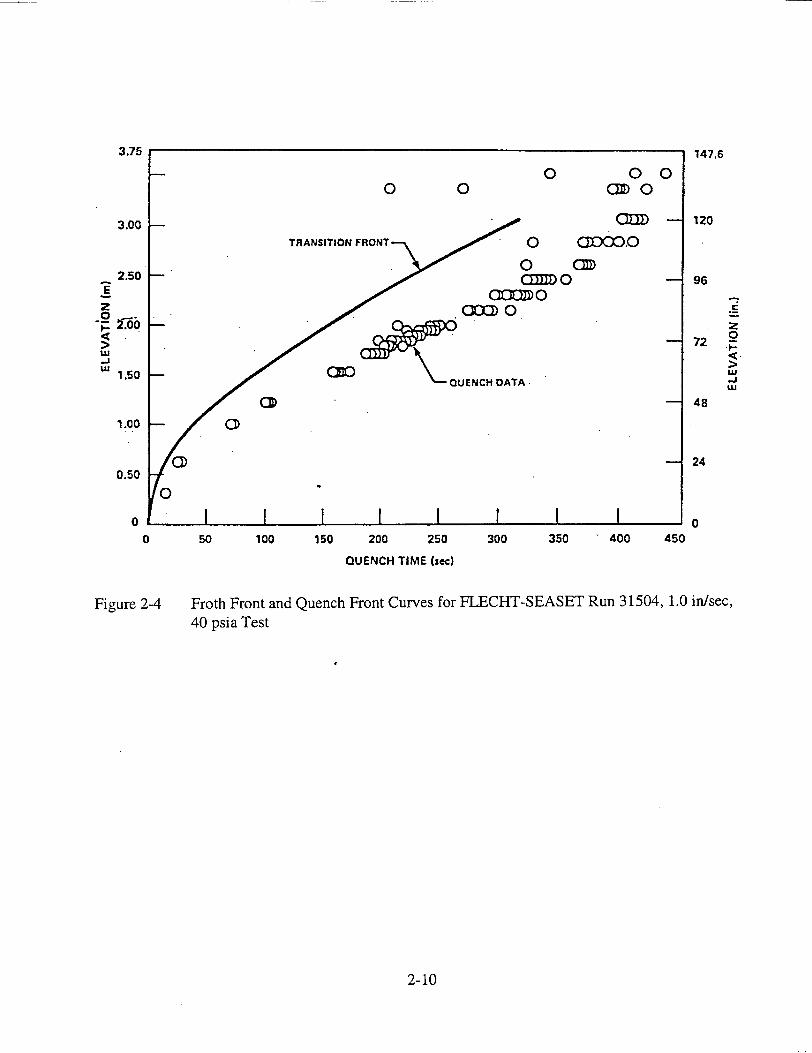
147.6
3.00 UU) - 120
TRANSITION FRONTQ 0 GCID=O
2.50D 0 96
> 72
"""0
LU >
1.50 QUENCH DATA.
1.0 -- CD
S24 0.50
0
0 I 0 50 100 150 200 250 300 350 400 450
QUENCH TIME (sec)
Figure 2-4 Froth Front and Quench Front Curves for FLECHT-SEASET Run 31504, 1.0 in/sec, 40 psia Test
2-10
3.75
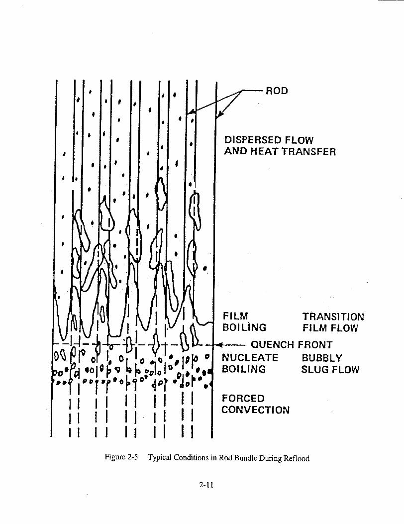
ROD
DISPERSED FLOW AND HEAT TRANSFER
TRANSITION FILM FLOW
QUENCH FRONTNUCLEATE BOILING
BUBBLY SLUG FLOW
,I ,,I II FORCED II i II CONVECTION
IF 2 I iI II Figure 2-5 Typical Conditions in Rod Bundle During Reflood
2-11
ii I II 1 II I

Table 2 - 1 Single Phase Liquid Convective Heat Transfer
Process/Phenomena Ranking Basis RBHT
- Effects of Geometry L Limited data exists which can be used as a guide, There is little data for natural convection in rod bundles, usually Gr/Re2<<l. should have little uncertainty on PCT.
- Convective Heat Transfer M 1 (p Convective H.T. data has been correlated for Will measure Ts, Tf and power below quench front so forced convective H.T. or natural rod bundles, uncertainty will not affect PCT, can convection H.T. can be calculated. affect point of boiling.
- Effects of Geometry L De has been shown to be acceptable for P/D of 1.3 There is little data for natural convection in rod bundles, usually Gr/Re 2 <<I. (2-5). Limited data exists which can be used as a
guide, should have little uncertainty on PCT
- Effects of Spacers L Effects of spacers in lw convective H.T. is known, Effects will be measured, with proper placement of heater rod T/C's and fluid T/C's. see (2-6). No impact on PCT uncertainty. Effect unknown for natural convection, but enhances H.T. No impact on PCT uncertainty.
- Effects of Properties L Property effects are accounted for in analysis for Property effects can be calculated from T, and Tb.
lip H.T. little uncertainty.
- Liquid Velocity (Reynolds Number) M Determine convective heat transfer, onset of Will measure total flow, Tw, Tf, can calculate heat transfer from data and correlate. boiling
- Liquid Subcooling M Liquid is heat sink, determine point of boiling Fluid temperatures will be measured with miniature steam probes, selected T/C's can traverse.
- Decay Power H Source of energy for rods, boundary condition for Will be simulated. test
2-12

Table 2-2 Subcooled and Saturated Boining - The Core Component Below the Quench Front
Process/Phenomena Ranking Basis RBHT Program
- Subcooled Boiling heat transfer and heat M A significant variation in the subcooled Will measure rod temperature (surface) local fluid temperatures (selectively) and power such flux, split of energy between liquid and boiling H.T. coefficient will not affect that total wall heat flux can be calculated. Bundle average quality can be calculated from an vapor production the PCT uncertainty since rod is energy balance. Codes that use the Chen Model (8) which has a superposition of convection and
quenched. Will effect energy partition to boiling. The RBHT can be used to test this type of correlation since both Ts and q" are sensible heat and vapor generation. measured. However, it will be difficult, if not impossible, to directly determine the heat flux
split between convection and boiling without using the correlation.
-Effects of Geometry, P/D, De L Boiling effects in rod bundles have been The void fraction will be measured along the test section using AP cells, and at fixed locations heater and properties correlated for our P/D, De range with with a soft gamma ray detector.
acceptable uncertainty (25)(26)
-Effects of Spacers L Locally enhances H.T.; Correlations/ Effects of spacer grids can be measured with the proper T/C placement. Models are available, acceptable
(2-7) uncertainty
-Effects of Fluid Properties L Data exists for our Range of Conditions, little uncertainty.
-Local Void Fraction M Data does exist for tubes and rod bundles The void fraction will be measured along the test section using AP cells, and at fixed locations with a low energy gamma ray detector.
- Liquid Subcooling M Determines the near wall condensation of Subcooling will be measured with miniature T/C's, and Traversing T/C's. vapor, energy split between sensible, and net vapor production
- Interfacial Heat Transfer Area M Determines net vapor generation, Movies can be taken at different positions but very difficult to obtain interfacial area. near wall condensation May be able to see bubbles with laser.
2-13
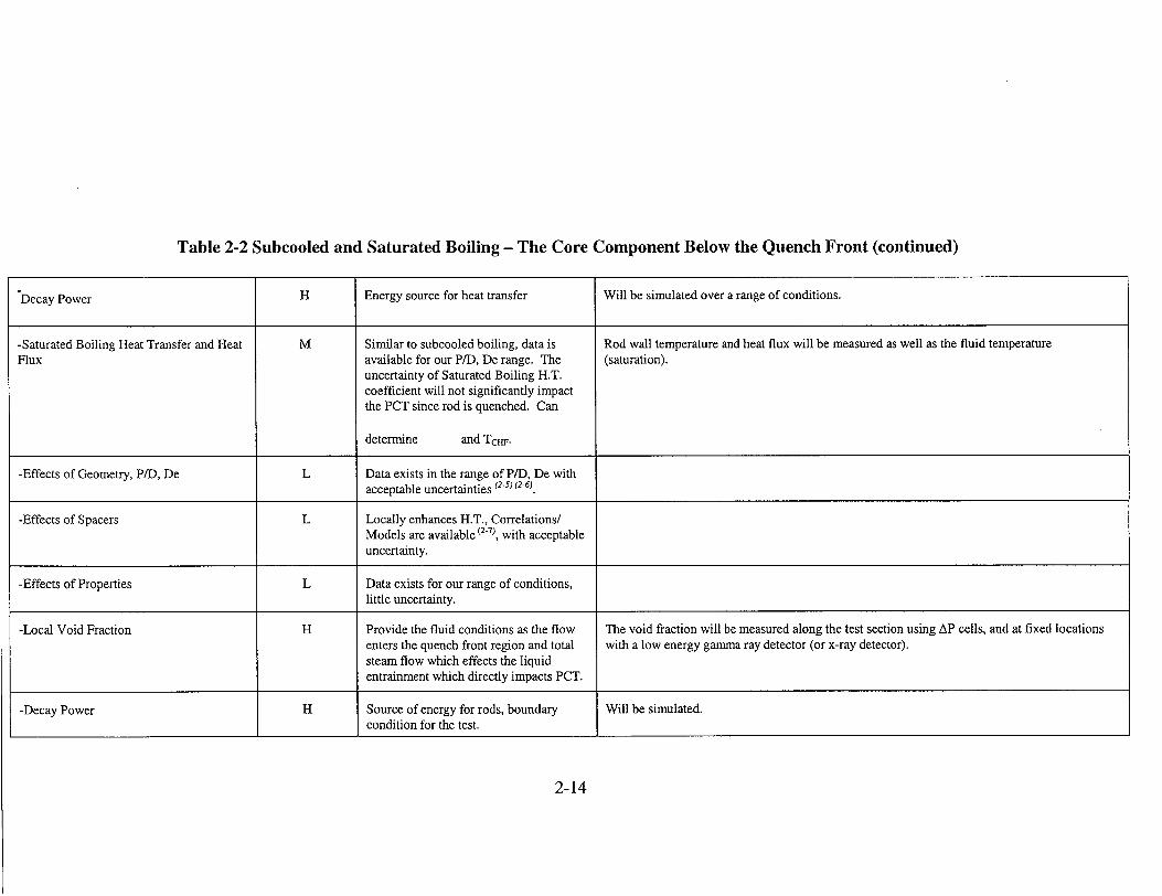
Table 2-2 Subcooled and Saturated Boiling - The Core Component Below the Quench Front (continued)
"Decay Power H Energy source for heat transfer Will be simulated over a range of conditions.
-Saturated Boiling Heat Transfer and Heat M Similar to subcooled boiling, data is Rod wall temperature and heat flux will be measured as well as the fluid temperature Flux available for our P/D, De range. The (saturation).
uncertainty of Saturated Boiling H.T. coefficient will not significantly impact the PCT since rod is quenched. Can
determine and TCHF.
-Effects of Geometry, P/D, De L Data exists in the range of P/D, De with acceptable uncertainties (2-S) (2-6)
-Effects of Spacers L Locally enhances H.T., Correlations/ Models are available (27), with acceptable uncertainty.
-Effects of Properties L Data exists for our range of conditions, little uncertainty.
-Local Void Fraction H Provide the fluid conditions as the flow The void fraction will be measured along the test section using AP cells, and at fixed locations enters the quench front region and total with a low energy gamma ray detector (or x-ray detector). steam flow which effects the liquid entrainment which directly impacts PCT.
-Decay Power H Source of energy for rods, boundary Will be simulated. condition for the test.
2-14
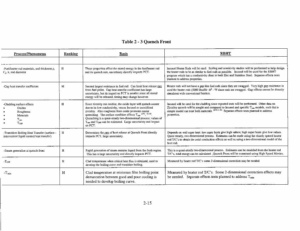
Table 2 - 3 Quench Front
Process/Phenomena Ranking Basis RBHT
-Fuel/heater rod materials, and thickness p, H These properties effect the stored energy in the fuel/heater rod Inconel Heater Rods will be used. Scaling and sensitivity studies will be performed to help design C0, k, rod diameter and its quench rate, uncertainty directly impacts PCT. the heater rods to be as similar to fuel rods as possible. Inconel will be used for the RBHT
program which has a conductivity close to both Zirc and Stainless Steel. Separate effects tests planned to address properties.
-Gap heat transfer coefficient M Second largest resistance in fuel rod. Can limit heat release rate Heater rods will not have a gap like fuel rods since they are swagged. Very high gap resistance is from fuel pellet. Gap heat transfer coefficient has large used for heater rods (5000 Btu/Hr -ft2 - °F since rods are swagged. Gap effects cannot be directly uncertainty, but its impact on PCT is smaller since all stored simulated with conventional heaters. energy will be released, timing may change however.
-Cladding surface effects H Since zircaloy can oxidize, the oxide layer will quench sooner Inconel will be used for the cladding since repeated tests will be performed. Other data on
Oxides due to its low conductivity, versus Inconel or unoxidized Zircaloy quench will be sought and compared to Inconel and specific T,,., models, such that a
Roughness zircaloy. Also roughness from oxide promotes easier simple model can treat both materials. (2-9.2. 10) Separate effects tests planned to address
* Materials quenching. The surface condition affects T_, (2-9), (2•10) properties.
• T,, Quenching is a quasi-steady two-dimensional process; values of
* TcHF Ta,. and TcHF can be estimated. Large uncertainty and impact on PCT.
-Transition Boiling Heat Transfer (surface - H Determines the rate of heat release at Quench Front directly Depends on wall super heat: low super heats give high values; high super heats give low values. intermittent liquid contact heat transfer) impacts PCT, large uncertainty. Quasi-steady, two-dimensional process. Estimates can be made using the closely spaced heater
rod T/C's to obtain the axial conduction effects as well as using a two-dimensional model of the heat rod.
-Steam generation at quench front H Rapid generation of steam entrains liquid from the froth region. This is a quasi-steady two-dimensional process. Estimates can be modeled from the heater rod This has a large uncertainty and directly impacts PCT. T/C's, total energy can be calculated. -Quench Front will be examined using High Speed Movies.
-Tci H Clad temperature when critical heat flux is obtained, used to Measured by heater rod T/C's some 2-dimensional correction may be needed. develop the boiling curve and transition boiling.
-Tmin H Clad temperature at minimum film boiling point Measured by heater rod T/C's. Some 2-dimensional correction effects may demarcation between good and poor cooling is be needed. Separate effects tests planned to address T~n
needed to develop boiling curve.
2-15
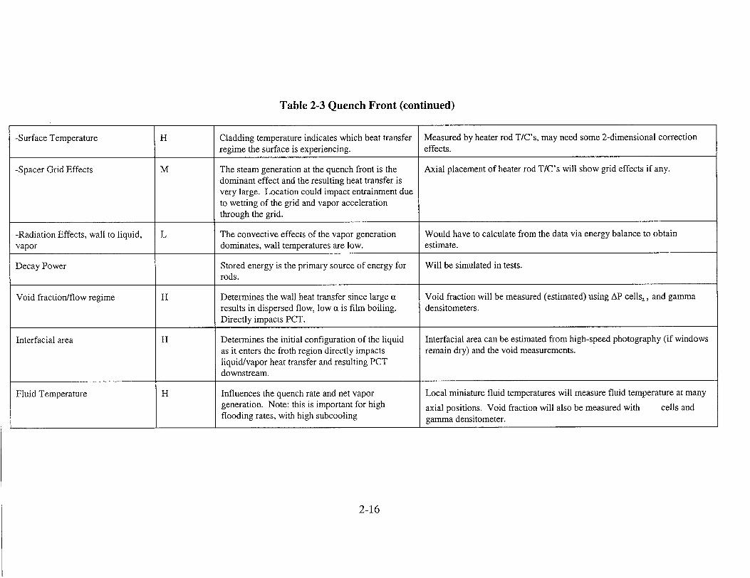
Table 2-3 Quench Front (continued)
-Surface Temperature H Cladding temperature indicates which heat transfer Measured by heater rod T/C's, may need some 2-dimensional correction
regime the surface is experiencing, effects.
-Spacer Grid Effects M The steam generation at the quench front is the Axial placement of heater rod T/C's will show grid effects if any. dominant effect and the resulting heat transfer is very large. Location could impact entrainment due to wetting of the grid and vapor acceleration
through the grid.
-Radiation Effects, wall to liquid, L The convective effects of the vapor generation Would have to calculate from the data via energy balance to obtain vapor dominates, wall temperatures are low. estimate.
Decay Power Stored energy is the primary source of energy for Will be simulated in tests. rods.
Void fraction/flow regime H Determines the wall heat transfer since large a Void fraction will be measured (estimated) using AP cells., and gamma results in dispersed flow, low a is film boiling, densitometers.
Directly impacts PCT.
Interfacial area H Determines the initial configuration of the liquid Interfacial area can be estimated from high-speed photography (if windows as it enters the froth region directly impacts remain dry) and the void measurements. liquid/vapor heat transfer and resulting PCT
downstream.
Fluid Temperature H Influences the quench rate and net vapor Local miniature fluid temperatures will measure fluid temperature at many
generation. Note: this is important for high axial positions. Void fraction will also be measured with cells and flooding rates, with high subcooling gamma densitometer.
2-16
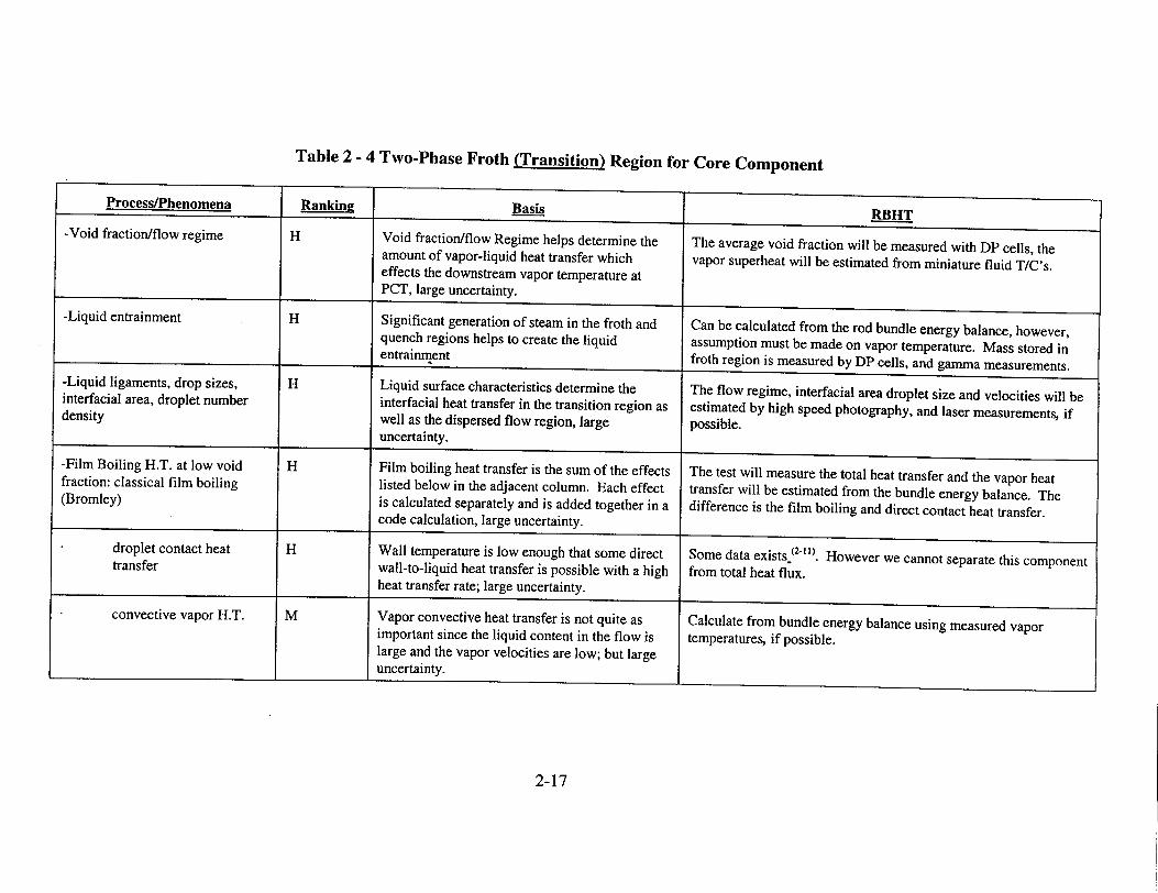
Table 2 - 4 Two-Phase Froth (Transition) Region for Core Component
Process/Phenomena
-Void fraction/flow regime
-Liquid entrainment
-Liquid ligaments, drop sizes, interfacial area, droplet number density
-Film Boiling H.T. at low void fraction: classical film boiling (Bromley)
droplet contact heat transfer
convective vapor H.T.
Basis 7
Ranking
H
4. 1
H
I r I
Void fraction/flow Regime helps determine the amount of vapor-liquid heat transfer which effects the downstream vapor temperature at PCT, large uncertainty.
Significant generation of steam in the froth and quench regions helps to create the liquid entrainment
H
i TH
J __ _ _ _ _ -
H
M
Liquid surface characteristics determine the interfacial heat transfer in the transition region as well as the dispersed flow region, large uncertainty.
Film boiling heat transfer is the sum of the effects listed below in the adjacent column. Each effect is calculated separately and is added together in a code calculation, large uncertainty.
Wall temperature is low enough that some direct wall-to-liquid heat transfer is possible with a high heat transfer rate; large uncertainty.
Vapor convective heat transfer is not quite as important since the liquid content in the flow is large and the vapor velocities are low; but large uncertainty.
RBHT
The average void fraction will be measured with DP cells, the vapor superheat will be estimated from miniature fluid T/C's.
Can be calculated from the rod bundle energy balance, however, assumption must be made on vapor temperature. Mass stored in froth region is measured by DP cells, and gamma measurements.
The flow regime, interfacial area droplet size and velocities will be estimated by high speed photography, and laser measurements, if possible.
The test will measure the total heat transfer and the vapor heat transfer will be estimated from the bundle energy balance. The difference is the film boiling and direct contact heat transfer.
Some data exists (21 .)* However we cannot separate this component from total heat flux.
Calculate from bundle energy balance using measured vapor temperatures, if possible.
2-17
_________ U _______________________________ I __________
Basis
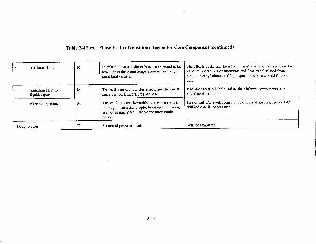
Table 2-4 Two -Phase Froth (Transition) Region for Core Component (continued)
interfacial H.T. M Interfacial heat transfer effects are expected to be The effects of the interfacial heat transfer will be inferred from the small since the steam temperature is low, large vapor temperature measurements and flow as calculated from uncertainty exists. bundle energy balance and high speed movies and void fraction
data.
radiation H.T. to M The radiation heat transfer effects are also small Radiation tests will help isolate the different components, can
liquid/vapor since the rod temperatures are low. calculate from data.
effects of spacers M The veldcities and Reynolds numbers are low in Heater rod T/C's will measure the effects of spacers, spacer T/C's
this region such that droplet breakup and mixing will indicate if spacers wet. are not as important. Drop deposition could occur.
-Decay Power H Source of power for rods. Will be simulated.
2-18
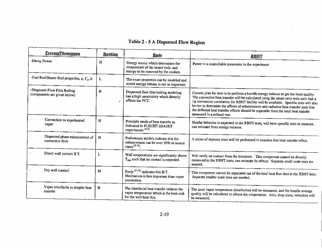
Table 2 - 5 A Dispersed Flow Region
Process/Phenomena
-Decay Power
-Fuel Rod/Heater Rod properties, p, Cp, k
-Dispersed Flow Film Boiling (components are given below)
Convection to superheated vapor
Dispersed phase enhancement of convective flow
Direct wall contact H.T.
Dry wall contact'
Vapor interfacial to droplet heat transfer
IHRankin
H
L
H
H
H
L
M
H
BasisEnergy source which determines the temperature of the heater rods, and energy to be removed by the coolant.
RBH
The exact properties can be modeled and stored energy release is not as important
Dispersed flow film boiling modeling has a high uncertainty which directly effects the PCT.
Principle mode of heat transfer as indicated in FLECHT-SEASET experiments (2.4)
Preliminary models indicate that the enhancement can be over 50% in source cases (2-13).
Wall temperatures are significantly above Tra such that no contact is expected.
lloeje (2-12) indicates this H.T. Mechanism is less important than vapor convection.
The interfacial heat transfer reduces the vapor temperature which is the heat sink
for the wall heat flux 1,
Power is a controllable parameter in the experiment
Current plan for tests is to perform a bundle energy balance to get the local quality. The convective heat transfer will be calculated using the steam only tests such that a lIp convective correlation for RBHT facility will be available. Specific tests will also be run to determine the affects of enhancement and radiation heat transfer such that the different heat transfer effects should be separable from the total heat transfer measured in a reflood test.measure inarfooetSimilar behavior is expected in the RBHT tests, will have specific tests to measure, can estimate from energy balance.
-t A series of separate tests will be performed to examine this heat transfer effect.
Will verify no contact from the literature. This component cannot be directly measured in the RBHT tests; can estimate its effects. Separate small scale tests are needed.needed.
This component cannot be separated out of the total heat flux data in the RBHT tests. Separate smaller scale tests are needed.
The axial vapor temperature distribution will be measured, and the bundle average quality will be calculated to obtain the evaporation. Also, drop sizes, velocities will
2-19
I I
I - i
Basis RBHT
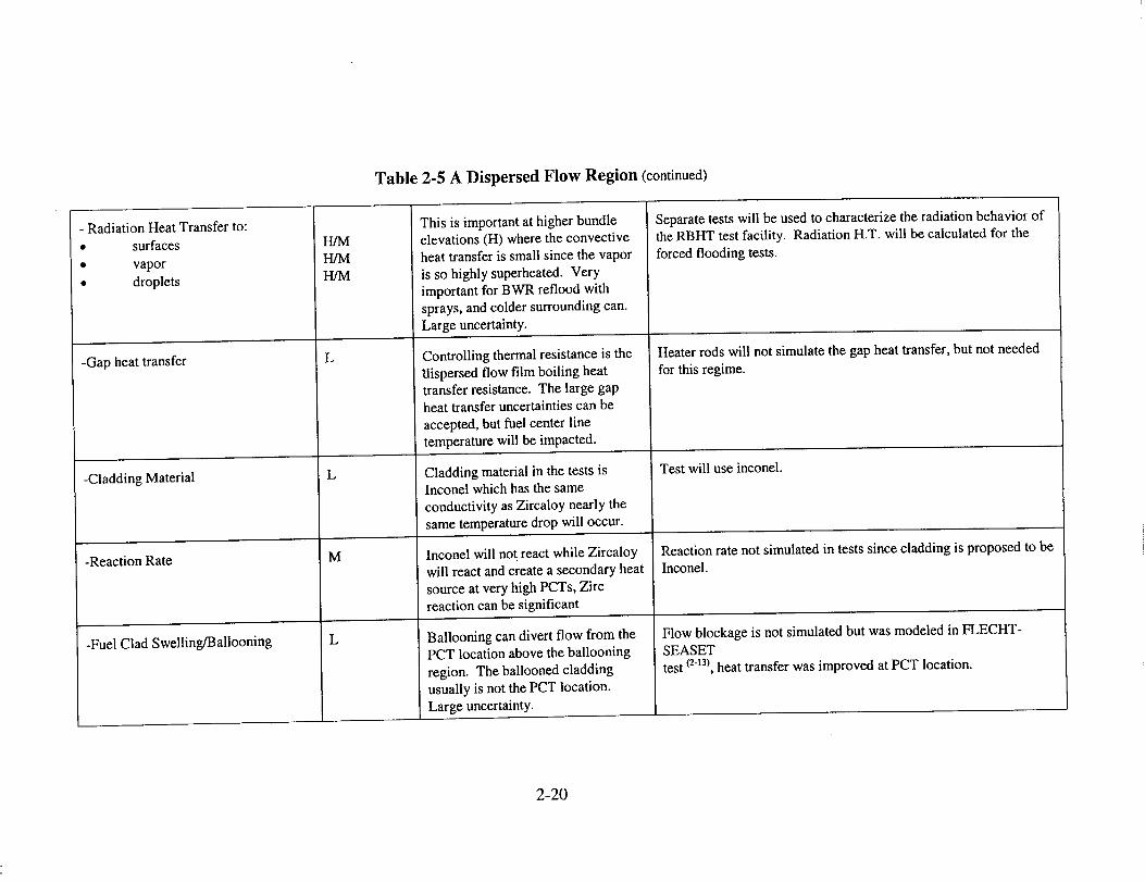
Table 2-5 A Dispersed Flow Region (continued)
- Radiation Heat Transfer to: * surfaces * vapor * droplets
-Gap heat transfer
-Cladding Material
-Reaction Rate
-Fuel Clad Swelling/Ballooning
This is important at higher bundle elevations (H) where the convective heat transfer is small since the vapor
is so highly superheated. Very important for BWR reflood with sprays, and colder surrounding can. Large uncertainty.
Controlling thermal resistance is the "dispersed flow film boiling heat
transfer resistance. The large gap heat transfer uncertainties can be accepted, but fuel center line temperature will be impacted.
Cladding material in the tests is Inconel which has the same conductivity as Zircaloy nearly the
same temperature drop will occur.
Inconel will not react while Zircaloy will react and create a secondary heat source at very high PCTs, Zirc reaction can be significant
Ballooning can divert flow from the
PCT location above the ballooning region. The ballooned cladding usually is not the PCT location. Large uncertainty.
-I-
-I
Separate tests will be used to characterize the radiation behavior of the RBHT test facility. Radiation H.T. will be calculated for the
forced flooding tests.
Heater rods will not simulate the gap heat transfer, but not needed for this regime.
Test will use inconel.
Reaction rate not simulated in tests since cladding is proposed to be Inconel.
Flow blockage is not simulated but was modeled in FLECHTSEASET test (2-13), heat transfer was improved at PCT location.
2-20
I
I
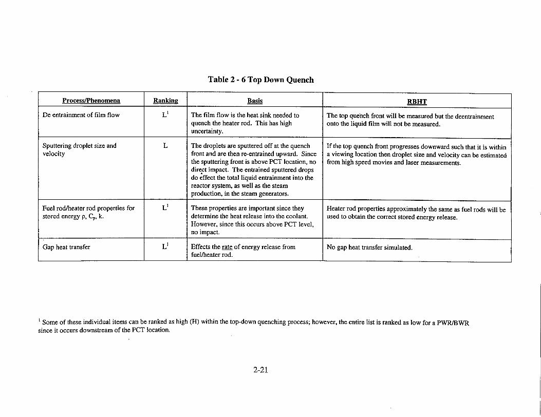
Table 2 - 6 Top Down Quench
S Some of these individual items can be ranked as high (H) within the top-down quenching process; however, the entire list is ranked as low for a PWR/BWR since it occurs downstream of the PCT location.
2-21
Process/Phenomena Ranking Basis RBHT
De entrainment of film flow L' The film flow is the heat sink needed to The top quench front will be measured but the deentrainment quench the heater rod. This has high onto the liquid film will not be measured. uncertainty.
Sputtering droplet size and L The droplets are sputtered off at the quench If the top quench front progresses downward such that it is within velocity front and are then re-entrained upward. Since a viewing location then droplet size and velocity can be estimated
the sputtering front is above PCT location, no from high speed movies and laser measurements. direct impact. The entrained sputtered drops do effect the total liquid entrainment into the reactor system, as well as the steam production, in the steam generators.
Fuel rod/heater rod properties for L' These properties are important since they Heater rod properties approximately the same as fuel rods will be stored energy p, CP, k. determine the heat release into the coolant. used to obtain the correct stored energy release.
However, since this occurs above PCT level, no impact.
Gap heat transfer Ll Effects the rate of energy release from No gap heat transfer simulated. fuel/heater rod.
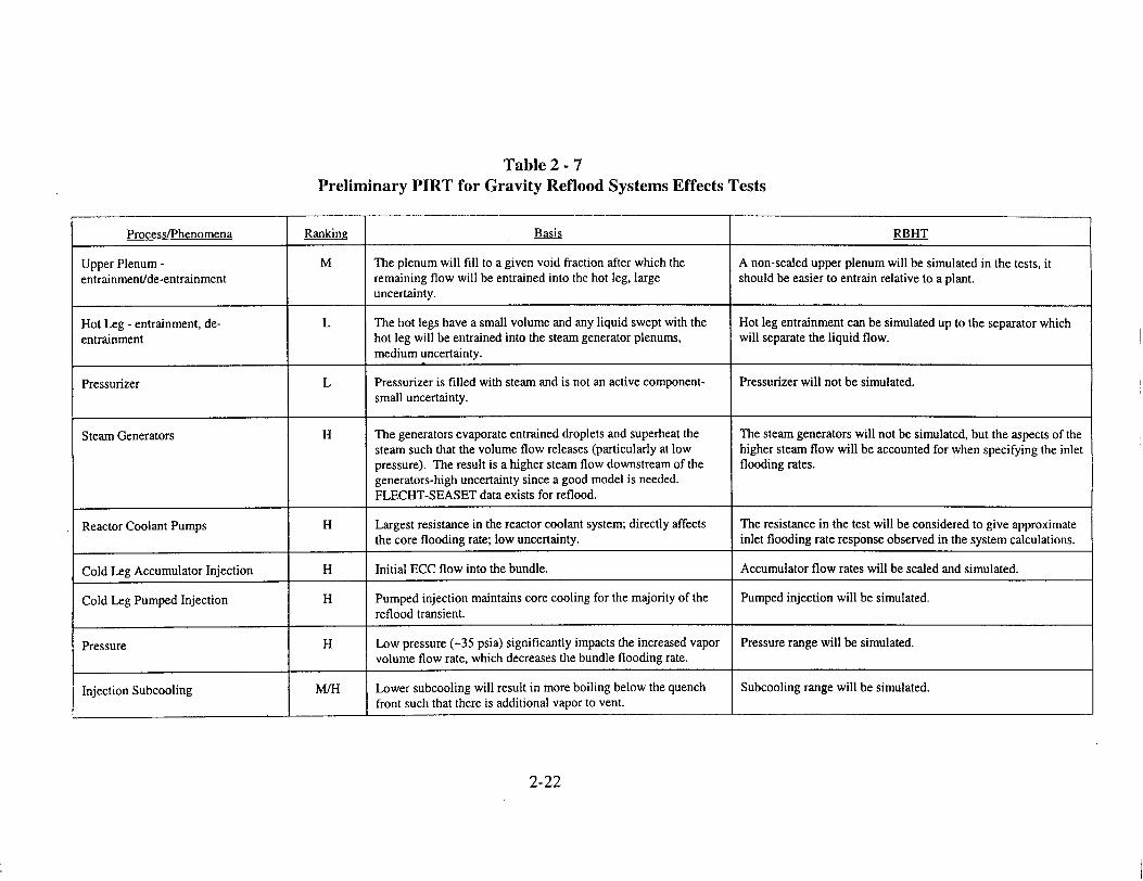
Table 2 - 7 Preliminary PIRT for Gravity Reflood Systems Effects Tests
Process/Phenomena Ranking Basis RBHT
Upper Plenum - M The plenum will fill to a given void fraction after which the A non-scaled upper plenum will be simulated in the tests, it entrainment/de-entrainment remaining flow will be entrained into the hot leg, large should be easier to entrain relative to a plant.
uncertainty.
Hot Leg - entrainment, de- L The hot legs have a small volume and any liquid swept with the Hot leg entrainment can be simulated up to the separator which entrainment hot leg will be entrained into the steam generator plenums, will separate the liquid flow.
medium uncertainty.
Pressurizer L Pressurizer is filled with steam and is not an active component- Pressurizer will not be simulated. small uncertainty.
Steam Generators H The generators evaporate entrained droplets and superheat the The steam generators will not be simulated, but the aspects of the steam such that the volume flow releases (particularly at low higher steam flow will be accounted for when specifying the inlet pressure). The result is a higher steam flow downstream of the flooding rates. generators-high uncertainty since a good model is needed. FLECHT-SEASET data exists for reflood.
Reactor Coolant Pumps H Largest resistance in the reactor coolant system; directly affects The resistance in the test will be considered to give approximate the core flooding rate; low uncertainty, inlet flooding rate response observed in the system calculations.
Cold Leg Accumulator Injection H Initial ECC flow into the bundle. Accumulator flow rates will be scaled and simulated.
Cold Leg Pumped Injection H Pumped injection maintains core cooling for the majority of the Pumped injection will be simulated. reflood transient.
Pressure H Low pressure (-35 psia) significantly impacts the increased vapor Pressure range will be simulated. volume flow rate, which decreases the bundle flooding rate.
Injection Subcooling M/H Lower subcooling will result in more boiling below the quench Subcooling range will be simulated. front such that there is additional vapor to vent.
2-22
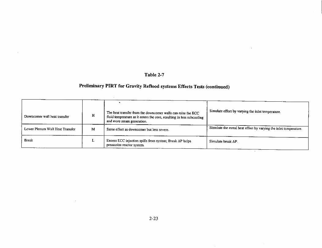
Table 2-7
Preliminary PIRT for Gravity Reflood systems Effects Tests (continued)
Downcomer wall heat transfer
Lower Plenum Wall Heat Transfer
Break
The heat transfer from the downcomer walls can raise the ECC Simulate effect by varying the inlet temperature.
fluid temperature as it enters the core, resulting in less subcooling and more steam generation.
Same effect as downcomer but less severe. Simulate the metal heat effect by varying the inlet temperature.
Excess ECC injection spills from system; Break AP helps Simulate break AP. pressurize reactor system.
2-23
2.3 PIRT for Rod Bundle Heat Transfer Tests - BWR Phenomena
2.3.1 Introduction
Best estimate calculations for a BWR-6 plant were reviewed (2-14). The calculations indicated that once the vessel was depressurized, a three-dimensional flow pattern would be established in which there was downflow at the core edge through the low powered assemblies since the counter current flow was less limiting at these locations, and upflow in the hotter high power fuel assemblies.. The bypass region also helped direct the spray flow down from the upper plenum to the lower plenum. The highest powered assemblies were calculated to be in co-current upflow for the majority of the transient such that they reflooded in a very similar manner as a PWR hot assembly. The high power assemblies generated sufficient steam flow such that they remained above the flooding limit at the top of the fuel assembly and very little, if any, water penetrated into the assembly from the upper plenum.
2.3.2 BWR Reflood Phenomena of Interest
Nearly all the phenomena identified with rod bundle heat transfer for PWRs are applicable to the hot assembly in a BWR since it refloods in a similar manner. However, one difference between the reflooding behavior of the high power BWR assemblies and a PWR assembly is the presence of the fuel assembly shroud or channel in the BWR design. The shroud is calculated to quench from the liquid in the bypass region so there is more surface-to-surface radiation heat transfer occurring in the BWR fuel assembly compared to a PWR fuel assembly. The additional surface -to- surface radiation can be simulated in the RBHT experiments since the test facility will have a shroud around the test bundle.
Since the high power BWR fuel assemblies are in co-current upflow, similar to PWR fuel assemblies, the key thermal-hydraulic phenomena identified as being highly ranked in Tables 2-1 to 2-6 are also highly ranked for the BWR. The one factor which changes is the surface-to-surface radiation heat transfer in the dispersed flow film boiling regime. It is a higher ranked phenomena for BWRs than PWRs.
The highest ranked phenomena for the reflood period are summarized in Table 2-8. Comparing those ranked as HIGH in Tables 2-1 to 2-6 shows that the BWR hot assembly phenomena are captured.
2-24

Process/Phenomena-I
Core * Film Boiling
Upper Tie Plate CCFL
0 Channel-bypass Flow
T
T
Table 2 - 8 High Ranked BWR Core Phenomena
Basis RBHT
mined in film boiling period. Film boiling components will be measured.
y is in co-current up flow above CCFL Similar behavior to PWR reflooding.
will help cool the BWR fuel assembly The housing in the RBHT test will approximately simulate a BWR channel.
calculated to be in
PCT is deter:
Hot Assembl limit.
Flow bypass core.
S steam Cooling A portion of the dispersed flow film boiling heat Simulated in RBHT tests. transfer.
* Dryout Transition from nucleate boiling and film boiling. Simulated in RBHT tests, but hot assembly is upflow.
* Natural Circulation Flow Flow into the core and system pressure drops. Flow range can be simulated in RBHT.
Flow Regime
* Fluid Mixingt
Determines the nature and details of the heat transfer in the core.
Determines the liquid temperature in the upper plenum for CCFL break down.
-I.
Since pressures, heat flux, temperature, and flows can be simulated, flow regimes will also be simulated.
Not simulated in RBHT, but hot assembly is calculated to be in upflow.I. _______________________________
2-25
0
0
I
I
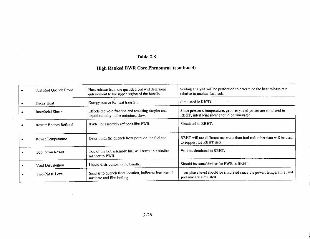
Table 2-8
High Ranked BWR Core Phenomena (continued)
2-26
* Fuel Rod Quench Front Heat release from the quench front will determine Scaling analysis will be performed to determine the heat release rate
entrainment to the upper region of the bundle. relative to nuclear fuel rods.
* Decay Heat Energy source for heat transfer. Simulated in RBHT.
* Interfacial Shear Effects the void fraction and resulting droplet and Since pressure, temperature, geometry, and power are simulated in liquid velocity in the entrained flow. RBHT, interfacial shear should be simulated.
* Rewet: Bottom Reflood BWR hot assembly refloods like PWR. Simulated in RBHT.
* Rewet Temperature Determines the quench front point on the fuel rod. RBHT will use different materials than fuel rod; other data will be used to support the RBHT data.
* Top Down Rewet Top of the hot assembly fuel will rewet in a similar Will be simulated in RBHT.
manner to PWR.
* Void Distribution Liquid distribution in the bundle. Should be same/similar for PWR in RBHT.
* Two-Phase Level Similar to quench front location, indicates location of Two-phase level should be simulated since the power, temperature, and
nucleate and film boiling, pressure are simulated.
2.4 Conclusions
Preliminary PIRTs were developed in which the components of the heat transfer models were identified on a sub-component level in the same fashion as a best-estimate computer code would calculated the phenomena for both a PWR and a BWR hot assembly. For either design, the hot assembly thermal-hydraulic behavior is very similar so there is substantial over-lap in the PIRTs for the large-break LOCA.
The ability of the Rod Bundle Heat Transfer Test Facility to simulate the highly ranked PWR and BWR PIRT items was assessed and the test facility can represent nearly all the phenomena of interest. The areas where the simulation is the weakest is in the materials used for the cladding, heater rods and the housing, as compared to nuclear fuel rods and a BWR zircaloy channel box. Scaling studies will be performed as part of the program to select the materials to minimize the deviation from the true plant design. Another area where the exact separation of different phenomena is difficult is the direct measurement and separation of certain boiling heat transfer mechanisms such as the effects of forced convection in convective boiling, direct droplet contact heat transfer from film boiling, and dry contact heat transfer from film boiling. The total heat flux will be measured, and estimates of these effects will be made.
Another area of limited simulation is the modeling of system effects behavior using an oscillatory injection flow to simulate the effects of gravity reflood. Several of the primary system components are not simulated in the proposed facility; however, these effects will be reflected in the range of flows simulated in the oscillatory mode.
2.5 References
2-1. US Nuclear Regulatory Commission, "Quantifying Reactor Safety Margins", NUREG/CR-5249, (1989).
2-2. Boyack, B.,"AP600 Large-Break Loss-of -Coolant Accident Phenomena Identification and Ranking Tabulation," LA-UR-95-2718, (1995).
2-3. Letter from L.W. Ward to Dr. D. Ebert, "Draft of BWR PIRT Tables and Preliminary Assessment Matrix ", dated September 30, 1997.
2-4. Lee, N., Wong, S., Yeh, H.C. and L.E. Hochreiter, "PWR FLECHT-SEASET Unblocked Bundle Forced and Gravity Reflood Task Data Evaluation and Analysis Report," NUREG/CR-2256, (1981).
2-5. Todreas, N. E. and M. S.Kazimi, Nuclear Systems I, Thermal Hydraulic Fundamentals,
2-27
Hemisphere Pub., (1990).
2-6. Tong, L.S. and Y.S. Tang, Boiling Heat Transfer and Two-Phase Flow, Second Edition, Taylor & Frances pub., (1997).
2-7. Yao, S-C., L.E. Hochreiter, and W. J. Leech, "Heat Transfer Augmentation in Rod Bundles Near Spacer Grids," J. of Heat Transfer, Trans. ASME, Vol 104, No. 1, pg 7681, (1982).
2-8. Chen, J.C. "A Correlation for Boiling Heat Transfer to Saturated Fluids in Convective Flows," Ind. &Eng. Chem., Process Design and Dev., Vol 5, pg 322, (1963).
2-9. Henry, R.E., "A Correlation for the Minimum Film Boiling Temperature," AIChE Symposium, 138, Vol 70, pg 81, (1974).
2-10. Shumway, R.W., "Return to Nucleate Boiling," Presented at the National Heat Transfer Conference, Denver, ANS Proc., CONF-850810 (EGG-M-03985), (1985).
2-11. Petersen, C. 0. "The Dynamics and Heat Transfer Characteristics of Water Droplets Impinging on a Heated Surface," PhD Thesis, Carnegie-Mellon University, (1967).
2-12. Ilogje, O.C., Rohsenow, W. M. and P. Griffith. "Three-Step Model of Dispersed Flow Heat Transfer (Post CHF Vertical Flow)," ASME Publication, 75-WA-HT-1, Presentation at Winter Annual Meeting, Houston, (1975).
2-13. Paik, C.Y., Hochreiter, L.E., Kelly, J.M. and R.J. Kohrt, "Analysis of FLECHT-SEASET 163-Rod Blocked Bundle Data using COBRA-TF," NUREG/CR-4166, (1985).
2-14. Wheatly, P. D., "Analysis of a BWR/6-218 During a Large Break Loss of Coolant Accident Using Evaluation Type Boundary Conditions," EGG-SAAM-6519, (1984).
2-28

3. LITERATURE REVIEW
3.1 Introduction
A comprehensive review of the literature on reflood heat transfer was performed, including two major portions. The first focused on the rod bundle tests whereas the second focused on single tube tests and related studies. Unique information useful to address the phenomena identified in the PIRT is gathered from both. This information is then sub-divided into several different classifications indicating which information can be used for which phenomena. A master cross-reference table is constructed identifying the data source for the highly ranked phenomena. The applicability of the data to determine and quantify the particular phenomena of interest is discussed along with their major deficiencies, if any.
A number of important rod bundle experiments were reviewed to determine the availability of data, test facility design, types of tests, instrumentation, and data from tests. These rod bundle experiments include:
"* FLECHT Cosine Tests (NRC/Westinghouse) "* FLECHT Skewed Axial Power Shape Tests (NRC/Westinghouse) "* FLECHT-SEASET 21 Rod Bundle Tests (NRC/Westinghouse) "* FLECHT-SEASET 161 Unblocked Bundle Tests (NRC/Westinghouse) "* FEBA Reflood Tests (Germany) "* THTF Rod Bundle Tests (NRC/Oak Ridge National Lab) "* FRIGG Rod Loop Tests (Sweden) "* GE 9-Rod Bundle Tests (NRC/General Electric) "* NRU Rod Bundle Tests (Canada) "• ACHILLES Reflood Tests (United Kingdom) "* Lehigh 9-Rod Bundle Tests (NRC/Lehigh University) "* PERICLES Reflood Tests (France)
In addition to the above rod bundle tests comprising the first portion of the review, more than three hundred articles on single tube tests and related studies were included in the second portion. The relevant information is sub-divided into 10 different classifications, including liquid entrainment and breakup; drop size distribution and droplet number density; interfacial shear and droplet velocity; droplet-enhanced heat transfer; droplet evaporative heat transfer; direct contact heat transfer; total wall heat transfer; effects of spacer grids; effects of inlet flow oscillation and thermal non-equilibrium; and other factors.
3.2 Rod Bundle Tests
The dispersed flow film boiling reflood period is the most limiting heat transfer period for the large break LOCA. Several experimental programs were performed over the years to provide the data needed to develop models for this portion of the LOCA transient. For PWRs, the most significant program was sponsored by the Nuclear Regulatory Commission and Westinghouse,
3-1
the Full Length Emergency Core Heat Transfer (FLECHT) Program which was completed in
1973 [R1 to R4]. This initial program, including FLECHT Cosine tests and FLECHT Skewed
Power Shape tests, provided experimental data used to develop empirical correlations to
calculate heat transfer and entrainment using simple thermal-hydraulic models which would
conform to the Appendix K rules, as given in 1974.
The FLECHT Cosine tests produced some data which is of interest for improved reflood
modeling. In particular, the vapor temperature data at the 2.1, 3.05, 3.81m (7, 10, and 12.5 foot)
elevations could be useful since these data indicate the degree of non-equilibrium within the
flow. The pressure drop measurements, however, were too coarse to be used as an indicator of
the void fraction within the bundle. A more detailed review of the FLECHT Cosine tests is given
in Appendix A-1.
The FLECHT Skewed Power Shape tests also produced data of interest. In particular, the
different axial power shape used in these tests is quite useful for assessing computer codes for a
cosine power shape. The pressure drop measurements were improved in the skewed bundle tests
to provide better measurement of local void fraction. In addition, the low flooding rate tests
provided information on the overall heat transfer process and some of the individual models and
phenomena which comprise the reflood heat transfer process. However, there was insufficient
information on the vapor temperature distribution in the test bundle to accurately determine the
local non-equilibrium. A more detailed review of the FLECHT Skewed Power Shape tests is
given in Appendix A-2.
More recently, the Nuclear Regulatory Commission, Westinghouse and Electrical Power
Research Institute sponsored the FLECHT-Separate Effects and Systems Effects Tests FLECHT
SEASET program, which was completed in 1985 [R5 to R8]. A total of 16 reports were
produced. The objectives of this program were to quantify the conservatism in the Appendix K
rule for the reflood portion of the transient and to provide experimental data which could be used
to validate a PWR best-estimate thermal-hydraulic computer code. The FLECHT-SEASET
program provided a portion of the database used by the NRC to revise the 10CFR50.46.
A detailed review of the FLECHT-SEASET 21-Rod Bundle tests is given in Appendix A
3 while a review of the FLECHT-SEASET 161 Unblocked Bundle tests is given in Appendix A
4. The 21-Rod Bundle tests provided information on single-phase friction factors and grid
pressure loss coefficients. However, no attempt was made to determine the void fraction, droplet
size, and droplet velocity since there were no windows in the test bundle. The 161 Unblocked
Bundle tests did provide data on void fraction, drop size, and droplet velocity as well as local
quality, vapor temperature, rod surface temperature, and heat flux split between radiation heat
transfer and convective Dispersed Flow Film Boiling heat transfer. The analysis of the test data
was the most complete of all the FLECHT series. It is recommended that the 161 Unblocked
data be screened and used to validate the NRC consolidated code.
One of the more interesting rod bundle reflood experiments was the FEBA [R9 to RI 11]
program performed at the Karlsruhe Research Center. FEBA examined the effects of spacer
grids on dispersed flow film boiling by performing tests with and without a spacer grid located at
3-2
the center of the bundle. The data clearly shows the beneficial effects of spacer grids in promoting improved heat transfer downstream of the spacer by shattering entrained droplets, enhancing convective heat transfer, and quenching of the grid. Current vendor fuel assembly designs use mixing vane spacer grids. These types of grids have a higher rod bundle subchannel flow area reduction and provide greater heat transfer improvement downstream of the spacer grid. The FEBA data, however, provided very little information on the individual thermalhydraulic processes during the reflood stage. A more detailed review of the FEBA tests is given in Appendix A-5.
The Nuclear Regulatory Commission has sponsored higher pressure rod bundle film boiling, steam cooling, and level swell experiments at the Oak Ridge National Laboratory on a full length 8 x 8 rod bundle [R12, R13] in the Thermal Hydraulics Test Facility (THTF). The THTF tests also examined dispersed flow film boiling conditions, however, the pressure was much higher, more characteristic of a PWR or BWR blowdown situation. These experiments also confirmed the beneficial heat transfer effects of spacer grids for higher-pressure blowdown situations as well as for reflood heat transfer. However, the effect of non-equilibrium was not accounted for because the fluid conditions were determined from mass and energy conservation by assuming thermodynamic equilibrium. A more detailed review of the THTF tests is given in Appendix A-6.
Earlier bundle data include the FRIGG facility performed in Sweden [R14 to R16] and the GE 9-Rod Bundle tests performed by General Electric [R17, R18]. FRIGG employed a uniform power shape, improved our understanding of the burnout limits and the natural circulation flow inside a simulated Marviken core. The GE 9-Rod Bundle tests improved our understanding of the subchannel flow and energy diversions under typical BWR conditions. Neither tests, however, addressed the heat transfer phenomena associated with post-LOCA reflood conditions. More detailed reviews of FRIGG and the GE 9-Rod Bundle tests are given in Appendices A-7 and A-8, respectively.
NRU rod bundle tests were performed in Chalk River, Canada [R19, R20]. These nuclear fuel rod reflood experiments provide data on cladding temperature, coolant temperature, and shroud temperature during the preconditioning, pre-transient, and transient phases. However, only the total wall heat transfer was measured so their usefulness in validating models is limited. A more detailed review of the NRU Rod Bundle tests is given in Appendix A-9.
Most recently, the ACHILLES reflood tests [R21 to R26] sponsored by the Central Electricity Generating Board (CEGB), were performed by the United Kingdom Atorric Energy Agency (UKAEA) at the Winfrith Laboratories as part of the safety case for PWRs in the United Kingdom. These tests covered a wide range of conditions and included inlet flow oscillations, stepped forced flooding rates, and gravity reflood. They provide some of the best reflood data available for computer code validation. Unique data include subchannel droplet distribution, spacer grid loss coefficients, instrumented spacer grid and local fluid temperatures, and finely spaced heater rod thermocouple data which shows the heat transfer effects of the spacer grids and the quench front. The differential pressure data was taken using small spans both between grids and across spacer grids. This data must be corrected for frictional and acceleration pressure drop
3-3
to infer the local void fraction. Once this is performed, local heat transfer can then be correlated
with void fraction. The ACHILLES data should be screened and used to validate the NRC
consolidated code. A more detailed review of the ACHILLES Reflood tests is given in Appendix
A-10.
Finally, there were smaller rod bundle tests performed at Lehigh University [R27, R28].
These tests employed a 9-rod bundle having a 4-foot test section with one spacer grid located at
30-inches from the bottom. The rods had a linear power profile to provide a constant heat flux
over the length of the test section. Traversing stream probes were used to measure the
thermodynamic nonequilibrium near the quench front. A more detailed review of these tests is
given in Appendix A-11.
Only the FLECHT-SEASET experiments attempted to measure the details of the heat
transfer and non-equilibrium flow such that a best-estimate computer code could be assessed
against the data. In these experiments, vapor superheat was measured at several axial locations.
Wall temperatures were measured for the housing, and guide tube thimbles and the heater rods.
Limited data of droplet diameters and velocities were obtained for a few selected tests using high-speed photography. The heater rod total heat flux was calculated from an inverse
conduction technique using the heater rod thermocouples and measured power. With these
measurements, the heat transfer due to radiation could be calculated and separated from the total
wall heat transfer, as shown in R7. Convective heat transfer, droplet evaporation, and droplet
enhancement of the convection heat transfer were also calculated. Mass and energy balances
could be calculated for the test bundle such that the axial behavior of the flow quality could be
calculated. Void fraction was measured along the bundle, with the most accurate measurements
at or near the quench front. The calculated radiation heat transfer was subtracted from the total
measured heat flux to obtain the convective portion. The FLECHT-SEASET data are useful for code validation.
Table 3.1 compares the data from the various rod bundle tests indicating the specific data
source applicable to particular phenomena of interest and the major deficiencies of the data source.
3-4

Table 3.1 Comparison of the Data from Various Rod Bundle Tests
Name Specific Data Source Applicable to Major Deficiencies of the Data Source Recommendations Particular Phenomena of Interest
FLECHT Cosine Vapor temperature data at the 7, 10, and Pressure drop measurements too coarse to May be worth Tests 12.5 foot elevations could be useful since be used as an indicator of void fraction considering.
these data indicate the degree of non- within the bundle. equilibrium within the flow.
FLECHT Skewed The different axial power shape used in Lack of detailed information on the vapor May be worth Power Shape these tests and the low flooding rate data temperature distribution in the test bundle considering.
Tests could be useful in determining some of to determine the local non-equilibrium. the individual models and phenomena.
FLECHT- Useful information on single-phase No attempt made to determine the void May be worth SEASET 21-Rod friction factors and grid pressure loss fraction, droplet velocity, and drop size, considering. Bundle Tests coefficients. no windows in the test bundle.
FLECHT- Measured details of non-equilibrium Some of the steam probes used in these Should be used.
SEASET 161 DFFB heat transfer, provided useful data tests did not function as desired. Also,
Unblocked Bundle on void fraction, drop size, droplet the bundle was rebuilt due to heater rod
Tests velocity, local quality, vapor temperature, problems, so that channel designation rod surface temperature, and heat flux may have changed. split between radiation and convective DFFB.
3-5

Table 3.1 (continued) Comparison of the Data from Various Rod Bundle Tests
Rod Bundle Tests
FEBA Reflood Tests
THTF Rod Bundle Tests
FRIGG Loop Tests
GE 9-Rod Bundle Tests
Specific Data Source Applicable to Particular Phenomena of Interest
Data show effects of spacer grids in promoting mixing downstream of the
spacer by shattering entrained droplets,
enhanced convective heat transfer, and the
quenching effect of the grid.
DFFB behavior under high-pressure
conditions, more characteristic of a
blowdown situation. useful data were
obtained on the effect of spacer grid.
Data on burnout limits and the natural circulation flow inside the test core may
be useful.
Provide some data on the subchannel flow
and the energy diversions under typical
BWR conditions.
_________________________________________ I
Major Deficiencies of the Data Source
Very little information on individual processes such as the droplet behavior was reported.
I _ _ _ _ _ _ _ _ _ _ _ _ _ _ _ _ _ _ _ _ _ _ -t
Applicable to high-pressure blowdown situations rather than the reflood stage.
Fluid conditions were determined by
assuming thermodynamic equilibrium.
_____________________________________________________________ 4 May not be worthUniform power shape. Reflood heat transfer phenomena were not addressed.
Very little information was reported for the phenomena associated with post
LOCA reflood conditions.
Recommendations
Data on effects of theData on effects of the spacer grid should be considered.
To be considered in the future phase for high-pressure tests.
May not be worth considering.
Ma no e otMay not be worth considering.
Recommendations
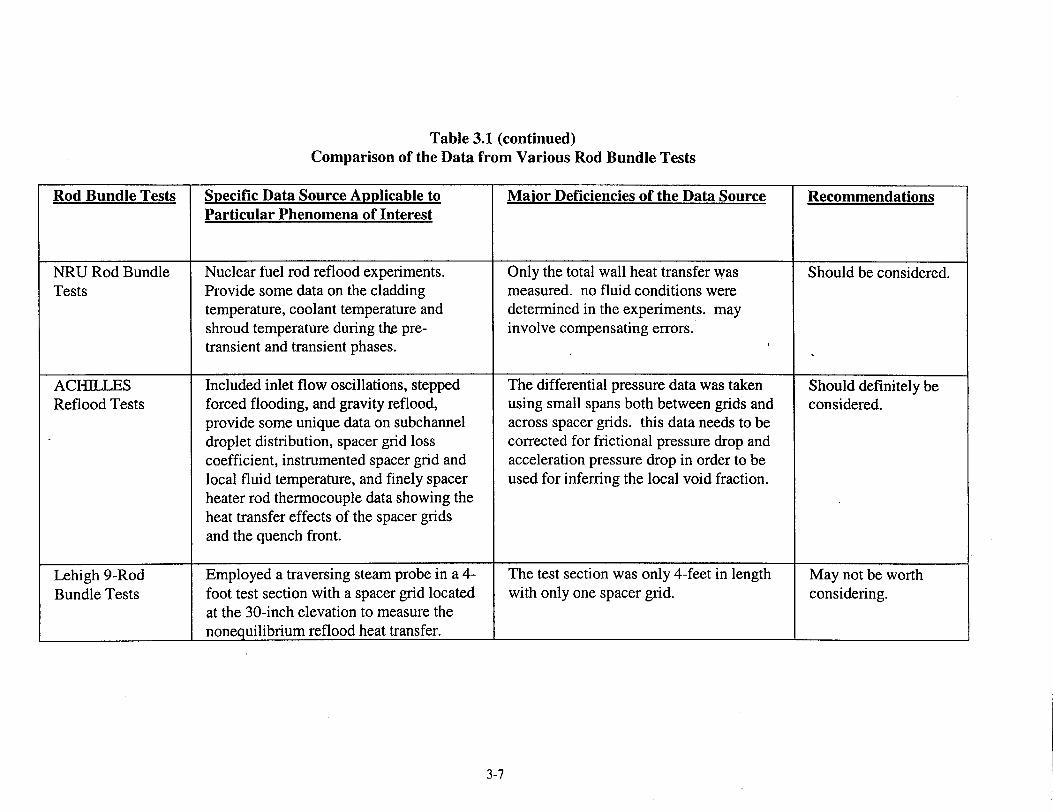
Table 3.1 (continued) Comparison of the Data from Various Rod Bundle Tests
Rod Bundle Tests Specific Data Source Applicable to Major Deficiencies of the Data Source Recommendations Particular Phenomena of Interest
NRU Rod Bundle Nuclear fuel rod reflood experiments. Only the total wall heat transfer was Should be considered. Tests Provide some data on the cladding measured. no fluid conditions were
temperature, coolant temperature and determined in the experiments. may shroud temperature during the pre- involve compensating errors. transient and transient phases.
ACHIL]LES Included inlet flow oscillations, stepped The differential pressure data was taken Should definitely be Reflood Tests forced flooding, and gravity reflood, using small spans both between grids and considered.
provide some unique data on subchannel across spacer grids. this data needs to be droplet distribution, spacer grid loss corrected for frictional pressure drop and coefficient, instrumented spacer grid and acceleration pressure drop in order to be local fluid temperature, and finely spacer used for inferring the local void fraction. heater rod thermocouple data showing the heat transfer effects of the spacer grids and the quench front.
Lehigh 9-Rod Employed a traversing steam probe in a 4- The test section was only 4-feet in length May not be worth Bundle Tests foot test section with a spacer grid located with only one spacer grid. considering.
at the 30-inch elevation to measure the I nonequilibrium reflood heat transfer.
3-7

3.3 Single-Tube Tests and Related Studies
3.3.1 Liquid Entrainment and Breakup
The physical mechanisms that lend to liquid entrainment and breakup are of paramount
importance in that they affect the drop size distribution and the number density. These two
quantities together with the droplet velocity determine the interfacial surface area and interfacial
heat transport. In addition to the interfacial surface area, the presence of droplets in the vapor
flow directly influences the convective heat transfer by modifying the turbulence structure in the
flow field, by evaporation of the droplets, and by direct contact heat transfer at the wall. In fact,
liquid entrainment from the froth region just above the quench front is the single largest
uncertainty in predicting the DFFB behavior in reflooding the rod bundle.
This section focuses on the topic of liquid entrainment and breakup. The topics of drop
size distribution and number density will be discussed in 3.3.2, droplet velocity, drag, and
interactions in 3.3.3, droplet-enhanced heat transfer in 3.3.4, droplet evaporative heat transfer in
3.3.5, and direct contact heat transfer in 3.3.6. In addition, total wall heat transfer will be
discussed in 3.3.7, effects of spacer grids in 3.3.8, the effects of inlet flow oscillation and
nonequilibrium in 3.3.9, and other factors in 3.3.10.
The subject of liquid entrainment and breakup has been studied by Adams and Clare [1,
2], Almenas and Lee [6], Binder and Hanratty [22], Clare and Fairbain [46-48], Cousins and
Hewitt [52], Dallman et al. [55, 56], El Kassaby and Ganic [72], Faeth [79], Ganic et al. [83, 85],
Hanratty and Engen [98], Hay et al. [106], Hewitt [108], Hughmark [116], Hutchinson [117],
Ishii [130], Ishii and Grolmes [131], Ishii and Mishima [125, 126], Jensen [132], Kataoka et al.
[139], Kline et al. [154], Kocamustafaogullari [155], Krzeczkowski [157], Kuo and Cheung
[158], Kutateladze [159], Lee and Ryley [163], Levy [175, 176], Lindsted et al. [177], Lopes and
Dukler [180-182], Lopez de Bertodano and Jan [183], Mastanajak [187], Minh and Huyghe
[190], Newitt et al. [203], Nigmatulin [206], Paras and Karabelas [219], Petrovichev et al. [223],
Podvysotsky and Shrayber [226], Ramirez [228], Richter [233], Sarjeant [235], Schadel et al.
[238], Sekoguchi and Takeishi [242], Smith [247], Soliman and Sims [249], Sugawara [256],
Van der Molen [278], Wicks and Dukler [288], Wilkes et al. [290], Williams et al. [294],
Woodmansee and Hanratty [297], Yadigaroglu [301], Yao [304, 305, 308], Yoshioka and
Hasegawa [315] and Zuber [321].
Depending on the flow situation, entrainment may take place in a number of different
ways. Physically, when two fluids flow over each other, the interface of the two fluids is
inherently unstable. As the relative velocity between the two fluids exceeds a certain critical
value, instabilities set in and grow in the interfacial region, resulting in the formation of wavy
interface and large amplitude roll waves (Hanratty and Hershmen [97] and Ishii and Grohmes
[131]). This so-called Kelvin-Helmholtz instability is responsible for the entrainment of liquid
droplets from a wavy film into a gas flow. Hydrodynamic and surface tension forces govern the
motion and deformation of the wave crests. Under certain conditions, these forces lead to
3-8

extreme deformation of the interface resulting in the breakup of a portion of the wave into several fluid droplets.
The forces acting on the wave crests depend on the flow pattern around them as well as the shape of the interface. In the reflood phase of LOCA, liquid droplets are likely to be generated by shearing off of roll waves. The drag force acting on the wave tops deforms the interface against the retaining force of the liquid surface tension. At vapor velocities beyond the
inception of entrainment, the tops of large amplitude roll waves are sheared off from the wave crests by the vapor flow and then broken into small droplets.
A clear physical understanding of the droplet generation mechanisms is crucial in modeling reflood. The initial sizes and velocities of the droplets depend on how they were generated above the quench front in the froth region. The onset of entrainment is believed to occur when the deforming forces, i.e., the interfacial shear forces or the hydrodynamic drag forces, become greater than the retaining forces, i.e., the surface tension forces [131, 139]. Under some special circumstances, however, large liquid globules can be generated above the quench front by disintegration of waves formed in the wetted position of a flow channel [2].
Inception criteria for the onset of entrainment in annular two-phase flow have been based largely on experimental data, as reported by Ardron and Hall [11], Ishii and Grolmes [131], Jensen [132], Kataoka et al. [139], Kocamustafaogullari et al. [155], Kutateladze [159], Newitt et al. [203], Nigmatulin [206], Richter [233], Sekoguchi and Takeishi [242], Wallis [280], and Zuber [321]. Thus far, no dynamic models have been implemented in existing transient analysis codes to describe the functional dependence of the initial drop sizes and velocities on the droplet generation mechanisms. The key controlling parameters that need to be considered include the film Reynolds number, the viscosity numbers of the fluids, the critical Weber number, the critical mass flux and the Kutateladze number.
The rate of entrainment has been correlated by a number of investigators based upon measured data. Entrainment measurements in annular gas-liquid flow have been interpreted by Dallman et al. [56]. There are two widely used techniques for measuring the fraction of liquid flux that is entrained into the gas phase as droplets. The first is based on local measurements using a sampling probe to determine the liquid mass flux at the axial location of the probe. Usually, measurement is made only along the centerline with the assumption that the mass flux is uniform radially. This technique has been used with limited success [52, 289, 299]. The second technique is based on the measurement of the liquid film flow by removing it from the test section. In so doing, it eliminates those uncertainties associated with the local probe measurement technique. This liquid film removal method is thought to be more accurate [52, 126, 218, 223].
In general, the entrainment rate, which governs the rate of droplet formation, is measured in terms of the so-called entrained fraction. This quantity is defined as the fraction of the liquid flux flowing as droplets in the two-phase flow system. Correlations of the entrainment data have been made by a number of investigators with limited success. The most widely used entrainment correlations include those reported by Dallman et al. [55, 56], Hutchinson and Whalley [117],
3-9
Ishii and Mishima [125], Ishii [130], Minh and Hugghe [190], Nigmatulin [206], Paleev and Filipovich [218], Paras and Karabelas [219], Wicks and Dukler [289], and Williams et al. [294].
An important quantity that needs to be considered along with the rate of liquid entrainment is the rate of deposition of droplets carried by the vapor core to the liquid film. Whereas the entrainment of liquid from the film will cause an increase in the fraction of liquid entrained in the vapor core, the deposition of droplet onto the liquid film will cause a decrease in the fraction of liquid in the vapor core. Although the initial drop sizes and velocities are dictated by the mechanisms of liquid entrainment, the droplet number density and the drop sizes downstream of the point of droplets generation depend on both the rates of entrainment and deposition. Specifically, the rate of deposition has direct influence on the evolution of the liquid droplets in the downstream locations of the vapor core.
The process of droplet deposition has been studied by Almenas and Lee [6], Binder and Hanratty [22], Cousins and Hewitt [52], Dallman and Kirchner [55], El Kassaby and Ganic [72], Ganic et al. [83, 85], Hanratty [99], Hay et al. [106], Langevin [161], Lee and Almenas [164], Lopes and Dukler [182], Mastanajah [187], Nishio and Hirata [208], Paras and Karabelas [219], Pedersen [221], Schadel et al. [238], Sugawara [256], Wilkes et al. [290] and Williams et al. [294]. In general, the rate of deposition of droplets from the vapor core onto the liquid film is a function of the fluid properties, the droplet concentration in the vapor core, and the radial velocities of the droplets. Experimental observations have indicated that the rate of deposition is dependent linearly on the droplet concentration in the vapor core. Useful correlations have been obtained by Binder and Hewitt [22], Nigmatulin [206], Schadel et al. [238], and Williams et al. [294].
3.3.2 Drop Size Distribution and Number Density
The interfacial area and thus the interfacial heat and mass transfer depend not only on the drop size distribution but also on tlae volumetric concentration of the droplets, i.e., the number density. As mentioned in 3.3.1, these two quantities (drop size distribution and number density) are functions of the droplet generation mechanisms and their previous history (i.e., time evolution of the droplets) in the flow field. The latter requires the consideration of droplet entrainment, droplet evaporation, droplet breakup induced by spacer grids, drop coalescence, and droplet deposition upon impingement on the wall. The topics of drop size distribution and number density have been studied extensively by many investigators in the past, notably among which are Adams and Clare [2], Ardron and Hall [11], Claire and Fairbain [46], Coulaloglou and Tavlarides [51], Cousins and Hewitt [52], Cumo et al. [54], De Jarlias [58], Hagiwara et al. [96], Hay et al. [106], Jepson et al. [133], Juhel [135], Kataoka et al. [139], Kocamustafaogullari et al. [155], Kuo and Cheung [158], Lee et al. [165], Mugele and Evans [199], Nukiyama and Tanazawa [212], Podvysotsky and Shrayber [226], Sarjeant [235], Seban et al. [239, 241], Wick and Dukler [289], Wilkes et al. [290], Wong and Hochreiter [295] and Zuber et al. [319, 320].
Owing to the difficulty in defining the drop size distribution, many investigators have characterized the droplets by an average diameter. This simplification, however, can be justified
3-10
only if the axial velocity of the droplets and the droplet concentration are independent of the drop size and do not vary in the radial direction. Whereas the droplet velocities can be assumed independent of the drop size in some cases [11, 290], the droplet concentration cannot be assumed uniform in the radial direction (Zuber et al. [319, 320]. The data of Hagiwara et al. [96]
showed that the droplet concentration decreases from the turbulent core to zero near the wall.
Thus, the use of an average diameter in the expression for the interfacial area is questionable.
Most of the proposed drop size distribution functions are derived from experiments [54, 58, 139, 155, 165, 212, 295]. The maximum drop size is usually calculated using a critical
Weber number. However, the standard droplet disintegration mechanism overestimate the
observed droplet sizes. Most droplets are produced by entrainment at the gas-liquid interface rather than generated during their evolution downstream of the points of entrainment above the quench front. Experimental data indicate that the droplets downstream of the quench front are too small to have been generated by fragmentation, i.e., by the secondary breakup mechanism during their flight as droplets in the gas or vapor flow. In other words, the critical Weber number based upon the relative velocity between the droplets and the gas flow gives rise to much larger
droplet sizes than experimentally observed. Sarjeant [235] found that the breakup time and number of fragments depend on the Weber number. However, the critical Weber number is essentially independent of the droplet Reynolds number. Note that coalescence of droplets may take place immediately downstream of the quench front, owing to the chaotic motion of the droplets. Whereas the secondary breakup due to fragmentation or disintegration would increase
the droplet number density (Juhel [135]), coalescence due to collisions of droplets could increase the Sauter mean diameter (Clare and Fairbaim [46]).
3.3.3 Droplet Velocity, Interfacial Shear, and Interactions
Owing to mechanical non-equilibrium [11, 166], the liquid droplets, once entrained, are accelerated by the aerodynamic drag forces exerted by the vapor flow. Thus, the relative velocity between the liquid and vapor phases may vary continuously in the flow field. Since all the transfer mechanisms at the liquid/vapor interface are affected by the relative velocity, the droplet velocity and interfacial drag as well as droplet-droplet interactions need to be taken into account in modeling the reflood heat transfer. The concentration of the droplets, i.e., the number density, at different elevations above the quench front, depends largely on the velocities of the droplets. The topics of droplet velocity, drag and interaction have been studied by a number of investigators, including Ardron and Hall [11], Brauner and Maron [26], Chuchottaworn and Asano [41], Harmathy [101], Hassan [104, 105], Ishii et al. [127, 128, 129], Kataokaet al. [139], Lee et al. [166-174], Lindsted et al. [177], Nigmatulin and Kukharenko [205], Temkin and Mehta [263], Tsuji et al. [269], Wilkes et al. [290] and Williams and Crane [292].
If the motion of the droplets can be described by a single momentum equation applied to the center of mass of the dispersed phase, i.e., the liquid droplets, the drag force per unit volume can be expressed in terms of the interfacial area concentration, the droplet velocity, and the ratio between the Sauter mean diameter and the mean drag diameter [127]. For spherical particles, the ratio of the Sauter mean diameter and the mean drag diameter is essentially equal to unity regardless of the drop size distribution [139]. For non-spherical particles or distorted droplets,
3-11

the drag force should be better calculated using the drag coefficient. According to Ishii and
Zuber [128], the distorted droplet regime is characterized by the viscosity number.
It should be noted that the drag coefficient calculated by the standard laws does not
account for the effect of mass flux and the droplet-droplet interactions. Chuchottaworn and
Assano [41] calculated the drag coefficient on an evaporating or condensing droplet and found
that the effect of mass flux due to phase change can influence the resulting drag coefficient. The
experimental data of Lee and Durst [166] and Tsuji et al. [269] as well as the analysis of Lee
[168], on the other hand, indicated a significant effect of droplet-droplet interactions on the drag
coefficient. The dependency of the drag coefficient on the Reynolds number is modified
appreciably in the highly dispersed gas-particle viscous regime. For small particles and low
concentrations, the drag coefficient becomes smaller whereas for large particles and high
concentrations, the reverse is found to be the case.
As mentioned above, the droplet motion is usually described by a single momentum
equation for the center of mass of the droplets. This approach requires that the droplet velocities
to be independent of the drop sizes. Since the droplets are accelerated by the vapor flow as soon
as they are generated, one may expect that there are considerable differences in the velocities
among droplets of different sizes. Small droplets, being entrained readily by the vapor flow,
should move faster than large droplets. This expectation, however, may not be the case.
Experimental data for dispersed flow above the quench front [11] and for annular mist flow in
tubes [290] have shown that droplets of various sizes move axially at nearly the same velocity,
close to the terminal velocity of the droplets of average size. This behavior may due in part to
the droplet-droplet interactions and in part to the different radial migration of small and large
droplets. In the former case, momentum exchange during droplet-droplet interactions tends to
render the velocities of the droplets uniform. In the latter case, the small droplets are being slow
down as they are carried by the turbulent eddies toward the wall. On the other hand, the large
droplets, being less affected by turbulent eddies, continue to be accelerated by the vapor flow.
As a result, the droplet velocities may not vary considerably with the droplet sizes.
3.3.4 Droplet-Enhanced Heat Transfer
The presence of liquid droplets in the dispersed flow region has significant effects on the
total heat transfer in the reflood phase. First, the droplets are not at thermal equilibrium with the
vapor flow and there is convective heat transfer between the droplets and the vapor. Second, the
droplet temperatures are different than those of the wall and there is wall to droplet radiation heat
transfer. Third, vaporization of the droplets may take place during their flight and the phase
change process may result in de-superheating of the vapor flow. The rates of convective heat
transfer between the droplets and the vapor, wall to droplet radiation heat transfer and droplet
evaporation depend on the total interfacial area which is a function of the drop size distribution
and number density. Fourth, the liquid droplets may impinge upon the wall which results in
direct contact heat transfer. Fifth, the droplets are hydrodynamically coupled to the vapor flow.
Whereas the droplet motion depends strongly on the flow characteristics of the continuous vapor
phase, the turbulence intensity and transport properties of the vapor flow can be substantially
3-12
modified by the presence of the liquid droplets. In most cases, the liquid droplets may induce higher turbulence in the vapor phase, which would enhance convective heat transfer of the vapor flow at the wall.
The topic of droplet-enhanced heat transfer (i.e., the fifth item mentioned above) has been studied by many investigators, including Aihara [4], Boothroyd and Hague [23], Boothroyd [24], Briller and Peskir [27], Chu [40], Danziger [57], Depew and Kramer [61], Drucker et al. [67], Evans et al. [77], Fabar and Depew [80], Farbar and Morley [81], Hasegawa et al. [103], Holman et al. [114], Kianjah et al. [150], Kiger and Lasheras [151, 152], Koizumi et al. [156], Shrayber [245, 246], Spokoynyy [251], Sukomel et al. [261], Theofanous and Sullivan [264], Tien and Quan [265], Tsuji et al. [269], and Wilkinson and Norman [291]. In most of these studies, solid particles are used to simulate the liquid droplets, excluding the effect of evaporation. The modification of the convective heat transfer coefficient is determined by comparing the case of an upward gas-particle flow to the case of a pure gas flow.
In general, a dispersed phase may alter the convective heat transfer to and from the continuous gas phase in several ways. First, the presence of particles may strongly modify the turbulence structure of the gas phase. Second, the slip between phases may enhance the mixing of the carrier gas. Third, the radial motion of the particles may promote energy exchange between the laminar sublayer and the turbulent core. Fourth, owing to the penetration of the particles in the viscous sublayer, the thickness of the sublayer may be reduced. All these factors tend to flatten the gas velocity profile in the core and reduce the viscous sublayer thickness, resulting in a steeper temperature gradient at the wall and thus a higher rate of convection.
Under certain conditions (large particles at small loading ratios), however, the presence of particles could dampen the eddy motion in the turbulent flow field and may reduce the convective heat transfer due to the transition from turbulent to laminar flow [103, 246]. The key parameter that need to be considered include the loading ratio (i.e., the quality), the particle size, the Reynolds number of the flow, the hydraulic diameter and the wall temperature. Thus far, no correlation is available that properly accounts for the effects of all these parameters.
3.3.5 Droplet Evaporative Heat Transfer
One characteristic feature of dispersed flow is the presence of very high temperature gradients in the continuous vapor phase. Thus, the distribution of the evaporating liquid droplets plays an important role in the heat transfer process. The topic of droplet evaporative heat transfer has been studied by Bellan and Harstad [18], Duncan and Leonard [70], Faeth [79], Gaugler [86], Ghazanfari [87], Harpole [102] Hoffman and Ross [113, 114], Iloeje et al. [123], Kiger and Lasheras [151], Labowsky [160], Lee and Ryley [163], Mostinshiy and Lamden [198], O'Rourke [216], Rane and Yao [231], Sawan and Carbon [237], Toknoka et al. [266], Unal et al. [274, 277], Yamanuchi [302], Yao et al. [308], and Yuen and Chen [317]. Perhaps the most important effects of droplet evaporation are vapor de-superheating near the wall. Droplets can be transported towards the wall by turbulent diffusion. The migration of droplets towards the wall and subsequent evaporation of the droplets greatly reduces the vapor temperature near the wall.
3-13

This vapor de-superheating effect increases the driving temperature difference between the wall
and the vapor and thus enhances the convective heat transfer at the wall. The rate of droplet
migration, however, depends on the radial droplet concentration distribution and the ability of the
droplets to penetrate the viscous sublayer at the wall.
The evaporation of droplets also affects the convective heat transfer from the vapor to the
droplets. In the range of high Reynolds numbers and high evaporation rates, a shielding effect is
observed as a result of droplet evaporation [113, 317]. This shielding effect, caused by the mass
efflux associated with droplet evaporation, reduces convective heat transfer from the superheated
vapor to the liquid droplets. The total evaporation rate for a cloud of droplets can be quite
different than that predicted by the single-drop model [160].
At high droplet concentrations, i.e., for a dense cluster of droplets, there could be an
appreciable reduction of the droplet evaporation rate. This is probably due to the difficulty of the
outer flow to penetrate through the dense cluster. Owing to overlapping boundary layers around
the droplets, the outer flow tends to by pass the cluster of drops. Thus, only those droplets at the
periphery of the cluster are affected by the outer flow. The droplets inside the cluster evaporate
at the rate typical of that for droplet evaporation in a quiescent fluid. This cluster effect of
droplets, however, is somewhat controversial. Bellan and Harstad [18] found that the
evaporation time for a dense cluster of drops is only weakly dependent on the relative velocity
between the cloud of droplets and the vapor flow. On the other hand, Faeth [79] found that for
evaporating sprays, there is very little effect of adjacent droplets on the vaporization rate.
3.3.6 Direct Contact Heat Transfer
The topic of direct contact heat transfer has been investigated by Carbajo and Siegal [30].
Cokmez-Tuzla et al. [50], Dua and Tien [68], Duffey and Porthouse [691, Elias and Yadigaroglu
[74], Groeneveld and Stewart [92], Henry [107], Iloeje et al, [123], Kendall [146], Lin and Yao
[178], Nishio and Hirata [208], Pedersen [221, 222], Piggot et al. [224], Styrikovich et al. [253],
Yao and Cai [303] and Yao and Henry [307]. A comprehensive review of the subject was
recently made by Ayyaswamy [13]. In general, droplet impingement onto the wall is capable of
removing a significant amount of heat from the wall either by direct contact with the hot wall or
by evaporation in the superheated thermal boundary layer at the wall. The latter case results in
de-superheating of the vapor phase and thus increasing the driving temperature difference
between the wall and the vapor, as discussed previously in item V. The former case, i.e., direct
contact heat transfer, is a very effective cooling mechanism and may lead to a significant
enhancement of the heat transfer rate above the quench front. However, direct contact heat
transfer is possible only if the wall is lower than a limiting temperature, i.e., the Leidenfrost
temperature. It is possible, though, to achieve direct liquid-wall contact momentarily on a very
small time scale at higher temperatures [92, 107, 303, 307]. Above the limiting temperature, the
wall is not wettable continuously.
The wettability of a hot wall is an important issue that has been studied by Duffey and
Porthouse [69], Groeneveld and Stewart [92], Iloeje et al. [121-123], Kervinen et al. [147],
3-14
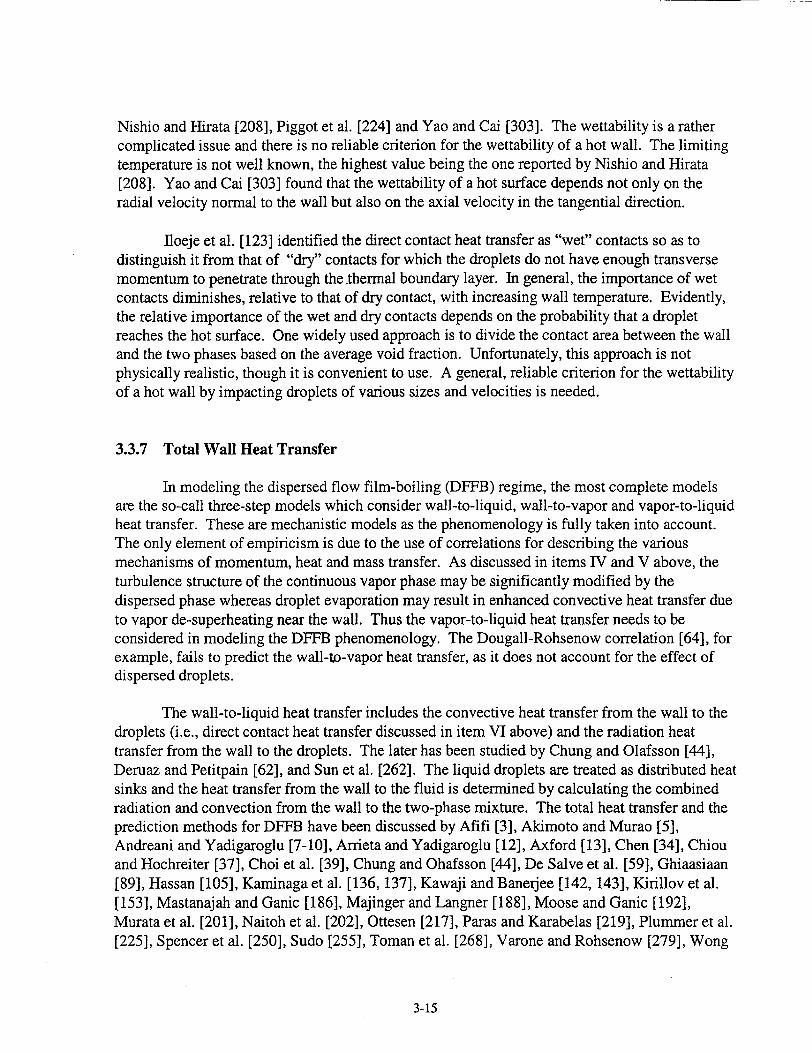
Nishio and Hirata [208], Piggot et al. [224] and Yao and Cai [303]. The wettability is a rather complicated issue and there is no reliable criterion for the wettability of a hot wall. The limiting temperature is not well known, the highest value being the one reported by Nishio and Hirata [208]. Yao and Cai [303] found that the wettability of a hot surface depends not only on the radial velocity normal to the wall but also on the axial velocity in the tangential direction.
floeje et al. [123] identified the direct contact heat transfer as "wet" contacts so as to distinguish it from that of "dry" contacts for which the droplets do not have enough transverse momentum to penetrate through the thermal boundary layer. In general, the importance of wet contacts diminishes, relative to that of dry contact, with increasing wall temperature. Evidently, the relative importance of the wet and dry contacts depends on the probability that a droplet reaches the hot surface. One widely used approach is to divide the contact area between the wall and the two phases based on the average void fraction. Unfortunately, this approach is not physically realistic, though it is convenient to use. A general, reliable criterion for the wettability of a hot wall by impacting droplets of various sizes and velocities is needed.
3.3.7 Total Wall Heat Transfer
In modeling the dispersed flow film-boiling (DFFB) regime, the most complete models are the so-call three-step models which consider wall-to-liquid, wall-to-vapor and vapor-to-liquid heat transfer. These are mechanistic models as the phenomenology is fully taken into account. The only element of empiricism is due to the use of correlations for describing the various mechanisms of momentum, heat and mass transfer. As discussed in items IV and V above, the turbulence structure of the continuous vapor phase may be significantly modified by the dispersed phase whereas droplet evaporation may result in enhanced convective heat transfer due to vapor de-superheating near the wall. Thus the vapor-to-liquid heat transfer needs to be considered in modeling the DFFB phenomenology. The Dougall-Rohsenow correlation [64], for example, fails to predict the wall-to-vapor heat transfer, as it does not account for the effect of dispersed droplets.
The wall-to-liquid heat transfer includes the convective heat transfer from the wall to the droplets (i.e., direct contact heat transfer discussed in item VI above) and the radiation heat transfer from the wall to the droplets. The later has been studied by Chung and Olafsson [441, Deruaz and Petitpain [62], and Sun et al. [262]. The liquid droplets are treated as distributed heat sinks and the heat transfer from the wall to the fluid is determined by calculating the combined radiation and convection from the wall to the two-phase mixture. The total heat transfer and the prediction methods for DFFB have been discussed by Afifi [3], Akimoto and Murao [5], Andreani and Yadigaroglu [7-10], Arrieta and Yadigaroglu [12], Axford [13], Chen [34], Chiou and Hochreiter [37], Choi et al. [39], Chung and Ohafsson [44], De Salve et al. [59], Ghiaasiaan [89], Hassan [105], Kaminaga et al. [136, 137], Kawaji and Banerjee [142, 143], Kirillov et al. [153], Mastanajah and Ganic [186], Majinger and Langner [188], Moose and Ganic [192], Murata et al. [201], Naitoh et al. [202], Ottesen [217], Paras and Karabelas [219], Plummer et al. [225], Spencer et al. [250], Sudo [255], Toman et al. [268], Varone and Rohsenow [279], Wong
3-15
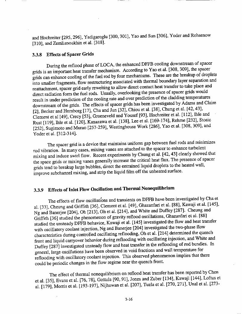
and Hochreiter [295, 296], Yadigaroglu [300, 301], Yao and Sun [306], Yoder and Rohsenow
[310], and Zemlianoukhin et al. [318].
3.3.8 Effects of Spacer Grids
During the reflood phase of LOCA, the enhanced DFFB cooling downstream of spacer
grids is an important heat transfer mechanism. According to Yao et al. [308, 309], the spacer
grids can enhance cooling of the fuel rod by four mechanisms. These are the breakup of droplets
into smaller fragments, flow restructuring associated with thermal boundary layer separation and
reattachment, spacer grid early reweiting to allow direct contact heat transfer to take place and
direct radiation form the fuel rods. Usually, overlooking the presence of spacer grids would
result in under prediction of the cooling rate and over prediction of the cladding temperatures
downstream of the grids. The effects of spacer grids has been investigated by Adams and Claire
[2], Becker and Hernborg [17], Cha and Jun [32], Chiou et al. [38], Chung et al. [42, 43],
Clement et al[49], Crecy [53], Groeneveld and Yousef [93], Hochreiter et al. [112], Ihle and
Rust [119], Ihle et al. [120], Kanazawa et al. [138], Lee et al. [169-174], Rehme [232], Stosic
[252], Sugimoto and Murao [257-2591, Westinghouse Work [286], Yao et al. [308, 309], and
Yoder et al. [312-314].
The spacer grid is a device that maintains uniform gap between fuel rods and minimizes
rod vibration. In many cases, mixing vanes are attached to the spacer to enhance turbulent
mixing and induce swirl flow. Recent experiments by Chung et al. [42, 43] clearly showed that
the space grids or mixing vanes generally increase the critical heat flux. The presence of spacer
grids tend to breakup large bubbles, direct the entrained liquid droplets to the heated wall,
improve subchannel mixing, and strip the liquid film off the unheated surface.
3.3.9 Effects of Inlet Flow Oscillation and Thermal Nonequilibrium
The effects of flow oscillations and transients on DFFB have been investigated by Cha et
al. [33], Cheung and Griffith [36], Clement et al. [49], Ghazanfari et al. [88], Kawaji et al. [145],
Ng and Banerjee [204], Oh [213], Oh et al. [214], and White and Duffey [287]. Cheung and
Griffith [36] studied the phenomenon of gravity reflood oscillations, Ghazanfari et al. [88]
studied the unsteady DFFB behavior, Kawaji et al. [145] investigated the flow and heat transfer
with oscillatory coolant injection, Ng and Banerjee [204] investigated the two-phase flow
characteristics during controlled oscillating reflooding, Oh et al. [214] determined the quench
front and liquid carryover behavior during reflooding with oscillating injection, and White and
Duffey [287] investigated unsteady flow and heat transfer in the reflooding of rod bundles. In
general, large oscillations have been observed in void fractions and wall temperature for
reflooding with oscillatory coolant injection. This observed phenomenon implies that there
could be periodic changes in the flow regime near the quench front.
The effect of thermal nonequilibrium on reflood heat transfer has been reported by Chen
et al. [35], Evans et al. [76, 78], Gottula [90, 91], Jones and Zuber [134], Kawaji [144], Loftus et
al. [179], Morris et al. [193-197], Nijhawan et al. [207], Tuzla et al. [270, 271], Unal et al. [273-
3-16

275], Webb and Chen [281-283], and Williams [293]. Experimental evidence has indicated that significant thermal nonequilibrium can be present in DFFB with vapor superheats of several hundred degrees.
3.3.10 Other Factors
The phenomena of quench front propagation and quench time have been studied by Afifi [3], Barnea and Elias [15], Chung et al. [45], De Salve et al. [59], Dhir and Catton [63], Era et al.
[75], Juhel [135], Seban et al. [241],Ueda et al. [272], Webb and Chen [283], and Yu and Yadigaroglu [316]. The regime of film boiling during reflood has been described by Berenson [21], Hsu [115], Styrikovich et al. [254], Sudo [255], and Weisman [285], whereas the regime of
subcooled boiling has been reported by Dowlati et al. [65], Maitra and Subba-Raju [184], Murao and Sugimoto [200], Savage et al. [236], and Shoukri et al. [244].
The subject of void distribution measurement and prediction has been discussed by Banerjee et al. [14], De Young et al. [60], Dowlati et al. [65], Maitra and Subba-Raju [184], Savage et al. [236], and Zuber and Findlay [319]. The subject of post-dryout heat transfer has
been studied by Bamea [16], Chen et al. [34, 35], Evans et al. [76, 78], Gottula et al. [91], Hochreiter et al. [109-111], Ishii and De Jarlais [124], Ishii and Mishima [125], Jones and Zuber
[134], Kendall [146], Mayinger and Langner [188], Obot and Ishii [215], Plummer et al. [225], Stosic [252], and Unal et al. [274, 276].
The issue of simulating a nuclear fuel pin by an electrically heated rod has been addressed by Broughton et al. [28], Carajilescov [29], Casal et al. [31], Malang and Rust [185], McPherson and Tolman [189], Raepple et al. [227], Soda [248], Sugimoto et al. [260], and Tolman and Gottula [267]. Evaluation of heater rod properties, clad swelling, and rupture behavior has been performed by Hanson [100], Larson [162], Mohr and Hesson [191], Nithianandan et al. [209211], and Sugimoto et al. [260].
The heat transfer rate for single phase and two phase flows in tubes or around bundles have been discussed by Bennett et al. [19], Benodekar and Date [20], Drucker and Dhir [66], Dwyer and Berry [71], El-Genk et al. [73], Forslund and Rohsenow [82], and Groeneveld [94, 95], Hynek at al. [118], Kianjah [148-150], Ramm and Johannsen [229] and Rane and Yao [230].
Finally, phenomena identification and ranking table (PIRT) has been developed for thermal-hydraulic phenomena during large break LOCA by a number of researchers such as Boyack [25], Rohatgi et al. [234], Shaw et al. [243], and Wulff [298]. The RBHT PIRT presented in section 2 of this report was developed specifically for thermal-hydraulic phenomena during the reflood stage of a large break LOCA. The table is most up to date and is most appropriate for reflood heat transfer studies.
3-17
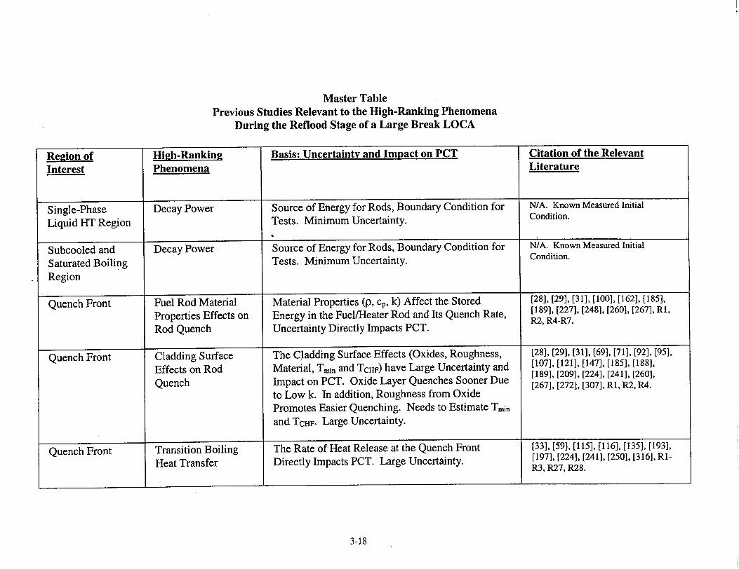
Master Table Previous Studies Relevant to the High-Ranking Phenomena
During the Reflood Stage of a Large Break LOCA
Re2ion of Hi,!h-Rankin2 Basis: Uncertainty and Impact on PCT Citation of the Relevant
Interest Phenomena Literature
Single-Phase Decay Power Source of Energy for Rods, Boundary Condition for N/A. Known Measured Initial
Liquid HT Region Tests. Minimum Uncertainty. Condition.
Subcooled and Decay Power Source of Energy for Rods, Boundary Condition for N/A. Known Measured Initial
Saturated Boiling Tests. Minimum Uncertainty. Condition.
Region
Quench Front Fuel Rod Material Material Properties (p, cp, k) Affect the Stored [28], [29], [31], [100], [162], [185],
Properties Effects on Energy in the Fuel/Heater Rod and Its Quench Rate, [189], [227], [248], [260], [267], R1,
Rod Quench Uncertainty Directly Impacts PCT. R2, R4-R7.
Quench Front Cladding Surface The Cladding Surface Effects (Oxides, Roughness, [28], [29], [31], [69], [71], [92], [95],
Effects on Rod Material, Train and TCHF) have Large Uncertainty and [107], [121], [147], [185], [1881, [189], [209], [224], [241], [260],
Quench Impact on PCT. Oxide Layer Quenches Sooner Due [267], [272], [307], RI, R2, R4.
to Low k. In addition, Roughness from Oxide
Promotes Easier Quenching. Needs to Estimate Tmi and TCHF. Large Uncertainty.
Quench Front Transition Boiling The Rate of Heat Release at the Quench Front [33], [59], [115], [116], [135], [193],
Heat Transfer Directly Impacts PCT. Large Uncertainty. [197], [224], [241], [250], [316], RIR3, R27, R28.
3-18
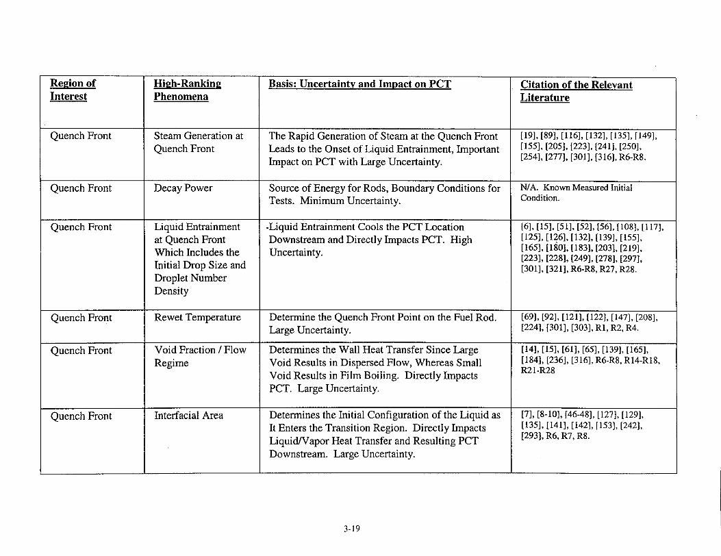
Region of High-Ranking Basis: Uncertainty and Impact on PCT Citation of the Relevant Interest Phenomena Literature
Quench Front Steam Generation at The Rapid Generation of Steam at the Quench Front [19], [89], [116], [132], [135], [149], Quench Front Leads to the Onset of Liquid Entrainment, Important [155], [205], [223], [241], [250],
Impact on PCT with Large Uncertainty. [254], [277], [301], [316], R6-R8.
Quench Front Decay Power Source of Energy for Rods, Boundary Conditions for N/A. Known Measured Initial Tests. Minimum Uncertainty. Condition.
Quench Front Liquid Entrainment -Liquid Entrainment Cools the PCT Location [6], [15], [51], [52], [56], [108], [117], at Quench Front Downstream and Directly Impacts PCT. High [125], [126], [132], [139], [155], Which Includes the Uncertainty. [165], [180], [183], [203], [219],
[223], [228], [249], [278], [297], Initial Drop Size and [301], [321], R6-R8, R27, R28. Droplet Number Density
Quench Front Rewet Temperature Determine the Quench Front Point on the Fuel Rod. [69], [92], [121], [122], [147], [208], Large Uncertainty. [224], [301], [303], R1, R2, R4.
Quench Front Void Fraction / Flow Determines the Wall Heat Transfer Since Large [14], [15], [61], [65], [139], [165], Regime Void Results in Dispersed Flow, Whereas Small [184], [236], [316], R6-R8, R14-R18,
Void Results in Film Boiling. Directly Impacts R21-R28
PCT. Large Uncertainty.
Quench Front Interfacial Area Determines the Initial Configuration of the Liquid as [7], [8-10], [46-48], [127], [129], It Enters the Transition Region. Directly Impacts [135], [141], [142], [153], [242],
Liquid/Vapor Heat Transfer and Resulting PCT [293], R6, R7, R8.
Downstream. Large Uncertainty.
3-19
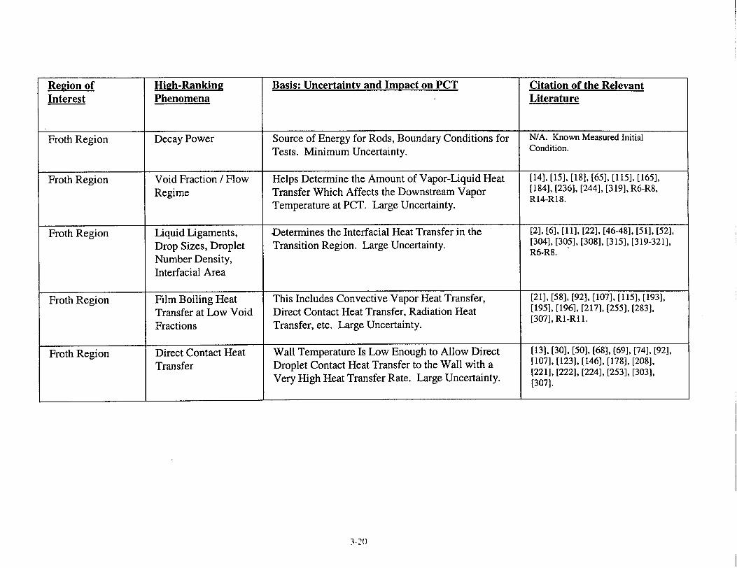
Region of High-Ranking Basis: Uncertainty and Impact on PCT Citation of the Relevant Interest Phenomena Literature
Froth Region Decay Power Source of Energy for Rods, Boundary Conditions for N/A. Known Measured Initial
Tests. Minimum Uncertainty. Condition.
Froth Region Void Fraction / Flow Helps Determine the Amount of Vapor-Liquid Heat [141, [15], [18], [65], [115], [165],
Regime Transfer Which Affects the Downstream Vapor [184), [236], [244], [319], R6-R8,
Temperature at PCT. Large Uncertainty. R14-R18.
Froth Region Liquid Ligaments, Determines the Interfacial Heat Transfer in the [21, [6], [11], [22], [46-48], [51], [52],
Drop Sizes, Droplet Transition Region. Large Uncertainty. [304], [305], [308], [3151, [319-321],
Number Density, R6-R8.
Interfacial Area
Froth Region Film Boiling Heat This Includes Convective Vapor Heat Transfer, [21], [58], [92], [107], [115], [193],
Transfer at Low Void Direct Contact Heat Transfer, Radiation Heat [1951, [1961, [2171, [255], [283],
Fractions Transfer, etc. Large Uncertainty. [307], Ri-Ri 1.
Froth Region Direct Contact Heat Wall Temperature Is Low Enough to Allow Direct [13], [30], [50], [68], [69], [74], [92], Transfer Droplet Contact Heat Transfer to the Wall with a [107], [123], [146], [178], [208], [221], [222], [224], [253], [303],
Very High Heat Transfer Rate. Large Uncertainty. [307].
3-20

Re2ion of Hi2h-Ranking Basis: Uncertainty and Impact on PCT Citation of the Relevant Interest Phenomena Literature
DFFB Region Decay Power Source of Energy for Rods, Boundary Conditions for N/A. Known Measured Initial Tests. Minimum Uncertainty. Condition.
DFFB Region Dispersed Flow Film Directly Impacts PCT, High Uncertainty in [3], [5], [7-10], [12], [34], [37], [39], Boiling Modeling. [44], [59], [89], [105], [109-111], [136], [137], [142], [143], [153], [186], [188], [192], [201], [202], [217], [219], [225], [250], [255], [268], [279], [295], [296], [300], [301], [306], [310], [318], R1-R13, R19-R26.
DFFB Region Convection to Principal Mode of Heat Transfer, Directly Impacts [8-10], [19], [66], [77], [82], [89], Superheated Vapor PCT. Large Uncertainty. [94], [105], [118], [136], [137], [143145], [148], [149], [153], [186], [192], [201], [207], [230], [250], [268], [295], [296], [300], [306], [310], R1R8, R12, R13.
DFFB Region Drop Sizes, Droplet Determines the Interfacial Heat Transfer in the [54-56], [58], [72], [79], [83], [85], Number Density, DFFB Region. Large Uncertainty. [96], [98], [106], [108], [116], [117], Interfacial Area [125], [130], [131], [133], [135], [139], [154], [155], [157-159], [163], [165], [175-177], [180-183], [187], [190], [199], [203], [206], [212], [219], [223], [226], [228], [233], [235], [238], [239], [241], [242], [247], [249], [256], [278], [288-290], [293-295], [297], [301]
3-21

Region of High-Rankin2 Basis: Uncertainty and Impact on PCT Citation of the Relevant Interest Phenomena Literature
DFFB Region Dispersed Phase Important Impact on PCT as the Enhancement Can [4], [23], [24], [27], [40], [57], [61], Enhancement of Be Over 50% in Some Cases. Large Uncertainty. [67], [77], [80], [81], [103], [114], Convective Heat [150-152], [156], [245], [246], [251],
[261], [264], [265], [269], [291], R1,
Transfer R2, R4.
DFFB Region Droplet to Vapor The Interfacial Heat Transfer Reduces the Vapor [18], [70], [79], [86], [87], [102], Interfacial Heat Temperature (i.e., De-superheat) Which Is the Heat [113], [114], [123], [151], [160], Transfer Sink for the Wall Heat Flux. Large Uncertainty. [[163], [198], [216], [231], [237],
[2,66], [274], [277], [302], [308],
[317], R1;R2, R5-R8, R21, R23-R26.
DFFB Region Radiation Heat Very Important at High Bundle Elevations Where [37], [44], [62], [89], [102], [109-111], Transfer Between the Convective Heat Transfer Is Small Due to Large [137], [188], [192], [251], [261],
Surfaces, Vapor, and Vapor Superheat. Very Important for BWR Reflood [262], R1-R8, R13, R19, R20, R25.
Droplets with Sprays and Cold Surrounding Surfaces. Large Uncertainty.
DFFB Region Interfacial Shear and Effects the Void Fraction Distribution and Resulting [11], [26], [41], [101], [104], [105], Droplet Velocity Droplet Velocity in the Entrained Flow. Large [127-129], [139], [166-174], [177],
Uncertainty. [205], [263], [269], [290], [292], R6R8.
3-22
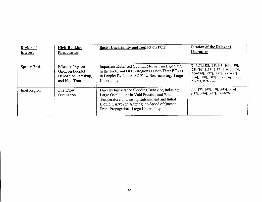
3-23
Region of High-Ranking Basis: Uncertainty and Impact on PCT Citation of the Relevant
Interest Phenomena Literature
Spacer Grids Effects of Spacer Important Enhanced Cooling Mechanism Especially [2], [17], [32], [38], [42], [43], [49],
Grids on Droplet in the Froth and DFFB Regions Due to Their Effects [53], [93], [112], [119], [120], [138], [166-174], [232], [252], [257-259],
Deposition, Breakup, in Droplet Evolution and Flow Restructuring. Large [286], [308], [309], [3 12-314], R6-R8,
and Heat Transfer Uncertainty. R9-R11, R21-R26.
Inlet Region Inlet Flow Directly Impacts the Flooding Behavior, Inducing [33], [36], [49], [88], [145], [204],
Oscillation Large Oscillations in Void Fraction and Wall [213], [214], [287], R21-R26.
Temperature, Increasing Entrainment and Initial Liquid Carryover, Altering the Speed of Quench Front Propagation. Large Uncertainty.
3.4 Master Table: Previous Studies Relevant to the High-Ranking Phenomena Identified in the PIRT for the RBHT Program
Based on the PIRT for the RBHT program described in section 2.0 and the results of the literature review presented in sections 3.2 and 3.3, a master table is developed which summarizes all the previous studies relevant to the highly ranked phenomena during the reflood stage of a large break LOCA. The master table identifies the data source listed in section 3.5 that may be useful for addressing each type of phenomena taking place in various regions of the rod bundle during the reflood stage.
From the literature survey as highlighted in the master table, it was found that there are large differences between the data obtained from the rod bundle tests and those from the single tube tests. The RBHT test facility is designed specifically to address this data deficiency. The RBHT program will aim at obtaining not only wall-to-fluid heat transfer correlations but also models for interfacial heat transfer. To develop and assess models for interfacial phenomena with the goal of significantly improved accuracy and to minimize the potential for compensating errors will require a new or improved database that includes more detailed information than is currently available. The specific needs for new or improved data are described below.
1. In dispersed flow film boiling, the primary heat transfer mechanism is convective heat transfer to superheated steam. It is now recognized that the steam heat transfer coefficient can be enhanced by up to 100% due to the presence of entrained droplets. No suitable models currently exist for this phenomenon. The combination of single-phase convection experiments and twophase convection experiments with droplet injections (with known drop sizes and flow rates) to be performed in the RBHT test facility will provide important new data and result in the development of the needed model.
2. Once the uncertainty involving droplet-enhanced heat transfer is resolved, there still remains the difficulty in predicting the heat transfer rate for the dispersed flow film-boiling (DFFB) regime due to the difficulty in calculating the steam superheat. The amount of steam superheat is governed by the interfacial heat transfer between the steam and the evaporating droplets. To correctly calculate the interfacial heat transfer requires the knowledge of both the entrained drop size and the droplet flow rate. There is very little data of this type currently available for quenching rod bundles. The RBHT program will generate the needed database through advanced instrumentation involving the use of a laser illuminated digital camera system to determine the entrained drop size and measure the droplet flow rate.
3. Although data showing the effects of spacer grids is available, the phenomenon is still not completely understood. In particular, the separate-effects of spacer grids for interfacial shear in rod bundles at low pressures, in dispersed flow film boiling, and in transition boiling heat transfer during reflood, are not known. It is necessary to determine the grid geometry effects. The RBHT program, which will explore two or more types of space grids and will perform heat transfer measurements in various flow regions at locations just before and after the spacer grids, will greatly augment the database needed for modeling the spacer grid effects.
3-24

4. There is insufficient data on transition boiling heat transfer during quenching in rod bundles. This is especially true regarding the minimum film boiling temperature. For reflood conditions where precursory cooling is important, the transition regime is responsible for the final quench and most likely controls the quench front propagation. The emphasis of the RBHT program to measure the local values of the void fraction in the quench front region will provide the much-needed database.
5. When the flow at the quench front is subcooled, an inverted annular film boiling (IAFB) regime would develop immediately downstream of the quench front. The liquid-rich region provides the precursory cooling that controls the quench front velocity and provides the source of vapor and entrained liquid for the DFFB region. It has been demonstrated that many of the apparent functional dependencies for the IAFB regime are primarily due to the axial profile of the void fraction in this region. Currently available data for this regime in rod bundles is insufficient for model development due to the coarse spacing used for the void fraction measurements. The RBHT program will address this data need through the use of finely spaced delta-P cells and by a local void fraction measurement provided by a low energy gammadensitometer.
6. The heat transfer rate in the IAFB region increases rapidly with liquid subcooling. Higher subcooling promotes heat transfer to the liquid core and reduces vapor generation and the thickness of the vapor film, thus enhancing heat transfer. It is traditional to formulate reflood test matrices by fixing the inlet subcooling and then varying the inlet flow rate. This procedure does not provide a true single parameter variation needed for model development at the subcomponent levels. In the RBHT program, non-traditional procedures involving fixing either the local subcooling or the mass flux at constant values at the quench front will be done by choosing appropriate combinations of the inlet flow rate and subcooling in the planned experiments. This will provide important new data not available heretofore.
7. The database in the nucleate boiling regime for void fraction (i.e., interfacial shear) in rod bundles at low-pressure conditions has been identified as a code deficiency during the AP600 code applicability program. Some data exists or can be backed out of other reflood test data after the bundle has quenched. The RBHT can be conveniently used to generate, for negligible additional costs, a comprehensive database with systematic variation of parameters that would greatly aid model development and assessment.
The various technical issues discussed above provide clear justifications for the need for developing the Rod Bundle Heat Transfer Facility. Separate-effects tests will be performed in this facility to obtain new or improved data for model development and code validation at the most fundamental subcomponent levels.
3-25

3.5 References
3.5.1 Single Tube Tests and Related Studies
1. Adams, J. E. and A. J. Clare, "A Preliminary Study of Droplet Breakup at PWR Spacer Grids," PWR/HTWG/P 130, 1983.
2. Adams, J. E. and A. J. Clare, "Droplet Break-up and Entrainment at P.W.R. Spacer Grids," First Int. Workshop on Fundamental Aspects of Post-Dryout Heat Transfer, Salt Lake City, Utah, NUREG/CP-0060, April 2-4, 1984.
3. Afifi, J., "Evaluation of Some Large "Best Estimate" Computer Codes for the Prediction of Loss of Coolant Accidents in Light Water Reactors," Ph.D. Thesis, University of London, 1985.
4. Aihara, T., "Augmentation of Convective Heat Transfer by Gas-Liquid Mist," CONF900803, PP. 445-462, 1990.
5. Akimoto, H. and Y. Murao, "Current Experiment Status and Future Plan for Reflood Tests at Japan Atomic Energy Research Institute," paper presented at ICAP Post-CHF Meeting, Winfrith, England, June 22-25, 1987.
6. Almenas, K. and R. Lee, "Droplet Deposition Above a Quench Front During Reflood," Trans. American Nuclear Society, Vol. 43, PP. 787-788, 1982.
7. Andreani, M. and G. Yadigaroglu, "A Mechanistic Eulerian-Lagrangian Model for Dispersed Flow Film Boiling," CONF-900531 1, PP. 423-432, 1991.
8. Andreani, M. and G. Yadigaroglu, "Difficulties in Modeling Dispersed-Flow Film Boiling," Waeme- und Stoffuebertragung (Germany), Vol. 27:1, PP. 37-49, Oct. 1991.
9. Andreani, M. and G. Yadigaroglu, "Dispersed Flow Film Boiling: An Investigation of the Possibility to Improve the Models Implemented in the NRC Computer Codes for the Reflood Phase for the LOCA," NUREG/IA-0042, Aug. 1992.
10. Andreani, M. and G. Yadigaroglu, "Prediction Methods for Dispersed Flow Film Boiling," Int. Journal Multiphase Flow, Vol. 20, PP. 1-51, 1994.
11. Ardron, K. A. and P. C. Hall, "Droplet Hydrodynamics and Heat Transfer in the Dispersed Flow Regime in Bottom Flooding," CEGB, RD/B/5007N81, University of California at Berkeley, 1981.
12. Arrieta, L. and G. Yadigaroglu, "An Analytical Model for Bottom Reflooding Heat Transfer in Light Water Reactors (UNFLOOD Code)," EPRI-NP-756, 1978.
13. Ayyaswamy, P. S., "Direct-Contact Transfer Precesses with Moving Liquid Droplets," Advances in Heat Transfer, Vol. 26, PP. 1-105, 1995.
3-26

14. Banerjee, S., P. Yeun, and M. A. Vanderbroek, "Calibration of Fast Neutron Scattering Technique for Measurement of Void Fraction in Rod Bundles," J. Heat Transfer, Vol. 101, May 1979.
15. Bamea, Y. and E. Elias, "Flow and Heat Transfer Regimes During Quenching of Hot Surfaces," Int. Journal Heat Mass Transfer, Vol. 37, PP. 1441-1453, 1994.
16. Barzoni, G., "A Study on Postdryout Heat Transfer for Conditions of Interest in Loss of Coolant Accident Ananysis," CISE-1616, P. 31, 1980.
17. Becker, K. H., and C. M. Hernborg, "Measurements of the Effects of Spacers on the Burnout Conditions for Flow Boiling Water in a Vertical Annulus and a Vertical 7-Rod Cluster," AE-165, 1964.
18. Bellan, J. and K. Harstad, "Analysis of the Convective Evaporation of Nondilute Clusters of Drops," Int. Journal Heat Mass Transfer, Vol. 30, No. 1, PP. 125-136, 1987.
19. Bennett, A. W., G. F. Hewitt, H. A. Kearsey and R. F. K. Keeys, "Heat Transfer to
Steam-Water Mixtures Flowing in Uniformly Heated Tubes in Which the Critical Heat Flux Has Been Exceeded," AERE-R-5373, 1967.
20. Benodekar, R. W., and A. W. Date, "Numerical Prediction of Heat-Transfer Characteristics of Fully Developed Laminar Flow Through a Circular Channel Containing Rod Clusters," Int. Journal Heat Mass Transfer, Vol. 21, PP. 935-945, 1978.
21. Berenson, P. J., "Film Boiling Heat Transfer from a Horizontal Surface," Journal Heat
Transfer, Vol. 83, PP. 351-358, 1961.
22. Binder, J. L. and T. J. Hanratty, "A Diffusion Model for Droplet Deposition in GasLiquid Annular Flow," Int. Journal multiphase Flow, Vol. 17, PP. 1-9, 1991.
23. Boothroyd, R. G. and H. Hague, "Fully Developed Heat Transfer to a Gaseous Suspension of Particles Flowing Turbulently in Ducts of Different Size," Journal Mechanical Engineering Science, Vol. 12, No. 3, PP. 191-200, 1970.
24. Boothroyd, R. G., "Similarity in Gas-Born Flowing Particulate Suspensions," ASME
Paper No. 68-MH-11, 1968.
25. Boyack, B., "AP600 Large Break Loss-of-Coolant Accident Phenomena Identification and Ranking Tabulation," LA-UR-95-2718, 1995.
26. Brauner, N. and D. M. Maron, "Dynamic Model for the Interfacial Shear as a Closure Law in Two-Fluid Models," Nuclear Engineering and Design, Vol. 149, PP. 67-79, 1994.
27. Briller, R., and R. L. Peskin, "A Mechanistic Approach to Gas Solid Suspension Heat
Transfer and Friction Factors," Augmentations of Convective Heat & Mass Transfer, ASME, New York, PP. 124-133, 1970.
3-27

28. Broughton, J. M., D. W. Golden, and P. E. MacDonald, "Assessment of Nuclear Fuel
Rod and Solid Electric Heater Thermal Behavior During the Heatup and Reflood Phases
of a Large Break LOCA," CONF-810802-23, P. 12, 1981.
29. Carajilescov, P., "Limits of the Simulation of a Nuclear Fuel Pin by an Electrically
Heated Rod," CONF-921234, P. 3, 1992.
30. Carbajo, J. J., and A. D. Siegei, "A Review and Comparison Among the Different Models
for Rewetting in LWR's," Nucl. Engng. Design, Vol. 58, PP. 33-44, 1980.
31. Casal, V., S. Malang, and K. Rust, "Comparison of Thermal Behavior of Different PWR
Fuel Rod Simulators for LOCA Experiments," KFK-3416-B, P. 2, Oct. 1982.
32. Cha, J. H. and H. G. Jun, "Air-Water Flooding in Multirod Channels: Effects of Spacer
Grids and Blockage," Journal Korean Nucl. Soc., Vol. 30, PP. 381-393, 1993.
33. Cha, Y. S., R. E. Henry, and P. A. Lottes, "An Experimental Investigation of Quench
Front Movement During Bottom Reflood of a Vertical Tube Under Forced-Oscillation
Conditions," ANIJRAS/LWR-80-1, Jan. 1980.
34. Chen, J. C., "A Short Review of Dispersed Flow Heat Transfer in Post-Dryout Boiling,"
Nucl. Engng. Design, Vol. 95, PP. 375-383, 1984.
35. Chen, J. C., F. T. Ozkaynak and R. K. Sundaram, "Vapor Heat Transfer in Post-CHF
Region Including the Effect of Thermodynamic Nonequilibrium," Nucl. Engineering and
Design, Vol. 59, PP. 143-155, 1979.
36. Cheung, Y. L. and P. Griffith, "Gravity Reflood Oscillations in a Pressurized Water
Reactor," NUREG/CR-1314, 1980.
37. Chiou, J. S. and L. E. Hochreiter, "Combined Radiation and Dispersed Flow Film Boiling
in BWR Rod Bundles with Top Spray," Proceedings of the 2 6 h Natl. Heat Transfer
Conference, Philadelphia, PA, Aug. 1989.
38. Chiou, J. S., L. E. Hochreiter, M. J. Lottus, M. Y. Young, J. Chao, C. Chui, "Effects of
Spacer Grids on Thermal Hydraulic Performance During a Postulated Reflood Transient,"
CONF-841075, 1984.
39. Choi, J. H., S. Y. Lee, and S. K. Kim, "Incorporation of Droplet Breakup Model at Spacer
Grid into RELAP/MOD2," J. Korean Nuclear Society, Vol. 22:4, PP. 326-336, Dec.
1990.
40. Chu, N. C., "Turbulent Heat Transfer of Gas-Solid Two-Phase Flow in Circular Tubes,"
Ph.D. Thesis, Department of Mechanical Engineering, University of Washington, 1971.
41. Chuchottaworn, P. and K. Asano, "Calculation of Drag Coefficients on an Evaporating or
Condensing Droplet," Journal of Chem. Engineering of Japan, Vol. 18, PP. 91-94, 1985.
42. Chung, J. B., "An Experimental Study of the Effects of the Mixing Vane of the CHF in the Low-Pressure, Low-Flow Conditions," M.S. Thesis, KAIST, Korea, 1995.
43. Chung, J. B., W. P. Baek and S. H Cheng, "Effects of Spacer and Mixing Vanes on Critical Heat Flux for Low-Pressure Water at Low-Velocities," Int. Comm. Heat Mass Transfer, Vol. 23, PP. 757-765, 1996.
44. Chung, J. N. and S. I. Olafsson, "Two-Phase Droplet Flow Convective and Radiative Heat Transfer," Int. Journal Heat Mass Transfer, Vol. 27, No. 6, PP. 901-910, 1984.
45. Chung, M. K., S. H. Lee, C. K. Park, and Y. W. Lee, "Reflood Experiments with Horizontal and Vertical Flow Channels," Journal Korean Nucl. Soc., Vol. 12, PP. 153162, 1980.
46. Clare, A. J. and S. A. Fairbairn, "Droplet Dynamics and Heat Transfer in Dispersed TwoPhase Flow," The First Int. Workshop on Fundamental Aspects of Post-Dryout Heat Transfer, Salt Lake City, Utah, NUREG/CP-0060, April 2-4, 1984.
47. Clare, A. J., S. A. Fairbairn, and H. C. Simpson, "Droplet Dynamics and Heat Transfer in Dispersed Two-Phase Flow," CONF-840709, PP. 49-71, 1984.
48. Clare, A. J., S. A. Fairbaim, E. Skupinski, B. Tolley, and J. Vilain, "Droplet Dynamics and Heat Transfer in Dispersed Two-Phase Flow," CONF-8410331, PP. 51-62, 1985.
49. Clement, P., R. Deruazz, and J. M. Viteau, "Reflooding of a PWR Bundle Effect of Inlet Flow Rate Oscillations and Spacer Grids," Jun. 1982.
50. Cokmez-Tuzla, A. F., K. Tuzla, and J. C. Chen, "Experimental Assessment of LiquidWall Contacts in Post-CHF Convective Boiling," Nucl. Engng. Design, Vol. 139, PP. 97103, 1993.
51. Coulaloglou, C. A. and L. L. Tavlarides, "Droplet Size Distribution and Coalescence Frequencies of Liquid-Liquid Dispersions in Flow Vessels," AIChE Journal, Vol. 22, No. 2, PP. 289-296, Mar. 1976.
52. Cousins, L. B. and C. F. Hewitt, "Liquid Phase Mass Transfer in Annular Two-Phase Flow: Droplet Deposition and Liquid Entrainment," UK AEA Report AERE-R5657, 1968.
53. Crecy, F. de., "The Effect of Grid Assembly Mixing Vanes on Critical Heat Flux Values and Azimuthal Location in Fuel Assemblies," Sixth Int. Topical Mtg. Nuclear Reactor Thermal Hydraulics, Grenoble, France, 1993.
54. Cumo, M., G. E. Farello, G. Ferrari and G. Palazzi, "On Two-Phase Highly Dispersed Flows," ASME Paper 73-HT-18, 1973.
55. Dallman, J. C. and W. L. Kirchner, "De-entrainment Phenomena on Vertical Tubes in Droplet Cross Flow," NUREG/CR-1421, April 1980.
3-29

56. Dallman, J. C., B. E. Jones and T. J. Hanratty, "Interpretation of Entrainment Measurements in Annular Gas-Liquid Flow," Two-Phase Momentum Heat Mass Transfer, Vol. 2, PP. 681-705, 1979.
57. Danziger, W. J., "Heat Transfer to Fluidized Gas-Solids Mixtures in Vertical Transport," I&EC Process Design and Development, Vol. 2, No. 4, PP. 269-276, 1963.
58. De Jarlais, G., "An Experimental Study on Inverted Annular Flow Hydrodynamics Utilizing on Adiabatic Simulation," NUREG/CR-3339, 1983.
59. De Salve, M., B. Panella, C. Chin and G. Brown, "Validation of a Bottom Flooding Model," 3 rd Int. Mtg. Nuclear Reactor Thermal Hydraulics, 1985.
60. De Young, T. L. and M. P. Plessinger, "Fist Bundle Void Fractions," Idaho Natl. Engineering Laboratory, Oct. 1986.
61. Depew, C. A., and T. J. Kramer, "Heat Transfer to Flowing Gas-Solid Mixtures," Advances on Heat Transfer, Vol. 9, PP. 113-180, 1973.
62. Deruaz, R. and B. Petitpain, "Modelling of Heat Transfer by Radiation During the Reflooding Phase of LWR," Proc. of the Specialist Meet on the Behavior of the Fuel Elements under Accident Conditions, Spatind, Norway, September 13-16, 1976.
63. Dhir, V. K. and I. Catton, "Reflood Experiments with a 4-Rod Bundle," EPRI-NP-1277, 1979.
64. Dougall, R. L. and W. M. Rohsenow, "Film Boiling on the Inside of Vertical Tubes with Upward Flow of the Fluid at Low Qualities," MIT-TR-9079-26, 1963.
65. Dowlati, R., M. Kawaji, D. Chisholm, and A. Chen, "Void Fraction Predication on TwoPhase Flow Across a Tube Bundle," AIChE Journal, Vol. 38, PP. 619-622, 1992.
66. Drucker, M. and V. K. Dhir, "Studies of Single- and Two-Phase Heat Transfer in a Blocked Four-Rod Bundle," EPRI-NP-3485, Jun. 1984.
67. Drucker, M. I., V. K. Dhir and R. B. Duffey, "Two-Phase Heat Transfer for Flow in Tubes and Over Rod Bundles with Blockages," Journal Heat Transfer, Vol. 106, PP. 856-864, 1984.
68. Dua, S. S., and C. L. Tien, "Two-Dimensional Analysis of Conduction Controlled Rewetting with Precursory Cooling," Journal Heat Transfer, Vol. 98, PP. 407-413, 1976.
69. Duffey, R. B. and D. T. C. Porthouse, "The Physics of Rewetting in Water Reactor Emergency Core Cooling," Nucl. Engng. Design, Vol. 25, PP. 379-394, 1973.
70. Duncan, J. D. and J. E. Leonard, "Heat Transfer in a Simulated BWR Fuel Bundle Cooled by Spray Under Loss of Coolant Conditions," GEAP-13086, Paper 11-2, 1972.
3-30

71. Dwyer, 0. E. and H. C. Berry, "Effects of Cladding Thickness and Thermal Conductivity on Heat Transfer for Laminar In-line Flow Through Rod Bundles," Nuclear Science & Engineering, Vol. 42, PP. 69-80, 1970.
72. El Kassaby, M. M. and E. N. Ganic, "A Further Study in Drop Deposition," Multiphase Flow and Heat Transfer III, Part A, ed. Veziroglu and Bergles, Elsevier Science Publishers B. V., Amsterdam, ,1984.
73. El-Genk, M. S., J. S. Philbin, and F. C. Foushee, "Research Program: The Investigation of Heat Transfer and Fluid Flow at Low Pressure," CONF-8604117-3, 1986.
74. Elias, E. and G. Yadigaroglu, "A General One-Dimensional Model for Conduction Controlled Rewetting of a Surface," Nucl. Engng. Design, Vol. 42, PP. 184-194, 1977.
75. Era, A., G. P. Gaspari, A. Hassid, A. Milani and R. Zavattarelli, "Heat Transfer Data in the Liquid Deficient Region for Steam-Water Mixtures at 70 kg/cm2 Flowing in Tubular and Annular Conduits," CISE-R-184, June 1966.
76. Evans, D. G., S. W. Webb and J. C. Chen, "Measurement of Axially Varying Nonequilibrium in Post-Critical-Heat-Flux Boiling in a Vertical Tube," NUREG/CR-3363, June 1983.
77. Evans, D. G., S. W. Webb, and J. C. Chen, "Axially Varying Superheats in Convective Film Boiling," J. Heat Transfer, Vol. 107, Aug. 1985.
78. Evans, D., "Experimental Data for Nonequilibrium Post-CHF Heat Transfer in a Vertical Tube," Proc. 1 0 h Water Reactor Safety Information Meeting, Vol. 1, PP. 227-231, 1983.
79. Faeth, G. M., "Evaporation and Combustion of Sprays," Prog. Energy Comb. Sci., Vol. 9, PP. 1-76, 1983.
80. Farbar, L. and C. A. Depew, "Heat Transfer Effects to Gas-Solids Mixtures Using Spherical Particles of Uniform Size," Industrial and Engineering ChemistryFundamentals, Vol. 2, No. 2, PP. 130-135, 1963.
81. Farbar, L., and M. J. Morley, "Heat Transfer to Flowing Gas-Solids Mixtures in a Circular Tube," Industrial and Engineering Chemistry, Vol. 49, No. 7, PP. 1143-1150, 1957.
82. Forslund, R. P. and W. M. Rohsenow, "Dispersed Flow Film Boiling," Journal Heat Transfer, Vol. 90, PP. 399-407, 1968.
83. Ganic, E. N. and K. Mastanajah, "Investigation of Droplet Deposition from a Turbulent Gas Stream," Int. Journal Multiphase Flow, Vol. 7, PP. 401-422, 1981.
84. Ganic, E. N. and W. M. Rohsenow, "Dispersed Flow Heat Transfer," Int. Journal Heat Mass Transfer, Vol. 20, PP. 855-866, 1977.
3 31
85. Ganic, E. N. and W. M. Rohsenow, "On the Mechanism of Liquid Drop Deposition in
Two-Phase Dispersed Flow," Journal Heat Transfer, Vol. 101, PP. 288-294, 1979.
86. Gaugler, R. E., "An Experimental Study of Spray Cooling of High Temperature
Surfaces," Dept. of Mech. Eng., Carnegie Inst. Of Tech., Pittsburgh, PA, July 1966.
87. Ghazanfari, A., "Instationary Heat Transfer in a Droplet Flow After Exceeding of the
Wetting Temperature," CONF-780465, PP. 150-153, 1978.
88. Ghazanfari, A., E. F. Hicken-and A. Ziegler, "Unsteady Dispersed Flow Heat Transfer
Under Loss of Coolant Accident Related Conditions," Nucl. Technology, Vol. 51, PP. 21
26, 1980.
89. Ghiaasiaan, S. M., "On Multi-Dimensional Thermal-Hydraulics and Two-Phase
Phenomena During Reflooding of Nuclear Reactor Cores," Ph.D. Dissertation,
University of California at Los Angeles, 1983.
90. Gottula, R. C., R. A. Nelson, J. C. Chen, S. Neti, and R. K. Sandaram, "Forced
Convective, Nonequilibrium, Post-CHF Heat Transfer Experiments in a Vertical Tube,"
ASME-JSME Thermal Engineering Conference, Honolulu, Mar. 1983.
91. Gottula, R. C., R. G. Condie, R. K. Sandaram, S. Neti, J. C. Chen, and R. A. Nelson,
"Forced Convective, Nonequilibrium, Post-CHF, Heat Transfer Experiment Data and
Correlation Comparison Report," Idaho Natl. Engineering Laboratory Report EGG
2245, NUREG/CR-3193, Mar. 1985.
92. Groeneveld, D. C. and J. C. Stewart, "The Minimum Film Boiling Temperature for Water
During Film Boiling Collapse," Proc. 7th Int. Heat Transfer Conf., Munich, Germany,
Vol. 4, PP. 393-398, 1982.
93. Groeneveld, D. C. and W. W. Yousef, "Spacing Devices for Nuclear Fuel Bundles: A
Survey of their Effect on CHF, Post-CHF Heat Transfer and Pressure Drop," Proc.
ANS/ASME Int. Top. Mtg. on Nuclear Reactor T/H, Saratoga Spring, New York, 1980.
94. Groeneveld, D. C., "Post-Dryout Heat Transfer: Physical Mechanisms and a Survey of
Prediction Methods," Nucl. Eng. Des., Vol. 32, PP. 283-294, 1975.
95. Groeneveld, D. C., "The Thermal Behaviour of a Heated Surface at and Beyond Dryout,"
AECL-4308, Nov. 1972.
96. Hagiwara, Y., K. Suzuki and T. Sato, "An Experimental Investigation on Liquid Droplets
Diffusion in Annular-Mist Flow," Multiphase Transport, Ed. Veziroglu, Hemisphere
Publishing Corp., Washington, 1980.
97. Hanratty, T. J. and A. Hershman, "Initiation of Roll Wave," AIChE Journal, Vol. 7,
P. 488, 1961.

98. Hanratty, T. J. and J. M. Engen, "Interaction Between a Turbulent Air Stream and a Moving Water Surface," AIChE Journal, Vol. 3, P. 299, 1957.
99. Hanratty, T., "Droplet Distribution and Deposition in Gas-Liquid Annular Flow," CONF9205147, PP. 1-8, Jul. 1992.
100. Hanson, R. G., "Semiscale Heater Rod Material Property Evaluation," CONF-801091-2, 1980.
101. Harmathy, T. Z., "Velocity of Large Drops and Bubbles in Media of Infinite and Restricted Extent," AIChE Journal, Vol. 6, P. 281, 1960.
102. Harpole, G. "Water Droplet Evaporation in High Temperature Surrounds," ASME Paper 79-WAJHT-6, 1979.
103. Hasegawa, S., R. Echigo, K. Kanemaru, K. Ichimiya and M. Sanui, "Experimental Study of Forced Convective Heat Transfer of Flowing Gaseous Solid Suspension at High Temperature," Int. Journal Multiphase Flow, Vol. 9, PP. 131-145, 1983.
104. Hassan, Y. A., "Assessment of a Modified Interfacial Drag Correlation in Two-Fluid Model Codes," Trans. ANS, Vol. 54, P. 211, 1987.
105. Hassan, Y. A., "Dispersed-Flow Heat Transfer During Reflood in a Pressurized Water Reactor After a Large Break Loss-of-Coolant Accident," Trans. ANS, Vol. 53, P. 326, 1986.
106. Hay, K. J., Z. Lu and T. J. Hanratty, "Relation of Deposition to Drop Size that the Rate Law is Nonlinear," Int. Journal Multiphase Flow, Vol. 22, PP. 829-837, 1996.
107. Henry, R. E., "A Correlation for the Minimum Film Boiling Temperature," AIChE Symposium, Vol. 70, No. 138, PP 81-90, 1974.
108. Hewitt, G. F., "Photographic and Entrainment Studies in Two-Phase Flow Systems, AERE-R 4683, 1965.
109. Hochreiter, L. E., A. C. Howards, and B. A. McIntyre, "Heat Transfer Uncertainty Analysis of Transient CHF and Post-CHF Rod Bundle Experiments," Proceedings of the ASME, Paper 83-HT-106, 1983.
110. Hochreiter, L. E., J. M. Kelly, C. Y. Paik, and M. Y. Young, "Improved Analytical Models for PWR Safety Analysis," Proceedings of the Transient Phenomena in Multiphase Meeting, Dubrovnik, Yugoslavia, 1987.
111. Hochreiter, L. E., J. M. Kelly, R. J. Kohrt, C. Y. Paik, and D. B. Utton, "Reflood Heat Transfer Models for Rod Bundles with Flow Blockage," Proceedings of the 1987 ASME/AIChE National Heat Transfer Conference, Pittsburgh, PA, Aug. 1987.
3-33
112. Hochreiter, L. E., M. J. Loftus, F. J. Erbacher, P. Ihle, and K. Rust, "Post-CHF Effects of
Spacer Grids and Blockages in Rod Bundles," Private Communication, 1985.
113. Hoffmann, T. W. and L. L. Ross, "A Theoretical Investigation of the Effect of Mass
Transfer on Heat Transfer to an Evaporating Droplet," Int. Journal Heat Mass Transfer, Vol. 15, PP. 599-617, 1972.
114. Holmann, J. P., P. E. Jenkins and F. G. Sullivan, "Experiments on Individual Droplet
Heat Transfer Rates," Int. Journal Heat Mass Transfer, Vol. 15, PP. 1489-1495, 1972.
115. Hsu, Y. Y., "A Tentative Correlation for the Regime of Transition Boiling and Film
Boiling During Reflood," 3 rd Water Reactor Safety Information Mtg., 1975.
116. Hughmark, G. A., "Film Thickness, Entrainment, and Pressure Drop in Upward Annular and Dispersed Flow," AIChE Journal, Vol. 19, P. 1012, 1973.
117. Hutchinson P. and P. B. Whalley, "A Possible Characterization of Entrainment in Annular Flow," Chem. Engng. Sci., Vol. 28, P. 974, 1973.
118. Hynek, S. J., W. M. Rohsenow, and Gergles, A. E., "Forced-Convective Dispersed-Flow Film Boiling," MITReport 70586-63, April 1969.
119. Ihle, P. and K. Rust, "Influence of Spacers on the Heat Transfer During the Flood Phase
of a Pressurized Water Reactor Loss-of-Coolant Accident," ISSN-0303-4003, 1982.
120. Ihle, P., K. Rust, and S. L. Lee, "Experimental Investigation of Reflood Heat Transfer in
the Wake of Grid Spacers," NUREG/CP-0043, Sept. 1982.
121. Iloeje, 0. C., D. N. Plummer, W. M. Rohsenow, and P. Griffith, "A Study of Wall Rewet
and Heat Transfer in Dispersed Vertical Flow," MIT Report 72718-92, 1974.
122. Iloeje, 0. C., D. N. Plummer, W. M. Rohsenow, and P. Griffith, "An Investigation of the
Collapse and Surface Rewet in Film Boiling in Forced Vertical Flow," J. Heat Transfer, Vol. 97, PP. 166-172, May 1975.
123. Iloeje, 0. C., W. M. Rohsenow and P. Griffith, "Three-Step Model of Dispersed Flow
Heat Transfer (Post CHF Vertical Flow)," ASME Paper 75-WA/HT-1, 1975.
124. Ishii, M. and G. De Jarlais, "Flow Visualization Study of Inverted Annular Flow of
Postdryout Heat Transfer Region," Nuclear Engineering and Design (Netherlands), Vol.
99, PP. 187-199, Feb. 1987.
125. Ishii, M. and K. Mishima, "Droplet Entrainment Correlation in Annular Two-Phase
Flow," Int. Journal Heat Mass Transfer, Vol. 32, No. 10, P. 1835, 1989.
126. Ishii, M. and K. Mishima, "Correlation for Liquid Entrainment in Annular Two-Phase Flow of Low Viscous Fluid," NUREG/CR-2885, 1981.

127. Ishii, M. and K. Mishima, "Two-Fluid Models and Hydrodynamic Constitutive Relations," Nucl. Engng. Design, Vol. 82, PP. 107-126, 1984.
128. Ishii, M. and N. Zuber, "Drag Coefficients and Relative Velocity in Bubbly, Droplet or Particulate Flows," AIChE Journal, Vol. 25, PP. 843-855, 1979.
129. Ishii, M. and S. T. Revankar, "Measurements of Local Interfacial Area and Velocity in Bubbly Flow," HTC-Vol. 5, P. 181, Best Paper Award, 2 7eh National Heat Transfer Conference, 1992.
130. Ishii, M., "Droplet Entrainment Correlation in Annular Two-Phase Flow," ANLIPPRNT90-211, P. 38, 1990.
131. Ishii, M., and M. A. Grolmes, "Inception Criteria for Droplet Entrainment in Two-Phase Concurrent Film Flow," AIChE Journal, Vol. 21, P. 308, 1975b.
132. Jensen, R. T., "Inception of Liquid Entrainment during Emergency Cooling of Pressurized Water Reactors." Ph.D. Thesis, Utah State University, 1972.
133. Jepson, D. M., P. B. Whalley, and B. J. Azzopardi, 'The Effect of Physical Properties on Drop Size in Annular Flow," CONF-900803, PP. 95-100, 1990.
134. Jones, 0. C. and N. Zuber, "Post-CHF Heat Transfer: A Nonequilibrium, Relaxation Model," ASME Paper 77-HT-75, 1977.
135. Juhel, D. "A Study on Interfacial and Wall Heat Transfer Downstream of a Quench Front," The First Int. Workshop on Fundamental Aspects of Post-Dryout Heat Transfer, Salt Lake City, Utah, NUREG/CP-0060, April 2-4, 1984.
136. Kaminaga, F., "Dispersed Flow Boiling in the Reflood Phase," Nippon Dennetsu Shinpojiumu Koen Ronbunshu, Vol. 16, PP. 217-219, Jun. 1979.
137. Kaminaga, F., "Heat Transfer Model for Dispersed Flow Regime During Reflood," J. Nuclear Science and Technology, Vol. 18:1, PP. 6-14, 1981.
138. Kanazawa, T., K. Nishida, T. Nagayoshi, T. Kawasaki, and 0. Yokomizo, "Critical Power Evaluation with Consideration of Differences in Droplet Behavior Due to Spacer Shape Influence," J. Nuclear Science and Technology, Vol. 32:4, PP. 301-312, Apr. 1995.
139. Kataoka, I., M. Ishii and K. Mishima, "Generation and Size Distribution of Droplet in Annular Two-Phase Flow," Journal of Fluids Engineering, Vol. 105, PP. 230-238, 1983.
140. Kawaji, M., Y. S. Ng, S. Banerjee, and G. Yadigaroglu, "Reflooding with Steady and Oscillating Injection: Part 1 - Flow Regimes, Void Fraction, and Heat Transfer," Journal of Heat Transfer, Vol. 107, PP. 670-678, 1985.
I-35
141. Kawaji, M. and S. Banerjee, "Application of a Multifield Model to Reflooding of a Hot
Vertical Tube: Part 1 - Model Structure and Interfacial Phenomena," Journal Heat
Transfer, Vol. 109, PP. 204-211, 1987.
142. Kawaji, M. and S. Banerjee, "Application of a Multifield Model to Reflooding of a Hot
Vertical Tube: Part 2 - Analysis of Experimental Results," J. Heat Transfer, Vol. 110:3,
PP. 710-720, Aug. 1988. 1
143. Kawaji, M. and S. Banerjee, 'Two-Phase Flow Characteristics During Reflooding of a
Hot Vertical Tube," EPRI-NP-2820, March 1983.
144. Kawaji, M., "Transient Nonequilibrium Two-Phase Flow: Reflooding of a Vertical Flow
Channel," Ph.D. Thesis, University of California, Berkeley, 1984.
145. Kawaji, M., Y. S. Ng and S. Banerjee, "Flow Regime and Heat Transfer Measurements
During Reflooding with Steady and Oscillatory Coolant Injection," Thermal Hydraulics
of Nuclear Reactors, M. Merilo ed., ANS, Vol. 1, PP 262-270 (2nd Int. Topical Mtg. on
Nuclear Reactor Thermal-Hydraulics, Santa Barbara, CA, Jan 11-14), 1983.
146. Kendall, G. E., "Heat Transfer to Impacting Drops and Post-Critical Heat Flux Dispersed
Flow," Ph.D. Thesis, M. I. T., Cambridge, MA, 1978.
147. Kervinen, T., S. Jaakkola, and L. Mattila, "REWET-1 Single Pin Reflood Experiments,"
VTr-YDI-49, P. 73, Jun. 1980.
148. Kianjah, H. and V. K. Dhir, "Experimental and Analytical Investigation of Dispersed
Flow Heat Transfer," Experimental Thermal and Fluid Science (USA), Vol. 2, PP. 410
424, Oct. 1989.
149. Kianjah, H., "Single Phase flow and Two Phase Disperse Flow Around Rod Bundles,"
Ph.D. Dissertation, University of California at Los Angeles, 1987.
150. Kianjah, H., V. J. Dhir and A. Singh, "An Experimental Study of Heat Transfer
Enhancement in Disperse Flow in Rod Bundles," The First Int. Workshop on
Fundamental Aspects of Post-Dryout Heat Transfer, Salt Lake City, Utah, NUREG/CP
0060, April 2-4, 1984.
151. Kiger, K. T. and J. C. Lasheras, "Dissipation Due to Particle/Turbulence Interaction in a
Two-Phase, Turbulent, Shear Layer," Phys. Fluids, Vol. 9, PP. 3005-3023, Oct. 1997.
152. Kiger, K. T. and J. C. Lasheras, "Vortex Pairing and Droplet Dissipation in a Turbulent,
Free Shear Layer," 25'h Symposium on Combustion, PP. 407-412, 1994.
153. Kirillov, P. L., V. M. Kashcheyev, Yu. V. Muranov and Yu. S. Yuriev, "A Two
Dimensional Mathematical Model of Annular Dispersed and Dispersed Flows," Int.
Journal Heat Mass Transfer, Vol. 30, PP. 791-806, 1987.
3-36
154. Kline, M., R. D. Woodward, R. L. Burch, F. B. Cheung, K. K. Kuo, and, "Experimental
Observations of Imaging in Jet Breakup Utilizing Laser-Sheet Illumination Photography,"
AJAA/NASA/OAI Conference on Advanced Set Technologies, Cleveland Ohio, 1991.
155. Kocamustafaogullari, E., G. De Jarlais and M. Ishi, "Droplet Generation During Core
Reflood," Trans. ANS, Vol. 45, PP. 804-805, 1983.
156. Koizumi, Y., T. Ueda and H. Tanaka, "Post-Dryout Heat Transfer to R- 113. Upward
Flow in a Vertical Tube," Int. Journal. Heat Mass Transfer, Vol. 22, PP. 669-678, 1979.
157. Krzeczkowski, S. A., "Measurement of Liquid Droplet Disintegration Mechanisms," Int.
Journal Multiphase Flow, Vol. 11, PP. 227-23 9, 1980.
158. Kuo, K. K. and F. B. Cheung, "Droplet Entranment and Breakup by Shear Flows,"
Technology Efforts in ETC Gun Propulsion, ARL-SR-12, Vol. 6, Jun. 1994.
159. Kutateladze, S. S., "Elements of the Hydrodynamics of a Gas Liquid System," Fluid
Mech. - Sov. Res., Vol. 1, PP. 29-34, 1972.
160. Labowsky, M., "A Formalism for Calculating the Evaporation Rates of Rapidly Evaporating Interacting Particles," Comb. Science and Technol., Vol. 18, PP. 145-15 1,
1978.
161. Langevin, C., "Droplet Deposition in Vertical Two-Phase Flow," CFD-84/22, P. 177, Aug. 1984.
162. Larson, T. K., "Testing and Analysis of the Semiscale Mod-1 Heater Rod Design," CONF-801091-3, P. 32, 1980.
163. Lee, K and D. J. Ryley, "The Evaporation of Water Droplets in Superheated Steam," ASME Paper 68-HT- 11, 1068.
164. Lee, R. and K. Almenas, "Droplet Deposition Above a Quench Front During
Reflooding," Trans. ANS, Vol. 39, PP. 787-788, 1982.
165. Lee, R., J. N. Reyes and K. Almenas, "Size and Number Density Change of Droplet
Population Above a Quench Front During Reflooding," Int. Journal Heat Mass Transfer, Vol. 27, PP. 573-585, 1984.
166. Lee, S. L. and F. Durst, "On the Motion of Particles in Turbulent Duct Flows," Int.
Journal Multiphase Flow, Vol. 8, PP. 125-146, 1982.
167. Lee, S. L. and J. Srinivasan, "An LDA Technique for In-Situ Simultaneous Velocity and
Size Measurement of Large Spherical Particles in a Two-Phase Suspension Flow," Int. J.
Multiphase Flow, Vol. 8, PP. 47-57, 1982.
168. Lee, S. L., "Particle Drag in a Dilute Turbulent Two-Phase Suspension Flow," Int. Journal Multiphase Flow, Vol. 13, PP. 247-256, 1987.
3-37
169. Lee, S. L., H. J Sheen, S. K. Cho and I. Issapour, "Measurement of Droplet Dynamics Across Grid Spacer in Mist Cooling of Subchannel of PWR," The First Int. Workshop on Fundamental Aspects of Post-Dryout Heat Transfer, Salt Lake City, Utah, NUREG/CP0060, April 2-4, 1984.
170. Lee, S. L., H. J. Sheen, I. Issapour, and S. K. Cho, "A Study of Grid Spacer's Enhanced Droplet Cooling in LOCA Reflood of a PWR by LDA Measurements," Private Communication, 1984.
171. Lee, S. L., H. J. Sheen, S. K.-Cho, I. Issapour, S. Q. Hua, "Measurement of Grid Spacer's Enhanced Droplet Cooling Under Reflood Conditions in a PWR by LDA," 1 1th Water Reactor Safety Research Information Meeting, Gaithsburg, MD, Oct. 24-28, 1983.
172. Lee, S. L., J. Srinivasan, and Y. Y. Hsu, "Laser-Doppler Anemometry Technique Applied to Two-Phase Dispersed Flows," NUREG-0375, PP. 1.4.1-1.4.34, Sep. 1977.
173. Lee, S. L., P. Ihle and K. Rust, "On the Importance of Grid Spacer Induced Mist Cooling on the Suppression of Core Peak Cladding Temperature During Reflood of PWR," Proc. ASME-JSME Thermal Eng. Joint Conf., Honolulu, Hawaii, Vol. 3, PP 381-385, 1983.
174. Lee, S. L., S. K. Cho, M. Aghill, and H. J. Sheen, "A Study of Droplet Hydrodynamics Across the Spacer Grid Geometry," NUREG/CR-4034, 1981.
175. Levy, S. and J. M. Healzer, "Prediction of Annular Liquid-Gas Flow with Entrainment: Occurent Vertical Pipe Flow with Gravity," EPRI-NP-1521, P. 67, Sept. 1980.
176. Levy, S., '"Two-Phase Annular Flow With Liquid Entrainment," Int. Journal Heat Mass Transfer, Vol. 9, P. 171, 1966.
177. Lindsted, R. D., D. L. Evans, J. Gass and R. V. Smith, "Droplet with Flow Pattern Data for Vertical Two-Phase Air-Water Flow Using Axial Photography," Technical Report, Wichita State University, Department of Mechanical Engineering, 1978.
178. Liu, L. and S. C. Yao, "Heat Transfer Analysis of Droplet Flow Impinging on a Hot Surface," 7h Int. Heat Transfer Conf., Munich, Germany, 1982.
179. Loftus, M. J., L. E. Hochreiter, C. E. Conway, E. R. Rosal, and A. H. Wenzel, "Nonequlibrium Vapor Temperature Measurements in Rod Bundle and Steam Generator Two-Phase Flows," Proceedings of the Third CSNI Specialist Meeting of Transient TwoPhase Flow, Mar. 1981.
180. Lopes, J. C. B. and A. E. Dukler, "Droplet Entrainment in Vertical Annular Flow," AIChE Journal, Vol. 32, PP. 1500-1517, 1986.
181. Lopes, J. C. B. and A. E. Dukler, "Droplet Entrainment in Vertical Annular Flow and Its Contribution to Momentum Transfer," NUREG/CR-4729, P. 54, Sept. 1986.
3-38
182. Lopes, J. C. B. and A. E. Dukler, "Droplet Sizes, Dynamics and Deposition in Vertical Annular Flows," NUREG/CR-4424, P. 315, Oct. 1985.
183. Lopez de Bertodano, M. A. and S. C. Jan, "Droplet Entrainment Correlation for High Pressure Annular Two-Phase Flow," WAPD-T-3071, P. 52, 1996.
184. Maitra, D. and K. Subba-Raju, "Vapor Void Fraction in Subcooled Flow Boiling," Nucl. Engng. Design, Vol. 32, PP. 20-38, 1975.
185. Malang, S. and K. Rust, "Simulation of Nuclear Fuel Rods by Electrically Heated Rods," Nuclear Technology, Vol. 58:1, PP. 53-62, Jul. 1982.
186. Mastanajah, K. and E. N. Ganic, "Heat Transfer in Two-Component Dispersed Flow," Journal Heat Transfer, Vol. 103, PP. 300-306, 1981.
187. Mastanajah, K., "Experimental and Theoretical Investigation of Droplet Deposition and Heat Transfer in Air-Water Dispersed Flow," Ph.D. Thesis, University of Illinois at Chicago, 1980.
188. Mayinger, F. and H. Langner, "Post-Dryout Heat Transfer," 6th Int. Heat Transfer Conf., Toronto, Canada, 1978.
189. McPherson, G. D. and E. L. Tolman, "Review of Experiments to Evaluate the Ability of Electrically Heated Rods to Simulate Nuclear Fuel Rod Behavior During Postulated Lossof-Coolant Accidents in Light Water Reactors," CONF-801091-10, P. 16, 1980.
190. Minh, T. Q. and J. D. Huyghe, "Some Hydrodynamical Aspects of Annular Dispersed Flow: Entrainment and Film Thickness," Symp. On Two-Phase Flow, Vol. 1, Paper C2, Exeter, UK, 1965.
191. Mohr, C. L. and G. M. Hesson, "LOCA Rupture Strains and Coolability of Full-Length PWR Fuel Bundles," CONF-830805-62, P. 26, Mar. 1983.
192. Moose, R. A. and E. N. Ganic, "On the Calculation of Wall Temperatures in the PostDryout Heat Transfer Region," Int. Journal Muliphase Flow, Vol. 8, PP. 525-542, 1982.
193. Morris, D. G., C. B. Mullins, and G. L. Yoder, "Analysis of Transient Film Boiling of High-Pressure Water in a Rod Bundle (PWR)," NUREG/CR-2469, P. 231, Mar. 1982.
194. Morris, D. G., C. B. Mullins, and G. L. Yoder, "Dispersed-Flow Film Boiling of High Pressure Water in a Rod Bundle (PWR)," NUREG/CR-2183, P. 85, Aug. 1982.
195. Morris, D. G., C. B. Mullins, and G. L. Yoder, "Rod-Bundle Transient Film Boiling of High-Pressure Water in the Liquid-Deficient Regime (PWR)," CONF-820604-10, P. 13, 1982.
- 90
196. Morris, D. G., C. B. Mullins, G. L. Yoder, L. J. Ott, and D. A. Reed, "Steady-State Film
Boiling Data in Rod-Bundle Geometry and Nonequilibrium Correlation Assessment," CONF-820604-9, P. 17, 1982.
197. Morris, D. G., C. R. Hyman, C. B. Mullins, and G. L. Yoder, "Transient Dispersed Flow
Film Boiling of High Pressure Water in Rod Bundle Geometry," AIChE Symposium
Series, Vol. 77, PP. 282-289, 1981.
198. Mostinskiy, I. L. and D. I. Lamden, "Heat and Mass Transfer in Vaporization of Droplets
of Solutions in a High-Temperature Gas Flow," Heat Transfer - Soviet Research, Vol. 9, No. 2, Mar.-Apr. 1977.
199. Mugele, R. A. and H. D. Evans, "Droplet Size Distribution in Sprays," Ind. Eng. Chem., Vol. 43, P. 1317, 1951.
200. Murao, Y. and J. Sugimoto, "Correlation of Heat Transfer Coefficient for Saturated Film
Boiling During Reflood Phase Prior to Quenching," Journal Nuc. Sci. Tech. Vol. 18, PP. 275-284, 1981.
201. Murata, S., A. Minato, and 0. Yokomizo, "Development of Three-dimensional Analysis
Code for Two-Phase Flow Using Two-Fluid Model," J. Nuclear Science and Technology, Vol. 28[11], PP. 1029-1040, Nov. 1991.
202. Naitoh, M., K Chino and H. Ogasawara, "Cooling Mechanism During Transient
Reflooding of a Reactor Fuel Bundle After Loss of Coolant," NucI. Engng. Design, Vol.
44, PP. 193-200, 1977.
203. Newitt, D. M., N. Dombrowski and F. H. Knelman, "Liquid Entrainment: The Mechanism of Drop Formation from Gas or Vapor Bubbles," Trans. Inst. Chem Engng., Vol. 32, P. 244, 1954.
204. Ng, Y. S. and S. Banerjee, "Two-Phase Flow Characteristics During Controlled
Oscillating Reflooding of a Hot Vertical Tube," EPRI Report, NP-2821, 1983.
205. Nigmatulin, R. 1. and V. N. Kukharenko, "Heat Transfer in the Over-Crisis Region in a
Stream-Generating Channel with Stream-Droplet Flow," Teplofizica Vysokikh Temperatur (USSR), Vol. 29:3, PP. 557-563, May-June 1991.
206. Nigmatulin, R. I., "Entrainment and Deposition Rates in a Dispersed Film Flow," Int. Journal Multiphase Flow, Vol. 22, PP. 19-25, 1996.
207. Nijhawan, S., J. C. Chen, R. K. Sundaram and E. H. London, "Measurement of Vapor
Superheat in Post-Critical-Heat-Flux Boiling," Journal Heat Transfer, Vol. 102, PP. 465
470, 1980.
208. Nishio, S. and M. Hirata, "Direct Contact Phenomenon Between a Liquid Droplet and
High Temperature Solid Surfaces," 6'h Int. Heat Transfer Conf., Toronto, Canada, 1978.
S �tJ

209. Nithianandan, C. K. and J. R. Biller, "Thermal-Hydraulic Effects of Clad Swelling and Rupture During Reflood," Trans. American Nuclear Society, Vol. 62, PP. 720-721, 1990.
210. Nithianandan, C. K., R. J. Lowe, and J. R. Biller, "Thermal-Hydraulic Effect of Grid Spacers and Cladding Rupture During Reflood," Trans. American Nuclear Society, Vol. 66, PP. 614-616, 1992.
211. Nithiandan, C. K., J. A. Klingenfus, and S. S. Reilly, "RELAP5 Model to Simulate the Thermal-Hydraulic Effects of Grid Spacers and Cladding Rupture During Reflood," NUREG/CP-0142, Vol. 3, PP. 2410-2427, Sept. 1995.
212. Nukiyama, S. and Y. Tanazawa, "An Experiment on the Atomization of Liquid By Means of an Air Stream," Trans. JSME, Vol. 4, P. 86, 1938.
213. Oh, S. J., "The Effect of Oscillation During Reflooding of a Tubular Test Section," Ph.D. Dissertation, University of California, Berkeley, CA, 1982.
214. Oh, S. J., S. Banerjee, and G. Yadigaroglu, "Reflooding with Steady and Oscillating Injection: Part 2 - Quench Front and Liquid Carryover Behavior," Journal of Heat Transfer, Vol. 108, PP. 448-456, 1986.
215. Obot, N. T. and M. Ishii, "Two-Phase Flow Regime Transition Criteria in Post-Dryout Region Based on Flow Visualization Experiments," Int. J. Heat Mass Transfer (U. K.), Vol. 31:12, PP. 2559-2570, Dec. 1988.
216. O'Rourke, P. J., "Collective Drop Effects on Vaporizing Liquid Sprays," Ph.D. Thesis, University of Princeton, 1981.
217. Ottosen, P., "Experimental and Theoretical Investigation of Inverse Annular Film Flow and Dispersed Droplet Flow, Important under LOCA Conditions," DE83702327, P. 150, Jul. 1980.
218. Paleev, I. I. and B. S. Filipovich, "Phenomena of Liquid Transfer in Two-Phase Dispersed Flow," Int. Journal Heat Mass Transfer, Vol. 9, P. 1089, 1966.
219. Paras, S. V. and A. J. Karabelas, "Properties of the Liquid Layer and Droplet Entrainment and Deposition in Horizontal Annular Flow," Int. Journal Multiphase Flow, Vol. 17, PP. 439-454, 1991.
220. Peake, W. T., "Dispersed Flow Film Boiling During Reflooding," Univ. of California, Berkeley, P. 217, 1979.
221. Pedersen, C. 0., "An Experimental Study of the Dynamic Behavior and Heat Transfer Characteristics of Water Droplets Impinging Upon a Heated Surface," Int. Journal Heat Mass Transfer, Vol. 13, PP. 369-381, 1970.
222. Pederson, C. 0., "The Dynamics and Heat Transfer Characteristics of Water Droplets Impinging on a Heater Surface," Ph.D. Thesis, Carnegie Inst. of Tech., 1967.
3-41
223. Petrovichev, V. I., L. S. Kokorev, A. Y. Didenko and J. Dubvroskiy, "Droplet Entrainment in Boiling of Thin Liquid Film," Heat Transfer - Sov. Res., Vol. 3, P. 19, 1971.
224. Piggot, B. D. G., E. P. White and R. B. Duffey, "Wetting Delay Due to Film and Transient Boiling on Hot Surfaces," Nucl. Engng. Design, Vol. 36, PP. 169-181, 1976.
225. Plummer, D. N., P. Griffith and W. M. Rohsenow, "Post-Critical Heat Transfer to Flowing Liquid in a Vertical Tube," Trans. CSME, Vol. 3, PP. 151-158, 1977.
226. Podvysotsky, A. M. and A. A. Shrayber, "Coalescence and Break-Up of Drops in TwoPhase Flows," Int. Journal Multiphase Flow, Vol. 10, PP. 195-209, 1984.
227. Raepple, B., J. Hauschild, M. Hespeler, W. Knappschneider, and M. Pressmann, "Reference Tests to In-Pile Experiments with Electrically Heater Fuel Rod Simulators (Single Rods)," Kemforschungszentrum Karlsruhe, PP. 334-338, Nov. 1976.
228. Ramirez de Santiago, M., "Study of Droplet Entrainment from Bubbling Surface in a Bubble Column," DE92743657, P. 358, May 1991.
229. Ramm, H. and K. Johannsen, "A Phenomenological Turbulence Model and its Application to Heat Transport in Infinite Rod Arrays with Axial Turbulent Flow," Journal Heat Transfer, Trans. ASME, Vol. 97, No. 2, PP. 231-237, 1975.
230. Rane, A. G. and S. Yao, "Convective Heat Transfer to Turbulent Droplet Flow in Circular Tubes," Journal Heat Transfer, Vol. 103, PP. 679-684, 1981.
231. Rane, A. G. and S. Yao, "Heat Transfer of Evaporating Droplet Flow in Low Pressure Systems," ASME Paper 79-WA/HT-10, 1980.
232. Rehme, K., "Pressure Drop of Spacer Grids in Smooth and Roughened Rod Bundles," Nuclear Technology, Vol. 31, PP. 314-317, 1997.
233. Richter, H. J., "Separated Two-Phase Flow Model, Application to Critical Two Phase Flow, Int. Journal Multiphase Flow, Vol. 9, PP. 511-519, 1983.
234. Rohatgi, U. S., Cheng, H. S., H. Khan, and W. Wulff, "Preliminary Phenomena Identification and Ranking Tables (PIRT) for SBWR Start Up Stability," Draft Report to NRC, May 31, 1995.
235. Sarjeant, M., "Drop Break-Up by Gas Streams," CEGB, R/M/N1005, 1978.
236. Savage, R. A., D. Archer and D. Swinnerton, "Heat Transfer and Voidage Measurements in Steady State Post-Dryout at Low Quality and High Pressure," 3d UK National Heat Transfer Conf., Vol. 1, PP. 607-615, 1992.
237. Sawan, M. and M. W. Carbon, "A Review of Spray Cooling and Bottom-Flooding Work for LWR Cores," Nucl. Engng. Design, Vol. 32, PP. 191-207, 1975.
-1-,

238. Schadel, S. A., G. M. Leman and T. J. Hanratty, "Rateof Atomization and Deposition in Vertical Annular Flow," Int. Journal Multiphase Flow, Vol. 16, PP. 363-374, 1990.
239. Seban, R. A. and A. Kharraazi, "Single-Tube Reflood with Subsequent Boiling Dry Because of Termination of the Feed," EPRI-NP-80-4-LD, August 1980.
240. Seban, R. A., "Reflooding of a Vertical Tube at 1, 2, 3, Atmospheres," EPRI-NP-3191, July 1983.
241. Seban, R. A., S. T. Wang, C.- A. La Jennesse and A. Heydari, "Heat Transfer During Quench and Dryout in a Vertical Tube," EPRI-NP-4157, July 1985.
242. Sekoguchi, K., and M. Takeiski, "Interfacial Structure in Vertical Upward Annular Flow," Int. Journal Multiphase Flow, Vol. 15, PP. 295-301, 1989.
243. Shaw, R. A., S. Z. Ronhani, T. K. Larson, and R. A. Dimenna, "Development of a Phenomena Identification and Ranking Table (PIRT) for Thermal-Hydraulic Phenomena During a Large Break LOCA," NUREG/CR-5074, Oct. 1988.
244. Shoukri, M., R. L. Judd and B. Donevski, "Experiments on Subcooled Flow Boiling and Condensation in Vertical Annular Channels," Phase-Interface Phenomena in Multiphase Flow, PP. 413-422, Hemisphere, 1991.
245. Shrayber, A. A., "Model for Turbulent Heat Transfer by Gas-Solid Flows," Heat Transfer - Soviet Research, Vol. 9, No. 3, May-Jun. 1977.
246. Shrayber, A. A., "Turbulent Heat Transfer in Pipe Flows of Gas Conveyed Solids," Heat Transfer - Soviet Research, Vol. 8, No. 3, PP. 60-67, 1976.
247. Smith, T. A., "Heat Transfer and Carryover of Low Pressure Water in a Heated Vertical Tube," NUREG-0105, P. 112, Jan. 1976.
248. Soda, K., "On-Line Simulation of Thermal Characteristics of Nuclear Fuel Rod by Electrically Heated Rod," J. Nuclear Science and Technology, Vol. 13:9, PP. 523-526, Sep. 1976.
249. Soliman, H. M. and G. E. Sims, "Theoretical Analysis of the Onset of Liquid Entrainment for Slots of Finite Width," Int. J. Heat and Fluid Flow (U.K.), Vol. 12:4, PP. 360-364, Dec. 1991.
250. Spencer, A. C., M. Y. Young, L. E. Hochreiter, G. L. Sozzi, "Mechanistic Model for the Best Estimate Analysis of Reflood Transients (the BART Code)," ASME, PP. 41-55, 1980.
251. Spokoynyy, F. Ye, Z. R. Gorbis, N. V. Svyatetskiy, and R. V. Zagaynova, "Investigation of Combined Radiant and Convective Heat Transfer to and from a Turbulent Gas Suspension Flow," Heat Transfer - Soviet Research, Vol. 8, No. 5, Sept. 1976.
3-43
252. Stosic, Z. D., "Rod Bundle Spacer Grids Effects on Post-Dryout Heat Transfer
Augmentation Analyzed by the Model HECHAN," Private Communication, 1994.
253. Styrikovich, M. A. Yu. V. Baryshev, G. V. Tsiklauri and M. E. Grigorieva, "The
Mechanism of Heat and Mass Transfer Between a Drop and a Heated Surface," 6 h Int.
Heat Transfer Conf., Toronto, Canada, 1978.
254. Styrikovich, M. A., Yu. V. Baryshev, M. E. Grigorieva and G. V. Tsiklauri, "Investigation of Heat Transfer Processes During Film Boiling in Steam Generating
Channel," 7 th Int. Heat Transfer Conf., Munich, Germany, 1982.
255. Sudo, Y., "Film Boiling Heat Transfer During Reflooding Phase in Postulated PWR Loss
of Coolant Accident," Journal Nuc. Sci. Tech., Vol. 17, PP. 516-530, 1980.
256. Sugawara, S., "Droplet Deposition and Entrainment Modeling Based on Three-Fluid
Model," Nuclear Engineering and Design, Vol. 122:1-3, PP. 67-84, Sep. 1990.
257. Sugimoto, J. and Y. Murao, "Effect of Grid Spacers on Reflood Heat Transfer in PWRLOCA," J. Nuclear Science and Technology, Vol. 21:2, PP. 103-114, Feb. 1984.
258. Sugimoto, J. and Y. Murao, "Report on Reflood Experiment of Grid Spacer Effect,"
JAERI-M-84-131, P. 230, Jul. 1984.
259. Sugimoto, J., "Study on Thermo-Hydraulic Behavior During Reflood Phase of a PWRLOCA," JEARI-M-88-262, P. 139, Jan. 1989.
260. Sugimoto, J., T. Sudoh, and Y. Murao, "Analytical Study of Thermal Response Similarity
Between Simulated Fuel Rods and Nuclear Fuel Rods During Reflood Phase of PWR
LOCA," J. Nuclear Science and Technology, Vol. 23:4, PP. 315-325, Apr. 1986.
261. Sukomel, A. S., S. I. Koryuikin, F. F. Tsvetkov, R. V. Kerimov and Z. N. Spirina,
"Experimental Study of Heat Transfer to Aerosol Flows at High Wall Temperatures,"
Heat Transfer - Soviet Research, Vol. 11, No. 4, PP. 137-141, 1979.
262. Sun, K. H., J. M. Gonzales and C. L. Tien, "Calculations of Combined Radiation and
Convection Heat Transfer in Rod Bundles Under Emergency Cooling Conditions," ASME Paper 75-HT-64, 1975.
263. Temkin, S. and H. K. Mehta, "Droplet Drag in An Accelerating and Decelerating Flow,"
Journal Fluid Mech., Vol. 116, PP. 297-313, 1982.
264. Theofanous, T. G. and J. Sullivan "Turbulence in Two-Phase Dispersed Flows," Journal Fluid Mech., Vol. 116, PP. 343-362, 1982.
265. Tien, C. L. and V. Quan, "Local Heat Transfer Characteristics of Air-Glass and Air-Lead
Mixtures in Turbulent Pipe Flow," ASME Paper No. 62-HT-15, 1962.
3-44
266. Toknoka, N., T. Kobayashi and G. T. Sato, "The Evaporation of a Small Droplet in a Hot Air Stream," 2 d Int. Conf. on Liquid Atomization and Spray Systems, Madison, Wisconsin, 1982.
267. Tolman, E. L. and R. C. Gottula, "Evaluation of the Ability of Electrical Rods to Simulate Nuclear Rod Behavior During a Loss-of-Coolant Accident," EGG-LOFT-5008, P. 61, Oct. 16, 1979.
268. Toman, W. I., I. Catton and R. B. Duffey, "Multidimensional Thermal-Hydraulic Reflood Phenomena in a 1692-Rod Slab Core," EPRI-NP-2392, 1982.
269. Tsuji, Y., Y. Morikawa and H. Shiomi, "LDV Measurements of an Air-Solid Two-Phase Flow in a Vertical Pipe," Journal Fluid Mech., Vol. 139, PP. 417-434, 1984.
270. Tuzla, K., C. Unal, 0. Badr, S. Neti, and J. Chen, 'Thermodynamic Nonequilibrium in Post-Critical-Heat-Flux Boiling in a Rod Bundle: Data for Advancing Quench Front Tests," NUREG/CR-5095, Vol. 3, P. 563, June 1988.
271. Tuzla, K., C. Unal, 0. Badr, S. Neti, and J. Chen, "Thermodynamic Nonequilibrium in Post-Critical-Heat-Flux Boiling in a Rod Bundle: Description of Experiments and Sample Results," NUREG/CR-5095, Vol. 1, P. 151, June 1988.
272. Ueda, T., H. Tanaka and Y. Koizumi, "Dryout of Liquid Film in High Quality R-113 Upflow in a Heated Tube," 6h Int. Heat Transfer Conf., Toronto, Canada, 1978.
273. Unal, C., "An Experimental Study of Thermal Nonequilibrium Convective Boiling in Post-Critical-Heat-Flux Region in Rod Bundles," Ph.D. Dissertation, Lehigh Univ., 1985.
274. Unal, C., K. Tuzla, 0. Badr, S. Neti, and J. Chen, "Convective Boiling in Rod Bundle: Transverse Variation of Vapor Superheat Temperature Under Stabilized Post-CIF Conditions," Int. J. Heat Mass Transfer, Vol. 34, PP. 1695-1706, 1991.
275. Unal, C., K. Tuzla, 0. Badr, S. Neti, and J. Chen, "Convective Film Boiling in Rod Bundle: Axial Variation of Nonequilibrium Evaporation Rates," Int. J. Heat Mass Transfer, Vol. 31, PP. 2091-2100, 1988.
276. Unal, C., K. Tuzla, 0. Badr, S. Neti, and J. Chen, "Parametric Trends for Post-CHF Heat Transfer in Rod Bundles," J. Heat Transfer, Vol. 110:3, PP. 721-727, Aug. 1988.
277. Unal, C., Tuzla, K., A. F. Cokmez-Tuzla, and J. C. Chen, "Vapor Generation Rate Model for Dispersed Drop Flow," Nuclear Engineering and Design (Netherlands), Vol. 125:2, PP. 161-173, Feb. 1991.
278. van der Molen, S. B., F. W. B. M. Galjee, and T. N. Veziroglu, "Entrainment of Droplets During the Reflood Phase of a LOCA and the Influence of the Channel Geometry," CONF-790423, PP. 1461-1482, 1979.
3-45
279. Varone, A. F. and W. M. Rohsenow, "Post Dryout Heat Transfer Prediction," The First Int. Workshop on Fundamental Aspects of Post-Dryout Heat Transfer, Salt Lake City, Utah, NUREG/CP-0060, April 2-4, 1984.
280. Wallis, G. B., "Phenomena of Liquid Transfer in Two-Phase Dispersed Annular Flow," Int. J. Heat Mass Transfer, Vol. 11, PP. 783-785, 1968.
281. Webb, S. W. and J. C. Chen, "A Nonequilibrium Model for Post-CHF Heat Transfer,"
3 rd CSNI Specialist Mtg. on Transient Two-Phase Flow, Pasadena, CA, March 23-25,
1981.
282. Webb, S. W. and J. C. Chen, "A Numerical Model for Turbulent Nonequilibrium Dispersed Flow Heat Transfer," Int. Journal Heat Mass Transfer, Vol. 25, PP. 325-335, 1982.
283. Webb, S. W. and J. C. Chen, "A Two-Region Vapor Generation Rate Model for Convective Film Boiling," The First Int. Workshop on Fundamental Aspects of PostDryout Heat Transfer, Salt Lake City, Utah, NUREG/CP-0060, April 2-4, 1984.
284. Webb, S. W., J. C. Chen and R. K. Sundaram, "Vapor Generation Rate in Non
equilibrium Convective Film Boiling," 71h Int. Heat Transfer Conf., Munich, Germany, 1982.
285. Weisman, J., "Heat Transfer Flowing Parallel to Tube Bundles," Nuclear Science and Engineering, Vol. 6, No. 1, PP. 78-79, 1959.
286. Westinghouse, "Grid Heat Transfer Enhancement Factor," Westinghouse Proprietary Class 2, 1980.
287. White, P. E. and R. B. Duffey, "A Study of Unsteady Flow and Heat Transfer in the
Reflooding of Water Reactor Cores," Ann. Nuc. Energy, Vol. 3, PP. 197-210, 1976.
288. Wicks, M. and A. E. Dukler, "Entrainment and Pressure Drop in Concurrent Gas-Liquid Flow: Air-Water in Horizontal Flow," AIChE Journal, Vol. 6, P. 463, 1960.
289. Wicks, M. and Dukler, A. E, "In Situ Measurements of Drop Size Distribution in TwoPhase Flow," Int. Heat Transfer Conf., Chicago, Illinois, 1966.
290. Wilkes, N. S., B. J. Azzopardi and I. Willetts, "Drop Motion and Deposition in Annular
Two-Phase Flow," Thermal Hydraulics of Nuclear Reactors, M. Merilo ed., ANS, Vol. 1,
PP. 202-209 (2 nd Int. Topical Meeting on Nuclear Reactor Thermal-Hydraulics, Santa Barbara, CA, Jan. 11-14), 1983.
291. Wilkinson, G. T. and J. R. Norman, "Heat Transfer to a Suspension of Solids in a Gas," Trans. Inst. Chem. Engrs., Vol. 45, PP. T314-T318, 1967.
292. Williams, J. J. and R. I. Crane, "Particle Collision Rate in Turbulent Flow," Int. Journal of Multiphase Flow, Vol. 9, PP. 421-435, 1983.
3-46
293. Williams, K. A., "Numerical Fluid Dynamics of Nonequilibrium Steam-Water Flows
with Droplets," Ph.D. Dissertation, University of New Mexico, 1983.
294. Williams, L. R., L. A. Dykhno and T. J. Hanratty, "Droplet Flux Distribution and
Entrainment in Horizontal Gas-Liquid Flows," Int. Journal Multiphase Flow, Vol. 22,
PP. 1-12, 1996.
295. Wong, S. and L. E. Hochreiter, "A Model for Dispersed Flow Heat Transfer During
Reflood," Proc. 19'h Nat. Heat Transfer Conf., Orlando, FL, 1980.
296. Wong, S. and L. E. Hochreiter, "Analysis of Heat Transfer to Axial Dispersed Flow
Between Rod Bundles Under Reactor Emergency Cooling Conditions," J. Heat Transfer, Vol. 102:3, PP. 508-512, Aug. 1980.
297. Woodmansee, D. E. and T. J. Hanratty, "Mechanism for the Removal of Droplets from a
Liquid Surface by a Parallel Air Flow," Chem. Engng. Sci., Vol. 24, P. 299, 1969.
298. Wulff, W., "Scaling of Thermal Hydraulic Systems," Nuclear Engineering and Design,
Vol. 163, PP. 359-395, 1996.
299. Yablonik, R. M. and V. A. Khaimov, "Determination of the Velocity of Inception of Droplet Entrainment in Two-Phase Flow," Fluid Mech. - Sov. Res., Vol. 1, P. 130, 1972.
300. Yadigaroglu, G., "The Reflooding Phase of LOCA in PWR's. Part I: Core Heat Transfer and Fluid Flow," Journal Nuc. Safety, Vol. 19, PP. 20-36, Jan-Feb 1978.
301. Yadigaroglu, G., "The Reflooding Phase of LOCA in PWR's. Part HI: Rewetting and Liquid Entrainment," Journal Nuc. Safety, Vol. 19, PP. 60-75, Mar-Apr 1978.
302. Yamanuchi, A., "Effect of Core Spray Cooling in a Transient State After Loss of Coolant
Accident," Journal Nuc. Sci. Tech., Vol. 5, PP. 547-558, 1968.
303. Yao, S .C. and K. Y. Cai, "The Dynamics and Leidenfrost Temperature of Drops
Impacting on a Hot Surface at Small Angles," ASME Paper 87-WA/HT-39, 1985.
304. Yao, S. C, "Convective Heat Transfer of Laminar Droplet Flow in Thermal Entrance Region of Circular Tubes," Journal Heat Transfer, Vol. 101, PP. 480-483, 1979.
305. Yao, S. C. and A. Rane, "Heat Transfer of Laminar Mist Flow in Tubes," Journal Heat
Transfer, Vol. 102, PP. 678-683, 1980.
306. Yao, S. C. and K. H. Sun, "A Dispersed Flow Heat Transfer Model for Low-Flow Bottom
Reflooding Conditions," Heat Transfer in Nuclear Reactor Safety, ed. Bankoff and Afgan, Hemisphere Publishing Corp., Washington, 1982.
307. Yao, S. C. and R. E. Henry, "An Investigation of the Minimum Film Boiling Temperature
on Horizontal Surfaces," Journal Heat Transfer, Vol. 100, PP. 260-267, 1978.
3-47
308. Yao, S. C., L. E. Hochreiter and K. Y. Cai, "Dynamics of Droplets Impacting on Thin Heated Strips," Journal Heat Transfer, Vol. 110, PP. 214-220, 1988.
309. Yao, S. C., L. E. Hochreiter and W. J. Leech, "Heat Transfer Augmentation in Rod Bundles Near Grid Spacers," Journal Heat Transfer, Trans. ASME, Vol. 104, No. 1, PP. 76-81, 1982.
310. Yoder, G. L. and W. M. Rohsenow, "A Solution for Dispersed Flow Heat Transfer Using Equilibrium Fluid Conditions," Journal Heat Transfer, Vol. 105, PP. 10-17, 1983.
311. Yoder, G. L., "Dispersed Flow Film Boiling in Rod Bundle Geometry - Steady State Heat Transfer Data and Correlation Comparisons," NUREG/CR-2435, Mar. 1982.
312. Yoder, G. L., "Heat Transfer Near Spacer Grids in Rod Bundles," 1985 Natl. Heat Transfer Conference, Denver, Colorado, Aug. 1985.
313. Yoder, G. L., "Rod Bundle Spacer Grid Heat Transfer Data Base," NUREG/CR-4421, Sep. 1985.
314. Yoder, G. L., D. G. Morris, C. B. Mullins, and L. J. Ott, "Dispersed Flow Film Boiling Heat Transfer Data Near Spacer Grids in a Rod Bundle," Nuclear Technology, Vol. 60:2, PP. 304-313, Feb. 1983.
315. Yoshioka, K. and S. Hasegawa, "A Correlation in Displacement Velocity of Liquid Film Boundary Formed on a Heated Vertical Surface in Emergency Cooling," Journal Nuc. Sci. Tech, Vol. 12, PP. 735-741, 1975.
316. Yu, K. P. and G. Yadigaroglu, "Heat Transfer Immediately Downstream of the Quench Front During Reflooding," ASME Paper 79-HT-48, 1979.
317. Yuen, M. C. and L. W. Chen, "Heat Transfer Measurements of Evaporating Liquid Droplets," Int. Journial Heat Mass Transfer, Vol. 21, PP. 537-542, 1978.
318. Zemlianoukhin, V. V., L. P. Kabanov, P. L. Makarovski, V. M. Mordashev, and Yu. V. Rybakov, "Reflooding Heat Transfer in Zirconium Alloy Rod Bundle of VVER Reactor," CONF-891004, PP. 584-590, 1989.
319. Zuber, N and J. A. Findlay, "Average Volumetric Concentration in Two-Phase Flow System," Journal Heat Trans., Vol. 87, PP. 453-368, 1965.
320. Zuber, N. and F. W. Staub, "An Analytical Investigation of the Transient Response of the Volumetric Concentration in a Boiling Forced Flow System," Journal Nuc. Sci. Eng., Vol. 30, PP. 268-278, 1967.
321. Zuber, N., "On the Atomization and Entrainment of Liquid Films in Shear Flow," 62GL513, General Electric, 1962.

3.5.2 Rod Bundle Tests
R1. Rosal, E. R., et al., "FLECHTLow Flooding Rate Cosine Test Series Data Report," WCAP-8651, Dec. 1975.
R2. Lilly, G. P., H. C. Yeh, L. E. Hochreiter, and N. Yamaguchi, "PWR FLECHT Cosine Low Flooding Rate Test Series Evaluation Report," WCAP-8838, Mar. 1977.
R3. Rosal, E. R., et al., "FLECHT Low Flooding Rate Skewed Test Series Data Report," WCAP-9108, May 1977.
R4. Lilly, G. P., H. C. Yeh, C. E. Dodge, and S. Wong, "PWR FLECHT Skewed Profile Low Flooding Rate Test Series Evaluation Report," WCAP-9183, Nov. 1977.
R5. Loftus, M. J., et al., "PWR FLECHT SEASET 21-Rod Bundle Flow Blockage Task Data and Analysis Report," NUJREG/CR-2444, EPRI NP-2014, WCAP-992, Vol. 1, Vol. 2, Sept. 1982.
R6. Loftus, M. J., et al., "PWR FLECHT-SEASET Unblocked Bundle Forced and Gravity Reflood Task Data Report," NUREG/CR- 1532, June 1980.
R7. Lee, N., S. Wong, H. C. Yeh, and L. E. Hochreiter, "PWR FLECHT-SEASET Unblocked Bundle Forced and Gravity Reflood Task, Data Evaluation and Analysis Report," Feb. 1982.
R8. Wong, S. and L. E. Hochreiter, "PWR FLECHT-SEASET Analysis of Unblocked Bundle Steam-Cooling and Boil-off Tests," NUREG/CR-1533, January 1981.
R9. Ihle, P. and K. Rust, "FEBA - Flooding Experiments with Blocked Arrays Evaluation Report," KFK 3657, Mar. 1984.
R10. Ihle, P. and K. Rust, "FEBA - Flooding Experiments with Blocked Arrays Data Report 1, Test Series I through IV," KFK 3658, Mar. 1984.
R 11. Ihle, P. and K. Rust, "FEBA - Flooding Experiments with Blocked Arrays Data Report 2, Test Series V through VIII," KFK 3659, Mar. 1984.
R12. Mullins, C. B., et al., "ORNL Rod Bundle Heat Transfer Test Data," NUREG/CR-2525, Vol. 1 to Vol. 5, 1982.
R13. Yoder, G. L., et al., "Dispersed Flow Film Boiling in Rod Bundle Geometry - Steady State Heat Transfer Data and Correlations Comparisons," NUREG/CR-24351, 1982.
3-49
R14. Becker, K. M., J. Flinta, and 0. Nylund, "Dynamic and Static Burnout Studies for the Full Scale 36-Rod Marviken Fuel Element in the 8 MW Loop FRIGG," Paper presented at the Symposium on Two-Phase Flow Dynamics, Eindhoven, Sept. 1967.
R15. Nylund, 0., et al., "Measurements of Hydrodynamic Characteristics, Instability Thresholds, and Burnout Limits for 6-Rod Clusters in Natural and Forced Circulation," ASEA and AB Atomenergi Report FRIGG-1, 1967.
R16. Nylund, 0., K. M. Becker, R. Eklund, 0. Gelium, I. Haga, G. Herngorg, Z. Rouhani, and
F. Akerhielm, "Hydrodynamic and Heat Transfer Measurements on a Full Scale Simulated 36-Rod Marviken Fuel Element with Uniform Heat Flux Distribution," ASEA and AB Atomenergi Report FRIGG-2, 1968.
R17. Lahey, R. T. and F. A. Schraub, "Mixing, Flow Regimes, and Void Fraction for TwoPhase Flow in Rod Bundles," Two-Phase Flow and Heat Transfer in Rod Bundles, ASME, Nov. 1969.
R18. Lahey, R. T., B. S. Shiralkar, and D. W. Radcliff, "Two-Phase Flow and Heat Transfer in
Multirod Geometries: Subchannel and Pressure Drop Measurements in a Nine-rod Bundle for Diabatic and Adiabatic Conditions," GEAP-13049, AEC.
R19. Mohr, C. L., et al., "Data Report for Thermal-Hydraulic Experiment 2 (TH-2)," NUREG/CR-2526, PNL-4164, Nov. 1982.
R20. Mohr, C. L., et al., "Data Report for Thermal-Hydraulic Experiment 3 (TH-3)," NUREG/CR-2527, PNL-4165, Mar. 1983.
R21. Denham, M. K., D. Jowitt, and K. G. Pearson, "ACHIL= S Unballooned Cluster
Experiments, Part 1: Descnption of the ACHILLES Rig, Test Section, and Experimental Procedures," AEEW-R2336, Winfrith Technology Centre (Commercial in Confidence), Nov. 1989.
R22. Denham, M. K. and K. G. Pearson, "ACHILLES Unballooned Cluster Experiments, Part 2: Single Phase Flow Experiments," AEEW-R2337, Winfrith Technology Centre (Commercial in Confidence), May 1989.
R23. Pearson, K. G. and M. K. Denham, "ACHILLES Unballooned Cluster Experiments, Part 3: Low Flooding Rate Reflood Experiments," AEEW-R2339, Winfrith Technology Centre (Commercial in Confidence), June 1989.
R24. Pearson, K. G. and M. K. Denham, "ACHILLES Unballooned Cluster Experiments, Part 4: Low Pressure Level Swell Experiments," AEEW-R2339, Winfrith Technology Centre (Commercial in Confidence), July 1989.
R25. Dore, P. and M. K. Denham, "ACHILLES Unballooned Cluster Experiments, Part 5: Best
-50

Estimate Experiments," AEEW-R2412, Winfrith Technology Centre (Commercial in Confidence), July 1990.
R26. Dore, P. and D. S. Dhuga, "ACILE.LES Unballooned Cluster Experiments, Part 6: Flow Distribution Experiments," AEA-RS-1064, Winfrith Technology Centre (Commercial in Confidence), Dec. 1991.
R27. Tuzla, K., C. Unal, 0. Badr, S. Neti, and J. C. Chen, '"Thermodynamic Nonequilibrium in Post-Critical-Heat-Flux Boiling in a Rod Bundle," NUTREG/CR-5095, Vol. 1-4, June 1988.
R28. Unal, C., K. Tuzla, 0. Badr, S. Neti, and J. C. Chen, "Convective Boiling in a Rod Bundle: Traverse Variation of Vapor Superheat Temperature Under Stabilized post-CHF Conditions," Int. J. Heat and Mass Transfer, Vol. 34, No. 7, PP. 1695-1706, 1991.
3-51
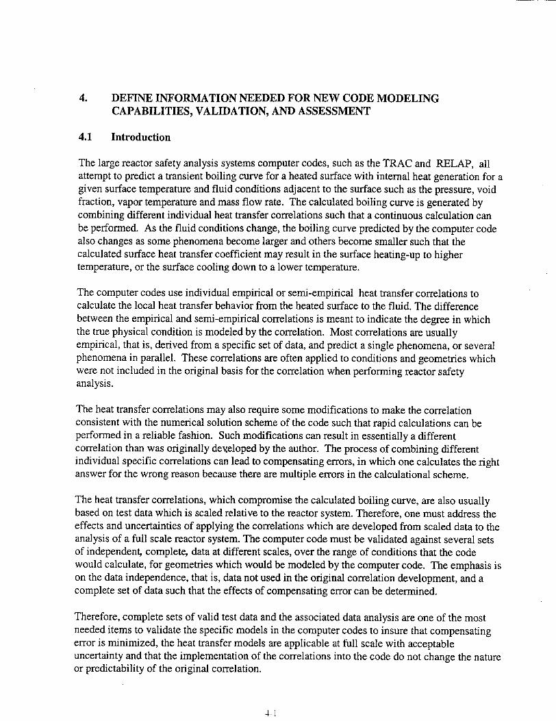
4. DEFINE INFORMATION NEEDED FOR NEW CODE MODELING CAPABILITIES, VALIDATION, AND ASSESSMENT
4.1 Introduction
The large reactor safety analysis systems computer codes, such as the TRAC and RELAP, all attempt to predict a transient boiling curve for a heated surface with internal heat generation for a given surface temperature and fluid conditions adjacent to the surface such as the pressure, void fraction, vapor temperature and mass flow rate. The calculated boiling curve is generated by combining different individual heat transfer correlations such that a continuous calculation can be performed. As the fluid conditions change, the boiling curve predicted by the computer code also changes as some phenomena become larger and others become smaller such that the calculated surface heat transfer coefficient may result in the surface heating-up to higher temperature, or the surface cooling down to a lower temperature.
The computer codes use individual empirical or semi-empirical heat transfer correlations to calculate the local heat transfer behavior from the heated surface to the fluid. The difference between the empirical and semi-empirical correlations is meant to indicate the degree in which the true physical condition is modeled by the correlation. Most correlations are usually empirical, that is, derived from a specific set of data, and predict a single phenomena, or several phenomena in parallel. These correlations are often applied to conditions and geometries which were not included in the original basis for the correlation when performing reactor safety analysis.
The heat transfer correlations may also require some modifications to make the correlation consistent with the numerical solution scheme of the code such that rapid calculations can be performed in a reliable fashion. Such modifications can result in essentially a different correlation than was originally dexzeloped by the author. The process of combining different individual specific correlations can lead to compensating errors, in which one calculates the right answer for the wrong reason because there are multiple errors in the calculational scheme.
The heat transfer correlations, which compromise the calculated boiling curve, are also usually based on test data which is scaled relative to the reactor system. Therefore, one must address the effects and uncertainties of applying the correlations which are developed from scaled data to the analysis of a full scale reactor system. The computer code must be validated against several sets of independent, complete, data at different scales, over the range of conditions that the code would calculate, for geometries which would be modeled by the computer code. The emphasis is on the data independence, that is, data not used in the original correlation development, and a complete set of data such that the effects of compensating error can be determined.
Therefore, complete sets of valid test data and the associated data analysis are one of the most needed items to validate the specific models in the computer codes to insure that compensating error is minimized, the heat transfer models are applicable at full scale with acceptable uncertainty and that the implementation of the correlations into the code do not change the nature or predictability of the original correlation.
4-1
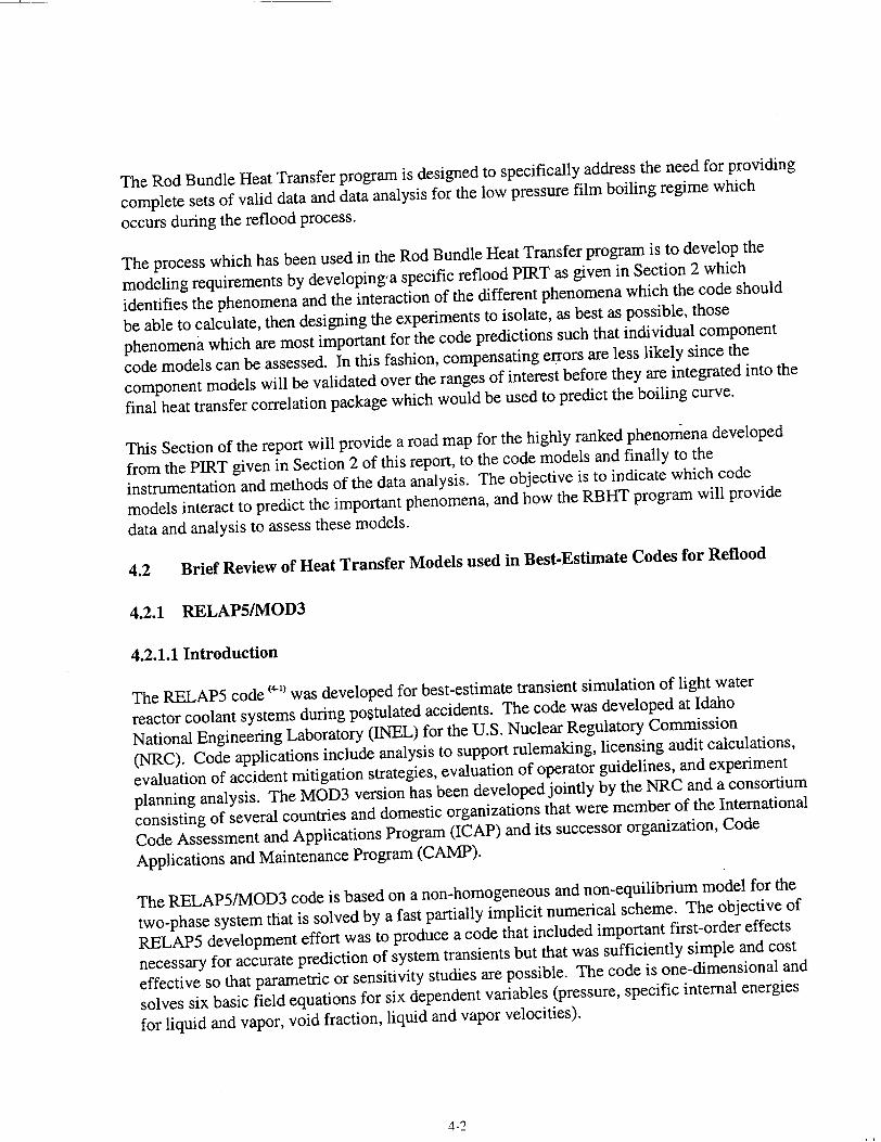
The Rod Bundle Heat Transfer program is designed to specifically address the need for providing
complete sets of valid data and data analysis for the low pressure film boiling regime which
occurs during the reflood process.
The process which has been used in the Rod Bundle Heat Transfer program is to develop the
modeling requirements by developing'a specific reflood PIRT as given in Section 2 which
identifies the phenomena and the interaction of the different phenomena which the code should
be able to calculate, then designing the experiments to isolate, as best as possible, those
phenomena which are most important for the code predictions such that individual component
code models can be assessed. In this fashion, compensating errors are less likely since the
component models will be validated over the ranges of interest before they are integrated into the
final heat transfer correlation package which would be used to predict the boiling curve.
This Section of the report will provide a road map for the highly ranked phenomena developed
from the PIRT given in Section 2 of this report, to the code models and finally to the
instrumentation and methods of the data analysis. The objective is to indicate which code
models interact to predict the important phenomena, and how the RBHT program will provide
data and analysis to assess these models.
4.2 Brief Review of Heat Transfer Models used in Best-Estimate Codes for Reflood
4.2.1 RELAP5IMOD3
4.2.1.1 Introduction
The RELAP5 code 4" was developed for best-estimate transient simulation of light water
reactor coolant systems during postulated accidents. The code was developed at Idaho
National Engineering Laboratory (INEL) for the U.S. Nuclear Regulatory Commission
(NRC). Code applications include analysis to support rulemaking, licensing audit calculations,
evaluation of accident mitigation strategies, evaluation of operator guidelines, and experiment
planning analysis. The MOD3 version has been developed jointly by the NRC and a consortium
consisting of several countries and domestic organizations that were member of the International
Code Assessment and Applications Program (ICAP) and its successor organization, Code
Applications and Maintenance Program (CAMP).
The RELAP5/MOD3 code is based on a non-homogeneous and non-equilibrium model for the
two-phase system that is solved by a fast partially implicit numerical scheme. The objective of
RELAP5 development effort was to produce a code that included important first-order effects
necessary for accurate prediction of system transients but that was sufficiently simple and cost
effective so that parametric or sensitivity studies are possible. The code is one-dimensional and
solves six basic field equations for six dependent variables (pressure, specific internal energies
for liquid and vapor, void fraction, liquid and vapor velocities).
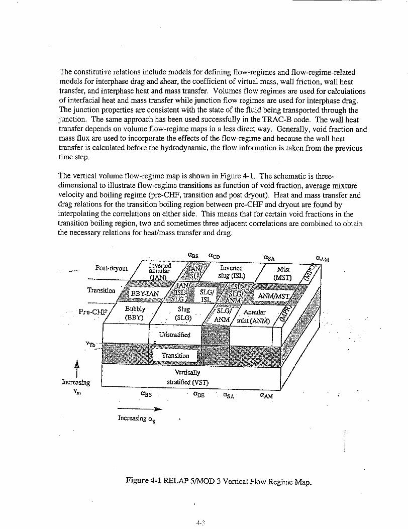
The constitutive relations include models for defining flow-regimes and flow-regime-related models for interphase drag and shear, the coefficient of virtual mass, wall friction, wall heat transfer, and interphase heat and mass transfer. Volumes flow regimes are used for calculations of interfacial heat and mass transfer while junction flow regimes are used for interphase drag. The junction properties are consistent with the state of the fluid being transported through the junction. The same approach has been used successfully in the TRAC-B code. The wall heat transfer depends on volume flow-regime maps in a less direct way. Generally, void fraction and mass flux are used to incorporate the effects of the flow-regime and because the wall heat transfer is calculated before the hydrodynamic, the flow information is taken from the previous time step.
The vertical volume flow-regime map is shown in Figure 4-1. The schematic is threedimensional to illustrate flow-regime transitions as function of void fraction, average mixture velocity and boiling regime (pre-CHF, transition and post dryout). Heat and mass transfer and drag relations for the transition boiling region between pre-CHF and dryout are found by interpolating the correlations on either side. This means that for certain void fractions in the transition boiling region, two and sometimes three adjacent correlations are combined to obtain the necessary relations for heat/mass transfer and drag.
aBS aCD
t Increasing sin
CSA OXA.M
aBS aDE .SA aAM
Increasing a.
Figure 4-1 RELAP 5/MOD 3 Vertical Flow Regime Map.
4-3

4.2.1.2 RELAP5/MOD3 Heat Transfer Package
The heat transfer is viewed as a two steps mechanism: (1) a wall to fluid bulk heat transfer and, (2) a bulk interfacial heat and mass transfer. In addition a separate, near-wall interfacial heat transfer is considered to account for the special case when the wall is communicating with a twophase mixture, for then boiling or condensation can occur as direct results of the wall heat transfer.
A boiling curve is used in RELAP5/MOD3 to govern the selection of the wall to fluid heat transfer correlations. The RELAP5 boiling curve logic is based on the value of the heat slab surface temperature. These correlations are based on fully developed steady-state flow while entrance effects are considered only for the calculation of Critical Heat Flux (CHF). Table 4-1 shows the heat transfer modes and corresponding correlations used while Figure 4-2 shows the wall heat transfer mode selection flow chart.
Single Phase Liquid
When the wall is subcooled and the void fraction is below 0.1, single-phase convection to liquid is assumed. For the vertical flow, depending on the value of the Re number, the heat transfer coefficient is calculated with either the Dittus-Boelter correlation (42' (forced turbulent convection) or Churchill-Chu correlation (4-) (natural convection). A constant Nu number equal to 4.6 is assumed for the forced laminar convection case.
Single Phase Vapor
In a similar fashion, when the wall is superheated and the quality is greater than 0.99, depending on the Re number, the Dittus-Boelter (42' and Churchill-Chu ('3) correlations are used for the single phase vapor convection.
Nucleate Boiling
When the wall is superheated the Chen correlation (") is used for both subcooled nucleate boiling and saturated nucleate boiling. Although the correlation was based on saturated liquid conditions, it is used for subcooled liquid conditions by using the bulk liquid temperature as the reference temperature for the convective part of the correlation. The wall is viewed as fully wetted by water except for vertically stratified conditions or, as the void fraction goes above 0.99, the heat transfer coefficient to liquid is ramped to zero at void fraction equal to 0.999 and the heat transfer to vapor is ramped up to the value obtained from the Dittus-Boelter correlation (4-2) The standard deviation for all the data considered in the Chen correlation development is stated as 11.6% for the saturated nucleate boiling conditions. The correlation was tested by Moles and Shaw (4-5) for the subcooled nucleate boiling regime where the data scatter is large (+180 to -60%). The data are generally underpredicted by the correlation.
4-4
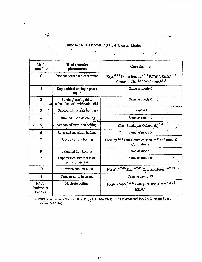
Table 4-1 RELAP 5/MOD 3 Heat Transfer Modes
Mode Heat transfer Correlations
number phenomena
0 Noncondensable-steam-water Kays,4 .2- Dittus-Boelter,42-2 ESDUa, Shah,4 2-3
Churchill.Chu,4.2-4 McAdams42-5
I Supercritical or single-phase Same as mode 0 liquid
2 ... Single-phase liquid or Same as mode 0 subcooled wall with voidg<0.l
- 3 Subcooled nucleate boiling Chen4 126
4 Saturated nucleate boiling Same as mode 3
5 Subcooled transition boiling Chen-Sundaram-Ozkaynak 4o 7
6 Saturated transition boiling Same as mode 5
7 Subcooled film boiliig Bromley, 4P- Sun-Gonzales-Tien, 4 2- 9 and mode 0 Correlations
8 Saturated film boiling Same as mode 7
9 Superciitical two-phase or Same as mode 0 single phase gas
10 Filmwise condensation Nusselt,42-1O.Shah,4 -11 Colburn-Hougen 4 --12
11 Condensation in steam Same as mode 10 4113 4.2-14
3,4 for Nucleate boiling Forster-Zuber, 2 " Poliey-Raiston-Grant, horizontal ESDUa bundles
a. ESDU (Engineering Science Data Unit, 73031, Nov 1973; ESDU International Pic, 27, Corsharn Street, London, N1 6UA)
4-5

RELAPS/MOD3.2
Figure 4-2 RELAP 5 wall heat transfer flow chart.
4-6
°