part 0: background reading & helpful tutorials (adxl335) 1. disconnect any sensors, etc. from...
TRANSCRIPT
COS 436 / ELE 469 Spring 2013 Last updated 3/1/13 10:53 AM
L2: Sensor Playground Wednesday lab: due 11:59 PM, 3/6/13 3/7/13*
Friday lab: due 11:59 PM, 3/8/13 3/8/13* Monday lab: due 11:59 PM, 3/11/13 3/12/13*
* We will extend this up to a maximum of two days if you contact us before (not on) the revised due date listed above, and explain why an extension is necessary for your lab to be of reasonable quality. As
discussed in class, extensions will not be granted for fine-tuning an already good lab to make it better. Work in your official group for this lab. Submission procedure and academic integrity guidelines are the same as outlined in the Lab 0 instructions. Part 0: Background reading & helpful tutorials 1. Required reading in textbook: Accelerometers: p. 229–230 RC circuits: p. 106–108 Sound: p. 353–354; scan rest of chapter 2. Optional tutorials, recommended if you get stuck or want inspiration: Arduino rctime tutorial: http://arduino.cc/en/Tutorial/RCtime Wikipedia article on RC circuits: http://en.wikipedia.org/wiki/RC_circuit Wikipedia article on piezoelectric sensors: http://en.wikipedia.org/wiki/Piezoelectric_sensor Accelerometers, in particular the ADXL335:
http://bildr.org/2011/04/sensing-orientation-with-the-adxl335-arduino/ (Note that our ADXL335s have breakout boards that have a different pin order than this
one, so don’t expect the code on that website to work without modification! Our breakouts also have a built-in voltage regulator, so it’s fine to power them at +5V.)
Part 1. The RC Time Constant; Using a capacitor to measure an FSR
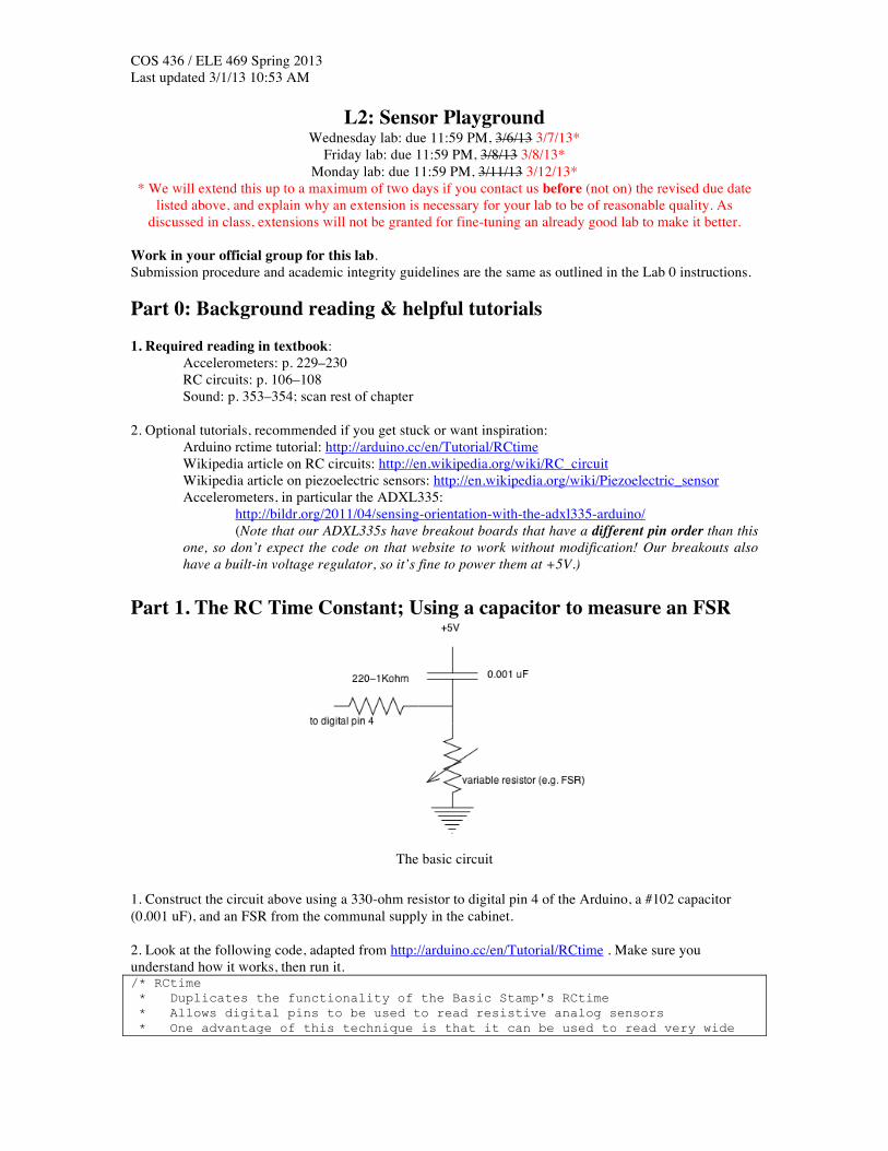
The basic circuit
1. Construct the circuit above using a 330-ohm resistor to digital pin 4 of the Arduino, a #102 capacitor (0.001 uF), and an FSR from the communal supply in the cabinet. 2. Look at the following code, adapted from http://arduino.cc/en/Tutorial/RCtime . Make sure you understand how it works, then run it. /* RCtime * Duplicates the functionality of the Basic Stamp's RCtime * Allows digital pins to be used to read resistive analog sensors * One advantage of this technique is that it can be used to read very wide
COS 436 / ELE 469 Spring 2013 Last updated 3/1/13 10:53 AM ranging inputs. * (The equivalent of 16 or 18 bit A/D) */ int sensorPin = 4; // 330 or 1k resistor connected to this pin long result = 0; void setup() // run once, when the sketch starts { Serial.begin(9600); Serial.println("start"); // a personal quirk } void loop() // run over and over again { Serial.println( RCtime(sensorPin) ); delay(10); } long RCtime(int sensPin){ long result = 0; pinMode(sensPin, OUTPUT); // make pin OUTPUT digitalWrite(sensPin, HIGH); // make pin HIGH to discharge capacitor delay(1); // wait a ms to make sure cap is discharged pinMode(sensPin, INPUT); // turn pin into an input and time till pin // goes low digitalWrite(sensPin, LOW); // turn pullups off - or it won't work while(digitalRead(sensPin)){ // wait for pin to go low result++; } return result; // report results } 3. Answer the following questions: Q1. What is the numerical range of the sensor circuit? (min, max values that could possibly be printed to serial monitor) Q2. True/false: Pressing harder on the FSR leads to a higher value output by the serial monitor. Q3. Explain why pressing harder on the FSR leads to a higher (or lower, depending on your answer to Q2) output value, based on your knowledge of how capacitors and resistors work.
Record your answers on paper. At the end of the lab, use the blackboard form for Lab2 to upload them.
Part 2. Measuring capacitance 1. Replace the #102 capacitor in the above circuit with a #104 capacitor (0.1 uF) 2. Answer the following questions: Q4. True/False: You have to press harder on the FSR now to make the output 0, compared to Part 1. Q5. Explain why increasing capacitance leads to the observed change in behavior.
Record your answers on paper. At the end of the lab, use the blackboard form for Lab2 to upload them.
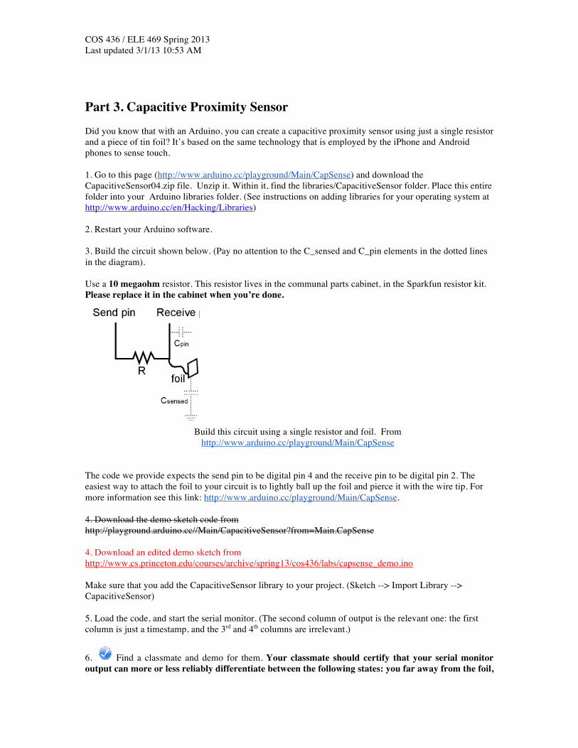
COS 436 / ELE 469 Spring 2013 Last updated 3/1/13 10:53 AM Part 3. Capacitive Proximity Sensor Did you know that with an Arduino, you can create a capacitive proximity sensor using just a single resistor and a piece of tin foil? It’s based on the same technology that is employed by the iPhone and Android phones to sense touch. 1. Go to this page (http://www.arduino.cc/playground/Main/CapSense) and download the CapacitiveSensor04.zip file. Unzip it. Within it, find the libraries/CapacitiveSensor folder. Place this entire folder into your Arduino libraries folder. (See instructions on adding libraries for your operating system at http://www.arduino.cc/en/Hacking/Libraries) 2. Restart your Arduino software. 3. Build the circuit shown below. (Pay no attention to the C_sensed and C_pin elements in the dotted lines in the diagram). Use a 10 megaohm resistor. This resistor lives in the communal parts cabinet, in the Sparkfun resistor kit. Please replace it in the cabinet when you’re done.
Build this circuit using a single resistor and foil. From
http://www.arduino.cc/playground/Main/CapSense The code we provide expects the send pin to be digital pin 4 and the receive pin to be digital pin 2. The easiest way to attach the foil to your circuit is to lightly ball up the foil and pierce it with the wire tip. For more information see this link: http://www.arduino.cc/playground/Main/CapSense. 4. Download the demo sketch code from http://playground.arduino.cc//Main/CapacitiveSensor?from=Main.CapSense 4. Download an edited demo sketch from http://www.cs.princeton.edu/courses/archive/spring13/cos436/labs/capsense_demo.ino Make sure that you add the CapacitiveSensor library to your project. (Sketch --> Import Library --> CapacitiveSensor) 5. Load the code, and start the serial monitor. (The second column of output is the relevant one: the first column is just a timestamp, and the 3rd and 4th columns are irrelevant.)
6. Find a classmate and demo for them. Your classmate should certify that your serial monitor output can more or less reliably differentiate between the following states: you far away from the foil,
COS 436 / ELE 469 Spring 2013 Last updated 3/1/13 10:53 AM you very close but not touching the foil, you touching the foil). Fill out the peer demo certification form (Lab #2, Part #3). 7. Return the resistor to the locker. You may keep the foil as a souvenir, use it in the last section of this lab, or gift it to a special friend. Part 4. Piezo Sensor 1. Disconnect all sensors, etc. from the terminals of the Arduino. 2. Grab a piezo element (pictured below) and a 1 megaohm resistor from the communal supply. (Return them when you’re done)
Piezo element
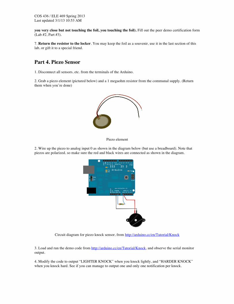
2. Wire up the piezo to analog input 0 as shown in the diagram below (but use a breadboard). Note that piezos are polarized, so make sure the red and black wires are connected as shown in the diagram.
Circuit diagram for piezo knock sensor, from http://arduino.cc/en/Tutorial/Knock
3. Load and run the demo code from http://arduino.cc/en/Tutorial/Knock, and observe the serial monitor output. 4. Modify the code to output “LIGHTER KNOCK” when you knock lightly, and “HARDER KNOCK” when you knock hard. See if you can manage to output one and only one notification per knock.
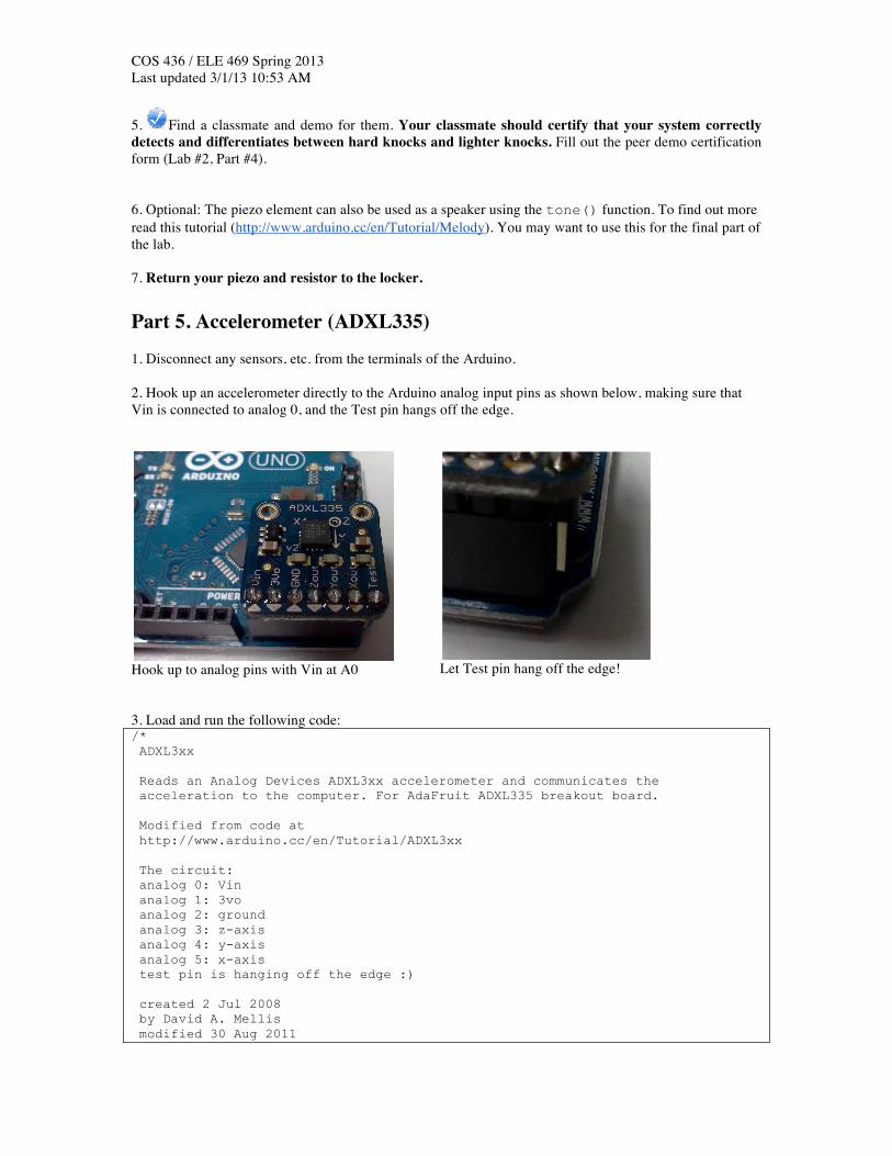
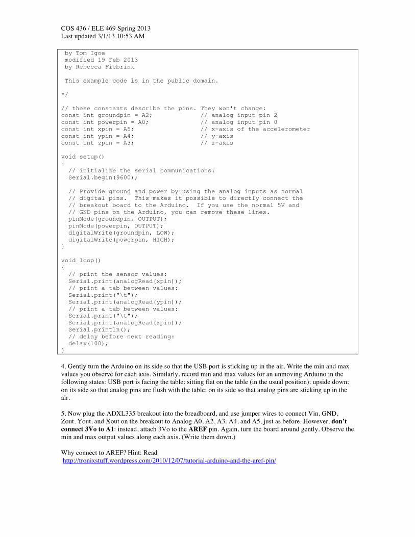
COS 436 / ELE 469 Spring 2013 Last updated 3/1/13 10:53 AM 5. Find a classmate and demo for them. Your classmate should certify that your system correctly detects and differentiates between hard knocks and lighter knocks. Fill out the peer demo certification form (Lab #2, Part #4). 6. Optional: The piezo element can also be used as a speaker using the tone() function. To find out more read this tutorial (http://www.arduino.cc/en/Tutorial/Melody). You may want to use this for the final part of the lab. 7. Return your piezo and resistor to the locker. Part 5. Accelerometer (ADXL335) 1. Disconnect any sensors, etc. from the terminals of the Arduino. 2. Hook up an accelerometer directly to the Arduino analog input pins as shown below, making sure that Vin is connected to analog 0, and the Test pin hangs off the edge.
Hook up to analog pins with Vin at A0
Let Test pin hang off the edge!
3. Load and run the following code: /* ADXL3xx Reads an Analog Devices ADXL3xx accelerometer and communicates the acceleration to the computer. For AdaFruit ADXL335 breakout board. Modified from code at http://www.arduino.cc/en/Tutorial/ADXL3xx The circuit: analog 0: Vin analog 1: 3vo analog 2: ground analog 3: z-axis analog 4: y-axis analog 5: x-axis test pin is hanging off the edge :) created 2 Jul 2008 by David A. Mellis modified 30 Aug 2011
COS 436 / ELE 469 Spring 2013 Last updated 3/1/13 10:53 AM by Tom Igoe modified 19 Feb 2013 by Rebecca Fiebrink This example code is in the public domain. */ // these constants describe the pins. They won't change: const int groundpin = A2; // analog input pin 2 const int powerpin = A0; // analog input pin 0 const int xpin = A5; // x-axis of the accelerometer const int ypin = A4; // y-axis const int zpin = A3; // z-axis void setup() { // initialize the serial communications: Serial.begin(9600); // Provide ground and power by using the analog inputs as normal // digital pins. This makes it possible to directly connect the // breakout board to the Arduino. If you use the normal 5V and // GND pins on the Arduino, you can remove these lines. pinMode(groundpin, OUTPUT); pinMode(powerpin, OUTPUT); digitalWrite(groundpin, LOW); digitalWrite(powerpin, HIGH); } void loop() { // print the sensor values: Serial.print(analogRead(xpin)); // print a tab between values: Serial.print("\t"); Serial.print(analogRead(ypin)); // print a tab between values: Serial.print("\t"); Serial.print(analogRead(zpin)); Serial.println(); // delay before next reading: delay(100); } 4. Gently turn the Arduino on its side so that the USB port is sticking up in the air. Write the min and max values you observe for each axis. Similarly, record min and max values for an unmoving Arduino in the following states: USB port is facing the table; sitting flat on the table (in the usual position); upside down; on its side so that analog pins are flush with the table; on its side so that analog pins are sticking up in the air. 5. Now plug the ADXL335 breakout into the breadboard, and use jumper wires to connect Vin, GND, Zout, Yout, and Xout on the breakout to Analog A0, A2, A3, A4, and A5, just as before. However, don’t connect 3Vo to A1: instead, attach 3Vo to the AREF pin. Again, turn the board around gently. Observe the min and max output values along each axis. (Write them down.) Why connect to AREF? Hint: Read http://tronixstuff.wordpress.com/2010/12/07/tutorial-arduino-and-the-aref-pin/

COS 436 / ELE 469 Spring 2013 Last updated 3/1/13 10:53 AM 6. Reattach the ADXL335 breakout directly to the Arduino pins, just as in Step 4. Plug in snugly and hold on tight to the Arduino and breakout. Have a teammate close and reopen the serial monitor. Then, immediately shake the board (with attached accelerometer) pretty vigorously back and forth. Grab the text in the serial monitor, copy it (it may help to turn off auto-scrolling), and paste into Matlab or Excel. Plot the data and take a look. Note the minimum and maximum values you observe along each axis. 7. Answer the following questions: Q6: What were the minimum and maximum values for each axis observed in Step 4? Q7. True/false The maximum value you observed in Step 5 above than in Step 4. Q8: Explain why the maximum value changed (either higher or lower) in Step 5, when you connected 3Vo to AREF. Q9: What were the minimum and maximum values for each axis observed in Step 6? Q10. The minimum and maximum values from Step 4 correspond to 1 and -1 Gs along each axis (when measured without using a connection to AREF). Given that, plus your observations from Step 6, how many Gs maximum (positive and negative) did your shaking in Step 6 induce? Q11. Go back and take measurements for flat, 45 degrees, and 90 degrees, -45 degrees, and -90 degrees tilt. Plot these values, number vs. tilt. True/false: The relationship between angle and output is linear.
Record your answers on paper. At the end of the lab, use the blackboard form for Lab2 to upload them. Part 6. Create Your Own Musical Instrument During the past few labs, you’ve learned how to sense various types of input from the physical world. For this last part of the lab, combine one or more sensors and one or more sound-making components to create your own musical instrument. To build this system, you may only use parts in the following list. (You are not obligated to use all, or even most, of these parts!) • The following parts in your lab kit:
o Arduino, wires, USB cord, breadboard, etc. (The obvious stuff) o Resistors o LEDs o Buttons o Rotary pot o Photocell o Flex sensor o Softpot (a variable resistor that detects changes in position, like a touch-sensitive slider) o Thermistor (a variable resistor that detects temperature changes) o Buzzer
• Communal parts (must not leave the lab, must be returned to box before you leave) o 1 FSR o 1 piezo element o 1 1-megaohm resistor, 1 10-megaohm resistor o 1 ADXL335 accelerometer
• Processing (e.g., for providing visual feedback, for sending OSC messages to sound synthesis environments)
• Sound synthesis software (see below) • A reasonable amount of communal materials (paper, cardboard, tape, tinfoil, etc.) To make sound, you have two options: Option 1: Use the buzzer that came with your lab kit.

COS 436 / ELE 469 Spring 2013 Last updated 3/1/13 10:53 AM • Photo and datasheet here: https://www.sparkfun.com/products/7950? • Use the Arduino tone() function to make sound: http://arduino.cc/en/Reference/Tone • Use a table like http://peabody.sapp.org/class/st2/lab/notehz/ to map from note names to frequencies, in
Hz, as required by the tone() function Option 2: OR you can use the piezo element as a speaker. • See example at http://www.arduino.cc/en/Tutorial/Melody Note that it is also possible to control computer-synthesized sound from Arduino, for example by receiving serial data from Arduino in a synthesis environment such as Max/MSP, or by using Processing to route from Arduino serial data to MIDI or OpenSoundControl messages. We don’t expect you to do this for the lab, but if you’d like to see some sample code (perhaps for use in a final project?), we’ve posted an example zip file at http://www.cs.princeton.edu/courses/archive/spring13/cos436/labs/ArduinoProcChuckExample.zip This zip contains an example of Arduino, Processing, and ChucK all working together. It requires you install the OSCP5 library for Processing and the ChucK programming language (and/or MiniAudicle ChucK IDE). Steps: 1. Experiment with building at least three different instrument prototypes. Each of these might use the same hardware, but a different mapping from user actions to sound. Or, they could all make essentially the same sound, but the user might control it in different ways. Your prototypes might all be extremely different from one another, or they could be similar variations on the same theme. Do whatever you think will be most interesting and helpful. Document each prototype using video, or photos + audio. (Try out Audacity, a free audio editor, if you want an easy way to record audio: http://audacity.sourceforge.net/). 2. Choose your favorite prototype and refine it until you are satisfied with its musicality. (You can define musicality however you want.) Record a performance, documented using either video or photos + audio.
3. Document your completed system in a WordPress blog. Create a new blog post, then: a. Add it to the “Lab2” category. b. Include the following in your post: i. The names of everyone in your group (just first names are fine) ii. Your group number
iii. A short description of what you built, why, and your assessment of its success. You should mention what you liked about the final result, and you should indicate your opinion on what didn’t work, or what you might like to do differently. All this text should be no more than one paragraph. iv. Video or audio + photo documentation of each of your prototypes, each accompanied by 1-2 sentences about what the prototype does. v. Ideally, video showing your performance on your final system, with short caption(s). If you can’t capture video, document with photos and audio. vi. A list of parts used in your final system vii. Instructions that would be sufficient for someone else to recreate your design exactly. (This should be no more than one paragraph.) viii. Your entire source code for your final instrument in Part 6. If the code isn’t too long, copy-paste directly into your writeup, and format the code using either the <pre> tag (if you’re in the HTML editing interface) or using the “Preformatted” style, which you can access using the “kitchen sink” button, shown below. Or, if you have lots of code, you can upload it somewhere (e.g., Princeton WebSpace) and include a link to it.
4. Hit “Publish” to publish your blog post.
COS 436 / ELE 469 Spring 2013 Last updated 3/1/13 10:53 AM 5. Fill out the Blackboard form for Lab 2 with answers to all the above questions. Also provide your group member NetIDs, your group number, and the URL to your blog. 6. Return any communal equipment, tools, etc. to the cabinet. Place your lab kit components in your cupboard and/or take them with you. Grading Rubric: Parts 1–5: Graded on correct responses to questions and presence of peer demo forms. Worth 2 points per question, 4 points per peer demo, for a total of 30 points. Part 6: Worth 30 points total. Graded on: a) Completeness and quality of documentation: 10 points
0 points: missing/incomplete 6 points: documentation is there but missing key information, missing video/photos+audio, or unclear, or an inappropriate length 10 points: thorough enough for a novice to follow your instructions and re-create easily
b) Documented design process and critical self-reflection: 10 points 0 points: missing/incomplete 6 points: documentation is there but missing some information, or not presented clearly, or an inappropriate length
10 points: includes at least 3 prototypes; includes thoughtful reflection on what worked and what didn’t; describes motivation or inspiration for your system
c) Creativity & coolness: 10 points 0 points: bare minimum, looks just like existing tutorials or previous parts of the lab 6 points: result differs substantially from existing tutorials, shows independent thought 10 points: Mind-blowingly awesome; better than anything the TAs would have come up with