parker pneumatic vacuum cups - files.valinonline.com · catalog pdn1000us pneumatic products u.s....
TRANSCRIPT

Catalog PDN1000US Pneumatic Products U.S. Parker Pneumatic 5-Year Extended Warranty
Roger Sherrard President Automation Group
The Parker 5Year Extended Warranty
P arker Hannifin Corporation will extend its warranty on all pneumatic components to sixty (60) months
providing they are correctly installed and protected by Parker pneumatic filters which are properly maintained.
Components covered by this warranty include all cylinders, valves and pneumatic automation components
manufactured by Parker in any of our global facilities. This warranty covers our components anywhere in the world
you may ship your equipment.
Parker's obligation under this warranty is limited to the replacement or repair of any failed components.
The buyer understands that the seller will not be liable for any other costs or damages.
The buyers of quality Parker components and filters benefit by having ONE source for all pneumatic needs Parker.
Parker Hannifin Corporation Pneumatic Division Richland, Michigan www.parker.com/pneumatics
Parker Hannifin Corporation Pneumatic Division Richland, Michigan www.parker.com/pneumatics
A1
Catalog PDN1000US
Parker Pneumatic
A
Inde
x
! WARNING FAILURE OR IMPROPER SELECTION OR IMPROPER USE OF THE PRODUCTS AND/OR SYSTEMS DESCRIBED HEREIN OR RELATED ITEMS CAN CAUSE DEATH, PERSONAL INJURY AND PROPERTY DAMAGE. This document and other information from Parker Hannifin Corporation, its subsidiaries and authorized distributors provide product and/or system options for further investigation by users having technical expertise. It is important that you analyze all aspects of your application including consequences of any failure, and review the information concerning the product or system in the current product catalog. Due to the variety of operating conditions and applications for these products or systems, the user, through its own analysis and testing, is solely responsible for making the final selection of the products and systems and assuring that all performance, safety and warning requirements of the application are met. The products described herein, including without limitation, product features, specifications, designs, availability and pricing, are subject to change by Parker Hannifin Corporation and its subsidiaries at any time without notice.
Offer of Sale The items described in this document are hereby offered for sale by Parker Hannifin Corporation, its subsidiaries or its authorized distributors. This offer and its acceptance are governed by the provisions stated on the separate page of this document entitled “Offer of Sale”.
© Copyright 2011 Parker Hannifin Corporation. All Rights Reserved
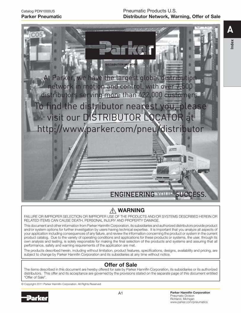
DISTRIBUTION NETWORK
At Parker, we have the largest global distribution network in motion and control, with over 7,500
distributors serving more than 422,000 customers.
To find the distributor nearest you, please visit our DISTRIBUTOR LOCATOR at
http://www.parker.com/pneu/distributor
ENGINEERING YOUR SUCCESS.
Pneumatic Products U.S. Distributor Network, Warning, Offer of Sale
Parker Hannifin Corporation Pneumatic Division Richland, Michigan www.parker.com/pneumatics
C42
Catalog PDN1000US
Parker Pneumatic
C
Vacuum C
ups Vacuum
Products
Vacuum Cups PCG Multiple Bellows Vacuum Cups
Features • Soft touch
• Extra level compensation
• Flexible sealing lip for irregular curved surfaces
• 5mm to 90mm in diameter
Specifications
Cup material Nitrile Nitrile ESD* Silicon
Silicon ESD* Urethane
Material code NBR NBRE SI SIE U
Operating temperature (°C)
-20° to +120°
-30° to +120°
-60° to +250°
-60° to +250°
-30° to +120°
Color Black Black / Blue Dot White Black /
Red Dot Blue
Hardness, shore A (°Sh) 55 ±5 70 ±5 55 ±5 55 ±5 55 ±5
Electrical resistance (Ωm) — 800
to 1000 — 800 to 1000 —
* ESD: Electric Static Dissipative Material
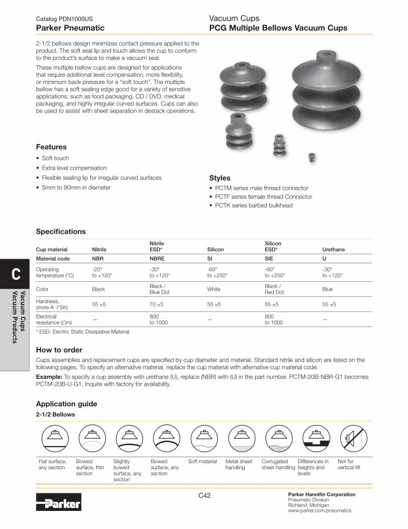
2-1/2 bellows design minimizes contact pressure applied to the product. The soft seal lip and touch allows the cup to conform to the product’s surface to make a vacuum seal.
These multiple bellow cups are designed for applications that require additional level compensation, more flexibility, or minimum back pressure for a “soft touch”. The multiple bellow has a soft sealing edge good for a variety of sensitive applications; such as food packaging, CD / DVD, medical packaging, and highly irregular curved surfaces. Cups can also be used to assist with sheet separation in destack operations.
Styles • PCTM series male thread connector • PCTF series female thread Connector • PCTK series barbed bulkhead
How to order Cups assemblies and replacement cups are specified by cup diameter and material. Standard nitrile and silicon are listed on the following pages. To specify an alternative material, replace the cup material with alternative cup material code.
Example: To specify a cup assembly with urethane (U), replace (NBR) with (U) in the part number. PCTM-20B-NBR-G1 becomes PCTM-20B-U-G1. Inquire with factory for availability.
Application guide 2-1/2 Bellows
Flat surface, any section
Bowed surface, thin section
Slightly bowed surface, any section
Bowed surface, any section
Soft material Metal sheet handling
Corrugated sheet handling
Differences in heights and levels
Not for vertical lift

Parker Hannifin Corporation Pneumatic Division Richland, Michigan www.parker.com/pneumatics
C43
Catalog PDN1000US
Parker Pneumatic
C
Vacu
um C
ups
Vacu
um P
rodu
cts
Vacuum Cups PCG Multiple Bellows Vacuum Cups
Tube I.D.
Mounting Thread.
Note: When installing cup assemblies, use a sealant material to secure the assembly and prevent vacuum leakage.
PCTM Series Male Thread Connector Simple male connection for low profile positions secured to a plate or bracket. NPT, G, metric threads. Fitting material: aluminum.
Installation
Cup diameter (mm)
Vacuum port
Complete assembly Nitrile (NBR)
Replacement cup Nitrile (NBR)
Complete assembly Silicon (SI)
Replacement cup Silicon (SI)
Replacement cup fitting
5 M5 PCTM-5-NBR-M5 PCG-5-NBR PCTM-5-SI-M5 PCG-5-SI FTM-5A-M5H
7 M5 PCTM-7-NBR-M5 PCG-7-NBR PCTM-7-SI-M5 PCG-7-SI FTM-5A-M5H
10 M5 PCTM-10-NBR-M5 PCG-10-NBR PCTM-10-SI-M5 PCG-10-SI CTM-10-M5H
10 G1 PCTM-10-NBR-G1 PCG-10-NBR PCTM-10-SI-G1 PCG-10-SI CTM-10-G1H
15 M5 PCTM-15-NBR-M5 PCG-15-NBR PCTM-15-SI-M5 PCG-15-SI CTM-10-M5H
15 G1 PCTM-15-NBR-G1 PCG-15-NBR PCTM-15-SI-G1 PCG-15-SI CTM-10-G1H
20 M5 PCTM-20-NBR-M5 PCG-20-NBR PCTM-20-SI-M5 PCG-20-SI CTM-10-M5H
20 G1 PCTM-20-NBR-G1 PCG-20-NBR PCTM-20-SI-G1 PCG-20-SI CTM-10-G1H
30 G1 PCTM-30-NBR-G1 PCG-30-NBR PCTM-30-SI-G1 PCG-30-SI CTM-30-G1H
30 G2 PCTM-30-NBR-G2 PCG-30-NBR PCTM-30-SI-G2 PCG-30-SI CTM-30-G2
30 N1 PCTM-30-NBR-N1 PCG-30-NBR PCTM-30-SI-N1 PCG-30-SI CTM-30-N1
40 G1 PCTM-40-NBR-G1 PCG-40-NBR PCTM-40-SI-G1 PCG-40-SI CTM-30-G1H
40 G2 PCTM-40-NBR-G2 PCG-40-NBR PCTM-40-SI-G2 PCG-40-SI CTM-30-G2
40 N1 PCTM-40-NBR-N1 PCG-40-NBR PCTM-40-SI-N1 PCG-40-SI CTM-30-N1
60 G1 PCTM-60-NBR-G1 PCG-60-NBR PCTM-60-SI-G1 PCG-60-SI CTM-30-G1H
60 N1 PCTM-60-NBR-N1 PCG-60-NBR PCTM-60-SI-N1 PCG-60-SI CTM-30-N1
90 G2 PCTM-90-NBR-G2 PCG-90-NBR PCTM-90-SI-G2 PCG-90-SI CTM-90-G2
90 N2 PCTM-90-NBR-N2 PCG-90-NBR PCTM-90-SI-N2 PCG-90-SI CTM-90-N2
Most popular.
Parker Hannifin Corporation Pneumatic Division Richland, Michigan www.parker.com/pneumatics
C44
Catalog PDN1000US
Parker Pneumatic
C
Vacuum C
ups Vacuum
Products
Vacuum Cups PCG Multiple Bellows Vacuum Cups
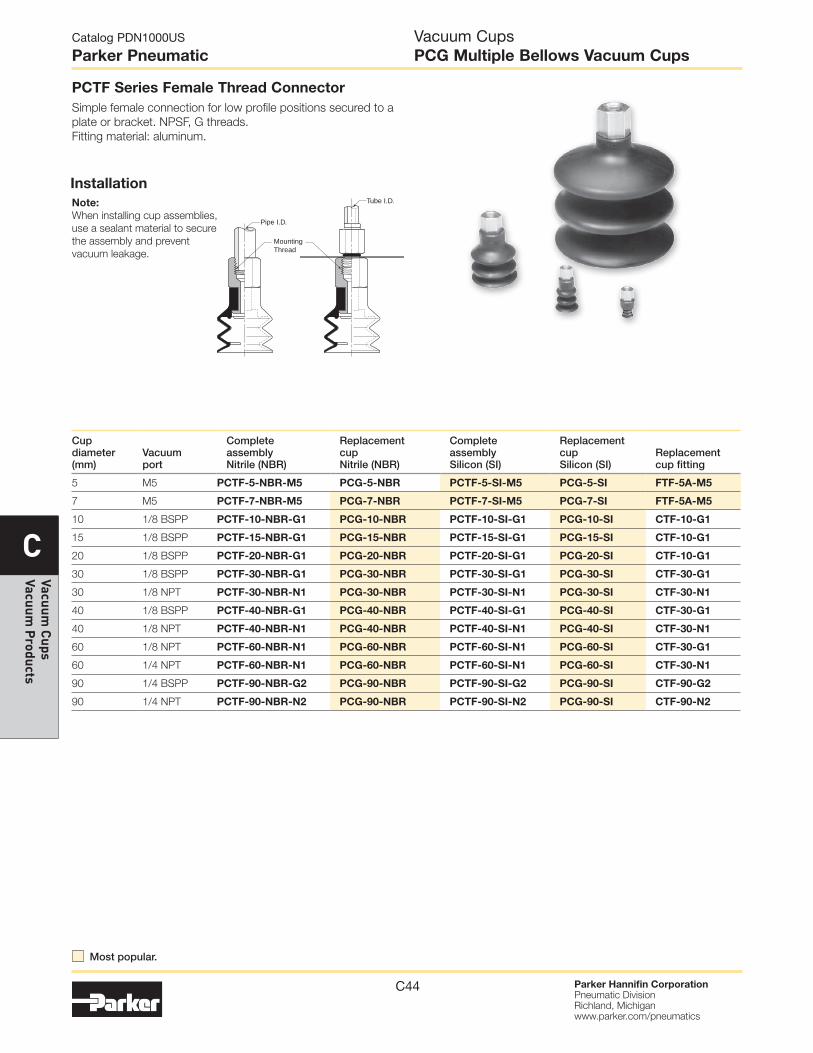
PCTF Series Female Thread Connector Simple female connection for low profile positions secured to a plate or bracket. NPSF, G threads. Fitting material: aluminum.
Installation Tube I.D.
Pipe I.D.
Mounting Thread
Note: When installing cup assemblies, use a sealant material to secure the assembly and prevent vacuum leakage.
Cup diameter (mm)
Vacuum port
Complete assembly Nitrile (NBR)
Replacement cup Nitrile (NBR)
Complete assembly Silicon (SI)
Replacement cup Silicon (SI)
Replacement cup fitting
5 M5 PCTF-5-NBR-M5 PCG-5-NBR PCTF-5-SI-M5 PCG-5-SI FTF-5A-M5
7 M5 PCTF-7-NBR-M5 PCG-7-NBR PCTF-7-SI-M5 PCG-7-SI FTF-5A-M5
10 1/8 BSPP PCTF-10-NBR-G1 PCG-10-NBR PCTF-10-SI-G1 PCG-10-SI CTF-10-G1
15 1/8 BSPP PCTF-15-NBR-G1 PCG-15-NBR PCTF-15-SI-G1 PCG-15-SI CTF-10-G1
20 1/8 BSPP PCTF-20-NBR-G1 PCG-20-NBR PCTF-20-SI-G1 PCG-20-SI CTF-10-G1
30 1/8 BSPP PCTF-30-NBR-G1 PCG-30-NBR PCTF-30-SI-G1 PCG-30-SI CTF-30-G1
30 1/8 NPT PCTF-30-NBR-N1 PCG-30-NBR PCTF-30-SI-N1 PCG-30-SI CTF-30-N1
40 1/8 BSPP PCTF-40-NBR-G1 PCG-40-NBR PCTF-40-SI-G1 PCG-40-SI CTF-30-G1
40 1/8 NPT PCTF-40-NBR-N1 PCG-40-NBR PCTF-40-SI-N1 PCG-40-SI CTF-30-N1
60 1/8 NPT PCTF-60-NBR-N1 PCG-60-NBR PCTF-60-SI-N1 PCG-60-SI CTF-30-G1
60 1/4 NPT PCTF-60-NBR-N1 PCG-60-NBR PCTF-60-SI-N1 PCG-60-SI CTF-30-N1
90 1/4 BSPP PCTF-90-NBR-G2 PCG-90-NBR PCTF-90-SI-G2 PCG-90-SI CTF-90-G2
90 1/4 NPT PCTF-90-NBR-N2 PCG-90-NBR PCTF-90-SI-N2 PCG-90-SI CTF-90-N2
Most popular.

Parker Hannifin Corporation Pneumatic Division Richland, Michigan www.parker.com/pneumatics
C45
Catalog PDN1000US
Parker Pneumatic
C
Vacu
um C
ups
Vacu
um P
rodu
cts
Vacuum Cups PCG Multiple Bellows Vacuum Cups
PCTK Series Barbed Bulkhead Top stem connectors secured with jam nuts and allow tubing connections at the top side. Fitting material: Nickel plated brass.
Installation Tube I.D.
Mounting Thread
Cup Screw
Note: When installing cup assemblies, use a sealant material to secure the assembly and prevent vacuum leakage.
Cup diameter (mm)
Vacuum port
Complete assembly Nitrile (NBR)
Replacement cup Nitrile (NBR)
Complete assembly Silicon (SI)
Replacement cup Silicon (SI)
Replacement cup fitting
5 Barb PCTK-5-NBR PCG-5-NBR PCTK-5-SI PCG-5-SI FTK-5A
7 Barb PCTK-7-NBR PCG-7-NBR PCTK-7-SI PCG-7-SI FTK-5A
10 Barb PCTK-10-NBR PCG-10-NBR PCTK-10-SI PCG-10-SI CTK-10
15 Barb PCTK-15-NBR PCG-15-NBR PCTK-15-SI PCG-15-SI CTK-10
20 Barb PCTK-20-NBR PCG-20-NBR PCTK-20-SI PCG-20-SI CTK-10
30 Barb PCTK-30-NBR PCG-30-NBR PCTK-30-SI PCG-30-SI CTK-30
40 Barb PCTK-40-NBR PCG-40-NBR PCTK-40-SI PCG-40-SI CTK-30
60 Barb PCTK-60-NBR PCG-60-NBR PCTK-60-SI PCG-60-SI CTK-30
90 NPT PCTK-90-NBR-N1 PCG-90-NBR PCTK-90-SI-N1 PCG-90-SI CTK-90-N1
90 BSPP PCTK-90-NBR-G1 PCG-90-NBR PCTK-90-SI-G1 PCG-90-SI CTK-90-G1
Most popular.

Parker Hannifin Corporation Pneumatic Division Richland, Michigan www.parker.com/pneumatics
C46
Catalog PDN1000US
Parker Pneumatic
C
Vacuum C
ups Vacuum
Products
Model number ØA ØB ØC ØD E F G H J
PCG-5-* .20 (5) .16 (4) .08 (2) .30 (7.5) .37 (9.5) .12 (3) .16 (4) .08 (2) .24 (6)
PCG-7-* .28 (7) .16 (4) .08 (2) .30 (7.5) .39 (10) .12 (3) .16 (4) .08 (2) .24 (6)
PCG-10-* .35 (9) .20 (5) — — .59 (15) .12 (3) .28 (7) — .35 (9)
PCG-15-* .60 (15.2) .20 (5) — — .90 (22) .39 (10) .35 (9) — .39 (10)
PCG-20-* .79 (20) .20 (5) — — .91 (23) .39 (10) .35 (9) — .39 (10)
PCG-30-* 1.26 (32) .31 (8) — — 1.48 (37.5) .57 (14.5) .67 (17) .51 (13) .71 (18)
PCG-40-* 1.65 (42) .31 (8) — — 1.81 (46) .87 (22) .67 (17) .51 (13) .79 (20)
PCG-60-* 2.44 (62) .31 (8) — — 2.17 (55) 1.06 (27) .71 (18) .51 (13) .85 (21.5)
PCG-90-* 3.46 (88) .47 (12) — — 3.44 (87.5) 1.65 (42) 1.02 (26) .79 (20) .98 (25)
Inches (mm) * Cup material
PCG-5 and PCG-7
PCG-10 thru PCG-20
PCG-30 thru PCG-60
PCG-90
A
E
F
B J
HG
E F
D J
C A
B
G
H
A
E
F
B
J
H
A
E
F
H G
B
J
PCG Series Replacement Cup Dimensions
Vacuum Cups PCG Multiple Bellows Vacuum Cups

Parker Hannifin Corporation Pneumatic Division Richland, Michigan www.parker.com/pneumatics
C47
Catalog PDN1000US
Parker Pneumatic
C
Vacu
um C
ups
Vacu
um P
rodu
cts
SW8
M5: M5
E
B
C D
A A
B
E
C
D
5/16"
M5: M5 G1: 1/8 BSPP
PCTM-5 and PCTM-7
PCTM-10 thru PCTM-20
Model number ØA B
C (M5)
C (N1 / G1)
C (M10 / G2)
C (N2) D E
PCTM-5-*-† .20 (5) .51 (13) .18 (4.5) — — — .14 (3.5) .12 (3)
PCTM-7-*-† .28 (7) .53 (13.5) .18 (4.5) — — — .14 (3.5) .12 (3)
PCTM-10-*-† .35 (9) .69 (17.5) .18 (4.5) .31 (8) — — .10 (2.5) .12 (3)
PCTM-15-*-† .60 (15.2) 1.04 (25.5) .18 (4.5) .31 (8) — — .10 (2.5) .39 (10)
PCTM-20-*-† .79 (20) 1.04 (25.5) .18 (4.5) .31 (8) — — .10 (2.5) .39 (10)
PCTM-30-*-† 1.26 (32) 1.67 (42.5) — .31 (8) .39 (10) — .20 (5) .57 (14.5)
PCTM-40-*-† 1.65 (42) 2.01 (51) — .31 (8) .39 (10) — .20 (5) .87 (22)
PCTM-60-*-† 2.44 (62) 2.36 (60) — .31 (8) .39 (10) — .20 (5) 1.06 (27)
PCTM-90-*-† 3.46 (88) 3.64 (92.5) — — .39 (10) .59 (15) .20 (5) 1.65 (42)
Inches (mm) * Cup material † Thread size
PCTM-90
PCTM-30 thru PCTM-60
A
B
E
N1: 1/8 NPT G1: 1/8 BSPP G2: 1/4 BSPP
1/2" C
D B
E
N2: 1/4 NPT G2: 1/4 BSPP
9/16" C
D
A
Dimensions
Vacuum Cups PCTM Series Assemblies
Parker Hannifin Corporation Pneumatic Division Richland, Michigan www.parker.com/pneumatics
C48
Catalog PDN1000US
Parker Pneumatic
C
Vacuum C
ups Vacuum
Products
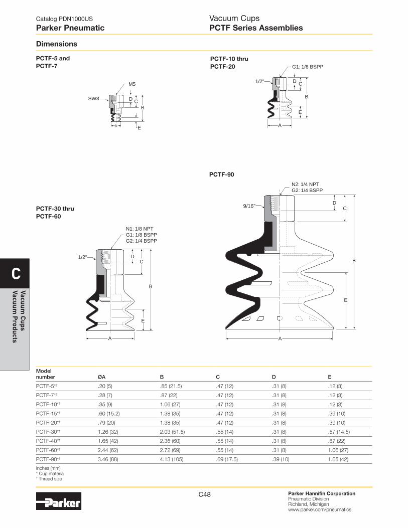
PCTF-5 and PCTF-7
PCTF-10 thru PCTF-20
Model number ØA B C D E
PCTF-5*† .20 (5) .85 (21.5) .47 (12) .31 (8) .12 (3)
PCTF-7*† .28 (7) .87 (22) .47 (12) .31 (8) .12 (3)
PCTF-10*† .35 (9) 1.06 (27) .47 (12) .31 (8) .12 (3)
PCTF-15*† .60 (15.2) 1.38 (35) .47 (12) .31 (8) .39 (10)
PCTF-20*† .79 (20) 1.38 (35) .47 (12) .31 (8) .39 (10)
PCTF-30*† 1.26 (32) 2.03 (51.5) .55 (14) .31 (8) .57 (14.5)
PCTF-40*† 1.65 (42) 2.36 (60) .55 (14) .31 (8) .87 (22)
PCTF-60*† 2.44 (62) 2.72 (69) .55 (14) .31 (8) 1.06 (27)
PCTF-90*† 3.46 (88) 4.13 (105) .69 (17.5) .39 (10) 1.65 (42)
Inches (mm) * Cup material † Thread size
PCTF-90
PCTF-30 thru PCTF-60
E
B CD
A
M5
SW8
A
B
E
CD
G1: 1/8 BSPP
1/2"
A
B
E
C D
N1: 1/8 NPT G1: 1/8 BSPP G2: 1/4 BSPP
1/2" B
E
C D
A
9/16"
N2: 1/4 NPT G2: 1/4 BSPP
Dimensions
Vacuum Cups PCTF Series Assemblies

Parker Hannifin Corporation Pneumatic Division Richland, Michigan www.parker.com/pneumatics
C49
Catalog PDN1000US
Parker Pneumatic
C
Vacu
um C
ups
Vacu
um P
rodu
cts
PCTK-5 and PCTK-7
PCTK-10 thru PCTK-20
Model number ØA B C D E F G
Wt oz. (g)
PCTK-5-* .20 (5) 1.32 (33.5) .39 (10) .55 (14) .12 (3) .47 (12) .12 (3) .56 (11)
PCTK-7-* .28 (7) 1.34 (34) .39 (10) .55 (14) .12 (3) .47 (12) .12 (3) .56 (11)
PCTK-10-* .35 (9) 2.21 (56.2) .63 (16) .88 (22.5) .12 (3) .59 (15) .16 (4) .78 (22)
PCTK-15-* .60 (15.2) 2.53 (64.2) .63 (16) .86 (22) .39 (10) .59 (15) .16 (4) .78 (22)
PCTK-20-* .79 (20) 2.53 (64.2) .63 (16) .86 (22) .39 (10) .59 (15) .16 (4) .78 (22)
PCTK-30-* 1.26 (32) 3.42 (86.8) .63 (16) 1.26 (32) .57 (14.5) .79 (20) .20 (5) 1.62 (46)
PCTK-40-* 1.65 (42) 3.75 (95.3) .63 (16) 1.26 (32) .86 (22) .79 (20) .20 (5) 1.94 (55)
PCTK-60-* 2.44 (62) 4.11 (104.3) .63 (16) 1.26 (32) 1.06 (27) .79 (20) .20 (5) 3.00 (85)
PCYK-90-* 3.46 (88) 5.70 (144.8) .91 (23) 2.17 (55) 1.65 (42) .43 (11) — 10.58 (300)
Inches (mm) * Cup material † Vacuum port
PCTK-30 thru PCTK-60
Dimensions
EA
.197 Dia. Ø (5)
.098 Dia. Ø (2.5)
FG
C
D B
M9x1.0 SW12
B
FG
C
D
M8x1.25
SW12
.197 Dia. Ø (5)
.118 Dia. Ø (3)
E
A
B
FG
C
D
M10x1.5
SW14
.197 Dia. Ø (5) .118 Dia.
Ø (3)
A
E
M5x0.8
Vacuum Cups PCTK Series Assemblies
PCTK-90 N1: 1/8 NPT G1: 1/8 BSPP R1: 1/8 BSPT
N1: 1/8 NPT G1: 1/8 BSPP R1: 1/8 BSPT
SW21
M16x1.5
B
FG
D
A
E

ParkerHannifinCorporation Pneumatic Division Richland, Michigan www.parker.com/pneumatics
G5
G
Safe
ty G
uide
, O
ffer
of S
ale
Safety Guide For Selecting And Using Pneumatic Division Products And Related Accessories
WARNING: FAILURE OR IMPROPER SELECTION OR IMPROPER USE OF PNEUMATIC DIVISION PRODUCTS, ASSEMBLIES OR RELATED ITEMS (“PRODUCTS”) CAN CAUSE DEATH, PERSONAL INJURY, AND PROPERTY DAMAGE. POSSIBLE CONSEQUENCES OF FAILURE OR IMPROPER SELECTION OR IMPROPER USE OF THESE PRODUCTS INCLUDE BUT ARE NOT LIMITED TO: • Unintended or mistimed cycling or motion of machine members or failure to cycle
• Work pieces or component parts being thrown off at high speeds.
• Failure of a device to function properly for example, failure to clamp or unclamp an associated item or device.
• Explosion
• Suddenly moving or falling objects.
• Release of toxic or otherwise injurious liquids or gasses.
Before selecting or using any of these Products, it is important that you read and follow the instructions below.
!
Pneumatic Products Safety Guide, Control Products
1. GENERAL INSTRUCTIONS 1.1. Scope: This safety guide is designed to cover general guidelines on the installation, use, and maintenance of Pneumatic Division
Valves, FRLs (Filters, Pressure Regulators, and Lubricators), Vacuum products and related accessory components. 1.2. Fail-Safe: Valves, FRLs, Vacuum products and their related components can and do fail without warning for many reasons. Design all
systems and equipment in a fail-safe mode, so that failure of associated valves, FRLs or Vacuum products will not endanger persons or property.
1.3 Relevant International Standards: For a good guide to the application of a broad spectrum of pneumatic fluid power devices see: ISO 4414:1998, Pneumatic Fluid Power – General Rules Relating to Systems. See www.iso.org for ordering information.
1.4. Distribution: Provide a copy of this safety guide to each person that is responsible for selection, installation, or use of Valves, FRLs or Vacuum products. Do not select, or use Parker valves, FRLs or vacuum products without thoroughly reading and understanding this
safety guide as well as the specific Parker publications for the products considered or selected. 1.5. User Responsibility: Due to the wide variety of operating conditions and applications for valves, FRLs, and vacuum products Parker
and its distributors do not represent or warrant that any particular valve, FRL or vacuum product is suitable for any specific end use system. This safety guide does not analyze all technical parameters that must be considered in selecting a product. The user, through its own analysis and testing, is solely responsible for: • Making the final selection of the appropriate valve, FRL, Vacuum component, or accessory. • Assuring that all user’s performance, endurance, maintenance, safety, and warning requirements are met and that the application
presents no health or safety hazards. • Complying with all existing warning labels and / or providing all appropriate health and safety warnings on the equipment on which
the valves, FRLs or Vacuum products are used; and, • Assuring compliance with all applicable government and industry standards.
1.6. Safety Devices: Safety devices should not be removed, or defeated. 1.7. Warning Labels: Warning labels should not be removed, painted over or otherwise obscured. 1.8. Additional Questions: Call the appropriate Parker technical service department if you have any questions or require any additional
information. See the Parker publication for the product being considered or used, or call 1-800-CPARKER, or go to www.parker.com, for telephone numbers of the appropriate technical service department.
2. PRODUCT SELECTION INSTRUCTIONS 2.1. Flow Rate: The flow rate requirements of a system are frequently the primary consideration when designing any pneumatic system.
System components need to be able to provide adequate flow and pressure for the desired application. 2.2. Pressure Rating: Never exceed the rated pressure of a product. Consult product labeling, Pneumatic Division catalogs or the
instruction sheets supplied for maximum pressure ratings. 2.3. Temperature Rating: Never exceed the temperature rating of a product. Excessive heat can shorten the life expectancy of a product
and result in complete product failure. 2.4. Environment: Many environmental conditions can affect the integrity and suitability of a product for a given application. Pneumatic
Division products are designed for use in general purpose industrial applications. If these products are to be used in unusual circumstances such as direct sunlight and/or corrosive or caustic environments, such use can shorten the useful life and lead to premature failure of a product.
2.5. Lubrication and Compressor Carryover: Some modern synthetic oils can and will attack nitrile seals. If there is any possibility of synthetic oils or greases migrating into the pneumatic components check for compatibility with the seal materials used. Consult the factory or product literature for materials of construction.
2.6. Polycarbonate Bowls and Sight Glasses: To avoid potential polycarbonate bowl failures: • Do not locate polycarbonate bowls or sight glasses in areas where they could be subject to direct sunlight, impact blow, or
temperatures outside of the rated range. • Do not expose or clean polycarbonate bowls with detergents, chlorinated hydro-carbons, keytones, esters or certain alcohols. • Do not use polycarbonate bowls or sight glasses in air systems where compressors are lubricated with fire resistant fluids such as
phosphate ester and di-ester lubricants.
Catalog PDN1000US
ParkerPneumatics

ParkerHannifinCorporation Pneumatic Division Richland, Michigan www.parker.com/pneumatics
G6
G
Safety Guide,
Offer of Sale
2.7. Chemical Compatibility: For more information on plastic component chemical compatibility see Pneumatic Division technical bulletins Tec-3, Tec-4, and Tec-5
2.8. Product Rupture: Product rupture can cause death, serious personal injury, and property damage. • Do not connect pressure regulators or other Pneumatic Division products to bottled gas cylinders. • Do not exceed the maximum primary pressure rating of any pressure regulator or any system component. • Consult product labeling or product literature for pressure rating limitations.
3. PRODUCT ASSEMBLY AND INSTALLATION INSTRUCTIONS 3.1. Component Inspection: Prior to assembly or installation a careful examination of the valves, FRLs or vacuum products must be
performed. All components must be checked for correct style, size, and catalog number. DO NOT use any component that displays any signs of nonconformance. 3.2. Installation Instructions: Parker published Installation Instructions must be followed for installation of Parker valves, FRLs and
vacuum components. These instructions are provided with every Parker valve or FRL sold, or by calling 1-800-CPARKER, or at www.parker.com.
3.3. Air Supply: The air supply or control medium supplied to Valves, FRLs and Vacuum components must be moisture-free if ambient temperature can drop below freezing
4. VALVE AND FRL MAINTENANCE AND REPLACEMENT INSTRUCTIONS 4.1. Maintenance: Even with proper selection and installation, valve, FRL and vacuum products service life may be significantly reduced
without a continuing maintenance program. The severity of the application, risk potential from a component failure, and experience with any known failures in the application or in similar applications should determine the frequency of inspections and the servicing or replacement of Pneumatic Division products so that products are replaced before any failure occurs. A maintenance program must be established and followed by the user and, at minimum, must include instructions 4.2 through 4.10.
4.2. Installation and Service Instructions: Before attempting to service or replace any worn or damaged parts consult the appropriate Service Bulletin for the valve or FRL in question for the appropriate practices to service the unit in question. These Service and
Installation Instructions are provided with every Parker valve and FRL sold, or are available by calling 1-800-CPARKER, or by accessing the Parker web site at www.parker.com. 4.3. Lockout / Tagout Procedures: Be sure to follow all required lockout and tagout procedures when servicing equipment. For more
information see: OSHA Standard – 29 CFR, Part 1910.147, Appendix A, The Control of Hazardous Energy – (Lockout / Tagout) 4.4. Visual Inspection: Any of the following conditions requires immediate system shut down and replacement of worn or damaged
components: • Air leakage: Look and listen to see if there are any signs of visual damage to any of the components in the system. Leakage is an
indication of worn or damaged components. • Damaged or degraded components: Look to see if there are any visible signs of wear or component degradation. • Kinked, crushed, or damaged hoses. Kinked hoses can result in restricted air flow and lead to unpredictable system behavior. • Any observed improper system or component function: Immediately shut down the system and correct malfunction. • Excessive dirt build-up: Dirt and clutter can mask potentially hazardous situations. Caution: Leak detection solutions should be rinsed off after use.
4.5. Routine Maintenance Issues: • Remove excessive dirt, grime and clutter from work areas. • Make sure all required guards and shields are in place.
4.6. Functional Test: Before initiating automatic operation, operate the system manually to make sure all required functions operate properly and safely.
4.7. Service or Replacement Intervals: It is the user’s responsibility to establish appropriate service intervals. Valves, FRLs and vacuum products contain components that age, harden, wear, and otherwise deteriorate over time. Environmental conditions can significantly accelerate this process. Valves, FRLs and vacuum components need to be serviced or replaced on routine intervals. Service intervals need to be established based on: • Previous performance experiences. • Government and / or industrial standards. • When failures could result in unacceptable down time, equipment damage or personal injury risk.
4.8. Servicing or Replacing of any Worn or Damaged Parts: To avoid unpredictable system behavior that can cause death, personal injury and property damage: • Follow all government, state and local safety and servicing practices prior to service including but not limited to all OSHA Lockout
Tagout procedures (OSHA Standard – 29 CFR, Part 1910.147, Appendix A, The Control of Hazardous Energy – Lockout / Tagout). • Disconnect electrical supply (when necessary) before installation, servicing, or conversion. • Disconnect air supply and depressurize all air lines connected to system and Pneumatic Division products before installation, service,
or conversion. • Installation, servicing, and / or conversion of these products must be performed by knowledgeable personnel who understand how
pneumatic products are to be applied. • After installation, servicing, or conversions air and electrical supplies (when necessary) should be connected and the product tested
for proper function and leakage. If audible leakage is present, or if the product does not operate properly, do not put product or system into use.
• Warnings and specifications on the product should not be covered or painted over. If masking is not possible, contact your local representative for replacement labels.
4.9. Putting Serviced System Back into Operation: Follow the guidelines above and all relevant Installation and Maintenance Instructions supplied with the valve FRL or vacuum component to insure proper function of the system.
Pneumatic Products Safety Guide, Control Products
Catalog PDN1000US
ParkerPneumatics
ParkerHannifinCorporation Pneumatic Division Richland, Michigan www.parker.com/pneumatics
G7
G
Safe
ty G
uide
, O
ffer
of S
ale
1. TermsandConditions. Seller’s willingness to offer Products, or accept an order for Products, to or from Buyer is expressly conditioned on Buyer’s assent to these Terms and Conditions and to the terms and conditions found on-line at www.parker.com/ saleterms/. Seller objects to any contrary or additional term or condition of Buyer’s order or any other document issued by Buyer. 2. Price Adjustments; Payments. Prices stated on the reverse side or preceding pages of this document are valid for 30 days. After 30 days, Seller may change prices to reflect any increase in its costs resulting from state, federal or local legislation, price increases from its suppliers, or any change in the rate, charge, or classification of any carrier. The prices stated on the reverse or preceding pages of this document do not include any sales, use, or other taxes unless so stated specifically. Unless otherwise specified by Seller, all prices are F.O.B. Seller's facility, and payment is due 30 days from the date of invoice. After 30 days, Buyer shall pay interest on any unpaid invoices at the rate of 1.5% per month or the maximum allowable rate under applicable law. 3. DeliveryDates;TitleandRisk;Shipment. All delivery dates are approximate and Seller shall not be responsible for any damages resulting from any delay. Regardless of the manner of shipment, title to any products and risk of loss or damage shall pass to Buyer upon tender to the carrier at Seller's facility (i.e., when it’s on the truck, it’s yours). Unless otherwise stated, Seller may exercise its judgment in choosing the carrier and means of delivery. No deferment of shipment at Buyers' request beyond the respective dates indicated will be made except on terms that will indemnify, defend and hold Seller harmless against all loss and additional expense. Buyer shall be responsible for any additional shipping charges incurred by Seller due to Buyer’s changes in shipping, product specifications or in accordance with Section 13, herein. 4. Warranty. Seller warrants that the Products sold hereunder shall be free from defects in material or workmanship for a period of twelve months from the date of delivery to Buyer or 2,000 hours of normal use, whichever occurs first. This warranty is made only to Buyer and does not extend to anyone to whom Products are sold after purchased from Seller. The prices charged for Seller's products are based upon the exclusive limited warranty stated above, and upon the following disclaimer: dISClAIMeR oF WARRANTy:THISWARRANTYCOMPRISESTHESOLEANDENTIREWARRANTY PERTAININGTOPRODUCTSPROVIDEDHEREUNDER.SELLERDISCLAIMSALL OTHERWARRANTIES,EXPRESSANDIMPLIED,INCLUDINGMERCHANTABILITY ANDFITNESSFORAPARTICULARPURPOSE. 5. Claims; Commencement of Actions. Buyer shall promptly inspect all Products upon delivery. No claims for shortages will be allowed unless reported to the Seller within 10 days of delivery. No other claims against Seller will be allowed unless asserted in writing within 60 days after delivery or, in the case of an alleged breach of warranty, within 30 days after the date within the warranty period on which the defect is or should have been discovered by Buyer. Any action based upon breach of this agreement or upon any other claim arising out of this sale (other than an action by Seller for any amount due to Seller from Buyer) must be commenced within thirteen months from the date of tender of delivery by Seller or, for a cause of action based upon an alleged breach of warranty, within thirteen months from the date within the warranty period on which the defect is or should have been discovered by Buyer. 6. LIMITATIONOFLIABILITY.UPON NOTIFICATION, SELLER WILL, AT ITS OPTION, REPAIR OR REPLACE A DEFECTIVE PRODUCT, OR REFUND THE PURCHASE PRICE. INNOEVENTSHALLSELLERBELIABLETOBUYERFORANYSPECIAL, INDIRECT,INCIDENTALORCONSEQUENTIALDAMAGESARISINGOUTOF,OR ASTHERESULTOF,THESALE,DELIVERY,NON-DELIVERY,SERVICING,USE ORLOSSOFUSEOFTHEPRODUCTSORANYPARTTHEREOF,ORFORANY CHARGES OR EXPENSES OF ANY NATURE INCURRED WITHOUT SELLER'S WRITTEN CONSENT, EVEN IF SELLER HAS BEEN NEGLIGENT, WHETHER IN CONTRACT,TORTOROTHERLEGALTHEORY.INNOEVENTSHALLSELLER'S LIABILITYUNDERANYCLAIMMADEBYBUYEREXCEEDTHEPURCHASEPRICE OFTHEPRODUCTS. 7. Contingencies. Seller shall not be liable for any default or delay in performance if caused by circumstances beyond the reasonable control of Seller. 8. User Responsibility. The user, through its own analysis and testing, is solely responsible for making the final selection of the system and Product and assuring that all performance, endurance, maintenance, safety and warning requirements of the application are met. The user must analyze all aspects of the application and follow applicable industry standards and Product information. If Seller provides Product or system options, the user is responsible for determining that such data and specifications are suitable and sufficient for all applications and reasonably foreseeable uses of the Products or systems. 9. Loss to Buyer's Property. Any designs, tools, patterns, materials, drawings, confidential information or equipment furnished by Buyer or any other items which become Buyer's property, may be considered obsolete and may be destroyed by Seller after two consecutive years have elapsed without Buyer placing an order for the items which are manufactured using such property. Seller shall not be responsible for any loss or damage to such property while it is in Seller's possession or control. 10. SpecialTooling. A tooling charge may be imposed for any special tooling, including without limitation, dies, fixtures, molds and patterns, acquired to manufacture Products. Such special tooling shall be and remain Seller's property notwithstanding payment of any charges by Buyer. In no event will Buyer acquire any interest in apparatus belonging to Seller which is utilized in the manufacture of the Products, even if such apparatus has been specially converted or adapted for such manufacture and notwithstanding any charges paid by Buyer. Unless otherwise agreed, Seller shall have the right to alter, discard or otherwise dispose of any special tooling or other property in its sole discretion at any time.
TheitemsdescribedinthisdocumentandotherdocumentsanddescriptionsprovidedbyParkerHannifinCorporation,itssubsidiariesanditsauthorizeddistributors (“Seller”)areherebyofferedforsaleatpricestobeestablishedbySeller.Thisofferanditsacceptancebyanycustomer(“Buyer”)shallbegovernedbyallofthefollowing TermsandConditions.Buyer’sorderforanyitemdescribedinitsdocument,whencommunicatedtoSellerverbally,orinwriting,shallconstituteacceptanceofthisoffer. Allgoodsorworkdescribedwillbereferredtoas“Products”.
11. Buyer's Obligation; Rights of Seller. To secure payment of all sums due or otherwise, Seller shall retain a security interest in the goods delivered and this agreement shall be deemed a Security Agreement under the Uniform Commercial Code. Buyer authorizes Seller as its attorney to execute and file on Buyer's behalf all documents Seller deems necessary to perfect its security interest. Seller shall have a security interest in, and lien upon, any property of Buyer in Seller's possession as security for the payment of any amounts owed to Seller by Buyer. 12. Improper use and Indemnity. Buyer shall indemnify, defend, and hold Seller harmless from any claim, liability, damages, lawsuits, and costs (including attorney fees), whether for personal injury, property damage, patent, trademark or copyright infringement or any other claim, brought by or incurred by Buyer, Buyer’s employees, or any other person, arising out of: (a) improper selection, improper application or other misuse of Products purchased by Buyer from Seller; (b) any act or omission, negligent or otherwise, of Buyer; (c) Seller’s use of patterns, plans, drawings, or specifications furnished by Buyer to manufacture Product; or (d) Buyer’s failure to comply with these terms and conditions. Seller shall not indemnify Buyer under any circumstance except as otherwise provided. 13. Cancellations and Changes. Orders shall not be subject to cancellation or change by Buyer for any reason, except with Seller's written consent and upon terms that will indemnify, defend and hold Seller harmless against all direct, incidental and consequential loss or damage. Seller may change product features, specifications, designs and availability with notice to Buyer. 14. LimitationonAssignment. Buyer may not assign its rights or obligations under this agreement without the prior written consent of Seller. 15. Entire Agreement. This agreement contains the entire agreement between the Buyer and Seller and constitutes the final, complete and exclusive expression of the terms of the agreement. All prior or contemporaneous written or oral agreements or negotiations with respect to the subject matter are herein merged. 16. Waiver and Severability. Failure to enforce any provision of this agreement will not waive that provision nor will any such failure prejudice Seller’s right to enforce that provision in the future. Invalidation of any provision of this agreement by legislation or other rule of law shall not invalidate any other provision herein. The remaining provisions of this agreement will remain in full force and effect. 17. Termination. This agreement may be terminated by Seller for any reason and at any time by giving Buyer thirty (30) days written notice of termination. In addition, Seller may by written notice immediately terminate this agreement for the following: (a) Buyer commits a breach of any provision of this agreement (b) the appointment of a trustee, receiver or custodian for all or any part of Buyer’s property (b) the filing of a petition for relief in bankruptcy of the other Party on its own behalf, or by a third party (c) an assignment for the benefit of creditors, or (d) the dissolution or liquidation of the Buyer. 18. GoverningLaw. This agreement and the sale and delivery of all Products hereunder shall be deemed to have taken place in and shall be governed and construed in accordance with the laws of the State of Ohio, as applicable to contracts executed and wholly performed therein and without regard to conflicts of laws principles. Buyer irrevocably agrees and consents to the exclusive jurisdiction and venue of the courts of Cuyahoga County, Ohio with respect to any dispute, controversy or claim arising out of or relating to this agreement. Disputes between the parties shall not be settled by arbitration unless, after a dispute has arisen, both parties expressly agree in writing to arbitrate the dispute. 19. IndemnityforInfringementofIntellectualPropertyRights. Seller shall have no liability for infringement of any patents, trademarks, copyrights, trade dress, trade secrets or similar rights except as provided in this Section. Seller will defend and indemnify Buyer against allegations of infringement of U.S. patents, U.S. trademarks, copyrights, trade dress and trade secrets (“Intellectual Property Rights”). Seller will defend at its expense and will pay the cost of any settlement or damages awarded in an action brought against Buyer based on an allegation that a Product sold pursuant to this Agreement infringes the Intellectual Property Rights of a third party. Seller's obligation to defend and indemnify Buyer is contingent on Buyer notifying Seller within ten (10) days after Buyer becomes aware of such allegations of infringement, and Seller having sole control over the defense of any allegations or actions including all negotiations for settlement or compromise. If a Product is subject to a claim that it infringes the Intellectual Property Rights of a third party, Seller may, at its sole expense and option, procure for Buyer the right to continue using the Product, replace or modify the Product so as to make it noninfringing, or offer to accept return of the Product and return the purchase price less a reasonable allowance for depreciation. Notwithstanding the foregoing, Seller shall have no liability for claims of infringement based on information provided by Buyer, or directed to Products delivered hereunder for which the designs are specified in whole or part by Buyer, or infringements resulting from the modification, combination or use in a system of any Product sold hereunder. The foregoing provisions of this Section shall constitute Seller's sole and exclusive liability and Buyer's sole and exclusive remedy for infringement of Intellectual Property Rights. 20. Taxes. Unless otherwise indicated, all prices and charges are exclusive of excise, sales, use, property, occupational or like taxes which may be imposed by any taxing authority upon the manufacture, sale or delivery of Products. 21. Equal Opportunity Clause. For the performance of government contracts and where dollar value of the Products exceed $10,000, the equal employment opportunity clauses in Executive Order 11246, VEVRAA, and 41 C.F.R. §§ 60-1.4(a), 60-741.5(a), and 60-250.4, are hereby incorporated.
Catalog PDN1000US
ParkerPneumatics Pneumatic Products Offer of Sale