parismita gogoi
DESCRIPTION
ijict PAPERTRANSCRIPT
Int. J. Information and Communication Technology, Vol. X, No. Y, xxxx 1
Copyright © 200x Inderscience Enterprises Ltd.
Kalman filter and semi-blind technique-based channel estimation for coded STBC multi-antenna set-ups in faded wireless channels
Parismita Gogoi* and Kandarpa Kumar Sarma Department of Electronics and Communication Engineering, Dibrugarh University, Dibrugarh – 786004, Assam, India E-mail: [email protected] E-mail: [email protected] *Corresponding author
Abstract: Alamouti’s space-time block coding (STBC) with diversity gains provide improved performance in faded channels. Alamouti’s transmit diversity scheme, however, relies on the availability of accurate channel state information (CSI). If the assistance of channel estimation is considered, the overall performance can be further enhanced. In this work, we report the performance of three separate approaches to deal with coded multi-antenna setups. These are STBC Coded MISO-MIMO Set-up with BPSK and QPSK, pilot assisted channel estimation with Walsh-Hadamard code and semi-blind channel estimation using Kalman filter (KF). The first two proposed techniques are able to obtain an error performance closer to a known CSI in severely faded channel. The semi-blind estimation technique using KF with Walsh-Hadamard coded pilot symbols incorporates orthogonality to facilitate decoupling of multiple data blocks after STBC decoding. The simulated results prove the effectiveness of the channel estimators in time varying Rayleigh faded channel.
Keywords: multi-input multi-output; space-time block coding; STBC; estimation; communication.
Reference to this paper should be made as follows: Gogoi, P. and Sarma, K.K. (xxxx) ‘Kalman filter and semi-blind technique-based channel estimation for coded STBC multi-antenna set-ups in faded wireless channels’, Int. J. Information and Communication Technology, Vol. X, No. Y, pp.000–000.
Biographical notes: Parismita Gogoi is currently an Assistant Professor with the Department of Electronics and Communication Engineering, DUIET, Dibrugarh University, India. She completed her MTech in Electronics and Communication Technology from Gauhati University, India, in 2012. Her areas of interest include wireless communication and soft computing.
Kandarpa Kumar Sarma is currently an Assistant Professor with the Department of Electronics and Communication Technology, Gauhati University, India. He completed his MTech in Signal Processing from IIT Guwahati, India, in 2005 and later completed his PhD programme from the same institution. His areas of interest include applications of soft-computational tools in mobile communication and pattern recognition. He is a member of IETE (India), IEEE (USA) and has authored four books and several research papers.
2 P. Gogoi and K.K. Sarma
1 Introduction
Providing a reliable link in high speed communication is a highly challenging task in a wireless environment. This is because of the fact that transmitted signals are received through multiple paths which add constructively and destructively to result in serious performance variations. The medium is normally shared by many different users, increasing the possibility of interference as well. The scarcity of available bandwidth, highly constrained transmits powers, as well as hardware complexity and cost requirements also considered to be a few more challenges for high-data rate mobile applications (Rappaport, 2003).
Higher order modulation scheme is a way to improve the bandwidth efficiency. However, poor reliability associated with it distracts from a range of applications. Diversity techniques are known to be efficient in fighting the ill-effects of multi-path wireless propagation. Spatial diversity, also referred to as transmit and/or receive antenna diversity, represents a powerful means of combating the deleterious effects of fading. The system of using multiple antennas at both transmitter (TX) and one receiver (RX) is referred to as multiple-input single-output (MISO) and with multiple antennas is called multiple-input multiple-output (MIMO) system. One of the major advantages of these systems is the substantial increase in the channel capacity, which immediately translates to higher data throughput. Another advantage of MISO/MIMO systems is the significant improvement in data transmission reliability, i.e., very low bit error rates (BERs). These advantages are achievable without any expansion in the required bandwidth or increase in the transmit power (Rappaport, 2003; Cho et al., 2000).
The combination of coding with spatial diversity opens up new dimensions in wireless communications, and can offer effective solutions to the challenges faced in realising reliable high speed wireless communication links (Cho et al., 2000; Duman and Ghrayeb, 2007). The use of MIMO with diversity gains derived from multiple antenna configurations provide improved performance in faded wireless channels (Sarma and Mitra, 2012a, 2012b). These works propose a method with STBC codes and multiple antenna systems, MISO and MIMO for use in frequency-selective fading channels. A comparison is made between the diversity gain of transmit diversity methods, i.e., MISO-MIMO and receive diversity technique, i.e., maximal ratio combining (MRC) systems for two specific modulation schemes, namely binary phase shift keying (BPSK) and quadrature phase shift keying (QPSK). The obtained results demonstrate that variations of spatial diversity along with the power of Alamouti STBC significantly improve the error performance in frequency selective wireless fading channels. Moreover, Alamouti’s transmit diversity space-time coding scheme relies on the availability of accurate channel state information (CSI) at the receiver. The overall performance can be further enhanced if the assistance of channel estimation is considered.
A pilot-based channel estimation technique has been proposed for both MISO and MIMO systems coded with Alamouti STBC in fading channel environment. The proposed technique obtains an error performance closer to that of a known channel information case in severely faded channel considerations. Further, a pilot symbol assisted semi-blind type channel estimation technique using KF is used to estimate the channel. KF, together with orthogonally assigned known pilot symbol placement, promises to raise the BER performance with insignificant loss in the data transmission rate (Al Naffouri and Quadeer, 2008; Mahmoud, 2004). In this work, a linear maximum
Kalman filter and semi-blind technique-based channel estimation 3
likelihood (ML) decoder that works under the assumption of time-invariance over one STBC code is used for KF and in symbol decoding. Simulation results obtained illustrate an error performance closer to that of a known CSI case in Rayleigh faded channel considered for both BPSK and QPSK modulation schemes respectively.
Here, we propose three separate approaches to deal with coded multi-antenna set-ups. These are STBC coded MISO-MIMO set-up with BPSK and QPSK, pilot assisted channel estimation with Walsh-Hadamard code and semi-blind channel estimation using Kalman filter (KF) for MISO-MIMO systems. The proposed techniques are able to obtain an error performance closer to that of a known channel information case in severely faded channel considerations. The technique is further improvised by incorporating KF estimation which shows a better result in terms of BER over a specified range of signal-to-noise ratio (SNR). The semi-blind estimation technique proposed later deals with the estimation done using KF with Walsh-Hadamard coded pilot symbols which incorporates orthogonality to facilitate decoupling of multiple data blocks after STBC decoding. The simulated results prove the effectiveness of the KF aided and pilot assisted channel estimator in time varying Rayleigh faded channel.
This paper is organised into the following sections. Section 2 presents an insight into STBC MIMO system and fading channel characteristics considered for the proposed work. Section 3 describes the system model for STBC coded MISO and MIMO set-up with BPSK and QPSK modulation. Section 4 describes the proposed pilot assisted channel estimation technique with Walsh-Hadamard code. Proposed semi-blind channel estimation technique using KF for MISO-MIMO systems has been discussed in Section 5. Experimental details and related results are included in Section 6. Finally, Section 7 concludes the paper.
2 Theoretical background
This section provides a brief description of STBC, multiple antenna systems and related channel aspects considered for the work.
2.1 Multiple antenna systems
MISO and MIMO is defined as the way of providing multiple antennas at the transmitter and at both link ends of a communication system respectively. MISO provides transmitter side diversity whereas MIMO uses transmitter and receiver side diversities to mitigate the effect of fading. The basic principle behind MISO and MIMO is that the transmit antennas and the receive antennas at both ends are ‘connected and combined’ in such a manner that the quality in terms of BER, or the data rate for each user is improved. The related channel with N outputs and M inputs is denoted as an MN matrix:
11 12 1
21 22 2
1 2
..
..: : :: :
..
N
N
M M MN
h h hh h h
H
h h h
⎛ ⎞⎜ ⎟⎜ ⎟=⎜ ⎟⎜ ⎟⎝ ⎠
(1)
where each entry hij denotes the attenuation and phase shift (transfer function) between the ith transmitter and the jth receiver (Gogoi and Sarma, 2012a). The MIMO signal model
4 P. Gogoi and K.K. Sarma
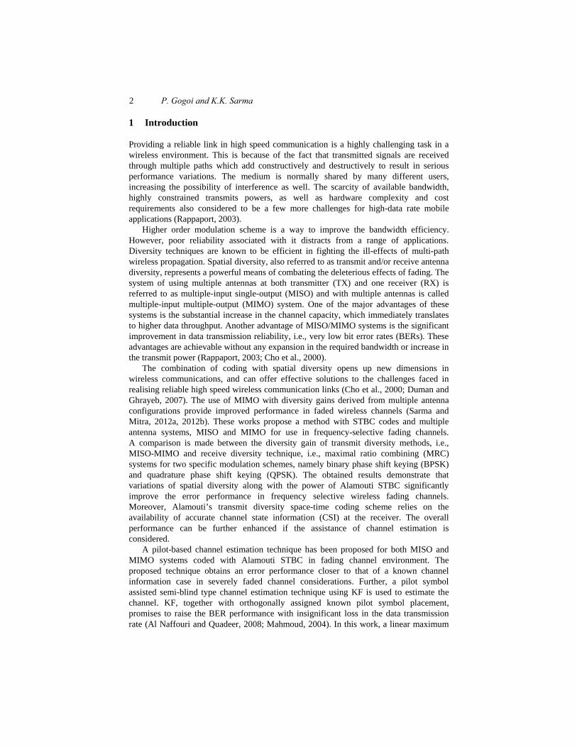
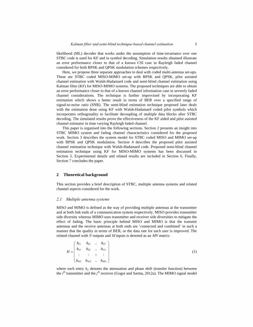
is described as ,r Hs n= + where r is the received vector of size N × 1, H is the channel matrix of size M × N, s is the transmitted vector of size M × 1, and n is the noise vector of size N × 1. Each noise element is typically modelled as independent identically distributed (i.i.d.) white Gaussian noise with variance Nt / (2 × SNR). A MIMO system with M transmit and N receive antennas has potentially full diversity (i.e., maximum diversity) gain equal to MN. Figures 1 and 2 show a MISO and MIMO system model with multiple transmitting and receiving antennas.
Figure 1 MISO system model with multiple transmitting and one receiving antenna
Figure 2 MIMO system model with multiple transmitting and one receiving antenna
2.2 Channel characteristics with multi-path Rayleigh fading
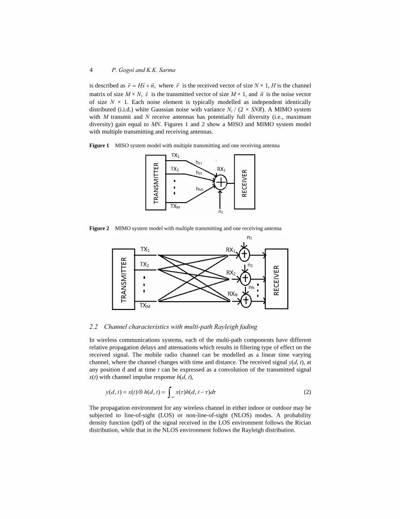
In wireless communications systems, each of the multi-path components have different relative propagation delays and attenuations which results in filtering type of effect on the received signal. The mobile radio channel can be modelled as a linear time varying channel, where the channel changes with time and distance. The received signal y(d, t), at any position d and at time t can be expressed as a convolution of the transmitted signal x(t) with channel impulse response h(d, t),
( , ) ( ) ( , ) ( ) ( , )t
y d t x t h d t x τ h d t τ dτ−∞
= ⊗ = −∫ (2)
The propagation environment for any wireless channel in either indoor or outdoor may be subjected to line-of-sight (LOS) or non-line-of-sight (NLOS) modes. A probability density function (pdf) of the signal received in the LOS environment follows the Rician distribution, while that in the NLOS environment follows the Rayleigh distribution.
Kalman filter and semi-blind technique-based channel estimation 5
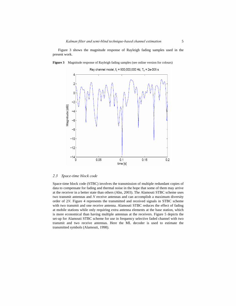
Figure 3 shows the magnitude response of Rayleigh fading samples used in the present work.
Figure 3 Magnitude response of Rayleigh fading samples (see online version for colours)
2.3 Space-time block code
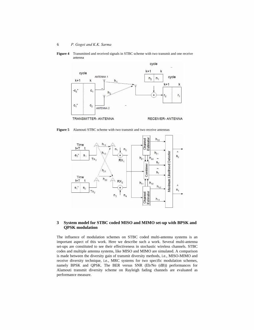
Space-time block code (STBC) involves the transmission of multiple redundant copies of data to compensate for fading and thermal noise in the hope that some of them may arrive at the receiver in a better state than others (Ahn, 2003). The Alamouti STBC scheme uses two transmit antennas and N receive antennas and can accomplish a maximum diversity order of 2N. Figure 4 represents the transmitted and received signals in STBC scheme with two transmit and one receive antenna. Alamouti STBC reduces the effect of fading at mobile stations while only requiring extra antenna elements at the base station, which is more economical than having multiple antennas at the receivers. Figure 5 depicts the set-up for Alamouti STBC scheme for use in frequency selective faded channel with two transmit and two receive antennas. Here the ML decoder is used to estimate the transmitted symbols (Alamouti, 1998).
6 P. Gogoi and K.K. Sarma
Figure 4 Transmitted and received signals in STBC scheme with two transmit and one receive antenna
Figure 5 Alamouti STBC scheme with two transmit and two receive antennas
3 System model for STBC coded MISO and MIMO set-up with BPSK and QPSK modulation
The influence of modulation schemes on STBC coded multi-antenna systems is an important aspect of this work. Here we describe such a work. Several multi-antenna set-ups are constituted to see their effectiveness in stochastic wireless channels. STBC codes and multiple antenna systems, like MISO and MIMO are simulated. A comparison is made between the diversity gain of transmit diversity methods, i.e., MISO-MIMO and receive diversity technique, i.e., MRC systems for two specific modulation schemes, namely BPSK and QPSK. The BER versus SNR (Eb/No (dB)) performances for Alamouti transmit diversity scheme on Rayleigh fading channels are evaluated as performance measure.
Kalman filter and semi-blind technique-based channel estimation 7
In the set up, a source generates the bits to be transmitted which are then fed to a digital modulator. Modulated symbols are again fed to the STBC encoder block, which maps the symbols according to a particular format, as discussed in Section 2.3. The symbols to be transmitted are then fed to the corresponding TX antennas, after transmitting the symbols they are then affected by the fading effects of wireless channels. At the receiver side, the reverse processes are carried out. In this work, Alamouti decoder equipped with ML decoding scheme is exploited for the symbol detection and decoding purposes. The decoded bits are again fed to the demodulators and transmitted bits with a little amount of error are tried to be recovered as received signal.
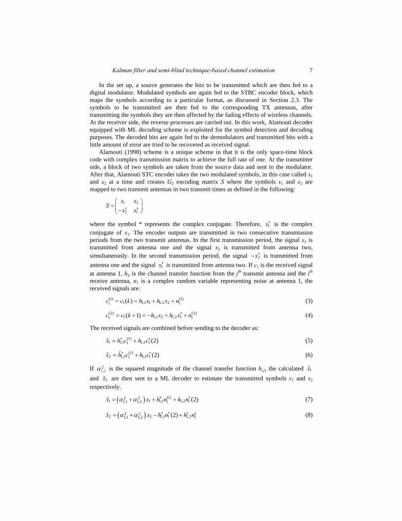
Alamouti (1998) scheme is a unique scheme in that it is the only space-time block code with complex transmission matrix to achieve the full rate of one. At the transmitter side, a block of two symbols are taken from the source data and sent to the modulator. After that, Alamouti STC encoder takes the two modulated symbols, in this case called x1 and x2 at a time and creates G2 encoding matrix S where the symbols x1 and x2 are mapped to two transmit antennas in two transmit times as defined in the following:
1 2* *2 1
x x
Sx x
⎛ ⎞=⎜ ⎟−⎝ ⎠
where the symbol * represents the complex conjugate. Therefore, *1x is the complex
conjugate of x1. The encoder outputs are transmitted in two consecutive transmission periods from the two transmit antennas. In the first transmission period, the signal x1 is transmitted from antenna one and the signal x2 is transmitted from antenna two, simultaneously. In the second transmission period, the signal *
2x− is transmitted from antenna one and the signal *
1x is transmitted from antenna two. If c1 is the received signal at antenna 1, hij is the channel transfer function from the jth transmit antenna and the ith receive antenna, n1 is a complex random variable representing noise at antenna 1, the received signals are:
(1) (1)1 1,1 1 1,2 21 1( )c c k h x h x n= = + + (3)
(2) (2)*1 1,1 2 1,2 11 1( 1)c c k h x h x n= + = − + + (4)
The received signals are combined before sending to the decoder as: (1)* *
1 1,1 1,2 11 (2)x h c h c= + (5)
(1)* *2 1,2 1,1 11 (2)x h c h c= + (6)
If 2,i jα is the squared magnitude of the channel transfer function hi,j, the calculated 1x
and 2x are then sent to a ML decoder to estimate the transmitted symbols x1 and x2 respectively.
( ) (1)2 2 * *1 1 1,1 1,2 11,1 1,2 1 (2)x x h n h n= + + +α α (7)
( )2 2 * * * 12 2 1,1 1 1,21,1 1,2 1(2)x x h n h n= + − +α α (8)

8 P. Gogoi and K.K. Sarma
3.1 Transmitted and received signals at Alamouti STBC-MISO system
In the simple transmit diversity technique proposed by Alamouti, the signals transmitted over a two symbol interval by antenna 1 and antenna 2 satisfy a special relationship. At time slot n and n + 1, antenna 1 transmits symbols x(n) and –x*(n + 1) respectively, while antenna 2 transmits symbols x(n + 1) and x*(n) respectively, where (.)* denotes complex conjugate. Assuming that the channels hi(n) from antenna i to the receiver at time n are uncorrelated, frequency-flat and time selective Rayleigh faded, the two consecutive received samples y1 and y2 can be expressed as given below. The received signal in the first time slot is obtained as,
( ) 11 1 1 2 2 1 1 2 1
2
xy h x h x n h h n
x⎛ ⎞
= + + = +⎜ ⎟⎝ ⎠
(9)
In the second time slot, the received signal is,
( )*2* *
2 1 2 2 1 2 1 2 2*1
––
xy h x h x n h h n
x⎛ ⎞
= + + = +⎜ ⎟⎝ ⎠
(10)
where y1, y2 are the received symbol on the first and second time slot respectively, h1 is the channel from first transmit antenna to receive antenna, h2 is the channel from second transmit antenna to receive antenna, x1, x2 are the transmitted symbols and n1, n2 are the zero mean i.i.d complex circular Gaussian noise with variance 2
wσ on respective time slots. The above equations can be represented in matrix notation as follows:
1 1 2 1 1* * * *2 2 1 2 2–
y h h x ny h h x n
⎛ ⎞ ⎛ ⎞⎛ ⎞ ⎛ ⎞= +⎜ ⎟ ⎜ ⎟⎜ ⎟ ⎜ ⎟
⎝ ⎠ ⎝ ⎠⎝ ⎠ ⎝ ⎠ (11)
The estimate of the transmitted symbols are,
( ) 11 1 1*
2 22
H Hx x nH H H
x nx
−⎛ ⎞ ⎛ ⎞ ⎛ ⎞⎜ ⎟ = +⎜ ⎟ ⎜ ⎟⎜ ⎟ ⎝ ⎠ ⎝ ⎠⎝ ⎠
(12)
where
1 2* *2 1–
h hH
h h⎛ ⎞
= ⎜ ⎟⎝ ⎠
(13)
3.2 Transmitted and received signals with Alamouti STBC-MIMO system
For the case of Alamouti STBC-MIMO system, the received signal in the first time slot is obtained as
1 111 12 11 1
1 121 22 22 2
h h xy nh h xy n
⎛ ⎞ ⎛ ⎞⎛ ⎞⎛ ⎞= +⎜ ⎟ ⎜ ⎟⎜ ⎟⎜ ⎟⎝ ⎠⎝ ⎠⎝ ⎠ ⎝ ⎠
(14)
Assuming that the channel remains constant for the second time slot, the received signal at this considered slot is,
Kalman filter and semi-blind technique-based channel estimation 9
2 1*11 12 21 2
2 2*21 22 12 2
–h hy nxh hy nx
⎛ ⎞ ⎛ ⎞⎛ ⎞⎛ ⎞= +⎜ ⎟ ⎜ ⎟⎜ ⎟⎜ ⎟⎝ ⎠⎝ ⎠⎝ ⎠ ⎝ ⎠
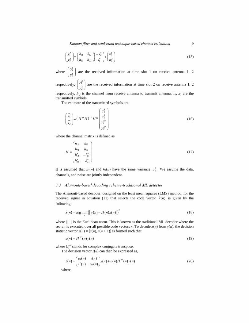
(15)
where 1112
yy
⎛ ⎞⎜ ⎟⎝ ⎠
are the received information at time slot 1 on receive antenna 1, 2
respectively, 2122
yy
⎛ ⎞⎜ ⎟⎝ ⎠
are the received information at time slot 2 on receive antenna 1, 2
respectively, hi,j is the channel from receive antenna to transmit antenna, x1, x2 are the transmitted symbols.
The estimate of the transmitted symbols are,
( )
11111 22*122*2
H H
yx y
H H Hyxy
−
⎛ ⎞⎜ ⎟⎛ ⎞ ⎜ ⎟⎜ ⎟ = ⎜ ⎟⎜ ⎟
⎝ ⎠ ⎜ ⎟⎜ ⎟⎝ ⎠
(16)
where the channel matrix is defined as
11 12
21 22* *12 11* *22 21
––
h hh h
Hh hh h
⎛ ⎞⎜ ⎟⎜ ⎟=⎜ ⎟⎜ ⎟⎝ ⎠
(17)
It is assumed that h1(n) and h2(n) have the same variance 2.hσ We assume the data, channels, and noise are jointly independent.
3.3 Alamouti-based decoding scheme-traditional ML detector
The Alamouti-based decoder, designed on the least mean squares (LMS) method, for the received signal in equation (11) that selects the code vector ˆ( )x n is given by the following:
( )2ˆ( ) arg min ( ) – ( ) ( )x
x n y n H n x n= (18)
where || . || is the Euclidean norm. This is known as the traditional ML decoder where the search is executed over all possible code vectors x. To decode x(n) from y(n), the decision statistic vector z(n) = [z(n), z(n + 1)] is formed such that
( ) ( ) ( )Hz n H n y n= (19)
where (.)H stands for complex conjugate transpose. The decision vector z(n) can then be expressed as,
1*
2
( ) ( )( ) ( ) ( ) ( ) ( )
( ) ( )Hρ n n
z n x n n n H n y nn ρ n
⎛ ⎞= +⎜ ⎟⎝ ⎠
εε
(20)
where,
10 P. Gogoi and K.K. Sarma
2 21 1 2( ) ( ) ( 1) ,ρ n h n h n= + + (21)
2 22 1 2( ) ( 1) ( ) ,ρ n h n h n= + + (22)
* *1 2 1 2( ) ( ) ( ) – ( 1) ( 1),n h n h n h n h n= + +ε (23)
3.4 Received signals at Alamouti STBC-MRC system
On the receive antenna, the received signal is,
i i iy h x n= + (24)
where yi is the received symbol on the ith receive antenna, hi is the channel on the ith receive antenna, x is the transmitted symbol and ni is the noise on ith receive antenna. The equalised symbol is,
ˆ H H H H H H H Hx h y h h h hx h h h n h h x h n h h= = + = + (25)
where
2
1
NH
ii
h h h=
=∑ (26)
is the sum of the channel powers across all the receive antennas.
4 Proposed pilot assisted channel estimation technique with Walsh-Hadamard code
STBC and space time trellis code (STTC) are designed for coherent detection where channel estimation is necessary. Considerable literature addresses the channel estimation issues for MIMO systems, ranging from standard training-based techniques that rely on pilot symbols in the data stream to blind which does not require pilot sequences and semi-blind (Gogoi and Sarma, 2012b) estimation where observations corresponding to data and pilot are used jointly. Non-coherent detection schemes based on soft computing tools which do not require CSI have also been reported in successive works (Gogoi and Sarma, 2012c, 2012d).
Although these methods avoid the need for channel estimation, they often suffer from problems such as error propagation. Training-based methods provide improved results of channel estimation at the receiver. Pure training-based schemes can be considered as an advantage when an accurate and reliable MIMO channel needs to be obtained. However, this could also be a disadvantage when bandwidth efficiency is required. This is because pure training-based schemes reduce the bandwidth efficiency considerably (Sarma and Mitra, 2012a) due to the use of a long training sequence which is necessarily needed in order to obtain a reliable MIMO channel estimate. Because of the computation complexity of blind and semi-blind methods, many wireless communication systems still use pilot sequences to estimate the channel parameters at the receiver side. These reasons motivated Tarokh et al. (1998) to propose a new joint detection scheme for transmit diversity with no CSI. These reasons also motivated authors in Tarokh et al. (1999) to

Kalman filter and semi-blind technique-based channel estimation 11
propose a new channel estimation algorithm that uses pilot sequences and minimum square error (MSE) to estimate the channel parameters. These two methods have the advantages of low computation, thus becoming the base of the research in this thesis.
The transmitter and receiver structure of STBC system with channel estimation technique is shown in Figure 6. The channel estimation is used here to estimate the time-varying channel and decode the symbols after estimation. Channel estimation is necessary here as we have considered unknown CSI at the RX for the work in this part. STBC decoding is also based on Alamouti scheme here, with ML decoding. A combiner is used at the next stage after the estimator and decoder block, preceded by the PSK demodulator. The two pilot assisted channel estimation techniques proposed here are separately described under the following sections.
Figure 6 Transmitter and receiver structure of STBC system with channel estimation
4.1 System model for the pilot assisted channel estimation technique
The decoding of space-time codes requires the knowledge of CSI at the receiver, which is usually difficult to obtain. All space-time schemes assume ideal channel state information. However, channel parameters are normally not known in practice due to changing environments and thus need to be estimated. A channel estimator extracts from the received signal an approximation to the fade coefficients during each data frame. This can be done using training or pilot symbols or sequences to estimate the channels from each of the transmit antennas to each receive antenna. The advantage of pilot symbol insertion is that it neither requires a complex signal process nor does it increase the peak factor of the modulated carrier. One method of MIMO channel estimation is to turn off all transmit antennas apart from antenna i at some time instant and to send a pilot signal using antenna i. The fade coefficients hi,j are then estimated for all j. This procedure is repeated for all i until all the coefficients are estimated. A second method of estimation is

12 P. Gogoi and K.K. Sarma
to send orthogonal sequence of signals for pilot signals, one from each transmit antenna. The use of the orthogonal pilot sequence can ensure a full rank of the coefficient matrix.
In this work, a channel estimator is designed with assistance from pilot symbols transmitted along with actual bits. The arrangement and properties of pilots for multi-antenna structures are certainly different from that of single-antenna cases. The amount of total pilot symbols will be multiplied by the number of transmitting antennas, it means that more pilots are necessary for MIMO architecture. Secondly, pilot blocks transmitted on different antennas must be orthogonal to each other to facilitate the decoupling of multiple mixed data blocks after STBC decoding, then the separated symbols could be correctly detected by ML detector individually to recover the original transmitted signals. Thirdly, how to assign the pilot blocks on two transmitting branches while the inter-transmitter antenna interference. If the training/pilot sequence is treated by the modulator and STBC encoder in the same rules as for user data, the coefficient matrix is always non-singular because of the orthogonality of STBC codes of the user data. This is obviously a convenience, which takes the advantage of space-time block code systems (Tarokh et al., 1998).
5 Proposed semi-blind channel estimation technique using KF for MISO-MIMO systems
The work is next extended to semi-blind approach of channel estimation technique using KF. KF with the aid of pilot symbols promises to raise the BER performance in a wireless environment with an insignificant loss in the data transmission rate. It is an efficient recursive algorithm which estimates the state of a dynamic system from a series of noisy measurements. KF estimation is quite common in the literature related to wireless systems. In Song (2003) and Ling (2006) the KF is used for tracking MIMO channels based on a low order autoregressive (AR) model. However, exact modelling of fast time varying channel with a low order model is impossible since the AR functions are irrational and higher order statistics are needed. The following aspects are important.
5.1 Process to be estimated
The KF addresses the general problem of trying to estimate the state x ∈ ℜn of a discrete-time controlled process that is governed by the linear stochastic difference equation (Kalman, 1960)
–1 –1 –1,j j j jx Ax Bu w= + + (27)
with a measurement z ∈ ℜm that is
.j j jz Hx v= + (28)
The random variables wj and vj represent the process and measurement noise respectively. They are assumed to be independent of each other, white, and with normal probability distributions
( ) ~ (0, ),p w N Q (29)
( ) ~ (0, ).p v N R (30)
Kalman filter and semi-blind technique-based channel estimation 13
In practice, the process noise covariance Q and measurement noise covariance R matrices might change with each time step or measurement (Teo, 2004). The n × n matrix A in the difference equation relates the state at the previous time step j – 1 to the state j at the current step, in the absence of either a driving function or process noise. The n × l matrix B relates the optional control input u ∈ ℜl to the state x. The m × n matrix H in the measurement equation relates the state to the measurement zj.
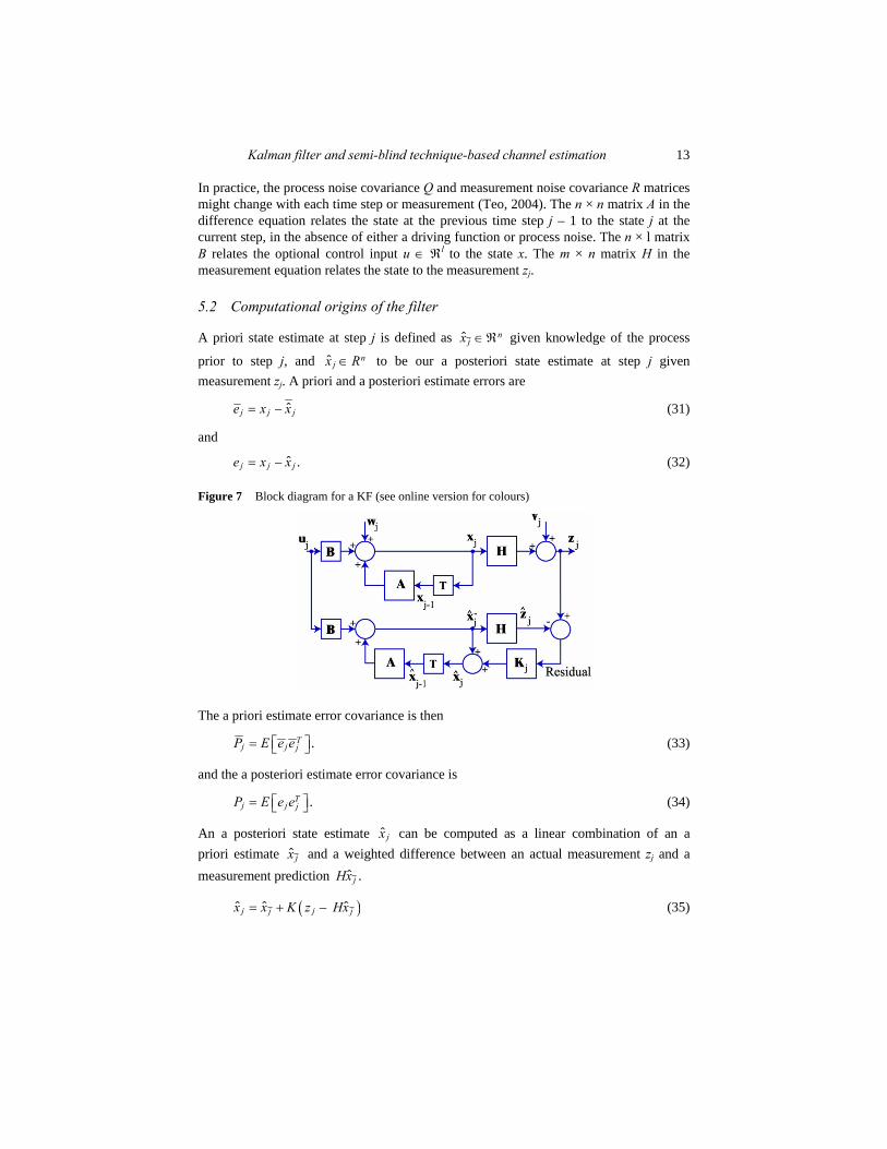
5.2 Computational origins of the filter
A priori state estimate at step j is defined as ˆ njx ∈ℜ given knowledge of the process
prior to step j, and ˆ njx R∈ to be our a posteriori state estimate at step j given
measurement zj. A priori and a posteriori estimate errors are
ˆ–j j je x x= (31)
and
ˆ– .j j je x x= (32)
Figure 7 Block diagram for a KF (see online version for colours)
The a priori estimate error covariance is then
.Tj j jP E e e= ⎡ ⎤⎣ ⎦ (33)
and the a posteriori estimate error covariance is
.Tj j jP E e e= ⎡ ⎤⎣ ⎦ (34)
An a posteriori state estimate ˆ jx can be computed as a linear combination of an a priori estimate ˆ jx and a weighted difference between an actual measurement zj and a measurement prediction ˆ .jHx
( )ˆ ˆ ˆ– j jj jx x K z Hx= + (35)
14 P. Gogoi and K.K. Sarma
The difference ˆ–j jz Hx is called the measurement innovation, or the residual. The residual reflects the discrepancy between the predicted measurement ˆ jHx and the actual measurement zj. A residual of zero means that the two are in complete agreement. The n × m matrix K is chosen to be the gain or blending factor that minimises the a posteriori error covariance.
( )–1T Tj j jK P H HP H R= + (36)
( )T Tj j jK P H HP H R= + (37)
The KF estimates a process by using a form of feedback control: the filter estimates the process state at some time and then obtains feedback in the form of noisy measurements. As such, the equations for the KF fall into two groups: time update equations and measurement update equations. The time update equations are responsible for projecting forward (in time) the current state and error covariance estimates to obtain the a priori estimates for the next time step. The measurement update equations are responsible for the feedback, i.e., for incorporating a new measurement into the a priori estimate to obtain an improved a posteriori estimate.
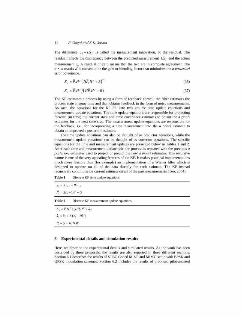
The time update equations can also be thought of as predictor equations, while the measurement update equations can be thought of as corrector equations. The specific equations for the time and measurement updates are presented below in Tables 1 and 2. After each time and measurement update pair, the process is repeated with the previous a posteriori estimates used to project or predict the new a priori estimates. This recursive nature is one of the very appealing features of the KF. It makes practical implementations much more feasible than (for example) an implementation of a Wiener filter which is designed to operate on all of the data directly for each estimate. The KF instead recursively conditions the current estimate on all of the past measurements (Teo, 2004). Table 1 Discrete KF time update equations
1 1ˆ ˆ j jjx Ax Bu− −= +
1 Tj jP AP A Q= − +
Table 2 Discrete KF measurement update equations
/ ( )T Tj j jK P H HP H R= +
ˆ ˆ ˆ( – )j jj jx x K z Hx= +
( )j j jP I K H P= −
6 Experimental details and simulation results
Here, we describe the experimental details and simulated results. As the work has been described by three proposals, the results are also reported in three different sections. Section 6.1 describes the results of STBC Coded MISO and MIMO setup with BPSK and QPSK modulation schemes. Section 6.2 includes the results of proposed pilot-assisted

Kalman filter and semi-blind technique-based channel estimation 15
channel estimation technique for MISO and MIMO architecture. Section 6.3 describes the results of pilot assisted channel estimation technique using KF.
6.1 Experimental results of STBC coded MISO and MIMO set-up with BPSK and QPSK modulation
In this work, it is assumed that the channel experienced by each transmit antenna is independent from the channel experienced by other transmit antennas where the information symbols x(n) are transmitted using Alamouti’s space time block encoder. For the transmit antenna, each transmitted symbol gets multiplied by a randomly varying complex number hi,j as shown in equation (7). As the channel under consideration is a Rayleigh channel, the real and imaginary parts of hi,j are Gaussian distributed having mean , 0i jhμ = and variance 2
,0.5.
i jhσ = The channel experienced between each transmit
to the receive antenna is randomly varying in time. However, the channel is assumed to remain constant over two time slots.
In the set up, the total power transmitted from all transmitting antennas is the same for all cases. The fading channel used in the simulation is Rayleigh fading channel and modulation schemes used are BPSK and QPSK respectively. The transmit symbols are uniformly distributed based on M-PSK constellations, and transmitted across all transmit antennas. The SNR values are taken to be from –10 to 10 dB and 1,000 bit blocks are transmitted. For the MRC simulation, we have two receive antennas and one transmit antenna. The channel experienced by each receive antenna is randomly varying in time. For the receive antenna, each transmitted symbol gets multiplied by a randomly varying complex number. The channel experience by each receive antenna is independent from the channel experienced by other receive antennas. The components of the system and channel parameters are summarised in Table 3. Table 3 MISO/MIMO system, STBC coding and channel parameters
Parameters Adopted values Multiple antenna system MISO and MIMO TX antenna TX = 2 RX antenna RX = 1, 2 respectively Modulation format BPSK and QPSK SNR [–10:10] dB Frequency selective channel Rayleigh faded channel Channel state information Perfectly known at RX Decoding scheme Alamouti
16 P. Gogoi and K.K. Sarma
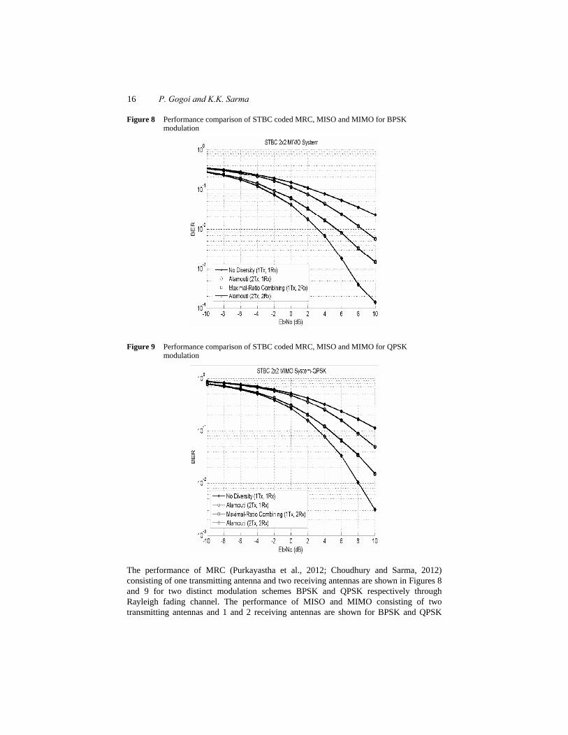
Figure 8 Performance comparison of STBC coded MRC, MISO and MIMO for BPSK modulation
Figure 9 Performance comparison of STBC coded MRC, MISO and MIMO for QPSK modulation
The performance of MRC (Purkayastha et al., 2012; Choudhury and Sarma, 2012) consisting of one transmitting antenna and two receiving antennas are shown in Figures 8 and 9 for two distinct modulation schemes BPSK and QPSK respectively through Rayleigh fading channel. The performance of MISO and MIMO consisting of two transmitting antennas and 1 and 2 receiving antennas are shown for BPSK and QPSK
Kalman filter and semi-blind technique-based channel estimation 17
respectively. It is observed that enhancement in performance is clear when STBC coding schemes are used in MIMO scheme, as compared to MISO and MRC schemes over the Rayleigh faded channel. MISO scheme shows a degraded result than the MRC scheme for both the cases.
6.2 Experimental results of pilot assisted channel estimation technique
Here we describe the experimental results of proposed pilot-assisted channel estimation technique for MISO and MIMO architecture by assigning known pilot symbols orthogonally between different transmitting antennas. The mixed transmitted signals could be completely separated at the receiver end due to the orthogonal property of pilot blocks. The pilot symbols are inserted to the transmission bits in block by block pattern for a particular frame length. The pilots are generated using Walsh Hadamard coding, to incorporate orthogonal pilot sets per frame length. The orthogonality nature of the pilots are exploited during the ML detector estimation. The CSI is unknown in this case.
An orthogonal pilot matrix in the context of MIMO FIR channels can be constructed by employing the Walsh Hadamard scheme. It is an algorithm that generates statistically unique sets of numbers for use in encryption and cellular communications. It is also known as ‘pseudo-random noise codes’, Walsh codes are used in direct sequence spread spectrum (DSSS) systems. They are also used in frequency hopping spread spectrum (FHSS) systems to select the target frequency for the next hop. The orthogonal pilot sequence is constructed from Walsh-Hadamard matrices by employing the scheme as given below. If perfectly synchronised with respect to each other, W-H codes are perfectly orthogonal. It means that, Walsh-Hadamard are optimal codes to avoid interference among users in the link from base station to terminals. The simplest matrix of two orthogonal Walsh-Hadamard sequences is:
1 11 .
1 1C ⎛ ⎞
= ⎜ ⎟−⎝ ⎠
The code of user 1 is the first column, i.e., (1, 1), the code of user 2 is the second column, i.e., (1, –1). Clearly (1, 1) is orthogonal to (1, –1). This matrix can be extended using a recursive technique. For 2n users, the matrix is found from the code matrix for 2(n – 1) users, according to
( 1) ( 1).
( 1) ( 1)C n C n
CnC n C n
− −⎛ ⎞= ⎜ ⎟− − −⎝ ⎠
Walsh-Hadamard sequences are rows of the Walsh-Hadamard matrix and the 0th Walsh-Hadamard sequence is an all-one sequence.
In this section, we show the simulation results for the performance of STBC on Rayleigh fading channels. In the simulation, the receivers do not know the CSI and have to estimate them using the joint channel estimation and data detection scheme. The performances of the BER for STBC with different numbers of transmit and receive antennas are shown in different figures depending on the modulation scheme used and number of transmit antennas. The simulation results for the performance of STBC with estimated channel parameters are recorded for the purpose of plotting and comparing with the performance of STBC with known channel parameters at the receiver.

18 P. Gogoi and K.K. Sarma
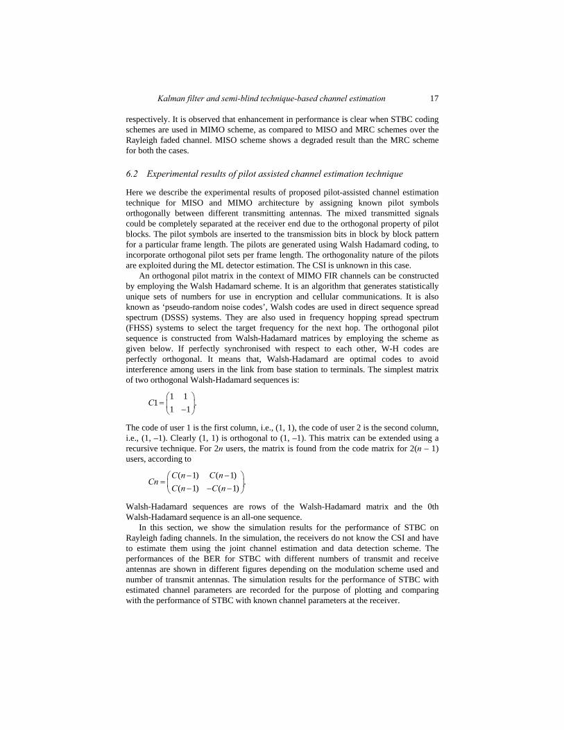
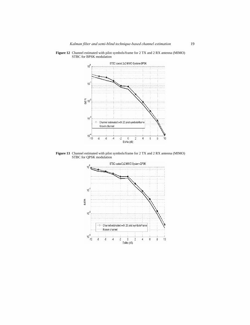
Figures 10 to 13 show the BER result for channel estimated with 20 pilot bits per frame and for known channel estimation for the case of Alamouti STBC coded MISO and MIMO set-up. The estimation is carried out for both BPSK and QPSK modulation. Estimation results show that the best results are obtained with the MIMO channels and BPSK modulation scheme (BER 10–4 at 10 dB SNR value).
Figure 10 Channel estimated with pilot symbols/frame for 2 TX and 1 RX antenna (MISO) STBC for BPSK modulation
Figure 11 Channel estimated with pilot symbols/frame for 2 TX and 1 RX antenna (MISO) STBC for QPSK modulation
Kalman filter and semi-blind technique-based channel estimation 19
Figure 12 Channel estimated with pilot symbols/frame for 2 TX and 2 RX antenna (MIMO) STBC for BPSK modulation
Figure 13 Channel estimated with pilot symbols/frame for 2 TX and 2 RX antenna (MIMO) STBC for QPSK modulation
20 P. Gogoi and K.K. Sarma
6.3 Experimental results of pilot assisted channel estimation technique using KF
In this work, a linear ML decoder that works under the assumption of time-in-variance over one STBC is used for KF and in symbol decoding.
The state space equations for tracking the MIMO channel can be expressed as:
( 1) ( ) ( )h t A t h t+ = (38)
( ) ( ) ( ) ( )s t C t h t v t= + (39)
where h is the channel tap, A is a time-varying transition matrix, C is the observation matrix and v is the measurement noise vector. A first-order AR model provides a sufficient model for time varying channels. Therefore, A can be a diagonal matrix of autoregressive model factor α, where
*( 1) ( )ij ijE h t h tα = + ∗⎡ ⎤⎣ ⎦ (40)
The KF equations for MIMO channel are divided into two parts. First part is the predictor:
( 1 | ) ( ) ( | )h t t A t h t t+ = (41)
*( 1| ) ( ) ( | ) ( )TP t t A t P t t A t+ = (42)
( ) ( ) ( ) ( 1 | )ε t s t C t h t t= − + (43)
[ ] 1* *( ) ( 1 | ) ( ) ( ) ( 1 | ) ( )T TvK t P t t C t C t P t t C t R −
= + + + (44)
and the second part is the update:
( 1 | 1) ( 1 | ) ( ) ( )h t t h t t K t ε t+ + = + + (45)
[ ]( 1| 1) ( ) ( ) ( 1 | )P t t I K t C t P t t+ + = − + (46)
where Rv = βI and β is a covariance of the noise vector v. The K matrix is called the Kalman gain and the P matrix is called the estimation error covariance. The first term in the state estimate ( )h in equation (45) is used to derive the state estimate at time t + 1. The state estimate would propagate in time just like the state vector in the system model. The second term in equation (45) is called the correction term and it represents the amount by which to correct the propagated state estimate due to the measurement.
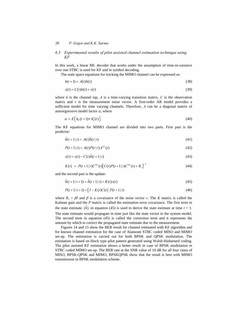
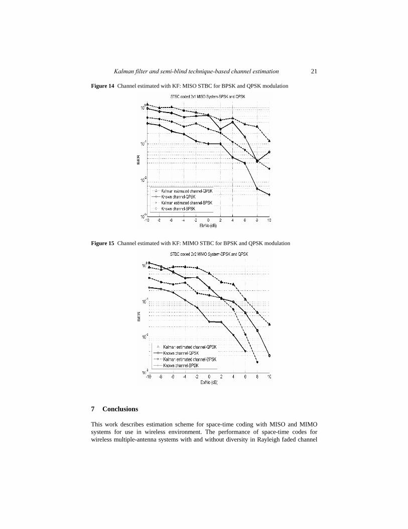
Figures 14 and 15 show the BER result for channel estimated with KF algorithm and for known channel estimation for the case of Alamouti STBC coded MISO and MIMO set-up. The estimation is carried out for both BPSK and QPSK modulation. The estimation is based on block type pilot pattern generated using Walsh-Hadamard coding. The pilot assisted KF estimation shows a better result in case of BPSK modulation in STBC coded MIMO set-up. The BER rate at the SNR value of 10 dB for all four cases of MISO, BPSK-QPSK and MIMO, BPSKQPSK show that the result is best with MIMO transmission in BPSK modulation scheme.
Kalman filter and semi-blind technique-based channel estimation 21
Figure 14 Channel estimated with KF: MISO STBC for BPSK and QPSK modulation
Figure 15 Channel estimated with KF: MIMO STBC for BPSK and QPSK modulation
7 Conclusions
This work describes estimation scheme for space-time coding with MISO and MIMO systems for use in wireless environment. The performance of space-time codes for wireless multiple-antenna systems with and without diversity in Rayleigh faded channel
22 P. Gogoi and K.K. Sarma
has been studied earlier. Since the knowledge of the channel with perfect CSI is unattainable for Alamouti STBC over Rayleigh fading channel which makes the error performance to degrade, a pilot-based channel estimation technique is proposed to obtain an error free transmission without the knowledge of the faded channel in hand. Moreover, a semi-blind estimation technique proposed later deals with the estimation using KF with Walsh-Hadamard coded pilot symbols which incorporates orthogonality to facilitate decoupling of multiple data blocks after STBC decoding. The simulated results prove the effectiveness of the pilot assisted channel estimator techniques described here over time-varying Rayleigh faded channel. The work can be further extended to higher order multiple antenna systems with higher modulation schemes for use in real time channel scenario.
References Ahn, K. (2003) ‘Decision feedback detection for space time block coding over time-selective
fading channels’, Proceedings of 14th IEEE International Symposium on Personal, Indoor and Mobile Radio Communication, Vol. 2, pp.1983–1987.
Al Naffouri, T.Y. and Quadeer, A.A. (2008) ‘A forward-backward Kalman filter-based STBC MIMO OFDM receiver’, EURASIP Journal on Advances in Signal Processing, Vol. 3, No. 2, pp.246–249.
Alamouti, S.M. (1998) ‘A simple transmit diversity technique for wireless communications’, IEEE Journal on Selected Areas in Communications, Vol. 16, No. 8, pp.1451–1458.
Cho, Y.S., Kim, J., Yang, W.Y. and Kang, C. (2000) Wireless Communications – Principles and Practice, Pearson Education, New Delhi.
Choudhury, A. and Sarma, K.K. (2012) ‘Coding and adaptive equalization assisted MRC in wireless channels’, Proceedings of 2nd National IEEE Conference on Emerging Trends and Applications in Computer Science (NCETACS), hillong, India, Vol. 2, pp.1–6.
Duman, T.M. and Ghrayeb, A. (2007) Coding for MIMO Communication System, 2nd ed., Wiley India, New Delhi.
Gogoi, P. and Sarma, K.K. (2012a) ‘Artificial neural network based channel estimation technique for STBC coded MIMO system over Rayleigh fading channel’, Proceedings of CUBE 2012, Pune, India, pp.294–298.
Gogoi, P. and Sarma, K.K. (2012b) ‘Channel estimation technique for STBC coded MIMO system with multiple ANN blocks’, International Journal of Computer Applications (IJCA), Vol. 50, No. 13, pp.10–14.
Gogoi, P. and Sarma, K.K. (2012c) ‘Hybrid channel estimator with recurrent neural networks for space time block code over Rayleigh faded channels’, Book chapter in Latest Advances In Information Science, Circuits and Systems, Vol. 4, pp.41–48, WSEAS Press.
Gogoi, P. and Sarma, K.K. (2012d) ‘Pilot assisted channel estimation technique for Alamouti STBC-MISO and MIMO set-up with BPSK and QPSK modulation’, Proceedings of 3rd IEEE National Conference on Emerging Trends and Applications in Computer Science (NCETACS), Shillong, India, Vol. 3, pp.246–252.
Kalman, R.E. (1960) ‘A new approach to linear filtering and prediction problems’, Journal of Basic Engineering, Vol. 82, No. 1, pp.35–45.
Ling, W. (2006) ‘Kalman filter channel estimation based on comb-type pilot in time-varying channel’, Proceedings of International Conference on Wireless Communications, Networking and Mobile Computing, Vol. 5, pp.1–3.
Mahmoud, H. (2004) ‘Kalman filter channel estimation based on comb type pilots for OFDM system in time and frequency selective fading environments’, Proceedings of International Conference on Communications, Computers and Applications, pp.59–64.

Kalman filter and semi-blind technique-based channel estimation 23
Purkayastha, G.K. and Sarma, K.K. (2012) ‘Maximal ratio combining using ANN-assisted equalisation in wireless channels’, Proceedings of 2nd National IEEE Conference on Computational Intelligence and Signal Processing (CISP), Guwahati, India, pp.36–39.
Rappaport, T.S. (2003) Wireless Communications – Principles and Practice, 2nd ed., Pearson Education, New Delhi.
Sarma, K.K. and Mitra, A. (2012a) ‘Estimation of MIMO channels using complex time delay fully recurrent neural network’, Proceedings of 2nd National IEEE Conference on Emerging Trends and Applications in Computer Science, Shillong, India, pp.1–5.
Sarma, K.K. and Mitra, A. (2012b) ‘Estimation of MIMO wireless channels using artificial neural networks’, Book Chapter in Cross-disciplinary Applications of Artificial Intelligence and Pattern Recognition: Advancing Technologies, pp.509–543, IGI Publications, USA.
Song, K.J. (2003) ‘Novel channel estimation algorithm using Kalman filter for Ds-Cdma Rayleigh fading channel’, Proceedings of IEEE International Conference on Acoustics, Speech, and Signal Processing, Vol. 25, pp.429–432.
Tarokh, V., Jafarkhani, H. and Calderbank, A.R. (1999) ‘Space time block codes from orthogonal designs’, IEEE Transactions on Information Theory, Vol. 45, No. 5, pp.744–765.
Tarokh, V., Seshadri, N. and Calderbank, A.R. (1998) ‘Spacetime codes for high data rate wireless communication: performance analysis and code construction’, IEEE Transactions on Information Theory, Vol. 44, No. 2, pp.744–765.
Teo, K. (2004) ‘Kalman filter-based channel estimation for space-time block code’, 47th Midwest Symposium on Circuits and Systems, Vol. 2, pp.669–672.