paris 2020 c2-c6-322 s. cherevatskiy1 2, h. …
TRANSCRIPT

Grid Forming Energy Storage System addresses challenges of grids with high penetration of renewables (A case study)
S. CHEREVATSKIY1, S. SPROUL1, S. ZABIHI1,
R. KORTE2, H. KLINGENBERG2, B. BUCHHOLZ3, A. OUDALOV4 1,3,4ABB Power Grids, 2ElectraNet
1,2Australia, 3Germany, 4Switzerland SUMMARY The Australian National Electricity Market (NEM) has experienced a dramatic transformation due to rapid uptake of both small-scale and large-scale renewable energy generation, and the closure of multiple coal power plants. Many power systems around the world are undergoing a similar transition as they move away from fossil-fuel or nuclear generation. The Australian state of South Australia epitomises this transformation as the share of renewable energy generation in the state grew from 14% in 2009 to 51% in 2018 [2], dominated by wind power. Combined with limited interstate transmission capacity, the state's power system has experienced instantaneous penetration from wind generation in excess of 140% - the highest for any major power system in the world [3]. This high presence of non-synchronous generation reduces the system strength that has traditionally been provided by synchronous generators. The Dalrymple Battery Energy Storage System (BESS) (also known as ESCRI-SA) is a 30 MVA / 8 MWh Grid Forming BESS with microgrid automation. It was installed on the lower Yorke Peninsula in 2018, near the end of a long 132 kV single-circuit radial feeder. The Dalrymple BESS is the first (and currently only) large scale, Grid Forming BESS connected to the NEM and is built on Virtual Synchronous Generator technology, which strengthens the grid by replicating the behaviour and performance of a synchronous machine, providing synthetic inertia and high fault current to allow higher levels of renewables to connect and operate [4]. The system also provides reliability and flexibility services such as fast power injection, seamless islanding and black start of the local distribution network. When faults occur on the upstream feeder, the system seamlessly islands in co-ordination with the nearby 91 MW Wattle Point Wind Farm and distributed solar PV, to continue operating a local islanded power system to ensure continuity of supply to the local customers. This makes the Dalrymple BESS more than an energy storage system, but the largest autonomous microgrid in the world.
Paris 2020
C2-C6-322

2
The project’s results and operation has demonstrated for the first time on the NEM the critical role Grid Forming converters, as opposed to grid following converters, can play in strengthening the grid and enabling high renewable targets to be met. In addition to this, the Dalrymple BESS offers competitive market services to the NEM, providing a commercial return to the operator, which isn’t possible currently with comparable power system support technology such as synchronous condensers. This paper outlines the commercial structure and market context, then explores the design and functionality of the Virtual Synchronous Generator technology. The paper then highlights the key technical benefits Grid-Forming Converters offer and concludes with key validated performance results based on commissioning data and the first months of operation of the Dalrymple BESS. The Dalrymple BESS addresses an array of challenges and reinforces how BESS with Virtual Synchronous Generator technology can provide multiple value streams to utilities, consumers and the broader electricity market, as well as enable large scale power systems to operate at higher levels of renewable energy than previously possible.
KEYWORDS
Virtual Synchronous Generator – Virtual Synchronous Machine – Grid Forming Converter Grid Forming Inverter – Battery Energy Storage – BESS – Synthetic Inertia – Islanding – Black Start
Microgrid – Renewable Energy – Ancillary Services – Power System Strength – Fault Current

3
1. INTRODUCTION The Lower Yorke Peninsula, a 33 kV medium voltage network at the end of a long radial 132 kV feeder, was selected as the host site for the Dalrymple Grid Forming Battery Energy Storage System (GF-BESS) due to the multiple value streams it presented. The long radial 132 kV line connects the 91 MW Wattle Point Wind Farm to the NEM and also serves local towns in the area. The region is exposed to outages when lightning strikes interrupt the single supply line. The site allowed regulated benefits to be harnessed by providing back up to towns in the area, by seamlessly transitioning to an island with the wind farm when upstream outages occur, reducing unserved energy for ElectraNet’s customers. While this network is interconnected with the NEM, in non-islanded operation, the system provides both synthetic inertia and fast active power injection to enhance the reliability of South Australia’s network and support power system operation with the high penetration of wind in the state. The site also allowed for management of the loading on interstate interconnectors to further assist the stability and reliability of the state’s power system. Along with these technical benefits, commercial value would be extracted by having access to the national electricity wholesale and frequency control ancillary services (FCAS) markets. Figure 1 (left) shows the location of the GF-BESS on the Yorke Peninsula with the 91 MW Wattle Point wind farm to the south. A single line diagram of the system is shown on the right.
Figure 1: Left – Dalrymple BESS, existing transmission assets and Wattle Point Wind Farm at the tip of the peninsula [5]; Right – Simplified single line diagram Dalrymple BESS and microgrid
2. COMMERCIAL STRUCTURE
2.1. Ownership
A unique ownership structure was established to extract regulated and competitive market services from the Dalrymple BESS within the current regulatory framework. The system is owned and maintained by ElectraNet, with the operation of the BESS leased to AGL, a generator and retailer, for twelve years. The ownership and operation model of the Dalrymple BESS project is shown in Figure 2 on the left and a photograph of the BESS building on the right [5].
Figure 2: Left – Commercial model of ESCRI-SA project [7]; Right – Aerial photograph of Dalrymple BESS
132 kV
33 kV
Market Services
FCAS Energy arbitrage
Regulated Services
Reduce unserved energy Fast frequency response
Dalrymple BESS
30MW/8MWh Load/DER
91MW Wind Farm
Dalrymple substation
NEM

4
As shown, grants from ARENA provided partial funding for the project. ElectraNet provides regulated services through the ownership of the Dalrymple BESS while AGL operates in competitive markets with the BESS through the lease arrangement. The payments are shown with red arrows and the benefits are illustrated with green arrows.
2.2. Revenue Streams
The revenue streams for the Dalrymple BESS project are from the provision of synthetic inertia, reduction of Unserved Energy, FCAS markets and energy arbitrage. There are a number of other services; black start, fault current provision, voltage regulation, fast active power injection for the system integrity protection scheme (SIPS), power factor regulation and DER curtailment, that are not yet monetized either by choice or because there is no mechanism to do so under the current market and regulatory frameworks. The revenue streams currently accessed, as mentioned, are:
• The inertial response from the GF-BESS reduces constraints on the Heywood interconnector, improving utilization of the single interstate AC interconnection. This is achieved through a contribution of 200 MWs equivalent of synchronous inertia provided by the synthetic inertia of the GF-BESS into the South Australian power system [5].
• Reduction of Unserved Energy to the Dalrymple region following loss of supply, involving islanding of the GF-BESS with the local load, while keeping the Wattle Point Wind Farm at reduced output and local rooftop PV in service, until connection to the NEM is restored. In the first six months of operation the GF-BESS has reduced the loss of supply from approximately 8 hours to 30 minutes [5].
• Market trading of electricity in the NEM through the provision of FCAS services and energy arbitrage. In the first six months of operation the GF-BESS had earnt AU$1.13 million from FCAS markets [5].
3. FUNCTIONALITY All of the Dalrymple BESS functionality is enabled by the high power, Grid Forming Converter platform, and its control system consisting of two levels: primary and secondary. The primary control is implemented on the converters while the secondary control is housed in the distributed controllers.
At the heart of the primary control is the Virtual Synchronous Generator (VSG) – a high power Grid Forming converter combining synthetic inertia, synthetic impedance, frequency governor, synchronous generator rotor flux model and an automatic voltage regulator (AVR). Its control diagram is shown in Figure 3.
Figure 3: ABB Virtual Synchronous Generator primary control model [8]

5
These control components work in concert to make the VSG behave closely to a synchronous generator during both steady-state and transient conditions [8] and enable advanced performance in stand-alone operation, when paralleling with other voltage and/or current sources or when grid connected. The converter always operates as a voltage source which enables seamless transition into and out of islanded operation, and the VSG layer allows tuning and flexibility for effective integration to the power system at its point of connection.
The secondary control (not shown in the figure), the overarching and distributed e-mesh™ control, is integrated on top of the primary control and houses the majority of the project specific automation and functional logic.
Together, both control layers provide the following key functionality and innovative features relative to other generation and energy storage installations:
• converters with Grid Forming capability and the ability to operate at very low Short Circuit Ratios (<<1.5), significantly beyond what existing electronic converter-based generation can perform;
• seamless planned and unplanned transition into islanded operation and subsequent live-live resynchronisation to the power grid;
• synthetic inertia responding to rate of change of frequency (RoCoF) on the grid and stabilising frequency in islanded operation with unprecedented response speed and bandwidth for grid-parallel converters. This is different to Fast Frequency Response (FFR) as discussed in Section 4.1;
• non-synchronous fault level/system strength support capability via short-term fault current overload (up to 2.0 pu converter rating for 2 seconds);
• islanded grid master control including wind farm generation MW dispatch/curtailment facilitating supply to the local island indefinitely under reasonable wind conditions;
• black start capability with soft transformer energisation for the local island with a peak demand of 8 MW;
• pre-emptive emergency response as part of the South Australian System Integrity Protection Scheme (SIPS), providing fast active power injection into the network following a significant loss of generation. The GF-BESS can be operating at full capacity and providing meaningful network support within 250ms of receiving a command of a network event being detected at the sole interstate AC interconnector, about 400 km away in the South East of South Australia;
• participation in the National Electricity Market for Energy Arbitrage and Contingency Frequency Control Ancillary Service (FCAS);
• voltage, power factor, reactive power regulation and external set-point control;
• integration with ElectraNet’s transmission-system level topology-based Islanding Detection Scheme;
control of distributed energy resources (DER): the Dalrymple BESS can adjust the islanded system frequency to invoke curtailment of behind-the-meter DER when required, to manage power flows and avoid over generation conditions due to these un-controlled local generators (e.g. Customer rooftop solar PV).
4. TECHNICAL PERFORMANCE The performance of the Dalrymple BESS has been proven during system commissioning in 2018 and in the first year since entering commercial operation in December 2018 [5]. In this chapter we present some of the results collected from commissioning and operation of the Dalrymple BESS to discuss sythetic inertia, fault current, seamless islanding, black start and fast active power injection.

6
4.1. Synthetic Inertia
Synthetic inertia is a different mechanism to FFR as highlighted in Section 3. The synthetic inertia provided by the Dalrymple BESS is governed by the fundamental power transfer equation, seen in Equation 1, between two voltage sources proportional to the voltage angle between those sources. This requires no external measurement, detection and processing pertinent to most FFR mechanisms. Figure 4 (left) shows a phasor diagram of the internal voltage of the VSG, which is the equivalent to the EMF of a synchronous machine. This voltage phasor has its own rotational speed/frequency as it is not following the grid frequency, but generated internally as an independent reference as part of its grid forming function. The interaction with the grid at the GF-BESS coupling terminals sees a positive grid RoCoF event result in the GF-BESS inherently absorb active power from the grid, due to a negative phase angle difference, and conversely, a negative grid RoCoF event will instantaneously and inherently cause the GF-BESS to inject active power into the grid due to a positive phase angle difference. This is due to the mechanism given by Equation 1, which is the same mechanism that drives the inertial response from a synchronous machine as seen in the dynamic model of a synchronous machine in Figure 4 (right). This highlights that the same real power transfer equation drives the inertial response of both synchronous machines and GF-BESS with VSG.
𝑃 ≈𝑉𝑆𝑉𝑅
𝑋𝑠𝑖𝑛𝛿 (Eqn. 1)
where: VS is the sending end voltage (GF-BESS internal voltage) VR is the receiving end voltage (Grid voltage at coupling terminals) X is the coupling impedance
𝛿 is the phase angle between the two voltage sources (internal GF-BESS voltage and voltage at the coupling terminals)
Figure 4: Left – Phasor diagram of grid and VSG voltages and phase difference caused by positive and negative RoCoF events; Right – Diagram of electrical and mechanical parts of a synchronous machine [1]
On the 16th of November 2019, 6:05pm, the Dalrymple BESS was discharging at approximately 6 MW and at the same time there was a net export of power from South Australia to Victoria through the Heywood Interconnector. At this time, captured in Figure 5, there was a trip of the Heywood interconnector, causing a separation event between the states resulting in a positive RoCoF event in South Australia due its surplus in-state generation. This event is shown in Figure 5. The frequnecy rise is shown in the top left (8-second view) and top right (300-ms view) plots and the respective active power response (bottom left) and current waveforms (bottom right). The inertial response of the Dalrymple BESS decreases its output immediately. It can be seen in the current waveforms that the Dalrymple BESS has already begun to reduce its output (marked by the red vertical line) prior to the high speed data recorder detecting the frequency rise. This is because, as discussed, the GF-BESS does not rely on the measurement and detection of frequency to begin responding, but is driven by the same fundamental principle as a synchronous machine – the difference in phase angle between the voltage at the terminals and the internal voltage of the GF-BESS. The response magnitude and the slope at which the power/current reduces is defined by
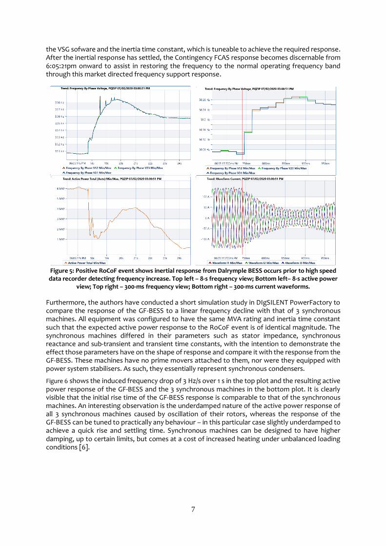
7
the VSG sofware and the inertia time constant, which is tuneable to achieve the required response. After the inertial response has settled, the Contingency FCAS response becomes discernable from 6:05:21pm onward to assist in restoring the frequency to the normal operating frequency band through this market directed frequency support response.
Figure 5: Positive RoCoF event shows inertial response from Dalrymple BESS occurs prior to high speed data recorder detecting frequency increase. Top left – 8-s frequency view; Bottom left– 8-s active power
view; Top right – 300-ms frequency view; Bottom right – 300-ms current waveforms.
Furthermore, the authors have conducted a short simulation study in DIgSILENT PowerFactory to compare the response of the GF-BESS to a linear frequency decline with that of 3 synchronous machines. All equipment was configured to have the same MVA rating and inertia time constant such that the expected active power response to the RoCoF event is of identical magnitude. The synchronous machines differed in their parameters such as stator impedance, synchronous reactance and sub-transient and transient time constants, with the intention to demonstrate the effect those parameters have on the shape of response and compare it with the response from the GF-BESS. These machines have no prime movers attached to them, nor were they equipped with power system stabilisers. As such, they essentially represent synchronous condensers.
Figure 6 shows the induced frequency drop of 3 Hz/s over 1 s in the top plot and the resulting active power response of the GF-BESS and the 3 synchronous machines in the bottom plot. It is clearly visible that the initial rise time of the GF-BESS response is comparable to that of the synchronous machines. An interesting observation is the underdamped nature of the active power response of all 3 synchronous machines caused by oscillation of their rotors, whereas the response of the GF-BESS can be tuned to practically any behaviour – in this particular case slightly underdamped to achieve a quick rise and settling time. Synchronous machines can be designed to have higher damping, up to certain limits, but comes at a cost of increased heating under unbalanced loading conditions [6].

8
Figure 6: Comparison of response to a RoCoF event from a Grid Forming BESS and synchronous machines
in a simulation
The inertial response described in this section demonstrates that a GF-BESS can respond in the same way as a synchronous machine. This property, together with injection of fault currents in excess of the continuous converter rating (discussed in Section 4.2) makes such GF-BESS systems a viable alternative to synchronous generators as contributors to power system security, allowing further fossil-fuelled power plants to switch offline and unlock higher instantaneous penetration of renewable generation sources.
4.2. Fault Current Injection
Most renewable energy plants connecting to the grid are interfaced by means of current-controlled converters. This ever-growing capacity addition is required to decarbonise the electricity and other sectors but brings about challenges to secure power system operation due to displacement of synchronous generation sources. The latter have been the conventional source of fault current injection in the past. Fault current is a factor associated with system strength – a sufficient amount is required to be present in the system at all times to guarantee a safe operation of overcurrent protection devices. Also, injection of fault current from sources at various locations in the power system, in conjunction with the impedances of the system elements, defines the voltage profile across the network during faults.
Both large-scale and distributed renewable energy generation sources coupled via current-controlled converters typically rely on a mechanism such as a phased-locked loop (PLL) to stay synchronised to the fundamental component of the voltage waveform. During faults the suppressed voltage magnitude and potentially distorted waveform may lead to those converters falling out of step and having difficulty to “catch up” post fault clearance. This can lead to a “hunting” behaviour manifesting itself in active/reactive power oscillations and/or reduced power/current output. Grid Forming voltage source converters, in contrary, do not rely on PLLs as they are capable of generating their own voltage waveform, including during times when they ride through faults. This property enables Grid Forming converters to be recognised as contributors to fault current, especially if they can temporarily provide current in excess of their continuous rating. [4]. This is the case for converters installed at the Dalrymple BESS (up to 2 pu for 2 seconds, configurable to lower magnitude if required). Fault current provided by this GF-BESS is used for clearing faults in both the underlying distribution grid as well as within the Wattle Point Wind Farm. Additionally, the overload capability is a useful feature to better cope with the inrush currents

9
accompanying energisation of transformers at or near nominal voltage and to manage transients when running an islanded system.
Large-scale renewable energy plants are often connected at weak grid locations, typically denominated by low short-circuit ratio (SCR), which is typically the case close to the end of long radial lines. Co-location of a GF-BESS with overload capability and a renewable energy plant can improve the plant’s behaviour during faults and reduce its adverse fault-ride-through behaviour related to the issues discussed above. This is achieved by boosting the voltage through fault current injection out of the GF-BESS, which effectively raises the SCR and can help the renewable energy plants equipped with current-controlled converters remain synchronised and online during faults, and prevent the undesired ‘hunting’ associated with active/reactive power oscillations during post fault recovery. This enhances the resilience of the power system and allows more renewable generation capacity to be sited in remote locations, characterised by weak grid (low SCR) interconnection where resources are often most favourable.
4.3. Seamless Islanding
As discussed in Section 3, one of the key regulated services provided by the Dalrymple BESS is reduction of the amount of unserved energy in the area, which effectively means prevention of an outage upon disconnection of the Dalrymple substation from the upstream bulk power system during a fault or contingency event. The system can be islanded on command (planned islanding) or become islanded unexpectedly (unplanned islanding). The latter is more onerous than the former as pre-emptive steps cannot be taken to prepare for a smoother transition, such as reducing the active and reactive power flow across the point of connection to zero and reducing the output of the wind farm to an appropriate level.
A challenge encountered during the control and protection system design is presented by the relative rating of the wind farm (91 MW) to that of the GF-BESS (30 MW). If the wind farm were producing at its full capacity at the instant of unplanned islanding, the GF-BESS may have had to absorb power significantly above its rating until 4 out of 5 wind turbine collectors groups are switched out by the protection relays to reconfigure the wind farm for islanded operation, some 80-100 ms after islanding. Such a large power spike can be demanding for the batteries.
This problem is overcome owing to the synthetic inertia of the GF-BESS, which immediately responds by raising the frequency. This reduces the slip in the induction generators of the wind turbines, instantaneously dropping their power output with the result that the power peak the GF-BESS has to absorb does not exceed 27 MW and therefore remains within the steady-state rating of the batteries. This behaviour is shown in Figure 7, captured by a high-speed data recorder during the real-life test. The wind farm was unable to ride through the event due to its tight over-frequency protection settings which will be raised by the operator over the coming months.
Figure 7: Islanding instant during high wind farm production of 79 MW prior to islanding. Shown here are
frequency (left) and GF-BESS active power (right)
10
However, the GF-BESS remained online and maintained supply throughout the transition and thereafter. A noteworthy remark is that the PSCAD™ model provided with the GF-BESS was able to accurately replicate this frequency behaviour in the system studies [5].
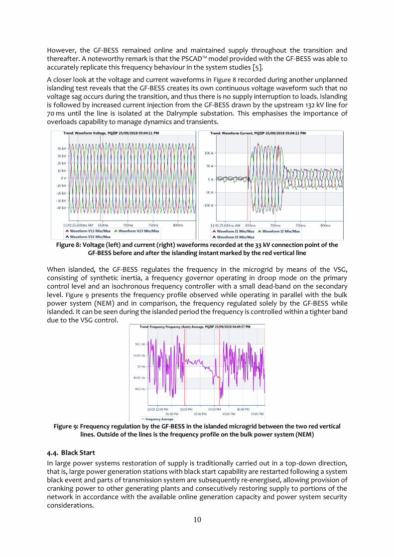
A closer look at the voltage and current waveforms in Figure 8 recorded during another unplanned islanding test reveals that the GF-BESS creates its own continuous voltage waveform such that no voltage sag occurs during the transition, and thus there is no supply interruption to loads. Islanding is followed by increased current injection from the GF-BESS drawn by the upstream 132 kV line for 70 ms until the line is isolated at the Dalrymple substation. This emphasises the importance of overloads capability to manage dynamics and transients.
Figure 8: Voltage (left) and current (right) waveforms recorded at the 33 kV connection point of the
GF-BESS before and after the islanding instant marked by the red vertical line When islanded, the GF-BESS regulates the frequency in the microgrid by means of the VSG, consisting of synthetic inertia, a frequency governor operating in droop mode on the primary control level and an isochronous frequency controller with a small dead-band on the secondary level. Figure 9 presents the frequency profile observed while operating in parallel with the bulk power system (NEM) and in comparison, the frequency regulated solely by the GF-BESS while islanded. It can be seen during the islanded period the frequency is controlled within a tighter band due to the VSG control.
Figure 9: Frequency regulation by the GF-BESS in the islanded microgrid between the two red vertical
lines. Outside of the lines is the frequency profile on the bulk power system (NEM)
4.4. Black Start
In large power systems restoration of supply is traditionally carried out in a top-down direction, that is, large power generation stations with black start capability are restarted following a system black event and parts of transmission system are subsequently re-energised, allowing provision of cranking power to other generating plants and consecutively restoring supply to portions of the network in accordance with the available online generation capacity and power system security considerations.

11
With the advance of Grid Forming utility-scale energy storage such as the Dalrymple BESS, a new potential source for system restoration is now located closer to the consumers and distributed energy resources. Connecting at the substation, the GF-BESS is capable of quickly restoring supply to the associated distribution grid reducing outage time to consumers and providing a voltage source for the distributed energy resources, or even large-scale plants, to synchronise to. Through the converters’ capability to linearly ramp up the voltage the inrush currents of the transformers in the initial energisation path are essentially eliminated. This improves the prospect of successful restoration by reducing the probability of generation/GF-BESS tripping due to overcurrent, and additionally can aid in preventing switching and harmonic overvoltage. Other phenomena associated with running unloaded or lightly loaded systems, such as ferroresonance, may require detailed EMT-type simulation studies but can generally be avoided by ensuring that sufficient damping in form of (resistive) load is present in the distribution grid being energised.
During the energisation the frequency and voltage need to be maintained within an acceptable range. Since the VSG behaves similarly to a synchronous generator through inclusion of synthetic inertia, governor, AVR and rotor flux model, the dynamics of the system behaviour will be dictated by the selected parameters of those control components. Depending on the parameter values, selection of which may be dictated by other requirements such as the inertial response in grid-parallel operation, the frequency and voltage variations during the restoration process may temporarily go outside of the allowed bounds. Some advanced converters have the capability to switch parameters dynamically while operating which allows making the necessary adjustments for specific situations. For instance, the magnitude of the synthetic inertia can be raised for the black start process making the frequency stiffer. Here too care needs to be taken when selecting parameter values since changing parameters of some, in particular faster inner control loops, may lead to undesired interaction between the GF-BESS and power system devices and cause oscillations.
The discussed system restoration approach enabled by the GF-BESS not only reduces outage time through rapid pick-up of the distribution system but can also serve as a source for energisation of upstream transmission lines. This bottom-up approach provides additional flexibility in system operation, albeit adding complexity in managing system restoration out of multiple additional locations. With an appropriate level of automation, operator intervention can be reduced to a reasonable minimum.
At Dalrymple the GF-BESS black starts the local 33 kV distribution network. This is achieved through a soft energization of the GF-BESS coupling transformers (6 x 6 MVA) and one of the substation transformers (25 MVA) with the subsequent energization of the two 33 kV distribution feeders. The transformer energization instant is illustrated in Figure 10 as voltage and current waveforms. While the voltage is ramped up over one second, the currents are so insignificant that they remain below the pick-up threshold of the high-speed recorder. This method eliminates transformer and cable inrush completely.
The active and reactive power profile of the 33 kV feeders during this consecutive load feeder pick-up by the GF-BESS are shown on the right.
Figure 10: Left – Ramp-up of voltage by the GF-BESS to soft energise transformers in the local network;
Middle – Resulting currents are so small that they were not captured by the high-speed recorder; Right – active and reactive power profiles for consecutive energization of two 33 kV distribution load feeders

12
4.5. Fast Active Power Injection
The System Integrity Protection Scheme (SIPS) was devised by ElectraNet following the South Australia system black event in September 2016 to achieve a coordinated fast active power injection from GF-BESS systems in response to the loss of a significant amount of generation within South Australia [9]. The SIPS scheme takes over detection of such a contingency situation and presents the GF-BESS with a binary trigger signal to which it is required to respond with a pre-defined power output (typically maximum available).
The design requirement for the Dalrymple BESS is to provide 30 MW within 250 ms which was successfully demonstrated in the field. Figure 11 illustrates the recorded current waveforms injected by the GF-BESS in response to receipt of the SIPS trigger. For clarity, the difference between the response shown in Figure 8 and the response to the SIPS trigger in Figure 11 is that the latter is a command response (to a setpoint) whereas the former is load current drawn by all loads within the now islanded grid, from the GF-BESS, as it is the only source (the slack bus) within the islanded microgrid, and is effectively instantaneous.
Figure 11: Dalrymple BESS fast active power injection in response to the SIPS trigger; the trigger reception
instant is marked by the red vertical line
5. CONCLUSIONS The Dalrymple 30 MW GF-BESS project has shown how GF-BESS can provide a range of advanced technical services, critical in supporting the operation of high penetration renewable energy power systems. The high power VSG platform and advanced automation deployed as part of the Dalrymple BESS project has enabled the largest autonomous regional microgrid developed to date, operate grid-connected and islanded, with seamless transition between these two states. This unlocked a first-of-its-kind commercial model, the provision of regulated reliability and security services by a Network Service Provider, in addition to competitive market services for an energy generator and retailer. When NEM connected, with the presence of high wind generation in the state of South Australia, the Dalrymple BESS has provided a range of power system stability and support services as outlined in this paper.
Further development of high power, Grid Forming Converter and VSG technology, building on the features demonstrated by the Dalrymple BESS, will provide important reinforcement to future power systems. This can replace services traditionally provided by synchronous generation and unlock higher levels of renewable integration. Specifically, further studies should be carried out to compare and contrast GF-BESS performance against synchronous generators/condensers in the context of enabling individual renewable energy plants to interconnect to weak sections of the grid, as well as supporting large interconnected power systems, such as the NEM, reach renewable energy targets. Further development of Grid Forming Converter technology is also recommended, to enhance and build on some of the key features demonstrated by the Dalrymple BESS, to enable future 100% asynchronous renewable generation bulk power systems to operate reliably and effectievly.

13
BIBLIOGRAPHY [1] Online website of the Dalrymple BESS, www.escri-sa.com.au, last accessed January 2020 [2] Department of the Environment and Energy, Australian Energy Statistics, Table O,
September 2019 [3] Australian Energy Market Operator, “South Australian Renewable Energy Report”, p.3,
November 2017 [4] Aurecon, “Large-Scale Battery Storage Knowledge Sharing Report”, Australian Renewable
Energy Agency, November 2019 https://arena.gov.au/assets/2019/11/large-scale-battery-storage-knowledge-sharing-report.pdf Last accessed Janurary 2020.
[5] ElectraNet report, “ESCRI-SA Battery Energy Storage Project Operational Report #1. First six months (14/12/2018 – 14/06/2019). July 2019
[6] D. Reimert “Protective Relaying for Power Generation Systems”, p. 166f, Taylor & Francis Group, 2006
[7] ElectraNet report, “ESCRI-SA PROJECT SUMMARY REPORT, The Journey to Financial Close” May 2018. Available online at https://www.escri-sa.com.au/globalassets/reports/escri---sa---project-summary-report---the-journey-to-financial-close---may-2018.pdf. Last accessed August 2019.
[8] Tuckey, A., Round, S., “Practical application of a complete virtual synchronous generator control method for microgrid and grid-edge applications”, 2018 IEEE 19th Workshop on Control and Modeling for Power Electronics
[9] ElectraNet report, “SA ENERGY TRANSFORMATION RIT-T. Special Protection Scheme”, 22 May 2019
[10] E. Unamuno, J. Paniagua, J.A. Barrena “Unified Virtual Inertia for ac and dc Microgrids. And the role of interlinking converters.”, IEEE Electrification Magazine, December 2019