parametric cfd analysis of an embaffle heat exchanger · embaffle characteristics: full tube...
TRANSCRIPT

Parametric CFD analysis of an EMbaffle Heat Exchanger
EMbaffle B.V. The Netherlands

Brembana&Rolle Group

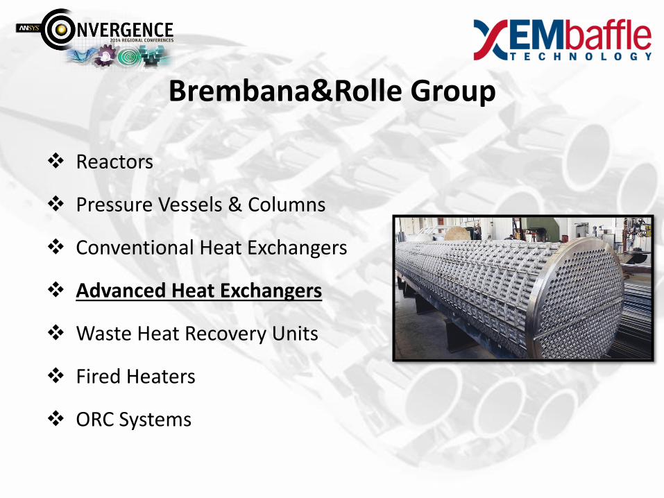
Brembana&Rolle Group
Reactors
Pressure Vessels & Columns
Conventional Heat Exchangers
Advanced Heat Exchangers
Waste Heat Recovery Units
Fired Heaters
ORC Systems

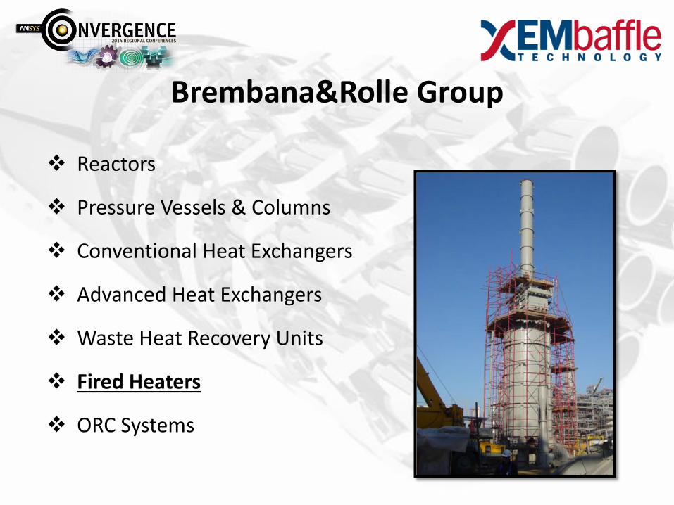
Brembana&Rolle Group
Reactors
Pressure Vessels & Columns
Conventional Heat Exchangers
Advanced Heat Exchangers
Waste Heat Recovery Units
Fired Heaters
ORC Systems

Brembana&Rolle Group
Reactors
Pressure Vessels & Columns
Conventional Heat Exchangers
Advanced Heat Exchangers
Waste Heat Recovery Units
Fired Heaters
ORC Systems
Brembana&Rolle Group
Reactors
Pressure Vessels & Columns
Conventional Heat Exchangers
Advanced Heat Exchangers
Waste Heat Recovery Units
Fired Heaters
ORC Systems

Brembana&Rolle Group
Reactors
Pressure Vessels & Columns
Conventional Heat Exchangers
Advanced Heat Exchangers
Waste Heat Recovery Units
Fired Heaters
ORC Systems
Brembana&Rolle Group
Reactors
Pressure Vessels & Columns
Conventional Heat Exchangers
Advanced Heat Exchangers
Waste Heat Recovery Units
Fired Heaters
ORC Systems

Brembana&Rolle Group
Reactors
Pressure Vessels & Columns
Conventional Heat Exchangers
Advanced Heat Exchangers
Waste Heat Recovery Units
Fired Heaters
ORC Systems
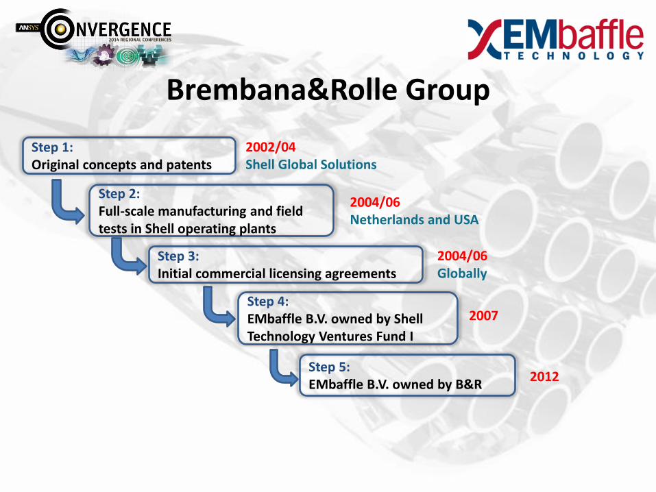
Brembana&Rolle Group
Step 1: Original concepts and patents
Step 2: Full-scale manufacturing and field tests in Shell operating plants
Step 3: Initial commercial licensing agreements
2002/04 Shell Global Solutions
2004/06 Netherlands and USA
2004/06 Globally
2007 Step 4: EMbaffle B.V. owned by Shell Technology Ventures Fund I
2012
Step 5: EMbaffle B.V. owned by B&R

EMbaffle Technology
Grid Production Process:
A sheet of metal is passed through a cutter
It is simultaneously cut and expanded
The resulting expanded sheet is welded to a support ring

EMbaffle Characteristics:
EMbaffle Technology
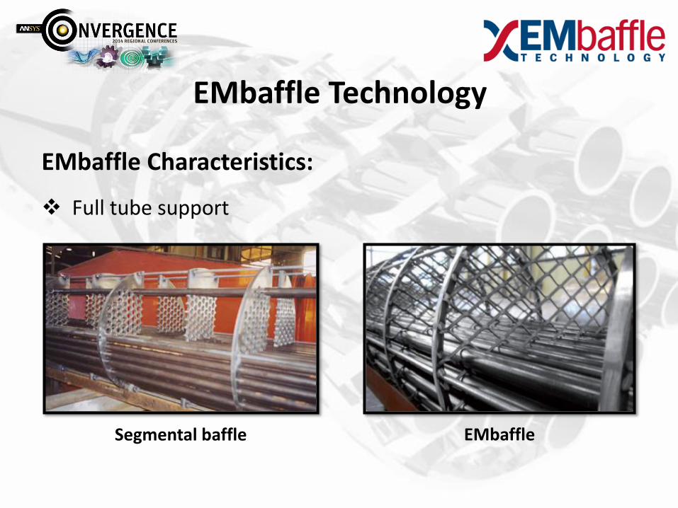
EMbaffle Characteristics:
Full tube support
Segmental baffle EMbaffle
EMbaffle Technology

EMbaffle Characteristics:
Full tube support
Open structure allowing pure longitudinal flow
EMbaffle Segmental baffle
EMbaffle Technology

EMbaffle Characteristics:
Full tube support
Open structure allowing pure longitudinal flow
No tubes vibration
EMbaffle Technology

EMbaffle Characteristics:
Full tube support
Open structure allowing pure longitudinal flow
Enhanced turbulence hence heat transfer coefficient
EMbaffle Technology

EMbaffle Characteristics:
Full tube support
Open structure allowing pure longitudinal flow
Enhanced turbulence hence heat transfer coefficient
More compact design
EMbaffle Technology

EMbaffle Characteristics:
Geometry
(EMbaffle)
Fluid Dynamics
(Turbulence)
Thermodynamics
(Heat Transfer)
Low Shell side Fouling
No Tube Vibration
Low Pressure Drop
Energy & CO2 Savings
EMbaffle Technology

EMbaffle Applications:
Gas-to-gas (Gas Fields, LNG, etc)
Gas-to-liquid (Gas Coolers)
On-shore and off-shore processing
Refining and petrochemical
Concentrated Solar Power (CSP)
Geothermal
EMbaffle Technology
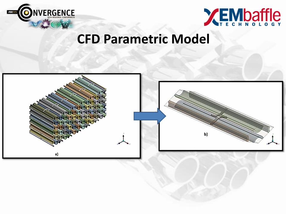
CFD Parametric Model
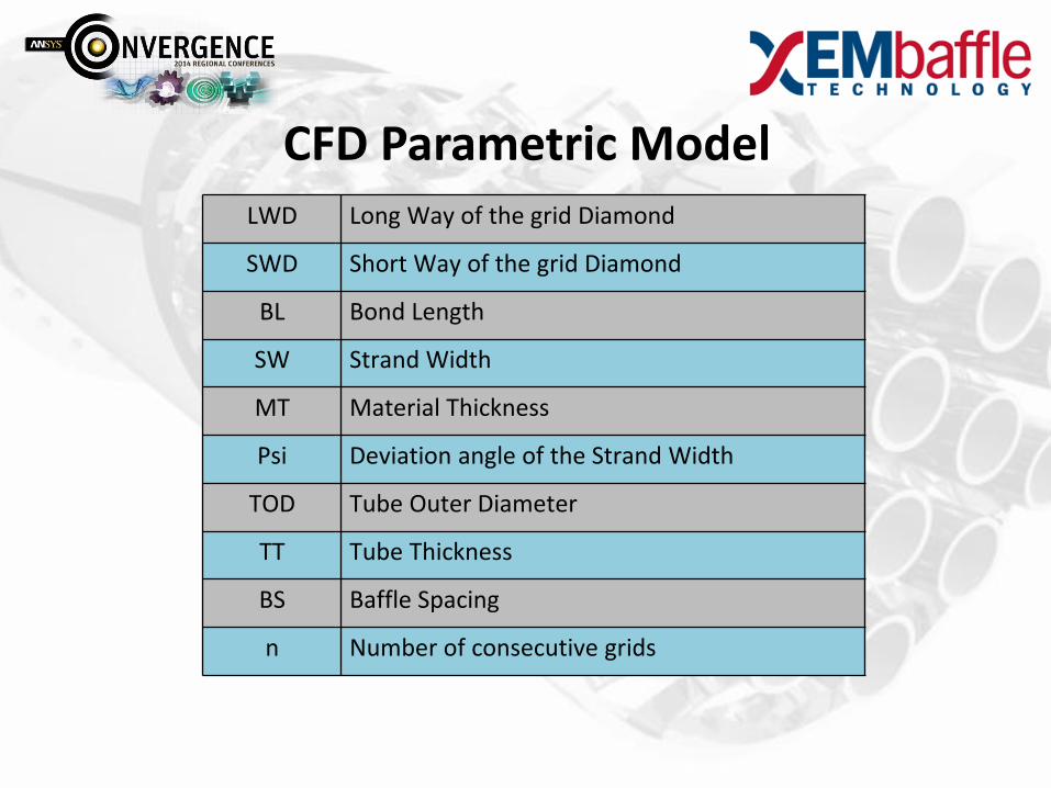
LWD Long Way of the grid Diamond
SWD Short Way of the grid Diamond
BL Bond Length
SW Strand Width
MT Material Thickness
Psi Deviation angle of the Strand Width
TOD Tube Outer Diameter
TT Tube Thickness
BS Baffle Spacing
n Number of consecutive grids
CFD Parametric Model

CFD Parametric Model

a) TubeFluid domain
b) Tube domain
c) ShellFluid domain
CFD Parametric Model

CFD Parametric Model

ShellFluid:
Symmetry
TubeFluid:
translational periodicity
CFD Parametric Model

Starting from 2002, several experimental tests were performed by EMbaffle in collaboration with:
Tests results were used to develop the correlations used to design an EMbaffle heat exchanger by means of the software:
Analysis Cases

Flow direction
Shell-side (n-pentane) Tube-side (water)
Tin (C) vin (m/s) Pin (kPa) Tin (C) vin (m/s) Pin (kPa)
Counter-
current
48 0.223
1636.2 95.64 0.431 665.96
Analysis Cases

Analysis Cases

1) Influence of the turbulence model on the performance
Analysis Cases

1) Influence of the turbulence model on the performance
2) Influence of the baffle spacing on the performance
Analysis Cases

Influence of the turbulence model on the performance:
ShellFluid domain: Shear Stress Transport
Analysis A:
TubeFluid domain: Shear Stress Transport
ShellFluid domain: Detached Eddy Simulation
Analysis B:
TubeFluid domain: Shear Stress Transport
Analysis Case 1

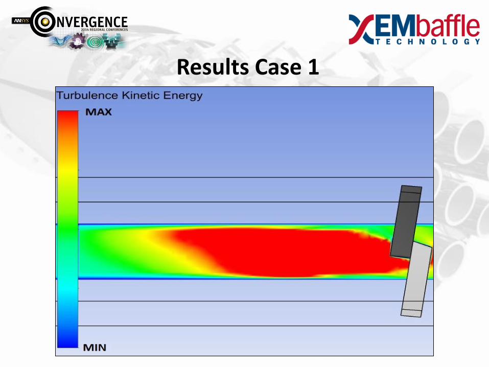
Results Case 1
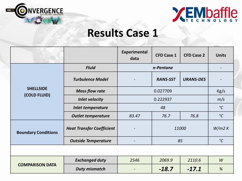
Results Case 1
Results Case 1
Experimental
data CFD Case 1 CFD Case 2 Units
SHELLSIDE
(COLD FLUID)
Fluid n-Pentane -
Turbulence Model - RANS-SST URANS-DES -
Mass flow rate 0.027709 Kg/s
Inlet velocity 0.222937 m/s
Inlet temperature 48 °C
Outlet temperature 83.47 76.7 76.8 °C
Boundary Conditions Heat Transfer Coefficient - 11000 W/m2 K
Outside Temperature - 85 °C
COMPARISON DATA Exchanged duty 2546 2069.9 2110.6 W
Duty mismatch - -18.7 -17.1 %

Influence of the baffle spacing on the performance:
Analysis A: baffle spacing = 50 mm
Analysis B: baffle spacing = 100 mm
Analysis C: baffle spacing = 200 mm
Analysis Case 2

Results Case 2
0.0002
0.0003
0.0004
0.0005
0.0006
0.0007
0.0008
0.0009
0.001
0.0011
0.0012
200 250 300 350 400
T.K
.E [
m^2
/s^2
]
X direction [mm]
BS = 50 mm
BS = 100 mm
BS = 200 mm
FLOW DIRECTION

Results Case 2
Baffle spacing [mm] Turbulence decay distance
from baffle [%]
50 86
100 37
200 18.5

A comparison between some experimental tests and the parametric CFD model was performed in order to validate it.
Two different turbulence models were applied to the shell-side fluid domain to find out which one was better matching the experimental data.
Results show that the CFD model is too conservative in comparison to the real performance of the EMbaffle HEX, even if the DES model seems to better match the real performance.
Conclusion

Performing extensive tests with several fluids (gas, molten salts, etc..) at different Reynolds ranges
Investigating the effect of different grid shapes on the thermal and hydraulic performance
Investigating the optimum baffle spacing in terms of minimum pressure drop and maximum heat transfer coefficient for each application
Simulating two phases flow
Future developments

Thank you for your attention
For further information:
www.EMbaffle.com