parameter tester - fluke corporationassets.fluke.com/manuals/dpm4____umeng0100.pdf ·...
TRANSCRIPT

DPM4 Parameter Tester
Users Manual
PN 2631824 April 2006, Rev. 1, 12/07 © 2006, 2007 Fluke Corporation, All rights reserved. Specifications subject to change without notice. Printed in USA All product names are trademarks of their respective companies.

Warranty and Product Support
Fluke Biomedical warrants this instrument against defects in materials and workmanship for one full year from the date of original purchase. During the warranty period, we will repair or, at our option, replace at no charge a product that proves to be defective, provided you return the product, shipping prepaid, to Fluke Biomedical. This warranty does not apply if the product has been damaged by accident or misuse or as the result of service or modification by other than Fluke Biomedical. IN NO EVENT SHALL FLUKE BIOMEDICAL BE LIABLE FOR CONSEQUENTIAL DAMAGES.
Only serialized products and their accessory items (those products and items bearing a distinct serial number tag) are cov-ered under this one–year warranty. PHYSICAL DAMAGE CAUSED BY MISUSE OR PHYSICAL ABUSE IS NOT COVERED UNDER THE WARRANTY. Items such as cables and nonserialized modules are not covered under this warranty.
Recalibration of instruments is not covered under the warranty.
This warranty gives you specific legal rights, and you may also have other rights which vary from state to state, province to province, or country to country. This warranty is limited to repairing the instrument to Fluke Biomedical’s specifications.
Warranty Disclaimer
Should you elect to have your instrument serviced and/or calibrated by someone other than Fluke Biomedical, please be advised that the original warranty covering your product becomes void when the tamper-resistant Quality Seal is removed or broken without proper factory authorization. We strongly recommend, therefore, that you send your instrument to Fluke Bio-medical for factory service and calibration, especially during the original warranty period.

Notices
All Rights Reserved © Copyright 2007, Fluke Biomedical. No part of this publication may be reproduced, transmitted, transcribed, stored in a retrieval system, or translated into any language without the written permission of Fluke Biomedical.
Copyright Release Fluke Biomedical agrees to a limited copyright release that allows you to reproduce manuals and other printed materials for use in service training programs and other technical publications. If you would like other reproductions or distributions, submit a written request to Fluke Biomedical.
Unpacking and Inspection Follow standard receiving practices upon receipt of the instrument. Check the shipping carton for damage. If damage is found, stop unpacking the instrument. Notify the carrier and ask for an agent to be present while the instrument is unpacked. There are no special unpacking instructions, but be careful not to dam-age the instrument when unpacking it. Inspect the instrument for physical damage such as bent or broken parts, dents, or scratches.
Technical Support For application support or answers to technical questions, either email [email protected] or call 1-800- 648-7952 or 1-425-446-6945.
Claims Our routine method of shipment is via common carrier, FOB origin. Upon delivery, if physical damage is found, retain all packing materials in their original condition and contact the carrier immediately to file a claim. If the instrument is delivered in good physical condition but does not operate within specifica-tions, or if there are any other problems not caused by shipping damage, please contact Fluke Biomedical or your local sales representative.

Standard Terms and Conditions Refunds and Credits
Please note that only serialized products and their accessory items (i.e., products and items bearing a distinct serial number tag) are eligible for partial refund and/or credit. Nonserialized parts and accessory items (e.g., cables, carrying cases, auxiliary modules, etc.) are not eligible for re-turn or refund. Only products returned within 90 days from the date of original purchase are eligible for refund/credit. In order to receive a partial re-fund/credit of a product purchase price on a serialized product, the product must not have been damaged by the customer or by the carrier chosen by the cus-tomer to return the goods, and the product must be returned complete (meaning with all manuals, cables, accessories, etc.) and in “as new” and resalable con-dition. Products not returned within 90 days of purchase, or products which are not in “as new” and resalable condition, are not eligible for credit return and will be returned to the customer. The Return Procedure (see below) must be followed to assure prompt refund/credit.
Restocking Charges Products returned within 30 days of original purchase are subject to a minimum restocking fee of 15 %. Products returned in excess of 30 days af-ter purchase, but prior to 90 days, are subject to a minimum restocking fee of 20 %. Additional charges for damage and/or missing parts and accesso-ries will be applied to all returns.
Return Procedure All items being returned (including all warranty-claim shipments) must be sent freight-prepaid to our factory location. When you return an instrument to Fluke Biomedical, we recommend using United Parcel Service, Federal Express, or Air Parcel Post. We also recommend that you insure your shipment for its actual replacement cost. Fluke Biomedical will not be responsible for lost shipments or instruments that are received in damaged condition due to improper packaging or handling. Use the original carton and packaging material for shipment. If they are not available, we recommend the following guide for repackaging:
Use a double–walled carton of sufficient strength for the weight being shipped. Use heavy paper or cardboard to protect all instrument surfaces. Use nonabrasive material around all projecting parts. Use at least four inches of tightly packed, industry-approved, shock-absorbent material around the instrument.

Returns for partial refund/credit: Every product returned for refund/credit must be accompanied by a Return Material Authorization (RMA) number, obtained from our Order Entry Group at 1-800-648-7952 or 1-425-446-6945. Repair and calibration: To find the nearest service center, goto www.flukebiomedical.com/service or In the U.S.A.: Cleveland Calibration Lab Tel: 1-800-850-4606 Email: [email protected] Everett Calibration Lab Tel: 1-800-850-4606 Email: [email protected] In Europe, Middle East, and Africa: Eindhoven Calibration Lab Tel: +31-402-675300 Email: [email protected] In Asia: Everett Calibration Lab Tel: +425-446-6945 Email: [email protected]
Certification This instrument was thoroughly tested and inspected. It was found to meet Fluke Biomedical’s manufacturing specifications when it was shipped from the factory. Calibration measurements are traceable to the National Institute of Standards and Technology (NIST). Devices for which there are no NIST calibra-tion standards are measured against in-house performance standards using accepted test procedures.
WARNING Unauthorized user modifications or application beyond the published specifications may result in electrical shock hazards or improper operation. Fluke Bio-medical will not be responsible for any injuries sustained due to unauthorized equipment modifications.

Restrictions and Liabilities Information in this document is subject to change and does not represent a commitment by Fluke Biomedical. Changes made to the information in this document will be incorporated in new editions of the publication. No responsibility is assumed by Fluke Biomedical for the use or reliability of software or equipment that is not supplied by Fluke Biomedical, or by its affiliated dealers.
Manufacturing Location The DPM4 Parameter Tester is manufactured by Fluke Biomedical, Everett WA.

i
Table of Contents
Title Page Introduction .................................................................................................................... 1 Safety ............................................................................................................................. 1 Specifications ................................................................................................................. 3
General...................................................................................................................... 3 Pressure Measurement ............................................................................................. 4 Temperature Measurement ....................................................................................... 5 Barometric Pressure.................................................................................................. 5 Gas Flow ................................................................................................................... 6 Relative Humidity....................................................................................................... 6
Controls and Connections .............................................................................................. 6 Powering the Tester ....................................................................................................... 10 Operating the Tester ...................................................................................................... 10 Running Tests ................................................................................................................ 11
Pressure / Temperature............................................................................................. 11 Gas Flow / Temperature (Models 2G and 2H)........................................................... 11 Barometric Pressure and Relative Humidity (Models 2G and 2H) ............................. 16
Cleaning the Tester ........................................................................................................ 16

ii
List of Tables
Table Title Page
1. Controls and Connections..................................................................................................... 8 2. Pressure and Temperature Tests ......................................................................................... 13 3. Gas Flow and Temperature Tests......................................................................................... 15
List of Figures
Figure Title Page
1. Controls and Connections..................................................................................................... 7 2. Pressure and Temperature Tests ......................................................................................... 12 3. Gas Flow and Temperature Tests......................................................................................... 14 4. Barometric Pressure and Relative Humidity.......................................................................... 16

1
DPM4 Parameter Tester
Introduction The DPM4 Parameter Tester (hereafter called the Tester) is a compact, lightweight, high-performance parameter tester for use by trained service technicians for calibrating or testing medical and industrial devices.
It is a versatile test instrument, able to measure multiple parameters. Basic parameters cover pressure, vacuum, and temperature measurements (Models 1H and 1G).
Gas flow, barometric pressure and humidity measurements are included in the enhanced Tester (Models 2H and 2G). The Tester is menu-driven and simple to operate. All functions are set from a 128 x 32 pixel graphical display.
Safety
WXWarning. Read before using the Tester. To avoid personal injury, follow these guidelines:
Do not use the Tester in any manner not specified in the Users Manual. Otherwise, the protection provided by this product may be impaired.
• Always press power off on the Tester and unplug the Battery Eliminator before cleaning the outer surface.

DPM4 Users Manual
2
• Inspect the product. If the Tester appears damaged or appears to operate in a manner not specified in the manual, DO NOT CONTINUE USE. Return the product for service.
• Avoid spilling liquids on the Tester; fluid seepage into internal components creates corrosion and a potential shock hazard. Do not operate the instrument if there is internal component exposure to fluid.
• Do not open this product. There are no user replaceable parts.
WCaution
Calibrate the Tester annually. Only qualified technical personnel should perform troubleshooting and service procedures on the Tester.
Do not expose the Tester to temperature extremes. Ambient operating temperatures should remain between 15 and 35 °C. Tester performance may degrade if temperatures fluctuate above or below this range.
Clean only with a damp, lint-free cloth, using a mild detergent, and wipe down gently.
Symbol Description
W See Users Manual.
X Caution risk of electric shock
P Manufacturer’s declaration of product compliance with applicable EU directives
… Battery Eliminator Port
~ Do not dispose of this product as unsorted municipal waste. Go to Fluke’s website for recycling information.

Parameter Tester Specifications
3
Specifications
General
Display....................................................................LCD graphic display, 128 x 32 pixels Data Input/Outputs (1)...........................................Bi-directional RS-232C for computer control Case ........................................................................ABS plastic case Weight ....................................................................0.4 kg / 0.9 lbs. with battery Dimensions ............................................................D x W x H: 34 mm x 94 mm x 156 mm (1.3 in x 3.7 in x 6.1 in) Environmental .......................................................Indoor use
Temperature, Operating........................................15 °C to 35 °C (59 °F to 95 °F)
Temperature, Storage ...........................................0 °C to 50 °C (32 °F to 122 °F)
Maximum Humidity, Operating ...........................80 % relative humidity up to 31 °C (88 °F), decreasing linearly to 50 % relative humidity at 40 °C (104 °F).
Maximum Humidity, Storage ...............................95 % Altitude ...................................................................Up to 2000 m
Battery Power Supply Voltage ...............................................................9 VDC Power Consumption ...........................................< 70 mA Battery Life .........................................................> 7 hours
External Power Supply Output Voltage ...................................................12 to 15 V Output Current ....................................................1.2 A

DPM4 Users Manual
4
Models DPM4-1G ............................................................2631330 DPM4-1H ............................................................2583121 DPM4-2G ............................................................2637772 DPM4-2H ............................................................2637760
Standard Accessories Users Manual CD-ROM ......................................2637785 Users Manual (printed)........................................2631824 Tubing Kit ............................................................2461931 9 VDC Battery Eliminator ....................................2647372
Optional Accessories PT-100 Temperature Probe ................................2461910 PT-1000 Temperature Probe ..............................2461922 Expansion Chamber............................................2461905 Inflation Bulb .......................................................2461946
Pressure Measurement DPM4 Model 1H or 2H
Operating range .................................................. -350 to +350 mmHg Accuracy .............................................................± 0.3 % of range Resolution ...........................................................0.1 mmHg Units of measure .................................................mmHg, mBar, cmH2O, PSI, InHg, InH2O, kgcm2, and kPa
DPM4 Model 1G or 2G Operating range .................................................. -700 to +5000 mmHg Accuracy .............................................................0.3 % of range for temperatures from 21 to 25 °C and relative humidity from 30 to 70 %;
0.3 % of range plus 0.02 % of range per degree C for temperatures <21 °C or >25 °C with relative humidity from 30 to 70 %

Parameter Tester Specifications
5
Resolution ...........................................................0.5 mmHg Units of measure .................................................mmHg, mBar, cmH2O, PSI, InHg, InH2O, kgcm2, and kPa
Temperature Measurement Operating range.....................................................-40 °C to +200 °C Accuracy ................................................................±(2 % of reading, +0.5 °C) Resolution ..............................................................0.1 °C and °F Units of measure ...................................................°C and °F Use standard external temperature probe type PT-100 or PT-1000 (DIN/IEC 751 Class A) for temperature measurements in °C or °F. PT-100 Temperature Probe
Operating range ..................................................-50 °C to +200 °C Accuracy..............................................................0.13 °C @ -100 °C, 0.1 °C @ 0 °C, 0.2 °C @ 100 °C
PT-1000 Temperature Probe Operating range ..................................................-50 °C to +200 °C Accuracy..............................................................0.3 °C
Barometric Pressure DPM4 Model 2G or 2H It is possible to compensate for sea level and calibrate for offsets.
Operating range ..................................................380 to 900 mmHg Accuracy..............................................................2 % of reading ±1 LSD Resolution ...........................................................1 mmHg Units of measure .................................................mmHg, mBar, inHg, and hPa

DPM4 Users Manual
6
Gas Flow DPM4 Model 2G or 2H These models measure with an embedded sensor with 11 calibration points to compensate for nonlinearity. The Tester stores calibration constants in firmware.
Operating range .................................................. -750 to +750 ml/min Accuracy .............................................................1 % of range or 5 % of reading, whichever is greater Resolution ...........................................................0.1 ml/min Compatibility........................................................Air, N2, O2, CO2, H2, and He Units of measure .................................................ml/min (or SCCM - Standard Cubic Centimeters per Minute)
Relative Humidity DPM4 Model 2G or 2H An integrated sensor in the Tester determines relative humidity measurements.
Operating range ..................................................12 to 95 % RH Accuracy .............................................................3.5 % of reading ±2 % RH @ 25 °C for RH between 12 % and 95 % RH Resolution ...........................................................1 % RH Gas compatibility.................................................Air Units of measure .................................................% RH
Controls and Connections This section describes the controls and connections of the Tester. Refer to Figure 1 and Table 1.

Parameter Tester Controls and Connections
7
OPEN
PRESS/TEMP
FLOW/TEMP
ENVIRONMENT
MENU SCROLL
DPM4
F1 F2 F3 F4
PARAMETER TESTER
10
6
7
8
9
1
2
3
4
5
Front Panel Back Panel
Left Side Panel
Top Panel
eig01f.eps
Figure 1. Controls and Connections

DPM4 Users Manual
8
Table 1. Controls and Connections
Number Name Description
A LCD Display 1.8 cm x 5.8 cm (.7 in. x 2.3 in.) 128 x 32 pixel window displaying messages, test results, and function menus.
B Function Keys Used to select various preset test parameter options and run the tests.
C MENU SCROLL Keys
Used to navigate between and confirm the various preset test parameter options.
Test Keys Pressing one of these keys opens the relevant test screen:
PRESS / TEMP Pressure / Temperature Test.
With DPM4 Models 2G and 2H, you can perform the following additional tests:
FLOW / TEMP Gas Flow / Temperature Test.
D
ENVIRONMENT Barometric Pressure / Relative Humidity Test.
E On / Off Switches the Tester on and off.
F Battery Compartment
Compartment for holding a 9-V alkaline battery.

Parameter Tester Controls and Connections
9
Table 1. Controls and Connections (cont.)
Number Name Description
G Temp. 8-pin mini-DIN plug connector for the temperature cable. Use standard external temperature probe type PT-100 or PT-1000 (DIN/IEC 751 Class A) for temperature measurements in °C or °F.
H RS-232 8-pin mini-DIN plug for connecting an RS-232 cable. Use this connection for uploading new firmware, transferring measuring results, and calibration. You need a customized cable to use this interface.
I Battery Eliminator For use in operating the Tester from any standard electrical outlet. To ensure safe operation, use only the Fluke Biomedical Battery Eliminator (PN 2647372).
WXWarning Caution risk of electric shock. Use only the Battery Eliminator specified in this manual or the protection provided may be impaired.
J Pressure Pressure port connector.
DPM4 Users Manual
10
Powering the Tester The Tester uses a 9-volt alkaline battery. It uses as much of the battery as possible. When it detects less than about 6.8 V, it sounds a continuous tone alarm. When it detects less than 6.0 V, it goes into a shutdown mode
The battery resides in the base of the instrument. Use a 9-volt alkaline battery (Duracell® MN1604 or equivalent). Do not use a mercury, air, or carbon-zinc battery.
W Warning The 9-volt alkaline battery provided with the Tester may explode or leak if recharged, inserted improperly, disposed of in a fire, or mixed with different battery types. Dispose of the battery in accordance with any applicable state or local regulations.
As an alternative to a battery, you can power the Tester with a Fluke Biomedical Battery Eliminator. To ensure safe operation, use only a Fluke Biomedical Battery Eliminator (PN 2647372).
WXWarning Caution risk of electric shock. Use only the Battery Eliminator specified in this manual or the protection provided may be impaired.
Note
Remove the battery and disconnect the Battery Eliminator if you do not intend to use the Tester for an extended period.
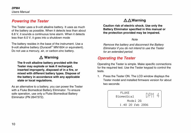
Operating the Tester Operating the Tester is simple. Make specific connections for the required test. Use the Tester keypad to control the tests.
1. Press the Tester ON. The LCD window displays the Tester model and installed firmware version for about two seconds:

Parameter Tester Running Tests
11
2. The window then displays the pressure / temperature display. This is the default test.
Note
The display indicates when there is a temperature sensor attached to the Tester. Otherwise, “NA” appears in the display.
3. Select the F1-F4 function keys to set the test parameter presets. Use MENU SCROLL > to navigate among the various options. Press the F1-F4 function key under the required test preset. Press < MENU SCROLL to confirm the required preset.
4. For Tester Models 2G and 2H, press a test key to go to a test screen other than the default pressure / temperature test. After reaching the required test, select the F1-F4 function keys to set the test parameter presets. Use MENU SCROLL > to
navigate among the various options. Press the F1-F4 function key under the required test preset. Press < MENU SCROLL to confirm the required preset.
Running Tests This section describes Tester test procedures by function. If you are unfamiliar with basic Tester operation, refer to “Operating the Tester.”
Pressure / Temperature
When you select PRESS/TEMP, the selections shown in Figure 2 and described in Table 2 are available.
Gas Flow / Temperature (Models 2G and 2H)
If you select FLOW/TEMP, the selections shown in Figure 3 and described in Table 3 are available. The Tester switches on the gas flow sensor power supply. The battery save function prevents turning power on for this circuit beforehand. The sensor needs approximately one minute to warm up before the measuring result is accurate.

DPM4 Users Manual
12
1 7
4
3
2
5 6
eig16f.eps
Figure 2. Pressure and Temperature Tests

Parameter Tester Running Tests
13
Table 2. Pressure and Temperature Tests
Number Description
A Peak (F1): The Tester displays Peaktest as long as the measurement is continuing. The Tester displays the highest value of the measurement. You can reset the measurement with the F4 key. Leak (F2): By selecting F1-F4, you can set the time for the leak measurement. You can set this interval to 15, 30, 45, or 60 seconds. The Tester displays the time difference between the start and stop pressures. Unit (F3): The Tester can display the result in the following units: mmHg, inHO, mBar, cmHo, kPa, inHg, PSI, Kgcm, and C/F. You can choose sets of selections using MENU SCROLL > or < MENU SCROLL. Zero (F4): Resets the pressure measurement. This function should only be used to set zero and not for relative measurements in proportion to a given pressure.
B Press < MENU SCROLL to return to the preceding screen. Reset (F4) resets the measurement in progress to zero.
C To start the test, pressurize the circuit. Select the required time for the measurement by pressing the appropriate F1-F4 key. The result then appears after this time expires. Press < MENU SCROLL to return to the preceding screen.
D
E
F
Press MENU SCROLL > to view the available units of measurement. Select the required unit by pressing the appropriate F1-F4 key. Press < MENU SCROLL to confirm the selection.
G Resets the pressure measurement.

DPM4 Users Manual
14
1 6
5
2 3
4
eig17f.eps
Figure 3. Gas Flow and Temperature Tests

Parameter Tester Running Tests
15
Table 3. Gas Flow and Temperature Tests
Number Description
A Gas (F1): Sets the type of gas you are using for the measurement.
Note
This parameter must be set correctly to make accurate measurements.
Unit (F2): Sets SCCM, ml/min for gas flow, and °C/F for the temperature. Peak (F3): The Tester displays Peaktest as long as the measurement is continuing. The Tester displays the highest measurement value. Reset the measurement with the F4 key. Zero (F4): Resets the flow measurement. This function should only be used to set zero, and not for relative measurements in proportion to a given pressure.
B
C
Press < MENU SCROLL or MENU SCROLL > to view the available types of gas. Select the required type of gas by pressing the appropriate F1-F4 key. Press < MENU SCROLL to validate the selection.
D Select the unit of gas flow with the F1 or F2 key, and the unit of temperature with the F4 key. Press < MENU SCROLL to confirm the selection(s).
Note
An optional PT-100 or PT-1000 temperature probe is necessary for the temperature measurement.
E Press < MENU SCROLL to return to the preceding screen. Reset resets the measurement in progress to zero
F Zeros the flow measurement.

DPM4 Users Manual
16
Barometric Pressure and Relative Humidity (Models 2G and 2H)
When you have selected ENVIRONMENT, the Tester switches on the power supply for the barometric pressure sensor. The sensor needs about ten seconds to warm up before the measurement results are reliable.
Use the F1 to F4 keys to select the barometric pressure measuring unit. See Figure 4. The Tester then measures the barometric pressure and the relative humidity. Return by pressing a test key.
F1 F2 F3 F4
hPa
N.A. hPa N.A. %RH
mmHg mBar inHg
ebu15s.eps
Figure 4. Barometric Pressure and Relative Humidity
Cleaning the Tester Clean the outside of the Tester using a damp cloth with mild detergent. Please note that some solvents like methanol may damage the overlay and case.
W Caution
Do not pour fluid onto the Tester surface; fluid seepage into the electrical circuitry may cause Tester failure.
W Caution
Do not use spray cleaners on the Tester; such action may force cleaning fluid into the Tester and damage electronic components.