parallel circuit name multiple choice · a)9 w b)6 w c)3 w d)less than 3 w 25.the total resistance...
TRANSCRIPT

Parallel Circuit Name______Multiple Choice
A) The potential difference across the 6-ohmresistor is the same as the potential differenceacross the 3-ohm resistor.
B) The potential difference across the 6-ohmresistor is twice as great as the potentialdifference across the 3-ohm resistor.
C) The potential difference across the 6-ohmresistor is half as great as the potential differenceacross the 3-ohm resistor.
D) The potential difference across the 6-ohmresistor is four times as great as the potentialdifference across the 3-ohm resistor.
1. A 3-ohm resistor and a 6-ohm resistor are connectedin parallel across a 9-volt battery. Which statementbest compares the potential difference across eachresistor?
A) V1 reads 2.0 V and V2 reads 4.0 VB) V1 reads 4.0 V and V2 reads 2.0 VC) V1 reads 3.0 V and V2 reads 3.0 VD) V1 reads 6.0 V and V2 reads 6.0 V
2. In the circuit diagram below, what are the correctreadings of voltmeters V1 and V2?
A) decrease B) increaseC) remain the same
3. In the diagram below, lamps L1 and L2 are connectedto a constant voltage power supply.
If lamp L1 burns out, the brightness of L2 will
A) 6.0 volts B) 2.0 voltsC) 3.0 volts D) 12 volts
4. In the circuit shown at the right, the potentialdifference across the 4.0-ohm resistor is
A) 1.0 V B) 2.0 V C) 3.0 V D) 1.5 V
5. In the circuit diagramabove, what is the potential difference across the3.0-ohm resistor?
A) decreases B) increasesC) remains the same
6. As the number of resistors connected in parallel to aconstant voltage source is increased, the potentialdifference across each resistor
A)
B)
C)
D)
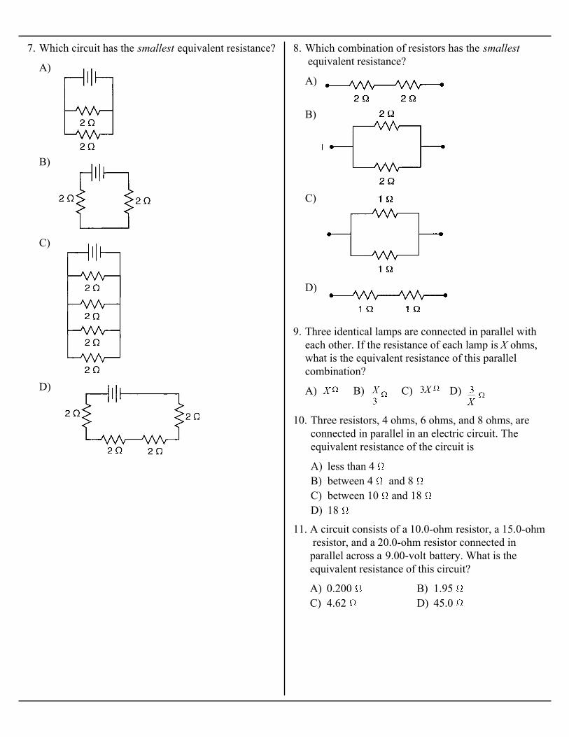
7. Which circuit has the smallest equivalent resistance?
A)
B)
C)
D)
8. Which combination of resistors has the smallest equivalent resistance?
A) B) C) D)
9. Three identical lamps are connected in parallel witheach other. If the resistance of each lamp is X ohms,what is the equivalent resistance of this parallelcombination?
A) less than 4 B) between 4 and 8 C) between 10 and 18 D) 18
10. Three resistors, 4 ohms, 6 ohms, and 8 ohms, areconnected in parallel in an electric circuit. Theequivalent resistance of the circuit is
A) 0.200 B) 1.95 C) 4.62 D) 45.0
11. A circuit consists of a 10.0-ohm resistor, a 15.0-ohm resistor, and a 20.0-ohm resistor connected inparallel across a 9.00-volt battery. What is theequivalent resistance of this circuit?

12. Base your answer to the following question on the diagram below, which represents an electric circuitconsisting of four resistors and a 12-volt battery.
A) 72 B) 18 C) 3.0 D) 0.33
What is the equivalent resistance of this circuit?
A) 1 B) 2 C) 8 D) 4
13. Two identical resistors connected in series have anequivalent resistance of 4 ohms. The same tworesistors, when connected in parallel, have anequivalent resistance of
A) 0.67 B) 1.5 C) 6.3 D) 19
14. The diagram below represents part of an electriccircuit containing three resistors.
What is the equivalent resistance of this part of thecircuit?
15. Base your answer to the following question on thecircuit diagram below.
A) 8.0 B) 2.0 C) 3.0 D) 16
If switch S1 is closed, the equivalent resistance of thecircuit is

A) B)
C) D)
16. In which circuit would ammeter A show the greatest current?
A) 20. B) 40. C) 80. D) 160
17. Two identical resistors connected in parallel have anequivalent resistance of 40. ohms. What is theresistance of each resistor?
18. Base your answer to the following question on thecircuit diagram below, which shows two resistorsconnected to a 24-volt source of potential difference.
A) 0.42 B) 2.4 C) 5.0 D) 10
What is the total resistance of the circuit?
A) 1.0 B) 9.0 C) 3.0 D) 27
19. What is the total resistance of the circuit segmentshown in the diagram below?
A) series circuit with an equivalent resistance of36 ?
B) series circuit with an equivalent resistance of4.0 ?
C) parallel circuit with an equivalent resistance of36 ?
D) parallel circuit with an equivalent resistance of4.0 ?
20. A physics student is given three 12-ohm resistorswith instructions to create the circuit that wouldhave the lowest possible resistance. The correctcircuit would be a
21. Base your answer to the following question on thediagram below, which shows two resistors connectedin parallel across a 6.0-volt source.
A) .75 B) 2.0 C) 1.3 D) 4.0
The equivalent resistance of the two resistors is

A) 15 ohm B) 2.0 ohmC) 10. ohm D) 45 ohm
22. If a 15-ohm resistor is connected in parallel with a30.-ohm resistor, the equivalent resistance is
A) 1 B) 5 C) 8 D) 4
23. Resistors R1 and R2 have an equivalent resistance of6 ohms when connected in the circuit shown below.
The resistance of R1 could be
Base your answers to questions 24 and 25 on thediagram below.
A) 6 V B) 9 V C) 3 V D) 10 V
24. The voltage drop across R 1 is
A) 9 W B) 6 WC) 3 W D) less than 3 W
25. The total resistance in the circuit is
A) less than 5 ohmsB) 5 ohmsC) 15 ohmsD) greater than 15 ohms
26. The diagram below shows a resistor of 5 ohms and aresistor of 10 ohms connected in parallel in a circuit.What is the total resistance of the circuit?
A) decreases B) increasesC) remains the same
27. As more resistors are added in parallel, the totalresistance of a circuit
A)
B)
C)
D)
28. Which diagram represents resistances connected inseries?

A) equal to the sum of the separate resistancesB) equal to the largest resistanceC) smaller than the smallest resistanceD) greater than the largest resistance
29. The total resistance of several resistors connected inparallel is
A) A and B B) B and CC) C and D D) D and A
30. Which two of the resistor arrangements shown belowhave equal resistances?
A) less B) greaterC) the same
31. Circuit A and circuit B are shown below.
Compared to the total resistance of circuit A, thetotal resistance of circuit B is
A)
B)
C)
D)
32. Which circuit segment below has the same totalresistance as the circuit segment shown in thediagram?
A) less than B) between and C) between and D) greater than
33. Three resistances of 2 ohms, 4 ohms, and 6 ohms areconnected in parallel. The equivalent resistance ofthe three resistors is

Base your answers to questions 34 through 36 on thediagram below.
A) 24 V B) 18 V C) 6.0 V D) 4.0 V
34. The potential difference across R2 is
A) decrease B) increaseC) remain the same
35. If a third resistance is added in parallel to the 24-voltsource, the combined resistance of the circuit will
A) B) C) D)
36. The combined resistance of resistors R1 and R2 is
A) 8 W B) 2 W C) 16 W D) 4 W
37. Two identical resistors connected in series have acombined resistance of 8 ohms. When connected inparallel, the resistance of the combination will be
A) 5 A B) 20 AC) 600 A D) 12 000 A
38. What is the total current in a circuit consisting of sixoperating 100-watt lamps connected in parallel to a120-volt source?
A) 1 A B) 2 A C) 3 A D) 4 A
39. The diagram below represents currents in a segmentof an electric circuit.
What is the reading of ammeter A?
A) 1.0 A B) 0.10 AC) 5.5 A D) 11 A
40. In the diagram below of a parallel circuit, ammeter A measures the current supplied by the 110-voltsource.
The current measured by ammeter A is
A) decrease B) increaseC) remain the same
41. In the circuit at the right, if an ammeter is movedfrom position 1 to position 2, the current measuredwill
A) 1.0 A B) 2.0 A C) 3.0 A D) 7.0 A
42. Three ammeters are placed in a circuit as shownbelow.
If Al reads 5.0 amperes and A2 reads 2.0 amperes,what does A3 read?

A) 1.0 A B) 2.0 A C) 3.0 A D) 5.0 A
43. Ammeters A1, A2 and A3 are placed in a circuit asshown below.
What is the reading on ammeter A3?
Base your answers to questions 44 through 46 on the diagram of the circuit below.
A) decrease B) increaseC) remain the same
44. If resistance R2 were removed, the potentialdifference across R1 would
A) decrease B) increaseC) remain the same
45. If resistance R2 were removed, the current inammeter A would
A) 1.0 A B) 2.0 A C) 6.0 A D) 8.0 A
46. The current in ammeter A is
A) 1 A B) 0 A C) 3.5 A D) 7 A
47. The diagram below represents a segment of a circuit.What is the current in ammeter A?
A) 5 A B) 7 A C) 3 A D) 8 A
48. Three ammeters are located near junction P in adirect current circuit as shown in the diagram below.
If ammeter Al reads 3 amperes and ammeter A2 reads4 amperes, then what does ammeter A3 read?

A) B)
C) D)
49. In which circuit would current flow through resistor R 1, but not through resistor R 2 while switch S isopen?
A) 6.0 A B) 10. A C) 20. A D) 4.0 A
50. In the circuit diagram shown below, ammeter A1 reads 10. amperes.
What is the reading of ammeter A2?
Base your answers to questions 51 and 52 on theinformation and diagram below. A 20.-ohm resistorand a 30.-ohm resistor are connected in parallel to a12-volt battery as shown. An ammeter is connectedas shown.
A) 10. B) 12 C) 25 D) 50.
51. What is the equivalent resistance of the circuit?
A) 1.0 A B) 0.60 AC) 0.40 A D) 0.20 A
52. What is the current reading of the ammeter?

A) B)
C) D)
53. Which diagram shows correct current direction in a segment of an electric circuit?
A) B)
C) D)
54. Which diagram below correctly shows currents traveling near junction P in an electric circuit?
A) 9 A toward P B) 9 A toward QC) 5 A toward P D) 5 A toward Q
55. The diagram below shows electric currents inconductors that meet at junction P.
What are the magnitude and direction of the currentin conductor PQ?
A) The lamp has less resistance than the heatingelement.
B) The lamp has more resistance than the heatingelement.
C) The lamp and the heating element wereconnected in series.
D) The lamp and the heating element wereconnected in parallel.
56. An electric circuit contains an operating heatingelement and a lit lamp. Which statement bestexplains why the lamp remains lit when the heatingelement is removed from the circuit?

A) 1 A B) 1/3 A C) 3 A D) 9 A
57. What is the current in ammeter A in the diagrambelow?
Base your answers to questions 58 through 61 on theelectric circuit below. The switch is in the openposition.
A) less B) greaterC) the same
58. Compared to the potential drop across the 10.-ohmresistor, the potential drop across the resistor is
A) less B) greaterC) the same
59. Compared to the current passing through ammeter A1 when the switch is open, the current passingthrough ammeter A1 when the switch is closed willbe
A) 9.0 amperes B) 2.0 amperesC) 12 amperes D) 18 amperes
60. What is the reading of ammeter A2?
A) 1/6 ampere B) 6.0 amperesC) 60. amperes D) 600 amperes
61. What is the reading of ammeter A1?
A) 1 A B) 5 A C) 7 A D) 8 A
62. The diagram below shows the current in a segmentof a direct current circuit.
What is the reading of ammeter A?
A) 8 A B) 2 A C) 3 A D) 13 A
63. The diagram below shows currents in a segment ofan electric circuit.
What is the reading of ammeter A?
A) 1 and 4 B) 2 and 3C) 1, 2, and 3 D) 2, 3, and 4
64. In the circuit represented below, which switchesmust be closed to produce a current in conductor AB?
65. Base your answer to the following question on the information below.
An electric heater rated at 4,800 watts is operated on120 volts.
A) decrease B) increaseC) remain the same
If another heater is connected in parallel with thefirst one and both operate at 120 volts, the current inthe first heater will

A) 1 A B) 2 A C) 3 A D) 4 A
66. The diagram below represents a segment of a circuit.The current in wire X may be
Base your answers to questions 67 through 71 on the diagram below which represents an electricalcircuit.
A) 1.0 V B) 2.0 V C) 10. V D) 12 V
67. The potential difference across R2 is
A) decrease B) increaseC) remain the same
68. If another resistance were added to the circuit inparallel, the equivalent resistance of the circuit
A) B)C) D)
69. The equivalent resistance of the circuit is
A) less B) greaterC) the same
70. Compared to the current in A1, the current in A2 is
A) 120 A B) 2.0 AC) 1.2 A D) 0.83 A
71. The magnitude of the current in ammeter A 1 is
Base your answers to questions 72 and 73 on thediagram below which represents an electrical circuit.
A) B) C) D)
72. The equivalent resistance of R1, R2, and R3 isapproximately
A) 3.8 A B) 7.5 A C) 15 A D) 60. A
73. The current in R1 is
Base your answers to questions 74 through 77 on the diagram below which represents three resistorsconnected in parallel across a 24-volt source. Theammeter reads 3.0 amperes.
A) 8.0 V B) 24 V C) 48 V D) 72 V
74. The potential difference across R3 is
A) B)C) D)
75. The equivalent resistance in the circuit is
A) B) C) D)
76. If the ratio of the current in R3 to the current in R2 is4:5, the resistance of R2 is
A) 0.83 A B) 1.5 AC) 3.0 A D) 1.2 A
77. The current in R1 is

A) 5 A B) 2 A C) 3 A D) 7 A
78. In the diagram shown, how many amperes is thereading of ammeter A?
Base your answers to questions 79 through 83 on the circuit diagram below.
A) 20 V B) 40 VC) 60 V D) 120 V
79. If a third resistor were connected in parallel to thiscircuit, the potential difference across the thirdresistor would be
A) decrease B) increaseC) remain the same
80. If a third resistor is connected in parallel to thecircuit, the total resistance will
A) B) C) D)
81. The effective resistance of the circuit is
A) greater B) lessC) the same
82. Compared to the current in ammeter A3, the sum ofthe currents in A1 and A2 is
A) 5 A B) 2 A C) 3 A D) 8 A
83. The reading of ammeter A1 is
A) Both equivalent resistance and total currentdecrease.
B) Both equivalent resistance and total currentincrease.
C) Equivalent resistance decreases and totalcurrent increases.
D) Equivalent resistance increases and total currentdecreases.
84. As the number of resistors in a parallel circuit isincreased, what happens to the equivalent resistanceof the circuit and total current in the circuit?
Base your answers to questions 85 and 86 on thediagram below, which shows two resistors and threeammeters connected to a voltage source.
A) 10.0 A B) 6.0 AC) 3.0 A D) 4.0 A
85. What is the current reading of ammeter A1 ?
A) 440 V B) 220 VC) 120 V D) 60. V
86. What is the potential difference across the source?
A) 1.0 ampere B) 0.33 ampereC) 3.0 amperes D) 48 amperes
87. In the circuit diagram shown below, what is thecurrent through the 4.0-ohm resistor?

Base your answers to questions 88 through 91 on the diagram below which represents two resistances (R1 and R2) and an ammeter connected to a constant30. volt source. The combined resistance of thecircuit is 6.0 ohms.
A) less B) greaterC) the same
88. Compared to the potential difference across thesource, the potential difference across R 2 is
A) 6.0 B) 2.0 C) 15 D) 4.0
89. The resistance of R2 is equal to
A) decrease B) increaseC) remain the same
90. If the resistance of R2 were increased, the currentthrough R2 would
A) 7.5 A B) 5.0 A C) 3.0 A D) 1.2 A
91. Ammeter A reads
A) 0.13 A B) 2.0 AC) 0.50 A D) 4.0 A
92. In the circuit diagram below, ammeter A measuresthe current supplied by the 10.-volt battery.
The current measured by ammeter A is
Base your answers to questions 93 through 95 on thediagram below which represents an electric circuit.The voltmeter, V, reads 12 volts.
A) less than B)C) between and D)
93. The resistance of the circuit is
A) 6 A B) 2 A C) 3 A D) 4 A
94. What is the current in the 4-ohm resistor?
A) 6 A B) 2 A C) 3 A D) 9 A
95. Ammeter A should read
A) 1 A B) 2 A C) 8 A D) 4 A
96. A 10-ohm and a 20-ohm resistor are connected inparallel to a constant voltage source. If the currentthrough the 10-ohm resistor is 4 amperes, then thecurrent through the 20-ohm resistor is
A) 0.10 A B) 0.30 AC) 0.45 A D) 0.90 A
97. When three 30-ohm resistors are connected inparallel across a 9-volt source, the total current is

A) B)
C) D)
98. Which circuit diagram represents voltmeter V connected correctly to measure the potential differenceacross resistor R2?
A) 1 A B) 5 A C) 9 A D) 15 A
99. The diagram below shows currents in a segment ofan electric circuit.
What is the reading of ammeter A?
A) ammeter at 1 and voltmeter at 4B) ammeter at 2 and voltmeter at 3C) ammeter at 3 and voltmeter at 4D) ammeter at 1 and voltmeter at 2
100. In the electric circuit diagram below, possiblelocations of an ammeter and a voltmeter areindicated by circles 1, 2, 3, and 4
Where should an ammeter be located to correctlymeasure the total current and where should avoltmeter be located to correctly measure the totalvoltage?

A)
B)
C)
D)
101. In which circuit represented below are metersproperly connected to measure the current throughresistor R1 and the potential difference across R2?
A)
B)
C)
D)
102. Which circuit diagram below correctly shows theconnection of ammeter A and voltmeter V tomeasure the current through and potentialdifference across resistor R?

A) B)
C) D)
103. Which circuit diagram shows voltmeter V and ammeter A correctly positioned to measure the totalpotential difference of the circuit and the current through each resistor?
A) 1 B) 2 C) 3 D) 4
104. Two resistors are connected to a source of voltageas shown in the diagram below.
At which position should an ammeter be placed tomeasure the current passing only through resistor R1?
A) galvanometer B) hydrometerC) calorimeter D) photometer
105. In the diagram below, which instrument could beconnected between A and B to detect theconversion of chemical energy to electrical energy?
A) voltage drop across R2 and current through R2
B) current through R1 and R2
C) current through R1 and voltage drop across R2
D) the resistance of Rl and R2
106. What quantities may be directly measured by thearrangement of meters shown in the diagrambelow?
A) one ohmB) greater than one ohmC) less than zero ohmsD) zero ohms
107. In simple electrical circuits, connecting wires areassumed to have a resistance of

A)
B)
C)
D)
108. In the circuits represented below, the symbol for theammeter is A and the symbol for the voltmeter is V.Which diagram represents the proper connectionsfor determining the resistance of the circuit?
A)
B)
C)
D)
109. Which circuit shows the correct use of meters?(A-ammeter, V-voltmeter)
A) in parallel with the circuit resistorB) in series with the circuit resistorC) before connecting the other circuit
componentsD) after connecting the other circuit components
110. A student uses a voltmeter to measure the potentialdifference across a circuit resistor. To obtain acorrect reading, the student must connect thevoltmeter
A) a motor B) an ammeterC) a voltmeter D) a generator
111. A high resistance is connected in series with theinternal coil of a galvanometer to make
A) no current from the circuitB) little current from the circuitC) most of the current from the circuitD) all the current from the circuit
112. Compared to the resistance of the circuit beingmeasured, the internal resistance of a voltmeter isdesigned to be very high so that the meter will draw
A)
B)
C)
D)
113. Which circuit shown below could be used todetermine the total current and potential differenceof a parallel circuit?

A) The internal resistance of both meters shouldbe low.
B) Both meters should have a negligible effect onthe circuit being measured.
C) The potential drop across both meters shouldbe made as large as possible.
D) The scale range on both meters must be thesame.
114. Which statement about ammeters and voltmeters iscorrect?