paragon - swegon climate systems/comfort... · low installation height ... chiller and heat pump,...
TRANSCRIPT

PARAGONCompact comfort module for hotels and hospital wards
QUICK FACTS ○ Cooling, heating and ventilation
○ Low installation height
○ High capacity
○ Built-in control equipment
○ Simple Installation
○ Closed system
○ Flexible airflow (VariFlow)
○ Adjustable air direction ADC and adjustable grille louvres
○ CCO valve for maximum capacity
Airflow range:
Pressure range:
Cooling capacity total:
Heating capacity:
l/s m3/h Pa W W
9 - 77 32 - 278 50 - 200 Upp till 2820 Upp till 4580
Size
Lengths: mm Widths: mm Heights: mm
775, 900, 1100, 1300, 1500 765 220

PARAGON
2Swegon reserves the right to alter specifications. 20160818
ContentsTechnical description .......................................... 3
PARAGON in a nutshell ............................................... 3
Outstanding features of the PARAGON ...................... 4
Basic function diagram ................................................ 5
Control equipment ...................................................... 8
CONDUCTOR.............................................................. 8
CCO ........................................................................... 9
LUNA ......................................................................... 9
Sizing ................................................................. 10Project planning ........................................................ 10
Cooling .....................................................................11
Heating..................................................................... 15
Acoustics .................................................................. 19
Accessories ........................................................ 20Accessories – Supply air ............................................ 21
Accessories - Return air ............................................. 21
Factory-fitted accessories .......................................... 24
Installation ........................................................ 25To connect the feed-back control equipment ............ 26
Dimensions and weights .................................. 27Connection on the right hand side –R, for variant HC, NC and CCO ...................................... 28
Connection on the left hand side –L, for variant HC, NC and CCO ...................................... 29
Dimensions, accessories ............................................ 30
Ordering key ..................................................... 33Specification, PARAGON ........................................... 33
PARAGON delivery demarcation................................ 33
The PARAGON ordering key ...................................... 33
Available to order, kit and accessories ....................... 34
Ordering Key, Accessory kit ....................................... 34
Ordering Key, Accessories ......................................... 35
Specification text .............................................. 35
320160818 Swegon reserves the right to alter specifications.
PARAGON
PARAGON in a nutshell• Plug & Play• Factory-installed controls• Low sound level• Draught-free indoor climate• No fan in the room• Dry system without condensation• No need for any drainage system• No filter• Requires minimal maintenance• Low energy consumption• Flexible adjustment of the air volume (VariFlow)• Guaranteed comfort through flexible adjustment of the
direction of air discharge (ADC)• Can ordered with or without grille.• CCO valve for maximum capacity
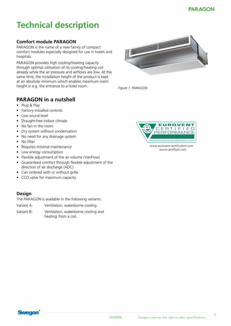
Figure 1. PARAGON
DesignThe PARAGON is available in the following variants:
Variant A: Ventilation, waterborne cooling.
Variant B: Ventilation, waterborne cooling and heating from a coil.
Comfort module PARAGONPARAGON is the name of a new family of compact comfort modules especially designed for use in hotels and hospitals.
PARAGON provides high cooling/heating capacity through optimal utilisation of its cooling/heating coil already while the air pressure and airflows are low. At the same time, the installation height of the product is kept at an absolute minimum which enables maximum room height in e.g. the entrance to a hotel room.
Technical description
www.eurovent-certification.com www.certiflash.com

PARAGON
4Swegon reserves the right to alter specifications. 20160818
Outstanding features of the PARAGON comfort moduleThe PARAGON has been developed for the purpose of creating an optimal indoor climate mainly in hotel rooms and hospital wards. Strong focus has been directed on a high degree of comfort as well as low running costs in these applications. Since the PARAGON is driven by a central air handling unit, there is no built-in fan that would otherwise generate noise and require servicing.
The Paragon product family includes the following variants:
PARAGON c A-HC High capacity Paragon for cooling only. The capacity of the heat exchanger is utilised optimally by maximising the cooling circuit through the coil.
• Lower energy consumption gives a lower operating cost and with that less environment impact.
• A smaller Paragon unit than before can be used, which results in a lower investment cost and more space for other installations
• The high output gives faster cooling of hotel rooms that have stood empty.
PARAGON c B-HC CCO Paragon B-HC CCO is a high capacity variant of Paragon where a CCO valve Compact Change Over is used to utilise the whole coil of both cooling and heating.
Advantages:
• Compact PARAGON unit with high output means simpler project planning.
• Smaller units can be used. Lower investment cost and less space needed.
• Faster conditioning of a room that has been left empty. High and consistent comfort
• Permits a higher cooling water temperature and lower heating water temperature, which gives lower operating costs for the chiller and heat pump, i.e. less environmental impact.
Room control system CONDUCTOR is used to control the CCO valve. For more information about the CCO valve, see the CCO prod-uct data sheet at www.swegon.se
PARAGON c B-NCNormal capacity Paragon with 4 tube coil, that is separate cooling and heating coils

520160818 Swegon reserves the right to alter specifications.
PARAGON
Basic function diagram
PARAGON
Hotel & HospitalThe primary air is supplied via duct connection in the rear edge of the unit and this builds up positive pressure inside the unit. The positive pressure distributes the primary air with relatively high velocity via two rows of nozzle holes, one row in the upper edge and one row in the lower edge of the outlet. The high velocity of the primary air creates negative pressure which generates induction of the room air. The recirculation air is sucked up through the recirculation grille of the unit and flows on through the coil where it is cooled, heated, if required, or just passes untreated, before it mixes with the primary air and is discharged into the room.
Figure 2 – PARAGON cooling function 1 = Primary air 2 = Induced room air 3 = Primary air mixed with chilled room air
Figure 3 – PARAGON heating function (waterborne) 1 = Primary air 2 = Induced room air 3 = Primary air mixed with heated room air
The supply air discharged into hotel rooms and hospital wards is advantageously distributed as straight as pos-sible by allowing it to follow the ceiling, i.e. utilising the Coanda effect. This enables the air to reach all the way to the perimeter wall. If horizontal air distribution is desir-able, this is simply achieved by means of the ADC (Anti Draught Control) feature, which is included as standard in all PARAGON comfort modules. If vertical air distribu-tion is desirable, this is achieved by setting the outlet grille vanes to slant upward or downward. If you like, you can lock the angle setting of the outlet grille using an acces-sory that secures the vanes in fixed position.
Figure 4 – Air distribution with the PARAGON in a hotel room
Figure 5 – Air distribution with the PARAGON in a hospital ward

PARAGON
6Swegon reserves the right to alter specifications. 20160818
Figure 8. Vertical air distribution with adjustable louvres in the supply air grille.Figure 6 – Horizontal air distribution with ADC
Figure 7. PARAGON ADC

720160818 Swegon reserves the right to alter specifications.
PARAGON
Figure 12. Adjustment of nozzles L, M and H (The throttling strip for nozzle H has been removed)
H
L
MFigure 9. Commissioning, nozzle, L
Figure 11. Commissioning, nozzle, H
Figure 10. Commissioning, nozzle, M
PARAGON
8Swegon reserves the right to alter specifications. 20160818
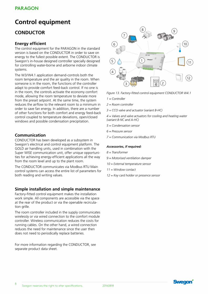
Energy efficientThe control equipment for the PARAGON in the standard version is based on the CONDUCTOR in order to save on energy to the fullest possible extent. The CONDUCTOR is Swegon’s in-house designed controller specially designed for controlling water-borne and airborne indoor climate systems.
The W3/W4.1 application demand-controls both the room temperature and the air quality in the room. When someone is in the room, the functions of the controller adapt to provide comfort feed-back control. If no one is in the room, the controls activate the economy comfort mode, allowing the room temperature to deviate more from the preset setpoint. At the same time, the system reduces the airflow to the relevant room to a minimum in order to save fan energy. In addition, there are a number of other functions for both comfort and energy feed-back control coupled to temperature deviations, open/closed windows and possible condensation precipitation.
CommunicationCONDUCTOR has been developed as a subsystem in Swegon’s electrical and control equipment platform. The GOLD air handling units, used in combination with the Super WISE communication unit, offer unique opportuni-ties for achieving energy-efficient applications all the way from the room level and up to the plant room.
The CONDUCTOR communicates via Modbus RTU Main control systems can access the entire list of parameters for both reading and writing values.
Simple installation and simple maintenanceFactory-fitted control equipment makes the installation work simple. All components are accessible via the space at the rear of the product or via the openable recircula-tion grille.
The room controller included in the supply communicates wirelessly or via wired connection to the comfort module controller. Wireless communication reduces the costs for running cables. On the other hand, a wired connection reduces the need for maintenance since the user then does not need to periodically replace batteries.
For more information regarding the CONDUCTOR, see separate product data sheet.
5
6
4
3 2
7
1
8 9
10
Figure 13. Factory-fitted control equipment CONDUCTOR W4.1
1 = Controller
2 = Room controller
3 = CCO valve and actuator (variant B-HC)
4 = Valves and valve actuators for cooling and heating water (variant B-NC and A-HC)
5 = Condensation sensor
6 = Pressure sensor
7 = Communication via Modbus RTU
Accessories, if required:
8 = Transformer
9 = Motorised ventilation damper
10 = External temperature sensor
11 = Window contact
12 = Key card holder or presence sensor
11
12
CONDUCTOR
Control equipment

920160818 Swegon reserves the right to alter specifications.
PARAGON
LUNA A simpler form of control equipment is available in appli-cations where the user does not want demand-controlled ventilation in the room and has no need of communica-tion with an external monitoring system. This variant of control is called the LUNA and regulates the temperature in the room only (not the air quality). The PARAGON with factory-fitted LUNA is available to order. Please note that the controller in this case is integrated into the room unit and requires a cable connection from the room to the actuator inside PARAGON. For more information, see the separate datasheet for the LUNA.
LUNA can not be used to control the CCO valve.
Figure 15. Factory-fitted control equipment LUNA
1 = Room controller with room thermostat
2 = Valves and valve actuators for cooling and heating water
3 = Condensation sensor
Accessories, if required:
4 = Transformer
5 = External temperature sensor
6 = Hand unit for changing the factory settings
1
4
6
3
5
2
PARAGON, along with the CONDUCTOR room control system, is the optimum solution for hotel rooms. CONDUCTOR is also used to control the CCO valve.
When the key card (or equivalent) is activated in the room, the airflow increases from the economical low flow to the normal flow, while the temperature adjusts to the comfort level.
When the room is empty, the ventilation and temperature return to economic low flow.
In addition to the automatic room control, the guest can manually adjust the temperature and airflow.
A more basic room control system LUNA can be used for hospital rooms and the like. The temperature can be regulated individually in each room, but the airflow is constant.
For more information about the CCO valve, see the CCO product data sheet at www.swegon.com
CCO6-way change over valve - CCOWith CCO - Compact Change Over, the same single circuit in the coil is used for both heating and cooling, providing maximum utilisation of the coil and thus a higher cooling and heating capacity.
Advantages:
• A higher cooling water temperature and lower heating water temperature give improved operating economy for the chiller and heat pump. Lower energy consump-tion gives lower operating cost and less environment impact.
• Smaller PARAGON units can be used. Lower invest-ment cost and less space needed.
• Faster conditioning of a hotel room that has been left unoccupied/empty. High and consistent comfort.
• Compact unit with high output means simpler project planning.
Figure 14. CCO 6-way valve

PARAGON
10Swegon reserves the right to alter specifications. 20160818
Project planningBoth planning and sizing are made easier by using Swegon’s ProSelect Project design computer program. ProSelect is available under software on the Swegon web-site: www.swegon.com.
SizingDesignations
P: Capacity (W, kW)
v: Velocity (m/s)
q: Flow (l/s)
p: Pressure, (Pa, kPa)
tr: Room temperature (°C)
tm: Mean water temperature (°C)
∆Tm: Temperature difference [tr - tm] (K)
∆T: Temperature difference, between inlet and return (K)
∆Tl: Temperature difference, between room and supply air (K)
∆p: Pressure drop (Pa, kPa)
kp: Pressure drop constantSupplementary index:
k = cooling, l = air, v = heating, i = commissioning
Recommended limit values, water
Max. recommended operating pressure (across coil only): 1600 kPa *
Max. recommended test pressure (across coil only): 2400 kPa * * Applicable without control equipment mounted
Max. recommended pressure drop across the CCO valve: 20 kPa
Max. recommended pressure drop across a standard valve: 20 kPa
Min. permissible hot water flow: 0.013 l/s
Max. permissible inlet flow temperature: 60 °C
Min. cooling water flow: 0.04 l/s
Lowest permissible inlet flow temperature: Should always be dimen-sioned so that the system works without condensation

1120160818 Swegon reserves the right to alter specifications.
PARAGON
Cooling Cooling capacityCooling capacities achieved from both the primary air and chilled water for various lengths of unit, damper settings and airflows are tabulated in Table 3-8. The total cooling capacity for one unit is the sum of the cooling capacity of the primary air and the chilled water.
The cooling capacity of the primary air can also be calcu-lated using the formula:
Pl = 1.2 · ql · ΔTl where Pl = Air’s cooling capacity (W) ql = Airflow (l/s) ∆Tl = Temperature difference (K)
Pressure drop
The pressure drop on the water side can be calculated using the formula:
∆p = (q / kpk)2 where
∆p = Pressure drop in the water circuit (kPa)
q = Water flow (l/s), see Diagram 1
kpk = Pressure drop constant read from table 1.
Diagram 1 – Cooling capacityThe function between cooling capacity Pk (W), change in temperature∆Tk (K) and the cooling water flow qk (l/s).
Capacity correctionDifferent water flows influence the available cooling effect to a certain degree. To calculate the actual cooling power based on a flow-dependant correction factor, use Swegon’s ProSelect computer program, available at www.swegon.com.
Table 2. Cooling capacity for natural convection
Natural convection: The cooling capacity of water at ∆Tmv
Size 5 6 7 8 9 10 11 12
775 14 20 26 34 42 51 60 71
900 17 24 32 40 50 61 72 85
1100 22 31 41 53 65 79 94 110
1300 31 42 53 65 79 93 108 124
1500 40 52 64 78 92 107 122 138
Diagram 2. Water flow – capacity correction
0,70
0,75
0,80
0,85
0,90
0,95
1,00
1,05
1,10
0,03 0,04 0,05 0,06 0,07 0,08 0,09 q (l/s)
k
Table 1. Pressure drop, water
NC HC HC CCO
Length Kpk Cooling Kpk Cooling Kpk Cooling
775 0.0250 0.0178 0.0178
900 0.0231 0.0170 0.0170
1100 0.0215 0.0161 0.0161
1300 0.0205 0.0154 0.0154
1500 0.0194 0.0145 0.0145
NC - Normal design HC - High Capacity design HC - High Capacity design with CCO valve
PARAGON
12Swegon reserves the right to alter specifications. 20160818
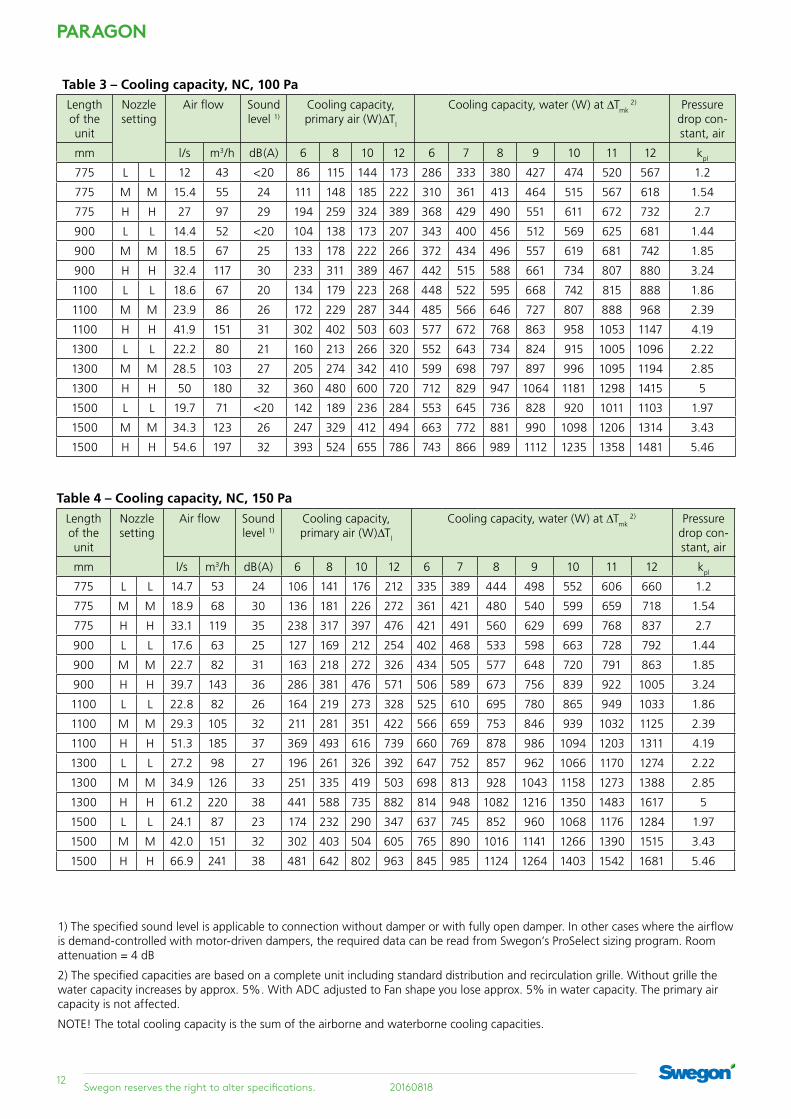
1) The specified sound level is applicable to connection without damper or with fully open damper. In other cases where the airflow is demand-controlled with motor-driven dampers, the required data can be read from Swegon’s ProSelect sizing program. Room attenuation = 4 dB
2) The specified capacities are based on a complete unit including standard distribution and recirculation grille. Without grille the water capacity increases by approx. 5%. With ADC adjusted to Fan shape you lose approx. 5% in water capacity. The primary air capacity is not affected.
NOTE! The total cooling capacity is the sum of the airborne and waterborne cooling capacities.
Table 3 – Cooling capacity, NC, 100 PaLength of the unit
Nozzle setting
Air flow Sound level 1)
Cooling capacity, primary air (W)∆Tl
Cooling capacity, water (W) at ∆Tmk 2) Pressure
drop con-stant, air
mm l/s m3/h dB(A) 6 8 10 12 6 7 8 9 10 11 12 kpl
775 L L 12 43 <20 86 115 144 173 286 333 380 427 474 520 567 1.2
775 M M 15.4 55 24 111 148 185 222 310 361 413 464 515 567 618 1.54
775 H H 27 97 29 194 259 324 389 368 429 490 551 611 672 732 2.7
900 L L 14.4 52 <20 104 138 173 207 343 400 456 512 569 625 681 1.44
900 M M 18.5 67 25 133 178 222 266 372 434 496 557 619 681 742 1.85
900 H H 32.4 117 30 233 311 389 467 442 515 588 661 734 807 880 3.24
1100 L L 18.6 67 20 134 179 223 268 448 522 595 668 742 815 888 1.86
1100 M M 23.9 86 26 172 229 287 344 485 566 646 727 807 888 968 2.39
1100 H H 41.9 151 31 302 402 503 603 577 672 768 863 958 1053 1147 4.19
1300 L L 22.2 80 21 160 213 266 320 552 643 734 824 915 1005 1096 2.22
1300 M M 28.5 103 27 205 274 342 410 599 698 797 897 996 1095 1194 2.85
1300 H H 50 180 32 360 480 600 720 712 829 947 1064 1181 1298 1415 5
1500 L L 19.7 71 <20 142 189 236 284 553 645 736 828 920 1011 1103 1.97
1500 M M 34.3 123 26 247 329 412 494 663 772 881 990 1098 1206 1314 3.43
1500 H H 54.6 197 32 393 524 655 786 743 866 989 1112 1235 1358 1481 5.46
Table 4 – Cooling capacity, NC, 150 Pa
Length of the unit
Nozzle setting
Air flow Sound level 1)
Cooling capacity, primary air (W)∆Tl
Cooling capacity, water (W) at ∆Tmk 2) Pressure
drop con-stant, air
mm l/s m3/h dB(A) 6 8 10 12 6 7 8 9 10 11 12 kpl
775 L L 14.7 53 24 106 141 176 212 335 389 444 498 552 606 660 1.2
775 M M 18.9 68 30 136 181 226 272 361 421 480 540 599 659 718 1.54
775 H H 33.1 119 35 238 317 397 476 421 491 560 629 699 768 837 2.7
900 L L 17.6 63 25 127 169 212 254 402 468 533 598 663 728 792 1.44
900 M M 22.7 82 31 163 218 272 326 434 505 577 648 720 791 863 1.85
900 H H 39.7 143 36 286 381 476 571 506 589 673 756 839 922 1005 3.24
1100 L L 22.8 82 26 164 219 273 328 525 610 695 780 865 949 1033 1.86
1100 M M 29.3 105 32 211 281 351 422 566 659 753 846 939 1032 1125 2.39
1100 H H 51.3 185 37 369 493 616 739 660 769 878 986 1094 1203 1311 4.19
1300 L L 27.2 98 27 196 261 326 392 647 752 857 962 1066 1170 1274 2.22
1300 M M 34.9 126 33 251 335 419 503 698 813 928 1043 1158 1273 1388 2.85
1300 H H 61.2 220 38 441 588 735 882 814 948 1082 1216 1350 1483 1617 5
1500 L L 24.1 87 23 174 232 290 347 637 745 852 960 1068 1176 1284 1.97
1500 M M 42.0 151 32 302 403 504 605 765 890 1016 1141 1266 1390 1515 3.43
1500 H H 66.9 241 38 481 642 802 963 845 985 1124 1264 1403 1542 1681 5.46

1320160818 Swegon reserves the right to alter specifications.
PARAGON
Table 5 – Cooling capacity, NC, 200 Pa
Length of the unit
Nozzle setting
Air flow Sound level 1)
Cooling capacity, pri-mary air (W)∆Tl
Cooling capacity, water (W) at ∆Tmk 2) Pressure
drop con-stant, air
mm l/s m3/h dB(A) 6 8 10 12 6 7 8 9 10 11 12 kpl
775 L L 17.0 61 28 122 163 204 244 370 429 489 548 607 666 725 1.2
775 M M 21.8 78 34 157 209 261 314 398 463 528 594 659 724 789 1.54
775 H H 38.2 137 40 275 367 458 550 459 534 610 685 761 836 911 2.7
900 L L 20.4 73 29 147 196 244 293 444 516 587 658 730 800 871 1.44
900 M M 26.2 94 35 188 251 314 377 477 556 635 713 792 870 948 1.85
900 H H 45.8 165 40 330 440 550 660 551 642 733 823 913 1004 1094 3.24
1100 L L 26.3 95 30 189 253 316 379 579 673 766 859 952 1044 1136 1.86
1100 M M 33.8 122 36 243 324 406 487 623 725 828 930 1033 1135 1237 2.39
1100 H H 59.3 213 42 427 569 711 853 719 837 956 1074 1192 1309 1427 4.19
1300 L L 31.4 113 31 226 301 377 452 714 830 945 1059 1174 1288 1401 2.22
1300 M M 40.3 145 37 290 387 484 580 768 895 1021 1147 1273 1399 1525 2.85
1300 H H 70.7 255 43 509 679 849 1018 887 1033 1179 1324 1470 1615 1760 5
1500 L L 27.9 100 27 201 267 334 401 697 816 935 1054 1174 1293 1413 1.97
1500 M M 48.5 175 37 349 466 582 699 837 974 1111 1248 1384 1521 1657 3.43
1500 H H 77.2 278 42 556 741 927 1112 918 1069 1220 1371 1522 1672 1823 5.46
Table 6 – Cooling capacity, HC, 100 Pa
Length of the unit
Nozzle setting
Air flow Sound level 1)
Cooling capacity, primary air (W)∆Tl
Cooling capacity, water (W) at ∆Tmk 2) Pressure
drop con-stant, air
mm l/s m3/h dB(A) 6 8 10 12 6 7 8 9 10 11 12 kpl
775 L L 12 43 <20 86 115 144 173 310 362 414 467 519 571 623 1.2
775 M M 15.4 55 24 111 148 185 222 340 397 454 510 568 625 682 1.54
775 H H 27 97 29 194 259 324 389 409 478 547 616 685 754 823 2.7
900 L L 14.4 52 <20 104 138 173 207 373 435 498 560 623 686 748 1.44
900 M M 18.5 67 25 133 178 222 266 408 476 545 613 682 750 819 1.85
900 H H 32.4 117 30 233 311 389 467 491 574 657 740 822 905 989 3.24
1100 L L 18.6 67 20 134 179 223 268 486 568 649 731 813 894 976 1.86
1100 M M 23.9 86 26 172 229 287 344 532 621 711 800 889 979 1068 2.39
1100 H H 41.9 151 31 302 402 503 603 641 749 857 965 1073 1181 1289 4.19
1300 L L 22.2 80 21 160 213 266 320 600 700 801 902 1002 1103 1204 2.22
1300 M M 28.5 103 27 205 274 342 410 656 766 876 986 1097 1207 1317 2.85
1300 H H 50 180 32 360 480 600 720 790 923 1056 1190 1323 1457 1590 5
1500 L L 19.7 71 <20 142 189 236 284 623 727 831 936 1040 1145 1249 1.97
1500 M M 34.3 123 26 247 329 412 494 745 869 993 1117 1241 1365 1489 3.43
1500 H H 54.6 197 32 393 524 655 786 859 999 1139 1278 1417 1556 1694 5.46
1) The specified sound level is applicable to connection without damper or with fully open damper. In other cases where the airflow is demand-controlled with motor-driven dampers, the required data can be read from Swegon’s ProSelect sizing program. Room attenuation = 4 dB
2) The specified capacities are based on a complete unit including standard distribution and recirculation grille. Without grille the water capacity increases by approx. 5%. With ADC adjusted to Fan shape you lose approx. 5% in water capacity. The primary air capacity is not affected.
NOTE! The total cooling capacity is the sum of the airborne and waterborne cooling capacities.

PARAGON
14Swegon reserves the right to alter specifications. 20160818
Table 7 – Cooling capacity, HC, 150 Pa
Length of the unit
Nozzle setting
Air flow Sound level 1)
Cooling capacity, primary air (W)∆Tl
Cooling capacity, water (W) at ∆Tmk 2) Pressure
drop con-stant, air
mm l/s m3/h dB(A) 6 8 10 12 6 7 8 9 10 11 12 kpl
775 L L 14.7 53 24 106 141 176 212 364 426 487 549 611 674 736 1.2
775 M M 18.9 68 30 136 181 226 272 395 462 529 596 664 731 798 1.54
775 H H 33.1 119 35 238 317 397 476 469 549 629 709 790 870 951 2.7
900 L L 17.6 63 25 127 169 212 254 437 511 586 660 734 809 884 1.44
900 M M 22.7 82 31 163 218 272 326 475 555 636 716 797 878 959 1.85
900 H H 39.7 143 36 286 381 476 571 563 659 755 852 948 1045 1142 3.24
1100 L L 22.8 82 26 164 219 273 328 570 667 764 861 958 1055 1153 1.86
1100 M M 29.3 105 32 211 281 351 422 619 724 829 934 1040 1145 1251 2.39
1100 H H 51.3 185 37 369 493 616 739 735 860 985 1111 1237 1363 1490 4.19
1300 L L 27.2 98 27 196 261 326 392 703 823 942 1062 1181 1302 1422 2.22
1300 M M 34.9 126 33 251 335 419 503 764 893 1022 1152 1282 1412 1543 2.85
1300 H H 61.2 220 38 441 588 735 882 906 1060 1215 1370 1526 1682 1838 5
1500 L L 24.1 87 23 174 232 290 347 730 852 975 1098 1221 1343 1466 1.97
1500 M M 42.0 151 32 302 403 504 605 869 1013 1157 1301 1445 1588 1732 3.43
1500 H H 66.9 241 38 481 642 802 963 988 1147 1305 1462 1619 1775 1930 5.46
Table 8 – Cooling capacity, HC, 200 Pa
Length of the unit
Nozzle setting
Air flow Sound level 1)
Cooling capacity, pri-mary air (W)∆Tl
Cooling capacity, water (W) at ∆Tmk 2) Pressure
drop con-stant, air
mm l/s m3/h dB(A) 6 8 10 12 6 7 8 9 10 11 12 kpl
775 L L 17.0 61 28 122 163 204 244 402 471 539 608 677 746 816 1.2
775 M M 21.8 78 34 157 209 261 314 434 509 583 657 732 806 881 1.54
775 H H 38.2 137 40 275 367 458 550 511 599 687 775 864 953 1042 2.7
900 L L 20.4 73 29 147 196 244 293 483 565 648 730 813 897 980 1.44
900 M M 26.2 94 35 188 251 314 377 522 611 700 789 879 969 1059 1.85
900 H H 45.8 165 40 330 440 550 660 614 720 825 931 1038 1144 1251 3.24
1100 L L 26.3 95 30 189 253 316 379 630 737 845 953 1061 1169 1278 1.86
1100 M M 33.8 122 36 243 324 406 487 681 797 913 1030 1146 1263 1381 2.39
1100 H H 59.3 213 42 427 569 711 853 801 939 1077 1215 1354 1493 1632 4.19
1300 L L 31.4 113 31 226 301 377 452 777 909 1042 1175 1309 1442 1576 2.22
1300 M M 40.3 145 37 290 387 484 580 840 983 1126 1270 1414 1558 1703 2.85
1300 H H 70.7 255 43 509 679 849 1018 988 1158 1328 1498 1670 1841 2013 5
1500 L L 27.9 100 27 201 267 334 401 806 941 1077 1213 1349 1485 1621 1.97
1500 M M 48.5 175 37 349 466 582 699 957 1116 1273 1431 1589 1746 1904 3.43
1500 H H 77.2 278 42 556 741 927 1112 1081 1252 1423 1593 1762 1930 2098 5.46
1) The specified sound level is applicable to connection without damper or with fully open damper. In other cases where the airflow is demand-controlled with motor-driven dampers, the required data can be read from Swegon’s ProSelect sizing program. Room attenuation = 4 dB
2) The specified capacities are based on a complete unit including standard distribution and recirculation grille. Without grille the water capacity increases by approx. 5%. With ADC adjusted to Fan shape you lose approx. 5% in water capacity. The primary air capacity is not affected.
NOTE! The total cooling capacity is the sum of the airborne and waterborne cooling capacities.
1520160818 Swegon reserves the right to alter specifications.
PARAGON
Heating
Pressure dropThe pressure drop on the water side can be calculated using the formula:
∆p = (q / kpv)2 where
∆p = Pressure drop in the water circuit (kPa)
q = Water flow (l/s), see Diagram 3
kpk = Pressure drop constant read from table 9.
For a more detailed pressure drop calculation, use the Swegon’s ProSelect software, which is available on www.swegon.com.
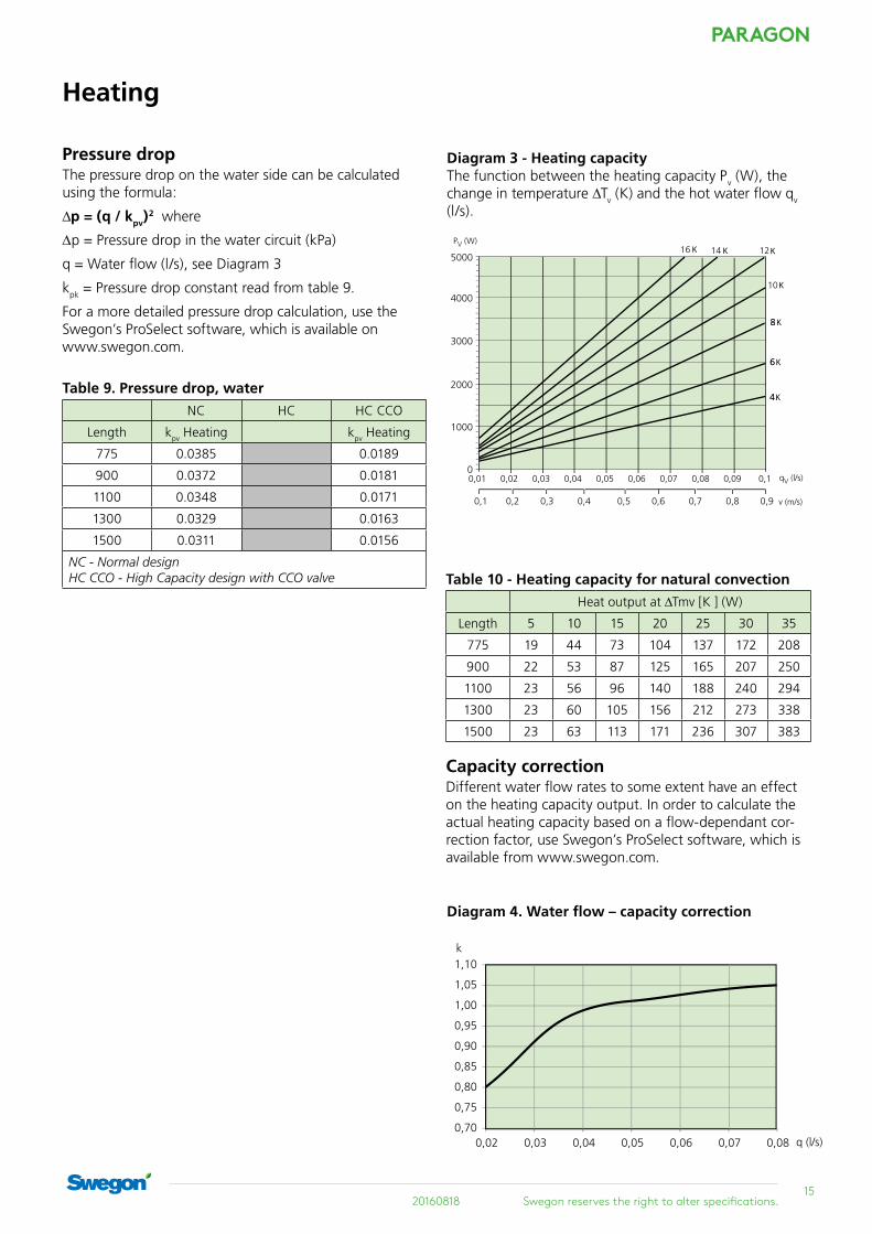
Diagram 3 - Heating capacityThe function between the heating capacity Pv (W), the change in temperature ∆Tv (K) and the hot water flow qv (l/s).
Table 10 - Heating capacity for natural convection
Heat output at ∆Tmv [K ] (W)
Length 5 10 15 20 25 30 35
775 19 44 73 104 137 172 208
900 22 53 87 125 165 207 250
1100 23 56 96 140 188 240 294
1300 23 60 105 156 212 273 338
1500 23 63 113 171 236 307 383
Capacity correctionDifferent water flow rates to some extent have an effect on the heating capacity output. In order to calculate the actual heating capacity based on a flow-dependant cor-rection factor, use Swegon’s ProSelect software, which is available from www.swegon.com.
Table 9. Pressure drop, water
NC HC HC CCO
Length kpv Heating kpv Heating
775 0.0385 0.0189
900 0.0372 0.0181
1100 0.0348 0.0171
1300 0.0329 0.0163
1500 0.0311 0.0156
NC - Normal design HC CCO - High Capacity design with CCO valve
Diagram 4. Water flow – capacity correction
0,70
0,75
0,80
0,85
0,90
0,95
1,00
1,05
1,10
0,02 0,03 0,04 0,05 0,06 0,07 0,08 q (l/s)
k
PARAGON
16Swegon reserves the right to alter specifications. 20160818
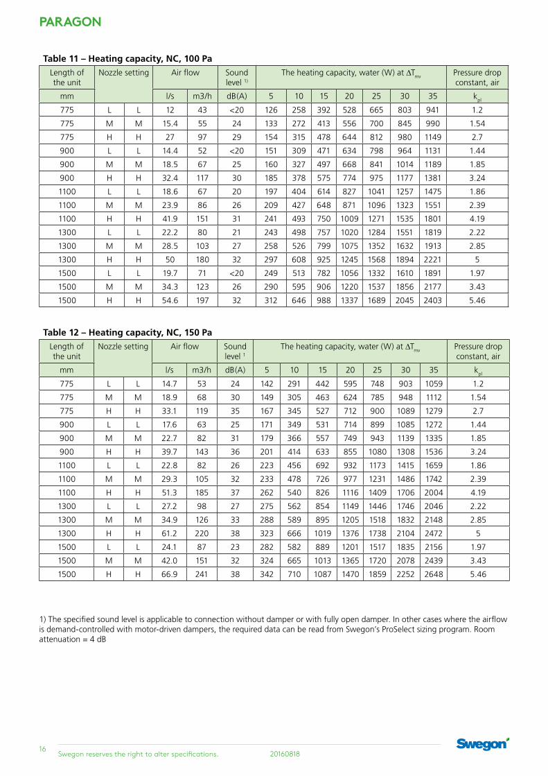
Table 11 – Heating capacity, NC, 100 PaLength of the unit
Nozzle setting Air flow Sound level 1)
The heating capacity, water (W) at ∆Tmv Pressure drop constant, air
mm l/s m3/h dB(A) 5 10 15 20 25 30 35 kpl
775 L L 12 43 <20 126 258 392 528 665 803 941 1.2
775 M M 15.4 55 24 133 272 413 556 700 845 990 1.54
775 H H 27 97 29 154 315 478 644 812 980 1149 2.7
900 L L 14.4 52 <20 151 309 471 634 798 964 1131 1.44
900 M M 18.5 67 25 160 327 497 668 841 1014 1189 1.85
900 H H 32.4 117 30 185 378 575 774 975 1177 1381 3.24
1100 L L 18.6 67 20 197 404 614 827 1041 1257 1475 1.86
1100 M M 23.9 86 26 209 427 648 871 1096 1323 1551 2.39
1100 H H 41.9 151 31 241 493 750 1009 1271 1535 1801 4.19
1300 L L 22.2 80 21 243 498 757 1020 1284 1551 1819 2.22
1300 M M 28.5 103 27 258 526 799 1075 1352 1632 1913 2.85
1300 H H 50 180 32 297 608 925 1245 1568 1894 2221 5
1500 L L 19.7 71 <20 249 513 782 1056 1332 1610 1891 1.97
1500 M M 34.3 123 26 290 595 906 1220 1537 1856 2177 3.43
1500 H H 54.6 197 32 312 646 988 1337 1689 2045 2403 5.46
Table 12 – Heating capacity, NC, 150 PaLength of the unit
Nozzle setting Air flow Sound level 1
The heating capacity, water (W) at ∆Tmv Pressure drop constant, air
mm l/s m3/h dB(A) 5 10 15 20 25 30 35 kpl
775 L L 14.7 53 24 142 291 442 595 748 903 1059 1.2
775 M M 18.9 68 30 149 305 463 624 785 948 1112 1.54
775 H H 33.1 119 35 167 345 527 712 900 1089 1279 2.7
900 L L 17.6 63 25 171 349 531 714 899 1085 1272 1.44
900 M M 22.7 82 31 179 366 557 749 943 1139 1335 1.85
900 H H 39.7 143 36 201 414 633 855 1080 1308 1536 3.24
1100 L L 22.8 82 26 223 456 692 932 1173 1415 1659 1.86
1100 M M 29.3 105 32 233 478 726 977 1231 1486 1742 2.39
1100 H H 51.3 185 37 262 540 826 1116 1409 1706 2004 4.19
1300 L L 27.2 98 27 275 562 854 1149 1446 1746 2046 2.22
1300 M M 34.9 126 33 288 589 895 1205 1518 1832 2148 2.85
1300 H H 61.2 220 38 323 666 1019 1376 1738 2104 2472 5
1500 L L 24.1 87 23 282 582 889 1201 1517 1835 2156 1.97
1500 M M 42.0 151 32 324 665 1013 1365 1720 2078 2439 3.43
1500 H H 66.9 241 38 342 710 1087 1470 1859 2252 2648 5.46
1) The specified sound level is applicable to connection without damper or with fully open damper. In other cases where the airflow is demand-controlled with motor-driven dampers, the required data can be read from Swegon’s ProSelect sizing program. Room attenuation = 4 dB

1720160818 Swegon reserves the right to alter specifications.
PARAGON
Table 13 – Heating capacity, NC, 200 PaLength of the unit
Nozzle setting Air flow Sound level 1)
The heating capacity, water (W) at ∆Tmv Pressure drop constant, air
mm l/s m3/h dB(A) 5 10 15 20 25 30 35 kpl
775 L L 17.0 61 28 154 315 478 642 808 975 1142 1.2
775 M M 21.8 78 34 160 328 499 672 846 1022 1198 1.54
775 H H 38.2 137 40 177 366 562 760 962 1166 1371 2.7
900 L L 20.4 73 29 185 378 574 771 970 1171 1372 1.44
900 M M 26.2 94 35 192 394 599 807 1016 1227 1439 1.85
900 H H 45.8 165 40 212 440 675 913 1155 1400 1647 3.24
1100 L L 26.3 95 30 241 493 748 1006 1266 1527 1790 1.86
1100 M M 33.8 122 36 251 514 782 1052 1326 1601 1877 2.39
1100 H H 59.3 213 42 277 574 880 1191 1507 1826 2149 4.19
1300 L L 31.4 113 31 298 608 923 1241 1561 1884 2208 2.22
1300 M M 40.3 145 37 309 634 964 1298 1635 1974 2316 2.85
1300 H H 70.7 255 43 341 708 1085 1469 1859 2253 2650 5
1500 L L 27.9 100 27 305 631 965 1304 1648 1995 2345 1.97
1500 M M 48.5 175 37 348 714 1089 1467 1850 2236 2624 3.43
1500 H H 77.2 278 42 364 755 1156 1566 1980 2399 2822 5.46
Table 14 – Heating capacity, HC, 100 PaLength of the unit
Nozzle setting Air flow Sound level 1)
The heating capacity, water (W) at ∆Tmv Pressure drop constant, air
mm l/s m3/h dB(A) 5 10 15 20 25 30 35 kpl
775 L L 12 43 <20 232 470 710 950 1192 1435 1678 1.2
775 M M 15.4 55 24 266 534 804 1074 1345 1617 1888 1.54
775 H H 27 97 29 309 628 950 1274 1600 1927 2255 2.7
900 L L 14.4 52 <20 279 565 852 1141 1432 1723 2015 1.44
900 M M 18.5 67 25 319 641 965 1290 1616 1942 2268 1.85
900 H H 32.4 117 30 372 754 1141 1530 1921 2314 2709 3.24
1100 L L 18.6 67 20 364 736 1112 1489 1868 2248 2629 1.86
1100 M M 23.9 86 26 416 837 1259 1683 2108 2533 2959 2.39
1100 H H 41.9 151 31 485 984 1488 1996 2506 3019 3533 4.19
1300 L L 22.2 80 21 449 908 1371 1836 2303 2772 3242 2.22
1300 M M 28.5 103 27 513 1032 1553 2076 2600 3124 3649 2.85
1300 H H 50 180 32 598 1213 1835 2461 3091 3723 4358 5
1500 L L 19.7 71 <20 472 942 1413 1883 2354 2824 3294 1.97
1500 M M 34.3 123 26 578 1154 1731 2307 2883 3459 4035 3.43
1500 H H 54.6 197 32 658 1317 1977 2638 3299 3960 4622 5.46
1) The specified sound level is applicable to connection without damper or with fully open damper. In other cases where the airflow is demand-controlled with motor-driven dampers, the required data can be read from Swegon’s ProSelect sizing program. Room attenuation = 4 dB
PARAGON
18Swegon reserves the right to alter specifications. 20160818
1) The specified sound level is applicable to connection without damper or with fully open damper. In other cases where the airflow is demand-controlled with motor-driven dampers, the required data can be read from Swegon’s ProSelect sizing program. Room attenuation = 4 dB
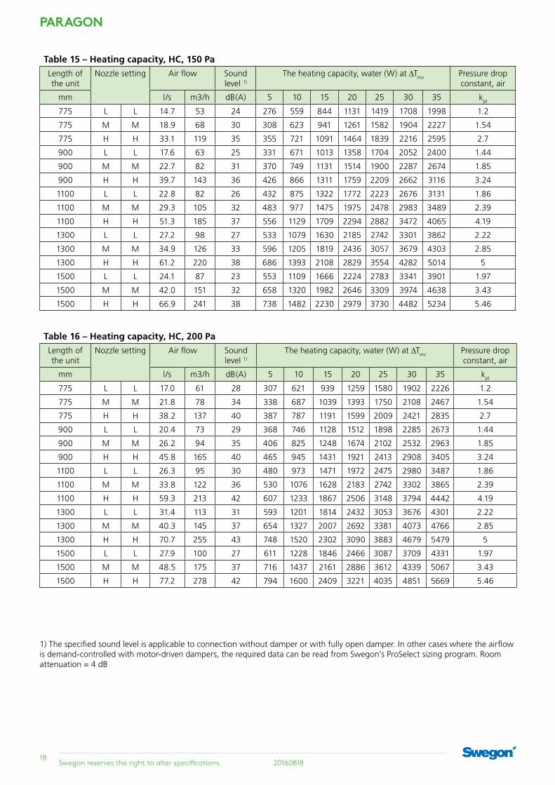
Table 15 – Heating capacity, HC, 150 PaLength of the unit
Nozzle setting Air flow Sound level 1)
The heating capacity, water (W) at ∆Tmv Pressure drop constant, air
mm l/s m3/h dB(A) 5 10 15 20 25 30 35 kpl
775 L L 14.7 53 24 276 559 844 1131 1419 1708 1998 1.2
775 M M 18.9 68 30 308 623 941 1261 1582 1904 2227 1.54
775 H H 33.1 119 35 355 721 1091 1464 1839 2216 2595 2.7
900 L L 17.6 63 25 331 671 1013 1358 1704 2052 2400 1.44
900 M M 22.7 82 31 370 749 1131 1514 1900 2287 2674 1.85
900 H H 39.7 143 36 426 866 1311 1759 2209 2662 3116 3.24
1100 L L 22.8 82 26 432 875 1322 1772 2223 2676 3131 1.86
1100 M M 29.3 105 32 483 977 1475 1975 2478 2983 3489 2.39
1100 H H 51.3 185 37 556 1129 1709 2294 2882 3472 4065 4.19
1300 L L 27.2 98 27 533 1079 1630 2185 2742 3301 3862 2.22
1300 M M 34.9 126 33 596 1205 1819 2436 3057 3679 4303 2.85
1300 H H 61.2 220 38 686 1393 2108 2829 3554 4282 5014 5
1500 L L 24.1 87 23 553 1109 1666 2224 2783 3341 3901 1.97
1500 M M 42.0 151 32 658 1320 1982 2646 3309 3974 4638 3.43
1500 H H 66.9 241 38 738 1482 2230 2979 3730 4482 5234 5.46
Table 16 – Heating capacity, HC, 200 PaLength of the unit
Nozzle setting Air flow Sound level 1)
The heating capacity, water (W) at ∆Tmv Pressure drop constant, air
mm l/s m3/h dB(A) 5 10 15 20 25 30 35 kpl
775 L L 17.0 61 28 307 621 939 1259 1580 1902 2226 1.2
775 M M 21.8 78 34 338 687 1039 1393 1750 2108 2467 1.54
775 H H 38.2 137 40 387 787 1191 1599 2009 2421 2835 2.7
900 L L 20.4 73 29 368 746 1128 1512 1898 2285 2673 1.44
900 M M 26.2 94 35 406 825 1248 1674 2102 2532 2963 1.85
900 H H 45.8 165 40 465 945 1431 1921 2413 2908 3405 3.24
1100 L L 26.3 95 30 480 973 1471 1972 2475 2980 3487 1.86
1100 M M 33.8 122 36 530 1076 1628 2183 2742 3302 3865 2.39
1100 H H 59.3 213 42 607 1233 1867 2506 3148 3794 4442 4.19
1300 L L 31.4 113 31 593 1201 1814 2432 3053 3676 4301 2.22
1300 M M 40.3 145 37 654 1327 2007 2692 3381 4073 4766 2.85
1300 H H 70.7 255 43 748 1520 2302 3090 3883 4679 5479 5
1500 L L 27.9 100 27 611 1228 1846 2466 3087 3709 4331 1.97
1500 M M 48.5 175 37 716 1437 2161 2886 3612 4339 5067 3.43
1500 H H 77.2 278 42 794 1600 2409 3221 4035 4851 5669 5.46

1920160818 Swegon reserves the right to alter specifications.
PARAGON
Acoustics
Natural attenuationNatural attenuation is the total reduction in sound power from duct to room including the end reflection of the unit.
Table 17. Natural attenuation with cladding
Natural attenuation (dB) at mid frequency f (Hz) ∆Lw [dB ]
63 125 250 500 1k 2k 4k 8k
24 14 9 6 9 14 14 18

PARAGON
20Swegon reserves the right to alter specifications. 20160818
AccessoriesSupply air kit – PARAGON T-SAK-VAVA motor-driven damper is needed in applications where the user wants to demand-control the supply air by means of CONDUCTOR control equipment The damper causes a certain amount of flow-generated sound. There-fore a sound attenuator is also needed to guarantee a low sound level in the room. The following components are included in PARAGON T-SAK-VAV:
Motor-driven damper
CRTc including Swegon motor
Sound attenuator CLA rectangular sound attenuator with circular connection spigots L=500mm
Figure 16. PARAGON T-SAK-VAV
Supply air kit – PARAGON T-SAK-CAVA commissioning damper is needed to ensure the correct airflow if a simpler feed-back control system with con-stant airflow has been selected. Commissioning dampers also generate a certain amount of sound. We therefore recommend the use of a sound attenuator for keeping the sound level at a minimum. The following components are included in PARAGON T-SAK-CAV:
Commissioning damper
CRPc-9 Commissioning damper with perforated damper blade and manually adjustable blade
Sound attenuator CLA rectangular sound attenua-tor with circular connection spigots L=500mm
Figure 17. PARAGON T-SAK-CAV
Sound attenuator
Motor-driven damper
Commissioning damper
Sound attenuator
Extract air kit – PARAGON T-EAK-CAVA commissioning damper is needed in systems with con-stant airflows in order to balance the extract airflow with the supply airflow.
Therefore a kit designed for constant airflows is avail-able for simpler systems. This kit contains commissioning damper, sound attenuator, extract air register and mount-ing frames.
Commissioning damper
CRPc-9 Commissioning damper with perfo-rated damper blade and manually adjust-able blade
Sound attenuator
CLA rectangular sound attenuator with circular connection spigots L=500mm
Extract air register
EXCa and accompanying mounting frames: One with a nipple and one with a joint
Figure 19. Extract air kit PARAGON T-EAK-CAV
Extract air kit – PARAGON T-EAK-VAVIf the supply air is demand-controlled, the extract air also needs to be feed-back controlled. An extract air kit is needed for balancing the supply air and the extract air. Precisely like the supply air kit, this kit consists of a motor-driven damper and a sound attenuator. In addition an extract air register and two alternative mounting frames are included: one with a nipple and one with a joint.
Motor-driven damper
CRTc including Swegon motor
Sound attenuator
CLA rectangular sound attenuator with circular connection spigots L=500mm
Extract air register
EXCa and accompanying mounting frames: one with a nipple and one with a joint
Figure 18. Extract air kit – PARAGON T-EAK-VAV
Motor-driven damper
Sound attenuator
Extract air register
Commissioning damper
Sound attenuator
Extract air register

2120160818 Swegon reserves the right to alter specifications.
PARAGON
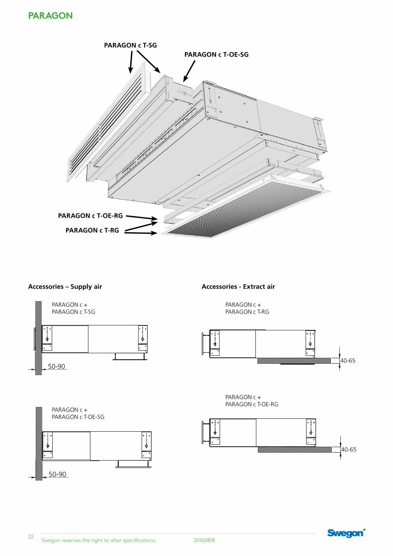
Accessories – Supply air Accessories - Return airA supply air grille with a telescopic spigot that covers an interval of 50 - 90 mm is supplied as standard.The grille is supplied as standard in RAL 9003. Other colours are available on request.
The return air grille is supplied with telescopic spigot/frame which can be inserted into the module and which then covers the 40-65 mm interval between the module and the ceiling.The return air grille is supplied as standard in RAL 9003. Avail-able in other colours on request.
PARAGON c T-SG
Telescopic supply air grille 50-90 mm spigot
PARAGON c T-RG
Telescopic Return air grille 40-65 mm spigot
PARAGON c T-OE-SG PARAGON c T-OE-RGFor selection of another grille, only spigots for the supply air grille can be ordered. Spigot dimensions 50-90 mm
For selection of another grille, only spigots for the return air grille can be ordered. Spigot dimensions 40-65 mm
PARAGON
22Swegon reserves the right to alter specifications. 20160818
Accessories – Supply air
PARAGON c + PARAGON c T-SG
PARAGON c + PARAGON c T-OE-SG
Accessories - Extract air
PARAGON c + PARAGON c T-RG
40-65
PARAGON c + PARAGON c T-OE-RG
40-65
50-90
50-90
PARAGON c T-SGPARAGON c T-OE-SG
PARAGON c T-RG
PARAGON c T-OE-RG

2320160818 Swegon reserves the right to alter specifications.
PARAGON
Suspension kit SYST MS M8
In the applications in which the PARAGON is not mounted in direct contact with the ceiling, there is a suspension kit available in order to simplify hanging it at the level desired.
Figure 20. Suspension kit SYST MS M8
Flexible hoses
In applications in which you desire to avoid risk of move-ment in the pipe system caused by heat expansion, you can advantageously utilize flexible hoses for the connec-tion of chilled water and hot water. Eventual vibrations via the pipe system are at the same time diminished to an absolute minimum.
Figure 21. Flexible connection hose, SYST FH
Venting nipple
A venting nipple with push-on connection can be utilised in combination with type SYST FS F20 flexible hoses. This is normally not needed, but can be an option if the coil in the PARAGON is the highest point on the water loop.
Figure 22. Bleed nipple SYST AR
Figure 23. Paragon T- GL. Grille lock for fixing the position of the supply air grille.
SMST1.asm
F1
F20
F30

PARAGON
24Swegon reserves the right to alter specifications. 20160818
Figure 24. PARAGON c B-HC with factory-fitted Conductor W4.1 controller including 2 pressure sensor room units RU and CCO valve for cooling and heating. Connection on the right hand side –R. See other options in the table below.
Table 18. Factory-fitted accessories All the options below and all the possible combinations of the same can be sized in ProSelect.
Conductor RE W1 controller incl. RU room unit
Conductor RE W3 controller incl. RU room unit
Conductor RE W4.1 controller incl. RU room unit and mounted pressure sensor for supply air.
LUNA controller (extra wiring terminals are fitted; the controller is packaged together with the module)
SYST VEN115 straight valve
Straight valve SYST VEN115 + ACTUATOR b 24V NC actuator wired to terminals
Only ACTUATOR b 24V NC actuator wired to terminals
Condensation sensor, WCD2 proactive condensation control, wired to terminals
Condensation sensor, CG-IV reactive condensation control, wired to terminals
Temperature sensor, wired to terminals (Only in combination with Conductor RE)
ProSelectProSelect is Swegon's sizing program which is available at www.swegon.com.
Several options and combinations can be sized in ProSe-lect.
The factory-fitted control equipment described in Figure 46 is shown below as an example.
Factory-fitted accessories
2520160818 Swegon reserves the right to alter specifications.
PARAGON
InstallationInstallationThe PARAGON is delivered with four mounting brackets designed for installation directly against the ceiling or installation suspended from the ceiling. The mounting brackets allow a certain amount of further adjustment after the comfort module/ceiling mounting brackets has/have been mounted as accurately as possible. This enables you to position the supply spigot correctly in relation to the wall and the grille. The next step is to connect the air duct, cooling pipes, heating pipes and power supply (24 V AC) to the control equipment. The motor dampers are directly connected to the controller in the PARAGON, if a supply air kit and an extract air kit are included in the installation. The SYST MS M8 suspension kit (must be ordered separately) can be used to advantage in applica-tions in which the PARAGON should not be mounted tight against the ceiling. For detailed mounting instruc-tions, see separate document available for downloading at www.swegon.com.
Water connectionsIf the PARAGON is supplied with factory-fitted control equipment, the supply water (cooling and heating) is con-nected to a flat pipe end Ø 12 x 1.0 mm (Cu). The return water (cooling and heating) should be connected to the valves, DN ½" male threads.
If the PARAGON is supplied with factory-fitted control equipment and CCO valve, the supply water (cooling and heating) is connected to a flat pipe end Ø 12 x 1.0 mm (Cu). The return water (cooling and heating) is also con-nected to a flat pipe end Ø 12 x 1.0 mm (Cu).
If the PARAGON is supplied without control equipment, all the pipes (supply/return – cooling/heating) are con-nected to a flat pipe end Ø 12 x 1.0 mm (Cu).
NOTE! Support sleeves must be used if compression ring cou-plings are fitted. It is important use a pipe wrench to adequately restrain the pipe connections when tightening external connec-tions to prevent damage to the connection pipes.
Air connectionA Ø 125 mm air duct including gasket should be con-nected directly to a fixed nipple.
If the supply air kit is included in the installation, connect the parts in the following order, viewed from the PARAGON:
1. Comfort module PARAGON
2. Air duct, Ø 125 mm
3. Sound attenuator, CLA
4. Air duct, Ø 125 mm
5. CRT motor-driven damper
Note that the supply and extract air kits are also available in Ø 100mm. This kit is suitable for use if the space is lim-ited and low airflows are discharged into the room.
LiningThe work involving lining the terminal can begin when the PARAGON has been completely installed. The PARAGON is designed for use in most common types of load-carry-ing T-grid ceiling systems with panels, plaster board, etc. To make your work simpler, detailed dimensions for cut-ting the opening are specified below in the “Dimensions” section on page 26 in this brochure. More detailed infor-mation is also available in separate installation instructions at www.swegon.com.
MaintenanceSince the PARAGON operates without any built-in fan, without filter and without a drainage system, very little maintenance is required. In a hotel room or a hospital room, it is normally sufficient to vacuum clean the back side of the coil every six months to remove loose dust. A simple visual inspection of connections and wiping the supply air grille and return air grille with a damp cloth is also recommended. Avoid aggressive cleaning agents which may harm painted surfaces. Normally a mild soap or alcohol solution is fully adequate for cleaning. Note that the dry operation without condensation minimises the risk of bacteria growth that otherwise is occurs in wet systems.
The requirement for maintenance is yet lower in an office room, since this type of environment is normally much more dust-free, and this allows longer intervals between scheduled maintenance. It is normally enough to clean the coil in an office room once every second year.

PARAGON
26Swegon reserves the right to alter specifications. 20160818
To connect the feed-back control equipment
CONDUCTORIf the CONDUCTOR control equipment is supplied factory-fitted, the actuator (cooling and heating) or the actuator (cooling/heating CCO valve) is wired to the controller on delivery. The controller must be energized in order to start up the feed-back control functions. This occurs either through the supply of power via a 24 V AC network or through the addition of a separate transformer.
The transformer is available as accessory and must be ordered separately. Note that a transformer normally supplies enough current to operate up to 6 controllers. This assumes that the PARAGON units with factory-fitted mounted CONDUCTOR are situated within a reasonable distance, to avoid too drastic voltage drops in the cables. The room unit is delivered well packaged together with the PARAGON. The room controller can either operate with wireless remote control or have a wired cable con-nection. If the controller operates through wireless com-munication, 4 size AAA batteries supply it with power. If cable connection is used, the room unit is supplied with power via the same cabling used for communication between the module controller and the room controller. As soon as the module controller and the room control-ler are energized, you simply enter the ID number of the module controller into the room controller to start wire-less communication. If the room controller is connected via a cable, you are not required to enter any ID number. There are several accessories available to special order for utilizing the energy saving functions available in the CON-DUCTOR with application W4.1 (standard). The motor operated dampers can be easily wired directly to the controller, if the supply and extract air kits are included in the installation. For hotels there is provision for connecting a key card holder intended to serve as a presence sensor. Of course traditional presence sensors can also be connected, if they are required. There is also an input for a window contact (not accessory), which can be utilized for saving energy when the window is opened. For more information regarding CONDUCTOR W4.1, see the separate product data sheet.
LUNAIf the PARAGON is equipped with LUNA factory-fitted control equipment, the actuator (cooling and heating) is wired to a terminal block, which is simple to reach after removing the recirculation air grille from the underside of the PARAGON. Since the intelligence in the LUNA is integrated into the room controller, there is no control-ler mounted inside the PARAGON. The controller is then, instead, supplied separately, well packaged together with the PARAGON. The controller must be energized in order to start up the feed-back control functions. This occurs either through the supply of power via a 24 V AC net-work or through the addition of a separate transformer.
The transformer is available as accessory and must be ordered separately. Note that a transformer normally supplies enough current to operate up to 6 controllers. This assumes that the PARAGON units with factory-fitted mounted LUNA are situated within a reasonable distance, to avoid too drastic voltage drops.

2720160818 Swegon reserves the right to alter specifications.
PARAGON
Table 19 – Weight
PARAGON c B-NC / PARAGON c A-HC
Length
RYY RYN RNY RNN
Dry, kg Dry, kg Dry, kg Dry, kg
775 21.3 19.7 18.6 17.0
900 24.1 22.3 21.1 19.3
1100 28.2 26.0 24.4 22.2
1300 32.4 29.9 27.9 25.4
1500 36.4 33.5 31.2 28.3
PARAGON c B-HC CCO
Length
RYY RYN RNY RNN
Dry, kg Dry, kg Dry, kg Dry, kg
775 23.4 21.8 20.7 19.1
900 26.3 24.5 23.3 21.5
1100 30.4 28.2 26.6 24.4
1300 34.6 32.1 30.1 27.6
1500 38.6 35.7 33.4 30.5
RYY: Connection side R = Right; Supply air grille with spigot Y = Yes; Recirculation air grille with spigot Y = Yes
Figure 25. End view excl. spigot and grille
21818
5
765373
50-90765
22518
5
390
131
50-90
150
405
40-65
35 695
Figure 26. End view excl. grille
Figure 27. End view incl. grille
Table 20 – Weight water volume
PARAGON c B-NC
Length
Water volume, l
Cooling Heating
775 0.8 0.3
900 1.0 0.4
1100 1.3 0.5
1300 1.5 0.6
1500 1.8 0.7
PARAGON c A-HC
Length
Water volume, l
Cooling Heating
775 1.1
900 1.3
1100 1.7
1300 2.0
1500 2.4
PARAGON c B-HC CCO
Length
Water volume, l
Cooling Heating
775 1.1 1.1
900 1.3 1.3
1100 1.7 1.7
1300 2.0 2.0
1500 2.4 2.4
Dimensions and weights

PARAGON
28Swegon reserves the right to alter specifications. 20160818
Figure 31. View rear, water connection. A1 = Cooling water, supply A2 = Cooling water, return B1 = Heating water, supply B2 = Heating water, return
Figure 30. View from above.Figure 29. View from below
20820
20
20
35 x
357
35
127
20820 24450 50 50
106
CCONCHC
B1B2A1A2
A1A2 A1 A2 B1 B2
L12 12
A113B135
c -
c 69
5
765
AB 135
113
LL + 42
Connection on the right hand side –R, for variant HC, NC and CCO 775 / 900 / 1100 / 1300/ 1500
7320
Ø 125
20
686 / 811 / 1011 / 1211 / 1411
717 / 842 / 1042 / 1242 / 1442
46
Figure 28. External dimension: View rear, right side - R
R
L L+42 A B
775 817 660 625
900 942 785 750
1100 1142 985 950
1300 1342 1185 1150
1500 1542 1385 1350

2920160818 Swegon reserves the right to alter specifications.
PARAGON
AB135
113
LL + 42
Figure 34. View from above.
Connection on the left hand side –L, for variant HC, NC and CCO
Figure 33. View from below.
L 1212
A 113B 135
c -
c 69
5
765
CCO
35
127
A1A2
6420 6420
20
20
35 x
357
B1B2A1A2
NC
10050 50 50
106
A1 A2 B1 B2HC
Figure 35. View rear, water connection. A1 = Cooling water, supply A2 = Cooling water, return B1 = Heating water, supply B2 = Heating water, return
2020
73
Ø 125
775 / 900 / 1100 / 1300/ 1500
686 / 811 / 1011 / 1211 / 1411
717 / 842 / 1042 / 1242 / 1442
Figure 32. External dimension: View rear, left side - L
L
L L+42 A B
775 817 660 625
900 942 785 750
1100 1142 985 950
1300 1342 1185 1150
1500 1542 1385 1350

PARAGON
30Swegon reserves the right to alter specifications. 20160818
Figure 36. Supply air kit PARAGON T-SAK-VAV
Dimensions, accessories
Figure 37. Supply air kit PARAGON T-SAK-VAV-125 Spiral duct not included. Spiral duct A: Min. length: 330mm Spiral duct B: Min. length: 70mm
Figure 38. Supply air kit, PARAGON T-SAK-VAV-100 Spiral duct and jointing sleeves dim. 100 not included. Spiral duct A: Min. length: 330mm Spiral duct B: Min. length: 70mm
A
B
Figure 40. Supply air kit, PARAGON T-SAK-CAV-100 Spiral duct and jointing sleeves dim. 100 not included. Spiral duct A: Min. length: 330mm Spiral duct B: Min. length: 70mm
A
B
Figure 39. Supply air kit PARAGON T-SAK-CAV-125 Spiral duct not included. Spiral duct A: Min. length: 330mm Spiral duct B: Min. length: 70mm
A
B
3120160818 Swegon reserves the right to alter specifications.
PARAGON
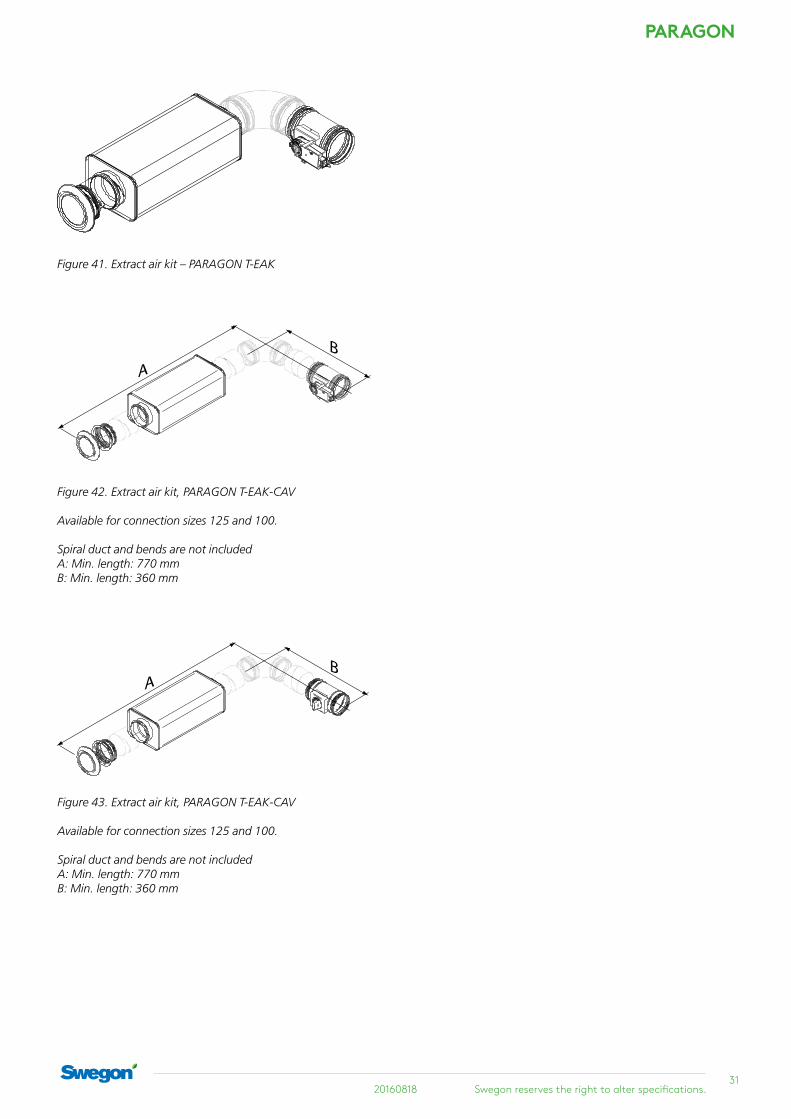
Figure 41. Extract air kit – PARAGON T-EAK
A
B
AB
Figure 42. Extract air kit, PARAGON T-EAK-CAV Available for connection sizes 125 and 100. Spiral duct and bends are not included A: Min. length: 770 mm B: Min. length: 360 mm
Figure 43. Extract air kit, PARAGON T-EAK-CAV Available for connection sizes 125 and 100. Spiral duct and bends are not included A: Min. length: 770 mm B: Min. length: 360 mm
PARAGON
32Swegon reserves the right to alter specifications. 20160818
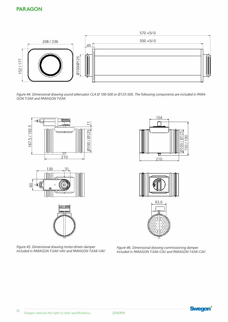
Figure 44. Dimensional drawing sound attenuator CLA Ø 100-500 or Ø125-500. The following components are included in PARA-GON T-SAK and PARAGON T-EAK:
Figure 45. Dimensional drawing motor-driven damper. Included in PARAGON T-SAK-VAV and PARAGON T-EAK-VAV
Figure 46. Dimensional drawing commissioning damper. Included in PARAGON T-SAK-CAV and PARAGON T-EAK-CAV
45

3320160818 Swegon reserves the right to alter specifications.
PARAGON
Ordering key
Specification, PARAGONType PARAGON comfort module for cooling, heating, ventilation and control. As standard, factory fitted compo-nents are included for plug & play installation.
PARAGON delivery demarcationSwegon’s limits of supply are at the connection points for water.
At these connection points, the RE pipework contractor connects to plain pipe end and/or male threads towards valves, fills the system, bleeds it and tests the pressure in the circuits.
The ventilation contractor connects to the duct connec-tions with dimensions as specified on the basic size draw-ing in the section "Dimensions".
EE electrical equipment contractor provides a 24 V AC network power supply or earthed 230 V outlets for a transformer, as well as a junction box, if required, installed in a wall for a room thermostat.
The building contractor cuts the openings in corridor wall for the supply air duct, in the interior wall and suspended ceiling for the supply air and extract air grilles and in the bathroom ceiling for the extract air duct.
The electrical contractor connects the power (24V) and signal cables to the connection terminals with spring-loaded snap-in connections.
Maximum cable cross section 2.5 mm2. For safe opera-tion, we recommend cable ends with ferrules.
PARAGON c aaaa- b- ccccc- d- 125 ef
Version:
Length (mm) 775, 900, 1100. 1300 and 1500
Function:
A = Cooling
B = Cooling and heating
Capacity variant NC - Normal design HC - High capacity design HC CCO - High capacity design with CCO valve
Connection side R - Right L - Left
Duct connection Ø 125
Flow variant Upper nozzle row: L, M, H Lower nozzle row: L, M, H
The PARAGON ordering key

PARAGON
34Swegon reserves the right to alter specifications. 20160818
Supply air kit VAV: PARAGON CRTc motor-driven damper with tight damper blade with damper actuator and CLA sound attenuator
CAV: PARAGON CRPc manually adjustable damper with perforated damper blade and CLA sound attenuator
Extract air kit VAV: PARAGON CRTc motor-driven damper with tight damper blade with damper actuator, CLA sound attenuator and extract air register with mounting frame
CAV: PARAGON CRPc manually adjustable damper with perforated damper blade, CLA sound attenuator and extract air register with mount-ing frame
Flexible connec-tion hose
Connection hose supplied with clamping ring coupling, push-on coupling or union nut.
Assembly piece Ceiling mounting bracket and threaded rod for mounting in ceiling. Double threaded rods with thread lock are also available.
Venting nipple Venting nipple with push-on cou-pling for connection to the return pipe for water, diameter: 12 mm
Grille lock Grille lock for fixing the position of the supply air grille.
Spigot Spigot for the supply air grille
Spigot for the return air grille
For further accessories for the control equipment, see the CONDUCTOR and LUNA product data sheets and the CCO valve data sheet.
Available to order, kit and accessories Ordering Key, Accessory kitSupply air kit PARAGON c T-SAK-VAV- aaa
Version:
Kit with motor-driven damper
Ø100; Ø125
Supply air kit PARAGON c T-SAK-CAV- aaa
Version:
Kit with manually adjustable damper
Ø100; Ø125
Extract air kit PARAGON c T-EAK-VAV- aaa
Version:
Kit with motor-driven damper
Ø100; Ø125
Extract air kit PARAGON c T-EAK-CAV- aaa
Version:
Kit with manually adjustable damper
Ø100; Ø125
3520160818 Swegon reserves the right to alter specifications.
PARAGON
Ordering Key, Accessories
Assembly piece SYST MS M8 aaaa- b
Length threaded rod (mm): 200; 500; 1000
Type: 1=One threaded rod 2=Two threaded rods and one thread lock
Supply air grille incl. 50-90 mm spigot
PARAGON c T- SG- aaaa
L = 775, 900, 1100, 1300, 1500
Spigot for the supply air grille 50-90 mm
PARAGON c T- OE-SG aaaa
L = 775, 900, 1100, 1300, 1500
Return air grille incl. 40-65 mm spigot
PARAGON c T- RG- aaaa
L = 775, 900, 1100, 1300, 1500
Spigot for the return air grille 40-65 mm
PARAGON c T- OE-RG aaaa
L = 775, 900, 1100, 1300, 1500
Flexible connection hose, (x1) SYST FH F1- aaa- 12
Clamping ring coupling (Ø12 mm) against pipe at both ends (excl. support sleeves)
Length (mm): 300; 500; 700
Flexible connection hose, (x1) SYST FH F20- aaa- 12
Quick-fit coupling push-on (Ø12 mm) against pipe at both ends
Length (mm): 275; 475; 675
Flexible connection hose, (x1) SYST FH F30- aaa- 12
Quick-fit coupling push-on, (Ø12 mm) against pipe at one end, union nut G20ID at the other end.
Length (mm): 200; 400; 600
Venting nipple SYST AR12
Grille lock PARAGON T-GL
Condensation sensor, aaaa
wired to terminal, (x1)
WCD2 proactive condensation control CG-IV reactive condensation control
Specification textExample of a specification text according to VVS AMA.
PCT.312 Duct connected chilled beams.
KB XX
Swegon’s PARAGON comfort module that supplies air via a supply air grille in a wall and has integrated circulating air opening in the bottom part.
For rear edge installation in a wall/ceiling, with the follow-ing functions:
• Cooling• Heating, water • Ventilation• VariFlow for simple adjustment of the airflows• ADC • Ø125 mm duct connection• Integrated circulating air opening in face plate• Coil and control equipment, if required, accessible via
the rear of the product or via the recirculating air grille• Cleanable• Fixed measurement tapping with hose• Contractor demarcation at connection point for water
and air as in outline drawing.• At the points of connection the pipe contractor con-
nects to 12 mm plain pipe end after which the ventila-tion contractor connects the Ø125 mm insertion piece (sleeve).
• The pipe contractor fills, bleeds, tests the pressure and assumes responsibility for the design water flows reaching each branch of the system and the unit.
• The ventilation contractor conducts initial commission-ing of the airflows
• Eurovent certified• Grilles in standard colour RAL 9003
Accessory kits:• PARAGON c-T-SAK-VAV-aaa xx pcs.• PARAGON c-T-SAK-CAV-aaa xx pcs.• PARAGON c-T-EAK-VAV-aaa xx pcs.• PARAGON c-T-EAK-CAV-aaa xx pcs.
Accessories:• Supply air grille, PARAGON c T-SG-aaa xx pcs.• Spigot (supply air) PARAGON c T-OE-SG-aaaa xx pcs.• Grille lock, PARAGON T-GL xx pcs.• Return air grille, PARAGON c T-RG-aaaa xx pcs. • Spigot (return air) PARAGON c T-OE-RG-aaaa xx pcs.• Commissioning damper SYST CRPc 9-125, xx pcs.• Assembly piece, SYST MS M8 aaaa-b• Flexible connection hose, SYST FH F1 aaa- 12 xx pcs.• Flexible connection hose, SYST FH F20 aaa- 12 xx pcs.• Flexible connection hose, SYST FH F30 aaa- 12 xx pcs.• Venting nipple, SYST AR 12 xx pcs.etc.
Specify the quantities individually or with reference to the drawing.