paragon 2000 plus manual turbo owner's book fires paragon 2000 plus manual turbo owner's...
TRANSCRIPT

PARAGON FIRES
PARAGON 2000 Plus MANUAL TURBO
Owner's Book
NATURAL GAS & PROPANE GAS MODELS SURFACE MOUNTED POWER FLUE UNIT
Or
SUNK IN THE WALL POWER FLUE UNIT
INCLUDES USER, INSTALLATION & MAINTENANCE
INSTRUCTIONS
Please read these instructions carefully before you start using the
appliance
Keep this booklet handy for future reference
This appliance is
for use in GREAT BRITAIN or IRELAND only

LT5052 (iss 05 03:11)) 2
PARAGON 2000 Plus MANUAL TURBO User’s Instructions
CONTENTS PAGE
User’s Instructions SECTION ONE Consumer Protection Information 4 Introduction Health & Safety Notice 4 Important Information 5 SECTION TWO Electrical Connection 6 Operation Operating The Fan 6 Lighting The Fire 6 SECTION THREE Trim, fret, or Fascia 7 Cleaning Black Painted Surfaces 7 Pilot Assembly 7 Fan Outlet 8 SECTION FOUR Warnings 8 Fuel BED Cleaning and Layout Coal Layout 9 Pebble Layout 12 SECTION FIVE Replacement Parts 14

LT5052 (iss 05 03:11)) 3
PARAGON 2000 Plus MANUAL TURBO User’s Instructions
CONTENTS Installation Instructions SECTION SIX Appliance Data 14 SECTION SEVEN Regulations and Warnings 16 SECTION EIGHT Flue Terminal Position 16 Siting the Appliance Surround 17
Hole in the Wall Installation 18 Shelf & Side Clearances 19
SECTION NINE Installing The Fire Box 19 To install the Appliance Installation Options 20
1 Inset Fan – Fire Sited In Cavity 21 2 Surface Mounted Fan – Fire Sited In Cavity 22 3 Inset Fan – Fire Sited in surround or False Chimney Breast 23 4 Surface Mounted Fan – Fire Sited in surround or False Chimney Breast 24
Connecting to the Electrical Fitting 25 Connecting the Gas Supply 25
Installing into Timber Frame 26
SECTION TEN Check Burner Pressure and General Operation 29 Checking Operation of Fire Checking Product Clearance 29
Fan Failure Test 29 Blocked Flue Test 29 Final Assembly 29 Advise the Customer 30
SECTION ELEVEN General 30 Maintenance Instructions Pilot Linting 30
Replacement of Gas Control 31 Replacement of Injector 31 Replacement of Oxy-Pilot Assembly 31
Replacement of Silencer 31 Replacement of Fan Control Unit 32
Replacement of Fan Housing 32 Replacement of Fan Assembly 32
Replacement of Pressure (Flow) Switch 32 SECTION TWELVE Wiring Diagram 33 SECTION THIRTEEN Mains Check 33 Fault Finding Instructions Pressure Switch Check 34 Fan Check 34 Earth Check 34 Fault Finding Chart 35
LT5052 (iss 05 03:11)) 4
PARAGON 2000 Plus MANUAL TURBO User’s Instructions
SECTION ONE Introduction
Consumer Protection Information As manufacturers and suppliers of heating products, we take every care, as far as is reasonably practicable, that these products are so designed and constructed as to meet the general safety requirement when properly used and installed. To this end, our products are thoroughly tested and examined before despatch.
IMPORTANT NOTICE: Any alteration that is not approved by the appliance manufacturer could invalidate the approval of the appliance, operation of the warranty and could affect your statutory rights.
Health and Safety Notice Important This appliance could contain some of the materials, indicated below, that could be interpreted as being injurious to health and safety. It is the users / installers responsibility to ensure that the necessary personal protective clothing is worn when handling these materials, see below for information.
Artificial Fuels, Mineral Wool, Insulation Material, Refractory/Ceramic Fibres, Glass Yarn - may be harmful if inhaled, may be irritating to skin, eyes, nose and throat. When handling avoid inhaling and contact with skin or eyes. Use disposable gloves, facemasks and eye protection. After handling wash hands and other exposed parts. If a vacuum is used for cleaning the coals or cleaning after servicing / installation it is recommended that it be of the type fitted with a HEPA filter. Disposal of refractory/ceramic materials. To keep dust to a minimum these materials should be securely wrapped in polythene and be clearly labelled ‘RCF waste’. These materials are not classified as ‘hazardous waste and should be disposed of at a site licensed for the disposal of industrial waste.
The PARAGON 2000 Plus MANUAL TURBO is designed and tested to the requirements of the European Standard EN 509.
The PARAGON 2000 Plus MANUAL TURBO is intended for decorative purposes.
The PARAGON 2000 Plus MANUAL TURBO is designed for use in locations, which do not have a conventional chimney. This is achieved by extracting the products of combustion of the fire using a centrifugal fan via a ducting system connected through an outside wall. Located behind the fret are the fan control unit, with on and off switches, and the gas control.
The PARAGON 2000 Plus MANUAL TURBO incorporates features, which prevent the appliance being used should the flue become blocked, or the fan fails. The effective operation of the flue is monitored by a device which, when operated, supplies gas to the burner. If a low flow condition occurs whilst the fire is in operation the fan will automatically switch to the high-speed mode to try and clear the restriction. If the restriction is cleared, the fan will return to the normal running mode or, if not the gas to the burner system will be shut off.
The PARAGON 2000 Plus MANUAL TURBO incorporates a safety device in the form of an Oxygen Depletion System, which constantly monitors the oxygen in the room and will cause the fire to switch off if the oxygen level reduces, this may be due to insufficient ventilation or a blocked or restricted flue. If this regularly occurs do not attempt to relight the appliance until a qualified engineer has checked it, the problem may not be due to lack of air or a defective flue. THIS DEVICE MUST NOT BE OVERRIDDEN.
When the appliance is not in use the gas control and the fan should be switched off.
Operating the fan without the gas being switched on can reduce excessive drafts from the flue when the fire is not in use.

LT5052 (iss 05 03:11)) 5
PARAGON 2000 Plus MANUAL TURBO User’s Instructions
SECTION ONE Introduction
IMPORTANT INFORMATION
The PARAGON 2000 MANUAL TURBO is available in two versions Natural Gas or LPG (Propane Gas Only). The markings (G20 for natural gas or G31 for propane) on the packaging and the data badge specify the gas for which the appliance has been factory set. NOTE: This appliance should only be used on the appropriate gas specified. It is not suitable for conversion from one gas to the other.
The cast fire front (fret) or approved fascia must be positioned in front of the fire whilst it is burning and must conform to the following: It must be made from non-combustible material. Its general construction should enable it to stand firmly across the full width of the burner. The design of the fire front (fret) must have a removable ashtray cover (lower section). The ash tray cover must have cut-outs and or holes which provide ventilation to the underside of the burner. The effective area of ventilation through the ash tray cover must be greater than 1365mm2 (2.12 sq. ins.)
Failure to install the appliance correctly could lead to prosecution. In GB (Great Britain), the appliance must be installed by a competent person i.e. CORGI-registered, in accordance with the GAS SAFETY (INSTALLATION AND USE) REGULATIONS, The Building Regulations (or The Building Regulations (Scotland) or The Building Regulations (Northern Ireland)) and The Current I.E.E. Wiring Regulations, if appropriate. In IE (Ireland), the appliance must be installed by a competent person and installed in accordance with the current edition of I.S.813 Domestic Gas Installation, the current Building Regulations and the current ETCI rules for electrical installation, if appropriate.
This appliance has a naked flame, as with all such fires it is recommended that a fireguard should be used for the protection of children, the elderly, and infirm. Fireguards should conform to BS 6539 (1984) (Fireguards for use with solid fuel appliances).
During initial firing an odour may be evident. This is the starch binder used during the manufacture of the fibre components of the fire, and there are no harmful effects produced.
During the normal operation of the fire some black staining may appear on some parts of the fuel bed. This is quite normal and adds to the appearance of the appliance. However, if excessive black staining does occur it may be due to the fuel bed being incorrectly laid. This should be checked prior to contacting a service engineer.
Like all appliances incorporating an aerated burner with a fanned flue system a low frequency noise may be heard.
It is advised that the PARAGON 2000 Plus MANUAL TURBO fanned flued fire is serviced annually as it is more likely to provide trouble-free operation.
The flue should be regularly checked and kept clear of any obstruction. Refer to Section 3 “Cleaning Fan Outlet.”
In GB (Great Britain) the fire does not normally require purpose built ventilation, but if it as been necessary to provide ventilation it should be checked periodically to ensure that it is free from any obstructions.
In IE (Ireland) permanent ventilation must comply with the current edition of IS813.
Rubbish must not be thrown onto the fuel bed under any circumstances.

LT5052 (iss 05 03:11)) 6
PARAGON 2000 Plus MANUAL TURBO User’s Instructions
SECTION TWO Operation ELECTRICAL CONNECTION (WARNING: THIS APPLIANCE MUST BE EARTHED) This appliance is suitable for use on 220 - 240V 50Hz mains supply only. The wiring in the mains lead on this appliance is colour coded as follows:-
Green & Yellow - Earth Blue - Neutral Brown - Live
The mains plug terminal should be connected as shown and a 3A fuse must be used to protect the appliance.
The appliance control knob and fan switches are located behind the fret on the left hand side. The full lighting procedure is as follows: -
OPERATING THE FAN a. Ensure that the electricity supply is connected and switched on. b. Lift off the ash pan cover and press the switch marked on. The red light at the base of the
control unit will illuminate and the fan should operate at the high speed. After a short period (up to 20 seconds) the light will extinguish, the fan speed will reduce and the fire can be lit (see Lighting the Fire).
c. If the red light does not illuminate on initial operation, or the fan does not run press the switch marked OFF to reset the control and wait approximately 1 min. before repeating steps 'a' and 'b' above.
d. During normal use the red light may illuminate indicating a flue restriction (this may be due to a flue obstruction or adverse wind conditions). In these circumstances the fan speed will increase and if the condition is not corrected in approximately 10 seconds the gas supply will be shut off. The control knob must be turned to the position and the off switch must be pressed to reset the control. Before attempting to relight the fire wait 3 minutes. If this occurs refer to Section 3 “Cleaning Fan Outlet.”
LIGHTING THE FIRE a. Push the control knob in as far as possible on gas control.
b. Turn knob anti-clockwise until a click is heard. The knob will stop at the position marked and a spark should be seen at the tip of the ignition probe. At the same time the pilot flame should light. KEEP THE KNOB PRESSED IN FOR 20 SECONDS. Should the pilot fail to light, turn the control knob clockwise to the position, wait 3 minutes, and repeat the procedure.
b. After lighting the pilot flame the control knob should be allowed to spring out slightly. This will
allow you to turn the knob further anti-clockwise to the position marked . The pilot flame should then ignite the main fire.
d. It is possible to adjust the height of the flames by turning the control knob between the
positions marked and . Note that the knob 'latches' in position at either end of this movement and must be pushed in slightly before it can be turned.

LT5052 (iss 05 03:11)) 7
PARAGON 2000 Plus MANUAL TURBO User’s Instructions
SECTION Two Operation Continued NOTE: During normal use the red light may illuminate indicating a flue restriction (this may be due to a flue obstruction or adverse wind conditions). In these circumstances the fan speed will increase and if the condition is not corrected in approximately 10 seconds the gas supply will be shut off. The control knob must be turned to the position and the off switch must be pressed to reset the control. Before attempting to relight the fire wait 3 minutes.
TURNING OFF THE FIRE a. Depress the knob slightly and turn fully clockwise to the position. b. Turn the fan off by pressing the switch marked 'OFF'. The fan should always be turned off
when the fire is not in use.
SECTION THREE Cleaning Warning: - Before you clean any part of the appliance ensures that the appliance is turned off and cold.
CLEANING: TRIM, FRET or FASCIA Abrasive or chemical cleaner should never be used. The fret and trim may be cleaned with a clean damp cloth. N.B The trim and fire fret should be removed for cleaning. (The trim is held in place by magnetic strips).
CLEANING: BLACK PAINTED SURFACES
These surfaces should be dusted regularly and any marks removed with a soft cloth.
Abrasive or chemical cleaner should never be used.
CLEANING: PILOT ASSEMBLY In some instances you may experience ignition problems even when the appliance is new. This may be due to the aeration hole in the pilot body being partial blocked with dust, pet hairs or other foreign matter. The source of this debris could be such things as carpet fibres, decorating or pet etc. To clean the pilot, remove the fire front and ashpan. The pilot is located on the right hand side of the appliance, any debris in or around the aeration hole should be remove using the nozzle of a vacuum cleaner. It is advisable not to blow the debris into the hole as this may cause more of a restriction and not rectify the problem.

LT5052 (iss 05 03:11)) 8
PARAGON 2000 Plus MANUAL TURBO User’s Instructions
SECTION THREE Cleaning Continued
CLEANING: FAN OUTLET Warning: - Before cleaning the fan outlet ensure that the appliance is turned off and cold. In addition isolate the appliance from the electrical supply (i.e. unplug or switch off at the socket).
If the red light adjacent to the on/off switches does not extinguish or cycles on and off, it may be that the fan outlet has become obstructed (e.g. by plants or other objects) or the pipe which senses that the fan is operating correctly has become restricted (e.g. spider, insects or other debris), particularly if the appliance has not been used for some time. If appropriate, remove the obstructions from the fan outlet and, with the aid of a pipe cleaner or similar object, clean the pipe located in the centre of the outlet grille. This should be checked prior to contacting a service engineer.
SECTION FOUR Fuel Bed Cleaning And Layout Warning: -
Before you clean any part of the appliance ensures that the appliance is turned off and cold.
Use only the fuel bed components provided, no additional parts must be added.
Incorrect positioning of the fuel bed components could result in the excessive black on some parts of the fuel bed.
Important: - Refer to the ‘Health & Safety Notice located on page 4 of this booklet before cleaning or replacing any refractory material.
The fuel bed components are delicate and they should be handled with great care.
The loose parts and moulded shapes may be removed for cleaning. They can be brushed very gently with a soft brush to remove dust or any deposits.
A vacuum cleaner may only be used after the loose components and moulded shapes have been removed.
CARE SHOULD BE TAKEN TO AVOID CONTACT WITH THE REFRACTORY LININGS THEIR SURFACES ARE DELICATE AND SHOULD NOT BE WIPED OR RUBBED.
It is important that all the fuel bed moulded shapes are positioned as shown in these instructions.
Clean pipe with the aid of a pipe cleaner or similar object.
Ensure fan outlet is clear and free from any obstructions.

LT5052 (iss 05 03:11)) 9
PARAGON 2000 Plus MANUAL TURBO User’s Instructions
SECTION FOUR Fuel Bed Cleaning And Layout Continued
FUEL BED LAYOUT (COAL OPTION) Ensure the BASE MATRIX is in position as
shown. It should be located against the rear edge of the burner outlet.
Locate the LEFT HAND and RIGHT HAND FRONT COALS as shown so that they sit in front of the burner, positioned behind the front lip of the tray. Ensure that they lean back against the BASE MATRIX. Note: It is very important that they are located in their correct positions. They are marked on the rear ‘L’ for LEFT HAND FRONT COAL and ‘R’ for RIGHT HAND FRONT COAL.
Separate the coal into the two size groups
The loose coals provided consist of 5 COALS ‘A’ SHAPE and 9 COALS ‘B’ SHAPE.
.

LT5052 (iss 05 03:11)) 10
PARAGON 2000 Plus MANUAL TURBO User’s Instructions
SECTION FOUR Fuel Bed Cleaning And Layout Continued
Lay the first row of loose coals “B” and “A” shapes as shown.
Lay a second row of loose coals “B” and “A” shapes as shown.

LT5052 (iss 05 03:11)) 11
PARAGON 2000 Plus MANUAL TURBO User’s Instructions
SECTION FOUR Fuel Bed Cleaning And Layout Continued
Finally, lay the last three loose coals 2 “B” shapes and 1 “A” shape

LT5052 (iss 05 03:11)) 12
PARAGON 2000 Plus MANUAL TURBO User’s Instructions
SECTION FOUR Fuel Bed Cleaning And Layout Continued PEBBLE LAYOUT
FUEL BED COMPONENTS
Base Matrix
L & R Front Pebbles
Number Pebbles:-
Pebble identification QTY
Heart shape 1
Oblong shape 4
Large shape 3
Medium shape 2
Small shape 2
Total 12
PEBBLE LAYOUT
WARNING Take great care when positioning the pebbles to avoid marking the black linings.
Ensure the BASE MATRIX is in position as shown located against the rear edge of the burner outlet.
Locate the LEFT HAND and RIGHT HAND FRONT PEBBLES as shown so that they sit on the front rail and lean back against the BASE MATRIX. Note it is most important that they are located in their correct positions. They are marked on the rear "L" for LEFT HAND FRONT PEBBLE and "R" for RIGHT HAND FRONT PEBBLE.

LT5052 (iss 05 03:11)) 13
PARAGON 2000 Plus MANUAL TURBO User’s Instructions
SECTION FOUR Fuel Bed Cleaning And Layout Continued
Lay one row of pebbles at the front of the fire as shown.
Lay another row of loose pebbles shown.
Lay another row of loose pebbles as shown.

LT5052 (iss 05 03:11)) 14
PARAGON 2000 Plus MANUAL TURBO User’s Instructions
SECTION FIVE Replacement Parts
The only user removable parts are: -
The loose pebbles or coals.
The left hand front pebble or coal shape
The right hand front pebble or coal shape.
The base matrix
Cast Fret
Decorative Trim
SECTION SIX Appliance Specification Data Label Location, Natural Gas & LPG: Top behind decorative trim. Gas Connection, Natural Gas & LPG: 8 mm OD Tube. Length of Flue 1 metre (max). Length of Flue Pipe (Supplied) 435mm, 1 metre length available as an optional extra. NATURAL GAS VERSION Category of Appliance: BAS Category I2H Gas type: G20 Gas Pressure: 20 mbar Gas input high: 7.00kW Gross Gas input low: 2.40kW Gross Injector Main: Size 460 Oxy-pilot NG9040
PROPANE GAS VERSION Category of Appliance: BAS Category I3P Gas type: G31 Gas Pressure: 37 mbar Gas input high: 7.00 kW Gross Gas input low: 2.40 kW Gross Injector Main Size 135 Oxy-pilot LPG9222 NOTE: The efficiency of this appliance has been measured as specified in EN13278-2003 and the result is 62.0%. The gross calorific value of the fuel has been used for this efficiency calculation. GasTec have certified the test data from which it has been calculated. The efficiency value may be used in the UK Government’s Standard Assessment Procedure (SAP) for energy rating of dwellings.

LT5052 (iss 05 03:11)) 15
PARAGON 2000 Plus MANUAL TURBO Installation
Instructions
SECTION SEVEN Regulations and Warnings
This appliance must only be installed in GB or Ireland.
It is available in two versions Natural Gas or LPG (propane gas only). The markings (G20 for natural gas or G31 for propane) on the packaging and the data badge specify the gas for which the appliance has been factory set. This appliance should only be used on the appropriate gas specified. It is not suitable for conversion from one gas to the other. Prior to the installation ensure that the local distribution conditions (identification of type of gas and pressure) and adjustment of the appliance are compatible. (G20 @ 20mbar).
The appliance is intended for decorative purposes.
GB. (GREAT BRITIAN) This fire does not normally require purpose build ventilation, providing normal adventitious room ventilation exists. The installer must satisfy this point by carrying out the mandatory spillage test.
IE (Ireland) Permanent ventilation must comply with the current edition of IS813.
GB, (Great Britain) It is the law that all gas appliances must be installed by a competent person; i.e. a Corgi registered installer, in accordance with the current gas safety (installation and use) regulations (as amended), all relevant parts of the local and national building regulations and all relevant recommendations of the following British Standards. Failure to do so could lead to prosecution
The following are the relevant Codes of Practice and British Standards: - BS 5871 BS 8303 BS 5440 part 1 BS 1251 BS 6891 BS 6461 parts 1 & 2 BS 715 BS 1289 part 1 Note: - This appliance must be installed to current versions of the above standards and include any relevant amendments.
The Building Regulations issued by the Department of the Environment. The Building Standards (Scotland) (Consolidation) Regulations issued by the Scottish Development Office. All external wiring between the appliance and the electrical supply must comply with current I.E.E. Regulations.
IN IE, (Ireland) THE APPLIANCE MUST BE INSTALLED BY A COMPETENT PERSON AND INSTALLED IN ACCORDANCE WITH THE CURRENT EDITION OF I.S.813 DOMESTIC GAS INSTALLATION, THE CURRENT BUILDING REGULATIONS, AND THE CURRENT ETCI RULES FOR ELECTRICAL INSTALLATION, IF APPROPRIATE.
WARNING
This PARAGON 2000 Plus MANUAL TURBO requires an electricity supply (220-240V ~ 50Hz) and must be protected by a 3A fuse. All external wiring between the appliance and the electrical supply must comply with the current I.E.E. regulation.
A means of electrical isolation should be readily accessible to the user.
The appliance must be installed on a suitable outside wall.
Where the appliance is fitted at floor level a non-combustible hearth must be provided to
comply with the building regulations or a suitable proprietary fire surround with a 100 o
C rating.

LT5052 (iss 05 03:11)) 16
Fig 1
PARAGON 2000 Plus MANUAL TURBO Installation
Instructions
SECTION SEVEN Regulations and Warnings Continued A fire fret must be used with this appliance and see Section One.
The appliance incorporates a safety device in the form of an Oxygen Depletion System which constantly monitors the oxygen in the room and will cause the fire to switch off if the oxygen level reduces, for instance due to insufficient ventilation or a blocked flue. THIS DEVICE MUST NOT BE OVERRIDDEN.
This appliance has a naked flame, as with all such fires it is recommended that a fireguard should be used for the protection of children, the elderly and infirm. Fireguards should conform to BS 6539 (1984) (Fireguards for use with solid fuel appliances).
SECTION EIGHT Siting the Appliance
FLUE TERMINAL POSITION The flue outlet must terminate on an outside wall. The minimum flue terminal clearances, which must be maintained, are shown in fig.1: -
A Directly below an operable window or other opening, eg. air brick 300mm B Below gutters, soil pipes or drain pipes 75mm C Below eaves 200mm D Below balconies or car port roof 200mm E From vertical drain pipes and soil pipes 75mm F From internal and external corners 150mm G Above ground, roof or balcony level 150mm H From a surface facing a terminal 600mm I From a terminal facing a terminal 1200mm J From an opening in the car port into the dwelling, e.g. door, window, etc. 1200mm K Vertically from a terminal on the same wall 1500mm L Horizontally from a terminal on the same wall 300mm

LT5052 (iss 05 03:11)) 17
500mm
390-420mm
560mm 605mm
700mm (min.)
300mm (min.) Forward of the surround back panel.
50mm (min.)
CUTOUT IN SURROUND
FASCIA
Fig 2
PARAGON 2000 Plus MANUAL TURBO Installation Instructions
SECTION EIGHT Siting the Appliance Continued
SURROUND
A non-combustible hearth must be provided beneath the appliance. The hearth must be symmetrically disposed about the fire position with a minimum thickness of 12 mm and the perimeter 50mm above floor level. The width must extend a minimum of 150 mm either side of the fireplace opening and a depth of 310 mm from the vertical fixing plane (300 mm from the front of the fuel bed). Any combustible material above the opening must be removed up to a height of 590 mm above hearth level. Purpose-built superimposed fire-resistant hearths and back panels, specified as suitable by the
manufacturers, or a suitable proprietary fire surround with a 100o
C rating may be used. IMPORTANT: Care should be taken to prevent any damage being caused to surrounding soft furnishings or decoration, e.g. many embossed vinyl wall coverings may become discoloured if placed too close to the appliance. If the appliance is to be installed in a room with anything other than conventional cavity wall construction, then provision must be made (e.g. special surround, false chimney breast) to accommodate the firebox. A minimum depth of 170 mm (or 143 mm when optional spacer fitted) is required with an opening in the fireplace fascia of 390 mm X 560mm. The flue length must be between 100mm (min) and 1m (max).

LT5052 (iss 05 03:11)) 18
PARAGON 2000 Plus MANUAL TURBO Installation Instructions
SECTION EIGHT Siting the Appliance Continued
Hole in the Wall Installation Please read these instructions carefully if you intend an Installation without a hearth.
This appliance must be installed in accordance with all relevant sections of approved document “J” of the building regulations
It is recommended that a non combustible hearth extends a minimum of 300mm forward of the fire opening and a minimum of 150mm either side, and that a rise exist at the front edge and sides of the hearth of a minimum of 50mm.
The fire may be installed so that its base sits on a surface of a fire opening at least 105 mm up from the floor (this is to ensure that no flame or incandescent material is less than 225mm above the floor, a requirement of approved document “J”). Where this is the case a means must be provided to support the fret this may typically be meet with a small projecting hearth of minimum 100mm.Unless the fret is fixed to the appliance or is an integral part of the fascia of the appliance.
Consideration should be given to the location of the appliance ensuring it is very visible and it should be positioned at a height were it can clearly be seen on approach.
Frets, and Fascias used for HOLE in the WALL must be compliant with Paragon Fires CE approval; these are listed at the end of this page.
Where the fire is fitted as a “Hole in the Wall” without a hearth the installer MUST ensure the appliance is fixed firmly into the opening to ensure no movement takes place to the fuel bed when the appliance controls are operated.
The installer MUST ensure that the fuel bed is laid correctly and securely
The installer MUST advise the user that care should be taken when the appliance is in use to ensure occupants do not get unnecessarily close to the appliance or position furniture or other appliances to close.
The installer MUST remind user of the requirement to fit a “secure fireguard” where the room is used by elderly, infirm or young persons.
The installer MUST explain to the user that the area immediately in front of the appliance must always be keep clear of combustible items other than the floor covering (which must be fixed)
In the case of the Pebble fuel bed an alternative layout for “Hole in the Wall” must be followed refer to Section 4 Pebble Layout in this Manual, this alternative layout MUST adhered to for ALL HOLE in the WALL installations.
List of approved Paragon Frets
List of Approved Fascias
Wellington 2000
Odyssey 2001
Gate
Solar
Post

LT5052 (iss 05 03:11)) 19
50 100 150 200 250 300 3500
700
750
800
850
900
950
1000
EXAMPLE: 900 SHELF HEIGHT= 250 MAX. SHELF WIDTH
"B" SHELF WIDTH
"A"S
HE
LF
HE
IGH
T F
RO
M H
EA
RT
H
All dimensions in mm
650
Fig 3
PARAGON 2000 Plus MANUAL TURBO Installation Instructions
SECTION EIGHT Siting the Appliance Continued CLEARANCE TO SHELF Minimum clearance from hearth to underside of combustible shelf should be 650mm provided shelf depth 125mm or less. When the shelf depth is increased by increments of 12.5 mm greater than 125mm, add 25mm to the 650mm minimum clearance. CLEARANCE TO SIDES OF FIRE Minimum width between vertical sides of combustible surround should not be less than 700 mm provided fire is central to surround and sides do not project more than 150 mm. When vertical side forward projection is increased by 12.5 mm add 50 mm to inside width of surround. NOTE: When fire is fitted this provides a minimum side clearance of 100mm.
SECTION NINE To Install the Appliance INSTALLING THE FIRE BOX Check that the proposed site conforms to the specifications as previously stated. Cut opening into cavity (fig. 3) and lay down the hearth of non-combustible material centrally about the proposed centre line of the appliance taking care to protect the hearth surface against scratching. NOTE: If necessary a lintel should be fitted to support the brickwork. The opening in the cavity around the appliance should be suitably sealed to prevent ingress of gases using a non-porous material (i.e. rockwool). Use the length of foam to seal around the flange of the fire and the back panel. The floor of the recess should then be screeded to the hearth level to allow for accurate positioning of the firebox and flue spigot.
LT5052 (iss 05 03:11)) 20
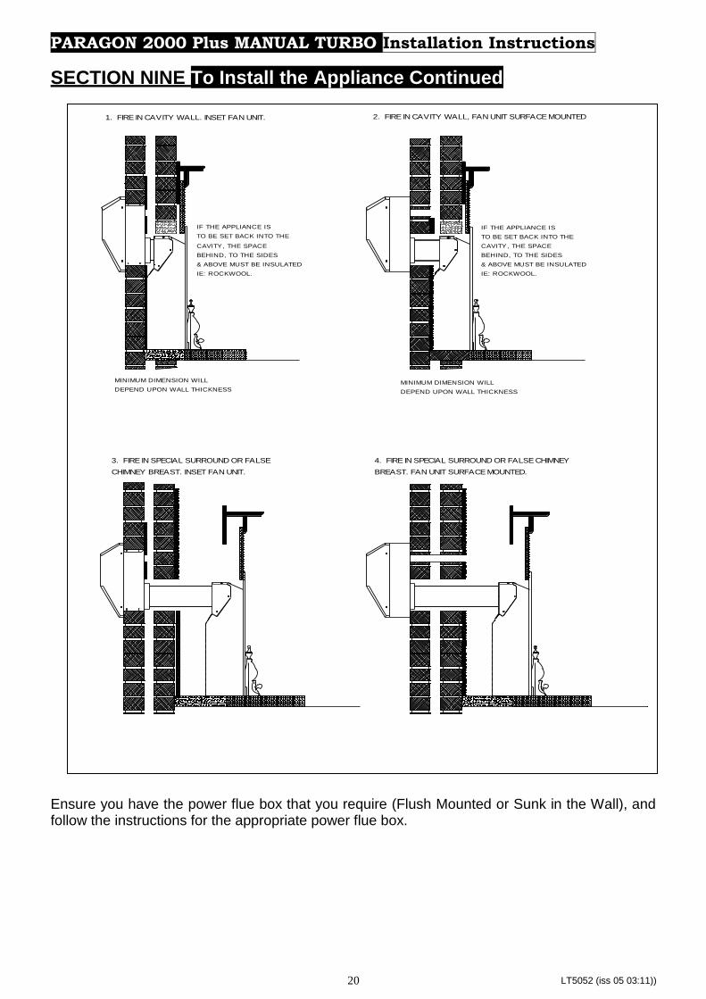
IF THE APPLIANCE IS
TO BE SET BACK INTO THE
CAVITY, THE SPACE
BEHIND, TO THE SIDES
& ABOVE MUST BE INSULATED
IE: ROCKWOOL.
MINIMUM DIMENSION WILL
DEPEND UPON WALL THICKNESS
INSTRUCTIONS\ARTWORK\PARAGON 2000 TURBO\2000 TURBO SIDE VIEW
IF THE APPLIANCE IS
TO BE SET BACK INTO THE
CAVITY, THE SPACE
BEHIND, TO THE SIDES
& ABOVE MUST BE INSULATED
IE: ROCKWOOL.
MINIMUM DIMENSION WILL
DEPEND UPON WALL THICKNESS
1. FIRE IN CAVITY WALL. INSET FAN UNIT. 2. FIRE IN CAVITY WALL, FAN UNIT SURFACE MOUNTED
3. FIRE IN SPECIAL SURROUND OR FALSE
CHIMNEY BREAST. INSET FAN UNIT.
4. FIRE IN SPECIAL SURROUND OR FALSE CHIMNEY
BREAST. FAN UNIT SURFACE MOUNTED.
PARAGON 2000 Plus MANUAL TURBO Installation Instructions
SECTION NINE To Install the Appliance Continued
Ensure you have the power flue box that you require (Flush Mounted or Sunk in the Wall), and follow the instructions for the appropriate power flue box.

LT5052 (iss 05 03:11)) 21
SURFACE MOUNT
WIRING HARNESS HOLE
35mm
FOR FAN UNIT SET ON AN EXTER IOR WALL.
THE WIRING HARNESS CAN BE ROUTED THROUGH A 35mm HOLE DRILLED AT THE POSITION SHOWN.
IT MUST BE PROTECTED BY A CONDUIT TO PREVENT IT COMING INTO CONTACT WITH THE FLUE OR FIRE BOX.
FOR FAN UNIT SET IN THE EXTERIOR WALL.
THE WIRING HARNESS CAN BE ROUTED ALONG SIDE THE FLUE IF REQURED BUT IT MUST BE
PROTECTED BY A CONDUIT TO PREVENT IT COMING INTO CONTACT WITH THE FLU E OR FIRE BOX.
NOTE: SOLID LINE DENOTES THE OUTER PROFILE
OF THE FAN UNIT AND ACTUAL FLUE POSITION.
TO FIT FAN UNIT ON THE SURFACE OF AN
EXTERIOR WALL FOLLOW PROFILE OF THE
THE DOTTED LINE. SECURE TO WALL
USING SUITABLE FIXINGS.
SURFACE MOUNT
SECURING HOLE
SURFACE MOUNT
SECURING HOLE
SURFACE MOUNT
SECURING HOLE
INSET
SECURING HOLE
INSET
SECURING HOLE
INSET
SECURING HOLE
SURFACE MOUNT
SECURING HOLE
INSET
SECURING HOLE
TO FIT THE FAN UNIT IN THE EXTERIOR
WALL FOLLOW PROFILE OF THE BROKEN
LINE. SECURE TO WALL USING SUITABLE
FIXINGS.
PARAGON 2000 TURBO
FAN UNIT TEMPLATE
THIS TEMPLATE IS TO BE POSITIONED
ON THE OUTSIDE WALL OVER A PILOT
HOLE DRILLED AS DESCRIBED IN THE
INSTRUCTIONS.
(PILOT HOLE POSITION - CENTRE LINE
OF FIRE, 483mm VERTICAL FROM HEARTH LEVEL.)
REFER TO INSTALLAT ION INST RUCTIONS B EFORE FIT TING.
PILOT HOLE TO
BE ALIGNED HERE
THIS WAY UP.
Fig 4
PARAGON 2000 Plus MANUAL TURBO Installation Instructions
SECTION NINE To Install the Appliance Continued
1 MOUNTING THE INSET FAN HOUSING – FIRE SITED IN CAVITY IMPORTANT: STUDY THE ENCLOSED FAN UNIT TEMPLATE CAREFULLY BEFORE INSTALLATION. THE FAN UNIT MUST BE FITTED WITH THE FAN OUTLET DIRECTED DOWNWARDS (FIG. 6).
If installing the appliance into a conventional cavity wall, mark opening as shown in fig. 2 & 3.
Drill a pilot hole through both inner and outer leaf at the required position.
Cut away the plaster and inner leaf of brickwork to this line, exposing the cavity and rear face of the outer wall.
Using the template provided (shown in fig. 4), position the light grey dot in the centre of the large circle over the pilot hole on the outside brickwork.
Mark the wall following the long broken line, using a grinder cut out the rectangular hole for the fan housing.
The housing will be secured to the wall at the positions shown by the black dots using suitable fixings later.
Secure the fire into the opening, gas supply pipe and electrical cable appropriately routed in accordance with current regulations (NOTE: fire isolated from electrical supply at this time).
Remove the front cover from the housing and place to one side.
Disconnect the tubes from the pressure switch, making note of which tube fits on which outlet, (‘+’ on pressure switch to upper venturi outlet, ‘-‘ on pressure switch to lower outlet on venturi). Refer to fig. 6.

LT5052 (iss 05 03:11)) 22
Fig 5
PARAGON 2000 Plus MANUAL TURBO Installation Instructions
SECTION NINE To Install the Appliance Continued
Feed the wiring harness from the fire through a length of conduit, then feed the conduit and harness through the small hole. Exposing approximately 100mm of the harness to feed in through the grommet at the rear of the fan housing. IMPORTANT: DO NOT allow the wiring harness to lie against the firebox or the flue. They should be suitably shielded against the heat.
Undo and slide away the fan and fan plate to expose the flueway.
The length of flue that is required is determined by measuring the distance between the back of the fire to the fan housing flue stops.
Fit the doughnut seal between the flue spigot on the back of the fire and flueway of the housing to ensure an airtight seal is made. Refer to fig. 5.
The housing can now be secured to the wall using suitable fixings.
Carefully slide the fan and fan plate back into its position and secure.
Reconnect the tubes from the pressure switch to the venturi on the fan, (‘+’ on pressure switch to upper venturi outlet, ‘-‘ on pressure switch to lower outlet on venturi). Refer to Fig 6. Ensure that the venturi is clean and clear of any debris or obstructions prior to use.
Connect the leads from the pressure switch and fan to their respective tabs on the wiring harness.
Ensure that both earth leads from the fan and wiring harness are secured to the earth mounting point on the housing. IMPORTANT: THE APPLIANCE MUST BE EARTHED.
Fit the front cover over the housing and secure.

LT5052 (iss 05 03:11)) 23
Fig 6
Fig 7
PARAGON 2000 Plus MANUAL TURBO Installation Instructions
SECTION NINE To Install the Appliance Continued
2 SURFACE MOUNTED FAN HOUSING – FIRE SITED IN CAVITY IMPORTANT: STUDY THE ENCLOSED FAN UNIT TEMPLATE CAREFULLY BEFORE INSTALLATION. THE FAN UNIT MUST BE FITTED WITH THE FAN OUTLET DIRECTED DOWNWARDS (FIG 6).
If installing the appliance into a conventional cavity wall, mark opening as shown in Fig. 2 & 3.
Drill a pilot hole through both inner and outer leaf at the required position.
Using the template provided, position the light grey dot in the centre of the large circle over the pilot hole on the outside brickwork.
Using a 127mm (5”) core drill, drill through the outer leaf at the pilot hole position, shown by the circular dotted line.
Using a suitably sized drill, also drill through the outer leaf at the wiring harness position, shown by the small circular dotted line.
Feed the wiring harness from the fire through a length of conduit, then feed the conduit and harness through the small hole. Exposing approximately 100mm of the harness to feed in through the grommet at the rear of the fan housing. IMPORTANT: DO NOT allow the wiring harness to lie against the firebox or the flue. They should be suitably shielded against the heat.
The surface mount cover fig. 7, which slides over the back of the fan housing will be secured to the wall at the positions shown by the grey dots using suitable fixings later.
Secure the fire into the opening, gas supply pipe and electrical cable appropriately routed in accordance with current regulations (NOTE: fire isolated from electrical supply at this time).
Remove the front cover from the housing and place to one side.
Disconnect the tubes from the pressure switch, making note of which tube fits on which outlet, (‘+’ on pressure switch to upper venturi outlet, ‘-‘ on pressure switch to lower outlet on venturi). Refer to Fig. 6.
Undo and slide away the fan and fan plate to expose the flueway.
Position the fan housing in the new opening and feed about 100 mm of the wiring harness through the grommet at the rear of the housing.
The length of flue that is required is determined by measuring the distance between the back of the fire to the fan housing flue stops.
With the flue pipe connected to the flue spigot on the back of the fire, fit the doughnut seal between the flue pipe and flueway of the housing to ensure an airtight seal is made. Refer to fig. 5.
The housing can now be secured to the wall using suitable fixings.
LT5052 (iss 05 03:11)) 24
PARAGON 2000 Plus MANUAL TURBO Installation Instructions
SECTION NINE To Install the Appliance Continued
Carefully slide the fan and fan plate back into its position and secure.
Reconnect the tubes from the pressure switch to the venturi on the fan, (‘+’ on pressure switch to upper venturi outlet, ‘-‘ on pressure switch to lower outlet on venturi). Refer to fig. 6. Ensure that the venturi is clean and clear of any debris or obstructions prior to use.
Connect the leads from the pressure switch and fan to their respective tabs on the wiring harness.
Ensure that both earth leads from the fan and wiring harness are secured to the earth mounting point on the housing. IMPORTANT: THE APPLIANCE MUST BE EARTHED.
Fit the front cover over the housing and secure.
3 MOUNTING THE INSET FAN HOUSING – FIRE SITED IN SPECIAL SURROUND OR FALSE CHIMNEY BREAST IMPORTANT: STUDY THE ENCLOSED FAN UNIT TEMPLATE CAREFULLY BEFORE INSTALLATION. THE FAN UNIT MUST BE FITTED WITH THE FAN OUTLET DIRECTED DOWNWARDS (FIG. 6).
Refer to fig 2, which shows the size of the cut out in the back panel of 390-420 mm wide by 560 mm high.
Drill a pilot hole through both inner and outer leaf at the required position. See fig. 3.
Using the template provided, position the light grey dot in the centre of the large circle over the pilot hole on the outside brickwork.
Mark the wall following the long broken line, using a grinder cut out the rectangular hole for the fan housing.
Using a 127mm (5”) core drill, drill through the inner leaf at the position shown by the circular (long) broken line.
The housing will be secured to the wall at the positions shown by the black dots using suitable fixings later.
Secure the fire into the opening, gas supply pipe and electrical cable appropriately routed in accordance with current regulations (NOTE: fire isolated from electrical supply at this time).
Remove the front cover from the housing and place to one side.
Disconnect the tubes from the pressure switch, making note of which tube fits on which outlet, (‘+’ on pressure switch to upper venturi outlet, ‘-‘ on pressure switch to lower outlet on venturi). Refer to fig. 6.
Undo and slide away the fan and fan plate to expose the flueway.
Position the fan housing in the new opening and feed about 100 mm of the wiring harness through the grommet at the rear of the housing.
The length of flue that is required is determined by measuring the distance between the back of the fire to the fan housing flue stops.
With the flue pipe connected to the flue spigot on the back of the fire, fit the doughnut seal between the flue pipe and flueway of the housing to ensure an airtight seal is made. Refer to fig 5.
The housing can now be secured to the wall using suitable fixings. IMPORTANT: DO NOT allow the wiring harness to lie against the firebox or the flue. They should be suitably shielded against the heat.
Carefully slide the fan and fan plate back into its position and secure.
Reconnect the tubes from the pressure switch to the venturi on the fan, (‘+’ on pressure switch to upper venturi outlet, ‘-‘ on pressure switch to lower outlet on venturi). Refer to fig. 6. Ensure that the venturi is clean and clear of any debris or obstructions prior to use.
Connect the leads from the pressure switch and fan to their respective tabs on the wiring harness.
Ensure that both earth leads from the fan and wiring harness are secured to the earth mounting point on the housing. IMPORTANT: THE APPLIANCE MUST BE EARTHED.
Fit the front cover over the housing and secure.

LT5052 (iss 05 03:11)) 25
PARAGON 2000 Plus MANUAL TURBO Installation Instructions
SECTION NINE To Install the Appliance Continued
4 SURFACE MOUNTED FAN HOUSING – FIRE SITED IN SPECIAL SURROUND OR FALSE CHIMNEY BREAST IMPORTANT: STUDY THE ENCLOSED FAN UNIT TEMPLATE CAREFULLY BEFORE INSTALLATION. THE FAN UNIT MUST BE FITTED WITH THE FAN OUTLET DIRECTED DOWNWARDS (FIG. 6).
Refer to fig 2, which shows the size of the cut out in the back panel of 390-420 mm wide by 560 mm high.
Drill a pilot hole through both inner and outer leaf at the required position. See fig. 3.
Using the template provided, position the light grey dot in the centre of the large circle over the pilot hole on the outside brickwork.
Using a 127mm (5”) core drill, drill through both inner and outer leaf at the pilot hole position, shown by the circular dotted line.
Using a suitably sized drill, also drill through both inner and outer leaf at the wiring harness position, shown by the small circular dotted line.
Feed the wiring harness from the fire through a length of conduit, then feed the conduit and harness through the small hole. Exposing approximately 100mm of the harness to feed in through the grommet at the rear of the fan housing. IMPORTANT: DO NOT allow the wiring harness to lie against the firebox or the flue. They should be suitably shielded against the heat.
The surface mount cover fig. 7, which slides over the back of the fan housing will be secured to the wall at the positions shown by the grey dots using suitable fixings later.
Secure the fire into the opening, gas supply pipe, and electrical cable appropriately routed in accordance with current regulations (NOTE: fire isolated from electrical supply at this time).
Remove the front cover from the housing and place to one side.
Disconnect the tubes from the pressure switch, making note of which tube fits on which outlet, (‘+’ on pressure switch to upper venturi outlet, ‘-‘ on pressure switch to lower outlet on venturi). Refer to fig. 6.
Undo and slide away the fan and fan plate to expose the flueway.
Position the fan housing in the new opening and feed about 100 mm of the wiring harness through the grommet at the rear of the housing.
The length of flue that is required is determined by measuring the distance between the back of the fire to the fan housing flue stops.
With the flue pipe connected to the flue spigot on the back of the fire, fit the doughnut seal between the flue pipe and flueway of the housing to ensure an airtight seal is made. Refer to fig 5.
The housing can now be secured to the wall using suitable fixings.
Carefully slide the fan and fan plate back into its position and secure.
Reconnect the tubes from the pressure switch to the venturi on the fan, (‘+’ on pressure switch to upper venturi outlet, ‘-‘ on pressure switch to lower outlet on venturi). Refer to fig. 6. Ensure that the venturi is clean and clear of any debris or obstructions prior to use.
Connect the leads from the pressure switch and fan to their respective tabs on the wiring harness.
Ensure that both earth leads from the fan and wiring harness are secured to the earth mounting point on the housing. IMPORTANT: THE APPLIANCE MUST BE EARTHED.
Fit the front cover over the housing and secure.

LT5052 (iss 05 03:11)) 26
PARAGON 2000 Plus MANUAL TURBO Installation Instructions
SECTION NINE To Install the Appliance Continued
CONNECTING TO THE ELECTRICAL FITTING WARNING:- THIS APPLIANCE MUST BE EARTHED AND THE PLUG MUST BE POSITIONED SO THAT IT IS ACCESSIBLE BY THE USER. The current I.E.E. regulation must be complied with regarding all external wiring between the appliance and the electricity supply.
The wiring in the mains lead on this appliance colour coded as follows:-
Green & Yellow - Earth Blue - Neutral Brown - Live INPUT CABLE SPECIFICATION:-
24/0.2 - 0.75mm2 - 3 core
Rated voltage 220-240V ~ Supply frequency 50Hz - Fuse 3A. The fire must be protected by a 3A fuse. CONNECTING TO THE GAS SUPPLY Determine where the gas supply is to be connected to the appliance. This may be done from the front of the unit from either the left or right side, or a concealed fitting from the rear.
TURN OFF ANY APPLIANCES THAT ARE FED BY THE METER. ISOLATE THE GAS SUPPLY BY TURNING OFF AT THE METER.
FRONT CONNECTION The supply may run either side of the appliance to the left or right in Ø8mm pipe. The inlet elbow should be rotated to the required position and the end of the formed to enter the inlet elbow. A suitable isolating cock should always be fitted in the supply feed to the fire to facilitate servicing.
CONCEALED CONNECTION The supply must run to the rear right hand side of the unit and fed through the grommet hole between the fan interface and it’s support plate. Take into account the requirements of BS 6891 1988 dealing with enclosed pipes. An 8 mm restrictor elbow can be positioned under the fire on the right hand side with a compression connection at each outlet. When installing the firebox into a cavity wall, any part of the installation pipe work installed in the void open to the cavity wall must be enclosed in a gas tight sleeve. It must be sealed at the point at which the sleeved installation pipe enters the fire (The Gas Safety (Installation and Use) Regulations Certificate of exemption number 1 of 1996). Where the pipe enters the fire the outer sleeve must be sealed to the grommet and the pipe must be sealed to its outer sleeve using suitable mastic.

LT5052 (iss 05 03:11)) 27
PARAGON 2000 Plus MANUAL TURBO Installation Instructions
SECTION NINE To Install the Appliance Continued INSTALLING THE PARAGON 2000 MANUAL TURBO INTO A TIMBER FRAME BUILDING OR WHERE COMBUSTIBLE MATERIALS ARE USED IN THE CONSTRUCTION OF THE WALL.
These instructions are to serve as guidance only, since the construction of timber frame buildings varies from site to site. It is important to note that where removal of any part of the inner timber leaf of the wall is involved the structural integrity of the wall must be maintained and the advice of your local Building Control Department should be sought. Guidelines should be sought from the British Gas Document DM2 and DM3 (Guide for Gas Installations in Timber Framed Housing) or IGE/UP/7. If the property is under any form of N.H.B.C. cover, it is advised that their advice on this modification to the property should also be sought. Either of the two following methods of installation may be adapted for use in timber frame buildings providing extra care is taken to protect combustible materials from contact with hot surfaces. Special attention must be paid to the location of the studwork frames of the inner leaf and the appliance positioned accordingly. Wires and pipes that run within the inner timber leaf must also be located and taken into account when positioning the appliance. Method 1: when using an extended fire surround or false chimney breast The following amendments should be incorporated:
50mm clearance must be allowed from the appliance case sides, rear and base, and 100mm clearance from the appliance top to any combustibles. These clearances must be maintained by the presence of a purpose provided cavity box.
The cavity box should be constructed from 12mm “Superlux” or equivalent material and be fixed with an internal opening height min. 700mm, internal opening width min. 470mm and internal opening depth min 225mm. A hole of 200mm diameter must be cut in the back face of cavity box, which will be concentric with the flue when the appliance is positioned.
A 200mm diameter metal sleeve concentric with the appliance flue must be provided to pass through all the non combustible layers of the wall construction, this sleeve must be a tight fit into the hole at the rear of the cavity box and must not overhang the cavity by more than 5mm.
The vapour barrier on the back of the inner timber leaf should be carefully cut and fixed to prevent ingress of damp into the plasterboard layer.
The void around the appliance sides, back and flue when it is positioned inside the cavity box and sleeve must be packed with “Rockwool”, the top must be packed with 100mm of “Rockwool” note the “Rockwool” must not overhang the cavity.
The Fanbox must not be installed into any combustible materials if the outer layer of the wall is not brick, stone or any other non combustible material then it must be surface mounted using the fan box spacer (this is not supplied as standard) with a 12mm “Superlux” pad between the Fan box spacer and the outside surface of the combustible wall. Further the 200mm diameter sleeve would need to be extended so that it finishes flush to the outer surface of the wall.

LT5052 (iss 05 03:11)) 28
PARAGON 2000 Plus MANUAL TURBO Installation Instructions
SECTION NINE To Install the Appliance Continued METHOD 2: WHEN SETTING THE APPLIANCE INTO THE INNER TIMBER LEAF OF THE WALL The following amendments should be incorporated:
Find a suitable position between the wall panel frames and carefully open up a hole to allow the fixing of the cavity box referred to below, paying careful attention to securing the damp proof membrane back into position.
The cavity box should be constructed from 12mm “Superlux” or equivalent material with minimum internal dimensions of height 700mm, width 470mm and a depth of 225mm. This box should not bridge the cavity but if this cannot be avoided then a waterproof membrane must be placed between the rear of the cavity box and the outer skin of the dwelling. If this membrane is combustible or there are any other combustible materials located behind the cavity box then a hole of 200mm diameter must be cut in the back face of the box. A 200mm diameter metal sleeve concentric with the appliance flue must be provided to pass through all the non-combustible layers of the wall construction. This sleeve must be a tight fit into the hole at the rear of the cavity box and must not overhang the cavity by more than 5mm.
If there are no combustible materials behind the cavity box (the sleeve will not be required) cut a 100mm diameter hole through the back face of the cavity box ensuring that it is a tight fit over the flue pipe.
The vapour barrier on the back of the inner timber leaf should be carefully cut and fixed to prevent ingress of damp into the plasterboard layer.
The void around the appliance sides, back and flue when it is positioned inside the cavity box and sleeve must be packed with “Rockwool”, the top must be packed with 100mm of “Rockwool” note the “Rockwool” must not overhang the cavity.
The Fanbox must not be installed into any combustible materials if the outer layer of the wall is not brick, stone or any other non combustible material then it must be surface mounted using the fanbox spacer (this is not supplied as standard) with a 12mm “Superlux” pad between the Fanbox spacer and the outside surface of the combustible wall. Further, the 200mm diameter sleeve would need to be extended so that it finishes flush to the outer surface of the wall.
NOTE: Neither the cavity box nor the Rockwool insulating pad may overhang the cavity space.
CHECKING GAS SOUNDNESS Check for gas soundness in accordance with the current code of practice
FUEL BED LAYOUT Important:- Refer to the ‘Heath & Safety Notice located on page 4 of this booklet before cleaning or replacing any refractory material. Lay loose coals, pebbles or driftwood pieces as shown in pages 7 to 14. ENSURE COALS, PEBBLES OR DRIFTWOOD PIECES ARE PLACED AS INDICATED IN THESE INSTRUCTIONS.

LT5052 (iss 05 03:11)) 29
PARAGON 2000 Plus MANUAL TURBO Installation Instructions
SECTION TEN Check Operation of Fire
CHECK BURNER PRESSURE / GENERAL OPERATION Remove the screw from the pressure test point on the burner inlet elbow and fit pressure
gauge. Turn on gas to the appliance. Ensure that the electricity supply is connected and switched. Press the switch marked on. The red light at the base of the control unit will illuminate and the fan should operate at the high speed. After a short period (up to 20 seconds) the light will extinguish, the fan speed will reduce and the fire can be lit. Purge the air from the appliance by rotating the control to the ignition position; push in to allow the air in the pipe work to be purged and the piezo to ignite the pilot. Check that the electrode is sparking at the gap between the thermocouple tip and the electrode; continue until pilot ignition is established. Depress the control knob slightly and rotate anti-clockwise until the
index symbol is aligned with the on the indicator label, release and allow the appliance to run. Once the appliance has been lit, check the inlet pressure is 20 ± 1 mbar for natural gas (G20), 37 ± 1 mbar for propane gas (G31). If the red light does not illuminate on initial operation, or the fan does not run press the switch marked OFF to reset the control and wait approximately 1 min. before attempting to relight the fire.
CHECK FOR PRODUCT CLEARANCE
Check for satisfactory clearance of combustion products.
Close all doors and windows and leave fire burning for 5 minutes.
Then position a smoke match just into the top of the fire opening and move it left and right, all the smoke must be drawn into the flue.
If spillage occurs, isolate the fire and seek expert advice.
If other open flued appliances are fitted within the premises, check that they continue to clear their products of combustion when the fanned appliance is operating and inter-connecting doors are open.
FAN FAILURE TEST To simulate the failure of the fan switch off the electrical supply whilst the fire is operating on high and check that gas to the fire is shut off within 10seconds. If the gas supply is not shut off the fire must not be used until the fault is corrected.
BLOCKED FLUE TEST Light appliance in the normal way. Temporarily blank off the flue outlet. (For products fitted with the “Heat Saver” check that the flap is opening fully when the fan is powered up then using a screwdriver close the flap firmly and quickly and hold shut. Do not hold down the stainless steel reeds (flaps) at the sides of the main flap, as they will easily be damaged. DO NOT hold closed for longer than absolutely necessary, and don’t hold partly open as damage to the operating solenoid and wiring may occur under these adverse conditions.) Check that the gas to the appliance is shut off within 15 seconds. If the gas supply is not shut off the fire must not be used until the fault is corrected.
FINAL ASSEMBLY
Fit the fire front and trim with the 4 magnetic strips placed on the vertical side flanges of the firebox - one on the top and one at the bottom. Offer the brass trim up squarely and centrally and push into position. Demonstrate the lighting and extinguishing procedures to the user and the removal and refitting of the brass trim for cleaning.

LT5052 (iss 05 03:11)) 30
PARAGON 2000 Plus MANUAL TURBO Installation Instructions
SECTION TEN Check Operation of Fire Continued ADVISE CUSTOMER THAT: Explain to the user that during normal use the red light may illuminate indicating a flue restriction (this may be due to a flue obstruction or adverse wind conditions). In these circumstances the fan speed will increase and if the condition is not corrected in approximately 10 seconds the gas supply will be shut off. The control knob must be turned to the position and the Off switch must be pressed to reset the control. Before attempting to relight the fire wait 3 minutes. The appliance should be operated with the gas control not turned on more than half-way
between the and symbols for the first five hours of use. The curing effect of heating the coals and other refractory components will cause an initial odour. This is due to the starch used in the manufacturing process and is non-toxic. Any debris should be cleaned from the appliance. A vacuum cleaner can be used but only after all the loose coals have been removed. The appliance should be serviced annually by a competent person in accordance with these instructions and the appliance checked for spillage in accordance with the method detailed in these instructions. Hand these instructions over to the user.
SECTION ELEVEN Maintenance Instructions
GENERAL
Servicing should be carried out annually by a competent person such as a CORGI-registered person in accordance with the relevant regulations, to ensure the safe and correct operation of the appliance.
Warning: Before commencing any service or replacement of parts, isolate the appliance from the electrical supply and turn off the gas supply to the fire.
After servicing check for gas soundness and reconnect the electricity supply.
When ordering spare parts please quote appliance name and serial number, these can be found on the data badge, which is located behind the decorative trim.
Important:- Refer to ‘Heath & Safety Notice(Page 4)at the front of this booklet before removing the fuel bed components.
Examine the fuel bed for signs of cracking and replace if necessary. IMPORTANT Section Four: Fuel Bed Cleaning & Layout before attempting to replace fuel bed components, which should only be replaced as a complete set with no extra components added.
PILOT LINTING Check pilot aeration holes for linting, use a vacuum cleaner nozzle taking care not to damage the pilot head
LT5052 (iss 05 03:11)) 31
PARAGON 2000 Plus MANUAL TURBO Maintenance Instructions
SECTION ELEVEN Maintenance Instructions
REPLACEMENT OF GAS CONTROL 1. Turn off the gas supply and isolate the appliance from the electricity supply. 2. Remove fire fret. 3. Remove all fuel bed components. 4. Remove the 4 screws from the fascia plate. 5. Isolate and disconnect fire at inlet elbow 6. Remove the 2 screws from the top of burner support and remove fire from the casing 7. Carefully remove the two wires from the interrupter at rear of gas valve 8. Disconnect thermocouple from the interrupter at rear of gas valve 9. Pull off control knob and disconnect all 3-gas connections to gas valve 10. Remove 2 screws securing valve to fire, repair or replace as necessary. 11. Re-assemble the in reverse order. 12. Turn on the gas supply and check for soundness. 13. Restore electrical supply and re-commission appliance.
REPLACEMENT OF INJECTOR 1. Repeat operations 1-7 for removal of gas control. 2. Disconnect gas connection to injector. 3. Disconnect the gas pipe at the gas valve. 4. Remove the 2 screws securing the burner and lift burner away. 5. Carefully remove the silencer, located around the injector. 6. Remove the back nut securing the injector. 7. Replace injector 8. Re-assemble in reverse order. 9. Turn on the gas supply and check for soundness. 10. Restore electrical supply and re-commission appliance.
REPLACEMENT OF OXY-PILOT ASSEMBLY NOTE: If the pilot assembly is replaced it must be replaced with an identical unit from the same manufacturer and replaced as a complete unit. 1. Repeat operations 1-7 for removal of gas control. 2. Disconnect the thermocouple from the gas valve. 3. Disconnect the gas connection from the pilot assembly. 4. Remove ignitor lead from pilot assembly. 5. Undo the 2 screws securing the oxy-pilot to the burner. 6. Re-assemble in the reverse order. Turn on the gas supply and check for soundness. 7. Restore electrical supply and re-commission appliance.
REPLACEMENT OF SILENCER NOTE: The silencer must not be modified and must be correctly aligned. 1. Repeat operations 1-2 for removal of gas control. 2. Remove the 2 screws securing the burner and lift burner away. 3. Clean, service or replace silencer as necessary. 4. Re-assemble in reverse order.

LT5052 (iss 05 03:11)) 32
PARAGON 2000 Plus MANUAL TURBO Maintenance Instructions
SECTION ELEVEN Maintenance Instructions
REPLACEMENT OF FAN CONTROL UNIT 1. Repeat operations 1-7 for
removal of gas control. 2. Remove cover (2 screws) 3. Disconnect mains lead, fan
lead and thermocouple leads from rear of unit (fig.. 21).
4. Remove fan control unit. 5. Fit replacement unit and
assemble in reverse order. 6. Turn on the gas supply and
check for soundness. 7. Restore electrical supply
and re-commission appliance.
REPLACEMENT OF THE FAN HOUSING 1. Isolate the appliance from the electricity supply. 2. Undo the four screws at the side of the fan cover and remove it. 3. Unplug the two connector blocks for the fan and the pressure switch. 4. Undo the four retaining screws holding the housing on the wall. 5. Carefully pull the housing away from the wall, easing the wiring harness out through the
grommet hole at the rear. 6. Fit replacement unit and re-assemble by following the relevant part in section nine. 7. Restore electrical supply and re-commission appliance.
REPLACEMENT OF FAN ASSEMBLY 1. Isolate the appliance from the electricity supply. 2. Remove fan cover (4 screws). 3. Disconnect fan leads remove fan earth from earth post. 4. Remove fan assembly complete with mounting plate (4 screws). 5. Remove fan unit from mounting plate (3 screws). 6. Fit replacement unit and assemble in reverse order. 7. Important:- The earth lead must be connected to the earth post. 8. Re-commission appliance.
REPLACEMENT OF THE PRESSURE SWITCH NOTE: It must NOT be adjusted or tampered with. Also note that the operation of the pressure switch is dependant on the venturi and its tubes being clean and clear of any debris or obstructions. It may be necessary to check and clean the venturi with a pipe cleaner or similar article, which may eliminate any cycling problems. 1. Repeat operations 1 – 2 for removal of the fan housing. 2. Unplug the connector block to the pressure switch. Refer to fig. 6. 3. Remove the two tubes from the pressure switch outlets. 4. Undo and remove the retaining nuts holding the pressure switch in place. 5. Fit replacement unit and re-assemble by following the relevant part in section nine. 6. Restore electrical supply and re-commission appliance.

LT5052 (iss 05 03:11)) 33
Pressure
Switch
Fan Control Unit
PARAGON 2000 Plus MANUAL TURBO Maintenance Instructions
SECTION TWELVE Wiring Diagram
B - Blue Br - Brown Bk - Black G/Y - Green/Yellow Or - Orange R - Red Y - Yellow
SECTION THIRTEEN Fault Finding Instructions Note: The correct operation of the pressure switch is dependant on the venturi and its tubes being clean and clear of any debris or obstructions. Prior to carrying out the following tests clean the venturi with a pipe cleaner or similar article and recheck appliance operation. It is advisable that the following test be carried out in the sequence listed to ensure a logical elimination of faults.
The following checks can be carried out on the Fan Control Unit once the cover has been removed.
MAINS CHECK SET METER TO A.C. VOLTS AND SWITCH ON THE MAINS SUPPLY 1. Connect meter to neutral and live terminal of mains supply (polarity is unimportant). Ensure
that the meter indicates normal mains voltage. If not it would indicate a "blown" fuse in the fused spur or three-pin plug. Replace fuse if necessary and attempt to start. Proceed to Pressure Switch Check if unsuccessful.
Pressure
Switch

LT5052 (iss 05 03:11)) 34
PARAGON 2000 Plus MANUAL TURBO Maintenance Instructions
SECTION THIRTEEN Fault Finding Instructions Cont.
PRESSURE SWITCH CHECK Prior to carrying out the follow, ensure that the pipes connecting the pressure switch to the fan venturi are correct. (‘+’ left hand side of pressure switch to top of fan venturi and ‘-‘ right hand side of pressure switch to bottom of fan venturi.) Important: Before carrying out this test ensure that main supply is disconnected. SET METER TO LOWEST OHMS RANGE AND DISCONNECT PRESSURE SWITCH PLUG. 1. Connect meter to Yellow wire (Nc terminal) and Black wire (No terminal). The polarity is
unimportant. The switch is faulty if the meter indicates anything other that open circuit regardless of the switch position.
2. Connect meter to Yellow wire (Nc terminal) and Red wire (C terminal). The polarity is unimportant. The meter should show full scale deflection if the pressure switch is in the 'no flow' position and open circuit in the 'flow' position.
3. Connect meter to Black wire (No terminal) and Red wire (C terminal). The polarity is unimportant. The meter should show full-scale deflection if the pressure switch is in the 'flow' position and open circuit in the 'no flow' position.
4. Steps 2 and 3 above will distinguish between a good switch which is connected correctly or a faulty switch and/or incorrectly connected. It will also indicate if the pressure switch is stuck in either the 'flow' or 'no flow' position.
5. If no fault is found proceed to Fan check.
FAN CHECK Important: Before carrying out this test ensure that main supply is disconnected. SET METER TO LOWEST OHMS RANGE AND DISCONNECT PRESSURE SWITCH PLUG. 1. Connect meter to Brown wire (Low Speed) and Blue wire (Neutral) of the fan /pressure
switch plug, and note reading. 2. Connect meter to Orange wire (High Speed) and Blue wire (Neutral) of the fan /pressure
switch plug, and note reading. 3. A faulty fan would be indicted by either an open or short circuits. 4. Connect meter to earth terminal and check continuity to fan leads in turn (Brown, orange and
blue wires). The meter should show open circuit in all three cases if the fan is wired correctly.
EARTH CHECK 1. Connect either meter lead to earth and the other in sequence to the pressure switch
leads (yellow, red and black wires). If the meter shows anything other than an open circuit this would indicate a wiring fault, possibly an earth short, which requires further investigation.

LT5052 (iss 05 03:11)) 35
PARAGON 2000 Plus MANUAL TURBO Maintenance Instructions
SECTION THIRTEEN Fault Finding Instructions Cont. FAULT FINDING CHART
Press & release fan 'ON switch and observe light.
Check mains supply (see Mains Check). Is mains supply OK?
Correct mains supply fault.
On pressing switch did red light illuminate?
Replace faulty fan control unit. NO
YES
When switch was released did red light remain illuminated?
Does fan operate?
After a short time (approx. 5-10 sec.) is red light on fan control extinguished?
As red light extinguishes does fan speed reduce?
Operate gas control. Is gas available at pilot?
Does oxy-pilot light?
On releasing control knob does pilot remain alight after holding in for approx. 20 sec?
While the fire is alight press the fan control OFF switch. Is the fan turned off?
Is gas too oxy-pilot shut off?
Appliance control system OK?
Check pressure switch operation. (Pressure Switch Check. Is pressure switch OK?
Check fan operation (see Fan Check). Is fan OK?
Is flue pipe outlet clear of restriction / blockage?
Correct fault/replace fan unit.
Correct gas supply fault.
Correct fault with ignition system.
Remove thermocouple leads from the fan control unit and insert test leads. With the meter set on low ohm scale operate the ON switch. Does meter read less than 0.5ohms?
Replace oxy-pilot / gas control as appropriate.
Check fan wiring and/or replace faulty fan control unit.
Replace faulty gas control.
Correct fault / replace pressure switch.
Correct fault / replace fan unit.
Remove blockage and or restriction.
Replace faulty fan control unit.
NO
NO
NO
NO
NO
NO
NO
NO
NO
NO
NO
NO
NO
NO
YES
YES
YES
YES
YES
YES
YES
YES
YES
YES
YES
YES
YES
YES

LT5052 (iss 05 03:11)) 36
Paragon Fires
PARAGON 2000 Plus MANUAL TURBO
THIS IS YOUR EXTENDED FIVE YEAR PARTS
WARRANTY PLEASE READ IT CAREFULLY AND ENSURE YOUR INSTALLER HAS FILLED IN
THE FIRST PORTION, KEEP IT IN A SAFE PLACE SO THAT IT IS AVAILABLE
WHEN YOUR CORGI ENGINEER CARRIES OUT THE ANNUAL SERVICE.
THIS IN NO WAY REDUCES YOUR STATUTORY RIGHTS
THE WARRANTY COMMENCES FROM THE DATE OF PURCHASE YOU MUST
RETAIN YOUR RECEIPT OR INVOICE AS PROOF OF PURCHASE.
THIS EXTENDED WARRANTY SPECIFICALLY EXCLUDES SOFT REFRACTORY
COMPONENTS AND ANY BATTERIES.
Terms and Conditions 1. The appliance must be installed by a CORGI registered person. 2. The appliance must be used in accordance with the users instructions. 3. The appliance must be serviced annually by a CORGI registered person. 4. The service log must be correctly filled out and the record of annual services must be up to date and supported
by receipts in each case. 5. This warranty is not transferable and relates to the original installation only. 6. The Registration Form must be correctly filled out and returned. 7. The appliance has not been subjected to misuse or accident or been modified or repaired by any person other
than the authorised employee or authorised reprehensive of Charlton and Jenrick Ltd. 8. The registration form must be returned within 3 months of purchase.
PARAGON HELPDESK NUMBER 0845 5195991

LT5052 (iss 05 03:11)) 37
PARAGON 2000 Plus MANUAL TURBO Important For future reference we suggest you record the following details here, and keep the receipt as proof of purchase. This information may be asked for when you contact the helpdesk.
Model: PARAGON 2000 Plus MANUAL TURBO Natural Gas Serial No.
Or Propane Serial No. The serial number can be found on the label attached to the packaging and on the data badge, which is located on the appliance behind the trim, which is held on with magnets.
Retailer Name Address
Date of Purchase

LT5052 (iss 05 03:11)) 38
SERVICE LOG The following information must be complete and supported by receipts as part of the conditions of the extended three year parts warranty and the appliance must be registered by completing and returning the registration document (last page of this booklet) to Paragon Fires.
Date of First annual service: Engineer Name
Gas Safe Registration No.
Date of Second annual service:
Engineer Name
Gas Safe Registration No.
of Third annual service: Engineer Name
Gas Safe Registration No.
Date of Fourth annual service:
Engineer Name
Gas Safe Registration No.
We may introduce modifications to products from time to time, and consequently the details given in this booklet are subject to alteration without notice.
Paragon Fires Telford
Shropshire
TF3 3AR
Telephone 0845 5195991 Web Site www.paragonfires.co.uk

LT5052 (iss 05 03:11)) 39
PLEASE REGISTER YOUR 3 YEAR WARRANTY WITH US TODAY Simply detach this sheet from this booklet, complete and return it in a stamped addressed envelope to:
PARAGON FIRES Charlton and Jenrick Ltd
UNIT D STAFFORD PARK 2
TELFORD SHROPSHIRE
TF3 3AR
YOUR DETAILS Name
Address
Post Code TELEPHONE No.
PRODUCT DETAILS Model: PARAGON 2000 Plus MANUAL TURBO
NATUAL GAS Serial No. Or PROPANE GAS Serial No. This information can be found on the label attached to the packaging and on the data badge, which is located on the base of the appliance visible when the fibreglass fuel bed is removed.
Date of Purchase
WHERE DID YOU PURCHASE THIS PRODUCT Name
Address
Post Code TELEPHONE No.
LT5052 (iss 05 03:11)) 40
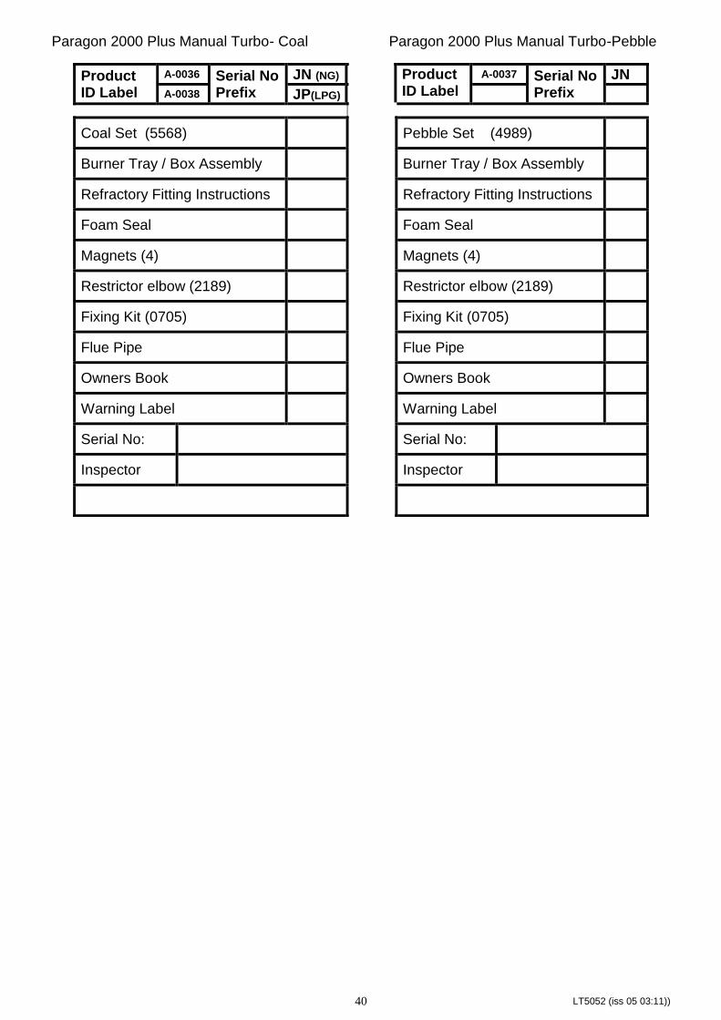
Paragon 2000 Plus Manual Turbo- Coal Paragon 2000 Plus Manual Turbo-Pebble
Product ID Label
A-0036 Serial No Prefix
JN (NG) Product ID Label
A-0037 Serial No Prefix
JN
A-0038 JP(LPG)
Coal Set (5568) Pebble Set (4989)
Burner Tray / Box Assembly Burner Tray / Box Assembly
Refractory Fitting Instructions Refractory Fitting Instructions
Foam Seal Foam Seal
Magnets (4) Magnets (4)
Restrictor elbow (2189) Restrictor elbow (2189)
Fixing Kit (0705) Fixing Kit (0705)
Flue Pipe Flue Pipe
Owners Book Owners Book
Warning Label Warning Label
Serial No: Serial No:
Inspector Inspector