parabolic trough technology vs tower technology
TRANSCRIPT

Copyright © Abengoa Solar, S.A. 2015. All rights reserved
Innovative Technology Solutions for Sustainability
ABENGOA
SOLAR
Innovative Technology Solutions for Sustainability
Solar Thermal Energy: I. Parabolic Trough Technology II. Tower Technology
Copyright © Abengoa Solar, S.A. 2015. All rights reserved
Introduction
Solar Thermal Technology: Dispatchability as a Stand-out Element
Parabolic Trough Technology
Tower Technology
Copyright © Abengoa Solar, S.A. 2015. All rights reserved
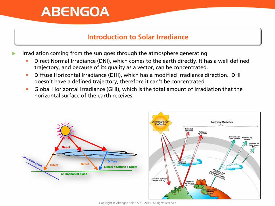
Introduction to Solar Irradiance
Irradiation coming from the sun goes through the atmosphere generating:
Direct Normal Irradiance (DNI), which comes to the earth directly. It has a well defined trajectory, and because of its quality as a vector, can be concentrated.
Diffuse Horizontal Irradiance (DHI), which has a modified irradiance direction. DHI doesn’t have a defined trajectory, therefore it can’t be concentrated.
Global Horizontal Irradiance (GHI), which is the total amount of irradiation that the horizontal surface of the earth receives.
Direct
Diffuse
Global = Diffuse + DirectDirect Direct
on horizontal plane
on normal plane
Direct
Diffuse
Global = Diffuse + DirectDirect Direct
on horizontal plane
on normal plane

Copyright © Abengoa Solar, S.A. 2015. All rights reserved
Distribution of Direct Normal Irradiance (DNI)

Copyright © Abengoa Solar, S.A. 2015. All rights reserved
Introduction
Solar Thermal Technology: Dispatchability as a Stand-out Element
Parabolic Trough Technology
Tower Technology
Copyright © Abengoa Solar, S.A. 2015. All rights reserved
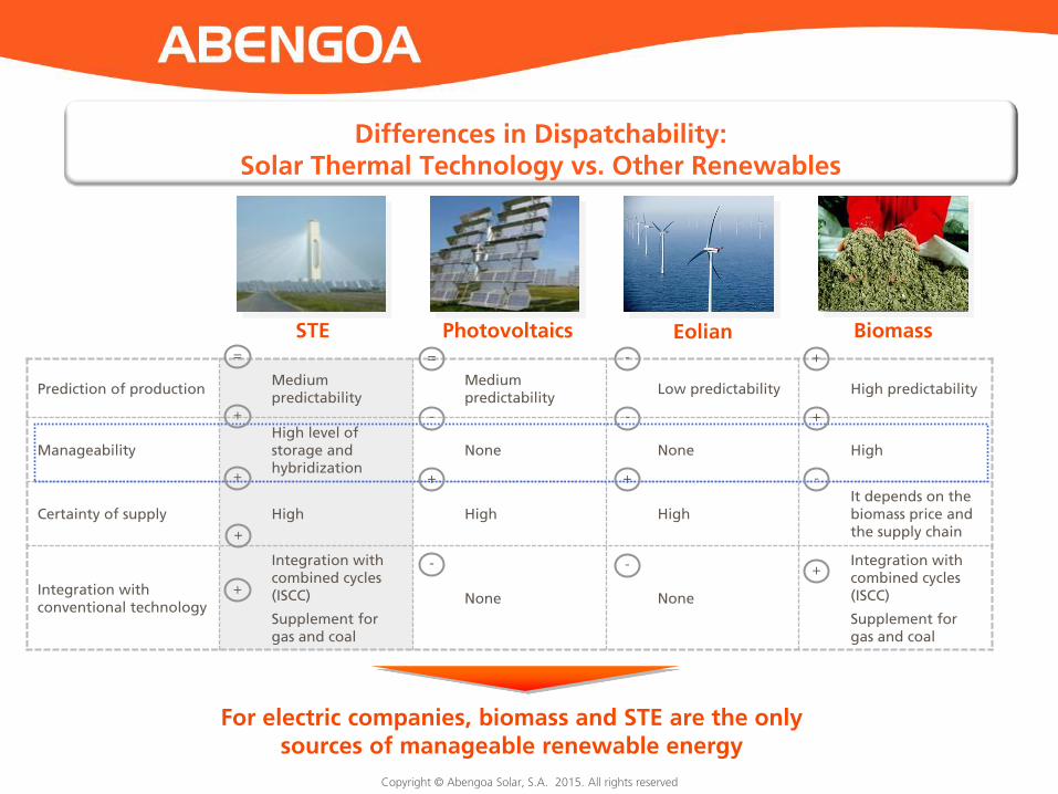
Prediction of production Medium predictability
Medium predictability
Low predictability High predictability
Manageability High level of storage and hybridization
None None High
Certainty of supply High High High It depends on the biomass price and the supply chain
Integration with conventional technology
Integration with combined cycles (ISCC)
Supplement for gas and coal
None None
Integration with combined cycles (ISCC)
Supplement for gas and coal
STE Photovoltaics Eolian Biomass
For electric companies, biomass and STE are the only sources of manageable renewable energy
=
+
+
+
=
-
+
-
-
-
+
-
+
+
-
+
+
Differences in Dispatchability: Solar Thermal Technology vs. Other Renewables

Copyright © Abengoa Solar, S.A. 2015. All rights reserved
• Parabolic trough and tower are the commercial technologies that generate electricity on a large scale • Fresnel and disco Stirling technologies provide potential for others uses
+
Parabolic trough Tower Fresnel Disco Stirling
Parabolic trough collectors concentrate solar irradiation in a receiver tube which contains a Heat Transfer Fluid (HTF).
Matureness
Heliostats follow the sun and reflect the irradiation at the top of the tower, where the heat is transferred to a Heat Transfer Fluid (HTF).
Fresnel mirrors concentrate the irradiation onto a receiver tube, which contains a Heat Transfer Fluid (HTF).
A group of Disco parabolic mirrors reflects the irradiation on an engine, located in the focal point.
-
Description
Track record
Application
Main quality
30 years
Electricity production on a large scale
Modular
8 years
Electricity production on a large scale
High temperatures
3 years
Heat (mainly)
Low cost
Commercially tested to generate electricity on a commercial scale
Validation
Distributed energy
High capacity of conversion

Copyright © Abengoa Solar, S.A. 2015. All rights reserved 8
Introduction
Solar Thermal Technology: Dispatchability as a Stand-out Element
Parabolic Trough Technology
Tower Technology
Copyright © Abengoa Solar, S.A. 2015. All rights reserved
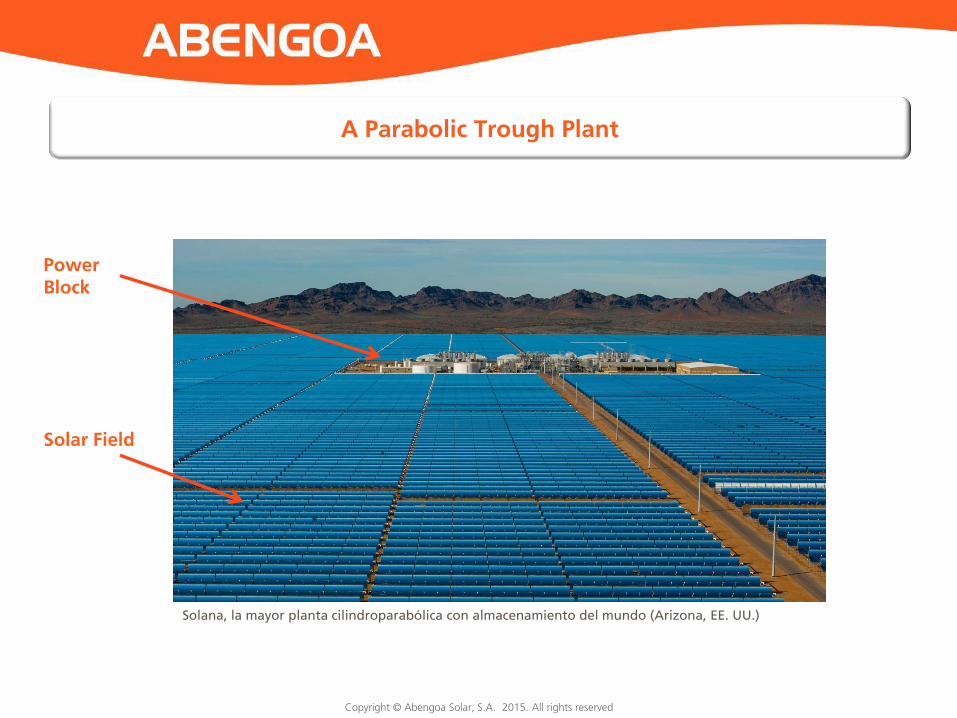
A Parabolic Trough Plant
Power Block
Solar Field
Solana, la mayor planta cilindroparabólica con almacenamiento del mundo (Arizona, EE. UU.)

Copyright © Abengoa Solar, S.A. 2015. All rights reserved
Scheme of a Conventional Parabolic Trough Plant
Evaporator

Copyright © Abengoa Solar, S.A. 2015. All rights reserved Copyright © Abengoa Solar, S.A. 2012. All rights reserved
Solar Field Collector
Storage system Power block

Copyright © Abengoa Solar, S.A. 2015. All rights reserved
Solar Field
A group of parabolic trough collectors capture the solar energy and carries it to the power block, where the heat energy is used to produce steam.

Copyright © Abengoa Solar, S.A. 2015. All rights reserved
Parabolic Trough Collector
The main elements of a parabolic trough collector are:
Foundation and support frame
Reflective surface
Absorbent tubes
Track system
Hydraulic system
Instrumentation and control
Parabolic trough collectors concentrate solar irradiation onto a point or line where the receiver is situated. It transfers the heat to the Heat Transfer Fluid (HTF). The parabolic trough collectors are organized in lines and oriented towards north and south, so they follow the sun on one axis.

Copyright © Abengoa Solar, S.A. 2015. All rights reserved
Parabolic Trough Collector
A complete parabolic trough collector is formed by 10 or 12 modules.
A collector module is formed by 28 mirrors (4 lines and 7 columns).
Parabolic trough collectors are coupled in loops in order to keep a continuous heating process in each plant. A loop is formed by 4 collectors.
Copyright © Abengoa Solar, S.A. 2015. All rights reserved
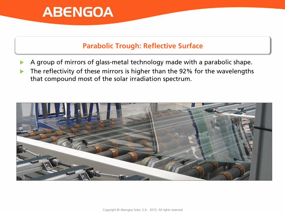
Parabolic Trough: Reflective Surface
A group of mirrors of glass-metal technology made with a parabolic shape.
The reflectivity of these mirrors is higher than the 92% for the wavelengths that compound most of the solar irradiation spectrum.

Copyright © Abengoa Solar, S.A. 2015. All rights reserved
Absorbent Tubes
The absorbent tube is one of the most important elements in every parabolic trough collector. It is formed by these elements:
The absorbent tube which is made of stainless steel, with a selective coating where the Heat Transfer Fluid (HTF) circulates.
A glass tube with an non-reflexive coating for a better solar transmission. The vacuum between the absorbent tube and the glass tube eliminates the heat spread.
Dilatator (bellows) absorbs the thermal expansions.
A Getter maintains the vacuum.

Copyright © Abengoa Solar, S.A. 2015. All rights reserved
Power Block
Storage tanks Cooling tower Water treatment plant
Turbine

Copyright © Abengoa Solar, S.A. 2015. All rights reserved
Examples of Parabolic Trough Plants
Solana • Arizona, U.S. • 280 MW • 6 h molten salts storage • Parabolic trough technology • Operational since 2013
Solar Extremadura Complex • Extremadura, Spain • 4 plants of 50 MW • Parabolic trough technology • Solaben 2 & Solaben 3: operational since 2012 • Solaben 1 & Solaben 6: operational since 2013
KaXu Solar One • Northern Cape, South Africa • 100 MW • 2,5 h molten salts storage • Parabolic trough technology • Operational since 2015

Copyright © Abengoa Solar, S.A. 2015. All rights reserved
Introduction
Solar Thermal Technology: Dispatchability as a Stand-out Element
Parabolic Trough Technology
Tower Technology

Copyright © Abengoa Solar, S.A. 2015. All rights reserved
Scheme of Tower Plants
Evaporator
Molten Salt Tower
Super-heated Steam Tower

Copyright © Abengoa Solar, S.A. 2015. All rights reserved
Scheme of a Parabolic Trough Plant
Power Block
Solar Field
PS10, the world’s first operational commercial tower

Copyright © Abengoa Solar, S.A. 2015. All rights reserved Copyright © Abengoa Solar, S.A. 2012. All rights reserved
Sections and Components of a Tower Plant
Solar Field Receiver
Storage System Power Block
Copyright © Abengoa Solar, S.A. 2015. All rights reserved
23
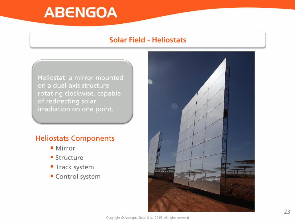
Heliostat: a mirror mounted on a dual-axis structure rotating clockwise, capable of redirecting solar irradiation on one point.
Solar Field - Heliostats
Heliostats Components Mirror
Structure
Track system
Control system
Copyright © Abengoa Solar, S.A. 2015. All rights reserved
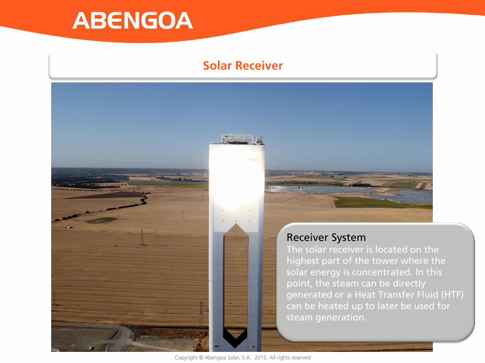
Solar Receiver
Receiver System The solar receiver is located on the highest part of the tower where the solar energy is concentrated. In this point, the steam can be directly generated or a Heat Transfer Fluid (HTF) can be heated up to later be used for steam generation.

Copyright © Abengoa Solar, S.A. 2015. All rights reserved
Steam storage tanks at Khi Solar One (Northern Cape, South Africa). This allows this solar thermal plant to produce 50 MW for two hours.
Thermal energy storage tanks in molten salts in Solana (Arizona, U.S.). This system allows the plant to produce 280 MW for 6 hours.
Different kinds of storage systems There are usually two storage technologies at solar thermal tower plants. These are steam storage tanks, or, for a plant that needs 3 or more ours of storage, molten salt tanks.

Copyright © Abengoa Solar, S.A. 2015. All rights reserved
Turbine
Storage tanks
Cooling tower
Water treatment plant
PS20, la segunda planta comercial del mundo, entró en operación en 2009

Copyright © Abengoa Solar, S.A. 2015. All rights reserved
PS10 1
• 11 MW • Storage • Receiver’s technology: saturated steam • Operational since June 2007 • 624 heliostats, of120 m2 each • 6.700 tCO2 avoided per year
PS20
• 20 MW • Storage • Receiver’s technology: saturated steam • Operational since May 2009 • 1.255 heliostats, of 120m2 each • 12.100 tCO2 avoided per year
2
ABENGOA SOLAR

Copyright © Abengoa Solar, S.A. 2015. All rights reserved
Generation of superheated steam at the receiver maximizes the efficiency of the technology.
Characteristics:
50 MW
Steam storage
Superheater + 2 systems of evaporation
Natural draft cooling system
A 200 m high tower
A 4120 heliostats solar field
19 steam storage tanks
Khi Solar One: superheated steam tower
Copyright © Abengoa Solar, S.A. 2015. All rights reserved
Copyright © Abengoa Solar, S.A. 2015. All rights reserved
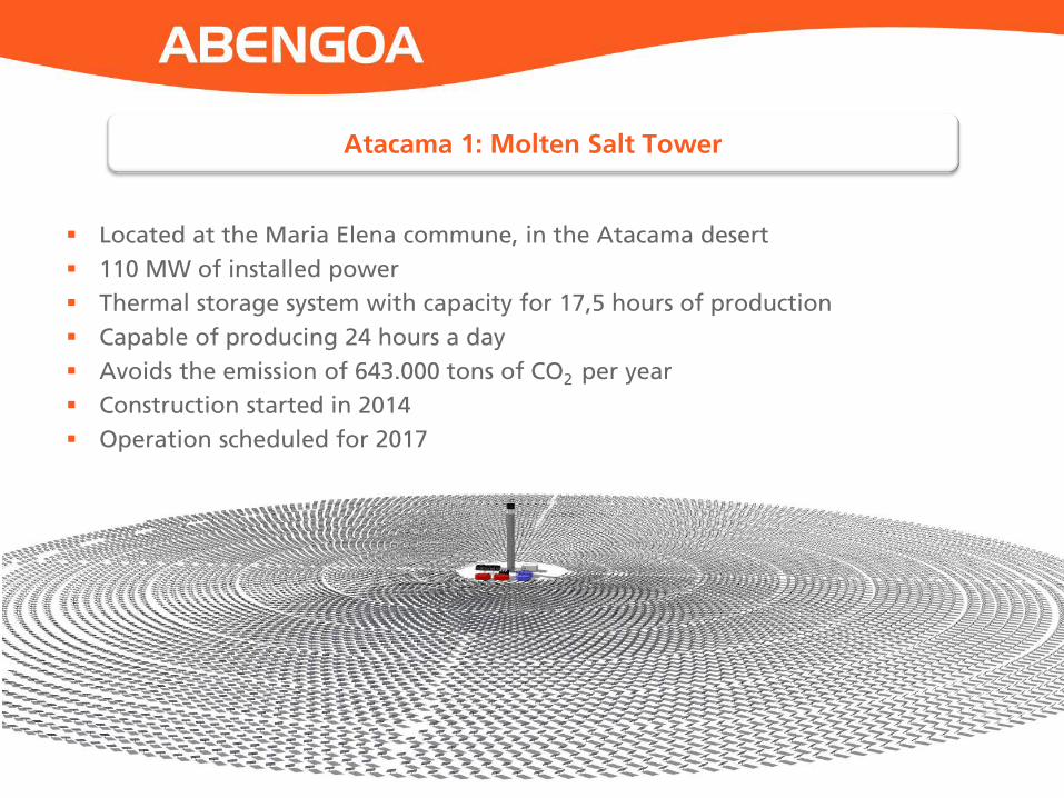
Located at the Maria Elena commune, in the Atacama desert
110 MW of installed power
Thermal storage system with capacity for 17,5 hours of production
Capable of producing 24 hours a day
Avoids the emission of 643.000 tons of CO2 per year
Construction started in 2014
Operation scheduled for 2017
Atacama 1: Molten Salt Tower