papers - imesa · only in providing employment with opportunities of new skills, but it will ... a...
TRANSCRIPT

� � �IMESA
� � � � � � � � � � � � � � � � �Graham Isaac
WorleyParsons RSA – Lead designers
Sub-contracted to Basil Read – Main Contractor
INTRODUCTION
The St Helena Airport Project provides many unique and unusual features
requiring advanced engineering ingenuity and planning. The remote
location of the island has major logistical considerations as almost eve-
rything, excluding rock and water, has to be shipped to the island. The
island’s heritage and fragile environment provides a signi�cant legacy of
international acclaim requiring preservation and particular awareness in
detailing aspects of the project’s design and construction processes.
Although construction works for the Airport continue through to Feb-
ruary 2016 many of the associated infrastructure works are well under-
way with the detail design work scheduled for completion at the end of
PURPOSE OF THE PROJECT
St Helena is one of the most geographically isolated islands in the world
only access has been by sea with the current maximum size and weight
of any single component having to be transported by the mail ship, the
is transported ashore using towed barges and passengers are ferried to
and from the ship by small launches.
The economic viability of St Helena is dependent on the frequency and
reliability of access for people and goods to the island. The airport project
is destined to change the lives of all St Helenians, known as Siants, not
only in providing employment with opportunities of new skills, but it will
boost the island’s economic growth with increased tourism and stimulate
the expansion of support industries.
AIRPORT INFRASTRUCTURE DESIGN ASPECTS
Landside Engineering
The remoteness of the island, its size, logistics of materials supply, unique
geology, topography and climate, endemic biodiversity with sensitive
environmental heritage, ethnic diversity and history have all prompted
innovation in the design of speci�c aspects of the Project Infrastructure.
In addition the project design features required careful consideration of
appropriate constructability and programming of design delivery requir-
ing close integration of the design and construction team members. Fea-
tures of the project consist of the following:
as St Helena has no permanent wharf facility.
-
mands (1.5 million litres facility).
terrain with a maximum vertical grade of 15% and cross slopes of 1 in
-
structed largely in cut.
-
at the southern end of the runway (with 100 m high terraced pro�le re-
quiring 8 million m ). This aspect of the project presented the biggest
challenge in ensuring stringent �nal level tolerances in supporting a
-
tion below for a more detailed description of the design and construc-
tion process.
- Associated with the rock�ll processing, borehole explorations were
conducted to source suitable yielding groundwater, and the con-
lined facilities).
catchment area to facilitate controlled stream-"ow release upstream of
a 2.0 m x 680 m long concrete box culvert.
- Structural design considerations for the required 120 year de-
sign life with use of appropriate and proven performances from
concrete additives.
- Further value engineering has resulted in this structure being re-
placed with an open channel drain with the excavated material being
available landing distance.
-
tion, thermal modelling, cooling via mechanical ventilation and wet
services to the Airport Terminal Building, Air Tra#c Control Tower and
Fire Services.
Dry Gut Rock!ll Embankment
The strength and settlement characteristics of the available materials to
be used in the rock�ll determined the side slopes and construction pro-
cessing performance of the �ll embankment.
The total of approximately eight million cubic meters of �ll required for
the construction of the airport platform was sourced within the Airport
which was a steep-sided valley at the southern end of the runway plat-
settlement needed to be minimised.
Only rock that required blasting to excavate was used for the �ll as no
other material has been characterised and proven suitable by testing.
�ll areas where settlement considerations were not critical.
Design Criteria
was speci�ed as follows:
straight edge
As the works were considered similar to the construction of a rock�ll dam,
it was proposed that the philosophy de�ned in the following publications
allowable factor of safety (FOS) for slope stability analysis.
In the �rst Section – use of rock, the following is stated:
to consider a wide range of issues including materials, environmental condi-
tions, construction methodology, maintenance regime (..)”
The same principle as above applies to rock�ll dams. In rock�ll struc-
tures the aim is to compact the material to form a dense matrix and

� � � IMESA
maximise settlement during compaction as well as the interlock between
large hard rock particles. In line with rock�ll dam construction methodol-
ogy, it was proposed to use a construction method based speci�cation.
This method has since been re�ned following the results of �eld tests
during the construction process and following extensive trials on site
particularly during the early stages of the �ll construction. Settlement of
the �ll matrix has been continuously monitored once the �ll depth ex-
ceeded about 20 m. The monitored settlement is to be taken into consid-
eration when determining the �nal construction levels to accommodate
the projected settlement and hence ensure that the upper surface of the
�ll remains within the prescribed tolerances throughout its design life.
Site Investigations
Field Survey Controls
The control system used for the survey was based on the St Helena Local
Co-ordinate system and consists of 18 Beacons covering the footprint of
Processed Kinematic GPS data (PPK), GPS survey methods.
Geotechnical Site Investigations
Geotechnical investigations were conducted on Prosperous Plain and
discontinuity surveys and results of the analysis of the borehole core logs
and laboratory data for the proposed air�eld earthworks.
In general the broad material types were mapped with the following
(hillwash) and residual lava
within the lava rock. These could be seen along the steep slopes, where
the rock exposure were “layered” by these bands of softer material
volcanic rocks. This material was further tested to determine whether
suitable for use in the bulk �ll or discarded as spoil
-
ered to unweathered.
Construction Water
At the initial stages of the contract extensive groundwater investigations
were conducted in the vicinity of Prosperous Bay Plain to determine the
prospects of providing the ultimate construction water requirements
the air�eld and surrounding areas with pump tests indicating positive
groundwater yields for construction water requirements.
Seismic Hazard Analysis
area, it was not possible to perform the usual probabilistic analysis and
consequently a deterministic seismic hazard analysis was performed by
Prof. Andrzes Kilko for the project requirements.
The outcome of the analysis indicated that the island has a low seis-
mic hazard potential and the predicted mean Peak Ground Acceleration
(PGA) is 0.021 g and the upper limit (maximum) PGA is 0.05 g.
Analysis of Source Material
was to be excavated, would be very hard with UCS of 100 MPa and may
not break down during processing of the �ll materials. This material con-
sisted mainly of Trachyandesite (average speci�c gravity of 2.6).
soft or decomposed rock, i.e. rock with a UCS of less than 100 MPa which
would probably break down during processing.
-
proximately 80% of both hard and soft material to have a nominal
diameter smaller than 400 mm.
was considered essential to monitor any creep settlement for a period
of approximately 6 months prior to proceeding with the runway surfac-
Materials Performance and Method of Construction
constructed, using di$erent combinations of material types, sourced
from the cut zones. The water quantity added was varied and di$er-
ent compaction e$orts with the equipment available verifying the best
placing methodology.
-
sically two embankment zones, viz. an inner zone directly under the
runway and an outer zone forming the outer embankment slopes. A
third zone was also proposed between the natural valley slopes and the
zone. The minimum �ll layer thickness was determined by the maximum
material particle size allowed, with the maximum particle size not ex-
ceeding two-thirds of the layer thickness.
-
mal excavation and placing process. The composition of the source ma-
terial was expected to vary signi�cantly and was tested in the �eld at
various source locations. A 60% of harder trachyandesite rock to 40%
softer basalt rock was considered desirable.
/m to
100 /m as the anticipated water application to achieve the lowest void
ratio during compaction, which would minimize settlement. The pro-
cessing of the �ll and water application was best determined during the
trial embankment tests to determine the optimum compactive e$ort.
10 roller passes being the optimum number to achieve the required
compaction to compact an 800 mm layer to at least 80% relative density
as a target density for all zones of the embankment.
– approximately 15 000 m to 20 000 m per day utilizing a double shift
24 hour day production strategy.
order to have su#cient volume of this material for placing in the outer
sloped embankment areas. The softer basalt rock was selected for mix-
Trial Embankment Construction and Testing
On establishment of the construction plant on the air�eld site an initial
tested extensively to determine the degree of compaction that could
be attained using various construction procedures for the bulk �ll. Con-
sideration was given to the in"uence on compaction of layer thickness,
addition of water into the rock�ll and number of passes of the 20 tonne
smooth-drum vibrating rollers.
The values adopted for each of the three variables, to cover the range of
expected optimal values, were:
, 80 , 120 .
Surface levels of the ITE were accurately recorded at various stages of
placement and compaction of each layer to determine the changes in
surface level and assess e$ectiveness of the compaction.

� � �IMESA
Plate load tests were conducted on the upper surface of representative
compacted layers and large diameter water-replacement density tests
were conducted in the upper layer of the completed embankment. The
purpose of the plate load tests was to assess their potential application
for Quality Assurance purposes. The density tests are an important part
of the ITE investigation as they obtain actual parameters applicable to the
rock�ll materials and their behavior.
-
ings of the ITE test procedures. The test results indicated the most e$ec-
tive construction application for the material sourced at that time, and
considering an 800 mm thick layer compacted by 10 roller passes after
80 /m of water being added.
Grading of Rock!ll Materials
On consideration of the materials available it was recommended that
only three di$erent categories of material be used for the construction of
the rock�ll embankment, viz. Material 1 in the bulk of the embankment,
Material 2 on the exposed embankment slopes for added slope stability
the rock�ll embankment to provide the lowest resistance against "ow
All materials were to be targeted with a �nes content of less that 5%,
however dependent upon where the material was to be placed in the
construction pro�le it was considered that material with a �nes content
no greater than 15% would still be suitable for use as general �ll, as long
as point-to-point contact would still be achieved for particles larger
that 50 mm.
The target grading for all materials were to be “well graded” with re-
spect to gravel content - where Coe#cient of Uniformity (Cu) > 4, and
material. However, it was considered that “poorly graded” material
would also be acceptable as long as the general grading was within the
envisaged ranges.
Material 1 – the bulk of the rock�ll embankment and composed of a
blend of the uncontrolled blasted hard rock and the softer rock materials
that were excavated – “well graded” material.
Material 2 – consisted of the hard rock material only – “well graded”
material. A suitable volume of this type of material was stockpiled sepa-
rately to ensure the required volume was available for the construction of
the outer section of the bench slopes. Material 2 was placed in a 4 m to
5 m thick zone on the outer surface of the bench slopes from the bottom
to the top of the rock�ll embankment. The target grading of Material 2
that point-to-point contact was retained for particle sizes greater than
50 mm.
Material 3 - the drainage layer which was required in the base of the
-
ley sides – “poorly graded” material.
A graphical display of the proposed grading limits for the rock�ll mate-
rial is shown in the �gure below.
Rock!ll Embankment Slope Stability
A detailed analyses was performed to evaluate the possibility of e$ect-
ing cost savings by steepening the embankment slopes. The US Corps of
Engineers approach for dams was used, which de�nes 1.5 as an allowable
FOS for embankment slope analysis.
Without the availability of conclusive laboratory tests at the initial stag-
es of the project to guide the selection of shear strength parameters to
use in the slope stability analysis, empirical methods were used to derive
-
lowing relationship can be used to determine the shear strength param-
0 – φ log , where:
σ
1 atmosphere
φ : the friction angleφ
0
φ : the correction for con�ning pressure variation
σ : con�ning pressure in the �ll
From several laboratory test results on materials from various dams
the typical φ0 and φ ranges can be determined as summarised in the
table below:
Material φ0
�φ
�100
50
55
45
10
8
Gravel100
50
51
41
8
3
For the case of high internal con�ning pressures (say �ll height > 50 m)
it can be shown that φ may vary between 41�
and 45� for rock�ll at between 50% and 100%
relative density, while the corresponding val-
ues for gravel may vary between 40� �
.
relative density. The composition of the rock-
-
bankment contained a substantial amount of � was proposed
as an acceptable shear strength parameter for
deeper seated failures. A bulk rock�ll density
of 2 150 kg/m was used.
analysis, shallow slope failures with low fac-
tors of safety are the most critical, as was the
case for the bench slopes selected. In this case
the con�ning pressures were much lower and � and
52� (44
� and 48
� for gravel). It was therefore

� � � IMESA
� � should be used in such analysis and still
with the values and ranges as recorded in the table above.
The proposed rock�ll embankment slope geometry was as follows:
surface between benches, which equates to an average (relative) slope
The �rst phase of the slope stability evaluation revolved around the sta-
bility of the individual bench slopes (Material 2), for which the following
parameters were used: � �The results of this slope stability evaluation are summarised in
Table 1 below.
TABLE 1 Stability of Bench Slope
φ�
Factor of SafetyFailure Surface Distance
10 46 1.46 0.5
10 46 1.49 1.0
10 47 1.50 0.5
10 49 1.61 0.5
10 49 1.65 1.0
11 46 1.45 0.5
11 47 1.50 0.5
11 49 1061 0.5
12 46 1.45 0.5
12 47 1.50 0.5
12 49 1.61 0.5
13 46 1.44 0.5
13 47 1.49 0.5
13 49 1.60 0.5
15 46 1.44 0.5
15 47 1.49 0.5
15 49 1.60 0.5
It follows from these results that it would be possible to increase the
bench height of 15 m may even be acceptable.
The second phase of the slope stability evaluation concerned the stabil-
ity of the overall slope (Material 1), for which the following parameters
were used: � �15 m bench)
Stability table not recorded in this paper buy it followed that an overall � to 42
�rock�ll embankment slope would be stable (FS>1.5) for all the cases that
the embankment slope would also be stable (FS > 1.5) for all the cases
analysed, although a cohesion (c) of a minimum of 10 kPa was required
in some cases.
The third phase of the slope stability evaluation considered the stabil-
Earth system. The results of this slope stability evaluation are summarised
in Table 2, with the same parameters as indicated above.
TABLE 2
Slope Reinforced Slope
Friction
Angle
φ� Cohesion
Factor
of
Safety
Failure Surf. Dist.
110 0 40 0 1.50 4
110 0 40 10 1.63 4
110 0 42 0 1.60 4
80 0 40 0 1.51 4
80 0 42 0 1.62 4
50 0 40 0 1.52 4
50 0 42 0 1.64 4
30 0 40 0 1.54 4
30 0 42 0 1.66 4
20 0 40 0 1.58 4
20 0 42 0 1.69 4
-
ysis indications were that the island has a low seismic hazard potential
and the predicted mean Peak Ground Acceleration (PGA) is 0.021 g and
the upper limit (maximum) PGA is 0.05 g.
-
quake (MCE) with 10 000 years recurrence interval will be de�ned to ob-
tain the PGA for design. However with a deterministic analysis it is not
possible to de�ne these earthquakes. The 0.05 g was therefore proposed
as the absolute maximum PGA to be expected and should therefore be
of the airport buildings.
In terms of dam designs the safety is evaluated to achieve a FS of at least
of 0.05 g, the dam may only be designed for a FS >1.5 at 0.05 g, without
giving attention to the MCE.
For the rock�ll slopes some stability calculations were performed for
both these values. For the 10 m high bench slope the following became
clear with a pseudo static analysis:
Slope φ FS
Failure Surf.
Dist. from FS Slope FS
0.021 g 0.05 g 0 g 0.021 g 0.05 g
46 1.38 1.30 0.5 1.46 1.52 1.43
46 1.42 1.34 1.0 1.49 1.56 1.46
47 1.43 1.35 0.5 1.50 1.57 1.48
49 1.54 1.45 0.5 1.61 1.69 1.59
49 1.58 1.49 1.0 1.65� applies to a rock�ll with high gravel � �
applies to rock�ll with low gravel content
(hence the use of low gravel content material on the exposed embank-
ment slopes). The implications were therefore very simple; by ensuring
was therefore most essential to ensure low gravel content rock�ll was
used on the exposed embankment slopes (Material 2 – reference table 1
above) otherwise the slope was to have been "attened to 1:1.5 for use of
the high gravel content materials.
40� �
was acceptable. For 0.05 g the FS is lower but acceptable.

� � �IMESA
The lower FOS results were for the areas closer to the edges of the �ll
embankment where according to our interpretation the live loads are not
applicable. Only working loads were used, because ultimate state design
-
plied at the surface.
The shear strength parameters of the material excavated were retested
once exposed in the initial stages of the excavations to verify the above
mentioned analysis. The following tests and observations were con-
ducted on the initial trial embankment procedure and repeated for any
change in material composition to verify the material characteristics and
performance (initially at a frequency of approximately 50 000m intervals,
and once a level of consistency was achieved every 100 000m during the
construction progression:
the external embankment terraces were physically monitored after �ll-
Settlement
It is very di#cult to quantitatively predict the settlement of a rock�ll em-
bankment and therefore the experience gained at di$erent rock�ll dams
in Southern Africa, was considered together with international experi-
lifespan of at least 120 years and these structures are designed and con-
structed for minimum post-construction settlement.
The embankment settlement is being determined by regular assess-
ment of installed settlement monitoring equipment and geodetic survey
measurements during the construction phase. This data together with
numerical analysis provide con�dence in the construction methods used
and in determining the �nal construction levels to accommodate the
projected settlement and hence ensure that the upper surface of the �ll
remains within the prescribed tolerances throughout its design life.
Monitoring of Rock!ll Settlement and Compaction Control
In order to accurately assess the rate of settlement of the rock�ll a series
of tests are being conducted during the construction with regular moni-
toring of stage lift maximum layerworks depths. Wash-out trial tests are
also conducted at various stages to monitor the optimum water demand
required to achieve interlocking of the rock fragments.
Samples of the blasted rock materials are regularly tested for strength
and durability to ensure that the best quality rock is selected for construc-
tion of the exposed embankment faces. Other tests for quality control
records included mass density tests, plate bearing tests, water absorp-
tion and porosity, Atterberg limits, UCS, point load tests, pH and water
soluble Sulphates to con�rm that there is no potential for degradation
of the source materials. A fully equipped materials laboratory was es-
tablished on site to accommodate calibration of equipment and the
standard method of testing of all in-situ materials and the monitoring of
construction workmanship and materials performance requirements, all
in accordance with the speci�cations of UK Highways Works, Series 600
in accordance with the following speci�cations:
1 test per 50 000 m material placed.
100 000 m material placed.
AB Engineering Inc., Littleton, Colorado, USA
Stormwater Drainage
interface of the toe of the �ll with the natural rock valley sides considera-
tion was made for directing all stormwater runo$ from the air�eld foot-
print away from the �ll matrix and channel the outlets to convenient loca-
tions along natural contours and into the neighbouring water courses.
Also of note was that an open channel drain was excavated into the
Gut catchment into the neighbouring valley, thus resulting in the omis-
Balance of Earthworks, Design Drawings and Volume Calculations
Taking cognizance of the design criteria, the anticipated source material
-
ings of the Air�eld Earthworks were developed. The surfaces of the em-
bankment pro�les and volume calculations were generated from Model
Maker TOT �les of the site survey data. In view of the initial uncertainty
of the ultimate performance of the source materials a sensitivity analysis
was computed using various combinations of the design criteria.
In view of the critical path programme, �xing the �nal vertical align-
ment of the runway was considered vital considering the lead time re-
quired in setting up the procedures of the necessary "ight path sensitivity
analysis and the follow-on requirements of developing early submissions
-
grammed on the basis of our �nal design alignment con�guration and
balance of earthworks. As such any later adjustment to this alignment will
have serious time delay consequences to the Construction programme.
The earthworks volume sensitivity analysis clearly showed that the
slightest variation in the material performance had a marked e$ect on
the material balance.
Airside/ Aviation
The airport design is challenging and requiring the following innovative
design considerations:
- innovative design to ensure that an aircraft can safely land with suf-
�cient fuel to return to the originating airport.
- careful consideration of selection of navigation aids and operating
procedures to ensure that the likelihood of an aborted landing is con-
tained within an absolute minimum landing space.
presents challenges in:
- Cost e$ective design to ensure that only necessary infrastructure
is provided.
- Pavement Quality Concrete runway to consider increased "exural
strength with possible reduction in pavement thickness.
- Managing operation costs.
- Maintaining technical and operational expertise, since the work force
may largely be part time.
-
�cult, especially to keep costs and environmental impact in bounds. The
trade-o$s include:
-
ened approach lights, etc.).
- Orientation of runway (to make use of prevailing wind).

� � � IMESA
- Obstacles forcing unconventional angled (o$set) aircraft approaches.
Aids and Airport Tra#c Control Equipment.
Airport Buildings
The design of the Airport Terminal Buildings and their setting in the
landscape attempts to capture and convey the unique spirit of the is-
land in built form. The new buildings have been designed with the
following considerations:
-
rian periods found on the island.
-
ing back to the military history of the island.
plaster. The use of natural materials from the site will anchor the Termi-
nal Buildings within their context. Volcanic ash, pumice, oxides and rock
formations form the very fabric of the island.
on either side of the main entrance. Existing rocks with coloured lichens
are to be harvested from the site prior to building commencement to be
used within the proposed garden courtyards.
-
ture the spirit of the people of St. Helena and create a feeling of inclu-
sivity amongst the Saints. These will consist of wall murals and speci�c
commissions from local artists.
buildings. These include rainwater and grey-water harvesting in tanks
buried below the garden courtyards; solar panels mounted on the roofs
for water heating; passive energy principles including solar shading via
roof overhangs and opening window sections as well as maximum day-
light penetration via roof skylights.
CONSTRUCTION CHALLENGES
The biggest challenge in constructing the St Helena Airport has been
creating and maintaining an e#cient planning and logistics chain. There
was no major construction plant or building materials on the island and
virtually everything having to be shipped to the island. The Main Contrac-
tor has chartered a 2 500 tonne ocean-going vessel for the duration of the
contract to accommodate their plant and materials supply requirements.
The Contractor has set up a consolidation area in Walvis Bay from where
seven to return, owing to currents and winds, with a single shipping cycle
taking up to 21 days to complete.
early works establishments consisted of a temporary fuel facility (1,5 mil-
lion litres), construction of the 14,5 km haul road over very harsh rocky
and steep terrain, sta$ accommodation for 120 persons, borehole explo-
rations in sourcing adequate groundwater for construction water and
the construction of temporary water storage dams (4 x 2 million litre
internationally accredited laboratory, and the erection of crushing and
concrete batching plants. The social interaction and integration with the
local Saints community was an issue that was looked at seriously before
embarking on the contract with the Main Contractor employing about
-
duction the work force will increase to about 450 persons.
Apart from the varying geographical features of the island, the airport
site presents unique challenges owing to the setting and history of St
Helena. There have been protected slave burial sites and archaeological
�nds to contend with, apart from the site being close to the breeding
area of the Wirebird, which is indigenous to St Helena. It is also in close
proximity to around 40 species of invertebrates that can only be found on
the island. Once completed, the challenge remains for the Contractor and
their subcontractors to clean up and remove all hazardous waste gener-
ated by the project, leaving the island as they found it when they arrived.
The risk awareness of the project execution is absolutely crucial for the
success of the project, and both the St Helena Government and the pro-
ject team run and share a comprehensive risk and opportunity register all
identify and mitigate any risks to the Health and Safety of personnel prior
to commencement of any sector of the works. This register is updated
regularly by the St Helena Government and the Contractor’s project team
in an e$ort to ensure that Health and Safety of personnel and the special
features of the island are protected and that the ultimate goal of com-
pleting the contract on time and within budget is achieved.
Annexure A1
Initial Plant Establishment
PHOTO 1
PHOTO 2
� � �IMESA
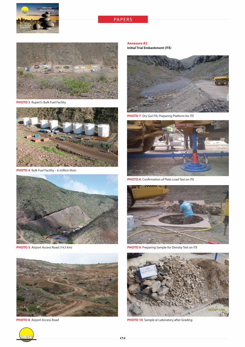
PHOTO 3
PHOTO 4 Bulk Fuel Facility – 6 million litres
PHOTO 5
PHOTO 6
Annexure A2
Initial Trial Embankment (ITE)
PHOTO 7
PHOTO 8 Con� rmation of Plate Load Test on ITE
PHOTO 9
PHOTO 10 Sample at Laboratory after Grading

� � � IMESA
PHOTO 11 Start of Washout Test
PHOTO 12
Annexure A3
General Production
PHOTO 13
PHOTO 14
PHOTO 15
PHOTO 16
PHOTO 17 Airport Terminal and Air Control Buildings
PHOTO 18 Airport Air Control building

� � �IMESA
Annexure B
WPG-720-CI-0001-01-REV 1 Air�eld Bulk Earthworks General Layout
WPG-720-CI-0002-01-REV 2 Air�eld Bulk Earthworks Settlement Monitoring

� � � IMESA
WPG-720-CI-0004-01-REV 2 Air�eld Bulk Earthworks Longitudinal Sections
WPG-720-CI-0003-01-REV 2 Air�eld Bulk Earthworks Typical Sections