paper no. 8898 - matergenics engineering ltd.. … · paper no. 8898 ©2017 by nace international....
TRANSCRIPT
Inspection and Mitigation of Underground Corrosion at Anchor Shafts of Telecommunication Towers
Peyman Taheri Matergenics Engineering Ltd.
320-638 Broughton Street Vancouver, BC V6G 3K3
CANADA
Abraham Mansouri Dept. Mechanical Eng.
American University in Dubai Dubai 28282
UAE
Badia Bachour AltaLink
2611-3rd Avenue SE Calgary, AB T2A 7W7
CANADA
Nitesh Ahuja
SBA Communications Corp. 8051 Congress Avenue
Boca Raton, FL 33487-1307 USA
Mehrooz Zamanzadeh Exova
100 Business Center Drive Pittsburgh, PA 15205
USA
ABSTRACT
Common scenarios for underground corrosion at foundations of telecommunication towers are explained, and practical methods for corrosion risk assessment and corrosion risk mitigation are briefly reviewed. Among different types of corrosion control techniques, cathodic protection is proved to be an efficient and cost-effective method. Accordingly, a new simulation-based approach is proposed to improve the design of cathodic protection systems for foundations of telecom towers, with emphasize on electrochemical characteristics of the service environment and geometry details. Some capabilities of the approach are demonstrated through sample simulations for screw-pile foundations. Keywords: underground corrosion, cathodic protection, electrochemical simulations, telecommunication structures
INTRODUCTION
Steel towers with various designs are favored to support antennas for telecommunication and broadcasting services. Early towers were mostly utilized to meet regional public needs such as broadcasting public radio and television; however, nowadays these structures help millions of wireless services users around the world to connect via cellular networks, satellites, and two-way radios. During recent years, wireless communication has become an essential part of networking for businesses, police forces, firefighters, ambulances, electrical grids, air navigation and national defense systems. Consequently, structural integrity of telecom towers is the key to ensure reliability of telecommunication and broadcasting services; nonetheless, many tower facilities are coming of age and corrosion related issues are turning into serious engineering and economic problems.
1
Paper No.
8898
©2017 by NACE International.Requests for permission to publish this manuscript in any form, in part or in whole, must be in writing toNACE International, Publications Division, 15835 Park Ten Place, Houston, Texas 77084.The material presented and the views expressed in this paper are solely those of the author(s) and are not necessarily endorsed by the Association.

As shown in Figure 1, atmospheric and underground corrosion occur respectively at above-grade and below-grade members of telecom towers; however, the risk of structural failure is mostly associated with below-grade corrosion at buried components of tower foundations, sometimes assisted by mechanical and microbiological actions, depending upon the nature of service environment.
Figure 1: Sample photos of above-grade and below-grade corrosion at telecom towers
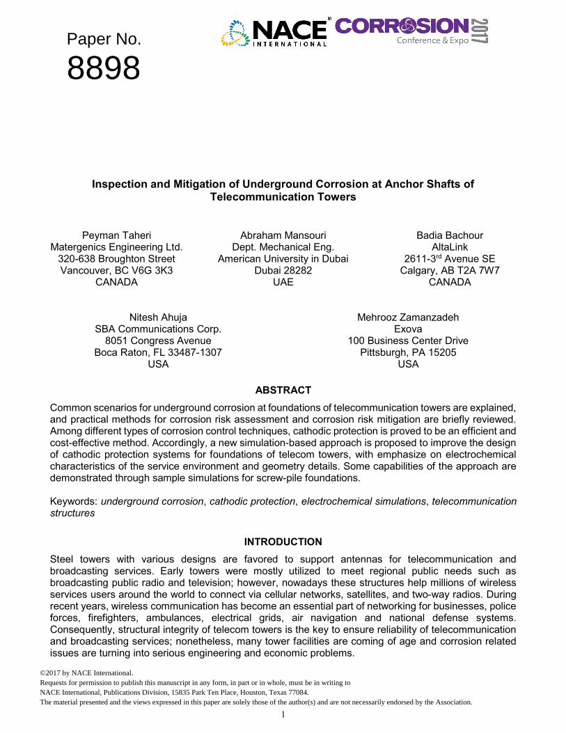
From a structural point of view, telecom structures are divided into two main categories (see Figure 2):
Guyed structures: Lattice towers and masts; poles Self-supporting structures: Lattice towers; poles
Guyed towers are the focus of this study, because they are more popular compared to other types, and represent a wide range of foundation designs. These incredibly tall, yet slender structures have multiple foundations including: i) tower base foundation, which is designed to carry unfactored and factored loads due to wind, weight of tower and mounted equipment, ii) multiple anchor foundations, which provide lateral and uplift supports to hold the tower upright using a series of guy wires. A typical three-sided guyed tower, with 300 to 500 ft. (90 to 150 m) height, has 3 or 6 anchors, and corrosion induced failure at only one of its anchors can compromise the tower stability. Accordingly, this type of towers is more susceptible to failure due to corrosion of their anchor shafts.
2
©2017 by NACE International.Requests for permission to publish this manuscript in any form, in part or in whole, must be in writing toNACE International, Publications Division, 15835 Park Ten Place, Houston, Texas 77084.The material presented and the views expressed in this paper are solely those of the author(s) and are not necessarily endorsed by the Association.
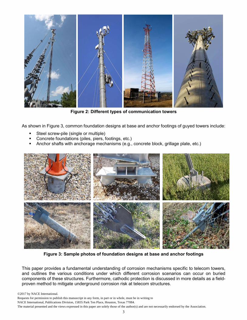
Figure 2: Different types of communication towers
As shown in Figure 3, common foundation designs at base and anchor footings of guyed towers include:
Steel screw-pile (single or multiple) Concrete foundations (piles, piers, footings, etc.) Anchor shafts with anchorage mechanisms (e.g., concrete block, grillage plate, etc.)
Figure 3: Sample photos of foundation designs at base and anchor footings
This paper provides a fundamental understanding of corrosion mechanisms specific to telecom towers, and outlines the various conditions under which different corrosion scenarios can occur on buried components of these structures. Furthermore, cathodic protection is discussed in more details as a field-proven method to mitigate underground corrosion risk at telecom structures.
3
©2017 by NACE International.Requests for permission to publish this manuscript in any form, in part or in whole, must be in writing toNACE International, Publications Division, 15835 Park Ten Place, Houston, Texas 77084.The material presented and the views expressed in this paper are solely those of the author(s) and are not necessarily endorsed by the Association.

UNDERGROUND CORROSION AT TELECOMMUNICATION TOWERS
Corrosion Risk Assessment at Telecom Towers
Soil corrosivity is the most important index to determine the rate of underground corrosion, and it depends on combined effects of the following soil properties:
Soil resistivity, Soil pH level, Soil moisture content, Soil oxygen content (aeration level), Soil texture, Soil temperature, Soil contamination (soluble chemical salts), and Soil micro-organisms.
Severity of underground corrosion at aging telecom towers is usually unknown, unless visual inspections for corrosion risk assessment are performed. The main drawback of visual inspection at tower foundations is the necessity of costly excavations. Telecommunication companies that manage a large population of aging towers, usually prioritize their towers for corrosion inspection based on the level of corrosion risk. To assign a corrosion risk factor (CRF) to each tower, specific importance weights must be assigned to the following parameters:
Tower importance (may include a combination of different factors such as coverage area, type of service, proximity to public, etc.),
Structure age, Foundation type, design, and material, Grounding system design (risk of galvanic corrosion), Corrosivity of soil service environment, Proximity to pipelines and other sources of stray current corrosion, Presence of corrosion control system (coating and/or cathodic protection system), and Inspection and maintenance history.
Based on evaluated CRFs, towers with highest risk factors must be selected for underground corrosion inspections, which may include all or some of the following items:
Structure-to-soil potential measurement, Soil resistivity test (e.g., ASTM G571, ASTM G1872), Soil pH test (e.g., ASTM G513), Excavations and cleaning, Visual inspections of excavated members, and Coating and material thickness measurements (e.g., ASTM G464).
Corrosion Scenarios at Telecom Towers
In Figure 4, an anchor foundation, also known as deadman anchor foundation, is schematically shown. The anchor shaft, usually made from carbon steel or galvanized steel, plays a critical role in structural integrity of the tower. This component is constantly under tensile force as a result of opposing forces at its ends, i.e., tension in guy wires and weight of the anchor block (concrete usually). Accordingly, any form of material loss on anchor shafts leads to decrease of cross-sectional area and formation of ‘stress risers’, which in turn increase the risk of structural failure. Localized material loss due to underground corrosion is known as the main culprit for structural failure in anchor shafts of telecom towers. Common scenarios for structural corrosion in anchor shafts are shown in Figure 4, and discussed below.
4
©2017 by NACE International.Requests for permission to publish this manuscript in any form, in part or in whole, must be in writing toNACE International, Publications Division, 15835 Park Ten Place, Houston, Texas 77084.The material presented and the views expressed in this paper are solely those of the author(s) and are not necessarily endorsed by the Association.
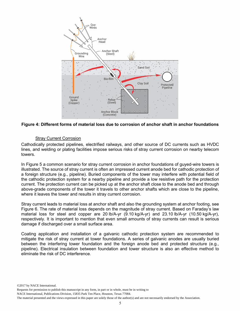
Figure 4: Different forms of material loss due to corrosion of anchor shaft in anchor foundations
Stray Current Corrosion
Cathodically protected pipelines, electrified railways, and other source of DC currents such as HVDC lines, and welding or plating facilities impose serious risks of stray current corrosion on nearby telecom towers. In Figure 5 a common scenario for stray current corrosion in anchor foundations of guyed-wire towers is illustrated. The source of stray current is often an impressed current anode bed for cathodic protection of a foreign structure (e.g., pipeline). Buried components of the tower may interfere with potential field of the cathodic protection system for a nearby pipeline and provide a low resistive path for the protection current. The protection current can be picked up at the anchor shaft close to the anode bed and through above-grade components of the tower it travels to other anchor shafts which are close to the pipeline, where it leaves the tower and results in stray current corrosion. Stray current leads to material loss at anchor shaft and also the grounding system at anchor footing, see Figure 6. The rate of material loss depends on the magnitude of stray current. Based on Faraday’s law material loss for steel and copper are 20 lb/A-yr (9.10 kg/A-yr) and 23.10 lb/A-yr (10.50 kg/A-yr), respectively. It is important to mention that even small amounts of stray currents can result is serious damage if discharged over a small surface area. Coating application and installation of a galvanic cathodic protection system are recommended to mitigate the risk of stray current at tower foundations. A series of galvanic anodes are usually buried between the interfering tower foundation and the foreign anode bed and protected structure (e.g., pipeline). Electrical insulation between foundation and tower structure is also an effective method to eliminate the risk of DC interference.
5
©2017 by NACE International.Requests for permission to publish this manuscript in any form, in part or in whole, must be in writing toNACE International, Publications Division, 15835 Park Ten Place, Houston, Texas 77084.The material presented and the views expressed in this paper are solely those of the author(s) and are not necessarily endorsed by the Association.

Figure 5: Schematic for stray current corrosion at anchor shafts of telecom towers
Figure 6: Excessive material loss on an anchor shaft due to stray current corrosion
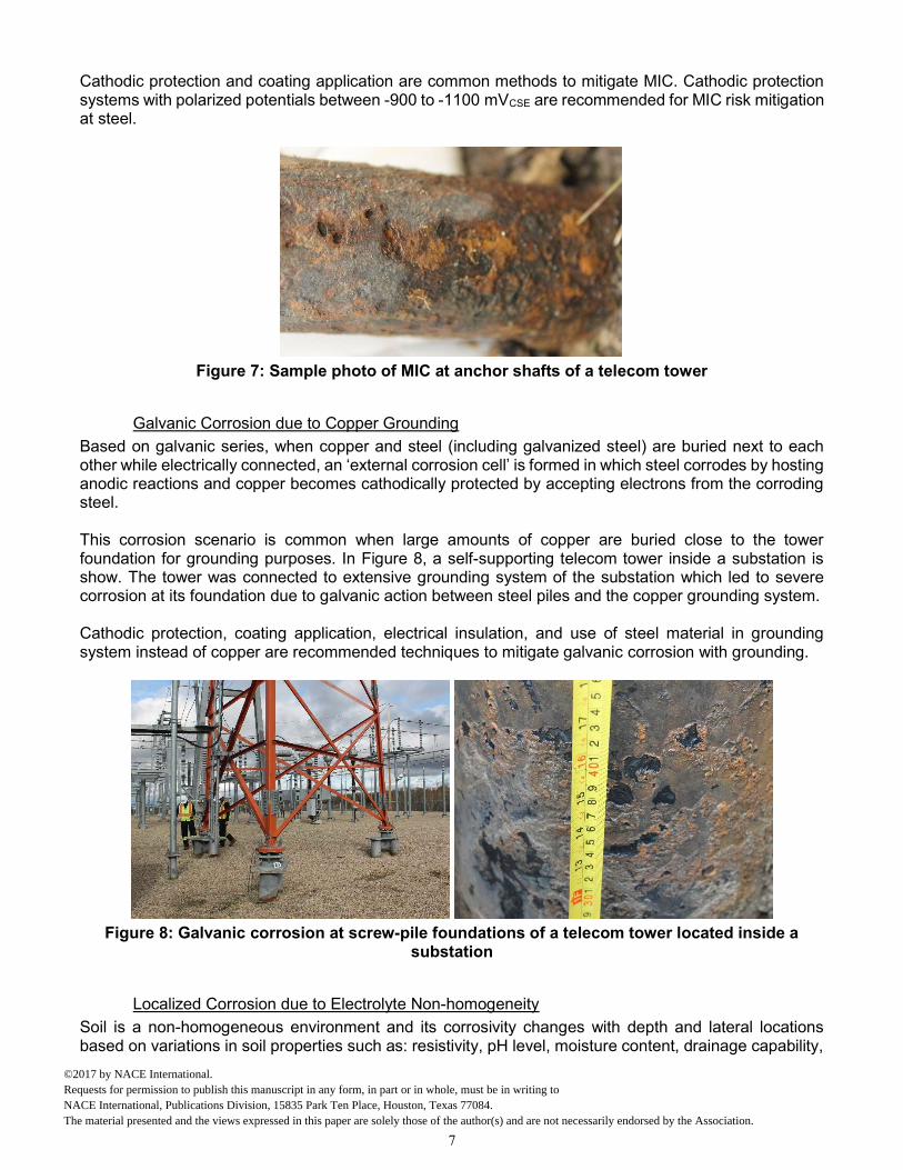
Microbiologically Induced Corrosion (MIC)
There are different types of micro-organisms in soil depending on oxygen content and organic compounds in the soil. These micro-organisms may adhere to the metal surface, colonize, proliferate, form bio-films, and change corrosion parameters through their metabolic processes; see Figure 7. The color of the corrosion products can provide good clues in an investigation of MIC and, probably, the likely species involved.5 Black color, smelly iron sulphide corrosion products may be good indicators of sulfate-reducing bacteria (SRB), while reddish-brown color deposits may indicate iron-oxidizing bacteria (IOB). When iron-reducing bacteria (IRB) are present and actively reducing iron, the dark greenish color is a good indication of the presence of these bacteria. In the case of sulphur-oxidizing bacteria (SOB), the color of the corrosion products is reportedly yellow.
6
©2017 by NACE International.Requests for permission to publish this manuscript in any form, in part or in whole, must be in writing toNACE International, Publications Division, 15835 Park Ten Place, Houston, Texas 77084.The material presented and the views expressed in this paper are solely those of the author(s) and are not necessarily endorsed by the Association.
Cathodic protection and coating application are common methods to mitigate MIC. Cathodic protection systems with polarized potentials between -900 to -1100 mVCSE are recommended for MIC risk mitigation at steel.
Figure 7: Sample photo of MIC at anchor shafts of a telecom tower
Galvanic Corrosion due to Copper Grounding
Based on galvanic series, when copper and steel (including galvanized steel) are buried next to each other while electrically connected, an ‘external corrosion cell’ is formed in which steel corrodes by hosting anodic reactions and copper becomes cathodically protected by accepting electrons from the corroding steel. This corrosion scenario is common when large amounts of copper are buried close to the tower foundation for grounding purposes. In Figure 8, a self-supporting telecom tower inside a substation is show. The tower was connected to extensive grounding system of the substation which led to severe corrosion at its foundation due to galvanic action between steel piles and the copper grounding system. Cathodic protection, coating application, electrical insulation, and use of steel material in grounding system instead of copper are recommended techniques to mitigate galvanic corrosion with grounding.
Figure 8: Galvanic corrosion at screw-pile foundations of a telecom tower located inside a
substation
Localized Corrosion due to Electrolyte Non-homogeneity
Soil is a non-homogeneous environment and its corrosivity changes with depth and lateral locations based on variations in soil properties such as: resistivity, pH level, moisture content, drainage capability,
7
©2017 by NACE International.Requests for permission to publish this manuscript in any form, in part or in whole, must be in writing toNACE International, Publications Division, 15835 Park Ten Place, Houston, Texas 77084.The material presented and the views expressed in this paper are solely those of the author(s) and are not necessarily endorsed by the Association.
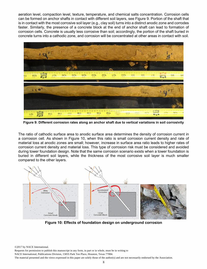
aeration level, compaction level, texture, temperature, and chemical salts concentration. Corrosion cells can be formed on anchor shafts in contact with different soil layers, see Figure 9. Portion of the shaft that is in contact with the most corrosive soil layer (e.g., clay soil) turns into a distinct anodic zone and corrodes faster. Similarly, the presence of a concrete block at the end of anchor shaft can lead to formation of corrosion cells. Concrete is usually less corrosive than soil; accordingly, the portion of the shaft buried in concrete turns into a cathodic zone, and corrosion will be concentrated at other areas in contact with soil.
Figure 9: Different corrosion rates along an anchor shaft due to vertical variations in soil corrosivity
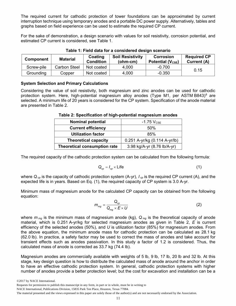
The ratio of cathodic surface area to anodic surface area determines the density of corrosion current in a corrosion cell. As shown in Figure 10, when this ratio is small corrosion current density and rate of material loss at anodic zones are small; however, increase in surface area ratio leads to higher rates of corrosion current density and material loss. This type of corrosion risk must be considered and avoided during tower foundation design. Note that the same corrosion scenario exists when a tower foundation is buried in different soil layers, while the thickness of the most corrosive soil layer is much smaller compared to the other layers.
Figure 10: Effects of foundation design on underground corrosion
8
©2017 by NACE International.Requests for permission to publish this manuscript in any form, in part or in whole, must be in writing toNACE International, Publications Division, 15835 Park Ten Place, Houston, Texas 77084.The material presented and the views expressed in this paper are solely those of the author(s) and are not necessarily endorsed by the Association.

CATHODIC PROTECTION SYSTEM DESIGN
Telecom towers have separated foundations with relatively small surface areas. Therefore, cathodic protection systems with galvanic anodes (magnesium or zinc) are recommended to control underground corrosion at telecom towers. Design of effective CP systems can be a challenging task due to variety in foundation designs, and possibility of different corrosion scenarios, as discussed in the previous section. Screw-piles are becoming popular as foundations for telecom towers, since their installation is fast and inexpensive. Accordingly, in this study, a screw-pile anchor is used to demonstrate the proposed design approach; however, the approach can be extended to any foundation design by applying the following steps:
a) Three-dimensional geometry modeling of foundation, b) Field survey and data collection, c) System selection and primary calculations, d) Finite element electrochemical modeling, and e) Optimization of anode bed design.
Each of above-mentioned steps are discussed below in more details. The primary goal of the proposed design approach is to predict detailed distributions of potential on the buried surfaces of the structure. Such information allows to examine the performance of the CP system and modify the anode bed to sufficiently polarize the structure and meet the NACE criteria for cathodic protection.6 Three-dimensional Geometry Modeling
Three-dimensional CAD models for a few screw-pile designs are shown in Figure 11. Screw-piles are usually made from structural steel (ASTM A2527) and are recommended to be galvanized. Number of helixes, diameter, length, and wall thickness of the piles depend on the tower design, required torque for installation, and soil conditions―screw-piles with 6 to 14 m (20 to 45 ft.) in length and 20 to 45 cm (8 to 18 in.) in outer diameter are common.
Figure 11: Sample CAD models for screw pile foundations (A and B are tower base foundations;
C and D are anchor foundations)
9
©2017 by NACE International.Requests for permission to publish this manuscript in any form, in part or in whole, must be in writing toNACE International, Publications Division, 15835 Park Ten Place, Houston, Texas 77084.The material presented and the views expressed in this paper are solely those of the author(s) and are not necessarily endorsed by the Association.

In Figure 12, a three-dimensional geometry model of an anchor footing with a single screw-pile anchor shaft is depicted. Length of the pile is 9.7 m (32 ft.) and its outer diameter is 32 cm (12.75 in.). A hemisphere of soil around the screw-pile is selected as the main electrolyte domain. Also, an infinite element domain with proper boundary conditions is considered around the main domain to take account for the effects of infinite soil environment. External surface area of the screw-pile in contact with soil is 11 m2 (120 ft.2). The anchor footing includes a grounding system with three spikes, which are connected with a grounding loop. The components of the grounding system (spikes and loop) are made of copper cables and rods with a diameter of 1 inch. Buried surface area of the grounding system is 1.3 m2 (14 ft.2).
Figure 12: Three-dimensional geometry of anchor footing with screw-pile anchor and copper
grounding system
Field Survey and Data Collection
For CP system design, certain tests must be performed on site to collect relevant data, and to characterize the soil service environment. The required measurements include:
a) Soil resistivity measurement, b) Corrosion potential measurement, and c) Cathodic protection current requirement test.
It is recommended to perform soil resistivity tests using Wenner four-pin method1 (ASTM G57 standard) with different pin spacing to evaluate resistivity of different soil layers (Barnes layer analysis) and implement it in the design process. Since distribution of CP current strongly depends on soil resistivity, modeling of CP systems with different soil horizons can make a big difference in simulation results. Corrosion potential (or native potential) is structure-to-soil potential measured with a calibrated reference electrode. The corrosion potential is a strong function of age, steel material, grounding system design, and corrosivity of soil service environment. With increase in soil corrosivity, corrosion potential shifts toward electropositive values.
10
©2017 by NACE International.Requests for permission to publish this manuscript in any form, in part or in whole, must be in writing toNACE International, Publications Division, 15835 Park Ten Place, Houston, Texas 77084.The material presented and the views expressed in this paper are solely those of the author(s) and are not necessarily endorsed by the Association.
The required current for cathodic protection of tower foundations can be approximated by current interruption technique using temporary anodes and a portable DC power supply. Alternatively, tables and graphs based on field experience can be used to estimate the required CP current. For the sake of demonstration, a design scenario with values for soil resistivity, corrosion potential, and estimated CP current is considered, see Table 1.
Table 1: Field data for a considered design scenario
Component Material Coating
Condition Soil Resistivity
(ohm-cm) Corrosion
Potential (VCSE) Required CP Current (A)
Screw-pile Carbon Steel Not coated 4,000 -0.700 0.15
Grounding Copper Not coated 4,000 -0.350 System Selection and Primary Calculations
Considering the value of soil resistivity, both magnesium and zinc anodes can be used for cathodic protection system. Here, high-potential magnesium alloy anodes (Type M1, per ASTM B843)8 are selected. A minimum life of 20 years is considered for the CP system. Specification of the anode material are presented in Table 2.
Table 2: Specification of high-potential magnesium anodes
Nominal potential -1.75 VCSE
Current efficiency 50%
Utilization factor 85%
Theoretical capacity 0.251 A-yr/kg (0.114 A-yr/lb)
Theoretical consumption rate 3.98 kg/A-yr (8.76 lb/A-yr) The required capacity of the cathodic protection system can be calculated from the following formula:
Lifecp cpQ I (1)
where Q cp is the capacity of cathodic protection system (A-yr), I cp is the required CP current (A), and the expected life is in years. Based on Eq. (1), the required capacity of CP system is 3.0 A-yr. Minimum mass of magnesium anode for the calculated CP capacity can be obtained from the following equation:
cpmg
mg
Qm
Q E U (2)
where m mg is the minimum mass of magnesium anode (kg), Q mg is the theoretical capacity of anode material, which is 0.251 A-yr/kg for selected magnesium anodes as given in Table 2, E is current efficiency of the selected anodes (50%), and U is utilization factor (85%) for magnesium anodes. From the above equation, the minimum anode mass for cathodic protection can be calculated as 28.1 kg (62.0 lb). In practice, a safety factor may be used to correct the mass of anodes and take account for transient effects such as anodes passivation. In this study a factor of 1.2 is considered. Thus, the calculated mass of anode is corrected as 33.7 kg (74.4 lb). Magnesium anodes are commercially available with weights of 5 lb, 9 lb, 17 lb, 20 lb and 32 lb. At this stage, key design question is how to distribute the calculated mass of anode around the anchor in order to have an effective cathodic protection system. In general, cathodic protection systems with higher number of anodes provide a better protection level; but the cost for excavation and installation can be a
11
©2017 by NACE International.Requests for permission to publish this manuscript in any form, in part or in whole, must be in writing toNACE International, Publications Division, 15835 Park Ten Place, Houston, Texas 77084.The material presented and the views expressed in this paper are solely those of the author(s) and are not necessarily endorsed by the Association.
limiting factor. For the considered design scenario, selected weight and number of anodes are listed in Table 3.
Table 3: Anode bed specifications
Calculated Anode Mass
Mass of each Anodes
Anode Diameter
Anode Length
Number of Anodes
Total Anode Mass
33.7 kg (74.4 lb) 7.7 kg (17 lb) 9.1 cm 3.6 (in) 65 cm (25.5 in.) 4 30.8 kg (68 lb) Finite-Element Electrochemical Modeling
The objective of numerical simulations is to find an optimum distribution of the calculated anode mass around the anchor in order to effectively protect the anchor, while minimize the installation efforts. Through simulations the field of ionic transport between anodes and the structure through electrolyte (soil) is solved numerically. The results describe three-dimensional distribution of protection current in soil environment and the corresponding potential distribution on the structure surface. Details of governing equations for finite-element simulations are presented in Ref. [9]. For boundary conditions of the electrochemical model, anodic and cathodic Tafel equations are used to relate the current density at electrode-electrolyte interface to potentials of electrode and electrolyte. Voltammetry tests are required to obtain polarization curves and Tafel slopes.10 11
SAMPLE SIMULATION RESULTS
In the present work, a commercial finite-element PDE solver is used to solve the non-linear partial differential equations. Different design scenarios are numerically investigated; nonetheless, owing to limited space only one scenario is presented and discussed here. Vertical installation of 4 × 17 lb. anodes around the screw-pile is considered. Boreholes for anodes installation are usually drilled with an auger—a fast and cost effective method. The depth for anode holes is 1.5 to 2 m (5 to 6.5 ft.) and their lateral distance from the screw-pile axis is 1 m (3.3 ft.). In Figure 13, streamlines corresponding to cathodic protection current in soil are shown for the considered anode arrangement. The numerical model gives the total protection current discharged by anode bed as 174 mA, which is divided between grounding system and the screw-pile. Although the grounding system has a much smaller surface area (14 ft.2) compared to the screw-pile (120 ft.2), it receives 130 mA of the protection current, and the remaining 44 mA is used to polarize the screw-pile. This happens because potential difference between grounding system and anodes is 350 mV larger than the potential difference between structure and anodes; see Table 1. Also, two anodes which are located close to the groundings system discharge at a higher rate (47 mA each) compare to other two anodes away from grounding system (39 mA each). Figure 14 shows potential distribution at a section view of soil domain which passes through the center of screw-pile. It can be seen that most electropositive and most electronegative potentials are located in vicinity of grounding system and anodes, respectively. To evaluate the efficiency of CP system, polarization of screw-pile must be investigated. In Figure 15, current density and potential distributions at the surface of screw-pile are depicted. According to the NACE criteria for cathodic protection6 (this criteria is originally proposed for pipelines and is considered equally applicable to other steel structures) surfaces potentials which are more electronegative than -850 mVCSE indicate cathodically protected areas. The results, show how the level of protection depends on anode arrangement around the screw pile. Our simulations confirm that protection level is lower at
12
©2017 by NACE International.Requests for permission to publish this manuscript in any form, in part or in whole, must be in writing toNACE International, Publications Division, 15835 Park Ten Place, Houston, Texas 77084.The material presented and the views expressed in this paper are solely those of the author(s) and are not necessarily endorsed by the Association.

areas close to grounding system since a considerable portion of the protection current is used to polarize the copper grounding instead of the pile.
Figure 13: Streamlines of cathodic protection current in soil
Figure 14: Potential (VCSE) distribution in soil
13
©2017 by NACE International.Requests for permission to publish this manuscript in any form, in part or in whole, must be in writing toNACE International, Publications Division, 15835 Park Ten Place, Houston, Texas 77084.The material presented and the views expressed in this paper are solely those of the author(s) and are not necessarily endorsed by the Association.

Figure 15: Current density and potential distributions at the surface of screw-pile
CONCLUSIONS
Underground corrosion and most important corrosion scenarios specific to telecom structures are briefly reviewed in this article. Moreover, an advanced approach is presented to design and analyze cathodic protection systems for buried components of telecommunication towers. Some capabilities of the approach are demonstrated by designing a galvanic cathodic protections system for screw-pile foundations with copper grounding systems. Through sample simulations it is demonstrated that the presented CP design method provides detailed distributions of current and potential in soil environment and the buried surfaces of the structure. Accordingly, it allows: i) investigating the effects of geometry and electrochemical parameters on the performance of CP system, and ii) optimizing the anode bed in order to achieve a desired level of cathodic protection. In presented simulations, effects of grounding system on the performance of CP system is particularly highlighted; however, the method can be easily adapted to take account for other parameters such as coating condition, and presence of different soil layers.
ACKNOWLEDGMENTS
This project is financially supported by MITACS Accelerate Internship Program titled Development of New Modeling Tools for Cathodic Protection of Galvanized Structures. P.T. also wishes to express his gratitude for the support of Prof. Nedjib Djilali from the Institute for Integrated Energy Systems (IESVic) at the University of Victoria.
14
©2017 by NACE International.Requests for permission to publish this manuscript in any form, in part or in whole, must be in writing toNACE International, Publications Division, 15835 Park Ten Place, Houston, Texas 77084.The material presented and the views expressed in this paper are solely those of the author(s) and are not necessarily endorsed by the Association.

REFERENCES
1. ASTM G57 (latest revision), “Standard Test Method for Field Measurement of Soil Resistivity Using the Wenner Four-Electrode Method” (West Conshohocken, PA: ASTM).
2. ASTM G187 (latest revision), “Standard Test Method for Measurement of Soil Resistivity Using the Two-Electrode Soil Box Method” (West Conshohocken, PA: ASTM).
3. ASTM G51 (latest revision), “Standard Test Method for Measuring pH of Soil for Use in Corrosion Testing” (West Conshohocken, PA: ASTM).
4. ASTM G46 (latest revision), “Standard Guide for Examination and Evaluation of Pitting Corrosion” (West Conshohocken, PA: ASTM).
5. R. Javaherdashti, Microbiologically Influenced Corrosion: An engineering insight (London, Springer-Verlag, 2008).
6. NACE SP0169 (latest revision), “Control of External Corrosion on Underground or Submerged Metallic Piping Systems” (Houston, TX: NACE).
7. ASTM A252 (latest revision), “Standard Specification for Welded and Seamless Steel Pipe Piles” (West Conshohocken, PA: ASTM).
8. ASTM B843 (latest revision), “Standard Specification for Magnesium Alloy Anodes for Cathodic Protection” (West Conshohocken, PA: ASTM).
9. P. Taheri, A. Mansouri, M. Zamanzadeh, “Numerical Simulation of Cathodic Protection Systems for Transmission Towers with Grillage-Type Foundations,” CORROSION 2016, paper no. 7813 (Houston, TX: NACE, 2016).
10. J. Newman and K. E. Thomas-Alyea, Electrochemical Systems, 3rd. ed. (Hoboken, New Jersey: John Wiley & Sons, 2004).
11. V. E. Perez, Soil Corrosion Behavior of Hot-Dipped Galvanized Steel in Infrastructure Applications, PhD Thesis, University of British Columbia, 2014.
15
©2017 by NACE International.Requests for permission to publish this manuscript in any form, in part or in whole, must be in writing toNACE International, Publications Division, 15835 Park Ten Place, Houston, Texas 77084.The material presented and the views expressed in this paper are solely those of the author(s) and are not necessarily endorsed by the Association.