panels - alarm supplies manuals/ts900_user_(496488...ts790 / ts900 10-56 zone intruder alarm control...
TRANSCRIPT

TS790 / TS90010-56 Zone Intruder Alarm Control
Panels
User Manual
1 2 3
4 5 6
7 8 9
ENT 0 ESC
A B COMIT AREA
POWER BUSY
1 2 3
4 5 6
7 8 9
ENT 0 ESC
A B COMIT AREA
Engineers menu 1Select Option :-
1 2 3
4 5 6
7 8 9
ENT 0 ESC
A B COMIT AREA
POWER BUSY
1 2 3
4 5 6
7 8 9
ENT 0 ESC
A B COMIT AREA
POWER FUNCTION

Quick Reference GuideFull Set Enter your passcode X X X X
Part Set Enter your passcode X X X X
Press A, B or C as required A or B or C
Unset Enter your passcode X X X X
Silent Full Set Enter your passcode X X X X
Press 8 8
Silent Part Set Enter your passcode X X X X
Press A, B or C as required A or B or C
Press 8 8
Bell Test Enter your passcode X X X X
Press [ENT] within 5 secs. [
Press 1 (sounders on) 1
Press [ESC] when finished ]
Walk Test Enter your passcode X X X X
Press [ENT] within 5 secs. [
Press 2 2
Conduct Walk Test Conduct Walk Test
Press [ESC] when finished ]
Remote Reset Enter your passcode X X X X
Press [ENT] within 5 secs. [
Press 3 3
Contact your central station and quote 4 digit number
Enter reply number X X X X
Press [ENT] [
Change Passcode Enter your passcode X X X X
Press [ENT] within 5 secs. [
Press 4 4
Enter new passcode X X X X
Press [ENT]to accept [
Press [ESC] when finished ]

ContentsOverview
Introduction. . . . . . . . . . . . . . . . . . . . . . . . . . . . . . . . . . . . . . . . . . . . 1TS700 Remote Arming Station . . . . . . . . . . . . . . . . . . . . . . . . . . . . . . 2TS700 LED Remote Keypad. . . . . . . . . . . . . . . . . . . . . . . . . . . . . . . . 2TS790 Starburst Remote Keypad . . . . . . . . . . . . . . . . . . . . . . . . . . . . 3TS900 LCD Remote Keypad . . . . . . . . . . . . . . . . . . . . . . . . . . . . . . . 4
Operating The SystemIntroduction. . . . . . . . . . . . . . . . . . . . . . . . . . . . . . . . . . . . . . . . . . . . 4User Menus . . . . . . . . . . . . . . . . . . . . . . . . . . . . . . . . . . . . . . . . . . . . 4Engineer on Site Message. . . . . . . . . . . . . . . . . . . . . . . . . . . . . . . . . 4Full Setting The System . . . . . . . . . . . . . . . . . . . . . . . . . . . . . . . . . . . 5Unsetting The System. . . . . . . . . . . . . . . . . . . . . . . . . . . . . . . . . . . . . 6Part-Setting Using The Part-Set Buttons . . . . . . . . . . . . . . . . . . . . . . . . 7Part-Setting With Part Set Passcodes . . . . . . . . . . . . . . . . . . . . . . . . . 8Silent Setting . . . . . . . . . . . . . . . . . . . . . . . . . . . . . . . . . . . . . . . . . . 10Unsetting After An Alarm . . . . . . . . . . . . . . . . . . . . . . . . . . . . . . . . . 11Resetting After An Alarm . . . . . . . . . . . . . . . . . . . . . . . . . . . . . . . . . 11User Reset. . . . . . . . . . . . . . . . . . . . . . . . . . . . . . . . . . . . . . . . . . . 11Engineer Reset . . . . . . . . . . . . . . . . . . . . . . . . . . . . . . . . . . . . . . 12Remote Reset . . . . . . . . . . . . . . . . . . . . . . . . . . . . . . . . . . . . . . . 12Setting individual Wards with Standard User Passcodes. . . . . . . . . . 13Unsetting individual Wards with Standard User Passcodes. . . . . . . . 14Setting & Unsetting Wards with the Code Set Group Passcodes . . . 16
User Menu 1Introduction. . . . . . . . . . . . . . . . . . . . . . . . . . . . . . . . . . . . . . . . . . . 17Bell Test - 1 . . . . . . . . . . . . . . . . . . . . . . . . . . . . . . . . . . . . . . . . . . 18Walk Test - 2 . . . . . . . . . . . . . . . . . . . . . . . . . . . . . . . . . . . . . . . . . 18Remote Reset - 3 . . . . . . . . . . . . . . . . . . . . . . . . . . . . . . . . . . . . . 19Change Passcode - 4. . . . . . . . . . . . . . . . . . . . . . . . . . . . . . . . . . 19Enable Chime - 5 . . . . . . . . . . . . . . . . . . . . . . . . . . . . . . . . . . . . . 19Omit 24 Hour Group - 6. . . . . . . . . . . . . . . . . . . . . . . . . . . . . . . . . 20Omitting Circuits - 7. . . . . . . . . . . . . . . . . . . . . . . . . . . . . . . . . . . . 20Silent Set - 8. . . . . . . . . . . . . . . . . . . . . . . . . . . . . . . . . . . . . . . . . . 22View Activity Count - 9. . . . . . . . . . . . . . . . . . . . . . . . . . . . . . . . . . 22Full Set and Part-set - 0 A B C . . . . . . . . . . . . . . . . . . . . . . . . . . 22
User Menu 2Introduction. . . . . . . . . . . . . . . . . . . . . . . . . . . . . . . . . . . . . . . . . . . 23View Circuits - 1 . . . . . . . . . . . . . . . . . . . . . . . . . . . . . . . . . . . . . . . 24Set Clock - 2 . . . . . . . . . . . . . . . . . . . . . . . . . . . . . . . . . . . . . . . . . 24Set Date - 3 . . . . . . . . . . . . . . . . . . . . . . . . . . . . . . . . . . . . . . . . . . 25Setup Users - 4. . . . . . . . . . . . . . . . . . . . . . . . . . . . . . . . . . . . . . . . 25Alter Chime Circuits - 5 . . . . . . . . . . . . . . . . . . . . . . . . . . . . . . . . . 28
Alter 24Hr Group - 6. . . . . . . . . . . . . . . . . . . . . . . . . . . . . . . . . . . . 28Print System Log -7 . . . . . . . . . . . . . . . . . . . . . . . . . . . . . . . . . . . . 29Configure Wards - 8 . . . . . . . . . . . . . . . . . . . . . . . . . . . . . . . . . . . 30Viewing the System Log with an LCD Remote Keypad - 9. . . . . . . 31Viewing The Log With an LED or Starburst Remote Keypad -9 . . . . 31Remote Call Back - 0 . . . . . . . . . . . . . . . . . . . . . . . . . . . . . . . . . . 33Initiate Remote Service Call -A . . . . . . . . . . . . . . . . . . . . . . . . . . . 34
User Menu 3Introduction. . . . . . . . . . . . . . . . . . . . . . . . . . . . . . . . . . . . . . . . . . . 35Time Switch A, B & C - 1 . . . . . . . . . . . . . . . . . . . . . . . . . . . . . . . . 36
A B C . . . . . . . . . . . . . . . . . . . . . . 36Setting The On Times - 1 2 3 . . . . . . . . . . . . . . . . . . . . . 36Setting The Off Times - 4 5 6 . . . . . . . . . . . . . . . . . . . . . 37Setting The Days Of Operation -7 8 9 . . . . . . . . . . . . . . 37Setting The Day -[ . . . . . . . . . . . . . . . . . . . . . . . . . . . . . 38Manually Switching The Output -0 . . . . . . . . . . . . . . . . . 38Part Set Groups - 2 . . . . . . . . . . . . . . . . . . . . . . . . . . . . . . . . . . . . 39Code Set Groups - 3 . . . . . . . . . . . . . . . . . . . . . . . . . . . . . . . . . . . 40User Names (TS900 Remote Keypads Only) -4 . . . . . . . . . . . . . . . 41Edit Text For Part Set Groups (TS900 Remote Keypads Only) -5 . . . 41Edit Circuit Text (TS900 Remote Keypad Only) -6 . . . . . . . . . . . . . . 42View Inactive Circuits - 0 . . . . . . . . . . . . . . . . . . . . . . . . . . . . . . . . 43Text Keypad . . . . . . . . . . . . . . . . . . . . . . . . . . . . . . . . . . . . . . . . . . 44
Fault FindingDisplay Messages . . . . . . . . . . . . . . . . . . . . . . . . . . . . . . . . . . . . . . 45Display Messages (Cont.) . . . . . . . . . . . . . . . . . . . . . . . . . . . . . . . . 46Glossary of Terms . . . . . . . . . . . . . . . . . . . . . . . . . . . . . . . . . . . . . . 47

OverviewIntroductionThe TS790 and TS900 are advanced security alarm control systems using state of the artelectronics to provide comprehensive but flexible protection for both domestic andcommercial premises. The system comprises of a number of components linked to a centralcontrol unit which is concealed from view but accessible for maintenance. The TS790 canmonitor from 10 to 16 detection circuits where as the TS900 can monitor a maximum of 56.
Both systems can be operated from up to four remote keypads which may be one of four types.Detection devices such as door contacts or movement sensors are allocated to detectioncircuits which are identified on the remote keypad displays. All detection circuits may then beallocated to the whole system or grouped into “Wards” (areas) so that access to certain areascan be controlled independently.
A modem can also be connected to the alarm system via the telephone line to allow remoteinterrogation, programming and resetting of alarms. This feature is known as “Downloading” andis normally performed by the installation company or central station.
Each alarm installation is specific to the site and its occupier and may differ from otherTS790/TS900 installations. This manual describes in detail all the functions and proceduresavailable to the user, however, not all these may be relevant to the way your system is set up. Toavoid unnecessary operating errors please discuss the details of the alarm system with yourinstallation company before attempting to use it. Also make sure that your installation companycompletes the system record sheets at the back of this manual and fills in the details requiredwithin the section called “Operating The System”.
1
TS790/TS900 User Manual Overview

TS700 Remote Arming StationThe TS700 Remote Arming Station only allows setting and unsetting. The unit has two indicatorLED’s (Light Emitting Diodes), “POWER” and “FUNCTION”. The “FUNCTION” LED may beprogrammed by the installation company to indicate faults or area set etc.
TS700 LED Remote KeypadThe TS700 Remote Keypad has a 4 x 7 segment green Light Emitting Diode (LED) display andback-lit tactile rubber keypad. With LED Remote Keypads text cannot be programmed but allother system functions are available.
2
Overview TS790/TS900 User Manual
B C
Func.
A
ENT 0 ESC
7 8 9
5 64
1 2 3WALK TESTBELL TEST RESET
NEW CODE CHIME 24hr OMIT
ZONE OMIT SILENT
FULL SET
OMIT AREA
POWER
Power LEDOn = Mains On
Flashing = Mains Off
4 character LED Display
Part-set buttons Escape buttonEnter button
Figure 2 TS700 LED Remote Keypad
B CA
ENT 0 ESC
7 8 9
5 64
1 2 3WALK TESTBELL TEST RESET
NEW CODE CHIME 24hr OMIT
ZONE OMIT SILENT
FULL SET
OMIT AREA
POWER FUNCTIONPower LED
On = Mains OnFlashing = Mains Off
Function LED
Part-set buttons Escape buttonEnter button
Figure 1 TS700 Remote Arming Station

TS790 Starburst Remote KeypadThe TS790 Starburst Remote Keypad has a back-lit 8 character Starburst display and back-littactile rubber keypad. With Starburst Remote Keypads, text can be programmed but you arelimited to 8 characters.
TS900 LCD Remote KeypadThe TS900 Remote Keypad has a back-lit Liquid Crystal Display (LCD) and a back-lit tactile rubberkeypad. With LCD keypads the circuit text, user names and part-setting information may becustom programmed to make the system easier to operate.
3
TS790/TS900 User Manual Overview
B CA
ENT 0 ESC
7 8 9
5 64
1 2 3WALK TESTBELL TEST RESET
NEW CODE CHIME 24hr OMIT
ZONE OMIT SILENT
FULL SET
OMIT AREA
32 character LCD
Part-set buttons Escape buttonEnter button
Press ENT toSelect Functions
Figure 4 TS900 LCD Remote Keypad
B CA
ENT 0 ESC
7 8 9
5 64
1 2 3WALK TESTBELL TEST RESET
NEW CODE CHIME 24hr OMIT
ZONE OMIT SILENT
FULL SET
OMIT AREA
POWER
Power LEDOn = Mains On
Flashing = Mains Off
8 character Starburst LCD
Part-set buttons Escape buttonEnter button
FUNCTION
Figure 3 TS790 Starburst Remote Keypad

Operating The SystemIntroductionInitial access to the system is gained by entering a 4 digit passcode. Every time you wish to usethe the system your passcode must be entered correctly. If a passcode is repeatedly enteredincorrectly a code tamper alarm will be generated.
Up to 31 separate user passcodes are available for operating the system. The master user (user01) is the person responsible for allocating other users to the system.
Each user (02-31) may be defined for different authorisation levels. See page 25 for full details,the table below shows the code levels and their menu access:
Code level User Menu 1 User Menu 2 User Menu 3
Master 4 4 * 4 *Standard 4
Holiday 4
Set Only 4
Reset Only Options 1-9 onlyPA Code 4
Access Used for access controlFull Set Group Only allows setting and unsetting of selected wardsCode Set Group ACode Set Group BCode Set Group C
* If the installation company has programmed the master user for limited access, he or she will NOT have access to
“User menu 2" options 6 and 8, or any options in ”User menu 3".
User MenusIn general when ever a user passcode is entered the system will enter into a 5 second functionmode, if the [ button is pressed during this time “User menu 1" is selected, as a reminder, a briefdescription of each menu option within ”User menu 1 “ is printed underneath each button on thethe remote keypads, e.g., button 1 selects the ”Bell Test" option. If the [ button is not pressedwithin 5 seconds the system will attempt to full set.
When any of the menu options are selected the user may abandon the function by pressing the] button. If the ] button is repeatedly pressed whilst one of the user menus is selected, thealarm system will return to the normal “OPEN” condition.
Engineer on Site MessageWhen the installation engineer attends the site for routine maintenance etc. the remotekeypads may show “Engineer on site” (ENG ON SITE), whilst this message is displayed thealarm system remains fully operational. However, before the engineer leaves the site he shouldask one of the users to enter their passcode followed by ], this will clear the "Engineer on site”message and return the system to the normal “OPEN” condition.
4
Operating The System TS790/TS900 User Manual

Full Setting The SystemThe full setting procedure may be initiated from any remote keypad (if more than one is fitted).Before attempting to full set the alarm system ensure that all movement detectors areunobstructed and all doors, and windows are secure.
The installation company will have set-up your alarm system to full set by one of the following:
- After entering your passcode the alarm system will be full set after thepre-programmed exit timer has expired. The display at step (2) willcount down the remaining exit time.
- After entering your passcode the alarm system will be full set after theFinal Exit door is opened and closed. The display at step (2) will show acount of 9999.
- After entering your passcode the alarm system will be full set after theFinal Exit door is opened and closed, and after pressing the ExitTerminator button (a push button normally mounted outside of thepremises). The display at step (2) will show a count of 9999.
Instant - After entering your passcode the alarm system will be full set after 5seconds.
+ If an attempt is made to full set the system whilst any circuits are active (such as a doorbeing open) the display at step (2) will indicate the circuit(s) that are in fault and internalsounder generates an interrupted tone. The fault must be cleared before the settingprocedure can be completed. If the system is set by "Timed Exit" or "Instant", and the faultis still present at the end of the exit time an internal alarm will be generated. If fitted, theexternal strobe light will flash indicating that the system has “Failed to set”. To prevent thisalarm simply re-enter your passcode before the exit timer expires.
» To full set the system proceed as follows:
1. Enter your passcode X X X X. Thedisplay will show:
2. After 5 seconds the exit sounder will startand the display will show:
3. Leave via the prescribed exit route.
4. The system is set when the exit time hasexpired, on activation of the Final Exit circuitor pressing the Exit Terminator button, asappropriate. The exit sounder will stop andthe display will show:
5. After 5 seconds the “SYSTEM SET”message will disappear and the display willshow the time, (date and banner text, LCDonly) e.g.,
Setting Mode: Timed o Final Exit o Exit Terminator o Instant o
Exit Time: ________________________
5
TS790 & TS900 User Manual Operating The System
Press ENT toSelect Functions FUNCTION Func.Please Exit Now.Time left > 9999 9999 9999
SYSTEM SET05:30 Sun 28 Apr SET SET
ABC SECURITY05:30 Sun 28 Apr 05:30 05.30

Unsetting The SystemYou can unset the alarm system from any remote keypad.
» To unset your alarm system, proceed as follows:
1. Enter the premises via the prescribedentry route and proceed directly to theremote keypad. The internal soundersgenerate an interrupted tone. The displaywill show the remaining entry time, e.g.,
2. Enter your passcode X X X X beforethe entry timer expires. The internal sounderswill stop and the display will show:
3. After 5 seconds the “SYSTEM OPEN”message will disappear and the display willshow the time, (date and banner text, LCDonly) e.g.,
+ If you exceed the entry time the alarm system generates a warning from the internalsounders and starts the “Second Entry” timer. If you do not unset the alarm system beforethe end of the “Second Entry” timer a full alarm condition will occur. If the installationcompany has set the “Second Entry” timer to zero the full alarm will occur when the firstentry timer expires.
+ If during the entry procedure the user strays from the prescribed entry route and activatesa detection circuit a full alarm will occur (internal sounders and external sounders). If thealarm system is fitted with a remote signalling device such as a digicom this will also betriggered and police action will be taken. However, the alarm system may beprogrammed with an “Entry Abort” feature which will allow a further pre-set time delay tooccur if a detection circuit is accidentally triggered during the entry procedure. This willdelay the triggering of the remote signalling device and allow the user time to unset thesystem. The delay is normally set to 90 seconds by your installation company.
Full Set Entry Time: __________________
Second Entry Time: __________________
Part-set Entry Time: __________________
Entry Abort Delay: __________________
6
Operating The System TS790 & TS900 User Manual
Enter Your CodeTime left > 0025 0025 0025
SYSTEM OPEN08:30 Sun 28 Apr OPEN OPEN
ABC SECURITY08:30 Sun 28 Apr 08:30 08.30

Part-Setting Using The Part-Set ButtonsThe TS790 & TS900 can have up to three pre-defined part-set configurations. Each configurationallows the alarm system to set with one or more wards isolated. Each configuration is thenassigned to a part-set button A, B or C, normally this will be done by the installation company atthe time of commissioning. However the master user may also configure the part-set buttons,providing the installation company has programmed the alarm system to allow this facility (see“Part Set Groups on page 39).
» To part-set the alarm system, proceed as follows:
1. Enter your passcode X X X X. Thedisplay will show:
2. Within 5 seconds press the requiredpart-set button A, B or C, e.g., press A forpart-set A. The display will show:
3. The exit sounder will start. If necessaryleave the area via the prescribed exit route.The display will show the remaining exit time,e.g.,
4. The system will be part-set when the exittime has expired, on activation of the FinalExit circuit or by pressing the Exit Terminatorbutton, as appropriate. When the system ispart-set the display will show the wards thatare set and the time, e.g.,
+ The text shown on the LCD remote keypads at step (2) may be programmed by themaster user (see “Edit Text for Part-Set Groups” on page 41). If the text is not programmedthe display will read the default “Part Set group A” for the above example.
+ If the alarm system has LED remote keypads fitted, the installation company may haveprogrammed the the system so that the alternating displays shown at step (4) only showthe time.
Part-Set A: _________________________________________________________
Setting Mode: Timed o Final Exit o Exit Terminator o Instant o
Part-Set B: _________________________________________________________
Setting Mode: Timed o Final Exit o Exit Terminator o Instant o
Part-Set C: _________________________________________________________
Setting Mode: Timed o Final Exit o Exit Terminator o Instant o
7
TS790 & TS900 User Manual Operating The System
Press ENT toSelect Function FUNCTION Func.
Setting theOffice Area Only P. SET A PS.A
Please Exit Now.Time left > 0025 0025 0025
Wards set [ A ]05:30 Sun 28 Apr PART SET P.SET
A A
05.30 05.30

Part-Setting With Part Set PasscodesPasscode types “Code Set Group A”, “Code Set Group B”, “Code Set Group C”, and the “Full SetGroup” enable the user to set and unset only the wards assigned to their “Code Set Group”. The“Code Set Groups” are configured by the master user or installation company (see “Code SetGroups” on page 40).
The following example shows how to set and unset wards A and B using the passcode type“Code Set Group A”. The example first assumes that the alarm system is initially unset.
» To set your area(s) using a “Code Set Group” passcode, proceed as follows:
1. Enter your “Code Set Group” passcodeX X X X. The exit sounder will start. Ifnecessary leave the area via the prescribedexit route. The display wil l show theremaining exit time, e.g.,
2. The system is part-set when the exit timehas expired, on activation of the Final Exitcircuit or by pressing the Exit Terminatorbutton, as appropriate. When the systemhas part-set the display will show the wardsthat are set and the time e.g.,
» To unset your area(s), proceed as follows:
1. Enter the area or premises via theprescribed entry route and proceed directlyto the remote keypad. The internal soundersgenerate an interrupted tone. The displaywill show the remaining entry time, e.g.,
2. Enter your “Code Set Group” passcodeX X X X within the entry time. The internalsounders will stop and the display will show:
3. After 5 seconds the “SYSTEM OPEN”message will disappear and the display willshow the time, (date and banner text, LCDonly) e.g.,
The “Code Set Group” passcodes may be used when the system is fully set. When the passcodeis entered only those wards assigned to the “Code Set Group” will be unset.
The following example shows how to unset wards A and B using the passcode type “Code SetGroup A”. The example first assumes that the alarm system is initially full set.
8
Operating The System TS790 & TS900 User Manual
Wards set [ AB ]05:30 Sun 28 Apr PART SET P.SET
AB AB
05.30 05.30
Please Exit Now.Time left > 0025 0025 0025
Enter Your CodeTime left > 0025 0025 0025
SYSTEM OPEN08:30 Sun 28 Apr OPEN OPEN
ABC SECURITY08:30 Sun 28 Apr 08:30 08.30
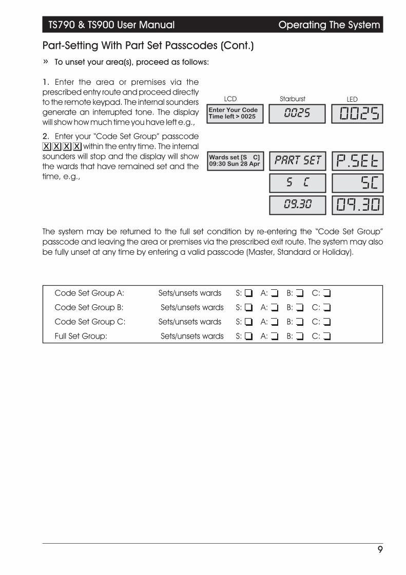
Part-Setting With Part Set Passcodes (Cont.)» To unset your area(s), proceed as follows:
1. Enter the area or premises via theprescribed entry route and proceed directlyto the remote keypad. The internal soundersgenerate an interrupted tone. The displaywill show how much time you have left e.g.,
2. Enter your “Code Set Group” passcodeX X X X within the entry time. The internalsounders will stop and the display will showthe wards that have remained set and thetime, e.g.,
The system may be returned to the full set condition by re-entering the “Code Set Group”passcode and leaving the area or premises via the prescribed exit route. The system may alsobe fully unset at any time by entering a valid passcode (Master, Standard or Holiday).
Code Set Group A: Sets/unsets wards S:o A:o B:o C:o
Code Set Group B: Sets/unsets wards S:o A:o B:o C:o
Code Set Group C: Sets/unsets wards S:o A:o B:o C:o
Full Set Group: Sets/unsets wards S:o A:o B:o C:o
9
TS790 & TS900 User Manual Operating The System
Wards set [S C]09:30 Sun 28 Apr PART SET P.SET
S C SC
09.30 09.30
Enter Your CodeTime left > 0025 0025 0025

Silent SettingThe alarm system may be full or part-set such that the internal sounders are switched off duringthe exit procedure. However the system will give a short tone at the end of the exit procedure toindicate that the system has successfully set.
» To full set the alarm system silently, proceed as follows:
1. Enter your passcode X X X X. Thedisplay will show:
2. Within 5 seconds press 8. The displaywill show:
3. Leave via the prescribed exit route.
4. The system is full set when the exit timehas expired, on activation of the Final Exitcircuit or by pressing the Exit Terminatorbutton, as appropriate.
» To part-set the alarm system silently, proceed as follows:
1. Enter your passcode X X X X. Thedisplay will show:
2. Within 5 seconds press the requiredpart-set button A, B or C, e.g., press A forpart-set A then press 8. The display willshow:
3. Leave the area or premises via theprescribed exit route.
4. The system is part-set when the exit timehas expired, on activation of the Final Exitcircuit or by pressing the Exit Terminatorbutton, as appropriate.
10
Operating The System TS790 & TS900 User Manual
Press ENT toSelect Functions FUNCTION Func.
Please Exit Now.Time left > 9999 9999 9999
Press ENT toSelect Function FUNCTION Func.
Setting theOffice Area Only P. SET A PS.A

Unsetting After An AlarmIf an alarm has occurred whilst the alarm system is full or part-set, the display will indicate thedetection circuit that was triggered when the system is unset. Once the cause of the alarm hasbeen established the system must be reset (see “Resetting after an alarm”).
1. Enter the premises or area via theprescribed entry route and proceed directlyto the remote keypad. The internal sounderswill generate an interrupted tone. Thedisplay will show how much time you haveleft, e.g.,
2. Enter your passcode X X X X withinthe entry time. The internal sounders will stopand the display will show the detectioncircuit that caused the alarm, e.g.,
3. Refer to “Resetting after an Alarm”
+ If “Circuit Text” has been programmed then the display on the LCD and Starburst remotekeypads will alternate between the “Circuit number” and the “Circuit Text” at step (2).
Resetting After An AlarmThe installation company will have programmed the system to be either “User Reset”, “EngineerReset” or “Remote Reset”, consult your installation company if you are not sure.
User ResetFrom step (3) of “Unsetting After An Alarm” proceed follows:
1. Enter your passcode X X X X. Thedisplay will show:
2. Within 5 seconds press ]. The displaywill show:
3. After 5 seconds the “SYSTEM OPEN”message will disappear and the display willshow the time, (date and banner text, LCDonly) e.g.,
Your alarm system is reset by: User:o Engineer:o Remote Reset:o
(Continued Over)
11
TS790 & TS900 User Manual Operating The System
ALARM 0309:45.59 28/04 ALARM 03 CA.03
Enter Your CodeTime left > 0025 0025 0025
Office Detector09:45.59 28/04 OFFICE
Press ENT toSelect Functions FUNCTION Func.
SYSTEM OPEN08:30 Sun 28 Apr OPEN OPEN
ABC Security08:30 Sun 28 Apr 08.30 08.30

Engineer ResetFrom step (3) of “Unsetting After An Alarm” proceed as follows:
1. The display will cycle between thedetection circuit that caused the alarm andthe “CALL ENGINEER TO RESET SYSTEM”. Thesystem will also “beep” every minute toindicate the system requires an engineer toreset the system. To silence the “beeps”simply enter your passcode X X X X.
2. Call the installation company to attendand reset your system.
Tel No._____________________________
+ The display shown at step 2 is programmable and may show something different.
Remote ResetFrom step (3) of “Unsetting After An Alarm” proceed as follows:
1. Follow Step (1) of the “Engineer Reset”procedure.
2. Enter your passcode X X X X. Thedisplay will show:
3. Within 5 seconds press [. “User Menu 1"is selected, the display will show:
4. Press 3 to select the Remote Resetoption. The display will show a random fourdigit “Seed Code” e.g.,
5. Write down the “Seed Code”. Telephoneyour central station and quote the “SeedCode”. You will be asked to report thecircumstances of the alarm. If an engineeris not required to attend site you will begiven a unique four digit “Remote Reset”code.
Tel No._____________________________
6. Enter the four digit “Remote Reset” codeX X X X then press [. A muti-tone beepwill confirm acceptance and the display willreturn to “User Menu 1":
7. Press ] to return to the Unset condition,the display will show:
8. After 5 seconds the “SYSTEM OPEN” message willdisappear and the display will show the time, (dateand banner text, LCD only) e.g.,
12
Operating The System TS790 & TS900 User Manual
ALARM 0309:45.55 28/04 ALARM 03 CA.03Office Detector09:45.55 28/04 OFFICE
CALLENGINEERTORESET SYSTEM CALL CALL
ENGINEER ENG.
Press ENT toSelect Functions FUNCTION Func.
User menu 1Select Option :- USER 1 - 1-Remote ResetQuote > 6846 6846 6846
User menu 1Select Option :- USER 1 - 1-
SYSTEM OPEN08:30 Sun 28 Apr OPEN OPEN
ABC Security08:30 Sun 28 Apr 08.30 08.30
Remote ResetReply > - - - - ---- ----
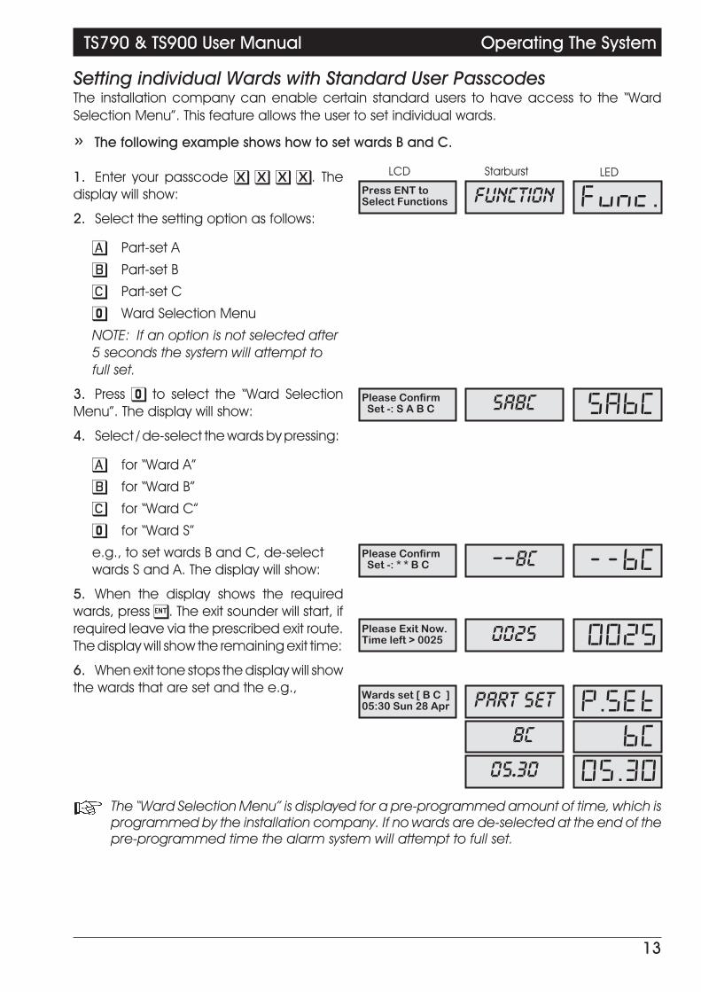
Setting individual Wards with Standard User PasscodesThe installation company can enable certain standard users to have access to the “WardSelection Menu”. This feature allows the user to set individual wards.
» The following example shows how to set wards B and C.
1. Enter your passcode X X X X. Thedisplay will show:
2. Select the setting option as follows:
A Part-set A
B Part-set B
C Part-set C
0 Ward Selection Menu
NOTE: If an option is not selected after5 seconds the system will attempt tofull set.
3. Press 0 to select the “Ward SelectionMenu”. The display will show:
4. Select / de-select the wards by pressing:
A for “Ward A”
B for “Ward B”
C for “Ward C”
0 for “Ward S”
e.g., to set wards B and C, de-selectwards S and A. The display will show:
5. When the display shows the requiredwards, press [. The exit sounder will start, ifrequired leave via the prescribed exit route.The display will show the remaining exit time:
6. When exit tone stops the display will showthe wards that are set and the e.g.,
+ The “Ward Selection Menu” is displayed for a pre-programmed amount of time, which isprogrammed by the installation company. If no wards are de-selected at the end of thepre-programmed time the alarm system will attempt to full set.
13
TS790 & TS900 User Manual Operating The System
Press ENT toSelect Functions FUNCTION Func.
Please ConfirmSet -: S A B C SABC SABC
Please ConfirmSet -: * * B C --BC --BC
Please Exit Now.Time left > 0025 0025 0025
Wards set [ B C ]05:30 Sun 28 Apr PART SET P.SET
BC BC
05.30 05.30

Unsetting individual Wards with Standard User PasscodesIf the installation company has configured the alarm system as described on the previous pagethe standard and master users will be given access to the “Ward Selection Menu” whenunsetting the alarm system.
» The following example shows how to unset wards A and B.
1. Enter the premises via the prescribedentry route and proceed directly to theremote keypad. The internal soundersgenerate an interrupted tone. The displaywill show the remaining entry time:
2. Enter your passcode X X X X beforethe entry timer expires. The display will show:
3. De-select the wards by pressing:
A for “Ward A”
B for “Ward B”
C for “Ward C”
0 for “Ward S”
e.g., to unset wards A and B, de-selectwards S and C. The display will show:
4. When the display shows the requiredwards, press [. The entry sounder will stopand the display will show the wards that areset:
» To unset further wards (assuming wards S and C are set)
1. To unset another ward enter yourpasscode X X X X. The display will show:
2. Select the ward(s) you require to unset,e.g., to unset ward C, de-select ward S. Thedisplay will show:
3. When the display shows the requiredward(s) press [. The display will show thewards that are set:
14
Operating The System TS790 & TS900 User Manual
Please ConfirmUnset -: S A B C SABC SABC
Please ConfirmUnset -: * A B * -AB- -AB-
Wards se t[S C]05:40 Sun 28 Apr PART SET P.SET
S--C S--C
05.40 05.40
Please ConfirmUnset -: S * * C S--C S--C
Please ConfirmUnset -: S * * * S--- S---
Wards set [S ]05:50 Sun 28 Apr PART SET P.SET
S S
05.50 05.50
Enter Your CodeTime left > 0025 0025 0025

» To Set further Wards (assuming ward S is set)
1. To set other wards enter your passcodeX X X X. The display will show:
2. De-select all wards so that the displayshows:
3. Press [ and the display will show:
NOTE: Ward A is not displayed as it isalready set.
4. Select the ward(s) you require to set,e.g., to set wards B and C, press 0 tode-select ward S. The display will show:
5. When the display shows the requiredwards, press [. The exit sounder will start, ifrequired leave via the prescribed exit route.The display will show the remaining exit time:
6. When the system has set the display willshow the wards that are set and the time:
+ If the system is part-set, entry of a valid passcode is assumed to unset rather than setfurther wards. To set further wards, it is necessary to unset nothing, the system will thenassume that you require to set further wards.
15
TS790 & TS900 User Manual Operating The System
Please ConfirmUnset -: S * * * S--- S---
Please ConfirmUnset -: * * * * ---- ----
Please ConfirmSet -: S * B C S-BC S-BC
Please ConfirmSet -: * * B C --BC --BC
Please Exit Now.Time left > 0025 0025 0025
Wards set [ ABC]06:00 Sun 28 Apr PART SET P.SET
ABC ABC
06.00 06.00

Setting & Unsetting Wards with the Code Set Group PasscodesIf the installation company has enabled the "Ward Selection Menu" for your alarm system, allusers defined as "Code Set Group" users will also have access to the "Ward Selection Menu".However the users can only select or de-select the wards that have been assigned to their"Code Set Group", e.g., if "Code Set Group A" is configured to have access to wards A and B,then when the "Ward Selection Menu" is displayed the user can only select or de-select wards Aand B.
The following example uses "Code Set Group A" which is configured to have access to wards Aand B.
» Setting ward B with "Code Set Group A" passcode (system initially unset)
1. Enter your passcode X X X X , thedisplay will show:
2. Select the wards you require to set, e.g.,to set ward B, de-select ward A:
3. When the display shows the requiredward(s) press [ . The exit sounder will start, ifrequired leave via the prescribed exit route.The display will show the remaining exit time:
4. When the system has set the display willshow the wards that are set and the time:
» Unsetting ward B with "Code Set Group A" passcode (System initially full set)
1. Enter the premises via the prescribedentry route and proceed directly to theremote keypad. The internal soundersgenerate an interrupted tone. The displaywill show the remaining entry time:
2. Enter your passcode X X X X beforethe entry timer expires. The display will show:
3. Select the wards you require to unset,e.g., to unset ward B, de-select ward A:
4. When the display shows the requiredwards, press [. The entry sounder will stopand the display will show the wards that areset:
16
Operating The System TS790 & TS900 User Manual
Please ConfirmSet -: * A B * -AB- -AB-
Please ConfirmSet -: * * B * --B- --B-
Please Exit Now.Time left > 0025 0025 0025
Wards set [ B ]06:00 Sun 28 Apr PART SET P.SET
B B
06.00 06.00
Please ConfirmUnset -:* A B* -AB- -AB-
Please ConfirmUnset -: * * B * --B- --B-
Wards set [SA C]06:30 Sun 28 Apr PART SET P.SET
SA-C SA-C
06.30 06.30
Enter Your CodeTime left > 0025 0025 0025
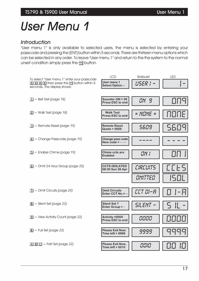
User Menu 1Introduction"User menu 1" is only available to selected users, the menu is selected by entering yourpasscode and pressing the [ENT] button within 5 seconds. There are thirteen menu options whichcan be selected in any order. To leave "User menu 1" and return to the the system to the normalunset condition simply press the ] button.
17
TS790 & TS900 User Manual User Menu 1
User menu 1Select Option :-
To select “User menu 1" enter your passcodeX X X X then press the [ button within 5seconds. The display shows:
USER 1 - 1-
Sounder.ON > 09Press ESC to end
1 = Bell Test (page 18) ON 9 ON9
Walk TestPress ESC to end
2 = Walk Test (page 18) x NONE x NONE
Remote ResetQuote > 5609
3 = Remote Reset (page 19) 5609 5609
Change pass codeNew code > - - - -
4 = Change Passcode (page 19) ---- ----
Chime ccts areEnabled
5 = Enable Chime (page 19) ON 1 ON1
CCTS ISOLATED08:30 Sun 28 Apr
6 = Omit 24 Hour Group (page 20) CIRCUITS CCTS
OMITTED ISOL
Omit CircuitsEnter CCT No.>- -
7 = Omit Circuits (page 20) CCT 01-A 01-A
Silent Set ?Enter Group > -
8 = Silent Set (page 22) SILENT - SIL-
Activity =0000Press ESC to end
9 = View Activity Count (page 22) 0000 0000
Please Exit Now.Time left > 9999
0 = Full Set (page 22) 9999 9999
Please Exit Now.Time left > 0010
A B C = Part Set (page 22) 0010 0010
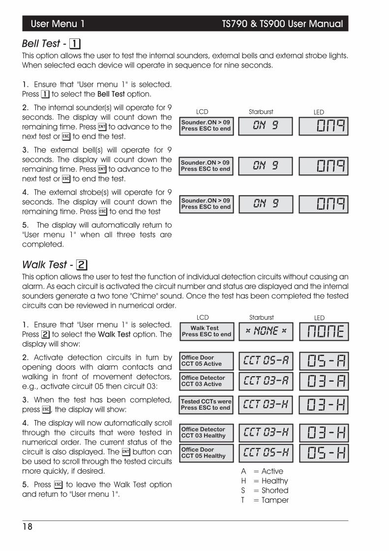
Bell Test - 1This option allows the user to test the internal sounders, external bells and external strobe lights.When selected each device will operate in sequence for nine seconds.
1. Ensure that "User menu 1" is selected.Press 1 to select the Bell Test option.
2. The internal sounder(s) will operate for 9seconds. The display will count down theremaining time. Press [ to advance to thenext test or ] to end the test.
3. The external bell(s) will operate for 9seconds. The display will count down theremaining time. Press [ to advance to thenext test or ] to end the test.
4. The external strobe(s) will operate for 9seconds. The display will count down theremaining time. Press ] to end the test
5. The display will automatically return to"User menu 1" when all three tests arecompleted.
Walk Test - 2This option allows the user to test the function of individual detection circuits without causing analarm. As each circuit is activated the circuit number and status are displayed and the internalsounders generate a two tone "Chime" sound. Once the test has been completed the testedcircuits can be reviewed in numerical order.
1. Ensure that "User menu 1" is selected.Press 2 to select the Walk Test option. Thedisplay will show:
2. Activate detection circuits in turn byopening doors with alarm contacts andwalking in front of movement detectors,e.g., activate circuit 05 then circuit 03:
3. When the test has been completed,press ], the display will show:
4. The display will now automatically scrollthrough the circuits that were tested innumerical order. The current status of thecircuit is also displayed. The [ button canbe used to scroll through the tested circuitsmore quickly, if desired.
5. Press ] to leave the Walk Test optionand return to "User menu 1".
18
User Menu 1 TS790 & TS900 User Manual
Sounder.ON > 09Press ESC to end ON 9 ON9
Sounder.ON > 09Press ESC to end ON 9 ON9
ON 9 ON9Sounder.ON > 09Press ESC to end
Office DoorCCT 05 Active CCT 05-A 05-A
x NONE x NONEWalk TestPress ESC to end
Office DetectorCCT 03 Active CCT 03-A 03-A
Tested CCTs werePress ESC to end CCT 03-H 03-H
Office DetectorCCT 03 Healthy CCT 03-H 03-HOffice DoorCCT 05 Healthy CCT 05-H 05-H
A = ActiveH = HealthyS = ShortedT = Tamper

Remote Reset - 3This option allows the user to Reset the system after an alarm by using a "Remote Reset" code.The full procedure is explained in "Resetting After an Alarm" on page 12.
Change Passcode - 4This option allows all users with access to "User menu 1" to change their own passcode. Themaster user can also add and delete user passcodes, see "Setup Users" on page 25.
1. Ensure that "User menu 1" is selected.Press 4 to select the Change Passcodeoption. The display will show:
2. Enter your new passcode (e.g., 1212)the display will show:
3. Press [ to accept the new passcode, amulti-tone indicates that the new passcodehas been accepted and the display willautomatically return to "User menu 1". A lowtone indicates that the passcode is notavailable. Repeat again from (1) trying adifferent four digit number.
Enable Chime - 5Detection circuits that have been programmed as "Chime" by the installation company or themaster user will generate a two-tone sound if activated. This menu option allows the user toselect one of the five "Chime" options:
Disabled - Detection circuits programmed as “Chime” will NOT generate a“Chime” tone when activated.
Enabled - All detection circuits programmed as “Chime” will generate a “Chime”tone when activated.
Enabled in P.Set - All detection circuits programmed as “Chime” will generate a “Chime”tone when activated during the part-set condition.
Enabled in Unset - All detection circuits programmed as “Chime” will generate a “Chime”tone when activated during the unset condition.
Enabled o/p A On - Ask your installation company for further details on this option.
(continued over)
19
TS790 & TS900 User Manual User Menu 1
Change pass codeNew code > 1212 1212 1212
---- ----Change pass codeNew code > - - - -

1. Ensure that "User menu 1" is selected.Press 5 to select the Enable Chime option.The display will show:
2. Select the chime option by pressing:
0 Enabled/Disabled
1 Disabled (OFF)
2 Enabled (ON 1)
3 Enabled in P.Set (ON 2)
4 Enabled in Unset (ON 3)
5 Enabled o/p A On (ON 4)
B Cycles through options 1 - 5
e.g., to disable the "Chime" featurepress "1", the display will show:
3. When the display shows the requiredsetting press [ to accept. The display willautomatically return to "User menu 1".
Omit 24 Hour Group - 6The installation company or master user may group together detection circuit types 24 Hour andAuxiliary so that they can be omitted when the system is unset. This menu option allows the userto temporarily omit the circuits that have been assigned in the 24 Hour group. This will allow themaccess to areas protected by 24Hr and Auxiliary type detection circuits, e.g., Loading baydoors, Fire Doors, etc.
1. Ensure that "User menu 1" is selected.Press 6 to select the Omit 24 Hour Groupoption. The system remains unset and thedisplay will show:
2. To re-reinstate the 24 hour Group repeatstep (1). The display show the "SYSTEM OPEN"message.
+ If a low tone is generated when this menu option is selected then no detection circuitshave been assigned to the "24 Hour Group"
Omitting Circuits - 7Sometimes it may be necessary to omit detection circuits when setting or part-setting thesystem. This allows the user access to the omitted area(s) when the system is set or part-set. It isalso possible to omit 24hr or Auxiliary circuits so that access to these areas can be obtainedwhen the system is unset. Only detection circuits that have been programmed by theinstallation company as "Omit" may be selected when using this menu option.
When a user unsets the alarm system, either with a passcode or with a keyswitch, the alarmsystem re-instates "Night" detection circuits that were omitted.
20
User Menu 1 TS790 & TS900 User Manual
Chime ccts areDisabled OFF OFF
ON 1 ON1Chime ccts areEnabled
CIRCUITS CCTSCCTS ISOLATED08:30 Sun 28 APR
OMITTED ISOL
OPEN OPENSYSTEM OPEN08:30 Sun 28 APR
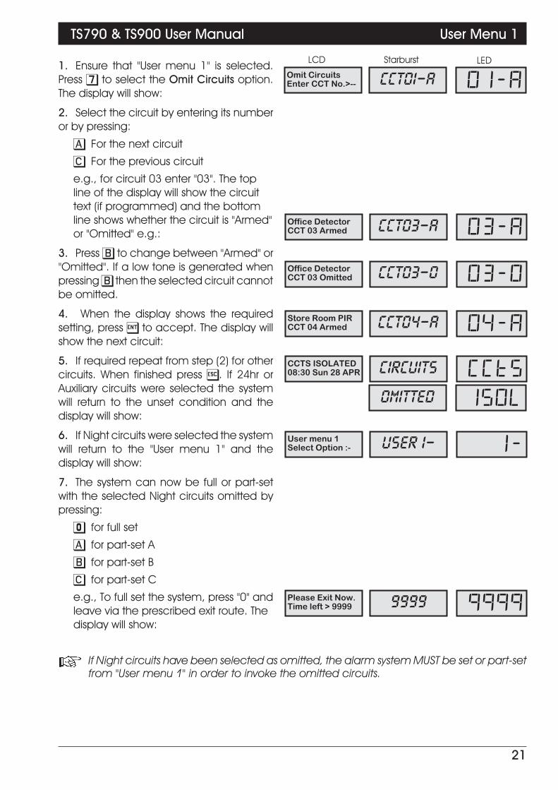
1. Ensure that "User menu 1" is selected.Press 7 to select the Omit Circuits option.The display will show:
2. Select the circuit by entering its numberor by pressing:
A For the next circuit
C For the previous circuit
e.g., for circuit 03 enter "03". The topline of the display will show the circuittext (if programmed) and the bottomline shows whether the circuit is "Armed"or "Omitted" e.g.:
3. Press B to change between "Armed" or"Omitted". If a low tone is generated whenpressing B then the selected circuit cannotbe omitted.
4. When the display shows the requiredsetting, press [ to accept. The display willshow the next circuit:
5. If required repeat from step (2) for othercircuits. When finished press ]. If 24hr orAuxiliary circuits were selected the systemwill return to the unset condition and thedisplay will show:
6. If Night circuits were selected the systemwill return to the "User menu 1" and thedisplay will show:
7. The system can now be full or part-setwith the selected Night circuits omitted bypressing:
0 for full set
A for part-set A
B for part-set B
C for part-set C
e.g., To full set the system, press "0" andleave via the prescribed exit route. Thedisplay will show:
+ If Night circuits have been selected as omitted, the alarm system MUST be set or part-setfrom "User menu 1" in order to invoke the omitted circuits.
21
TS790 & TS900 User Manual User Menu 1
CCT01-A O1-AOmit CircuitsEnter CCT No.>--
CCT03-A O3-AOffice DetectorCCT 03 Armed
CCT03-O O3-OOffice DetectorCCT 03 Omitted
CIRCUITS CCTSCCTS ISOLATED08:30 Sun 28 APR
OMITTED ISOL
USER 1- 1-User menu 1Select Option :-
9999 9999Please Exit Now.Time left > 9999
CCT04-A O4-AStore Room PIRCCT 04 Armed

Silent Set - 8This menu option allows the user to full set or part-set the system silently whilst "User menu 1" isselected. This is an alternative procedure to the one described on page 10.
1. Ensure that "User menu 1" is selected.Press 8 to select the Silent Set option. Thedisplay will show:
2. The system can now be full or part-setsilently by pressing:
0 for full set
A for part-set A
B for part-set B
C for part-set C
e.g., To full set the system, press "0" andleave via the prescribed exit route. Thedisplay will show:
View Activity Count - 9Detection circuits that have been programmed by the installation company as "Flagged" willincrease the activity counter by one each time the circuit is activated when the system is unset.The counter is automatically reset to zero when the system is full or part-set and the counter isre-started when the system is unset. This counter could be used to count the number of personsentering in to a particular area, e.g. shop entrance door. To view the counter proceed asfollows:
1. Ensure that "User menu 1" is selected.Press 9 to select the View Activity Countoption. The display shows the count valuee.g.,
2. Press ] to abandon this option andreturn to "User menu 1".
Full Set and Part-set - 0 A B CThis menu option allows the user to full or part-set the system from "User menu 1" as follows:
1. Ensure that "User menu 1" is selected.The system can now be full or part-set bypressing:
0 for full set
A for part-set A
B for part-set B
C for part-set C
e.g., To full set the system, press "0" andleave via the prescribed exit route. Thedisplay will show:
22
User Menu 1 TS790 & TS900 User Manual
SILENT - SIL-Silent Set ?Enter Group >-
9999 9999Please Exit Now.Time left > 9999
0000 0000Activity = 0000Press ESC to end
9999 9999Please Exit Now.Time left > 9999

User Menu 2IntroductionThis menu is only available to the master user and is selected by pressing the [ button whilst“User menu 1" is selected. There are eleven menu options within this menu, which may beselected in any order. The master user may leave this menu and return to ”User menu 1" bypressing ] button, or advance to “User menu 3" by pressing the [ button.
+ Menu options 6 and 8 are only available if the installation company has programmed themaster users for full access.
23
TS790 & TS900 User Manual User Menu 2
User menu 2Select Option :-
To select “User menu 2" first ensure “User menu1" is selected, then press the [ key. Thedisplay shows: USER 2 - 2-
View CircuitsEnter CCT No.>- -
1 = View Circuits (page 24) CCT 01-H 01-H
Set Clock > - - - -2 = Set the Clock (page 24) ---- ----
Set Date > - - - -3 = Set the Date (page 25) ---- ----
Change passcodeNew code > - - - -
4 = Setup Users (page 25) ---- ----
Alter Chime cctsEnter CCT No.>- -
5 = Alter Chime Circuits (page 28) CCT 01-S 01-S
Alter 24Hr GroupEnter CCT No.>- -
6 = Alter 24Hr Group (page 28) CCT 01-A 01-A
Print System LogNo. events> - - -
7 = Print System Log (page 29) --- ---
Configure WardsEnter CCT No.>- -
8 = Configure Wards (page 30) CCT 01- 01-
PASSCODE 0008:45.59 28/04
9 = View System Log (page 31) USER 00 Ur.00
Remote Call BackEnabled
0 = Remote Call Back (page 33) YES YES
Call Number 10181 12345678
A = Initiate Remote Service Call (page 34) CALL NO.1 No.1
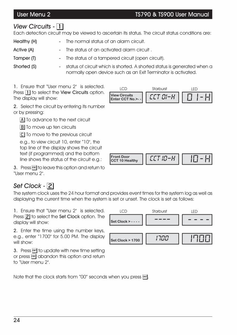
View Circuits - 1Each detection circuit may be viewed to ascertain its status. The circuit status conditions are:
Healthy (H) - The normal status of an alarm circuit.
Active (A) - The status of an activated alarm circuit .
Tamper (T) - The status of a tampered circuit (open circuit).
Shorted (S) - status of circuit which is shorted. A shorted status is generated when anormally open device such as an Exit Terminator is activated.
1. Ensure that “User menu 2" is selected.Press 1 to select the View Circuits option.The display will show:
2. Select the circuit by entering its numberor by pressing:
A To advance to the next circuit
B To move up ten circuits
C To move to the previous circuit
e.g., to view circuit 10, enter “10", thetop line of the display shows the circuittext (if programmed) and the bottomline shows the status of the circuit e.g.:
3. Press ] to leave this option and return to“User menu 2".
Set Clock - 2The system clock uses the 24 hour format and provides event times for the system log as well asdisplaying the current time when the system is set or unset. The clock is set as follows:
1. Ensure that “User menu 2" is selected.Press 2 to select the Set Clock option. Thedisplay will show:
2. Enter the time using the number keys,e.g., enter “1700" for 5.00 PM. The displaywill show:
3. Press [ to update with new time settingor press ] abandon this option and returnto “User menu 2".
Note that the clock starts from “00” seconds when you press [.
24
User Menu 2 TS790 & TS900 User Manual
Front DoorCCT 10 Healthy CCT 10-H 10-H
View CircuitsEnter CCT No.>- - CCT 01-H 01-H
Set Clock > - - - - ---- ----
Set Clock > 1700 1700 1700

Set Date - 3The system date is shown in day/month format, it is used to provide event dates in the system logand is normally displayed (LCD only) when the system is set or unset. The date is set as follows:
1. Ensure that “User menu 2" is selected.Press 3 to select the Set Date option. Thedisplay will show:
2. Enter the date using the number keys,e.g., enter “2804" for 28 April. The display willshow:
3. Press [ and the display will show:
4. Select the day by pressing:
1 for Sunday 5 for Thursday
2 for Monday 6 for Friday
3 for Tuesday 7 for Saturday
4 for Wednesday
e.g., to select Wednesday press 4 thedisplay will show:
5. Press [ to update with new date settingor press ] to abandon this option andreturn to “User menu 2".
Setup Users - 4There are 31 user codes which may be assigned to one of the user types shown below. User 01 isdesignated as the master user and is initially set to 5678. Although user 01 can change theirpasscode the user type cannot be changed. Once the master user has assigned a user to thesystem, they may also change their passcode but they cannot change their user type.Users 2 -31 can be configured as:
Master - If the installation company has programmed the master user for fullaccess, he or she will have access to all user menus and options. If theinstallation company has programmed the master user for limitedaccess, he or she will NOT have access to "User menu 2" options 6 and8, or any of "User menu 3".
Standard - This user type can only access "User menu 1".
Holiday - This user type allows the alarm system to be set and unset, and accessto `User menu 1'. However, the passcode is automatically deletedfrom the system when a master user passcode is used to unset thealarm system. Normally the master user would assign this passcodetype a temporary user whilst the they are away on holiday etc.
25
TS790 & TS900 User Manual User Menu 2
Set Date > 2804 2804 2804
Set Date > - - - - ---- ----
Today is :-Su. . . . . . . . . . . . DAY SUN DAY.1
Today is :-. . . . . .We . . . . . . DAY WED DAY.4

Setup Users (Cont.)Set Only - This user type allows the alarm system to be set and access to "User
menu 1".
Reset Only - This user type allows 24hr alarms to be reset and access to "User menu1" option 1 to 9.
Duress - When a user keys in a duress code the alarm system sends a silent"Panic Alarm" to the central station without triggering Bell or sounders.Note that the system must be fitted with a remote signalling deviceconnected to a telephone line. The user can set and unset the alarmsystem and access "User menu 1" when using the duress code.
Note: All other user code types may generate a "Duress" alarm if thepasscode is entered with the first two digits reversed (e.g., for astandard passcode of 2580 enter 5280 to generate a "Duress" alarm).If required, this feature can be disabled by the installation company orby making the first two digits of the passcode the same.
PA Code - When this user type is entered a "Panic Alarm"' is transmitted to thecentral station via the telephone line and remote signalling device (iffitted). The external sounder(s) and strobe light(s) are also activated.
Access - When a user keys in this type of code the alarm system activates anyoutput programmed as `Access' for a pre-set time. Normally this usertype is used in conjunction with an electric door strike connected to thealarm system. When a user enters the passcode the alarm systemoperates the door strike to allow the user access into that area.
Full Set Group - This user type only allows wards assigned by the installation companyor master user to be set and unset. This user type does not have accessto any user menus.
Code Set Group A - This user type only allows the wards assigned by the installationcompany or master user to be set and unset. This user type does nothave access to any user menus.
Code Set Group B - This user type only allows the wards assigned by the installationcompany or master user to be set and unset. This user type does nothave access to any user menus.
Code Set Group C - This user type only allows the wards assigned by the installationcompany or master user to be set and unset. This user type does nothave access to any user menus.
-Note: For more information for Full Set Groups and Code Set Groups see page 40.
26
User Menu 2 TS790 & TS900 User Manual

Setup Users (Cont.)To setup users proceed as follows:
1. Ensure that “User menu 2" is selected.Press 4 to select the Setup users option. Thedisplay will show:
2. Enter the user number (02-31) requiredto be setup, e.g., to setup user 12 enter "12"followed by [. The display will show thecurrent user type (Note: If the code iscurrently unassigned, the display will show"Not in use":
3. Select a new user type by pressing:
1 for Master 7 for PA Code
2 for Standard 8 for Access
3 for Holiday 9 for Full set group
4 for Set Only A for Code set grp A
5 for Reset Only B for Code set grp B
6 for Duress C for Code set grp C
e.g., to select user type "Standard"press "2". The display will show:
4. When the display shows the requireduser type press [ to accept. The display willshow:
5. Enter a 4 digit passcode for the selecteduser, e.g., enter "2580". The display willshow:
6. Press [ to update with new passcode, amulti-tone will indicate that the passcodehas been accepted and the display willreturn to step 1. A low tone indicates that thepasscode is not available. Re-enter, trying adifferent 4 digit passcode.
7. Repeat from step 1 for other users orpress ] to return to "User menu 2".
+ To delete user passcodes 02-31 from the system, select the user number you wish todelete at step 2, then enter your own passcode at step 5.
27
TS790 & TS900 User Manual User Menu 2
Alter user typeNot in use NOT USED NoTU
Setup usersUser No. > -- USER -- Ur--
Alter user typeStandard STANDARD TYP.2
Change passcode ---- ----
Change passcode 2580 2580

Alter Chime Circuits - 5This menu option allows the master users to select which detection circuits are designated as"Chime". Once programmed as “Chime” all users that have access to "User menu 1" can selectone of the the six "Chime" options. See "Enable Chime" on page 19.
1. Ensure that “User menu 2" is selected.Press 5 to select the Alter Chime Circuitsoption. The display will show:
2. Select the circuit by entering itsnumber or by pressing:
A To advance to the next circuit
C For the previous circuit
3. e.g., for circuit 07 enter “07", the top lineof the display shows the circuit text (ifprogrammed) and the bottom line showswhether the circuit is selected as “Chime” or“Silent” e.g.:
4. Press B to change between “Chime”and “Silent”. If a low tone is generated whenpressing B then the selected circuit cannotbe programmed as “Chime”.
5. Repeat from step 2 for other circuits,when finished press ] to abandon thisoption and return “User menu 2".
Alter 24Hr Group - 6Detection circuits types “24Hr” and “Auxiliary” can be grouped together so that if required theusers can omit the group when the system is unset.
1. Ensure that “User menu 2" is selected.Press 6 to select the Alter 24Hr Groupoption. The display will show:
2. Select the circuit by entering itsnumber or by pressing:
A To advance to the next circuit
C For the previous circuit
e.g., for circuit 10 enter “10", the topline of the display shows the circuit text(if programmed) and the bottom lineshows whether the circuit is selected as“Armed” or “Omitted”, e.g.:
3. Press B to toggle between “Armed” and“Omitted”. If a low tone is generated whenpressing B then the selected circuit cannotbe programmed into the 24Hr group.
28
User Menu 2 TS790 & TS900 User Manual
Entrance DoorCCT 07 Silent CCT 07-S 07-S
Alter Chime cctsEnter CCT No.>- - CCT 01-S 01-S
Entrance DoorCCT 07 Chime CCT 07-C 07-C
Alter 24Hr GroupEnter CCT No.>- - CCT 01-A 01-A
Loading BayDoor CCT 10-A 10-A
Loading BayDoor CCT 10-O 10-O

4. Repeat from step 2 for other circuits,when finished press ] to abandon thisoption and return “User menu 2".
Print System Log -7The system log stores 700 events (1800 when expanded), if a printer is connected to the system itis possible to print a selected number of events. Once the print-out has been started it can onlybe stopped by selecting this option again and entering “000" for the number of events.
1. Ensure that “User menu 2" is selected.Press 7 to select the Print System Logoption. The display will show:
2. Enter the number of events to be printed000-699 (0000-1799 if expanded), e.g.,enter “150" for the last 150 events, startingwith the most recent event. The display willshow:
3. Press [ to start printing, the display willautomatically return to “User menu 2". ToCancel printing repeat from step 1 andselect ”000" (“0000" if expanded) events atstep 2.
+ If the printer is left connected to the system it will print-out system events as and when theyoccur (real time print-out).
29
TS790 & TS900 User Manual User Menu 2
Print System LogNo. events> - - - --- ---
Print System LogNo. events> 150 150 150

Configure Wards - 8The TS790 & TS900 can be split into four wards:
» System Ward (S)
» Ward A
» Ward B
» Ward C
Each ward can be assigned to a passcode or part-set button to allow flexible part-setarrangements. See “Part Set Groups” on page 39 and “Code Set Groups” on page 40.
Only “Night”, “Final Exit” and “Exit terminator” circuit types can be assigned to wards A, B and C.Circuits can be assigned to more than one ward (A, B or C) thus creating overlapping areas.Circuits assigned to more than one ward will only be armed when both or all wards are set.From the factory, all detection circuits are assigned to the system ward (i.e., they are notassigned to wards A, B or C). Circuits that remain assigned to the system ward can also be set orunset independently. See “Part Set Groups” on page 39 and “Code Set Groups” on page 40.
1. Ensure that “User menu 2" is selected.Press 8 to select the Configure Wardsoption. The display will show:
2. Enter the circuit number, e.g., for circuit02 enter “02". The top line of the displayshows the circuit text (if programmed) andthe bottom line shows the wards that thecircuit are assigned to e.g.:
3. Select/de-select the wards by pressing:
A for “Ward A”
B for “Ward B”
C for “Ward C”
e.g., press “A” then “B” to assign circuit02 to wards A and B. If a low tone isgenerated when pressing the “A”, “B” or“C”, then the selected circuit cannotbe programmed into wards.
4. Press [ to accept and repeat from step2 for other circuits, when finished press ] toabandon this option and return “Usermenu 2".
30
User Menu 2 TS790 & TS900 User Manual
Store Room PIRCCT 02 in [AB ] CCT 02-A 02-A
Configure WardsEnter CCT No.>- - CCT 01- 01-
Store Room PIRCCT 02 in [ ] CCT 02- 02-
CCT 02-B 02-B

Viewing the System Log with an LCD Remote Keypad - 9To view the log with an LCD remote keypad, proceed as follows:
1. Ensure that “User menu 2" is selected. Press 9 to selectthe View Log option. The display shows the mostrecent event. The top line shows the event description (seeTable 1), and the bottom line shows the time and the datethat the event occurred on e.g.:
2. Use the A or [ keys to view previous events or the C keyto scroll forwards through the log, e.g., enter A to scrollbackwards. The display shows the previous event e.g.:
3. If the event being displayed is one that refers to a usernumber, e.g.,"PASSCODE 01". Pressing the B key will togglebetween the user text (name) and user number for thatevent.
4. If the event being displayed is one that refers to a circuitnumber, e.g., “ALARM 02". Pressing the B key will togglebetween the circuit number and circuit text for that event.
5. Press ] to leave this option and return to “User menu 2".
Viewing The Log With an LED or Starburst Remote Keypad -9To view the log with an LED or Starburst remote keypad, proceed as follows:
1. Ensure that “User menu 2" is selected. Press 9 to selectthe View Log option. The display will show the most recentevent (see Table 1), e.g.:
2. Use the A or [ keys to view previous events or the C keyto scroll forwards through the log, e.g., enter “A” to scrollbackwards. The display shows the previous event e.g.:
3. To view the time for the selected event press B once.The display shows the time that the event occurred, e.g.,“08.40 am”:
4. To view the date for the selected event press B again.The display shows the date that the event occurred, e.g.,“28 April”:
5. To view the minutes and seconds for the selected eventpress B again. The display shows the minutes and secondsthat the event occurred, e.g., “40 mins & 59 secs”:
6. To view the event description again for the selectedevent press B again. The display shows the eventdescription again, e.g.,:
7. Press ] to leave this option and return to “User menu 2".
31
TS790 & TS900 User Manual User Menu 2
PASSCODE 0108:45.59 28/04
PASSCODE 0108:40.59 28/04
PASSCODE Colin08:40.59 28/04
PASSCODE 0108:40.59 28/04
ALARM 0206:00.59 28/04
Store Room PIR06:00.59 28/04
USER 01 Ur.01
USER 01 Ur.01
08.40 08.40
2804 2804
4059 4059
USER 01 Ur.01

LCD Starburst LED Description
ACTION ALARM ALM SENT AA Alarm activated when system is part-set.
AC OFF A.C. OFF PF Mains power removed.
AC RESTORED A.C. ON Pr Mains power restored
ACCESS 01-31 ACC'SS 01-31 Ac.01-31 Access user passcode (01-31) entered.
ALARM 01-56 ALARM 01-56 CA.01-56 Full alarm from circuit (01-56).
AUX/BELL TAMPER AUX TAMP AT Auxiliary tamper activated.
AUXILIARY 01-56 AUX 01-56 Au.01-56 Auxiliary circuit activated.
BATTERY FAULT BATT FLT BF Battery fault (voltage below 10.5V).
BELL TESTED BELL TST BT External bell and strobes tested.
CALL BACK No. 01-03 C. BACK 01-03 CB.01-03 Modem making a call back to remote PC.
CCTS ISOLATED 24HR OM'T CI 24Hr group omitted during the unset condition.
CCT OMITTED OMIT'D 01-56 CO.01-56 Circuits omitted by the user at time of Setting.
CIRCUITS TESTED 01-56 TEST'D 01-56 Tc.01-56 The number of circuits tested during Walk Test.
CODE TAMPER C.TMP 01-04 PT.01-04 Code tamper from keypad 01-04
COMMS ACTIVE COM ACT cA Plug-on digicom active.
COMMS FAILED COMS FLT cF Plug-on digicom failed to communicate.
COMMS SUCCESSFUL COMS OK cc Plug-on digicom communicated successfully.
DATE CHANGED DATE CHG Dc System Date changed.
DEFAULT CODE DEFLT 01 DF User passcode (01) reset to 5678 by the engineer.
DELAY ALARM 01-56 DELAY 01-56 AD.01-56 Delayed alarm during a part-set condition.
DURESS 01-31 DUR'SS 01-31 Du.01-31 Duress alarm from user passcode (01-31).
ENTRY 01-56 ENTRY 01-56 En.01-56 Entry timer started by circuit (01-56).
ENTRY ALARM 01-56 EN.ALM 01-56 EA.01-56 Entry timed-out alarm from circuit (01-56).
FACTORY RESTART FACT. RST Fr System “Factory Restarted”.
FIRE ALARM 01-56 FIRE 01-56 FA.01-56 Fire alarm circuit activated.
FIRST KNOCK 01-56 FIRST 01-56 Fn.01-56 The first activation of a Double Knock circuit.
FUSE BLOWN 01 FUSE 01 FB.01 Control Panel 12V Auxiliary Fuse blown.
INACTIVE CCTS 01-56 INACT 01-56 IA.01-56 Inactive circuits during the Unset condition.
KEY POINT 01-56 KEY.SW 01-56 So.01-56 Key point operation from circuit (01-56).
LINE FAULT LINE FLT LF Telephone line fault detected.
LINE RESTORED LINE OK Lr Telephone line fault restored.
MODEM LOCK-OUT LOCK-OUT LO Modem failed to communicate.
NO EVENT NO EVENT -- No log event.
NODE ADDED 01-05 N.ADD 01-05 NA.01-05 Node added to the system.
NODE FUSE 01-05 N.FUSE 01-05 NF.01-05 Node fuse blown.
NODE REMOVED 01-05 N.REM 01-05 Nr.01-05 Node removed from the system.
NODE TAMPER 01-05 N.TMP 01-05 NT.01-05 Node cover removed.
ON-SITE RESTART SITE. RST Sr System “On-Site” restart.
OMITS REMOVED OMIT REM Or Previously omitted circuits reinstated.
Table 1a Log event codes and descriptions
32
User Menu 2 TS790 & TS900 User Manual

LCD Starburst LED Description
PA ALARM 01-56 PA.ALM 01-56 PA.01-56 Panic Alarm circuit activated.
PA CODE 01-31 PANIC 01-56 PC.01-31 Panic Alarm passcode entered.
PANEL LID TAMPER LID TAMP LT Control panel lid removed.
PART SET A/B/C P.SET A/B/C PS.A/B/C System Part-Set using one of the A, B, or C buttons.
PASSCODE 00-31 USER 00-31 Ur.00-31 User passcode entered. (00-31).
REMOTE ADDED 01-04 R. ADD 01-04 RA.01-04 Remote Keypad added to the system.
REMOTE RESET REM RST rc System reset by “Remote Reset” passcode.
REM REMOVED 01-04 R. REM 01-04 rr.01-04 Remote Keypad removed from system.
REM SERVICE CALL R.S. CALL SC Remote service call via “Lineload” software and PC.
REM TAMPER 01-04 R. TMP 01-04 rT.01-04 Remote Keypad cover removed.
SERVICE CALL END R.S. END SE Remote service call finished.
SERVICE REQUIRED SERVICE rS Service required
SET FAIL SET FAIL SF System failed to Set.
SET WARD A/B/C/S W. SET A/B/C/S ST.ABCS Wards A, B, C or System Set.
SYSTEM OPEN SYS OPEN OP System fully unset.
SYSTEM RE-ARMED RE-ARMED rA System re-armed all healthy circuits.
SYSTEM SET FULL SET FS System fully set.
TAMPER 01-56 TAMP'R 01-56 TA.01-56 Tamper alarm from circuit.
TEST CCTS OFF TEST OFF To All circuits taken off “Test”
TEST FAIL 01-56 T. FAIL 01-56 TF.01-56 Circuit failed during “Test”.
TIME CHANGED TIME CHG Tc System time changed
UNSET WARD A/B/C/S UNSET A/B/C/S Un.ABCS Wards A, B, C or System Unset.
WALK TEST WALK TST cT System “Walk Test” selected.
Table 1b Log event codes and descriptions
Remote Call Back - 0If your alarm system is fitted with a modem, the installation company can dial into the systemand remotely access data from the control panel. For added security the installation companycan also program your alarm system so that a master user has to authorise any writecommands. When "Remote Call Back" is set to "Enabled" the installation company can dial intothe system at any time and read and write data from the control panel. When "Remote CallBack" is set to "Disabled" the installation company can dial into the system at any time and onlyread data from the control panel. Once a master user has enabled "Remote Call Back" thesystem will automatically disable "Remote Call Back" after four hours.
1. Ensure that “User menu 2" is selected.Press 0 to select the Remote Call Backoption. The display will show:
2. Press B to toggle between Enabled(Yes) and Disabled (No). Press [ to updatewith new setting or press ] abandon thisoption and return to “User menu 2".
33
TS790 & TS900 User Manual User Menu 2
Remote Call BackEnabled YES YES

Initiate Remote Service Call -AIf your alarm system is fitted with a modem, it is possible for a master user to initiate an uploadsequence to a remote site (normally the alarm company or central station). Once thecommunication link is established, the remote site can read and write data from the controlpanel. This feature is only compatible with Menvier Lineload software version 2.0 or above.
+ Only select this option when requested by the installation company, if this option isselected without authorisation from the installation company the modem may notconnect with the remote site.
To initiate a Remote Service Call, proceed as follows:
1. Ensure that “User menu 2" is selected.Press A to select the Initiate RemoteService Call option. The display will show:
2. Select the telephone number yourequire to call, by pressing:
1 to call number 1
2 to call number 2
3 to call number 3
e.g., to select remote site 2 press 2.The display will show:
Note: Ask your alarm installer whichnumber is the best one to use.
3. Press [ to initiate the upload sequenceto the remote site or press ] to abandonthis option.
34
User Menu 2 TS790 & TS900 User Manual
CALL NO.1 No.1
Call Number 20181 12345679 CALL NO.2 No.2
Call Number 10181 12345678
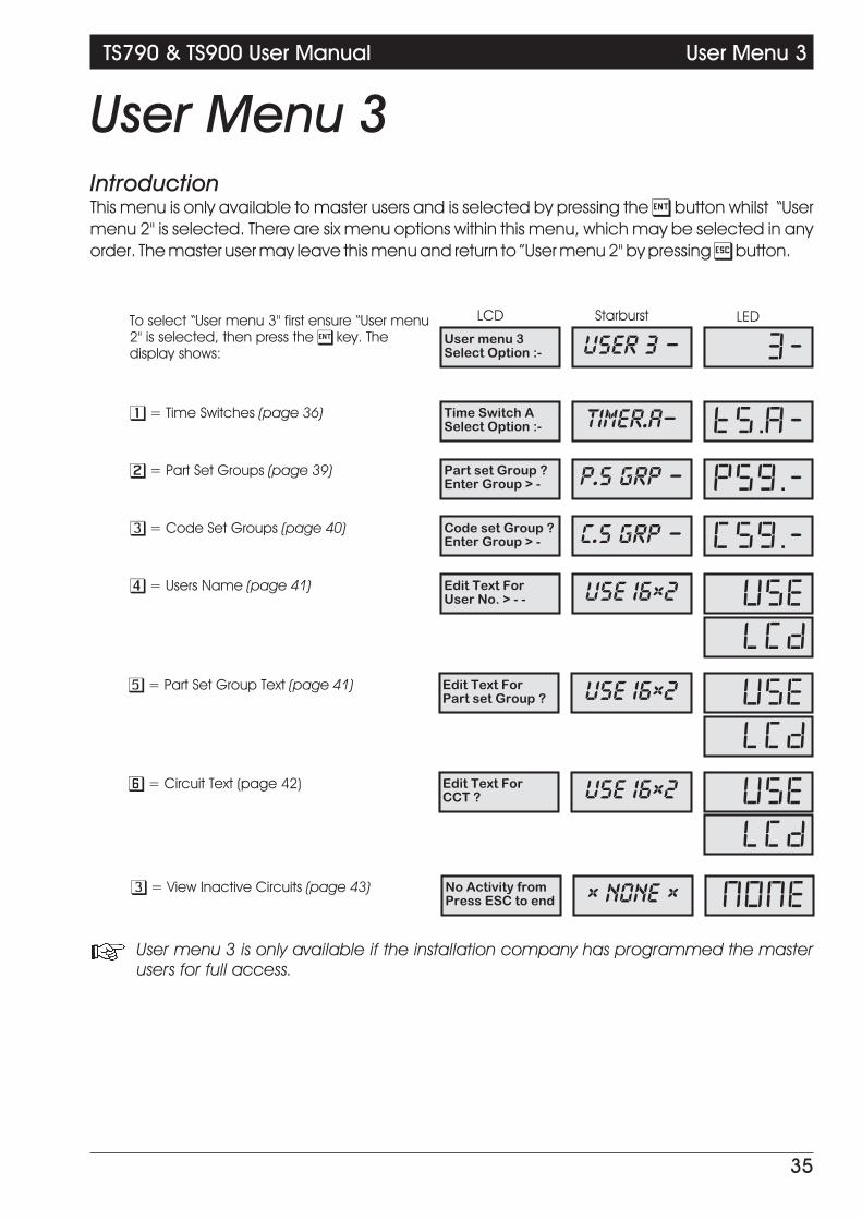
User Menu 3IntroductionThis menu is only available to master users and is selected by pressing the [ button whilst “Usermenu 2" is selected. There are six menu options within this menu, which may be selected in anyorder. The master user may leave this menu and return to ”User menu 2" by pressing ] button.
+ User menu 3 is only available if the installation company has programmed the masterusers for full access.
35
TS790 & TS900 User Manual User Menu 3
User menu 3Select Option :-
To select “User menu 3" first ensure “User menu2" is selected, then press the [ key. Thedisplay shows: USER 3 - 3-
Time Switch ASelect Option :-
1 = Time Switches (page 36) TIMER.A- TS.A-
Part set Group ?Enter Group > -
2 = Part Set Groups (page 39) P.S GRP - PSG.-
Code set Group ?Enter Group > -
3 = Code Set Groups (page 40) C.S GRP - CSG.-
Edit Text ForUser No. > - -
4 = Users Name (page 41)
Edit Text ForPart set Group ?
5 = Part Set Group Text (page 41)
Edit Text ForCCT ?
6 = Circuit Text (page 42)
USE 16x2 USE
LCD
USE 16x2 USE
LCD
USE 16x2 USE
LCD
No Activity fromPress ESC to end
3 = View Inactive Circuits (page 43) x NONE x NONE
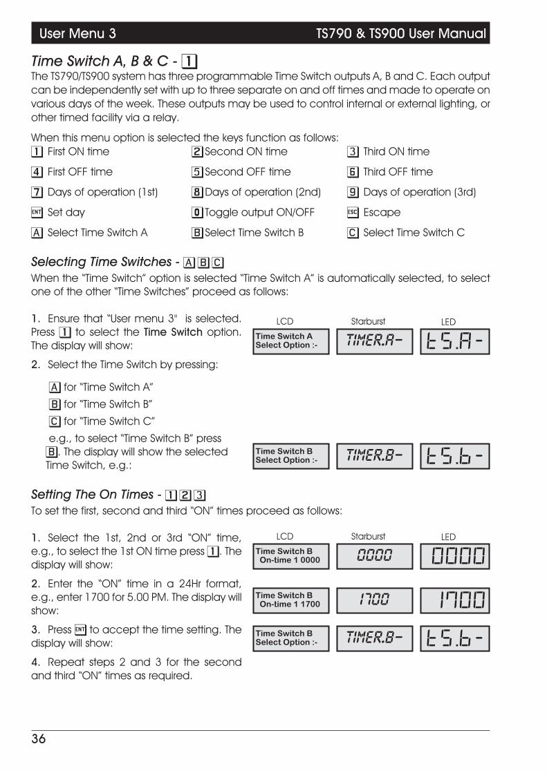
Time Switch A, B & C - 1The TS790/TS900 system has three programmable Time Switch outputs A, B and C. Each outputcan be independently set with up to three separate on and off times and made to operate onvarious days of the week. These outputs may be used to control internal or external lighting, orother timed facility via a relay.
When this menu option is selected the keys function as follows:1 First ON time 2 Second ON time 3 Third ON time
4 First OFF time 5 Second OFF time 6 Third OFF time
7 Days of operation (1st) 8 Days of operation (2nd) 9 Days of operation (3rd)
[ Set day 0 Toggle output ON/OFF ] Escape
A Select Time Switch A B Select Time Switch B C Select Time Switch C
A B C
When the “Time Switch” option is selected “Time Switch A” is automatically selected, to selectone of the other “Time Switches” proceed as follows:
1. Ensure that “User menu 3" is selected.Press 1 to select the Time Switch option.The display will show:
2. Select the Time Switch by pressing:
A for “Time Switch A”
B for “Time Switch B”
C for “Time Switch C”
e.g., to select “Time Switch B” pressB. The display will show the selectedTime Switch, e.g.:
Setting The On Times - 1 2 3
To set the first, second and third “ON” times proceed as follows:
1. Select the 1st, 2nd or 3rd “ON” time,e.g., to select the 1st ON time press 1. Thedisplay will show:
2. Enter the “ON” time in a 24Hr format,e.g., enter 1700 for 5.00 PM. The display willshow:
3. Press [ to accept the time setting. Thedisplay will show:
4. Repeat steps 2 and 3 for the secondand third “ON” times as required.
36
User Menu 3 TS790 & TS900 User Manual
Time Switch ASelect Option :- TIMER.A- TS.A-
Time Switch BSelect Option :- TIMER.B- TS.B-
Time Switch BOn-time 1 0000 0000 0000
Time Switch BOn-time 1 1700 1700 1700
Time Switch BSelect Option :- TIMER.B- TS.B-

Setting The Off Times - 4 5 6
To set the first, second and third Off times proceed as follows:
1. Ensure that the required Time Switch isselected, e.g., Time Switch B. The display willshow:
2. Select the first, second or third “OFF”times by pressing:
4 for the first OFF time
5 for the second OFF time
6 for the third OFF time
e.g., to select the first “OFF” time press“4". The display will show:
3. Enter the “OFF” time in a 24Hr format,e.g., for 6.00 PM enter “1800". The displaywill show:
4. Press [ to accept the time setting. Thedisplay will show:
5. Repeat steps 2, 3 and 4 for the secondand third “OFF” times as required.
Setting The Days Of Operation -7 8 9
To set the days that the first, second and third On and Off times operate on, proceed as follows:
1. Ensure that the required Time Switch isselected, e.g., Time Switch B. The display willshow:
2. Select the days of operation for the first,second or third timer by pressing:
7 for the first timer
8 for the second timer
9 for the third timer
e.g., press 7 to set the days ofoperation for the first ON/OFF timer. Thedisplay will show:
3. Select/de-select the days of operationusing keys 1 to 7, e.g., press 1 then 2 toselect the days Sunday & Monday etc. Thedisplay will show:
4. Press [ to accept the days of operationsetting. The display will show:
5. Repeat steps 2, 3 and 4 for the secondand third ON/OFF times as required.
37
TS790 & TS900 User Manual User Menu 3
Time Switch BSelect Option :- TIMER.B- TS.B-
Time Switch BOff-time 1 0000 0000 0000
Time Switch BOff-time 1 1800 1800 1800
Time Switch BSelect Option :- TIMER.B- TS.B-
Time Switch BSelect Option :- TIMER.B- TS.B-
Operates on :-. . . . . . . . . . . . . . . DAY DAY.
Operates on :- DAY SUN DAY.1
Time Switch BSelect Option :- TIMER.B- TS.B-
DAY MON DAY.2

Setting The Day -[
For the Time Switches to operate on the correct days the system requires the current day to beentered. This will also be displayed on the bottom line of LCD remote keypads. Set the day asfollows:
1. Ensure that the required Time Switch isselected, e.g., Time Switch B. The display willshow:
2. Press [ to set the day. The display willshow:
3. Select the day by using keys 1 to 7, e.g.,press 4 to select the day Wednesday. Thedisplay will show:
4. Press [ to accept the setting, thedisplay will show:
Manually Switching The Output -0
The Time Switch output may be manually switched On and Off as follows:
1. Ensure that the required Time Switch isselected, e.g., Time Switch B. The display willshow:
2. Press the 0 key. The display will show thestatus of the selected Time Switch e.g.,
3. Press the 0 key to toggle the selectedTime Switch output “ON” and “OFF”, e.g. toswitch output on press “0". The display willshow:
4. Press ] to return to step 1 and, ifrequired, press ] again to return to “Usermenu 3”.
38
User Menu 3 TS790 & TS900 User Manual
Today is :-Su. . . . . . . . . . . . DAY SUN DAY.1
Time Switch BSelect Option :- TIMER.B- TS.B-
Time Switch BSelect Option :- TIMER.B- TS.B-
Today is :-. . . . . .We . . . . . . DAY WED DAY.4
Time Switch Bis OFF OFF OFF
Time Switch BSelect Option :- TIMER.B- TS.B-
Time Switch BSelect Option :- TIMER.B- TS.B-
Time Switch Bis ON ON ON

Part Set Groups - 2This option allows the “Part-Set buttons” A, B and C to be defined so that they can set anycombination of wards (S, A, B and C), e.g., “Button A” can be defined to set wards A and B, and“Button B” defined to set only ward B. Each “Part set Group” may also have up to 32 characters oftext assigned. See Edit Text For Part Set Groups on page 41.The following example shows how to define “Part set Group A” (Button A), so that wards S,A & Care set when the button is selected by the user at time of setting:
1. Ensure that “User menu 3" is selected.Press 2 to select the Part set Groups option.The display will show:
2. Select the “Part set group” by pressing:
A for “Part set Group A”
B for “Part set Group B”
C for “Part set Group C”
e.g., To select “Part set Group A”, pressA. The display will show:
3. Select/de-select the wards that will setwhen the “Part set group” is selected, bypressing:
0 To select/de-select “Ward S”
A To select/de-select “Ward A”
B To select/de-select “Ward B”
C To select/de-select “Ward C”
e.g., To select “Ward S” and “Ward C”.Press 0, then C. The display will show:
4. When the display shows the requiredsetting press [ to accept. The display willreturn to step 1. Repeat for other part setgroups (B or C) or press ] to return to “Usermenu 3".
Part Set Group OperationWhen a “Master” or “Standard” user passcode is entered during the unset mode the alarmsystem will attempt to fully set after a five second delay. However, if during the five second delayone of the part-set buttons A, B or C is pressed, the display will show relevant “Part-set Text” andafter a short delay the system will only set the areas (wards) that are assigned to the selected“Part set Group”.
39
TS790 & TS900 User Manual User Menu 3
Part set Group ?Enter Group >- P.S GRP- PSG.-
Part set Group AWill set [ A ] A A
Part set Group AWill set [SA C] SA C SAC

Code Set Groups - 3This option allows the user passcode types “Code Set Group A”, “Code Set Group B”, “Code SetGroup C” and “Full Set Group” to be defined so that each may Set or Unset any combination ofWards (A, B and C) and the System Ward. e.g., “Code Set Group A” may be defined to Set andUnset Wards A and B only and “Code Set Group B” defined to Set and Unset Wards B, C and thesystem etc.
1. Ensure that “User menu 3" is selected.Press 3 to select the Code Set Groupsoption. The display will show:
2. Select the Code set group by pressing:
A To select “Code set Group A”
B To select “Code set Group B”
C To select “Code set Group C”
0 To select “Full set Group”
e.g., To select “Code set Group A”,press A. The display will show:
3. Select/de-select the wards by pressing:
0 To select/de-select “Ward S”
A To select/de-select “Ward A”
B To select/de-select “Ward B”
C To select/de-select “Ward C”
e.g., to add “Ward C”, press C. Thedisplay will show:
4. When the display shows the requiredsetting press [ to accept. The display willreturn to step 1, repeat for the other “Codeset Groups” or press ] to return to “Usermenu 3".
Code Set Group OperationWhen the system is unset and a “Code set Group” passcode is entered the selected areas(wards) will set after the setting procedure is followed. e.g., If “Code set Group A” is defined asabove then when the passcode is entered it will set wards A and C. If the system is fully set andthe passcode is entered it will unset wards A and C.
The “Code set Group” passcodes are programmed by the master user within “User menu 2" (seepage 25).
40
User Menu 3 TS790 & TS900 User Manual
Code set Group ?Enter Group >- C.S GRP- CSG.-
Code set Group AWill set [ A ] A A
Code set Group AWill set [ A C] A C AC

User Names (NETLCD Remote Keypads Only) -4This option allows the master user to assign up to seven characters of text against each userpasscode. When viewing the log, users that have a name programmed appear in the eventdescription, e.g., "PASSCODE Fred". If the user name is left blank the event description will showthe user number, e.g., ”PASSCODE 01".
When this menu option is selected the keypad operates in a text mode, see page 44 for fulldetails.To program the user names proceed as follows:
1. Ensure that “User menu 3" is selected. Press 4 to selectthe User Name option. The display will show:
2. Enter the user number 01-31, e.g., enter "01" for user 01,then press [ . The display will show:
3. Use the keypad keys to program text (see page 44).When the display shows the required text press [ to acceptor press ] to abandon and return to step 1. Repeat for theother “User Names” or press ] to return to “User menu 3".
Edit Text For Part Set Groups (TS900 Remote Keypads Only) -5When the system is being part-set using the part-set button A, B or C the display will show thedefault message of “Part set group A (B or C)”. This message can be changed using up to 32characters, e.g., “Part set group A” may be changed to “Setting Office area only”.
When this menu option is selected the keypad operates in a text mode, see page 44.To program the part-set text name proceed as follows:
1. Ensure that “User menu 3" is selected. Press 5 to selectthe Edit Text for Part Set Groups option. The display will show:
2. Select the “Part set Group” by pressing:
A for “Part set Group A”
B for “Part set Group B”
C for “Part set Group C”
e.g., to select “Part set Group A” pressA. The display will show:
3. Use the keypad keys to program text (see page 44).When the display shows the required text press [ to accept.The display will return to step 1. Repeat for the other “Part setGroups” or press ] to return to “User menu 3".
41
TS790 & TS900 User Manual User Menu 3
Edit Text ForUser No. > - -
->User 01^
Edit Text ForPart set Group ?
^art set Group A
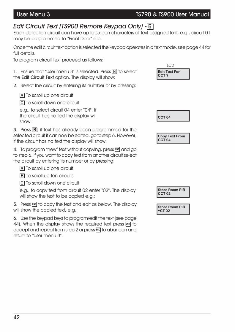
Edit Circuit Text (TS900 Remote Keypad Only) -6Each detection circuit can have up to sixteen characters of text assigned to it, e.g., circuit 01may be programmed to “Front Door” etc.
Once the edit circuit text option is selected the keypad operates in a text mode, see page 44 forfull details.To program circuit text proceed as follows:
1. Ensure that “User menu 3" is selected. Press 6 to selectthe Edit Circuit Text option. The display will show:
2. Select the circuit by entering its number or by pressing:
A To scroll up one circuit
C To scroll down one circuit
e.g., to select circuit 04 enter “04". Ifthe circuit has no text the display willshow:
3. Press B, if text has already been programmed for theselected circuit it can now be edited, go to step 6. However,if the circuit has no text the display will show:
4. To program “new” text without copying, press [ and goto step 6. If you want to copy text from another circuit selectthe circuit by entering its number or by pressing:
A To scroll up one circuit
B To scroll up ten circuits
C To scroll down one circuit
e.g., to copy text from circuit 02 enter “02". The displaywill show the text to be copied e.g.:
5. Press [ to copy the text and edit as below. The displaywill show the copied text, e.g.:
6. Use the keypad keys to program/edit the text (see page44). When the display shows the required text press [ toaccept and repeat from step 2 or press ] to abandon andreturn to “User menu 3".
42
User Menu 3 TS790 & TS900 User Manual
Edit Text ForCCT ?
CCT 04
Copy Text FromCCT 04
Store Room PIRCCT 02
Store Room PIR^CT 02
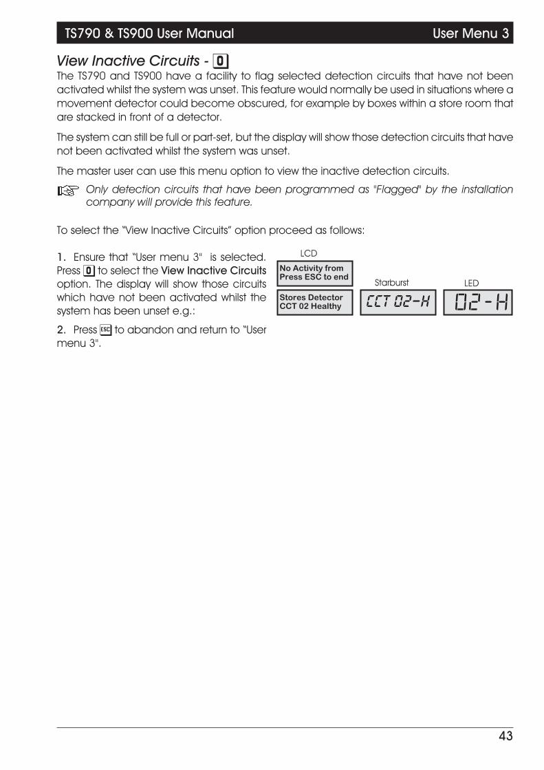
View Inactive Circuits - 0The TS790 and TS900 have a facility to flag selected detection circuits that have not beenactivated whilst the system was unset. This feature would normally be used in situations where amovement detector could become obscured, for example by boxes within a store room thatare stacked in front of a detector.
The system can still be full or part-set, but the display will show those detection circuits that havenot been activated whilst the system was unset.
The master user can use this menu option to view the inactive detection circuits.
+ Only detection circuits that have been programmed as "Flagged" by the installationcompany will provide this feature.
To select the “View Inactive Circuits” option proceed as follows:
1. Ensure that “User menu 3" is selected.Press 0 to select the View Inactive Circuitsoption. The display will show those circuitswhich have not been activated whilst thesystem has been unset e.g.:
2. Press ] to abandon and return to “Usermenu 3".
43
TS790 & TS900 User Manual User Menu 3
Stores DetectorCCT 02 Healthy CCT 02-H 02-H
No Activity fromPress ESC to end

Text Keypad
In the text mode the keypad functions as follows:
^ This character is used to represent the top line text cursor.
v This character is used to represent the bottom line text cursor.
| This character is used to represent the number cursor.
To program text Proceed as follows:
1. Text is entered by pressing one of the vowel keys andthen using the / or \ keys to move up and down, e.g., totype the letter R press “5" to select U then press \ three timesto scroll down to the letter R. The display will show:
2. Now use the > key to move the cursor right, repeatstep 1 for the next letter. Keep repeating steps 1 and 2 untilthe whole word is formed, e.g.:
3. Numbers may be entered by pressing key “6" then usingthe / or \ keys to move up and down. A quicker way is topress B, which changes the cursor to ”|" and numbers maynow be entered directly using the number keys, e.g., toenter 405 first press B then enter “405". The display will show:
4. When the display shows the required text press [ toaccept or press ] to abandon.
44
User Menu 3 TS790 & TS900 User Manual
A E I
O U 0
Changecase
ENT SPACE ESC
B
Move cursor right
Move down one character(previous)
Move cursor left
Move up one character
(next)
Change cursor type (Text/Number)
1 2 3
4 5 6
7 8 9
0
A C
Figure 5. Text Keypad Overlay
R^CT 02
ROOMCCT 0^
ROOM 405CCT 02 |
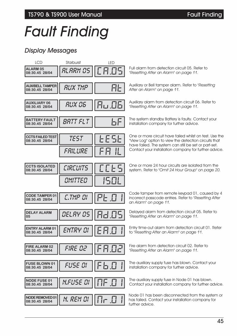
Fault FindingDisplay Messages
45
TS790 & TS900 User Manual Fault Finding
ALARM 0508:30.45 28/04
Full alarm from detection circuit 05. Refer to"Resetting After an Alarm" on page 11.ALARM 05 CA.05
AUX/BELL TAMPER08:30.45 28/04
Auxiliary or Bell tamper alarm. Refer to "ResettingAfter an Alarm" on page 11.AUX TMP AT
CCTS FAILED TEST08:30.45 28/04
One or more circuit have failed whilst on test. Use the"View Log" option to view the detection circuits thathave failed. The system can still be set or part-set.Contact your installation company for further advice.
TEST TEST
DELAY ALARM05
Delayed alarm from detection circuit 05. Refer to"Resetting After an Alarm" on page 11.DELAY 05 AD.05
AUXILIARY 0608:30.45 28/04
Auxiliary alarm from detection circuit 06. Refer to"Resetting After an Alarm" on page 11.AUX 06 Au.06
BATTERY FAULT08:30.45 28/04
The system standby Battery is faulty. Contact yourinstallation company for further advice.BATT FLT BF
FAILURE FAIL
CCTS ISOLATED08:30.45 28/04
One or more 24 hour circuits are isolated from thesystem. Refer to "Omit 24 Hour Group" on page 20.CIRCUITS CCTS
OMITTED ISOL
CODE TAMPER 0108:30.45 28/04
Code tamper from remote keypad 01, caused by 4incorrect passcode entries. Refer to "Resetting Afteran Alarm" on page 11.
C.TMP 01 PT.01
ENTRY ALARM 0108:30.45 28/04
Entry time-out alarm from detection circuit 01. Referto "Resetting After an Alarm" on page 11.ENTRY 01 EA.01
FIRE ALARM 0208:30.45 28/04
Fire alarm from detection circuit 02. Refer to"Resetting After an Alarm" on page 11.FIRE 02 FA.02
FUSE BLOWN 0108:30.45 28/04
The auxiliary supply fuse has blown. Contact yourinstallation company for further advice.FUSE 01 FB.01
NODE FUSE 0108:30.45 28/04
The auxiliary supply fuse in Node 01 has blown.Contact your installation company for further advice.N.FUSE 01 NF.01
NODEREMOVED0108:30.45 28/04
Node 01 has been disconnected from the system orhas failed. Contact your installation company forfurther advice.
N. REM 01 Nr.01

Display Messages (Cont.)
46
Fault Finding TS790 & TS900 User Manual
PA CODE 0908:30.45 28/04
Panic alarm generated by user 09 (PA Code). Referto "Resetting After an Alarm" on page 11.PANIC 09 PC.09
PANELLIDTAMPER08:30.45 28/04
Control panel cover has been removed. Refer to"Resetting After an Alarm" on page 11.LID TAMP LT
PHONELINEFAULT08:30.45 28/04
Telephone line fault (systems fitted with remotesignalling only). To silence the alarm, simply enter avalid passcode. If the fault persists contact yourinstallation company for further advice.
LINE FLT LF
PSU OVERLOAD!
The power supply within the control panel is beingoverloaded. Enter a valid passcode to silence thealarm and contact your installation company forfurther advice.
OVERLOAD OL
REMREMOVED0108:30.45 28/04
Remote keypad 01 has been disconnected from thesystem or has failed. Contact your installationcompany for further advice.
R. REM 01 rr.01
REM TAMPER 0108:30.45 28/04
The cover of remote keypad 01 has been removed.Refer to "Resetting After an Alarm" on page 11.R.TMP 01 rT.01
SERVICEREQUIRED08:30.45 28/04
Your system requires a service visit. The system canstill be used as normal, but you should contact yourinstallation company for further advice.
SERVICE rS
SYSTEM IS BUSYPLEASE WAIT.
Another user is operating the system from a differentremote keypad. When he/she has finished, allremote keypads will revert to normal.
BUSY BUSY
TAMPER 0508:30.45 28/04
Tamper alarm from detection circuit 05. Refer to"Resetting After an Alarm" on page 11.TAMP'R 05 TA.05
NODE TAMPER 0108:30.45 28/04
The cover of Node 01 has been removed. Refer to"Resetting After an Alarm" on page 11.N.TMP 01 NT.01
MAINSPOWEROFF08:30.45 28/04
Mains power to the system has been removed. Entera valid passcode to silence the alarm. The systemwill be maintained from its standby battery for aminimum of 8 hours. If the mains power is notrestored after 8 hours contact your installationcompany for further advice.
A.C. OFF PF
PA ALARM 0808:30.45 28/04
Panic alarm from detection circuit 08. Refer to"Resetting After an Alarm" on page 11.PA.ALM 08 PA.08
Press ENT toSet with L.F. ?
You are trying to set the alarm system with atelephone line fault (L.F.). If you press [ the systemwill continue to set or part-set but your remotesignalling device may not work if the alarm istriggered.
SET SET
WITH L.F. L.F.

Glossary of TermsAuxiliary Circuit - A detection circuit type which is monitored at all times. When triggered
it will only activate outputs that are programmed as auxiliary.
Chime - An optional facility which allows selected detection circuits togenerate a two-tone "Chime" when triggered.
Central Station - A permanently manned monitoring station used to receive alarmtransmissions via the telephone line from a remote signalling devicesuch as a digicom.
Detection Circuits - All detection devices, e.g. magnetic contacts, movement sensors,etc. are connected to detection circuits. Each circuit is allocated anumber which identifies the detection device. For example , a roomprotected by a movement sensor may be "Circuit 01", while a doorprotected by a magnetic contact may be "Circuit 02".
Digicom - Digital Communicator - A remote signalling device fitted to the systemwhich will transmit alarm status data via the telephone line to adedicated central station.
Downloading - A process which allows the alarm system to be remotely interrogatedand programmed via a computer and modem.
Duress - A means of entering a passcode which generates a silent alarm viathe digicom (if fitted) to a central station.
Exit/Entry route - The route for entering or leaving the protected premises when thesystem is being full or part-set.
Final Exit - The door or detector that is used for leaving and entering the premises.
Entry Time - A pre-set time delay to allow the user to enter the protected premisesand reach the remote keypad without causing an alarm.
Event Log - A record of system activity which is stored in a non volatile memory.
Exit Time - A pre-set time delay to allow the user to leave the premises when thealarm system is being set by the timed exit method.
Exit Terminator - An external push button switch required by some police forces which isused to set the system after leaving the premises.
Full Set - The state of the alarm system when it is protecting all wards.
Master User - The user(s) who are responsible for assigning new users to the alarmsystem.
Modem - A device for transmitting and receiving data to and from a computervia the telephone line.
Night Circuit - A detection circuit type that will generate a full alarm when the alarmsystem is set. When the alarm system is unset the detection circuit maybe triggered without causing an alarm.
Omit - To intentionally exclude the monitoring of one or more detectioncircuits when full or part setting the alarm system.
Part-Set - The state of the alarm system when it is protecting part of the premises.
47
TS790 & TS900 User Manual Fault Finding
Passcode - A unique four digit number which must be entered before the alarmsystem can be operated.
P.A. (Panic Alarm) - Emergency push button switch used to activate an alarm. The alarmsignal will also be transmitted to the central station if a remotesignalling device is fitted.
Remote Keypad - A device located away from the main control panel that is used tooperate the alarm system.
Reset - The action required to return the system to its normal state after analarm.
Set - To arm the alarm system or wards.
System Open - The normal unset state of the system.
System Set - The full set state of the the alarm system.
Tamper - An alarm caused by the system being interfered with physically or bytoo many unauthorised keypad entries.
24 Hour Circuit - A circuit that is monitored at all times. When triggered in the unsetcondition a local alarm is generated (Internal sounders only). Whentriggered in full or part-set condition a full alarm is generated.
Unset - To disarm the alarm system or areas (wards).
Users - Persons allocated a passcode which allows them to operate thealarm system.
Wards - A group of detection circuits that may be set or unset independently ofeach other.
48
Fault Finding TS790 & TS900 User Manual

User Record
UserNo User Type User Name
Set/Unset Wards
System Ward A Ward B Ward C
01 Master 4 4 4 4
02
03
04
05
06
07
08
09
10
11
12
13
14
15
16
17
18
19
20
21
22
23
24
25
26
27
28
29
30
31
49
TS790 & TS900 User Manual System Records

Detection Circuit Record
CircuitNo Location Omit Chime
Circuit in Wards
System A B C
01
02
03
04
05
06
07
08
09
10
11
12
13
14
15
16
17
18
19
20
21
22
23
24
25
26
27
28
50
System Records TS790 & TS900 User Manual
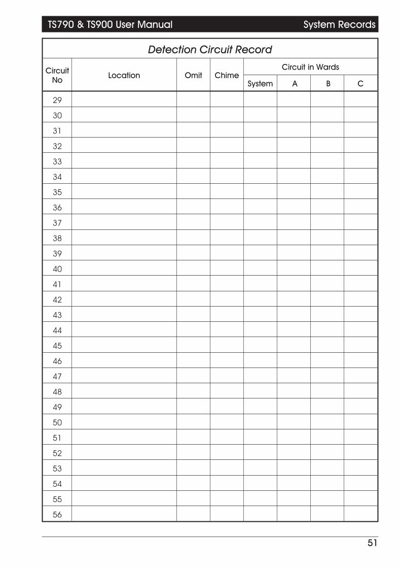
Detection Circuit Record
CircuitNo Location Omit Chime
Circuit in Wards
System A B C
29
30
31
32
33
34
35
36
37
38
39
40
41
42
43
44
45
46
47
48
49
50
51
52
53
54
55
56
51
TS790 & TS900 User Manual System Records

Service RecordDate Engineer Action
Installation InformationBell Delay: Bell Duration:
Master User Access: Full Limited Remote Signalling: Yes No
Downloading: Yes No User Authorisation: Yes No
Set with power off: Yes No Set with Line Fault: Yes No
Installation Engineer: ________________________________________________________
Installation Company: ________________________________________________________
Address: ________________________________________________________
________________________________________________________
________________________________________________________
________________________________________________________
Telephone: ________________________________________________________
Central Station: ________________________________________________________
Telephone: ________________________________________________________
496488 Issue 1