pakscan paktester (field test unit) technical manual pakscan paktester (field test unit) technical...
TRANSCRIPT

Publication S178E Issue 1.1 November 2000
Baud Rate = 1200Add=001Mode=dig
Pakscan Paktester (Field Test Unit)
Technical Manual
Z24539-02
nichtunterspannungoffnen
ne pasouvrirsoustension
warning-attention-achtungdo notopenwhileenergised
FLP/IP68/
I IB T 4 (Tamb=+70 C )EExd Certificate No.xxxxxxxx
Bath. EnglandRotork Controls Ltd.
enclosurewiringdiag.no.
serialnumber type
Pak-Box

2 of 82
Paktester - Publication S178E Issue 1.1 November 2000
As we are continually developing our products their design is subject to change without notice The contents of this document are copyright and must not be reproduced without the written permission of Rotork Controls Ltd.
THIS MANUAL REPLACES THE PAKTESTER MANUAL R5161-016 AND RELATES TO PAKTESTERS FITTED WITH V5.0 FIRMWARE OR GREATER Related Documents: [1] Pakscan Master Station Modbus Interface Specification S171E [2] Pakscan IQ Field Unit Technical Manual S172E [3] Pakscan Integral Field Control Unit Technical Manual S173E [4] Pakscan General Purpose Field Control Unit Technical Manual S174E [5] Pakscan IQ Analogue Input Field Unit S164E Abbreviations used in this document: CA = Close Auxilliary Switch CT = Close Torque Limit Switch DV = Desired Value ESD = Emergency Shut Down FCU = Field Control Unit FTU = Field Test Unit, - Paktester GPFCU = General Purpose Field Control Unit I1 = Intermediate Auxiliary Switch 1 I4 = Intermediate Auxiliary Switch 4 MV = Measured Value NC = Normally Closed (contact) NO = Normally Open (contact) OA = Open Auxiliary Switch OT = Open Torque Limit Switch

3 of 82
Paktester - Publication S178E Issue 1.1 November 2000
Contents 1. INTRODUCTION 2. OPERATOR INTERFACE 2.1. Liquid Crystal Display 2.2. Keypad 2.3. Operation 3. INITIAL POWER ON 3.1. System Status Display 4. PAKSCAN I DISPLAY MODES 4.1. Field Status Display (I) 4.2. Field Alarm Display (I) 4.3. Program Display (I) 5. PAKSCAN II DISPLAY MODES 5.1. Field Status Display (II) 5.2. Field Alarm Display (II) 5.3. Program Display (II) 5.3.1. 1600 MkV, AQ and Q 5.3.2. IQ 5.3.3. GPFCU 5.3.4. IQ Analogue Card 5.3.5. Flowpak 5.4. Diagnostic Display (II) 6. TECHNICAL DESCRIPTION 6.1. General 6.2. Two-Wire Interface 7. MAINTENANCE

4 of 82
Paktester - Publication S178E Issue 1.1 November 2000
A APPENDIX A1 Paktester Options - Pakscan 1 A2 Paktester Options - Pakscan 2 (Integral Actuator) A3 Paktester Options - Pakscan 2 (IQ Actuator) A4 Paktester Options - Pakscan 2 (GPFCU, Actuator Mode) A5 Paktester Options - Pakscan 2 (GPFCU, General Purpose Mode) A6 Paktester Options - Pakscan 2 (IQ Analogue Card) A7 Paktester Options - Pakscan 2 (Flowpak Actuator) A8 Use of Paktester with non-Actuator Field Units A9 Programming example A10 Examples of IQ mask

5 of 82
Paktester - Publication S178E Issue 1.1 November 2000
1. INTRODUCTION This manual is based on a Paktester with an EPROM with a software version of V5.0 or higher. The software version of the EPROM is displayed on the second line of the display briefly after turning the Paktester on. The Paktester is a hand held battery powered device designed to interrogate a Pakscan FCU via the 2 wire interface. It emulates the functions of a single channel master station to provide alarm and status information as well as giving valve operating commands. Two protocols are supported, namely the earlier Pakscan I protocol and the current Pakscan II protocol, (which is faster and more flexible). The Paktester can be used to operate various types of FCUs available including those specifically dedicated to the Pakscan I or Pakscan II loop protocols and also with the Integral type which can be supplied in either version. The Paktester is used to program the following: a/ - The address and baud rate for type 1 (digital control) Integral FCUs fitted to Rotork IQ, 1600 A Mk5, AQ Mk2, Q and Flowpak range actuators and all Pakscan II GPFCUs. b/ - The above plus analogue report time and deadband along with motion inhibit time and deadband, for the type 3 (position control) FCUs. c/ - All of the above plus additional parameters such as limited range positioning, valve travel time, torque filter factor, torque update timeout, torque deviation threshold and auxiliary input mask for the IQ FCU. d/ - Item a/ plus the I/P scaling factors as well as the input type (current or voltage) for the IQ analogue card. e/ - Items a/ and b/ for the GPFCU in actuator mode f/ - For a GPFCU in GPFCU mode, item a/ plus the O/P mode of the relays, analogue report time and deadband, digital I/P mask, as well as I/P and O/P scaling factors can be programmed. g/ - Items a/ and b/ plus the manual release pulse timer for the Flowpak FCU. This manual describes the general operation of the Paktester and where relevant provides discrete sections relating to the applicable protocol. Knowledge of the protocol is unnecessary, but familiarisation with the particular type of Field Unit in use, (via a technical manual) is recommended.

6 of 82
Paktester - Publication S178E Issue 1.1 November 2000
Fig 1: Paktester connection
Fig 2: Incorrect connection
The master station must not be connected to the Field Unit whilst the Paktester is connected otherwise both units will attempt to generate loop current and the Paktester could be damaged.
Connection to the Field Unit may be between the "A" and "C" terminals or between the "C" and "B" terminals, thereby allowing both loopback circuits to be tested.

7 of 82
Paktester - Publication S178E Issue 1.1 November 2000
2. OPERATOR INTERFACE 2.1. Liquid Crystal Display (LCD) The Paktester is fitted with a dual line, 16 character LCD to provide the operator with the FCU status information. Section 3 of this manual gives full details of the actual displays which vary according to the mode selected and the type of field unit connected. The extreme right hand character in the lower row of the display is reserved for alarm indication, which is blank under non-alarm conditions but shows a flashing "A" when an alarm is active. The flashing “L” in the upper row indicates that the FCU is in loopback on mode. This is not an alarm condition as the FCU needs to be in loopback mode to provide a return path for the loop current. User variables are highlighted by a flashing cursor, which when positioned over the selected parameter, may be altered by depressing the "up-arrow" or "down arrow" keys to achieve the required setting. Where several parameters are accessible on the single display, pressing the "SELECT" key moves the cursor to the next parameter. Multiple page displays are accessed by repeated operation of the key(s) used to invoke the display. 2.2 Keypad Brief descriptions of the key and key combination functions are shown in figure 3. Note that some combinations are only enabled in certain modes, (e.g. CALibrate commands are not used in Pakscan I applications). The "SHIFT" key is used to select the "upper" functions on a number of other keys (e.g. "SHIFT" "PROG" selects the CALibrate mode where calibration data may be sent to the Field Unit. Generally "SHIFT" functions are less used than single key functions. Where applicable the "SHIFT" key is used to "SELECT" a particular parameter on the relevant display to enable alteration etc.

8 of 82
Paktester - Publication S178E Issue 1.1 November 2000
2.3 Operation When first powered up the Paktester displays the internal software reference and then performs a self test routine. Failure during this test causes an error message to be displayed. Successful completion of the self test enters the unit into the System Display mode. Before communication with the FCU can be achieved, the following parameters need to be checked and re-set if necessary to accommodate the particular system. These are: Parameters Default settings i) Pakscan I or II protocol Protocol = 2 (Pakscan II) ii) Applicable Baud rate Baud rate = 1200 iii) Appropriate FCU address. Address = AU (auto) Note: if items i) and ii) are correctly selected the FCU address can easily be ascertained by selecting AU (auto) for this parameter. When "loop back" has been established the FCU will communicate the correct address which then appears in the Paktester display. Failure to display a valid address indicates an inability to communicate, therefore check FCU connections and items i) and ii) are correctly selected Once communications are established the keypad may be used as described to select alternative display modes in order to monitor and control the FCU.

9 of 82
Paktester - Publication S178E Issue 1.1 November 2000
NOT OPEN De-energise Relay 2 OPEN (RLY 2) Energise Relay 2 (OPEN) or increments "dv" in "position" mode NOT STOP De-energise Relay 3 STOP (RLY 3) Energise Relay 3, (STOP) NOT CLOSE De-energise Relay 1 CLOSE (RLY 1) Energise Relay 1 (CLOSE) or decrements "dv" in “position" mode UP ARROW Increments the selected parameter indicated by the flashing cursor SHIFT Selects the shift function of other keys. SELECT Selects the next user alterable parameter on this display
DOWN ARROW Decrements the selected parameter indicated by the flashing cursor
FIELD STATUS Displays Field Unit status FIELD ALARMS Displays alarm information SYSTEM STATUS Displays system parameters NOT ESD De-energise Relay 4 ESD (RLY 4) Energise Relay 4, (ESD) CAL Enter calibrate mode PROG Enter program mode ALARM ACCEPT Accepts displayed alarms and updates alarm status
Fig 3: Key and key combination functions
STOP (RLY3)
NOT
SELECT
SHIFT
FIELD STATUS OPEN
(RLY2)
NOT
ESD RLY4
NOT
FIELD ALARMS
PROG
CAL
SYSTEM STATUS
ALARM ACCEPT
CLOSE (RLY1)
NOT

10 of 82
Paktester - Publication S178E Issue 1.1 November 2000
This page is intentionally blank

11 of 82
Paktester - Publication S178E Issue 1.1 November 2000
3. INITIAL POWER ON The actual display presented to the operator is dependant upon ; (a) the display mode selected at the keypad, and (b) the protocol type applicable, since the Pakscan II version supports a greater variety of FCUs and a wider range of data. Details of the various display formats are given in the following sub-sections 3.1. System Status Display Page one of the System Status Display allows the user to select the required protocol. The second page of the System Status Display contains details of the basic Field Unit settings. This allows the operator to alter the Baud rate, the FCU address and the mode of operation via the SELECT and UP/DOWN keys. It should be stressed here that values do not affect the FCU settings - they only alter how the test unit attempts to talk to the FCU. The Baud rate may be selected as: 110 baud 300 baud 600 baud 1200 baud 2400 baud – (Pakscan II only)
Baud Rate=1200 Add=001 Mode=dig
Select protocol Pakscan 2

12 of 82
Paktester - Publication S178E Issue 1.1 November 2000
The address may be in the range: from 001 to 032 - Pakscan I & II FCUs from 001 to 240 - Pakscan IIE & IIS FCUs Mode may be "dig" (digital - on/off control) "ang" (analogue - on/off control + analogue feedback) "pos" (position - position control) "gp" (general purpose field control unit) “iqa” (IQ analogue I/P card) Items "dig", "ang" or "pos" are actuator control options - selectable via the arrow keys. The "gp" option is fixed if the Paktester detects a GPFCU replying to it and the “iqa” option is fixed if the Paktester detects an IQ analogue card. Page three of the System Status display indicates the type of FCU which the test unit has detected. or or or or or
Field Unit Type= IQ Actuator
Field Unit Type= Q Actuator
Field Unit Type= Ext Actuator
Field Unit Type= General Purpose
Field Unit Type= P-Pak Actuator
Field Unit Type= ???

13 of 82
Paktester - Publication S178E Issue 1.1 November 2000
4. PAKSCAN I DISPLAY MODES Only traditional actuator controlling FCU's are explicitly supported by the Paktester in Pakscan I mode. 4.1. Field Status Display (I) In digital mode the following actuator status information is available:
(OA = OAS, OT = OTLS, I1 = IAS1) (CA = CAS, CT = CTLS, I4 = IAS4)
Code:- 0 = inactive i.e. not true 1 = active i.e. true OA = 0 or 1 flashing indicates valve opening CA = 0 or 1 flashing indicates valve closing In "analogue" and "position" modes the following actuator status information is available:
(DV = desired value) (MV = measured value)
Code:- ddd = 0 to 255 (pos mode) = xx (ang mode) mmm = 0 to 255 (pos & ang mode) i.e. intermediate auxiliary switch status (IAS1 and IAS4) has been replaced by the desired and measured values. In “position” mode the desired value may be altered using the OPEN and CLOSE keys. Measured values are not corrected for span and zero. In "analogue" mode DV is meaningless and the OPEN and CLOSE keys act as in "digital" mode.
OA=1 OT=0 I1=0 CA=1 CT=0 I4=0
OA=1 OT=0 DVddd CA=1 CT=0 MVmmm

14 of 82
Paktester - Publication S178E Issue 1.1 November 2000
4.2. Field Alarm Display (I) The alarm display may take a number of formats depending upon alarm type present. During normal operation the display appears as follows;
As before, the "A" in the bottom right hand corner indicates an alarm which has not been accepted or is still active. The characters on the top row indicate via the key which alarms are active. This display covers all the actuator and FCU alarms. If communications with the FCU are not established then "ALARM STATUS" is replaced by "COMMS FAILURE". In the Paktester, a low battery condition is detected the message is replaced by "LOW BATTERY" and on memory test fail "SELF TEST FAILURE" is displayed on power-up. All the fault codes are tabulated in table 1: Note that GPFCUs and IQ analogue cards generate a subset of the actuator alarms and may be viewed in an identical manner. (Only "F", "W", "P" and "L" alarms are valid).
RL S M L FIELD ALARMS A
Position Display Meaning
1 R Relay (monitor)
2 L Local stop
3 T Thermostat
4 C Control not available
5 (reserved)
6 S Start / stop fail
7 J Jammed valve
8 O Obstructed valve
9 E End of travel / stop fail
10 M Manual operation
11 (reserved)
12 F Memory fault
13 W Watchdog
14 P Power on reset
15 (reserved)
16 L (flashing) Loopback on
Table 1: Paktester fault codes

15 of 82
Paktester - Publication S178E Issue 1.1 November 2000
4.3. Program Display (I) The Program Display, invoked by pressing "PROG", is used to change user alterable parameters in FCUs containing non-volatile memory (EEPROM). When the operating mode of the Paktester is set to "pos", (position control), the operator will be prompted to alter four parameters: Baud Rate:
This is the rate at which data is transmitted around the loop. All devices on the loop as well as the master station should be set to the same rate.
Address: This is the unique device identifier. Each device on the loop should have a unique address, which should also be no greater than the total number of FCU’s that the master station can address.
Motion Inhibit Timer: This sets the time between successive starts of the actuator and can be used to prevent the motor exceeding the rated number of starts per hour.
Deadband: The deadband setting is used to prevent the actuator from hunting. Its value is dependent upon the speed of the actuator and the degree of accuracy required. Once the actuators position reaches the deadband it will stop the motor. However, if the actuator has a high speed it can overshoot the required setting and the actual stopping position could be outside the other deadband limit. It will then, after the time period set in the Motion Inhibit Timer, head towards the required setting again. If the control has to be exact then a small deadband, (2%), should be set, however, if a more tolerant control is permitted then a deadband of 5% would be acceptable.
N.B. 1/ Not all FCUs carry EEPROM's and hence not all are programmable. 2/ A write protect link may need to be removed on the FCU to allow programming and re-fitted once programming is complete. 3/ Programming may be disabled if the FCU is not in loopback. When the Paktester is in modes other than position control the second page, (Motion Inhibit Timer and Deadband), is omitted. The last page invites the operator to send the parameters to the FCU by pressing the up and down arrow keys simultaneously. Once programming has been initiated the Paktester will ask the operator to wait whilst the parameters are downloaded. When this is complete the Paktester will interrogate the Field Unit to check the parameters. It is the operators responsibility to ensure that correct programming has been carried out.

16 of 82
Paktester - Publication S178E Issue 1.1 November 2000
This page is intentionally blank

17 of 82
Paktester - Publication S178E Issue 1.1 November 2000
5. PAKSCAN II DISPLAY MODES All FCU's are supported by the Paktester in Pakscan II mode. 5.1. Field Status Display (II) 5.1.1 Actuator Field Status Display In digital mode the following actuator status information is available:
(OA = OAS, OT = OTLS, I1 = IAS1) (CA = CAS, CT = CTLS, I4 = IAS4)
Code:- 0 = inactive i.e. not true 1 = active i.e. true OA = 0 or 1 flashing indicates valve opening CA = 0 or 1 flashing indicates valve closing (Note that with Pakscan II FCUs there is no torque limit switch and consequently OT and CT have no relevance). In "analogue" and "position" modes the following actuator status information is available:
(DV = desired value) (MV = measured value)
Code:- ddd = 0 to 255 (pos mode) = xx (ang mode) mmm = 0 to 255 (pos & ang mode) i.e. intermediate auxiliary switch status (IAS1 and IAS4) has been replaced by the desired and measured values. In “position” mode the desired value may be altered using the OPEN and CLOSE keys. Measured values are not corrected for span and zero. In "analogue" mode DV is meaningless and the OPEN and CLOSE keys act as in "digital" mode.
OA=1 OT=0 I1=0 CA=1 CT=0 I4=0
OA=1 OT=0 DVddd CA=1 CT=0 MVmmm

18 of 82
Paktester - Publication S178E Issue 1.1 November 2000
5.1.2. GPFCU Field Status Display For actuator control FCU displays see section 3.2., GPFCUs are supported by the following additional displays; Digital Inputs:
The first two pages show the state, "1" = active, "0" = inactive, of the eight digital inputs available on a GPFCU.
Digital Outputs: Page three shows the operating mode of the digital outputs, (fleeting/maintained), and their status, ("1" = energised, "0" = de-energised).
Analogue Inputs: Page four shows the analogue values, (0 to 100%), after calibration, measured at the two analogue inputs.
Analogue Output: The calibrated analogue output is displayed and may be raised/lowered by use of the up-arrow and down-arrow keys. Large changes to the analogue output may be made by using the "select" key to move the cursor to the tens column of the displayed value.
DIGITAL INPUTS 1=0 2=0 3=1 4=1
DIGITAL INPUTS 5=0 6=0 7=0 8=0
DOUTS=FLEETING 1=0 2=0 3=0 4=0
ANALOG INPUTS(%) A=000.0 B000.0
ANALOG OUTPUT =000.0%

19 of 82
Paktester - Publication S178E Issue 1.1 November 2000
5.2. Field Alarm Display (II) The alarm display may take a number of formats depending upon alarm type present. During normal operation the display appears as follows;
As before, the "A" in the bottom right hand corner indicates an alarm which has not been accepted or is still active. The characters on the top row indicate via the key which alarms are active. This display covers all the actuator and FCU alarms. If communications with the FCU are not established then "ALARM STATUS" is replaced by "COMMS FAILURE". In the Paktester, if a low battery condition is detected the message is replaced by "LOW BATTERY" and on memory test fail "SELF TEST FAILURE" is displayed on power-up. All the fault codes are tabulated in table 2: Note that GPFCUs generate a subset of the actuator alarms and may be viewed in an identical manner. (Only "F", "W", "P" and "L" alarms are valid).
RL S M L FIELD ALARMS A
Position Display Meaning
1 R Relay (monitor)
2 L Local stop
3 T Thermostat
4 C Control not available
5 (reserved)
6 S Start / stop fail
7 J Jammed valve
8 O Obstructed valve
9 E End of travel / stop fail
10 M Manual operation
11 (reserved)
12 F Memory fault
13 W Watchdog
14 P Power on reset
15 (reserved)
16 L (flashing) Loopback on
Table 2: Paktester fault codes

20 of 82
Paktester - Publication S178E Issue 1.1 November 2000
5.3. Program Display (II) The Program Display, invoked by pressing "PROG", is used to change user alterable parameters in FCUs containing non-volatile memory (EEPROM). When the operating mode of the Paktester is set to "pos", (position control), the operator will be prompted to alter various parameters: 5.3.1. Integral FCU – 1600 MkV, AQ MkII and Q FCU Successful programming can only occur if the EEPROM write enable link on the FCU is removed and the FCU is in loopback. (The links are fitted only on the very early Pakscan II FCU boards – pre 1993). For optimum performance of the Pakscan loop, programming of Pakscan II FCUs the operating mode needs to be set to "pos" irrespective of whether the FCU is an ON/OFF, Analogue or Position controller. Baud Rate:
This is the rate at which data is transmitted around the loop. All devices on the loop as well as the master station should be set to the same rate.
Address:
This is the unique device identifier. Each device on the loop should have a unique address, which should also be no greater than the total number of FCU’s that the master station can address.
Motion Inhibit Timer: This sets the time between successive starts of the actuator and can be used to prevent the motor exceeding the rated number of starts per hour.
Deadband:
The deadband setting is used to prevent the actuator from hunting. Its value is dependent upon the speed of the actuator and the degree of accuracy required. Once the actuators position reaches the deadband it will stop the motor. However, if the actuator has a high speed it can overshoot the required setting and the actual stopping position could be outside the other deadband limit. It will then, after the time period set in the Motion Inhibit Timer, head towards the required setting again. If the control has to be exact then a small deadband, (2%), should be set, however, if a more tolerant control is permitted then a deadband of 5% would be acceptable.

21 of 82
Paktester - Publication S178E Issue 1.1 November 2000
Analogue Timeout: Sets the time period between successive updates of the analogue inputs over the two wire link. Note, if this time is set short the loop scan time will be extended by the additional analogue data being sent. The recommended min value for “pos” FCUs is 10 x loop scan time or 30 seconds, whatever is the greater. For ON/OFF i.e. “dig” FCUs set this value to 0
Analogue Deadband:
Sets the deviation allowed between the current analogue input and the previously reported value. When this deviation is exceeded a new analogue value is reported. The recommended value for “pos” FCUs is 5% For “dig” FCU’s set this value to 0
N.B. 1/ Programming may be disabled if the FCU is not in loopback. 2/ Some early Pakscan II FCUs were fitted with a write protect link that will need to be removed to allow programming of the FCU When the Paktester is in modes other than position control the second page, (Motion Inhibit Timer and Deadband and Analogue Timeout and Deadband), are omitted. The last page invites the operator to send the parameters to the FCU by pressing the up and down arrow keys simultaneously. Once programming has been initiated the Paktester will ask the operator to wait whilst the parameters are downloaded. When this is complete the Paktester will interrogate the Field Unit to check the parameters. It is the operators responsibility to ensure that correct programming has been carried out. 5.3.2. IQ In addition to the parameters described in section 5.3.1., the IQ FCU has the following further parameters which may be set via the Paktester. Valve Travel Time
This sets the time that the centre column can continuously rotate before an alarm , (VTT), is generated. This should be set for a value greater than the valve travel time. A VTT alarm will not stop the centre column rotating.

22 of 82
Paktester - Publication S178E Issue 1.1 November 2000
Limited Range Positioning It is possible to set the range of travel, in positioning mode, to be different to the 0% and 100% values corresponding to end of travel. This is used when the actuator normally only has to travel over a portion of its complete range. When set, the position value returned over the 2 wire loop will correspond to the % open between the set positions. If the actuator is used in digital mode, it will travel between its true 0% and 100% values.
Auxiliary I/P Mask The IQ FCU can accept 4 external I/P’s, called AUX1-4, either in the form of digital signals from level switches etc to be fed back to the master station via the 2 wire loop, or as remote pushbutton I/P’s to control the actuator. AUX1-4 each have two bits associated with them, a function bit, (bits 5-8), and an invert bit, bits 1-4). When bits 5-8 are set to 0, AUX1-4 are used as digital I/P’s to be sent to the host. Bits 1-4 are then used to condition the signals, i.e. they can be transmitted to the master station either in their true state, (with relevant bits set to 1), or inverted, (with bits set to 0). With bits 5-8 set to 1, the actuator will accept the AUX I/P’s as remote pushbutton control I/P’s. In this case bits 1-4 determine whether the motor will be energised with a closed contact, (with relevant bits set to 1), or with an open contact, (with bits set to 0). For examples of mask settings see appendix A10, (page 80).
Torque Deviation Threshold Sets the deviation allowed between the current torque and the previously reported torque values. When this deviation is exceeded a new torque value is reported. When set to zero the torque will only be transmitted when requested by the Paktester or master station, or when the timeout value is exceeded. The recommended value is 00 when torque data is not required otherwise set to 5%
Torque Update Timeout
This is similar to the analogue timeout in that it sets the time period between successive updates of the instantaneous torque readings over the 2 wire loop. If this is set to zero the torque will only be transmitted when requested or when the deviation threshold is exceeded.

23 of 82
Paktester - Publication S178E Issue 1.1 November 2000
Torque Filter Factor This relates to the 8 torque readings taken over the full travel of the actuator. With the filter set to 0 the raw torque data will be fed back to the master station. Filtering allows for an averaging of the latest readings with the historical torque readings. The filter may be set in the range 0 - 255 and gives a torque reading as follows;
Reported value = [ new value x ( 1 - filter factor) ] + [ old value x (filter factor) ] 256 256 Note on Torque reporting; If torque data is not required for normal use it is recommended that automatic torque data reporting is turned off, i.e. deviation = 00, timeout = 000 and filter factor set to the factory default of 127. This will allow for a much faster loop scan time as the loop will not be congested with unwanted torque data. The torque will still be available for collection by the master station / host upon request. When an IQ actuator is used on a loop controlled by a Pakscan 2 master station fitted with software less than V2.2, automatic torque data reporting must be turned off as the master station is unable to accept torque data. 5.3.3. GPFCU a/ Programming In addition to being able to be configured as actuator FCUs, GPFCUs have a number of additional programmable parameters when set to General Purpose mode; Relay Output Mode:
Selects whether the relay outputs are fleeting or maintained contacts.
Analogue Input 1 Deadband: Sets allowed deviation for analogue input 1, (see explanation in 5.3.1.).
Analogue Input 2 Deadband: Sets allowed deviation for analogue input 2, (see explanation in 5.3.1.).
Analogue Report Timeout: Sets update timeout for both analogue inputs, (see explanation in 5.3.1.).
24 of 82
Paktester - Publication S178E Issue 1.1 November 2000
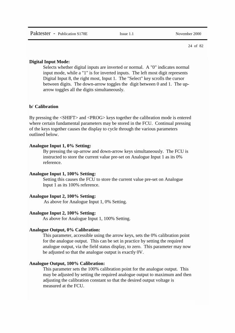
Digital Input Mode: Selects whether digital inputs are inverted or normal. A "0" indicates normal input mode, while a "1" is for inverted inputs. The left most digit represents Digital Input 8, the right most, Input 1. The "Select" key scrolls the cursor between digits. The down-arrow toggles the digit between 0 and 1. The up-arrow toggles all the digits simultaneously.
b/ Calibration By pressing the <SHIFT> and <PROG> keys together the calibration mode is entered where certain fundamental parameters may be stored in the FCU. Continual pressing of the keys together causes the display to cycle through the various parameters outlined below. Analogue Input 1, 0% Setting:
By pressing the up-arrow and down-arrow keys simultaneously. The FCU is instructed to store the current value pre-set on Analogue Input 1 as its 0% reference.
Analogue Input 1, 100% Setting: Setting this causes the FCU to store the current value pre-set on Analogue Input 1 as its 100% reference.
Analogue Input 2, 100% Setting: As above for Analogue Input 1, 0% Setting.
Analogue Input 2, 100% Setting: As above for Analogue Input 1, 100% Setting.
Analogue Output, 0% Calibration: This parameter, accessible using the arrow keys, sets the 0% calibration point for the analogue output. This can be set in practice by setting the required analogue output, via the field status display, to zero. This parameter may now be adjusted so that the analogue output is exactly 0V.
Analogue Output, 100% Calibration: This parameter sets the 100% calibration point for the analogue output. This may be adjusted by setting the required analogue output to maximum and then adjusting the calibration constant so that the desired output voltage is measured at the FCU.

25 of 82
Paktester - Publication S178E Issue 1.1 November 2000
5.3.4. IQ Analogue Card The IQ Analogue card sits inside an IQ actuator between the FCU and the main PCB. It is a separate node on the Pakscan highway and as such must be programmed with its own unique address and the loop speed (see section 5.3.1.) The card is designed to feed two external analogue, 4-20mA or 0-5V signals via itself onto the Pakscan loop and on to the master station. It has the same programme analogue I/P options as the GPFCU (see section 5.3.3.). The only additional programmable feature is: Analogue Input Signal:
The Analogue I/P card has two independent inputs. The choice of I/P signal ( 4-20mA or 0-5V) is configurable. I/Ps 1 and 2 do not have to be set to the same type of I/P signal.
5.3.5. Flowpak The Flowpak has the same programmable settings as the Integral FCU (see section 5.3.1.) plus two additional options: Actuator Speed:
This parameter selects the time needed by the FCU to detect that the actuator is moving by looking at the potentiometer feedback. There are three settings: SLOW i.e. < 4 sec, NORMAL i.e. between 4 and 12 sec FAST i.e. > 12 sec If a coil has been energised and the potentiometer feedback hasn’t changed by more than 1% within the time period programmed, the FCU will declare that the valve has jammed.
Manual Release:
The Flowpak has a manual control override feature. If the actuator is closed and an open command is requested, a close command is initially sent to release the manual control, followed by a delay period equal to the manual release time, before the open command is sent. (The opposite is true if the actuator were at the open limit). This delay period allows the hydraulic fluid to stabilise between the two conflicting commands.

26 of 82
Paktester - Publication S178E Issue 1.1 November 2000
5.4. Diagnostic Display (II) By pressing the <SHIFT> and <FIELD STATUS> display keys simultaneously, diagnostic data from the FCU may be examined. The first page allows access to data from any block and parameter (see Pakscan Master Station Modbus Interface Specification – S171E, for reference) in the FCU. When in this mode the Paktester polls the FCU for data and, if available, displays it in hex format. Page 2 displays the data, (in hex), and block number of the most recently reported exception data from the Field Unit.

27 of 82
Paktester - Publication S178E Issue 1.1 November 2000
6. TECHNICAL DESCRIPTION 6.1. Power Supply The Paktester is designed to run of a nominal 9V dc battery (PP3). The unit will operate over the range 6V to 11V but will indicate "low battery" below 7V. 6.2. Two-wire Interface The Paktester provides the 20mA drive necessary to power the line up to a maximum of 5V. The line current is switched on prior to transmission and off when reception is complete in order to prolong battery life. Two wires are provided carrying the current out of (brown) and into (blue) the Paktester. The output is short circuit and over voltage protected in case of incorrect connection. In order for the Paktester to be able to communicate with a FCU, the current loop must be complete. (Note, for the Paktester to automatically determine the FCU address the correct Baud rate must be set and the "ADDress" must be set to AU. To re-programme the FCU it must have entered loopback.) Since the Paktester has limited drive capability it will only drive a line resistance of up to 250 Ohms. It may still however be used to test FCU's by connecting to the master station field wiring in the control room, if only one unit is powered up at a time. In this case the Paktester will only be able to communicate with the first powered FCU on the loop. Once tested this unit may be powered down and the next unit tested and so on. This method has the benefit of testing both the FCU and the wiring. 7. MAINTENANCE All units are subjected to stringent inspection and test procedures during manufacture to ensure maximum reliability. No routine maintenance, other than battery replacement, is required. In the event of a suspected malfunction we recommend that due to the complexity of the unit it should be returned to Rotork Controls for checking/repair.

28 of 82
Paktester - Publication S178E Issue 1.1 November 2000
This page is intentionally blank

29 of 82
Paktester - Publication S178E Issue 1.1 November 2000
APPENDIX
A 1/1 PAKTESTER OPTIONS – PAKSCAN 1 (INTEGRAL ACTUATOR FCU’S)
SWITCH ON
Select protocol Pakscan 2
FIELD TEST UNIT PAK (1,2) V5.1
PRESS
Select protocol Pakscan 1
SYSTEM STATUS
Baud Rate = 1200 Add=001Mode=dig
SELECT CORRECT BAUD RATE (IF NECESSARY)
OR Y
N
THEN Y
N
Baud Rate = 1200 Add=001Mode=dig
PRESS
PRESS TWICE
OPTIONS
OPERATION
RE-PROGRAMMING
CONTINUED
INTERROGATION
SELECT
SHIFT SELECT CORRECT MODE (IF NECESSARY)

30 of 82
Paktester - Publication S178E Issue 1.1 November 2000
Baud Rate = 1200 Add=001Mode=dig
PRESS
OPERATION
CONTINUED
INTERROGATION
ALARM DISPLAY
FIELD ALARMS
Position Display Meaning 1 R Relay (monitor) 2 L Local stop 3 T Thermostat 4 C Control not available 5 (reserved) 6 S Start / stop fail 7 J Jammed valve 8 O Obstructed valve 9 E End of travel / stop fail 10 M Manual operation 11 (reserved) 12 F Memory fault 13 W Watchdog 14 P Power on reset 15 (reserved) 16 L (flashing) Loopback on
ALARM ACCEPT
PRESS
TO ACCEPT ALARM
FIELD STATUS
FIELD STATUS
PRESS
RL S M L FIELD ALARMS A
DIGITAL (TYPE 1)
POSITIONAL (TYPE 3)
CLOSE (RLY1)
NOT
STOP (RLY3)
NOT
OPEN (RLY2)
NOT NOT
ESD (RLY4)
OPEN STOP CLOSE ESD
A 1/2
OA=0 OT=0 I1=0 CA=1 CT=0 I4=0
OA=0 OT=0 DVddd CA=1 CT=0 MVmmm
Code Description
OA Open Limit Switch
CA Closed Limit Switch
OT Open Torque Limit Switch
CT Close Torque Limit Switch
I1 Motor Stopped (Between limits)
I4 Motor Running
DV Desired Value
MV Measured Value
31 of 82
Paktester - Publication S178E Issue 1.1 November 2000
Baud Rate = 1200 Add=001Mode=dig
CONTINUED
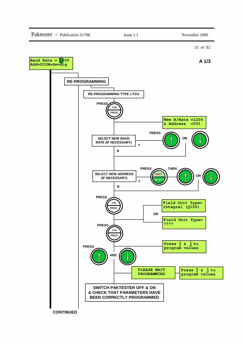
RE-PROGRAMMING TYPE 1 FCU
PRESS
PRESS
Field Unit Type= Integral (Q100)
Field Unit Type= ????
New B/Rate =1200 & Address =001
PROG
CAL
OR
Y
N
THEN
Y
N
SELECT
SHIFT SELECT NEW ADDRESS (IF NECESSARY)
OR
PRESS
PROG
CAL
PROG
CAL
PRESS
OR
PRESS
PRESS
AND
Press & to program values
PLEASE WAIT PROGRAMMING
SWITCH PAKTESTER OFF & ON & CHECK THAT PARAMETERS HAVE BEEN CORRECTLY PROGRAMMED
Press & to program values
A 1/3
SELECT NEW BAUD RATE (IF NECESSARY)
RE-PROGRAMMING

32 of 82
Paktester - Publication S178E Issue 1.1 November 2000
Baud Rate = 1200 Add=001Mode=pos
RE-PROGRAMMING TYPE 3 FCU
PRESS
PRESS Field Unit Type= Integral (Q100)
Field Unit Type= ????
New B/Rate =1200 & Address =001
PROG
CAL
OR
Y
N
THEN
Y
N
SELECT
SHIFT OR PRESS
PROG
CAL
PROG
CAL
PRESS
OR
PRESS
PRESS
AND
Press & to program values
PLEASE WAIT PROGRAMMING
SWITCH PAKTESTER OFF & ON & CHECK THAT PARAMETERS HAVE BEEN CORRECTLY PROGRAMMED
Press & to program values
PRESS OR
Y
N
THEN
Y
N
SELECT
SHIFT OR PRESS
PROG
CAL PRESS
New MITime =001s & deadband =01%
A 1/4
SELECT NEW BAUD RATE (IF NECESSARY)
SELECT NEW ADDRESS (IF NECESSARY)
SELECT NEW M.I.T. (IF NECESSARY)
SELECT NEW DEADBAND (IF NECESSARY)
Baud Rate = 1200 Add=001Mode=pos

33 of 82
Paktester - Publication S178E Issue 1.1 November 2000
A 2/1 PAKTESTER OPTIONS – PAKSCAN 2 (INTEGRAL ACTUATOR FCU’S)
SWITCH ON
Select protocol Pakscan 2
FIELD TEST UNIT PAK (1,2) V5.1
SYSTEM STATUS
Baud Rate = 1200 Add=001Mode=dig
OR Y
N
THEN Y
N
Baud Rate = 1200 Add=001Mode=dig
PRESS
PRESS TWICE
OPTIONS
OPERATION
RE-PROGRAMMING
CONTINUED
INTERROGATION
SELECT
SHIFT
DIAGNOSTIC DATA
SELECT CORRECT BAUD RATE (IF NECESSARY)
SELECT CORRECT MODE (IF NECESSARY)

34 of 82
Paktester - Publication S178E Issue 1.1 November 2000
Baud Rate = 1200 Add=001Mode=dig
PRESS
OPERATION
CONTINUED
INTERROGATION
ALARM DISPLAY
FIELD ALARMS
ALARM ACCEPT
PRESS
TO ACCEPT ALARM
FIELD STATUS
FIELD STATUS
PRESS
RL S M L FIELD ALARMS A
DIGITAL (TYPE 1)
POSITIONAL (TYPE 3)
CLOSE (RLY1)
NOT
STOP (RLY3)
NOT
OPEN (RLY2)
NOT NOT
ESD (RLY4)
OPEN STOP CLOSE ESD
A 2/2
Position Display Meaning 1 R Relay (monitor) 2 L Local stop 3 T Thermostat 4 C Control not available 5 (reserved) 6 S Start / stop fail 7 J Jammed valve 8 O Obstructed valve 9 E End of travel / stop fail 10 M Manual operation 11 (reserved) 12 F Memory fault 13 W Watchdog 14 P Power on reset 15 (reserved) 16 L (flashing) Loopback on
OA=0 OT=0 I1=0 CA=1 CT=0 I4=0
OA=0 OT=0 DVddd CA=1 CT=0 MVmmm
Code Description
OA Open Limit Switch
CA Closed Limit Switch
OT Open Torque Limit Switch – Pak 1 only
CT Close Torque Limit Switch – Pak 1 only
I1 Motor Stopped (Between limits)
I4 Motor Running
DV Desired Value
MV Measured Value

35 of 82
Paktester - Publication S178E Issue 1.1 November 2000
PRESS
Baud Rate = 1200 Add=001Mode=dig
CONTINUED
RE-PROGRAMMING
PRESS
Field Unit Type= Integral (Q100)
New B/Rate =1200 & Address =001
PROG
CAL
OR
Y
N
THEN
Y
N
SELECT
SHIFT OR
PRESS
PRESS
PRESS
Press & to program values
PLEASE WAIT PROGRAMMING
Press & to program values
A 2/3
SELECT NEW ADDRESS (IF NECESSARY)
RE-PROGRAMMING TYPE 1 FCU
PRESS SELECT NEW BAUD
RATE (IF NECESSARY)
PROG
CAL
PROG
CAL
SWITCH PAKTESTER OFF & ON & CHECK THAT PARAMETERS HAVE BEEN CORRECTLY PROGRAMMED
AND

36 of 82
Paktester - Publication S178E Issue 1.1 November 2000
Baud Rate = 1200 Add=001Mode=pos
RE-PROGRAMMING TYPE 3 FCU
PRESS
New B/Rate =1200 & Address =001
PROG
CAL
OR
Y
N
THEN
Y
N
SELECT
SHIFT OR PRESS
PRESS
PRESS OR
Y
N
THEN
Y
N
SELECT
SHIFT OR PRESS
PROG
CAL PRESS
New MITime =001s & deadband =01%
A 2/4
CONTINUED
CONTINUED
SELECT NEW ADDRESS (IF NECESSARY)
SELECT NEW BAUD RATE (IF NECESSARY)
SELECT NEW M.I.T. (IF NECESSARY)
SELECT NEW DEADBAND (IF NECESSARY)

37 of 82
Paktester - Publication S178E Issue 1.1 November 2000
Baud Rate = 1200 Add=001Mode=pos
RE-PROGRAMMING TYPE 3 FCU (CONTINUED)
PRESS
PRESS
Field Unit Type= Integral (Q100)
Analog time=000s & deadband =00%
PROG
CAL
OR
Y
N
THEN
Y
N
SELECT
SHIFT OR PRESS
PROG
CAL
PROG
CAL
PRESS
PRESS
PRESS
AND
Press & to program values
PLEASE WAIT PROGRAMMING
SWITCH PAKTESTER OFF & ON & CHECK THAT PARAMETERS HAVE BEEN CORRECTLY PROGRAMMED
Press & to program values
A 2/5
CONTINUED
SELECT NEW DEADBAND (IF NECESSARY)
SELECT NEW ANALOGUE TIME (IF NECESSARY)

38 of 82
Paktester - Publication S178E Issue 1.1 November 2000
Baud Rate = 1200 Add=001Mode=pos
DIAGNOSTIC DATA
Block00 Param00 = 0002 hex
A 2/6
Baud Rate = 1200 Add=001Mode=pos
BLOCK & PARAMETER INFORMATION
AND
SELECT
SHIFT PRESS FIELD
STATUS
PRESS OR
Y
N
THEN
Y
N
SELECT
SHIFT OR PRESS SELECT CORRECT PARAMETER (IF NECESSARY)
SELECT CORRECT BLOCK (IF NECESSARY)
Latest changed data=0000 Blk04
MOST RECENTLY REPORTED EXCEPTION DATA
AND
SELECT
SHIFT PRESS FIELD
STATUS
RETURN TO MAIN DISPLAY
SYSTEM STATUS

39 of 82
Paktester - Publication S178E Issue 1.1 November 2000
A 3/1 PAKTESTER OPTIONS – PAKSCAN 2 (IQ ACTUATOR FCU’S)
SWITCH ON
Select protocol Pakscan 2
FIELD TEST UNIT PAK (1,2) V5.1
SYSTEM STATUS
Baud Rate = 1200 Add=001Mode=dig
OR Y
N
THEN Y
N
Baud Rate = 1200 Add=001Mode=dig
PRESS
PRESS TWICE
OPTIONS
OPERATION
RE-PROGRAMMING
CONTINUED
INTERROGATION
SELECT
SHIFT
DIAGNOSTIC DATA
SELECT CORRECT BAUD RATE (IF NECESSARY)
SELECT CORRECT MODE (IF NECESSARY)

40 of 82
Paktester - Publication S178E Issue 1.1 November 2000
Baud Rate = 1200 Add=001Mode=dig
PRESS
OPERATION
CONTINUED
INTERROGATION
ALARM DISPLAY
FIELD ALARMS
ALARM ACCEPT
PRESS
TO ACCEPT ALARM
FIELD STATUS
FIELD STATUS
PRESS
RL S M L FIELD ALARMS A
DIGITAL (TYPE 1)
POSITIONAL (TYPE 3)
CLOSE (RLY1)
NOT
STOP (RLY3)
NOT
OPEN (RLY2)
NOT NOT
ESD (RLY4)
OPEN STOP CLOSE ESD
A 3/2
Position Display Meaning 1 R Relay (monitor) 2 L Local stop 3 T Thermostat 4 C Control not available 5 (reserved) 6 S Start / stop fail 7 J Jammed valve 8 O Obstructed valve 9 E End of travel / stop fail 10 M Manual operation 11 (reserved) 12 F Memory fault 13 W Watchdog 14 P Power on reset 15 (reserved) 16 L (flashing) Loopback on
OA=0 OT=0 I1=0 CA=1 CT=0 I4=0
OA=0 OT=0 DVddd CA=1 CT=0 MVmmm
Code Description
OA Open Limit Switch
CA Closed Limit Switch
OT Open Torque Limit Switch – Pak 1 only
CT Close Torque Limit Switch – Pak 1 only
I1 Motor Stopped (Between limits)
I4 Motor Running
DV Desired Value
MV Measured Value

41 of 82
Paktester - Publication S178E Issue 1.1 November 2000
Baud Rate = 1200 Add=001Mode=pos
RE-PROGRAMMING
PRESS
New B/Rate =1200 & Address =001
PROG
CAL
OR
Y
N
THEN
Y
N
SELECT
SHIFT OR PRESS
PRESS
PRESS OR
Y
N
THEN
Y
N
SELECT
SHIFT OR PRESS
PROG
CAL PRESS
New MITime =001s & deadband =01%
A 3/3
CONTINUED
SELECT NEW ADDRESS (IF NECESSARY)
SELECT NEW BAUD RATE (IF NECESSARY)
SELECT NEW M.I.T. (IF NECESSARY)
SELECT NEW DEADBAND (IF NECESSARY)
PRESS OR
Y
N
THEN
Y
N
SELECT
SHIFT OR PRESS
PROG
CAL PRESS
Analog time=000s & deadband =00%
SELECT NEW ANALOG TIME (IF NECESSARY)
SELECT NEW DEADBAND (IF NECESSARY)
CONTINUED

42 of 82
Paktester - Publication S178E Issue 1.1 November 2000
Baud Rate = 1200 Add=001Mode=pos
RE-PROGRAMMING (CONTINUED)
PRESS
Valve travel time = 1000
PROG
CAL
OR
Y
N
PRESS
PRESS OR
Y
N
THEN
Y
N
SELECT
SHIFT OR PRESS
PROG
CAL PRESS
0% cal = 000% 100% cal = 100%
A 3/4
CONTINUED
SELECT NEW TRAVEL TIME (IF NECESSARY)
SELECT NEW 0% VALUE (IF NECESSARY)
SELECT NEW 100% VALUE (IF NECESSARY)
PRESS
Y
N
THEN
Y
N
SELECT
SHIFT PRESS
PROG
CAL PRESS
Aux I/P 4>0000<1 Invert 0000
CHANGE ALL VALUES FROM 1 TO 4 (OR 5 TO 8 IF THE CURSOR
IS ON THE BOTTOM LINE
SELECT AND CHANGE IN-DIVIDUAL I/P’S
CONTINUED
Analog time=000s & deadband =00%

43 of 82
Paktester - Publication S178E Issue 1.1 November 2000
Baud Rate = 1200 Add=001Mode=pos
RE-PROGRAMMING (CONTINUED)
PRESS
PRESS
Torque filter factor = 000
Torque Dev=00% & timeout =000s
PROG
CAL
OR
Y
N
THEN
Y
N
SELECT
SHIFT OR PRESS
PROG
CAL
PROG
CAL
PRESS
PRESS
PRESS
AND
Press & to program values
PLEASE WAIT PROGRAMMING
SWITCH PAKTESTER OFF & ON & CHECK THAT PARAMETERS HAVE BEEN CORRECTLY PROGRAMMED
Press & to program values
A 3/5
CONTINUED
SELECT NEW TIMEOUT SETTING (IF NECESSARY)
SELECT NEW TORQUE DEVIATION SETTING (IF NECESSARY)
Aux I/P 4>0000<1 Invert 0000
PRESS OR
Y
N
SELECT NEW FILTER FACTOR (IF NECESSARY)

44 of 82
Paktester - Publication S178E Issue 1.1 November 2000
Baud Rate = 1200 Add=001Mode=pos
DIAGNOSTIC DATA
Block00 Param00 = 0002 hex
A 3/6
Baud Rate = 1200 Add=001Mode=pos
BLOCK & PARAMETER INFORMATION
AND
SELECT
SHIFT PRESS FIELD
STATUS
PRESS OR
Y
N
THEN
Y
N
SELECT
SHIFT OR PRESS SELECT CORRECT PARAMETER (IF NECESSARY)
SELECT CORRECT BLOCK (IF NECESSARY)
Latest changed data=0000 Blk04
MOST RECENTLY REPORTED EXCEPTION DATA
AND
SELECT
SHIFT PRESS FIELD
STATUS
RETURN TO MAIN DISPLAY
SYSTEM STATUS

45 of 82
Paktester - Publication S178E Issue 1.1 November 2000
A 4/1 PAKTESTER OPTIONS – PAKSCAN 2 (GPFCU IN ACTUATOR MODE) This procedure assumes that the GPFCU has been set to “Actuator Mode”. To re-programme for “General Purpose Mode” see page A4/3
SWITCH ON
Select protocol Pakscan 2
FIELD TEST UNIT PAK (1,2) V5.1
SYSTEM STATUS
Baud Rate = 1200 Add=001Mode=dig
OR Y
N
THEN Y
N
Baud Rate = 1200 Add=001Mode=dig
PRESS
PRESS TWICE
OPTIONS
OPERATION
RE-PROGRAMMING
CONTINUED
INTERROGATION
SELECT
SHIFT
DIAGNOSTIC DATA
SELECT CORRECT BAUD RATE (IF NECESSARY)
SELECT CORRECT MODE (IF NECESSARY)

46 of 82
Paktester - Publication S178E Issue 1.1 November 2000
Baud Rate = 1200 Add=001Mode=dig
PRESS
OPERATION
CONTINUED
INTERROGATION
ALARM DISPLAY
FIELD ALARMS
ALARM ACCEPT
PRESS
TO ACCEPT ALARM
FIELD STATUS
FIELD STATUS
PRESS
RL S M L FIELD ALARMS A
DIGITAL (TYPE 1)
POSITIONAL (TYPE 3)
CLOSE (RLY1)
NOT
STOP (RLY3)
NOT
OPEN (RLY2)
NOT NOT
ESD (RLY4)
OPEN STOP CLOSE ESD
A 4/2
Position Display Meaning 1 R Relay (monitor) 2 L Local stop 3 T Thermostat 4 C Control not available 5 (reserved) 6 S Start / stop fail 7 J Jammed valve 8 O Obstructed valve 9 E End of travel / stop fail 10 M Manual operation 11 (reserved) 12 F Memory fault 13 W Watchdog 14 P Power on reset 15 (reserved) 16 L (flashing) Loopback on
OA=0 OT=0 I1=0 CA=1 CT=0 I4=0
OA=0 OT=0 DVddd CA=1 CT=0 MVmmm
Code Description
OA Open Limit Switch
CA Closed Limit Switch
OT Open Torque Limit Switch – Pak 1 only
CT Close Torque Limit Switch – Pak 1 only
I1 Motor Stopped (Between limits)
I4 Motor Running
DV Desired Value
MV Measured Value

47 of 82
Paktester - Publication S178E Issue 1.1 November 2000
Baud Rate = 1200 Add=001Mode=dig
CONTINUED
RE-PROGRAMMING
PRESS Field Unit Type= Ext Actuator
New B/Rate =1200 & Address =001
PROG
CAL
OR
Y
N
THEN
Y
N
SELECT
SHIFT OR PRESS
PRESS
PRESS
PRESS
Press & to program values
PLEASE WAIT PROGRAMMING
Press & to program values
A 4/3
SELECT NEW ADDRESS (IF NECESSARY)
PRESS SELECT NEW BAUD
RATE (IF NECESSARY)
PROG
CAL
PROG
CAL
SWITCH PAKTESTER OFF & ON & CHECK THAT PARAMETERS HAVE BEEN CORRECTLY PROGRAMMED
AND
Field Unit Type= General Purpose
NB:- only if you wish to re-program to a general Purpose
PRESS
RE-PROGRAMMING TYPE 1 FCU

48 of 82
Paktester - Publication S178E Issue 1.1 November 2000
Baud Rate = 1200 Add=001Mode=pos
RE-PROGRAMMING TYPE 3 FCU
PRESS
New B/Rate =1200 & Address =001
PROG
CAL
OR
Y
N
THEN
Y
N
SELECT
SHIFT OR PRESS
PRESS
PRESS OR
Y
N
THEN
Y
N
SELECT
SHIFT OR PRESS
PROG
CAL PRESS
New MITime =001s & deadband =01%
A 4/4
CONTINUED
CONTINUED
SELECT NEW ADDRESS (IF NECESSARY)
SELECT NEW BAUD RATE (IF NECESSARY)
SELECT NEW M.I.T. (IF NECESSARY)
SELECT NEW DEADBAND (IF NECESSARY)

49 of 82
Paktester - Publication S178E Issue 1.1 November 2000
Baud Rate = 1200 Add=001Mode=pos
RE-PROGRAMMING TYPE 3 FCU (CONTINUED)
PRESS
Analog time=000s & deadband =00%
PROG
CAL
OR
Y
N
THEN
Y
N
SELECT
SHIFT OR PRESS
PRESS
A 4/5
CONTINUED
SELECT NEW DEADBAND (IF NECESSARY)
SELECT NEW ANALOGUE TIME (IF NECESSARY)
PRESS
Field Unit Type= Ext Actuator
PRESS
PRES
Press & to program values
PLEASE WAIT PROGRAMMING
Press & to program values
PROG
CAL
PROG
CAL
SWITCH PAKTESTER OFF & ON & CHECK THAT PARAMETERS HAVE BEEN CORRECTLY PROGRAMMED
AND
Field Unit Type= General Purpose
NB:- only if you wish to re-program to a general Purpose
PRESS
New MITime =001s & deadband =01%

50 of 82
Paktester - Publication S178E Issue 1.1 November 2000
Baud Rate = 1200 Add=001Mode=pos
DIAGNOSTIC DATA
Block00 Param00 = 0002 hex
A 4/6
Baud Rate = 1200 Add=001Mode=pos
BLOCK & PARAMETER INFORMATION
AND
SELECT
SHIFT PRESS FIELD
STATUS
PRESS OR
Y
N
THEN
Y
N
SELECT
SHIFT OR PRESS SELECT CORRECT PARAMETER (IF NECESSARY)
SELECT CORRECT BLOCK (IF NECESSARY)
Latest changed data=0000 Blk04
MOST RECENTLY REPORTED EXCEPTION DATA
AND
SELECT
SHIFT PRESS FIELD
STATUS
RETURN TO MAIN DISPLAY
SYSTEM STATUS

51 of 82
Paktester - Publication S178E Issue 1.1 November 2000
A 5/1 PAKTESTER OPTIONS – PAKSCAN 2 (GPFCU IN G.P. MODE) This procedure assumes that the GPFCU has been set to “General Purpose Mode”. To re-programme for “Actuator Mode” see page A 5/3
SWITCH ON
Select protocol Pakscan 2
FIELD TEST UNIT PAK (1,2) V5.1
SYSTEM STATUS
Baud Rate = 1200 Add=001Mode=gp
OR Y
N
Baud Rate = 1200 Add=001Mode=gp
PRESS
OPTIONS
OPERATION
RE-PROGRAMMING
CONTINUED
INTERROGATION
CALIBRATION
SELECT CORRECT BAUD RATE (IF NECESSARY)
DIAGNOSTIC DATA

52 of 82
Paktester - Publication S178E Issue 1.1 November 2000
Baud Rate = 1200 Add=001Mode=gp
PRESS
CONTINUED
INTERROGATION
ALARM DISPLAY
FIELD ALARMS
Position Display Meaning 1-11 (Not used) 12 F Memory fault 13 W Watchdog 14 P Power on reset 15 (reserved) 16 L (flashing) Loopback on
ALARM ACCEPT
PRESS
TO ACCEPT ALARM
FIELD STATUS
FIELD STATUS
PRESS
DIGITAL INPUTS 1=0 2=0 3=0 4=0
P L FIELD ALARMS A
A 5/2
DOUTS = FLEETING 1=0 2=0 3=0 4=0
ANALOG INPUTS(%) A=000.0 B=000.0
ANALOG OUTPUT =000.0%
FIELD STATUS
PRESS
DIGITAL INPUTS 5=0 6=0 7=0 8=0
FIELD STATUS
PRESS
FIELD STATUS
PRESS
FIELD STATUS
PRESS
SYSTEM STATUS
PRESS

53 of 82
Paktester - Publication S178E Issue 1.1 November 2000
SELECT
SHIF
Baud Rate = 1200 Add=001Mode=gp
CONTINUED
OPERATION
ENERGISE RELAYS
PRESS 5 TIMES
A 5/3
CLOSE (RLY1)
NOT
STOP (RLY3)
NOT
OPEN (RLY2)
NOT NOT
ESD (RLY4)
RELAY 1 PRESS
RELAY 2 PRESS
RELAY 3 PRESS
RELAY 4 PRESS
DE-ENERGISE RELAYS
STOP (RLY3)
NOT
OPEN (RLY2)
NOT NOT
ESD (RLY4)
RELAY 1 PRESS
RELAY 2 PRESS
RELAY 3 PRESS
RELAY 4 PRESS
CLOSE (RLY1)
NOT
SELECT
SHIFT
SELECT
SHIFT
SELECT
SHIFT
SELECT
SHIFT
SET ANALOGUE O/P
FIELD STATUS
TO INCREMENT IN 0.1% STEPS TO INCREMENT IN 10% STEPS
PRESS
SYSTEM STATUS
ANALOG OUTPUT =000.0%
PRESS PRESS

54 of 82
Paktester - Publication S178E Issue 1.1 November 2000
Baud Rate = 1200 Add=001Mode=gp
RE-PROGRAMMING
PRESS
New B/Rate =1200 & Address =001
PROG
CAL
OR
Y
N
THEN
Y
N
SELECT
SHIFT OR PRESS
PRESS
PROG
CAL PRESS
Relay O/P Mode = Fleeting
A 5/4
CONTINUED
CONTINUED
SELECT NEW ADDRESS (IF NECESSARY)
SELECT NEW BAUD RATE (IF NECESSARY)
PRESS OR
Y
N
TO SELECT EITHER FLEETING OR MAINTAINED
PROG
CAL PRESS
Analog Input 1 Deadband = 00%
PRESS OR
Y
N
TO MODIFY ANALOGUE I/P 1 DEADBAND SETTING

55 of 82
Paktester - Publication S178E Issue 1.1 November 2000
Baud Rate = 1200 Add=001Mode=gp
RE-PROGRAMMING (CONTINUED)
PROG
CAL PRESS
Analog Report Timeout = 000s
A 5/5
CONTINUED
CONTINUED
PRESS OR
Y
N
TO MODIFY ANALOGUE REPORT SETTING
PROG
CAL PRESS
Dig I/P Sense (8)00011100(1)
PRESS TO SELECT DIGIT
Analog Input 1 Deadband = 00%
PROG
CAL PRESS
Analog Input 2 Deadband = 00%
PRESS OR
Y
N
TO MODIFY ANALOGUE I/P 2 DEADBAND SETTING
SELECT
SHIFT
PRESS TO SELECT 1 OR 0
PRESS TO CHANGE ALL DIGITS TO 1 OR 0

56 of 82
Paktester - Publication S178E Issue 1.1 November 2000
Baud Rate = 1200 Add=001Mode=pos A 5/6
CONTINUED
PRESS
Field Unit Type= General Purpose
PRESS
PRESS
Press & to program values
PLEASE WAIT PROGRAMMING
Press & to program values
PROG
CAL
PROG
CAL
SWITCH PAKTESTER OFF & ON & CHECK THAT PARAMETERS HAVE BEEN CORRECTLY PROGRAMMED
AND
Field Unit Type= Ext Actuator
NB:- only if you wish to re-program to a general Purpose
PRESS
RE-PROGRAMMING (CONTINUED)
Dig I/P Sense (8)00011100(1)

57 of 82
Paktester - Publication S178E Issue 1.1 November 2000
Baud Rate = 1200 Add=001Mode=gp
CALIBRATION
PROG
CAL PRESS
A 5/7
CONTINUED
CONTINUED
SET ANALOGUE 1 I/P TO 0%
SELECT
SHIFT AND
Press & to set analog1 0% I/P
PRESS
AND
PROG
CAL PRESS
SET ANALOGUE 1 I/P TO 100%
SELECT
SHIFT AND
Press & to set analog1 100% I/P
PROG
CAL PRESS
SET ANALOGUE 2 I/P TO 0%
SELECT
SHIFT AND
Press & to set analog2 0% I/P
PRESS
AND PROGRAM NEW ANALOGUE 1 100% VALUE
PROGRAM NEW ANALOGUE 1 0% VALUE
Y N
N Y
PRESS
AND PROGRAM NEW ANALOGUE 2 0% VALUE
N Y

58 of 82
Paktester - Publication S178E Issue 1.1 November 2000
Baud Rate = 1200 Add=001Mode=gp
CALIBRATION (CONTINUED)
A 5/8
CONTINUED
CONTINUED
PROG
CAL PRESS
SET ANALOGUE 2 I/P TO 100%
SELECT
SHIFT AND
Press & to set analog2 100% I/P
Press & to set analog2 0% I/P
PRESS
AND PROGRAM NEW ANALOGUE 2 100% VALUE
N Y
PROG
CAL
PRESS 5 TIMES
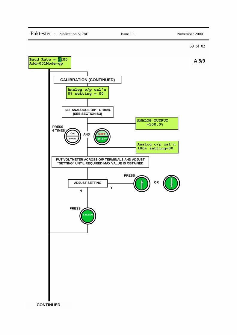
SET ANALOGUE O/P TO 0% (SEE SECTION 5/3)
SELECT
SHIFT AND
Analog o/p cal’n 0% setting=00
PRESS
OR ADJUST SETTING
N Y
ANALOG OUTPUT =000.0%
PUT VOLTMETER ACROSS O/P TERMINALS AND ADJUST “SETTING” UNTIL REQUIRED ZERO VALUE IS OBTAINED
59 of 82
Paktester - Publication S178E Issue 1.1 November 2000
Baud Rate = 1200 Add=001Mode=gp
CALIBRATION (CONTINUED)
A 5/9
CONTINUED
PROG
CAL
PRESS 6 TIMES
SET ANALOGUE O/P TO 100% (SEE SECTION 5/3)
SELECT
SHIFT AND
Analog o/p cal’n 100% setting=00
PRESS
OR ADJUST SETTING
N Y
ANALOG OUTPUT =100.0%
PUT VOLTMETER ACROSS O/P TERMINALS AND ADJUST “SETTING” UNTIL REQUIRED MAX VALUE IS OBTAINED
Analog o/p cal’n 0% setting = 00
PRESS
SYSTEM

60 of 82
Paktester - Publication S178E Issue 1.1 November 2000
Baud Rate = 1200 Add=001Mode=gp
DIAGNOSTIC DATA
Block00 Param00 = 0002 hex
A 5/10
Baud Rate = 1200 Add=001Mode=gp
BLOCK & PARAMETER INFORMATION
AND
SELECT
SHIFT PRESS FIELD
STATUS
PRESS OR
Y
N
THEN
Y
N
SELECT
SHIFT OR PRESS SELECT CORRECT PARAMETER (IF NECESSARY)
SELECT CORRECT BLOCK (IF NECESSARY)
Latest changed data=0000 Blk04
MOST RECENTLY REPORTED EXCEPTION DATA
AND
SELECT
SHIFT PRESS FIELD
STATUS
RETURN TO MAIN DISPLAY
SYSTEM STATUS

61 of 82
Paktester - Publication S178E Issue 1.1 November 2000
A 6/1 PAKTESTER OPTIONS – PAKSCAN 2 (IQ ANALOGUE CARD)
SWITCH ON
Select protocol Pakscan 2
FIELD TEST UNIT PAK (1,2) V5.1
SYSTEM STATUS
Baud Rate = 1200 Add=001Mode=iqa
OR Y
N
Baud Rate = 1200 Add=001Mode=iqa
PRESS
OPTIONS
RE-PROGRAMMING
CALIBRATION
CONTINUED
INTERROGATION
DIAGNOSTIC DATA
SELECT CORRECT BAUD RATE (IF NECESSARY)

62 of 82
Paktester - Publication S178E Issue 1.1 November 2000
Baud Rate = 1200 Add=001Mode=iqa
PRESS
CONTINUED
INTERROGATION
ALARM DISPLAY
FIELD ALARMS
Position Display Meaning 1-11 (Not used) 12 F Memory fault 13 W Watchdog 14 P Power on reset 15 (reserved) 16 L (flashing) Loopback on
ALARM ACCEPT
PRESS
TO ACCEPT ALARM
FIELD STATUS
FIELD STATUS
PRESS
P L FIELD ALARMS A
A 6/2
ANALOG INPUTS(%) A=000.0 B=000.0

63 of 82
Paktester - Publication S178E Issue 1.1 November 2000
Baud Rate = 1200 Add=001Mode=gp
RE-PROGRAMMING
PRESS
New B/Rate =1200 & Address =001
PROG
CAL
OR
Y
N
THEN
Y
N
SELECT
SHIFT OR PRESS
PRESS
PROG
CAL PRESS
AIN 1 time =005s & deadband =01%
A 6/3
CONTINUED
CONTINUED
SELECT NEW ADDRESS (IF NECESSARY)
SELECT NEW BAUD RATE (IF NECESSARY)
PRESS OR
Y
N
TO CHANGE ANALOGUE I/P1 REPORT TIMEOUT
THEN
Y
N
SELECT
SHIFT OR PRESS TO MODIFY ANALOGUE I/P1 DEADBAND

64 of 82
Paktester - Publication S178E Issue 1.1 November 2000
Baud Rate = 1200 Add=001Mode=gp
RE-PROGRAMMING (CONTINUED)
PRESS
AIN 2 time =005s & deadband =01%
PROG
CAL
OR
Y
N
THEN
Y
N
SELECT
SHIFT OR PRESS
PRESS
PROG
CAL PRESS
AIN 1 Mode =mA AIN 2 Mode =mA
A 6/4
CONTINUED
CONTINUED
TO MODIFY ANALOGUE I/P2 DEADBAND
TO CHANGE ANALOGUE I/P2 REPORT TIMEOUT
PRESS OR
Y
N
TO CHANGE ANALOGUE I/P1 SOURCE (CURRENT OR VOLTS)
THEN
Y
N
SELECT
SHIFT OR PRESS TO CHANGE ANALOGUE I/P1 SOURCE (CURRENT OR VOLTS)
AIN 1 time =005s & deadband =01%

65 of 82
Paktester - Publication S178E Issue 1.1 November 2000
Baud Rate = 1200 Add=001Mode=pos A 6/5
CONTINUED
PRESS
PRESS
Press & to program values
PLEASE WAIT PROGRAMMING
Press & to program values
PROG
CAL
SWITCH PAKTESTER OFF & ON & CHECK THAT PARAMETERS HAVE BEEN CORRECTLY PROGRAMMED
AND
RE-PROGRAMMING (CONTINUED)
AIN 1 Mode =mA AIN 2 Mode =mA
CALIBRATION
PROG
CAL PRESS
SET ANALOGUE 1 I/P TO 0%
SELECT
SHIFT AND
Press & to set analog1 0% I/P
PRESS
AND PROGRAM NEW ANALOGUE 1 0% VALUE
Y N
CONTINUED

66 of 82
Paktester - Publication S178E Issue 1.1 November 2000
Baud Rate = 1200 Add=001Mode=iqa
CALIBRATION (CONTINUED)
A 6/6
CONTINUED
Press & to set analog1 0% I/P
PROG
CAL PRESS
SET ANALOGUE 1 I/P TO 100%
SELECT
SHIFT AND
Press & to set analog1 100% I/P
PROG
CAL PRESS
SET ANALOGUE 2 I/P TO 0%
SELECT
SHIFT AND
Press & to set analog2 0% I/P
PRESS
AND PROGRAM NEW ANALOGUE 1 100% VALUE
N Y
PRESS
AND PROGRAM NEW ANALOGUE 2 0% VALUE
N Y
SYSTEM STATUS
PRESS
PROG
CAL PRESS
SET ANALOGUE 2 I/P TO 100%
SELECT
SHIFT AND
Press & to set analog2 0% I/P
PRESS
AND PROGRAM NEW ANALOGUE 2 100% VALUE
N Y

67 of 82
Paktester - Publication S178E Issue 1.1 November 2000
Baud Rate = 1200 Add=001Mode=iqa
DIAGNOSTIC DATA
Block00 Param00 = 0002 hex
A 6/7
Baud Rate = 1200 Add=001Mode=iqa
BLOCK & PARAMETER INFORMATION
AND
SELECT
SHIFT PRESS FIELD
STATUS
PRESS OR
Y
N
THEN
Y
N
SELECT
SHIFT OR PRESS SELECT CORRECT PARAMETER (IF NECESSARY)
SELECT CORRECT BLOCK (IF NECESSARY)
Latest changed data=0000 Blk04
MOST RECENTLY REPORTED EXCEPTION DATA
AND
SELECT
SHIFT PRESS FIELD
STATUS
RETURN TO MAIN DISPLAY
SYSTEM STATUS

68 of 82
Paktester - Publication S178E Issue 1.1 November 2000
A 7/1 PAKTESTER OPTIONS – PAKSCAN 2 (FLOWPAK ACTUATOR FCU’S)
SWITCH ON
Select protocol Pakscan 2
FIELD TEST UNIT PAK (1,2) V5.1
SYSTEM STATUS
Baud Rate = 1200 Add=001Mode=dig
OR Y
N
THEN Y
N
Baud Rate = 1200 Add=001Mode=dig
PRESS
PRESS TWICE
OPTIONS
OPERATION
RE-PROGRAMMING
CONTINUED
INTERROGATION
SELECT
SHIFT
DIAGNOSTIC DATA
SELECT CORRECT BAUD RATE (IF NECESSARY)
SELECT CORRECT MODE (IF NECESSARY)

69 of 82
Paktester - Publication S178E Issue 1.1 November 2000
Baud Rate = 1200 Add=001Mode=dig
PRESS
OPERATION
CONTINUED
INTERROGATION
ALARM DISPLAY
FIELD ALARMS
ALARM ACCEPT
PRESS
TO ACCEPT ALARM
FIELD STATUS
FIELD STATUS
PRESS
OA=0 OT=0 I1=0 CA=1 CT=0 I4=0
OA=0 OT=0 DVddd CA=1 CT=0 MVmmm
RL S M L FIELD ALARMS A
DIGITAL (TYPE 1)
POSITIONAL (TYPE 3)
CLOSE (RLY1)
NOT
STOP (RLY3)
NOT
OPEN (RLY2)
NOT NOT
ESD (RLY4)
OPEN STOP CLOSE ESD
A 7/2
Position Display Meaning 1 R Relay (monitor) 2 L Local stop 3 T Low pressure 4 C Control not available 5 (reserved) 6 S Start / stop fail 7 J Jammed valve 8 O Obstructed valve 9 E End of travel / stop fail 10 M Manual operation 11 (reserved) 12 F Memory fault 13 W Watchdog 14 P Power on reset 15 (reserved) 16 L (flashing) Loopback on
Code Description
OA Open Limit Switch
CA Closed Limit Switch
OT Open Torque Limit Switch – Pak 1 only
CT Close Torque Limit Switch – Pak 1 only
I1 Motor Stopped (Between limits)
I4 Motor Running
DV Desired Value
MV Measured Value

70 of 82
Paktester - Publication S178E Issue 1.1 November 2000
Baud Rate = 1200 Add=001Mode=dig
RE-PROGRAMMING
PRESS
New B/Rate =1200 & Address =001
PROG
CAL
OR
Y
N
THEN
Y
N
SELECT
SHIFT OR PRESS
PRESS
PRESS OR
Y
N
THEN
Y
N
SELECT
SHIFT OR PRESS
PROG
CAL PRESS
New MITime =001s & deadband =01%
A 7/3
CONTINUED
SELECT NEW ADDRESS (IF NECESSARY)
SELECT NEW BAUD RATE (IF NECESSARY)
SELECT NEW M.I.T. (IF NECESSARY)
SELECT NEW DEADBAND (IF NECESSARY)
CONTINUED
71 of 82
Paktester - Publication S178E Issue 1.1 November 2000
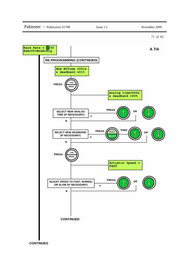
Baud Rate = 1200 Add=001Mode=dig
RE-PROGRAMMING (CONTINUED)
A 7/4
CONTINUED
PRESS OR
Y
N
THEN
Y
N
SELECT
SHIFT OR PRESS
Analog time=000s & deadband =00%
SELECT NEW ANALOG TIME (IF NECESSARY)
SELECT NEW DEADBAND (IF NECESSARY)
CONTINUED
New MITime =001s & deadband =01%
PROG
CAL PRESS
PRESS OR
Y
N
Actuator Speed = FAST
ADJUST SPEED TO FAST, NORMAL OR SLOW (IF NECESSARY)
PROG
CAL PRESS

72 of 82
Paktester - Publication S178E Issue 1.1 November 2000
Baud Rate = 1200 Add=001Mode=dig
RE-PROGRAMMING (CONTINUED)
PRESS
Manual release pulse = 50
PROG
CAL
OR
Y
N
PROG
CAL
PRESS
PRESS
PRESS
AND
Press & to program values
PLEASE WAIT PROGRAMMING
SWITCH PAKTESTER OFF & ON & CHECK THAT PARAMETERS HAVE BEEN CORRECTLY PROGRAMMED
Press & to program values
A 7/5
CONTINUED
SELECT NEW RELEASE PULSE TIME (IF NECESSARY)
Actuator Speed = FAST

73 of 82
Paktester - Publication S178E Issue 1.1 November 2000
Baud Rate = 1200 Add=001Mode=dig
DIAGNOSTIC DATA
Block00 Param00 = 0002 hex
A 7/6
Baud Rate = 1200 Add=001Mode=dig
BLOCK & PARAMETER INFORMATION
AND
SELECT
SHIFT PRESS FIELD
STATUS
PRESS OR
Y
N
THEN
Y
N
SELECT
SHIFT OR PRESS SELECT CORRECT PARAMETER (IF NECESSARY)
SELECT CORRECT BLOCK (IF NECESSARY)
Latest changed data=0000 Blk04
MOST RECENTLY REPORTED EXCEPTION DATA
AND
SELECT
SHIFT PRESS FIELD
STATUS
RETURN TO MAIN DISPLAY
SYSTEM STATUS
74 of 82
Paktester - Publication S178E Issue 1.1 November 2000
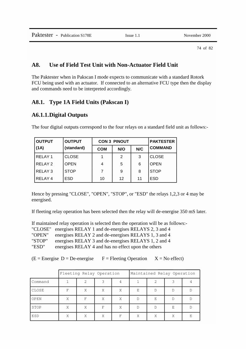
A8. Use of Field Test Unit with Non-Actuator Field Unit The Paktester when in Pakscan I mode expects to communicate with a standard Rotork FCU being used with an actuator. If connected to an alternative FCU type then the display and commands need to be interpreted accordingly. A8.1. Type 1A Field Units (Pakscan I) A6.1.1. Digital Outputs The four digital outputs correspond to the four relays on a standard field unit as follows:-
Hence by pressing "CLOSE", "OPEN", "STOP", or "ESD" the relays 1,2,3 or 4 may be energised. If fleeting relay operation has been selected then the relay will de-energise 350 mS later. If maintained relay operation is selected then the operation will be as follows:- "CLOSE" energises RELAY 1 and de-energises RELAYS 2, 3 and 4 "OPEN" energises RELAY 2 and de-energises RELAYS 1, 3 and 4 "STOP" energises RELAY 3 and de-energises RELAYS 1, 2 and 4 "ESD" energises RELAY 4 and has no effect upon the others (E = Energise D = De-energise F = Fleeting Operation X = No effect)
OUTPUT OUTPUT CON 3 PINOUT PAKTESTER
(1A) (standard) COM N/O N/C COMMAND
RELAY 1 CLOSE 1 2 3 CLOSE
RELAY 2 OPEN 4 5 6 OPEN
RELAY 3 STOP 7 9 8 STOP
RELAY 4 ESD 10 12 11 ESD
Fleeting Relay Operation
Command 1 2 3 4 1 2 3 4
CLOSE F X X X E D D D
OPEN X F X X D E D D
STOP X X F X D D E D
ESD X X X F X X X E
Maintained Relay Operation

75 of 82
Paktester - Publication S178E Issue 1.1 November 2000
A8.1.2. Digital Inputs Ten digital inputs are available on a type 1A Field Unit. These are transmitted to the FCU and interpreted by the Paktester as ordinary actuator status bits. The following table shows the relationship between the 1A digital inputs, the standard FCU digital inputs and how the data is displayed at the FCU.
All inputs are active high (+5V) or normally closed contacts, (i.e. open circuit input is active) A8.1.3. Analogue Input The analogue input may be monitored by selecting "MODE = ANG" on the Paktester SYSTEM STATUS display. The unit will now indicate a value between 0 and 255 on the FIELD STATUS display which corresponds to an input of between 0% and 100% of a 5V reference. If current inputs are being used this corresponds to a nominal full scale input of 0 to 20.8mA.
1A Digital Standard FCU Con 2 Paktester display for Digital I/P Pin Nr Input Active Input Inactive
Input 0 OTLS 1 OTLS = 1 OTLS = 0
Input 1 CTLS 2 CTLS = 1 CTLS = 0
Input 2 OAS 3 OAS = 1 OAS = 0
Input 3 CAS 4 CAS = 1 CAS = 0
Input 4 IAS1 5 IAS1 = 1 IAS1 = 0
Input 5 IAS4 6 IAS4 = 1 IAS4 = 0
Input 6 MR 7 OAS status flashing OAS status steady
Input 7 CNA 8 CAS status flashing CAS status steady
Input 8 MON 9 No indication No indication
Input 9 LSTOP 11 No indication No indication
Common 12
76 of 82
Paktester - Publication S178E Issue 1.1 November 2000
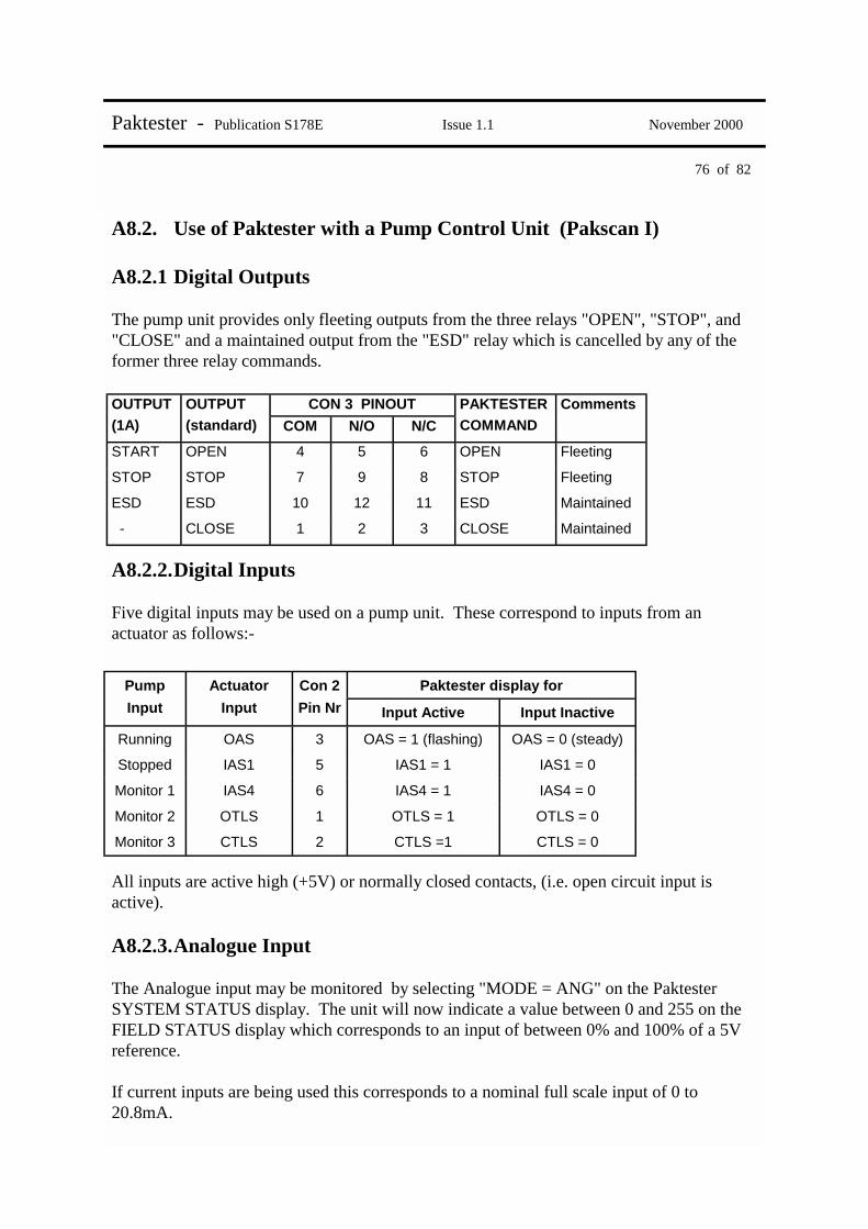
A8.2. Use of Paktester with a Pump Control Unit (Pakscan I) A8.2.1 Digital Outputs The pump unit provides only fleeting outputs from the three relays "OPEN", "STOP", and "CLOSE" and a maintained output from the "ESD" relay which is cancelled by any of the former three relay commands.
A8.2.2. Digital Inputs Five digital inputs may be used on a pump unit. These correspond to inputs from an actuator as follows:-
All inputs are active high (+5V) or normally closed contacts, (i.e. open circuit input is active). A8.2.3. Analogue Input The Analogue input may be monitored by selecting "MODE = ANG" on the Paktester SYSTEM STATUS display. The unit will now indicate a value between 0 and 255 on the FIELD STATUS display which corresponds to an input of between 0% and 100% of a 5V reference. If current inputs are being used this corresponds to a nominal full scale input of 0 to 20.8mA.
OUTPUT OUTPUT PAKTESTER Comments
(1A) (standard) COM N/O N/C COMMAND
START OPEN 4 5 6 OPEN Fleeting
STOP STOP 7 9 8 STOP Fleeting
ESD ESD 10 12 11 ESD Maintained
- CLOSE 1 2 3 CLOSE Maintained
CON 3 PINOUT
Pump Actuator Con 2 Paktester display for Input Input Pin Nr Input Active Input Inactive
Running OAS 3 OAS = 1 (flashing) OAS = 0 (steady)
Stopped IAS1 5 IAS1 = 1 IAS1 = 0
Monitor 1 IAS4 6 IAS4 = 1 IAS4 = 0
Monitor 2 OTLS 1 OTLS = 1 OTLS = 0
Monitor 3 CTLS 2 CTLS =1 CTLS = 0

77 of 82
Paktester - Publication S178E Issue 1.1 November 2000
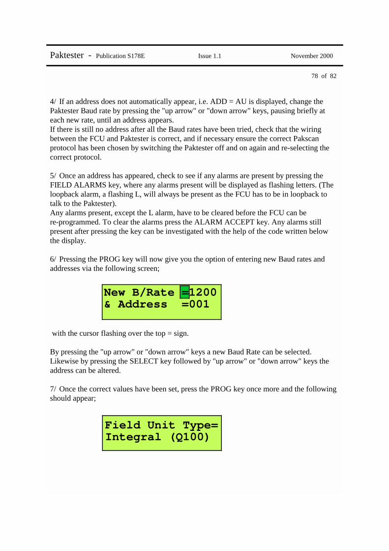
A9 Programming example This example is based upon re-programming a type 1 Pakscan II, or IIE, Integral Field Unit. 1/ Connect your Paktester to the correct 2 wire loop terminals as shown in fig 1 on page 6. 2/ Switch on the Paktester and the following display should briefly appear; (Check that the version of software shown is V5.0 or higher) followed by; with the cursor flashing over the 2 indicating Pakscan II. Ensure that the protocol displayed is correct for the Field Unit with which you are communicating. (The protocol can be altered between I and II by using either the "up arrow" or "down arrow" key). 3/ Once the correct protocol has been selected press the SYSTEM STATUS key and the display will now show; with the cursor flashing over the "1" in the 1200. (The address displayed will either be the address last programmed into the Field Unit or ADD = AU will appear)
FIELD TEST UNIT PAK (1,2) V5.1
Select protocol Pakscan 2
Baud Rate = 1200 Add=001Mode=dig
78 of 82
Paktester - Publication S178E Issue 1.1 November 2000
4/ If an address does not automatically appear, i.e. ADD = AU is displayed, change the Paktester Baud rate by pressing the "up arrow" or "down arrow" keys, pausing briefly at each new rate, until an address appears. If there is still no address after all the Baud rates have been tried, check that the wiring between the FCU and Paktester is correct, and if necessary ensure the correct Pakscan protocol has been chosen by switching the Paktester off and on again and re-selecting the correct protocol. 5/ Once an address has appeared, check to see if any alarms are present by pressing the FIELD ALARMS key, where any alarms present will be displayed as flashing letters. (The loopback alarm, a flashing L, will always be present as the FCU has to be in loopback to talk to the Paktester). Any alarms present, except the L alarm, have to be cleared before the FCU can be re-programmed. To clear the alarms press the ALARM ACCEPT key. Any alarms still present after pressing the key can be investigated with the help of the code written below the display. 6/ Pressing the PROG key will now give you the option of entering new Baud rates and addresses via the following screen; with the cursor flashing over the top = sign. By pressing the "up arrow" or "down arrow" keys a new Baud Rate can be selected. Likewise by pressing the SELECT key followed by "up arrow" or "down arrow" keys the address can be altered. 7/ Once the correct values have been set, press the PROG key once more and the following should appear;
New B/Rate =1200 & Address =001
Field Unit Type= Integral (Q100)

79 of 82
Paktester - Publication S178E Issue 1.1 November 2000
8/ Press the PROG key again and the following instruction will be displayed; Press the "up arrow" and "down arrow" keys together, and the following message will then briefly appear. followed by; 9/ Turn the Paktester off and then on again. Then follow steps 1 to 4 to prove that the new address and/or baud rate have been successfully re-programmed.
Press & to program values
PLEASE WAIT PROGRAMMING
Press & to program values

80 of 82
Paktester - Publication S178E Issue 1.1 November 2000
A10 Auxiliary I/P Mask setting for an IQ The bits AUX1 - 8 can be thought of in the following way;
However, on the Paktester the mask will appear in the form;
If AUX1 - 4 are to be used for remote I/P’s they have already been designated as follows; AUX1 - OPEN AUX2 - CLOSE AUX3 - STOP / MAINTAIN AUX4 - ESD Rules: 1/ Function bit set to 0 - Any function bit set to a “0” indicates that the particular aux I/P is to be treated as a digital signal to be passed on to the master station. - If the corresponding invert bit is set to a “0”, the signal is inverted before being passed on to the master station. - If the corresponding invert bit is set to a “1”, the signal is not inverted before being passed on to the master station. 2/ Function bit set to 1 - Any function bit set to a “1” indicates that the particular aux I/P is to be treated as a digital command to operate the actuator. The command signal will also be passed on to the master station - When the corresponding invert bit is set to a “0”, this represents a N.C. contact as being the command source, i.e. an open contact generates a command. - When the corresponding invert bit is set to a “1”, this represents a N.O. contact as being the command source, i.e. a closed contact generates a command.
AUX4 – 1 (Invert)
Bits 8 7 6 5 4 3 2 1
X X X X X X X X
AUX4 – 1 (Function)
AUX4> X X X X <1 This line corresponds to bits 8 – 5, i.e. Function
X X X X This line corresponds to bits 4 – 1, i.e. Invert

81 of 82
Paktester - Publication S178E Issue 1.1 November 2000
3/ Standard hard-wiring ESD condition - When used with an option card, such as Pakscan, the auxiliary inputs should not be wired as shown in the “remote control circuits” (form A to F). This is because both the control type (push to run or maintained) and input (N.O. or N.C.) are determined by the auxiliary input mask - When using ESD (aux I/P 4) the ESD contact mode setting on the IQ (A3) should be set to the default value of “NO”. The A1 - ESD enable setting should be “ON” and the A2 - ESD direction should be set to either open or close Examples Example 1: AUX1 - 4 are to be used to feed digital information over the 2 wire loop to the host, via the master station. Inputs 2 and 3 need to be inverted to give a “1” to the host when the actual input is a “0”.
Example 2: AUX1 - 4 are to be used as remote I/P’s to control the actuator. The OPEN, CLOSE and ESD I/P’s are NO and the STOP/MAINTAIN I/P is NC
Note: With the Stop / Maintain line set to 0, the OPEN, CLOSE and ESD commands are “maintained”. If the Stop / Maintain were set to 1 the OPEN, CLOSE and ESD commands would be “push to run”, i.e. the actuator will stop when the input is de-energised. Example 3: AUX1 - 2 are to be used as remote I/P’s to OPEN and CLOSE the actuator. The OPEN and CLOSE I/P’s are NO. AUX3 - 4 are to be used to feed digital information, which needs to be inverted, to the host.
Note: With this option the open and close commands are maintained. For further information on the IQ mask, see the “Remote Auxiliary Input Mask” section in the IQ Field Unit Manual S172E.
Aux 4> 0 0 0 0 <1 IQ setting tool option
1 0 0 1 PF = 09
Aux 4> 1 1 1 1 <1 IQ setting tool option
1 0 1 1 PF = FB
Aux 4> 0 0 1 1 <1 IQ setting tool option
0 0 1 1 PF = 33

82 of 82
Paktester - Publication S178E Issue 1.1 November 2000
Rotork Controls Ltd Rotork Controls Inc Bath, England. 675 Mile Crossing Blvd, BA1 3JQ Rochester, tel: (01225) 428451 New York 14624, fax: (01225) 333467 USA tel: (716) 328 1550 fax: (716) 328 5848