pages from chapter 17 keys and key ways chapter 18 worked examples in machine...
TRANSCRIPT

8/14/2019 Pages From Chapter 17 Keys and Key Ways Chapter 18 Worked Examples in Machine Drawing-Ae57fc4652ea5c33…
http://slidepdf.com/reader/full/pages-from-chapter-17-keys-and-key-ways-chapter-18-worked-examples-in-machine 1/4
http://www.download-it.org/learning-resources.php?promoCode=&partnerID=&content=story&storyID=19975
Chapter 17
Keys and key waysA key, Fig. 17.1 , is usually made from steel and is insertedbetween the joint of two parts to prevent relative movement;it is also inserted between a shaft and a hub in an axialdirection, to prevent relative rotation. A keyway, Figs.17.2, 17.3 and 17.4 , is a recess in a shaft or hub to receivea key, and these recesses are commonly cut on key-seatingmachines or by broaching, milling, planning, shaping andslotting. The proportions of cross-sections of keys vary with
the shaft size, and reference should be made to BS 4235 forthe exact dimensions. The length of the key controls the areaof the cross-section subject to shear, and will need to becalculated from the knowledge of the forces being transmit-ted or, in the case of feather keys, the additional informationof the length of axial movement required.
Sunk keys
Examples of sunk keys are shown in Fig. 17.5 , where the keyis sunk into the shaft for halfits thickness. This measurement
FIGURE 17.4 Keyway in hub.
FIGURE 17.2 Edge-milled keyway.
Squareparallel key
Round-endparallel key
Gib-head key
FIGURE 17.1
FIGURE 17.3 End-milled keyway.
W
T
Rectangular key
W
D = Shaft diameter
W =D4
T =D6
φ D
Square key
W 2
W 2
T 2
T 2
FIGURE 17.5
Manual of Engineering DrawingCopyright 2009 Elsevier Ltd. All rights of reproduction in any form reserved. 131
Buy this file: http://www.download-it.org/learning-resources.php?promoCode=&partnerID=&content=story&storyID=19975
8/14/2019 Pages From Chapter 17 Keys and Key Ways Chapter 18 Worked Examples in Machine Drawing-Ae57fc4652ea5c33…
http://slidepdf.com/reader/full/pages-from-chapter-17-keys-and-key-ways-chapter-18-worked-examples-in-machine 2/4
http://www.download-it.org/learning-resources.php?promoCode=&partnerID=&content=story&storyID=19975
is taken at the side of the key, and not along the centre linethrough the shaft axis. Figure 17.5 shows useful proportionsused for assembly drawings.
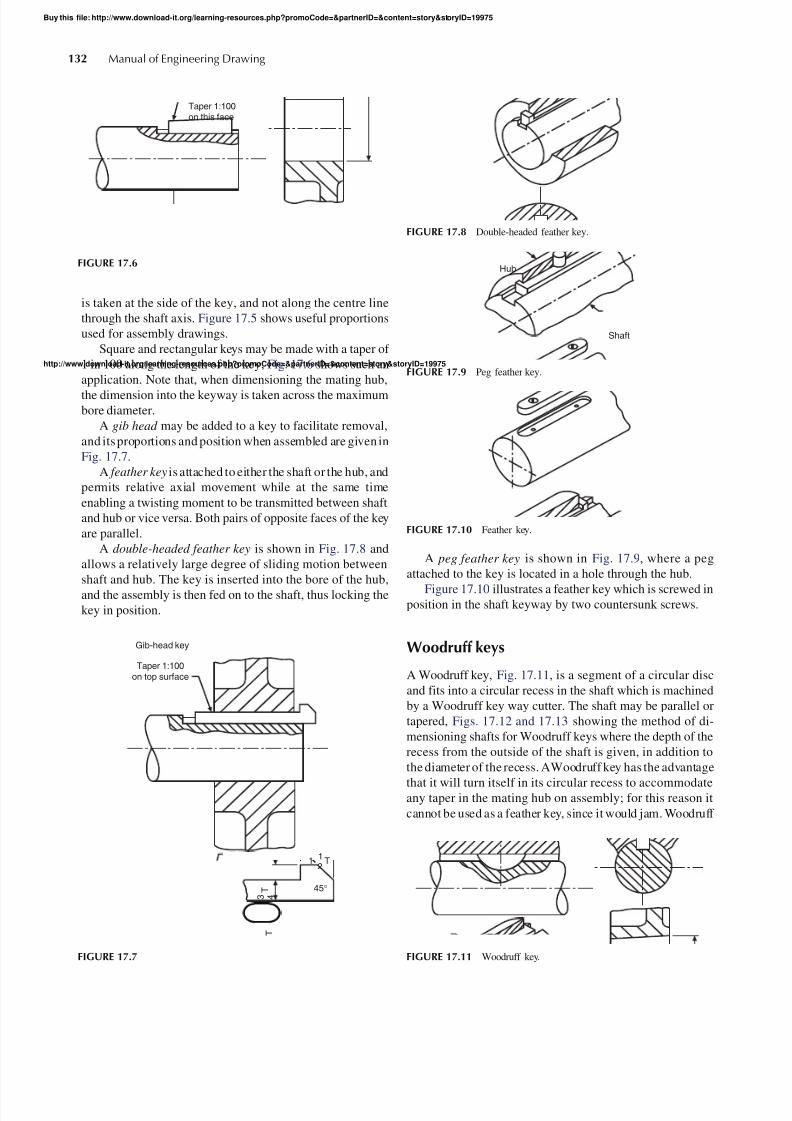
Square and rectangular keys may be made with a taper of 1 in 100 along the length of the key; Fig. 17.6 shows such anapplication. Note that, when dimensioning the mating hub,the dimension into the keyway is taken across the maximumbore diameter.
A gib head may be added to a key to facilitate removal,and its proportions and position when assembled are given inFig. 17.7 .
A feather key is attached to either the shaft or the hub, andpermits relative axial movement while at the same timeenabling a twisting moment to be transmitted between shaftand hub or vice versa. Both pairs of opposite faces of the keyare parallel.
A double-headed feather key is shown in Fig. 17.8 andallows a relatively large degree of sliding motion betweenshaft and hub. The key is inserted into the bore of the hub,and the assembly is then fed on to the shaft, thus locking thekey in position.
A peg feather key is shown in Fig. 17.9 , where a pegattached to the key is located in a hole through the hub.
Figure 17.10 illustrates a feather key which is screwed inposition in the shaft keyway by two countersunk screws.
Woodruff keys
A Woodruff key, Fig. 17.11 , is a segment of a circular discand fits into a circular recess in the shaft which is machinedby a Woodruff key way cutter. The shaft may be parallel ortapered, Figs. 17.12 and 17.13 showing the method of di-mensioning shafts for Woodruff keys where the depth of therecess from the outside of the shaft is given, in addition tothe diameter of the recess. AWoodruff key has the advantage
that it will turn itself in its circular recess to accommodateany taper in the mating hub on assembly; for this reason itcannot be used as a feather key, since it would jam. Woodruff
Taper 1:100on top surface
Gib-head key
112
T
45 °
3 4 T
T
FIGURE 17.7
FIGURE 17.8 Double-headed feather key.
Shaft
Hub
FIGURE 17.9 Peg feather key.
FIGURE 17.11 Woodruff key.
Taper 1:100on this face
FIGURE 17.6
FIGURE 17.10 Feather key.
Manual of Engineering Drawing132
Buy this file: http://www.download-it.org/learning-resources.php?promoCode=&partnerID=&content=story&storyID=19975

8/14/2019 Pages From Chapter 17 Keys and Key Ways Chapter 18 Worked Examples in Machine Drawing-Ae57fc4652ea5c33…
http://slidepdf.com/reader/full/pages-from-chapter-17-keys-and-key-ways-chapter-18-worked-examples-in-machine 3/4
http://www.download-it.org/learning-resources.php?promoCode=&partnerID=&content=story&storyID=19975
keys are commonly used in machine tools and, for example,between the flywheel and the crankshaft of a small internal-combustion engine where the drive depends largely on the fitbetween the shaft and the conically bored flywheel hub. Thedeep recess fora Woodruff key weakens theshaft, but there is
little tendency for the key to turn over when in use.Where lighter loads are transmitted and the cost of cut-
ting a keyway is not justified, round keys and flat or hollowsaddle keys as shown in Fig. 17.14 can be used.
Saddle keys are essentially for light duty only, overload-ing tending to make them rock and work loose on the shaft.Both flat and hollow saddle keys may have a taper of 1 in 100on the face in contact with the hub. The round key may either
be tapered or, on assembly, the end of the shaft and hub maybe tapped after drilling anda special threaded key be screwedin to secure the components.
Dimensioning keyways (parallel keys)
The method of dimensioning a parallel shaft is shown inFig. 17.15 , and a parallel hub in Fig. 17.16 . Note that in eachcase it is, essential to showthe dimension to the bottom of thekeyway measured across the diameter of the shaft and thebore of the hub. This practice cannot be used where, eitherthe shaft or hub is tapered, and Fig. 17.17 shows the method
FIGURE 17.17 Keyway for square or rectangular parallel key in taperedshaft.
φ d
φ D
T T
W W
Hollowsaddle key
Flatsaddle key
Round key
T =W3
W =D4
d = D6
FIGURE 17.14
B
A
FIGURE 17.13 Dimensions required for a Woodruff key in a taperedshaft.
BA
FIGURE 17.12 Dimensions required for a Woodruff key in a parallelshaft.
FIGURE 17.15 Keyway in parallel shaft.
FIGURE 17.16 Keyway in parallel hub.
Chapter | 17 Keys and key ways 133
Buy this file: http://www.download-it.org/learning-resources.php?promoCode=&partnerID=&content=story&storyID=19975

8/14/2019 Pages From Chapter 17 Keys and Key Ways Chapter 18 Worked Examples in Machine Drawing-Ae57fc4652ea5c33…
http://slidepdf.com/reader/full/pages-from-chapter-17-keys-and-key-ways-chapter-18-worked-examples-in-machine 4/4
The publisher detailed in the title page holds the copyright for this document
All rights reserved. No part of this publication may be reproduced, stored in a retrieval system, or transmitted,in any form or by any means, electronic, mechanical, photocopying, recorded or otherwise, without the writtenpermission of Spenford IT Ltd who are licensed to reproduce this document by thepublisher
All requests should by sent in the first instance to
Please ensure you have book-marked our website.
www.download-it.org
Chapter extract
To buy the full file, and for copyright
information, click herehttp://www.download-it.org/learning-resources.php?promoCode=&partnerID=&content=story&storyID=19975