page 1 of 32 ph09 unitpacket2014key - yolanotes 2: ohm’s law and power 5. ... page 6 of 32...
TRANSCRIPT

Page 1 of 32 Ph09_UnitPacket2014Key

Page 2 of 32 Ph09_UnitPacket2014Key
Unit Packet Contents
1. Notes 1: Flowing Charges
2. Concept Development: Electric Current
3. Guided Practice: Current & Resistance
4. Notes 2: Ohm’s Law and Power
5. Concept Development: Ohm’s Law & Power
6. Guided Practice: Ohm’s Law and Power
7. Notes 3: Series and Parallel Circuits
8. Guided Practice: Series and Parallel Circuits
9. Notes 4: Combination Circuits
10. Guided Practice: Combination Circuits
11. Independent Practice: Combination Circuits
Textbook Assignments:
1. Due Monday 4/7 Read pages 531 – 544
Do page 545
Review Questions 1-17, 23-25
Plug and Chug 26-29
2. Due Friday 4/25
Read pages 548 – 558
Do page 559
Review Questions 1-15
Think and Explain 20-22

Page 3 of 32 Ph09_UnitPacket2014Key
Name__________________________ Regents Physics
Date_____________________
Notes: Flowing charges
Objectives:
1. Define electric current and state its SI unit.
2. Solve problems involving current, charge and time.
3. Distinguish between conventional current and electron flow.
4. Solve problems that relate current, potenital difference and resistance.
Flow of Electric Charge
Water will spontaneously flow from a reservoir of ______________________ to a reservoir of
____________________
Similarly electric charges will spontaneously flow from a place of ________________ potential to a place of
________________ potential they can do work.
Consider two oppositely charged plates:
An electron has higher potential energy at the negatively charged plate and can ____________________ as it
falls from the place of higher potential to the place of lower potential.
Providing a ______________________ for the charge to flow through makes it possible to harness the work
the charge can do.
Electric current is the quantity of ____________________through a cross section of a conductor
per__________________.
+
+ +
+
+ +
-
- -
-
-
Place of _______ potential for electrons
Place of __________ potential for electrons
-
- -
-
higher
lower higher
lower
do work
coducting wire
electric charge
unit time
higher pressure
lower pressure

Page 4 of 32 Ph09_UnitPacket2014Key
In the language of mathematics:
t
qI
Example problem: If a conductor has a current of 1 ampere flowing through it, how many electrons are flowing
per second?
Example problem What is the electric current in a conductor if 240 coulombs of charge pass through it in 1.0
minute?
Current and Potential Difference
Very often when charge is flowing it is the result of flow of __________________
Charge may also flow as a result of _________________________ flowing
Consider a positive and negative charge with a potential difference
By convention current is considered to flow in the direction of ______________________ in elecric circuits.
(Opposite direction of __________________)
I = current (amperes = coulomb/second) Q = charge (coulomb) t = time (seconds)
+
Direction of electron flow
Flow of ____________ charges
electrons
charged ions
positive charges
electrons
positive

Page 5 of 32 Ph09_UnitPacket2014Key
Sources of electrical energy
Batteries -- Chemical reactions cause _______________________ with a potential difference.
Electrons spontaneously flow from ___________________ to ______________________.
Generators -- Mechanical energy in a ______________________ is converted to an electrical potential
difference.
Resistance to Charge Flow
Water being pumped through a hose may experience resistance due to ________________ if it were forced
to travel through a zig-zag hose.
Flowing electric charges usually do work because of _______________________ that they experience when
trying to flow.
Ex: Electrons flowing through a ________________________ have lots of collisions with atoms, make
them hot until they glow. (incandescent light)
Resistance for a given piece of wire depends on the:
o ________________ of the wire; A longer wire has _________________ resistance.
o ________________ of the wire: a fatter wire has ___________ resistance.
o __________________ of the wire; a hotter wire has ____________ resistance.
o the __________________ of the material that the wire is made of; e.g. gold is a better conductor
than ____________________
The resistance of a given piece of wire at a given temperature is given by:
resistance
tungston wire
negative pole positive pole
charged poles
magnetic field
friction
length greater
diameter greater
temperature greater
properties
aluminum
A
LR
ρ = Resistivity: property of the material (see reference tables) L = Length of the wire
A = Cross Sectional Area of wire
A L
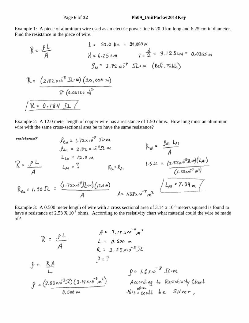
Page 6 of 32 Ph09_UnitPacket2014Key
Example 1: A piece of aluminum wire used as an electric power line is 20.0 km long and 6.25 cm in diameter.
Find the resistance in the piece of wire.
Example 2: A 12.0 meter length of copper wire has a resistance of 1.50 ohms. How long must an aluminum
wire with the same cross-sectional area be to have the same resistance?
Example 3: A 0.500 meter length of wire with a cross sectional area of 3.14 x 10⁻⁶ meters squared is found to
have a resistance of 2.53 X 10⁻³ ohms. According to the resistivity chart what material could the wire be made
of?

Page 7 of 32 Ph09_UnitPacket2014Key
Name ______________________ Regents / Honors Physics
Date ____________
Guided Practice: Current and Resistance

Page 8 of 32 Ph09_UnitPacket2014Key

Page 9 of 32 Ph09_UnitPacket2014Key

Page 10 of 32 Ph09_UnitPacket2014Key

Page 11 of 32 Ph09_UnitPacket2014Key

Page 12 of 32 Ph09_UnitPacket2014Key

Page 13 of 32 Ph09_UnitPacket2014Key

Page 14 of 32 Ph09_UnitPacket2014Key

Page 15 of 32 Ph09_UnitPacket2014Key

Page 16 of 32 Ph09_UnitPacket2014Key

Page 17 of 32 Ph09_UnitPacket2014Key

Page 18 of 32 Ph09_UnitPacket2014Key

Page 19 of 32 Ph09_UnitPacket2014Key
Name__________________________ Regents Physics
Date_____________________
Notes: Series and Parallel circuits
1. Define a series circuit and draw circuit diagrams for parallel circuits.
2. Define a parallel circuit and draw circuit diagrams for parallel circuits.
3. State the relationships for parallel circuits and solve problems using these relationships.
4. Compare and contrast series and parallel circuits.
Electrical Circuits
Any path along which electrons may flow is a _______________________
Electric Circuit notation: (See Reference Tables)
Conductors -- Conductors are represented in electric circuits by solid, _________________ and are taken
to be conductors of negligible resistance.
Devices --
Cell – An electrochemical cell that has two ___________________ with a _____________________ for
electrons
Symbol
Battery -- A combination of _______________ cells; is the source of potential difference in the circuit.
Symbol
Resistor -- A device that is made of a relatively ________________________ of electricity. As current
flows through the PE of electrons is converted to heat energy. Results in a drop in ________________
Symbol
Ammeter -- A meter that measures the ___________________ through a circuit or portion of a circuit.
The connections for an ammeter must force the current to flow _________________________ in order to be
measured.
Symbol
Voltmeter -- a meter that measures the _________________________ between two points in a circuit.
circuit
straight lines
electrodes potential difference
2 or more
poor conductor
voltage
current
through the meter
potential difference

Page 20 of 32 Ph09_UnitPacket2014Key
A voltmeter must be connected to the ______________________ in the circuit where the potential difference
is to be measured.
A voltmeter is connected in _______________________
Symbol
A good rule to remember – If a voltmeter is connected so there is only _________ between the points where
the two leads are connected the voltmeter will read ___________
Light bulb -- As electrons flow through and collide with atoms heat is generated until a filament glows
bright.
Symbol
Switch -- Used to interrupt or allow the flow of charge in a circuit.
Symbol
Example 1: Draw a circuit with one 9 volt battery and a resistor.
Example 2: Draw a circuit with a 9 volt battery and resistor using an ammeter to measure the flow of current.
Example 3: Redraw the circuit showing a voltmeter being used to measure the potential difference across the
battery.
two points
parallel
wire
zero

Page 21 of 32 Ph09_UnitPacket2014Key
Example 4: In the following circuit do each of the following.
a. draw in an ammeter to measure the total flow in the circuit.
b. draw in a voltmeter to measure the potential difference across the battery.
c. draw in a voltmeter to measure the potential difference across the resistor.
d. draw in a voltmeter to measure the potential difference across the light bulb.
e.
Series Circuits
A circuit with ______________________ current path
Input of one component is ____________________ output of another component and back to battery until
loop is complete
A break anywhere in the circuit results in stop of ______________________
Resistances in series circuits:
If resistances of components in a series circuit are known, _______________________ is the sum of all
______________________________
Req = R1 + R2 + R3 + . . .
Example:
Find RT in this circuit
Using Ohm’s law in a series circuit:
Find the current through the circuit. Note that since there are not _________________ in the circuit the
current is the same through all elements of the circuit
Req = equivalent resistance
Rn = resistance of component n
R1 = 100
R3 = 200
R2 = 150 V = 10 V
Equivalent circuits
only one
connected to
current flow
total resistance
individual resistances
branches

Page 22 of 32 Ph09_UnitPacket2014Key
Find the voltage drop across each of the resistors.
Now that we know the current through each resistor we can use ohm’s law to find the voltage drop across
each resistor.
Parallel circuits
A circuit where current has ____________________________ possible path to flow.
Does not require all components ___________________________ for current to flow
Voltage across all components in parallel _________________________
Current flow through components in parallel _______________ in different branches
To measure voltage, voltmeter leads are placed on opposite sides of any resistor
When resistors are connected in parallel, the _____________________________ can be found by:
...1111
321
RRRReq
Example problem: Assume in the circuit above R1 = 25 ohm, R2 = 35 ohm and R3 = 45 ohm. What is the
effective resistance of these three resistors? Draw the equivalent circuit to the one described here.
***To measure current, ammeter must be included in the loop***
more than one
be connected
remains constant
may vary
equivalent resistance

Page 23 of 32 Ph09_UnitPacket2014Key

Page 24 of 32 Ph09_UnitPacket2014Key

Page 25 of 32 Ph09_UnitPacket2014Key
Name________________________ Regents/Honors Physics
Date_____________
Notes: Kirchoff’s Laws
Kirchoff’s Laws
Loop Law
The ______________________ of voltages around any loop in a circuit is equal to _________ taking
batteries or other sources of potential difference as
___________________ and resistors or other restrictive devices as
_____________________.
The loop law is due to the law of conservation of
___________________
You cannot give charge ____________________________ in the
battery than it expends in the __________________.
Example:
Consider the equivalent circuit to the above with Resistors 1,2 and 3 combined into R123.
________ -- _________ -- ___________ - ____________ =
Battery volts – R1 Voltage drop – R2 Voltage drop – R3 Voltage Drop = ___________________
total sum zero
positive
negative
energy
greater energy
circuit
12 V 3 V 7 V 2 V 0 V
0 V

Page 26 of 32 Ph09_UnitPacket2014Key
Junction Law
A junction is any chosen point in a circuit.
The total current(s) _________________ a junction in a circuit is ________________ the total current(s)
_____________________ a junction in a circuit.
Kirchoff’s junction law is a consequence of the law of conservation of __________________.
Charges cannot be ____________________ nor _______________________ at any location in the circuit.
Therefore __________________________.
Example:
Consider point “A” in the circuit above.
Compare the current flowing into point “A” to the sum of the currents flowing out of “A”
A A
flowing into equal to
flowing out of
charge
created destroyed
Iin = Iout

Page 27 of 32 Ph09_UnitPacket2014Key

Page 28 of 32 Ph09_UnitPacket2014Key
Page 29 of 32 Ph09_UnitPacket2014Key
Name ______________________ Regents / Honors Physics
Date ____________
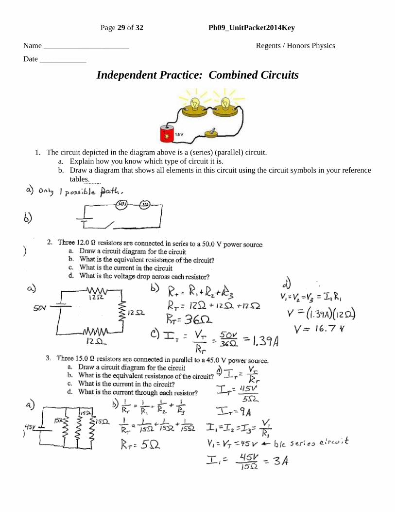
Independent Practice: Combined Circuits
1. The circuit depicted in the diagram above is a (series) (parallel) circuit.
a. Explain how you know which type of circuit it is.
b. Draw a diagram that shows all elements in this circuit using the circuit symbols in your reference
tables.

Page 30 of 32 Ph09_UnitPacket2014Key

Page 31 of 32 Ph09_UnitPacket2014Key
6. A 12 Ω and an 18 Ω resistor are connected to a 48-V power source.
a. What is the equivalent resistance of the circuit if the resistors are connected in series?
b. What is the equivalent resistance if the resistors are connected in parallel?
c. Draw the circuit diagram. Include in your diagram the minimum number of ammeter(s) that will
measure the current through EACH of the resistors and the minimum number of voltmeters that
will measure the voltage across EACH of the resistors.
7. A circuit is constructed as shown in the figure below. The voltmeter reads 63.0 V
a. Calculate the current through the 36 Ω resistor.
b. What is the voltage drop across the 42Ω resistor? . . . 54Ω resistor?
c. Which resistor dissipates the most energy per second?
d. What is the voltage of the power source (Hint: use Kirchoff’s loop law)?

Page 32 of 32 Ph09_UnitPacket2014Key
8. Referring to the circuit in the above diagram.
a. Determine what the equivalent resistance is.
b. Determine the current flowing through each resistor.
c. Determine the voltage drop across each resistor.