paddle-wheel flow controller for on/off control · 2014-11-27 · ≤ 80 ma (no load) ≤ 50 ma ......
TRANSCRIPT
8032
p. 1/6www.burkert.com
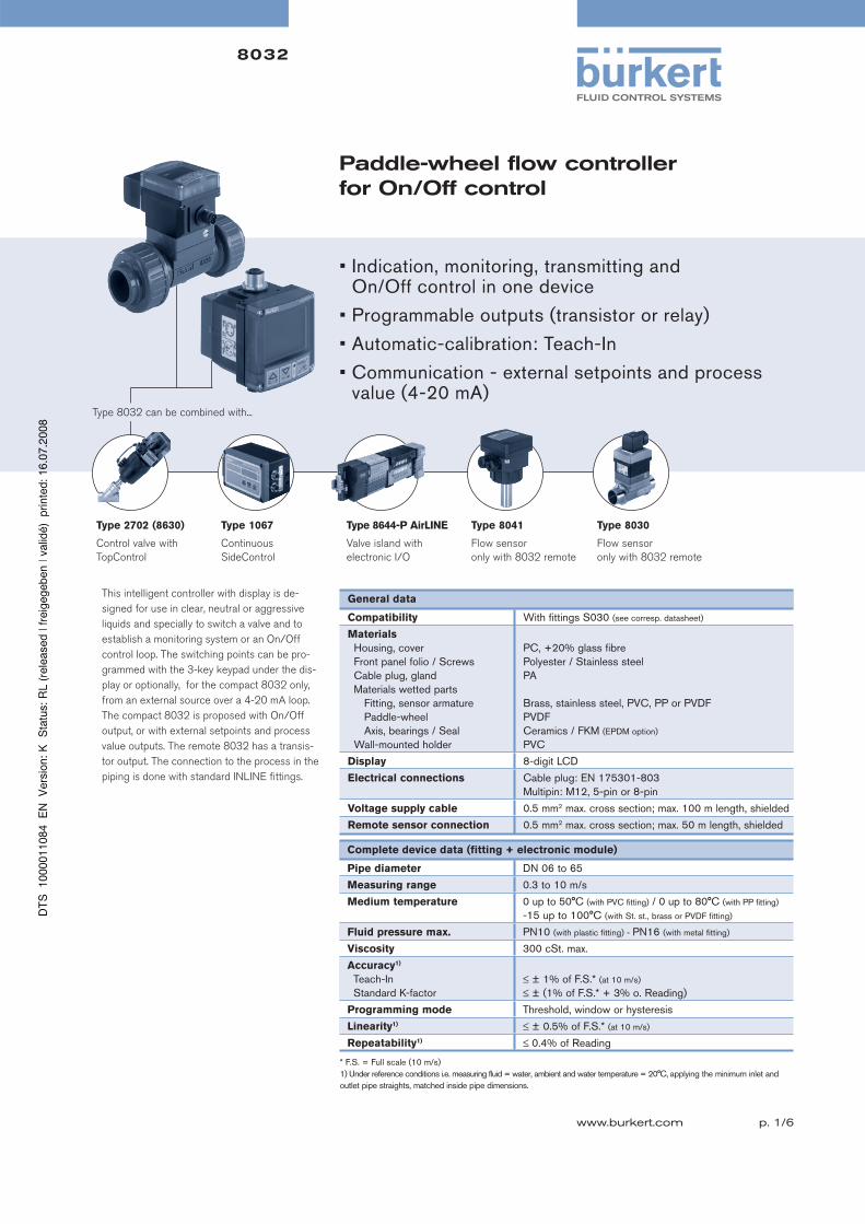
Paddle-wheel flow controller for On/Off control
This intelligent controller with display is de-
signed for use in clear, neutral or aggressive
liquids and specially to switch a valve and to
establish a monitoring system or an On/Off
control loop. The switching points can be pro-
grammed with the 3-key keypad under the dis-
play or optionally, for the compact 8032 only,
from an external source over a 4-20 mA loop.
The compact 8032 is proposed with On/Off
output, or with external setpoints and process
value outputs. The remote 8032 has a transis-
tor output. The connection to the process in the
piping is done with standard INLINE fittings.
General data
Compatibility With fittings S030 (see corresp. datasheet)
Materials
Housing, cover Front panel folio / Screws Cable plug, gland Materials wetted parts Fitting, sensor armature Paddle-wheel Axis, bearings / Seal Wall-mounted holder
PC, +20% glass fibre Polyester / Stainless steelPA
Brass, stainless steel, PVC, PP or PVDFPVDFCeramics / FKM (EPDM option)
PVC
Display 8-digit LCD
Electrical connections Cable plug: EN 175301-803Multipin: M12, 5-pin or 8-pin
Voltage supply cable 0.5 mm2 max. cross section; max. 100 m length, shielded
Remote sensor connection 0.5 mm2 max. cross section; max. 50 m length, shielded
Type 2702 (8630)
Control valve with
TopControl
Type 1067
Continuous
SideControl
Type 8032 can be combined with...
• Indication, monitoring, transmitting and On/Off control in one device
• Programmable outputs (transistor or relay)
• Automatic-calibration: Teach-In
• Communication - external setpoints and process value (4-20 mA)
Complete device data (fitting + electronic module)
Pipe diameter DN 06 to 65
Measuring range 0.3 to 10 m/s
Medium temperature 0 up to 50°C (with PVC fitting) / 0 up to 80°C (with PP fitting)
-15 up to 100°C (with St. st., brass or PVDF fitting)
Fluid pressure max. PN10 (with plastic fitting) - PN16 (with metal fitting)
Viscosity 300 cSt. max.
Accuracy1)
Teach-In Standard K-factor
≤ ± 1% of F.S.* (at 10 m/s)
≤ ± (1% of F.S.* + 3% o. Reading)
Programming mode Threshold, window or hysteresis
Linearity1) ≤ ± 0.5% of F.S.* (at 10 m/s)
Repeatability1) ≤ 0.4% of Reading
* F.S. = Full scale (10 m/s)1) Under reference conditions i.e. measuring fluid = water, ambient and water temperature = 20°C, applying the minimum inlet and outlet pipe straights, matched inside pipe dimensions.
Type 8644-P AirLINE
Valve island with
electronic I/O
Type 8041
Flow sensor
only with 8032 remote
Type 8030
Flow sensor
only with 8032 remote

p. 2/6
8032
The compact flow controller 8032 is built up
with an electronic module SE32 associated to
a fitting S030 with integrated measurement
paddle-wheel. The output signal is provided via
cable plug according to EN 175301-803 and/or
a M12 multipin connector.
The wall-mounted flow controller 8032 is built
up with an electronic module SE32 associated
to a wall-mounted holder. The output signal is
provided via two M12 multipin connector.
When liquid flows through the pipe, the 4
magnets, inserted in the paddle-wheel set in
rotation, produce a measuring signal in the
transducer. The frequency is proportional to
the flow velocity of the fluid. A conversion
coefficient (K factor, available in the instruction manual of the fitting), specific to each
pipe (size and material) enables the conversion of this frequency into flow rate.
Design and principle of operation
1 92 3 4 5 6 7 8 10
4
8
20
-4
-8
-12
-16
-20
16
121% o.F.S. + 3% o. R.1% o.F.S.
o. F.S. = of Full Scaleo. R. = of Reading
with standard K factorwith Teach-In
Bürkert typical curve
Flow velocity [m/s]
Max. error [%]
Accuracy diagram
Operation and display
The device can be calibrated by means of the K-factor, or via the Teach-In function.
Customized adjustments, such as engineering units, output, filter, bargraph are carried out on site.
The operation is specified according to three levels:
Indication in operating mode / Display
- measured flow
- high threshold value
- low threshold value
Parameter definition
- engineering units (International measuring units)
- K-factor / Teach-In function
- selection of switching mode (window, hysteresis)
(see main features)
- selection of threshold value (see main features)
- delay
- filter
- 10-segment bargraph (select min. and max. value)
Test
- switching threshold test with flow simulation
(dry-run test operation)
Electronic SE32
FittingS030
Electronic SE32
Wall-mountedholder
To scroll-up the menu or
increase a value
To scroll-down the menu
or select a digit to be
modified
Confirm input and
menu points
Status of the switching output
(red LED)
Bargraph
Large digital display
with 8 characters
(4 digital characters and
4 alphanumeric characters)
Electrical data
Power supply
Compact version Wall-mounted version
filtered and regulated 12-30 V DCDepends on the remote sensor:8041: 18-30 V DC8020, 8030: 12-30 V DCother: min. 12 V DC, max. 30 V DC
Current consumption
Compact version Wall-mounted version
≤ 80 mA (no load)
≤ 50 mA (no load) + remote sensor current consumption
Input
External setpoint
Frequency (remote version)
4-20 mA, galvanic insulation max. input impedance: 250 ΩPulse signal: 2 to 400 Hzinput impedance: 10 kΩ
Outputs
Transistor (programmable)
Relay (programmable)
(compact version)
Process value (option)
(compact version)
NPN and PNP, open collector, 5-30 V DC, max. 700 mA, 0 to 300 Hzprotect against short circuit.3A/250 V AC or 3A/30 V DC.3A/48 V AC or 3A/30 V DC2).4-20 mA, galvanic insulationLoop resistance: 1000 Ω at 30 V DC, 800 Ω at 24 V DC, 500 Ω at 18 V DC
Reversed polarity of DC Protected
Environment
Ambient temperature 0 up to + 60°C (operating and storage)
Relative humidity ≤ 80%, non condensated
Standards and approvals
Protection class IP65
Standard
EMC Security Vibration Shock
EN 610006-2, 610006-3EN 61010-1 EN 60068-2-6EN 60068-2-27
2) Valid for: external setpoint input, process value output

p. 3/6
8032
Contact
OLO OHI
Hysteresis, invertedContact
OLO OHI
Hysteresis, not invertedContact
OLO OHI
Window, invertedContact
OLO OHI
Window, not inverted
Hysteresis mode Window mode
Main features
8032 with external setpoint option.
The switching points are automatically adjusted by the 4-20 mA input signal originating from a PLC.
- Power supplied by the PLC
- On/Off relay output
8032 with standard On/Off output
- 2 switching modes for the output, either hysteresis or window, inverted or not
- Programmable delay before switching
- Possible outputs depending on the version: relay, transistor NPN, transistor PNP, frequency
8032 with process value option.
This version delivers an electric signal whose value is the image of the measured quantity.
- On/Off relay output
- 4-20 mA output
- external setpoint (4-20 mA input)
Installation
The 8032 flow controller can easily be installed into any Bürkert INLINE fitting system Type S030 by means of a Quarter-Turn.
Minimum straight upstream and downstream distances must be observed. According to the pipe’s design, necessary distances can be bigger
or use a flow conditioner to obtain the best accuracy. For more information, please refer to EN ISO 5167-1.
EN ISO 5167-1 prescribes the straight inlet and outlet distances that must be complied with when installing fittings in pipe lines in order to
achieve calm flow conditions. The most important layouts that could lead to turbulence in the flow are shown below, together with the associated
prescribed minimum inlet and outlet distances. These ensure calm, problem-free measurement conditions at the measurement point.
18 x DN 5 x DN
15 x DN 5 x DN
Extension
Reduction
DN = orifice Fluid direction -->
50 x DN 5 x DN
40 x DN 5 x DN
Regulating
valve
2 x 90°
elbow joint
3 dimensional
2 x 90°
elbow joint
90°
elbow joint
or T-piece
25 x DN 5 x DN
20 x DN 5 x DN
The flow controller can be installed into either horizontal or vertical pipes.
Pressure and temperature ratings must be respected according to the selected fitting material.
The suitable pipe size is selected using the diagram Flow / Velocity / DN.
The controller is not designed for gas flow control.
Correct Incorrect
Correct
Incorrect
IncorrectCorrect
Correct
Incorrect
p. 4/6
8032
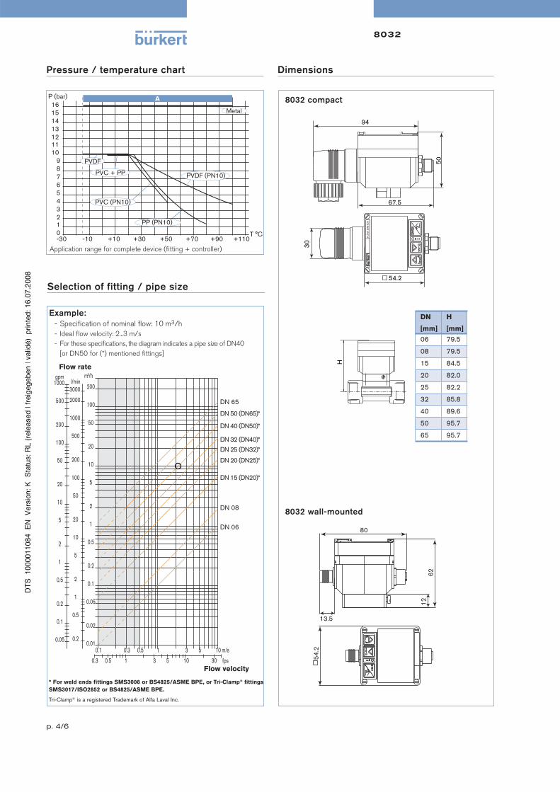
Selection of fitting / pipe size
Pressure / temperature chart
Application range for complete device (fitting + controller)
Dimensions
DN
[mm]
H
[mm]
06 79.5
08 79.5
15 84.5
20 82.0
25 82.2
32 85.8
40 89.6
50 95.7
65 95.7
H
6212
13.5
54.2
80
8032 wall-mounted
FLO
W S
WIT
CH
94
50
67.5
54.2
30
8032 compact
109876543210-30 -10 +10 +30 +50 +70 +90 +110
PVDF (PN10)
PVC (PN10)
PP (PN10)
PVC + PP
Metal
PVDF
161514131211
AP (bar)
T °C
Example:
- Specification of nominal flow: 10 m3/h
- Ideal flow velocity: 2...3 m/s
- For these specifications, the diagram indicates a pipe size of DN40
[or DN50 for (*) mentioned fittings]
Flow rate
Flow velocity
0.1 0.3 0.5 1 3 5 100.01
0.02
0.05
0.1
0.2
0.5
1
2
5
10
20
50
100
200
m3/h
0.2
0.5
1
2
5
10
20
50
100
200
500
1000
2000
3000l/min
0.3 0.5 1 3 5 10 30
m/s
fps
gpm
0.05
0.1
0.2
0.5
1
2
5
10
20
50
100
200
500
1000
DN 65
DN 50 (DN65)*
DN 40 (DN50)*
DN 32 (DN40)*
DN 25 (DN32)*
DN 20 (DN25)*
DN 15 (DN20)*
DN 08
DN 06
* For weld ends fittings SMS3008 or BS4825/ASME BPE, or Tri-Clamp® fittings
SMS3017/ISO2852 or BS4825/ASME BPE.
Tri-Clamp® is a registered Trademark of Alfa Laval Inc.

p. 5/6
8032
Ordering chart for Controller Type 8032
Vo
lta
ge
su
pp
ly
Inp
ut
Ou
tpu
t
Ele
ctr
ical
co
nn
ecti
on
Ite
m n
o.
12-30 V DC --- NPN Cable plug EN 175301-803* 436 474
PNP Cable plug EN 175301-803* 434 871
NPN and PNP 5-pin M12 plug 436 473
Relay 5-pin M12 plug and cable plug EN 175301-803* 436 475
4-20 mA1) 4-20 mA2) +Relay 8-pin M12 plug and cable plug EN 175301-803* 444 699
A compact flow controller Type 8032 consists of:
- a compact electronic module SE32
- an INLINE fitting S030 (DN 06 - DN 65) (Refer to corresponding datasheet - has to be ordered separately)
1) External setpoint 2) Process value * Europe / Asia (G / Rc): M16 x 1.5 mm cable plug USA / CDN (NPT): NPT 1/2 cable plug
Ordering chart for accessories (to be ordered separately)
De
scri
pti
on
Ite
m n
o.
4-pin M12 female cable connector with plastic threaded locking ring, for remote version 448 856
4-pin M12 female connector moulded on cable (2 m, shielded), for remote version 448 857
5-pin M12 female cable connector with plastic threaded locking ring 917 116
5-pin M12 female connector moulded on cable (2 m, shielded) 438 680
8-pin M12 female cable connector with plastic threaded locking ring 444 799
8-pin M12 female connector moulded on cable (2 m, shielded) 444 800
Cable plug EN 175301-803 with cable gland (Type 2508) 438 811
Cable plug EN 175301-803 with NPT1/2 “ reduction without cable gland (Type 2509) 162 673
Vo
lta
ge
su
pp
ly
Inp
ut
Ou
tpu
t
Ele
ctr
ical
co
nn
ecti
on
Ite
m n
o.
12-30 V DC frequency NPN and PNP 5-pin M12 male and 4-pin M12 female 448 861
A wall-mounted flow controller Type 8032 consists of:
- a wall-mounted electronic module SE32
- a flow sensor Type 8020, 8030, 8030-HT, 8041 or 8070 - frequency output with pulse
signal (Refer to corresponding datasheet - has to be ordered separately)

p. 6/6
8032
To find your nearest Bürkert facility, click on the orange box → www.burkert .com
In case of special application conditions,please consult for advice.
We reserve the right to make technical changes without notice. 0702/7_EU-en_00891781
Interconnection possibilities with other Bürkert products
PLC
Type 8032 -
Compact
flow controller
Type 6212 -
Solenoid valve
Type 5281 -
Solenoid valve
Type 2712 (1067)
Globe valve with
control head
Input 4-20 mA
(Ext. setpoint)
Relay
output
Transistor
output
4-20 mA
output
Compact flow controller
Wall-mounted flow controller
Type 8032 -
Wall-mounted
flow controller
Type 6212 -
Solenoid valve
Type 8030 -
For pipes DN 06 to 65
Type 8070
Low flow measurement
Transistor
output
Frequency
input
Type 8020 -
For pipes DN 06 to 400
Type 8041 -
Flow measurement of
contamined fluids
for pipes DN 06 to 400