pact core facilities update - ukccs research centre€¢ flue gas candle filter ( >99% ash...
TRANSCRIPT

UKCCSRC PACT
CORE FACILITIES
SHEFFIELD
July 2017
The UKCCSRC is supported by the Engineering and Physical Sciences Research Council as part of the Research Councils UK Energy Programme
Jon GibbinsDirector, UK CCS Research CentreProfessor of Power Plant Engineering and Carbon CaptureUniversity of Sheffieldwww.ukccsrc.ac.ukwww.pact.ac.ukj.gibbins@sheffield.ac.uk
Mohamed PourkashanianDirector UKCCSRC PACT Director University of Sheffield Energy 2050
About UKCCSRC PACT
• UKCCSRC Pilot-scale Advanced Capture Technology facilities – Funded by: BEIS (formerly DECC) and EPSRC– Cranfield, Edinburgh, Imperial, Leeds, Nottingham, Sheffield– Member of International CCS Test Centre Network (for UK)
• Scope: Specialist national facilities for research in advanced fossil-fuel energy, bioenergy and carbon capture technologies– Comprehensive range of pilot-scale facilities – Supporting specialist research and analytical facilities – Leading academic expertise
• Aim: Support and catalyse industrial and academic R&D to accelerate the development and commercialisation of novel low carbon technologies
• Objectives– Bridge gap between bench-scale R&D and industrial pilot trials– Provide shared access to industry and academia

For technologies to mature to be a “bankable asset class” this gap must also be bridged. Nuclear, Wind, Solar, Marine are all TRL9 and are still benefitting from fundamental research.
Faraday discussion, 2016, http://pubs.rsc.org/en/content/articlelanding/2016/fd/c6fd00046k#!divAbstract, based on http://arena.gov.au/files/2014/02/Commercial-Readiness-Index.pdf
Fundamental research needed to increase Commercial Readiness as well as TRL
Bankable Asset Class
Market competitiondriving widespread development
Multiple Commercial Applications
Commercial Scale Up
Commercial Trial Small Scale
Hypothetical Commercial Proposition
System test, launch and operation
System/subsystem development
Technology demonstration
Technology development
Research to prove feasibility
Basic technology research
TRL
CRI
9
8
7
6
5
4
3
2
1
6
5
4
3
2
1
PACT Core Facilities
Coal/Biomass, NG-CCGT , Biofuel, CO2
Capture Plant
Large –Scale Combustion Test Facilities

PACT Core Facility: Overview
Gas heaters
250kW Combustion Rig
Oxyfuel gas mixing skid
Trace gases
Steam boiler and injection skid
EGR
Large gas storage tanks: N2, CO2 and O2
Gas TurbinesFuels
Site stack
Central exhaust duct
EGR
Amine Plant
Air compressor
Synthetic Flue Gas Mixing facility (O2, CO2, N2, trace gases)
air supply skid
CAPABILITIES: 1. Post-combustion carbon capture (synthetic flue gas)
3. Oxyfuel carbon capture (coal/biomass)
4. Post-combustion carbon capture (Gas Turbines)
2. Post-combustion carbon capture (coal/biomass)

Solvent- based Carbon Capture Plant(Amine) Solvent-based Carbon Capture Plant

Solvent- based Carbon Capture Plant
Overview 8m/300mm Absorber and Desorber columns
2x 3m packed sections Random/structured packing
Integrated FGD (carbonate) wash system for removal of SOx from coal flue gas
Flue gas treated: 210 Nm3/h; eqiv. to 150kW coal flue gas
Removes 1 tonne of CO2 per day (MEA) with over 98% purity
Solvent sampling on absorber and desorber Material corrosion testing sites
Trace gas injection capability
Analytical capability Gas composition Temperature monitoring Pressure monitoring (e.g. foaming)
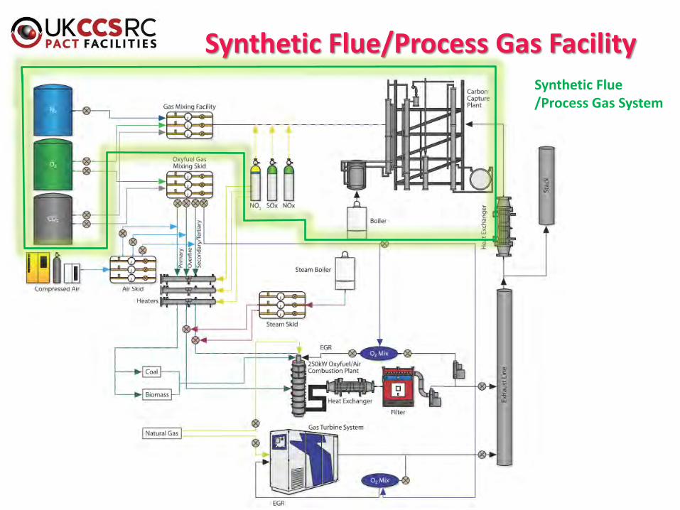
Synthetic Flue/Process Gas FacilitySynthetic Flue /Process Gas System

Synthetic Flue/Process Gas Facility
Overview• Three gas metering and mixing lines,
fed from O2, CO2 and N2 storage tanks
• Complemented by trace gas injection NOx and SOx, other trace gasses
• Generate simulated flue/process gases
• Connected directly to the Solvent-based Carbon Capture Plant

250kW Air Combustion Plant
Overview• ~250kWth, 4.5m high; 0.9m radius, cylindrical, down-fired
rig with 8 sections • Fuel: Coal, Biomass, Co-firing, Gas (primarily preheating)
• 2 x (interchangeable) coal/biomass burners - scaled from Doosan Power Systems commercial low-NOx burners
• Dedicated, high precession air metering skid • Flue gas candle filter ( >99% ash removal);
• Furnace pressure (negative) balanced by exhaust fan• Temperature and flow monitored water cooling system
for the combustion rig, flue gas duct and heat exchanger.• SCADA operating system with internet monitoring

PACT Core Facility: Layout
250KW Air Combustion Plant +(Amine) Solvent Based Carbon Capture Plant =

PACT Core Facility: Layout
250KW Air Combustion Plant +(Amine) Solvent Based Carbon Capture Plant = Post Combustion Capture from Coal, Biomass, Co-firing, Gas Systems:

Oxyfuel capture from Coal, Biomass, Co-firing, Gas systems: (primarily) Real oxyfuel mode+(primarily) Synthetic oxyfuel mode
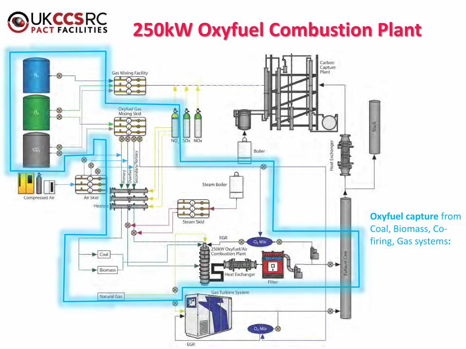
250kW Oxyfuel Combustion Plant
Oxyfuel capture from Coal, Biomass, Co-firing, Gas systems:
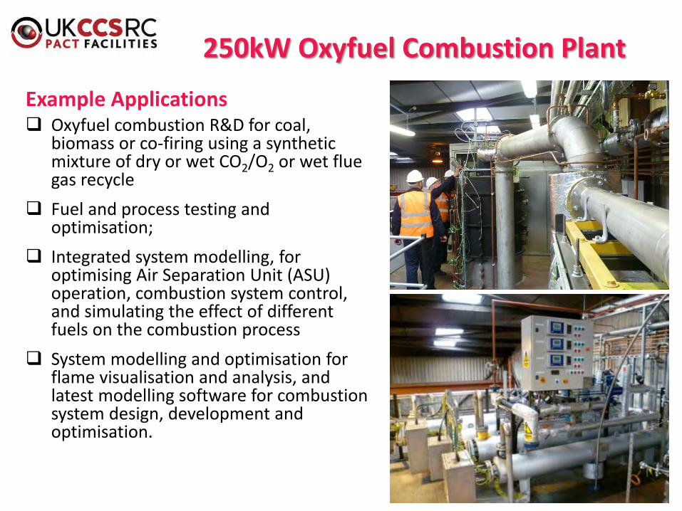
250kW Oxyfuel Combustion Plant
Example Applications Oxyfuel combustion R&D for coal,
biomass or co-firing using a synthetic mixture of dry or wet CO2/O2 or wet flue gas recycle
Fuel and process testing and optimisation;
Integrated system modelling, for optimising Air Separation Unit (ASU) operation, combustion system control, and simulating the effect of different fuels on the combustion process
System modelling and optimisation for flame visualisation and analysis, and latest modelling software for combustion system design, development and optimisation.

Pilot-Scale Integrated Experimental Facilities for BIO-Cap Project
Gas Mixing
Facilities
250kW Air/Oxy Rig
ICP-OES & DMS
500 Carbon Capture
Plant

Imaging system has been developed by the University of Kent (Dr Gang Lu & Prof Yong Yan)
Flame Imaging System

18
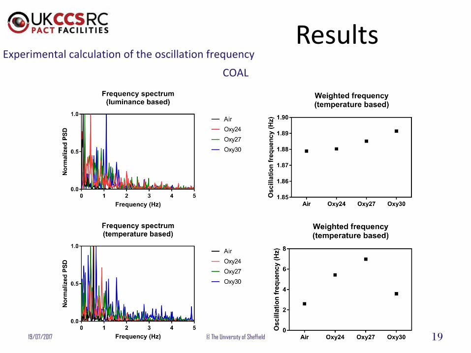
ResultsExperimental calculation of the oscillation frequency - COAL
19/07/2017 © The University of Sheffield
Air Oxy24
Oxy30Oxy27
Original videos
19/07/2017 © The University of Sheffield 19
ResultsExperimental calculation of the oscillation frequency
COAL

Gas Turbine System
Overview
Two Turbec T100 Microturbines
Consume 330kW of Natural gas
Fuel: Natural gas, biogas, syngas, diesel, kerosene, methanol, LPC
Generation 100kWe and 150kWth
Overall efficiency up to 77% (33% electrical)

Gas Turbine System
Turbine – the hot, pressurised
gas expands through the
turbine to drive the turbine and
the compressor and generator,
which are all on the same shaft
Flue gas heat exchanger – uses
the hot flue gas to heat water
System description
compressor – radial centrifugal compressor compresses ambient air before sending to recuperator
recuperator – preheats the compressed combustion air with the heat from the flue gases
combustor – a lean combustion environment ensures low NOx, CO and hydrocarbon emissions

Gas Turbine System
Analytical Facilities Flow rates, temperatures, dew
points and pressure measurements throughout the system.
Electrical and thermal power measurement
Combustion Gas Analysis Horiba VA-3000 Analyser I: Model VA-
3002 for CO and NOx analysis
Horiba VA-3000 Analyser II: Model VA-3113 for CO2, O2 and SO2 analysis
Signal 3000HM Heated FID for total hydrocarbon analysis
Particulate Spectrometer (Cambustion DMS500 Fast Particulate Spectrometer) Classification by particle electrical
mobility
Online analysis of particle mass, number and size spectra
range (5 ‒ 1000nm)

Gas Turbine System
GT +(amine) Solvent Based Carbon Capture Plant =
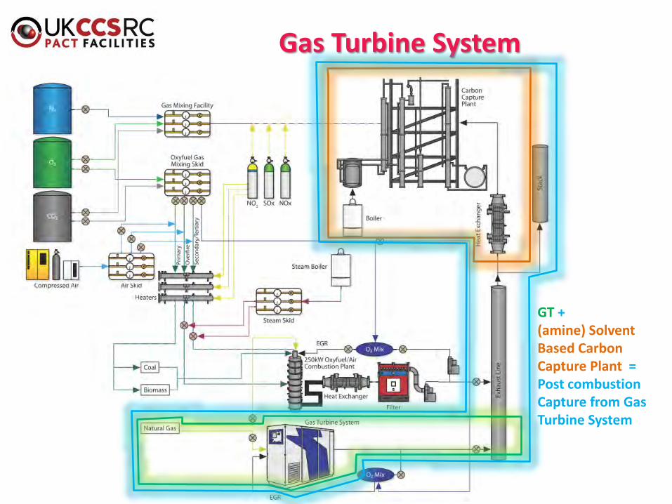
Gas Turbine System
GT +(amine) Solvent Based Carbon Capture Plant = Post combustion Capture from Gas Turbine System

250 kW plant Gas Turbine

Analytical Facilities: LabsAnalytical labs
Unique CEM mobile laboratory for solid-state detector based ICP-OES (SUWIC)
Cambustion DMS500 Fast particulateanalyser
CHNS/O Elemental Analyser
GC MS and TG-MS
Thermogravimetric Analyser and TG-MS
FT-IR and TG-IR
Portable SERVOFLEX MiniMP gas analysers (CO2 and O2)

Analytical Facilities: online monitoring
Gas analysis systems for both 250kW plant and the gas turbine.
Particle size analyser
Continuous Emissions Monitoring Laboratory (CEML) mobile laboratory, (Inductively Coupled Plasma) for monitoring metallic emissions from thermal processes;
Real-time, online diagnostics
Simultaneous multi-metal analysis

Summary
Comprehensive research capability and support Consolidating a wide range of facilities and supporting expertise Maximising equipment utilisation through shared access to industry
and academia Services
R&D Services Collaborative research Contract research
Analytical services Technical consultancy Training
Dr Kris MilkowskiPACT Business Development Manager UKCCSRC PACT Core Facilities Unit 2 Crown Works Industrial EstateRotherham RoadBeightonSheffield S20 1AH, UK
e-mail: [email protected]: +44 (0) 7802720369