pacs: numerical approach and evaluation of a concept for dimensioning ... - dlr … numerical...
TRANSCRIPT

ORIGINAL PAPER
PACS: numerical approach and evaluation of a conceptfor dimensioning pressure-actuated cellular structures
B. Gramuller1• C. Huhne1
Received: 18 January 2015 / Revised: 7 August 2015 / Accepted: 10 August 2015
� Deutsches Zentrum fur Luft- und Raumfahrt e.V. 2015
Abstract A biologically inspired concept is investigated
which can be utilized to develop energy efficient, and
lightweight adaptive structures for various applications.
Summarizing basic demands and barriers regarding shape-
changing structures, the basic challenges of designing
morphing structures are listed. The analytical background
describing the physical mechanisms of PACS is presented
in detail. This work focuses on the numerical approach of
calculating the geometrically, highly nonlinear deformation
states of pressure-actuated cellular structures. Beyond the
calculation of equilibrium states, a form-finding algorithm
is presented, which allows determining structural designs
following predefined target shapes. Initially made
assumptions are dropped incrementally to show the effects
on the accuracy of the modeling. Finite element method-
based calculations and experimental test results provide the
computational target data for the varying grade of simpli-
fications. Representative of more complex structures, like
aircraft control surfaces, the examined geometries are
chosen to evaluate the generic numerical methods and to
validate the functionality of the basic working principle.
Keywords PACS � Shape-variable � Morphing �Form-finding � Cellular � Pressure
1 Introduction
Fluidic actuators can be used to integrally combine an
efficient, lightweight and accurate drive system with a
deformable structure. The advantages of pneumatic and
hydraulic actuators as compared to other drive systems are
examined by Huber et al. [1]. The specific stresses and
strains as well as the resolution of motion of these actuators
lead to a wide range of use and predestinates it for aero-
nautical applications. In nature, the combination of fluidic
actuation and a shape-variable structure can be discovered
at the family of nastic plants. Representatives like the
thigmonastic Cape Sundew (Drosera Capensis) and the
Venus Flytrap (Dionaea Muscipula), which use their
touch-sensing capabilities to trap small insects are exam-
ples for a successful implementation of biological integral
morphing structures. Another common example is given by
the seismonastic Mimosa Pudica that protects its fragile
leafage through a folding mechanism when stimulated.
Sibaoka investigated the mechanisms of nastic plants. He
describes the loss and gain of turgor—internal hydrostatic
cell sap pressure—(symbolized by H2O in at the upper
right depiction of Fig. 1) as the driving force for the dis-
tortions [2]. Pressures of more than 8 MPa can be reached
[3].
Researchers working on form variable cellular structures
made huge efforts to adapt this principle to a mechanically
usable structural system. Vos et al. developed the pressure
adaptive honeycomb (PAH) concept for actuating their
Gurney Flap. This trailing edge flap autonomously changes
its shape in different flight altitudes and takes advantage of
aerostatic pressure differences [4]. By using thin-walled
honeycombs, made from FAA-certifiable aluminum, a very
lightweight structure results. Pagitz et al. transferred the
idea of fluidic pressure driven morphing structures into a
This paper is based on a presentation at the German Aerospace
Congress, September 16–18, 2014, Augsburg, Germany.
& B. Gramuller
1 DLR, Institute of Composite Structures and Adaptive
Systems, Lilienthalplatz 7, Brunswick, Germany
123
CEAS Aeronaut J
DOI 10.1007/s13272-015-0164-1

two-dimensional concept with a promising degree of
deformation, high flexibility and sizeable characteristic [5].
Compared to the PAH concept, the main difference of
PACS consists in the variable side length of its cells.
Moreover, a thickened central web structure between cells
of varying differential pressures is necessary for bearing
pressure-induced bending moments. The utilization of
foam cores in a sandwich construction could compensate
the additional weight at the cell sides compared to the
PAH. A PACS structure of multiple pressure dependent
shapes can be mathematically deduced by manipulating the
equilibrium state of each cell and thereby of the cell
compound. Pagitz et al. showed with numerical methods
how the deformational shape of such a structure can be
controlled for multiple cells and cell rows using flexure
hinges [6]. They established a form-finding approach
which allows conceiving structures that vary their shapes
stepless between multiple form functions.
The functional flexibility of PACS is demonstrated by
the examples of a morphing airfoil and a shape adaptive
backrest [7]. With their real-life implementation of a single
row PACS demonstrator Gramuller et al. showed the
practicability of the theoretical basis [8]. Figure 1
summarizes the preceding work on shape-changing struc-
tures using pressurized cellular structures.
2 Demands on adaptive structures and difficulties
The design of conventional structures is usually driven by
two groups of requirements. The first one is of program-
matic manner and holds general demands like low costs,
high quality and reduced development time. As a second
group, structural requirements with reference to structural
mechanics are determined by the expected loads and in
addition by geometrical boundary conditions. These needs
are also valid for shape-variable structures and a PACS
structure has to withstand the design loads and simultane-
ously ensure to keep deformations in a tolerable range.
The actuation of shape-changing structures can be
divided in two functional elements, the energy adjusting
element (e.g. compressor), which transforms energy (e.g.
electrical energy) from the auxiliary energy source into a
usable energy form (e.g. pressure and volume) and the
energy converter that modifies the received energy in order
to obtain the desired energy driven effects (e.g. deforma-
tion) [9]. The special attribute about PACS is the integra-
tion of energy converter and structure as shown in Sect. 3.
Together with the increased complexity, the overall
power demands and the additional weight of the energy
converter, adjusting element and peripheral sub-compo-
nents like wiring, the first basic problem about shape-
variable active structures appears. It can be condensed as
follows: The development and implementation of a concept
for shape-changing structures is only reasonable if the
anticipated benefit outweighs the invested efforts. Figure 2
specifies this general demand. The energy consumption and
related peripheral weight, depends on the required forces
and travel ranges needed to deform the structure. Common
Fig. 1 Example from nature: Venus Flytrap (Dionaea Muscipula;
left); Concepts of deduced operating principle: (1) PAH [14] and (2)
PACS [5] Fig. 2 Challenge of generating profitable adaptive structures
B. Gramuller, C. Huhne
123

concepts for aeronautical shape-variable structures like the
horn concept [10], the ripless plain flap [11], the active
flexspar actuator [12] and the vertebrate structure [13] are
in need of stiff and weighty structural components to
withstand aerodynamic forces. On the contrary, Barrett
et al. [14] even describe the possibility of reducing struc-
tural weight by adaptive structures. An artificial muscle
structure based on the pressure driven honeycomb, simi-
larly to PACS benefits of its weight efficient structural
integrated actuator and provides the non-concentrated for-
warding of distributed aerodynamic loads. Structural hard
points can thus be eliminated for further weight reduction
and provide an additional contribution to the advantages
for airborne applications.
A raise of structural stiffness increases the sufferable
external forces on the corresponding structure but height-
ens the necessary efforts for changing the structures shape
and limits the boundaries of tolerable deformation. Thus
the second challenge of developing a profitable morphing
concept can be formulated: an efficient concept for shape-
variable structures circumvents the seeming contradiction
of a specific design being stiff and flexible at the same time
(see Fig. 3). There are some concepts available which have
implemented this principle, like the flexible rib from
Monner [15], the cellular planar morphing structure from
Vasista et al. [16], the tendon-actuated compliant cellular
trusses [17] or the zigzag wingbox [18]. The common
principle behind these examples is a steered release of
specific degrees of freedom (dofs) by integrating hinges,
compliant mechanisms or linear bearings.
Other demands on the morphing structure’s actuation
element concern its performance-based properties, the
maximum forces respectively momentums, e.g. stall torque
for an electric motor, and the related travel ranges.
Regarding the combination of actuator and structure, the
structural response, depending on the actuators character-
istics as well as on the structural stiffness and mass
distribution, underlies the requirements for control speed
and frequency and is essential for the definition of the
operating range of such a concept. Other, non-unique air-
borne subjects as fatigue strength and certification are
essential for building a real-life morphing structure. Before
investigating efforts in these topics, the potentials of a
concept for adaptive structures are revealed in this further
step of doing research into PACS.
PACS are conceptualized to generate two-dimensional
deformations on single-curved surfaces. The conceivable
operating range regarding structural dimensions can be
varied from centimeters to meters without having any
losses of functionality, due to the possibility of adapting
certain counteracting design variables. Their potential for
future airborne or general structures is based on its light-
weight design and energetically efficient actuation. These
properties constitute a good foundation for profitable
adaptive structure. The concept is further characterized by
a blended structure-actuator construction, possesses a
necessary minimum of stiffness in the hinge regions of the
cells and generates structural stiffness through pressuriza-
tion. With a high flexibility in shape variations and an
adaptive structural stiffness PACS meets the second chal-
lenge of morphing concepts.
3 Physics of PACS
The analytical equations necessary to find and control the
equilibrium state of a pressure-actuated cellular structure
are essential for understanding the mechanics of this con-
cept. Both proofing the already found numerically com-
puted results for validity through recalculation and
investigating the conceptual boundaries of a realization
using compliant hinges, can be reached with the imple-
mentation of a respective algorithm. After a summary of
the already published information, a continuative approach
for the developed implementations is presented. The dif-
ferent strategy beyond that carries new aspects about
handling internal and external forces as well as an alter-
native form-finding approach.
3.1 Background
The functional principle of pressure-actuated cellular
structures is based on the reduction of inner energy due to
volume maximization. Figure 4(1) provides a comprehen-
sible visualization of the effects, which lead to the driving
forces of this concept. Similar to a flattened balloon, a
flexible membrane does not have any defined state of shape
without being pressurized. Not until the balloon is loaded
with a particular pressure p1 the resulting distribution of
forces lead onto bending moments and, assumingFig. 3 Challenge of circumventing the dilemma of structural flexi-
bility, stiffness and strength
PACS: numerical approach and evaluation…
123
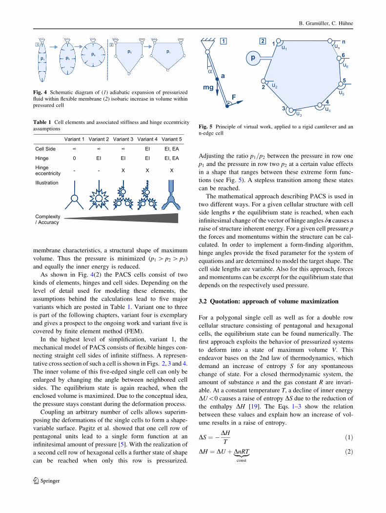
membrane characteristics, a structural shape of maximum
volume. Thus the pressure is minimized (p1 [ p2 [ p3)
and equally the inner energy is reduced.
As shown in Fig. 4(2) the PACS cells consist of two
kinds of elements, hinges and cell sides. Depending on the
level of detail used for modeling these elements, the
assumptions behind the calculations lead to five major
variants which are posted in Table 1. Variant one to three
is part of the following chapters, variant four is exemplary
and gives a prospect to the ongoing work and variant five is
covered by finite element method (FEM).
In the highest level of simplification, variant 1, the
mechanical model of PACS consists of flexible hinges con-
necting straight cell sides of infinite stiffness. A represen-
tative cross section of such a cell is shown in Figs. 2, 3 and 4.
The inner volume of this five-edged single cell can only be
enlarged by changing the angle between neighbored cell
sides. The equilibrium state is again reached, when the
enclosed volume is maximized. Due to the conceptual idea,
the pressure stays constant during the deformation process.
Coupling an arbitrary number of cells allows superim-
posing the deformations of the single cells to form a shape-
variable surface. Pagitz et al. showed that one cell row of
pentagonal units lead to a single form function at an
infinitesimal amount of pressure [5]. With the realization of
a second cell row of hexagonal cells a further state of shape
can be reached when only this row is pressurized.
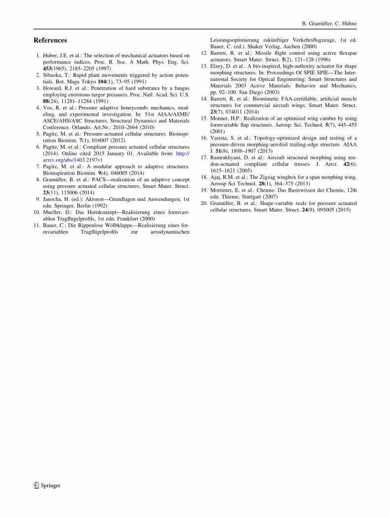
Adjusting the ratio p1=p2 between the pressure in row one
p1 and the pressure in row two p2 at a certain value effects
in a shape that ranges between these extreme form func-
tions (see Fig. 5). A stepless transition among these states
can be reached.
The mathematical approach describing PACS is used in
two different ways. For a given cellular structure with cell
side lengths v the equilibrium state is reached, when each
infinitesimal change of the vector of hinge angles da causes a
raise of structure inherent energy. For a given cell pressure p
the forces and momentums within the structure can be cal-
culated. In order to implement a form-finding algorithm,
hinge angles provide the fixed parameter for the system of
equations and are determined to model the target shape. The
cell side lengths are variable. Also for this approach, forces
and momentums can be excerpt for the equilibrium state that
depends on the respectively used pressure.
3.2 Quotation: approach of volume maximization
For a polygonal single cell as well as for a double row
cellular structure consisting of pentagonal and hexagonal
cells, the equilibrium state can be found numerically. The
first approach exploits the behavior of pressurized systems
to deform into a state of maximum volume V. This
endeavor bases on the 2nd law of thermodynamics, which
demand an increase of entropy S for any spontaneous
change of state. For a closed thermodynamic system, the
amount of substance n and the gas constant R are invari-
able. At a constant temperature T, a decline of inner energy
DU\0 causes a raise of entropy DS due to the reduction of
the enthalpy DH [19]. The Eqs. 1–3 show the relation
between these values and explain how an increase of vol-
ume results in a raise of entropy.
DS ¼ �DHT
ð1Þ
DH ¼ DU þ DnRT|fflffl{zfflffl}
const
ð2Þ
Fig. 4 Schematic diagram of (1) adiabatic expansion of pressurized
fluid within flexible membrane (2) isobaric increase in volume within
pressured cell
Table 1 Cell elements and associated stiffness and hinge eccentricity
assumptions
Variant 1 Variant 2 Variant 3 Variant 4 Variant 5
Cell Side ∞ ∞ ∞ EI EI, EA
Hinge 0 EI EI EI EI, EA
Hinge eccentricity - - X X X
Illustration
Complexity / Accuracy
Fig. 5 Principle of virtual work, applied to a rigid cantilever and an
n-edge cell
B. Gramuller, C. Huhne
123

DU ¼ �Z 2
1
ðp Vð Þ � puÞ|fflfflfflfflfflfflfflffl{zfflfflfflfflfflfflfflffl}
const
oV ¼ ðp� puÞðV1 � V2Þ ð3Þ
Pagitz et al. make use of this physical law and formulate
the following equations for calculating the equilibrium
state of a cellular structure. In order to present the complete
numerical knowledge about PACS and since this approach
is used to verify modeling variant 1, a short summary about
the approach of volume maximization is given in Eqs. (4)–
(11) [5].
f ¼XnP
n¼1
fPn þXnP�1
n¼1
fHn ¼ 0 ð4Þ
with fPn ¼ pPoAPn
ouPnð5Þ
and fHn ¼ pHoAHn
ouHnð6Þ
The global force vector f for all pentagonal cells of
quantity nP and hexagonal cells of quantity nH vanishes in
equilibrium. It is calculated as the sum of weighted
derivatives of the cells’ areas APn or APn with respect to the
rotational degree of freedom u.
Du ¼ �K uð Þ�1f ðuÞ ð7Þ
K ¼XnP
n¼1
KPn þXnP�1
n¼1
KHn ð8Þ
with KPn ¼ pPo2APn
ou2Pn
ð9Þ
and KHn ¼ pHo2AHn
ou2Hn
ð10Þ
For the calculation of the increment Du of the cell side
angles at the current state, the stiffness matrix K is needed
and can be found as the weighted second derivative of the
respective areas. It was shown that for given cell side
lengths v the equilibrium state, defined by the cell side
angles a can thus be calculated iteratively.
A separate way to reach equilibrium is to retain parts of the
matrix of cell side angles and thus compute the required cell
side lengths. These angles can be defined such that the struc-
ture’s surface moves into a given target shape. The strategy of
calculating the shape of a given structure when pressurized is
thereby replaced with a form-finding algorithm [5]:
Dv ¼ kSTt1;t2rS ð11Þ
Computing the increment Dv for the current cell side
lengths v and the associated cell side angles in equilibrium
state allows to iteratively approaching the target shape. The
factor k defines the step length during form finding in order
to minimize the 2-norm of the residual shape vector rS that
comprises the difference between current and target angles.
STst1;st2 is the sensitivity matrix coupling the change of
angles with the change of cell side lengths for the two
target states st1 and st2.
3.3 Variant 1: infinitesimal hinge stiffness
An alternative solution to the approach of volume maxi-
mization is given by the method of virtual work. As it relies
on the information of hinge and cell side positions, angles
and displacements, it is easy to extract element stresses and
also to apply external loads. Through the more universal
nature of this method, it can be modified comparatively
quickly. The flexibility has however to be paid in the form
of computation time. The general approach, the calculation
of structural loads, the procedure of considering external
forces as well as a fast converging form-finding algorithm
are first illuminated on the basis of modeling variant 1. For
reduced assumptions this implementation is extended in the
subsequent chapters.
3.3.1 General approach
A mechanical system is in equilibrium when the derivative
of the potential energy P vanishes:
_P ¼ � dWdr
¼ �f ¼equil:0 ð12Þ
The difference between the following approach and the
one presented by Pagitz et al. is rooted in the calculation of
potential energy. The derivative of this potential energy is
equal to the introduced global force vector f . Implicitly using
the potential energy of pressurized volumes dislocates the
computational approach from the mechanical units. The
theory of virtual work utilizes the forces which explicitly act
on single structural elements, like in this case cell sides. It can
be used for conservative forces which are present here. The
application of virtual displacements dr provides an efficient
way of calculating the derivative of potential energy. A
simple example shall explain the approach.
Figure 5(1) shows a flexible mounted rigid cantilever
which is loaded with a beam perpendicular force F and the
vertical weight mg. The virtual work DW is then calculated
as the sum of all external forces FðeÞi times the associated
force parallel component of the virtual displacement Dri.Equation 13 gives the solution for the depicted example
and allows calculating the angle a for the equilibrium state
(see Eq. (15)).
dW ¼Xn
i¼1
FðeÞi dri ð13Þ
PACS: numerical approach and evaluation…
123

dW ¼ F � 1
2mgsinðaÞ
� �
ada ð14Þ
dWda
¼equil:0; for aeq ¼ asin
2F
mg
� �
ð15Þ
For a pressurized single cell of j ¼ ½m� cell sides the
equilibrium shape can be found equally. The cell’s geom-
etry in the two-dimensional space is determined by a
matrix of cell side lengths v with size [m] and a matrix of
rotational dofs u with size k ¼ ½m� 3�. To find the equi-
librium state for a given PACS the cell side lengths provide
the known and the rotational dofs or cell side angles the
unknown variables. Figure 5(2) shows the notation of the
variables for a single cell with pressure load p.
The cell side vector is
aj ¼ aj;x aj;y½ �; with aj�
�
�
� ¼ vj: ð16Þ
Assuming infinite stiffness for cell sides and flexible
hinges the force vector is computed with the unit vector e3
to
Fj ¼ pvjaj
aj�
�
�
�
� e3
" #
¼ p aj � e3
: ð17Þ
The local virtual displacement vector dx is computed as
a function of the virtual displacement at the rotational dof
duk and is illustrated in Fig. 6. It is determined as the
displacement at the center of each cell side due to the
virtual displacement duk:
dxj;k ¼ g v; u; dukð Þ ð18Þ
The function gðÞ holds the trigonometric terms, which
are necessary to describe a polygon with the parameters v
and u that can be found in the work of Pagitz et al. [5].
With the additional information about the virtual dis-
placement duk at hinge k the displacement of the point of
origin for the resultant force vector Fj, dxj;k is calculated.
The vector quantity of the force parallel virtual dis-
placement is formed by the vertical projection of the local
displacement on the local force:
drj;k ¼dxj;k � Fj
Fj
�
�
�
�2
ð19Þ
The first derivative of the potential energy can be
computed to
_Pk ¼ � dWk
duk¼ �
Pmj¼1 Fjdrj;kduk
¼ �fk ¼ 0: ð20Þ
In order to solve this equation and find the equilibrium
shape of the cellular structure the Newton’s method with
quadratic convergence for this system provides a valuable
approach. This iterative solution is chosen because of its
flexibility with respect to an arbitrary cells and cell sides:
xnþ1 ¼ xn �f ðxnÞ_f ðxnÞ
Newton’s methodð Þ ð21Þ
The current state variable utþ1 for the iteration step t þ 1
results from the following equation:
utþ1 ¼ ut �_P
o _P=ou¼ ut �_PK�1 ð22Þ
The second derivative of the potential energy is needed
to calculate the stiffness matrix K (cf. Eq. 23). The size of
K is ½m� 3 � m� 3�.
K ¼ o _P
ou¼
o _P1
ou1
o _P1
ou2
o _P2
ou1
o _P2
ou2
� � �
o _P1
oum�3
o _P2
oum�3
..
. . .. ..
.
o _Pm�3
ou1
o _Pm�3
ou2
� � � o _Pm�3
oum�3
2
6
6
6
6
6
6
6
6
6
4
3
7
7
7
7
7
7
7
7
7
5
ð23Þ
The equilibrium state for an m-edged single cell is thus
found. Applied to a cellular structure of i ¼ n cells these
equations keep their validity and can be superimposed to
describe more complex structures. Depending on the kind
of cell combination the number of independent state vari-
ables alternates and thus the size of the stiffness matrix
does. For a double row PACS structure of i1 ¼ nP pen-
tagonal and i2 ¼ nH hexagonal cells, which Pagitz et al.
described in their publication, the number of independent
variables reduces to nP mP � 3ð Þ½ � þ nH mH � 3 � 2ð Þþ½1� ¼ 2nP þ nH þ 1 what is equal to 3nP. Figure 7 shall
illuminate this assertion.
Similarly to the computation of the equilibrium for the
single cell, the derivative of the potential energy is built byFig. 6 Schematic description of the kinematical correlations of an
m-edged single cell used for the approach of virtual work
B. Gramuller, C. Huhne
123

_Pi;k ¼ � dWi;k
dui;k¼ �
Pmj¼1 Fi;jdri;j;kdui;k
: ð24Þ
The stiffness matrix K for this example has the size
½3nP � 3nP� and can again be deduced from the derivative
of the potential work after the state variable vector u:
K ¼ o _P
ou¼
o _P1;1
ou1
o _P1;1
ou1;2
o _P1;2
ou1
o _P1;2
ou2
� � �
o _P1;1
oun;mn�3
o _P1;2
oun;mn�3
..
. . .. ..
.
o _Pn;mn�3
ou1
o _Pn;mn�3
ou2
� � � o _Pn;mn�3
oun;mn�3
2
6
6
6
6
6
6
6
6
6
6
4
3
7
7
7
7
7
7
7
7
7
7
5
ð25Þ
3.3.2 Calculation of stresses
For the structural design of PACS as well as for the
appraisal of use-dependent practicability, stress values
provide the necessary input. The computation of stresses is
also processed using the method of virtual work. Equal to
the virtual rotation du a virtual displacement dv of cell side
lengths causes the virtual work dW . The quotient of virtual
work and virtual displacement yields to the force value
within the observed cell side:
_Pj ¼ � dWj
dvj¼ �
Pmj¼1 Fjdrjdvj
¼ �fj ¼ 0 ð26Þ
Depending on the respective wall thickness tj, the cell
side stress for a PACS cell of depth dj is
rj ¼fj
tj: ð27Þ
For all of the subsequent depictions showing structural
stresses a wall thickness of tj ¼ 1 mm and a depth of dj ¼1 mm is underlying.
3.3.3 External forces
Equally to the pressure-induced forces external loads of
number ne, if present, are considered by calculating the
product of external force Fext times the related virtual
displacement drext:
_Pk ¼ � dWj
dukþ dWext
duk
� �
¼ �Pm
j¼1 Fjdrj;k þPne
h¼1 Fext;hdrext;h;k
duk¼ 0 ð28Þ
3.3.4 Form finding
The difference between finding the equilibrium state of a
given PACS structure and calculating the structure for a
desired shape variation lies in the set of known and
unknown variables. As visualized in Fig. 8 the outer shape
of PACS can be defined by one angle per pentagonal cell
plus one additional angle for the connector cell side of the
last pentagonal cell. For a double row cantilever with two
attainable shape functions at the pressure sets st1 and st2,
2ðnp þ 1Þ known variables are given. The vector of known
variables is u0. The mixed vector of unknown state vari-
ables w whereas consists of np � 1 pentagon and nh þ 1
hexagon angles summarized in u1 and 4np þ 1 pentagonal
and 3nh þ 1 hexagonal cell side lengths v.
u ¼ u0
u1
� �
; w ¼ u1
v
� �
ð29Þ
The first derivative of the virtual work is again found
according to Eq. (24) as the equilibrium state still has to
fulfill Eq. (20). Thus the unknown variables add up to 9npthis number is three times higher than the number of
equations from (20), 3np. The solution for a PACS which
deforms into the given states of shape at a given pressure
set is thus not unique. An algorithm that mathematically
combines unknown variables can be used to consider
manufacturing requirements or external geometrical
boundary conditions.
Pagitz et al. presented a method for the form finding of
PACS structures that is based on computing a sensitivity
matrix which relates the change of rotational dofs to the
change of cell side lengths [5]. The initial state of u0 is
Fig. 7 Reduction of the number of independent state variables due to
geometrical couplingFig. 8 Known variables at pressure set pst1 for the form-finding
approach
PACS: numerical approach and evaluation…
123

chosen to be identical with the manufacturing state. 2000 to
20,000 iterations are necessary to find the shape of an
optimized structure with an accuracy of at least 0.01�related to the target values [6].
A novel approach for solving the form-finding problem
for a PACS structure reduces the necessary number of
iterations significantly. In contrast to evaluating the devi-
ation between current and target cell angles after each
iteration step, the residual energy potential of the structure
is used to compute the increment for the change of cell side
lengths. This allows to additionally coupling the change of
unknown rotational dofs u1 to the change of cell side
lengths v. For an initial state the target shapes st1 and st2are used. The stop criterion from the approach of calcu-
lating a PACS structure’s equilibrium state is still valid and
leads to a maximum angular deviation towards target
geometry of 1.90e-7� for the example shown in Fig. 10.
The target shapes are characterized by an angular deflec-
tion of ±5� per pentagonal cell. The related pressure sets
can be obtained from the respective depiction.
Figure 9 shows the convergence behavior in dependency
of the hinge stiffness, which is introduced in the following
section. The number of iterations needed to fulfill the stop
criterion for the remaining virtual work is equal for cal-
culating the equilibrium state and for form finding
assuming infinitesimal hinge stiffness. As the change of the
manufacturing state of the structure and thus the change of
initial cell side angles are also coupled to the change of cell
side lengths, a non-zero hinge stiffness does not substan-
tially raise the necessary number of iterations.
Similar to Eq. (22) the mixed vector of unknown state
variables w is computed by
wtþ1 ¼ wt �_P
o _P=ow¼ wt �_PS�1: ð30Þ
where S is the sensitivity matrix which relates the change
of unknown variables to the virtual work and thereby to the
remaining energy potential. It is calculated at the equilib-
rium state of u1, where
_P ¼ � dWdu1
¼ 0; ð31Þ
by
S¼ o2P
ouow¼ o _P
ow
¼
o _P1;st1
ou1;1
o _P2;st1
ou1;1
� � �
o _P1;st1
ou1;2np�1
o _P1;st1
ov1
o _P2;st1
ou1;2np�1
o _P2;st1
ov1
� � �
o _P1;st1
ov7np�1
o _P2;st1
ov7np�1
..
. . .. ..
. . .. ..
.
o _P3np;st1
ou1;1� � � o _P3np;st1
ou1;2np�1
o _P3np;st1
ov1
� � �o _P3np;st1
ov7np�1
o _P1;st2
ou1;1
o _P2;st2
ou1;1
� � �
o _P1;st2
ou1;2np�1
o _P1;ts2
ov1
o _P2;st2
ou1;2np�1
o _P2;st2
ov1
� � �
o _P1;st2
ov7np�1
o _P2;st2
ov7np�1
..
. . .. ..
. . .. ..
.
o _P3np;st2
ou1;1� � � o _P3np;st2
ou1;2np�1
o _P3np;t2
ov1
� � �o _P3np;st2
ov7np�1
2
6
6
6
6
6
6
6
6
6
6
6
6
6
6
6
6
6
6
6
6
6
6
6
6
6
6
6
6
6
6
4
3
7
7
7
7
7
7
7
7
7
7
7
7
7
7
7
7
7
7
7
7
7
7
7
7
7
7
7
7
7
7
5
:
ð32Þ
The inverse of the sensitivity matrix is computed
according to the Moore–Penrose method. For the present
case of a non-quadratic matrix, this approach minimizes
the 2-norm of _PS�1 and leads to stable convergence
behavior.
Compared to Fig. 8 the structure depicted in Fig. 10
shows three additional elements which came up to be
Fig. 9 Convergence curve for exemplary structure extracted from the
form-finding procedure for infinitesimal and finite hinge stiffness
Fig. 10 Resulting structure from the form-finding procedure after
nine iterations for E = 2.0 GPa
B. Gramuller, C. Huhne
123

important during the work on the realization of a PACS
structure [8]. Finite hinge stiffness and eccentric hinge
positions are described in the further chapters. The con-
nection concept at both ends of the cantilever is needed for
clamping a real-life structure to its test bench or to connect
multiple PACS units with each other. It is developed
together with Pagitz et al. [7].
3.4 Variant 2: finite hinge stiffness
In contrary to the previously shown approach the cells of
nastic plants do not dispose of discrete hinges of
infinitesimal stiffness. Though a man-made structure can
be built which most widely satisfies this assumption by
using pinned hinge joints, compliant mechanisms hold two
essential advantages. According to the functionality of a
plant cell a compliant PACS cell is pressure-sealed in
radial direction without any auxiliary structure. Beyond
that, the integral design of a compliant PACS saves weight
and substitutes the respective assembly process. Both, for
the calculation of the pressure dependent shape of a given
PACS structure and for the form-finding process, the
integration of a finite hinge stiffness in the numerical
model enhances the results. As this section extends the
already presented approach, the equations of Sect. 3.3 are
still valid and necessary.
The equivalent stiffness for a compliant hinge joint can
be calculated by considering the hinge to be a beam with
the flexural stiffness EI. This beam of length sl and
thickness tl (see Fig. 11) holds the torsional stiffness cl at
the non-coupled (independent state variables and depen-
dent dofs, cf. Fig. 7) hinge l. The size of c is ½9np þ 1�. For
a material of Young’s modulus E it results in
cl ¼EIz;l
sl¼ E
t3l12sl
: ð33Þ
As depicted in Fig. 11 conjugated eccentric hinges l; 1
and l; 2 are combined to locally concentrated one-dimen-
sional hinge by:
ci ¼1
1=cl;1 þ 1=cl;2: ð34Þ
The formula for calculating the virtual work dWk has to
be extended by the approach of torsional stiffness and
completed by the resulting distortion dependent momen-
tums. The updated virtual work is
dWk ¼Xm
j¼1
Fjdrj;k þXq
l¼1
cl Dut;ldul;k þ1
2du2
l;k
� �
; ð35Þ
with Dut;l ¼ ut;l � u0: ð36Þ
The angular deflection Dut;l at the iteration step t is
equal to the difference of the non-coupled angle ut;l and the
manufactured hinge angle u0 of the unloaded structure.
As cl depends on the structural design and is constant
and the varieties of ul are already part of the existing cal-
culations, the computation time is not much affected by
this supplement. The approach of virtual work further
allows adding this sub-formula without huge changes in the
overall code.
3.5 Variant 3: eccentric hinges
Without a novel approach for describing mechanical ele-
ment properties variant 3 provides a remedy for the
assumption of locally concentrated one-dimensional hinge
elements. In a real-life PACS structure the hinge length
varies between five and twenty percent of the cell size. As
the center of a compliant hinge not always coincides with
the intersection point of linked cell sides, the dislocation of
the effective hinge positions can be on the same scale.
Figure 12 gives an example for unavoidable eccentricity of
hinge joints. Two possibilities for the design of compliant
hinges in the crossover point of three interconnected cell
sides are shown for a glass fiber-reinforced plastic (GFRP)
cell with a cell width of 50 mm. It can be obtained that at
Fig. 11 Compliant hinge element with wall thickness t and length s
and resulting bending stiffness c
Fig. 12 Eccentric compliant hinges at crossing points of adjacent
cells
PACS: numerical approach and evaluation…
123

this crossover an accumulation of material increases
bending stiffness. The effective hinge location migrates to
an eccentric position.
Overriding the approximation of concentrated hinges
claims the implementation of eccentric hinge elements and
leads to a more detailed and realistic model.
In order to keep the number of additional unknown
variables small and considering computation efforts, the
eccentric hinge is modeled as rigid triangle with fixed side
lengths and only one rotational dof uf. In the context of the
approach of virtual work, a suitable way to describe this
triangle is depicted in Fig. 13. The vector of eccentricity
fi;l at cell i and hinge l defines the geometry of the element.
Together with the angle uf0 the initial state for the eccen-
tric hinge is defined.
The vector u which contains the state variables for
pentagonal and hexagonal cells has to be extended by
rotation angle uf. The number of independent variables
thus increases by 4np � 4 to 7np � 4. The equations for
calculating the vector of virtual work, stiffness and sensi-
tivity matrices are still valid. The adaption of u however
leads to a new size of these arrays. The form-finding
approach described in Sect. 3.3.4 is also applicable for
eccentric compliant hinges. Figure 10 depicts an exem-
plary double row PACS structure, which is calculated on
the basis of variant 3.
3.6 Variant 5: FEM-based approach
The benefit of the reduction of assumptions is evaluated by
the comparison of the previous approaches with a more
detailed modeling method. Thereby the available variants
can be assessed with regard to the computation complexity.
The FEM tool Ansys is used to calculate the deformations
of a generic PACS structure. As this model is built of three-
dimensional linear solid elements including axial and
bending stiffness, the FEM-based approach provides the
most reliable data. The outcomes are thus used as a ref-
erence for the comparison of the alternative computational
methods.
The target structure is a double row cantilever, which is
designed to suit a modular concept. It consists of six pen-
tagonal and five plus two hexagonal cells. The length of the
cantilever is 350 mm. Two separate regions are defined for
meshing the structure. The cell sides elements are deter-
mined to have an element size of 2 mm, hinge regions are
modeled with a refined element size of 0.3 mm—see
Fig. 14.
4 Evaluation
4.1 Verification of variant 1
The deformation and stress results for a loaded cantilever
calculated according to variant 1 (cf. Table 1) are com-
pared with the publicized results from Pagitz et al. [5].
Despite the completely different numerical formulations
the results show good correspondence. Figure 15 pictures
the deformed cantilever including cell side stresses for
method of volume maximization (VM)—left and virtual
work (VW)—right. Deviations of colors are due to varying
imaging procedures what is made clear in following
quantitative exposition.
Fig. 13 Definition and notation of eccentric hinge element
Fig. 14 Visualization of the FEM model for the modular double row
cantilever
Fig. 15 Visual comparison of deformational and stress results
between the approach of volume maximization—left and virtual
work—right
B. Gramuller, C. Huhne
123

For this approach of virtual work a virtual rotation of
du ¼ 2e-6 is used. _P�
�
�
�\1e-5 is chosen as stop criterion
for the iteration.
Tables 2 and 3 show the quantitative values for hinge
positions and cell side normal stresses for the rightmost
pentagonal cell of the depicted cantilever. The different
pressurization conditions are identified by st1 and st2. The
numbering of hinge points and cell sides can be obtained
from Fig. 15. The maximum relative deviation of 2.18e-5
for hinge coordinates and 1.12e-5 for stresses results. The
validity of the approach of virtual work is thus verified.
4.2 Comparison of differing modeling variants
Differences in accuracy of the three presented implemen-
tations utilizing the method of virtual work are illuminated
in this exemplary comparison. The outcomes summarize
the presented work on the numerical computation of PACS
and assess the quality of the obtained results according to
the concomitant efforts. The pressure set-up is chosen to
cover both, a state of shape near the geometrical conver-
gence which requires high pressures (I) and the case where
the geometry is not converged and sensitive to slight
pressure changes (II).
The FEM data described in Sect. 3.6 is used as reference
for calculating deviations. Table 4 comprises the quanti-
tative values for the rotational deformation at the first cell
side of the sixth pentagonal cell as well as the percentage
variance in relation to FEM data. An improvement of
accuracy from ?37.14 to 9.47 % for the first pressure
setting and from ?85.88 to ?0.59 % for the second one
clearly confirms the benefit of increased modeling
complexity. Especially in low pressure regions, which are
characterized by a non-converged geometrical deforma-
tion, the modeling methods including infinite hinge stiff-
ness provide superior results. This can be explained by the
stiffening of the overall structure and a decreasing sensi-
tivity against non-pressure-induced forces with rising cell
pressures. The eccentricity of the hinge points directly
affects the energetic potential of the pressured cellular
structure. The significant impact on the accuracy of com-
putational results is quantified. Figure 16 visualizes the
outcomes.
4.3 Validation by experimental investigations
The deformation results delivered by the most accurate
numerical non-FEM method, the eccentric hinge approach
are compared with the outcomes of the investigation of the
only existing real-life PACS structure. To simplify manu-
facturing all of the cells are designed to have the same
dimensions. A GFRP single row cantilever consisting of
six cells of width 50 mm and length 450 mm results that
Table 2 Hinge coordinates at
equilibrium state for volume
maximization (VM) and virtual
work (VW)
HingePos 28 29 30 31 32
xst1,VM (mm) 634.7420 648.7360 706.0260 628.0109 677.3280
xst1,VW (mm) 634.7526 648.7465 706.0382 628.0246 677.3419
yst1,VM (mm) 497.7787 496.9998 553.0957 597.5519 605.7876
yst1,VW (mm) 497.7714 496.9911 553.0862 597.5448 605.7789
xst2,VM (mm) 884.3763 884.3378 937.0112 984.3722 989.0510
xst2,VW (mm) 884.3754 884.3366 937.0098 984.3712 989.0498
yst2,VM (mm) -157.5712 -207.5713 -236.3032 -156.6585 -206.4391
yst2,VW (mm) -157.5725 -207.5725 -236.3046 -156.6603 -206.4406
Table 3 Cell side stresses at
equilibrium state for volume
maximization (VM) and virtual
work (VW)
CellSide 37 38 39 40 41
rst1,VM (MPa) -29.4297 33.7915 192.5062 193.2165 17.8448
rst1,VW (MPa) -29.4297 33.7915 192.5066 193.2167 17.8446
rst2,VM (MPa) 42.7883 204.0862 133.5500 131.7476 98.2794
rst2,VW (MPa) 42.7882 204.0865 133.5502 131.7478 98.2794
Table 4 Rotational deformation at cell side one of the sixth pen-
tagonal cell for the three presented modeling variants and deviations
from FEM results
Variant 1 Variant 2 Variant 3 Variant 5
Db6;1;pI (�) 35.04 29.80 27.97 25.55
gVx;FEM;pI (%) ?37.14 ?16.63 ?9.47 –
Db6;1;pII (�) 6.32 2.86 3.42 3.40
gVx;FEM;pII (%) ?85.88 -15.88 ?0.59 –
PACS: numerical approach and evaluation…
123

reaches an entire span of 300 mm. The main reasons for
this demonstrator are to prove the theoretical methods
about this concept for its practicability and to evaluate the
calculation results. The authors are aware of the fact that
the utilization of GFRP materials may cause problems
regarding moisture intrusion due to thermal cycling. This
process is intensified by the gas-tight cellular design of the
PACS. As this generic investigation is not bound by the use
of any specific material, also fatigue effects are not con-
sidered so far. The design process and manufacturing
strategy of this prototype is part of a previous publication
[8]. It shall be mentioned that the concept for pressurizing
the PACS is not trivial. The solution depicted in Fig. 18
shows the tube cartridge device. It solves the related
stiffness problem by utilizing an elastic silicone tube but
strongly limits the applicable pressures. Further investiga-
tions on the end cap design lead to a more elegant and in
particular energy efficient solution. The deformation sup-
portive end cap (DSEC) is introduced by Gramuller et al.
[20]. In favor of further examinations the physical imple-
mentation of a double row demonstrator utilizing the
DSEC is presented therein.
For the given PACS geometry built from the GFRP
material HexPly913 with a Young’s modulus of E ¼42:0 GPa an averaged hinge eccentricity of fi;l;x ¼ 4 mm,
the resulting hinge stiffness of ci;l ¼ 10:938. . .27:344 N
rad
and the pressure p ¼ 0:2 MPa, numerical calculations are
processed. Table 5 contains the deformation results for the
first cell side of the sixth cell. A deviation of 1.013 %
shows a good match between numerical—according to
variant 3 and experimental data and confirms the previous
insights. The experimental value is measured with an
analogue protractor.
The deformation results as well as normalized cell side
stresses for the cell side thickness of 1 mm are depicted in
Fig. 17. The related photographs of the prototype demon-
strator can be compared in Fig. 18.
5 Discussion of results
The method of virtual work provides an alternative solution
to the approach of volume maximization. Solving the
geometrical highly nonlinear problem of a pressurized
PACS structure can be used for both the computation of
equilibrium shape and for form finding. Three different
approaches with an increasing level of model accuracy are
presented and their results are compared with FEM-based
outcomes and experimentally achieved values. Two sub-
stantial aspects about these results shall be discussed.
As it can be obtained from Fig. 12 in a kinematical
structure where compliant mechanisms are used to realize
hinge joints, the determination of the position of effective
pivot points is not trivial. Depending on the hinge’s
geometry and loading, this location shifts relatively to the
Fig. 16 Visualization of deformations from the four types of
numerical computation for two different pressure set-ups
Table 5 Comparison of deformation results for the single row can-
tilever at cell side one of cell six at p = 0.2 MPa
Db6;1;eccð�Þ Db6;1;expð�Þ gecc;expð%Þ
124.62 123 ?1.01
Fig. 17 Results from simulation according to the eccentric hinge
approach for the single row cantilever prototype at p0 = 0, p1 = 0.05
and p2 = 0.15 MPa
B. Gramuller, C. Huhne
123

adjacent cell sides. Concerning the more detailed compu-
tational methods with increased accuracy, the extraction of
the hinge stiffness and eccentricity of a given structure is
not trivial. Within a real PACS structure the gradual
transition between hinge and cell side elements compli-
cates the definition of the hinge stiffness according to
Eq. (33) and the related eccentricity f. Simulating the load
dependent deformation behavior of each compliant hinge
joint may provide relief and give additional insight in this
relationship.
With the implementation of variant 3, the consideration
of eccentric hinges, some assumptions could be dropt but
others are still implemented. Beyond the theme of con-
centrated hinges, the axial and bending stiffness of cell
sides as well as the axial stiffness of hinge elements is not
considered. Further numerical approaches may profit from
the implementation of these open issues. Though the pre-
sented methods yet show good accordance with FEM-
based computations and experimental investigations.
6 Conclusion
The most important demand on each shape-variable
structure is defined by the imperative need for improve-
ment. Therefore, the demands on the concept of pressure-
actuated cellular structures are investigated. The existing
numerical theory about PACS is summarized and con-
firmed by a novel approach using the method of virtual
work. Two advanced variants were presented extensively
which increase the level of detail within the numerical
model by first dropping the assumptions of infinitesimal
hinge stiffness and subsequently of centric hinges. In
comparison to a FEM calculation the different modeling
variants achieved varying degrees of accordance for the
two calculated states of internal pressure. With a deviation
of 9.47 and 0.59 % in angular deflection for different
pressures, the numerical approach using eccentric hinges
provides the most accurate results. Thereby it is approved
that the increased modeling and computational effort
enhances the quality of the results.
A single row PACS prototype consisting of six equally
shaped pentagonal cells is used to demonstrate the func-
tionality of the concept and to validate the computed data.
The compliance regarding the accuracy of deformational
results between eccentric hinge model and experimentally
measured values lies at about 1 % for this investigation.
The discussion of results shows that additional investi-
gations on the compliant hinge elements, which allow
deriving accurate descriptive parameters would improve
the numerical model. An increase in the level of detail by
dropping further modeling assumptions would also have a
positive effect. This can be reached by the consideration of
axial stiffness for hinge and cell side elements as well as by
the consideration of the bending stiffness of cell sides.
Fig. 18 Demonstrator ‘‘Single Row Cantilever’’ at p0 = 0, p1 = 0.05
and p2 = 0.15 MPa [8]
PACS: numerical approach and evaluation…
123
References
1. Huber, J.E. et al.: The selection of mechanical actuators based on
performance indices. Proc. R. Soc. A Math. Phys. Eng. Sci.
453(1965), 2185–2205 (1997)
2. Sibaoka, T.: Rapid plant movements triggered by action poten-
tials. Bot. Maga Tokyo 104(1), 73–95 (1991)
3. Howard, R.J. et al.: Penetration of hard substrates by a fungus
employing enormous turgor pressures. Proc. Natl. Acad. Sci. U.S.
88(24), 11281–11284 (1991)
4. Vos, R. et al.: Pressure adaptive honeycomb: mechanics, mod-
eling, and experimental investigation. In: 51st AIAA/ASME/
ASCE/AHS/ASC Structures, Structural Dynamics and Materials
Conference. Orlando. Art.Nr.: 2010–2664 (2010)
5. Pagitz, M. et al.: Pressure-actuated cellular structures. Bioinspi-
ration Biomim. 7(1), 016007 (2012)
6. Pagitz, M. et al.: Compliant pressure actuated cellular structures
(2014). Online cited 2015 January 01. Available from: http://
arxiv.org/abs/1403.2197v1
7. Pagitz, M. et al.: A modular approach to adaptive structures.
Bioinspiration Biomim. 9(4), 046005 (2014)
8. Gramuller, B. et al.: PACS—realization of an adaptive concept
using pressure actuated cellular structures. Smart Mater. Struct.
23(11), 115006 (2014)
9. Janocha, H. (ed.): Aktoren—Grundlagen und Anwendungen, 1st
edn. Springer, Berlin (1992)
10. Mueller, D.: Das Hornkonzept—Realisierung eines formvari-
ablen Tragflugelprofils, 1st edn. Frankfurt (2000)
11. Bauer, C.: Die Rippenlose Wolbklappe—Realisierung eines for-
mvariablen Tragflugelprofils zur aerodynamischen
Leistungsoptimierung zukunftiger Verkehrsflugzeuge, 1st ed.
Bauer, C. (ed.). Shaker Verlag, Aachen (2000)
12. Barrett, R. et al.: Missile flight control using active flexspar
actuators. Smart Mater. Struct. 5(2), 121–128 (1996)
13. Elzey, D. et al.: A bio-inspired, high-authority actuator for shape
morphing structures. In: Proceedings Of SPIE SPIE—The Inter-
national Society for Optical Engineering: Smart Structures and
Materials 2003 Active Materials: Behavior and Mechanics,
pp. 92–100. San Diego (2003)
14. Barrett, R. et al.: Biomimetic FAA-certifiable, artificial muscle
structures for commercial aircraft wings. Smart Mater. Struct.
23(7), 074011 (2014)
15. Monner, H.P.: Realization of an optimized wing camber by using
formvariable flap structures. Aerosp. Sci. Technol. 5(7), 445–455
(2001)
16. Vasista, S. et al.: Topology-optimized design and testing of a
pressure-driven morphing-aerofoil trailing-edge structure. AIAA
J. 51(8), 1898–1907 (2013)
17. Ramrakhyani, D. et al.: Aircraft structural morphing using ten-
don-actuated compliant cellular trusses. J. Aircr. 42(6),
1615–1621 (2005)
18. Ajaj, R.M. et al.: The Zigzag wingbox for a span morphing wing.
Aerosp Sci Technol. 28(1), 364–375 (2013)
19. Mortimer, E. et al.: Chemie: Das Basiswissen der Chemie, 12th
edn. Thieme, Stuttgart (2007)
20. Gramuller, B. et al.: Shape-variable seals for pressure actuated
cellular structures. Smart Mater. Struct. 24(9), 095005 (2015)
B. Gramuller, C. Huhne
123