packet based ran for mobile operators - meetings.apnic.net · aggregate traffic from 2g/2.5g bts or...
TRANSCRIPT

1
Packet Based RAN for Mobile Operators
Kasu Venkat Reddy
Solutions Architect
Cisco Systems

2
Agenda
Market Drivers for Next-Gen RAN
Technical Requirements
RAN Architecture Evolution
Packet Based RAN Concepts
Deployment Scenarios
Mobile Backhaul Market Survey
Summary

3
Market Drivers for Next-Gen RAN

4
Driving New Challenges for SPs
Bu
sin
es
s P
erf
orm
an
ce
Mobile Access Evolution and IP Infrastructure Impact
TDM
Infrastructure
IP Insertion
Voice and
Data
Mobile
Internet
Broadband
Mobile
Voice Traffic Dominates
Mobile Internet Dominates
Users/Sessions
Traffic
Revenue

5
Radio technology evolution and bandwidth growth
6
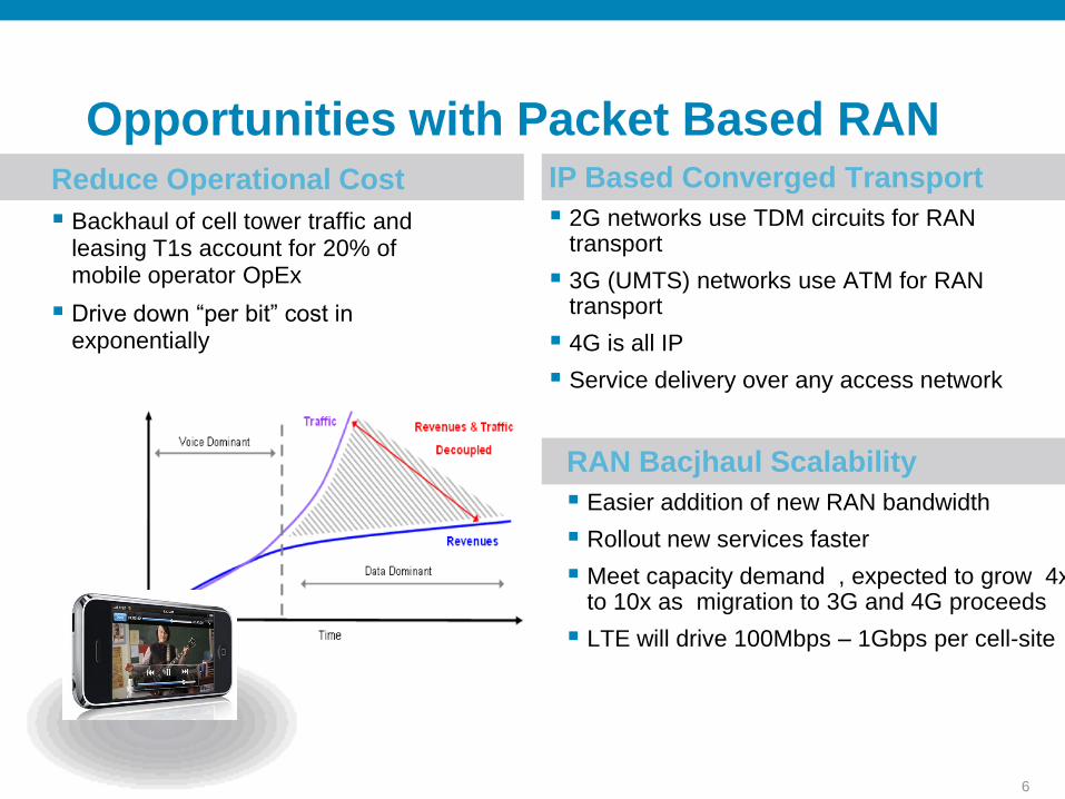
Opportunities with Packet Based RANReduce Operational Cost
Backhaul of cell tower traffic and leasing T1s account for 20% of mobile operator OpEx
Drive down “per bit” cost in exponentially
IP Based Converged Transport
2G networks use TDM circuits for RAN transport
3G (UMTS) networks use ATM for RAN transport
4G is all IP
Service delivery over any access network
RAN Bacjhaul Scalability
Easier addition of new RAN bandwidth
Rollout new services faster
Meet capacity demand , expected to grow 4x to 10x as migration to 3G and 4G proceeds
LTE will drive 100Mbps – 1Gbps per cell-site

7
Technical Requirements

8
Next-Gen Backhaul Requirements
Common and cheap transport
Generation and service independent
Traffic type awareness and prioritization (QoS)
Scalability
Service Resiliency
Clock distribution mechanism
Large scale provisioning and network visibility
Work with existing backhaul interfaces (T1/ATM/Sonet)
9
Mobile Operators Looking for Options
Convergence over ATM
RAN Optimization, with HSPA Offload
Microwave
Ethernet based BTS / Node-B
IP/MPLS based transport
Winner: IP/MPLS based transport
10
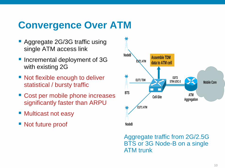
Convergence Over ATM
Aggregate 2G/3G traffic using single ATM access link
Incremental deployment of 3G with existing 2G
Not flexible enough to deliver statistical / bursty traffic
Cost per mobile phone increases significantly faster than ARPU
Multicast not easy
Not future proof
Aggregate traffic from 2G/2.5G BTS or 3G Node-B on a single ATM trunk
Cell-Site
Mobile Core
ATM Aggregation
E3/T3STM-1/OC-3E1/T1 TDM
E1/T1 ATM
NodeB
NodeB
BTS
Assemble TDM data to ATM cellE1/T1 ATM
11
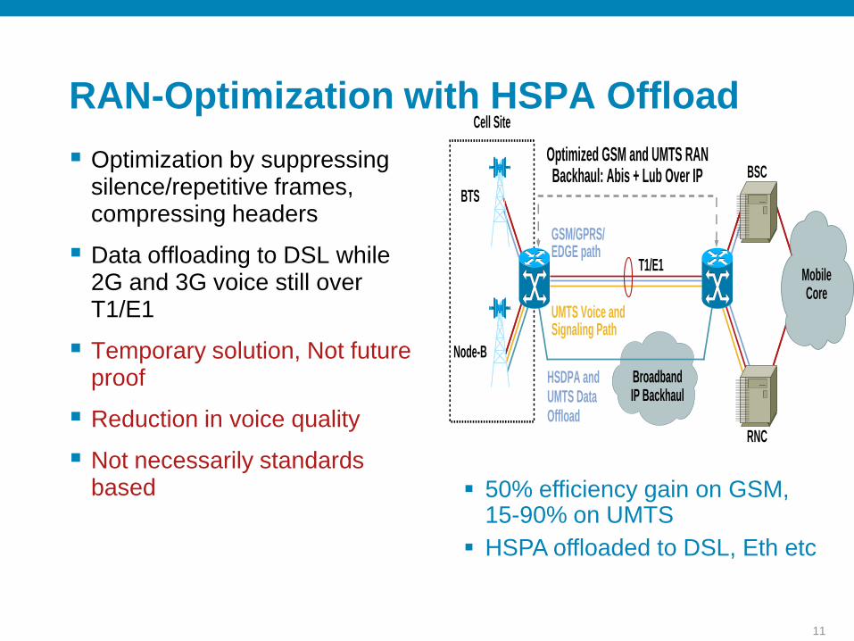
RAN-Optimization with HSPA Offload
Optimization by suppressing silence/repetitive frames, compressing headers
Data offloading to DSL while 2G and 3G voice still over T1/E1
Temporary solution, Not future proof
Reduction in voice quality
Not necessarily standards based
UMTS Voice and Signaling Path
GSM/GPRS/ EDGE path
HSDPA and UMTS Data Offload
Cell Site
BTS
Node-B
RNC
BSC
Mobile Core
Optimized GSM and UMTS RAN Backhaul: Abis + Lub Over IP
T1/E1
BroadbandIP Backhaul
50% efficiency gain on GSM, 15-90% on UMTS
HSPA offloaded to DSL, Eth etc

12
Microwave
Point to multipoint microwave radio links
On demand bandwidth allocation for Node-B’s
Nodal concept simplifies the end to end provisioning
Geography based limitations (Line of sight)
Spectrum / license availability
Requires contract renegotiations / new permits in buildings
Cheap until 16 E1 then cost goes up significantly

13
Ethernet Enabled NodeB
Makes data offloading easier
For voice traffic, NodeB must originate PWE
In most cases, basic ethernet connectivity –not sufficient for end-to-end reliable transport
Not necessarily standards based
RAN vendors have no MPLS legacy
Provisioning / troubleshooting MPLS advanced features on NodeB is a challenge
Subject to inherent security risks of IP / MPLS

14
IP/MPLS Based Transport
High capacity packet network
Access Agnostic
Unified transport
Widely deployed
Ethernet to cell site results in even more cost savings
Operational experience with their existing IP/MPLS core
Proven QoS, high availability and security
Clock synchronization over packet network is relatively new

15
RAN Architecture Evolution

16

17

18

19
Packet-Based RAN Concepts

20
Why is clocking important?
Data
Data
Reference A
Reference B
1 11
1 1
0 00
1 00 1
Reference Clocks
Out of Sync
Interpretation A
Interpretation B

21
Bad Clocking will………Result in slips on TDM interface to cell site or take the
interface down
Cell sites out of sync with rest of network can still initiate calls but handoffs will fail between cell towers (yes even in all IP- you need clocking because of this)

22
Not Stable
Not Accurate
Not Stable
Accurate Stable
Not Accurate
Stable
Precise
0
X
Time0
X
Time0
X
Time0
X
Time
Stable but
Not AccurateNot Stable and
Not Accurate
Not Stable
but Accurate
Stable
And Accurate
Frequency= Stability
Phase=Precision
Frequency and Phase Introduction
23
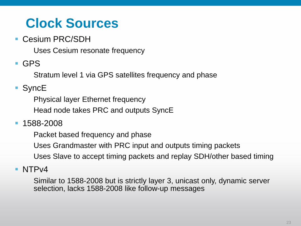
Clock Sources Cesium PRC/SDH
Uses Cesium resonate frequency
GPS
Stratum level 1 via GPS satellites frequency and phase
SyncE
Physical layer Ethernet frequency
Head node takes PRC and outputs SyncE
1588-2008
Packet based frequency and phase
Uses Grandmaster with PRC input and outputs timing packets
Uses Slave to accept timing packets and replay SDH/other based timing
NTPv4
Similar to 1588-2008 but is strictly layer 3, unicast only, dynamic server selection, lacks 1588-2008 like follow-up messages

24
Comparison of Stratum Levels
Stratum level is important from a clock source perspective since it drives the network clocking during normal ops
Stratum level is important from a clock receiver perspective since it drives the ability of the device to maintain frequency and phase during failure of the clock source
25
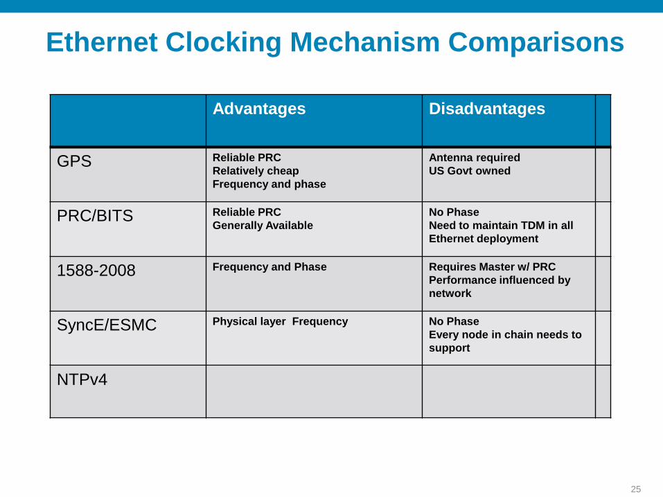
Advantages Disadvantages
GPS Reliable PRC
Relatively cheap
Frequency and phase
Antenna required
US Govt owned
PRC/BITS Reliable PRC
Generally Available
No Phase
Need to maintain TDM in all
Ethernet deployment
1588-2008 Frequency and Phase Requires Master w/ PRC
Performance influenced by
network
SyncE/ESMC Physical layer Frequency No Phase
Every node in chain needs to
support
NTPv4
Ethernet Clocking Mechanism Comparisons

26
Clock Deployment Guide
SyncE
Always use SyncE if possible if SDH or GPS clock is not available
End end SyncE support required (all nodes in chain have to support)
If all that is required is frequency, SyncE is sufficient and preferred

27
Clock Deployment Guide
1588-2008
Use if no SDH, GPS clock or SyncE for frequency
Packet Delay Variation (PDV) is your enemy. PDV is the variance in the delay of 1588 packets. The slave can not lock with excessive PDV. To minimize PDV:
Packets need to be L2 switched or L3 forwarded in HW
1588-2008 traffic must receive proper QoS prioritization
Tests have shown that any packets processed in a non dedicated CPU caused excessive PDV
28
Clock Deployment Guide
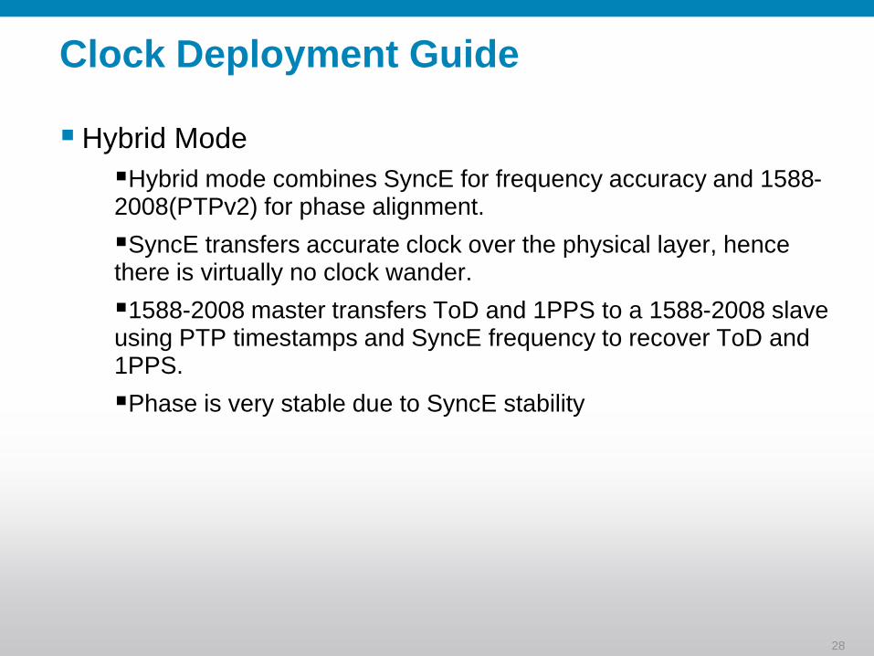
Hybrid Mode
Hybrid mode combines SyncE for frequency accuracy and 1588-2008(PTPv2) for phase alignment.
SyncE transfers accurate clock over the physical layer, hence there is virtually no clock wander.
1588-2008 master transfers ToD and 1PPS to a 1588-2008 slave using PTP timestamps and SyncE frequency to recover ToD and 1PPS.
Phase is very stable due to SyncE stability

29
Circuit Emulation Over Packet (CEoP)
Circuit Emulation = imitation of a physical communication link
CEoP imitates a physical communication link across Packet network
Allows the transport of any type of communication over Packet
Ideal for TDM or Leased Line replacement and legacy network consolidation
Packet Switched Network
TDM/ATM Circuits (ChSTM1/OC3, T1/E1 etc.)
TDM/ATM Circuits (ChSTM1/OC3, T1/E1 etc.)
Standards based CEoP

30
Pseudowire Types Used in RAN Transport
ATM pseudowire
Used for 3G only
Inefficient for a single cell but only sends traffic when required
Use of cell packing can reduce overhead with minimal impact on latency
TDM pseudowire
Used for 2G; can be used for 3G
Just as a real TDM circuit, bandwidth is wasted when the circuit is not being fully utilized.
For 3G networks an ATM pseudowire offers an advantage over a TDM pseudowire

31
Pseudowire Basics
Pseudowire (PW): A mechanism that carries the essential elements of an emulated service from one Device to one or more other Devices over a Packet Switched Network (PSN).
Within the context of PWE3, this uses IP or MPLS network as the mechanism for packet forwarding.
Having a common PW layer provides the simplification of deployment, management and provisioning.
Industry has GOOD experience deploying some of these PW types already, and the concept now can be extended to TDM & ATM for RAN purpose.
BSC/ RNC
MPLS
Attachment CircuitsAttachment Circuits
Pseudo-Wire
ATMoMPLS
TDMoMPLS
Node B/ BTS
TDMoMPLS – either SAToP or CESoPSN
SAToP : Structured Agnostic TDM over Packet : draft-ietf-pwe3-satop-05.txt , RFC-4553
CESoPSN : Circuit Emulation Services over Packet Switched Network : draft-ietf-pwe3-cesopsn-07.txt

32
SAToP Standards
RFC 4553: Structure-Agnostic Time Division Multiplexing (TDM) over Packet (SAToP)
This specification describes edge-to-edge emulation of the following TDM services described in [G.702]:
E1 (2048 kbit/s)
T1 (1544 kbit/s)
E3 (34368 kbit/s)
T3 (44736 kbit/s)
The protocol used for emulation of these services does not depend on the method in which attachment circuits are delivered to the PEs.

33
CESoPSN Standard
CESoPSN protocol designed to meet the following constrains:
Fixed amount of TDM data per packet: All the packets belonging to a given CESoPSN PW MUST carry the same amount of TDM data.
Fixed end-to-end delay: CESoPSN implementations SHOULD provide the same end-to-end delay between a given pair of CEs regardless of the bit-rate of the emulated service.
Packetization latency range:
SHOULD support packetization latencies in the range 1 to 5 milliseconds
Configurable packetization latency MUST allow granularity of 125 microseconds
Common data path for services with and without CE application signaling.
Structure-aware TDM Circuit Emulation Service over Packet Switched
Network (CESoPSN), draft-ietf-pwe3-cesopsn-06.txt

34
MPLS Core: Pseudo-Wire Signalling
C1
C2
xconnect <PE2> <VCID>
xconnect <PE1> <VCID>
Based on xconnect command, both PE’s will create
directed LDP session if doesn’t exist already
PE1
PE2
Directed LDP

35
MPLS Core: VC Label Distribution
VC1
VC2
xconnect <PE2> <VCID>
xconnect <PE1> <VCID>
PE1
PE2
NH: PE2
VC: VCID
Label: B
Circuit type: CEM
NH: PE1
VC: VCID
Label: A
Circuit type: CEM
CEM = SAToP E1, T1, E3, T3, CESoPSN basic, CESoPSN TDM with CAS
VC Label distributed through directed LDP session
FEC TLV tells the circuit type

36
LDP: Pseudo-Wire id FEC TLV
VC TLV = 128 or 0x80
VC Type: 0x0011 E1 (SaToP)
0x0012 T1 (SaToP)
0x0013 E3 (SaToP)
0x0014 T3 (SaToP)
0x0015 CESoPSN basic mode
0x0017 CESoPSN TDM with CAS
C: 1 control word present
Group ID: If for a group of VC, useful to withdraw many labels at once
VC ID : ID for the transported L2 vc
Int. Param: classical + IETF-PWE3-TDM-CP-Extension
VC TLV C VC Type VC info length
Group ID
VC ID
Interface Parameter

37
ATM / IMA Over Psuedowire
IMA terminated on Cell-site router.
ATM psuedowire between cell-site and aggregation router.
Aggregation router can map VCs from psuedowire to ATM OC3 Clear Channel towards RNC.
ATM VC mode allows VPI and VCI rewrite.
ATM VP mode allows VPI rewrite.
37
MPLS / IPMPLS / IP
ATM / IMA
ATM / IMA
ATM / OC3c
CSR41
CSR1
aggregation
Node-B
Node-B
RNC
MPLSL2 ATMMPLSControlMPLSL2 ATMMPLSControl

38
Native IP Over MPLS
38
Pure IP routing from eNode-B to MME/SGSN in the mobile core.
Utilize MPLS/IP core
Leased Eth or Own-built
Efficient to operate, avoids routing in the entire core
MPLS / IPMPLS / IP
IP
IP
IP
CSR
aggregation
eNodeB
eNodeB
MME
SGSN
IP
CSR

39
Redundancy @ Box-Level
Cell-site router redundancy
Redundant Power Supply
Aggregation router redundancy
Redundant Power Supply
Redundant Supervisor
Non-Stop Forwarding (NSF/SSO)
Redundant line-cards
Redundant aggregation device (optional)
Node BNode B
(U-PE)
(N-PE)(P) RNC
(ATM
IMA)(Gig-E or POS)
CEOP
(Clear
STM-1)
ATM
(N-PE)
CEOP
ATM
BSC
(Channel
STM-1)
(P)
(U-PE)
(Gig-E or POS)
Node BNode B
(E1)
BTS
MPLS

40
Redundancy @ Link-Level
Cell-site router redundancy
Multiple links to BTS / Node-B
T1 (TDM or IMA)
Eth
Multiple links to MPLS Core
Load-balanced
Aggregation router redundancy
Multiple links to BSC / RNC
Sonet (APS)
Eth (STP / Routing)
Multiple links to MPLS Core
Load-balanced
Node BNode B
(U-PE)
(N-PE)(P) RNC
(ATM
IMA)(Gig-E or POS)
CEOP
(Clear
STM-1)
ATM
(N-PE)
CEOP
ATM
BSC
(Channel
STM-1)
(P)
(U-PE)
(Gig-E or POS)
Node BNode B
(E1)
BTS
MPLS
41
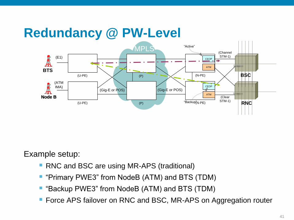
Redundancy @ PW-Level
Example setup:
RNC and BSC are using MR-APS (traditional)
“Primary PWE3” from NodeB (ATM) and BTS (TDM)
“Backup PWE3” from NodeB (ATM) and BTS (TDM)
Force APS failover on RNC and BSC, MR-APS on Aggregation router
Node BNode B
(U-PE)
(N-PE)(P) RNC
(ATM
IMA)(Gig-E or POS)
CEOP
(Clear
STM-1)
ATM
(N-PE)
CEOP
ATM
BSC
(Channel
STM-1)
(P)
(U-PE)
(Gig-E or POS)
Node BNode B
(E1)
BTS
MPLS
“PWE3 Redundancy: A Redundant L2 Connection both to the Active andBackup APS Interfaces on RNC and BSC”
Can be used for redundancy of adaptive clocking.
“Backup”
“Active”

42
Redundancy in MPLS Core
MPLS Core:
TE Fast Re-Route (FRR) – Link and Node
Tunnel selection
Well proven mechanisms
Leased or Built
Node BNode B
(U-PE)
(N-PE)(P) RNC
(ATM
IMA)(Gig-E or POS)
CEOP
(Clear
STM-1)
ATM
(N-PE)
CEOP
ATM
BSC
(Channel
STM-1)
(P)
(U-PE)
(Gig-E or POS)
Node BNode B
(E1)
BTS
MPLSLink Failure
Node Failure

43
Why QoS?
Latency – time taken for a packet to reach its destination
Jitter – change in inter-packet latency within a stream over time i.e. variation of latency
Packet loss – measure of packet loss between a source and destination
QoS provides:
Congestion Avoidance
Congestion Management
Prioritize critical traffic over best-effort
Signaling and Clocking <-> Voice <-> Real-time <-> Data
44
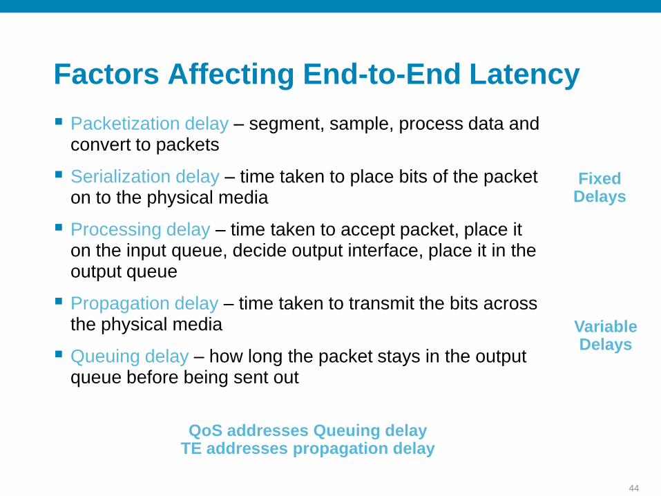
Factors Affecting End-to-End Latency
Packetization delay – segment, sample, process data and convert to packets
Serialization delay – time taken to place bits of the packet on to the physical media
Processing delay – time taken to accept packet, place it on the input queue, decide output interface, place it in the output queue
Propagation delay – time taken to transmit the bits across the physical media
Queuing delay – how long the packet stays in the output queue before being sent out
Fixed Delays
Variable Delays
QoS addresses Queuing delayTE addresses propagation delay

45
Proactive Approach –Measure Performance
Run IP SLA between the cell-site and Aggregation routers
Collect Latency, Jitter and Packet Loss
Source and Destination synced using NTP
T1 = origination timestamp
T2 = Arrival at destination timestamp
T3 = Departure (from destination) timestamp
P = (T3 – T2), processing delay at destination
T4 = Arrival at source timestamp
RTT = (T4 – T1 – P), round trip time
T1
T2
T3
T4
Source Destination
SLA Responder
Use IP SLA
46
Security
Service Provider Best practices for box-level security:
Lock-down VTYs, telnet
Disable unused services
Multiple bad password attempts
Protection from cell-site router hijack
ACLs on aggregation router
Control Plane Policing on aggregation router
Eavesdropping
3GPP has recommended using IPSEC security for signaling

47
Deployment Scenarios

48
CSRin a RAN Optimization deployment scenario
Optimized PW (GSMmux or UMTSmux) & MLPPP
RNC/BSCCell SiteBTS/Node-B
ATM/TDM MLPPP/E1 ATM/TDM
CSR ONSNode-B
BTS
MLPPP BundleBSC
RNC
Aggregation
TDM-ATM Short-haul & MLPPP Back-haulDeployment Scenario – 1

49
Deployment Scenario – 2
HSDPA Offload to DSL or CE
Optimized PW (GSMmux and UMTSmux) & MLPPP
Cell Site RNC/BSCBTS/Node-B
ATM/TDM MLPPP/E1 + DSL or CE ATM/TDM
HSDPA Offloaded
MLPPP BundleCSR ONS
BTS
Node-BBSC
RNC
Aggregation
HSDPA Offload & Hybrid Backhaul
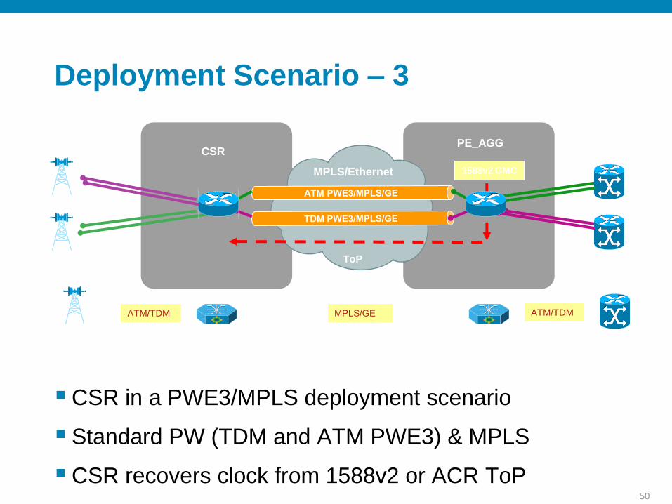
50
CSR in a PWE3/MPLS deployment scenario
Standard PW (TDM and ATM PWE3) & MPLS
CSR recovers clock from 1588v2 or ACR ToP
RNC/BSCCell SiteBTS/Node-B
ATM/TDM MPLS/GE ATM/TDM
CSRPE_AGGNode-B
BTS
MPLS/Ethernet
BSC
RNC
Aggregation
TDM-ATM Short-haul & MPLS BackhaulDeployment Scenario – 3
1588v2 GMC
ToP

51
Ethernet Node B & End to End L2 Transport
EoMPLS Pseudowire & EOAM features
Cell Site Distribution
802.1Q
GE/FE EoMPLS GE/10GE
Native IP L2
Native IP L2
Node-B
CSR PE_AGG
RNC
RNC
Ethernet Short-haul & L2 TransportDeployment Scenario – 4

52
Deployment Scenario – 5
Ethernet Node B & End to End L3 Transport
Fast Convergence IGP & BFD
Cell Site Distribution
FE/GE MPLS GE/10GE
Node-B RNC
CE/MPLS/IP
CSRNode-B
PE_AGG RNC
Ethernet Short-haul & L3 Transport

53
Deployment Scenario -6
Pre-Aggregation Site
IP/MPLS
Pseudowires
Node B
BTS
nxT1/E1
DACS
Node B
BTS
nxT1/E1
DACS
Class 5
(Wireline)
Class 5
(Wireline)
10 GE
10 GE
(2 x Ch. OC3)
(2 x Ch. OC3)
Pre-Agga and Agg Deployment with GE/10GE
Ready for ATM Backhaul
TDM Rooming and High Availability
Node B
BTS
nxT1/E1
DACS
Class 5
(Wireline)
(4 x Ch. OC3)
Pre-Aggregation Site
OC-3 Aggregation
Requirements:
MGW: 4 x OC3; (1+1)
BSC: 6 x OC3; (1+1)
RNC: 7 x OC3; (1+1)
DACS: 4 x OC3; (1+1)
BSC 1
RNC
Aggregation Site
MGW
(N x OC3)
(n x OC3)
(n x OC3)
(N x OC3)
BSC 2
BAYAMON
Jose Rosa (jrosa); Eduardo Quinones (equinone)

54
Mobile Backhaul Survey

5555
Backhaul Capacity Requirements at the Cell Site

5656
L1 Access Technologies: Global Estimate And Forecast

5757
Global Demand for Ethernet Backhaul to the Cell Site
27

5858
Regional Demand

5959
IP/Ethernet Interfaces At The Cell Site
34

60
"Hybrid" & "Pure" Ethernet Backhaul Architecture choices
60
36

61
Overall Design Procedure
Calculate bandwidth requirements for the cell-site and aggregation location
Choose the right “packet based RAN option / design”
MPLS Core – Leased or Built, customer dependant
Choose appropriate redundancy and connectivity between:
Cell-site router and Node-B / BTS
Aggregation router and RNC / BSC
Routing protocol between aggregation and cell-site routers
Ensure clocking / clock recovery at every node
Ensure resiliency for every failure type – link and node
Apply QoS and Security

62