packaged water chiller with screw compressors · pdf filecool stage (0 through 8 ... als air...
TRANSCRIPT

©1996 McQuay International
Packaged Water Chiller with Screw CompressorsModels: ALS125A thru 204A
ALS205A thru 280AALS300A thru 380APFS150A thru 200A
®
Installation and Maintenance Manual IM 549
Group: Chiller
Part Number: 5714335Y
Date: August 1996
2 IM 549
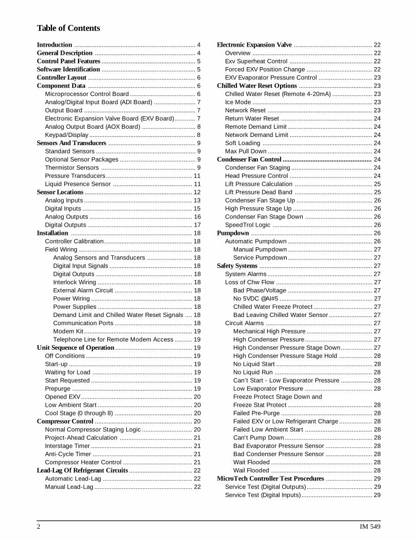
Table of Contents
Introduction ....................................................................... 4General Description ........................................................... 4Control Panel Features ....................................................... 5Software Identification ....................................................... 5Controller Layout ............................................................... 6Component Data ............................................................... 6
Microprocessor Control Board ...................................... 6Analog/Digital Input Board (ADI Board) ........................ 7Output Board ................................................................. 7Electronic Expansion Valve Board (EXV Board) ............ 7Analog Output Board (AOX Board) ............................... 8Keypad/Display .............................................................. 8
Sensors And Transducers ................................................... 9Standard Sensors .......................................................... 9Optional Sensor Packages ............................................ 9Thermistor Sensors ....................................................... 9Pressure Transducers .................................................. 11Liquid Presence Sensor .............................................. 11
Sensor Locations ............................................................... 12Analog Inputs ............................................................... 13Digital Inputs ................................................................ 15Analog Outputs ............................................................ 16Digital Outputs ............................................................. 17
Installation ....................................................................... 18Controller Calibration................................................... 18Field Wiring .................................................................. 18
Analog Sensors and Transducers .......................... 18Digital Input Signals ................................................ 18Digital Outputs ........................................................ 18Interlock Wiring ....................................................... 18External Alarm Circuit ............................................. 18Power Wiring ........................................................... 18Power Supplies ....................................................... 18Demand Limit and Chilled Water Reset Signals .... 18Communication Ports ............................................. 18Modem Kit ............................................................... 19Telephone Line for Remote Modem Access .......... 19
Unit Sequence of Operation ............................................. 19Off Conditions .............................................................. 19Start-up ........................................................................ 19Waiting for Load .......................................................... 19Start Requested ........................................................... 19Prepurge ...................................................................... 19Opened EXV ................................................................. 20Low Ambient Start ....................................................... 20Cool Stage (0 through 8) ............................................. 20
Compressor Control ......................................................... 20Normal Compressor Staging Logic ............................. 20Project-Ahead Calculation .......................................... 21Interstage Timer ........................................................... 21Anti-Cycle Timer .......................................................... 21Compressor Heater Control ........................................ 21
Lead-Lag Of Refrigerant Circuits ..................................... 22Automatic Lead-Lag .................................................... 22Manual Lead-Lag ......................................................... 22
Electronic Expansion Valve .............................................. 22Overview ...................................................................... 22Exv Superheat Control ................................................ 22Forced EXV Position Change ...................................... 22EXV Evaporator Pressure Control ............................... 23
Chilled Water Reset Options ........................................... 23Chilled Water Reset (Remote 4-20mA) ....................... 23Ice Mode ...................................................................... 23Network Reset ............................................................. 23Return Water Reset ..................................................... 24Remote Demand Limit ................................................. 24Network Demand Limit ................................................ 24Soft Loading ................................................................ 24Max Pull Down ............................................................. 24
Condenser Fan Control ................................................... 24Condenser Fan Staging ............................................... 24Head Pressure Control ................................................ 24Lift Pressure Calculation ............................................. 25Lift Pressure Dead Band ............................................. 25Condenser Fan Stage Up ............................................ 26High Pressure Stage Up .............................................. 26Condenser Fan Stage Down ....................................... 26SpeedTrol Logic .......................................................... 26
Pumpdown ....................................................................... 26Automatic Pumpdown ................................................. 26
Manual Pumpdown ................................................. 27Service Pumpdown ................................................. 27
Safety Systems .................................................................. 27System Alarms ............................................................. 27Loss of Chw Flow ........................................................ 27
Bad Phase/Voltage ................................................. 27No 5VDC @AI#5 ...................................................... 27Chilled Water Freeze Protect .................................. 27Bad Leaving Chilled Water Sensor ......................... 27
Circuit Alarms .............................................................. 27Mechanical High Pressure ...................................... 27High Condenser Pressure ....................................... 27High Condenser Pressure Stage Down.................. 27High Condenser Pressure Stage Hold ................... 28No Liquid Start ........................................................ 28No Liquid Run ......................................................... 28Can’t Start - Low Evaporator Pressure .................. 28Low Evaporator Pressure ....................................... 28Freeze Protect Stage Down andFreeze Stat Protect ................................................. 28Failed Pre-Purge ..................................................... 28Failed EXV or Low Refrigerant Charge ................... 28Failed Low Ambient Start ....................................... 28Can't Pump Down................................................... 28Bad Evaporator Pressure Sensor ........................... 28Bad Condenser Pressure Sensor ........................... 28Wait Flooded ........................................................... 28Wail Flooded ........................................................... 28
MicroTech Controller Test Procedures ........................... 29Service Test (Digital Outputs) ...................................... 29Service Test (Digital Inputs) ......................................... 29

IM 549 3
Keypad/Display ............................................................... 29Overview ...................................................................... 29Status Category ........................................................... 29Control Category ......................................................... 29Alarm Category ............................................................ 30Display Format ............................................................. 30
MicroTech Component Test Procedures & ALS Units ...... 30Status LED Diagnostics ............................................... 30
Red LED Remains On ............................................. 30Red and Green LEDs Off ........................................ 30
Troubleshooting Power Problems ............................... 30Troubleshooting Communications Problems ............. 31Troubleshooting the Keypad/Display Interface .......... 31
Display is Hard to Read .......................................... 31Back Light Not Lit ................................................... 31Display Is Blank or Garbled .................................... 31
Troubleshooting Analog Inputs ................................... 32Analog Input Not Read by the MCB ....................... 32
Troubleshooting Digital Inputs .................................... 32Digital Input Not Read by the MCB ........................ 32
Troubleshooting Analog Outputs ................................ 32Analog Output Device Is Not Operating Correctly ... 32
Troubleshooting Output Boards .................................. 33One LED Out ........................................................... 33All LEDs Out ............................................................ 33LED Lit, Output Not Energized ............................... 33Output Energized, LED Not Lit ............................... 33Contact Chatter ...................................................... 33
Troubleshooting Solid-State Relays............................ 34MCB Replacement ...................................................... 34Connecting The Communications Trunk .................... 35
Communications Cable Check ............................... 35Level-1 Controller Connection................................ 35Level-2 Controller Connection................................ 35
Keypad Key Functions ..................................................... 36Keypad Password ........................................................ 36Category Group ........................................................... 36Menu Group ................................................................. 37Item Group ................................................................... 37Action Group ................................................................ 37Example of Keypad Operation .................................... 37
Personal Computer Specification ..................................... 37MicroTech Menu Structure ............................................. 38
Status Menus ............................................................... 38Control Menus ............................................................. 38Alarm Menus ................................................................ 38
Schematics And Drawings ................................................ 60Control Cabinet Layout ............................................... 60Wiring Legend .............................................................. 63PFS Unit Control .......................................................... 64PFS 8-Stage Output .................................................... 65PFS MicroTech ............................................................ 66ALS Unit Control .......................................................... 67ALS 8-Stage Output .................................................... 68ALS MicroTech ............................................................ 69ALS Field Wiring .......................................................... 70

4 IM 549
Introduction
This manual provides installation, setup and troubleshootinginformation for the MicroTech controller provided on McQuayscrew compressor chillers. Please refer to installation manualIM548 for unit application information as well as water andrefrigerant piping details. All operating descriptions con-tained in this manual are based on MicroTech controllersoftware version SC2-X18B, SC3XX19 and SC4XX19A. Chilleroperating characteristics and menu selections may vary withother versions of controller software. Contact McQuayServicefor software update information.
CAUTIONThis equipment generates, uses and can radiate radiofrequency energy and if not installed and used in accor-dance with the instructions manual, may cause interfer-ence to radio communications. It has been tested andfound to comply with the limits for a class A digitaldevice, pursuant to part 15 of the FCC rules. Theselimits are designed to provide reasonable protectionagainst harmful interference when the equipment isoperated in a commercial environment.
Operation of this equipment in a residential area islikely to cause harmful interference in which case theuser will be required to correct the interference at hisown expense. McQuay International disclaims any li-ability resulting from any interference or for the correc-tion thereof.
The MicroTech controller is designed to operate within anambient temperature range of minus 40 to plus 185°F and amaximum relative humidity of 95% (non-condensing).
General Description
The MicroTech Unit Control Panel, available on all McQuayALS and PFS products, contains a Model 250 Microproces-sor based controller which provides all monitoring andcontrol functions required for the safe, efficient operation ofthe unit. The operator can monitor all operating conditions byusing the panel’s built in 2 line by 16 character display andkeypad or by using an IBM compatible computer runningMcQuay Monitor software. In addition to providing all normaloperating controls, the MicroTech controller monitors allsafety devices on the unit and will shut the system down andclose a set of alarm contacts if an alarm condition develops.
Important operating conditions at the time an alarm occursare retained in the controller’s memory to aid in troubleshoot-ing and fault analysis. The system is protected by a passwordscheme which only allows access by authorized personnel.A valid password must be entered into the panel keypad bythe operator before any set points may be altered.
Unit IdentificationALS Air Cooled Chiller with Screw CompressorsPFS Water Cooled Chiller with Screw Compressors
CAUTIONThe McQuay MicroTech control panel contains staticsensitive components. A static discharge while han-dling electronic circuit boards may cause damage tothe components.
To prevent such damage during service involvingboard replacement, McQuay recommends dischargingany static electrical charge by touching the bare metalinside the panel before performing any service work.
CAUTIONExcessive moisture in the control panel can causehazardous working conditions and improper equip-ment operation.
When servicing equipment during rainy weather con-ditions, the electrical devices and MicroTech compo-nents housed in the main control panel must beprotected.
Table 1.
!
!
!

IM 549 5
SC 3 2 E 19 A
Control Panel Features
Flexible control of leaving chilled water with convenientreset capability.
Enhanced head pressure control on air cooled unitsresulting in increased total unit SEER.
Convenient, easy to read 2 line by 16 character display forplain English readout of operating temperatures andpressures, operating modes or alarm messages.
Keypad adjustment of unit safeties such as low watertemperature cutout, high pressure cutout, suction pres-sure cutout, and freeze protection. The operator can usethe keypad to monitor various operating conditions, setpoints or alarm messages.
Security password protection against unauthorized chang-ing of set points and other control parameters.
Complete plain English diagnostics to inform the operatorof system warnings and alarms. All alarms are time anddate stamped so there is no guessing of when the alarm
condition occurred. In addition, the operating conditionsthat existed at the instant of shutdown can be recalled toaid in isolating the cause of the problem.
Soft loading feature to reduce electrical consumption andpeak demand charges during chilled water loop pulldown.
Easy integration into building automation systems viaseparate 4-20 milliamp signals for chilled water reset anddemand limiting. McQuay’s Open Protocol feature is fullysupported.
Flexible internal time clock for on/off scheduling.
Communications capabilities for local system monitoring,changing of set points, trend logging, remote reset, alarmand event detection, via IBM compatible PC. The optionalmodem kit supports the same features from an off-site PCrunning McQuay Monitor software.
Special service modes may be used to override automaticunit staging during system checkout and service.
Software Identification
Controller software is factory installed and tested in eachpanel prior to shipment. The software is identified by aprogram code which is printed on a small label attached tothe controller. The software version may also be displayedon the keypad/display by viewing the last menu item in theMisc. Setup menu.
The software “version” is the 5th & 6th digit of the softwarenumber. In the example, the version is “17” and the revisionto the software is “G”.
Revisions are released in alphabetical order.
Screw Chiller
Number of Compressors
RefrigerantType 2 = R22Type 3 = R134a
Revision
Version
English
Hardware Software

6 IM 549
Controller LayoutAll major MicroTech components are mounted inside thecontrol section side of the unit’s control cabinet. The indi-vidual components are interconnected by ribbon cables,shielded multi-conductor cables or discrete wiring. Powerfor the system is provided by transformers T-2 and T-4. Allfield wiring must enter the control cabinet through the
knockouts provided and be terminated on field wiring termi-nal strips. The standard ALS keypad/display is located insidethe control cabinet for protection from the weather while thePFS Keypad/Display is accessible through the exterior of thecontrol cabinet. See Figure 1 for typical control cabinet layout.
Figure 1. Typical control cabinet layout — 2 compressor unit
Component Data
Microprocessor Control Board (MCB1)The Model 250 Microprocessor Control Board contains theelectronic hardware and software required to monitor andcontrol the unit. It receives input from the ADI Board andsends commands to the Output Board to maintain the unit’soptimum operating mode for the current conditions. Statuslights are mounted on the control board to indicate theoperating condition of the microprocessor.
Figure 2. MCB1
Keypad
Mech. relays F1 CB F2
NB
ADX EXV
Low voltage wireway
High voltage wireway
Mod
em
MDBI ADI
Low voltage wireway
Low voltage wireway
TB4 TB5
RE
S1
SC
GD
1
GD
2
T4
T8
T2
T7
Hig
h vo
ltag
ew
irew
ay
Low voltage wireway
Hig
h vo
ltag
e w
irew
ay
Low
vo
ltag
e w
irew
ay Outputboard
TB
3T
B2
FB11FB10FB9FB8FB7FB6
T1
FB5
GRD
M11 M12 M13 M15 M23 M25T10
M21 M22 M14 M24CT1
PB1
GFPS
GFPR
OL5 OL1 OL2 OL6
CB5 CB1 CB2PVM CB6
M5 M1C1 C2
M2 M6Fax alarm
option

IM 549 7
Analog/Digital Input Board (ADI Board)The ADI Board provides low voltage power for the tempera-ture and pressure sensors. It also provides electrical isola-tion between the Microprocessor Control Board and all 24Vswitch inputs. LEDs are furnished on the board to give a
visual indication of the status of all digital inputs. All analogand digital signals from sensors, transducers and switchesare received by the ADI Board and then sent to the Micropro-cessor Control Board for interpretation.
Output BoardThe Output Board contains up to 24 solid state relays whichare used to control all compressors, condenser fans, sole-noid valves and alarm annunciation.
Figure 4. Output board
It receives control signals from the Microprocessor Con-trol Board through a 50 conductor ribbon cable.
Electronic Expansion Valve Board (EXV Board)Each EXV Board will directly control up to two electronicexpansion valves. The boards may be cascaded together for
Figure 5. EXV board
units with more than two EXV’s. Control instructions for theboard are generated by the M250 controller.
Figure 3. ADI

8 IM 549
Analog Output Board (AOX Board) (With Optional SpeedTrol)The AOX Board converts control instructions from the M250’sexpansion bus into an analog control signal suitable for
Figure 6. AOX board
driving a variable speed condenser fan. Each AOX Board isfactory set via jumper to provide an output signal of 0 - 10 VDC.
Keypad/DisplayThe Keypad/Display is the primary operator interface to theunit. All operating conditions, system alarms and set pointscan be monitored from this display and all adjustable set
Figure 7. Keypad display
points can be modified from this keyboard if the operator hasentered a valid operator password.

IM 549 9
Sensors and Transducers
Standard SensorsEvaporator Leaving Water TemperatureEvaporator Refrigerant Pressure, Circuit #1, 2, 3 & 4Condenser Refrigerant Pressure, Circuit #1, 2, 3 & 4Saturated Suction Temperature, Circuit #1, 2, 3 & 4
Liquid Line Temperature, Circuit #1, 2, 3 & 4(Provides direct display of subcooling and superheat)Entering Evaporator Water TemperatureAmbient O.A. Temperature
Optional Sensor PackagesWater cooled units only:Entering Condenser Water TemperatureLeaving Condenser Water Temperature
Air and water cooled units:Percent Unit Amps on 2 Compressor Units(Percent total unit amperage including compressors andcondenser fans. Does not include externally powered equip-ment such as water pumps.)
Percent Compressor Amps On 3 Compressor Units AndPercent Circuit Amps (1 & 3, 2 & 4) On 4 Compressor Units.
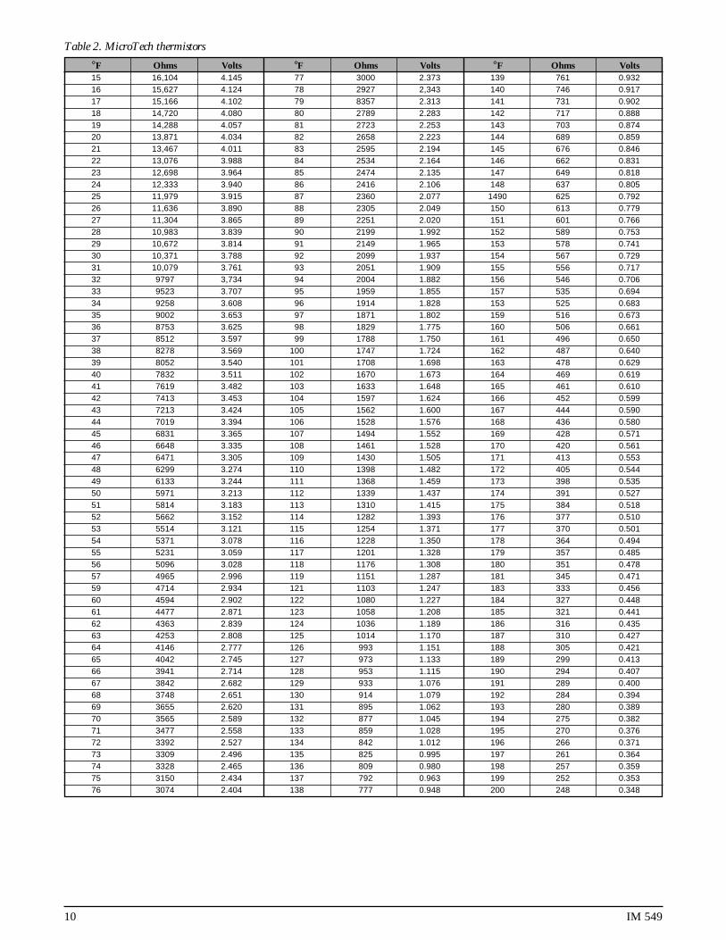
Thermistor SensorsMicroTech panels use a negative temperature coefficientthermistor for temperature sensing. A normal sensor willmeasure 3000 ohms at 77°F.
Figure 8. Thermistor sensor
Stainless steeltubing
PottingThermistor
Shieldedcable
10 IM 549
Table 2. MicroTech thermistors
°F Ohms Volts °F Ohms Volts °F Ohms Volts15 16,104 4.145 77 3000 2.373 139 761 0.93216 15,627 4.124 78 2927 2,343 140 746 0.91717 15,166 4.102 79 8357 2.313 141 731 0.90218 14,720 4.080 80 2789 2.283 142 717 0.88819 14,288 4.057 81 2723 2.253 143 703 0.87420 13,871 4.034 82 2658 2.223 144 689 0.85921 13,467 4.011 83 2595 2.194 145 676 0.84622 13,076 3.988 84 2534 2.164 146 662 0.83123 12,698 3.964 85 2474 2.135 147 649 0.81824 12,333 3.940 86 2416 2.106 148 637 0.80525 11,979 3.915 87 2360 2.077 1490 625 0.79226 11,636 3.890 88 2305 2.049 150 613 0.77927 11,304 3.865 89 2251 2.020 151 601 0.76628 10,983 3.839 90 2199 1.992 152 589 0.75329 10,672 3.814 91 2149 1.965 153 578 0.74130 10,371 3.788 92 2099 1.937 154 567 0.72931 10,079 3.761 93 2051 1.909 155 556 0.71732 9797 3,734 94 2004 1.882 156 546 0.70633 9523 3.707 95 1959 1.855 157 535 0.69434 9258 3.608 96 1914 1.828 153 525 0.68335 9002 3.653 97 1871 1.802 159 516 0.67336 8753 3.625 98 1829 1.775 160 506 0.66137 8512 3.597 99 1788 1.750 161 496 0.65038 8278 3.569 100 1747 1.724 162 487 0.64039 8052 3.540 101 1708 1.698 163 478 0.62940 7832 3.511 102 1670 1.673 164 469 0.61941 7619 3.482 103 1633 1.648 165 461 0.61042 7413 3.453 104 1597 1.624 166 452 0.59943 7213 3.424 105 1562 1.600 167 444 0.59044 7019 3.394 106 1528 1.576 168 436 0.58045 6831 3.365 107 1494 1.552 169 428 0.57146 6648 3.335 108 1461 1.528 170 420 0.56147 6471 3.305 109 1430 1.505 171 413 0.55348 6299 3.274 110 1398 1.482 172 405 0.54449 6133 3.244 111 1368 1.459 173 398 0.53550 5971 3.213 112 1339 1.437 174 391 0.52751 5814 3.183 113 1310 1.415 175 384 0.51852 5662 3.152 114 1282 1.393 176 377 0.51053 5514 3.121 115 1254 1.371 177 370 0.50154 5371 3.078 116 1228 1.350 178 364 0.49455 5231 3.059 117 1201 1.328 179 357 0.48556 5096 3.028 118 1176 1.308 180 351 0.47857 4965 2.996 119 1151 1.287 181 345 0.47159 4714 2.934 121 1103 1.247 183 333 0.45660 4594 2.902 122 1080 1.227 184 327 0.44861 4477 2.871 123 1058 1.208 185 321 0.44162 4363 2.839 124 1036 1.189 186 316 0.43563 4253 2.808 125 1014 1.170 187 310 0.42764 4146 2.777 126 993 1.151 188 305 0.42165 4042 2.745 127 973 1.133 189 299 0.41366 3941 2.714 128 953 1.115 190 294 0.40767 3842 2.682 129 933 1.076 191 289 0.40068 3748 2.651 130 914 1.079 192 284 0.39469 3655 2.620 131 895 1.062 193 280 0.38970 3565 2.589 132 877 1.045 194 275 0.38271 3477 2.558 133 859 1.028 195 270 0.37672 3392 2.527 134 842 1.012 196 266 0.37173 3309 2.496 135 825 0.995 197 261 0.36474 3328 2.465 136 809 0.980 198 257 0.35975 3150 2.434 137 792 0.963 199 252 0.35376 3074 2.404 138 777 0.948 200 248 0.348

IM 549 11
Pressure TransducersThese transducers are selected for a specific operatingrange and provide an output signal which is proportional tothe sensed pressure. The typical range for evaporator sen-sors is 0 to 150 psig with a resolution of 0.1 psig. Condenserpressure sensors have a range of 0 to 450 psi and a resolution
Figure 9.
of 0.5 psig. The pressure transducers require an external 5VDC power supply to operate which is provided by theMicroTech controller. This connection should not be used topower any additional devices.
Liquid Presence SensorThe presence of liquid refrigerant is determined by a liquidlevel sensor mounted at the liquid injection port in thecompressor casting. Whenever the glass prism sensor tip is
Figure 10.
in contact with liquid, the sensor output signal will be high(>7VAC). If no liquid is detected, the output will be low(0VAC).
Red dot – condenserBlue dot – evaporator

12 IM 549
Sensor Locations – 2 Compressor Unit
Sensor Description PartNumber
S00 Evaporator Leaving Water Temperature 605830-03S01 Evaporator Pressure Transducer Circuit #1 658168B-011S02 Evaporator Pressure Transducer Circuit #2 658168B-011S03 Condenser Pressure Transducer Circuit #1 658168B-021S04 Condenser Pressure Transducer Circuit #2 658168B-021
S06 Evaporator Water Temperature Reset N/A(Outdoor Air or Zone)
S07 Demand Limit N/AS08 Evaporator Entering Water Temperature 705830B-02
S09 Condenser Entering Water Temperature 705830B-01(or Outside Air)
S11 Total Unit AmpsS12 Suction Temperature Circuit #1 705830B-02S13 Suction Temperature Circuit #2 705830B-01S14 Liquid Line Temperature Circuit #1 705830B-01S15 Liquid Line Temperature Circuit #2 705830B-02
Table 3.
Figure 11.
Inside ofcontrol boxon power& control
panels
Back ofcontrol box
Out
S00S08 S12 S03 S01 S14
S09
S11
S15S04S02S13
IM 549 13
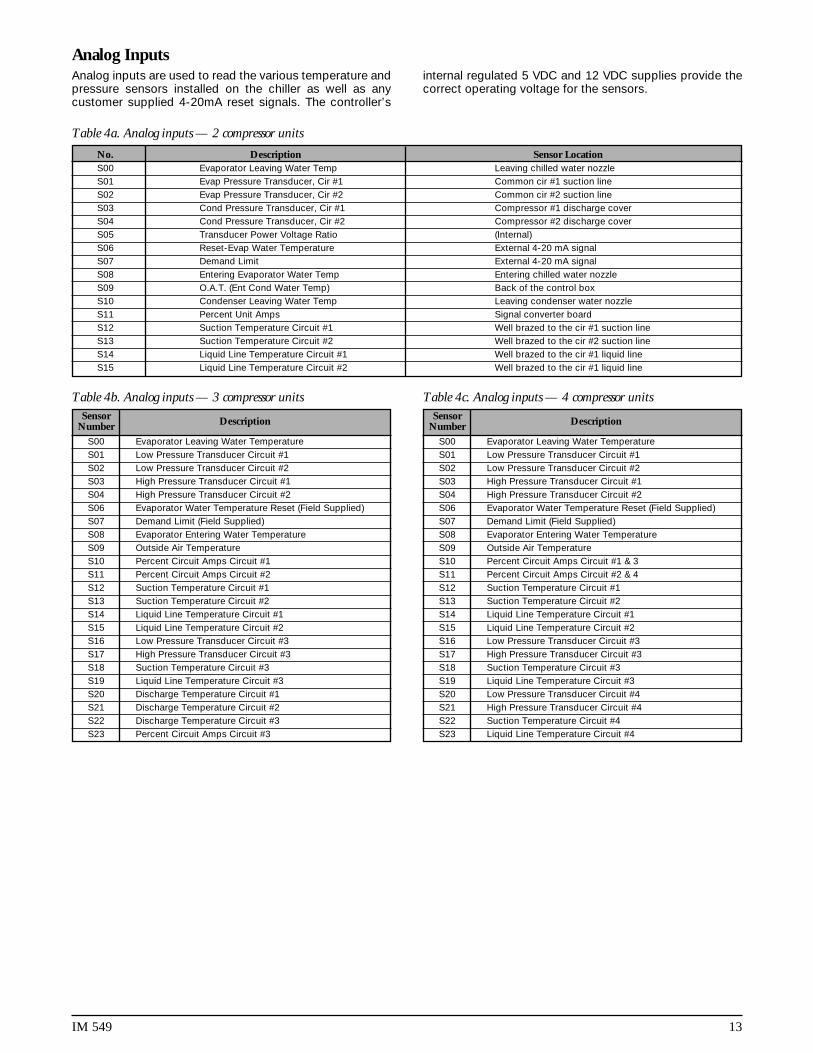
Analog InputsAnalog inputs are used to read the various temperature andpressure sensors installed on the chiller as well as anycustomer supplied 4-20mA reset signals. The controller’s
internal regulated 5 VDC and 12 VDC supplies provide thecorrect operating voltage for the sensors.
Sensor DescriptionNumberS00 Evaporator Leaving Water TemperatureS01 Low Pressure Transducer Circuit #1S02 Low Pressure Transducer Circuit #2S03 High Pressure Transducer Circuit #1S04 High Pressure Transducer Circuit #2S06 Evaporator Water Temperature Reset (Field Supplied)S07 Demand Limit (Field Supplied)S08 Evaporator Entering Water TemperatureS09 Outside Air TemperatureS10 Percent Circuit Amps Circuit #1S11 Percent Circuit Amps Circuit #2S12 Suction Temperature Circuit #1S13 Suction Temperature Circuit #2S14 Liquid Line Temperature Circuit #1S15 Liquid Line Temperature Circuit #2S16 Low Pressure Transducer Circuit #3S17 High Pressure Transducer Circuit #3S18 Suction Temperature Circuit #3S19 Liquid Line Temperature Circuit #3S20 Discharge Temperature Circuit #1S21 Discharge Temperature Circuit #2S22 Discharge Temperature Circuit #3S23 Percent Circuit Amps Circuit #3
Table 4b. Analog inputs — 3 compressor unitsSensor DescriptionNumber
S00 Evaporator Leaving Water TemperatureS01 Low Pressure Transducer Circuit #1S02 Low Pressure Transducer Circuit #2S03 High Pressure Transducer Circuit #1S04 High Pressure Transducer Circuit #2S06 Evaporator Water Temperature Reset (Field Supplied)S07 Demand Limit (Field Supplied)S08 Evaporator Entering Water TemperatureS09 Outside Air TemperatureS10 Percent Circuit Amps Circuit #1 & 3S11 Percent Circuit Amps Circuit #2 & 4S12 Suction Temperature Circuit #1S13 Suction Temperature Circuit #2S14 Liquid Line Temperature Circuit #1S15 Liquid Line Temperature Circuit #2S16 Low Pressure Transducer Circuit #3S17 High Pressure Transducer Circuit #3S18 Suction Temperature Circuit #3S19 Liquid Line Temperature Circuit #3S20 Low Pressure Transducer Circuit #4S21 High Pressure Transducer Circuit #4S22 Suction Temperature Circuit #4S23 Liquid Line Temperature Circuit #4
Table 4c. Analog inputs — 4 compressor units
No. Description Sensor LocationS00 Evaporator Leaving Water Temp Leaving chilled water nozzleS01 Evap Pressure Transducer, Cir #1 Common cir #1 suction lineS02 Evap Pressure Transducer, Cir #2 Common cir #2 suction lineS03 Cond Pressure Transducer, Cir #1 Compressor #1 discharge coverS04 Cond Pressure Transducer, Cir #2 Compressor #2 discharge coverS05 Transducer Power Voltage Ratio (Internal)S06 Reset-Evap Water Temperature External 4-20 mA signalS07 Demand Limit External 4-20 mA signalS08 Entering Evaporator Water Temp Entering chilled water nozzleS09 O.A.T. (Ent Cond Water Temp) Back of the control boxS10 Condenser Leaving Water Temp Leaving condenser water nozzleS11 Percent Unit Amps Signal converter boardS12 Suction Temperature Circuit #1 Well brazed to the cir #1 suction lineS13 Suction Temperature Circuit #2 Well brazed to the cir #2 suction lineS14 Liquid Line Temperature Circuit #1 Well brazed to the cir #1 liquid lineS15 Liquid Line Temperature Circuit #2 Well brazed to the cir #1 liquid line
Table 4a. Analog inputs — 2 compressor units

14 IM 549
Sensor Locations – 3 Screw Compressor Unit
Sensor Locations – 4 Screw Compressor Unit

IM 549 15
Digital Inputs
Note: All digital inputs are 24 VAC.At 7.5 VAC to 24 VAC the digital input contacts are
considered closed, and the signal level is high.Below 7.5 VAC, the contacts are considered open, and
the signal level is low.
Table 5a. Digital inputs — 2 compressor unit
Number Description Lo Signal Hi Signal0 Mechanical High Pressure Switch, Circuit #1 Alarm Normal1 Liquid Presence Switch, Compressor #1 Alarm Normal2 Motor Protect, Compressor #1 Alarm Normal3 Oil Level Sensor, Compressor #1 Alarm Normal4 (Reserved)5 System Switch (S1) Stop Run6 Phase Voltage Monitor Alarm Normal7 Pump Down Switch, Circuit #1 Normal Pumpdown8 Mechanical High Pressure Switch, Circuit #2 Alarm Normal9 Liquid Presence Switch, Compressor #2 Alarm Normal
10 Motor Protect, Compressor #2 Alarm Normal11 Oil Level Sensor, Compressor #2 Alarm Normal12 (Reserved)13 Unit Remote Stop Switch Stop Run14 Evap Water Flow Switch Alarm Normal15 Pump Down Switch, Circuit #2 Normal Pumpdown
No. Description Led Off Led On
0 Mechanical High Pressure Switch, Cir #1 Alarm Normal1 Liquid Presence Sensor Compr #1 No Liquid Liquid2 Motor Prot Compr #1 Alarm Normal3 Not Used — —4 Not Used — —5 System On-Off Switch Off On6 Phase Volt Monitor Compr #1 Alarm Normal7 PumpDown Switch Compr #1 Normal Pump DN8 Mechanical High Pressure Switch Cir #2 Alarm Normal9 Liquid Presence Sensor Compr #2 No Liquid Liquid
10 Motor Prot Compr #2 Alarm Normal11 Not Used — —12 Not Used — —13 Remote Start Stop Switch Stop Start14 Evap Water Flow Switch No Flow Flow15 PumpDown Switch Compr #2 Normal PumpDn16 Mechanical High Pressure Switch Cir #3 Alarm Normal17 Liquid Presence Sensor Compr #3 No Liquid Liquid18 Motor Prot Compr #3 Alarm Normal19 Not Used — —20 Not Used — —21 Phase Volt Monitor Compr #2 Alarm Normal22 Phase Volt Monitor Compr #3 Alarm Normal23 PumpDown Switch Compr #3 Alarm Normal
Table 5b. Digital inputs — 3 compressor unit

16 IM 549
No. Description Led Off Led On
0 Mechanical High Pressure Switch, Cir #1 Alarm Normal1 Liquid Presence Sensor Compr #1 No Liquid Liquid2 Motor Prot Compr #1 Alarm Normal3 Not Used — —4 Not Used — —5 System On-Off Switch Off On6 Phase Volt Monitor Compr #1 Alarm Normal7 PumpDown Switch Compr #1 Normal Pump DN8 Mechanical High Pressure Switch Cir #2 Alarm Normal9 Liquid Presence Sensor Compr #2 No Liquid Liquid
10 Motor Prot Compr #2 Alarm Normal11 Not Used — —12 Not Used — —13 Remote Start Stop Switch Stop Start14 Evap Water Flow Switch No Flow Flow15 PumpDown Switch Compr #2 Normal PumpDn16 Mechanical High Pressure Switch Cir #3 Alarm Normal17 Liquid Presence Sensor Compr #3 No Liquid Liquid18 Motor Prot Compr #3 Alarm Normal19 Not Used — —20 Not Used — —21 Phase Volt Monitor Multi Point Alarm Normal22 Not Used — —23 PumpDown Switch Compr #3 Normal PumpDn
0 Mechanical High Pressure Switch Cir #4 Alarm Normal1 Liquid Presence Sensor Compr #4 No Liquid Liquid2 Motor Prot Compr #4 Alarm Normal3 Not Used — —4 Not Used — —5 Not Used — —6 Not Used — —7 PumpDown Switch Compr #4 Normal PumpDn
Analog Outputs
Table 6. Analog outputs
No. Description Signal Range0 SpeedTrol, Circuit #1 0-10 VDC1 SpeedTrol, Circuit #2 0-10 VDC2 SpeedTrol, Circuit #3 0-10 VDC3 SpeedTrol, Circuit #4 0-10 VDC
Table 5c. Digital inputs — 4 compressor unit

IM 549 17
Table 7b. Digital outputs — 3 compressor unit Table 7c. Digital outputs — 4 compressor unit
Digital OutputsTable 7a. Digital outputs — 2 compressor unit
Relay Description0 Alarm Circuit1 Chilled Water Pump Relay2 EXV Control3 EXV Control4 Compr #1 Contactor5 Compr #1 Top Solenoid Valve6 Compr #1 Bottom Right Solenoid Valve (feed)7 Compr #1 Bottom Left Solenoid Valve (vent)8 Compr #2 Contactor9 Compr #2 Top Solenoid Valve (feed)
10 Compr #2 Bottom Right Solenoid Valve (feed)11 Compr #2 Bottom Left Solenoid Valve (vent)12 Condenser Fan Contactor M-1213 Condenser Fan Contactor M-1314 Condenser Fan Contactor M-1415 Condenser Fan Contactor M-1516 Condenser Fan Contactor M-2217 Condenser Fan Contactor M-2318 Condenser Fan Contactor M-2419 Condenser Fan Contactor M-2520 Compr #3 Contactor21 Compr #3 Top Solenoid Valve (feed)22 Compr #3 Bottom Right Solenoid Valve (feed)23 Compr #3 Bottom Left Solenoid Valve (vent)24 Condenser Fan Contactor M-3225 Condenser Fan Contactor M-3326 Condenser Fan Contactor M-3427 Condenser Fan Contactor M-3528 Hot Gas Bypass - SV529 Hot Gas Bypass - SV6
Relay Description0 Alarm Circuit1 Chilled Water Pump Relay2 EXV Control3 EXV Control4 Compr #1 Contactor5 Compr #1 Top Solenoid Valve6 Compr #1 Bottom Right Solenoid Valve (feed)7 Compr #1 Bottom Left Solenoid Valve (vent)8 Compr #2 Contactor9 Compr #2 Top Solenoid Valve (feed)
10 Compr #2 Bottom Right Solenoid Valve (feed)11 Compr #2 Bottom Left Solenoid Valve (vent)12 Condenser Fan Contactor M-1213 Condenser Fan Contactor M-1314 Condenser Fan Contactor M-1415 Condenser Fan Contactor M-1516 Condenser Fan Contactor M-2217 Condenser Fan Contactor M-2318 Condenser Fan Contactor M-2419 Condenser Fan Contactor M-2520 Compr #3 Contactor21 Compr #3 Top Solenoid Valve (feed)22 Compr #3 Bottom Right Solenoid Valve (feed)23 Compr #3 Bottom Left Solenoid Valve (vent)24 Condenser Fan Contactor M-3225 Condenser Fan Contactor M-3326 Condenser Fan Contactor M-3427 Condenser Fan Contactor M-3528 Hot Gas Bypass — SV529 Hot Gas Bypass — SV630 Not Used31 Compr #4 Contactor32 Compr #4 Top Solenoid Valve (feed)33 Compr #4 Bottom Right Solenoid Valve (feed)34 Compr #4 Bottom Left Solenoid Valve (vent)35 Condenser Fan Contactor M-4236 Condenser Fan Contactor M-4237 Condenser Fan Contactor M-4238 Condenser Fan Contactor M-42
No. Description Off On0 Alarm LED and Contact (Programmable) (Programmable)1 Chilled Water Pump Stop Run2 EXV Serial Data 13 EXV Serial Data 24 MCR relay, Compr #1 Stop Run5 Top Solenoid, Compr #1 Hold Load6 Bottom Right Solenoid, Compr #1 Hold Load7 Bottom Left Solenoid, Compr #1 Hold Load8 MCR Relay, Compr #2 Stop Run9 Top Solenoid, Compr #2 Hold Load
10 Bottom Right Solenoid, Compr #2 Hold Unload11 Bottom Left Solenoid, Compr #2 Hold Load12 Condenser Fan #1, Circ #1 (M12) Off On13 Condenser Fan #2, Circ #1 (M13) Off On14 Condenser Fan #3, Circ #1 (M14) Off On15 Condenser Fan #4, Circ #1 (M15) Off On16 Condenser Fan #1, Circ #2 (M22) Off On17 Condenser Fan #2, Circ #2 (M23) Off On18 Condenser Fan #3, Circ #2 (M24) Off On19 Condenser Fan #4, Circ #2 (M25) Off On20 Liquid Solenoid Valve, Cir #1 Close Open21 Liquid Solenoid Valve, Cir #2 Close Open22 (Spare)23 (Spare)

18 IM 549
Installation
Controller CalibrationThe control software is installed and tested by the factoryprior to shipping therefore no periodic calibration of thecontroller is required. All control and safety set points will bechecked and adjusted if necessary by the McQuayService
start-up technician prior to starting the unit. The MicroTechcontroller contains default set points which will be appropri-ate for most common installations.
Field WiringAnalog sensors and transducersAll sensors and transducers required for normal chiller op-eration are installed and wired by the factory. Any optionalanalog signals provided by the installing contractor requiretwisted, shielded pair wire (Belden #8760 or equal).
Digital input signalsRemote contacts for all digital inputs such as the chilledwater flow switch and the remote start/stop switch must bedry contacts suitable for the 24 VAC control signals pro-duced by the screw chiller control panel.
Digital outputsDevices wired to the digital outputs typically be an optionalChilled Water Pump control relay or an Alarm Annunciator.The MicroTech output device is a normally open solid staterelay with an on board, replaceable 5 amp fuse. The model250 controller activates a solid state relay by sending a“trigger” signal to the output board via the attached ribboncable. The relay responds to the trigger by lowering it’sresistance which allows current to flow through its “con-tacts”. When the controller removes the trigger signal, therelay’s resistance becomes very high, causing the currentflow to stop. The status of all outputs are shown by individualred LEDs for ease of determining output status.
Interlock wiringAll interlock wiring to field devices such as flow switches andpump starters is provided by the installing contractor. Referto the Field Wiring Drawing as well as the unit wiring sche-matics and typical application drawings at the end of thismanual for details.
External alarm circuitThe MicroTech panel can activate an external alarm circuitwhen an alarm or pre-alarm condition is detected. A 24VACvoltage source is available at field wiring terminal #107 topower an external alarm device such as a bell, light or relay.An alarm annunciator rated for a maximum load of 1.8 Ampsat 24VAC is to be provided and wired by the installingcontractor. The normal and alarm states for the 24VAC alarmsignal are programmable by the operator. Available settings are:
Pre-alarm annunciation: Close-or-Open-or-BlinkAlarm annunciation: Close-or-Open
Power wiring115VAC power for the control transformer is derived from the3-phase power connection provided by the electrical con-tractor.
A separate disconnect for the cooler heating tape andcontrol circuit transformer may be supplied as options onsome installations. Wiring for these circuits is to be providedby the installing contractor and should conform to the Na-tional Electrical Code and all applicable local building codes.
Power suppliesThere are several internal power supplies used by the con-troller and its associated circuitry. The regulated 5 VDCpower on terminal #42 is used to support the analog inputson the ADI Board and should not be used to operate anyexternal devices. An unregulated 12 VDC power supply isavailable on field wiring terminal #56 and an unregulated 24VAC supply is provided at terminal #81. Both of these may beused for powering external devices such as low currentrelays and lights.
Demand limit and chilled water reset signalsSeparate 4-20 milliamp signals for remote chilled water resetand demand limit can be provided by the customer andshould be connected to the appropriate terminals on the fieldwiring strip inside the control cabinet. The optional demandlimit and chilled water reset signals are 4 to 20 milliamp DCsignals. The resistive load used to condition the milliampinput signals is a 249 ohm resistor factory mounted on theADI Board.
Communication portsCommunication port “A” is provided on the MicroTech con-troller for connection to an IBM compatible computer forlocal or remote system monitoring (Belden 8762 or equiva-lent). The network uses the RS232 communication standardwith a maximum cable length of 50 feet. All communicationnetwork wiring utilizes low voltage shielded twisted paircable. See the Personal Computer Specification section ofthis manual for specific hardware requirements.
Communication port “B” is used to link the unit controllerinto a MicroTech network using the RS-485 communicationstandard. Refer to the field wiring drawing in this manual fordetails.
IM 549 19
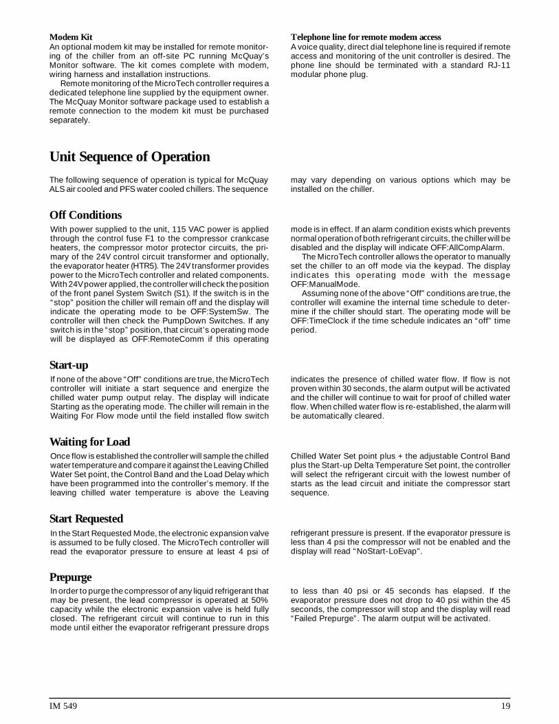
Modem KitAn optional modem kit may be installed for remote monitor-ing of the chiller from an off-site PC running McQuay’sMonitor software. The kit comes complete with modem,wiring harness and installation instructions.
Remote monitoring of the MicroTech controller requires adedicated telephone line supplied by the equipment owner.The McQuay Monitor software package used to establish aremote connection to the modem kit must be purchasedseparately.
Telephone line for remote modem accessA voice quality, direct dial telephone line is required if remoteaccess and monitoring of the unit controller is desired. Thephone line should be terminated with a standard RJ-11modular phone plug.
Unit Sequence of Operation
The following sequence of operation is typical for McQuayALS air cooled and PFS water cooled chillers. The sequence
may vary depending on various options which may beinstalled on the chiller.
Off ConditionsWith power supplied to the unit, 115 VAC power is appliedthrough the control fuse F1 to the compressor crankcaseheaters, the compressor motor protector circuits, the pri-mary of the 24V control circuit transformer and optionally,the evaporator heater (HTR5). The 24V transformer providespower to the MicroTech controller and related components.With 24V power applied, the controller will check the positionof the front panel System Switch (S1). If the switch is in the“stop” position the chiller will remain off and the display willindicate the operating mode to be OFF:SystemSw. Thecontroller will then check the PumpDown Switches. If anyswitch is in the “stop” position, that circuit’s operating modewill be displayed as OFF:RemoteComm if this operating
mode is in effect. If an alarm condition exists which preventsnormal operation of both refrigerant circuits, the chiller will bedisabled and the display will indicate OFF:AllCompAlarm.
The MicroTech controller allows the operator to manuallyset the chiller to an off mode via the keypad. The displayindicates this operating mode with the messageOFF:ManualMode.
Assuming none of the above “Off” conditions are true, thecontroller will examine the internal time schedule to deter-mine if the chiller should start. The operating mode will beOFF:TimeClock if the time schedule indicates an “off” timeperiod.
Start-upIf none of the above “Off” conditions are true, the MicroTechcontroller will initiate a start sequence and energize thechilled water pump output relay. The display will indicateStarting as the operating mode. The chiller will remain in theWaiting For Flow mode until the field installed flow switch
indicates the presence of chilled water flow. If flow is notproven within 30 seconds, the alarm output will be activatedand the chiller will continue to wait for proof of chilled waterflow. When chilled water flow is re-established, the alarm willbe automatically cleared.
Waiting for LoadOnce flow is established the controller will sample the chilledwater temperature and compare it against the Leaving ChilledWater Set point, the Control Band and the Load Delay whichhave been programmed into the controller’s memory. If theleaving chilled water temperature is above the Leaving
Chilled Water Set point plus + the adjustable Control Bandplus the Start-up Delta Temperature Set point, the controllerwill select the refrigerant circuit with the lowest number ofstarts as the lead circuit and initiate the compressor startsequence.
Start RequestedIn the Start Requested Mode, the electronic expansion valveis assumed to be fully closed. The MicroTech controller willread the evaporator pressure to ensure at least 4 psi of
refrigerant pressure is present. If the evaporator pressure isless than 4 psi the compressor will not be enabled and thedisplay will read “NoStart-LoEvap”.
PrepurgeIn order to purge the compressor of any liquid refrigerant thatmay be present, the lead compressor is operated at 50%capacity while the electronic expansion valve is held fullyclosed. The refrigerant circuit will continue to run in thismode until either the evaporator refrigerant pressure drops
to less than 40 psi or 45 seconds has elapsed. If theevaporator pressure does not drop to 40 psi within the 45seconds, the compressor will stop and the display will read“Failed Prepurge”. The alarm output will be activated.

20 IM 549
Opened EXVWith the evaporator pressure less than 40 psi and thecompressor still running, the electronic expansion valve willbe driven open to 200 steps. If the evaporator pressure risesabove the freeze stat set point, the chiller will advance to
Cool Staging Mode. If the circuit is in Cool Staging Mode andafter 20 seconds, the evaporator pressure remains below thefreeze state set point but is greater than 2 psi, the controllerwill transition to Low Ambient Start Mode.
Low Ambient StartIf the difference between the freeze stat set point and theevaporator refrigerant pressure is greater than 12 psi, the lowambient start timer will be set to 180 seconds. The compres-sor will continue to run for 180 seconds from the moment theexpansion valve is opened in an attempt to build up theevaporator pressure. If the difference between the freezestat set point and the evaporator refrigerant pressure isgreater than 12 psi, the following calculation will be used toset the low ambient start timer:
Low Ambient Timer = 360 - (Pressure Difference x 15)
If the calculated low ambient timer value is greater than360, the compressor will be stopped, the alarm output willbe activated and the display will indicate“FailLowAmbStart”.
Cool StageCircuit capacity at initial start will be 50%. Once the chillerhas started, the MicroTech controller will add or subtractcooling capacity to maintain the chilled water set point. Thecurrent cooling stage will be displayed on the keypad/display.
Automatic chiller staging may be overridden by selecting“Manual Cooling” as the operating mode and then choosingthe desired cooling stage.
Compressor Control
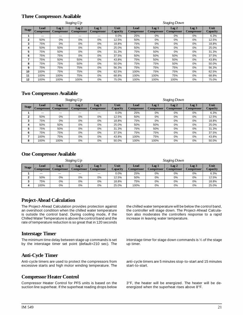
Normal Compressor Staging LogicThe Compressor Staging Logic uses an adjustable controlband and interstage timers to determine the correct numberof cooling stages to activate. A project-ahead temperature
calculation provides stable operation. The total number ofcooling stages for each circuit is dependent upon the “num-ber of cooling stages” set point.
Stage Lead Lag 1 Lag 2 Lag 3 Unit Lead Lag 1 Lag 2 Lag 3 UnitCompressor Compressor Compressor Compressor Capacity Compressor Compressor Compressor Compressor Capacity
1 — — — — 0.0% 25% 0% 0% 0% 6.3%2 50% 0% 0% 0% 12.5% 50% 0% 0% 0% 12.5%3 75% 0% 0% 0% 18.8% 75% 0% 0% 0% 18.8%4 50% 50% 0% 0% 25.0% 50% 50% 0% 0% 25.0%5 75% 50% 0% 0% 31.3% 75% 50% 0% 0% 31.3%6 75% 75% 0% 0% 37.5% 50% 50% 50% 0% 37.5%7 75% 50% 50% 0% 43.8% 75% 50% 50% 0% 43.8%8 75% 75% 50% 0% 50.0% 50% 50% 50% 50% 50.0%9 75% 75% 75% 0% 56.3% 75% 50% 50% 50% 56.3%
10 75% 75% 50% 50% 62.5% 75% 75% 50% 50% 62.5%11 75% 75% 75% 50% 68.8% 75% 75% 75% 50% 68.8%12 75% 75% 75% 75% 75.0% 75% 75% 75% 75% 75.0%13 100% 75% 75% 75% 81.3% 100% 75% 75% 75% 81.3%14 100% 100% 75% 75% 87.5% 100% 100% 75% 75% 87.5%15 100% 100% 100% 75% 93.8% 100% 100% 100% 75% 93.8%16 100% 100% 100% 100% 100.0% 100% 100% 100% 100% 100.0%
Staging Up Staging Down
Compressor Staging Sequence
Four Compressors Available
IM 549 21
Stage Lead Lag 1 Lag 2 Lag 3 Unit Lead Lag 1 Lag 2 Lag 3 UnitCompressor Compressor Compressor Compressor Capacity Compressor Compressor Compressor Compressor Capacity
1 — — — — 0.0% 25% 0% 0% 0% 6.3%2 50% 0% 0% 0% 12.5% 50% 0% 0% 0% 12.5%3 75% 0% 0% 0% 18.8% 75% 0% 0% 0% 18.8%4 50% 50% 0% 0% 25.0% 50% 50% 0% 0% 25.0%5 75% 50% 0% 0% 31.3% 75% 50% 0% 0% 31.3%6 75% 75% 0% 0% 37.5% 50% 50% 50% 0% 37.5%7 75% 50% 50% 0% 43.8% 75% 50% 50% 0% 43.8%8 75% 75% 50% 0% 50.0% 75% 75% 50% 0% 50.0%9 75% 75% 75% 0% 56.3% 75% 75% 75% 0% 56.3%
10 100% 75% 75% 0% 62.5% 100% 75% 75% 0% 62.5%11 100% 100% 75% 0% 68.8% 100% 100% 75% 0% 68.8%12 100% 100% 100% 0% 75.0% 100% 100% 100% 0% 75.0%
Staging Up Staging Down
Three Compressors Available
Stage Lead Lag 1 Lag 2 Lag 3 Unit Lead Lag 1 Lag 2 Lag 3 UnitCompressor Compressor Compressor Compressor Capacity Compressor Compressor Compressor Compressor Capacity
1 — — — — 0.0% 25% 0% 0% 0% 6.3%2 50% 0% 0% 0% 12.5% 50% 0% 0% 0% 12.5%3 75% 0% 0% 0% 18.8% 75% 0% 0% 0% 18.8%4 50% 50% 0% 0% 25.0% 50% 50% 0% 0% 25.0%5 75% 50% 0% 0% 31.3% 75% 50% 0% 0% 31.3%6 75% 75% 0% 0% 37.5% 75% 75% 0% 0% 37.5%7 100% 75% 0% 0% 43.8% 100% 75% 0% 0% 43.8%8 100% 100% 0% 0% 50.0% 100% 100% 0% 0% 50.0%
Staging Up Staging Down
Two Compressors Available
Stage Lead Lag 1 Lag 2 Lag 3 Unit Lead Lag 1 Lag 2 Lag 3 UnitCompressor Compressor Compressor Compressor Capacity Compressor Compressor Compressor Compressor Capacity
1 — — — — 0.0% 25% 0% 0% 0% 6.3%2 50% 0% 0% 0% 12.5% 50% 0% 0% 0% 12.5%3 75% 0% 0% 0% 18.8% 75% 0% 0% 0% 18.8%4 100% 0% 0% 0% 25.0% 100% 0% 0% 0% 25.0%
Staging Up Staging Down
One Compressor Available
Project-Ahead CalculationThe Project-Ahead Calculation provides protection againstan overshoot condition when the chilled water temperatureis outside the control band. During cooling mode, if theChilled Water Temperature is above the control band and therate of temperature reduction is so great that in 120 seconds
the chilled water temperature will be below the control band,the controller will stage down. The Project-Ahead Calcula-tion also moderates the controllers response to a rapidincrease in leaving water temperature.
Interstage TimerThe minimum time delay between stage up commands is setby the interstage timer set point (default=210 sec). The
interstage timer for stage down commands is 1⁄3 of the stageup timer.
Anti-Cycle TimerAnti-cycle timers are used to protect the compressors fromexcessive starts and high motor winding temperature. The
anti-cycle timers are 5 minutes stop-to-start and 15 minutesstart-to-start.
Compressor Heater ControlCompressor Heater Control for PFS units is based on thesuction line superheat. If the superheat reading drops below
3°F, the heater will be energized. The heater will be de-energized when the superheat rises above 8°F.

22 IM 549
Lead-Lag of Refrigerant Circuits
The following compressor control rules are enforced in thecontrol software. The MicroTech controller will never turn on the lag com-
pressor until the lead compressor is at 75% capacity orgreater and additional cooling capacity is required.
The MicroTech controller will not turn off the lag compres-sor until the lead compressor is running at 50% capacity,the lag compressor is running at 25% capacity and areduction in cooling capacity is required.
Automatic Lead-LagThe controller provides automatic lead-lag of refrigerationcircuits based on compressor operating hours and the num-ber of starts. The circuit with the fewest number of starts will
be started first. If circuits are operating and a stage down isrequired, the circuit with the most operating hours will cycleoff first.
Manual Lead-LagThe operator may override automatic circuit selection bymanually selecting the lead circuit via the keypad.
When the set point equals “auto”, the lead compressor isselected by the MicroTech controller based upon which
circuit has the least operating hours. Regardless of the modeselected, if the lead circuit cannot operate due to an alarmcondition or if off on cycle timers, the controller will switch tothe lag circuit.
OverviewMcQuay screw compressor chillers are supplied with SporlanSE-series electronic expansion valves. The MicroTech con-troller generates valve positioning signals to maintain refrig-erant circuit superheat to within 1.5°F of the superheat setpoint. Valve positioning signals are converted to actuator
step pulses by the EXV board which in turn drive the valve’s3-phase DC stepper motor open or closed as required. Acontrol range of 0 steps (full closed) to 760 steps (full open)is available to provide precise control of the valve position.
EXV Superheat ControlThe electronic expansion valve position will be adjusted tomaintain the refrigerant circuit’s superheat set point. Super-heat set points are based on refrigerant circuit capacity. Forcircuit capacity of 25% to 50%, the superheat set point willbe 8.0°F. For circuit capacity of 75% to 100%, the superheatset point will be 10.0°F.
When the chiller control panel is powered up, the expan-sion valve will be driven closed 800 steps. This ensures thatthe valve is fully closed prior to a call for cooling. When allrefrigerant circuit safeties are satisfied, the controller willinitiate a start sequence. When the start sequence reaches“open solenoid”, the expansion valve will be driven open tothe First Open set point (default=200 steps). The current
suction line temperature is compared against the SuctionLine Temperature set point (evaporator temp plus superheatspt) to calculate superheat error (Err). The current suction linetemperature is also compared with the previous reading tocalculate delta superheat error (DErr). These two error valuesare used to determine the magnitude and direction of theexpansion valve positioning signal. A new valve positioningsignal is calculated every 10 seconds, however, the intervalat which these signals are issued to the EXV board isdependent on the magnitude of the required positionalchange. If no change is required, the interval will be 60seconds.
Electronic Expansion Valve
Forced EXV Position ChangeWith an increase in circuit capacity, the electronic expansionvalve position will be opened by a fixed percentage of itscurrent position. This change will not occur if the superheatis less than 4°F below the superheat set point.
With a decrease in circuit capacity, the electronic expansionvalve position will be closed by a fixed percentage of itscurrent position.
When Staging DownFrom To Close100% 75% 18%75% 50% 40%50% 25% 60%
Table 8a.Table 8b.
When Staging UpFrom To Open25% 50% 65%50% 75% 50%75% 100% 25%

IM 549 23
EXV Evaporator Pressure ControlThe electronic expansion valve control will maintain a con-stant superheat for suction line temperature up to 60°F. Forsuction line temperatures greater than 61°F, the expansionvalve control logic will maintain a constant evaporator tem-perature to avoid overloading the compressor motor. The
control point will be the Evap Temp set point (default=50°F)and the control method will be the standard MicroTech Stepand Wait algorithm. When the suction line temperature dropsbelow 57°F, the MicroTech logic will resume normal super-heat control.
Chilled Water Reset Options
The controller resets the chilled water set point based on anexternal 4 to 20mA signal. At 4 mA or less, no reset will occur.At 20mA, the chilled water set point will be reset by an
amount equal to the value stored in the Maximum Reset setpoint. The reset schedule is linear and may be calculated usingFigure 12.
Figure 12.
Chilled Water Reset (Remote 4-20mA)
The MicroTech controller has dual chilled water set pointswhen ice mode is selected. With an external reset signal of4mA or less, the chilled water reset will be zero. If the externalreset signal is greater than 4mA, maximum reset will be in
Ice Mode
Table 9.
effect. For installations requiring operation in ice mode, thefollowing set points should be adjusted to accommodate thereduced system temperature and pressures.
The reset mode can be set to “network” if chilled water resetvia communications network is desired. The chiller controller
Network Resetreceives a signal from the network master panel in the rangeof 0% to 100% of maximum reset.
Per
cent
of
max
imum
res
et
100
80
60
40
20
00 1 2 3 4 5 6 7 8 9 10 11 12 13 14 15 16 17 18 19 20
External 0-10mA signal
Set Point Monitors Default Ice Mode
A pressure value equivalentFreezeStat Low Evap Pressure 54 psig to the leaving solution
temperature minus 10°F
A temperature value equalFreezeH20 Leaving Solution 36°F to the leaving solution
temperature minus 4°F
A pressure valve equal toStpPumpDn Final Pumpdown 34 psig the FreezeStat set point
minus 10 psi
24 IM 549
When return water is selected as the reset mode, theMicroTech controller will adjust the leaving chilled water setpoint to maintain a constant return water temperature equalto the return water set point. The return water temperature issampled every 5 minutes and a proportional correction is
Return Water Resetmade to the leaving chilled water set point. The correctedleaving water set point is never set to a value greater than thereturn water set point and is never set to a value less than theactual leaving chilled water set point.
The controller will limit the total number of stages based onan external 4 to 20mA signal regardless of the amount ofcooling actually required. A 4mA or less signal will enable all
Remote Demand Limitstages while a 20mA signal will allow only 1 stage to operate.The effect of the reset signal may be calculated by usingFigure 13.
Unit demand limit via network communication may be se-lected if desired. The chiller controller receives a demand
Network Demand Limitlimit signal from the network master panel in the range of 0%to 100% with 0 equaling no limit.
The soft loading feature limits the number of cooling stageswhich may be energized by the controller to prevent unnec-essary electrical demand and possible over-shoot of thedesired leaving chilled water temperature. Soft loading istypically used during morning start-up. When the controller
Soft Loadingenters the “Cool Staging” mode of operation, the controllerwill start a count down timer to indicate how long the unit hasbeen in the cool staging mode. The maximum number ofcooling stages will be limited to the soft load set point untilthe soft load count down timer equals zero.
The controller can limit the rate at which the chilled waterloop temperature is reduced. Whenever the rate of tempera-
Max Pull Downture decrease exceeds the maximum pull down set point, noadditional cooling stages will be activated.
Condenser Fan Control
The first condenser fan staging will be started in conjunctionwith the first compressor to provide initial head pressurecontrol. The MicroTech controller continuously monitors thelift pressure referenced to several head pressure control setpoints and will adjust the number of operating condenser
Condenser Fan Stagingfans as required to maintain proper head pressure.
For PFS water cooled units, the condenser pump will bestarted in conjunction with the first compressor to providehead pressure control.
For each circuit, the first stage of condenser fans will bewired in parallel with the compressor output so that they areenergized with the compressor. For chillers with optionalSpeedTrol, the first condenser fan stage will receive a controlsignal from the AOX board which in turn modulates theJohnson Controls S66DC-1 to provide variable speed fanoperation. Each circuit has 3 additional digital outputs avail-able for refrigerant head pressure control. Each output willenergize an additional bank of condenser fans with eachbank consisting of 1 or 2 fans depending on the size of theunit. Each output energizes additional heat rejection due toincreased air flow across the air cooled condenser regard-
Head Pressure Control (Air Cooled Units Only)less of the number of fans. If the outdoor ambient tempera-ture is greater than 60°F when the unit is started, oneadditional condenser fan stage will be energized. If theoutdoor ambient temperature is greater than 80°F, twoadditional fan stages will be energized.
ALS unit EERs are maximized by not allowing the lastcondenser fan stage to operate when the unit capacity is25% and the condenser pressure is below 200 psi. The lastfan stage will operate if the condenser pressure is above 220psi at 25% unit capacity.
IM 549 25
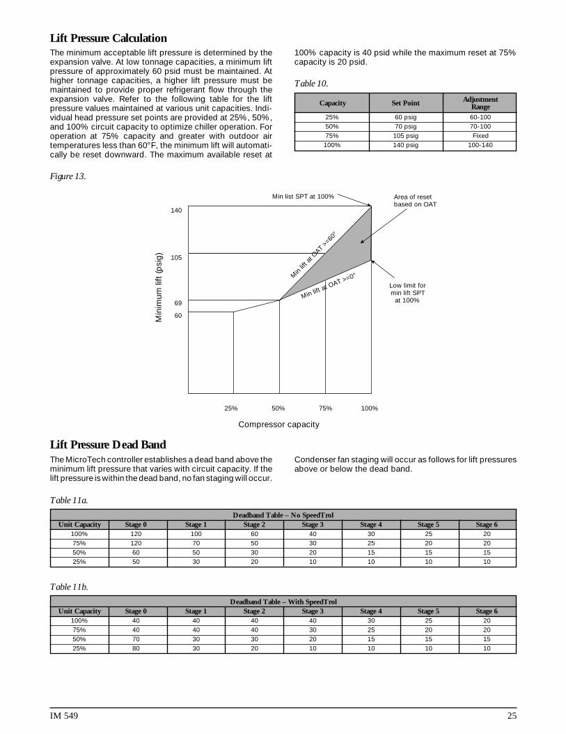
The minimum acceptable lift pressure is determined by theexpansion valve. At low tonnage capacities, a minimum liftpressure of approximately 60 psid must be maintained. Athigher tonnage capacities, a higher lift pressure must bemaintained to provide proper refrigerant flow through theexpansion valve. Refer to the following table for the liftpressure values maintained at various unit capacities. Indi-vidual head pressure set points are provided at 25%, 50%,and 100% circuit capacity to optimize chiller operation. Foroperation at 75% capacity and greater with outdoor airtemperatures less than 60°F, the minimum lift will automati-cally be reset downward. The maximum available reset at
Lift Pressure Calculation
Table 10.
100% capacity is 40 psid while the maximum reset at 75%capacity is 20 psid.
Figure 13.
Min list SPT at 100% Area of resetbased on OAT
Low limit formin lift SPT
at 100%
Min
imum
lift
(psi
g)
140
105
60
69
Min
lift a
t OAT
>=60°
Min lift at OAT >=0°
Compressor capacity
25% 50% 75% 100%
The MicroTech controller establishes a dead band above theminimum lift pressure that varies with circuit capacity. If thelift pressure is within the dead band, no fan staging will occur.
Lift Pressure Dead BandCondenser fan staging will occur as follows for lift pressuresabove or below the dead band.
Table 11a.
Table 11b.
Capacity Set Point AdjustmentRange
25% 60 psig 60-10050% 70 psig 70-10075% 105 psig Fixed
100% 140 psig 100-140
Deadband Table – With SpeedTrolUnit Capacity Stage 0 Stage 1 Stage 2 Stage 3 Stage 4 Stage 5 Stage 6
100% 40 40 40 40 30 25 2075% 40 40 40 30 25 20 2050% 70 30 30 20 15 15 1525% 80 30 20 10 10 10 10
Deadband Table – No SpeedTrolUnit Capacity Stage 0 Stage 1 Stage 2 Stage 3 Stage 4 Stage 5 Stage 6
100% 120 100 60 40 30 25 2075% 120 70 50 30 25 20 2050% 60 50 30 20 15 15 1525% 50 30 20 10 10 10 10
26 IM 549
Every four seconds, the controller records the differencebetween the maximum condenser pressure (as defined bythe minimum lift plus the dead band) and the actual con-denser refrigerant pressure. This value is added to thepreviously recorded values and when the accumulated total
Condenser Fan Stage Upis equal to or greater than the stage up set point, thecontroller starts an additional fan stage. The accumulatedtotal is set to zero whenever a fan stage change occurs or thecondenser pressure falls inside the dead band. Fan stages 5or 6 will not be enabled unless the circuit capacity is greaterthan 50%.
The controller logic will bring on multiple condenser fan
High Pressure Stage Upstages if a rapid rise in pressure is detected.
Every four seconds, the controller records the differencebetween the minimum condenser pressure and the actualcondenser refrigerant pressure. This value is added to thepreviously recorded values and when the accumulated totalis equal to or greater than the stage down set point, the
Condenser Fan Stage Downcontroller decrements a fan stage. The accumulated total isset to zero whenever a fan stage change occurs or thecondenser pressure rises inside the dead band. Fan stages5 or 6 will automatically be disabled whenever the circuitcapacity falls to 50% or less.
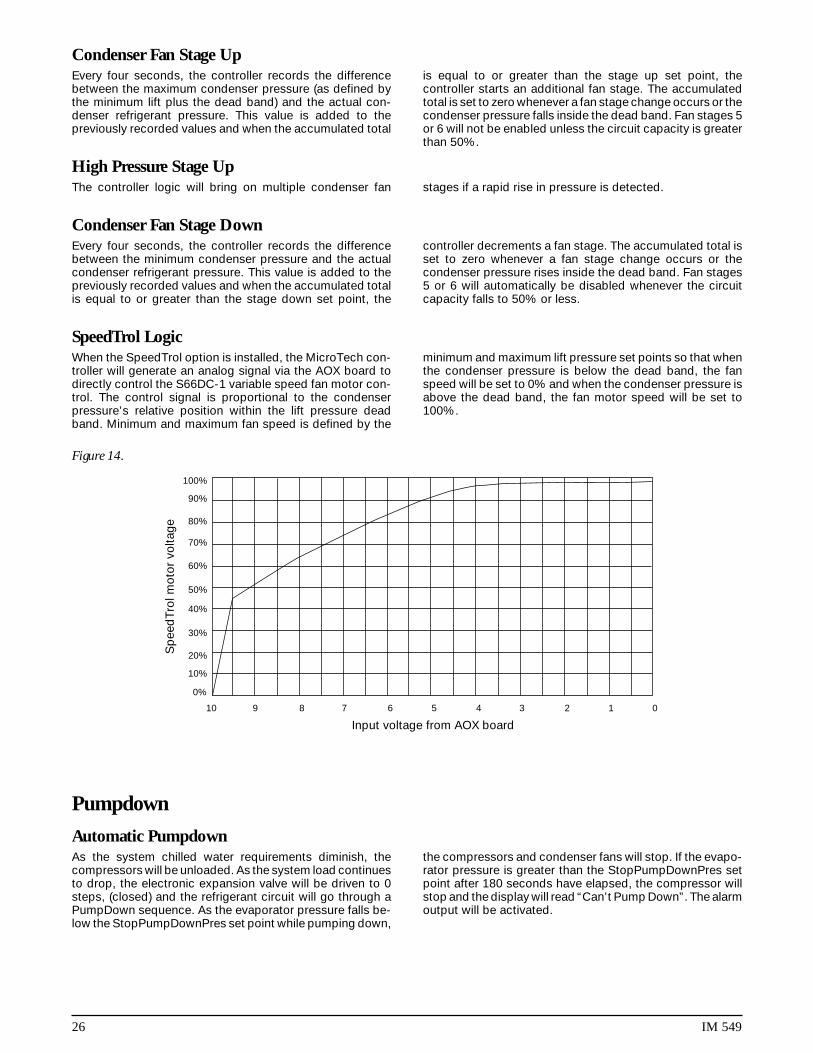
When the SpeedTrol option is installed, the MicroTech con-troller will generate an analog signal via the AOX board todirectly control the S66DC-1 variable speed fan motor con-trol. The control signal is proportional to the condenserpressure’s relative position within the lift pressure deadband. Minimum and maximum fan speed is defined by the
SpeedTrol Logicminimum and maximum lift pressure set points so that whenthe condenser pressure is below the dead band, the fanspeed will be set to 0% and when the condenser pressure isabove the dead band, the fan motor speed will be set to100%.
Figure 14.
100%
90%
80%
70%
60%
50%
40%
30%
20%
10%
0%
Sp
eed
Trol
mot
or v
olta
ge
Input voltage from AOX board
10 9 8 7 6 5 4 3 2 1 0
Pumpdown
As the system chilled water requirements diminish, thecompressors will be unloaded. As the system load continuesto drop, the electronic expansion valve will be driven to 0steps, (closed) and the refrigerant circuit will go through aPumpDown sequence. As the evaporator pressure falls be-low the StopPumpDownPres set point while pumping down,
Automatic Pumpdownthe compressors and condenser fans will stop. If the evapo-rator pressure is greater than the StopPumpDownPres setpoint after 180 seconds have elapsed, the compressor willstop and the display will read “Can’t Pump Down”. The alarmoutput will be activated.

IM 549 27
When the compressor is running and the circuit pumpdownswitch is moved from the Auto position to the Stop position,the circuit will pumpdown and stop when the evaporatorpressure falls below the “StopPumpdownPressure” set point.
When the compressor is not running and the circuitpumpdown switch is moved from the Auto position to theStop position, the controller will initiate a pumpdown only ifthe evaporator pressure is above the “Begin PumpdownPressure” set point. The compressor will stop when the
Manual Pumpdownevaporator pressure falls below the “Stop Pumpdown Pres-sure” set point.
An additional pumpdown sequence can be performed bymoving the pumpdown switch to the Auto position for ap-proximately 3 seconds and then back to the Stop position. Ifthe evaporator pressure is above the “Begin PumpdownPressure” set point, the controller will initiate a pumpdownsequence and the compressor will stop when the evaporatorpressure falls below the “StopPumpdownPressure” set point.
The normal pumpdown sequence will stop when the evapo-rator pressure equals the Stop Pumpdown set point pres-sure. A control set point called FullPumpDown has beenprovided which will allow an extended pumpdown for servicepurposes.
The default value for the FullPumpDown set point is “No”.By changing this setting to “Yes”, the circuit will attempt topump down to 2 psi during the next pumpdown cycle. If 2 psi
Service Pumpdowncannot be obtained, the compressor will stop after 300seconds have elapsed. The set point will be set to “No”automatically at the end of the cycle.
Note: All pumpdown modes are disabled if the systemswitch (S1) is in the Stop position.
Note: Compressor capacity during a pumpdown sequencewill be 50%.
Safety Systems
Alarm conditions which are common to both refrigerantcircuits are considered to be system alarms. On a systemalarm, the MicroTech controller will shut down both com-pressors and energize the alarm output.
Loss of Chw flowOn a loss of chilled water flow for three consecutive secondswhile the chiller is in cooling mode, all operating refrigerantcircuits will pump down and stop. The display will read “Lossof ChW Flow”. When chilled water flow resumes, the chillerwill initiate a normal start sequence.
Bad phase/voltageThe factory mounted voltage protection device will signal theMicroTech controller if the incoming 3-phase power is notwithin acceptable limits. The controller will immediately shutthe chiller down. When the voltage protection device indi-
System Alarmscates that the incoming power is back within acceptablelimits, normal chiller operation will resume.
No 5VDC @AI#5The controller continuously monitors the output of bothinternal 5VDC power supplies and calculates their ratio. If themicroprocessor is not receiving an acceptable volts ratiosignal, the unit will be shut down. The voltage present atanalog input #5 must be between 4.15 and 4.94 VDC.
Chilled water freeze protectIf the leaving chilled water temperature falls below theadjustable freeze H2O set point, the unit will be shut down.
Bad leaving chilled water sensorIf the MicroTech controller detects an open or shortedleaving water sensor, the chiller will be shut down.
Alarm conditions which are unique to each refrigerant circuitare considered to be circuit alarms. On a circuit alarm, theMicroTech controller will shut down the affected circuit’scompressor and energize the alarm output.
Mechanical high pressureClosure of the HP1 or HP2 relay contacts indicates anabnormally high compressor discharge pressure. The latch-ing mechanical high pressure switch must be reset beforethe MicroTech alarm can be cleared.
The mechanical high pressure switches should be set totrip at the following pressures.
ALS Units . . . 400 psiPFS Units . . . 380 psi
Circuit AlarmsHigh condenser pressureIf the condenser pressure as sensed by the pressure trans-ducer exceeds the high condenser pressure set point (de-fault=380 psi), the circuit will be shut down until the alarm ismanually reset.
High condenser pressure stage downIf the condenser pressure rises to within 20 psi of thecondenser high pressure set point, the controller will auto-matically reduce the refrigerant circuit’s capacity by onecooling stage every 10 seconds until the condenser pressurefalls below the 20 psi threshold. (HiCondPre-20)
If two high pressure stage downs occur within a 60 minuteperiod, the normal interstage timer will be extended to 15minutes to inhibit any stage up requests. Normal chillerstaging will resume once this 15 minute timer expires.

28 IM 549
High condenser pressure stage holdIf the condenser pressure rises to within 30 psi of thecondenser high pressure set point, the controller will hold thecircuit at its current capacity.
Normal chiller operation will resume once the condenserpressure drops below the high pressure stage hold threshold.
No liquid startIf liquid refrigerant is not present at the compressor’s injec-tion port within 20 seconds of a start request, the circuit willbe shut down and the fault will be recorded. The circuit willautomatically attempt to re-start after the cycle timer ex-pires. If a no liquid start is recorded during the second startattempt, the circuit is shut down and the alarm output isenergized. No additional starts will be attempted until thealarm is manually cleared.
No liquid runThe refrigerant circuit will be shut down if liquid injection islost during normal chiller operation. One automatic re-startwill occur after the cycle timer expires. If another no liquid runfault is recorded after the re-start, the circuit will be shutdown and the alarm output will be energized.
Can’t start-low evaporator pressureIf the evaporator pressure is less than 4 psi when a compres-sor start is requested, the start will be aborted.
Low evaporator pressureA low evaporator pressure alarm will occur if the refrigerantpressure drops below the low pressure cutout set point(default=2 psi).
Freeze protect stage down and freeze stat protectThe controller records the amount of time the evaporatorrefrigerant pressure is below the freeze stat set point (de-fault=54 psi). The magnitude of the error will determine thetime delay before a circuit stage down or alarm shutdownoccurs.
Error S.D. Delay Alarm Delay2 psi 100 seconds 160*4 psi 87 seconds 1406 psi 74 seconds 1008 psi 60 seconds 100
10 psi 48 seconds 8012 psi 35 seconds 4014 psi 22 seconds 4017 psi 0 seconds 0
Table 12.
Once the time delay is satisfied, the controller will stagedown once every 20 seconds. If the controller stages downto cooling stage 0, the circuit will pump down and thecompressor will stop. The circuit will restart automaticallywhen the anti cycle timer expires.
Failed pre-purgeThe start sequence will be aborted if the compressor cannotpre-purge the evaporator.
Failed EXV or low refrigerant chargeIf the pre-purge is successful but the evaporator pressuredoes not rise after the electronic expansion valve is com-manded to open, the circuit will be shut down.
Failed low ambient startThe circuit will be shut down if the controller records anunsuccessful low ambient start.
Can’t pump downA pumpdown elapse timer (180 seconds) is started wheneverthe controller initiates a pumpdown sequence. If the circuit isstill attempting to pump down when the timer expires, thecompressor is stopped and the alarm output is activated.The display reads “Can’t Pump Down”.
Bad evaporator pressure sensorA shorted or open evaporator pressure sensor will shut downthe refrigerant circuit and activate the alarm output.
Bad condenser pressure sensorA shorted or open condenser pressure sensor will shut downthe refrigerant circuit and activate the alarm output.
Wait floodedSuction superheat is less than 3°F and compressor will notstart.
Wail flooded xxxLiquid presence sensor detected liquid in the compressor.xxx indicates time in minutes before unit will start after liquidclears from the compressor.
IM 549 29
CAUTIONService test mode should only be used byMcQuayService personnel or other factory trained tech-nicians. The following test procedures will disable allnormal chiller controls and safeties. All compressorsMUST be disabled by opening circuit breakers or bydisconnecting the 3-phase power before beginningtests. Failure to do so can result in severe compressordamage.
!
MicroTech Controller Test Procedures
Select control mode, menu 13 and set the chiller’s controlmode to Service Testing. Select menu 22 and with the Prevor Next item keys, select the digital output you wish to test.Enter the service password when prompted by the display.Pressing the Inc key will turn the selected output on, pressingthe Decr key will turn it off. All outputs except 1, 2, 4 and 8 willremain in their last commanded state until the Service Testing
Service Test (Digital Outputs)
Keypad/Display
OverviewThe information stored in the MicroTech controller can beaccessed through the keypad using a tree-like structure.This tree structure is divided into Categories, Menus andMenu Items. There are three categories which make up the
tree structure: STATUS, CONTROL, and ALARM. Each cat-egory is divided into Menus and each menu into Menu Items.The three categories are described below.
Status CategoryMenus and menu items in this category provide informationon the MicroTech operating conditions and the chiller oper-ating conditions. The entries under each menu item in this
category provide information only and are not changeablethrough the MicroTech keypad.
Control CategoryMenus and menu items in this category provide for the inputof all the unit control parameters.
These include cooling control, compressor control and
condenser fan control parameters as well as time schedulesand alarm limits. The entries under these menu items arechangeable through the MicroTech keypad.
mode is turned off. Manually operating outputs 1 and 2 willdrive the electronic expansion valve open or closed. Com-pressor MCR outputs 4 and 8 will only remain in the on statefor 15 seconds.
Exit the Service Testing mode by selecting the desiredchiller operating mode from menu 13.
Service test (Digital Inputs)Select control mode, menu 13 and set the chiller’s controlmode to Service Testing. Select menu 22 and with the Prevor Next item keys, select test #16, DH1. The current state ofthe first 8 digital inputs (0-7) will be represented on thekeypad/display as a row of ones or zeroes where 1 equals“on” and 0 equals “off”. By manipulating field wired devices(system switch, motor project, etc.) and watching the key-pad/display, the status of the first eight digital inputs can beverified.
Press the Next item key to select test #17, DH2. Thecurrent state of the second 8 digital inputs (8-15) will berepresented on the keypad/display as a row of ones or zeroswhere 1 equals “on” and 0 equals “off”. By manipulating fieldwired devices (flow switch, remote stop switch, etc.) andwatching the keypad/display, the status of the second eightdigital inputs can be verified.
Exit the Service Testing mode by selecting the desiredchiller operating mode from menu 13.

30 IM 549
Alarm CategoryMenus and menu items in this category provide information regarding current and previous alarm conditions.
Display FormatThe information stored in the MicroTech controller treestructure can be viewed (one menu and menu character LCDdisplay. The current MENU is shown on the top line and thecurrent MENU ITEM is shown on the bottom line of thedisplay. The operator can select either English or metricengineering units. Once the desired engineering units havebeen selected, momentarily remove and restore power to theMicroTech controller to complete the change.
English Units:Temperature = °F (Fahrenheit)Pressure = Psi (Pound per sq. inch)
PsigPsid
Metric Units:Temperature = °C (Centigrade)Pressure = Kpa (Kilo Pascals)
KpagKpda
MicroTech Component Test Procedures & ALS Units
Status LED diagnosticsThe MCB status LED indications can aid in controller diag-nostics. If the status LEDs do not operate normally asdescribed in the “Component Data” section of this handout(see Tables 1 & 2), there is a problem with the MCB. Followingare troubleshooting procedures for the various symptoms.
Red LED remains onIf the red LED remains on after the 5-second self-test period,
it is likely that the MCB is defective. However, this can alsooccur in some instances if there is a power supply problem.Refer to “Troubleshooting Power Problems” below.
Red and green LEDs offIf the red and green LEDs do not turn on after power is appliedto the controller, there is likely a defective component or aproblem in the controller’s power distribution circuits. Referto “Troubleshooting Power Problems” below.
The MCB status receives 18 Vac, center-tapped power froma transformer. It then distributes both 5 Vdc and 13 Vdcpower to various MicroTech components. A problem thatexists in any of these components can affect the MCB andthus the entire control system. Power problems can becaused by an external short, which can blow a fuse, or adefective component, which can either blow a fuse or createan excessive load on the power supply. An excessive loadcan lower the power supply voltages to unacceptable levels.Use the following procedure to isolate the problem. Note:This procedure may require two or three spare MCB fuses.
1. Verify that circuit breaker CB1 is closed.2. Remove the MCB Power In connector and check for 9
Vac between the terminals on the plug corresponding toterminals 2 and 3 on the board (Figure 2). Then check for9 Vac between the terminals on the plug correspondingto terminals 1 and 3 on the board. (Readings of 9-12 Vacare acceptable.)
If 9 Vac is present between both sets of terminals, goto step 3.
If 9 Vac is not present between both sets of terminals,check both transformers and all wiring between the 115Vac source and the Power In plug.
3. Remove power from the controller by opening circuitbreaker CB1. Check the MCB power supply input fuses(F1 and F2) with an ohmmeter. See Figure 3. A good fusewill have negligible resistance through it (less than 2ohms).
If either or both fuses are blown, replace them. Go tostep 4.
If the fuses are intact, the MCB is defective.
Troubleshooting Power Problems4. Reconnect the Power In connector and disconnect all
other connectors on the MCB. Cycle power to thecontroller (close and then open CB1) and check thepower fuses.
If both fuses are intact, go to step 5.5. If either fuse blows, the MCB is defective. Reconnect the
keypad/display ribbon cable (if equipped with keypad/display door). Cycle power to the controller and check thepower fuses.
If both fuses are intact, go to step 6.If either fuse blows, check the keypad/display and the
connecting ribbon cable for shorts. Either one may bedefective.
6. Reconnect the analog input ribbon cable. Cycle power tothe controller and check the power fuses.
If both fuses are intact, go to step 7.If either fuse blows, check the ADI board, the connect-
ing ribbon cable, and the field wiring for shorts. Any ofthese may be defective. Try repeating this step afterremoving or swapping the ADI board.
7. Reconnect the digital input ribbon cable. Cycle power tothe controller and check the power fuses.
If both fuses are intact, go to step 8.If either fuse blows, check the ADI board, the connect-
ing ribbon cable, and the field wiring for shorts. Any ofthese may be defective.
8. Reconnect the digital output ribbon cable to the MCB.Cycle power to the controller and check the power fuses.
If both fuses are intact, go to step 9.If either fuse blows, check Output Board and the
connecting ribbon cable. Either of these may be defective.
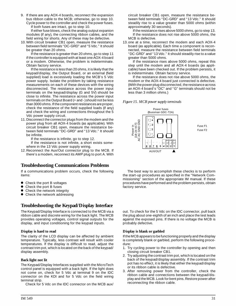
IM 549 31
9. If there are any AOX-4 boards, reconnect the expansionbus ribbon cable to the MCB; otherwise, go to step 10.Cycle power to the controller and check the power fuses.
If both fuses are intact, go to step 10.If either fuse blows, check the analog output expanion
modules (if any), the connecting ribbon cables, and thefield wiring for shorts. Any of these may be defective.
10. With circuit breaker CB1 open, measure the resistancebetween field terminals “DC-GRD” and “5 Vdc.” It shouldbe greater than 20 ohms.
If the resistance is greater than 20 ohms, go to step 11if the controller is equipped with at least one AOX-4 boardor a modem. Otherwise, the problem is indeterminate.Obtain factory service.
If the resistance is less than 20 ohms, it is likely that thekeypad/display, the Output Board, or an external (fieldsupplied) load is excessively loading the MCB’s 5 Vdcpower supply. Isolate the problem by taking resistancemeasurements on each of these devices with the wiringdisconnected. The resistance across the power inputterminals on the keypad/display (G and 5V) should beclose to infinite. The resistance across the power inputterminals on the Output Board (+ and -) should not be lessthan 3000 ohms. If the component resistances are proper,check the resistance of the field supplied loads (if any)and check the wiring and connections throughout the 5Vdc power supply circuit.
11. Disconnect the connector plugs from the modem and thepower plug from all AOX-4 boards (as applicable). Withcircuit breaker CB1 open, measure the resistance be-tween field terminals “DC-GRD” and “13 Vdc.” It shouldbe infinite.
If the resistance is infinite, go to step 12.If the resistance is not infinite, a short exists some-
where in the 13 Vdc power supply wiring.12. Reconnect the Aux/Out connector plug to the MCB. If
there’s a modem, reconnect its AMP plug to port A. With
circuit breaker CB1 open, measure the resistance be-tween field terminals “DC-GRD” and “13 Vdc.” It shouldsteadily rise to a value greater than 5000 ohms (withinapproximately 30 seconds).
If the resistance rises above 5000 ohms, go to step 13.If the resistance does not rise above 5000 ohms, the
MCB is defective.13. one at a time, reconnect the modem and each AOX-4
board (as applicable). Each time a component is recon-nected, measure the resistance between field terminals“DC-GRD” and “13 Vdc.” It should steadily rise to a valuegreater than 5000 ohms.
If the resistance rises above 5000 ohms, repeat thisstep until the modem and all AOX-4 boards (as appli-cable) have been checked out. If the problem persists, itis indeterminate. Obtain factory service.
If the resistance does not rise above 5000 ohms, themodem or the AOX-4 board just connected is defective.(With the power plug disconnected, the resistance acrossan AOX-4 board’s “DC” and “G” terminals should not beless than 3 million ohms.)
Figure 15. MCB power supply terminals
If a communications problem occurs, check the followingitems:
Check the port B voltages Check the port B fuses Check the network integrity Check the network addressing
Troubleshooting Communications ProblemsThe best way to accomplish these checks is to perform
the start-up procedures as specified in the “Network Com-missioning” section of the appropriate IM manual. If theseprocedures have performed and the problem persists, obtainfactory service.
The Keypad/Display Interface is connected to the MCB via aribbon cable and discrete wiring for the back light. The MCBprovides operating voltages, control signal outputs for thedisplay, and input conditioning for the keypad inputs.
Display is hard to readThe clarity of the LCD display can be affected by ambienttemperature. Typically, less contrast will result with coolertemperatures. If the display is difficult to read, adjust thecontrast trim pot, which is located on the back of the keypad/display assembly.
Back light not litThe Keypad/Display Interfaces supplied with the MicroTechcontrol panel is equipped with a back light. If the light doesnot come on, check for 5 Vdc at terminal 9 on the IDCconnector on the KDI and for 5 Vdc on the field wiringterminal strip.
Check for 5 Vdc on the IDC connector on the MCB aux/
Troubleshooting the Keypad/Display Interfaceout. To check for the 5 Vdc on the IDC connector, pull backthe plug about one-eighth of an inch and place the test leadsagainst the exposed pins. If there is no voltage the MCB isprobably defective.
Display is blank or garbledIf the MCB appears to be functioning properly and the displayis completely blank or garbled, perform the following proce-dure:1. Try cycling power to the controller by opening and then
closing circuit breaker CB1.2. Try adjusting the contrast trim pot, which is located on the
back of the keypad/display assembly. If the contrast trimpot has no effect, it is likely that either the keypad/displayor its ribbon cable is defective.
3. After removing power from the controller, check theribbon cable and connections between the keypad/dis-play and the MCB. Look for bent pins. Restore power afterreconnecting the ribbon cable.
Power fuses(Bussman GDC-T2A)
Fuse F2
AUX/OUT
Po
wer
in[1
8-24
VC
T]
AC
AC
GN
D G
ND
Fuse F1

32 IM 549
4. Try swapping a known good ribbon cable and keypad/display. Swap these components separately to isolate theproblem. Remove power from the controller before dis-
connecting the suspect component, and restore powerafter connecting the replacement component. If the prob-lem persists, it is likely that the MCB is defective.
An analog input, such as a temperature sensor, is connectedto the Analog Input terminal strip on the ADI board. Theanalog input is then conditioned by the ADI board. Theconditioned input is transferred to the MCB via a ribboncable.
Analog input not read by the MCBIf the MCB appears to be functioning properly and the analoginput is not being read by the MCB, perform the followingprocedure:
1. Try cycling power to the controller by opening and then
Troubleshooting Analog Inputsclosing circuit breaker CB1.
2. Check the ribbon cable, power wiring connector, and thefield wiring connections from the analog input device.Look for bent pins, cable on backwards, or miswires.Restore power after reconnecting all cables and wires.
3. If the problem persists, try swapping a known good ribboncable, an ADI board, or analog input device. Swap thesecomponents separately to isolate the problem. Removepower from the controller before disconnecting the sus-pect component, and restore power after connecting thereplacement component. If the problem persists, it islikely that the MCB is defective.
A digital input device is connected to the Digital Inputterminal strip on the Input Conditioning Module TerminalBoard. 24 Vac, supplied by the CSC, is sent to the digitalinput device via a supply wire. When a contact in the digitaldevice makes, a return signal is sent back to the Digital Inputterminal strip. The signal is then conditioned by the InputConditioning Module (ICM). The conditioned digital input isthen sent to the MCB via a ribbon cable.
Digital input not read by the MCBIf the MCB appears to be functioning properly and the digitalinput is not being read by the MCB, perform the followingprocedure:
Troubleshooting Digital Inputs1. Try cycling power to the controller by opening and then
closing circuit breaker CB1.2. Check the ribbon cable, power wiring connector, and the
field wiring connections from the digital input device.Look for bent pins, cable on backwards, or miswires.Restore power after reconnecting all cables and wires.
3. If the problem persists, try swapping a known good ribboncable, an ADI board, or a digital input device. Swap thesecomponents separately to isolate the problem. Removepower from the controller before disconnecting the sus-pect component, and restore power after connecting thereplacement component. If the problem persists, it islikely that the MCB is defective.
Variable voltage or current control signals are sent to analogoutputs by the MCB through the Analog Output ExpansionModule (AOX-4) (This can be on the ALS units as the optionalfan speed control). The MCB sends a voltage or currentsignal to the AOX-4 via a ribbon cable. Jumpers on the AOX-4 determine what type of output will be sent to the analogoutput device. The analog output signals are sent from theAOX-4 by connecting a two-pin Phoenix connector to theAnalog Output Ports on the AOX-4.
Analog output device is not operating correctlyIf the MCB appears to be functioning properly and the analogoutput device is not operating correctly, perform the follow-ing procedure:
1. Try cycling power to the controller by opening and thenclosing circuit breaker CB1.
2. Check the ribbon cable(s), power wiring from the trans-former to the AOX-4, field wiring connections from the
Troubleshooting Analog OutputsAOX-4 to the analog output device, and the power wiringfrom the external power supply to the output device. Lookfor bent pins, cable on backwards, or miswires. Restorepower after reconnecting all cables and wires.
Note: If the analog output signal supplied by the MCBis a voltage signal (0-5, 0-10 Vdc), the external powersupply ground must be grounded to the MCB chassisground.
3. If the problem persists, try swapping a known good AOX-4, ribbon cable(s), analog output device, or external powersupply. Swap these components separately to isolate theproblem. Remove power from the controller and analogoutput device before disconnecting the suspect compo-nent, and restore power after connecting the replacementcomponent. If the problem persists, it is likely that theMCB is defective.

IM 549 33
Each output on the Output Board consists of a solid-staterelay, a LED, 5-amp fuse, and an MOV (metal oxide varistor).
Normally, when the MCB commands an output to ener-gize, the solid-state relay contacts will close and the LED willglow. The contacts of each solid-state relay are in series witha 5-amp fuse. These fuses resemble small resistors and arelocated on the board adjacent to the relays they serve. Thefuses are pressed into place. They can be removed with aneedle nose pliers. The MOV, which is located on the under-side of the output board, protects the solid-state relay fromhigh transient voltages. MOVs are part of the output boardand cannot be replaced.
Following are troubleshooting procedures for varioussymptoms of output board problems.
Note: It should be possible to determine whether a solid-state relay is defective by using these procedures. However,if you need more information on troubleshooting them, referto “Troubleshooting Solid-State relays” below.
Troubleshooting Output Boards
Figure 16. Output board relay socket
WARNINGElectric shock hazard.Can cause severe injury or death.
Even when power to the panel is off, solid-state relay socketterminals 1 and 2 on the output board could be connectedto high voltage (see Figure 5). Avoid them.
!
One LED outIf one of the Output Board LEDs fails to illuminate when theMCB is commanding the associated output to energize,perform the following procedure:
1. Remove power from the controller by opening CB1. Swapthe suspect relay with a known good relay. Try to choosea relay that will not affect unit operation. Restore power byclosing CB1.
If the LED does not light, go to step 2.If the LED lights, the suspect relay is defective.
2. Remove power from the controller. Check the ribboncable and connections between the OB and the MCB.Look for bent pins.
If the cable and connections are intact, go to step 3.3. Remove the relay from the suspect socket. Install a 330-
680 ohm resistor between terminals 3 and 5 as shown in
Figure 5. Restore power by placing CB1 to the ONposition. The LED should light regardless of the controller’scommand.
If the output LED illuminates, it is likely that the MCB isdefective.
If the output LED does not illuminate, the output boardis defective.
All LEDs outIf the MCB is commanding at least two outputs to energizeand none of the Output Board LEDs are lit, perform thefollowing procedure:
1. Verify that 5 Vdc is present at the Output Board’s powerterminals.
If 5 Vdc is not present, go to step 2.If 5 Vdc is present, check the ribbon cable and connec-
tions between the output board and MCB. Look for bentpins. If the cable and connections are intact, the OutputBoard or the MCB is defective.
2. Remove power from the controller by placing CB1 to theOFF position. Disconnect at least one wire from the powerinput terminals of the Output Board. The resistance shouldnot be less than 3000 ohms.
If the resistance is greater than the acceptable value,go to step 3.
If the resistance is less than the acceptable value, theOutput Board is defective.
LED lit, output not energizedIf the LED of a suspect is lit but the load connected to it is notenergized, and everything is intact between the MCB and thecoil side of the relay, perform the following procedure toisolate the problem:
1. Verify that 24 or 120 Vac power is present at the suspectoutput’s screw terminal on the Output Board.
2. Remove power from the controller by placing CB1. Swapthe suspect relay with a known good relay. Try to choosea relay that will not affect unit operation. Restore power byclosing CB1.
If the output load energizes, the suspect relay is bad.Replace the relay.
If the output load does not energize (when LED is litagain), check the load circuit wiring and components.
Output energized, LED not litIf the LED of a suspect is not lit, but the load connected to itis energized, either the solid-state relay or the MOV is bad.The solid-state relay contacts and the MOV, which are inparallel, can both fail closed. Perform the following proce-dure to isolate the problem:
1. Remove power from the controller by opening CB1. Pullthe solid-state relay from the suspect output’s socket.
2. Restore power by closing CB1.If the output load remains energized when there is no
relay in the socket, the output’s MOV has failed and thusthe Output Board must be replaced.
If the output load de-energizes, the relay that waspulled is defective.
Contact chatterContact chatter is very rapid opening and closing of con-tacts. It is usually caused by low voltage at the electrome-chanical relay or contactor coil. If contact chatter is occurringon a relay or contactor connected to one of the Output Board
Fuse
*250V~50/60 Hz*120V~50/60 Hz
Test resistor330-680 Ohm
1
2
3
4
5

34 IM 549
solid-state relays, it is also possible that a faulty connectionexists on the power supply terminals of the Aux/Out plugconnector on the MCB and the Output Board. In very rareinstances, contact chatter can be caused by a faulty solid-state relay. Perform the following procedure to isolate theproblem:
1. Verify that the voltage at the load’s power supply and atthe solid-state relay contacts is adequate.
2. Remove power from the controller by opening CB1. Swapthe suspect relay with a known good relay. Try to choosea relay that will not affect unit operation. Restore power by
closing CB1.If the chatter does not stop, go to step 3.If the chatter stops, the suspect relay is defective.
Replace the relay.3. Remove power from the controller by opening CB1. Try to
improve the connections in the Aux/Out plug insulationdisplacement terminals by pressing down on the wireswith a small screwdriver.
4. Check all other wiring and connectors for bent pins ormiswires.
If the chatter does not stop, the electromechanicalrelay or contactor is probably defective.
Troubleshooting Solid-State Relays
As shown on the unit wiring diagrams, the solid-state relayson the Output Boards all have normally open “contacts.”Actually, these contacts do not exist as they do in electrome-chanical relay. Instead of using contacts to switch the load,the solid-state relay changes its resistance from low (closed),when it is energized, to high (open), when it is de-energized.(This high resistance is approximately 100K ohms.) Becausethe output circuit through the solid-state relay remains con-tinuous regardless of whether the relay is energized, trouble-shooting a solid-state relay with a voltmeter can be tricky.
In a typical circuit, a power source is connected across asingle relay output and a load (see Figure 17). In this circuit,a solid-state relay will behave like an electromechanicalrelay. If the relay is energized, the relay output will be hot. Ifthe relay is de-energized, voltage cannot be measured at therelay output.
The circuit shown in Figure 6 is similar to a typical circuit;
Figure 17a. Testing a typical relay circuit
If an MCB board is defective and must be replaced, theproper controller software must be loaded into the replace-ment MCB. This can be done either at the factory or at thebuilding site–if a PC equipped with appropriate Monitorsoftware is available.
The factory will download the proper controller softwareinto a replacement MCB board before it is shipped if youinclude the program code with the replacement MCB partorder. If the program code is not provided, the MCB boardwill be shipped without software.
MCB ReplacementJob-specific Monitor software includes each unit and
auxiliary controller’s program. Therefore, it is possible todownload the proper controller software to a replacementMCB at the building site if a PC equipped with that job’sMonitor software is available. In addition, if the controller’sconfiguration data was stored on the PC hard drive prior tothe MCB failure, the exact configuration data (including allkeypad programmable set points and parameters) can berestored. Refer to the user’s manual supplied with the Moni-tor software for more information.
Figure 17b. Testing a typical relay circuit with a disconnection
the difference is that there is an open set of contacts, or adisconnection between the relay output and the load. In thiscircuit, a solid-state relay will not behave like an electrome-chanical relay. If the solid-state relay is energized, the relayoutput will be hot (as expected). However, if the solid-staterelay is de-energized, the relay output will still appear to behot. This is because the relay output and the voltmeter forma continuous circuit in which the relay’s resistance, thoughhigh, is insignificant compared to the voltmeter’s resistance.
This means that nearly all the voltage is dropped acrossthe voltmeter. Therefore, the voltmeter indicates that voltageis present. If a low wattage light bulb of the appropriatevoltage is used instead of a voltmeter, the bulb’s low resis-tance will load the circuit enough to eliminate the falsevoltage indication. In this situation, an incandescent testlamp is a better tool than a voltmeter.
115 VAC
Output board
DO 13
28 27
M10
Neutral
DV
Output board
DO 13
28 27
M10
Neutral
115V

IM 549 35
Use the following three procedures to connect the chillercontrollers to the network.
Communications cable checkThe network communications cable should have been in-stalled in accordance with the instructions in the “FieldWiring” section of this manual. This procedure will verify thatthere are no shorts or stray voltages anywhere in the commu-nications trunk.
Before beginning, verify that the port B connectors aredisconnected from every controller on the trunk.
1. Verify that there is no voltage between any conductor andground.
Use a voltmeter to test for voltage at the field wiringterminal block or directly on the port B connector of thelevel-1 controller. With one lead on the control panelchassis (ground), check for voltage at the “+,” “-,” and“ground” terminals. There should be no AC or DC voltage(see the Signal and Terminal columns of Table 3). If theconductors are properly terminated, this check will testfor stray voltage throughout the trunk.
Note: If you get a 2 or 3 Vdc reading, it indicates thatone or more powered controllers are connected to thetrunk. These controllers should be located and discon-nected.
2. Verify that there are no shorts between any two conduc-tors.
Use an ohmmeter to test for shorts at field wiringterminal block or directly on the port B connector of thelevel-1 controller. For the three combinations of conduc-tor pairs, there should be infinite resistance between theconductors. If the conductors are properly terminated,this check will test for shorts throughout the trunk.
Note: If you find a resistance that is high but less thaninfinite, it indicates that one or more non-powered con-trollers are connected to the trunk. These controllersshould be located and disconnected.
3. Verify that the communications wiring is continuous overthe trunk and that the field terminations are correct. (Thisstep is optional but recommended; to do it, you mustknow the physical layout of the network’s communica-tions trunk.)
Go to the last controller on one end of the daisy-chainand place a jumper across the “+” to “ground” and “-” to“ground.”
Remove the jumper and repeat this step for the othertwo conductor pairs: “+” to “ground” and “-” to “ground.”
If there is continuity for each conductor pair, the wiringis continuous and it is likely (but not guaranteed) that theterminations are correct throughout the trunk.
If there is no continuity for one or more conductor pairs,there may be a break in the trunk or the terminations at oneor more controllers may have been mixed up.
Connecting the Communications Trunk
Port B (RS-485)Acceptable Voltage
Signal Terminal Reading
+ 4 3.0 +- 0.3 Vdc
- 3 2.0 +- 0.3 Vdc
Ground 5 0.0 +- 0.2 Vdc
Table 13. Port B voltages: AMP type connector
Network Comm. Field TerminalController
+ – Ground
CSC T11-B+ T11-B– T11-GNDReciprocating Chiller TB7-138 TB7-137 TB7-139Screw Chiller TB4-54 TB4-53 TB4-55
Table 14. Network communications field wiring terminals
Level-1 controller connectionIn order for the chillers and other level-2 controllers in anetwork to connect and communicate with the level 1 con-troller, the level 1 controller is connected first.
1. Set the network address to 00 (level 1). See “Addressingthe Controllers” above for more information.
2. Push the circuit breaker (CB1) button to power up the CSCand verify that there is power to the MCB by observing theLEDs.
3. Check the voltages of port B on field wiring terminals(TB2).
Use a DC voltmeter to test for proper voltages. With theground lead on the control panel chassis (ground), checkthe voltage at the “+,” “-,” and “ground” terminals. Referto Table 13 for the correct voltage levels.
If no voltage or improper voltage levels are found,verify that the panel is energized.
4. Plug the network communications AMP connector intoport B.
Level-2 controller connectionThis procedure will verify that proper communications havebegun for each controller as it is connected to the network.You can connect the level-2 controllers in any order; how-ever, it is better to follow the daisy-chain as you proceed.This will make troubleshooting easier if communicationsproblems occur.
As a result of the previous procedures, the networkcommunications connector should be disconnected fromthe B port at every controller on the trunk except for the level1 controller. Be sure that this is true before beginning thisprocedure.
For communications to occur, each networked controllermust have the proper hex switch setting and the propervoltages at its port B terminals.
1. Set the network address (hex switch setting) to match theaddress on the engineering schedule. Each controllermust have a unique address.
Figure 18. AMP connector terminal configuration
Fuse 1 2
34
Port A Port BCommunications
[Fuse: Bussman MCR-1/4]
1
3
5
2
4
6
1
3
5
2
4
6

36 IM 549
2. Turn on power to the level-2 controller. Refer to thecontroller installation manuals for information on how toturn on power to each controller.
3. Check the voltages of port B directly on the AMP connec-tor. The trunk must not be connected to the controllerwhen you do this.
Use a DC voltmeter to test for proper voltages. With theground lead on the control panel chassis (ground), checkthe voltage at the “+,” “-,” and “ground” terminals. Referto Table 13 for the correct voltage levels.
If no voltage or improper voltage levels are found, verifythat the controller is energized.
4. Check for proper communication trunk voltages at thefield wiring terminals (if any) or directly on the connector.The trunk must not be connected to the controller whenyou do this.
If no voltage or improper voltages are found, check thewiring between the port terminals and the field terminals(if any). using Table 13 and Figure 22, verify that the threeconductors are properly terminated in the network com-munications connector. If there is still a problem, verifythat the level-1 controller is energized and that the com-munications trunk wiring is intact.
5. Plug the network connector into port B.6. Verify communications have begun between the level 1
controller and the level-2 controller:To verify communications using Monitor for Windows
software, network diagnostics must be performed. To runnetwork diagnostics, select the pull-down menu “Comm.”Select “Network Diagnostic,” which will then display the“Network Diagnostics Parameters Setup” dialog box.Using the “Network Diagnostics Parameters Setup” dia-log box, you can choose to continually loop the diagnos-tics, or have a single sweep of each controller beingconnected to the network. You can also perform thefollowing functions:
Display Program ID and status Restrict display of level-3s to units with errors
Clear communications errors if found Log errors to file
As the different controllers are connected to the net-work, their information is displayed on the Network Diag-nostic Error Display screen. By looking at the headingslabeled “Address” and “Error Codes,” network communi-cations to a particular controller can be verified. If thereare no error codes, network communications to the con-troller was successful. If the “Error Code” reads “Does notrespond,” a communications problem has occurred. Formore on network diagnostics, see “Chapter 5-CommMenu” in “MicroTech Monitor for Windows” user’s manual.
If a communications problem occurred, check the fol-lowing items:
Make sure the hex switches on each controller are set tothe correct values.
Make sure the controller has power supplied to it. Make sure the communication line is properly connected
to port B. Make sure the controller is level 2 by directly connecting
the PC to it. (You must know how to change communica-tions passwords to do this.)
7. Go to the next controller and repeat steps 1 through 6. Dothis for each controller being connected to the network.
Note: To verify communications more quickly and eas-ily, use two people in the commissioning of the network.Because some jobs have units located throughout abuilding, having one person perform the commissioningprocedure may be difficult. When there are two people,one person can stay at the PC connected to the level-1controller and the other person can go to each individualunit controller. Using a radio or other two-way communi-cation equipment, they can indicate when a specificcontroller is connected and whether communicationsbetween the controllers is occurring.
Keypad Key Functions
The MicroTech keypad consists of twelve pressure sensitivemembrane switches (Refer to Figure 11). These keys areused to step through, access, and manipulate the informa-tion in the MicroTech controller tree structure. The keypadkeys are divided into four groups with two or four keys ineach.
Keypad passwordWhen changing any menu item entry, the user is prompted toenter the password. The change will not be allowed until thecorrect password is entered. The password for ALS and PFSunits is always the successive pressing of the following“ACTION” group keys:
“ENTER” “ENTER” “ENTER” “ENTER”
Once this has been done, the user can make changesto menu item entries. After entering the correct password,the controller will allow a 5 minute time period duringwhich the operator may make any necessary set pointadjustments. Any keypad activity will reset the timer forthe full 5 minutes so the password only needs to beentered once per session. After 5 minutes of inactivity, thepassword access time will expire providing protectionagainst unauthorized users.
Category groupThe keys in this group provide quick access to strategicmenus throughout the menu tree structure. This reduces theneed to step through all the menus, one by one, in order toreach the desired menu.
A. STATUS — Pressing the “STATUS” key at any time shiftsthe display to Menu #1 (Unit Status) which is the first menuof the STATUS category.
B. CONTROL — Pressing the “CONTROL” key at any timeshifts the display to Menu #13 (Control Mode) which is thefirst menu of the CONTROL category.
C. ALARMS — Pressing the “ALARMS” key at any time shiftsthe display to Menu #24 (Circ 1 Current Alarm) which is thefirst menu of the ALARMS category.
D. SWITCH — Pressing the “SWITCH” key at any timetoggles the display between the current menu (status/control) item and the related menu (control/status) itemsomewhere else in the tree structure. For example, if thiskey is pressed while the current menu item is menu item4A (Leaving Evaporator=), the display shifts to menu item14A (Leaving Evaporator Set point=). This provides foreasy review of actual versus set point values.
IM 549 37
Menu groupThe keys in this group are for stepping from menu to menuin the menu tree-structure.
A. PREV. — Pressing “PREV.” shifts the display to theprevious menu. Note: When Menu #1 is currently in thedisplay (the first menu in the menu tree structure), press-ing “PREV.” causes an “end of menus” message toappear in the display. Pressing “PREV.” again causes thedisplay to wrap around to Menu #27 (the last menu in thetree structure).
B. NEXT — Pressing “NEXT” shifts the display to the nextmenu. Note: When menu #27 is currently in the display (thelast menu in the menu tree structure), pressing “NEXT”causes an “end of menus” message to appear in thedisplay. Pressing “NEXT” again causes the display towrap around to Menu #1 (the first menu in the menu treestructure).
Item groupThe keys in this group are for stepping from item to itemwithin a menu.
A. PREV. — Pressing “PREV.” shifts the display to theprevious item in a menu. Note: When the first item in amenu is currently in the display, pressing “PREV.” causesan “end of items” message to appear in the display.Pressing “PREV.” again causes the display to wrap aroundto the last item in the menu.
B. NEXT — Pressing “NEXT” shifts the display to the nextitem in a menu. Note: When the last item in a menu iscurrently in the display, pressing “NEXT” causes an “endof items” message to appear in the display. Pressing“NEXT” again causes the display to wrap around to thefirst item in the menu.
Action groupThe keys in this group are for making changes to unit controlparameters or for clearing alarm conditions. Note: Before achange to a parameter can be made or before an alarm canbe cleared, the display prompts the user with an “EnterPassword” message. At this point, the password must beentered before the user can continue with the action.
(“Enter”, “Enter”, “Enter”, “Enter”.)
A. INCR. — When changing the value of a menu itementry, pressing “INCR. +” shifts the menu item displayline to the next higher value or next available selection.
B. DECR. — When changing the value of a menu itementry, pressing “DECR.-” shifts the menu item displayline to the next lower value or previous availableselection.
C. ENTER — Once a change has been made to a desiredvalue, pressing “ENTER” locks in the new value.
D. CLEAR — Pressing “ALARMS” followed by “CLEAR”clears the current alarm. Also, when a change is madeto a menu item, pressing “CLEAR” returns the displayto the original value as long as “ENTER” has not yetbeen pressed.
Note: The cause of an alarm should always bedetermined and corrected before clearing the alarmthrough the keypad.
Example of keypad operationAs an example of using the keypad key functions, considerreprogramming the Leaving Evaporator Set point from 44°Fto 42°F. This consists of changing the menu item 14A(Leaving Evaporator Set point) entry from “44°F to 42°F.”Assume menu #1 (Unit Status) is currently in the display. Thefollowing key sequence is followed:
1. Press the “CATEGORY” group “CONTROL” key one time.This switches the display to menu #13 (the first menu inthe “CONTROL” category).
2. Press the “MENU” group “NEXT” key once. This shifts thedisplay to menu item 14A. (Leaving Evaporator Set point).
3. Press the “ACTION” group “DEC-” key one time. Thisprompts the user to enter the password.
(“Enter”, “Enter”, “Enter”, “Enter”).4. After the “Password Verified” message, press the
“ACTION” group “DEC-” key four times. This changesthe menu item entry to 42°F.
5. Press the “ACTION” group “ENTER” key one time. Thisstores the new entry into the MicroTech controllermemory.
6. Pressing the “CATEGORY” group “STATUS” key thenshifts the display back to menu #1.
Personal Computer SpecificationFor McQuay Monitor Software
1. IBM PC or 100% true compatible, 486DX or better including:a. 31⁄2" 1.44 MB floppy diskette drive — utilized for loading
the MicroTech Monitor program into the hard disk ofthe computer. Also provides capability of archivinghistorical data and system back-up.
b. 8 Megabyte RAM (Random Access Memory) — The com-puter must have 8 Megabytes in order to run theMicroTech Monitor Program.
c. Asynchronous Serial Communications Adapter — A directcommunications interface connection between the PCand the MicroTech Controller. The communicationsport must be recognized as COM1 or COM2 and theconnector should be a 9 Pin Male.
d. Super VGA Graphics Adapter — For high resolutiongraphics and data display.
e. Parallel Printer Port — For hard-copy custom reports ofall accumulated data.
f. Bus mouse or trackball.g. Hard Disk Drive (120 Megabyte min.) — A mass data
storage area for the operator interface and customreport software.
h. 101 Enhanced Keyboard — Required for more advancedfunctions of the operator interface and custom reportsoftware.
i. The computer shall include MS-DOS 6.2 or greater,Windows 3.1 or greater and all owner’s manuals.
j. The computer shall have an internal time clock that isbattery backed to maintain system time and date.
k. The computer shall have an internal, 9600-Baud, Hayescompatible modem if remote access and monitoring ofthe MicroTech unit controller is desired. The modemshall be addressable as Com1 or Com2.
38 IM 549
2. Multisync Super VGA Color Monitor — For use with theSuper VGA graphics.
3. Printer, 192 CPS (Characters Per Second) Epson LQ-510or equivalent. Must have the ability of supporting IBMextended character graphics.
4. PrinterCable, 6 Ft. Parallel — For communications connec-tion between the PC and the printer.
The computer is used for changing set points, monitoringdata, trend logging, diagnostics, and remotely clearing alarmswithin the MicroTech system. The computer is normally adedicated personal computer, however, the operator maychoose to exit the Monitor program from time to time toperform other functions such as word processing or datamanipulation using a spreadsheet program. It should be
noted, however, that for maximum convenience and func-tionality, the computer should be considered a dedicatedcomputer for the MicroTech system.
The communications cable from the unit control panel tothe personal computer is shielded, twisted pair wire (Belden#8761 or equal). The communications adheres to the indus-try standards of RS-232C and the rate of communications is9600 baud. The recommended maximum distance from thepersonal computer to the control panel is 50 feet. If therequired distance is in excess of 50 feet, an optional RS-232extension kit is required (contact McQuay).
A voice quality, direct dial telephone line is required inremote access and monitoring of the unit controller is de-sired. The phone line should be terminated with a standardRJ-11C modular phone plug.
MicroTech Menu Structure
A complete listing of the information stored in the MicroTechcontroller tree structure is shown in the following tables. Thistable shows the menu numbers and names along with theircorresponding menu items and menu item entries as theyappear on the MicroTech display. The # symbol is usedwhere the controller would normally display a numericalvalue. Also included in this figure is the corresponding switchmenu for each menu item.Notes:1. Status Category — Where more than one menu item entry
is listed under a menu item, the list includes all the entrieswhich can appear in the display for the particular item. Theentry that shows in the display depends on the operatingstatus of the unit.
2. Control Category — Where more than one menu item entryis listed under a menu item, the list includes all the choicesfrom which the user can select. The selected entry ap-pears in the display.
3. Alarm Category — The entries listed include all the pos-sible alarm messages. The display reads the alarm condi-tions which occur.
CAUTIONAny changes to these parameters must be determinedand implemented by qualified personnel with a thor-ough understanding of how these parameters affect theoperation of the unit. Negligent or improper adjustmentof these controls may result in damage to the unit orpersonal injury.
!
Alarm menusDisplay any alarm conditions which may be present in theunit. All alarm messages are accompanied by the date andtime when the alarm occurred.
Status menusProvide chiller operating information as and display of sensorreadings. The items listed under these status menus areaffected by the settings under the associated control menusand are not directly adjusted via the keypad.
Control menusAll adjustable control parameters and set points, time sched-ules, control options and alarm thresholds are accessedthrough these menus.

IM 549 39
Menu 1. Chiller status
Menus for Two (2) Screw Compressors Units
Menu 2. Circ #1 status
Menu 3. Circ #2 status
Menu 4. Water temp’s
Menu 5. Circ #1 pres’s
Menu 6. Circ #2 pres’s
Screen DisplayOFF: Manual ModeSystem SwRemote Comm Remote SwTime ClockAlarm
1 PumpDnSw’sStartingWaitForLoadCoolStageDnCoolStageUpCoolStaging #Manual Cool
2 InterStg=xxx sec3 Hold Stage min4 Hi Loop Temp=
Screen DisplayOFF: SystemSwManualMdeAlarmPumpDwnSwCycleTime xxWaitFlooded
1waitFlodded xxxReadyPumpingDownStartingPre-PurgeOpened EXVLowAmbStartCooling %Cap=xxx
Screen DisplayOFF: SystemSwManualMdeAlarmPumpDwnSwCycleTime xxWaitFlooded
1waitFlodded xxxReadyPumpingDownStartingPre-PurgeOpened EXVLowAmbStartCooling %Cap=xxx
Screen DisplayEvap= xxx.x psi(kPa) xxoF (oC)
1Evap 145 +psi(kPa) **oF (oC)Open N/A ** F (C)Short N/A **FCond xxx.x psi (kPa) xxxo
2Cond 450+ psi (kPa) xxxo
Open N/A ** F (C)Short N/A **F
3 MinCondPr = 0#4 MaxCondPr = 0#5 EXV Position= xxx6 Cond Fan Stage = x
Screen DisplayEvap= xxx.x psi(kPa) xxoF (oC)
1Evap 145 +psi(kPa) **oF (oC)Open N/A ** F (C)Short N/A **FCond xxx.x psi (kPa) xxxo
2Cond 450+ psi (kPa) xxxo
Open N/A ** F (C)Short N/A **F
3 MinCondPr = 0#4 MaxCondPr = 0#5 EXV Position= xxx6 Cond Fan Stage = x
Screen DisplayLvg Evap= xxx.x oF (oC)
1 Short oF (oC)Open oF (oC)Ent Evap= xxx.x oF (oC)
2 Short oF (oC)Open oF (oC)Ent Cond= xxx.x oF (oC)
3 Short oF (oC)Open oF (oC)Lvg Cond= xxx.x oF (oC)
4 Short oF (oC)Open oF (oC)
Menu 7. Circ #1 Temp’s
Screen Display
1Satur Evap=xxxoF (oC)N/A **oF (oC)SuctLine = xxx.xoF (oC)
2 Open oF (oC)Short oF (oC)
3Super Ht =xxx.xoF (oC)N/A ** oF (oC)
4Satur Cond = xxxoF (oC)N/A **oF (oC)
5Liquid Ln = xxx.xoF (oC)N/A ** oF (oC)
6SubCoolg= xxx.xoF (oC)N/A ** oF (oC)Dscharge=xxx.xoF (oC)
7 Open oF (oC)Short oF (oC)
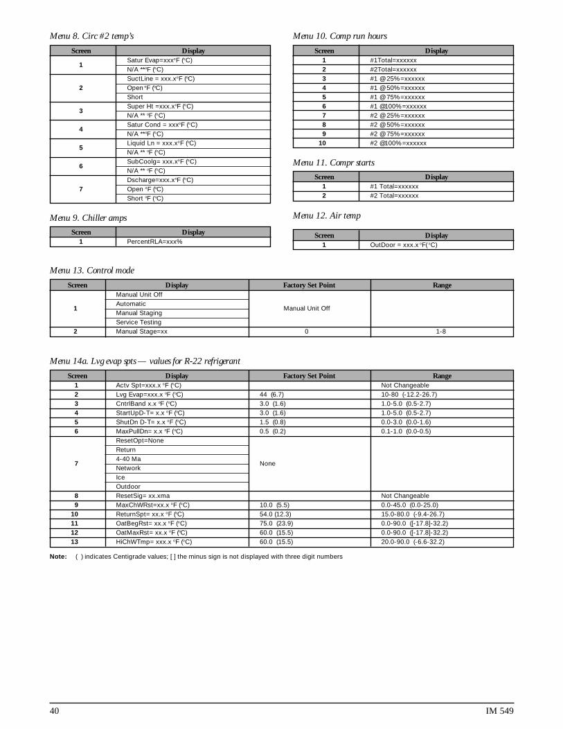
40 IM 549
Menu 14a. Lvg evap spts — values for R-22 refrigerant
Screen Display Factory Set Point Range1 Actv Spt=xxx.x oF (oC) Not Changeable2 Lvg Evap=xxx.x oF (oC) 44 (6.7) 10-80 (-12.2-26.7)3 CntrlBand x.x oF (oC) 3.0 (1.6) 1.0-5.0 (0.5-2.7)4 StartUpD-T= x.x oF (oC) 3.0 (1.6) 1.0-5.0 (0.5-2.7)5 ShutDn D-T= x.x oF (oC) 1.5 (0.8) 0.0-3.0 (0.0-1.6)6 MaxPullDn= x.x oF (oC) 0.5 (0.2) 0.1-1.0 (0.0-0.5)
ResetOpt=NoneReturn
74-40 Ma
NoneNetworkIceOutdoor
8 ResetSig= xx.xma Not Changeable9 MaxChWRst=xx.x oF (oC) 10.0 (5.5) 0.0-45.0 (0.0-25.0)
10 ReturnSpt= xx.x oF (oC) 54.0 (12.3) 15.0-80.0 (-9.4-26.7)11 OatBegRst= xx.x oF (oC) 75.0 (23.9) 0.0-90.0 ([-17.8]-32.2)12 OatMaxRst= xx.x oF (oC) 60.0 (15.5) 0.0-90.0 ([-17.8]-32.2)13 HiChWTmp= xxx.x oF (oC) 60.0 (15.5) 20.0-90.0 (-6.6-32.2)
Note: ( ) indicates Centigrade values; [ ] the minus sign is not displayed with three digit numbers
Menu 8. Circ #2 temp’s
Menu 9. Chiller amps
Menu 10. Comp run hours
Menu 11. Compr starts
Menu 12. Air temp
Menu 13. Control mode
Screen Display Factory Set Point RangeManual Unit Off
1Automatic
Manual Unit OffManual StagingService Testing
2 Manual Stage=xx 0 1-8
Screen Display1 OutDoor = xxx.x oF( oC)
Screen Display1 #1 Total=xxxxxx2 #2 Total=xxxxxx
Screen Display1 #1Total=xxxxxx2 #2Total=xxxxxx3 #1 @ 25%=xxxxxx4 #1 @ 50%=xxxxxx5 #1 @ 75%=xxxxxx6 #1 @100%=xxxxxx7 #2 @ 25%=xxxxxx8 #2 @ 50%=xxxxxx9 #2 @ 75%=xxxxxx
10 #2 @100%=xxxxxx
Screen Display1 PercentRLA=xxx%
Screen Display
1Satur Evap=xxxoF (oC)N/A **oF (oC)SuctLine = xxx.xoF (oC)
2 Open oF (oC)Short
3Super Ht =xxx.xoF (oC)N/A ** oF (oC)
4Satur Cond = xxxoF (oC)N/A **oF (oC)
5Liquid Ln = xxx.xoF (oC)N/A ** oF (oC)
6SubCoolg= xxx.xoF (oC)N/A ** oF (oC)Dscharge=xxx.xoF (oC)
7 Open oF (oC)Short oF (oC)

IM 549 41
Menu 14b. Lvg evap spts — values for 134a refrigerant
Menu 15. Soft load spts
Menu 16. Compressor spt
Screen Display Factory Set Point Range1 Time Left= xxmin2 SoftLoad= xx min 20 0-2543 SoftLdMaxStg= x 7 1-84 LoadDelay= xxsec 15 0-254
Screen Display Factory Set Point Range1 LeadCircuit=Auto Auto #1-#22 InterStg= xxx sec 210 60-4803 MinST-ST=xx min 15 5-404 MinSP-ST xx min 5 3-30
Screen Display Factory Set Point Range1 Actv Spt=xxx.x oF (oC) Not Changeable2 Lvg Evap=xxx.x oF (oC) 44 (6.7) 10-80 (-6.6-26.7)3 CntrlBand x.x oF (oC) 3.0 (1.6) 1.0-5.0 (0.5-2.7)4 StartUpD-T= x.x oF (oC) 3.0 (1.6) 1.0-5.0 (0.5-2.7)5 ShutDn D-T= x.x oF (oC) 1.5 (0.8) 0.0-3.0 (0.0-1.6)6 MaxPullDn= x.x oF (oC) 0.5 (0.2) 0.1-1.0 (0.0-0.5)
ResetOpt=NoneReturn
74-40 Ma
NoneNetworkIceOutdoor
8 ResetSig= xx.xma Not Changeable9 MaxChWRst=xx.x oF (oC) 10.0 (5.5) 0.0-45.0 (0.0-25.0)
10 ReturnSpt= xx.x oF (oC) 54.0 (12.3) 15.0-80.0 (-9.4-26.7)11 OaTBegRst= xx.x oF (oC) 75.0 (23.9) 0.0-90.0 (-3.9-32.2)12 OatMaxRst= xx.x oF (oC) 60.0 (15.5) 0.0-90.0 ([-17.8]-32.2)13 HiChWTmp= xxx.x oF (oC) 60.0 (15.5) 20.0-90.0 (-6.6-32.2)
Note: ( ) indicates Centigrade values; [ ] the minus sign is not displayed with three digit numbers
Menu 17a. Head pres spt — values for R-22 refrigerant
Notes: ( ) indicates Centigrade values
Menu 17b. Head pres spt — values for 134a refrigerant
Notes: ( ) indicates Centigrade values
Menu 18. Demand limits
Menu 19. Time/date
Screen Display Factory Set Point Range1 MinLift 25%=xxx 70 (483) 60-100 (414-690)2 MinLift 50%=xxx 80 (552) 70-100 (483-690)3 MinLift100%=xxx 140 (966) 100-140 (690-966)4 DeadBandMult= x.x 1.0 .8-1.35 StageUpErr= xxx 400 (2760) 300-990 (2070-6830)6 StageDnErr = xxx 100 (690) 50-400 (340-2760)
Screen Display Factory Set Point Range1 MinLift 25%=xxx 50 (345) 40-60 (276-414)2 MinLift 50%=xxx 56 (386) 50-80 (345-552)3 MinLift100%=xxx 90 (621) 80-122 (552-841)4 DeadBandMult= x.x 1.0 .8-1.35 StageUpErr= xxx 400 (2760) 300-990 (2070-6830)6 StageDnErr = xxx 100 (690) 50-400 (340-2760)
Screen Display Factory Set Point Range1 Demand Lim= xstg 3 Not Changeable at this screen
2 DemandSg= xx.x ma Actual Value Indicates the Magnitude of the DemandLimit Signal
Screen Display Factory Set Point Range1 Time= xx:xx:xx Actual Time2 Mon xx/xx/xx Actual Day and Date

42 IM 549
Menu 21. Holiday date
Menu 22. Service test
Screen Display Factory Set Point Range1 #0 Output 0=Off Off On-Off2 #1 Output 1=Off Off On-Off3 #2 EXV Pos#1=xxx 0-7604 #3 EXV Pos#2=xxx 0-7605 #4 Output 4=Off Off On-Off6 #5 Output 5=Off Off On-Off7 #6 Output 6=Off Off On-Off8 #7 Output 7=Off Off On-Off9 #8 Output 8=Off Off On-Off
10 #9 Output 9=Off Off On-Off11 #10 Output 10=Off Off On-Off12 #11 Output 11=Off Off On-Off13 #12 Output 12=Off Off On-Off14 #13 Output 13=Off Off On-Off15 #14 Output 14=Off Off On-Off16 #15 Output 15=Off Off On-Off17 #16 Output 16=Off Off On-Off18 #17 Output 17=Off Off On-Off19 #18 Output 18=Off Off On-Off20 #19 Output 19=Off Off On-Off21 #20 DH1=00000000 Digital Input ( 0-Open ) ( 1-Closed )22 #21 DH2=00000000 Digital Input ( 0-Open ) ( 1-Closed )23 #22 AI#5= x.xx Vdc Actual Vdc Value
Screen Display Factory Set Point Range1 #1 Date = N/A 0 N/A 0 Jan-Dec 1-312 #1 Dur = 0 Day(s) 0 0-313 #2 Date = N/A 0 N/A 0 Jan-Dec 1-314 #2 Dur = 0 Day(s) 0 0-315 #3 Date = N/A 0 N/A 0 Jan-Dec 1-316 #3 Dur = 0 Day(s) 0 0-317 #4 Date = N/A 0 N/A 0 Jan-Dec 1-318 #4 Dur = 0 Day(s) 0 0-319 #5 Date = N/A 0 N/A 0 Jan-Dec 1-31
10 #5 Dur = 0 Day(s) 0 0-3111 #6 Date = N/A 0 N/A 0 Jan-Dec 1-3112 #6 Dur = 0 Day(s) 0 0-3113 #7 Date = N/A 0 N/A 0 Jan-Dec 1-3114 #7 Dur = 0 Day(s) 0 0-3115 #8 Date = N/A 0 N/A 0 Jan-Dec 1-3116 #8 Dur = 0 Day(s) 0 0-3117 #9 Date = N/A 0 N/A 0 Jan-Dec 1-3118 #9 Dur = 0 Day(s) 0 0-3119 #10 Date = N/A 0 N/A 0 Jan-Dec 1-3120 #10 Dur = 0 Day(s) 0 0-3121 #11 Date = N/A 0 N/A 0 Jan-Dec 1-3122 #11 Dur = 0 Day(s) 0 0-3123 #12 Date = N/A 0 N/A 0 Jan-Dec 1-3124 #12 Dur = 0 Day(s) 0 0-3125 #13 Date = N/A 0 N/A 0 Jan-Dec 1-3126 #13 Dur = 0 Day(s) 0 0-3127 #14 Date = N/A 0 N/A 0 Jan-Dec 1-3128 #14 Dur = 0 Day(s) 0 0-31
Menu 20. Schedule
Screen Display Factory Set Point Range1 Override= xx.xx hr 0.00 Hr 00:00-63.502 NMPSchedule= N/A N/A 1-323 Sun 00:00-23:59 00:00-23:59 00:00-23:594 Mon 00:00-23:59 00:00-23:59 00:00-23:595 Tue 00:00-23:59 00:00-23:59 00:00-23:596 Wed 00:00-23:59 00:00-23:59 00:00-23:597 Thu 00:00-23:59 00:00-23:59 00:00-23:598 Fri 00:00-23:59 00:00-23:59 00:00-23:599 Sat 00:00-23:59 00:00-23:59 00:00-23:59
10 Hol 00:00-23:59 00:00-23:59 00:00-23:59

IM 549 43
Menu 25. #1 curr alarm
Screen Display1 Current Alarm2 @ 0:00 0/00/003 Evap = x.x psi (kPa)4 Cond = x.x psi (kPa)5 SuctLine=xxx.x oF(oC)6 LiquisLn=xxx.x oF(oC)7 Evap Lvg=xxx.x oF(oC)8 OA/LCnWT=xx.xxoF(oC)9 Capacity= xxx%
10 Fan Stage = x
Menu 26. #2 curr alarm
Screen Display1 Current Alarm2 @ 0:00 0/00/003 Evap = x.x psi (kPa)4 Cond = x.x psi (kPa)5 SuctLine=xxx.x oF(oC)6 LiquisLn=xxx.x oF(oC)7 Evap Lvg=xxx.x oF(oC)8 OA/LCnWT=xx.xxoF(oC)9 Capacity= xxx%
10 Fan Stage = x
Menu 23a. Alarm spts — values for R-22 refrigerant
Screen Display Factory Set Point Range1 StpPumpDn =xxpsi (kPa) 34 (234) 2-54 (13-372)2 FullPumpDown= No No No-yes3 FreezStat= xxpsi (kPa) 54 (372) 20-60 (138-414)4 FreezH2O= xx.x oF (oC) 36.0 (2.3) 0.0-40.0 (-17.5-4.5)5 Hi Press = xxxpsi (kPa) 380 (2622) 280-426 (1932-2939)
Note: ( ) indicates Centigrade value
Menu 23b. Alarm spts — values for 134a refrigerant
Screen Display Factory Set Point Range1 StpPumpDn =xxpsi (kPa) 14 (96) 2-22 (13-151)2 FullPumpDown= No No No-yes3 FreezStat= xxpsi (kPa) 26 (179) 4-26 (27-179)4 FreezH2O= xx.x oF (oC) 36.0 (2.3) 0.0-40.0 (-17.5-4.5)5 Hi Press = xxxpsi (kPa) 276 (1904) 180-326 (1242-2249)
Note: ( ) indicates Centigrade value
Menu 24. Misc setup
Screen Display Factory Set Point RangeUnit Type= ALS125ALS140ALS155ALS170ALS175
1ALS185ALS195PFS150PFS165PFS180PFS190PFS200
2 Units = English English English-Metric3 SpeedTrol = No No No-Yes4 Power = 60 hz 60 60-505 Port A Baud=xxxx 9600 9600-2400-1200
Pre-Alarm=Blink6 Open Blink Blink-Open-Closed
ClosedAlarm=Closed
7 Blink(N/O) Closed Closed-Blink(N/O)-Blink(N/C)Blink(N/C)OAT Select=None
8 Lcl None None-Lcl-RmtRmt
9 LvgEvpAdj= 0.0 oF(oC) -0.8-0.8 (-0.4-0.5)8 EntEvpAdj= 0.0 oF(oC) -0.8-0.8 (-0.4-0.5)
11 #1EvpAdj= 0.0psi (kPa) (-13.8-13.8)13 #2EvpAdj= 0.0psi (kPa) (-13.8-13.8)12 #1CndAdj= 0.0psi (kPa) (-13.8-13.8)13 #2CndAdj= 0.0psi (kPa) (-13.8-13.8)14 Refrigerant= R22 Not Changeable15 IDENT = SC2-X18B Not Changeable

44 IM 549
Menu 27. #1 Prev alarm
Screen Display1 1 Current Alarm2 1 x:xx x/xx/xx3 2 Current Alarm4 2 x:xx x/xx/xx5 3 Current Alarm6 3 x:xx x/xx/xx7 4 Current Alarm8 4 x:xx x/xx/xx9 5 Current Alarm
10 5 x:xx x/xx/xx
Menu 28. #2 Prev alarm
Screen Display1 1 Current Alarm2 1 x:xx x/xx/xx3 2 Current Alarm4 2 x:xx x/xx/xx5 3 Current Alarm6 3 x:xx x/xx/xx7 4 Current Alarm8 4 x:xx x/xx/xx9 5 Current Alarm
10 5 x:xx x/xx/xx
Menu 1. Chiller status
Menus for Three (3) Screw Compressors Units
Screen DisplayOFF: Manual ModeSystem SwRemote CommRemote SwTime ClockAlarm
1 PumpDnSw’sStartingWaitForLoadCoolStageDnCoolStageUpCoolStaging #Manual Cool
2 InterStg=xxx sec3 Hold Stage min4 Hi Loop Temp=
Menu 2. Circ #1 status
Screen DisplayOFF: SystemSwManualMdeAlarmPumpDwnSwCycleTime xxWaitFlooded
1waitFlodded xxxReadyPumpingDownStartingPre-PurgeOpened EXVLowAmbStartCooling %Cap=xxx
Menu 3. Circ #2 status
Screen DisplayOFF: SystemSwManualMdeAlarmPumpDwnSwCycleTime xxWaitFlooded
1waitFlodded xxxReadyPumpingDownStartingPre-PurgeOpened EXVLowAmbStartCooling %Cap=xxx
Menu 4. Circ #3 status
Screen DisplayOFF: SystemSwManualMdeAlarmPumpDwnSwCycleTime xxWaitFlooded
1waitFlodded xxxReadyPumpingDownStartingPre-PurgeOpened EXVLowAmbStartCooling %Cap=xxx

IM 549 45
Menu 5. Water temp’s
Screen DisplayLvg Evap= xxx.x oF (oC)
1 Short oF (oC)Open oF (oC)Ent Evap= xxx.x oF (oC)
2 Short oF (oC)Open oF (oC)Ent Cond= xxx.x oF (oC)
3 Short oF (oC)Open oF (oC)Lvg Cond= xxx.x oF (oC)
4 Short oF (oC)Open oF (oC)
Menu 6. Circ #1 pres’s
Screen DisplayEvap= xxx.x psi(kPa) xxoF (oC)
1Evap 145 +psi(kPa) **oF (oC)Open N/A ** oF (oC)Short N/A **oF (oC)Cond xxx.x psi (kPa) xxxo
2Cond 450+ psi (kPa) xxxo
Open N/A **oF (oC)Short N/A **oF (oC)
3 MinCondPr = 0#4 MaxCondPr = 0#5 EXV Position= xxx6 Cond Fan Stage = x
Menu 7. Circ #2 pres’s
Screen DisplayEvap= xxx.x psi(kPa) xxoF (oC)
1Evap 145 +psi(kPa) **oF (oC)Open N/A ** oF (oC)Short N/A **oF (oC)Cond xxx.x psi (kPa) xxxo
2Cond 450+ psi (kPa) xxxo
Open N/A ** oF (oC)Short N/A **oF (oC)
3 MinCondPr = 0#4 MaxCondPr = 0#5 EXV Position= xxx6 Cond Fan Stage = x
Menu 8. Circ #3 pres’s
Screen DisplayEvap= xxx.x psi(kPa) xxoF (oC)
1Evap 145 +psi(kPa) **oF (oC)Open N/A ** oF (oC)Short N/A **oF (oC)Cond xxx.x psi (kPa) xxxo
2Cond 450+ psi (kPa) xxxo
Open N/A ** oF (oC)Short N/A **oF (oC)
3 MinCondPr = 0#4 MaxCondPr = 0#5 EXV Position= xxx6 Cond Fan Stage = x
Menu 9. Circ #1 temp’s
Screen Display
1Satur Evap=xxxoF (oC)N/A **oF (oC)SuctLine = xxx.xoF (oC)
2 Open oF (oC)ShortoF (oC)
3Super Ht =xxx.xoF (oC)N/A ** oF (oC)
4Satur Cond = xxxoF (oC)N/A **oF (oC)
5Liquid Ln = xxx.xoF (oC)N/A ** oF (oC)
6SubCoolg= xxx.xoF (oC)N/A ** oF (oC)Dscharge=xxx.xoF (oC)
7 Open oF (oC)Short oF (oC)
Menu 10. Circ #2 temp’s
Screen Display
1Satur Evap=xxxoF (oC)N/A **oF (oC)SuctLine = xxx.xoF (oC)
2 Open oF (oC)ShortoF (oC)
3Super Ht =xxx.xoF (oC)N/A ** oF (oC)
4Satur Cond = xxxoF (oC)N/A **oF (oC)
5Liquid Ln = xxx.xoF (oC)N/A ** oF (oC)
6SubCoolg= xxx.xoF (oC)N/A ** oF (oC)Dscharge=xxx.xoF (oC)
7 Open oF (oC)Short oF (oC)
Menu 11. Circ #3 temp’s
Screen Display
1Satur Evap=xxxoF (oC)N/A **oF (oC)SuctLine = xxx.xoF (oC)
2 Open oF (oC)ShortoF (oC)
3Super Ht =xxx.xoF (oC)N/A ** oF (oC)
4Satur Cond = xxxoF (oC)N/A **oF (oC)
5Liquid Ln = xxx.xoF (oC)N/A ** oF (oC)
6SubCoolg= xxx.xoF (oC)N/A ** oF (oC)Dscharge=xxx.xoF (oC)
7 Open oF (oC)Short oF (oC)
Menu 12. Chiller amps
Screen Display
1#1 PrcntRLA=xxx%N/A %
2#2 PrcntRLA=xxx%N/A %
3#3 PrcntRLA=xxx%N/A %

46 IM 549
Menu 13. Comp run hours
Screen Display1 #1Total=xxxxxx2 #2Total=xxxxxx3 #3Total=xxxxxx4 #1 @ 25%=xxxxxx5 #1 @ 50%=xxxxxx6 #1 @ 75%=xxxxxx7 #1 @100%=xxxxxx8 #2 @ 25%=xxxxxx9 #2 @ 50%=xxxxxx
10 #2 @ 75%=xxxxxx11 #2 @100%=xxxxxx12 #3 @ 25%=xxxxxx13 #3 @ 50%=xxxxxx14 #3 @ 75%=xxxxxx15 #3 @1005%=xxxxxx
Menu 14. Compr starts
Screen Display1 #1 Total=xxxxxx2 #2 Total=xxxxxx3 #3 Total=xxxxxx
Menu 15. Air temp
Screen Display1 OutDoor = xxx.x oF( oC)
Menu 16. Control mode
Screen Display Factory Set Point RangeManual Unit Off
1Automatic
Manual Unit OffManual StagingService Testing
Menu 17a. Lvg evap spts - values for R-22 refrigerant
Screen Display Factory Set Point Range1 Actv Spt=xxx.x oF (oC) Not Changeable2 Lvg Evap=xxx.x oF (oC) 44 (6.7) 10 - 80 (-12.2 - 26.7)3 CntrlBand x.x oF (oC) 3.0 (1.6) 1.0 - 5.0 (0.5 - 2.7)4 StartUpD-T= x.x oF (oC) 3.0 (1.6) 1.0 - 5.0 (0.5 - 2.7)5 ShutDn D-T= x.x oF (oC) 1.5 (0.8) 0.0 - 3.0 (0.0 - 1.6)6 MaxPullDn= x.x oF (oC) 0.5 (0.2) 0.1 - 1.0 (0.0 - 0.5)
ResetOpt=NoneReturn
74-40 Ma
NoneNetworkIceOutdoor
8 ResetSig= xx.xma Not Changeable9 MaxChWRst=xx.x oF (oC) 10.0 (5.5) 0.0 - 45.0 (0.0 - 25.0)
10 ReturnSpt= xx.x oF (oC) 54.0 (12.3) 15.0 - 80.0 (-9.4 - 26.7)11 No OaTRst= xx.x oF (oC) 75.0 (23.9) 0.0 - 90.0 ([-17.8] - 32.2)12 MaxOaTRst= xx.x oF (oC) 60.0 (15.5) 0.0 - 90.0 ([-17.8] - 32.2)13 HiChWTmp= xxx.x oF (oC) 60.0 (15.5) 20.0 - 90.0 (-6.6 - 32.2)14 Amb Lock= xxx.x oF (oC) 30.0 (-1.1) 0.0 - 90.0 (-17.8 - 32.2)
Note: [ ] the minus sign is not displayed with three digit numbers; ( ) indicates Centigrade values.

IM 549 47
Menu 17b. Lvg evap spts — values for 134a refrigerant
Screen Display Factory Set Point Range1 Actv Spt=xxx.x oF (oC) Not Changeable2 Lvg Evap=xxx.x oF (oC) 44 (6.7) 10-80 (-6.6-26.7)3 CntrlBand x.x oF (oC) 3.0 (1.6) 1.0-5.0 (0.5-2.7)4 StartUpD-T= x.x oF (oC) 3.0 (1.6) 1.0-5.0 (0.5-2.7)5 ShutDn D-T= x.x oF (oC) 1.5 (0.8) 0.0-3.0 (0.0-1.6)6 MaxPullDn= x.x oF (oC) 0.5 (0.2) 0.1-1.0 (0.0-0.5)
ResetOpt=NoneReturn
74-40 Ma
NoneNetworkIceOutdoor
8 ResetSig= xx.xma Not Changeable9 MaxChWRst=xx.x oF (oC) 10.0 (5.5) 0.0-45.0 (0.0-25.0)
10 ReturnSpt= xx.x oF (oC) 54.0 (12.3) 15.0-80.0 (-9.4-26.7)11 No OaTRst= xx.x oF (oC) 75.0 (23.9) 0.0-90.0 (-3.9-32.2)12 MaxOaTRst= xx.x oF (oC) 60.0 (15.5) 0.0-90.0 ([-17.8]-32.2)13 HiChWTmp= xxx.x oF (oC) 60.0 (15.5) 20.0-90.0 (-6.6-32.2)14 Amb Lock= xxx.x oF (oC) 30.0 (-1.1) 0.0-90.0 (-17.8-32.2)
Note: [ ] the minus sign is not displayed with three digit numbers; ( ) indicates Centigrade values.
Menu 20a. Head pres spt — values for R-22 refrigerant
Screen Display Factory Set Point Range1 MinLift 25%=xxx 70 (483) 60-100 (414-690)2 MinLift 50%=xxx 80 (552) 70-100 (483-690)3 MinLift100%=xxx 140 (966) 100-140 (690-966)4 DeadBandMult= x.x 1.0 .8-1.35 StageUpErr= xxx 400 (2760) 300-990 (2070-6830)6 StageDnErr = xxx 100 (690) 50-400 (340-2760)
Note: ( ) indicates Centigrade values.
Menu 20b. Head pres spt — values for 134a refrigerant
Screen Display Factory Set Point Range1 MinLift 25%=xxx 50 (345) 40-60 (276-414)2 MinLift 50%=xxx 56 (386) 50-80 (345-552)3 MinLift100%=xxx 90 (621) 80-122 (552-841)4 DeadBandMult= x.x 1.0 .8-1.35 StageUpErr= xxx 400 (2760) 300-990 (2070-6830)6 StageDnErr = xxx 100 (690) 50-400 (340-2760)
Note: ( ) indicates Centigrade values.
Menu 18. Soft load spts
Screen Display Factory Set Point Range1 Time Left= xxmin2 SoftLoad= xx min 20 0-2543 SoftLdMaxStg= x 7 1-84 LoadDelay= xxsec 15 0-254
Menu 19. Compressor spt
Screen Display Factory Set Point RangeLead/Lag=Auto1->2->31->3->2
1 2->1->3 Auto2->3->13->1->23->2->1
2 InterStg= xxx sec 210 60-4803 MinST-ST=xx min 15 5-404 MinSP-ST xx min 5 3-30

48 IM 549
Menu 21. Demand limits
Screen Display Factory Set Point Range1 Demand Lim= xstg 3 Not Changeable at this screen
2 DemandSg= xx.x ma Actual Value Indicates the Magnitude of the DemandLimit Signal
Menu 22. Time/date
Screen Display Factory Set Point Range1 Time= xx:xx:xx Actual Time2 Mon xx/xx/xx Actual Day and Date
Menu 23. Schedule
Screen Display Factory Set Point Range1 Override= xx.xx hr 0.00 Hr 00:00-63.502 NMPSchedule= N/A N/A 1-323 Sun 00:00-23:59 00:00-23:59 00:00-23:594 Mon 00:00-23:59 00:00-23:59 00:00-23:595 Tue 00:00-23:59 00:00-23:59 00:00-23:596 Wed 00:00-23:59 00:00-23:59 00:00-23:597 Thu 00:00-23:59 00:00-23:59 00:00-23:598 Fri 00:00-23:59 00:00-23:59 00:00-23:599 Sat 00:00-23:59 00:00-23:59 00:00-23:59
10 Hol 00:00-23:59 00:00-23:59 00:00-23:59
Menu 24. Holiday date
Screen Display Factory Set Point Range1 #1 Date = N/A 0 N/A 0 Jan-Dec 1-312 #1 Dur = 0 Day(s) 0 0-313 #2 Date = N/A 0 N/A 0 Jan-Dec 1-314 #2 Dur = 0 Day(s) 0 0-315 #3 Date = N/A 0 N/A 0 Jan-Dec 1-316 #3 Dur = 0 Day(s) 0 0-317 #4 Date = N/A 0 N/A 0 Jan-Dec 1-318 #4 Dur = 0 Day(s) 0 0-319 #5 Date = N/A 0 N/A 0 Jan-Dec 1-31
10 #5 Dur = 0 Day(s) 0 0-3111 #6 Date = N/A 0 N/A 0 Jan-Dec 1-3112 #6 Dur = 0 Day(s) 0 0-3113 #7 Date = N/A 0 N/A 0 Jan-Dec 1-3114 #7 Dur = 0 Day(s) 0 0-3115 #8 Date = N/A 0 N/A 0 Jan-Dec 1-3116 #8 Dur = 0 Day(s) 0 0-3117 #9 Date = N/A 0 N/A 0 Jan-Dec 1-3118 #9 Dur = 0 Day(s) 0 0-3119 #10 Date = N/A 0 N/A 0 Jan-Dec 1-3120 #10 Dur = 0 Day(s) 0 0-3121 #11 Date = N/A 0 N/A 0 Jan-Dec 1-3122 #11 Dur = 0 Day(s) 0 0-3123 #12 Date = N/A 0 N/A 0 Jan-Dec 1-3124 #12 Dur = 0 Day(s) 0 0-3125 #13 Date = N/A 0 N/A 0 Jan-Dec 1-3126 #13 Dur = 0 Day(s) 0 0-3127 #14 Date = N/A 0 N/A 0 Jan-Dec 1-3128 #14 Dur = 0 Day(s) 0 0-31

IM 549 49
Menu 25. Service test
Screen Display Factory Set Point Range1 #0 Output 0=Off Off On-Off2 #1 Output 1=Off Off On-Off3 #2 EXV Pos#1=xxx 0-7604 #3 EXV Pos#2=xxx 0-7605 #4 EXV Pos#3=xxx 0-7606 #5 Output 4=Off Off On-Off7 #6 Output 5=Off Off On-Off8 #7 Output 6=Off Off On-Off9 #8 Output 7=Off Off On-Off
10 #9 Output 8=Off Off On-Off11 #10 Output 9=Off Off On-Off12 #11 Output 10=Off Off On-Off13 #12 Output 11=Off Off On-Off14 #13 Output 12=Off Off On-Off15 #14 Output 13=Off Off On-Off16 #15 Output 14=Off Off On-Off17 #16 Output 15=Off Off On-Off18 #17 Output 16=Off Off On-Off19 #18 Output 17=Off Off On-Off20 #19 Output 18=Off Off On-Off21 #20 Output 19=Off Off On-Off22 #21 Output 20=Off Off On-Off23 #22 Output 21=Off Off On-Off24 #23 Output 22=Off Off On-Off25 #24 Output 23=Off Off On-Off26 #25 Output 24=Off Off On-Off27 #26 Output 25=Off Off On-Off28 #27 Output 26=Off Off On-Off29 #28 Output 27=Off Off On-Off30 #29 DH1=00000000 Digital Input ( 0-Open ) ( 1-Closed )31 #30 DH2=00000000 Digital Input ( 0-Open ) ( 1-Closed )32 #31 DH3=00000000 Digital Input ( 0-Open ) ( 1-Closed )33 #32 AI#5= x.xx Vdc Actual Vdc Value
Menu 26a. Alarm spts — values for R-22 refrigerant
Screen Display Factory Set Point Range1 StpPumpDn =xxpsi (kPa) 34 (234) 2 - 54 (13-372)2 FullPumpDown= No No No - yes3 FreezStat= xxpsi (kPa) 54 (372) 20 - 60 (138-414)4 FreezH2O= xx.x oF (oC) 36.0 (2.3) 0.0 - 40.0 (-17.5-4.5)5 Hi Press = xxxpsi (kPa) 380 (2622) 280 - 426 (1932-2939)
Note: ( ) indicates Centigrade values
Menu 26b. Alarm spts — values for 134a refrigerant
Screen Display Factory Set Point Range1 StpPumpDn =xxpsi (kPa) 14 (96) 2 - 22 (13-151)2 FullPumpDown= No No No - yes3 FreezStat= xxpsi (kPa) 26 (179) 4 - 26 (27-179)4 FreezH2O= xx.x oF (oC) 36.0 (2.3) 0.0 - 40.0 (-17.5-4.5)5 Hi Press = xxxpsi (kPa) 276 (1904) 180 - 326 (1242-2249)
Note: ( ) indicates Centigrade values

50 IM 549
Menu 30. #3 curr alarm
Screen Display1 Current Alarm2 @ 0:00 0/00/003 Evap = x.x psi (kPa)4 Cond = x.x psi (kPa)5 SuctLine=xxx.x oF(oC)6 LiquisLn=xxx.x oF(oC)7 Evap Lvg=xxx.x oF(oC)8 OutsideA=xxx.x oF(o)9 Capacity= xxx%
10 Fan Stage = x
Menu 31. #1 prev alarm
Screen Display1 1 Current Alarm2 1 x:xx x/xx/xx3 2 Current Alarm4 2 x:xx x/xx/xx5 3 Current Alarm6 3 x:xx x/xx/xx7 4 Current Alarm
8 4 x:xx x/xx/xx9 5 Current Alarm
10 5 x:xx x/xx/xx
Menu 27. Misc setup
Screen Display Factory Set Point RangeUnit Type= ALS205ALS220
1ALS235ALS250ALS265ALS280
2 Units = English English English-Metric3 SpeedTrol = No No No-Yes4 Power = 60 hz 60 60-505 Port A Baud=xxxx 9600 9600-2400-1200
Pre-Alarm=Blink6 Open Blink Blink-Open-Closed
ClosedAlarm=Closed
7 Blink(N/O) Closed Closed-Blink(N/O)-Blink(N/C)Blink(N/C)OAT Select=None
8 Lcl None None-Lcl-RmtRmt
9Amb Lockout= No
No No-YesYes
10 LvgEvpAdj= 0.0 oF(oC) -0.8-0.8 (-0.4-0.5)11 EntEvpAdj= 0.0 oF(oC) -0.8-0.8 (-0.4-0.5)12 #1EvpAdj= 0.0psi (kPa) -2.0-2.0 (-13.8-13.8)13 #2EvpAdj= 0.0psi (kPa) -2.0-2.0 (-13.8-13.8)14 #3EvpAdj= 0.0psi (kPa) -2.0-2.0 (-13.8-13.8)15 #1CndAdj= 0.0psi (kPa) -2.0-2.0 (-13.8-13.8)16 #2CndAdj= 0.0psi (kPa) -2.0-2.0 (-13.8-13.8)17 #3CndAdj= 0.0psi (kPa) -2.0-2.0 (-13.8-13.8)18 Refrigerant= R22 Not Changeable19 IDENT = SC32U19A Not Changeable
Menu 28. #1 curr alarm
Screen Display1 Current Alarm2 @ 0:00 0/00/003 Evap = x.x psi (kPa)4 Cond = x.x psi (kPa)5 SuctLine=xxx.x oF(oC)6 LiquisLn=xxx.x oF(oC)7 Evap Lvg=xxx.x oF(oC)8 OutsideA=xxx.x oF(oC)9 Capacity= xxx%
10 Fan Stage = x
Menu 29. #2 curr alarm
Screen Display1 Current Alarm2 @ 0:00 0/00/003 Evap = x.x psi (kPa)4 Cond = x.x psi (kPa)5 SuctLine=xxx.x oF(oC)
6 LiquisLn=xxx.x oF(oC)7 Evap Lvg=xxx.x oF(oC)8 OutsideA=xxx.x oF(oC)9 Capacity= xxx%
10 Fan Stage = x

IM 549 51
Menu 32. #2 prev alarm
Screen Display1 1 Current Alarm2 1 x:xx x/xx/xx3 2 Current Alarm4 2 x:xx x/xx/xx5 3 Current Alarm6 3 x:xx x/xx/xx7 4 Current Alarm8 4 x:xx x/xx/xx9 5 Current Alarm
10 5 x:xx x/xx/xx
Menu 33. #3 prev alarm
Screen Display1 1 Current Alarm2 1 x:xx x/xx/xx3 2 Current Alarm4 2 x:xx x/xx/xx5 3 Current Alarm6 3 x:xx x/xx/xx7 4 Current Alarm8 4 x:xx x/xx/xx9 5 Current Alarm
10 5 x:xx x/xx/xx
Menu 1. Chiller status
Menus for Four (4) Screw Compressors Units
Screen DisplayOFF: Manual ModeSystem SwRemote CommRemote SwTime ClockAlarm
1 PumpDnSw’sStartingWaitForLoadCoolStageDnCoolStageUpCoolStaging #Manual Cool
2 InterStg=xxx sec3 Hold Stage min4 Hi Loop Temp=
Menu 2. Circ #1 status
Screen DisplayOFF: SystemSwManualMdeAlarmPumpDwnSwCycleTime xxWaitFlooded
1waitFlodded xxxReadyPumpingDownStartingPre-PurgeOpened EXVLowAmbStartCooling %Cap=xxx
Menu 3. Circ #2 status
Screen DisplayOFF: SystemSwManualMdeAlarmPumpDwnSwCycleTime xxWaitFlooded
1waitFlodded xxxReadyPumpingDownStartingPre-PurgeOpened EXVLowAmbStartCooling %Cap=xxx
Menu 4. Circ #3 status
Screen DisplayOFF: SystemSwManualMdeAlarmPumpDwnSwCycleTime xxWaitFlooded
1waitFlodded xxxReadyPumpingDownStartingPre-PurgeOpened EXVLowAmbStartCooling %Cap=xxx

52 IM 549
Menu 5. Circ #4 status
Screen DisplayOFF: SystemSwManualMdeAlarmPumpDwnSwCycleTime xxWaitFlooded
1waitFlodded xxxReadyPumpingDownStartingPre-PurgeOpened EXVLowAmbStartCooling %Cap=xxx
Menu 6. Water temp’s
Screen DisplayLvg Evap= xxx.x oF (oC)
1 Short oF (oC)Open oF (oC)Ent Evap= xxx.x oF (oC)
2 Short oF (oC)Open oF (oC)Ent Cond= xxx.x oF (oC)
3 Short oF (oC)Open oF (oC)Lvg Cond= xxx.x oF (oC)
4 Short oF (oC)Open oF (oC)
Menu 7. Circ #1 pres’s
Screen DisplayEvap= xxx.x psi(kPa) xxoF (oC)
1Evap 145 +psi(kPa) **oF (oC)Open N/A ** oF (oC)Short N/A **oF (oC)Cond xxx.x psi (kPa) xxxo
2Cond 450+ psi (kPa) xxxo
Open N/A ** oF (oC)Short N/A **oF (oC)
3 MinCondPr = 0#4 MaxCondPr = 0#5 EXV Position= xxx6 Cond Fan Stage = x
Menu 8. Circ #2 pres’s
Screen DisplayEvap= xxx.x psi(kPa) xxoF (oC)
1Evap 145 +psi(kPa) **oF (oC)Open N/A ** oF (oC)Short N/A **oF (oC)Cond xxx.x psi (kPa) xxxo
2Cond 450+ psi (kPa) xxxo
Open N/A ** oF (oC)Short N/A **oF (oC)
3 MinCondPr = 0#4 MaxCondPr = 0#5 EXV Position= xxx6 Cond Fan Stage = x
Menu 9. Circ #3 pres’s
Screen DisplayEvap= xxx.x psi(kPa) xxoF (oC)
1Evap 145 +psi(kPa) **oF (oC)Open N/A ** oF (oC)Short N/A **oF (oC)Cond xxx.x psi (kPa) xxxo
2Cond 450+ psi (kPa) xxxo
Open N/A ** oF (oC)Short N/A **oF (oC)
3 MinCondPr = 0#4 MaxCondPr = 0#5 EXV Position= xxx6 Cond Fan Stage = x
Menu 10. Circ #4 pres’s
Screen DisplayEvap= xxx.x psi(kPa) xxoF (oC)
1Evap 145 +psi(kPa) **oF (oC)Open N/A ** oF (oC)Short N/A **oF (oC)Cond xxx.x psi (kPa) xxxo
2Cond 450+ psi (kPa) xxxo
Open N/A ** oF (oC)Short N/A **oF (oC)
3 MinCondPr = 0#4 MaxCondPr = 0#5 EXV Position= xxx6 Cond Fan Stage = x
Menu 11. Circ #1 temp’s
Screen Display
1Satur Evap=xxxoF (oC)N/A **oF (oC)SuctLine = xxx.xoF (oC)
2 Open oF (oC)ShortoF (oC)
3Super Ht =xxx.xoF (oC)N/A ** oF (oC)
4Satur Cond = xxxoF (oC)N/A **oF (oC)
5Liquid Ln = xxx.xoF (oC)N/A ** oF (oC)
6SubCoolg= xxx.xoF (oC)N/A ** oF (oC)Dscharge=xxx.xoF (oC)
7 Open oF (oC)Short oF (oC)
Menu 12. Circ #2 temp’s
Screen Display
1Satur Evap=xxxoF (oC)N/A **oF (oC)SuctLine = xxx.xoF (oC)
2 Open oF (oC)ShortoF (oC)
3Super Ht =xxx.xoF (oC)N/A ** oF (oC)
4Satur Cond = xxxoF (oC)N/A **oF (oC)
5Liquid Ln = xxx.xoF (oC)N/A ** oF (oC)
6SubCoolg= xxx.xoF (oC)N/A ** oF (oC)Dscharge=xxx.xoF (oC)
7 Open oF (oC)Short oF (oC)

IM 549 53
Menu 19. Control mode
Screen Display Factory Set Point RangeManual Unit Off
1Automatic
Manual Unit OffManual StagingService Testing
2 Manual Stage=xx 0 1-163 Circ 1 Mode=Auto Auto Auto-Off4 Circ 2 Mode=Auto Auto Auto-Off5 Circ 3 Mode=Auto Auto Auto-Off6 Circ 4Mode=Auto Auto Auto-Off
Menu 13. Circ #3 temp’s
Screen Display
1Satur Evap=xxxoF (oC)N/A **oF (oC)SuctLine = xxx.xoF (oC)
2 Open oF (oC)ShortoF (oC)
3Super Ht =xxx.xoF (oC)N/A ** oF (oC)
4Satur Cond = xxxoF (oC)N/A **oF (oC)
5Liquid Ln = xxx.xoF (oC)N/A ** oF (oC)
6SubCoolg= xxx.xoF (oC)N/A ** oF (oC)Dscharge=xxx.xoF (oC)
7 Open oF (oC)Short oF (oC)
Menu 15. Chiller amps
Screen Display
1#1&3 PctRLA=xxx%N/A %
2#2&4 PctRLA=xxx%N/A %
Menu 14. Circ #4 temp’s
Screen Display
1Satur Evap=xxxoF (oC)N/A **oF (oC)SuctLine = xxx.xoF (oC)
2 Open oF (oC)ShortoF (oC)
3Super Ht =xxx.xoF (oC)N/A ** oF (oC)
4Satur Cond = xxxoF (oC)N/A **oF (oC)
5Liquid Ln = xxx.xoF (oC)N/A ** oF (oC)
6SubCoolg= xxx.xoF (oC)N/A ** oF (oC)Dscharge=xxx.xoF (oC)
7 Open oF (oC)Short oF (oC)
Menu 16. Comp run hours
Screen Display1 #1Total=xxxxxx2 #2Total=xxxxxx3 #3Total=xxxxxx4 #4Total=xxxxxx5 #1 @ 25%=xxxxxx6 #1 @ 50%=xxxxxx7 #1 @ 75%=xxxxxx8 #1 @100%=xxxxxx9 #2 @ 25%=xxxxxx
10 #2 @ 50%=xxxxxx11 #2 @ 75%=xxxxxx12 #2 @100%=xxxxxx13 #3 @ 25%=xxxxxx14 #3 @ 50%=xxxxxx15 #3 @ 75%=xxxxxx16 #3 @1005%=xxxxxx17 #4 @ 25%=xxxxxx18 #4 @ 505%=xxxxxx19 #4 @ 75%=xxxxxx20 #4 @1005%=xxxxxx
Menu 17. Compr starts
Screen Display1 #1 Total=xxxxxx2 #2 Total=xxxxxx3 #3 Total=xxxxxx4 #4 Total=xxxxxx
Menu 18. Air temp
Screen Display1 OutDoor = xxx.x oF( oC)

54 IM 549
Menu 20a. Lvg evap spts — values for R-22 refrigerant
Screen Display Factory Set Point Range1 Actv Spt=xxx.x oF (oC) Not Changeable2 Lvg Evap=xxx.x oF (oC) 44 (6.7) 10-80 (-12.2-26.7)3 CntrlBand x.x oF (oC) 3.0 (1.6) 1.0-5.0 (0.5-2.7)4 StartUpD-T= x.x oF (oC) 3.0 (1.6) 1.0-5.0 (0.5-2.7)5 ShutDn D-T= x.x oF (oC) 1.5 (0.8) 0.0-3.0 (0.0-1.6)6 MaxPullDn= x.x oF (oC) 0.5 (0.2) 0.1-1.0 (0.0-0.5)
ResetOpt=NoneReturn
74-40 Ma
NoneNetworkIceOutdoor
8 ResetSig= xx.xma Not Changeable9 MaxChWRst=xx.x oF (oC) 10.0 (5.5) 0.0-45.0 (0.0-25.0)
10 ReturnSpt= xx.x oF (oC) 54.0 (12.3) 15.0-80.0 (-9.4-26.7)11 OatBegRst= xx.x oF (oC) 75.0 (23.9) 0.0-90.0 ([-17.8]-32.2)12 OatMaxRst= xx.x oF (oC) 60.0 (15.5) 0.0-90.0 ([-17.8]-32.2)13 HiChWTmp= xxx.x oF (oC) 60.0 (15.5) 20.0-90.0 (-6.6-32.2)14 Amb Lock= xxx.x oF (oC) 30.0 (-1.1) 0.0-90.0 (-17.8-32.2)
Note: [ ] the minus sign is not displayed with three digit numbers ( ) indicates Centigrade values.
Menu 20b. Lvg evap spts — values for 134a refrigerant
Screen Display Factory Set Point Range1 Actv Spt=xxx.x oF (oC) Not Changeable2 Lvg Evap=xxx.x oF (oC) 44 (6.7) 10-80 (-6.6-26.7)3 CntrlBand x.x oF (oC) 3.0 (1.6) 1.0-5.0 (0.5-2.7)4 StartUpD-T= x.x oF (oC) 3.0 (1.6) 1.0-5.0 (0.5-2.7)5 ShutDn D-T= x.x oF (oC) 1.5 (0.8) 0.0-3.0 (0.0-1.6)6 MaxPullDn= x.x oF (oC) 0.5 (0.2) 0.1-1.0 (0.0-0.5)
ResetOpt=NoneReturn
74-40 Ma
NoneNetworkIceOutdoor
8 ResetSig= xx.xma Not Changeable9 MaxChWRst=xx.x oF (oC) 10.0 (5.5) 0.0-45.0 (0.0-25.0)
10 ReturnSpt= xx.x oF (oC) 54.0 (12.3) 15.0-80.0 (-9.4-26.7)11 OaTBegRst= xx.x oF (oC) 75.0 (23.9) 0.0-90.0 (-3.9-32.2)12 OatMaxRst= xx.x oF (oC) 60.0 (15.5) 0.0-90.0 ([-17.8]-32.2)13 HiChWTmp= xxx.x oF (oC) 60.0 (15.5) 20.0-90.0 (-6.6-32.2)14 Amb Lock= xxx.x oF (oC) 30.0 (-1.1) 0.0-90.0 (-17.8-32.2)
Note: [ ] the minus sign is not displayed with three digit numbers ( ) indicates Centigrade values.
Menu 21. Soft load spts
Screen Display Factory Set Point Range1 Time Left= xxmin2 SoftLoad= xx min 20 0-2543 SoftLdMaxStg= x 7 1-84 LoadDelay= xxsec 15 0-254
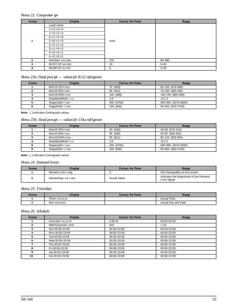
IM 549 55
Menu 23a. Head pres spt — values for R-22 refrigerant
Screen Display Factory Set Point Range1 MinLift 25%=xxx 70 (483) 60-100 (414-690)2 MinLift 50%=xxx 80 (552) 70-100 (483-690)3 MinLift100%=xxx 140 (966) 100-140 (690-966)4 DeadBandMult= x.x 1.0 .8-1.35 StageUpErr= xxx 400 (2760) 300-990 (2070-6830)6 StageDnErr = xxx 100 (690) 50-400 (340-2760)
Note: ( ) indicates Centrigrade values
Menu 23b. Head pres spt — values for 134a refrigerant
Screen Display Factory Set Point Range1 MinLift 25%=xxx 50 (345) 40-60 (276-414)2 MinLift 50%=xxx 56 (386) 50-80 (345-552)3 MinLift100%=xxx 90 (621) 80-122 (552-841)4 DeadBandMult= x.x 1.0 .8-1.35 StageUpErr= xxx 400 (2760) 300-990 (2070-6830)6 StageDnErr = xxx 100 (690) 50-400 (340-2760)
Note: ( ) indicates Centrigrade values
Menu 24. Demand limits
Screen Display Factory Set Point Range1 Demand Lim= xstg 3 Not Changeable at this screen
2 DemandSg= xx.x ma Actual Value Indicates the Magnitude of the DemandLimit Signal
Menu 25. Time/date
Screen Display Factory Set Point Range1 Time= xx:xx:xx Actual Time2 Mon xx/xx/xx Actual Day and Date
Menu 26. Schedule
Screen Display Factory Set Point Range1 Override= xx.xx hr 0.00 Hr 00:00-63.502 NMPSchedule= N/A N/A 1-323 Sun 00:00-23:59 00:00-23:59 00:00-23:594 Mon 00:00-23:59 00:00-23:59 00:00-23:595 Tue 00:00-23:59 00:00-23:59 00:00-23:596 Wed 00:00-23:59 00:00-23:59 00:00-23:597 Thu 00:00-23:59 00:00-23:59 00:00-23:598 Fri 00:00-23:59 00:00-23:59 00:00-23:599 Sat 00:00-23:59 00:00-23:59 00:00-23:59
10 Hol 00:00-23:59 00:00-23:59 00:00-23:59
Menu 22. Compressor spt
Screen Display Factory Set Point RangeLead/=Auto1->2->3->41->3->2->42->1->4->3
1 2->4->1->3 Auto3->4->1->23->1->4->24->3->2->14->2->3->1
2 InterStg= xxx sec 210 60-4803 MinST-ST=xx min 15 5-404 MinSP-ST xx min 5 3-30

56 IM 549
Menu 27. Holiday date
Screen Display Factory Set Point Range1 #1 Date = N/A 0 N/A 0 Jan - Dec 1 - 312 #1 Dur = 0 Day(s) 0 0 - 313 #2 Date = N/A 0 N/A 0 Jan - Dec 1 - 314 #2 Dur = 0 Day(s) 0 0 - 315 #3 Date = N/A 0 N/A 0 Jan - Dec 1 - 316 #3 Dur = 0 Day(s) 0 0 - 317 #4 Date = N/A 0 N/A 0 Jan - Dec 1 - 318 #4 Dur = 0 Day(s) 0 0 - 319 #5 Date = N/A 0 N/A 0 Jan - Dec 1 - 31
10 #5 Dur = 0 Day(s) 0 0 - 3111 #6 Date = N/A 0 N/A 0 Jan - Dec 1 - 3112 #6 Dur = 0 Day(s) 0 0 - 3113 #7 Date = N/A 0 N/A 0 Jan - Dec 1 - 3114 #7 Dur = 0 Day(s) 0 0 - 3115 #8 Date = N/A 0 N/A 0 Jan - Dec 1 - 3116 #8 Dur = 0 Day(s) 0 0 - 3117 #9 Date = N/A 0 N/A 0 Jan - Dec 1 - 3118 #9 Dur = 0 Day(s) 0 0 - 3119 #10 Date = N/A 0 N/A 0 Jan - Dec 1 - 3120 #10 Dur = 0 Day(s) 0 0 - 3121 #11 Date = N/A 0 N/A 0 Jan - Dec 1 - 3122 #11 Dur = 0 Day(s) 0 0 - 3123 #12 Date = N/A 0 N/A 0 Jan - Dec 1 - 3124 #12 Dur = 0 Day(s) 0 0 - 3125 #13 Date = N/A 0 N/A 0 Jan - Dec 1 - 3126 #13 Dur = 0 Day(s) 0 0 - 3127 #14 Date = N/A 0 N/A 0 Jan - Dec 1 - 3128 #14 Dur = 0 Day(s) 0 0 - 31

IM 549 57
Menu 28. Service test
Screen Display Factory Set Point Range1 #0 Output 0=Off Off On-Off2 #1 Output 1=Off Off On-Off3 #2 EXV Pos#1=xxx 0-7604 #3 EXV Pos#2=xxx 0-7605 #4 EXV Pos#3=xxx 0-7606 #5 EXV Pos#4=xxx 0-760
7 #6 Output 4=Off Off On-Off8 #7 Output 5=Off Off On-Off9 #8 Output 6=Off Off On-Off
10 #9 Output 7=Off Off On-Off 11 #10 Output 8=Off Off On-Off12 #11 Output 9=Off Off On-Off13 #12 Output 10=Off Off On-Off14 #13 Output 11=Off Off On-Off15 #14 Output 12=Off Off On-Off16 #15 Output 13=Off Off On-Off17 #16 Output 14=Off Off On-Off18 #17 Output 15=Off Off On-Off19 #18 Output 16=Off Off On-Off20 #19 Output 17=Off Off On-Off21 #20 Output 18=Off Off On-Off22 #21 Output 19=Off Off On-Off23 #22 Output 20=Off Off On-Off24 #23 Output 21=Off Off On-Off25 #24 Output 22=Off Off On-Off26 #25 Output 23=Off Off On-Off27 #26 Output 24=Off Off On-Off28 #27 Output 25=Off Off On-Off29 #28 Output 26=Off Off On-Off30 #29 Output 27=Off Off On-Off31 #30 Output 28=Off Off On-Off32 #31 Output 29=Off Off On-Off33 #32 Output 31=Off Off On-Off34 #33 Output 32=Off Off On-Off35 #34 Output 33=Off Off On-Off36 #35 Output 34=Off Off On-Off37 #36 Output 35=Off Off On-Off38 #37 Output 36=Off Off On-Off39 #38 Output 37=Off Off On-Off40 #39 Output 38=Off Off On-Off41 #40 DH1=00000000 Digital Input ( 0-Open ) ( 1-Closed )42 #41 DH2=00000000 Digital Input ( 0-Open ) ( 1-Closed )43 #42 DH3=00000000 Digital Input ( 0-Open ) ( 1-Closed )44 #43 DH4=00000000 Digital Input ( 0-Open ) ( 1-Closed )45 #32 AI#5= x.xx Vdc Actual Vdc Value
Menu 29a. Alarm spts – values for R-22 refrigerant
Screen Display Factory Set Point Range1 StpPumpDn =xxpsi (kPa) 34 (234) 2-54 (13-372)2 FullPumpDown= No No No-yes3 FreezStat= xxpsi (kPa) 54 (372) 20-60 (138-414)4 FreezH2O= xx.x oF (oC) 36.0 (2.3) 0.0-40.0 (-17.5-4.5)5 Hi Press = xxxpsi (kPa) 380 (2622) 280-426 (1932-2939)
Note: ( ) indicates Centrigrade values
Menu 29b. Alarm spts – values for 134a refrigerant
Screen Display Factory Set Point Range1 StpPumpDn =xxpsi (kPa) 14 (96) 2-22 (13-151)2 FullPumpDown= No No No-yes3 FreezStat= xxpsi (kPa) 26 (179) 4-26 (27-179)4 FreezH2O= xx.x oF (oC) 36.0 (2.3) 0.0 - 40.0 (-17.5-4.5)5 Hi Press = xxxpsi (kPa) 276 (1904) 180 - 326 (1242-2249)
Note: ( ) indicates Centrigrade values

58 IM 549
Menu 33. #3 curr alarm
Screen Display1 Current Alarm2 @ 0:00 0/00/003 Evap = x.x psi (kPa)4 Cond = x.x psi (kPa)5 SuctLine=xxx.x oF(oC)6 LiquisLn=xxx.x oF(oC)7 Evap Lvg=xxx.x oF(oC)8 OutsideA=xxx.x oF(oC)9 Capacity= xxx%
10 Fan Stage = x
Menu 34. #4 curr alarm
Screen Display1 Current Alarm2 @ 0:00 0/00/003 Evap = x.x psi (kPa)4 Cond = x.x psi (kPa)5 SuctLine=xxx.x oF(oC)6 LiquisLn=xxx.x oF(oC)7 Evap Lvg=xxx.x oF(oC)8 OutsideA=xxx.x oFoC)9 Capacity= xxx%
10 Fan Stage = x
Menu 30. Misc setup
Screen Display Factory Set Point RangeUnit Type = ALS300ALS315ALS330
1 ALS340ALS360ALS370ALS380
2 Units = English English English-Metric3 SpeedTrol = No No No-Yes4 Power = 60 hz 60 60-505 Port A Baud=xxxx 9600 9600-2400-1200
Pre-Alarm=Blink6 Open Blink Blink-Open-Closed
ClosedAlarm=Closed
7 Blink(N/O) Closed Closed-Blink(N/O)-Blink(N/C)Blink(N/C)OAT Select=None
8 Lcl None None-Lcl-RmtRmt
9Amb Lockout= No
No No-YesYes
10 LvgEvpAdj= 0.0 oF(oC) -0.8-0.8 (-0.4-0.5)11 EntEvpAdj= 0.0 oF(oC) -0.8-0.8 (-0.4-0.5)12 #1EvpAdj= 0.0psi (kPa) -2.0-2.0 (-13.8-13.8)13 #2EvpAdj= 0.0psi (kPa) -2.0-2.0 (-13.8-13.8)14 #3EvpAdj= 0.0psi (kPa) -2.0-2.0 (-13.8-13.8)15 #4EvapAdj=0.0psi (kPa) -2.0-2.0 (-13.8-13.8)16 #1CndAdj= 0.0psi (kPa) -2.0-2.0 (-13.8-13.8)17 #2CndAdj= 0.0psi (kPa) -2.0-2.0 (-13.8-13.8)18 #3CndAdj= 0.0psi (kPa) -2.0-2.0 (-13.8-13.8)19 #4CndAdj=0.0psi (kPa) -2.0-2.0 (-13.8-13.8)20 Refrigerant= R22 Not Changeable21 IDENT = SC4XX19A Not Changeable
Menu 31. #1 curr alarm
Screen Display1 Current Alarm2 @ 0:00 0/00/003 Evap = x.x psi (kPa)4 Cond = x.x psi (kPa)5 SuctLine=xxx.x oF(oC)6 LiquisLn=xxx.x oF(oC)7 Evap Lvg=xxx.xoF(oC)8 OutsideA=xxx.x oF(oC)9 Capacity= xxx%
10 Fan Stage = x
Menu 32. #2 curr alarm
Screen Display1 Current Alarm2 @ 0:00 0/00/003 Evap = x.x psi (kPa)4 Cond = x.x psi (kPa)5 SuctLine=xxx.x oF(oC)6 LiquisLn=xxx.x oF(oC)7 Evap Lvg=xxx.x oF(oC)8 OutsideA=xxx.x oF(oC)9 Capacity= xxx%
10 Fan Stage = x

IM 549 59
Menu 35. #1 prev alarm
Screen Display1 1 Current Alarm2 1 x:xx x/xx/xx3 2 Current Alarm4 2 x:xx x/xx/xx5 3 Current Alarm
6 3 x:xx x/xx/xx 7 4 Current Alarm 8 4 x:xx x/xx/xx9 5 Current Alarm
10 5 x:xx x/xx/xx
Menu 36. #2 prev alarm
Screen Display1 1 Current Alarm2 1 x:xx x/xx/xx3 2 Current Alarm4 2 x:xx x/xx/xx5 3 Current Alarm6 3 x:xx x/xx/xx7 4 Current Alarm8 4 x:xx x/xx/xx9 5 Current Alarm
10 5 x:xx x/xx/xx
Menu 37. #3 prev alarm
Screen Display1 1 Current Alarm2 1 x:xx x/xx/xx3 2 Current Alarm4 2 x:xx x/xx/xx5 3 Current Alarm6 3 x:xx x/xx/xx7 4 Current Alarm
8 4 x:xx x/xx/xx9 5 Current Alarm
10 5 x:xx x/xx/xx
Menu 38. #4 prev alarm
Screen Display1 1 Current Alarm2 1 x:xx x/xx/xx3 2 Current Alarm4 2 x:xx x/xx/xx5 3 Current Alarm6 3 x:xx x/xx/xx7 4 Current Alarm8 4 x:xx x/xx/xx9 5 Current Alarm
10 5 x:xx x/xx/xx
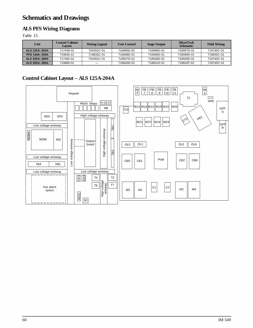
60 IM 549
Schematics and Drawings
Control Cabinet Layout – ALS 125A-204A
Keypad
Mech. relays F1 CB F2
NB
ADX EXV
Low voltage wireway
High voltage wireway
Mod
em
MDBI ADI
Low voltage wireway
Low voltage wireway
TB4 TB5
RE
S1
SC
GD
1
GD
2
T4
T8
T2
T7
Hig
h vo
ltag
ew
irew
ay
Low voltage wireway
Hig
h vo
ltag
e w
irew
ay
Low
vo
ltag
e w
irew
ay Outputboard
TB
3T
B2
FB11
FB10
FB9
FB8
FB7
FB6
T1
FB5
GRD
M11 M12 M13 M15 M23 M25T10
M21 M22 M14 M24 CT1 PB1
GFPS
GFPR
OL5 OL1 OL2 OL6
CB5 CB1 CB2PVM CB6
M5 M1C1 C2
M2 M6Fax alarm
option
ALS PFS Wiring DiagramsTable 15.
Unit Control Cabinet Wiring Legend Unit Control Stage Output MicroTech Field WiringLayout SchematicALS 125A-204A 717449-01 704352C-01 716995D-01 716996D-01 716997D-01 719740C-01PFS 140A-200A 719836-01 719833C-01 716998D-01 716999D-01 718099D-01 719835C-01ALS 205A-280A 717460-01 704352C-01 718507D-01 718508D-01 718509D-01 719740C-01ALS 300A-380A 719869-01 — 718640D-01 718641D-01 718642F-01 719740C-01

IM 549 61
Control Cabinet Layout – ALS 205A-280A
Low voltage wireway Low voltage wireway
Hig
h vo
ltage
wire
way
Hig
h vo
ltage
wire
way
Low voltage wireway High voltage wireway
High voltage wireway
Mod
emC31 SC31
C41 SC41
EXVB1 EXVB2
AOX04 DIOX18 DIC16
ADIMCB 280
Low voltage wireway
SC1
Res
1
SC2
Res
2
TB5TB4
Low
vol
tage
wire
way
OB2
TB6
Hig
h vo
ltage
wire
way
Mech. relays
Mech. relays
NB
F1 CB F2
TB2
TB3
T4
T8
T6
T2
T7
GDR1
GDR2
GDR3
GDR4
OBI
C1 M1 C3 M3 M2 C2 M4 C4
OL1
CB1
OL3
CB3
OL2
CB2
OL4
CB4
CT2
CT1
GRD
PB1
T1PVM1
FB5
FB17
FB16
FB15
FB14
FB13
FB12
M31
M41
M32
M42
M33
M35
M43
FB6
FB7
FB8
FB9
FB10
FB11
M34
M44
M45
M11
M12
M13
M15
M23
M25
M21
M22
T10
M14
M24

62 IM 549
Control Cabinet Layout – ALS 300A-380A
Low voltage wireway Low voltage wireway
Hig
h vo
ltage
wire
way
Hig
h vo
ltage
wire
way
Low voltage wireway High voltage wireway
High voltage wireway
Mod
em
EXVB1 EXVB2
AOX DIOX
ADIMCB 280
Low voltage wireway
SC2
Res
2
SC3
Res
3
TB5TB4
Low
vol
tage
wire
way
Keypad
TB6
Mech. relays
NB
F1 CB F2
TB2
TB3
T4
T8
T6
T2
T7
GDR1
GDR2
GDR3
GDR4
DBI
M1 M2 M3
DL1
CB1
DL2
CB2
DL3
CB3
CT2
GRD
PB1
T1
FB5
FB14
FB13
FB12
M31
M32
M33
M34
M35
FB6
FB7
FB8
FB9
FB10
FB11
M11
M12
M13
M15
M23
M25
M21
M22
T10
M14
M24
DB2
SC1
Res
1
CT1
CT3
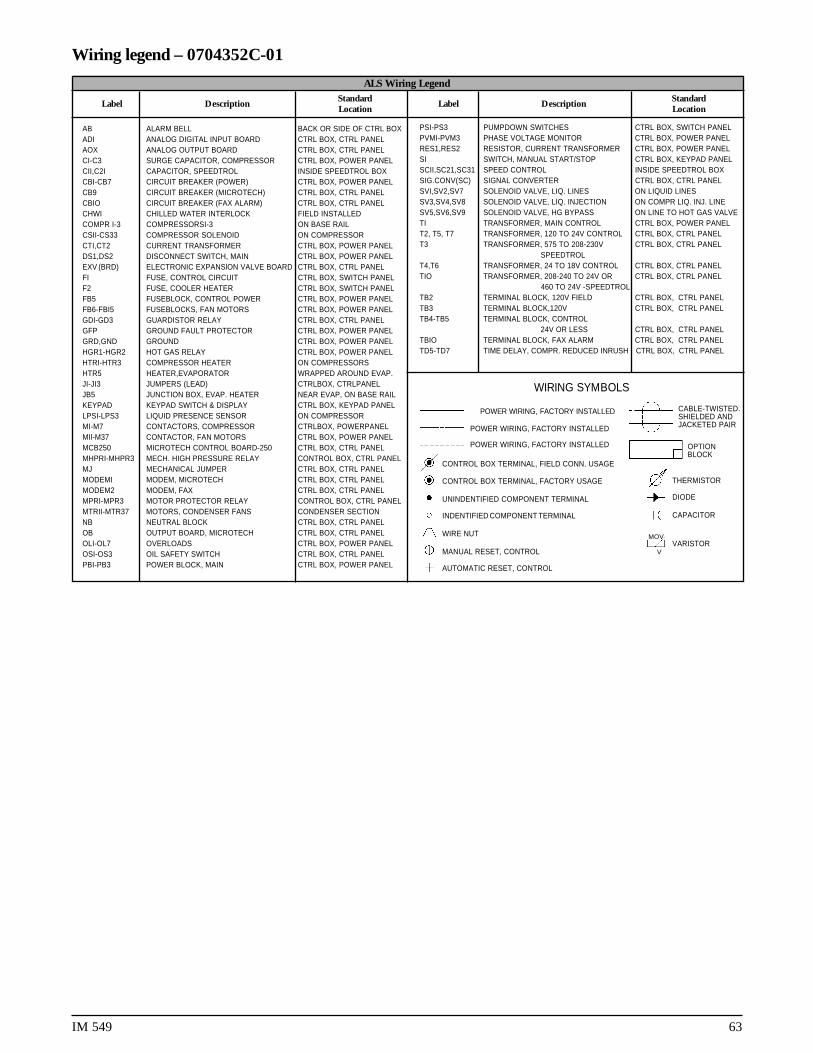
IM 549 63
Wiring legend – 0704352C-01
ALS Wiring Legend
Label DescriptionStandard
Label DescriptionStandard
Location Location
PSI-PS3 PUMPDOWN SWITCHES CTRL BOX, SWITCH PANELPVMI-PVM3 PHASE VOLTAGE MONITOR CTRL BOX, POWER PANELRES1,RES2 RESISTOR, CURRENT TRANSFORMER CTRL BOX, POWER PANELSI SWITCH, MANUAL START/STOP CTRL BOX, KEYPAD PANELSCII,SC21,SC31 SPEED CONTROL INSIDE SPEEDTROL BOXSIG.CONV(SC) SIGNAL CONVERTER CTRL BOX, CTRL PANELSVI,SV2,SV7 SOLENOID VALVE, LIQ. LINES ON LIQUID LINESSV3,SV4,SV8 SOLENOID VALVE, LIQ. INJECTION ON COMPR LIQ. INJ. LINESV5,SV6,SV9 SOLENOID VALVE, HG BYPASS ON LINE TO HOT GAS VALVETI TRANSFORMER, MAIN CONTROL CTRL BOX, POWER PANELT2, T5, T7 TRANSFORMER, 120 TO 24V CONTROL CTRL BOX, CTRL PANELT3 TRANSFORMER, 575 TO 208-230V CTRL BOX, CTRL PANEL
SPEEDTROLT4,T6 TRANSFORMER, 24 TO 18V CONTROL CTRL BOX, CTRL PANELTIO TRANSFORMER, 208-240 TO 24V OR CTRL BOX, CTRL PANEL
460 TO 24V -SPEEDTROLTB2 TERMINAL BLOCK, 120V FIELD CTRL BOX, CTRL PANELTB3 TERMINAL BLOCK,120V CTRL BOX, CTRL PANELTB4-TB5 TERMINAL BLOCK, CONTROL
24V OR LESS CTRL BOX, CTRL PANELTBIO TERMINAL BLOCK, FAX ALARM CTRL BOX, CTRL PANELTD5-TD7 TIME DELAY, COMPR. REDUCED INRUSH CTRL BOX, CTRL PANEL
WIRING SYMBOLS
POWER WIRING, FACTORY INSTALLED
POWER WIRING, FACTORY INSTALLED
POWER WIRING, FACTORY INSTALLED
CONTROL BOX TERMINAL, FIELD CONN. USAGE
CONTROL BOX TERMINAL, FACTORY USAGE
UNINDENTIFIED COMPONENT TERMINAL
INDENTIFIED COMPONENT TERMINAL
WIRE NUT
MANUAL RESET, CONTROL
AUTOMATIC RESET, CONTROL
MOV
V
OPTIONBLOCK
THERMISTOR
DIODE
CAPACITOR
VARISTOR
CABLE-TWISTED.SHIELDED ANDJACKETED PAIR
AB ALARM BELL BACK OR SIDE OF CTRL BOXADI ANALOG DIGITAL INPUT BOARD CTRL BOX, CTRL PANELAOX ANALOG OUTPUT BOARD CTRL BOX, CTRL PANELCI-C3 SURGE CAPACITOR, COMPRESSOR CTRL BOX, POWER PANELCII,C2I CAPACITOR, SPEEDTROL INSIDE SPEEDTROL BOXCBI-CB7 CIRCUIT BREAKER (POWER) CTRL BOX, POWER PANELCB9 CIRCUIT BREAKER (MICROTECH) CTRL BOX, CTRL PANELCBIO CIRCUIT BREAKER (FAX ALARM) CTRL BOX, CTRL PANELCHWI CHILLED WATER INTERLOCK FIELD INSTALLEDCOMPR I-3 COMPRESSORSI-3 ON BASE RAILCSII-CS33 COMPRESSOR SOLENOID ON COMPRESSORCTI,CT2 CURRENT TRANSFORMER CTRL BOX, POWER PANELDS1,DS2 DISCONNECT SWITCH, MAIN CTRL BOX, POWER PANELEXV (BRD) ELECTRONIC EXPANSlON VALVE BOARD CTRL BOX, CTRL PANELFI FUSE, CONTROL CIRCUIT CTRL BOX, SWITCH PANELF2 FUSE, COOLER HEATER CTRL BOX, SWITCH PANELFB5 FUSEBLOCK, CONTROL POWER CTRL BOX, POWER PANELFB6-FBI5 FUSEBLOCKS, FAN MOTORS CTRL BOX, POWER PANELGDI-GD3 GUARDISTOR RELAY CTRL BOX, CTRL PANELGFP GROUND FAULT PROTECTOR CTRL BOX, POWER PANELGRD,GND GROUND CTRL BOX, POWER PANELHGR1-HGR2 HOT GAS RELAY CTRL BOX, POWER PANELHTRI-HTR3 COMPRESSOR HEATER ON COMPRESSORSHTR5 HEATER,EVAPORATOR WRAPPED AROUND EVAP.JI-JI3 JUMPERS (LEAD) CTRLBOX, CTRLPANELJB5 JUNCTION BOX, EVAP. HEATER NEAR EVAP, ON BASE RAILKEYPAD KEYPAD SWITCH & DISPLAY CTRL BOX, KEYPAD PANELLPSI-LPS3 LIQUID PRESENCE SENSOR ON COMPRESSORMI-M7 CONTACTORS, COMPRESSOR CTRLBOX, POWERPANELMIl-M37 CONTACTOR, FAN MOTORS CTRL BOX, POWER PANELMCB250 MICROTECH CONTROL BOARD-250 CTRL BOX, CTRL PANELMHPRI-MHPR3 MECH. HIGH PRESSURE RELAY CONTROL BOX, CTRL PANELMJ MECHANICAL JUMPER CTRL BOX, CTRL PANELMODEMI MODEM, MICROTECH CTRL BOX, CTRL PANELMODEM2 MODEM, FAX CTRL BOX, CTRL PANELMPRI-MPR3 MOTOR PROTECTOR RELAY CONTROL BOX, CTRL PANELMTRII-MTR37 MOTORS, CONDENSER FANS CONDENSER SECTIONNB NEUTRAL BLOCK CTRL BOX, CTRL PANELOB OUTPUT BOARD, MICROTECH CTRL BOX, CTRL PANELOLI-OL7 OVERLOADS CTRL BOX, POWER PANELOSI-OS3 OIL SAFETY SWITCH CTRL BOX, CTRL PANELPBI-PB3 POWER BLOCK, MAIN CTRL BOX, POWER PANEL
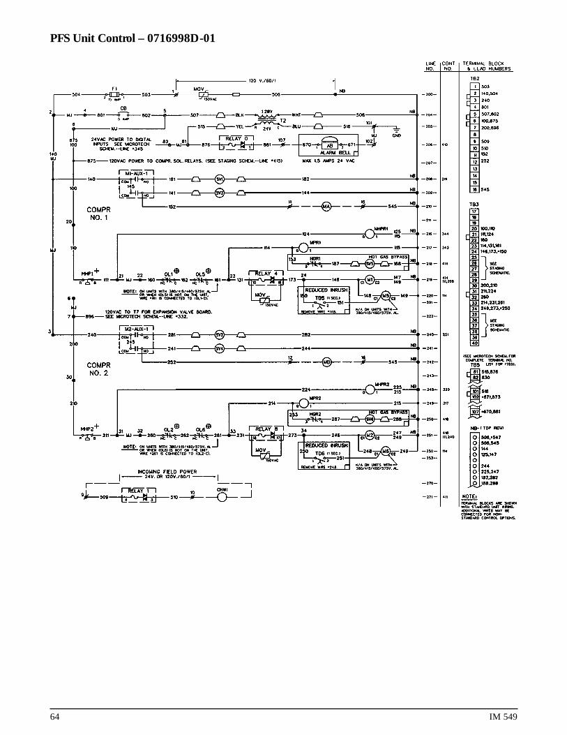
64 IM 549
PFS Unit Control – 0716998D-01

IM 549 65
PFS 8-Stage Output – 071699D-01

66 IM 549
PFS MicroTech – 717000D-01

IM 549 67
ALS Unit Control – 0716995D-01

68 IM 549
ALS 8-Stage Output – 0716996D-01

IM 549 69
ALS MicroTech – 2 Compressor Unit – 716997D-01

70 IM 549
ALS Field Wiring – 0719740C-01
Unit mainterminal block
Disconnect(by others) NB
TB2
63
62
61
–
+
+
–
–
+
–
107
102
60
55
54
53
52
51
50
49
48
47
46
45
10
9
16
13
1
TB5
TB4
N
120 VACcontrol power
10A fuse
(by others)
MJ
545If separate evaporator heaterpower option is used —remove wires 540 and 545.540
To compressor(s)and fan motors
Fused control circuittransformer option
Disconnect(by others) GND lug
3 phase
power
supply
Separateevaporator
heater poweroption
120 VAC(by others)
N
Disconnect(by others) 10A
fuse
(by others)
24V or 120 VAC(by others)
N
CHW pump relay(by others)
Output relay 1
Output relay 0
5A
GND
24 VAC-35 VA max.
Alarm bellmax 1.5 amps
Alarm belloption
Factory suppliedalarm field wired
CHW flow switch(by others)
Remote stop(by others)
Timeclock
Off
Auto
Manual
If remote stop controlis used, remove jumperfrom terminals 60 to 61.
5-GND
4-CLR (RS485)
3-BLK (RS485)
5-GND
1-CLR (RS232 TR)
3-BLK (RS232 RC) Communicationport “A”
Communicationport “B”
GND
GND
GND
250 Ω loadimpedance
250 Ω loadimpedance
Inherent inMicroTechcontroller
Connection to RMS(remote monitoring sequence)
or to NMP(network master panel)
Connection to RS232for modem or direct
PC connection
4-20 MA forCHW reset(by others)
4-20 MA fordemand limit(by others)
5A
Solid state relay24V or 120 VAC1.5 amps max.
+
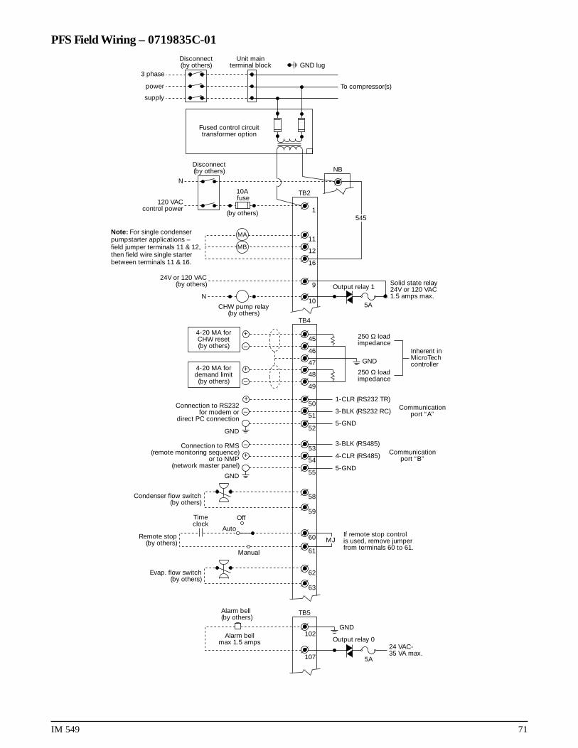
IM 549 71
PFS Field Wiring – 0719835C-01Unit main
terminal block
Disconnect(by others) NB
TB2
63
62
61
–
+
+
–
–
+
–
107
102
60
55
54
53
52
51
50
49
48
47
46
45
10
9
16
12
1
TB5
TB4
N
120 VACcontrol power
10A fuse
(by others)
MJ
545
To compressor(s)
Fused control circuittransformer option
Disconnect(by others) GND lug
3 phase
power
supply
Note: For single condenserpumpstarter applications –field jumper terminals 11 & 12,then field wire single starterbetween terminals 11 & 16.
24V or 120 VAC(by others)
N
CHW pump relay(by others)
Output relay 1
Output relay 0
5A
GND
24 VAC-35 VA max.
Alarm bellmax 1.5 amps
Alarm bell(by others)
Evap. flow switch(by others)
Remote stop(by others)
Timeclock
Off
Auto
Manual
If remote stop controlis used, remove jumperfrom terminals 60 to 61.
5-GND
4-CLR (RS485)
3-BLK (RS485)
5-GND
1-CLR (RS232 TR)
3-BLK (RS232 RC) Communicationport “A”
Communicationport “B”
GND
GND
GND
250 Ω loadimpedance
250 Ω loadimpedance
Inherent inMicroTechcontroller
Connection to RMS(remote monitoring sequence)
or to NMP(network master panel)
Connection to RS232for modem or
direct PC connection
4-20 MA forCHW reset(by others)
4-20 MA fordemand limit(by others)
5A
Solid state relay24V or 120 VAC1.5 amps max.
+
59
58Condenser flow switch(by others)
11MB
MA

13600 Industrial Park Boulevard, P.O. Box 1551, Minneapolis, MN 55440 USA (612) 553-5330
®