packaged terminal air conditioner & heat pumps
TRANSCRIPT

Packaged Terminal AirConditioners & Heat Pumps
PTAC-PRC001-ENOctober 2000

©American Standard Inc. 2000 PTAC-PRC001-EN
Introduction
The new Trane packaged terminal air conditioners (PTACs) and heat pumps are ideally suited for offices, apartments, hotels,motels and institutional homes. Key benefits which make the units a wise choice are:
• Energy efficiency• Reliability• Quiet operation• Comfort• Easy-to-use controls• Attractive and compact design• Ease of installation and servicing

3
Contents
PTAC-PRC001-EN
Introduction
Features and Benefits
Application Considerations
Selection Procedure
Model Number Description
Performance Data
Cool and Heat Performance
Electric Power
Power Connection Wiring
Dimension and Weights
Mechanical Specifications
OptionsWarranty
2
4
6
7
78
815
1516
20
2224

PTAC-PRC001-EN4
Features andBenefits
Energy EfficiencyTrane PTAC units and heat pumps areamong the most efficient in the industry,with EERs of up to 11.6 and COPs of upto 3.3. The efficient design of the PSCmotor and airflow pattern help to reducethe energy consumption of the fan.Packaged terminal heat pumps tend tobe more efficient than electric heat only.In fact, operating savings may result in apayback of less than one year. Duringheating operation, refrigerant in the heatpump runs in the reverse direction of thecooling operation. The outside air iscooled, thereby giving up heat to therefrigerant in the heat pump.This heat is then pumped back inside,resulting in up to three Btu’s of heat forevery Btu of energy consumed.During cooling operation, heat isremoved from the building as the air iscooled. This heat proceeds through thecompression cycle and is ultimatelyrejected to the outside air.Energy-saving options available withPTAC units include:
Front Desk Contact Point
Each unit has low voltage interfacecapability with a field-supplied ON/OFFswitch. Turn off heating or cooling tounoccupied rooms.
Fan Mode Switch
Select continuous fan operation or cyclethe fan ON and OFF with the compressoror heat operation. The switch isconcealed to help prevent tampering byunauthorized personnel.
Temperature Limiter
This unit-mounted mechanical controlallows guests to adjust in-roomtemperature settings within a pre-programmed range.
Reliability
These features help assure reliableoperation:
Freeze Protection
When the unit senses temperatures of40°F or below, the unit activates the fanmotor and either the electric resistanceheater or the hydronic heater to helpprevent pipes or fixtures from freezing.This also overrides front desk control ofthe unit mounted or wall sensor.
Automatic Emergency Heat
Each unit automatically switches over toelectric resistance heat if for any reasonthe heat pump compressor system failsor if the heating load is greater than theunit capacity.
Random Restart
Avoid troublesome power surges thatcan damage electrical circuits. Each unithas a random restart circuit to prevent allunits from restarting at one time afterpower disruption.
Compressor Restart Delay
Extend compressor life. The unitautomatically delays any restart attemptby three minutes to allow the refrigerantpressures time to equalize.
Quiet Operation
State-of-the-art design and constructionprovide a quiet environment for gueststo relax. Contributing to the quietoperation of the unit are:•An acoustically insulated bulkhead.•Acoustical rubber-in-shear isolators
under the compressor.•An isolated fan motor.
Operating sound levels are furtherdampened when the unit is in the LOWFAN mode of operation.
ComfortDehumidification and air filtration areboth factors affecting comfort. When theair is dehumidified, occupants feel morecomfortable at higher temperatures.Trane PTACs help maintain lowerhumidity levels in rooms, without theneed for expensive add-on’s. Anotherbenefit is that dehumidification can helpextend the life of furniture, wallcoverings and fixtures.When ventilation air is filtered, roomsstay cleaner, longer. The hiddenventilation air intake filters outside air toreduce dust and pollen.
User-Friendly Controls
Controls are easy to read, understandand activate.

5PTAC-PRC001-EN
Features andBenefits
When the filter needs to be cleaned orreplaced, the filter access door tiltsforward for easy access. For moreextensive service, the unit slides out ofthe sleeve easily for full access to allworking components.
Remote Thermostat Control
Each unit is built to be operated from aremote-mounted thermostat, if desired.Even if it is started without a remote, abuilt-in low voltage power source canaccommodate a large variety ofthermostat choices — manual, autochangeover or programmable — at alater date.
Remote Temperature SensingOccupants enjoy ultimate comfort withconsistent climate control. Attach anoptional, inexpensive remote thermistortemperature sensing device andtemperatures are held more closely tothe chosen room setting.
Attractive and Compact DesignThe unit front has a sleek seven-inchdepth, one of the shallowest silhouettesin the industry today. To inhibittampering, the front can be secured tothe chassis with hidden screws.Our unit’s new stylish design and neutralcolor make it compatible with virtuallyany room decor or architectural design. Itblends into the room’s color scheme.
Special Paint ProtectionThe electrodeposition paint system onthe exterior panels assure the unit andwall sleeve will withstand years ofmoisture and atmospheric pollutantswithout giving up its looks to rust andcorrosion.
Ease of Installation and ServicingAfter the sleeve is in place, plug in ordirectly hard-wire the unit and it is readyto run. This unit has been designed toreplace most competitors’ units. In factthis unit can fit into most existingsleeves, making replacement of old orinefficient units easy and economical.And of course, the units may be installedflush with the outside wall.The main components are easilyserviced; the unit is easy to diagnose ortroubleshoot to spot potential problems.

PTAC-PRC001-EN6
ApplicationConsiderations
Curtain Wall Installation Block and Brick Veneer Installation Frame and Brick Veneer Installation
Optional Leveling LegPanel Wall Installation Panel Wall and Block Veneer Installation
On applications not requiring subbase or leveling legs, unit may be flush mounted to floor.
Sleeve Installation Data
Framing for Wall Case Framing With Lintel Attaching Wall Sleeve to Opening
1. 3¼” minimum with subbase.2. On applications not requiring subbase or
leveling legs, unit may be flush mounted to floor.

7PTAC-PRC001-EN
ModelNumberDescription
Digits 1,2 — Packaged Terminal
Air Conditioner
Digit 3 — Product Type
E = Air ConditionerH = Heat Pump
Digit 4 — Development Sequence
C = Third Development
Digits 5,6,7 — Unit Cooling Capacity
070 = 7,000 Btu090 = 9,000 Btu120 = 12,000 Btu150 = 15,000 Btu
Digit 8 — Main Power Supply
1 = 208-230/60/12 = 265/60/1
Digit 9 — Electric Heating Capacity**
0 = No Electric Heat – Air Conditioners OnlyE = 2.5 kWG = 3.5 kW (208-230V)G = 3.7 kW (265V)J = 5.0 kW*
Digit 10 — Design Sequence
Digit 11— Miscellaneous
A = StandardB = Power VentC = Corrosion ResistantD = Condensate PumpH = Hydronic ChassisF = Hydronic with Power Vent and DoorG = Hydronic with Power DoorJ = Power DoorK = Condensate Pump with Power VentL = Condensate Pump with Power Door
Stock Style Models
PTEC0701GCAPTEC0901GCAPTEC1201GCA
PTEC1501GCAPTEC1501JCA
PTHC0701GCAPTHC0901GCAPTHC1201GCA
MODEL NOMENCLATURE
PT E C 090 1 G * A
Notes:1. Corrosion resistant, condensate pump, power vent units and all special units require extended ship cycles.2. Only the following units are available from stock and can normally ship within 3 days after release.3. Contact your local Trane representative for current stock availability and information on minimum quantityrequirements and shipping schedule for special production units.
PTHC1501GCAPTHC1501JCA
PTEC0902GCAPTHC0902GCAPTEC1202GCAPTHC1202GCAPTEC1502GCAPTHC1502GCA*Sizes 09, 12 and 15 only.**All heat pump units must have electric coils.

PTAC-PRC001-EN8
Table PD-1 — Cooling Performance — Air Conditioner with Electric Heat Models
Model Type Air ConditionerModel No.1 & 5 PTEC 07 PTEC 09 PTEC 12 PTEC 15Voltage3 208 230 265 208 230 265 208 230 265 208 230 265Capacity (Btu)6 7000 7100 7100 8900 9100 9100 11900 12000 12000 14000 14200 14200Amps 3.0 2.8 2.3 3.8 3.7 3.0 5.0 5.0 4.3 6.9 6.9 5.9Watts 600 610 610 785 805 805 1110 1110 1130 1520 1545 1525EER 11.6 11.6 11.6 11.3 11.3 11.3 10.7 10.7 10.7 9.2 9.2 9.3Unit without Electric HeaterMin. Circuit/Ampacity 2 & 4 4.0 4.0 3.6 5.1 5.1 4.4 6.4 6.4 6.4 8.4 8.4 7.4cfm (cool, wet coil)
High 240 245 245 240 245 245 325 315 325 315 325 325Low 205 220 220 205 220 220 250 220 250 220 250 250
cfm (dry coil)High 260 265 265 260 265 265 345 335 345 335 345 345Low 215 230 230 215 230 230 265 235 265 235 265 265
Ventilated Air, cfm (fan only) 65* 65* 65* 65* 65* 65* 70* 70* 70* 70* 70* 70*Dehumidification (pints/hr.) 1.6 1.6 1.6 2.6 2.6 2.6 3.5 3.5 3.5 4.4 4.4 4.4Net wt. (approximate lbs.) 90 90 90 95 95 95 105 105 105 110 110 110Shipping wt. (approximate lbs.) 105 105 105 110 110 110 120 120 120 125 125 125* 95 cfm with optional power vent kit. Actual vent cfm performance will vary due to application and installation conditions.
Table PD-2 — Cooling Performance —Heat Pump with Electric Heat Models
Model Type Heat PumpsModel No.1 & 5 PTHC 07 PTHC 09 PTHC 12 PTHC 15Voltage3 208 230 265 208 230 265 208 230 265 208 230 265Capacity(Btu)6 7000 7100 7100 8800 9000 9000 11800 12000 12000 13800 14000 14000Amps 3.0 2.8 2.3 3.8 3.5 3.0 5.0 4.6 4.3 6.9 6.3 5.9Watts 610 615 615 785 805 805 1110 1120 1120 1485 1505 1505EER 11.5 11.5 11.5 11.2 11.2 11.2 10.7 10.7 10.7 9.3 9.3 9.3Unit without Electric HeaterMin Circuit/Ampacity 2 & 4 4.0 4.0 3.6 5.1 5.1 4.4 7.3 7.3 5.7 8.4 8.4 7.4cfm (cool, wet coil)
High 240 245 245 240 245 245 315 325 325 315 325 325Low 205 220 220 205 220 220 220 250 250 220 250 250
cfm (dry coil)High 260 265 265 260 265 265 335 345 345 335 345 345Low 215 230 230 215 230 230 235 265 265 235 265 265
Ventilated Air, cfm (fan only) 65* 65* 65* 65* 65* 65* 70* 70* 70* 70* 70* 70*Dehumidification (pints/hr.) 1.6 1.6 1.6 2.6 2.6 2.6 3.5 3.5 3.5 4.4 4.4 4.4Net wt. (approximate lbs.) 95 95 95 100 100 100 110 110 110 115 115 115Shipping wt. (approximate lbs.) 110 110 110 115 115 115 125 125 125 130 130 130*95 cfm with optional power vent kit. Actual vent cfm performance will vary due to application and installation conditions.
Notes:1. All 265 volt models must use Trane’s subbase or Trane’s hard-wire junction box kit.2. Minimum branch circuit ampacity ratings conform to the National Electric Code. However, local codes should apply.3. Minimum voltage on 208/230 volt models is 197 volts; maximum is 253 volts. Minimum voltage on 265 volt models is 238.5 volts; maximum is 291.5 volts.4. Overcurrent protection for all units without electric heaters is 15 amps. Overcurrent protection on 265 volt models must be cartridge-style time delay fuses (included and
factory installed on Trane chassis). Note: All heat pump units must have electric coils.5. Minimum operating ambient = 45°F.6. Certified in accordance with the Unitary Air-Conditioner Equipment certification program, which is based on ARI standard 310/380.
EER — Energy Efficiency Ratio per American Refrigeration Institute (ARI) Test Procedures.COP — Coefficient of Performance per ARI Test Procedures.
PerformanceData

9PTAC-PRC001-EN
PerformanceData
Table PD-3 — Heat Pump Reverse Cycle Heating Capacity (Btu)
Model No.1 PTHC 07 PTHC 09 PTHC 12 PTHC 15Voltage3 208 230 265 208 230 265 208 230 265 208 230 265Amps 3.0 2.6 2.2 3.6 3.2 2.6 5.1 4.5 3.9 6.3 5.7 5.4Watts 550 570 570 730 740 740 1000 1020 1020 1380 1390 1390Btu2 6200 6400 6400 8000 8100 8100 10600 10800 10800 13500 13300 13300COP2 3.3 3.3 3.3 3.2 3.2 3.2 3.1 3.1 3.1 2.8 2.8 2.8cfm (dry) 230 235 235 230 235 235 290 310 310 335 345 345Heating2 Btu °FOutdoor Ambient 62 8200 8400 8400 10200 10300 10300 13000 13200 13200 16300 16400 16400
57 7600 7800 7800 9600 9700 9700 12200 12400 12400 15300 15400 1540052 6900 7100 7100 8900 9000 9000 11400 11600 11600 14200 14300 1430047 6200 6400 6400 8000 8100 8100 10600 10800 10800 13200 13300 13300
Rating Point (COP) 3.3 3.3 3.3 3.2 3.2 3.2 3.1 3.1 3.1 2.8 2.8 2.82 42 5500 5700 5700 7200 7300 7300 9800 10000 10000 12200 12300 12300
37 4900 5100 5100 6400 6500 6500 9000 9200 9200 11200 11300 1130032 4300 4500 4500 5600 5700 5700 8200 8400 8400 10100 10200 10200
Watts 62 730 745 745 935 940 940 1230 1245 1245 1705 1715 1715Outdoor Ambient 57 675 690 690 880 890 890 1150 1170 1170 1600 1610 1610
52 610 630 630 815 825 825 1075 1095 1095 1485 1495 149547 550 570 570 730 740 740 1000 1020 1020 1380 1390 139042 490 505 505 660 670 670 925 945 945 1275 1285 128537 435 450 450 585 595 595 850 870 870 1170 1180 118032 380 400 400 510 520 520 775 795 795 1055 1065 1065
Notes:1. All 265 volt models must use Trane’s subbase or Trane’s hard-wire junction box kit.2. Heating capacity and efficiency is based on unit operation without condensate pump. Unit automatically switches to electric heat at 25°F outdoor coil temperature.
Depending upon relative humidity conditions, this will occur at approximately 35 degrees outdoor ambient temperature.

PTAC-PRC001-EN10
PerformanceData
Table PD-4 — PTEC Air Conditioner — 208V
WBT Ent DBT Ent Outdoor Temperature (°F)Nominal Indoor Indoor 85 95 105 115
Unit Coil Coil Total Sen % Total Sen % Total Sen % Total Sen %Size (°F) (°F) Btu Btu SH Btu Btu SH Btu Btu SH Btu Btu SH
75 6680 5695 85 6380 5545 87 6030 5665 94 5710 5530 9761 80 6930 6930 100 6665 6665 100 6270 6270 100 5980 5980 100
85 7205 7205 100 7030 7030 100 6745 6745 100 6320 6320 10075 7440 4005 54 7155 4140 58 6680 4150 62 6290 4000 64
07 67 80 7345 5385 73 *7000 5250 75 6660 5295 80 6270 5175 8385 7390 6570 89 7105 6445 91 6690 6270 94 6330 6330 10075 8335 2835 34 7885 2800 36 7485 2665 36 7070 2520 36
73 80 8245 3980 48 7875 3850 49 7415 3845 52 7010 3710 5385 8150 5285 65 7750 4995 64 7345 4845 66 6940 4705 6875 8385 6285 75 7940 6065 76 7460 5830 78 6960 5600 80
61 80 8335 7390 89 7905 7165 91 7435 6930 93 7050 7050 10085 8480 8480 100 8130 8130 100 7765 7765 100 7345 7345 10075 9510 5010 53 9075 4810 53 8465 4610 54 7900 4510 57
09 67 80 9410 6240 66 *8900 5820 65 8355 5610 67 7795 5335 6885 9255 7295 79 8825 7165 81 8210 6890 84 7680 6470 8475 10710 3705 35 10135 3490 34 9555 3280 34 8935 3060 34
73 80 10585 4790 45 10020 4580 46 9420 4365 46 8795 4145 4785 10450 5875 56 9880 5665 57 9270 5445 59 8640 5230 6175 11265 8715 77 10610 8410 79 9875 8070 82 9000 7675 85
61 80 11220 10210 91 10575 9890 94 9815 9525 97 9110 9110 10085 11505 11505 100 10965 10965 100 10300 10300 100 9605 9605 10075 12770 6910 54 12205 6670 55 11320 6305 56 10440 5950 57
12 67 80 12630 8330 66 *11900 8025 67 11115 7705 69 10200 7370 7285 12425 9815 79 11805 9560 81 10905 9215 85 9980 8875 8975 14435 5060 35 13645 4765 35 12840 4470 35 11925 4145 35
73 80 14260 6520 46 13460 6230 46 12640 5930 47 11630 5575 4885 14070 7985 57 13290 7700 58 12370 7400 60 11350 7020 6275 13245 10205 77 12490 9830 79 11570 9405 81 10610 8940 84
61 80 13140 11930 91 12345 11515 93 11395 11045 97 10760 10760 10085 13465 13465 100 12775 12775 100 11965 11965 100 11325 11325 10075 15035 8120 54 14365 7835 55 13280 7345 55 12200 6875 56
15 67 80 14845 9745 66 *14000 9375 67 13020 8975 69 11990 8575 7285 14575 11455 79 13785 11125 81 12670 10680 84 11790 10370 8875 16875 5915 35 16120 5625 35 15130 5260 35 14010 4790 34
73 80 16780 7655 46 15870 7315 46 14835 6905 47 13635 6445 4785 16535 9330 56 15595 8970 58 14530 8610 59 13385 8225 61
*These capacities are based on ARI rating point 80/67 entering air temperature, 95°F outdoor ambient.

11PTAC-PRC001-EN
PerformanceData
Table PD-5 — PTEC Air Conditioner — 230/265V
WBT Ent DBT Ent Outdoor Temperature (°F)Nominal Indoor Indoor 85 95 105 115
Unit Coil Coil Total Sen % Total Sen % Total Sen % Total Sen %Size (°F) (°F) Btu Btu SH Btu Btu SH Btu Btu SH Btu Btu SH
75 6780 5795 85 6480 5645 87 6130 5765 94 5810 5630 9761 80 7030 7030 100 6765 6765 100 6370 6370 100 6080 6080 100
85 7305 7305 100 7130 7130 100 6845 6845 100 6420 6420 10075 7540 4105 54 7255 4240 58 6780 4250 63 6390 4100 64
07 67 80 7445 5485 74 *7100 5350 75 6760 5395 80 6370 5275 8385 7490 6670 89 7205 6545 91 6790 6370 94 6430 6430 10075 8435 2935 35 7985 2900 36 7585 2765 36 7170 2620 37
73 80 8345 4080 49 7975 3950 50 7515 3945 52 7110 3810 5485 8250 5385 65 7850 5095 65 7445 4945 66 7040 4805 6875 8585 6485 76 8140 6265 77 7660 6030 79 7160 5800 81
61 80 8535 7590 89 8105 7365 91 7635 7130 93 7250 7250 10085 8680 8680 100 8330 8330 100 7965 7965 100 7545 7545 10075 9710 5210 54 9275 5010 54 8665 4810 56 8100 4710 58
09 67 80 9610 6440 67 *9100 6020 66 8555 5810 68 7995 5535 6985 9455 7495 79 9025 7365 82 8410 7090 84 7880 6670 8575 10910 3905 36 10335 3690 36 9755 3480 36 9135 3260 36
73 80 10785 4990 46 10220 4780 47 9620 4565 47 8995 4345 4885 10650 6075 57 10080 5865 58 9470 5645 60 8840 5430 6175 11365 8815 78 10710 8510 79 9975 8170 82 9100 7775 85
61 80 11320 10310 91 10675 9990 94 9915 9625 97 9210 9210 10085 11605 11605 100 11065 11065 100 10400 10400 100 9705 9705 10075 12870 7010 54 12305 6770 55 11420 6405 56 10540 6050 57
12 67 80 12730 8430 66 *12000 8125 68 11215 7805 70 10300 7470 7385 12525 9915 79 11905 9660 81 11005 9315 85 10080 8975 8975 14535 5160 36 13745 4865 35 12940 4570 35 12025 4245 35
73 80 14360 6620 46 13560 6330 47 12740 6030 47 11730 5675 4885 14170 8085 57 13390 7800 58 12470 7500 60 11450 7120 6275 13445 10405 77 12690 10030 79 11770 9605 82 10810 9140 85
61 80 13340 12130 91 12545 11715 93 11595 11245 97 10960 10960 10085 13665 13665 100 12975 12975 100 12165 12165 100 11525 11525 10075 15235 8320 55 14565 8035 55 13480 7545 56 12400 7075 57
15 67 80 15045 9945 66 *14200 9575 67 13220 9175 69 12190 8775 7285 14775 11655 79 13985 11325 81 12870 10880 85 11990 10570 8875 17075 6115 36 16320 5825 36 15330 5460 36 14210 4990 35
73 80 16980 7855 46 16070 7515 47 15035 7105 47 13835 6645 4885 16735 9530 57 15795 9170 58 14730 8810 60 13585 8425 62
*These capacities are based on ARI rating point 80/67 entering air temperature, 95°F outdoor ambient.
PTAC-PRC001-EN12
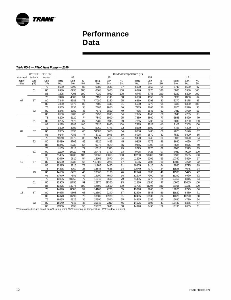
Table PD-6 — PTHC Heat Pump — 208V
WBT Ent DBT Ent Outdoor Temperature (°F)Nominal Indoor Indoor 85 95 105 115
Unit Coil Coil Total Sen % Total Sen % Total Sen % Total Sen %Size (°F) (°F) Btu Btu SH Btu Btu SH Btu Btu SH Btu Btu SH
75 6680 5695 85 6380 5545 87 6030 5665 94 5710 5530 9761 80 6930 6930 100 6665 6665 100 6270 6270 100 5980 5980 100
85 7205 7205 100 7030 7030 100 6745 6745 100 6320 6320 10075 7440 4005 54 7155 4140 58 6680 4150 62 6290 4000 64
07 67 80 7345 5385 73 *7000 5250 75 6660 5295 80 6270 5175 8385 7390 6570 89 7105 6445 91 6690 6270 94 6330 6330 10075 8335 2835 34 7885 2800 36 7485 2665 36 7070 2520 36
73 80 8245 3980 48 7875 3850 49 7415 3845 52 7010 3710 5385 8150 5285 65 7750 4995 64 7345 4845 66 6940 4705 6875 8290 6120 74 7840 5900 75 7350 5660 77 6855 5420 79
61 80 8225 7175 87 7785 6945 89 7315 6705 92 6810 6790 10085 8285 8285 100 7920 7920 100 7525 7525 100 7105 7105 10075 9420 4905 52 8960 4775 53 8360 4500 54 7785 4400 57
09 67 80 9305 5890 63 *8800 5660 64 8250 5485 66 7675 5170 6785 9145 7085 77 8710 6945 80 8095 6670 82 7520 6400 8575 10610 3675 35 10050 3465 34 9450 3245 34 8835 3020 34
73 80 10480 4705 45 9920 4495 45 9315 4275 46 8690 4050 4785 10345 5730 55 9775 5520 56 9165 5300 58 8535 5075 5975 11165 8615 77 10510 8310 79 9775 7970 82 8900 7575 85
61 80 11120 10110 91 10475 9790 93 9715 9425 97 9010 9010 10085 11405 11405 100 10865 10865 100 10200 10200 100 9505 9505 10075 12670 6810 54 12105 6570 54 11220 6205 55 10340 5850 57
12 67 80 12530 8230 66 *11800 7925 67 11015 7605 69 10100 7270 7285 12325 9715 79 11705 9460 81 10805 9115 84 9880 8775 8975 14335 4960 35 13545 4665 34 12740 4370 34 11825 4045 34
73 80 14160 6420 45 13360 6130 46 12540 5830 46 11530 5475 4785 13970 7885 56 13190 7600 58 12270 7300 59 11250 6920 6275 13055 10055 77 12310 9690 79 11405 9270 81 10460 8815 84
61 80 12955 11755 91 12170 11350 93 11230 10885 97 10605 10605 10085 13275 13275 100 12590 12590 100 11795 11795 100 11165 11165 10075 14820 8000 54 14160 7720 55 13090 7240 55 12025 6775 56
15 67 80 14635 9605 66 *13800 9240 67 12830 8845 69 11820 8450 7185 14370 11290 79 13585 10970 81 12485 10530 84 11620 10220 8875 16635 5825 35 15890 5540 35 14915 5185 35 13810 4720 34
73 80 16540 7545 46 15645 7210 46 14625 6805 47 13440 6355 4785 16300 9195 56 15370 8845 58 14320 8490 59 13195 8105 61
*These capacities are based on ARI rating point 80/67 entering air temperature, 95°F outdoor ambient.
PerformanceData

13PTAC-PRC001-EN
PerformanceData
Table PD-7 — PTHC Heat Pump — 230/265V
WBT Ent DBT Ent Outdoor Temperature (°F)Nominal Indoor Indoor 85 95 105 115
Unit Coil Coil Total Sen % Total Sen % Total Sen % Total Sen %Size (°F) (°F) Btu Btu SH Btu Btu SH Btu Btu SH Btu Btu SH
75 6780 5795 85 6480 5645 87 6130 5765 94 5810 5630 9761 80 7030 7030 100 6765 6765 100 6370 6370 100 6080 6080 100
85 7305 7305 100 7130 7130 100 6845 6845 100 6420 6420 10075 7540 4105 54 7255 4240 58 6780 4250 63 6390 4100 64
07 67 80 7445 5485 74 *7100 5350 75 6760 5395 80 6370 5275 8385 7490 6670 89 7205 6545 91 6790 6370 94 6430 6430 10075 8435 2935 35 7985 2900 36 7585 2765 36 7170 2620 37
73 80 8345 4080 49 7975 3950 50 7515 3945 52 7110 3810 5485 8250 5385 65 7850 5095 65 7445 4945 66 7040 4805 6875 8490 6320 74 8040 6100 76 7550 5860 78 7055 5620 80
61 80 8425 7375 88 7985 7145 89 7515 6905 92 7010 6990 10085 8485 8485 100 8120 8120 100 7725 7725 100 7305 7305 10075 9620 5105 53 9160 4975 54 8560 4700 55 7985 4600 58
09 67 80 9505 6090 64 *9000 5860 65 8450 5685 67 7875 5370 6885 9345 7285 78 8910 7145 80 8295 6870 83 7720 6600 8575 10810 3875 36 10250 3665 36 9650 3445 36 9035 3220 36
73 80 10680 4905 46 10120 4695 46 9515 4475 47 8890 4250 4885 10545 5930 56 9975 5720 57 9365 5500 59 8735 5275 6075 11365 8815 78 10710 8510 79 9975 8170 82 9100 7775 85
61 80 11320 10310 91 10675 9990 94 9915 9625 97 9210 9210 10085 11605 11605 100 11065 11065 100 10400 10400 100 9705 9705 10075 12870 7010 54 12305 6770 55 11420 6405 56 10540 6050 57
12 67 80 12730 8430 66 *12000 8125 68 11215 7805 70 10300 7470 7385 12525 9915 79 11905 9660 81 11005 9315 85 10080 8975 8975 14535 5160 36 13745 4865 35 12940 4570 35 12025 4245 35
73 80 14360 6620 46 13560 6330 47 12740 6030 47 11730 5675 4885 14170 8085 57 13390 7800 58 12470 7500 60 11450 7120 6275 13255 10255 77 12510 9890 79 11605 9470 82 10660 9015 85
61 80 13155 11955 91 12370 11550 93 11430 11085 97 10805 10805 10085 13475 13475 100 12790 12790 100 11995 11995 100 11365 11365 10075 15020 8200 55 14360 7920 55 13290 7440 56 12225 6975 57
15 67 80 14835 9805 66 *14000 9440 67 13030 9045 69 12020 8650 7285 14570 11490 79 13785 11170 81 12685 10730 85 11820 10420 8875 16835 6025 36 16090 5740 36 15115 5385 36 14010 4920 35
73 80 16740 7745 46 15845 7410 47 14825 7005 47 13640 6555 4885 16500 9395 57 15570 9045 58 14520 8690 60 13395 8305 62
*These capacities are based on ARI rating point 80/67 entering air temperature, 95°F outdoor ambient.

PTAC-PRC001-EN14
PerformanceData
Table PD-8 — Heating Capacity — Water
Heating Capacity (Btu) Hot WaterPressure 7000 & 9000 Btu Units 12000 Btu Units 15000 Btu Units
Drop(psig) 200°F EWT 180°F EWT 200°F EWT 180°F EWT 200°F EWT 180°F EWT
2-Way Fan Speed Fan Speed Fan Speed Fan Speed Fan Speed Fan Speedgpm Coil Valve Hi Lo Hi Lo Hi Lo Hi Lo Hi Lo Hi Lo1.00 0.93 0.19 14910 13388 12639 11186 16945 14387 14257 12152 17858 15534 15049 133121.13 1.03 0.24 15216 13706 12898 11452 17360 14689 14607 12407 18276 15955 15401 136721.25 1.14 0.30 15500 13997 13139 11696 17745 14968 14930 12642 18666 16338 15729 140011.38 1.26 0.36 15762 14262 13361 11917 18099 15222 15228 12858 19025 16684 16032 142971.50 1.40 0.43 16003 14501 13565 12117 18423 15454 15501 13053 19356 16991 16311 145611.63 1.55 0.50 *16222 14714 13751 12295 18717 15661 15748 13228 19658 17261 16565 147921.75 1.71 0.58 16420 14900 13919 12450 18980 15845 15969 13384 19930 17494 16794 149911.88 1.89 0.66 16596 15061 14068 12584 19212 16006 16165 13519 20173 17689 16999 151582.00 2.10 0.76 16751 15195 14199 12696 *19268 16142 16212 13635 20387 17846 17179 152932.13 2.32 0.85 16884 15302 14312 12786 19586 16255 16479 13730 *20445 17965 17229 153952.25 2.57 0.96 16995 15384 14407 12854 19727 16345 16598 13806 20727 18047 17466 154652.38 2.84 1.07 17085 15439 14483 12900 19838 16410 16691 13861 20853 18091 17572 155032.50 3.14 1.18 17154 15467 14541 12924 19919 16452 16759 13897 20950 18097 17654 155082.63 3.48 1.30 17201 15470 14581 12926 19968 16471 16801 13912 21018 18065 17711 154812.75 3.85 1.43 17226 15505 14603 12956 19988 16580 16817 14004 21056 18140 17744 15545
*Based on ARI Rating Conditions of 70°F Entering Air Temp., 200°F Entering Water Temp and 180°F Leaving Water Temp.Max Water Temperature 200°F Max. Water Pressure - 200 psig.
Table PD-9 — Heating Capacity — Steam
7,000 & 9,000 Btu Units 12,000 Btu Units 15,000 Btu Units
Steam Fan Speed Fan Speed Fan SpeedPSIG High Low High Low High Low
2 20,236 17,816 21,694 18,306 23,709 —3 20,686 18,253 22,100 19,003 25,676 21,0994 20,821 18,544 22,822 19,313 26,325 23,678
15PTAC-PRC001-EN
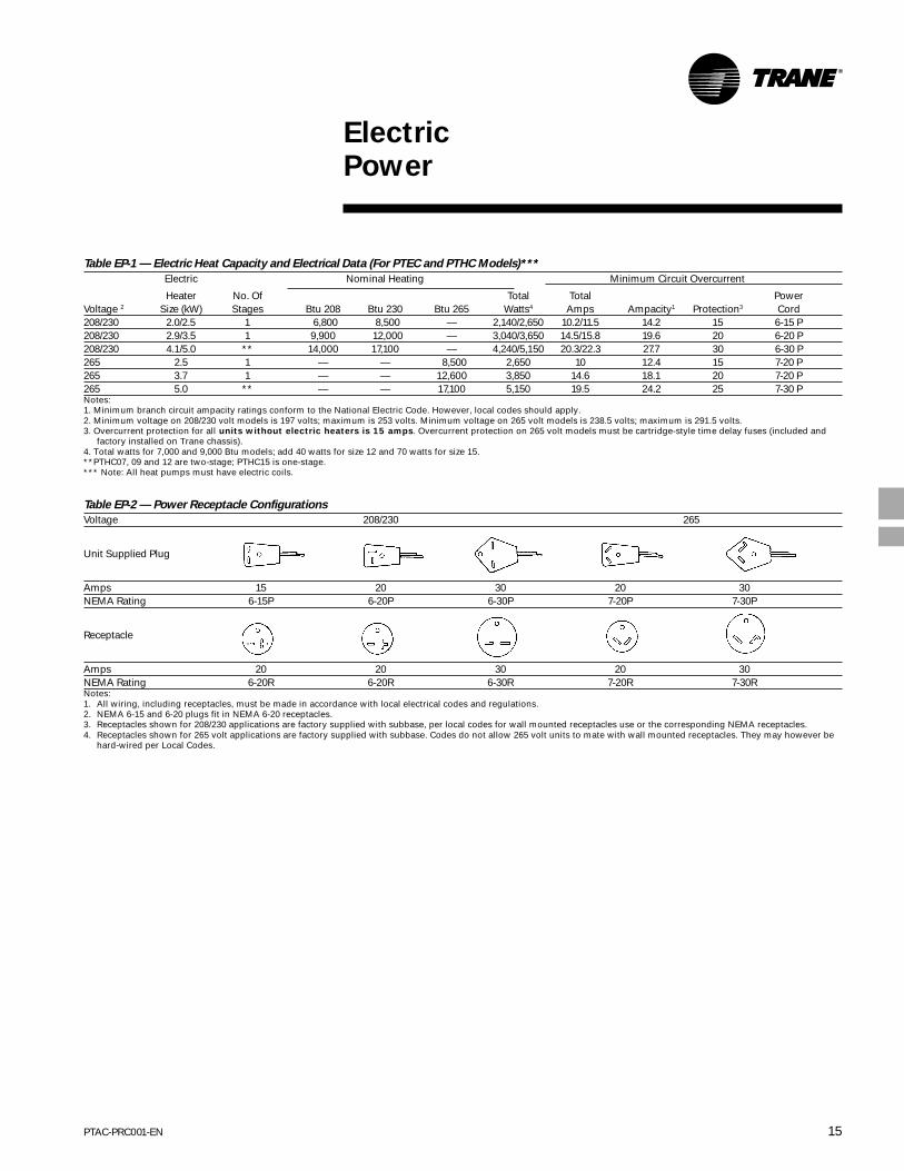
ElectricPower
Table EP-1 — Electric Heat Capacity and Electrical Data (For PTEC and PTHC Models)***
Electric Nominal Heating Minimum Circuit Overcurrent
Heater No. Of Total Total PowerVoltage 2 Size (kW) Stages Btu 208 Btu 230 Btu 265 Watts4 Amps Ampacity1 Protection3 Cord208/230 2.0/2.5 1 6,800 8,500 — 2,140/2,650 10.2/11.5 14.2 15 6-15 P208/230 2.9/3.5 1 9,900 12,000 — 3,040/3,650 14.5/15.8 19.6 20 6-20 P208/230 4.1/5.0 ** 14,000 17,100 — 4,240/5,150 20.3/22.3 27.7 30 6-30 P265 2.5 1 — — 8,500 2,650 10 12.4 15 7-20 P265 3.7 1 — — 12,600 3,850 14.6 18.1 20 7-20 P265 5.0 ** — — 17,100 5,150 19.5 24.2 25 7-30 PNotes:1. Minimum branch circuit ampacity ratings conform to the National Electric Code. However, local codes should apply.2. Minimum voltage on 208/230 volt models is 197 volts; maximum is 253 volts. Minimum voltage on 265 volt models is 238.5 volts; maximum is 291.5 volts.3. Overcurrent protection for all units without electric heaters is 15 amps. Overcurrent protection on 265 volt models must be cartridge-style time delay fuses (included and
factory installed on Trane chassis).4. Total watts for 7,000 and 9,000 Btu models; add 40 watts for size 12 and 70 watts for size 15.**PTHC07, 09 and 12 are two-stage; PTHC15 is one-stage.*** Note: All heat pumps must have electric coils.
Table EP-2 — Power Receptacle Configurations
Voltage 208/230 265
Unit Supplied Plug
Amps 15 20 30 20 30NEMA Rating 6-15P 6-20P 6-30P 7-20P 7-30P
Receptacle
Amps 20 20 30 20 30NEMA Rating 6-20R 6-20R 6-30R 7-20R 7-30RNotes:1. All wiring, including receptacles, must be made in accordance with local electrical codes and regulations.2. NEMA 6-15 and 6-20 plugs fit in NEMA 6-20 receptacles.3. Receptacles shown for 208/230 applications are factory supplied with subbase, per local codes for wall mounted receptacles use or the corresponding NEMA receptacles.4. Receptacles shown for 265 volt applications are factory supplied with subbase. Codes do not allow 265 volt units to mate with wall mounted receptacles. They may however be
hard-wired per Local Codes.

PTAC-PRC001-EN16
Dimension andWeights
Unit with Wall Sleeve and Subbase Accessory
Top View
Front View Right Side View
Notes:1. Allow a minimum of 31/4” clearance between cabinet and floor to permit installation of options subbase.2. Allow minimum of 3” clearance between cabinet and side walls to permit front panel removal.3. Drain tube can be mounted either right side, left side or bottom of sleeve. Bottom drain to be located by customer. Drain kit shipped separate.4. Unit provides 20 percent outside air.5. Detachable cord ships attached to unit. Cord can be removed for direct attachment of building wiring or wiring from junction box kit.6. For U.S. approval — 265 volt units and units with duct packages must have permanent wiring connection. Permanent wiring requirement can be met either by supplying
afull length subbase for concealed cord connection or by direct wiring with junction box kit.7. Control door provided on standard unit for access to controls.

17PTAC-PRC001-EN
Dimension andWeights
Field Supplied Extension
PTAC-PRC001-EN18
Dimension andWeights
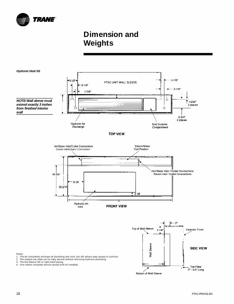
Hydronic Heat Kit
NOTE: Wall sleeve mustextend exactly 3 inchesfrom finished interiorwall
Notes:1. This kit completely encloses all plumbing and coils, but still allows easy access to controls.2. The chassis can slide out for easy service without removing hydronic plumbing.3. The kits feature left or right-hand piping.4. Unit retains complete service access with kit installed.

19PTAC-PRC001-EN
Dimension andWeights
Duct PackageWhen two adjacent rooms need to be conditioned, a main duct kit and a duct extension kit are possible options. These kits transferair from one room to another, yet allow different air flows for the rooms (airflow distribution can be adjusted from65/45 to 80/20.)
Front View
Duct Termination Kit
The Duct Termination Kitincludes a grille and asleeve for fitting duct orduct extension throughthe wall.

PTAC-PRC001-EN20
MechanicalSpecifications
Unit Chassis
Each unit will be slide-out design shippedwith room cabinet front installed. Unitchassis will have the ability to be installedwith zero reversing clearance fromfinished floor. An electrical power cordwill be included with chassis andinstalled by the manufacturer to assureproper NEMA 6 or 7 configuration andUL approved length. Unit will be testedfor conformance to ASTME waterinfiltration specification ASTME 331-86which assures no water infiltration whentested at eight inches of rain per hour at63 mph wind for 15 minutes.
Room Cabinet/Front Panel
The room cabinet/front panel will havesloped discharge so that obstructions arenot placed on unit. The dischargeconditioned air can be directed into theroom at an angle of 15 to 40 degreesfrom the vertical position. The dischargegrille will be a polycarbonate material toresist bending, cracking, rusting andcorrosion. The front panel will be able tobe field secured to chassis to inhibittampering. Cabinet depth will be seven-inch to minimize unit’s impact on roomspace.
Filter
The filter will be accessible withoutremoving room front. Filter material willbe nylon mesh, permanent cleanable.
Condenser/Evaporator Fans
One direct drive with a permanent splitcapacitor two-speed motor. Thecondenser fan will be propeller type andthe indoor evaporator fan will be acentrifugal blower type.
Cooling Condensate Removal
High humidity conditions may call forcondensate removal system. Theoutdoor fan diffuses water directly on tothe outdoor condenser coil for rapidevaporation and increased coolingefficiency.
Compressor
The compressor will be hermeticallysealed, internally isolated, rotary-typeand permanently mounted on rubberisolators. No removal or adjustment ofcompressor hold down bolts will berequired during installation.
Coils
Coils will have rifled copper tubingexpanded into rippled-edge louveredaluminum fins.
Heat Pumps
Heat pumps will include a changeoverthermostat that senses an outside coilswitch-over temperature of 25°F,lock-open refrigerant valve during heatpump operation, temperature-activateddefrost drain and automatic emergencyheat operation to override the heatpump’s changeover thermostat andbring on electric resistance heaters in theevent of a sealed system failure. Unit willnot operate compressor and electricheaters simultaneously.
Outside Air Damper/Vent Control
The vent control will allow 65 to 70 cfmof fresh air to be drawn into the room.This fresh air can provide ventilationwhen the blower is operating. To obtainaccess to the vent control, remove thecabinet front. The vent control lever is onthe left side of the chassis. The controllever must be rotated to either open orclose the damper. Actual vent cfmperformance will vary due to applicationand installation conditions.
Filtered Outdoor Air Intake
The outdoor air intake will be filteredwith a talc-filled polypropylene filter thatwill reduce dust from coming into theroom.
Paint System Corrosion Protection
All units are built with hot-dippedgalvanized steel. Metal parts are then runthrough a six-stage zinc phosphatecleaner/pretreatment, painted with acathodic electroplating of an epoxy resinpaint and baked for 20 minutes at 350°F.All exterior parts that are exposed tosunlight get an additional coating ofpolyester and are baked for 20 minutesat 350°F for additional protection fromthe fading effects of ultraviolet rays. Thispaint process makes the unit highlyresistant to normal rust, corrosion andfading. It is the best paint process in theindustry today.
Corrosion-Resistant Chassis (StandardOption)
The condenser coil is painted usingcathodic electrocoat. The bottom ¼ of thecompressor is coated with a water borneresin. The outdoor side of interior partsare top coated, in addition, the base panis cathodic electrocoated.

21PTAC-PRC001-EN
MechanicalSpecifications
Unit Controls
The unit controls will be full solid-stateand accessible from the top. Thestandard unit mounted controls willinclude two rotary (switch) knobscontrolling unit operational andtemperature mode. The unit operationalswitch includes:• Off position.• Fan only — unit operates on low fan
speed.• Low cool — unit operates on low fan
speed to circulate air for cooling.• High cool — unit operates on high fan
speed to circulate air for cooling.• Low heat — unit operates on low fan
speed to circulate air for heating.• High heat — unit operates on high fan
speed to circulate air for heating.
Temperature Switch
The temperature switch is controlled byturning the knob clockwise for a coolerroom temperature; turning itcounterclockwise will provide a warmerroom temperature. Adjusting thethermostat to the mid setting (vertical)will set the room temperature atapproximately 75°F.
Remote Control Operation
To operate units with remotethermostats, the Standard/Remote unitmounted switch must be set to theremote position. When in the remoteposition, the unit will only respond to thewall-mounted thermostat inputs. Unitwill operate on low or high fan.
Remote Thermostat/Sensor Terminals
These terminals provide control inputsfor a remote thermostat or sensor.
Front Desk Control Terminals
These terminals provide control inputsfor a front desk switch.
Load Shedding Terminals
The LS/IN terminals will provide aconnection for a switch that can beadded to close the circuit and lockout thecompressor and electric heat when thepower company or energy managementsystem is trying to reduce its load for aspecific time.
On Board Diagnostics
An LED light will flash a code displaying8 conditions: Control OK, 24 Vac FuseBlown, ICT (Indoor Coil Temperature)Probe Failure, Mode Switch Failure,Potentiometer Failure, Bad ThermostatInput Failure, Bad Communications inSlave Mode, and IAT (Indoor AirTemperature) Failure. A spare 500 MAfuse has been provided on the board.
Temperature Limiter
The temperature limiting feature canreduce energy costs by controlling themaximum temperature in heating andthe minimum temperature in cooling.
Room Freeze Protection
Freeze protection is built into all unitsand will activate the electric resistanceheater (when it senses a temperature of40°F room temperature) to maintain anabove freezing temperature at thesensor.
Fan Cycle Switch
The fan cycle switch sets the operationalmode of the fan. In the ON position, thefan will run continuously whenever theunit is in the heat or cool position. In theAUTO position, the fan will cycle on andoff with the compressor or electric heaterwhen the unit is in the cool or heatmode.
Automatic Emergency Heat StagedThermostat
On every unit mounted control heatpump, electric heat engagesautomatically if the sealed system orcompressor fails.
Compressor Time Delay
The compressor will not try to restartonce running or until approximatelythree minutes have elapsed aftershutdown.

PTAC-PRC001-EN22
Options
Wall Sleeves
Wall sleeves shall be industry standardsize of 13¾”D x 42”W x 161/16”H.
Extended Wall Sleeves
Extended wall sleeves shall be industrystandard size of 18”D x 42”W x 161/16”Hor 24” D x 42”W x 161/16”H.
Drain Kit
Drain kit attaches to the bottom of thewall sleeve for directional controlledinternal or external disposal ofcondensate and defrost water.
Outdoor Grilles
Outdoor grilles are available asarchitectural extruded, anodizedaluminum and four standard colors.Special colors are also available orstandard stamped aluminum.
Condenser Baffle Kit
The condenser baffle kit is requiredwhen replacing an existing packagedterminal unit and/or the original outdoorgrille is not made by Trane. These bafflesare required to deflect discharge airaway from the inlet, preventingrecirculation of hot condenser air.
Leveling Legs Kit
Attaches easily to the wall sleeve forsupport and accurate unit leveling onunits without subbases. Adjustable from25/8” to 5 ¼”.
Subbases
Subbases are prewired to facilitate fieldelectrical connections and include aNEMA 6 or 7 configuration electricalreceptacle. The subbases include twoleveling screws for sleeve support andaccurate unit leveling during installation.Subbases include locations for fieldinstallation of physical disconnectswitches, cartridge-style fuse holdersand circuit breakers. Side skirts will beincluded with subbases.
Power Disconnect Switch Kit
A power disconnect switch must beinstalled in hard-wire junction orsubbase for use as a physical disconnectwhere required by local codes.
Circuit Breaker Kit
A circuit breaker kit is installed in thesubbase to provide overcurrentprotection for proper 208/230 voltamperage. Can also be used as aphysical disconnect where local codespermit 208/230 volts.
Fuse Holder Kit
Fuses are included in 265 volt units. For208/230 volts, these kits allow fusing in15, 20 and 30 amps. Fuses are notincluded. Fuse holders must be installedin the unit or subbase.
Hard-Wire Junction Box Kit
Provides for easy electrical connectionwhen permanent wiring is required.Hard-wire kit must be used on 265 voltunits if subbases are not used.
Duct Transition and Extended Kit
A main duct transition piece will attach tothe discharge of the unit and a ductextension will be attached to thetransition piece to carry up to 40 percentof the conditioned air to the adjoiningroom.
Powered Outside Ventand Damper Kit
An optional power vent kit can beinstalled to increase cfm to 95. Thepower damper will automatically openwhen the unit is operating and closewhen not powered. Actual vent cfmperformance will vary due to applicationand installation conditions.
Hydronic Heat Kit
The hydronic heat kit is a field-installedpackage that can attach to airconditioners to provide central systemhot water or steam heat capability on topof units. The kit includes left or right-handpiping. The units retain complete serviceaccess with kit installed.
Control Valves
24 volt water valves are available ineither two-way or three-way for 208/230volt units and 265 volt units. 24 voltsteam valves are also available for208/230 and 265 volt units.
Remote/Wall Thermostats
Manual changeover thermostat
One-stage heat, One-stage cool and OffSwitch.
Automatic changeover thermostat withTwo-stage Heat and One-stage Cool andOff Switch.
Two-stage Heat (heat pump only) Firststage brings on electric coil when roomtemperature is more than 3.8°F coolerthan thermostat setting; then electricheat will turn off and heat pump cycleson. Also one-stage Cool with ManualChangeover.
Two-stage Heat and One-stage Cool withManual Changeover and Programmable.
Remote Temperature Sensor
This temperature sensor overridesstandard unit mounted sensor to allowtemperature sensing on internal wall formore accurate temperature control.
Condensate Removal Pump —HeatPump Only
The internal condensate pump serves asan effective means for disposing ofcondensate generated during heat pumpoperation by transferring it to the indoorcoil. The warm coil surface and the warmroom air help in evaporation of thecondensate while adding humidity to theroom. As with any equipment of thistype, the addition of this kit will decreasethe sensible heating capacity of the unit.This kit is not intended for use inseacoast or corrosive environments.
Note: Under extreme high humidity conditions, theinternal condensate pump may not be able to dispose ofall the condensate produced, and condensate wouldthen drip from the outside of the wall sleeve. If thiscondensation is unacceptable, then a drain system(including factory approved drain kit for the wall sleeve)should be installed.
Control Cover Key Lock Kit
Allows the owner to lock the controlpanel access to prevent unauthorizedoperation.
Options

23PTAC-PRC001-EN
Options
Subbase Kit
The fully skirted subbase conceals wiringwhile providing strong support. A plug-inreceptacle and field wiring accessexpedites installation. Electricalaccessories such as fuse holders, circuitbreakers and disconnect switches meetN.E.C. requirements.
Fuse Holder Kit
Cartridge-style fuses can be installed inthe fuse holder for use in the subbase orchassis. It is available in 15, 20 and 30amp and included on the 265 volt unit.
Power Disconnect Switch
The power disconnect switch can beused for 265 or 208/230 volt physicaldisconnect where required by localcodes. The switch is rated at 30 ampcapacity. The switch is for use withTrane’s standard subbases or hardwire kit.
Condensate Drain Kit
This kit attaches to the wall sleeve basepan for controlled internal or externaldisposal of condensate and defrostwater.
Outdoor Grilles
Outdoor grilles are available in stampedaluminum and an attractive extrudedaluminum architectural grille.
Security Key Locks
The installation of Trane’s security keylocks helps prevent tampering of thecontrols used to set temperature,heating and cooling functions. Locks areavailable for all PTAC models.
Remote Temperature Sensor
This sensor allows for inexpensivetemperature sensing on an internal wallfor more accurate temperature control.
Deflector Baffle Kit
The kit includes two air deflection baffles.These deflectors direct the air in towardthe center and away from the inlet toprevent recirculation of the hotcondenser air. This kit is not to be usedwhen the outdoor grille is provided byTrane.
Hard-Wire Kit
This kit is used to permanently wire tochassis when standard subbase andpower cord are not utilized.
Circuit Breaker Kit
The circuit breaker kit, available in 15, 20,25 or 30 amp, can be used with Trane’ssubbases. It gives overcurrent protectionand its location allows turning unit on oroff without tools.
Power Vent and Damper Kit
Installation of the power vent canincrease the cfm to 70. The damper willautomatically close when unit is notpowered.
Power Door Kit
Door will power open to allow fresh airwhen the unit fan is on and springclosed when the unit fan is off.

PTAC-PRC001-EN24
Warranty
Warranty Information
Standard Warranty
•Full First-Year WarrantyTrane will repair or replace, free ofcharge including labor, any part whichproves to be defective due toworkmanship or materials.
•Full Five-Year Sealed SystemWarrantyTrane will repair or replace, free ofcharge including labor, the evaporator,condenser, compressor or connectingtubing which proves to be defective dueto workmanship or materials.
•Limited Second through Fifth YearWarrantyDuring the 2nd through 5th year, Tranewill provide, free of charge, functionalparts which prove to be defective due toworkmanship or materials. Componentscovered are switches, solenoids, fanmotors, thermostats, circuit boards,factory installed heaters, blower wheel,fan propeller and capacitor.
This limited warranty does not includediagnostic time, labor or anytransportation and reinstallation chargesthat may be required.

Literature Order Number
File Number
Supersedes
Stocking LocationThe Trane CompanyAn American Standard Companywww.trane.com
For more information contact your localdistributor (dealer), local district office, ore-mail us at [email protected]
Since The Trane Company has a policy of continuous product and product data improvement, it reserves theright to change design and specifications without notice.
PTAC-PRC001-EN
PL-UN-PTAC-PRC001-EN-10-00
PTAC-DS-1 6/98
Inland - La Crosse