pacing and icds 4th e… · © kenneth a. ellenbogen, md, 2005 blackwell publishing, inc., 350 main...
TRANSCRIPT


Cardiac Pacing and ICDsFourth Edition


Cardiac Pacing and ICDsFourth Edition
Kenneth A. Ellenbogen, MDKontos Professor of Medicine
Director, Electrophysiology and Pacing LaboratoryVirginia Commonwealth University Medical Center
Richmond,Virginia
Mark A. Wood, MDProfessor of Medicine
Assistant Director, Electrophysiology and Pacing LaboratoryVirginia Commonwealth University Medical Center
Richmond,Virginia
© Kenneth A. Ellenbogen, MD, 2005
Blackwell Publishing, Inc., 350 Main Street, Malden, Massachusetts 02148-5018, USABlackwell Publishing Ltd, 9600 Garsington Road, Oxford OX4 2DQ, UKBlackwell Publishing Asia Pty Ltd, 550 Swanston Street, Carlton,Victoria 3053, Australia
All rights reserved. No part of this publication may be reproduced in any form or by any electronic or mechanical means,including information storage and retrieval systems, without permission in writing from the publisher, except by a reviewerwho may quote brief passages in a review.
05 06 07 08 5 4 3 2 1
ISBN-13: 978-1-4051-0447-0ISBN-10: 1-4051-0447-3
Library of Congress Cataloging-in-Publication Data
Cardiac pacing and ICDs / [edited by] Kenneth A. Ellenbogen, Mark A. Wood.—4th ed.p. ; cm.
Includes bibliographical references and index.ISBN-13: 978-1-4051-0447-0 (pbk.)ISBN-10: 1-4051-0447-3 (pbk.)1. Cardiac pacing. 2. Implantable cardioverter-defibrillators. [DNLM: 1. Cardiac Pacing, Artificial. 2. Defibrillators,
Implantable. 3. Pacemaker, Artificial. WG 168 C26333 2005] I. Ellenbogen, Kenneth A. II. Wood, Mark A.RC684.P3C29 2005617.4¢120645—dc22
2004026975
A catalogue record for this title is available from the British Library
Acquisitions: Nancy DuffyDevelopment: Selene SteneckProduction: Debra MurphyCover design: Electronic Illustrators GroupTypesetter: SNP Best-set Typesetter Ltd., Hong KongPrinted and bound by Edwards Brothers in Ann Arbor, MI
For further information on Blackwell Publishing, visit our website: www.blackwellmedicine.com
Notice: The indications and dosages of all drugs in this book have been recommended in the medical literature andconform to the practices of the general community. The medications described do not necessarily have specific approval bythe Food and Drug Administration for use in the diseases and dosages for which they are recommended. The packageinsert for each drug should be consulted for use and dosage as approved by the FDA. Because standards for usage change,it is advisable to keep abreast of revised recommendations, particularly those concerning new drugs.
The publisher’s policy is to use permanent paper from mills that operate a sustainable forestry policy, and which has beenmanufactured from pulp processed using acid-free and elementary chlorine-free practices. Furthermore, the publisherensures that the text paper and cover board used have met acceptable environmental accreditation standards.

To my wife, Phyllis, whose support and encouragement helped make this projectsuccessful, and to my children, Michael, Amy, and Bethany for their patience andlove.
—Kenneth A. Ellenbogen, MD
To my wife, Helen E. Wood, PhD, for her unquestioning love and support, and tomy parents, William B. Wood, PhD, and Donna S. Wood, EdD, for their enduringexamples of scholarship.
—Mark A. Wood, MD


Contents
vii
Contributors viiiPreface x
1. Indications for Permanent and Temporary Cardiac Pacing 1Pugazhendhi Vijayaraman, Robert W. Peters, and Kenneth A. Ellenbogen
2. Basic Concepts of Pacing 47G. Neal Kay
3. Hemodynamics of Cardiac Pacing 122Richard C.Wu and Dwight W. Reynolds
4. Temporary Cardiac Pacing 163Mark A.Wood and Kenneth A. Ellenbogen
5. Techniques of Pacemaker Implantation and Removal 196Jeffrey Brinker and Mark G. Midei
6. Pacemaker Timing Cycles 265David L. Hayes and Paul A. Levine
7. Evaluation and Management of Pacing System Malfunctions 322Paul A. Levine
8. The Implantable Cardioverter Defibrillator 380Michael R. Gold
9. Cardiac Resynchronization Therapy 415Michael O. Sweeney
10. ICD Follow-up and Troubleshooting 467Henry F. Clemo and Mark A.Wood
11. Follow-up Assessments of the Pacemaker Patient 500Mark H. Schoenfeld and Mark L. Blitzer
Index 545

Contributors
viii
Mark L. Blitzer, MDInstructor in MedicineYale University School of MedicineHospital of Saint RaphaelNew Haven, Connecticut
Jeffrey Brinker, MDProfessor of MedicineJohns Hopkins University School of
MedicineJohns Hopkins HospitalBaltimore, Maryland
Henry F. Clemo, MD, PhDAssociate Professor of MedicineVirginia CommonwealthUniversity School of MedicineRichmond,Virginia
Michael R. Gold, MD, PhDMichael E. Assey Professor of
MedicineChief, Division of CardiologyMedical Director, Heart and Vascular
CenterMedical University of South CarolinaCharleston, South Carolina
David L. Hayes, MDChair, Cardiovascular DiseasesMayo ClinicProfessor of MedicineMayo Clinic College of MedicineRochester, Minnesota
G. Neal Kay, MDProfessor of MedicineUniversity of Alabama at BirminghamUniversity of Alabama HospitalBirmingham, Alabama
Paul A. Levine, MDClinical Professor of MedicineLoma Linda University School of
MedicineLoma Linda University Medical
CenterLoma Linda, CaliforniaVice President and Medical DirectorSt. Jude Medical CRMDSylmar, California
Mark G. Midei, MDAssistant Professor of MedicineJohns Hopkins University School of
MedicineMidatlantic Cardiovascular AssociatesBaltimore, Maryland

Robert W. Peters, MDProfessor of MedicineUniversity of Maryland School of
MedicineChief of CardiologyVeterans Administration Medical CenterBaltimore, Maryland
Dwight W. Reynolds, MDProfessor of Medicine andChief, Cardiovascular SectionThe University of Oklahoma Health
Sciences CenterChief of StaffOU Medical CenterOklahoma City, Oklahoma
Mark H. Schoenfeld, MDClinical Professor of MedicineYale University School of MedicineDirector, Cardiac Electrophysiology and
Pacer LaboratoryHospital of Saint RaphaelNew Haven, Connecticut
Michael O. Sweeney, MDAssistant ProfessorHarvard Medical SchoolCardiac Arrhythmia ServiceBrigham and Women’s HospitalBoston, Massachusetts
Pugazhendhi Vijayaraman, MDAssistant Professor of MedicineVirginia CommonwealthUniversity School of MedicineCo-Director, Cardiac Electrophysiology
LabMcGuire VA Medical CenterRichmond,Virginia
Richard C. Wu, MDAttending Physician, Clinical
Electrophysiology LaboratoryAssistant Professor of MedicineCardiac Arrhythmia Research InstituteThe University of Oklahoma Health
Sciences CenterOklahoma City, Oklahoma
CONTRIBUTORS
ix

Preface
x
It has been almost five years since our last edition was published. Much has happened in the world of cardiology and especially device therapy since then.A major advance has been the development of cardiac resynchronization therapyas heralded by the development of biventricular pacemakers and implantablecardioverter defibrillators (ICDs). Cardiac resynchronization therapy representsan important new device therapy for patients with congestive heart failure. Itsimpact on the care of large numbers of patients requires that cardiologistsbecome familiar with the physiology, and implantation and follow-up of thesenew devices.Additionally, several recent clinical trials of ICDs has led to a markedincrease in defibrillator implantation. It is important that cardiologists and otherhealthcare providers become familiar with the results of these clinical trials.
These exciting new developments have been the stimulus for Dr. Mark A.Wood and I to prepare the fourth edition. Like our previous editions, we havefocused on providing a “clinician” friendly book. We have strived to continueour tradition of providing numerous tables, examples and figures that illustrateimportant teaching points.We have gone through the entire book and replaced“old” figures, or “poorly reproduced figures” with newer more relevant figures.We have added numerous tables and updated each chapter thoroughly to keepthe healthcare provider, at whatever level, current with the latest developmentsin clinical device therapy. There is a new comprehensive chapter on cardiacresynchronization therapy, and the information on ICDs has been increasedgreatly throughout the text to emphasize their increasing importance. The bib-liographies have been shortened and we have made every attempt to includerecent references through 2004. This edition promises to provide a thoroughlyreadable textbook for individuals at all levels caring for device patients.
Finally, this revision was once again made possible because of the hard workof many people. I want to thank the new authors and co-authors who helpedwith this edition. It is really the contributors who have made this book so suc-cessful. We are indebted to them for taking time from their busy clinical com-mitments to continue their contributions to this edition. My co-editor, Dr. MarkA. Wood, toiled over each chapter making sure the tables and figures wereupdated and did not rest until each figure was as close to perfect as possible.His commitment to scholarship is a constant reminder to me about the impor-tance of academic medicine. We are also indebted to Dr. George W. Vetrovec,Chairman of Cardiology who has provided unquestioning support and encour-agement for all our academic and scholarly activities.
Kenneth A. Ellenbogen, M.D.

1
ANATOMYTo understand the principles and concepts involved in cardiac pacing more com-pletely, a brief review of the anatomy and physiology of the specialized con-duction system is warranted (Table 1.1).1
Sinoatrial NodeThe sinoatrial (SA) node is a subepicardial structure located at the junction ofthe right atrium and superior vena cava. It has abundant autonomic innerva-tion and a copious blood supply; it is often located within the adventitia of thelarge SA nodal artery, a proximal branch of the right coronary artery (55%), orthe left circumflex coronary artery. Histologically, the SA node consists of adense framework of collagen that contains a variety of cells, among them thelarge, centrally located P cells, which are thought to initiate impulses; transi-tional cells, intermediate in structure between P cells and regular atrial myocar-dial cells; and Purkinje-like fiber tracts, extending through the perinodal areaand into the atrium.
Atrioventricular NodeThe atrioventricular (AV) node is a small subendocardial structure within theinteratrial septum located at the convergence of the specialized conduction tractsthat course through the atria. Like the SA node, the AV node has extensiveautonomic innervation and an abundant blood supply from the large AV nodalartery, a branch of the right coronary artery in 90% of cases, and also from septalbranches of the left anterior descending coronary artery. Histologic examinationof the AV node reveals a variety of cells embedded in a loose collagenousnetwork including P cells (although not nearly as many as in the SA node),atrial transitional cells, ordinary myocardial cells, and Purkinje cells.
His BundlePurkinje fibers emerging from the area of the distal AV node converge gradu-ally to form the His bundle, a narrow tubular structure that runs through the
1Indications for Permanent and
Temporary Cardiac PacingPugazhendhi Vijayaraman, Robert W. Peters, and Kenneth A. Ellenbogen
CA
RD
IAC
PAC
ING
AN
D IC
DS
2
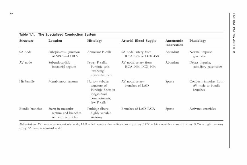
Table 1.1. The Specialized Conduction System
Structure Location Histology Arterial Blood Supply Autonomic PhysiologyInnervation
SA node Subepicardial; junction Abundant P cells SA nodal artery from Abundant Normal impulse of SVC and HRA RCA 55% or LCX 45% generator
AV node Subendocardial; Fewer P cells, AV nodal artery from Abundant Delays impulse,interatrial septum Purkinje cells, RCA 90%, LCX 10% subsidiary pacemaker
“working”myocardial cells
His bundle Membranous septum Narrow tubular AV nodal artery, Sparse Conducts impulses fromstructure of branches of LAD AV node to bundlePurkinje fibers in brancheslongitudinalcompartments;few P cells
Bundle branches Starts in muscular Purkinje fibers; Branches of LAD, RCA Sparse Activates ventriclesseptum and branches highly variableout into ventricles anatomy
Abbreviations: AV node = atrioventricular node; LAD = left anterior descending coronary artery; LCX = left circumflex coronary artery; RCA = right coronaryartery; SA node = sinoatrial node.
membranous septum to the crest of the muscular septum, where it divides intothe bundle branches. The His bundle has relatively sparse autonomic innerva-tion, although its blood supply is quite ample, emanating from both the AVnodal artery and septal branches of the left anterior descending artery. Longi-tudinal strands of Purkinje fibers, divided into separate parallel compartmentsby a collagenous skeleton, can be discerned by histologic examination of theHis bundle. Relatively sparse P cells can also be identified, embedded withinthe collagen.
Bundle BranchesThe bundle branch system is an enormously complex network of interlacingPurkinje fibers that varies greatly among individuals. It generally starts as oneor more large fiber bands that split and fan out across the ventricles until theyfinally terminate in a Purkinje network that interfaces with the myocardium. Insome cases, the bundle branches clearly conform to a trifascicular or quadrifas-cicular system. In other cases, however, detailed dissection of the conductionsystem has failed to delineate separate fascicles. The right bundle is usually asingle, discrete structure that extends down the right side of the interventricu-lar septum to the base of the anterior papillary muscle, where it divides intothree or more branches. The left bundle more commonly originates as a verybroad band of interlacing fibers that spread out over the left ventricle,sometimes in two or three distinct fiber tracts. There is relatively little autonomic innervation of the bundle branch system, but the blood supply isextensive, with most areas receiving branches from both the right and left coronary systems.
PHYSIOLOGYThe SA node has the highest rate of spontaneous depolarization (automaticity)in the specialized conduction system, and under ordinary circumstances, it is themajor generator of impulses. Its unique location astride the large SA nodal artery provides an ideal milieu for continuous monitoring and instantaneousadjustment of heart rate to meet the body’s changing metabolic needs. The SA node is connected to the AV node by several specialized fiber tracts, thefunction of which has not been fully elucidated. The AV node appears to havethree major functions: It delays the passing impulse for approximately 0.04seconds under normal circumstances, permitting complete atrial emptying with appropriate loading of the ventricle; it serves as a subsidiary impulse generator, as its concentration of P cells is second only to that of the SA node;and it acts as a type of filter, limiting ventricular rates in the event of an atrialtachyarrhythmia.
The His bundle arises from the convergence of Purkinje fibers from theAV node, although the exact point at which the AV node ends and the Hisbundle begins has not been delineated either anatomically or electrically. Theseparation of the His bundle into longitudinally distinct compartments by the
INDICATIONS FOR PERMANENT AND TEMPORARY CARDIAC PACING
3

collagenous framework allows for longitudinal dissociation of electrical impulses.Thus a localized lesion below the bifurcation of the His bundle (into the bundlebranches) may cause a specific conduction defect (e.g., left anterior fascicularblock). The bundle branches arise as a direct continuation of the His bundlefibers. Disease within any aspect of the His bundle branch system may causeconduction defects that can affect AV synchrony or prevent synchronous rightand left ventricular activation. The accompanying hemodynamic consequenceshave considerable clinical relevance. These consequences have provided theimpetus for some of the advances in pacemaker technology, which will beaddressed in later chapters of this book.
Although a detailed discussion of the histopathology of the conductionsystem is beyond the scope of the present chapter, it is worth noting that con-duction system disease is often diffuse. For example, normal AV conductioncannot necessarily be assumed when a pacemaker is implanted for a disorderseemingly localized to the sinus node. Similarly, normal sinus node functioncannot be assumed when a pacemaker is implanted in a patient with AV block.
Indications for Permanent PacemakersThe decision to implant a permanent pacemaker is an important one and shouldbe based on solid clinical evidence. A joint committee of the American Collegeof Cardiology and the American Heart Association was formed in the 1980s toprovide uniform criteria for pacemaker implantation.These guidelines were firstpublished in 1984 and most recently revised in 2002.2,3 It must be realized,however, that medicine is a constantly changing science, and absolute and relative indications for permanent pacing may change as a result of advances inthe diagnosis and treatment of arrhythmias. It is useful to keep the ACC/AHAguidelines in mind when evaluating a patient for pacemaker implantation.Whenapproaching a patient with a documented or suspected bradyarrhythmia, it isimportant to take the clinical setting into account. Thus, the patient’s overallgeneral medical condition must be considered as well as his or her occupationor desire to operate a motor vehicle or equipment where the safety of otherindividuals may be at risk.
In the ACC/AHA classification, there are three classes of indications forpermanent pacemaker implantation, defined as follows:
Class IConditions for which there is evidence and/or general agreement that a pace-
maker implantation is beneficial, useful, and effective.
Class IIConditions for which there is conflicting evidence and/or a divergence of
opinion about the usefulness/efficacy of pacemaker implantation.Class IIa: Weight of evidence/opinion in favor of efficacyClass IIb: Usefulness/efficacy less well established by evidence/opinion
CARDIAC PACING AND ICDS
4

Class IIIConditions for which there is evidence and/or general agreement that a pace-
maker is not useful/effective and in some cases may be harmful.
Level of EvidenceAdditionally, the ACC/AHA Committee ranked evidence supporting their rec-ommendations by the following criteria.
Level A: Data derived from multiple randomized trials involving a large numberof patients.
Level B: Data derived from a limited number of trials involving a relatively smallnumber of patients or from well-designed analyses of nonrandomized studiesor data registries.
Level C: Recommendations derived from the consensus of experts.
ACQUIRED ATRIOVENTRICULAR BLOCKAcquired atrioventricular block with syncope (e.g., Stokes-Adams attacks) washistorically the first indication for cardiac pacing.The site of AV block (e.g., AVnode, His bundle, or distal conduction system) will to a great extent determinethe adequacy and reliability of the underlying escape rhythm (Figs. 1.1–1.3). Itis worth noting that, in the presence of symptoms documented to be due toAV block, permanent pacing is indicated, regardless of the site of the block (e.g.,above the His bundle as well as below the His bundle). Because of differentindications for permanent pacing heart block due to acute myocardial infarc-tion, congenital AV block and increased vagal tone are discussed in other sections.
INDICATIONS FOR PERMANENT AND TEMPORARY CARDIAC PACING
5
Figure 1.1. An elderly man with underlying left bundle branch block was prescribedpropafenone for prevention of atrial fibrillation. He was admitted to the hospital becauseof syncopal episode and the following rhythm strip was obtained, demonstrating devel-opment of complete heart block. Propafenone is a class IC antiarrhythmic drug that hasthe potential to cause AV block in patients who have a conduction system disease.
CARDIAC PACING AND ICDS
6
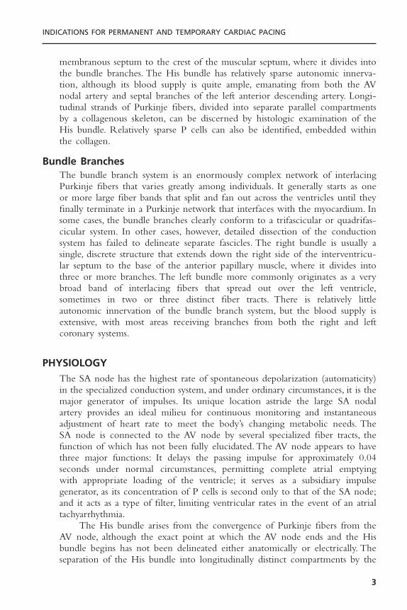
Rate of Escape Rhythm vs. Site of Block
INFRA — HIS
INTRA — HIS
AVN
Figure 1.2. A diagram outlining the rate of the escape rhythm in patients with high-grade AV block. As can be seen, the escape rate in a patient with block at the AV nodeis usually considerably faster than in individuals with intra-Hisian or infra-Hisian block,although there is considerable overlap between groups.
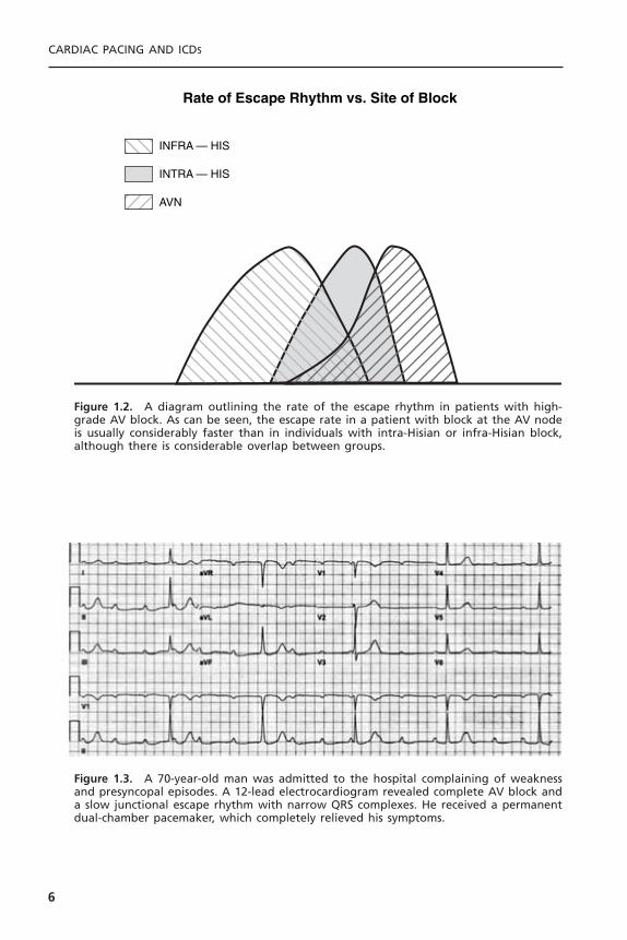
Figure 1.3. A 70-year-old man was admitted to the hospital complaining of weaknessand presyncopal episodes. A 12-lead electrocardiogram revealed complete AV block anda slow junctional escape rhythm with narrow QRS complexes. He received a permanentdual-chamber pacemaker, which completely relieved his symptoms.
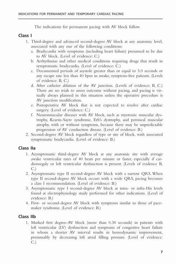
The indications for permanent pacing with AV block follow.
Class I1. Third-degree and advanced second-degree AV block at any anatomic level,
associated with any one of the following conditions:a. Bradycardia with symptoms (including heart failure) presumed to be due
to AV block. (Level of evidence: C.)b. Arrhythmias and other medical conditions requiring drugs that result in
symptomatic bradycardia. (Level of evidence: C.)c. Documented periods of asystole greater than or equal to 3.0 seconds or
any escape rate less than 40 bpm in awake, symptom-free patients. (Levelsof evidence: B, C.)
d. After catheter ablation of the AV junction. (Levels of evidence: B, C.)There are no trials to assess outcome without pacing, and pacing is vir-tually always planned in this situation unless the operative procedure isAV junction modification.
e. Postoperative AV block that is not expected to resolve after cardiacsurgery. (Level of evidence: C.)
f. Neuromuscular diseases with AV block, such as myotonic muscular dys-trophy, Kearns-Sayre syndrome, Erb’s dystrophy, and peroneal muscularatrophy, with or without symptoms, because there may be unpredictableprogression of AV conduction disease. (Level of evidence: B.)
2. Second-degree AV block regardless of type or site of block, with associatedsymptomatic bradycardia. (Level of evidence: B.)
Class IIa1. Asymptomatic third-degree AV block at any anatomic site with average
awake ventricular rates of 40 beats per minute or faster, especially if car-diomegaly or left ventricular dysfunction is present. (Levels of evidence B,C.)
2. Asymptomatic type II second-degree AV block with a narrow QRS. Whentype II second-degree AV block occurs with a wide QRS, pacing becomesa class I recommendation. (Level of evidence: B.)
3. Asymptomatic type I second-degree AV block at intra- or infra-His levelsfound at electrophysiology study performed for other indications. (Level ofevidence: B.)
4. First- or second-degree AV block with symptoms similar to those of pace-maker syndrome. (Level of evidence: B.)
Class IIb1. Marked first degree-AV block (more than 0.30 seconds) in patients with
left ventricular (LV) dysfunction and symptoms of congestive heart failure in whom a shorter AV interval results in hemodynamic improvement,presumably by decreasing left atrial filling pressure. (Level of evidence:C.)
INDICATIONS FOR PERMANENT AND TEMPORARY CARDIAC PACING
7

2. Neuromuscular diseases such as myotonic muscular dystrophy, Kearns-Sayresyndrome, Erb’s dystrophy, and peroneal muscular atrophy with any degreeof AV block (including first-degree AV block) with or without symptoms,because there may be unpredictable progression of AV conduction disease.(Level of evidence: B.)
Class III1. Asymptomatic first-degree AV block. (Level of evidence: B.)2. Asymptomatic type I second-degree AV block at the AV nodal level or not
known to be intra- or infra-Hisian. (Levels of evidence B, C.)3. AV block expected to resolve and/or unlikely to recur (e.g., drug toxicity,
Lyme disease, or during hypoxia in sleep apnea syndrome in absence of symp-toms). (Level of evidence: B.)
The majority of these diagnoses can be made from the surface electrocar-diogram. Invasive electrophysiology studies are only rarely necessary but may behelpful or of interest in elucidating the site of AV block (Figs. 1.4–1.6). Regard-ing the first two items in class II, it is likely that permanent pacemakers aremore frequently implanted in patients with wide QRS complexes and/or doc-umented infranodal block than in patients with narrow QRS complex escaperhythms.
CARDIAC PACING AND ICDS
8
Figure 1.4. This 12-lead electrocardiogram showing 2 :1 AV block was obtained as partof a routine preoperative evaluation from an asymptomatic 75-year-old woman who wasscheduled to undergo surgery for severe peripheral vascular disease. The site of block isuncertain but the presence of alternating left bundle branch block and right bundlebranch block suggests that the block is infranodal. The electrophysiologic study confirmedan infranodal block and this patient underwent permanent pacemaker implantation.Although this is a class IIa indication for pacing, it was decided that the patient couldnot truly be considered asymptomatic because her activity was limited by severe inter-mittent claudication.
INDICATIONS FOR PERMANENT AND TEMPORARY CARDIAC PACING
9
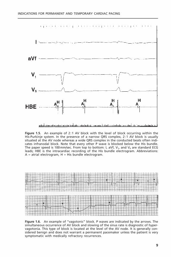
Figure 1.5. An example of 2 :1 AV block with the level of block occurring within theHis-Purkinje system. In the presence of a narrow QRS complex, 2 :1 AV block is usuallysituated at the AV node whereas a wide QRS complex in the conducted beats often indi-cates infranodal block. Note that every other P wave is blocked below the His bundle.The paper speed is 100mm/sec. From top to bottom: I, aVf, V1, and V6 are standard ECGleads; HBE is the intracardiac recording of the His bundle electrogram. Abbreviations: A = atrial electrogram, H = His bundle electrogram.
Figure 1.6. An example of “vagotonic” block. P waves are indicated by the arrows. Thesimultaneous occurrence of AV block and slowing of the sinus rate is diagnostic of hyper-vagotonia. This type of block is located at the level of the AV node. It is generally con-sidered benign and does not warrant a permanent pacemaker unless the patient is verysymptomatic with medically refractory recurrences.
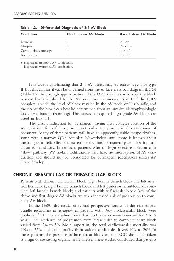
It is worth emphasizing that 2 :1 AV block may be either type I or typeII, but this cannot always be discerned from the surface electrocardiogram (ECG)(Table 1.2). As a rough approximation, if the QRS complex is narrow, the blockis most likely localized to the AV node and considered type I. If the QRScomplex is wide, the level of block may be in the AV node or His bundle, andthe site of the block can best be determined from an invasive electrophysiologicstudy (His bundle recording). The causes of acquired high-grade AV block arelisted in Box 1.1.
The class I indication for permanent pacing after catheter ablation of theAV junction for refractory supraventricular tachycardia is also deserving ofcomment. Many of these patients will have an apparently stable escape rhythm,some with a narrow QRS complex. Nevertheless, until more is known aboutthe long-term reliability of these escape rhythms, permanent pacemaker implan-tation is mandatory. In contrast, patients who undergo selective ablation of a“slow” pathway (AV nodal modification) may have no interruption of AV con-duction and should not be considered for permanent pacemakers unless AVblock develops.
CHRONIC BIFASCICULAR OR TRIFASCICULAR BLOCKPatients with chronic bifascicular block (right bundle branch block and left ante-rior hemiblock, right bundle branch block and left posterior hemiblock, or com-plete left bundle branch block) and patients with trifascicular block (any of theabove and first-degree AV block) are at an increased risk of progression to com-plete AV block.
In the 1980s, the results of several prospective studies of the role of Hisbundle recordings in asymptomatic patients with chronic bifascicular block werepublished.2–7 In these studies, more than 750 patients were observed for 3 to 5years. The incidence of progression from bifascicular to complete heart blockvaried from 2% to 5%. Most important, the total cardiovascular mortality was19% to 25%, and the mortality from sudden cardiac death was 10% to 20%. Inthese patients, the presence of bifascicular block on the ECG should be takenas a sign of coexisting organic heart disease.These studies concluded that patients
CARDIAC PACING AND ICDS
10
Table 1.2. Differential Diagnosis of 2:1 AV Block
Condition Block above AV Node Block below AV Node
Exercise + +/- or -Atropine + +/- or -Carotid sinus massage - + or +/-Isoprenaline - + or +/-
+ Represents improved AV conduction.- Represents worsened AV conduction.
with chronic asymptomatic bifascicular block and a prolonged HV interval (HV inter-val represents the shortest conduction time from the His bundle to the endo-cardium over the specialized conduction system) have more extensive organicheart disease and an increased risk of sudden cardiac death.The risk of sponta-neous progression to complete heart block is small, although it is probably
INDICATIONS FOR PERMANENT AND TEMPORARY CARDIAC PACING
11
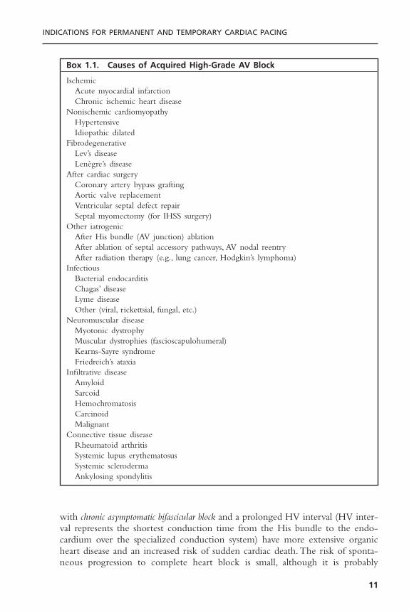
Box 1.1. Causes of Acquired High-Grade AV Block
IschemicAcute myocardial infarctionChronic ischemic heart disease
Nonischemic cardiomyopathyHypertensiveIdiopathic dilated
FibrodegenerativeLev’s diseaseLenègre’s disease
After cardiac surgeryCoronary artery bypass graftingAortic valve replacementVentricular septal defect repairSeptal myomectomy (for IHSS surgery)
Other iatrogenicAfter His bundle (AV junction) ablationAfter ablation of septal accessory pathways, AV nodal reentryAfter radiation therapy (e.g., lung cancer, Hodgkin’s lymphoma)
InfectiousBacterial endocarditisChagas’ diseaseLyme diseaseOther (viral, rickettsial, fungal, etc.)
Neuromuscular diseaseMyotonic dystrophyMuscular dystrophies (fascioscapulohumeral)Kearns-Sayre syndromeFriedreich’s ataxia
Infiltrative diseaseAmyloidSarcoidHemochromatosisCarcinoidMalignant
Connective tissue diseaseRheumatoid arthritisSystemic lupus erythematosusSystemic sclerodermaAnkylosing spondylitis
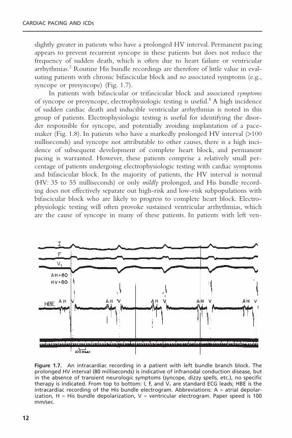
slightly greater in patients who have a prolonged HV interval. Permanent pacingappears to prevent recurrent syncope in these patients but does not reduce thefrequency of sudden death, which is often due to heart failure or ventriculararrhythmias.2 Routine His bundle recordings are therefore of little value in eval-uating patients with chronic bifascicular block and no associated symptoms (e.g.,syncope or presyncope) (Fig. 1.7).
In patients with bifascicular or trifascicular block and associated symptomsof syncope or presyncope, electrophysiologic testing is useful.8 A high incidenceof sudden cardiac death and inducible ventricular arrhythmias is noted in thisgroup of patients. Electrophysiologic testing is useful for identifying the disor-der responsible for syncope, and potentially avoiding implantation of a pace-maker (Fig. 1.8). In patients who have a markedly prolonged HV interval (>100milliseconds) and syncope not attributable to other causes, there is a high inci-dence of subsequent development of complete heart block, and permanentpacing is warranted. However, these patients comprise a relatively small per-centage of patients undergoing electrophysiologic testing with cardiac symptomsand bifascicular block. In the majority of patients, the HV interval is normal(HV: 35 to 55 milliseconds) or only mildly prolonged, and His bundle record-ing does not effectively separate out high-risk and low-risk subpopulations withbifascicular block who are likely to progress to complete heart block. Electro-physiologic testing will often provoke sustained ventricular arrhythmias, whichare the cause of syncope in many of these patients. In patients with left ven-
CARDIAC PACING AND ICDS
12
Figure 1.7. An intracardiac recording in a patient with left bundle branch block. Theprolonged HV interval (80 milliseconds) is indicative of infranodal conduction disease, butin the absence of transient neurologic symptoms (syncope, dizzy spells, etc.), no specifictherapy is indicated. From top to bottom: I, F, and V1 are standard ECG leads; HBE is theintracardiac recording of the His bundle electrogram. Abbreviations: A = atrial depolar-ization, H = His bundle depolarization, V = ventricular electrogram. Paper speed is 100mm/sec.

tricular systolic dysfunction, advanced heart failure, and bundle branch block,especially left bundle branch block and QRS interval greater than 120 milli-seconds, defibrillators with biventricular pacing have been shown to improvesymptoms from heart failure and reduce mortality.9
Barold has pointed out that the standard definition of trifascicular block isoften too loosely applied.10 Thus, in patients with right bundle branch blockand either left anterior or left posterior fascicular block or in patients with left
INDICATIONS FOR PERMANENT AND TEMPORARY CARDIAC PACING
13
Figure 1.8. A 68-year-old man was admitted complaining of recurrent dizziness andsyncope. His baseline 12-lead ECG showed a PR interval of 0.20 seconds and a rightbundle block QRS morphology. During the electrophysiologic study, the patient’s base-line HV interval was 90 milliseconds. Top: During atrial pacing at a cycle length of 600milliseconds (100 ppm), there is block in the AV node. Bottom: During pacing at 500 milli-seconds (120 ppm), there is block below the His bundle. These findings are indicative ofsevere diffuse conduction system disease. A permanent dual-chamber pacemaker wasimplanted, and the patient’s symptoms resolved. From top to bottom: I, II, III, and V1 arestandard ECG leads; intracardiac recording from the right atrial appendage (RA) and His bundle (HBE1 for the proximal His bundle and HBE2 for the distal His bundle). Abbreviations: A = atrial depolarization, H = His bundle depolarization, V = ventriculardepolarization.
bundle branch block and first-degree AV block, the site of block could be locatedeither in the His-Purkinje system or in the AV node. The term “trifascicularblock” should be reserved for alternating right and left bundle branch block orfor block of either bundle in the setting of a prolonged HV interval.
The indications for pacing in the setting of chronic bifascicular/trifascicular block are listed subsequently.
Class I1. Intermittent third-degree AV block. (Level of evidence: B.)2. Type II second-degree AV block. (Level of evidence: B.)3. Alternating bundle-branch block. (Level of evidence: C.)
Class IIa1. Syncope not demonstrated to be due to AV block when other likely causes
have been excluded, specifically ventricular tachycardia. (Level of evidence:B.)
2. Incidental finding at electrophysiology study of markedly prolonged HVinterval (greater than or equal to 100 milliseconds) in asymptomatic patients.(Level of evidence: B.)
3. Incidental finding at electrophysiology study of pacing induced infra-Hisblock that is not physiologic. (Level of evidence: B.)
Class IIb1. Neuromuscular diseases such as myotonic muscular dystrophy, Kearn-Sayre
syndrome, Erb’s dystrophy, and peroneal muscular atrophy with any degreeof fascicular block with or without symptoms, because there may be unpre-dictable progression of AV conduction disease. (Level of evidence: C.)
Class III1. Fascicular block without AV block or symptoms. (Level of evidence: B.)2. Fascicular block with first-degree AV block without symptoms.
SINUS NODE DYSFUNCTIONSinus node dysfunction, or sick sinus syndrome and its variants, is a heteroge-neous clinical syndrome of diverse etiologies.11 This disorder includes sinusbradycardia, sinus arrest, sinoatrial block, and various supraventricular tachycar-dias (atrial or junctional) alternating with periods of bradycardia or asystole.Sinus node dysfunction is quite common and its incidence increases withadvancing age. In patients with sinus node dysfunction, the correlation of symp-toms with the bradyarrhythmia is critically important.This is because there is agreat deal of disagreement about the absolute heart rate or length of pauserequired before pacing is indicated. If the symptoms of sinus node disease aredramatic (e.g., syncope, recurrent dizzy spells, seizures, or severe heart failure),
CARDIAC PACING AND ICDS
14

then the diagnosis may be relatively easy. Often, however, the symptoms areextremely nonspecific (e.g., easy fatigability, depression, listlessness, early signs ofdementia) and in the elderly may be easily misinterpreted.12 Instead, many ofthese patients have symptoms as a result of an abrupt change in heart rate (e.g.,termination of tachycardia with a sinus pause or sinus bradycardia) (Fig. 1.9). Itis important to realize that the degree of bradycardia that may produce symp-toms will vary depending on the patient’s physiologic status, age, and activity atthe time of bradycardia (e.g., eating, sleeping, or walking) (Fig. 1.10). In patients
INDICATIONS FOR PERMANENT AND TEMPORARY CARDIAC PACING
15
Figure 1.9. A dramatic example of sinus node dysfunction manifested by 7 and 10seconds of asystole as documented by an implantable loop monitor in a patient withrecurrent undiagnosed syncope. He underwent permanent pacemaker implantation.
Figure 1.10. ECG recording from a 50-year-old woman with progressive fatigue andexercise intolerance. During extended treadmill exercise, her heart rate did not exceed80 bpm. This tracing at rest shows junctional rhythm at approximately 50 bpm. Her exer-cise capacity improved dramatically after implantation of an AAIR pacing system for sinusnode dysfunction.

with sinus node dysfunction whose symptoms have not been shown to corre-late with electrocardiographic abnormalities, a simple exercise test may behelpful (to assess the degree of chronotropic incompetence, especially in the individual with vague symptoms) or an electrophysiologic study may beconsidered.
More permanent pacemakers are implanted for sinus node disease than forany other indication in the United States. Patients with alternating periods ofbradycardia and tachycardia (i.e., tachy-brady syndrome) are especially likely torequire permanent pacing because medical treatment of the tachycardia oftenworsens the bradycardia and vice versa (Fig. 1.11). Up to 30% of patients withsinus node disease will also have distal conduction system disease. Thus, atrialfibrillation, which is a common complication of sinus node disease, may beaccompanied by a slow ventricular response, even in the absence of medicationsthat depress AV conduction. Other important complications of sinus nodedisease include systemic emboli, especially in the setting of alternating periodsof bradycardia and tachycardia, and congestive heart failure, usually related tothe slow heart rate. In addition, many commonly used medications may exac-erbate sinus node dysfunction (Box 1.2). For many patients, an acceptable alter-native cannot be found, and pacing is necessary so the patient can continue theirmedications.
A group of patients has been identified who have a relatively fixed heartrate during exercise; this condition is referred to as chronotropic incompetence.These patients frequently have other symptoms of sinus node dysfunction. Someof these patients may have symptoms at rest (generally nonspecific), but mostwill note symptoms such as fatigue or shortness of breath with exercise. In somecases, the diagnosis is straightforward; there is no or only a very slight increasein heart rate with exercise. In other cases, the diagnosis is difficult and will
CARDIAC PACING AND ICDS
16
Figure 1.11. Monitor tracings of a patient with alternating atrial fibrillation and sinusbradycardia. The alternation between the rapidly conducted atrial fibrillation at 170 bpmand the sinus bradycardia at 36 bpm is extremely difficult to manage without a perma-nent pacemaker.
require comparison of the patient’s exercise response with that of age-matchedand gender-matched patients using specific exercise protocols.
Although the indications for permanent pacing for sinus node dysfunctionare fairly well delineated, there is considerable debate as to which pacing modeis most appropriate. Because of the high incidence of chronotropic incompe-tence, the need for rate-responsive pacing is generally accepted. However,whether dual-chamber (DDD/DDDR) pacing confers any advantage over theVVIR mode is less well established.13 Pacing to maintain AV synchrony(AAI/DDD) has been shown to reduce the incidence of atrial fibrillation butdoes not prevent strokes or prolong survival.14 Similarly, there is debate aboutwhether patients with intact AV conduction might benefit more fromAAI/AAIR than from DDD/DDDR pacing. Single-chamber devices are lesscomplicated and cheaper and allow for normal ventricular activation. Theseissues are currently being addressed in several large randomized clinical trialsand are discussed later in this chapter.
The indications for pacemaker implantation in patients with sinus nodedysfunction are listed subsequently.
Class I1. Sinus node dysfunction with documented symptomatic bradycardia or sinus
pauses. Sinus node dysfunction as a result of essential long-term drug therapyof a type and dose, for which there are no acceptable alternatives. (Level ofevidence: C.)
2. Symptomatic chronotropic incompetence. (Level of evidence: C.)
Class IIa1. Sinus node dysfunction occurring spontaneously or as a result of necessary
drug therapy, with heart rates less than 40 beats per minute when a clear
INDICATIONS FOR PERMANENT AND TEMPORARY CARDIAC PACING
17
Box 1.2. Commonly Used Medications That May Cause Sinus NodeDysfunction or AV Block
• Digitalis (especially in the setting of hypokalemia)• Antihypertensive agents (clonidine, methyldopa, guanethidine)• Beta-adrenergic blockers (Inderal, metoprolol, nadolol, atenolol)• Calcium channel blockers (verapamil, diltiazem)• Type 1A antiarrhythmic drugs (quinidine, procainamide, disopyramide)• Type 1C antiarrhythmic drugs (flecainide, propafenone)• Type III antiarrhythmic drugs (amiodarone, sotalol)• Psychotropic medications
TricyclicsPhenothiazinesLithiumPhenytoinCholinesterase inhibitors

association between significant symptoms consistent with bradycardia and theactual presence of bradycardia has not been documented. (Level of evidence:C.)
2. Syncope of unexplained origin when major abnormalities of sinus nodefunction are discovered or provoked in electrophysiologic studies. (Level ofevidence: C.)
Class IIb1. In minimally symptomatic patients, chronic heart rates less than 40bpm while
awake. (Level of evidence: C.)
Class III1. Sinus node dysfunction in asymptomatic patients, including those in whom
substantial sinus bradycardia (heart rate less than 40 beats per minute) is aconsequence of long-term drug treatment.
2. Sinus node dysfunction in patients with symptoms suggestive of bradycardiathat are clearly documented as not associated with a slow heart rate.
3. Sinus node dysfunction with symptomatic bradycardia due to nonessentialdrug therapy.
Neurocardiogenic Syncope/Hypersensitive Carotid Sinus SyndromeNeurally mediated syncope is a form of abnormal autonomic control of the cir-culation. It may take one of three forms15:
I. The cardioinhibitory type is characterized by ventricular asystole of at least3 seconds due to sinus arrest or (occasionally) complete heart block.
II. The pure vasodepressor response is marked by a decrease in arterial pressure of at least 20 to 30mmHg but little or no change in heart rhythm.
III. The mixed type has features of both the cardioinhibitory and vaso-depressor types.
Syncope is a common disorder that is estimated to account for approxi-mately 6% of all hospital admissions in the United States annually. Despite exten-sive evaluation, the cause of syncope may not be found in up to 50% of cases.16
It is believed that a substantial proportion of these cases may be due to neu-rally mediated syncope.The exact mechanism of neurally mediated syncope hasnot been fully elucidated but appears to be initiated by an exaggerated responseof the sympathetic nervous system to a variety of stimuli. Although the syncopeis most often an isolated event with an obvious precipitating cause such as severefright or emotional upset, in some individuals these episodes are recurrent and without apparent trigger factors. A variety of other stimuli may give rise tocardioinhibitory or mixed cardioinhibitory responses. These conditions, whenrecurrent, may also be treated with permanent pacemakers. The conditionsinclude pain, coughing, micturition, swallowing, defecation, and the relativelycommon vasovagal syndrome. In general, pacemakers may be considered in these
CARDIAC PACING AND ICDS
18
patients only when symptoms are recurrent, severe, and cannot be controlled bymore conservative measures (e.g., avoidance of stimuli, beta blockers, midodrinehydrochloride [ProAmatine], and/or fludrocortisone acetate [Florinef]). Pace-maker therapy may be successful in patients who predominantly experience thecardioinhibitory type of response. The advent of head-upright tilt testing hashad a major impact on the area of neurocardiogenic syncope. Vasodepressorand/or cardioinhibitory responses may be elicited, which appear to correlateonly moderately well with the clinical symptoms (Figs. 1.12–1.14). As with thepreviously mentioned clinical syndromes, permanent pacemakers tend to beeffective for patients whose tilt test displays a prominent cardioinhibitory com-ponent. The development of permanent pacemakers with the “rate-dropresponse,” which initiates an interval of relatively rapid pacing when the heartrate suddenly drops below a pre-set limit, has stimulated renewed interest in theuse of pacing for neurocardiogenic syncope and related disorders. Initial ran-domized, controlled clinical trials had documented the ability of pacemakerswith this feature to reduce syncopal recurrences compared to patients without
INDICATIONS FOR PERMANENT AND TEMPORARY CARDIAC PACING
19
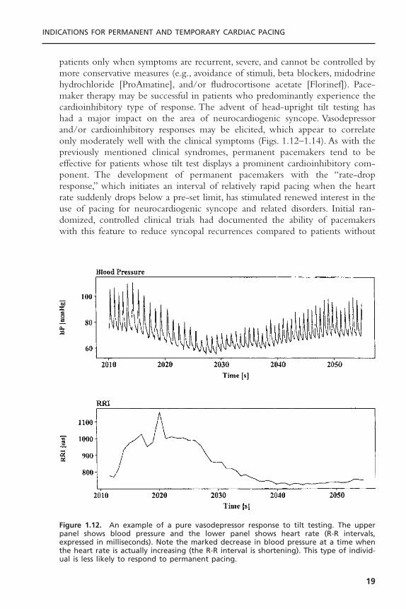
Figure 1.12. An example of a pure vasodepressor response to tilt testing. The upperpanel shows blood pressure and the lower panel shows heart rate (R-R intervals,expressed in milliseconds). Note the marked decrease in blood pressure at a time whenthe heart rate is actually increasing (the R-R interval is shortening). This type of individ-ual is less likely to respond to permanent pacing.
pacemakers.17,18 However, a recent double-blinded, randomized clinical trial(control group received pacemakers, but in ODO mode) showed only a trendtoward a reduction in frequency of syncope with active pacing without reach-ing statistical significance.19 The final role of pacing in prevention of neurocar-diogenic syncope is uncertain; at present, pacing is only used in truly refractorycases in which a significant bradycardic component has been well demonstrated.
One variant of neurally mediated syncope is the hypersensitive carotid sinussyndrome. A mildly abnormal response to vigorous carotid sinus massage mayoccur in up to 25% of patients, especially if coexisting vascular disease is present.Some patients with an abnormal response to carotid sinus massage may have nosymptoms suggestive of carotid sinus syncope. On the other hand, the typicalhistory of syncope—blurred vision and lightheadedness or confusion in thestanding or sitting position, especially during movement of the head or neck—should be suggestive of this entity. Classic triggers of carotid sinus syncope arehead turning, tight neckwear, shaving, and neck hyperextension. Syncopalepisodes usually last only several minutes and are generally reproducible in agiven patient. Symptoms associated with this syndrome may wax or wane overseveral years. Carotid sinus hypersensitivity is most often predominantly car-dioinhibitory in nature so that permanent pacing may be very helpful (Fig.
CARDIAC PACING AND ICDS
20
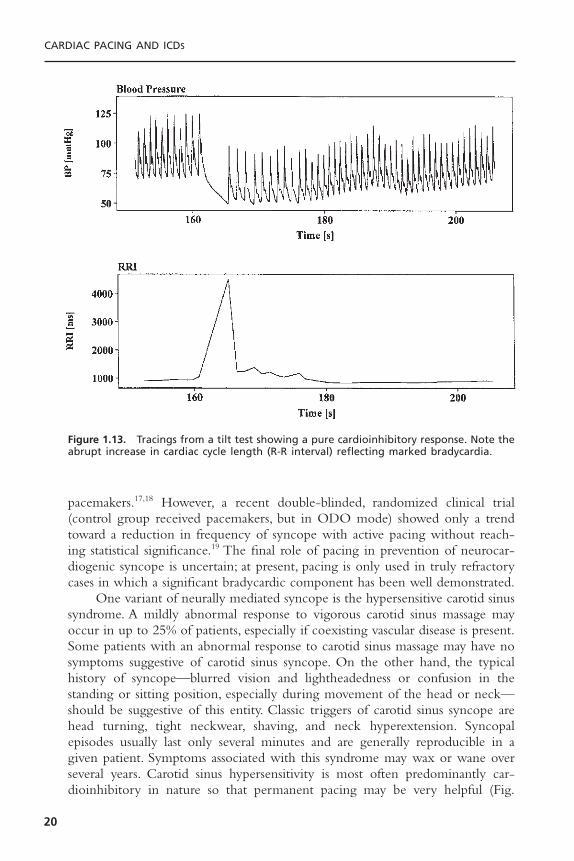
Figure 1.13. Tracings from a tilt test showing a pure cardioinhibitory response. Note theabrupt increase in cardiac cycle length (R-R interval) reflecting marked bradycardia.
1.15). In contrast, other forms of neurocardiogenic syncope often have a significant vasodepressor component, so that permanent pacing has a morelimited role.
The indications for pacemaker implantation in patients with neurally medi-ated syncope and hypersensitive carotid sinus syndrome are listed subsequently.
INDICATIONS FOR PERMANENT AND TEMPORARY CARDIAC PACING
21
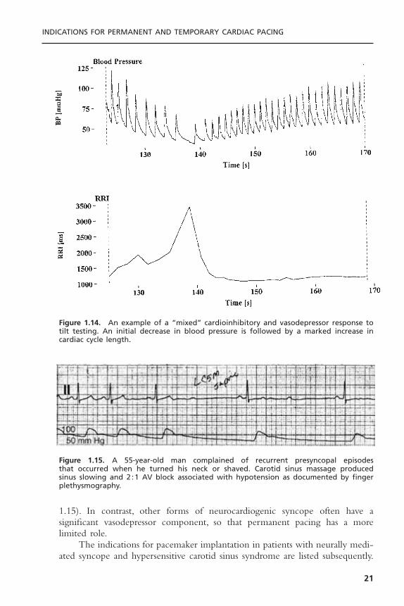
Figure 1.14. An example of a “mixed” cardioinhibitory and vasodepressor response totilt testing. An initial decrease in blood pressure is followed by a marked increase incardiac cycle length.
Figure 1.15. A 55-year-old man complained of recurrent presyncopal episodes that occurred when he turned his neck or shaved. Carotid sinus massage produced sinus slowing and 2 :1 AV block associated with hypotension as documented by fingerplethysmography.
Class I1. Recurrent syncope caused by carotid sinus stimulation; minimal carotid sinus
pressure induces ventricular asystole of more than 3-second duration in theabsence of any medication that depress the sinus node or AV conduction.(Level of evidence: C.)
Class IIa1. Recurrent syncope without clear, provocative events and with a hypersensi-
tive cardioinhibitory response. (Level of evidence: C.)2. Significantly symptomatic and recurrent neurocardiogenic syncope associated
with bradycardia documented spontaneously or at the time of tilt-tabletesting. (Level of evidence: C.)
Class III1. A hyperactive cardioinhibitory response to carotid sinus stimulation in
the absence of symptoms or in the presence of vague symptoms such as dizziness, lightheadedness, or both.
2. Recurrent syncope, lightheadedness, or dizziness in the absence of a hyper-active cardioinhibitory response.
3. Situational vasovagal syncope in which avoidance behavior is effective.
Idiopathic orthostatic hypotension is a related neurocirculatory disorderthat may respond to permanent pacing. Several reports have documented a ben-eficial response to atrial or AV sequential pacing in a small number of patientswith idiopathic orthostatic hypotension refractory to salt and steroid therapy.20
The rationale for pacing in this condition is that by increasing the paced rate(the lower rate in these series varies from 80 to 100 beats per minute), thecardiac output increases and potentially leads to more vasoconstriction. Thistherapy usually results in some clinical improvement, but it varies considerablyfrom patient to patient. There are currently no class I or class II indications forpermanent pacing for idiopathic orthostatic hypotension.
Hypertrophic CardiomyopathyHypertrophic cardiomyopathy is a disorder of the myocardium characterized byexcessive myocardial hypertrophy, with a predilection for the interventricularseptum. Although there may be obstructive (i.e., a demonstrable gradient acrossthe left ventricular outflow tract) and nonobstructive forms, there might be little difference between them because the gradient is dynamic and affected bypreload, afterload, and other factors. Difficulty with diastolic relaxation (and ven-tricular filling) of the thickened and noncompliant ventricular musculature ispresent in both forms of this disorder and may be an important determinant ofthe clinical presentation. Pacing is thought to exert a beneficial effect by inducing paradoxical septal motion and ventricular dyssynchrony and dilatation,thereby improving ventricular filling and reducing the outflow tract gradient.
CARDIAC PACING AND ICDS
22
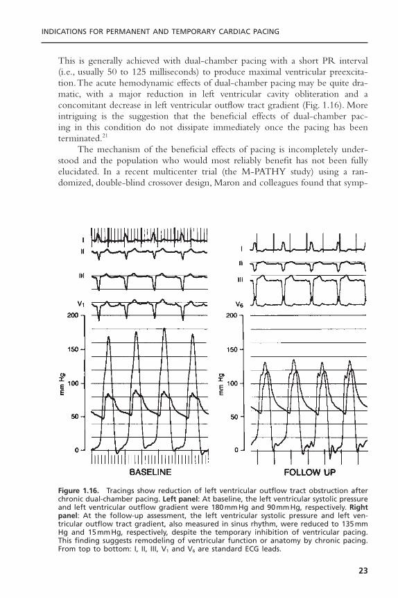
This is generally achieved with dual-chamber pacing with a short PR interval(i.e., usually 50 to 125 milliseconds) to produce maximal ventricular preexcita-tion.The acute hemodynamic effects of dual-chamber pacing may be quite dra-matic, with a major reduction in left ventricular cavity obliteration and aconcomitant decrease in left ventricular outflow tract gradient (Fig. 1.16). Moreintriguing is the suggestion that the beneficial effects of dual-chamber pac-ing in this condition do not dissipate immediately once the pacing has beenterminated.21
The mechanism of the beneficial effects of pacing is incompletely under-stood and the population who would most reliably benefit has not been fullyelucidated. In a recent multicenter trial (the M-PATHY study) using a ran-domized, double-blind crossover design, Maron and colleagues found that symp-
INDICATIONS FOR PERMANENT AND TEMPORARY CARDIAC PACING
23
Figure 1.16. Tracings show reduction of left ventricular outflow tract obstruction afterchronic dual-chamber pacing. Left panel: At baseline, the left ventricular systolic pressureand left ventricular outflow gradient were 180mmHg and 90mmHg, respectively. Rightpanel: At the follow-up assessment, the left ventricular systolic pressure and left ven-tricular outflow tract gradient, also measured in sinus rhythm, were reduced to 135mmHg and 15mmHg, respectively, despite the temporary inhibition of ventricular pacing.This finding suggests remodeling of ventricular function or anatomy by chronic pacing.From top to bottom: I, II, III, V1 and V6 are standard ECG leads.
tomatic improvement (quality of life and functional class) was not necessarilyaccompanied by improvement in objective indices such as treadmill exercise timeand peak oxygen consumption.22 Similarly, in the Pacing in Cardiomyopathy(PIC) study, Linde and colleagues found significant improvement in both theactive pacing and inactive pacing (placebo) group, although the improvementwas greater in those assigned to active pacing.23 These two studies suggest thatsome of the improvement seen in earlier studies may be partly due to placeboeffect or the known variability in clinical course of the disorder. Because pro-longation of life has not been documented with this therapy, the current roleof permanent pacemakers in hypertrophic cardiomyopathy is unclear. Accord-ingly, it should be remembered that surgical myotomy–myectomy is still con-sidered the gold standard for treatment of this condition.24 Septal ethanolablation is an emerging therapy as well. The clinician managing these patientsmust determine if a device is to be implanted with a dual-chamber pacemakeror if a dual-chamber defibrillator is the most appropriate choice.
The indications for permanent pacing for hypertrophic cardiomyopathy areas follows:
Class I1. Class I indications for sinus node dysfunction or AV block as previously
described. (Level of evidence: C.)
Class IIb1. Medically refractory, symptomatic hypertrophic cardiomyopathy with signif-
icant resting or provoked LV outflow tract obstruction. (Level of evidence:A.)
Class III1. Patients who are asymptomatic or medically controlled.2. Symptomatic patients without evidence of LV outflow tract obstruction.
Dilated Cardiomyopathy (Left Ventricular Systolic Dysfunction)A related area in which permanent pacing may be of benefit is dilated car-diomyopathy. Early studies have suggested that dual-chamber pacing, especiallywith a short AV delay, may have important hemodynamic benefit in patientswith severe congestive heart failure.25 Although the exact mechanism was notdetermined, it was postulated that the improvement in hemodynamics may berelated to optimization of ventricular filling or reduction of diastolic mitralregurgitation.26 However, in more recent controlled studies, other groups havefailed to confirm these beneficial effects.27 Studies of right ventricular outflowtract pacing for left ventricular systolic dysfunction have been negative ormixed.28
In contrast, there is now considerable evidence that the use of left ven-tricular or biventricular permanent pacing improves hemodynamics in certainpatients with congestive heart failure. Because left ventricular contraction is a
CARDIAC PACING AND ICDS
24

key determinant of cardiac output, in theory the properly synchronized contraction of the left ventricle or both ventricles should enhance cardiac performance in patients with intrinsic prolongation of the QRS duration.Randomized, double blinded, controlled clinical trials have clearly establishedthe beneficial role of biventricular pacing therapy in advanced heart failurepatients with prolonged QRS duration.29
The indications for pacing in patients with heart failure and impaired leftventricular systolic function are:
Class I1. Class I indications for sinus node dysfunction or AV block as previously
described. (Level of evidence: C.)
Class IIa1. Biventricular pacing in medically refractory, symptomatic NYHA class III or
IV patients with idiopathic dilated or ischemic cardiomyopathy, prolongedQRS interval (≥130 milliseconds), LV end-diastolic diameter ≥55mm andejection fraction £35%. (Level of evidence: A.)
Class III1. Asymptomatic dilated cardiomyopathy.2. Symptomatic dilated cardiomyopathy when patients are rendered asymp-
tomatic by drug therapy.3. Symptomatic ischemic cardiomyopathy when the ischemia is amenable to
intervention.
Prevention and Termination of Tachyarrhythmias Including the Prolonged QT Syndrome
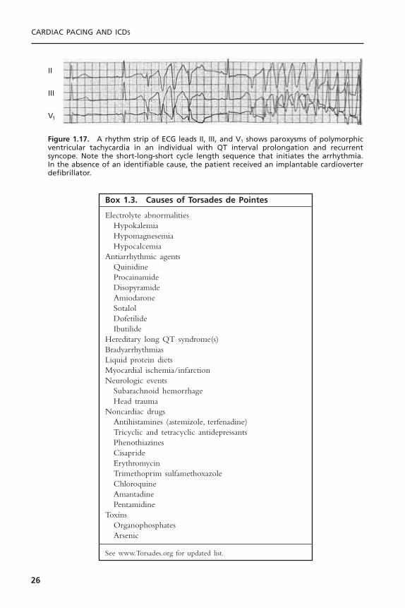
Permanent pacing can be used in some situations to prevent or terminatesupraventricular (supraventricular tachycardia [SVT]) and ventricular arrhyth-mias. Individuals with prolongation of the QT or QT-U interval may be proneto a type of polymorphic ventricular tachycardia known as torsades de pointes(Fig. 1.17).Tachycardia is often preceded by a short-long-short series of changesin cycle length. Episodes tend to be paroxysmal, recurrent, and may becomelife-threatening.Therefore, it is critical that the clinical syndrome be recognized,any offending drugs be stopped, and any electrolyte deficiencies be corrected.A summary of the various conditions associated with torsades de pointes is pro-vided in Box 1.3.
Permanent pacing may also be of help in patients with the long QT syn-drome, especially for bradycardic patients who have a history of ventriculararrhythmias or syncope. It provides more uniform repolarization and anincreased heart rate, which will shorten the QT interval.30 Permanent pacingmay also permit the use of beta blockers, known to be of benefit in this syn-drome, without worsening the resting bradycardia. The potential benefit of animplantable defibrillator should be considered in these patients.
INDICATIONS FOR PERMANENT AND TEMPORARY CARDIAC PACING
25
CARDIAC PACING AND ICDS
26
II
III
V1
Figure 1.17. A rhythm strip of ECG leads II, III, and V1 shows paroxysms of polymorphicventricular tachycardia in an individual with QT interval prolongation and recurrentsyncope. Note the short-long-short cycle length sequence that initiates the arrhythmia.In the absence of an identifiable cause, the patient received an implantable cardioverterdefibrillator.
Box 1.3. Causes of Torsades de Pointes
Electrolyte abnormalitiesHypokalemiaHypomagnesemiaHypocalcemia
Antiarrhythmic agentsQuinidineProcainamideDisopyramideAmiodaroneSotalolDofetilideIbutilide
Hereditary long QT syndrome(s)BradyarrhythmiasLiquid protein dietsMyocardial ischemia/infarctionNeurologic events
Subarachnoid hemorrhageHead trauma
Noncardiac drugsAntihistamines (astemizole, terfenadine)Tricyclic and tetracyclic antidepressantsPhenothiazinesCisaprideErythromycinTrimethoprim sulfamethoxazoleChloroquineAmantadinePentamidine
ToxinsOrganophosphatesArsenic
See www.Torsades.org for updated list.
Because radiofrequency ablation successfully treats most common reentrantSVT arrhythmias, antitachycardia pacing is now rarely used for these arrhyth-mias.There is, however, growing interest in permanent pacing therapies for atrialfibrillation. In patients with concomitant sinus bradycardia, dual-site atrial pacingcombined with drug therapy may reduce the recurrence rates of atrial fibrilla-tion.31 In addition, preliminary data suggest that antitachycardia pacing may ter-minate atrial fibrillation and atrial tachycardias in some patients.32 Ventricularantitachycardia pacing without back-up defibrillation is contraindicated due tothe risk of tachycardia acceleration.
The indications for permanent pacing to prevent or terminate tachycardiasare:
Class I1. Sustained pause-dependent VT, with or without prolonged QT, in which the
efficacy of pacing is thoroughly documented. (Level of evidence: C.)
Class IIa1. High-risk patients with congenital long-QT syndrome. (Level of evidence:
C.)2. Symptomatic recurrent SVT that is reproducibly terminated by pacing in the
unlikely event that catheter ablation and/or drugs fail to control the arrhyth-mia or produce intolerable side effects. (Level of evidence: C.)
Class IIb1. Recurrent SVT or atrial flutter that is reproducibly terminated by pacing as
an alternative to drug therapy or ablation. (Level of evidence: C.)2. AV reentrant or AV node-reentrant supraventricular tachycardia not respon-
sive to medical or ablative therapy. (Level of evidence: C.)3. Prevention of symptomatic, drug-refractory recurrent atrial fibrillation
in patients with co-existing sinus node dysfunction. (Level of evidence:B.)
Class III1. Tachycardias frequently accelerated or converted to fibrillation by pac-
ing.2. The presence of accessory pathways with the capacity for rapid anterograde
conduction whether or not the pathways participate in the mechanism ofthe tachycardia.
3. Frequent or complex ventricular ectopic activity without sustained VT in theabsence of the long-QT syndrome.
4. Torsades de pointes VT due to reversible causes.
Pacing for Children and Adolescents, Including Congenital Heart Block
The general indications for pacing in children and adolescents are similar tothose for adults with several additional considerations. The diagnosis of signifi-cant bradycardia in children depends on age, presence and type of congenital
INDICATIONS FOR PERMANENT AND TEMPORARY CARDIAC PACING
27
heart disease, and cardiac physiology. Following surgery for congenital heartdisease, patients may have postoperative AV block that if untreated by pacingwill worsen their prognosis.33 Congenital heart disease patients may also havetachycardia-bradycardia syndrome, but the benefits of pacing for this indicationare less clear. Congenital heart diseases such as corrected transposition of greatarteries, ostium primum atrial septal defects, and ventricular septal defects maybe associated with complete heart block.
Congenital complete AV block is a rare anomaly that results from abnor-mal embryonic development of the AV node and is not associated with struc-tural heart disease in 50% of cases. Congenital complete heart block is alsoassociated with maternal lupus erythematosus. Most of the children with iso-lated congenital complete AV block have a stable escape rhythm with a narrowcomplex. Pacing is generally indicated in children with complete heart block ifthe heart rate in the awake child is less than 50 beats per minute or if associ-ated with left ventricular systolic dysfunction or ventricular arrhythmias. Theindications for pacing in congenital complete AV block have been clarified bya prospective study demonstrating improved survival and reduced syncope,myocardial dysfunction, and mitral regurgitation even among asymptomaticpatients.34,35 Exercise testing does not predict future cardiac events in this pop-ulation.
The indications for permanent pacing in children and adolescents are:
Class I1. Advanced second- or third-degree AV block associated with symptomatic
bradycardia, ventricular dysfunction, or low cardiac output. (Level of evi-dence: C.)
2. Sinus node dysfunction with correlation of symptoms during age-inappro-priate bradycardia.The definition of bradycardia varies with the patient’s ageand expected heart rate. (Level of evidence: B.)
3. Postoperative advanced second- or third-degree AV block that is notexpected to resolve or persists at least 7 days after cardiac surgery. (Levels ofevidence: B, C.)
4. Congenital third-degree AV block with a wide QRS escape rhythm, complexventricular ectopy, or ventricular dysfunction. (Level of evidence: B.)
5. Congenital third-degree AV block in the infant with the ventricular rate less than 50 to 55 beats per minute or with congenital heart disease and a ventricular rate less than 70 beats per minute. (Levels of evidence:B, C.)
6. Sustained pause-dependent VT, with or without prolonged QT, in which theefficacy of pacing is thoroughly documented. (Level of evidence: B.)
Class IIa1. Bradycardia-tachycardia syndrome with the need for long-term antiarrhyth-
mic treatment other than digitalis. (Level of evidence: C.)2. Congenital third-degree AV block beyond the first year of life with
an average heart rate less than 50 beats per minute, abrupt pauses in ven-
CARDIAC PACING AND ICDS
28
tricular rate that are two or three times the basic cycle length, or associatedwith symptoms due to chronotropic incompetence. (Level of evidence: B.)
3. Long-QT syndrome with 2 :1 AV or third-degree AV block. (Level of evi-dence: B.)
4. Asymptomatic sinus bradycardia in the child with complex congenital heartdisease with resting heart rate less than 40 beats per minute or pauses in ven-tricular rate more than 3 seconds. (Level of evidence: C.)
5. Patients with congenital heart disease and impaired hemodynamics due tosinus bradycardia or loss of AV synchrony. (Level of evidence: C.)
Class IIb1. Transient postoperative third-degree AV block that reverts to sinus rhythm
with residual bifascicular block. (Level of evidence: C.)2. Congenital third-degree AV block in the asymptomatic infant, child, adoles-
cent, or young adult with an acceptable rate, narrow QRS complex, andnormal ventricular function. (Level of evidence: B.)
3. Asymptomatic sinus bradycardia in the adolescent with congenital heartdisease with resting heart rate less than 40 beats per minute or pauses in ven-tricular rate more than 3 seconds. (Level of evidence: C.)
4. Neuromuscular diseases with any degree of AV block (including first-degreeAV block), with or without symptoms, because there may be unpredictableprogression of AV conduction disease.
Class III1. Transient postoperative AV block with return of normal AV conduction.
(Level of evidence: B.)2. Asymptomatic postoperative bifascicular block with or without first-degree
AV block. (Level of evidence: C.)3. Asymptomatic type I second-degree AV block. (Level of evidence: C.)4. Asymptomatic sinus bradycardia in the adolescent with longest RR interval
less than 3 seconds and minimum heart rate more than 40 beats per minute.(Level of evidence: C.)
Orthotopic Cardiac TransplantationBradyarrhythmias following orthotopic cardiac transplantation are usually due tosinus node dysfunction, presumably secondary to surgical trauma to the donorsinus node or to interruption of its blood supply. The incidence of sinus nodedysfunction in this population is up to 23%, but there is a growing realizationthat the condition is often benign and reversible within 6 to 12 months aftertransplant.36
The indications for permanent pacing after orthotopic cardiac transplant are:
Class I1. Symptomatic bradyarrhythmias/chronotropic incompetence not expected to
resolve and other class I indications for permanent pacing. (Level of evidence:C.)
INDICATIONS FOR PERMANENT AND TEMPORARY CARDIAC PACING
29
Class IIb1. Symptomatic bradyarrhythmias/chronotropic incompetence that, although
transient, may persist for months and require intervention. (Level of evidence:C.)
Class III1. Asymptomatic bradyarrhythmias.
Permanent Pacing After the Acute Phase of Acute Myocardial Infarction
Bradyarrhythmias and conduction defects are relatively common after acutemyocardial infarction. In patients who have these problems, a decision aboutpermanent pacing must be made prior to the patient’s discharge from the hos-pital. It is important to realize that the indications for temporary pacing in thesetting of acute myocardial infarction are different from those for permanentpacing following infarction. Unfortunately, there is some uncertainty regardingpermanent pacing for these patients because large prospective controlled trialshave not been performed. In addition, the criteria for permanent pacing inpatients after a myocardial infarction do not necessarily require the presence ofsymptoms and the need for temporary pacing in the acute stages of infarctionis not by itself an indication for permanent pacing.
The prognosis for these patients is strongly influenced by the amount ofunderlying myocardial damage.37 In general, sinus node dysfunction tends to bebenign and reversible; and permanent pacemakers are rarely required. Similarly,second-degree and even third-degree AV block after inferior wall myocardialinfarction is usually reversible and rarely requires permanent pacing. In contrast,conduction defects after an anterior wall myocardial infarction usually warrantpermanent pacemaker insertion, although mortality remains extremely highbecause of pump failure (Fig. 1.18).
The indications for permanent pacing following acute myocardial infarc-tion are:
Class I1. Persistent second-degree AV block in the His-Purkinje system with bundle
branch block or third-degree AV block within or below the His-Purkinjesystem after acute myocardial infarction. (Level of evidence: B.)
2. Transient advanced (second- or third-degree) infranodal AV block and asso-ciated bundle-branch block. If the site of block is uncertain, an electrophys-iology study may be necessary. (Level of evidence: B.)
3. Persistent and symptomatic second- or third-degree AV block. (Level of evi-dence: C.)
Class IIb1. Persistent second- or third-degree AV block at the AV node level. (Level of
evidence: B)
CARDIAC PACING AND ICDS
30

Class III1. Transient AV block in the absence of intraventricular conduction defects.
(Level of evidence: B.)2. Transient AV block in the presence of isolated left anterior fascicular block.
(Level of evidence: B.)3. Acquired left anterior fascicular block in the absence of AV block. (Level of
evidence: B.)4. Persistent first-degree AV block in the presence of bundle-branch block that
is old or age indeterminate. (Level of evidence: B.)
Permanent Pacemaker Mode SelectionThe selection of a permanent pacing mode for any given patient is largely basedon the desire to maintain AV synchrony. Intuitively, the preservation of AV syn-chrony may seem desirable in all patients. However, the added cost and com-plexity of dual-chamber systems and the contradictory data concerning thebenefits of AV sequential pacing for some patient groups are all a basis for theongoing evaluation of the true advantages to dual-chamber pacing. It is gener-ally accepted that AV synchrony may benefit patients with left ventricular sys-tolic dysfunction, diastolic dysfunction, or heart failure by preserving the atrial
INDICATIONS FOR PERMANENT AND TEMPORARY CARDIAC PACING
31
Figure 1.18. A standard 12-lead ECG from an individual with a large anteroseptalmyocardial infarction complicated by congestive heart failure and right bundle branchblock with right axis deviation, presumably due to left posterior fascicular block. Thepatient developed transient high-degree AV block 72 hours after admission (a class I indi-cation) and subsequently underwent permanent pacemaker implantation.
contribution to ventricular filling. In patients with neurally mediated syncope,single-chamber atrial demand inhibited (AAI) or ventricular demand inhibited(VVI) pacing may not relieve symptoms because heart block or pacemaker syn-drome, respectively, may occur during pacing. AV sequential pacing is generallyaccepted in this situation as well. AAI pacing is reserved for patients who haveisolated sinus node dysfunction and no known or anticipated AV block. VVIpacing is indicated for patients with chronic atrial arrhythmias that are notexpected to return to sinus rhythm. Paroxysmal atrial arrhythmias are no longera contraindication to universal (DDD)pacing since the advent of mode switch-ing algorithms.
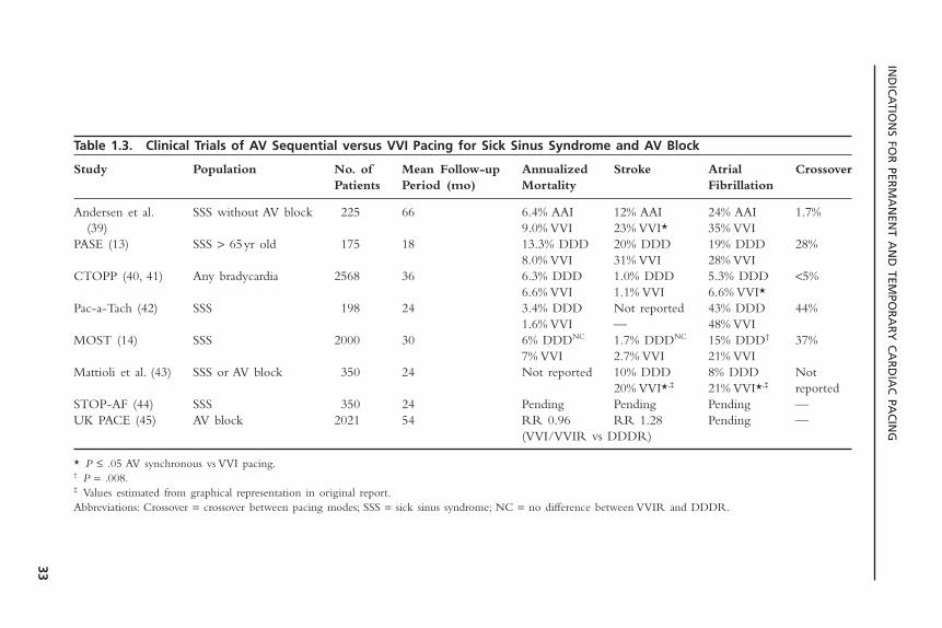
The optimal mode of pacing for sick sinus syndrome, the most commonindication for permanent pacing, is less clear. Numerous retrospective uncon-trolled studies have suggested that pacing to maintain AV synchrony (AAI/DDD)reduces stroke, atrial fibrillation, heart failure, and mortality when compared toVVI pacing.38 The current trends are to minimize the use of ventricular pacingeven in DDD mode because worsening heart failure and mortality may result.These findings have not been consistently validated in the randomized, con-trolled studies. The most recent studies to evaluate the benefits of AV sequen-tial versus VVI pacing in this population are listed in Table 1.3.13,14,39–45 It shouldbe noted that a high incidence of crossover from VVI to DDD pacing in moststudies may influence the results. Taken together, the present data suggest thatpacing to maintain AV synchrony in sick sinus syndrome does not affect mor-tality or the incidence of heart failure but does reduce atrial fibrillation andshows a trend toward reduced thromboembolism. Completion of long-termfollow-up (mean: 6.4 years) from the Canadian Trial of Physiologic Pacing(CTOPP) trial showed no difference between VVI and DDD pacing withrespect to cardiovascular death, stroke, or total mortality, but did show a persis-tent and significant relative risk reduction of 20% for the development of atrialfibrillation (decreased by physiologic pacing).40 The high incidence of pacemakersyndrome with VVI pacing also favors the use of DDD/AAI pacing in patientswith sick sinus syndrome, this incidence approaching 26% in one study (PASE).General guidelines for pacemaker mode selection are listed in Table 1.4, withthe caveat that most recommendations are based on current clinical practicerather than controlled clinical studies.
INDICATIONS FOR TEMPORARY CARDIAC PACINGThe following section reviews the clinical settings in which temporary cardiacpacing is indicated. Chapter 4 presents a review of the techniques and compli-cations of temporary cardiac pacing. A summary of the general indications fortemporary pacing is given in Box 1.4.
Acute Myocardial InfarctionIn the setting of an acute myocardial infarction, several different types of con-duction disturbances may become manifest.They include abnormalities of sinus
CARDIAC PACING AND ICDS
32
IND
ICA
TION
S FOR
PERM
AN
ENT A
ND
TEMPO
RA
RY
CA
RD
IAC
PAC
ING
33
Table 1.3. Clinical Trials of AV Sequential versus VVI Pacing for Sick Sinus Syndrome and AV Block
Study Population No. of Mean Follow-up Annualized Stroke Atrial CrossoverPatients Period (mo) Mortality Fibrillation
Andersen et al. SSS without AV block 225 66 6.4% AAI 12% AAI 24% AAI 1.7%(39) 9.0% VVI 23% VVI* 35% VVI
PASE (13) SSS > 65yr old 175 18 13.3% DDD 20% DDD 19% DDD 28%8.0% VVI 31% VVI 28% VVI
CTOPP (40, 41) Any bradycardia 2568 36 6.3% DDD 1.0% DDD 5.3% DDD <5%6.6% VVI 1.1% VVI 6.6% VVI*
Pac-a-Tach (42) SSS 198 24 3.4% DDD Not reported 43% DDD 44%1.6% VVI — 48% VVI
MOST (14) SSS 2000 30 6% DDDNC 1.7% DDDNC 15% DDD† 37%7% VVI 2.7% VVI 21% VVI
Mattioli et al. (43) SSS or AV block 350 24 Not reported 10% DDD 8% DDD Not20% VVI*,‡ 21% VVI*,‡ reported
STOP-AF (44) SSS 350 24 Pending Pending Pending —UK PACE (45) AV block 2021 54 RR 0.96 RR 1.28 Pending —
(VVI/VVIR vs DDDR)
* P £ .05 AV synchronous vs VVI pacing.† P = .008.‡ Values estimated from graphical representation in original report.Abbreviations: Crossover = crossover between pacing modes; SSS = sick sinus syndrome; NC = no difference between VVIR and DDDR.
CA
RD
IAC
PAC
ING
AN
D IC
DS
34
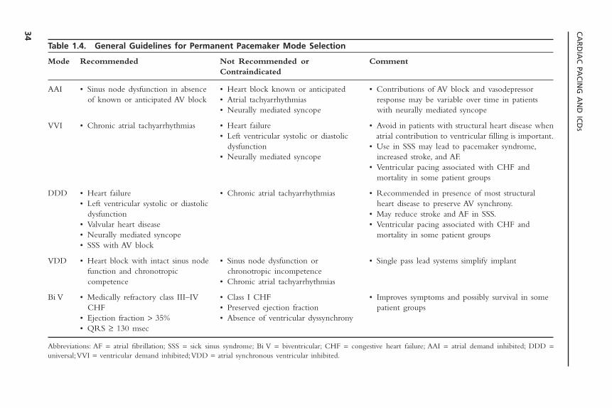
Table 1.4. General Guidelines for Permanent Pacemaker Mode Selection
Mode Recommended Not Recommended or CommentContraindicated
AAI • Sinus node dysfunction in absence • Heart block known or anticipated • Contributions of AV block and vasodepressorof known or anticipated AV block • Atrial tachyarrhythmias response may be variable over time in patients
• Neurally mediated syncope with neurally mediated syncope
VVI • Chronic atrial tachyarrhythmias • Heart failure • Avoid in patients with structural heart disease when• Left ventricular systolic or diastolic atrial contribution to ventricular filling is important.
dysfunction • Use in SSS may lead to pacemaker syndrome,• Neurally mediated syncope increased stroke, and AF.
• Ventricular pacing associated with CHF andmortality in some patient groups
DDD • Heart failure • Chronic atrial tachyarrhythmias • Recommended in presence of most structural• Left ventricular systolic or diastolic heart disease to preserve AV synchrony.
dysfunction • May reduce stroke and AF in SSS.• Valvular heart disease • Ventricular pacing associated with CHF and• Neurally mediated syncope mortality in some patient groups• SSS with AV block
VDD • Heart block with intact sinus node • Sinus node dysfunction or • Single pass lead systems simplify implantfunction and chronotropic chronotropic incompetencecompetence • Chronic atrial tachyarrhythmias
Bi V • Medically refractory class III–IV • Class I CHF • Improves symptoms and possibly survival in someCHF • Preserved ejection fraction patient groups
• Ejection fraction > 35% • Absence of ventricular dyssynchrony• QRS ≥ 130 msec
Abbreviations: AF = atrial fibrillation; SSS = sick sinus syndrome; Bi V = biventricular; CHF = congestive heart failure; AAI = atrial demand inhibited; DDD =universal;VVI = ventricular demand inhibited;VDD = atrial synchronous ventricular inhibited.
INDICATIONS FOR PERMANENT AND TEMPORARY CARDIAC PACING
35
impulse formation or conduction, disorders of atrioventricular conduction, anddisorders of intraventricular conduction. In general, any patient with brady-arrhythmias that are associated with symptoms or cause hemodynamic com-promise must be treated. The ways of identifying the patient populations atgreatest risk for the development of a significant bradyarrhythmia during acutemyocardial infarction and in whom temporary pacing should be performed pro-phylactically are discussed below. It is important to realize that the indicationsfor temporary pacing in the setting of acute myocardial infarction are differentfrom those for permanent pacing following infarction.
Sinus Node Abnormalities: Sinus node dysfunction may include sinus bradycar-dia, sinus arrest, and/or sinoatrial exit block. The incidence of these electrocar-diographic abnormalities is quite variable, ranging from 5% to 30% in differentseries.46 Abnormalities of sinus rhythm are more common, with inferoposterior
Box 1.4. Indications for Temporary Pacing
In Acute Myocardial InfarctionMedically refractory symptomatic sinus node dysfunctionMobitz II second-degree AV block with acute anterior infarctionThird-degree AV block with anterior infarctionNew bifascicular blockAlternating bundle branch blockAlternating Wenckebach blockNew bundle branch block with anterior infarctionBundle branch block of indeterminate age with anterior or indeterminate location
infarctMedically refractory AV block with bradycardia and symptoms regardless of infarct
locationIn Absence of Acute Myocardial Infarction
Medically refractory symptomatic bradycardia• sinus node dysfunction• second or third degree AV block
Third-degree AV block with wide QRS escape or ventricular rate <50bpmProphylactic
Swan-Ganz catheterization or endocardial biopsy in patient with left bundle branch block
Cardioversion in setting of sick sinus syndromeNew AV or bundle branch block with acute endocarditis (especially aortic valve
endocarditis)Perioperatively in patient with bifascicular block and history of syncopeTo allow pharmacologic treatment with drugs that worsen bradycardias
Treatment of TachyarrhythmiasTermination of recurrent ventricular or supraventricular tachycardiaSuppression of bradycardia-dependent ventricular tachyarrhythmias including torsades
de pointes

infarction because either the right or left circumflex coronary artery isoccluded—these arteries most commonly supply the sinus node.Another poten-tial reason is chemically mediated activation of receptors on the posterior leftventricular wall—these receptors are supplied by vagal afferent fibers.Treatmentof sinus bradycardia is not necessary, unless symptoms such as worsening myocar-dial ischemia, heart failure, or hypotension are documented. Atropine may beadministered for vagally mediated bradycardia. If bradycardia is prolonged andsevere, or is not responsive to atropine, temporary cardiac pacing is indicated.
Disorders of Atrioventricular Conduction: Atrioventricular block occurs withoutassociated intraventricular conduction system abnormalities in 12% to 25% ofpatients with acute myocardial infarction.47 The incidence of this findingdepends largely on the patient population and the site of infarction. First-degreeAV block occurs in 2% to 12% of patients, second-degree AV block in 3% to10% of patients, and third-degree AV block in 3% to 7% of patients.The major-ity of patients with abnormalities of atrioventricular conduction without bundlebranch block have evidence of an inferoposterior infarction (approximately70%). The reasons for the increased incidence of AV conduction abnormalitiesare related to the coronary blood supply to the AV node. The coronary arterysupplying the inferoposterior wall of the left ventricle is typically the right orleft circumflex coronary, which is occluded during an inferior infarction. Inaddition, activation of cardiac reflexes with augmentation of parasympathetictone during inferior ischemia (infarction) may also be responsible. In some cases,AV block may be due to release of adenosine caused by inferior ischemia orduring inferior infarction.48
The risk of progression from first-degree AV block to high-grade AV block(during inferior infarction) varies from 10% to 30%, and that of second-degreeAV block to complete heart block is approximately 35%. As would be expected,the development of high-grade AV block in the setting of acute inferoposteriorinfarction is usually associated with narrow QRS complex escape rhythms (Figs.1.19 and 1.20).The junctional escape rhythm usually remains stable at 50 to 60pulses per minute and can be increased by intravenous atropine, so even com-plete AV block may not require temporary pacing in this situation.
Type I second-degree AV block with a narrow QRS almost always repre-sents a conduction block in the AV node, and temporary cardiac pacing is rarelyrequired unless the patient has concomitant symptoms.Type I second-degree AVblock with a wide QRS complex may represent a conduction block in the AVnode or His bundle or contralateral bundle branch block. In these patients, espe-cially in the setting of anterior myocardial infarction, temporary prophylacticpacing must be considered. In patients with type II second-degree AV blockand a wide QRS complex in the setting of inferior infarction, or with a wideor narrow QRS complex during an anterior myocardial infarction, a temporarypacemaker should be inserted. Patients with a narrow QRS complex and typeII second-degree AV block in the setting of inferior infarction rarely progressto complete heart block.
CARDIAC PACING AND ICDS
36
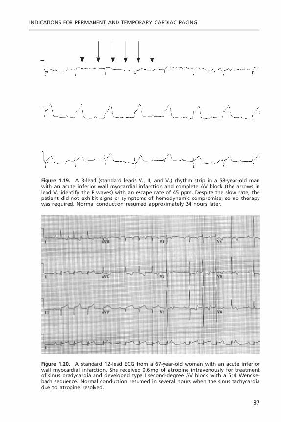
INDICATIONS FOR PERMANENT AND TEMPORARY CARDIAC PACING
37
Figure 1.19. A 3-lead (standard leads V1, II, and V5) rhythm strip in a 58-year-old manwith an acute inferior wall myocardial infarction and complete AV block (the arrows inlead V1 identify the P waves) with an escape rate of 45 ppm. Despite the slow rate, thepatient did not exhibit signs or symptoms of hemodynamic compromise, so no therapywas required. Normal conduction resumed approximately 24 hours later.
Figure 1.20. A standard 12-lead ECG from a 67-year-old woman with an acute inferiorwall myocardial infarction. She received 0.6mg of atropine intravenously for treatmentof sinus bradycardia and developed type I second-degree AV block with a 5 :4 Wencke-bach sequence. Normal conduction resumed in several hours when the sinus tachycardiadue to atropine resolved.
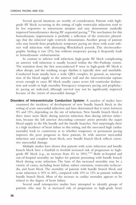
Several special situations are worthy of consideration. Patients with high-grade AV block occurring in the setting of right ventricular infarction tend tobe less responsive to intravenous atropine and may demonstrate markedlyimproved hemodynamics during AV sequential pacing.49 The mechanism for thishemodynamic improvement is probably a reflection of the restrictive physiol-ogy that the infarcted right ventricle demonstrates. Another group of patientswho may benefit from prophylactic temporary pacing are those with acute infe-rior wall infarction with alternating Wenckebach periods. This electrocardio-graphic finding is rare (2%), but without temporary pacing it frequently leadsto hemodynamic embarrassment.
In contrast to inferior wall infarction, high-grade AV block complicatingan anterior wall infarction is usually located within the His–Purkinje system.The transition from the first nonconducted P wave to high-grade AV block isoften abrupt, and the resulting escape rhythm is typically slow and unreliable.Conducted beats usually have a wide QRS complex. In general, an interrup-tion of the blood supply to the anterior wall and the interventricular septumsevere enough to cause AV block usually causes severe left ventricular dysfunc-tion and results in high mortality. Emergency temporary pacing and prophylac-tic pacing are indicated, although survival may not be significantly improvedbecause of the extent of myocardial damage.50
Disorders of Intraventricular Conduction System: A number of studies haveexamined the incidence of development of new bundle branch block in thesetting of acute myocardial infarction and have determined that it varies between5% and 15%, depending on the site of infarction. New bundle branch block isthree times more likely during anterior infarction than during inferior infarc-tion, because the left anterior descending coronary artery provides the majorblood supply to the His bundle and the bundle branches. Not surprisingly, thereis a high incidence of heart failure in this setting, and the associated high cardiacmortality leads to controversy as to whether temporary or permanent pacingimproves the poor prognosis in these patients. As with anterior myocardialinfarction and complete heart block, new bundle branch block reflects exten-sive myocardial damage.
Multiple studies have shown that patients with acute infarction and bundlebranch block have a fourfold to fivefold increased risk of progression to high-grade AV block (e.g., an increase from 4% to 18%).51,52 Both in-hospital andout-of-hospital mortality are higher for patients presenting with bundle branchblock during acute infarction. The basis of this increased mortality may be avariety of causes, including heart failure, infarct extension, ventricular tachycar-dia, and heart block. The mortality of patients with bundle branch block andacute infarction is 30% to 40%, compared with 10% to 15% in patients withoutbundle branch block. Most of the increase in cardiac mortality appears to berelated to the degree of heart failure.
Several small retrospective studies have attempted to identify groups ofpatients who may be at increased risk of progression to high-grade heart
CARDIAC PACING AND ICDS
38

block.51,52 Unfortunately, many of these studies are limited by their retrospec-tive nature, their small sample size, or their ascertainment bias. On the basis ofthe results of several studies, patients with conduction system abnormalities whoare recommended to have temporary pacemakers inserted prophylactically arelisted in Table 1.5.
Patients with a new bundle branch block and first-degree AV block or oldbifascicular block and first-degree AV block are at intermediate risk of pro-gression (19% to 29%) to high-grade AV block; they may undergo prophylac-tic pacing depending on the availability of facilities for emergency placementof a temporary pacemaker. Because the greatest risk of progression to completeheart block occurs in the first 5 days following infarction, these decisions shouldbe made promptly so that temporary pacing may be instituted.
The Multicenter Investigation of the Limitation of Infarct Size (MILIS)study suggested a simpler method of risk stratification.53 A “risk score” for thedevelopment of complete heart block was devised. Patients with any of the fol-lowing conduction disturbances were given one point: first-degree AV block,type I second-degree AV block, type II second-degree AV block, left anteriorfascicular block, left posterior fascicular block, right bundle branch block, andleft bundle branch block. The presence of no risk factors was associated with a1.2% risk of third-degree AV block, one risk factor with a 7.8% risk, two riskfactors with a 25% risk, and three risk factors with 36.4% risk of complete heartblock. These findings were validated by testing the risk score in over 3000patients from previously published studies.The risk score appears to be an alter-native to risk stratification using combinations of conduction disorders.
The effect of thrombolytic and early interventional therapies on the sub-sequent development of high-grade AV block in patients presenting with acuteinfarction and intraventricular conduction system disease has been poorlystudied. Although the incidence of complete AV block in acute myocardial
INDICATIONS FOR PERMANENT AND TEMPORARY CARDIAC PACING
39
Table 1.5. Risk of High-Grade AV Block during Acute Myocardial Infarction
Patient Group Risk of High-Grade AV Block
First-degree AV block and new bifascicular BBB 38–43%First-degree AV block and old bifascicular BBB 20–50%New bifascicular BBB 15–31%Alternating BBB 44%MILIS risk scorea
0 1.2%1 7.8%2 25%3 36.4%
a 1 point each for first-degree AV block, Mobitz I second-degree AV block, Mobitz II second-degreeAV block, left anterior fascicular block, left posterior fascicular block, right bundle branch block, leftbundle branch block.
infarctions has decreased following thrombolytic therapy, the mortality stillremains high.54
The most recent American Heart Association guidelines for temporarytransvenous pacing in the setting of acute myocardial infarction are55:
Class I1. Asystole2. Symptomatic bradycardia (includes sinus bradycardia with hypotension
and type I second-degree AV block with hypotension not responsive toatropine)
3. Bilateral bundle branch block (BBB; alternating BBB or right BBB [RBBB]with alternating left anterior fascicular block [LAFB]/left posterior fascicu-lar block [LPFB]) (any age)
4. New or indeterminate age bifascicular block (RBBB with LAFB or LPFB,or LBBB) with first-degree AV block
5. Mobitz type II second-degree AV block
Class IIa1. RBBB and LAFB or LPFB (new or indeterminate)2. RBBB with first-degree AV block3. LBBB, new or indeterminate4. Incessant ventricular tachycardia, for atrial or ventricular overdrive pacing5. Recurrent sinus pauses (greater than 3 seconds) not responsive to atropine
Class IIb1. Bifascicular block of indeterminate age2. New or age-indeterminate isolated RBBB
Class III1. First-degree heart block2. Type I second-degree AV block with normal hemodynamics3. Accelerated idioventricular rhythm4. BBB or fascicular block known to exist before acute myocardial infarction
PACING DURING CARDIAC CATHETERIZATIONDuring catheterization of the right side of the heart, manipulation of thecatheter may induce a transient RBBB in up to 10% of patients. This blockgenerally lasts for seconds or minutes but can occasionally last for hours or days.Trauma induced by right ventricular endomyocardial biopsy also may result intemporary, or rarely long-lasting, RBBB. This is a problem only in patients withpreexisting LBBB, in whom complete heart block may result.We therefore rec-ommend placement of a temporary transvenous pacing wire in patients who areundergoing right heart catheterization or biopsy in the presence of previouslyknown LBBB. Catheterization of the left side of the heart in patients withknown preexisting RBBB only rarely gives rise to complete heart block becauseof the short length of the left bundle branch. Significant bradycardia and asys-
CARDIAC PACING AND ICDS
40
tole can occur during injection of the right coronary artery. This complicationis extremely rare, and the placement of a temporary pacing catheter does notalter the morbidity or mortality of catheterization. The bradycardia usuallyresolves after several seconds. The same comments apply in general to place-ment of a temporary pacing wire during angioplasty.
PREOPERATIVE PACINGOne of the questions most frequently asked of a consulting cardiologist by bothsurgeons and anesthesiologists is whether it is necessary to insert a temporarypacing catheter in patients with bifascicular block undergoing general anesthe-sia. The results of several studies have shown that the incidence of intraopera-tive and perioperative complete heart block is quite low.There does not appearto be any benefit from preoperative prophylactic pacemaker insertion. Even inpatients with first-degree AV block and bifascicular block, there is a very lowincidence of perioperative high-grade heart block.
In patients who have bifascicular block and also type II second-degree AVblock or a history of unexplained syncope or presyncope; however, the risk ofdevelopment of high-grade AV block is higher, and a temporary pacemakershould be inserted. The appearance of new bifascicular block in the immediatepostoperative period should also lead to insertion of a temporary pacemaker andshould raise suspicion of an intraoperative myocardial infarction. The generalavailability of transcutaneous pacing may make it an acceptable alternative totemporary transvenous pacing in lower risk individuals, although poor patienttolerance is often a limitation.
Open-heart surgery tends to be associated with a somewhat higher inci-dence of postoperative bradyarrhythmias than does noncardiac surgery, due tothe direct trauma to the conduction system and interference with blood supply.Cardiac surgeons generally implant temporary epicardial pacing wires at the timeof surgery to facilitate temporary pacing. The major problem then becomesdetermining how long to wait for resumption of AV conduction and normal-ization of sinus node function before implanting a permanent pacemaker. Con-ventionally, a permanent pacemaker is recommended if the problem persistslonger than 5 to 7 days after the operation. Although normal conduction mayresume after this period of time, in the absence of definitive information aboutthe natural history of these disorders, permanent pacing seems to be a prudentchoice.
OTHER TEMPORARY PACINGTemporary pacing is indicated in patients with new AV or BBB in the settingof acute bacterial endocarditis. The development of a new conduction systemabnormality generally suggests that there is a perivalvular (ring) abscess that hasextended to involve the conduction system near the AV node and/or the Hisbundle.The endocarditis generally involves the non-coronary cusp of the aortic
INDICATIONS FOR PERMANENT AND TEMPORARY CARDIAC PACING
41

valve. In one study, high-grade or complete heart block developed in 22% ofpatients with aortic valve endocarditis and new first-degree AV block.56
Although these studies are retrospective, the patient with development of newAV block or BBB, especially in the setting of aortic valve endocarditis, shouldprobably undergo temporary pacing while cardiac evaluation continues.
Treatment of tumors of the head and/or neck or around the carotid sinusmay in some circumstances give rise to high-grade AV block.Temporary pacingmay be required during surgical treatment, radiation therapy, or chemotherapy.If the tumor responds poorly, permanent pacing may be necessary in some cases.The long-term risk for subsequent heart block due to tumor recurrence is dif-ficult to predict in some cases.
Lyme disease, a tickborne spirochete infection, causes a systemic infectionwith arthritis, skin lesions, myalgias, meningoencephalitis, and cardiac involve-ment in 5% to 10% of patients.57 Lyme disease is epidemic in the summermonths in the northeastern United States. Carditis typically occurs relatively late in the course of the illness, usually 4 to 8 weeks after the onset of symp-toms. AV block is the most common manifestation of carditis and tends to betransient. Block is most common at the level of the AV node and fluctuationbetween first-degree and higher degrees of AV block is frequent. Temporarycardiac pacing may be required, but the conduction disturbances usually resolve spontaneously, especially with antibiotic treatment, so permanent cardiacpacing rarely is necessary. Similar conduction disturbances can occasionally be seen in patients with viral myocarditis, as well as with other tickborne infections.
A number of medications may produce transient bradycardia that mayrequire temporary pacing until the drug has been stopped (see Box 1.2). Thesedrugs may cause sinus node dysfunction and/or AV block; if used in combina-tion, their effects may become more potent and exacerbate mild or latent con-duction system disease. If long-term therapy with these agents is necessary foran underlying disorder and a substitute cannot be found, permanent pacing maybe required.
Treatment of Tachycardias with Temporary PacingTemporary cardiac pacing has been used for the termination and/or preventionof a variety of arrhythmias. Pacing-termination of ventricular tachycardia is dis-cussed in detail in Chapter 8 on the implantable cardioverter defibrillator andwill not be dealt with here. Type I atrial flutter can be successfully pace-termi-nated approximately 65% of the time in an unselected population and in over90% of patients in whom atrial flutter develops after surgery.58 Due to the devel-opment of radiofrequency catheter ablation techniques, there is currently lessinterest in pace-termination of atrial flutter. Similarly, the most common vari-eties of paroxysmal supraventricular tachycardia are usually pace-terminable buttend to be equally amenable to radiofrequency ablation.
Torsades de pointes is a polymorphic ventricular tachycardia with a sinu-soidal electrocardiographic appearance, due to the QRS complex undulating
CARDIAC PACING AND ICDS
42

about the baseline. It results from prolongation and dispersion (inequality in dif-ferent parts of the ventricle) of myocardial repolarization, and is often reflectedon the surface ECG by a prolonged QT or QT-U interval. Episodes of tachy-cardia are often preceded by a short-long-short series of changes in cycle length.Importantly, episodes tend to be recurrent, paroxysmal, and nonsustained ini-tially, but may become sustained later unless the underlying condition is iden-tified and corrected. Therefore, it is critical that the clinical syndrome berecognized, any offending toxins or drugs be stopped, and any electrolyte defi-ciencies be corrected. (A summary of the causes of torsades de pointes is pro-vided in Table 1.3.) In some patients these treatments will be adequate; in somepatients, other forms of therapy must be considered. Overdrive atrial and/orventricular pacing may be effective in suppressing torsades de pointes becauseit provides more uniform repolarization and an increased heart rate, which willshorten the QT interval. Intravenous magnesium and also isoproterenol (whichalso increases heart rate and shortens repolarization) may also be effective insuppressing torsades de pointes, although the latter is associated with troublingside effects. For individuals who have recurrent symptoms refractory to con-ventional management, implantation of an implantable cardioverter defibrillatorshould be strongly considered.
REFERENCES
1. Schlant RC, Silverman ME. Anatomy of the heart. In: Hurst JW, ed.The Heart. 6thed. New York: McGraw-Hill, 1986:16–37.
2. Phibbs B, Friedman HS, Graboys TB, et al. Indications for pacing in the treatmentof bradyarrhythmias report of an independent study group. JAMA 1984;252:1307–1311.
3. Gregorators G, Abrams J, Epstein AE. ACC/AHA/NASPE 2002 Guideline updatefor Implantation of Cardiac Pacemakers and Antiarrhythmia Devices: SummaryArticle: A Report of the American Heart College of Cardiology/American HeartAssociation Task Force on Practice Guidelines (ACC/AHA/NASPE Committee toUpdate the 1998 Pacemaker Guidelines). Circulation 2002;106:2145–2161.
4. Dhingra RC, Denes P, Wu D, et al. Prospective observations in patients with chronicbundle branch block and H-V prolongation. Circulation 1976;53:600–604.
5. McAnulty JH, Rahimtoola SH, Murphy E, et al. Natural history of high risk bundlebranch block: final report of a prospective study. N Engl J Med 1982;307:137–143.
6. McAnulty JH, Rahimtoola SH. Bundle branch block. Prog Cardiovasc Dis1984;26:333–354.
7. Scheinman MM, Peters RW, Sauve MJ, et al.Value of the H-Q interval in patientswith bundle branch block and the role of prophylactic permanent pacing. Am JCardiol 1982;50:1316–1322.
8. Morady F, Higgins J, Peters RW, et al. Electrophysiological testing in bundle branch;block and unexplained syncope. Am J Cardiol 1984;54:587–591.
9. Salukhe TV, Francis DP, Sutton R. Comparison of medical therapy, pacing and defib-rillation in heart failure (COMPANION) trial terminated early; combined biven-
INDICATIONS FOR PERMANENT AND TEMPORARY CARDIAC PACING
43

tricular pacemaker-defibrillators reduce all-cause mortality and hospitalization. Int JCardiol 2003;87:119–120.
10. Barold SS.ACC/AHA guidelines for implantation of cardiac pacemakers: how accu-rate are the definitions of atrioventricular and intraventricular conduction blocks?Pacing Clin Electrophysiol 1993;16:1221–1226.
11. Sutton R, Kenny R. The natural history of sick syndrome. Pacing Clin Electro-physiol 1986;9:1110–1114.
12. Hilgard J, Ezri MD, Denes PB. Significance of the ventricular pauses of three secondsor more detected on 24-hour Holter recordings. Am J Cardiol 1985;55:1005–1008.
13. Lamas GA, Orav EJ, Stambler BS, et al. Quality of life and clinical outcomes inelderly patients treated with ventricular pacing as compared with dual-chamberpacing. N Engl J Med 1998;338:1097–1104.
14. Lamas GA, Kerry LE, Sweeny MO, et al.Ventricular pacing or dual cahmber pacingfor sinus node dysfunction. N Engl J Med 2002;346:1854–1862.
15. Morley CA, Sutton R. Carotid sinus syncope. Int J Cardiol 1984;6:287–293.16. Manolis AS, Linzer M, Estes NAM. Syncope: current diagnostic evaluation and man-
agement. Ann Intern Med 1990;112:850–863.17. Sheldon R, Koshman ML,Wilson W, Kieser T, Rose S. Effect of dual-chamber pacing
with automatic rate-drop sensing on recurrent neurally-mediated syncope. Am JCardiol 1998;81:158–162.
18. Connolly SJ, Sheldon R, Roberts RS, Gent M.Vasovagal Pacemaker Study Investi-gators. The North American Vasovagal Pacemaker Study (VPS): a randomized trialof permanent cardiac pacing for the prevention of vasovagal syncope. J Am CollCardiol 1999:3316–3320.
19. Connolly SJ, Sheldon R, Thorpe KE, et al. Pacemaker therapy for prevention ofsyncope in patients with recurrent severe vasovagal syncope: Second Vasovagal Pace-maker Study (VPS II): a randomized trial. JAMA 2003;289:2224–2229.
20. Weissmann P, Chin MT, Moss AJ. Cardiac tachypacing for severe refractory idio-pathic orthostatic hypotension. Ann Intern Med 1992;116:650.
21. Fananapazir L, Epstein ND, Curiel RV, et al. Long-term results of dual-chamber(DDD) pacing in hypertrophic cardiomyopathy: evidence for progressive symptom-atic and hemodynamic improvement and reduction of left ventricular hypertrophy.Circulation 1994;90:2731–2742.
22. Maron BJ, Nishimura RA, McKenna WJ, et al. For the M-PATHY Study Inves-tigators. Assessment of permanent dual-chamber pacing as a treatment for drug-refractory symptomatic patients with obstructive hypertrophic cardiomyopathy: arandomized double-blind crossover study. Circulation 1999;99:2927–2933.
23. Linde C, Gadler F, Kappenberger L, Ryden L, PIC Study Group. Placebo effect ofpacemaker implantation in obstructive hypertrophic cardiomyopathy. Am J Cardiol1999;83:903–907.
24. Maron BJ.Therapeutic strategies in hypertrophic cardiomyopathy: considerations andcritique of new treatment modalities. Heart Failure 1995;February/March:27–32.
25. Hochleitner M, Hortnagel H, Ng CK, et al. Usefulness of physiologic dual-chamberpacing in drug-resistant idiopathic dilated cardiomyopathy. Am J Cardiol 1990;66:198–202.
26. Nishimura RA, Hayes DL, Holmes DR Jr, Tajik AJ. Mechanism of hemodynamicimprovement by dual-chamber pacing for severe left ventricular dysfunction:
CARDIAC PACING AND ICDS
44
an acute Doppler and catheterization study. J Am Coll Cardiol 1995;25:281–288.
27. Gold MR, Feliciano Z, Gottlieb SS, Fisher ML. Dual-chamber pacing with a shortatrioventricular delay in congestive heart failure: a randomized study. J Am CollCardiol 1995;26:967–973.
28. Stambler BS, Ellenbogen K, Zhang X, et al. Right ventricular outflow versus apicalpacing in pacemaker patients with congestive heart failure and atrial fibrillation. JCardiovasc Electrophysiol 2003;14(11):1180–1186.
29. Abraham WT, Fisher WG, Smith AL, et al. Cardiac resynchronization in chronicheart failure. N Engl J Med 2002;346(24):1845–1853.
30. Moss AJ, Liu JE, Gottlieb SS, et al. Efficacy of permanent pacing in the management of high risk patients with long QT syndrome. Circulation 1991;84:1530.
31. Saksena S, Prakash A, Ziegler P, et al. Improved suppression of recurrent atrial fib-rillation with dual-site right atrial pacing and antiarrhythmic drug therapy. J AmColl Cardiol 2002;40(6):1140–1150.
32. Yung W, Brachmann J, Den Dulk K, et al. Initial clinical experience with a newarrhythmia management device. Circulation 1997;96:1–209.
33. Friedman RA. Congenital AV block. Pace me now or pace me later? Circulation1995;92:283–285.
34. Michaelsson M, Jonzon A, Riesenfeld T. Isolated congenital complete atrio-ventric-ular block in adult life. A prospective study. Circulation 1995;92:442–449.
35. Sholler GF,Walsh EP. Congenital complete heart block in patients without anatomicdefects. Am Heart J 1989;118:1193–1198.
36. Melton IC, Gilligan DM, Wood MA, Ellenbogen KA. Optimal cardiac pacing afterheart transplantation. Pacing Clin Electrophysiol 1999;22:1510–1527.
37. Simons GR, Sgarbosa E, Wagner G, et al. Atrioventricular and intraventricular con-duction disorders in acute myocardial infarction: a reappraisal in the thrombolyticera. Pacing Clin Electrophysiol 1998;21:2651–2661.
38. Tang CY, Kerr CR, Connally SJ. Clinical trials of pacing mode selection. CardiolClin 2000;18:1–23.
39. Andersen HR, Nielsen JC, Thompsen PE, et al. Long-term follow-up of patientsfrom a randomized trial of atrial versus ventricular pacing for sick-sinus syndrome.Lancet 1997;350:1210–1216.
40. Kerr CR, Connolly SJ, Abdollah H, et al. Canadian Trial of Physiological Pacing.Effects of physiological pacing during long-term follow-up. Circulation 2004;109:357–362.
41. Connolly SJ, Kerr CR, Gent RS, et al. Effects of physiologic pacing versus ven-tricular pacing on the risk of stroke and death due to cardiovascular cause. N EnglJ Med 2000;342:1385–1391.
42. Wharton JM, Sorrentino RA, Campbell P, et al. Effects of pacing modality on atrial tachyarrhythmia recurrence in the tachycardia-bradycardia syndrome: prelimi-nary results of the Pacemaker Atrial Tachycardia Trial. Circulation 1998;98:1–494.
43. Mattioli AV, Castellane ET,Vivoli D, et al. Prevalence of atrial fibrillation and strokein paced patients without prior atrial fibrillation: a prospective study. Clin Cardiol1998;21:117–122.
44. Charles RG, McComb JM. Systematic trial of pacing to prevent atrial fibrillation(STOP-AF). Heart 1997;78:224–225.
INDICATIONS FOR PERMANENT AND TEMPORARY CARDIAC PACING
45
45. Specialized ECG test may lead to fewer people receiving heart-shocking implants.Available at: http://www.acc.org/media/session_info/late/ACC03/lbct_monday.htm.Accessed September 14, 2004.
46. Parameswaran R, Phe T, Goldberg H. Sinus node dysfunction in acute myocardialinfarction. Br Heart J 1976;38:93–96.
47. DeGuzman M, Rahimtoola SH. What is the role of pacemakers in patients withcoronary artery disease and conduction abnormalities? Cardiovasc Clin 1983;13:191–201.
48. Wesley RC, Lerman BB, DiMarco JP, et al. Mechanism of atropine-resistant atri-oventricular block during inferior myocardial infarction; possible role of adenosine.J Am Coll Cardiol 1986;8:1232–1234.
49. Topol EJ, Goldschlager N, Ports TA, et al. Hemodynamic benefit of atrial pacing inright ventricular myocardial infarction. Ann Intern Med 1982;96:594–597.
50. Hauer RNW, Lie KI, Liem RL, Durrer D. Long-term prognosis in patients withbundle branch block complicating acute anteroseptal infarction. Am J Cardiol1982;49:1581–1585.
51. Hindman MC,Wagner GS, JaRo M, et al.The clinical significance of bundle branchblock complicating acute myocardial infarction. 1. Clinical characteristics, hospitalmortality, and one year follow up. Circulation 1978;58:679–688.
52. Hindman MC,Wagner GS, JaRo M, et al.The clinical significance of bundle branchblock complicating acute myocardial infarction. 2. Indications for temporary andpermanent pacemaker insertion. Circulation 1978;58:689–699.
53. Lamas GA, Muller JE,Turi ZG, et al. A simplified method to predict occurrence ofcomplete heart block during acute myocardial infarction. Am J Cardiol 1986;57:1213–1219.
54. Harpaz D, Behar S, Gottileb S, et al. Complete atrioventricular block complicatingacute myocardial infarction in the thrombolytic era. J Am Coll Cardiol 1999;34:1721–1728.
55. Ryan TJ, Antman EM, Brooks NH, et al. ACC/AHA guidelines for the manage-ment of patients with acute myocardial infarction: 1999 update: a report of theAmerican College of Cardiology/American Heart Association Task Force on Prac-tice Guidelines (Committee on Management of Acute Myocardial Infarction). J AmColl Cardiol 1999;34(3):890–911.
56. Roberts NK, Somerville J. Pathological significance of electrocardiographic changesin aortic valve endocarditis. Br Heart J 1969;31:395–396.
57. Cox J, Krajden M. Cardiovascular manifestations of Lyme disease. Am Heart J1991;122:1449–1455.
58. Peters RW, Weiss DN, Carliner NH, et al. Overdrive pacing for atrial flutter. Am JCardiol 1994;74:1021–1023.
CARDIAC PACING AND ICDS
46
47
MYOCARDIAL STIMULATIONAn artificial electrical pacing stimulus excites cardiac tissue by the creation ofan electrical field at the interface of the stimulating electrode and the under-lying myocardium. Although a pacing stimulus can be applied to any portionof the body, a tissue response occurs only in cells that are excitable. For an arti-ficial polarizing pulse to induce a response in excitable tissue, the stimulus mustbe of sufficient amplitude and duration to initiate a self-regenerating wavefrontof action potentials that propagate away from the site of stimulation. Myocar-dial stimulation depends on an intact source of the electrical pulse (the pulsegenerator), a conductor between the source of the electrical pulse and the stim-ulating electrode (the lead conductor), an electrode for delivery of the pulse,and an area of myocardium that is excitable. In this section, the basic proper-ties of myocardial stimulation are reviewed in detail.
BASIC ELECTROPHYSIOLOGYThe property of biologic tissues such as nerve and muscle to respond to a stimulus with a response that is out of proportion to the strength of the stimulusis known as excitability.1 Excitable tissues are characterized by a separation ofcharge across the cell membrane that results in a resting transmembrane elec-trical potential. For cardiac myocytes, the concentration of Na+ ions outside thecell exceeds the concentration inside the cell. In contrast, the inside of the cellhas a 35-fold greater concentration of K+ ions than the outside of the cell.Theresting transmembrane potential is maintained by the high resistance to ion flow,which is an intrinsic property of the lipid bilayer of the cell membrane. Becausethere is a passive leak of ions through membrane-bound ion channels, the resting potential is further maintained by two active transport mechanisms thatexchange Na+ ions for K+ and Ca2+ ions.The Na+–K+ ATPase exchange “pump”extrudes three Na+ ions for every two K+ ions that are moved into the cell.TheNa+–Ca2+ transport mechanism exchanges three Na+ ions toward the outside of
2Basic Concepts of Pacing
G. Neal Kay
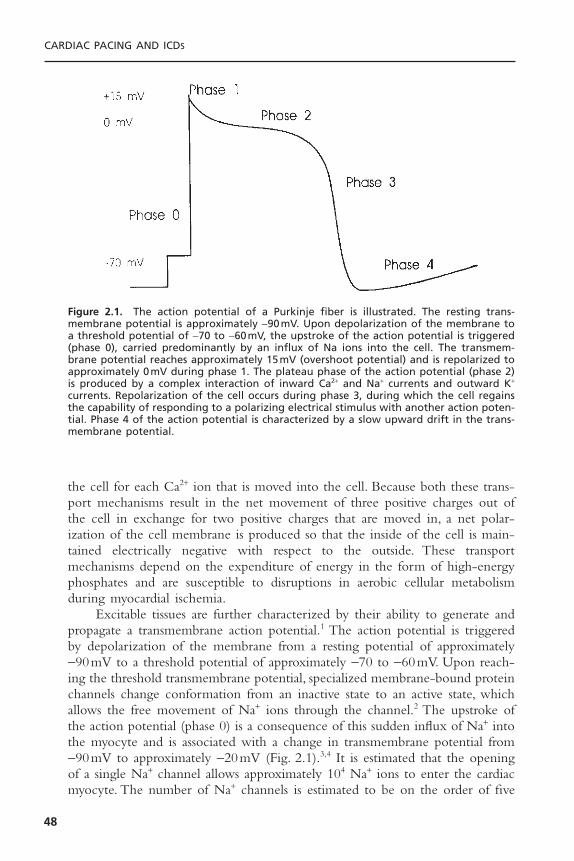
the cell for each Ca2+ ion that is moved into the cell. Because both these trans-port mechanisms result in the net movement of three positive charges out ofthe cell in exchange for two positive charges that are moved in, a net polar-ization of the cell membrane is produced so that the inside of the cell is main-tained electrically negative with respect to the outside. These transportmechanisms depend on the expenditure of energy in the form of high-energyphosphates and are susceptible to disruptions in aerobic cellular metabolismduring myocardial ischemia.
Excitable tissues are further characterized by their ability to generate andpropagate a transmembrane action potential.1 The action potential is triggeredby depolarization of the membrane from a resting potential of approximately -90mV to a threshold potential of approximately -70 to -60mV. Upon reach-ing the threshold transmembrane potential, specialized membrane-bound proteinchannels change conformation from an inactive state to an active state, whichallows the free movement of Na+ ions through the channel.2 The upstroke ofthe action potential (phase 0) is a consequence of this sudden influx of Na+ intothe myocyte and is associated with a change in transmembrane potential from-90mV to approximately -20mV (Fig. 2.1).3,4 It is estimated that the openingof a single Na+ channel allows approximately 104 Na+ ions to enter the cardiacmyocyte. The number of Na+ channels is estimated to be on the order of five
CARDIAC PACING AND ICDS
48
Figure 2.1. The action potential of a Purkinje fiber is illustrated. The resting trans-membrane potential is approximately -90mV. Upon depolarization of the membrane toa threshold potential of -70 to -60mV, the upstroke of the action potential is triggered(phase 0), carried predominantly by an influx of Na ions into the cell. The transmem-brane potential reaches approximately 15mV (overshoot potential) and is repolarized toapproximately 0mV during phase 1. The plateau phase of the action potential (phase 2)is produced by a complex interaction of inward Ca2+ and Na+ currents and outward K+
currents. Repolarization of the cell occurs during phase 3, during which the cell regainsthe capability of responding to a polarizing electrical stimulus with another action poten-tial. Phase 4 of the action potential is characterized by a slow upward drift in the trans-membrane potential.

to 10 channels per square micron of cell membrane.5,6 In addition to Na+ chan-nels, specialized proteins are also suspended in the membrane that have differ-ential selectivity for K+, Ca2+, and Cl- ions.7,8 The channels may remain in theopen configuration for less than 1 millisecond (characteristic of the Na+ channel)to hundreds of milliseconds (typical of K+ channels). The rapid upstroke of theaction potential is followed by a short period of hyperpolarization when thetransmembrane potential is transiently positively charged.The overshoot poten-tial is quickly abolished (phase 1) by a transient outward K+ current (Ito); andthe cell enters the plateau phase (phase 2), during which Ca2+ and Na+ are trig-gered to enter the cell and outwork K+ currents are activated.9,10 The cardiaccell is refractory to further electrical stimulation by a stimulus of any strengthduring the plateau phase. The net membrane voltage is maintained approxi-mately 0mV as the inward Na+ and Ca2+ currents are balanced by at least threeoutward K+ currents having different time constants (slow, rapid, and ultrarapid,IKS, IKR, and IKUR).These K+ currents have the property of delayed rectification.After the plateau phase, which lasts several hundred milliseconds, the cardiac cellbegins the process of repolarization as the outward currents exceed the inwardcurrents with regeneration of the resting membrane potential and the capabil-ity for responding to an electrical stimulus with another action potential (phase3).The repolarization phase is characterized by the continuation of outward K+
currents with inactivation of the inward Na+ and Ca2+ currents, which resultsin a net negative polarization of the inside of the cell. During the repolariza-tion phase an action potential may be induced if the myocyte is challenged byan electrical stimulus of sufficient strength. Following complete repolarizationof the membrane, the cell enters a diastolic period during which it is fullyexcitable (phase 4).11,12 Tissues demonstrating spontaneous automaticity exhibita gradual upward drift in transmembrane potential until threshold is reached.
The response of excitable membranes to electrical stimuli is an activeprocess that results in a response exceeding that of simple passive conductancealong the membrane. Gap junctions that provide low-resistance intercellularconnections conduct the action potential between myocytes.13,14 The actionpotential at the site of stimulation results in the depolarization of neighboringareas of the myocyte membrane to threshold voltage, which triggers the Na+
channels to open and results in regeneration of the action potential.The actionpotential is not only passively conducted but also actively regenerated at eachsegment of membrane. However, propagation of the action potential away fromthe site of electrical stimulation also depends on certain passive cable propertiesof the myocardium, including the axis of myofiber orientation and the geom-etry of the connections between fibers.15 For example, a wavefront of depolar-ization is conducted with a conduction velocity that is three to five times greateralong the longitudinal axis of a myofiber than along the transverse axis.16,17 Theseanisotropic conduction properties may be further exaggerated in the presenceof myocardial fibrosis in which the intercellular collagen matrix is increased withdecreased cell-to-cell communication. Such fibrosis is often present in patientswith disorders of the cardiac conduction system. In addition, the safety factor
BASIC CONCEPTS OF PACING
49

for successful propagation is greater at sites where sheets of myocardium ofsimilar size are joined than where a narrow isthmus of tissue joins a larger mass.18
Thus, as the structure of cardiac tissue is affected by pathologic conditions suchas fibrosis or infarction, the physiologic properties of conduction and excitabil-ity may be significantly altered.
STIMULATION THRESHOLDCardiac pacing involves the delivery of a polarizing electrical impulse from anelectrode in contact with the myocardium with the generation of an electricalfield of sufficient intensity to induce a propagating wave of cardiac action poten-tials.19 The stimulating pulse may be either anodal or cathodal in polarity,although with somewhat different stimulation characteristics. In addition, thestimulation characteristics are related to the source of the stimulating pulse, withconstant-voltage and constant-current generators exhibiting somewhat differentstimulation properties. The minimum stimulus intensity and duration necessaryto reliably initiate a propagated depolarizing wavefront from an electrode isdefined as the stimulation threshold. The stimulation threshold is a fundamen-tal concept that is crucial to programming and troubleshooting permanent pace-makers and pacing leads. In this section, the factors that determine stimulationthreshold will be discussed.20
Strength–Duration RelationFor a pacing stimulus to produce a self-regenerating wave of depolarization ina cardiac chamber (“capture”), the stimulus must exceed a critical amplitude(measured in volts or milliamperes) and must be applied for a sufficient dura-tion. These factors of stimulus amplitude and duration interact such that theminimal amplitude that is required to capture atrial or ventricular myocardiumdepends on the duration of the stimulating pulse (pulse duration).21–24 The stim-ulus amplitude for endocardial stimulation has an exponential relation to theduration of the pulse, with a rapidly rising strength–duration curve at pulse dura-tions less than 0.25 milliseconds and a relatively flat curve at pulse durationsgreater than 1.0 milliseconds (Fig. 2.2). As can be appreciated by examining thehyperbolic strength–duration curve, a small change in pulse duration is associ-ated with a significant change in the threshold amplitude at short pulse dura-tions; however, only a small change at longer pulse durations. Because of theexponential relationship between stimulus amplitude and pulse duration, theentire strength–duration curve can be described relatively accurately by twopoints on the curve, rheobase and chronaxie.21 Rheobase of a constant-voltage,strength–duration curve is defined as the least stimulus voltage that will elec-trically stimulate the myocardium at any pulse duration. For practical purposes,rheobase voltage is usually determined as the threshold stimulus voltage at apulse duration of 2.0 milliseconds. Pulse durations greater than 2.0 millisecondsprovide a negligible lowering of the threshold stimulus voltage. One exceptionto this rule is with field stimulation, such as with transcutaneous or trans-
CARDIAC PACING AND ICDS
50
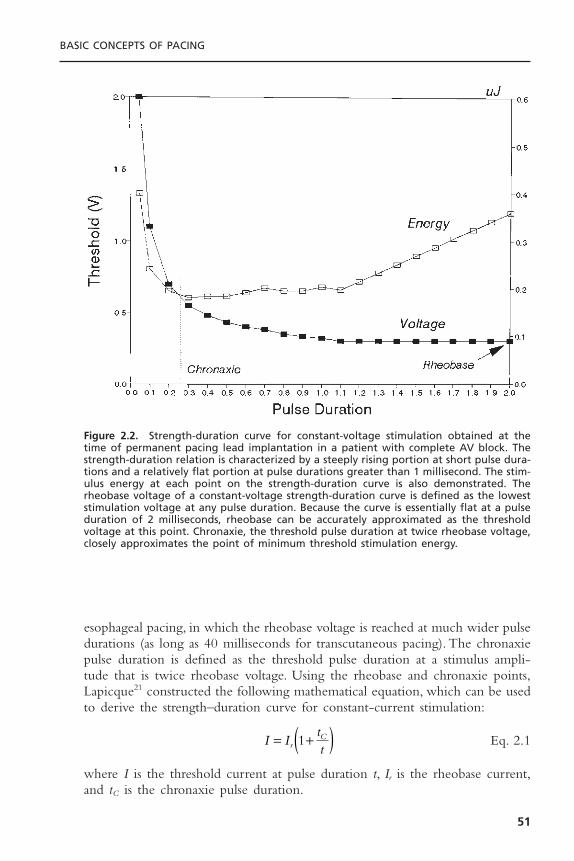
esophageal pacing, in which the rheobase voltage is reached at much wider pulsedurations (as long as 40 milliseconds for transcutaneous pacing). The chronaxiepulse duration is defined as the threshold pulse duration at a stimulus ampli-tude that is twice rheobase voltage. Using the rheobase and chronaxie points,Lapicque21 constructed the following mathematical equation, which can be usedto derive the strength–duration curve for constant-current stimulation:
Eq. 2.1
where I is the threshold current at pulse duration t, Ir is the rheobase current,and tC is the chronaxie pulse duration.
I IttrC= +( )1
BASIC CONCEPTS OF PACING
51
Figure 2.2. Strength-duration curve for constant-voltage stimulation obtained at thetime of permanent pacing lead implantation in a patient with complete AV block. Thestrength-duration relation is characterized by a steeply rising portion at short pulse dura-tions and a relatively flat portion at pulse durations greater than 1 millisecond. The stim-ulus energy at each point on the strength-duration curve is also demonstrated. Therheobase voltage of a constant-voltage strength-duration curve is defined as the loweststimulation voltage at any pulse duration. Because the curve is essentially flat at a pulseduration of 2 milliseconds, rheobase can be accurately approximated as the thresholdvoltage at this point. Chronaxie, the threshold pulse duration at twice rheobase voltage,closely approximates the point of minimum threshold stimulation energy.

The relation of stimulus voltage, current, and pulse duration to stimulusenergy is provided by the formula:
Eq. 2.2
where E is the stimulus energy, V is the stimulus voltage, R is the total pacingimpedance, and t is the pulse duration. The chronaxie pulse duration is impor-tant in the clinical application of pacing, as it approximates the point ofminimum threshold energy on the strength–duration curve.25,26 With pulse dura-tions greater than chronaxie, there is relatively little reduction in the thresholdvoltage. Rather, the wider pulse duration results in the wasting of stimulationenergy without providing a substantial increase in safety margin. At pulse dura-tions less than chronaxie there is a steep increase in threshold voltage and stim-ulation energy. As can be appreciated from Figure 2.2, the chronaxie pulseduration is usually close to the point of minimal stimulation energy. From theenergy equation (Eq. 2.2), note that, whereas the energy of a pacing stimulusincreases in direct relation to the pulse duration, the energy increases by thesquare of the voltage. Thus, doubling the stimulus voltage results in a fourfoldincrease in the stimulus energy.
An appreciation of the threshold strength–duration relation is importantfor the proper programming of stimulus amplitude and pulse duration. Modernpulse generators offer two major methods for evaluating the stimulation thresh-old: either automatic decrementation of the stimulus voltage at a constant pulseduration or automatic decrementation of the pulse duration at a constant stim-ulus voltage. To provide an adequate margin of safety, when the stimulationthreshold is determined by decrementing the stimulus amplitude, the stimulusvoltage is usually programmed to approximately twice the threshold value. Sim-ilarly, for pulse generators that determine threshold by automatically decre-menting pulse duration, the pulse duration is usually programmed to at leastthree times the threshold value. It should be recognized that the hyperbolicshape of the strength–duration curve has important implications for interpret-ing the results of threshold testing (Fig. 2.3). Although these methods providecomparable margins of safety when the threshold pulse duration is 0.15 mil-liseconds or less, tripling a threshold pulse duration that is greater than 0.3 mil-liseconds may not provide an adequate stimulation safety margin.
The threshold strength–duration curve is influenced by several factors,including the method of measurement, the nature of the electrode, the healthof the tissue in contact with the electrode, the distance between the electrodeand excitable myocardium, and the duration of lead implantation. Stimulationthresholds that are measured by decrementing stimulus voltage until loss ofcapture are usually 0.1 to 0.2V lower than when the stimulus intensity is grad-ually increased from subthreshold until capture is achieved.27,28 This empiricobservation, known as the Wedensky effect, must be considered when accuratemeasurements of stimulation threshold are required. The Wedensky effect maybe greater at narrow pulse durations, potentially reaching clinical significance.
EVRt
=2
CARDIAC PACING AND ICDS
52
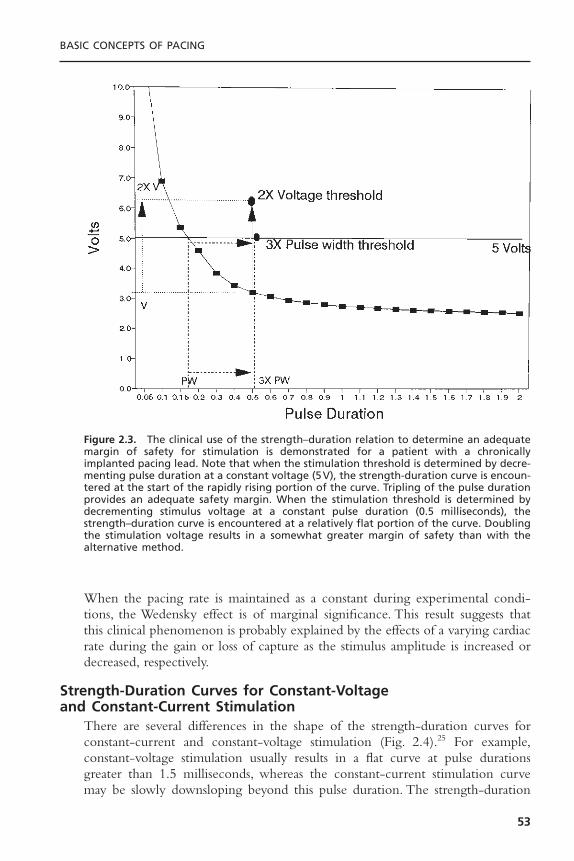
When the pacing rate is maintained as a constant during experimental condi-tions, the Wedensky effect is of marginal significance. This result suggests thatthis clinical phenomenon is probably explained by the effects of a varying cardiacrate during the gain or loss of capture as the stimulus amplitude is increased ordecreased, respectively.
Strength-Duration Curves for Constant-Voltage and Constant-Current Stimulation
There are several differences in the shape of the strength-duration curves forconstant-current and constant-voltage stimulation (Fig. 2.4).25 For example,constant-voltage stimulation usually results in a flat curve at pulse durationsgreater than 1.5 milliseconds, whereas the constant-current stimulation curvemay be slowly downsloping beyond this pulse duration. The strength-duration
BASIC CONCEPTS OF PACING
53
Figure 2.3. The clinical use of the strength–duration relation to determine an adequatemargin of safety for stimulation is demonstrated for a patient with a chronicallyimplanted pacing lead. Note that when the stimulation threshold is determined by decre-menting pulse duration at a constant voltage (5V), the strength-duration curve is encoun-tered at the start of the rapidly rising portion of the curve. Tripling of the pulse durationprovides an adequate safety margin. When the stimulation threshold is determined bydecrementing stimulus voltage at a constant pulse duration (0.5 milliseconds), thestrength–duration curve is encountered at a relatively flat portion of the curve. Doublingthe stimulation voltage results in a somewhat greater margin of safety than with thealternative method.

curve with constant-current stimulation increases more steeply at short pulsedurations than it does with constant voltage stimulation. Small changes in pulseduration less than 0.5 milliseconds may result in a significantly greater reduc-tion in stimulation safety margin for constant-current than for constant-voltagepulse generators. Because of this difference in the shape of the strength-duration curves, the chronaxie pulse duration of a constant-current strength-duration relation is significantly greater than that observed with constant-voltagestimulation. Because the most efficient pulse duration for electrical stimulationis at chronaxie (in terms of threshold energy), a constant-voltage pulse genera-tor can be set to deliver a narrower pulse duration than a constant-current gen-erator and yet provide the same safety margin. Virtually all permanentpacemakers presently in use are constant-voltage generators. In contrast, mosttemporary pacemakers use constant-current generators.
Time-Dependent Changes in Stimulation ThresholdMyocardial stimulation thresholds may change dramatically following position-ing of a permanent pacing lead.29–32 The typical course of events followingimplantation of an endocardial pacing lead starts with an acute rise in thresh-
CARDIAC PACING AND ICDS
54
Figure 2.4. Strength-duration curves determined with constant-current and constant-voltage stimulation in a single individual are demonstrated. Note that the constant-current stimulation curve continues to decline gradually at greater pulse durations thanthat obtained with constant-voltage stimulation.
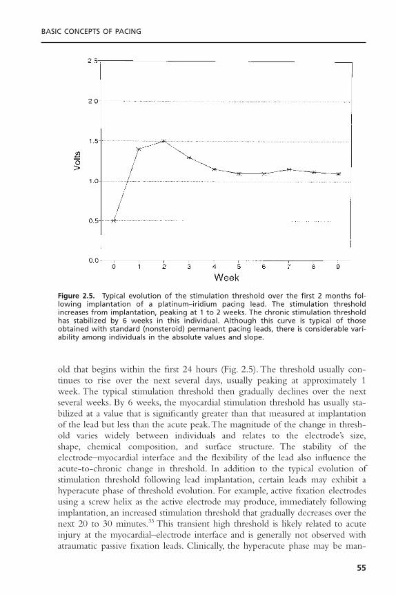
old that begins within the first 24 hours (Fig. 2.5). The threshold usually con-tinues to rise over the next several days, usually peaking at approximately 1week. The typical stimulation threshold then gradually declines over the nextseveral weeks. By 6 weeks, the myocardial stimulation threshold has usually sta-bilized at a value that is significantly greater than that measured at implantationof the lead but less than the acute peak.The magnitude of the change in thresh-old varies widely between individuals and relates to the electrode’s size,shape, chemical composition, and surface structure. The stability of the electrode–myocardial interface and the flexibility of the lead also influence theacute-to-chronic change in threshold. In addition to the typical evolution ofstimulation threshold following lead implantation, certain leads may exhibit ahyperacute phase of threshold evolution. For example, active fixation electrodesusing a screw helix as the active electrode may produce, immediately followingimplantation, an increased stimulation threshold that gradually decreases over thenext 20 to 30 minutes.33 This transient high threshold is likely related to acuteinjury at the myocardial–electrode interface and is generally not observed withatraumatic passive fixation leads. Clinically, the hyperacute phase may be man-
BASIC CONCEPTS OF PACING
55
Figure 2.5. Typical evolution of the stimulation threshold over the first 2 months fol-lowing implantation of a platinum–iridium pacing lead. The stimulation thresholdincreases from implantation, peaking at 1 to 2 weeks. The chronic stimulation thresholdhas stabilized by 6 weeks in this individual. Although this curve is typical of thoseobtained with standard (nonsteroid) permanent pacing leads, there is considerable vari-ability among individuals in the absolute values and slope.

ifested by a current of injury in the electrogram. Both the current of injury andthe stimulation threshold usually decline rapidly over the first several minutesbefore pursuing the typical acute-to-chronic threshold evolution, shown inFigure 2.5. Thus, comparisons of changes in stimulation threshold betweenvarying lead designs require an appreciation of the effects of the fixation mech-anism.The addition of steroid elution to a pacing electrode (or a steroid-elutingcollar around the electrode) markedly attenuates these evolutionary effects,resulting in a much more constant stimulation threshold over time. Several otherfactors may affect the change in stimulation threshold that occurs with lead mat-uration such as the mass of lead tip, the stability of the electrode in relation tothe myocardial interface, and the force with which the electrode is held incontact with the myocardium. In general, the more stable and the less traumaticthe interaction of the electrode and lead with the myocardium, the lower therise in threshold over time.
Proper programming of the stimulus amplitude of a permanent pacemakerrequires an understanding of several factors. First, the strength–duration relationmust be appreciated. Second, the safety margin that is chosen for a particularpatient must be based on the degree of pacemaker dependency—that is, thelikelihood of the patient’s developing symptoms should loss of effective pacingoccur. For patients judged to be highly pacemaker-dependent, a higher stimu-lation safety margin may be prudent. As an example, a patient with completeatrioventricular (AV) block with an unreliable ventricular escape rhythm maybe more likely to develop symptoms with loss of ventricular capture than is apatient with intermittent sinus node dysfunction. On the other hand, the patientwith AV block is likely to be less dependent on atrial than ventricular capture.Thus, a higher safety margin may be needed for the ventricular stimulus thanfor the atrial stimulus in such an individual.Third, an appreciation of the effectof stimulus amplitude and duration on battery longevity is required.As discussedlater in this chapter in the section on output circuits, programming the stimu-lus intensity greater than 2.8V results in a marked increase in current drain fromthe battery. Fourth, the overall metabolic and pharmacologic history of thepatient must be considered. For example, patients requiring the addition of anantiarrhythmic drug to their medication regimen may experience a smallincrease in pacing threshold. Similarly, patients subject to major shifts in potas-sium concentration or acid–base balance, such as those with renal failure, mayhave transient increases in pacing threshold.The safety margin that is chosen forthese individuals may need to be greater than that for other patients.
Several investigators have reported that pacing threshold varies inverselywith the surface area of the stimulating electrode.34–36 For spherical electrodes,the smaller the surface area of the electrode, the lower the pacing threshold.Theexplanation for this observation relates to the intensity of the electric field thatis generated at the surface of the electrode. For a constant-voltage pulse, thesmaller the electrode, the greater the intensity of the electric field and thecurrent density at the surface.The threshold maturation process has been shownto be caused by the growth of an inexcitable capsule of fibrous tissue sur-
CARDIAC PACING AND ICDS
56

rounding the electrode (Fig. 2.6).37,38 This fibrous capsule effectively increasesthe surface area of the electrode, thereby decreasing the intensity of the elec-tric field at the junction of the fibrous capsule and the more normal, excitablemyocardium.
The cellular events that result in the development of a fibrous capsule havebeen intensively studied.39,40 The initial tissue reaction to the implantation of apermanent pacing lead involves acute injury to cell membranes.This damage israpidly followed by the development of myocardial edema and coating of theelectrode by platelets and fibrin. These events are followed by the release ofchemotactic factors and the development of a typical cellular inflammatory reac-tion with the infiltration of polymorphonuclear leukocytes and mononuclearcells. Following the acute polymorphonuclear response, the myocardium at theinterface with the stimulating electrode is invaded by macrophages. The extra-cellular release of proteolytic enzymes and toxic-free oxygen radicals results inan acceleration of tissue injury underlying the electrode. The acute inflamma-tory response is followed by the accumulation of more macrophages and theinflux of fibroblasts into the myocardium. The fibroblasts in the myocardiumbegin producing collagen, leading to the development of the fibrotic capsulesurrounding the electrode.38
BASIC CONCEPTS OF PACING
57
Figure 2.6. Diagram of a fibrous capsule surrounding a chronically implanted pacingelectrode. The inexcitable capsule increases the effective radius of the stimulating elec-trode, reducing the current density at the interface of the capsule and excitable myo-cardium and increasing the stimulation threshold. (Courtesy of Medtronic, Inc.)
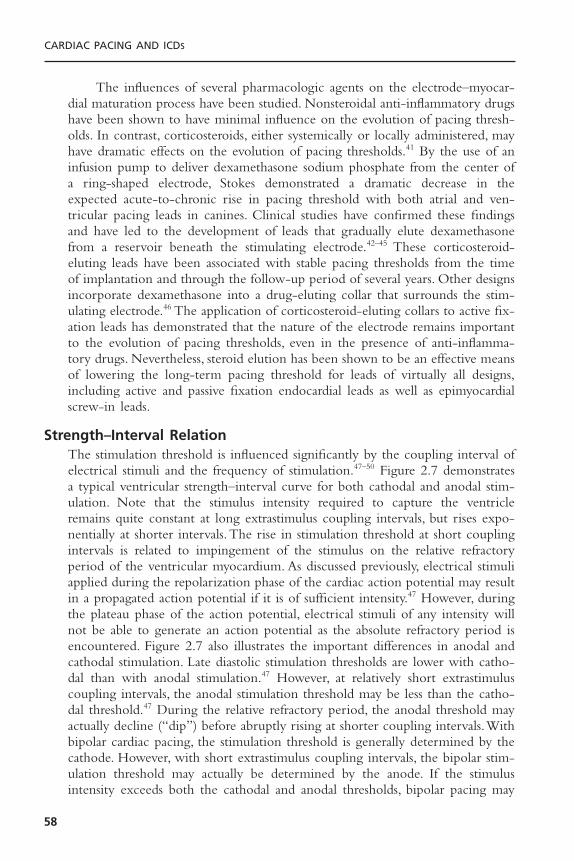
The influences of several pharmacologic agents on the electrode–myocar-dial maturation process have been studied. Nonsteroidal anti-inflammatory drugshave been shown to have minimal influence on the evolution of pacing thresh-olds. In contrast, corticosteroids, either systemically or locally administered, mayhave dramatic effects on the evolution of pacing thresholds.41 By the use of aninfusion pump to deliver dexamethasone sodium phosphate from the center ofa ring-shaped electrode, Stokes demonstrated a dramatic decrease in theexpected acute-to-chronic rise in pacing threshold with both atrial and ven-tricular pacing leads in canines. Clinical studies have confirmed these findingsand have led to the development of leads that gradually elute dexamethasonefrom a reservoir beneath the stimulating electrode.42–45 These corticosteroid-eluting leads have been associated with stable pacing thresholds from the timeof implantation and through the follow-up period of several years. Other designsincorporate dexamethasone into a drug-eluting collar that surrounds the stim-ulating electrode.46 The application of corticosteroid-eluting collars to active fix-ation leads has demonstrated that the nature of the electrode remains importantto the evolution of pacing thresholds, even in the presence of anti-inflamma-tory drugs. Nevertheless, steroid elution has been shown to be an effective meansof lowering the long-term pacing threshold for leads of virtually all designs,including active and passive fixation endocardial leads as well as epimyocardialscrew-in leads.
Strength–Interval RelationThe stimulation threshold is influenced significantly by the coupling interval ofelectrical stimuli and the frequency of stimulation.47–50 Figure 2.7 demonstratesa typical ventricular strength–interval curve for both cathodal and anodal stim-ulation. Note that the stimulus intensity required to capture the ventricleremains quite constant at long extrastimulus coupling intervals, but rises expo-nentially at shorter intervals.The rise in stimulation threshold at short couplingintervals is related to impingement of the stimulus on the relative refractoryperiod of the ventricular myocardium. As discussed previously, electrical stimuliapplied during the repolarization phase of the cardiac action potential may resultin a propagated action potential if it is of sufficient intensity.47 However, duringthe plateau phase of the action potential, electrical stimuli of any intensity willnot be able to generate an action potential as the absolute refractory period isencountered. Figure 2.7 also illustrates the important differences in anodal andcathodal stimulation. Late diastolic stimulation thresholds are lower with catho-dal than with anodal stimulation.47 However, at relatively short extrastimuluscoupling intervals, the anodal stimulation threshold may be less than the catho-dal threshold.47 During the relative refractory period, the anodal threshold mayactually decline (“dip”) before abruptly rising at shorter coupling intervals.Withbipolar cardiac pacing, the stimulation threshold is generally determined by thecathode. However, with short extrastimulus coupling intervals, the bipolar stim-ulation threshold may actually be determined by the anode. If the stimulusintensity exceeds both the cathodal and anodal thresholds, bipolar pacing may
CARDIAC PACING AND ICDS
58
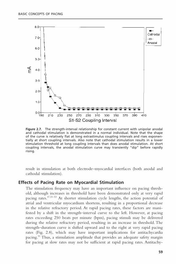
result in stimulation at both electrode–myocardial interfaces (both anodal andcathodal stimulation).
Effects of Pacing Rate on Myocardial StimulationThe stimulation frequency may have an important influence on pacing thresh-old, although increases in threshold have been demonstrated only at very rapidpacing rates.47,51–53 At shorter stimulation cycle lengths, the action potential ofatrial and ventricular myocardium shortens, resulting in a proportional decreasein the relative refractory period. At rapid pacing rates, these factors are mani-fested by a shift in the strength–interval curve to the left. However, at pacingrates exceeding 250 beats per minute (bpm), pacing stimuli may be deliveredduring the relative refractory period, resulting in an increase in threshold. Thestrength–duration curve is shifted upward and to the right at very rapid pacingrates (Fig. 2.8), which may have important implications for antitachycardiapacing.51 Thus, a stimulation amplitude that provides an adequate safety marginfor pacing at slow rates may not be sufficient at rapid pacing rates. Antitachy-
BASIC CONCEPTS OF PACING
59
Figure 2.7. The strength-interval relationship for constant current with unipolar anodaland cathodal stimulation is demonstrated in a normal individual. Note that the shape of the curve is relatively flat at long extrastimulus coupling intervals and rises exponen-tially at short coupling intervals. Also note that cathodal stimulation results in a lowerstimulation threshold at long coupling intervals than does anodal stimulation. At shortcoupling intervals, the anodal stimulation curve may transiently “dip” before rapidlyrising.

cardia devices provide for this possible increase in stimulation threshold by anautomatic increase in the amplitude of pacing stimuli that are delivered at rapidpacing rates. In recognition of the rate-dependence of the pacing threshold,implantable cardioverter-defibrillators typically provide a greater stimulus inten-sity during antitachycardia pacing than during antibradycardia pacing.
PHARMACOLOGIC AND METABOLIC EFFECTS ON STIMULATION THRESHOLD
The stimulation threshold may demonstrate considerable variability over thenormal 24-hour period, generally increasing during sleep and falling during thewaking hours.54,55 The changes in threshold parallel fluctuations in autonomictone and circulating catecholamines, and consequently there is a decreasedthreshold during exercise. The stimulation threshold is inversely related to thelevel of circulating corticosteroids. The stimulation threshold may increase fol-lowing eating, during hyperglycemia, hypoxemia, hypercarbia, and metabolic aci-dosis or alkalosis.56–60 The stimulation threshold may increase dramatically duringacute viral illnesses, especially in children. The concentration of serum elec-trolytes may also influence stimulation threshold. For instance, stimulationthreshold typically rises during hyperkalemia.57–59
CARDIAC PACING AND ICDS
60
Figure 2.8. The effect of pacing rate on the atrial strength–duration relation for anormal individual is demonstrated. Threshold curves were obtained at pacing rates of125 to 300ppm in increments of 25ppm. Note that the strength-duration curves largelyoverlap at pacing rates of 125 to 250ppm. At pacing rates of 275 to 300ppm, the curveis shifted upward and to the left.
Drugs may also influence stimulation threshold. As mentioned above, cat-echolamines reduce threshold, and the infusion of isoproterenol may restorecapture in some patients with exit block.55 In contrast, beta-blocking drugsincrease the stimulation threshold.61 Corticosteroids, either orally or parenterallyadministered, may produce a dramatic decrease in stimulation threshold and areoccasionally useful for the management of the acute increase in threshold thatmay be observed following lead implantation.41 The list of drugs that raise thestimulation threshold includes the type I antiarrhythmic drugs quinidine,62 pro-cainamide,63 flecainide,64 and encainide. It is not clear whether the type III drugamiodarone has similar effects.Virtually all antiarrhythmic drugs may influencethe pacing threshold, although they are usually clinically important only at highserum concentrations.
Occasional patients exhibit a progressive rise in stimulation threshold overtime, a clinical syndrome known as exit block. Exit block seems to occur despiteoptimal lead positioning, as it recurs with the subsequent implantation of newpacing leads. In patients with exit block, the threshold changes in the atriumtend to parallel those in the ventricle. Exit block is best managed by the use ofsteroid-eluting ventricular leads, which have been associated with low thresh-olds in patients with this syndrome (Fig. 2.9).42–45
BASIC CONCEPTS OF PACING
61
Figure 2.9. The evolution of stimulation threshold voltage (pulse duration 0.5 millisec-onds) in the right ventricular apex is demonstrated for an individual with a history of exit block. Note that the stimulation threshold increases progressively from implanta-tion with an active fixation ventricular lead (model 4058). Following implantation of acorticosteroid-eluting electrode (model 4004) in the same patient, the stimulation thresholdremains low. Exit block occurs infrequently but usually recurs with standard (nonsteroid)pacing leads.

IMPEDANCE
Impedance is the sum of all factors that oppose the flow of current in an elec-tric circuit. Impedance is not necessarily the same as resistance.The relationshipbetween voltage (V ), current (I ), and resistance (R) in an electrical circuit isestimated by Ohm’s law, V = IR. For circuits that follow Ohm’s law, impedanceand resistance are equal. If voltage is held constant, the current flow is inverselyrelated to the resistance of the circuit (I = V/R). The leading-edge voltage of aconstant-voltage pulse generator is fixed, and the lower the resistance, the greaterthe current flow. In contrast, the greater the resistance, the lower the currentflow. Because implantable pulse generators are powered by lithium iodine bat-teries with a fixed amount of charge, pacing impedance is an important deter-minant of battery longevity.
The total pacing impedance is determined by factors that are related tothe lead conductor (resistance), the resistance to current flow from the electrodeto the myocardium (electrode resistance), and the accumulation of charges ofopposite polarity in the myocardium at the electrode–tissue interface (polariza-tion).Thus, the total pacing impedance (Ztotal) = Zc Ze Zp, where Zc is the con-ductor resistance, Ze is the electrode resistance, and Zp is the polarizationimpedance.The resistance to current flow provided by the lead conductor resultsin a voltage drop across the lead with a portion of the pacing pulse convertedinto heat. Thus, this component of the total pacing impedance is an inefficientuse of electrical energy and does not contribute to myocardial stimulation.Theideal pacing lead would have a very low conductor resistance (Zc). In contrast,the ideal pacing lead would also have a relatively high electrode resistance (Ze)to minimize current flow and maximize battery life.65 The electrode resistanceis largely a function of the electrode radius, with higher resistance provided bya smaller electrode. An electrode with a small radius minimizes current flow inan efficient manner. In addition to providing a greater electrode resistance,pacing electrodes with a small radius provide increased current density and lowerstimulation thresholds. Because of these properties, newer pacing and implantablecardioverter-defibrillator (ICD) leads take advantage of smaller electrodes toincrease electrode resistance, allowing the total pacing impedance to exceed 1000 ohms. Compared with a standard pacing lead with a total impedance of500 ohms, a lead with 1000 ohms of impedance would decrease current drainof each pacing pulse by 50%, thereby prolonging the usable battery life of theimplantable pulse generator. The routine use of these leads will allow implantabledevices to become smaller while maintaining battery longevity.There is a prac-tical lower limit to the size of the electrode, which is related to the likelihoodof maintaining stable contact of the electrode with the endocardium through-out the cardiac and respiratory cycles. For example, pacing leads with a verysmall distal electrode may be associated with a relatively high pacing thresholdin a small proportion of patients (<5%), probably as a result of radiographi-cally imperceptible “microdislodgement” of the electrode as it contacts the endocardium.
CARDIAC PACING AND ICDS
62
The third component of pacing impedance, polarization impedance, is aneffect of electrical stimulation and is related to the movement of charged ionsin the myocardium toward the cathode. When an electrical current is appliedto the myocardium, the cathode attracts positively charged ions and repels neg-atively charged ions in the extracellular space.The cathode rapidly becomes sur-rounded by a layer of hydrated Na+ and H3O- ions. Farther away from thecathode, a second layer forms of negatively charged ions (Cl-, HPO4
2-, and OH-). Thus, the negatively charged cathode induces the accumulation of twolayers of oppositely charged ions in the myocardium. Initially, the movement ofcharged ions results in the flow of current in the myocardium. As the cathodebecomes surrounded by an inside layer of positive charges and an outside layerof negative charges, a functional capacitor develops that impedes the further move-ment of charge. The capacitive effect of polarization increases throughout theapplication of the pulse, peaking at the trailing edge and decaying exponentiallyfollowing the pulse as charged layers dissolve into electrical neutrality (Fig. 2.10).Because polarization impedes the movement of charge in the myocardium, it isinefficient and results in an increased voltage requirement for stimulation.Thus,polarization impedance reduces the effectiveness of a pacing stimulus to stimu-late the myocardium and wastes current. Polarization impedance is directlyrelated to the duration of the pulse and can be minimized by the use of rela-tively short pulse durations. Polarization is inversely related to the surface areaof the electrode.To minimize the effect of polarization (Zp) but maximize elec-trode resistance (Ze), the surface area of the electrode can be made large but thegeometric radius small by the use of a porous coating on the electrode.66–68 Elec-trodes constructed with activated carbon,69,70 or coated with platinum black71 oriridium oxide, are effective in minimizing the wasteful effects of polarizationand in diminishing afterpotentials, which can interfere with sensing.
The evolution of pacing impedance is usually characterized by a fall overthe first 1 to 2 weeks following implantation.32 The chronic pacing impedancethen rises to a stable value that is, on average, approximately 15% higher thanthat at implant. Serial measurements of pacing impedance are extremely valu-able for the assessment of lead integrity; low impedance measurements usuallyreflect a failure of conductor insulation, and high values often suggest conduc-tor fracture or a loose set-screw at the proximal connector. It should be empha-sized that the method of measurement greatly influences the impedance value.For example, if the pacing impedance is measured at the leading edge of thepulse, the value reflects Zc and Ze but not Zp. In contrast, measurements nearthe midpoint of the pulse are a more accurate reflection of total pacing imped-ance. For clinical purposes, serial assessments of impedance should use a consis-tent method of measurement.
BIPOLAR VERSUS UNIPOLAR STIMULATIONThe term unipolar pacing is technically a misnomer, as both bipolar and unipo-lar configurations require an anode and a cathode to complete the electrical
BASIC CONCEPTS OF PACING
63

circuit. Because both unipolar and bipolar pacing use an electrode in contactwith the myocardium (usually as the cathode), the difference in these configu-rations lies in the location of the other electrode (usually the anode). For aunipolar pacing stimulus, the anode is extracardiac in the case of the pulse gen-erator. The anode for bipolar stimulation is located on the pacing lead withinthe heart, either in contact with the endocardium or lying free within thecardiac chamber.The pacing impedance is slightly higher with bipolar than withunipolar pacing, because two conducting wires are required. However, althoughthe stimulation threshold is slightly lower with unipolar than with bipolarpacing, this is of such a small magnitude that it is rarely of any clinical significance.
The clinically important differences between bipolar and unipolar leadsrelate to sensing, where the advantages of bipolar leads are substantial, and to
CARDIAC PACING AND ICDS
64
Figure 2.10. The relationship between the voltage waveform of a constant-voltage pulseand the development of polarization effect at the electrode-myocardial interface is illus-trated. Note that the polarization effect rises during application of the stimulating pulseand decays exponentially. The trailing edge of the output pulse is less than the leadingedge as the output capacitor loses charge during discharge of the pulse.

the increased diameter and reduced flexibility of bipolar leads. Bipolar pacing isalso devoid of the potential for pectoral muscle stimulation, which is sometimesencountered with unipolar stimulation if a high stimulus intensity is required.Bipolar pacing may be especially useful in children when a submuscular pocketis used or in patients with a separate ICD in whom a unipolar stimulus is morelikely to be inappropriately sensed by the ICD. However, the increased size ofthe pacing stimulus on the surface electrocardiogram (ECG) with unipolarpacing may be useful for the assessment of proper pacemaker function, espe-cially with transtelephonic ECG tracings. Bipolar pacing leads also provide fora greater variety of rate adaptive sensors, especially sensors of transthoracicimpedance to estimate minute ventilation. Bipolar leads are required of someauto-threshold pacing algorithms that use the ring electrode to determine thepresence or absence of capture. Despite these many advantages of bipolar leads,unipolar leads have traditionally had greater reliability than similarly designedbipolar leads.
BIVENTRICULAR PACINGCardiac resynchronization (CRT) adds another layer of complexity to cardiacstimulation. In its most common configuration, CRT involves electrical stimu-lation of both the left and right ventricles. At present, unipolar and bipolar leadshave been commercially released in the United States for transvenous left ven-tricular pacing. There are several potential ways in which a unipolar lead in acardiac vein and either a unipolar or bipolar lead in the right ventricle couldbe configured for biventricular stimulation.72,73 The first CRT devices used thetip electrodes of the cardiac venous lead and the right ventricular lead as a splitcathode. The anode was usually configured as the ring electrode of a bipolarright ventricular lead (termed the bipolar split cathodal configuration)72 (Fig. 2.11A).In this configuration, the current travels over both tip electrodes in inverse rela-tion to the impedance at the cathodal-tissue interface of the two leads. Thereturn path for current is the shared ring electrode on the right ventricularbipolar lead.Alternatively, when the CRT pulse generator is programmed to theunipolar pacing configuration, the pulse generator casing becomes the anode(termed the unipolar split cathodal configuration)72 (Fig. 2.11B). Both of these splitcathodal configurations stimulate the right and left ventricles in parallel. Becausethe left ventricular (LV) and right ventricular (RV) circuits are stimulated in par-allel, the total impedance of the circuit is less than when either the LV or theRV tip electrodes are stimulated alone. However there are several alternativeconfigurations that have been used to achieve CRT, especially when using pre-existing leads or pulse generators. One possible configuration uses the tip elec-trode of the cardiac venous lead as the cathode (or anode) and the tip electrodein the right ventricle as the anode (or cathode). Such a configuration has beenused when a preexisting unipolar right ventricular pacing lead has beenemployed for CRT. This widely split bipolar configuration uses two unipolarleads, each having electrodes with small surface area, thereby increasing the
BASIC CONCEPTS OF PACING
65
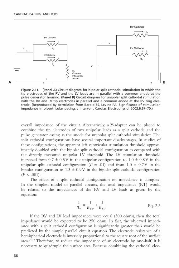
overall impedance of the circuit. Alternatively, a Y-adapter can be placed tocombine the tip electrodes of two unipolar leads as a split cathode and the pulse generator casing as the anode for unipolar split cathodal stimulation. Thesplit cathodal configurations have several important disadvantages. In studies ofthese configurations, the apparent left ventricular stimulation threshold approx-imately doubled with the bipolar split cathodal configuration as compared withthe directly measured unipolar LV threshold. The LV stimulation thresholdincreased from 0.7 ± 0.5V in the unipolar configuration to 1.0 ± 0.8V in theunipolar split cathodal configuration (P = .01) and from 1.0 ± 0.7V in thebipolar configuration to 1.3 ± 0.9V in the bipolar split cathodal configuration(P < .001).
The effect of a split cathodal configuration on impedance is complex.In the simplest model of parallel circuits, the total impedance (RT) would be related to the impedances of the RV and LV leads as given by the equation:
Eq. 2.3
If the RV and LV lead impedances were equal (500 ohms), then the totalimpedance would be expected to be 250 ohms. In fact, the observed imped-ance with a split cathodal configuration is significantly greater than would bepredicted by the simple parallel circuit equation. The electrode resistance of ahemispherical electrode is inversely proportional to the square root of the surfacearea.74,75 Therefore, to reduce the impedance of an electrode by one-half, it isnecessary to quadruple the surface area. Because combining the cathodal elec-
1 1 1R R RT RV LV
= +
CARDIAC PACING AND ICDS
66
RV Cathode
LV Cathode
R3
CommonIntracardiacAnode
R1
I1
I2
I
I
R2
RV Cathode
LV CathodeI2
I1
R1
R2
I
V
Figure 2.11. (Panel A) Circuit diagram for bipolar split cathodal stimulation in which thetip electrodes of the RV and the LV leads are in parallel with a common anode at thepulse generator housing. (Panel B) Circuit diagram for unipolar split cathodal stimulationwith the RV and LV tip electrodes in parallel and a common anode at the RV ring elec-trode. (Reproduced by permission from Barold SS, Levine PA. Significance of stimulationimpedance in biventricular pacing. J Intervent Cardiac Electrophysiol 2002;6:67–70.)
A B

trodes in this study results in an approximate doubling of the electrode surfacearea, the measured impedance is reduced by a factor of approximately (Fig.2.12). Thus, in practice, the total impedance with the split cathodal configura-tion of two leads each having an impedance of 500 ohms would be approxi-mated by:
Eq. 2.4
Thus, the impedance of two 500 ohms leads in a split cathodal configura-tion would be approximately 350 ohms.This equation gives a value that is muchcloser to what is observed clinically with a split cathode configuration.
The pacing pulse delivered by the pacing system analyzer is a truncatedexponential waveform.The rate of the exponential decay (or droop) of the stim-ulus waveform is affected by the surface area–dependent values of electrodeimpedance. The change in the rate of exponential decay that is produced bycombining two electrodes as a common cathode can lead to a change in pacingthreshold. Because the droop of the waveform contains lower frequencies thanthe leading edge, it is not only affected by the electrode interface resistance butalso by the interface capacitance. Because the capacitance of an electrode is pro-portional its surface area, the capacitance of two electrodes will approximatelydouble by combining two cathodes. The augmentation of capacitance anddecrease in resistance can increase the droop of the stimulus pulse, thereby low-ering the voltage before the end of the pulse and increasing the pacing thresh-old. Another limitation of the split cathodal configuration is that assessment ofthe electrical integrity of either the LV or the RV lead may be difficult. A com-plete fracture of the LV lead conductor or the RV tip conductor would haveonly a small affect on impedance. A fracture of the RV ring conductor wouldcreate a dramatic rise in impedance only if the output circuit is programmedbipolar. In addition, a low impedance of one of the leads due to an insulationfailure may be difficult to detect because of the already low impedance of theparallel circuit.
More recent generations of US Food and Drug Administration–approvedCRT devices use separate output circuits for both the cardiac venous and theright ventricular leads that allow independent programming of stimulationamplitude, pulse duration, and polarity. The use of bipolar leads for both theRV and LV, each with its own output circuit will further simplify CRT, espe-cially sensing.
SENSINGSensing of the cardiac electrogram is essential to the proper function of per-manent pacemakers. In addition to responding to appropriate intrinsic atrial orventricular electrograms, permanent pacing systems must be able to discrimi-nate these signals from unwanted electrical interference: far-field cardiac events,
R
R R
T
LV RV
=
+( )22
2
BASIC CONCEPTS OF PACING
67

CARDIAC PACING AND ICDS
68
RW´(right)
cathode (shared)
anode
CW´(right)
RT´(right)
RW´(left)
CW´(left)
CW´(right)CW´(left)
RT´(left)
RW´(right)
cathode (shared)
anode
RT´(right)
RW´(left)
RT´(left)
RW´(right)
cathode (shared)
anode
RT´(right)
RW´(left)
RT´(left)
CW´(right)CW´(left)
RW´(right)
cathode (left) cathode (right)
anode anode
RT´(right)
RW´(left)
RT´(left)
A B
C D
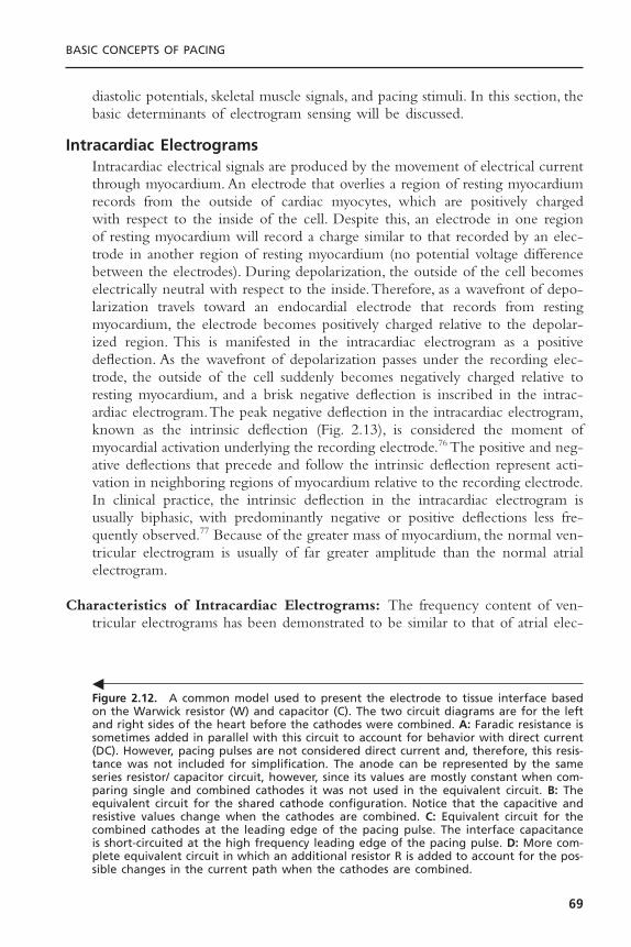
diastolic potentials, skeletal muscle signals, and pacing stimuli. In this section, thebasic determinants of electrogram sensing will be discussed.
Intracardiac ElectrogramsIntracardiac electrical signals are produced by the movement of electrical currentthrough myocardium. An electrode that overlies a region of resting myocardiumrecords from the outside of cardiac myocytes, which are positively charged with respect to the inside of the cell. Despite this, an electrode in one regionof resting myocardium will record a charge similar to that recorded by an elec-trode in another region of resting myocardium (no potential voltage differencebetween the electrodes). During depolarization, the outside of the cell becomeselectrically neutral with respect to the inside.Therefore, as a wavefront of depo-larization travels toward an endocardial electrode that records from restingmyocardium, the electrode becomes positively charged relative to the depolar-ized region. This is manifested in the intracardiac electrogram as a positivedeflection. As the wavefront of depolarization passes under the recording elec-trode, the outside of the cell suddenly becomes negatively charged relative toresting myocardium, and a brisk negative deflection is inscribed in the intrac-ardiac electrogram.The peak negative deflection in the intracardiac electrogram,known as the intrinsic deflection (Fig. 2.13), is considered the moment ofmyocardial activation underlying the recording electrode.76 The positive and neg-ative deflections that precede and follow the intrinsic deflection represent acti-vation in neighboring regions of myocardium relative to the recording electrode.In clinical practice, the intrinsic deflection in the intracardiac electrogram isusually biphasic, with predominantly negative or positive deflections less fre-quently observed.77 Because of the greater mass of myocardium, the normal ven-tricular electrogram is usually of far greater amplitude than the normal atrialelectrogram.
Characteristics of Intracardiac Electrograms: The frequency content of ven-tricular electrograms has been demonstrated to be similar to that of atrial elec-
BASIC CONCEPTS OF PACING
69
Figure 2.12. A common model used to present the electrode to tissue interface basedon the Warwick resistor (W) and capacitor (C). The two circuit diagrams are for the leftand right sides of the heart before the cathodes were combined. A: Faradic resistance issometimes added in parallel with this circuit to account for behavior with direct current(DC). However, pacing pulses are not considered direct current and, therefore, this resis-tance was not included for simplification. The anode can be represented by the sameseries resistor/ capacitor circuit, however, since its values are mostly constant when com-paring single and combined cathodes it was not used in the equivalent circuit. B: Theequivalent circuit for the shared cathode configuration. Notice that the capacitive andresistive values change when the cathodes are combined. C: Equivalent circuit for thecombined cathodes at the leading edge of the pacing pulse. The interface capacitanceis short-circuited at the high frequency leading edge of the pacing pulse. D: More com-plete equivalent circuit in which an additional resistor R is added to account for the pos-sible changes in the current path when the cathodes are combined.
�
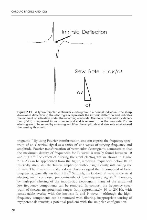
trograms.78 By using Fourier transformation, one can express the frequency spec-trum of an electrical signal as a series of sine waves of varying frequency andamplitude. Fourier transformation of ventricular electrograms demonstrates thatthe maximum density of frequencies for R waves is usually found between 10and 30Hz.78 The effects of filtering the atrial electrogram are shown in Figure2.14. As can be appreciated from the figure, removing frequencies below 10Hzmarkedly attenuates the T-wave amplitude without significantly influencing theR wave.The T wave is usually a slower, broader signal that is composed of lowerfrequencies, generally less than 5Hz.78 Similarly, the far-field R wave in the atrialelectrogram is composed predominantly of low-frequency signals.79 Therefore,by high-pass filtering of the intracardiac electrogram, many of the unwantedlow-frequency components can be removed. In contrast, the frequency spec-trum of skeletal myopotentials ranges from approximately 10 to 200Hz, withconsiderable overlap with the intrinsic R and P waves.78 Although the high-frequency components can be removed with filtering, inappropriate sensing ofmyopotentials remains a potential problem with the unipolar configuration.
CARDIAC PACING AND ICDS
70
Figure 2.13. A typical bipolar ventricular electrogram in a normal individual. The sharpdownward deflection in the electrogram represents the intrinsic deflection and indicatesthe moment of activation under the recording electrode. The slope of the intrinsic deflec-tion (dV/dt) is expressed in volts per second and is referred to as the slew rate. For anelectrogram to be sensed by a sensing amplifier, the amplitude and slew rate must exceedthe sensing threshold.
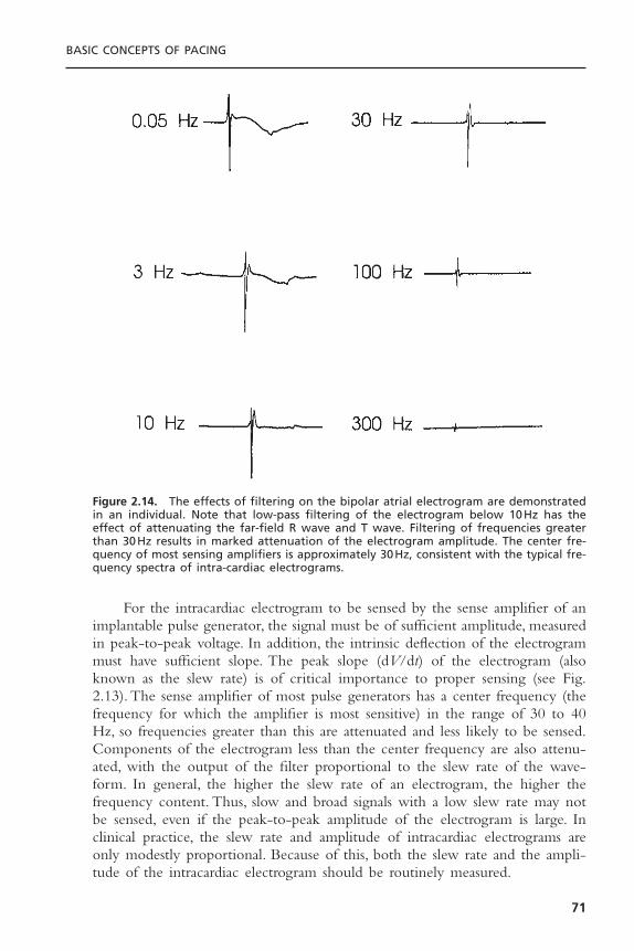
For the intracardiac electrogram to be sensed by the sense amplifier of animplantable pulse generator, the signal must be of sufficient amplitude, measuredin peak-to-peak voltage. In addition, the intrinsic deflection of the electrogrammust have sufficient slope. The peak slope (dV/dt) of the electrogram (alsoknown as the slew rate) is of critical importance to proper sensing (see Fig.2.13). The sense amplifier of most pulse generators has a center frequency (thefrequency for which the amplifier is most sensitive) in the range of 30 to 40Hz, so frequencies greater than this are attenuated and less likely to be sensed.Components of the electrogram less than the center frequency are also attenu-ated, with the output of the filter proportional to the slew rate of the wave-form. In general, the higher the slew rate of an electrogram, the higher thefrequency content. Thus, slow and broad signals with a low slew rate may notbe sensed, even if the peak-to-peak amplitude of the electrogram is large. Inclinical practice, the slew rate and amplitude of intracardiac electrograms areonly modestly proportional. Because of this, both the slew rate and the ampli-tude of the intracardiac electrogram should be routinely measured.
BASIC CONCEPTS OF PACING
71
Figure 2.14. The effects of filtering on the bipolar atrial electrogram are demonstratedin an individual. Note that low-pass filtering of the electrogram below 10Hz has theeffect of attenuating the far-field R wave and T wave. Filtering of frequencies greaterthan 30Hz results in marked attenuation of the electrogram amplitude. The center fre-quency of most sensing amplifiers is approximately 30Hz, consistent with the typical fre-quency spectra of intra-cardiac electrograms.
Unipolar and Bipolar Sensing
Although both unipolar and bipolar sensing configurations detect the differencein electrical potential between two electrodes, the interelectrode distance has aconsiderable influence on the nature of the electrogram.80 If a transvenousbipolar lead is used for sensing, both electrodes are located in the heart with aninterelectrode distance that is usually less than 3cm. A unipolar lead uses oneelectrode in contact with the heart and the other in contact with the pulse gen-erator, often with an interelectrode distance of 30 to 50cm. Because both elec-trodes may contribute to the electrical signal that is sensed, the bipolar electrodeconfiguration is minimally influenced by electrical signals that originate outsidethe heart. In contrast, the unipolar electrode configuration may detect electri-cal signals that originate near the pulse generator pocket as well as those frominside the heart. These features of unipolar sensing make this electrode config-uration much more susceptible to interference by electrical signals originatingin skeletal muscle (myopotentials). The myopotentials associated with pectoralmuscle contraction may be sensed by unipolar pacemakers, resulting in inap-propriate inhibition or triggering of pacing output. Bipolar sensing is relativelyimmune to myopotentials—a significant clinical advantage. Bipolar sensing is alsoless likely to be influenced by electromagnetic radiation from the environmentthan is unipolar sensing. Electrical interference from microwaves, electrocautery,metal detectors, diathermy, or radar is more commonly observed with unipolarthan with bipolar sensing.
A bipolar electrogram is actually the instantaneous difference in electricalvoltage between the two electrodes. Thus a bipolar electrogram can be con-structed by subtracting the absolute unipolar voltage recorded at the cathode(versus ground) from the unipolar voltage recorded at the anode (versus ground).Because the bipolar configuration represents the signal at the cathode minus thesignal at the anode, the net electrogram may be considerably different from thatof either unipolar electrogram alone. For example, if an advancing wavefront ofdepolarization is perpendicular to the interelectrode axis of a bipolar lead, eachelectrode will be activated at exactly the same time. Because the unipolar elec-trogram at each electrode will be similar and inscribed at the same time, theinstantaneous difference in voltage will be minimal. In this situation, the bipolarelectrogram will be markedly attenuated. A wavefront of depolarization travel-ing parallel to the interelectrode axis of a bipolar lead will activate one elec-trode before the other.The resulting bipolar electrogram may have significantlygreater amplitude than either unipolar electrogram alone. From these examplesit should be recognized that bipolar sensing is more sensitive to the directionin which the depolarizing wavefront travels than is unipolar sensing. Bipolarelectrograms are more likely to be influenced by phasic changes in orientationof the lead with respiration than are unipolar electrograms. Because of theseconsiderations, the electrogram measured at the time of lead implantation shouldbe recorded in the configuration that will be used for sensing by the pulse generator.
CARDIAC PACING AND ICDS
72
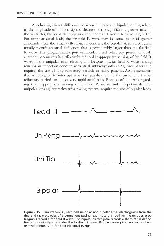
Another significant difference between unipolar and bipolar sensing relatesto the amplitude of far-field signals. Because of the significantly greater mass ofthe ventricles, the atrial electrogram often records a far-field R wave (Fig. 2.15).For unipolar atrial leads, the far-field R wave may be equal to or of greateramplitude than the atrial deflection. In contrast, the bipolar atrial electrogramusually records an atrial deflection that is considerably larger than the far-fieldR wave. The programmable post-ventricular atrial refractory period of dual-chamber pacemakers has effectively reduced inappropriate sensing of far-field Rwaves in the unipolar atrial electrogram. Despite this, far-field R wave sensingremains an important concern with atrial antitachycardia (AAI) pacemakers andrequires the use of long refractory periods in many patients. AAI pacemakersthat are designed to interrupt atrial tachycardias require the use of short atrialrefractory periods to detect very rapid atrial rates. Because of concerns regard-ing the inappropriate sensing of far-field R waves and myopotentials withunipolar sensing, antitachycardia pacing systems require the use of bipolar leads.
BASIC CONCEPTS OF PACING
73
Figure 2.15. Simultaneously recorded unipolar and bipolar atrial electrograms from thering and tip electrodes of a permanent pacing lead. Note that both of the unipolar elec-trograms record a far-field R wave. The bipolar electrogram records a sharp atrial deflec-tion and markedly attenuates the far-field R wave. Bipolar sensing is characterized by arelative immunity to far-field electrical events.

The problem of far-field R-wave detection in the atrial electrogram hasbeen addressed by Goldreyer and colleagues by the development of leads incor-porating a pair of closely spaced electrodes placed circumferentially around thecatheter.81,82 This concept, known as an orthogonal electrode array, uses elec-trodes that are separated by 180 degrees around the circumference of the leadbody.These electrodes do not contact the atrial myocardium directly but “float”free within the atrial blood pool. The advantage of orthogonal sensing is thatboth electrodes record ventricular activation nearly simultaneously, with amarked attenuation of the far-field R wave and a greater signal-to-noise ratio.The improved signal-to-noise characteristics of orthogonal electrodes haveallowed the use of more sensitive atrial amplifiers and increased reliability ofatrial sensing. Orthogonal electrodes have also provided a method for dual-chamber (VDD) pacing that uses a single lead. The single-lead concept uses anelectrode at the tip of the catheter, which is placed at the right ventricular apexfor ventricular pacing and sensing, and a pair of orthogonally arranged elec-trodes located more proximally along the catheter in the atrium for atrialsensing.
Sensing in Cardiac Resynchronization Tube DevicesThe first generation of CRT devices sensed the electrogram created by com-bining the left and right ventricular tip electrodes as a single electrode versusthe right ventricular ring electrode. The resulting composite electrogramincludes both right and left ventricular components (Fig. 2.16). If the width of
CARDIAC PACING AND ICDS
74
Figure 2.16. An example of loss of atrial tracking by a premature ventricular complex(PVC) that inhibits ventricular pacing for one beat, followed by double counting of theintrinsically conducted ventricular electrogram which represents a composite of RV andLV components. Because of the long intraventricular conduction delay (RV to LV), doublecounting of the ventricular electrogram resets the ventricular refractory period and thepost ventricular atrial refractory period (PVARP) such that the next atrial electrogramoccurs during PVARP. As a result, there is perpetuation of intrinsic conduction and failureto maintain consistent cardiac resynchronization therapy.

the combined electrogram exceeds the ventricular blanking period, the poten-tial exists for double counting of the ventricular rate. For pacemakers and ICDs,the most common manifestation is that of increasing the total atrial refractoryperiod (TARP). This is illustrated in Figure 2.17. Remember that the normalpost ventricular atrial refractory period begins after a sensed or paced ventric-ular event. When there is biventricular pacing, both ventricles are paced simul-taneously and the post ventricular atrial refractory period begins with theventricular pacing stimulus. However, when the ventricles are not paced, thesensed biventricular electrogram has two components (right followed by leftventricular components in the case of left bundle branch block). In this situa-tion, the post-ventricular atrial refractory period begins after the second com-ponent of the ventricular electrogram. When an atrial event is followed by abiventricular paced event, the total atrial refractory period is equal to the AVdelay + PVARP. On the other hand, when an atrial event is followed by a ven-tricular sensed event, the total atrial refractory period is equal to the AV delay+ the RV-LV delay + PVARP. This is illustrated in Figure 2.18, and by the fol-lowing equations:
Eq. 2.5
Eq. 2.6
in which pTARP is the paced total atrial refractory period, iTARP is the intrin-sic total atrial refractory period, AVD is the programmed AV delay, and IVCDis the interventricular conduction delay between right and left components ofthe biventricular sensed electrogram.The consequence of a greater iTARP thanpTARP is that ventricular tracking is maintained at faster rates when there is
iTARP AVD IVCD PVARP= + +( )atrial event followed by ventricular sensed event
pTARP AVD PVARP= +( )atrial event followed by biventricular pacing
BASIC CONCEPTS OF PACING
75
PVC
PVARP
VP
AS AS AS AR ARAR
VP VP VS VR VS VR VS VR VS VR
PVARP PVARP PVARP PVARP PVARP PVARP
Figure 2.17. Inhibition of atrial tracking by a PVC that extends the PVARP to 400 milli-seconds. As a result of post-PVC PVARP extension, the subsequent atrial electrogram fallswithin PVARP, inhibiting tracking and leading to persistent double counting of the ven-tricular electrograms during LBBB intrinsic conduction. (Courtesy of Medtronic, Inc.)
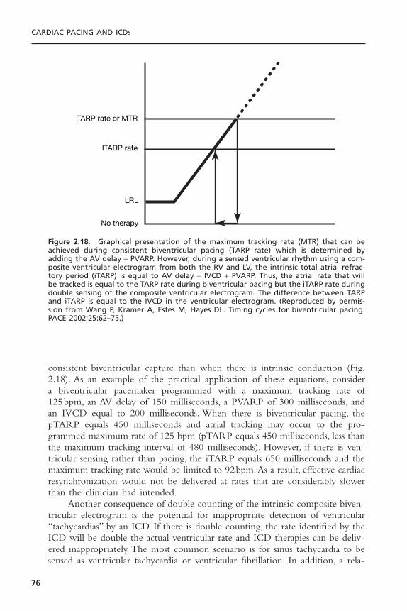
consistent biventricular capture than when there is intrinsic conduction (Fig.2.18). As an example of the practical application of these equations, consider a biventricular pacemaker programmed with a maximum tracking rate of 125bpm, an AV delay of 150 milliseconds, a PVARP of 300 milliseconds, andan IVCD equal to 200 milliseconds. When there is biventricular pacing, thepTARP equals 450 milliseconds and atrial tracking may occur to the pro-grammed maximum rate of 125 bpm (pTARP equals 450 milliseconds, less thanthe maximum tracking interval of 480 milliseconds). However, if there is ven-tricular sensing rather than pacing, the iTARP equals 650 milliseconds and themaximum tracking rate would be limited to 92bpm.As a result, effective cardiacresynchronization would not be delivered at rates that are considerably slowerthan the clinician had intended.
Another consequence of double counting of the intrinsic composite biven-tricular electrogram is the potential for inappropriate detection of ventricular“tachycardias” by an ICD. If there is double counting, the rate identified by theICD will be double the actual ventricular rate and ICD therapies can be deliv-ered inappropriately. The most common scenario is for sinus tachycardia to besensed as ventricular tachycardia or ventricular fibrillation. In addition, a rela-
CARDIAC PACING AND ICDS
76
TARP rate or MTR
ITARP rate
LRL
No therapy
Figure 2.18. Graphical presentation of the maximum tracking rate (MTR) that can beachieved during consistent biventricular pacing (TARP rate) which is determined byadding the AV delay + PVARP. However, during a sensed ventricular rhythm using a com-posite ventricular electrogram from both the RV and LV, the intrinsic total atrial refrac-tory period (iTARP) is equal to AV delay + IVCD + PVARP. Thus, the atrial rate that willbe tracked is equal to the TARP rate during biventricular pacing but the iTARP rate duringdouble sensing of the composite ventricular electrogram. The difference between TARPand iTARP is equal to the IVCD in the ventricular electrogram. (Reproduced by permis-sion from Wang P, Kramer A, Estes M, Hayes DL. Timing cycles for biventricular pacing.PACE 2002;25:62–75.)

tively slow ventricular tachycardia may be sensed at a rate double that the actualrate so that it falls in the ventricular fibrillation detection zone.
To overcome these limitations of biventricular sensing using a compositeventricular electrogram, the newer generations of ICDs stimulate both the rightand left ventricles but only use the right ventricular electrogram to determineventricular timing. This eliminates the potential for ventricular oversensing andmarkedly simplifies follow-up of these devices. Nevertheless, if both ventriclesare paced but only the right ventricle is sensed, there exists the possibility forleft ventricular premature depolarizations to be undersensed. In the worst casescenario, when there is a wide interval between RV and LV pacing, a VPD inthe LV could be undersensed and followed by an RV stimulus and then an LVstimulus that falls in the vulnerable period of the LV. To minimize this risk ICDmanufacturers have introduced such features as an LV protection period (LVPP)and an interventricular refractory period (IVRP) that allow sensing in the LVto inhibit ventricular pacing after a VPD without altering the basic timing cycleof the device.
PolarizationFollowing application of a polarizing pulse, an afterpotential of opposite chargeis induced in the myocardium at the interface of the stimulating electrode (Fig.2.19). Immediately after cathodal stimulation, an excess of positive charges sur-rounds the electrode, which then exponentially decays to electrical neutrality.This positively charged afterpotential can be inappropriately sensed by thesensing circuit of the pulse generator with resulting inhibition of the next pacingpulse.83 The amplitude of afterdepolarizations is directly related to the ampli-tude and duration of the pacing stimulus. Thus afterdepolarizations are mostlikely to be sensed during conditions of maximum stimulus voltage and pulseduration, combined with the maximum sensitivity setting of the pulse genera-
BASIC CONCEPTS OF PACING
77
Figure 2.19. Diagram of a constant-voltage output pulse (downward deflection) and aresultant afterpotential of opposite polarity. LE = leading edge, TE = trailing edge.
tor.84 The inappropriate sensing of near-field afterpotentials has been eliminatedby the use of sensing refractory periods that prevent the sensing circuit fromresponding to electrical signals for a programmable period following the pacingstimulus. However, for dual-chamber pacing systems, afterdepolarizations of sufficient amplitude in one chamber may be sensed by the sensing amplifier inthe other chamber. This is most likely to occur with the sensing of atrial after-potentials in the AV interval by the ventricular sensing circuit, resulting in inappropriate inhibition of ventricular stimulus output (crosstalk). Because of thepotential for inhibition of ventricular pacing by the far-field sensing of atrialafterdepolarizations, the ventricular sensing circuit is inactivated for a period(blanking period) following the delivery of an atrial pacing stimulus. Crosstalkis a rare clinical problem with bipolar pacing and sensing, however.
Time-Related Changes in Intracardiac ElectrogramsImmediately following implantation of a transvenous lead, the electrogram “STsegment” usually demonstrates a typical injury current. The current of injury iscaused by the pressure that is exerted by the distal electrode on myocardial cellmembranes. The current of injury is observed with both atrial and ventricularleads and is so typical of the acute electrogram that its absence may reflect mal-position of the lead with poor contact of the distal electrode and the endo-cardium. Lack of an injury current may also reflect placement of the lead in anarea of fibrotic myocardium. The injury current is observed with both activeand passive fixation electrodes. The injury current usually returns to the iso-electric line over a period ranging from several minutes to several hours.
The amplitude of the intracardiac electrogram typically declines abruptlywithin several days following implantation, with a gradual increase toward theacute value by 6 to 8 weeks.The chronic R-wave amplitude of passive fixationelectrodes has been shown to be approximately 85% of the acute value.32 Theattenuation of the slew rate is considerably greater, with chronic values averag-ing approximately 50% to 60% of the acute measurement. Corticosteroid-elutingleads have demonstrated minimal deterioration of the electrogram from implan-tation through regular follow-up assessments.42–46
Active fixation leads may be associated with a somewhat different timecourse than passive fixation leads in the evolution of the intracardiac electro-gram, with a markedly attenuated amplitude and slew rate immediately follow-ing lead positioning.33 Over the next 20 to 30 minutes, the electrogram amplitudetypically increases. It is likely that the trauma caused by extension of a screwhelix into the myocardium is responsible for this hyperacute evolution of theintracardiac electrogram. Recognition of this phenomenon may prevent theunnecessary repositioning of an active fixation lead. In general, active and passivefixation leads are associated with similar chronic electrogram amplitudes.32–85
Sensing ImpedanceThe intracardiac electrogram must be carried by the pacing lead from its sourcein the myocardium to the sensing amplifier of the pulse generator. The voltage
CARDIAC PACING AND ICDS
78

drop that occurs from the origin of the electrical signal in the heart to the prox-imal portion of the lead depends on the source impedance.The components ofsource impedance include the resistance between the electrode and themyocardium, the resistance offered by the lead conductor, and the effect ofpolarization. The electrode resistance is inversely related to the surface area ofthe electrode.68 Polarization impedance is also inversely related to electrodesurface area.Thus electrodes with large surface area minimize source impedanceand contribute to improved sensing.
The electrogram that is sensed by the pulse generator can also be attenu-ated by a mismatch in impedance between the lead (the source impedance) andthe sensing amplifier (input impedance).86,87 The greater the ratio of inputimpedance to source impedance, the less the electrogram is attenuated and themore accurately it reflects the true amplitude and morphology of the signal inthe myocardium.Thus the drop in electrogram amplitude from the actual voltagein the myocardium to the signal that is sensed by the pulse generator is mini-mized by a low-source impedance and a high-input impedance. The sourceimpedance of current pacing leads ranges from approximately 400 to 1500 ohms.The sensing amplifiers of currently available pulse generators typically have aninput impedance greater than 25,000 ohms. The clinical significance of imped-ance mismatch (too low a ratio of input impedance to source impedance) is thefailure of sensing with insulation failure or conductor fracture. An insulationfailure between the conductors of a bipolar lead results in shunting across theamplifier and an effective fall in input impedance. In this situation the electro-gram amplitude may be attenuated, with loss of appropriate sensing. A conduc-tor fracture leads to a marked increase in source impedance and a similarimpedance mismatch and sensing failure.
Automated Capture FeaturesTo ensure ventricular capture and to allow programming of a low margin ofsafety, several manufacturers of pacemakers have introduced algorithms that automatically detect ventricular capture and adjust the output of the pacingstimulus. The AutocaptureTM feature of St Jude Medical pacemakers allows thepacemaker to automatically adjust the amplitude of the stimulation pulse bydetecting capture in the ventricle (Fig. 2.20).These pacemakers require a bipolarventricular pacing lead that must have low polarization properties for the distalelectrode. The presence or absence of ventricular capture is determined bysensing of the evoked response (ER) from the ring electrode. These devicesautomatically determine the evoked response gain and sensitivity levels by deliv-ering five paired ventricular pulses at 4.5 V and a minimum pulse duration of0.5 milliseconds or the programmed value. The first of the paired pulses mea-sures the ER while the second pulse is delivered within 100 milliseconds of thefirst (in the physiologic refractory period of the myocardium) to determine thelevel of polarization. If the ER amplitude is greater than 2.5mV, the measuredlead polarization is less than 4.0mV, and the ratio of the ER to the ER sen-sitivity is greater than 1.8 :1, the device automatically determines that the safety
BASIC CONCEPTS OF PACING
79

80
Figure 2.20. Algorithms for automated determination of pacing and sensing thresholds.Top: (A) The St. Jude Medical AutoCapture algorithm documents ventricular capture ona beat-to-beat basis by detecting the local evoked electrical response that follows thepacing stimulus. After a 15-millisecond blanking period following the pacing stimulus,the evoked response detection window is open for the next 47.5 milliseconds. If the localevoked electrogram is detected, capture has occurred. B: If no evoked response isdetected, a high output backup pulse is delivered at the end of the sensing window toprovide capture. Two consecutive pulses without capture cause the device to redeterminethe capture threshold and adjust the output of the first stimulus to 0.25V above thresh-old. (Reproduced by permission from Clarke M, Liu B, Schuller H, et al. Automatic adjust-ment of pacemaker stimulation output correlated with continuously monitored capturethresholds: a multicenter study. European Microny Study Group. Pacing Clin Electrophys-iol 1998;21:1567–1575.) C: Intermedics automated algorithm to maintain a twofold safetymargin for sensing. Inner (solid line) and outer (dotted line) sensing target levels aremonitored. Sensing between the inner and outer target levels drives the sensitivity tomore sensitive settings. When the outer target is reached, the sensitivity is moved to lesssensitive settings. (Reproduced by permission from Castro A, Liebold A, Vincente J, et al.Evaluation of autosensing as an automatic means of maintaining a 2 :1 sensing safetymargin in an implanted pacemaker. Autosensing Investigation Team. Pacing Clin Elec-trophysiol 1996;19:1708–1713.)
C
margins are acceptable and AutoCapture is recommended. The AutoCapturefeature uses unipolar pacing from the tip electrode and determines capture ona beat-to-beat basis. If a ventricular stimulus is not followed by a detectableevoked response, a second test pulse is given at a value equal to 0.25 V abovethe last threshold measurement (a value known as the automatic pulse ampli-tude or APA). If a pulse is not followed by detectable capture, a backup pulseis delivered within 80 to 100 milliseconds at an amplitude of 4.5mV. If twoconsecutive APA pulses are not followed by an evoked response, the thresholdis measured to determine whether the APA needs adjustment. Specifically, thepulse is incremented 0.25 V above the last APA. If capture is not confirmed,the APA is repeated in 0.125-V increments until two consecutive captured events occur. The important point is that all loss of capture pulses are immedi-ately followed by a backup pulse. A potential complicating factor with detec-tion of the evoked response is differentiating fusion from capture. In theDDD(R) pacing mode, precisely timed intrinsic conduction can result in falsedetection of loss of capture.To differentiate true loss of capture from fusion, theAV delay is incremented by 100 milliseconds after two consecutive loss-of-capture events to search for intrinsic conduction. If intrinsic conduction isindeed present during this extension of the AV delay, the backup pulse is eliminated. On the other hand, if subsequent backup pulses or APA incrementsare required due to loss of capture, the AV/PV delay is shortened to 50/25 milliseconds. This sequence can introduce confusion into the interpretation ofelectrocardiographic tracings with irregular AV delays. However, knowledge ofthe function of the AutoCapture algorithm allows recognition that this is anormal phenomenon.
Other manufacturers offer variants of the automatic capture algorithm thatdo not deliver backup pulses on a beat-to-beat basis but provide automaticdetermination of pacing threshold at programmed intervals during the day.These devices determine the pacing threshold and adjust the pacing amplitudeto provide a programmed margin of safety. In general, automatic capture algo-rithms function quite effectively and may reduce the risk of loss of capture dueto fluctuations in pacing threshold due to drugs, metabolic derangement, or leaddislodgement. The capability for reducing the programmed margin of safety iseffective for prolonging battery life and may reduce the frequency of clinicfollow-ups. The Medtronic Ventricular Capture ManagementTM feature deter-mines a strength duration threshold at a programmable interval (nominal is onceper day).The amplitude threshold is determined at a pulse duration of 0.4 milli-seconds. Following this, the pulse amplitude is doubled and a pulse durationthreshold is measured.The permanent ventricular stimulation amplitude is thenautomatically reprogrammed using a programmable amplitude safety margin(usually twice threshold) or a programmable minimum amplitude (whichever ishigher). The nominal values for ventricular capture management are a safetymargin of twice threshold with a pulse duration of 0.4 milliseconds and aminimum ventricular amplitude of 2.5 V. During measurement of pacing thresh-old, each test pulse is followed by a backup pulse 110 milliseconds later to ensure
BASIC CONCEPTS OF PACING
81
that a pacing pause does not occur. If the automatically measured ventricularstimulation threshold is greater than 2.5 V at 0.4 milliseconds, the ventricularoutput is automatically programmed to 5.0 V and 1.0 millisecond.
The Medtronic Atrial Capture ManagementTM feature is designed to peri-odically measure the atrial stimulation threshold and adapt the atrial output toa programmable amplitude safety margin. This feature does not use the evokedpotential to determine the presence or absence of atrial capture. Rather, thepacemaker searches for evidence that atrial test pulses reset the sinus node (AtrialChamber Reset Method) or by observing the ventricular response to determineif a captured atrial test pulse is conducted to the ventricles through the AV con-duction system.The atrial capture management feature performs an atrial ampli-tude threshold at 0.4-millisecond pulse duration and after loss of capture isdetected (defined as two of three test pulses indicating loss of capture) the ampli-tude setting is increased until atrial capture is confirmed. Since this feature doesnot rely on detection of the evoked response, there is no restriction on the typeof atrial lead that can be used. This feature will not measure thresholds if thesinus rate is consistently faster than 87bpm.
Autosensing FunctionsBecause the most common cause of anomalous pacemaker behavior relates toproblems with sensing, several manufacturers have introduced pacemakers thatautomatically determine the amplitude of P- and R-waves and reprogram theatrial and ventricular sensitivity settings to maintain an acceptable sensing safetymargin (see Fig. 2.20).The clinical utility of autosensitivity is highlighted by theobservation that programming a 100% sensing safety margin based on a singleP-wave measurement provides reliable atrial sensing in only 72% of patients withdual-chamber pacemakers. The Medtronic Sensing Assurance feature measuresthe amplitude of P- and R-waves and classifies each as low, high, or adequatebased on a non-programmable target-sensing margin. This feature attempts toreprogram the atrial sensitivity value so that the atrial electrogram is maintainedwithin a range that is 4.0 to 5.6 times the programmed sensitivity value. Forexample, if the atrial sensitivity value is programmed to 0.5mV, an atrial elec-trogram amplitude between 0.5 and 2.0mV the sensing margin is classified aslow (between 1.0 and 4.0 times sensitivity value); if between 2.0 and 2.8 it isclassified as adequate (between 4.0 and 5.6 times sensitivity value); and if greaterthan 2.8mV, it is classified as high (>5.6 times). In the ventricle, the safety marginis maintained between 2.8 and 4.0 times.
LEAD DESIGNPermanent pacing leads have five major components: 1) the electrode(s); 2) theconductor(s); 3) insulation; 4) the connector pin; and 5) the fixation mecha-nism. Each of these components has critical design considerations, as well asfailure modes. In this section, the factors that are important for design of leadsare reviewed.
CARDIAC PACING AND ICDS
82

ElectrodesAs discussed previously in this chapter, the stimulation threshold is a functionof the current density generated at the electrode.26,34–36 In general, the smallerthe radius of the electrode, the greater the current density. The resistance at theelectrode-myocardial interface is higher with smaller electrodes, providing forthe efficient use of a constant-voltage pulse and improving battery longevity.Both of these factors favor electrodes with small radius for myocardial stimula-tion. In contrast, sensing impedance and electrode polarization are decreasedwith electrodes of larger surface area.26,68,83,84 Although higher sensing imped-ance with a small electrode is easily compensated by a higher input impedanceof the sensing amplifier, the issue of polarization favors the use of a large elec-trode to minimize afterpotentials.The ideal pacing lead would have an electrodewith a small radius (to increase current density) and a large surface area (toreduce polarization).68 The solution to these conflicting considerations foroptimal stimulation and sensing characteristics has been addressed by the devel-opment of electrodes that have a small radius but a complex surface structurethat provides a large surface area.66–70,83
Electrode Shape: The effect of electrode shape on current density has been studiedextensively by Irnich and colleagues. Electrodes with a smooth, hemisphericalshape produce a uniform current density. In contrast, electrodes with morecomplex shapes typically produce an irregular pattern of current density,with “hot spots” at the edges and points of the electrode. Electrodes with anirregular shape enable a high current density to be maintained at these hot spotswhile presenting a larger overall surface area to the endocardial surface. Forexample, a ring-tipped electrode resulted in better stimulation thresholds andsensing characteristics than did the older hemispherical electrode designs. Otherelectrode shapes that were introduced to produce areas of high current densityincluded a grooved hemispherical design and a dish-shaped design with holesbored into the electrode. Leads with helical, screw-shaped electrodes, hooks, andbarbs have all been demonstrated to provide areas of increased current densityand acceptable stimulation thresholds. Most modern leads have used a small electrode with a complex surface structure to achieve improved stimulation andsensing characteristics.
Surface Structure: Early pacing leads used electrodes with a polished metal surface.The use of electrodes with a textured surface has resulted in a dramatic increasein the surface area of the electrode without an increase in radius.68–70 The tex-tured surface of modern leads minimizes polarization and improves sensing andstimulation efficiency.The surface of an electrode may be porous, with a struc-ture containing thousands of microscopic pores ranging from 20 to 100mm.Thesurface of some leads is coated with sintered microspheres of Elgiloy, platinum,or iridium oxide. In addition, the electrode may be constructed of a woven
BASIC CONCEPTS OF PACING
83
mesh of microscopic metallic fibers enclosed within a screened basket of wire.The performance of carbon electrodes has been improved by roughening of thesurface, a process that is known as activation. Each of these porous or roughenedsurface structures has been shown to minimize polarization greatly; such a struc-ture can lead to the ingrowth of tissue into the electrode.
The ability to differentiate an evoked intracardiac electrogram from after-potentials is greatly influenced by the polarization characteristics of the elec-trode. The importance of electrodes with low polarization has greatly increasedas pacing systems with the capability to automatically measure the pacing thresh-old through accurate capture detection have been introduced. In fact, automaticdetection of capture may not be possible with some leads having high ampli-tude afterpotentials. Although sensing is improved by the porous electrodedesign, the improvement in chronic stimulation thresholds has been mainlyaccomplished by the use of corticosteroid elution and atraumatic fixation mechanisms.
Chemical Composition: To minimize inflammation and subsequent fibrosis at thetissue interface, electrodes for permanent pacing leads should be biologicallyinert and resistant to chemical degradation. Certain metals, such as zinc, copper,mercury, nickel, lead, and silver, are associated with toxic reactions in themyocardium and are unsuitable for use in the electrodes of chronically implantedleads.88 In addition to these materials with direct tissue toxicity, metals that aresusceptible to corrosion have been demonstrated to result in increased chronicstimulation thresholds. Stainless steel alloys are variably associated with thepotential for corrosion. Titanium and tantalum have been shown to acquire asurface coating of oxides, which may impede charge transfer at the electrodeinterface. However, titanium that is coated with microscopic particles of plat-inum or vitreous carbon has been found to have excellent long-term perfor-mance as a pacing electrode.69,70 The polarity of the electrode may also have animportant influence on its chemical stability. For example, Elgiloy is a quiteacceptable electrode material when used as the cathode. However, when usedas the anode, Elgiloy is susceptible to a significant degree of corrosion.
The materials presently in use for the electrodes of permanent pacing leadsinclude platinum-iridium, Elgiloy, platinum coated with platinized titanium,vitreous or pyrolytic carbon coating a titanium or graphite core, platinum, oriridium oxide. The platinized-platinum and iridium-oxide electrodes have beenassociated with a reduced degree of polarization. Although a small degree ofcorrosion may occur with any of these materials, the carbon electrodes appearto be less susceptible. The carbon electrodes have been improved by roughen-ing the surface, a process known as activation, which reduces polarization. Thechronic thresholds of the activated carbon electrodes compare favorably to thoseobserved with platinum–iridium and Elgiloy.69
Steroid-Eluting Electrodes: A major advance in permanent pacing lead technol-ogy has been the development of electrodes that elute small amounts of the
CARDIAC PACING AND ICDS
84

corticosteroid dexamethasone sodium phosphate.42–45 The steroid-eluting elec-trodes incorporate a silicone core that is impregnated with a small quantity ofdexamethasone (Fig. 2.21). The core is surrounded by a porous titanium elec-trode that is coated with platinum. The steroid-eluting leads are characterizedby a minimal change in stimulation threshold from implantation to a follow-upperiod of several years.The acute peak in stimulation threshold is virtually elim-inated with these leads.The variation in chronic threshold among individuals issignificantly reduced, allowing the confident use of lower pacing amplitudes. Itshould be emphasized that the corticosteroid eluted from the lead does not affectacute stimulation thresholds. Rather, dexamethasone controls the chronic evo-lution of the pacing threshold.The design characteristics associated with reducedpolarization and chemical stability remain important considerations, even withsteroid-eluting leads. Steroid elution may also be accomplished with a drug-impregnated collar that surrounds the tip electrode. Corticosteroid leads are nowroutinely used for both active and passive fixation designs and have dramaticallyreduced the risk of exit block (an excessive increase in chronic stimulationthreshold) for endocardial pacing and ICD leads as well as for epimyocardialleads.
The studies of Stokes and Bornzin have indicated that the mechanism bywhich dexamethasone sodium phosphate prevents a rise in chronic stimulation
BASIC CONCEPTS OF PACING
85
Figure 2.21. Diagram of a steroid-eluting electrode with a reservoir of dexamethasonesodium phosphate that slowly elutes through the electrode into the underlying myo-cardium. (Courtesy of Medtronic, Inc.)

threshold remains to be fully explained.46 Although the thickness of the fibrouscapsule that surrounds the electrode is reduced, the magnitude is less than wouldbe expected by the evolution in stimulation threshold. This suggests that othermechanisms may be involved. In addition to studies of the steroid-eluting elec-trodes, clinical studies of pacing leads incorporating a drug-eluting collar sur-rounding the electrode are ongoing.46 The duration that drug elution is requiredfor sustained low thresholds remains to be fully defined. Nevertheless, long-termfollow-up for over 10 years has indicated that the impressively low chronicthresholds observed with steroid-eluting electrodes appear to be maintained overthe usable entire service life of most pacing leads. The routine use of steroid-eluting leads with high electrode resistance has allowed pulse generators to bereduced in size, because of a reduced battery capacity, while maintaining accept-able longevity.
Fixation Mechanism: The chronic performance of permanent pacing leads is criti-cally dependent on stable positioning of the electrode(s). Although early pacingleads were associated with an unacceptably high risk of dislodgment, the devel-opment of active and passive fixation mechanisms has dramatically reduced theneed for lead repositioning.89 Previous generations of permanent transvenouspacing leads included several appendages at the distal end that were designed tolodge within the trabeculae of the right atrium or ventricle. However, tines havebecome the predominant fixation mechanism currently used for passive perma-nent pacing leads (Fig. 2.22).90 Passive fixation leads are typically entrappedwithin the trabeculae of the right heart chambers immediately upon correctpositioning of the lead. Effective fixation of the lead can be confirmed at thetime of implantation by gentle traction or rotation of the lead. Tines generallyadd minimal technical difficulty to the implantation procedure, although theymay occasionally become entrapped in the tricuspid valve apparatus.The passivefixation devices are rapidly covered by fibrous tissue, making later removal ofthe lead by simple traction difficult or impossible in as short a time as 6 months.Besides the effectiveness of passive fixation devices to prevent dislodgment, theincreased stability that is provided for the distal electrode serves to minimizetrauma at the myocardial interface caused by motion.This added stability is likelyto result in a smaller fibrous capsule surrounding the electrode and improve-ment of the chronic stimulation threshold.The passive fixation devices have therelative disadvantage of increasing the maximum external diameter of the lead,requiring the use of a larger venous introducer when the subclavian vein punc-ture technique is used. Removability of pacing leads is an important consider-ation. In general, passive fixation leads are more difficult to extract than activefixation leads.
Active Fixation Leads: Although several different fixation methods such as screws,barbs, or hooks have been developed, the present generation of active fixationpacing leads largely relies on a screw helix that is extended into the endocardium(see Fig. 2.22).91,92 The screw helix may be permanently exposed from the tip
CARDIAC PACING AND ICDS
86

of the lead (a fixed-screw), requiring the lead to be rotated in a counterclock-wise direction during passage through the vasculature. Other leads allow thescrew helix to be extended from the tip once the lead has been atraumaticallypassed through the venous system to the heart (an extendable-retractable screw;Fig. 2.23). The design of Bisping and colleagues incorporates an extendable-retractable helical screw that is well suited for positioning at several sites in theatrium or ventricle at the time of implantation.91 Active fixation leads may usethe screw helix as both the fixation mechanism and the electrically active elec-trode (see Fig. 2.23). Other designs use a separate electrode at the distal end ofthe lead for stimulation and sensing with an electrically inactive helix. Althoughboth devices provide similar long-term thresholds, the inactive helix leads areassociated with lower acute thresholds. Another approach to active fixation leadsuses a cap of mannitol or polyethylene glycol over the screw helix to facilitateintroduction of the lead into the vasculature. After approximately 5 minutes inthe blood pool, the mannitol or polyethylene glycol dissolves, allowing the screwto engage the endocardium.
BASIC CONCEPTS OF PACING
87
Figure 2.22. Common types of permanent transvenous pacing electrodes. A: Active fix-ation lead with extendable helix (helix retracted). B: Active fixation lead with helixextended. C: Fixed helix active fixation lead with helix covered by dissolvable mannitolcoating. D: Straight tined passive fixation lead. E: Pre-formed “J” passive fixation tinedlead for positioning in the right atrial appendage. This lead has a very small diametertipo electrode that provides a high pacing lead impedance at the electrode-tissue inter-face. F: Unipolar 4F pre-formed coronary sinus lead for left ventricular pacing. The curvedshape helps to hold the lead in position in the coronary veins. All leads except the coro-nary sinus lead are bipolar but note the differing distances between the ring and tipelectrodes.

The extendable-retractable design has become the most widely prescribedactive fixation mechanism because of its ease of implantation and because thefixation mechanism can be retracted long after implantation, thereby allowingfor an easier extraction procedure.
Active fixation leads offer the implanting physician the capability for stablepositioning of the lead at many sites in either the atrium or the ventricle.Although active fixation leads have significantly reduced the risk of atrial leaddislodgment, the chronic pacing thresholds are somewhat higher than those ofpassive fixation leads.This difference in long-term pacing threshold has becomeonly a minor issue with the routine use of corticosteroid elution in active fix-ation leads. Active fixation leads may also be used in the ventricle and may haveparticular usefulness in rheumatic heart disease associated with endocardial scar-ring. In patients with either congenital or surgically corrected transposition ofthe great vessels who require transvenous pacing, active fixation leads may beplaced in the anatomic left ventricle, which has minimal trabeculae. Althoughactive fixation leads are potentially easier to extract than passive fixation leads,the risk of myocardial perforation during implantation is higher. Because thestimulation thresholds of active fixation leads tend to be similar to those
CARDIAC PACING AND ICDS
88
Figure 2.23. A bipolar Bisping-type active fixation that uses the screw helix as the active,distal electrode. The screw helix is extended into the endocardium by rotating the prox-imal connector of the lead. The screw helix is both extendable and retractable, allowingatraumatic passage through the vasculature. (Courtesy of Medtronic, Inc.)
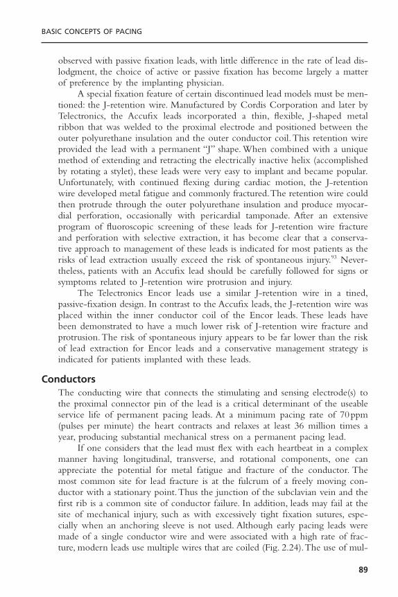
observed with passive fixation leads, with little difference in the rate of lead dis-lodgment, the choice of active or passive fixation has become largely a matterof preference by the implanting physician.
A special fixation feature of certain discontinued lead models must be men-tioned: the J-retention wire. Manufactured by Cordis Corporation and later byTelectronics, the Accufix leads incorporated a thin, flexible, J-shaped metalribbon that was welded to the proximal electrode and positioned between theouter polyurethane insulation and the outer conductor coil.This retention wireprovided the lead with a permanent “J” shape. When combined with a uniquemethod of extending and retracting the electrically inactive helix (accomplishedby rotating a stylet), these leads were very easy to implant and became popular.Unfortunately, with continued flexing during cardiac motion, the J-retentionwire developed metal fatigue and commonly fractured.The retention wire couldthen protrude through the outer polyurethane insulation and produce myocar-dial perforation, occasionally with pericardial tamponade. After an extensiveprogram of fluoroscopic screening of these leads for J-retention wire fractureand perforation with selective extraction, it has become clear that a conserva-tive approach to management of these leads is indicated for most patients as therisks of lead extraction usually exceed the risk of spontaneous injury.93 Never-theless, patients with an Accufix lead should be carefully followed for signs orsymptoms related to J-retention wire protrusion and injury.
The Telectronics Encor leads use a similar J-retention wire in a tined,passive-fixation design. In contrast to the Accufix leads, the J-retention wire wasplaced within the inner conductor coil of the Encor leads. These leads havebeen demonstrated to have a much lower risk of J-retention wire fracture andprotrusion.The risk of spontaneous injury appears to be far lower than the riskof lead extraction for Encor leads and a conservative management strategy isindicated for patients implanted with these leads.
ConductorsThe conducting wire that connects the stimulating and sensing electrode(s) tothe proximal connector pin of the lead is a critical determinant of the useableservice life of permanent pacing leads. At a minimum pacing rate of 70ppm(pulses per minute) the heart contracts and relaxes at least 36 million times ayear, producing substantial mechanical stress on a permanent pacing lead.
If one considers that the lead must flex with each heartbeat in a complexmanner having longitudinal, transverse, and rotational components, one canappreciate the potential for metal fatigue and fracture of the conductor. Themost common site for lead fracture is at the fulcrum of a freely moving con-ductor with a stationary point.Thus the junction of the subclavian vein and thefirst rib is a common site of conductor failure. In addition, leads may fail at thesite of mechanical injury, such as with excessively tight fixation sutures, espe-cially when an anchoring sleeve is not used. Although early pacing leads weremade of a single conductor wire and were associated with a high rate of frac-ture, modern leads use multiple wires that are coiled (Fig. 2.24).The use of mul-
BASIC CONCEPTS OF PACING
89
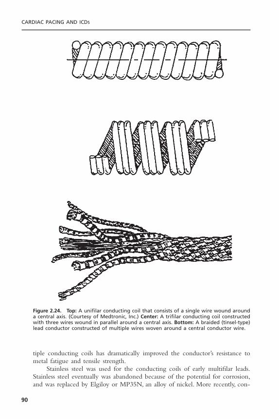
tiple conducting coils has dramatically improved the conductor’s resistance tometal fatigue and tensile strength.
Stainless steel was used for the conducting coils of early multifilar leads.Stainless steel eventually was abandoned because of the potential for corrosion,and was replaced by Elgiloy or MP35N, an alloy of nickel. More recently, con-
CARDIAC PACING AND ICDS
90
Figure 2.24. Top: A unifilar conducting coil that consists of a single wire wound arounda central axis. (Courtesy of Medtronic, Inc.) Center: A trifilar conducting coil constructedwith three wires wound in parallel around a central axis. Bottom: A braided (tinsel-type)lead conductor constructed of multiple wires woven around a central conductor wire.
ductors manufactured with the drawn-brazed-strand (DBS) technique have beenintroduced.The DBS conductor is made of six nickel alloy wires that are drawntogether with heated silver.The silver forms the matrix of the conductor, occu-pying the central core and the spaces between the nickel alloy wires. Silver alsoforms a thin outer layer that coats the conductor. DBS conductors are charac-terized by excellent resistance to flexion-related fracture.This conductor also hasa very low ohmic resistance, allowing more efficient delivery of the stimulatingpulse to the electrode and reduced sensing impedance. The Medtronic 6972polyurethane-insulated lead was found to be associated with insulation failuresthat were related to internal oxidation of the polyurethane by silver chloridefrom the DBS conductor. Because of the potential for oxidation of polyurethaneby silver complexes, DBS conductors are no longer used with polyurethane-insulated leads.
Bipolar leads are usually constructed of the coaxial design, with the con-ductor coil to the distal electrode within the outer conductor coil, which endsat the proximal electrode (Fig. 2.25). Older bipolar leads incorporate two con-ductor coils wound side by side within the insulating sleeve (see Fig. 2.25A).The coaxial design also requires that insulation be placed around both conduc-tors, making the overall external diameter rather large (see Fig. 2.25B). Coaxialbipolar leads are also less flexible than unipolar leads (see Fig. 2.25B). Thesecharacteristics have inhibited some physicians from using bipolar pacing leadsroutinely. A newer generation of bipolar pacing leads uses two conductors thatare coiled in parallel, allowing the external diameter of a bipolar lead to be nolarger than with a standard unipolar design (see Fig. 2.25A, bottom). These“Fine-Line” leads have been proven to provide excellent durability with a verythin lead body.
InsulationThe materials used for the insulation of permanent pacing leads are of two vari-eties, silicone rubber and polyurethane (Table 2.1). Silicone rubber has provento be a reliable insulating material in over four decades of clinical experience.Silicone is a relatively fragile material, however, with a low tear strength. Becausethe insulation of permanent pacing leads may be subjected to trauma during orafter implantation, the silicone layer must be thicker than it would be if it werestronger. Although the size of silicone-insulated unipolar leads has been clini-cally acceptable, coaxial bipolar leads constructed of this material have been ofrelatively large external diameter (often 10-F or greater). In addition, siliconerubber exposed to blood has a high coefficient of friction, making the manip-ulation of two leads in a single vein difficult. These disadvantages have beenaddressed by the introduction of platinum-cured silicone rubber, which is char-acterized by improved mechanical strength.The coefficient of friction has beengreatly reduced by the development of a lubricious, “fast-pass” coating. Theseimproved silicone leads are of smaller external diameter and are far easier tomanipulate when in contact with another lead.
BASIC CONCEPTS OF PACING
91

CARDIAC PACING AND ICDS
92
Figure 2.25. A (Top left): A bipolar lead with two conductor coils that are wound coaxially. The inner coil connects to the tip electrode, and the outer coil connects to thering electrode. A sleeve of insulation separates the coils. Top right: A bipolar lead con-ductor using two unifilar coils placed in parallel (side by side) with surrounding insulation.(Courtesy of Medtronic, Inc.) Bottom: A schematic representation of a multiconductorlead with two Teflon-insulated conducting wires wound in parallel and encased withina polyurethane insulating sleeve. This construction provides a smaller diameter to thelead body than does the standard coaxial design. (Courtesy of St. Jude Medical, Inc.) B (Top): A schematic of a standard bipolar coaxial lead with inner and outer conductorcoils and inner and outer insulation sleeves. Bottom: A schematic of a unipolar lead with a quadrafilar conducting coil surrounded by a sleeve of insulation. (Courtesy of St. Jude Medical, Inc.)
A
B

Polyurethane was introduced as an insulation material because of its supe-rior tear strength and low coefficient of friction. These properties allowpolyurethane leads to be constructed with smaller external diameter than thosemade with conventional silicone rubber. The smaller polyurethane leads havecontributed to the increased acceptance of bipolar pacing and have allowed twoleads to be placed in a single vein, also contributing to the ease of dual-chamberpacemaker implantation.
Two major forms of polyurethane, known as P80A and P55D, have beenused to insulate permanent pacing leads. The P80A polymer, which is less stiffthan the P55D variety, was used in the first polyurethane-insulated cardiacpacing leads. The P55D polymer, which has greater tensile and tear strength,has been used as the insulating material for the pacing leads of several manu-facturers. The P55D polymer is now the predominant form of polyurethaneused for pacing leads.
Within 4 years of the first human implant, polyurethane insulation failuresbecame clinically apparent. The model 6991U unipolar atrial lead with a pre-formed J shape demonstrated a pattern of insulation failure in the J-region ina minority of cases.94 The model 6972 bipolar ventricular lead was found tohave surface cracks in the P80A polyurethane insulation and clinical evidenceof insulation failure (Fig. 2.26). The initial polyurethane-insulated leads haveshown a high incidence of microscopic cracks in the outer surface of the insu-lation material. Extensive investigations by Stokes have shown that the surfacecracks are likely related to environmental stresses rather than to biologic degra-
BASIC CONCEPTS OF PACING
93
Table 2.1. Pacemaker Lead Insulation
Advantages Disadvantages
Silicone rubber • 30-year proven history • Tears easily (nicks, ligatures)• Repairable • Cuts easily• Low process sensitivity • Low abrasion resistance• Easy fabrication/molding • High friction in blood• Very flexible • Requires thicker walls (large
diameter)• More thrombogenic and fibrotic• Subject to cold flow failure• Absorbs lipids (calcification)
Polyurethane • 10-year proven history (55D) • Relatively stiff (especially 55D)• High tear strength • Not repairable• High cut resistance • Manufacturing process sensitive• Low friction in blood • Environmental stress cracking (ESC)• High abrasion resistance • Metal ion oxidation (MIO)• Thinner walls possible (small • History of clinical failures (80A)
diameter)• Relatively nonthrombogenic
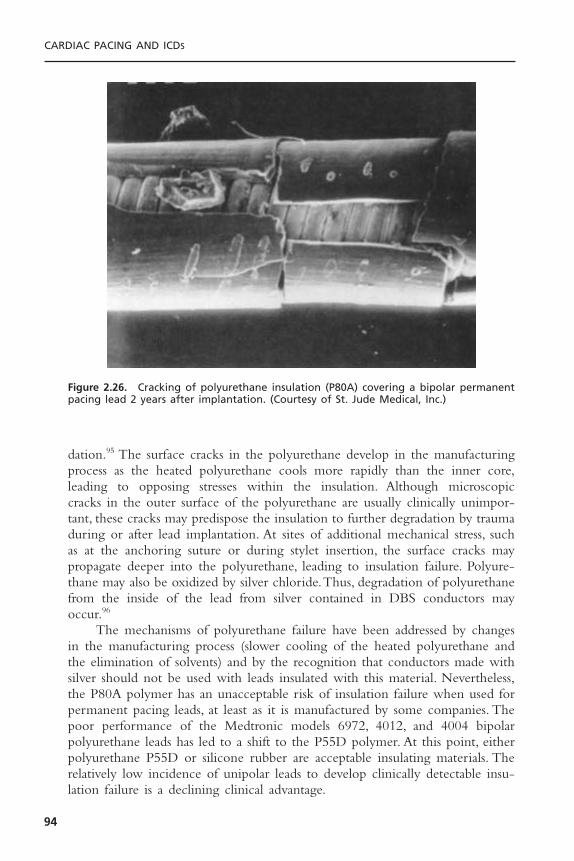
dation.95 The surface cracks in the polyurethane develop in the manufacturingprocess as the heated polyurethane cools more rapidly than the inner core,leading to opposing stresses within the insulation. Although microscopic cracks in the outer surface of the polyurethane are usually clinically unimpor-tant, these cracks may predispose the insulation to further degradation by traumaduring or after lead implantation. At sites of additional mechanical stress, suchas at the anchoring suture or during stylet insertion, the surface cracks maypropagate deeper into the polyurethane, leading to insulation failure. Polyure-thane may also be oxidized by silver chloride.Thus, degradation of polyurethanefrom the inside of the lead from silver contained in DBS conductors mayoccur.96
The mechanisms of polyurethane failure have been addressed by changesin the manufacturing process (slower cooling of the heated polyurethane andthe elimination of solvents) and by the recognition that conductors made withsilver should not be used with leads insulated with this material. Nevertheless,the P80A polymer has an unacceptable risk of insulation failure when used forpermanent pacing leads, at least as it is manufactured by some companies. Thepoor performance of the Medtronic models 6972, 4012, and 4004 bipolarpolyurethane leads has led to a shift to the P55D polymer. At this point, eitherpolyurethane P55D or silicone rubber are acceptable insulating materials. Therelatively low incidence of unipolar leads to develop clinically detectable insu-lation failure is a declining clinical advantage.
CARDIAC PACING AND ICDS
94
Figure 2.26. Cracking of polyurethane insulation (P80A) covering a bipolar permanentpacing lead 2 years after implantation. (Courtesy of St. Jude Medical, Inc.)

Epimyocardial LeadsPermanent pacing leads that are sutured to the epicardium or screwed into themyocardium of either the atrium or ventricle are presently used in clinical sit-uations involving abnormalities of the tricuspid valve, congenital heart disease,or when permanent pacing leads are implanted during intrathoracic surgical pro-cedures (Fig. 2.27). Epimyocardial electrodes use a fishhook shape that is stabbedinto the atrial myocardium, a screw helix that is rotated into the ventricle, orloops that are placed within epicardial stab wounds in the ventricle.The chronicstimulation thresholds with myocardial leads tend to be higher than withmodern endocardial electrodes, although there is considerable overlap. The useof three turns on an epicardial screw has been demonstrated to decrease the riskof exit block when compared to a two-turn screw. The incorporation of corti-costeroid-eluting electrodes into the design of myocardial leads has significantlyimproved the long-term performance of epicardial pacing, especially in childrenwith congenital heart disease, a group of patients with a very high risk of exitblock with older lead designs. Epicardial leads now incorporate bipolar elec-trodes with steroid elution that can be sutured onto the epicardial surfacewithout the requirement for a traumatic screw. These leads have greatly im-proved the outcome of epicardial pacing for selected patients. The introductionof CRT devices has provided for a resurgence in the clinical use of epicardialleads for left ventricular stimulation.
BASIC CONCEPTS OF PACING
95
Figure 2.27. Unipolar epicardial screw-in electrode with a screw helix that is rotated intothe myocardium. (Courtesy of St. Jude Medical, Inc.)
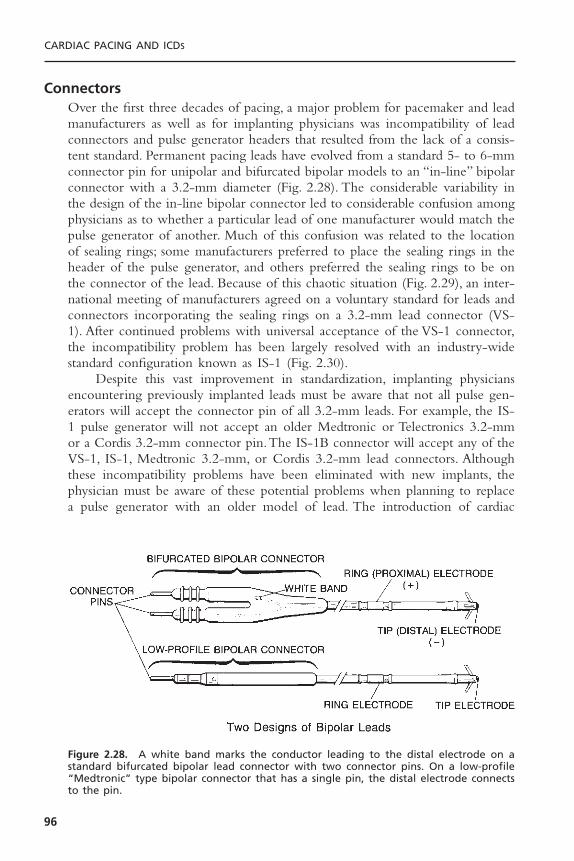
ConnectorsOver the first three decades of pacing, a major problem for pacemaker and leadmanufacturers as well as for implanting physicians was incompatibility of leadconnectors and pulse generator headers that resulted from the lack of a consis-tent standard. Permanent pacing leads have evolved from a standard 5- to 6-mmconnector pin for unipolar and bifurcated bipolar models to an “in-line” bipolarconnector with a 3.2-mm diameter (Fig. 2.28). The considerable variability inthe design of the in-line bipolar connector led to considerable confusion amongphysicians as to whether a particular lead of one manufacturer would match thepulse generator of another. Much of this confusion was related to the locationof sealing rings; some manufacturers preferred to place the sealing rings in theheader of the pulse generator, and others preferred the sealing rings to be onthe connector of the lead. Because of this chaotic situation (Fig. 2.29), an inter-national meeting of manufacturers agreed on a voluntary standard for leads andconnectors incorporating the sealing rings on a 3.2-mm lead connector (VS-1). After continued problems with universal acceptance of the VS-1 connector,the incompatibility problem has been largely resolved with an industry-widestandard configuration known as IS-1 (Fig. 2.30).
Despite this vast improvement in standardization, implanting physiciansencountering previously implanted leads must be aware that not all pulse gen-erators will accept the connector pin of all 3.2-mm leads. For example, the IS-1 pulse generator will not accept an older Medtronic or Telectronics 3.2-mmor a Cordis 3.2-mm connector pin.The IS-1B connector will accept any of theVS-1, IS-1, Medtronic 3.2-mm, or Cordis 3.2-mm lead connectors. Althoughthese incompatibility problems have been eliminated with new implants, thephysician must be aware of these potential problems when planning to replacea pulse generator with an older model of lead. The introduction of cardiac
CARDIAC PACING AND ICDS
96
Figure 2.28. A white band marks the conductor leading to the distal electrode on astandard bifurcated bipolar lead connector with two connector pins. On a low-profile“Medtronic” type bipolar connector that has a single pin, the distal electrode connectsto the pin.
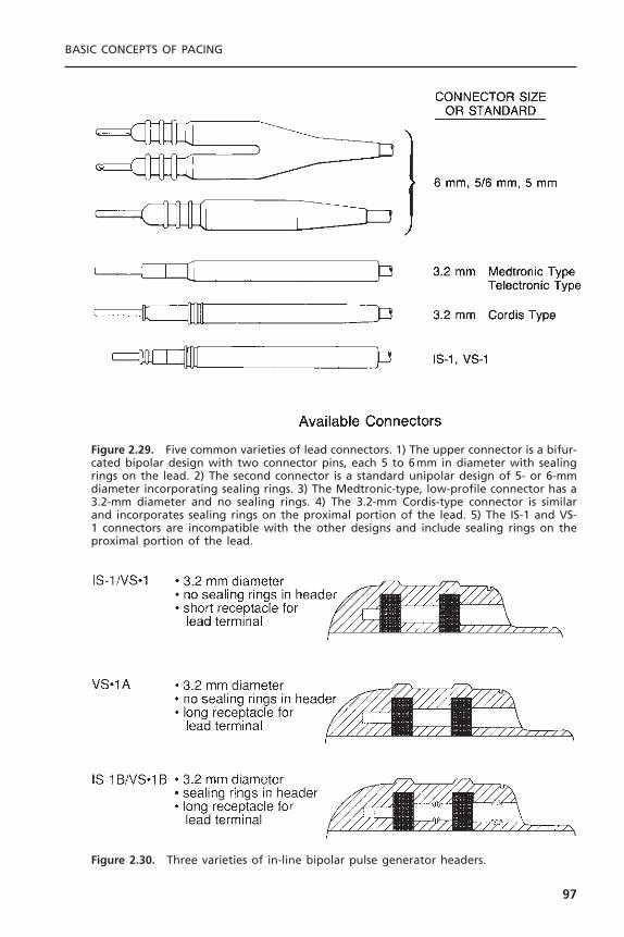
BASIC CONCEPTS OF PACING
97
Figure 2.29. Five common varieties of lead connectors. 1) The upper connector is a bifur-cated bipolar design with two connector pins, each 5 to 6mm in diameter with sealingrings on the lead. 2) The second connector is a standard unipolar design of 5- or 6-mmdiameter incorporating sealing rings. 3) The Medtronic-type, low-profile connector has a3.2-mm diameter and no sealing rings. 4) The 3.2-mm Cordis-type connector is similarand incorporates sealing rings on the proximal portion of the lead. 5) The IS-1 and VS-1 connectors are incompatible with the other designs and include sealing rings on theproximal portion of the lead.
Figure 2.30. Three varieties of in-line bipolar pulse generator headers.
venous pacing leads for cardiac resynchronization has led to another potentialconflict between the lead connector and pulse generators. Whereas the othermanufacturers offer cardiac venous leads with an IS-1 connector, Guidant man-ufacturers leads with an LV-1 connector that will only connect to a specializedLV-1 pulse generator (manufactured only by Guidant). This presents a potentialdifficulty at the time of pulse generator replacement.
Specialized Coatings to Prevent Tissue IngrowthBecause pacing and ICD leads may need to be extracted, newer leads are beingdesigned so that the trauma of lead extraction can be minimized.The first con-sideration is to make the lead isodiametric so that there are no ridges or areasof increased diameter along the lead that would increase the risk of removal. Anovel advance is the introduction of ePTFE (expanded polytetrafluoroethylene)coating over the ICD coils of the Guidant Reliance G leads. This coating pre-vents the ingrowth of tissue into the coil electrodes while having no significanteffect on the conduction of electrical energy. Such coatings are likely to mini-mize the risks of later lead extraction.
PULSE GENERATORSAll pulse generators presently used in permanent pacing systems have severalbasic functional elements that are critical to the operation of the device. Theseinclude a power source, an output circuit, a sensing circuit, and a timing circuit.Pulse generators also contain a telemetry coil for sending and receiving pro-gramming instructions and diagnostic information. In addition to these basicelements, almost all new pulse generators contain circuits for sensing the outputof an artificial, rate-adaptive sensor. The integrated circuit of most pulse gener-ators also contains the capability of storing information in memory—eitherread-only memory (ROM) or random access memory (RAM)—which can beused to process diagnostic data or alter the feature set of the device followingits implantation. In this section, the important aspects of each of these basic ele-ments of pulse generators are reviewed.
Power SourceThe power source of all pulse generators presently in use is a chemical battery.Modern pulse generators almost exclusively use lithium as the anodal elementand iodine as the cathodal element (Fig. 2.31).The energy provided by a chem-ical battery is generated by the transfer of electrons from the anodal element tothe cathodal element of the battery. In the case of lithium batteries, lithium isthe anodal element and provides the supply of electrons. The cathodal elementof the battery receives the electrons. In a lithium–iodine cell, iodine serves asthe cathodal element and accepts electrons from lithium. Poly-2-vinyl pyridineis combined with the cathodal element to assist in the transfer of electrons toiodine. At the battery terminals, the anode gives up electrons and is negativelycharged, and the cathode accepts electrons and is positively charged. Internally,
CARDIAC PACING AND ICDS
98
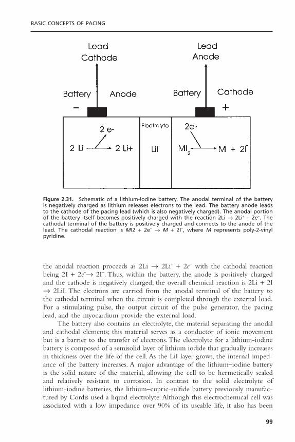
the anodal reaction proceeds as 2Li Æ 2Li+ + 2e- with the cathodal reactionbeing 2I + 2e-Æ 2I-. Thus, within the battery, the anode is positively chargedand the cathode is negatively charged; the overall chemical reaction is 2Li + 2IÆ 2LiI. The electrons are carried from the anodal terminal of the battery tothe cathodal terminal when the circuit is completed through the external load.For a stimulating pulse, the output circuit of the pulse generator, the pacinglead, and the myocardium provide the external load.
The battery also contains an electrolyte, the material separating the anodaland cathodal elements; this material serves as a conductor of ionic movementbut is a barrier to the transfer of electrons. The electrolyte for a lithium-iodinebattery is composed of a semisolid layer of lithium iodide that gradually increasesin thickness over the life of the cell. As the LiI layer grows, the internal imped-ance of the battery increases. A major advantage of the lithium–iodine batteryis the solid nature of the material, allowing the cell to be hermetically sealedand relatively resistant to corrosion. In contrast to the solid electrolyte oflithium-iodine batteries, the lithium–cupric-sulfide battery previously manufac-tured by Cordis used a liquid electrolyte. Although this electrochemical cell wasassociated with a low impedance over 90% of its useable life, it also has been
BASIC CONCEPTS OF PACING
99
Figure 2.31. Schematic of a lithium-iodine battery. The anodal terminal of the batteryis negatively charged as lithium releases electrons to the lead. The battery anode leadsto the cathode of the pacing lead (which is also negatively charged). The anodal portionof the battery itself becomes positively charged with the reaction 2Li Æ 2Li+ + 2e-. Thecathodal terminal of the battery is positively charged and connects to the anode of thelead. The cathodal reaction is MI2 + 2e- Æ M + 2I-, where M represents poly-2-vinyl pyridine.

associated with corrosion of the terminal feed-through and early failure. Thezinc-mercury battery used in early pulse generators contained sodium hydrox-ide as the electrolyte, a material that was corrosive and associated with thepotential for sudden failure. Zinc-mercury batteries were also characterized bythe production of hydrogen gas as a by-product of the battery reaction. Therequirement for the venting of hydrogen gas from the battery prevented her-metic sealing of the pulse generator and permitted the influx of tissue fluid,further increasing the risk of sudden failure.
The battery voltage depends on the chemistry of the cell. For example, thelithium-iodine cell generates approximately 2.8V at the beginning of its life.The lithium–silver-chromate cell generates 3.2 V and the lithium–thionyl-chloride cell produces 3.6V at beginning of life, whereas the lithium–lead-iodide cell has a voltage of only 1.9V. Because the voltage of each of these cellsis less than what may be required for chronic myocardial stimulation, a voltagemultiplier in the output circuit must be used to allow output pulses of greateramplitude than the cell voltage. If the lithium-iodine battery potential is 2.8V,how is it possible for a pacemaker to deliver an amplitude of 5V? There aretwo potential methods for delivering a stimulus with an amplitude that is greaterthan that generated by the chemical reaction of the battery.
First, the pacemaker could use two batteries placed in series. Using cellsin series increases the output voltage of the battery but does not increase batterycapacity. Electrochemical cells may also be connected in parallel to increasecapacity. However, cells in parallel do not generate an increased voltage. Thealternative method is to use the battery charge of two capacitors in parallel andthen to discharge the two capacitors to the lead in series. In this way a singlebattery with a potential of 2.8 V could generate 5.6 V with two capacitors, or8.4 V with three capacitors. The total capacitance (CT) of two capacitors (C1
and C2) charged in parallel is equal to CT = C1 + C2. Because the total charge(Q) is related to the voltage (V ) and capacitance (C ) of the capacitor by theequation Q = CV, a double amount of charge is drawn from the battery.However, when these two capacitors are then discharged in series onto the lead,the capacitance is given by the equation.
Thus, the discharge of these two capacitors in series results in a capaci-tance that is equal to one-half that for a single capacitor. Because an equalamount of charge must flow from each capacitor in series, the remaining voltageon the capacitor after discharge is Vf/2, where Vf is the final voltage. The netresult is that by programming the pacemaker to a voltage that is double thebattery voltage, the charge taken from the battery is equal to twice that deliv-ered to the lead and the total amount of charge drained from the batteryincreases fourfold.
The longevity of a battery is determined by several factors, including thechemical elements of the battery, the size of the battery, the amount of inter-
1 1 1
1 2CT C C= +
CARDIAC PACING AND ICDS
100

nal discharge, and the voltage decay characteristics of the cell. To maximizebattery life, the ideal electrochemical cell would have no internal discharge.However, batteries used for permanent pacemakers have been associated withinternal discharge of variable degrees. For example, the initial zinc-mercury cellswere associated with an internal rate of self-discharge of over 15% per year.Thelithium-iodine cell is associated with a low rate of self-discharge following theinitial reaction of lithium and iodine in the cell, generally less than 1% per yearin chronic use.
For a battery to be suitable for use in permanent pacemakers, the decaycharacteristics of the cell should be predictable (Fig. 2.32). The ideal batteryshould have a predictable fall in voltage near the end of life, yet provide suffi-cient service life after the initial voltage decay to allow time for the electivereplacement indicator to be detected and for replacement to be performed.Theearly zinc-mercury batteries were associated with a nearly constant cell voltageuntil end of life, when the voltage declined abruptly. These characteristics weregenerally unacceptable because of the difficulty of anticipating battery deple-tion. Lithium cells are associated with a more predictable behavior at end oflife. The lithium–silver-chromate cell is characterized by two distinct plateauphases of voltage, the first phase (3.2 V) representing approximately 70% of theservice life and a second phase of approximately 2.5 V. This two-phase decaycharacteristic is an attractive feature of this cell and allows a wide period inwhich to detect the elective replacement indicator.
Another battery that has been used for permanent pacemakers is thelithium–thionyl-chloride cell. This battery was associated with instances of anabrupt fall in battery voltage related to a sudden rise in cell impedance and
BASIC CONCEPTS OF PACING
101
Figure 2.32. Typical voltage decay characteristics of a lithium-iodine battery. At begin-ning of life, the lithium-iodine cell generates 2.8V. At end of useable life (90% deple-tion), the battery voltage decreases to approximately 1.8V.
unexpected end-of-life behavior.The voltage produced by a lithium-iodine cellis inversely related to the internal battery impedance. The internal impedanceof the battery increases with the thickness of the lithium-iodide electrolyte layer,from less than 1kohm at the beginning of life to over 15kohm at the extremeend of life. The voltage generated by the cell declines almost linearly from theinitial value of 2.8 V to 2.4 V at approximately 90% of the useable battery life.Following this, the voltage declines exponentially to 1.8 V at the end of life.The magnet-related pacing rate of the pulse generator is related to the cellvoltage, usually declining once the voltage falls below 2.4 V. The end-of-lifeindicator of pulse generators is usually signaled by a decrease in the magnet-related pacing rate to a fixed percentage of the beginning-of-life rate. Unfortu-nately, the end-of-life magnet rate is variable between manufacturers andbetween models. Some manufacturers signal the end of life by a two-stepprocess, with an initial decrease in the magnet rate to an intermediate value fol-lowed by a stepwise decrease in rate to a second, lower value in association witha change in pacing mode, such as from DDD to VVI. In addition to a decreasein the magnet rate, the cell impedance of many pulse generators can be directlytelemetered from the device, allowing a more accurate estimation of the useableservice life. Some manufacturers also include an automatic increase in the pulseduration of the output circuit so that the total energy of the pulse deliveredremains constant. Although the output energy may remain constant by thestretching of the pulse duration, loss of capture will occur if the stimulus voltagefalls below rheobase.
The useable service life of a pulse generator not only depends on the char-acteristics of the battery, but is greatly influenced by the current drain of theintegrated circuit, the amplitude and duration of the output pulse, the frequencyof stimulation, the total impedance of the pacing lead, and the additional energyrequired to monitor and generate the output of a rate-adaptive sensor. Advancesin the design of integrated circuits have greatly minimized the static currentdrain required to operate the circuit to less than 2mA. The major source ofcurrent drain for the present generation of pulse generators is the output pulse.Thus, the amplitude, duration, and frequency of stimulating pulses are majorcontributors to the life of the power source. The pacing impedance is anothercritical influence on the current drain of the output pulse. Advances in pacingleads that have improved pulse generator longevity while providing an adequatesafety margin include the use of electrodes with steroid elution, high electrode-tissue impedance, and low polarization. With the introduction of these high-performance leads, the nominal output energy has been significantly reduced.The addition of automatic threshold tracking and capture verification also holdsthe potential to increase pulse generator longevity by optimizing the energy ofthe stimulating pulse for each patient.
Output CircuitsThe output pulse of the pulse generator is generated from the discharge of acapacitor to the anode and cathode of the pacing leads.The output capacitor is
CARDIAC PACING AND ICDS
102
charged from the battery at a relatively slow rate to the programmed outputvoltage. Because the battery voltage of lithium–iodine cells is approximately 2.8V, delivery of a stimulus of amplitude greater than this requires the use of avoltage multiplier. The voltage multiplier involves charging more than onecapacitor from the battery. For example, if a stimulus voltage of 5.6 V is pro-grammed, two capacitors must be charged from the battery in parallel and dis-charged in series.The cost of doubling the output voltage is a fourfold increasein current drain from the battery. If the stimulus amplitude is programmed to8.4 V (three times the voltage of a lithium-iodide cell), three capacitors mustbe charged. In this case, a threefold increase in stimulus voltage results in a nine-fold increase in current drain from the battery, markedly shortening battery life.
Output Pulse Waveforms: Most pulse generators used for permanent cardiacpacing deliver a capacitively coupled, constant-voltage pulse of programmableduration. When the fully charged capacitor is discharged, the resulting voltageat the leading edge of the pulse is independent of the pacing impedance.However, the trailing edge of the pulse is less than that of the leading edge,with the magnitude of the voltage drop being a function of the pacing imped-ance (Fig. 2.33). Because the capacitor stores a charge of fixed quantity, thegreater the current flow, the smaller the charge (and voltage) remaining on thecapacitor at the end of the pulse.Therefore, the lower the impedance, the greaterthe current delivered and the greater the drop in voltage from leading edge totrailing edge during the pulse. Thus, even though the term constant voltage isused to describe the stimulus waveform of permanent pacemakers, in reality theoutput voltage of the pulse is not constant from beginning to end.
Constant-current generators are no longer being implanted for permanentpacing, though a few pulse generators manufactured by Cordis are still in service.However, constant-current pulse generators are typical of many external pacingsystems. The constant-current pulse is typically flat, with little or no change incurrent from leading edge to trailing edge. However, as the polarization imped-ance rises during the pulse, the resulting voltage must also rise proportionallyto maintain the current at a constant level. Although either constant-current orconstant-voltage pulse generators are capable of providing reliable pacing in thevast majority of clinical circumstances, at extremely high lead impedances thevoltage required to maintain a constant-current pulse may exceed the capabil-ities of the battery.
The output waveform of the pulse generator is followed by a low-amplitude, long-duration wave of opposite polarity known as the afterpotential.The afterpotential is caused by polarization at the electrode–tissue interface andis dependent on the stimulus amplitude and duration. The afterpotential is alsoinfluenced by the polarization characteristics of the electrode. Afterpotentialsmay be inappropriately sensed by the sensing circuit if the stimulus amplitudeand pulse duration are great and the sensing threshold is low. To reduce theafterpotential, the output circuit of some manufacturers incorporates a fastrecharge pulse, during which the electrode polarity is reversed for a short period
BASIC CONCEPTS OF PACING
103
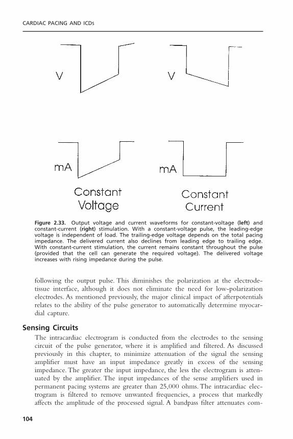
following the output pulse. This diminishes the polarization at the electrode-tissue interface, although it does not eliminate the need for low-polarizationelectrodes. As mentioned previously, the major clinical impact of afterpotentialsrelates to the ability of the pulse generator to automatically determine myocar-dial capture.
Sensing CircuitsThe intracardiac electrogram is conducted from the electrodes to the sensingcircuit of the pulse generator, where it is amplified and filtered. As discussedpreviously in this chapter, to minimize attenuation of the signal the sensingamplifier must have an input impedance greatly in excess of the sensing impedance. The greater the input impedance, the less the electrogram is atten-uated by the amplifier. The input impedances of the sense amplifiers used inpermanent pacing systems are greater than 25,000 ohms. The intracardiac elec-trogram is filtered to remove unwanted frequencies, a process that markedlyaffects the amplitude of the processed signal. A bandpass filter attenuates com-
CARDIAC PACING AND ICDS
104
Figure 2.33. Output voltage and current waveforms for constant-voltage (left) and constant-current (right) stimulation. With a constant-voltage pulse, the leading-edgevoltage is independent of load. The trailing-edge voltage depends on the total pacingimpedance. The delivered current also declines from leading edge to trailing edge. With constant-current stimulation, the current remains constant throughout the pulse(provided that the cell can generate the required voltage). The delivered voltageincreases with rising impedance during the pulse.

ponents of the electrogram on either side of the center frequency (the frequencywith least attenuation) (Fig. 2.34). The bandpass filters of different manufactur-ers vary significantly with regard to center frequency (from approximately 20to 40Hz), so intracardiac electrograms measured with a pacing system analyzerof one manufacturer may produce considerably different electrogram amplitudesthan will the pulse generator sensing amplifier of another manufacturer. It isalso somewhat difficult to compare the sense amplifiers of different manufac-turers because the shape of the test waveform has an important influence onthe amplitude of the filtered electrogram, such that square-wave and sinusoidaltest pulses may produce frequency attenuation spectra that differ from those ofintracardiac electrograms. Following filtering of the intracardiac signal, theprocessed signal is compared with a reference voltage to determine if the signalexceeds a threshold detection level. Signals with amplitude greater than the sen-sitivity threshold level are sensed as intracardiac events, whereas signals of loweramplitude are discarded as noise. Signals that exceed the threshold level aremarked by an output voltage pulse that is sent to the timing circuit.
Permanent pacemakers also contain noise reversion circuits that change thepulse generator to an asynchronous pacing mode when the sensing thresholdlevel is exceeded at a rate faster than the noise reversion rate. The noise rever-sion mode prevents inhibition of pacing in the presence of electromagnetic
BASIC CONCEPTS OF PACING
105
Figure 2.34. Signal processing with bandpass filtering of a sine-squared test waveformby a ventricular sensing amplifier. The curve denotes the signal amplitude required to bedetected by the sensing amplifier with a threshold sensitivity value of 2.5mV. Note thatthe amplitude of the signal that is needed for appropriate sensing is markedly increasedat frequencies below and above the center frequency.

interference. The electronic circuitry of the pulse generator must also be pro-tected from damage caused by overwhelming electrical energy generated in theclinical environment. The input voltage to the sensing amplifier is limited by aZener diode that is designed to protect the integrated circuit from high exter-nal voltages such as may occur during defibrillation shocks or electrocautery.When the input voltage carried by the pacing leads exceeds the Zener voltage,the excess energy is shunted back to the myocardium through the leads. In addi-tion to these features, which are designed to manage external electromagneticinterference, the sensing amplifier must prevent the detection of unwantedintracardiac signals such as far-field R waves in the atrial electrogram, after-potentials, T waves, and retrogradely conducted P waves.
The potential for inappropriate inhibition of the ventricular output of adual chamber pacemaker by far-field ventricular sensing of the atrial pacingstimulus or its afterpotential can be effectively reduced by the use of a ventric-ular blanking period. During the ventricular blanking period, the ventricularsensing amplifier is turned off immediately following the atrial pacing pulse.Although the blanking period has been quite effective in decreasing the fre-quency of ventricular crosstalk (inappropriate inhibition of ventricular pacingby far-field atrial pacing stimuli), several manufacturers also provide a nonphys-iologic AV delay with delivery of a ventricular pacing pulse on sensing a ven-tricular event early in the AV interval. The inappropriate detection of intracardiacsignals is also managed by the use of sensing refractory periods, during whichthe sense amplifier is not responsive to events such as T waves or retrogradelyconducted P waves. The initial portion of the refractory period is a blankingperiod during which the sense amplifier is totally insensitive to electrical signals.
The remainder of the refractory period is typically a noise-sampling period.Events in this portion of the refractory period do not reset the timing circuitbut initiate a new blanking period. Although sensing refractory periods areextremely effective for the management of unwanted signals, there are relativedisadvantages to this approach, such as the inability of a DDD pacing system totrack rapid atrial rates when a prolonged atrial refractory period is required tomanage retrograde ventriculoatrial conduction. Newer pacing systems thatincorporate variable refractory periods that change in proportion to the outputof a metabolic sensor are likely to reduce the importance of these disadvantages.
Timing CircuitsThe pacing cycle length, sensing refractory and alert periods, pulse duration,and AV interval are precisely regulated by the timing circuit of the pulse gen-erator. The timing circuit of a pulse generator is a crystal oscillator that gener-ates a very accurate signal with a frequency in the kHz range. The output ofthe crystal oscillator is sent to a digital timing and logic control circuit thatoperates internally generated clocks at divisions of the oscillator frequency. Theoutput of the logic control circuit is a logic pulse that triggers the output pacingpulse, the blanking and refractory intervals, and the AV delay.The timing circuitalso receives input from the sense amplifier to reset the escape intervals of an
CARDIAC PACING AND ICDS
106

inhibited pacing system or trigger initiation of an AV delay for triggered pacingmodes.The pulse generator also contains a rate-limiting circuit that prevents thepacing rate from exceeding an upper limit in the case of a random componentfailure.This runaway protection rate is typically in the range of 180 to 200ppm.
Telemetry CircuitsProgrammable pulse generators have the capability of responding to radiofre-quency signals emitted from the programmer as well as sending information in the reverse direction, from the pulse generator to the programmer.The pulsegenerator is capable of both transmitting information from a radiofrequencyantenna and receiving information with a radiofrequency decoder. Telemetryinformation may be sent as radiofrequency signals or as a pulsed magnetic field.Information that is sent from an external programmer to the pulse generator issent in coded programming sequences with a preset frequency spectrum. Mostpulse generators require the radiofrequency signal to be pulsed with a specificfrequency in a sequence that is typically 16 pulses in duration.Thus the radiofre-quency signal is quite precise, decreasing the likelihood of inappropriate alter-ation of the program by environmental sources of radiofrequency energy ormagnetic fields. This characteristic also prevents the programmers of one man-ufacturer from programming the pulse generator of another. The detectedtelemetry bursts from the programmer are sent as digital information from theradiofrequency demodulator to the telemetry control logic circuit of the pulsegenerator. This logic circuit also provides for properly timed pulses to be sentfrom the antenna of the pulse generator to the programmer. Real-time telemetryis the term used to describe the capability of a pulse generator to transmitinformation to the programmer regarding measurements of pulse amplitude andduration, lead impedance, battery impedance, and delivered current, charge, andenergy. These measurements may provide useful information for troubleshoot-ing pacing systems. The pulse generator may also allow telemetry of intracar-diac electrograms and timing circuit markers that can be extremely valuable forthe evaluation of sensing (see Chapters 7 and 10).
MicroprocessorsMicroprocessors have become the standard control circuits of implantable pacemakers and ICDs. Microprocessors have several advantages over older inte-grated circuits, including a far greater circuit density and greatly reduced currentdrain. Microprocessors also allow very sophisticated algorithms, requiring mul-tiple calculations to be incorporated into implantable devices, and have vastlyincreased data storage. The microprocessor can respond to changes in program-ming instructions that allow functions to be added or changed after implanta-tion. The integrated circuit of pulse generators may contain both ROM andRAM.
ROM (typically 1 to 2 kilobytes of 8 to 32 bits) is used to guide thesensing and output circuits. Devices with 8- or 16-bit processors usually requireseveral clock cycles to decode an instruction from memory.The processors oper-
BASIC CONCEPTS OF PACING
107
ating with larger instruction words (such as 32 bits) may load and execute aninstruction in a single clock cycle, improving the efficiency of the repetitivetasks that are required for pacing and sensing.
In addition, RAM is used to store diagnostic information regarding pacingrate, intrinsic heart rates, and sensor output. The amount of RAM that isincluded in the pulse generator varies between models and manufacturers. Theamount of RAM in modern pulse generators is rapidly increasing and willincrease the amount of diagnostic information that can be stored in the pulsegenerator. Such data include histograms of paced and intrinsic heart rate, sensorfunction, trends of heart rate and sensor function over time, storage of intra-cardiac electrograms from episodes of high atrial or ventricular rates, and mode-switching events. The rapidly expanding diagnostic capabilities of pacemakerswill allow improved assessment of the physiologic condition of the patient.Thus,information may be stored that relates to heart rate variability, respiration, intra-cardiac pressure, patient activity, lung water, and arrhythmias.
Almost all manufacturers offer fully RAM-based pulse generators. Thereare several important advantages to microprocessor-based pacemakers, includingdecreased production costs for an entire product line, increased flexibility toupgrade features in subsequent pacemaker models, and the capability for down-loading new features into previously implanted pacemakers by telemetry. It is important to emphasize that the microprocessors used in permanent pace-makers must be custom designed to minimize current drain and operate witha lithium-iodine battery.Thus, a microprocessor that is used in a microcomputerand has access to a virtually unlimited power supply (AC current operating at110V) would not be feasible for inclusion in a permanent pacemaker.
RATE-ADAPTIVE SENSORSWidespread appreciation of the importance of rate modulation in the augmen-tation of cardiac output with exercise has led to the development of a varietyof physiologic sensors. Although the normal sinus node may be an ideal rate-adaptive sensor for many patients who require pacemakers, the frequent occur-rence of sinus node dysfunction and atrial fibrillation in clinical practice limitsthe applicability of atrial sensing for reliably modulating pacing rate in manyindividuals. Thus, artificial sensors that correlate with the level of metabolicdemand either directly or indirectly have assumed increased importance in thedesign and application of permanent pacing systems. In this section, the designconsiderations of these sensors are discussed. For practical concerns, two majorrate-adaptive sensors have come to dominate the pacing market: accelerometersand minute ventilation. Although there have been a host of other potentialsensors, including the continued use of the QT interval and intracardiac imped-ance, only accelerometers and minute ventilation sensors have achieved wide-spread acceptance for standard pacemakers.
The ideal rate-adaptive pacing system should provide pacing rates that areproportional to the level of metabolic needs.The speed of change in the pacing
CARDIAC PACING AND ICDS
108

rate should be similar to that of the sinus node. The ideal sensor demonstratessensitivity and specificity. It should demonstrate sensitivity to both exercise- andnon-exercise-related changes, such as mental stress. Specificity is demonstratedby the failure of the sensor to be affected by stimuli that should not cause anincrease in pacing rate.
Multiple technical considerations are important in the implementation ofthe sensor. These include the stability of the sensor and the size of the sensor,as well as its biocompatibility and the ease of its programming. Excessive energyconsumption by a sensor will limit the life span of the pulse generator. Sensorsthat are large or require the placement of additional electrodes or a new typeof electrode may present a technical problem. The response of the sensor isdetermined by its intrinsic properties in response to stimuli, by the algorithmused to relate changes in the sensed parameter to changes in paced heart rate,and by the ease and way it is programmed.
Activity Sensors and AccelerometersRate-adaptive pacing systems that detect mechanical vibration are based on theclinical association of increasing body motion with increasing levels of exercise.These devices are designed to detect low-frequency vibrations in the range ofthe resonant frequency of the human body (approximately 4Hz). A piezoelec-tric ceramic crystal functioning as a strain gauge is bonded to the inside of thepulse generator case or to the circuit board (Fig. 2.35). As the ceramic crystalflexes and deforms in response to mechanical vibration or pressure, an electriccurrent is generated. The magnitude of the electric current from the crystal isrelated to the frequency and amplitude of vibrations. The output of the sensoris processed electronically and used to modulate changes in pacing rate.
Early motion-sensitive pacing systems simply counted the occurrence ofsensor output exceeding a programmable threshold level (Fig. 2.36, top).97,98
BASIC CONCEPTS OF PACING
109
Figure 2.35. Schematic of two motion-sensing, rate-adaptive pacing systems. Top: Anaccelerometer (piezoelectric crystal) is mounted on the circuit board of the pulse gener-ator. Bottom: The alternative sensor location, with the piezoelectric crystal mounted onthe inside of the pulse generator case. (Courtesy of Intermedics, Inc.)
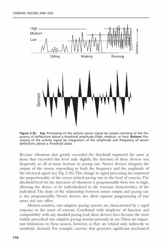
Because vibrations that greatly exceeded the threshold registered the same asthose that exceeded this level only slightly, the function of these devices wasfrequently an all-or-none increase in pacing rate. Newer devices integrate theoutput of the sensor, responding to both the frequency and the amplitude ofthe electrical signal (see Fig. 2.36).This change in signal processing has improvedthe proportionality of the sensor-related pacing rate to the level of exercise.Thethreshold level for the detection of vibrations is programmable from low to high,allowing the device to be individualized to the resonant characteristics of theindividual.The slope of the relationship between sensor output and pacing rateis also programmable. Newer devices also allow separate programming of rateonset and rate offset.
Motion-sensitive, rate-adaptive pacing systems are characterized by a rapidresponse to the onset of exercise. Combined with simplicity of function andcompatibility with any standard pacing lead, these devices have become the mostwidely prescribed rate-adaptive pacing systems presently in use.There are impor-tant limitations to these sensors, however, as they are related only indirectly tometabolic demand. For example, exercise that generates significant mechanical
CARDIAC PACING AND ICDS
110
Figure 2.36. Top: Processing of the activity sensor signal by simple counting of the fre-quency of deflections above a threshold amplitude (high, medium, or low). Bottom: Pro-cessing of the activity signal by integration of the amplitude and frequency of sensordeflections above a threshold value.
vibration (such as walking or arm motion) leads to a greater rate increase thanexercise that produces less motion (such as bicycling). Similarly, the pacing rateproduced by descending stairs is typically greater than that produced by climb-ing stairs.99 In addition, these sensors are susceptible to environmental noise fromvibrations produced by transportation or direct pressure over the pulse genera-tor. Finally, these sensors respond poorly to some types of exercise (e.g., swim-ming, isometric exercise).
Because of these limitations of activity sensors, body motion is nowdetected by the use of accelerometers. Acceleration sensors use either piezo-electric or piezoresistive materials.100 The piezoelectric accelerometer is mountedon the hybrid circuitry in the pulse generator rather than bonded to the pulsegenerator case and has become the standard method for detection of bodymotion. This allows the accelerometer to be mechanically insulated from thecase, preventing increases in pacing rate as a result of simple pressure on thepulse generator. As the patient moves in the anterior-posterior axis, the mass ofthe accelerometer deflects in proportion to the change in velocity (acceleration= dV/dt). Accelerometers that are piezoelectric generate an electrical potentialas a result of deformation of the piezoceramic material. In contrast, piezoresis-tive accelerometers measure changes in electrical resistance that occur withmechanical deformation of the sensor and require a somewhat greater currentdrain to power the sensor.
Although motion of the body during walking or bicycling occurs in boththe anterior-posterior and vertical axes, exercise workload is more proportionalin the anterior-posterior axis than in the vertical axis. Because accelerometerstend to detect acceleration in the anterior–posterior axis to a greater extent thanin the vertical axis, these sensors offer the potential for greater proportionalityof response than do activity sensors. Accelerometers have been shown to besomewhat less susceptible to excessive rate increases during descending stairsthan activity sensors. Accelerometers have also been demonstrated to produce arate response that is closer to the expected behavior of the sinus node duringbicycle exercise than has been observed with activity sensors. In general,accelerometers offer rate modulation that is somewhat more proportional toexercise workload than is usual with activity sensors. As a result, accelerometershave largely replaced activity sensors for rate-adaptive pacing.
Because accelerometers have a constant coupling mass of the sensor that isindependent of the body, these devices offer a more predictable range ofresponses during exercise than do activity sensors. In fact, the acceleration signalsthat are recorded with accelerometers are remarkably consistent among indi-viduals who vary in body weight, age, or physiologic condition. These devicesalso have improved resolution (ability to detect small changes in motion) as com-pared with activity sensors. The raw accelerometer signal is rectified and inte-grated to produce a value that represents the energy content of the signal.Because the frequency range of the accelerometer signal associated with exer-cise is known to have a maximal amplitude less than 4Hz, the signal can be fil-tered to remove external noise, which typically has maximal amplitude in the
BASIC CONCEPTS OF PACING
111
range of frequencies between 10 and 50Hz. The typical accelerometer isdesigned to respond to frequencies between 0.5 and 10Hz.This ability to filterunwanted signals is an advantage of accelerometers as compared with activitysensors, which are less able to discriminate body motion from external noise.
The most characteristic attribute of accelerometers is their ability torespond rapidly to the onset of exercise. The interval from the onset of exer-cise to an increase in sensor energy is often instantaneous. For the accelerom-eter to modulate the pacing rate, the sensor energy must be converted to adesired pacing rate. For any given sensor energy, the desired pacing rate must becalculated from the lower pacing rate, the upper sensor rate, the upper trackingrate, the rate adaptive slope, and any rate-smoothing or mode-switching con-straints. In addition, reaction and decay constants, which may or may not beprogrammable, translate the time required to change the actual pacing rate tothe desired pacing rate.The sensor slope parameter determines the rate of changein pacing rate that will occur for a given change in the accelerometer signalenergy. For a given change in sensor energy the greater the programmed slope,the greater the pacing rate that will be calculated. However, the effect of theupper sensor rate on the pacing rate that will be achieved at any given level ofexercise and slope setting should be emphasized. For example, programming themaximum sensor rate from 120bpm to 160bpm will have a marked influenceon the rate adaptive function of the pacemaker that is at least as important asthe slope value that is programmed.
Accelerometers have been demonstrated to provide a more physiologic rateadaptation than activity sensors can provide during treadmill or bicycle exercisetesting.101,102 The response to walking downstairs has been far more physiologicwith accelerometers than with activity sensors.102 Newer pacemakers offer auto-matic adjustment of the rate adaptive slope of the accelerometer by comparingthe rate-adaptive histograms observed over time to a set of expected responses.If the accelerometer provides pacing rates that exceed the target rates more fre-quently than expected, the slope parameter is reduced. If the pacing rate doesnot reach the target rate the slope value is gradually increased until an expectedtarget rate is achieved. Although the ability of these algorithms to achieve aphysiologic rate modulation during exercise may not be ideal in all patients,these algorithms tend to prevent extremes of overpacing or underpacing in thepopulation of pacemaker patients.
The major advantage of accelerometers over activity sensors is that theycan be applied to any pacing lead, regardless of the polarity or electrical integrity.They have a proven ability to provide a rapid heart rate response to the onsetof exercise, and there is now widespread clinical experience with these devices.For these reasons accelerometers are the most commonly prescribed rate-adaptive sensors implanted.
Minute Ventilation SensorsRespiratory rate (RR), tidal volume (TV), and minute ventilation (the productof these two parameters) increase in proportion to changes in carbon dioxide
CARDIAC PACING AND ICDS
112
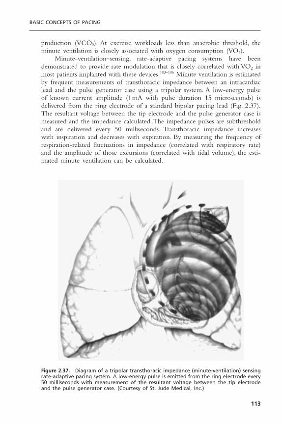
production (VCO2). At exercise workloads less than anaerobic threshold, theminute ventilation is closely associated with oxygen consumption (VO2).
Minute-ventilation–sensing, rate-adaptive pacing systems have beendemonstrated to provide rate modulation that is closely correlated with VO2 inmost patients implanted with these devices.103–106 Minute ventilation is estimatedby frequent measurements of transthoracic impedance between an intracardiaclead and the pulse generator case using a tripolar system. A low-energy pulseof known current amplitude (1mA with pulse duration 15 microseconds) isdelivered from the ring electrode of a standard bipolar pacing lead (Fig. 2.37).The resultant voltage between the tip electrode and the pulse generator case ismeasured and the impedance calculated.The impedance pulses are subthresholdand are delivered every 50 milliseconds. Transthoracic impedance increases with inspiration and decreases with expiration. By measuring the frequency ofrespiration-related fluctuations in impedance (correlated with respiratory rate)and the amplitude of those excursions (correlated with tidal volume), the esti-mated minute ventilation can be calculated.
BASIC CONCEPTS OF PACING
113
Figure 2.37. Diagram of a tripolar transthoracic impedance (minute-ventilation) sensingrate-adaptive pacing system. A low-energy pulse is emitted from the ring electrode every50 milliseconds with measurement of the resultant voltage between the tip electrodeand the pulse generator case. (Courtesy of St. Jude Medical, Inc.)
The transthoracic impedance signal is a complex parameter that is influ-enced by several factors. However, the transthoracic impedance is most closelyrelated to the volume and resistivity of blood in the right heart chambers andsystemic venous system.The impedance signal fluctuates in response to both res-piration and cardiac motion (right ventricular ejection). The impedance signalmay also change with thoracic motion due to arm movements.To minimize thecardiac-related component of the impedance signal, low-pass filtering of fre-quencies greater than 48 to 60Hz is performed. A potential problem of thisapproach is that respiratory rates greater than 48 to 60 breaths per minute, whichmay be observed in children, may be inappropriately sensed.
The impedance signal is processed by comparing the average impedancevalues accumulated over two periods (1 minute and 1 hour). When the short-term average (1 minute) exceeds the long-term average (1 hour), the pacingrate is increased.The slope of the relationship between changes in minute ven-tilation and pacing rate is a programmable parameter. Because the initial minute-ventilation pacing systems decreased the paced cycle length linearly with respectto the minute-ventilation signal, the sensor was characterized by a relatively slowonset of rate modulation. Newer generations of devices offered a linear rela-tionship between pacing rate and minute ventilation, improving the rate-adaptive algorithm and the initial response to exercise. In general, the minute-ventilation sensor is characterized by a highly proportional relationshipto metabolic demand over a wide variety of exercise types. The most recentgeneration of minute-ventilation sensors have further refined the relationbetween heart rate and minute ventilation by the use of different slopes belowand above the anaerobic threshold. Because minute ventilation normallyincreases out of proportion to the heart rate and oxygen consumption at highexercise workloads (above the anaerobic threshold), newer sensors decrease theheart rate/minute-ventilation slope at high levels of exercise. These refinementshave made the minute-ventilation sensor very physiologic. By allowing a steeperslope at low levels of exercise and a flatter slope at high levels of exercise, therate adaptation that can be achieved is greatly improved. The steeper slope atlow minute-ventilation levels allows the sensor to respond rapidly to the onsetof exercise. By reducing the slope at high minute-ventilation levels, overpacingis prevented.
Minute-ventilation sensing has been combined with both activity sensorsand accelerometers to improve the rate adaptive response to exercise.107 Earlypacemakers that combined activity and minute-ventilation sensors provided ratemodulation by allowing the fastest of these sensors to control the pacing rate.An advantage of this combination of sensors is the ability to separately programthe upper rate of each sensor. Thus, the activity sensor could be programmedto provide a very rapid increase in pacing rate at the onset of exercise, yetprevent excessive increases in rate by limiting the maximum activity rate. Afterminute ventilation increases during more sustained exercise, the rate responsecan be controlled by the minute-ventilation sensor. The clinical utility of thissensor combination has been demonstrated in a multicenter trial.
CARDIAC PACING AND ICDS
114
Minute-ventilation pacemakers generally require the use of a bipolar pacinglead to measure transthoracic impedance, limiting the use of this sensor inpatients with previously implanted pacing leads. However, DDDR pacingsystems manufactured by ELA Medical (Talent II) use the atrial lead to sensethe minute-ventilation signal. Although a bipolar atrial lead is required for thisdevice, a unipolar ventricular lead may be used. This device offers continuousself-modulation of the rate-adaptive slope based on a rolling trend of minute-ventilation signals. The ELA Talent II pacemaker allows minute ventilation tobe determined with a unipolar lead. The Guidant Pulsar Max and MedtronicKappa 400 series pacemakers have combined minute-ventilation and accelerom-eter sensors with blending of the sensor output to modulate pacing rate.Although providing quite different rate adaptive algorithms, both of thesedevices emphasize the accelerometer at low levels of exercise and the minute-ventilation sensor at high levels of exercise. Both devices also incorporate a cross-checking feature of the sensors such that overpacing in response to false-positivesensor activation. These devices also automatically adjust the rate adaptive slopeof the sensors by comparing the pacing rate achieved to an expected sensortarget rate or histogram profile.
QT IntervalThe intracardiac QT interval has been demonstrated to shorten with exerciseor sympathetic tone and to lengthen at rest.The QT interval also shortens withincreasing pacing rate and lengthens at slow heart rates.The QT interval is mea-sured from the onset of the pacing stimulus to the apex of the T wave in theintracardiac ventricular electrogram. Although the QT interval varies widelyamong individuals, it is quite consistent in an individual at rest. The QT inter-val can be markedly influenced by medications or electrolyte concentrations,however. Initial QT-sensing pacing systems suffered from a high incidence of Twave undersensing and degradation of the ventricular electrogram over time. Inaddition, electrodes with high polarization properties were associated with largeafterpotentials that interfered with accurate measurement of the QT interval.These problems were significantly improved by the addition of a fast-rechargepulse that minimized afterpotentials and by changes in the T wave filter.
The QT-pacing system includes an absolute refractory period of 250 mil-liseconds, which is followed by a programmable T wave sensing window (250to 450 milliseconds). A subthreshold marker pulse that is visible on the surfaceelectrocardiogram is useful for confirming appropriate T wave sensing. Furtherimprovements in this sensor have involved the use of a curvilinear slope thatimproves the initial rate response to the onset of exercise. Automation of theslope measurement has also improved the function of this sensor and reducedthe time required for calibration of the pacemaker. Disadvantages of the QTsensor involve the requirement for a low-polarization electrode, potentiallycomplex programming, and the fact that the T wave can be reliably sensed onlywith paced beats. The potential advantages of this sensor are its responsivenessto emotional factors and the lack of a specialized lead. It is also clear that the
BASIC CONCEPTS OF PACING
115
function of the sensor underwent continuous and significant refinement in therate-adaptive algorithm. The disadvantages of the QT sensor have been largelyovercome by combining this sensor with an activity sensor (Vitatron Diamond).This dual-sensor pacing system allows a programmable blending of sensorresponse to modulate pacing rate. Although this sensor has been reliable andeffective, its market share has been relatively small.
Other SensorsOther sensors that have been demonstrated to provide clinically acceptable ratemodulation include central venous temperature, mixed venous oxygen satura-tion, right ventricular dP/dt, peak endocardial acceleration, and intracardiacimpedance. Each of these sensors has been demonstrated to have highly physi-ologic rate response characteristics. Nevertheless, the requirement for a special-ized pacing lead has hindered the widespread acceptance of most of theseproducts.
REFERENCES1. Hodgkin AL, Huxley AF. A quantitative description of membrane current and its
application to conduction and excitation in nerves. J Physiol (Lond) 1952;117:500–544.
2. Grant AO. Evolving concepts of cardiac sodium channel function. J CardiovascElectrophysiol 1990;1:53–67.
3. Cohen CJ, Bean BP, Tsien RW. Maximal upstroke velocity (Vmax) as an index ofavailable sodium conductance: comparison of Vmax and voltage clamp measure-ments of INa in rabbit Purkinje fibers. Circ Res 1984;54:636–651.
4. Bodewei R, Hering S, Lemke B, et al. Characterization of the fast sodium currentin isolated rat myocardial cells: simulation of the clamped membrane potential.J Physiol (Lond) 1982 Apr; 325:301–315.
5. Angelides KJ, Nutter TJ. Mapping the molecular structure of the voltage-dependent sodium channel. J Biol Chem 1983;258:11958–11967.
6. Noda M, Ikeda T, Suzuki H, et al. Expression of functional sodium channels fromcloned cDNA. Nature 1986;322:826–828.
7. Tsien RW. Calcium channels in excitable cell membranes. Ann Rev Physiol1983;45:341–358.
8. Tsien RW, Hess P, McCleskey EW, et al. Calcium channels: mechanisms of selec-tivity permeation and block. Ann Rev Biophys Biochem 1987;16:265–290.
9. Hume JR, Giles W. Ionic currents in single isolated bullfrog atrial cells. J GenPhysiol 1983;81:153–194.
10. Hume JR, Giles W, Robinson K, et al. A time and voltage dependent K current in single cardiac cells from bullfrog atrium. J Gen Physiol 1986;88:777–798.
11. Brown HF, DiFrancesco D, Noble SJ. How does adrenalin accelerate the heart?Nature 1979;280:235–236.
12. DiFrancesco D, Ferroni A, Mozzanti M, et al. Properties of the hyperpolarizingactivated current (if ) in cells isolated from the rabbit sinoatrial node. J Physiol1986;377:61–88.
CARDIAC PACING AND ICDS
116

13. DeMello WC. Intracellular communication in cardiac muscle. Circ Res 1982;51:1–9.
14. Barr L, Dewey MM, Berger W. Propagation of action potentials and the structureof the nexus in cardiac muscle. J Gen Physiol 1965;48:797–823.
15. Walton MK, Fozzard HA. Experimental study of the conducted action potentialin cardiac Purkinje strands. Biophys J 1983;44:1–8.
16. Spach MS, Miller WT III, Geselowitz DB, et al.The discontinuous nature of prop-agation in normal canine cardiac muscle. Evidence for recurrent discontinuities ofintracellular resistance that affect the membrane currents. Circ Res 1981;48:39–54.
17. Spach MS, Dolber PC, Heidlage JR, et al. Propagating depolarization in anisotropichuman and canine cardiac muscle: apparent directional differences in membranecapacitance. A simplified model for selective directional effects of modifying thesodium conductance on Vmax, tau foot, and the propagation safety factor. CircRes 1987;60:206–219.
18. Inoue H, Zipes DP. Conduction over an isthmus of atrial myocardium in vivo: apossible model of Wolff-Parkinson-White syndrome. Circulation 1987;76:637–647.
19. Winfree AT.The electrical thresholds of ventricular myocardium. J Cardiovasc Elec-trophysiol 1990;1:393–410.
20. Irnich W. The fundamental law of electrostimulation and its application to defib-rillation. Pacing Clin Electrophysiol 1990;13:1433–1477.
21. Lapicque L. Définition expérimentale de l’excitabilité. Soc Biol 1909;77:280–283.
22. Hoorweg L. Über die elektrische nerve merregung. Pflugers Arch Physiol1892;52:87–99.
23. Weiss G. Sur la possibilité de rendre comparable entre eux les apparels servant al’excitation électrique. Arch Ital Biol 1901;35:413–446.
24. Blair HA. On the intensity–time relations for stimulation by electric currents.J Gen Physiol 1932;15:709–729.
25. Irnich W. The chronaxie time and its practical importance. Pacing Clin Electro-physiol 1980;3:292.
26. Ripart A, Mugica J. Electrode–heart interface: definition of the ideal electrode.Pacing Clin Electrophysiol 1983;6:410.
27. Sylven JC, Hellerstedt M, Levander-Lingren M. Pacing threshold interval withdecreasing and increasing output. Pacing Clin Electrophysiol 1982;5:646.
28. Timmis GC,Westveer DC, Holland J, et al. Precision of pacemaker thresholds: theWedensky effect. Pacing Clin Electrophysiol 1983;6:A-60.
29. Luceri RM, Furman S, Hurzeler P, et al.Threshold behavior of electrodes in long-term ventricular pacing. Am J Cardiol 1977;40:184.
30. Kertes P, Mond H, Sloman G, et al. Comparison of lead complications withpolyurethane tined, silicone rubber tined and wedge tip leads: clinical experiencewith 822 ventricular endocardial leads. Pacing Clin Electrophysiol 1983;6:957.
31. Williams WG, Hesslein PS, Kormos R. Exit block in children with pacemakers.Clin Prog Electrophysiol Pacing 1983;4:478–489.
32. Platia EV, Brinker JA. Time course of transvenous pacemaker stimulation imped-ance, capture threshold, and electrogram amplitude. Pacing Clin Electrophysiol1986;9:620–625.
33. de Buitleir M, Kou WH, Schmaltz S, Morady F. Acute changes in pacing thresh-old and R- or P-wave amplitude during permanent pacemaker implantation. AmJ Cardiol 1990;65:999–1003.
BASIC CONCEPTS OF PACING
117
34. Furman S, Parker B, Escher D. Decreasing electrode size and increasing efficiencyof cardiac stimulation. J Surg Res 1971;11:105.
35. Smyth NPD,Tarjan PP, Chernoff E, et al.The significance of electrode surface areaand stimulation thresholds in permanent cardiac pacing. J Thorac Cardiovasc Surg1976;71:559.
36. Irnich W. The electrode myocardial interface. Clin Prog Electrophysiol Pacing1985;3:338–348.
37. Parsonnet V, Zucker IR, Kannerstein ML.The fate of permanent intracardiac elec-trodes. J Surg Res 1966;6:285.
38. Beyersdorf F, Schneider M, Kreuzer J, et al. Studies of the tissue reaction inducedby transvenous pacemaker electrodes. I. Microscopic examination of the extent ofconnective tissue around the electrode tip in the human right ventricle. PacingClin Electrophysiol 1988;11:1753–1759.
39. Guarda F, Galloni M, Ossone F, et al. Histological reactions of porous tip endo-cardial electrodes implanted in sheep. Int J Artif Organs 1982;5:267.
40. Szabo Z, Solti F. The significance of the tissue reaction around the electrode onthe late myocardial threshold. In: Schaldach M, Furman S, eds. Advances in pace-maker technology. New York: Springer-Verlag, 1975:273.
41. Nagatomo Y, Ogawa T, Kumagae H, et al. Pacing failure due to markedly increasedstimulation threshold two years after implantation: successful management with oralprednisolone: a case report. Pacing Clin Electrophysiol 1989;12:1034–1037.
42. Mond H, Stokes K, Helland J, et al.The porous titanium steroid eluting electrode:a double blind study assessing the stimulation threshold effects of steroid. PacingClin Electrophysiol 1988;11:214–219.
43. Kruse IM,Terpstra B.Acute and long-term atrial and ventricular stimulation thresh-olds with a steroid eluting electrode. Pacing Clin Electrophysiol 1985;8:45.
44. King DH, Gillette PC, Shannon C, et al. Steroid-eluting endocardial lead for treat-ment of exit block. Am Heart J 1983;106:1438.
45. Pirzada FA, Moschitto LJ, Diorio D. Clinical experience with steroid-elutingunipolar electrodes. Pacing Clin Electrophysiol 1988;11:1739–1744.
46. Brewer G, Mathivanar R, Skolsky M, Anderson N. Composite electrode tips con-taining externally placed drug-releasing collars. Pacing Clin Electrophysiol 1988;11:1760–1769.
47. Brooks CMcC, Hoffman BF, Suckling EE, Orias O. Excitability of the heart. NewYork: Grune & Stratton, 1955:196–197.
48. Orias O, Brooks CM, Suckling EE, et al. Excitability of the mammalian ventriclethroughout the cardiac cycle. Am J Physiol 1950;163:272–279.
49. Buxton AE, Marchlinski FE, Miller JM, et al. The human atrial strength–intervalrelation. Influence of cycle length and procainamide. Circulation 1989;79:271–280.
50. Boyett MR, Jewell BR.A study of the factors responsible for rate-dependent short-ening of the action potential in mammalian ventricular muscle. J Physiol 1978;285:359–380.
51. Kay GN, Mulholland DH, Epstein AE, Plumb VJ. Effect of pacing rate on thehuman–strength duration curve. J Am Coll Cardiol 1990;15:1618–1623.
52. Plumb VJ, Karp RB, James TN,Waldo AL.Atrial excitability and conduction duringrapid atrial pacing. Circulation 1981;63:1140–1149.
53. Johnson EA, McKinnon MG. The differential effect of quinidine and pyrilamineon the myocardial action potential at various rates of stimulation. J Pharmacol ExpTher 1957;120:460–468.
CARDIAC PACING AND ICDS
118
54. Preston TA, Fletcher RD, Lucchesi BR, Judge RD. Changes in myocardial thresh-old. Physiologic and pharmacologic factors in patients with implanted pace-makers. Am Heart 1967;74:235.
55. Levick CE, Mizgala HF, Kerr CR. Failure to pace following high dose antiar-rhythmic therapy-reversal with isoproterenol. Pacing Clin Electrophysiol 1984;7:252.
56. Sowton E, Barr I. Physiological changes in threshold. Ann NY Acad Sci 1969;167:679.
57. O’Reilly MV, Murnaghan DP, Williams MB. Transvenous pacemaker failureinduced by hyperkalemia. JAMA 1974;228:336.
58. Gettes LS, Shabetai R, Downs TA, Surawiez B. Effect of changes in potassium andcalcium concentrations on diastolic threshold and strength–interval relationships ofthe human heart. Ann NY Acad Sci 1969;167:693.
59. Lee D, Greenspan R, Edmands RE, Fisch C. The effect of electrolyte alteration on stimulus requirement of cardiac pacemakers. Circulation 1968;38(suppl 6):124.
60. Hughes HC, Tyers GFO, Forman HA. Effects of acid–base imbalance on myocar-dial pacing thresholds. J Thorac Cardiovasc Surg 1975;69:743.
61. Kubler W, Sowton E. Influence of beta-blockade on myocardial threshold inpatients with pacemakers. Lancet 1970;2:67.
62. Wallace AG, Cline RE, Sealy WC, et al. Electrophysiologic effects of quinidine.Circ Res 1966;19:960–969.
63. Gay RJ, Brown DF. Pacemaker failure due to procainamide toxicity. Am J Cardiol1974;34:728.
64. Hellestrand KF, Burnett PJ, Milne JR, et al. Effect of the antiarrhythmic agent fle-cainide acetate on acute and chronic pacing thresholds. Pacing Clin Electrophys-iol 1983;6:892.
65. Irnich W, Gebhardt U. The pacemaker–electrode combination and its relationshipto service life. In:Thalen HJT, ed.To pace or not to pace, controversial subjects incardiac pacing. The Hague: Martinus Nyhoff, 1978:209.
66. Amundson D, McArthur W, MacCarter D, et al. Porous electrode–tissue interface.Pacing Clin Electrophysiol 1979;2:40–50.
67. MacGregor DC,Wilson GJ, Lixfeld W, et al.The porous-surfaced electrode. A newconcept in pacemaker lead design. J Thorac Cardiovasc Surg 1979;78:281.
68. Sinnaeve A,Willems R, Backers J, et al. Pacing and sensing: how can one electrodefulfill both requirements? Pacing Clin Electrophysiol 1987;10:546–559.
69. Elmqvist H, Schuller H, Richter G. The carbon tip electrode. Pacing Clin Elec-trophysiol 1983;6:436.
70. Garberoglio B, Inguaggiato B, Chinaglia B, et al. Initial results with an activatedpyrolytic carbon tip electrode. Pacing Clin Electrophysiol 1983;6:440–447.
71. Walton C, Gergely S, Economides AP. Platinum pacemaker electrodes. Origins andeffects of the electrode–tissue interface impedance. Pacing Clin Electrophysiol1987;10:87–99.
72. Mayhew MW, Johnson PL, Slabaugh JE, Bubien RS, Kay GN. Electrical charac-teristics of a split cathodal pacing configuration. PACE 2003;26:2264–2271.
73. Barold SS, Levine PA. Significance of stimulation impedance in biventricularpacing. J Interventional Card Electrophysiol 2002;6:67–70.
74. Ripart A, Mugica J. Electrode-heart interface: Definition of the ideal electrode.PACE 1983;6:410–421.
BASIC CONCEPTS OF PACING
119

75. Irnich W. Paradigm shift in lead design. PACE 1999;22:1321–1332.76. Lewis T. The mechanism and graphic registration of the heartbeat. London: Shaw
and Sons, 1925.77. Furman S, Hurzeler P, DeCaprio V. The ventricular endocardial electrogram and
pacemaker sensing. J Thorac Cardiovasc Surg 1977;73:258.78. Kleinert M, Elmqvist H, Strandberg H. Spectral properties of atrial and ventricu-
lar signals. Pacing Clin Electrophysiol 1979;2:11.79. Parsonnet V, Myers GH, Kresh YM. Characteristics of intracardiac electrogram II.
Atrial endocardial electrograms. Pacing Clin Electrophysiol 1980;3:406.80. DeCaprio V, Hurzeler P, Furman S. Comparison of unipolar and bipolar electro-
grams for cardiac pacemaker sensing. Circulation 1977;56:750.81. Goldreyer BN, Knudson M, Cannom DS, Wyman MG. Orthogonal electrogram
sensing. Pacing Clin Electrophysiol 1983;6:464.82. Aubert AE, Ector H, Denys BG, DeGeest H. Sensing characteristics of unipolar
and bipolar orthogonal floating atrial electrodes: morphology and spectral analysis.Pacing Clin Electrophysiol 1986;9:343–359.
83. Thull R, Schaldach M. Electrochemistry or after-pacing potentials on electrodes.Pacing Clin Electrophysiol 1986;9:1191–1196.
84. Hauser RG, Susmano A. After potential oversensing by a programmable pulse gen-erator. Pacing Clin Electrophysiol 1981;4:391.
85. Shandling AH, Castellanet M, Rylaarsdam A, et al. Screw versus nonscrew trans-venous atrial leads: acute and chronic P-wave amplitudes (abstract). Pacing ClinElectrophysiol 1989;12:689.
86. Greatbatch W, Piersma B, Shannon FD, et al. Polarization phenomena relating tophysiological electrodes. Ann NY Acad Sci 1969;167:722.
87. Raber MB, Cuddy TE, Israel DA. Pacemaker electrodes act as high-pass filter onthe electrogram. In: Watanabe Y, ed. Cardiac pacing. Amsterdam and Oxford:Excerpta Medica, 1977:506.
88. Brummer SB, Robblee LS, Hambrecht FT. Criteria for selecting electrodes for elec-trical stimulation: theoretical and practical considerations. Ann NY Acad Sci1983;405:159–171.
89. Holmes DR, Nissen RG, Maloney JD, et al. Transvenous tined electrode systems:an approach to acute dislodgement. Mayo Clin Proc 1979;54:219–222.
90. Furman S, Pannizzo F, Campo I. Comparison of active and passive adhering leadsfor endocardial pacing. Pacing Clin Electrophysiol 1979;2:417–427.
91. Bisping HJ, Kreuzer J, Birkenheir H. Three-year clinical experience with a newendocardial screw-in lead with introduction protection for use in the atrium andventricle. Pacing Clin Electrophysiol 1980;3:424–435.
92. Pehrsson SK, Bergdahl L, Svane B. Early and late efficacy of three types of trans-venous atrial leads. Pacing Clin Electrophysiol 1984;7:195–202.
93. Kay GN, Brinker JA, Kawanishi DT, et al. Risks of spontaneous injury and extrac-tion of an active fixation pacemaker lead: report of the Accufix Multicenter Clin-ical Study and Worldwide Registry. Circulation 1999;100:2344–2352.
94. Byrd CL, McArthur W, Stokes K, et al. Implant experience with unipolarpolyurethane pacing leads. Pacing Clin Electrophysiol 1983;6:868–882.
95. Stokes KB, Frazer WA, Christopherson RA. Environmental stress cracking inimplanted polyurethanes. In: Proceedings of the Second World Congress on Bio-materials, tenth annual meeting of the Society of Biomaterials. Washington, DC:Society of Biomaterials, 1984:254.
CARDIAC PACING AND ICDS
120
96. Phillips RE, Thoma RJ. Metal ion complexation of polyurethane. A proposedmechanism of calcification. In: Plank H, et al., eds. Polyurethanes in biomedicalengineering II: Proceedings of the Second International Conference on Poly-urethanes in Biomedical Engineering. Amsterdam: Elsevier, 1987:91–108.
97. Humen DP, Kostuk WJ, Klein GJ. Activity-sensing rate responsive pacing: improve-ment in myocardial performance with exercise. Pacing Clin Electrophysiol1985;8:52.
98. Benditt DG, Mianulli M, Fetter J, et al. Single chamber cardiac pacing with activ-ity-initiated chronotropic response. Evaluation by cardiopulmonary exercise testing.Circulation 1987;75:184.
99. Lau CP, Butrous G, Ward DE, Camm AJ. Comparison of exercise performance ofsix rate-adaptive right ventricular cardiac pacemakers. Am J Cardiol 1989;63:833–838.
100. Matula M, Alt E, Fotuhi P, et al. Influence of varied types of exercise on the rateadaptation of activity pacemakers. Pacing Clin Electrophysiol 1992;15:578.
101. Matula M, Alt E, Fotuhi P, et al. Influence of varied types of exercise to the ratemodulation of activity pacemakers. Pacing Clin Electrophysiol 1992;15:1578.
102. Bacharach DW, Hilden RS, Millerhagen JO, et al. Activity-based pacing: compari-son of a device using an accelerometer versus a piezo-electric crystal. Pacing ClinElectrophysiol 1992;15:188.
103. Kay GN, Bubien RS, Epstein AE, Plumb VJ. Rate-modulated cardiac pacing basedon transthoracic impedance measurements of minute ventilation: correlation withexercise gas exchange. J Am Coll Cardiol 1989;14:1283–1289.
104. Alt E, Heinz M, Hirgsletter C, et al. Control of pacemaker rate by impedance-based respiratory minute ventilation. Chest 1987;92:247.
105. Lau CP, Antoniou A,Ward DE, Camm AJ. Initial clinical experience with a minuteventilation sensing rate modulated pacemaker: improvements in exercise capacityand symptomatology. Pacing Clin Electrophysiol 1988;11:1815–1822.
106. Val F, Bonnet JL, Ritter PH, Pioger G. Relationship between heart rate and minuteventilation, tidal volume and respiratory rate during brief and low level exercise.Pacing Clin Electrophysiol 1988;11:1860–1865.
107. Alt E, Theres H, Heinz M, et al. A new rate-modulated pacemaker system opti-mized by combination of two sensors. Pacing Clin Electrophysiol 1988;11:1119.
BASIC CONCEPTS OF PACING
121
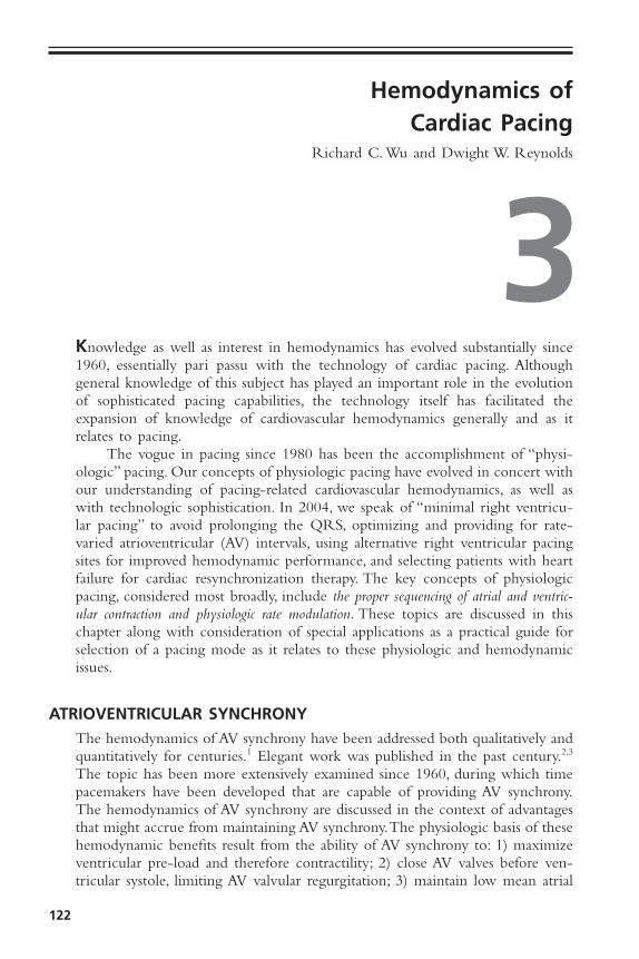
122
Knowledge as well as interest in hemodynamics has evolved substantially since1960, essentially pari passu with the technology of cardiac pacing. Althoughgeneral knowledge of this subject has played an important role in the evolutionof sophisticated pacing capabilities, the technology itself has facilitated theexpansion of knowledge of cardiovascular hemodynamics generally and as itrelates to pacing.
The vogue in pacing since 1980 has been the accomplishment of “physi-ologic” pacing. Our concepts of physiologic pacing have evolved in concert withour understanding of pacing-related cardiovascular hemodynamics, as well aswith technologic sophistication. In 2004, we speak of “minimal right ventricu-lar pacing” to avoid prolonging the QRS, optimizing and providing for rate-varied atrioventricular (AV) intervals, using alternative right ventricular pacingsites for improved hemodynamic performance, and selecting patients with heartfailure for cardiac resynchronization therapy. The key concepts of physiologicpacing, considered most broadly, include the proper sequencing of atrial and ventric-ular contraction and physiologic rate modulation. These topics are discussed in thischapter along with consideration of special applications as a practical guide forselection of a pacing mode as it relates to these physiologic and hemodynamicissues.
ATRIOVENTRICULAR SYNCHRONYThe hemodynamics of AV synchrony have been addressed both qualitatively andquantitatively for centuries.1 Elegant work was published in the past century.2,3
The topic has been more extensively examined since 1960, during which timepacemakers have been developed that are capable of providing AV synchrony.The hemodynamics of AV synchrony are discussed in the context of advantagesthat might accrue from maintaining AV synchrony.The physiologic basis of thesehemodynamic benefits result from the ability of AV synchrony to: 1) maximizeventricular pre-load and therefore contractility; 2) close AV valves before ven-tricular systole, limiting AV valvular regurgitation; 3) maintain low mean atrial
3Hemodynamics of
Cardiac PacingRichard C. Wu and Dwight W. Reynolds
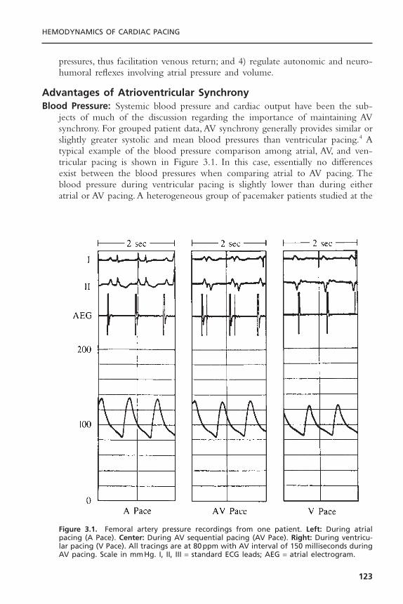
pressures, thus facilitation venous return; and 4) regulate autonomic and neuro-humoral reflexes involving atrial pressure and volume.
Advantages of Atrioventricular SynchronyBlood Pressure: Systemic blood pressure and cardiac output have been the sub-
jects of much of the discussion regarding the importance of maintaining AVsynchrony. For grouped patient data, AV synchrony generally provides similar orslightly greater systolic and mean blood pressures than ventricular pacing.4 Atypical example of the blood pressure comparison among atrial, AV, and ven-tricular pacing is shown in Figure 3.1. In this case, essentially no differencesexist between the blood pressures when comparing atrial to AV pacing. Theblood pressure during ventricular pacing is slightly lower than during eitheratrial or AV pacing. A heterogeneous group of pacemaker patients studied at the
HEMODYNAMICS OF CARDIAC PACING
123
Figure 3.1. Femoral artery pressure recordings from one patient. Left: During atrialpacing (A Pace). Center: During AV sequential pacing (AV Pace). Right: During ventricu-lar pacing (V Pace). All tracings are at 80ppm with AV interval of 150 milliseconds duringAV pacing. Scale in mmHg. I, II, III = standard ECG leads; AEG = atrial electrogram.

University of Oklahoma4 showed statistically significant differences in theirfemoral artery systolic pressure (Fig. 3.2) but not in their diastolic and meanpressures (Table 3.1). The measurements in this study were performed withsupine patients, which may have masked potentially more dramatic differencesif evaluations had been done with the patients in an upright posture.
It has, however, been observed that some individuals have marked decreasesin blood pressure when ventricular pacing is instituted.5,6 Although this is notthe typical response to ventricular pacing, some individuals do have dramaticand symptomatic decreases in systemic blood pressure (Fig. 3.3). Several mech-anisms may be responsible for this phenomenon. Loss of left ventricular preloadvolume from mistimed atrial contraction (loss of atrial “kick”) and loss ofinhibitory cardiac reflexes (due also to inappropriately timed atrial contraction)
CARDIAC PACING AND ICDS
124
Figure 3.2. A comparison of femoral artery systolic pressures in a group of 23 pacemakerpatients. Left: During AV sequential pacing. Right: During ventricular pacing. Both are at80ppm with AV interval during AV pacing equal to 150 milliseconds. Individual compar-isons are inside and connected by solid lines. Group comparison ±SEM is outside. Pairedt tests were used for statistical comparison.
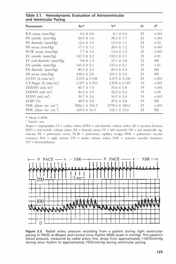
125
Table 3.1. Hemodynamic Evaluation of Atrioventricular and Ventricular Pacing
Parameter Av* V* N P†
RA mean (mmHg) 6.0 ± 0.6 8.1 ± 0.6 22 <.001PA systolic (mmHg) 24.5 ± 1.6 28.3 ± 1.7 23 <.001PA diastolic (mmHg) 12.6 ± 1.0 14.3 ± 1.1 23 <.02PA mean (mmHg) 17.1 ± 1.1 20.6 ± 1.2 23 <.001PCW mean (mmHg) 7.7 ± 1.0 13.4 ± 1.2 22 <.001LV systolic (mmHg) 141.3 ± 5.2 132.0 ± 5.1 23 <.01LV end-diastolic (mmHg) 9.8 ± 1.4 10.1 ± 0.8 22 NSFA systolic (mmHg) 141.4 ± 5.1 133.4 ± 5.1 23 <.01FA diastolic (mmHg) 80.3 ± 2.0 80.9 ± 2.4 23 NSFA mean (mmHg) 105.6 ± 2.8 103.1 ± 3.4 23 NSCI.TD (L/min/m2) 2.575 ± 0.148 2.073 ± 0.126 23 <.001CT.Angio (L/min/m2) 3.337 ± 0.210 2.878 ± 0.157 19 <.001LV.EDVI (mL/m2) 85.7 ± 7.4 76.6 ± 6.8 19 <.001LV.ESVI (mL/m2) 46.2 ± 5.9 42.2 ± 5.4 19 <.05LV.SVI (mL/m2) 39.7 ± 2.6 34.3 ± 2.0 19 <.001LV.EF (%) 48.9 ± 2.8 47.6 ± 2.8 19 NSSVR (dyne · sec · cm-5) 1856.1 ± 160.3 2178.0 ± 180.6 23 <.001PVR (dyne · sec · cm-5) 169.0 ± 16.3 152.1 ± 15.0 22 NS
* Mean ± SEM.† Paired t test.Angio = angiography; CI = cardiac index; EDVI = end-diastolic volume index; EF = ejection fraction;ESVI = end-systolic volume index; FA = femoral artery; LV = left ventricle; NS = not statistically sig-nificant; PA = pulmonary artery; PCW = pulmonary capillary wedge; PVR = pulmonary vascular resistance; RA = right atrium; SVI = stroke volume index; SVR = systemic vascular resistance;TD = thermodilution.
Figure 3.3. Radial artery pressure recording from a patient during right ventricularpacing (V PACE) at 80ppm and normal sinus rhythm (NSR) (scale in mmHg). This patient’sblood pressure, measured by radial artery line, drops from approximately 110/70mmHgduring sinus rhythm to approximately 75/55mmHg during ventricular pacing.

have been the mechanisms most commonly implicated. This marked hypoten-sion can produce dramatic symptoms, including syncope. In a clinical setting, ifthis problem is suspected but hypotension with symptoms cannot be reproducedin a supine position, an upright or semiupright posture may unmask theproblem, especially if it is related to a left ventricular preload deficiency causedby loss of atrial contribution to ventricular filling. An important considerationin the hemodynamic response to ventricular pacing is ventriculoatrial (VA) con-duction. VA conduction, the ability to conduct electrical impulses retrogradefrom the ventricles through the AV junction to the atria, can lead to atrial con-traction during ventricular systole or in cases of long VA conduction, early dias-tole. This can cause loss of the atrial contribution to ventricular filling as wellas other hemodynamic problems, as discussed below. VA conduction has beenfound in as many as 90% of patients with sick sinus syndrome and in 15% to35% of individuals with a variety of degrees of AV block.7–9 This has been amajor issue in the use of hysteresis, a feature commonly included in ventricu-lar pacemakers since 1980.10 During ventricular pacing, even when VA con-duction is not intact, if the ventricular pacing rate is unequal to the atrial rate,there will be periods of time when atrial contraction occurs during ventricu-lar systole with the resulting disadvantageous hemodynamics.
Cardiac Output: Cardiac output, more than any other hemodynamic feature, hasbeen the focus of discussions and investigations relating to AV synchrony.11–13
Properly timed atrial contraction provides a significant increase in ventricularend-diastolic volume and is responsible for the so-called atrial kick. Studies haveshown a wide range in the actual importance of the atrial contribution to ven-tricular filling depending on the patient populations and study conditions. Byincreasing the end-diastolic volumes (right and left ventricles), the cardiac outputis, in turn, increased. The average increase in cardiac output in a broad-basedpacing population, if AV synchrony is maintained, appears to be between 15%and 25% in comparison to non–AV-synchronized ventricular pacing.
In the Oklahoma study, the benefits of AV synchrony were confirmed ina broad-based pacing population (Fig. 3.4; see Table 3.1). AV pacing at 80 pulsesper minute (ppm) with an AV interval of 150 milliseconds was compared withventricular pacing at 80ppm during which VA conduction was intact or wascreated by VA pacing. Consistently higher cardiac outputs maintained by AVsynchrony were seen in both thermodilution and angiographic evaluations.Again, the patients were supine when examined; an upright posture might haveamplified these differences, because in that position ventricular diastolic fillingdepends more on atrial kick due to loss of venous return of blood to the heart(lower extremity pooling).14
The hemodynamic benefits of AV-synchronized versus ventricular pacinghave also been demonstrated for patients after myocardial infarction15 and cardiacsurgery.16,17 Patients with reduced cardiac output—especially if such reducedfunction is due to relative volume depletion or only mild to moderatelydepressed left ventricular function—frequently benefit significantly from main-
CARDIAC PACING AND ICDS
126
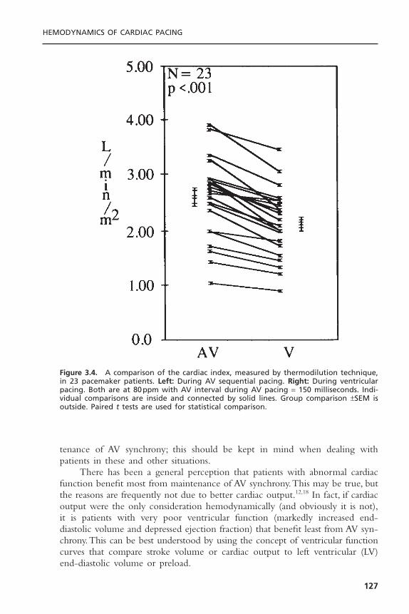
tenance of AV synchrony; this should be kept in mind when dealing withpatients in these and other situations.
There has been a general perception that patients with abnormal cardiacfunction benefit most from maintenance of AV synchrony.This may be true, butthe reasons are frequently not due to better cardiac output.12,18 In fact, if cardiacoutput were the only consideration hemodynamically (and obviously it is not),it is patients with very poor ventricular function (markedly increased end-diastolic volume and depressed ejection fraction) that benefit least from AV syn-chrony.This can be best understood by using the concept of ventricular functioncurves that compare stroke volume or cardiac output to left ventricular (LV)end-diastolic volume or preload.
HEMODYNAMICS OF CARDIAC PACING
127
Figure 3.4. A comparison of the cardiac index, measured by thermodilution technique,in 23 pacemaker patients. Left: During AV sequential pacing. Right: During ventricularpacing. Both are at 80ppm with AV interval during AV pacing = 150 milliseconds. Indi-vidual comparisons are inside and connected by solid lines. Group comparison ±SEM isoutside. Paired t tests are used for statistical comparison.

Figure 3.5 shows hypothetical ventricular function curves for a patient withnormal ventricular function (curve 1), one with moderate LV dysfunction (curve2), one with very poor LV function and a markedly dilated ventricle (curve 3),and a patient with hypertrophic cardiomyopathy (curve 4).These curves describethe performance of the left ventricle in generating stroke volume (or cardiacoutput) in relationship to the end-diastolic volume (or preload). In patients withnormal LV function (curve 1), as end-diastolic volume increases, stroke volume(and cardiac output) increases until the flat or descending portion of the curveis reached. In patients with depressed LV function (curves 2 and 3) there is alesser increase in stroke volume that depends on end-diastolic volume to thepoint that in patients with poor LV function (curve 3) there is negligibleimprovement in stroke volume with further increases in end-diastolic volume.On the other hand, patients with hypertrophic cardiomyopathies tend to havesmall ventricles that are normal (i.e., normal systolic function) or hyperdynamicin function (curve 4). Small increases in end-diastolic volume can significantlyincrease stroke volume in this situation. As has been discussed, AV synchronyprovides the atrial kick that increases end-diastolic volume. Point A on thesecurves represents the hypothetical stroke volume and end-diastolic volumeduring AV pacing. Point B represents stroke volume and end-diastolic volumeduring ventricular pacing (with associated loss of atrial kick). In the normal sit-uation (curve 1), although end-diastolic volume is greater and hence strokevolume is greater during AV-synchronized pacing, the loss of AV synchronyduring ventricular pacing does not drop the end-diastolic volume and the strokevolume significantly.This, however, might not be the case if filling volume wereotherwise reduced by volume depletion due to blood loss, diuresis, and so on.In these situations, even with normal LV function, the higher end-diastolicvolumes and stroke volumes provided by properly timed atrial contraction might
CARDIAC PACING AND ICDS
128
Figure 3.5. Hypothetical ventricular function curves comparing (1) stroke volume (SV)and left ventricular end-diastolic volume (EDV) in patients with normal ventricular func-tion; (2) moderately depressed ventricular function; (3) severely depressed ventricularfunction; and (4) hyperdynamic ventricular function. Point A = with normal AV sequence;and Point B = without normal AV sequence.
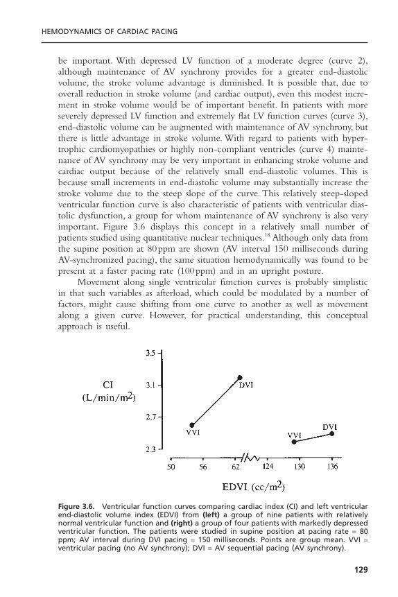
be important. With depressed LV function of a moderate degree (curve 2),although maintenance of AV synchrony provides for a greater end-diastolicvolume, the stroke volume advantage is diminished. It is possible that, due tooverall reduction in stroke volume (and cardiac output), even this modest incre-ment in stroke volume would be of important benefit. In patients with moreseverely depressed LV function and extremely flat LV function curves (curve 3),end-diastolic volume can be augmented with maintenance of AV synchrony, butthere is little advantage in stroke volume. With regard to patients with hyper-trophic cardiomyopathies or highly non-compliant ventricles (curve 4) mainte-nance of AV synchrony may be very important in enhancing stroke volume andcardiac output because of the relatively small end-diastolic volumes. This isbecause small increments in end-diastolic volume may substantially increase thestroke volume due to the steep slope of the curve. This relatively steep-slopedventricular function curve is also characteristic of patients with ventricular dias-tolic dysfunction, a group for whom maintenance of AV synchrony is also veryimportant. Figure 3.6 displays this concept in a relatively small number ofpatients studied using quantitative nuclear techniques.18 Although only data fromthe supine position at 80ppm are shown (AV interval 150 milliseconds duringAV-synchronized pacing), the same situation hemodynamically was found to bepresent at a faster pacing rate (100ppm) and in an upright posture.
Movement along single ventricular function curves is probably simplisticin that such variables as afterload, which could be modulated by a number offactors, might cause shifting from one curve to another as well as movementalong a given curve. However, for practical understanding, this conceptualapproach is useful.
HEMODYNAMICS OF CARDIAC PACING
129
Figure 3.6. Ventricular function curves comparing cardiac index (CI) and left ventricularend-diastolic volume index (EDVI) from (left) a group of nine patients with relativelynormal ventricular function and (right) a group of four patients with markedly depressedventricular function. The patients were studied in supine position at pacing rate = 80ppm; AV interval during DVI pacing = 150 milliseconds. Points are group mean. VVI =ventricular pacing (no AV synchrony); DVI = AV sequential pacing (AV synchrony).
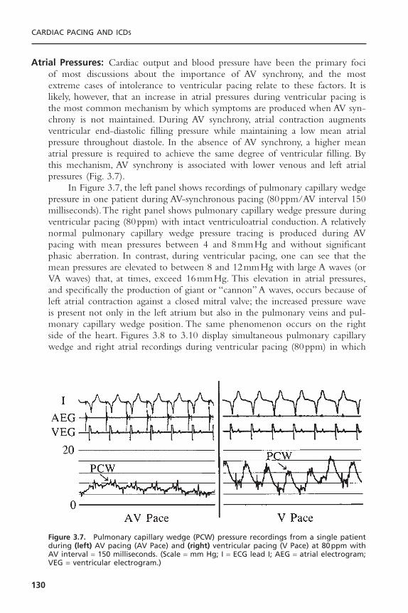
Atrial Pressures: Cardiac output and blood pressure have been the primary fociof most discussions about the importance of AV synchrony, and the mostextreme cases of intolerance to ventricular pacing relate to these factors. It islikely, however, that an increase in atrial pressures during ventricular pacing isthe most common mechanism by which symptoms are produced when AV syn-chrony is not maintained. During AV synchrony, atrial contraction augmentsventricular end-diastolic filling pressure while maintaining a low mean atrialpressure throughout diastole. In the absence of AV synchrony, a higher meanatrial pressure is required to achieve the same degree of ventricular filling. Bythis mechanism, AV synchrony is associated with lower venous and left atrialpressures (Fig. 3.7).
In Figure 3.7, the left panel shows recordings of pulmonary capillary wedgepressure in one patient during AV-synchronous pacing (80ppm/AV interval 150milliseconds).The right panel shows pulmonary capillary wedge pressure duringventricular pacing (80ppm) with intact ventriculoatrial conduction. A relativelynormal pulmonary capillary wedge pressure tracing is produced during AVpacing with mean pressures between 4 and 8mmHg and without significantphasic aberration. In contrast, during ventricular pacing, one can see that themean pressures are elevated to between 8 and 12mmHg with large A waves (orVA waves) that, at times, exceed 16mmHg. This elevation in atrial pressures,and specifically the production of giant or “cannon” A waves, occurs because ofleft atrial contraction against a closed mitral valve; the increased pressure waveis present not only in the left atrium but also in the pulmonary veins and pul-monary capillary wedge position. The same phenomenon occurs on the rightside of the heart. Figures 3.8 to 3.10 display simultaneous pulmonary capillarywedge and right atrial recordings during ventricular pacing (80ppm) in which
CARDIAC PACING AND ICDS
130
Figure 3.7. Pulmonary capillary wedge (PCW) pressure recordings from a single patientduring (left) AV pacing (AV Pace) and (right) ventricular pacing (V Pace) at 80ppm withAV interval = 150 milliseconds. (Scale = mm Hg; I = ECG lead I; AEG = atrial electrogram;VEG = ventricular electrogram.)
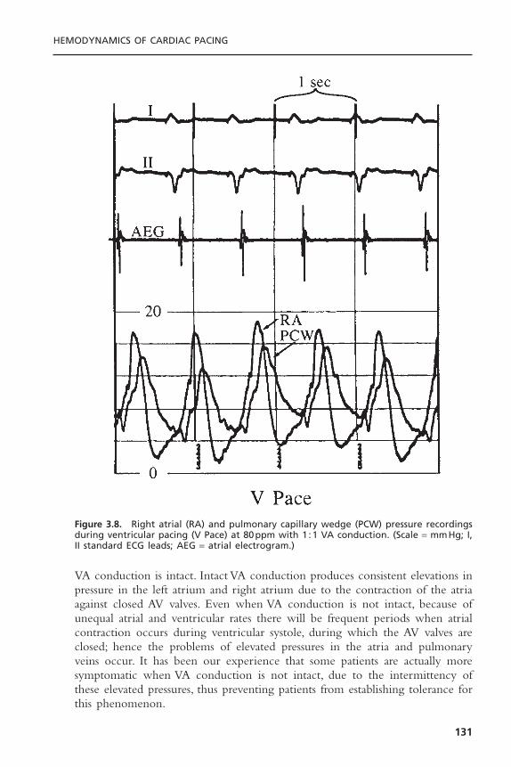
VA conduction is intact. Intact VA conduction produces consistent elevations inpressure in the left atrium and right atrium due to the contraction of the atriaagainst closed AV valves. Even when VA conduction is not intact, because ofunequal atrial and ventricular rates there will be frequent periods when atrialcontraction occurs during ventricular systole, during which the AV valves areclosed; hence the problems of elevated pressures in the atria and pulmonaryveins occur. It has been our experience that some patients are actually moresymptomatic when VA conduction is not intact, due to the intermittency ofthese elevated pressures, thus preventing patients from establishing tolerance forthis phenomenon.
HEMODYNAMICS OF CARDIAC PACING
131
Figure 3.8. Right atrial (RA) and pulmonary capillary wedge (PCW) pressure recordingsduring ventricular pacing (V Pace) at 80ppm with 1 :1 VA conduction. (Scale = mmHg; I,II standard ECG leads; AEG = atrial electrogram.)

The relationship of the phasic changes in the pulmonary capillary wedge(and left atrial) pressures to LV pressures can be seen in Figures 3.11, 3.12, and3.13. Figure 3.11 is a display of normal LV and pulmonary capillary wedge pres-sure recordings during AV pacing (80ppm/AV interval of 150 milliseconds).Theappropriately timed A wave can be seen in both the LV and pulmonary capil-lary wedge pressure recordings. In contrast, as Figure 3.12 shows, during ven-tricular pacing (80ppm) with a consistent 1 :1 VA relationship, the loss of theA wave contribution to the upstroke of the LV pressure recording and the giantA wave, late in ventricular systole, can be seen consistently in the pulmonary
CARDIAC PACING AND ICDS
132
Figure 3.9. Right atrial (RA) and pulmonary capillary wedge (PCW) pressure recordingsduring ventricular pacing (V Pace) at 80ppm with 2 :1 VA conduction. Scale = mmHg; I,II standard ECG leads; AEG = atrial electrogram.
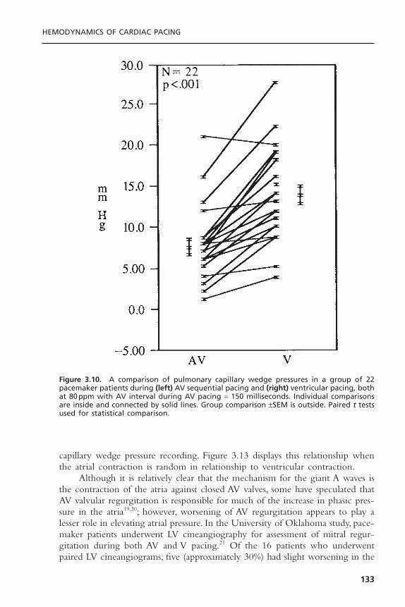
capillary wedge pressure recording. Figure 3.13 displays this relationship whenthe atrial contraction is random in relationship to ventricular contraction.
Although it is relatively clear that the mechanism for the giant A waves isthe contraction of the atria against closed AV valves, some have speculated thatAV valvular regurgitation is responsible for much of the increase in phasic pres-sure in the atria19,20; however, worsening of AV regurgitation appears to play alesser role in elevating atrial pressure. In the University of Oklahoma study, pace-maker patients underwent LV cineangiography for assessment of mitral regur-gitation during both AV and V pacing.21 Of the 16 patients who underwentpaired LV cineangiograms, five (approximately 30%) had slight worsening in the
HEMODYNAMICS OF CARDIAC PACING
133
Figure 3.10. A comparison of pulmonary capillary wedge pressures in a group of 22pacemaker patients during (left) AV sequential pacing and (right) ventricular pacing, bothat 80ppm with AV interval during AV pacing = 150 milliseconds. Individual comparisonsare inside and connected by solid lines. Group comparison ±SEM is outside. Paired t testsused for statistical comparison.
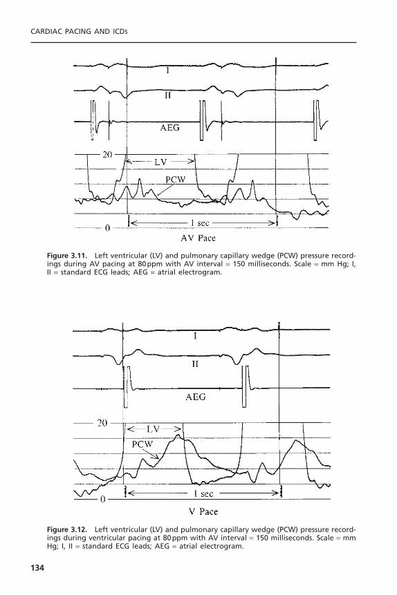
CARDIAC PACING AND ICDS
134
Figure 3.11. Left ventricular (LV) and pulmonary capillary wedge (PCW) pressure record-ings during AV pacing at 80ppm with AV interval = 150 milliseconds. Scale = mm Hg; I,II = standard ECG leads; AEG = atrial electrogram.
Figure 3.12. Left ventricular (LV) and pulmonary capillary wedge (PCW) pressure record-ings during ventricular pacing at 80ppm with AV interval = 150 milliseconds. Scale = mmHg; I, II = standard ECG leads; AEG = atrial electrogram.
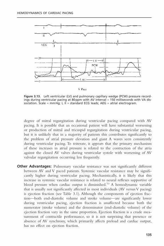
degree of mitral regurgitation during ventricular pacing compared with AVpacing. It is possible that an occasional patient will have substantial worseningor production of mitral and tricuspid regurgitation during ventricular pacing,but it is unlikely that in a majority of patients this contributes significantly tothe problem of atrial pressure elevation and giant A waves seen consistentlyduring ventricular pacing. To reiterate, it appears that the primary mechanismof these increases in atrial pressure is related to the contraction of the atriaagainst the closed AV valves during ventricular systole with worsening of AVvalvular regurgitation occurring less frequently.
Other Advantages: Pulmonary vascular resistance was not significantly differentbetween AV and V paced patients. Systemic vascular resistance may be signifi-cantly higher during ventricular pacing. Mechanistically, it is likely that thisincrease in systemic vascular resistance is related to neural reflexes supportive ofblood pressure when cardiac output is diminished.5,6 A hemodynamic variablethat is usually not significantly affected in most individuals (AV versus V pacing)is ejection fraction (see Table 3.1). Although the components of ejection frac-tion—both end-diastolic volume and stroke volume—are significantly lowerduring ventricular pacing, ejection fraction is unaffected because both thenumerator (stroke volume) and the denominator (end-diastolic volume) of theejection fraction vary in the same proportion. Ejection fraction is a crude mea-surement of contractile performance, so it is not surprising that presence orabsence of AV synchrony, which primarily affects preload and cardiac output,has no effect on ejection fraction.
HEMODYNAMICS OF CARDIAC PACING
135
Figure 3.13. Left ventricular (LV) and pulmonary capillary wedge (PCW) pressure record-ings during ventricular pacing at 80ppm with AV interval = 150 milliseconds with VA dis-sociation. Scale = mmHg; I, II = standard ECG leads; AEG = atrial electrogram.

It appears that pacing modalities have little effect on most hormonal levels,but atrial natriuretic peptide (ANP), an atrially produced hormone, does appearto be increased during ventricular pacing. This increase is probably related torelease of the hormone in response to the stress of higher atrial pressures.22 Theimportance of the increase is unclear.Ventricular pacing does, however, increaseperipheral sympathetic nerve tone and circulating catecholamine levels.23
While non-randomized studies have reported differences in survivalbetween patients undergoing AV synchronous and ventricular pacing, the resultsof controlled randomized trials have dispelled these findings.24–27 It is nowbelieved that AV synchronous pacing provides no survival benefit over ventric-ular pacing alone.
Effects of Atrioventricular IntervalThe mere presence of a consistent AV relationship does not assure optimalhemodynamics and as described, some relationships are detrimental as with 1:1VA conduction. Similarly, inappropriately short or long AV delays can be detri-mental. An excessively long AV delay may inadequately fill the ventricle bycausing early mitral valve closure and truncating diastolic filling time. In addi-tion, diastolic AV valvular regurgitation may occur with re-opening of the valvebefore ventricular systole. An excessively short AV delay may limit active fillingof the ventricle and promote systolic AV valvular regurgitation as ventricularcontraction begins while the AV valves are still open. It appears that, at rest, 125to 200 milliseconds is generally the optimal range if the right atrium and ven-tricle are paced.28,29 On the other hand, more precise optimization may be pos-sible, although it may vary from patient to patient and from time to time in aspecific patient. In addition, with conventional right heart pacing systems, theactivation sequence of the left-sided chambers may be quite different from theprogrammed values due to marked interatrial and interventricular conductiondelays. Doppler echocardiography is commonly used to optimize the AV inter-val by assessing the pattern of early and late diastolic mitral valve flow and theaortic flow velocity integral (Figs. 3.14 and 3.15).While AV interval can be opti-mized at rest, assessing the adequacy of this parameter upright and during exer-cise presents greater technical difficulties.
There is some predictability in certain aspects of AV interval optimization.It is consistent that optimal hemodynamics at higher heart rates require shorterAV delays than are optimal at lower rates. With exercise, there is a relativelylinear decrease in the normal PR interval as exercise increases from the restingstate to near maximal exertion.30 The total reduction in spontaneous PR inter-val in normal individuals appears to be about 20 to 50 milliseconds or approx-imately 4 milliseconds for each 10-beat increment in heart rate. Sophisticatedpacing systems have already been developed that incorporate this concept. Itappears that cardiac output can be more effectively increased and pulmonarycapillary wedge pressures (and presumably atrial pressures) can be effectivelymaintained at lower levels using rate-variable AV intervals rather than fixed AVintervals.
CARDIAC PACING AND ICDS
136
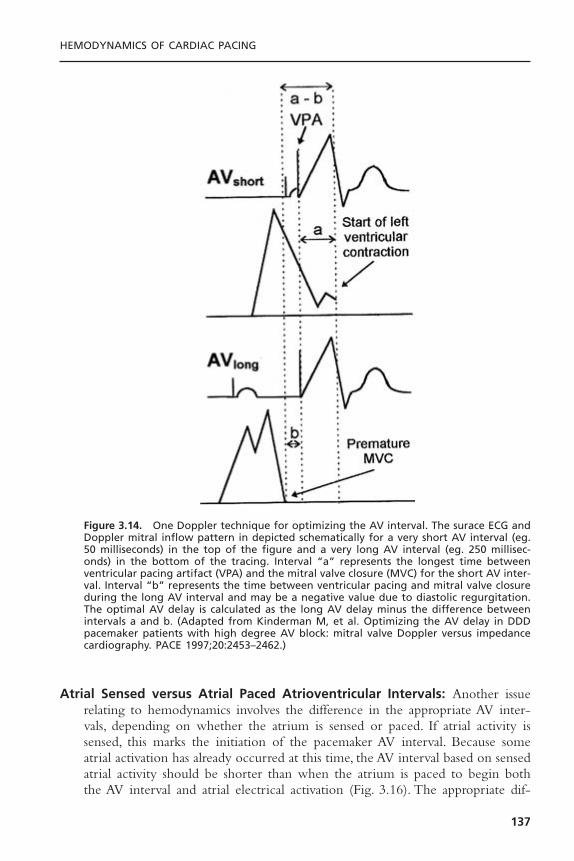
Atrial Sensed versus Atrial Paced Atrioventricular Intervals: Another issuerelating to hemodynamics involves the difference in the appropriate AV inter-vals, depending on whether the atrium is sensed or paced. If atrial activity issensed, this marks the initiation of the pacemaker AV interval. Because someatrial activation has already occurred at this time, the AV interval based on sensedatrial activity should be shorter than when the atrium is paced to begin boththe AV interval and atrial electrical activation (Fig. 3.16). The appropriate dif-
HEMODYNAMICS OF CARDIAC PACING
137
Figure 3.14. One Doppler technique for optimizing the AV interval. The surace ECG andDoppler mitral inflow pattern in depicted schematically for a very short AV interval (eg.50 milliseconds) in the top of the figure and a very long AV interval (eg. 250 millisec-onds) in the bottom of the tracing. Interval “a” represents the longest time betweenventricular pacing artifact (VPA) and the mitral valve closure (MVC) for the short AV inter-val. Interval “b” represents the time between ventricular pacing and mitral valve closureduring the long AV interval and may be a negative value due to diastolic regurgitation.The optimal AV delay is calculated as the long AV delay minus the difference betweenintervals a and b. (Adapted from Kinderman M, et al. Optimizing the AV delay in DDDpacemaker patients with high degree AV block: mitral valve Doppler versus impedancecardiography. PACE 1997;20:2453–2462.)
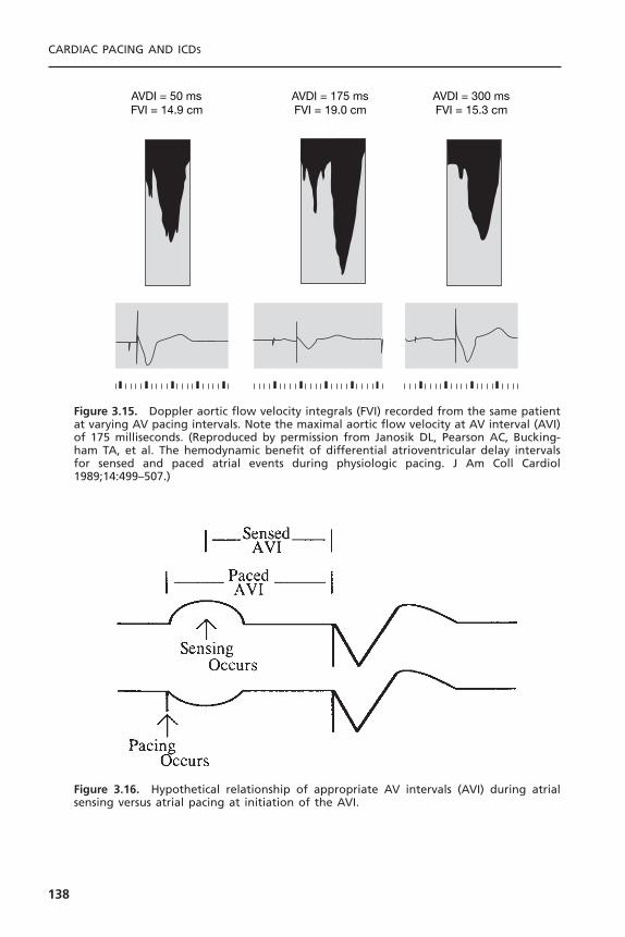
CARDIAC PACING AND ICDS
138
AVDI = 50 msFVI = 14.9 cm
AVDI = 175 msFVI = 19.0 cm
AVDI = 300 msFVI = 15.3 cm
Figure 3.15. Doppler aortic flow velocity integrals (FVI) recorded from the same patientat varying AV pacing intervals. Note the maximal aortic flow velocity at AV interval (AVI)of 175 milliseconds. (Reproduced by permission from Janosik DL, Pearson AC, Bucking-ham TA, et al. The hemodynamic benefit of differential atrioventricular delay intervalsfor sensed and paced atrial events during physiologic pacing. J Am Coll Cardiol1989;14:499–507.)
Figure 3.16. Hypothetical relationship of appropriate AV intervals (AVI) during atrialsensing versus atrial pacing at initiation of the AVI.

ference in the atrial sensed AV interval setting and the atrial paced AV intervalsetting is probably variable in different patients; the most appropriate values forthese parameters are somewhat empirically determined.31 Generally, an atrialsensed AV interval 20 to 50 milliseconds less than the atrial paced AV intervalhas been used at our institution.
Atrial versus Atrioventricular PacingBoth atrial and AV pacing have the advantage of providing AV synchrony. Thechoice of atrial versus AV pacing is usually made on the basis of considerationsother than hemodynamics. We compared the hemodynamics of atrial and AVpacing in a group of pacemaker patients who were not selected for hemody-namic status.32 The results of the comparison are shown in Table 3.2.The pacingrate in this study was 80ppm, and the AV interval during AV pacing was 150milliseconds. The study was done with patients in the supine position. Exceptfor pulmonary artery and pulmonary capillary wedge pressures, there were nostatistically significant differences found when comparing atrial to AV pacing.For example, the cardiac index for the group as a whole showed no significantdifference between atrial and AV pacing, although small differences were seenin some patients. It is likely that the small but statistically significant differencesin pulmonary artery and pulmonary capillary wedge pressures are related to asuboptimal AV interval during AV pacing. Other studies have shown improvedcardiac output, ejection fraction and pulmonary capillary wedge pressure withAAI compared to DDD pacing.33,34
HEMODYNAMICS OF CARDIAC PACING
139
Table 3.2. Hemodynamic Evaluation of Atrial and Atrioventricular Pacing
Parameter A* Av* N P†
RA mean (mmHg) 5.8 ± 0.7 6.7 ± 0.6 19 NSPA systolic (mmHg) 24.1 ± 1.5 25.4 ± 1.7 20 .05PA diastolic (mmHg) 12.1 ± 0.9 13.4 ± 1.0 20 .01PA mean (mmHg) 16.5 ± 1.0 18.0 ± 1.2 20 .02PCW mean (mmHg) 6.7 ± 0.9 8.3 ± 1.0 20 .01LV systolic (mmHg) 143.8 ± 7.1 145.7 ± 7.2 20 NSLV end-diastolic (mmHg) 8.8 ± 0.9 10.7 ± 1.4 20 NSAO systolic (mmHg) 145.0 ± 7.0 146.2 ± 7.1 20 NSAO diastolic (mmHg) 81.8 ± 2.0 82.1 ± 2.4 20 NSAO mean (mmHg) 107.2 ± 3.2 108.1 ± 3.5 20 NSCI (L/min/m2) 2.66 ± 0.15 2.62 ± 0.15 20 NSPVR (dyne · sec · cm-5) 168 ± 17 174 ± 20 20 NSSVR (dyne · sec · cm-5) 1769 ± 148 1816 ± 166 20 NS
* Mean ± SEM.† Paired t test.AO = aortic; CI = cardiac index; LV = left ventricle; NS = not statistically significant; PA = pulmonaryartery; PCW = pulmonary capillary wedge; PVR = pulmonary vascular resistance; RA = right atrium;SVR = systemic vascular resistance.
Besides differing AV intervals, another difference between atrial and AVsequential pacing is the ectopic ventricular activation with the dual-chambermode. In detailed human studies, ventricular pacing compared to intrinsic ven-tricular activation can produce measurable increases in left ventricular fillingpressures and end-systolic volume as well as reductions in regional septal ejec-tion fraction, ventricular dP/dt, stroke volume, and indices of diastolic function.34
As a result there is growing concern over the long-term consequences of rightventricular pacing and pacemaker algorithms that allow for maintenance of AVsynchrony and minimize unnecessary ventricular pacing evolving.
Pacemaker SyndromePacemaker syndrome is a term proposed in 1974 to describe a condition com-prising a variety of symptoms and signs produced by ventricular pacing.23,35,36
Pacemaker syndrome has been defined differently by different investigators, butthe broadest definition is probably most appropriate. It is best thought of as anycombination of the variety of symptoms and signs occurring with ventricularpacing that are relieved by restoration of AV synchrony.Although it is most oftenthe result of VVI pacing, pacemaker syndrome can result from any pacing modethat results in AV dyssynchrony, even AAI pacing with long PR intervals.
Two difficulties in ascribing symptoms and signs specifically to pacemakersyndrome are commonly encountered. First, patients who have pacemakersimplanted are frequently patients with other cardiovascular problems thatproduce the symptoms and signs described. Second, unfortunately, many pace-maker patients have the belief that having the pacemaker, de facto, forces themto accept a less than normal sense of well-being. An extreme symptom fre-quently associated with pacemaker syndrome is syncope. Syncope is veryuncommon and is most likely related to profound hypotension—and, in some,a decrease in cardiac output—associated with loss of AV synchrony. Additionalsymptoms related to blood pressure and cardiac output include malaise, easy fati-gability, a sense of weakness, lightheadedness, and dizziness. Symptoms related tohigher atrial and venous pressures include dyspnea (frequently at rest), orthop-nea, paroxysmal nocturnal dyspnea, a sensation of fullness and/or pulsations inthe neck and chest, as well as palpitations, chest pain, nausea, and peripheraledema. Experience has shown that careful questioning is frequently necessary toelucidate these symptoms. It is not uncommon for patients who have had apacemaker implanted for some time to deny symptoms, but on specific ques-tioning, to admit to having experienced symptoms that can be directly relatedto ventricular pacing with loss of AV synchrony.
Careful examination is necessary to find physical signs related to ventric-ular pacing. Some of these signs include relative or absolute hypotension thatcan be continuous or fluctuating, neck vein distension with prominent “cannon”A waves, pulmonary rales, and rarely peripheral edema.
Pacemaker syndrome is most severe when intact retrograde VA conductionis present. Besides the reduced stroke volume and cardiac output from the lossof atrial kick, the elevated venous pressures resulting from atrial contraction
CARDIAC PACING AND ICDS
140

against closed AV valves activate atrial and pulmonary vagal afferent nerves.Thisin turn produces peripheral vasodilation and hypotension. Patients with pace-maker syndrome have a failure to increase systemic vascular resistance inresponse to VVI pacing despite elevated peripheral sympathetic nerve traffic andcirculating catecholamines. These findings suggest offsetting parasympatheticactivation or failure of end-organ responsiveness.
Pacemaker syndrome can often be prevented by simple hemodynamic eval-uation at the time of pacer implant. Pacemaker syndrome is likely to result fromVVI pacing if the blood pressure drops by more than 20mmHg during ven-tricular pacing. Retrograde conduction is not uncommon even in patients withcomplete heart block. If hypotension develops, implantation of a dual-chamberpacing system is requisite. Because retrograde conduction may be intermittent,absence of hypotension at implant does not preclude pacemaker syndrome.Themanagement of patients with VVI-pacemaker syndrome after VVI-pacemakerimplantation include upgrading to a DDD system, reducing the lower pacingrate to encourage conduction of sinus rhythm, use of hysteresis, or withdrawalof medications that impair sinus node function. For the rare patients with pace-maker syndrome and dual-chamber systems, programming to ensure atrialcapture, avoidance of atrial non-pacing modes (VDD) or atrial non-trackingmodes (DDI or DVI) may be useful. Fortunately, in the United States, there hasbeen a dramatic reduction in the use of VVI/VVIR pacing of the past 20 yearsand this has in turn dramatically reduced the prevalence of pacemaker syndrome.
Hemodynamics of Alternative Site Right Ventricular PacingPacing from the right ventricular outflow tract (RVOT) offers the theoreticaladvantages of a more normal electrocardiographic vector of ventricular activa-tion due to basilar to apical conduction and earlier activation of the bundle ofHis. One study has demonstrated the feasibility of permanent para-Hisian pacingto produce a narrow paced QRS complex identical to that in sinus rhythm.37
Despite these theoretical advantages, the clinical benefits of RVOT pacing havebeen difficult to demonstrate. Some studies have found significant acute hemo-dynamic advantages; however, several randomized controlled chronic studies havedemonstrated either modest or negligible benefit to RVOT or multisite rightventricular pacing compared to right ventricular apical (RVA) pacing.38–42 Thesestudies did not fully examine the role of patient selection for such factors aspresence of atrial fibrillation, type and degree of heart failure, interventricularconduction delay, degree of mitral regurgitation and diastolic dysfunction, whichmay influence the response to pacing.
A large, multicenter, prospective, randomized cross-over trial was designedto examine differences between single site RVA pacing and alternative siteRVOT pacing, as well as dual-site (RVA and RVOT) pacing. In the Right Ven-tricular Outflow Versus Apical Pacing (ROVA) study, all patients (103 enrolled)had indications for VVIR pacing, a history of heart failure (NYHA class II orIII), LV dysfunction (LV ejection fraction [LVEF] £ 40%), and chronic atrial fib-rillation (AF > 7 days).43 The primary endpoint was health-related quality of
HEMODYNAMICS OF CARDIAC PACING
141

life after 3 months. Secondary endpoints were NYHA functional class, LVEF,severity of mitral regurgitation by echocardiography, exercise capacity, and lead-related complications. At 3 months follow-up, the main finding was that no sig-nificant benefit was observed in RVOT or dual-site RV pacing compared toRVA pacing.Although QRS duration significantly shortened during RVOT (149± 19 milliseconds) and dual-site RV pacing (164 ± 18 milliseconds, respectively)compared with RVA pacing (180 ± 23 milliseconds), surprisingly, at 9 monthsof follow-up, LVEF was higher in those assigned to RVA pacing (47.3 ± 17.6%)than during RVOT pacing (34.3 ± 13.4%).
Right ventricular septal (RVS) pacing has also been examined in small clin-ical studies. Several studies have suggested acute hemodynamic benefits duringRVS pacing in patients with reduced left ventricular function, presumably dueto a shorter activation time between the septum and left ventricle (shorter QRS)during RVS pacing compared to other right ventricular sites.38–40 However, long-term clinical benefit has not been demonstrated.40,43,44 One study (14 patients)tested whether RVS pacing functionally correlated with a shorter QRS dura-tion and higher ejection fraction when compared to RVA pacing.45 The QRSduration was generally shorter with RVS pacing in most patients (64%), butsometimes longer (29%) or unchanged compared to RVA pacing. Overall, theQRS duration was not significantly different between RVS and RVA pacing(156 ± 10 milliseconds vs 166 ± 18 milliseconds, respectively).The study foundthat a shorter QRS duration positively correlated with a higher left ventricularejection fraction, but that RVS pacing site did not necessarily produce the short-est QRS or consistently result in improved left ventricular function.
Detrimental Effects of Continuous Right Ventricular PacingContinuous right ventricular pacing may have detrimental effects on myocar-dial function and result in progression of heart failure in patients with left ven-tricular dysfunction. Right ventricular pacing produces an asynchronous patternof activation, contraction, and relaxation between the left and right ventri-cles.41,46,47 Experimental studies have shown that chronic right ventricular pacinginduces abnormal histologic changes, left ventricular hypertrophy or thinning,and subsequent impairment of left ventricular function.41 In patients with com-plete AV block and normal ventricular function at the time of permanent leadimplantation, chronic right ventricular pacing may induce regional myocardialperfusion defects, wall motion abnormalities, and impaired left ventricular sys-tolic and diastolic function.46,47
In a recent study of patients with sinus node dysfunction, continuous rightventricular apical pacing was associated with an increased risk of heart failureand atrial fibrillation, even among patients with preserved AV synchrony andnormal baseline QRS duration.46 The study was a subgroup analysis of patients(n = 1339) enrolled in the MOde Selection Trial (MOST), a large, multicenter,randomized trial comparing single-chamber rate-modulated pacing (VVIR)pacing versus dual-chamber rate-modulated pacing (DDDR).The main findingwas that ventricular desynchronization imposed by RVA pacing in the DDDR
CARDIAC PACING AND ICDS
142

mode greater than 40% of the time conferred a 2.6-fold increased risk of heartfailure hospitalization compared with lesser pacing among similar patients witha normal baseline QRS duration.Ventricular pacing in the VVIR mode greaterthan 80% of the time was also associated with increased heart failure risk. Inabsolute terms, the average risk of heart failure in those receiving RVA pacingwas approximately 10%; however, the risk was approximately 2% if RVA pacingwas minimal (<10% of the time).The risk of atrial fibrillation increased linearlywith cumulative RVA pacing in both groups. The investigators concluded thatboth heart failure progression and atrial fibrillation may be reduced by imple-menting strategies that minimize ventricular pacing and preserve normal ven-tricular activation.
The use of implantable cardioverter defibrillator (ICD) therapy withbackup ventricular pacing has become standard treatment for patients with car-diomyopathies at increased risk for life-threatening ventricular arrhythmia.Because bradycardia (sinus node dysfunction) is also prevalent in the ICD patientpopulation, cardiologists have implanted more dual-chamber devices to treatboth bradyarrhythmias and tachyarrhythmias. Studies also suggest that synchro-nous dual-chamber pacing may improve hemodynamics or suppress arrhyth-mias.48 However, heart failure is a common comorbidity in patients withindications for ICDs. MADIT II, the first ICD clinical trial which includedpatients with dual-chamber ICDs in their study, reported a significant associa-tion between heart failure hospitalization with the presence of an ICD.49 Thestudy implicates continuous right ventricular pacing as a potential risk factor forheart failure progression.
The Dual Chamber and VVI Implantable Defibrillator (DAVID) trial testedthe hypothesis that dual-chamber pacing for rate support would be more effi-cacious than backup pacing in patients receiving ICDs. The trial was a multi-center, randomized, blinded, parallel study of 506 patients with standardindications for ICD implantation (VT/VF, LVEF £ 40%) but without indi-cations for antibradycardia pacing.50 All patients had a dual-chamber, rate-responsive pacing ICD implanted and were randomized to ventricular backuppacing (VVI 40) or dual chamber rate-responsive pacing (DDDR 70, averageAV delay 180 milliseconds). The primary end point was freedom from deathand absence of hospitalization for heart failure. The study was prematurely dis-continued by the data and safety monitoring board because of increased mor-tality and hospitalization for patients treated with dual-chamber pacing (73.3%1-year survival and 22.6% requiring hospitalization) compared to backup pacing(83.9% survival and 13.3% hospitalization).
At the University of Oklahoma, adult patients with a primary indicationfor bradycardia pacing generally undergo right ventricular lead placement at theapex (RVA). Lead placement in the RVA usually offers easier technical posi-tioning, a lower incidence of lead complications, and increased long-term sta-bility (see Chapter on Techniques of Pacemaker Implantation). Additionally, inpatients with ventricular arrhythmias undergoing ICD implant, placement of anintegrated pacing and defibrillation lead at the RVA favorably lowers the defi-
HEMODYNAMICS OF CARDIAC PACING
143
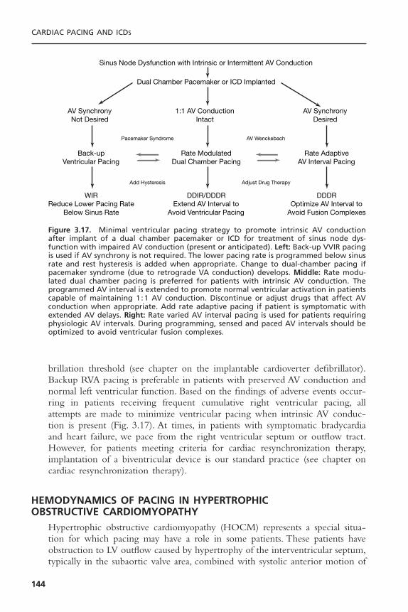
brillation threshold (see chapter on the implantable cardioverter defibrillator).Backup RVA pacing is preferable in patients with preserved AV conduction andnormal left ventricular function. Based on the findings of adverse events occur-ring in patients receiving frequent cumulative right ventricular pacing, allattempts are made to minimize ventricular pacing when intrinsic AV conduc-tion is present (Fig. 3.17). At times, in patients with symptomatic bradycardiaand heart failure, we pace from the right ventricular septum or outflow tract.However, for patients meeting criteria for cardiac resynchronization therapy,implantation of a biventricular device is our standard practice (see chapter oncardiac resynchronization therapy).
HEMODYNAMICS OF PACING IN HYPERTROPHIC OBSTRUCTIVE CARDIOMYOPATHY
Hypertrophic obstructive cardiomyopathy (HOCM) represents a special situa-tion for which pacing may have a role in some patients. These patients haveobstruction to LV outflow caused by hypertrophy of the interventricular septum,typically in the subaortic valve area, combined with systolic anterior motion of
CARDIAC PACING AND ICDS
144
Sinus Node Dysfunction with Intrinsic or Intermittent AV Conduction
Dual Chamber Pacemaker or ICD Implanted
Pacemaker Syndrome AV Wenckebach
Add Hysteresis Adjust Drug Therapy
AV SynchronyNot Desired
1:1 AV ConductionIntact
AV SynchronyDesired
Back-upVentricular Pacing
Rate ModulatedDual Chamber Pacing
Rate AdaptiveAV Interval Pacing
WIRReduce Lower Pacing Rate
Below Sinus Rate
DDIR/DDDRExtend AV Interval to
Avoid Ventricular Pacing
DDDROptimize AV Interval to
Avoid Fusion Complexes
Figure 3.17. Minimal ventricular pacing strategy to promote intrinsic AV conductionafter implant of a dual chamber pacemaker or ICD for treatment of sinus node dys-function with impaired AV conduction (present or anticipated). Left: Back-up VVIR pacingis used if AV synchrony is not required. The lower pacing rate is programmed below sinusrate and rest hysteresis is added when appropriate. Change to dual-chamber pacing ifpacemaker syndrome (due to retrograde VA conduction) develops. Middle: Rate modu-lated dual chamber pacing is preferred for patients with intrinsic AV conduction. Theprogrammed AV interval is extended to promote normal ventricular activation in patientscapable of maintaining 1 :1 AV conduction. Discontinue or adjust drugs that affect AVconduction when appropriate. Add rate adaptive pacing if patient is symptomatic withextended AV delays. Right: Rate varied AV interval pacing is used for patients requiringphysiologic AV intervals. During programming, sensed and paced AV intervals should beoptimized to avoid ventricular fusion complexes.

the mitral valve. A number of studies documented that, by producing dyssyn-chrony of LV contraction, dual-chamber pacing reduces the degree of outflowobstruction and symptoms in many patients.51–54 Objective as well as subjectiveimprovement in such parameters as oxygen consumption at peak exercise hasbeen documented.55 An example of modest improvement in left ventricularoutflow gradient is shown in Figure 3.18.
A full understanding of the mechanisms responsible for improvement islacking, and the possible role of pacing in improving diastolic function and mitralregurgitation is debated. Despite the theoretical and acute hemodynamic effectsof ventricular pacing, the results of controlled, randomized trials of pacing forHOCM have been disappointing. The placebo effect of pacing system implan-tation appears to play an important role in overall subjective improvement.53 Inthese patients, pacing has not been shown to reduce mortality in this conditionand that the long-term benefits from this therapy are less than what were sug-gested by early reports. Data from a recent multicenter review document a veryhigh incidence of sudden cardiac death in this condition.56 Whether AV pacingincorporated into implantable defibrillators will play an important role in thetreatment of these patients in the future must be determined.
Hemodynamics of Left Ventricular PacingAlthough the inefficacy of simple right ventricular pacing for dilated car-diomyopathy has been recognized,51–55 there is growing enthusiasm for biven-tricular pacing therapy in treating patients who have baseline QRS prolongationand severely depressed left ventricular systolic function. A more complete dis-cussion of left ventricular pacing is given in the chapter on cardiac resynchro-nization therapy. This therapy seeks to optimize left ventricular contraction bynormalizing the dysfunctional activation patterns associated with ventricularconduction delays. The biventricular devices pace the right atrium, the rightventricle, and the left ventricle, accessed via the coronary sinus transvenously orfrom the epicardium surgically. There is evidence that, in some patients, pacingthe right atrium and just the left ventricle is hemodynamically beneficial.57 Thestudies to date have primarily focused on patients with severely reduced leftventricular systolic function, refractory heart failure, markedly prolonged QRSdurations (usually due to left bundle branch block), and no bradycardiac indi-cation for pacing.
Numerous acute studies have shown that pacing both ventricles simulta-neously is of hemodynamic benefit in patients with QRS prolongation anddepressed ejection fraction. Much uncertainty remains about the mechanisms bywhich hemodynamic improvement occurs, but several factors are likely.The firstis improvement of atrial/left ventricular synchrony to optimize end-diastolicfilling and reduce diastolic mitral regurgitation.57–59 Second, is a lengthening ofdiastolic filling times due to a shorted QRS duration. The third and probablymost important factor is “resynchronization” of the severely uncoordinated anddysfunctional patterns of ventricular contraction in patients with prolongednative QRS complexes (Fig. 3.19).60,61 With marked intraventricular conduction
HEMODYNAMICS OF CARDIAC PACING
145
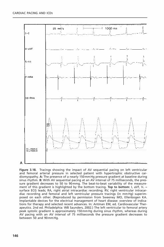
CARDIAC PACING AND ICDS
146
A
Figure 3.18. Tracings showing the impact of AV sequential pacing on left ventricularand femoral arterial pressure in selected patient with hypertrophic obstructive car-diomyopathy. A: The presence of a nearly 150mmHg pressure gradient at baseline duringsinus rhythm. B: With AV sequential pacing at an AV interval of 75 milliseconds, the pres-sure gradient decreases to 50 to 90mmg. The beat-to-beat variability of the measure-ment of this gradient is highlighted by the bottom tracing. Top to bottom: I, aVf, V1 =surface ECG leads; RA, right atrial intracardiac recording; RV, right ventricular intracar-diac recording and femoral and left ventricular pressure tracings (in mmHg) superim-posed on each other. (Reproduced by permission from Sweeney MO, Ellenbogen KA.Implantable devices for the electrical management of heart disease: overview of indica-tions for therapy and selected recent advances. In: Antman EM, ed. Cardiovascular Ther-apeutics. 2nd ed. Philadelphia: WB Saunders, 2002.) The left ventricular to femoral arterypeak systolic gradient is approximately 150mmHg during sinus rhythm, whereas duringAV pacing with an AV interval of 75 milliseconds the pressure gradient decreases tobetween 50 and 90mmHg.

delays, regions of the ventricle may still be actively contracting while otherregions are relaxing and filling in diastole (see Fig. 3.19). The result is that partof the contractile effort does not contribute to cardiac ejection. In addition,interventricular conduction delays may impair the synergy provided by simulta-neous right and left ventricular contraction.
In acute studies, there is improvement in systolic blood pressure, wedgepressure, cardiac output, and reduced V wave amplitude with biventricular pacingcompared to intrinsic conduction or right ventricular pacing.57–61 Several largemulticenter, randomized trials have been completed to definitively evaluate long-
HEMODYNAMICS OF CARDIAC PACING
147
B
Figure 3.18. Continued
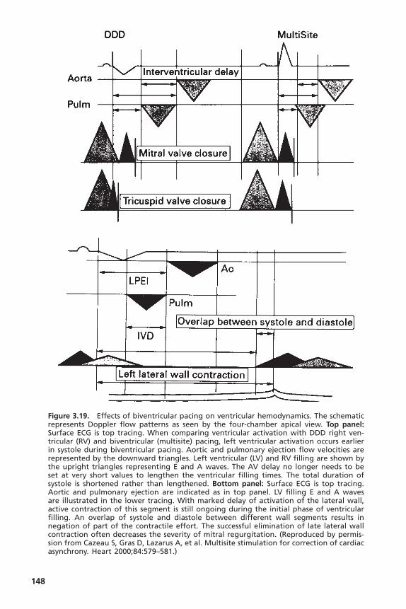
148
Figure 3.19. Effects of biventricular pacing on ventricular hemodynamics. The schematicrepresents Doppler flow patterns as seen by the four-chamber apical view. Top panel:Surface ECG is top tracing. When comparing ventricular activation with DDD right ven-tricular (RV) and biventricular (multisite) pacing, left ventricular activation occurs earlierin systole during biventricular pacing. Aortic and pulmonary ejection flow velocities arerepresented by the downward triangles. Left ventricular (LV) and RV filling are shown bythe upright triangles representing E and A waves. The AV delay no longer needs to beset at very short values to lengthen the ventricular filling times. The total duration ofsystole is shortened rather than lengthened. Bottom panel: Surface ECG is top tracing.Aortic and pulmonary ejection are indicated as in top panel. LV filling E and A wavesare illustrated in the lower tracing. With marked delay of activation of the lateral wall,active contraction of this segment is still ongoing during the initial phase of ventricularfilling. An overlap of systole and diastole between different wall segments results innegation of part of the contractile effort. The successful elimination of late lateral wallcontraction often decreases the severity of mitral regurgitation. (Reproduced by permis-sion from Cazeau S, Gras D, Lazarus A, et al. Multisite stimulation for correction of cardiacasynchrony. Heart 2000;84:579–581.)

term outcomes. These trials are described in the chapter on cardiac resynchro-nization therapy.
Because biventricular pacing avoids the detrimental effects of right ven-tricular pacing alone, the demonstration of long-term benefits from biventric-ular pacing would serve a growing population of patients who have heart failureand potentially a broad scope of patients who have left ventricular dysfunctionand require anti-bradycardia ventricular pacing. Biventricular pacing will likelyexpand in use for patients with chronic atrial fibrillation, particularly those whorequire atrioventricular junction ablation for either heart rate control or treat-ment of symptoms. A small study demonstrated that CRT in patients with con-gestive heart failure and previous AV junction ablation with RV pacing forchronic atrial fibrillation had improvement of symptoms and LV systolic func-tion following upgrade to biventricular pacing.62 Preliminary result for the PostAV Nodal Ablation Evaluation (PAVE) Trial support the use of biventricularpacing. The prospective, randomized study compared biventricular pacing withRV pacing in 252 patients (NYHA class I to III) who underwent AV junctionablation. The exercise capacity (primary endpoint, 6-minute walk test) was significantly better in patients receiving biventricular pacing (mean distance25.55m further) compared to those receiving RV pacing. Functional capacity (peak VO2) and LV ejection fraction (44.9% vs 40.7%) were also greater in thegroup with biventricular pacing, although there was no significant difference in survival.
RATE MODULATIONAs with AV synchrony, terminology here can be confusing. The earliest termused to describe the physiologic property of pacing systems was rate responsive.Significant objection to this term (for grammatical reasons) has led to the moreacceptable use of the terms rate adaptive and rate modulating. All these terms areused to describe the capacity of a pacing system to respond to physiologic needby increasing and decreasing pacing rate. The capability of a pacing systemdepends on the presence of one of a variety of physiologic sensors that monitorneed or indication for rate variability.
The predominant need for rate modulation derives from physical activityor exertion. There are other physiologic situations in which normally there aremodulations of heart rate—for example, with fever and emotional stress.These,however, are substantially less important, especially in the context of pacingsystems.The technology of physiologic sensors is discussed in Chapter 2.A com-prehensive discussion of exercise physiology is beyond the scope of this book,but the more important and relevant concepts will be addressed.
Exercise PhysiologyThe importance of rate modulation in pacing systems is related directly andspecifically to the importance of matching cardiac output with body need. Abrief discussion of exercise physiology is warranted.
HEMODYNAMICS OF CARDIAC PACING
149
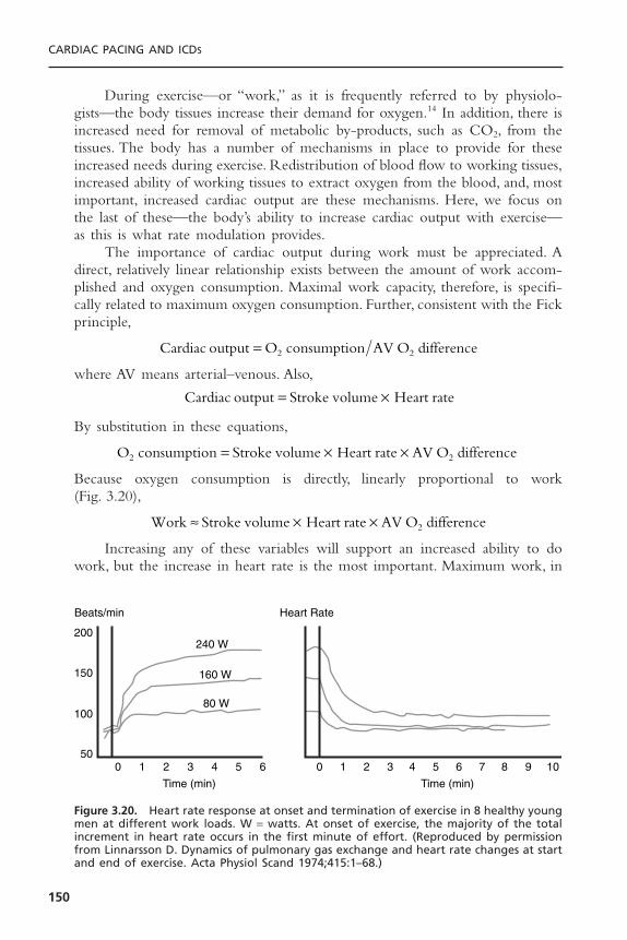
During exercise—or “work,” as it is frequently referred to by physiolo-gists—the body tissues increase their demand for oxygen.14 In addition, there isincreased need for removal of metabolic by-products, such as CO2, from thetissues. The body has a number of mechanisms in place to provide for theseincreased needs during exercise. Redistribution of blood flow to working tissues,increased ability of working tissues to extract oxygen from the blood, and, mostimportant, increased cardiac output are these mechanisms. Here, we focus onthe last of these—the body’s ability to increase cardiac output with exercise—as this is what rate modulation provides.
The importance of cardiac output during work must be appreciated. Adirect, relatively linear relationship exists between the amount of work accom-plished and oxygen consumption. Maximal work capacity, therefore, is specifi-cally related to maximum oxygen consumption. Further, consistent with the Fickprinciple,
where AV means arterial–venous. Also,
By substitution in these equations,
Because oxygen consumption is directly, linearly proportional to work (Fig. 3.20),
Increasing any of these variables will support an increased ability to dowork, but the increase in heart rate is the most important. Maximum work, in
Work Stroke volume Heart rate AV O difference2ª ¥ ¥
O consumption Stroke volume Heart rate AV O difference2 2= ¥ ¥
Cardiac output Stroke volume Heart rate= ¥
Cardiac output O consumption AV O difference2 2=
CARDIAC PACING AND ICDS
150
0 1 2 3
Time (min)
Beats/min Heart Rate
4 5 6 7 8 9 100
200
150
100
501 2 3
Time (min)
4
240 W
160 W
80 W
5 6
Figure 3.20. Heart rate response at onset and termination of exercise in 8 healthy youngmen at different work loads. W = watts. At onset of exercise, the majority of the totalincrement in heart rate occurs in the first minute of effort. (Reproduced by permissionfrom Linnarsson D. Dynamics of pulmonary gas exchange and heart rate changes at startand end of exercise. Acta Physiol Scand 1974;415:1–68.)
normal individuals, is accomplished by an increase in stroke volume to approxi-mately 150% of the resting value, an increase in heart rate to approximately300% of the resting value, and an increase in AV O2 difference by approximately250% of the resting value.These changes allow an increase in work to over ten times resting levels. In normal individuals, peak cardiac output can be increasedto 300% of resting values simply by an increase in heart rate. During peak exercise, the stroke volume is increased to approximately 150% of the restingvalue. This increase in stroke volume, as depicted in Figure 3.19, is not linearand is achieved at approximately the halfway point between the rest and maximalexercise levels. The increased stroke volume is accomplished by an increase invenous return, ventricular filling, and contractility. Loss of AV synchrony cancompromise stroke volume, even with exercise, although it appears that AV synchrony is usually less important during exercise in providing ventricularfilling than it is at rest. It is ideal, however, to optimize stroke volume becausethis is a more energy-efficient way of accomplishing cardiac output (millilitersof cardiac output/milliliters of O2 consumption) than by an increase in heartrate.
Clearly, the most important mechanism by which cardiac output isincreased during exercise is by increasing heart rate. The normal heart rateresponse to exercise follows a triphasic response (Fig. 3.20).63 Heart rate increasesmost rapidly within the first 10 to 15 seconds of exercise and reaches 70% ofthe total heart rate increased in this phase. A slower exponential rise in heartrate follows during the next 60 to 90 seconds. Finally, a slow linear increase orplateau phase finally results from sustained activity. Heart rate deceleration withcessation of exercise is generally slower than the rate acceleration and alsofollows a biphasic or triphasic response.
Advantage of Rate ModulationAs is obvious by the foregoing discussion of exercise physiology, the ability ofpatients to increase heart rate with exercise is the primary means of meetingthis and other metabolic demands. Exertional intolerance, manifested by anumber of clinical symptoms, can be very limiting, but it is almost obligatoryif heart rate cannot be increased.
In pacemaker patients, compromised ability to increase heart rate due tothe underlying cardiac electrical problem and/or superimposed drug therapy is common. The inability to increase and maintain heart rate appropriately with exercise has been called chronotropic incompetence.64 Some patients areultimately able to achieve the appropriate heart rate for the level of exercise but do so more slowly than is normal. Patients with any of these forms of chronotropic incompetence are candidates for pacing systems with rate-modulation capabilities.The diagnosis of chronotropic incompetence is relativelyeasy to make at times. Patients with third degree, and frequently lesser degrees,of AV block are typically chronotropically incompetent. The diagnosis ofchronotropic incompetence in patients with sinus node dysfunction is frequentlymore difficult. A number of different criteria have been proposed, including the
HEMODYNAMICS OF CARDIAC PACING
151

inability to increase heart rate with exercise to at least 70% to 85% of themaximum predicted heart rate (maximum predicted heart rate = 220 - age inyears). This is a useful criterion for diagnosing chronotropic incompetence, butit cannot be used in many individuals due to limitations on their exercise func-tion unrelated to cardiopulmonary status. Further, there are patients with delayedchronotropic responses who could benefit from rate-modulating pacing systemsbut might be missed by this criterion.
More complicated formulas have been developed to allow determinationof the presence of chronotropic incompetence by exercise testing with assess-ments made by stage.65 The Wilkoff chronotropic assessment exercise protocol(CAEP) is an easily performed treadmill test that has become widely used forchronotropic competency evaluation (Table 3.3). It uses gradual increases in bothelevation and speed, and can be used for the evaluation of devices with a varietyof sensor types.
Quantification of the improvement in work capacity in pacemaker popu-lations comparing non–rate-modulating with rate-modulating modes has con-sistently shown the advantages of the rate-modulating systems. Rate-modulatingpacing systems have been shown not only to improve the heart-rate responsewith exercise but also to increase work. Compared to VVI pacing,VVIR modeimproves exercise duration and cardiac index in patients undergoing paired stresstesting.66,67 These improvements are independent of patient age and ejectionfraction. Even greater improvements in exercise hemodynamics are documentedwith DDDR pacing compared to either VVIR or DDD modes.68 Compared toVVIR, DDDR pacing has demonstrated to improve exercise capacity, cardiacoutput, and cardiac metabolic indices, suggesting more efficient cardiac work.69
In patients with sick sinus syndrome, DDDR pacing provides greater maximalheart rates, exercise times, higher maximal oxygen uptake, and higher oxygen
CARDIAC PACING AND ICDS
152
Table 3.3. Chronotropic Assessment Exercise Protocol
Stage Speed (mph) Grade (%) Time (min) Cumulative Time METs
Warmup 0 1.0 0 — — 1.51 1.0 2 2.0 2.0 2.02 1.5 3 2.0 4.0 2.83 2.0 4 2.0 6.0 3.64 2.5 5 2.0 8.0 4.65 3.0 6 2.0 10.0 5.86 3.5 8 2.0 12.0 7.57 4.0 10 2.0 14.0 9.68 5.0 10 2.0 16.0 12.19 6.0 10 2.0 18.0 14.3
10 7.0 10 2.0 20.0 16.511 7.0 15 2.0 22.0 19.0
METs = metabolic equivalents.

uptake at anaerobic threshold than DDD pacing (Fig. 3.21).70 These benefitshave been attributed largely to the increased heart rate in the rate-responsivemode.
The importance of AV synchrony diminishes at higher heart rates as theearly and late diastolic filling phases converge. Nordlander and colleagues, inreview of studies addressing work capacity in rate-modulating versus non–rate-modulating systems, noted that for every 40% increase in paced rate during rate-modulated pacing compared with non–rate-modulated pacing, there is a 10%increase in work capacity.44 Despite acute hemodynamic benefits during formalexercise testing, improvements in quality of life and symptoms have not beenclearly established.
Exercise testing and assessment of improvement in maximal work capacityrepresent quantifiable parameters for assessing improvement in patients withpacemakers; but most pacemaker patients, like most normal individuals, func-tion at submaximal levels of exertion most of the time. Optimization of heartrate at these submaximal levels of exertion by providing rate modulation is theprincipal gain of enfranchising this physiologic concept. Protocols such as CAEPcan be helpful.
In Figures 3.22 and 3.23, the relative hemodynamic benefits of rate mod-ulation and stroke volume and rate modulation and AV synchrony scaled fromrest to maximum exertion can be seen for a general population. At rest, AV syn-chrony is of preeminent benefit, whereas this benefit is diminished as one
HEMODYNAMICS OF CARDIAC PACING
153
*
*Work rate (watts/min) VO2 AT (ml/kg/min)
Work rate and oxygen uptake at anaerobic threshold(sinus node disease)
VVIR SR DDD DDDR VVIR SR DDD DDDR
100
80
60
40
20
0
10
8
6
4
2
0
41± 341± 3 40 ±1
7.3 ± 0.3 7.3 ± 0.46.8±0.3
8.5 ± 0.7
49 ± 4
Figure 3.21. Work rate versus oxygen uptake at anaerobic threshold in 9 patients withsinus node dysfunction. Each patient underwent testing in sinus rhythm (SR), VVIR, DDDand DDDR pacing modes using a respiratory sensor pacemaker. Oxygen uptake wasgreater in DDDR mode compared to all others at anaerobic threshold. (Reproduced bypermission from Lemke B, et al. Aerobic capacity in rate modulated pacing. PACE1992;15:1914–1918.)
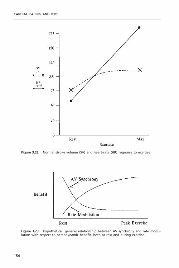
CARDIAC PACING AND ICDS
154
Figure 3.22. Normal stroke volume (SV) and heart-rate (HR) response to exercise.
Figure 3.23. Hypothetical, general relationship between AV synchrony and rate modu-lation with respect to hemodynamic benefit, both at rest and during exercise.

approaches maximal exercise, especially in relationship to rate modulation. Ratemodulation is of very little value at rest, but it becomes quite important earlyin exercise and increases in relative benefit approaching maximal exercise. Ratemodulation and AV synchrony are complementary, not competitive, physiologicconcepts.
MODE SELECTION AND STRATEGIES TO MINIMIZE VENTRICULAR PACING
Selection of the appropriate bradyarrhythmia pacing mode to fit the patient’selectrical and hemodynamic status is usually not difficult. Striving to provideboth AV synchrony and rate modulation, when clinical evidence supports abenefit, assists in this decision-making process.44,48 Mode-selection decisionsrelated to electrical considerations take into account three principal issues: atrialrhythm status, status of AV conduction, and presence of chronotropic compe-tence. An expanding indication for chronotropic support includes heart failurepatients who meet criteria for cardiac resynchronization therapy. A mode selec-tion flow chart is shown in Figure 3.24.
Difficulties may arise in the assessment of atrial rhythm status; however, theavailability of mode switching functions in most devices has rendered the pres-ence of atrial arrhythmias relatively inconsequential in all but cases of chronic
HEMODYNAMICS OF CARDIAC PACING
155
Atrial Rhythm
Persistent/ChronicAtrial Tachyarrhythmia
Paroxysmal Atrial Tachyarrhythmiaor Sinus Node Dysfunction
Adequate ChronotropicResponse to Exercise or
Intermittent AV Block
Inadequate ChronotropicResponse to Exercise or
Complete AV Block
Normal AV Conduction(Present or Anticipated)
Abnormal AV Conduction(Present or Anticipated)
CHF NYHA III–IVQRS > 120msLVEF < 35%
CHF NYHA III–IVQRS > 120msLVEF < 35%
ChronotropicResponse
Adequate Inadequate Adequate Inadequate
ChronotropicResponse
DDDRDDD
Bi-V DDD(R)Bi-V VVV(R)
AAIRVVIRVVI AAI
Figure 3.24. Mode-choice algorithm based on the presence and persistence of atrialtachyarrhythmias, status of AV conduction, and adequacy of chronotropic response toexercise. VVI = ventricular demand pacing, VVIR = rate-modulated ventricular demandpacing, DDD = AV universal pacing, DDDR = rate-modulated AV universal pacing, AAI =atrial demand pacing, AAIR = rate-modulated atrial demand pacing, Bi-V = biventricular,(R) with or without rate-modulation. (Pacemaker codes are discussed in detail in Chapter6.)
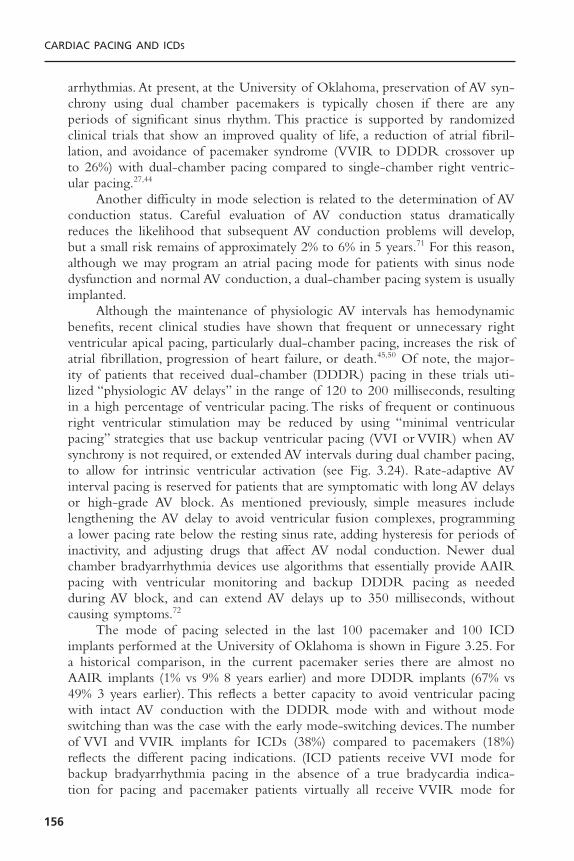
arrhythmias. At present, at the University of Oklahoma, preservation of AV syn-chrony using dual chamber pacemakers is typically chosen if there are anyperiods of significant sinus rhythm. This practice is supported by randomizedclinical trials that show an improved quality of life, a reduction of atrial fibril-lation, and avoidance of pacemaker syndrome (VVIR to DDDR crossover upto 26%) with dual-chamber pacing compared to single-chamber right ventric-ular pacing.27,44
Another difficulty in mode selection is related to the determination of AVconduction status. Careful evaluation of AV conduction status dramaticallyreduces the likelihood that subsequent AV conduction problems will develop,but a small risk remains of approximately 2% to 6% in 5 years.71 For this reason,although we may program an atrial pacing mode for patients with sinus nodedysfunction and normal AV conduction, a dual-chamber pacing system is usuallyimplanted.
Although the maintenance of physiologic AV intervals has hemodynamicbenefits, recent clinical studies have shown that frequent or unnecessary rightventricular apical pacing, particularly dual-chamber pacing, increases the risk ofatrial fibrillation, progression of heart failure, or death.45,50 Of note, the major-ity of patients that received dual-chamber (DDDR) pacing in these trials uti-lized “physiologic AV delays” in the range of 120 to 200 milliseconds, resultingin a high percentage of ventricular pacing. The risks of frequent or continuousright ventricular stimulation may be reduced by using “minimal ventricularpacing” strategies that use backup ventricular pacing (VVI or VVIR) when AVsynchrony is not required, or extended AV intervals during dual chamber pacing,to allow for intrinsic ventricular activation (see Fig. 3.24). Rate-adaptive AVinterval pacing is reserved for patients that are symptomatic with long AV delaysor high-grade AV block. As mentioned previously, simple measures includelengthening the AV delay to avoid ventricular fusion complexes, programminga lower pacing rate below the resting sinus rate, adding hysteresis for periods ofinactivity, and adjusting drugs that affect AV nodal conduction. Newer dualchamber bradyarrhythmia devices use algorithms that essentially provide AAIRpacing with ventricular monitoring and backup DDDR pacing as neededduring AV block, and can extend AV delays up to 350 milliseconds, withoutcausing symptoms.72
The mode of pacing selected in the last 100 pacemaker and 100 ICDimplants performed at the University of Oklahoma is shown in Figure 3.25. Fora historical comparison, in the current pacemaker series there are almost noAAIR implants (1% vs 9% 8 years earlier) and more DDDR implants (67% vs49% 3 years earlier). This reflects a better capacity to avoid ventricular pacingwith intact AV conduction with the DDDR mode with and without modeswitching than was the case with the early mode-switching devices.The numberof VVI and VVIR implants for ICDs (38%) compared to pacemakers (18%)reflects the different pacing indications. (ICD patients receive VVI mode forbackup bradyarrhythmia pacing in the absence of a true bradycardia indica-tion for pacing and pacemaker patients virtually all receive VVIR mode for
CARDIAC PACING AND ICDS
156
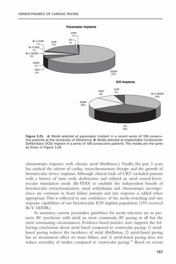
chronotropic response with chronic atrial fibrillation.) Finally, the past 3 yearshas marked the advent of cardiac resynchronization therapy and the growth ofbiventricular device implants. Although clinical trials of CRT excluded patientswith a history of sinus node dysfunction and utilized an atrial sensed-biven-tricular stimulation mode (Bi-VDD) to establish the independent benefit ofbiventricular resynchronization, atrial arrhythmias and chronotropic incompe-tence are common in heart failure patients and rate response is added whenappropriate.This is reflected in our confidence of the mode-switching and rateresponse capabilities of our biventricular ICD implant population (33% receivedBi-V DDDR).
In summary, current pacemaker guidelines for mode-selection are to pre-serve AV synchrony with atrial or, most commonly, AV pacing in all but themost extenuating circumstances. Evidence-based practice now supports the fol-lowing conclusions about atrial based compared to ventricular pacing: 1) atrial-based pacing reduces the incidence of atrial fibrillation, 2) atrial-based pacinghas an inconsistent effect on heart failure, and 3) atrial-based pacing does notreduce mortality of strokes compared to ventricular pacing.44 Based on recent
HEMODYNAMICS OF CARDIAC PACING
157
Pacemaker Implants
ICD Implants
DDDR67%
DDD6%
VDDR1%
Bi–V DDDR5%
Bi–V DDD1%
Bi–V VVIR1%
VVIR17%
VVI1%
AAIR1%
Bi–V DDDR33%
VVI33%
DDDR20%
DDD9%
VVIR5%
Figure 3.25. A: Mode selected at pacemaker implant in a recent series of 100 consecu-tive patients at the University of Oklahoma. B: Mode selected at Implantable CardioverterDefibrillator (ICD) implant in a series of 100 consecutive patients. The modes are the sameas those in Figure 3.24.
evidence, there is growing concern that continuous right ventricular pacingincreases the risk of heart failure progression; therefore, all attempts to avoidunnecessary right ventricular pacing by implementing strategies to preservenormal ventricular activation are recommended. It is quite possible that studiescurrently in progress will lead to a more widespread use of biventricular pacingwhenever significant ventricular stimulation is anticipated. Further, we judge thepatient’s chronotropic response capabilities; and when symptoms or heart failureare exacerbated by a blunted or absent rate response, we treat using devices withsimple, automatic but appropriate physiologic sensors.
REFERENCES1. Harvey W. Exercitatio anatomica de motu cordis et sanguinis in animalibus (1628).
R Willis, translator. England: Barnes Survey, 1874.2. Lewis T. Fibrillation of the auricles: its effects upon the circulation. J Exp Med
1912;16:395–398.3. Gesel RA. Auricular systole and its relation to ventricular output. Am J Physiol
1911;29:32–63.4. Reynolds DW, Olson EG, Burow RD, et al. Hemodynamic evaluation of atrioven-
tricular and ventriculoatrial pacing. Pacing Clin Electrophysiol 1984;7:463.5. Erlebacher JA, Danner RL, Stelzer PE. Hypotension with ventricular pacing:
an atrial vasodepressor reflex in human beings. J Am Coll Cardiol 1984;4:550–555.
6. Alicandri C, Fouad FM, Tarazi RC, et al. Three cases of hypotension and syncopewith ventricular pacing: possible role of atrial reflexes. Am J Cardiol 1978;42:137–142.
7. Goldreyer B, Bigger T. Ventriculoatrial conduction in man. Circulation 1970;41:935–946.
8. Klementowicz P, Ausubel K, Furman S.The dynamic nature of ventriculoatrial con-duction. Pacing Clin Electrophysiol 1986;9:1050–1054.
9. Levy S, Corbelli JL, Labrunie P. Retrograde (ventriculoatrial) conduction. PacingClin Electrophysiol 1983;6:364–371.
10. Petersen MEV, Chamberlain-Webber R, Fitzpatrick AP, et al. Permanent pacing forcardioinhibitory malignant vasovagal syndrome. Br Heart J 1994;71:274–281.
11. Karloff I. Hemodynamic effect of atrial triggered vs. fixed rate pacing at rest andduring exercise in complete heart block. Acta Med Scand 1975;197:195–210.
12. Greenberg B, Chatterjee K, Parmley WW, et al. The influence of left ventricularfilling pressure on atrial contribution to cardiac output. Am Heart J 1979;98:742–751.
13. Kruse I, Arnman K, Conradson TB, Ryden L. A comparison of the acute and long-term hemodynamic effects of ventricular inhibited and atrial synchronous ventric-ular inhibited pacing. Circulation 1982;675:846–855.
14. Astrand PO, Rodahl K.Textbook of work physiology. 2nd ed. New York: McGraw-Hill, 1977.
15. Topol E, Goldschlager N, Ports TA, et al. Hemodynamic benefit of atrial pacing inright ventricular myocardial infarction. Ann Intern Med 1982;96:594–597.
16. Hartzler GO, Maloney JD, Curtis JJ, Barnhorst DA. Hemodynamic benefits of atrio-ventricular sequential pacing after surgery. Am J Cardiol 1977;40:232–236.
CARDIAC PACING AND ICDS
158

17. Chamberlain DA, Leinbach RC,Vassaux CE, et al. Sequential atrioventricular pacingin heart block complicating acute myocardial infarction. N Engl J Med 1970;282:577–582.
18. Reynolds DW, Wilson MF, Burow RD, et al. Hemodynamic evaluation of atrioventricular sequential vs. ventricular pacing in patients with normal and poorventricular function at variable heart rates and posture. J Am Coll Cardiol1983;1:636.
19. Ogawa S, Dreifus LS, Shenoy PN, et al. Hemodynamic consequences of atrioven-tricular and ventriculoatrial pacing. Pacing Clin Electrophysiol 1978;1:8–15.
20. Morgan DE, Norman R, West RO, Burggraf G. Echocardiographic assessment oftricuspid regurgitation during ventricular demand pacing. Am J Cardiol 1986;58:1025–1029.
21. Reynolds DW, Olson EG, Burrow RD, et al. Mitral regurgitation during atrioven-tricular and ventriculoatrial pacing. Pacing Clin Electrophysiol 1984;7:476.
22. Nakaoka H, Kitahara Y, Imataka K, et al. Atrial natriuretic peptide with artificialpacemakers. Am J Cardiol 1987;60:384–385.
23. Ellenbogen KA, Wood MA, Stambler BS. Pacemaker syndrome: clinical, hemody-namic and neurohumoral features. In: Barold SS, Mugica J, eds. New perspectives incardiac pacing 3. Armonk, NY: Futura Publishing, 1993:85–112.
24. Alpert M, Curtis J, Sanfelippo J, et al. Comparative survival after permanent ven-tricular and dual-chamber pacing for patients with chronic high degree atrioven-tricular block with and without preexistent congestive heart failure. J Am CollCardiol 1986;7:925–932.
25. Rosenqvist M, Brandt J, Schuller H. Long-term pacing in sinus node disease: effectsof stimulation mode on cardiovascular morbidity and mortality. Am Heart J1988;116:16–22.
26. Connolly SJ, Kerr CR, Gent M, et al. Effects of physiologic pacing versus ven-tricular pacing on the risk of stroke and death due to cardiovascular causes.Candadian Trial of Physiologic Pacing Investigators. N Engl J Med 2000;342:1385–1391.
27. Lamas GA, Lee KL, Sweeney MO, et al.Ventricular pacing or dual-chamber pacingfor sinus-node dysfunction. N Engl J Med 2002;346:1854–1862.
28. Haskell RJ, French WJ. Optimum AV interval in dual-chamber pacemakers. PacingClin Electrophysiol 1986;9:670–675.
29. Janosik DL, Pearson AC, Buckingham TA, et al. The hemodynamic benefit of dif-ferential atrioventricular delay intervals for sensed and paced atrial events duringphysiologic pacing. J Am Coll Cardiol 1989;14:499–507.
30. Luceri RM, Brownstein SL,Vardeman L, Goldstein S. PR interval behavior duringexercise: implications for physiological pacemakers. Pacing Clin Electrophysiol1990;13:1719–1723.
31. Alt E, von Bibra H, Blomer H. Different beneficial AV intervals with DDD pacingafter sensed or paced atrial events. J Electrophysiol 1987;1:250–256.
32. Reynolds DW, Olson EG, Burow RD, et al. Atrial vs. atrioventricular pacing: ahemodynamic comparison. Pacing Clin Electrophysiol 1985;8:148.
33. Leclercq C, Gras D, Le Helloco A, et al. Hemodynamic importance of preservingthe normal sequence of ventricular activation in permanent pacing. Am Heart J1995;129:1133.
34. Santomauro M, Fazio S, Ferraro S, et al. Fourier analysis in patients with differentpacing modes. PACE 1991;14:1351.
HEMODYNAMICS OF CARDIAC PACING
159

35. Hass JM, Strait GB. Pacemaker induced cardiovascular failure: hemodynamic andangiographic observations. Am J Cardiol 1974;33:295–299.
36. Ausubel K, Boal BH, Furman S. Pacemaker syndrome: definition and evaluation.Clin Cardiol 1985;3:587–594.
37. Deshmukh P, Casavant DA, Romanyshyn M, Anderson K. Permanent direct His-bundle pacing: a novel approach to cardiac pacing in patients with normal His-Purkinje activation. Circulation 2000;101:869–877.
38. Gold MR, Brockman R, Peters RW, et al. Acute hemodynamic effects of right ven-tricular pacing site and pacing mode in patients with congestive heart failure sec-ondary to either ischemic or idiopathic dilated cardiomyopathy. Am J Cardiol2000;85:1106–1109.
39. Gold MR, Shorofsky SR, Metcalf MD, et al. The acute hemodynamic effects ofright ventricular septal pacing in patients with congestive heart failure secondary toischemic or idiopathic dilated cardiomyopathy. Am J Cardiol 1997;79:679–681.
40. Bourke JP, Hawkins T, Keavey P, et al. Evolution of ventricular function during per-manent pacing from either right ventricular apex or outflow tract following AV-junctional ablation for atrial fibrillation. Europace 2002;4:219–28.
41. Tse HF,Yu C,Wong KK, et al. Functional abnormalities in patients with permanentright ventricular pacing: the effect of sites of electrical stimulation. J Am Coll Cardiol2002;40:1451–1458.
42. Giudici MC, Thornburg GA, Buck DL, et al. Comparison of right ventricularoutflow tract and apical lead permanent pacing on cardiac output. Am J Cardiol1997;79:209–212.
43. Stambler BS, Ellenbogen K, Zhang X, et al. Right ventricular outflow versus apicalpacing in pacemaker patients with congestive heart failure and atrial fibrillation. JCardiovasc Electrophysiol 2003;14:1180–1186.
44. Lamas GA, Ellenbogen KA, Hennekens CH, Montanez A. Evidence base for pace-maker mode selection from physiology and randomized trials. Circulation2004;109:443–451.
45. Schwaab B, Frohlig G, Alexander C, et al. Influence of right ventricular stimulationsite on left ventricular function in atrial synchronous ventricular pacing. J Am CollCardiol 1999;33:317–323.
46. Sweeney MO, Hellkamp AS, Ellenbogen KA, et al. Adverse effect of ventricularpacing on heart failure and atrial fibrillation among patients with normal baselineQRS duration in a clinical trial of pacemaker therapy for sinus node dysfunction.Circulation 2003;107:2932–2937.
47. Tantengco MV,Thomas RL, Karpawich PP. Left ventricular dysfunction after long-term right ventricular apical pacing in the young. J Am Coll Cardiol 2001;37:2093–2100.
48. Gregoratos G, Abrams J, Epstein AE, et al. ACC/AHA/NASPE 2002 guidelineupdate for implantation of cardiac pacemakers and antiarrhythmia devices: summaryarticle: a report of the American College of Cardiology/American Heart Associa-tion Task Force on Practice Guidelines (ACC/AHA/NASPE Committee to Updatethe 1998 Pacemaker Guidelines). Circulation 2002;106:2145–2161.
49. Moss A, Zareba W, Hall W, et al. for the Multicenter Automatic Defibrillator Implan-tation Trial II Investigators. Prophylactic implantation of a defibrillator in patientswith myocardial infarction and reduced ejection fraction. N Engl J Med2002;346:877–883.
CARDIAC PACING AND ICDS
160
50. Wilkoff BL, Cook JR, Epstein AE, et al. Dual-chamber pacing or ventricular backuppacing in patients with an implantable defibrillator: the Dual Chamber and VVIImplantable Defibrillator (DAVID) Trial. JAMA 2002;288:3115–3123.
51. Jeanrenaud X, Goy JJ, Kappenberger L. Effects of dual-chamber pacing in hyper-trophic cardiomyopathy. Lancet 1992;339:1318–1323.
52. Fananapazir L, Cannon RO, Tripodi D, Panza JA. Impact of dual-chamber perma-nent pacing in patients with obstructive hypertrophic cardiomyopathy with symp-toms refractory to verapamil and b-adrenergic blocker therapy. Circulation1992;85:2149–2161.
53. Fananapazir L, Epstein ND, Curiel RV, et al. Long-term results of dual-chamber(DDD) pacing in obstructive hypertrophic cardiomyopathy. Evidence for progressivesymptomatic and hemodynamic improvement and reduction of left ventricularhypertrophy. Circulation 1994;90:2731–2742.
54. Nishimura RA, Trusty JM, Hayes DL, et al. Dual-chamber pacing for hypertrophiccardiomyopathy: a randomized, double-blind, crossover trial. J Am Coll Cardiol1997;29:435–441.
55. Simantirakis EN, Kanoupakis EM, Kochiadakis GE, et al.The effect of DDD pacingon ergospirometric parameters and neurohormonal activity in patients with hyper-trophic obstructive cardiomyopathy. Pacing Clin Electrophysiol 1998;21:2269–2272.
56. Maron BJ, Olivotto I, Spirito P, et al. Epidemiology of hypertrophic cardiomyopa-thy related death: revisited in a large non-referral-based patient population. Circu-lation 2000;102:858–864.
57. Auricchio A, Stellbrink C, Block M, et al. Effect of pacing chamber and atrioven-tricular delay on acute systolic function of paced patients with congestive heartfailure. The pacing therapies for congestive heart failure study group. Circulation1999;99:2993–3001.
58. Kass DA, Chen CH, Curry C, et al. Improved left ventricular mechanics from acuteVDD pacing in patients with dilated cardiomyopathy and ventricular conductiondelay. Circulation 1999;99:1567–1573.
59. Saxon LA, Kerwin WF, DeMarco T, et al. Acute effects of AV synchronous biven-tricular pacing on left atrial to left ventricular activation/contraction sequence indilated cardiomyopathy. J Cardiac Failure 1998;4:138.
60. Kerwin WF, Botvinick EH, O’Connell JW, et al.Ventricular contraction abnormal-ities in dilated cardiomyopathy: effect of biventricular pacing to correct interven-tricular dyssynchrony. J Am Coll Cardiol 2000;35:1121–1227.
61. Cazeau S, Gras D, Lazarus A, et al. Multisite stimulation for correction of cardiacasynchrony. Heart 2000;84:579–581.
62. Leon AR, Greenberg JM, Kanuru N, et al. Cardiac resynchronization in patientswith congestive heart failure and chronic atrial fibrillation: effect of upgrading tobiventricular pacing after chronic right ventricular pacing. J Am Coll Cardiol2002;39:1258–1263.
63. Linnarsson D. Dynamics of pulmnary gas exchange and heart rate changes at startand end of exercise. Acta Physiol Scand 1974;415:1–68.
64. Ellestad MH,Wan MKC. Predictive implications of stress testing: follow-up of 2700subjects after maximum treadmill testing. Circulation 1975;51:363–369.
65. Wilkoff BL, Corey J, Blackburn G. A mathematical model of the cardiac chrono-tropic response to exercise. J Electrophysiol 1989;3:176–180.
HEMODYNAMICS OF CARDIAC PACING
161
66. Buckingham TA, Woodruff RC, Pennington DG, et al. Effect of ventricular func-tion on the exercise hemodynamics of variable rate pacing. J Am Coll Cardiol1988;11:1269.
67. Lau CP, Camm J. Role of left ventricular function and Doppler derived variablesin predicting hemodynamic benefits of rate-responsive pacing. Am J Cardiol1988;62:174.
68. Proctor EE, Leman RB, Mann DL, et al. Single-versus dual-chamber sensor-drivenpacing: Comparison of cardiac outputs. Am Heart J 1991;122:728.
69. Jutzy RV, Florio J, Isaeff DM, et al. Limitations of testing methods for evaluation ofdual-chamber versus single-chamber adaptive rate pacing. Am J Cardiol 1991;61:1715.
70. Cappuci A, Boriani G, Speechia S, et al. Evaluation by cardiopulmonary exercisetesting of DDDR versus DDD pacing. PACE 1992;15:1908.
71. Santini M, Aexidou G, Ansalone G, et al. Relation of prognosis in sick sinus syn-drome to age, conduction defects, and modes of permanent cardiac pacing. Am JCardiol 1990;65:729–735.
72. Sweeney MO, Shea JV, Fox V, et al. Randomized trial of a new minimal ventricu-lar pacing mode in patients with dual chamber ICDs. PACE 2003;26:973.
CARDIAC PACING AND ICDS
162
163
Temporary cardiac pacing serves as the definitive therapy for the acute man-agement of medically refractory bradyarrhythmias. The applications of tempo-rary pacing also include management of certain tachyarrhythmias and use inprovocative diagnostic cardiac procedures. It is essential for cardiologists, inten-sivists, and emergency room personnel to be familiar with temporary pacing.The indications for temporary pacing are given in Chapter 1. The purpose ofthis chapter is to describe the salient clinical aspects of the temporary pacingtechniques currently in use.
TRANSCUTANEOUS CARDIAC PACINGTranscutaneous cardiac pacing has emerged as the preeminent initial mode ofcardiac pacing for bradyasystolic arrest situations and prophylactic pacing appli-cations. The technique can be quickly and safely initiated by minimally trainedpersonnel. A variable incidence of cardiac capture and poor patient tolerancerepresent the disadvantages to transcutaneous pacing.
Transcutaneous cardiac pacing produces depolarization of myocardial tissueby pulsed electrical current conducted through the chest between electrodesadherent to the skin. The self-adhesive surface patch electrodes are large—typ-ically 8cm in diameter—nonmetallic, and impregnated with a high-impedanceconductive gel. Transcutaneous pacing generators are usually incorporated intoexternal defibrillator units (Fig. 4.1). These units provide up to 200mA ofcurrent and use a rectangular or truncated exponential pulse waveform of 20to 40 milliseconds duration. The long pulse widths permit the lowest pacingthresholds while minimizing the stimulation of skeletal muscle and cutaneousnerves.
To initiate transcutaneous pacing, the patch electrodes are secured anteri-orly and posteriorly to the chest wall. Several electrode configurations have beenrecommended and appear to be equally effective in healthy subjects.1 For effec-tive capture, it is essential that the anterior chest electrode be of negative polar-ity. Thresholds may be unobtainable or intolerably painful if the negative
4Temporary Cardiac Pacing
Mark A. Wood and Kenneth A. Ellenbogen
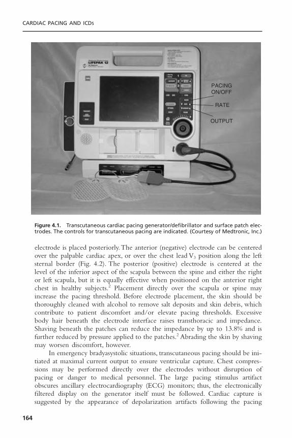
electrode is placed posteriorly.The anterior (negative) electrode can be centeredover the palpable cardiac apex, or over the chest lead V3 position along the leftsternal border (Fig. 4.2). The posterior (positive) electrode is centered at thelevel of the inferior aspect of the scapula between the spine and either the rightor left scapula, but it is equally effective when positioned on the anterior rightchest in healthy subjects.2 Placement directly over the scapula or spine mayincrease the pacing threshold. Before electrode placement, the skin should bethoroughly cleaned with alcohol to remove salt deposits and skin debris, whichcontribute to patient discomfort and/or elevate pacing thresholds. Excessivebody hair beneath the electrode interface raises transthoracic and impedance.Shaving beneath the patches can reduce the impedance by up to 13.8% and isfurther reduced by pressure applied to the patches.2 Abrading the skin by shavingmay worsen discomfort, however.
In emergency bradyasystolic situations, transcutaneous pacing should be ini-tiated at maximal current output to ensure ventricular capture. Chest compres-sions may be performed directly over the electrodes without disruption ofpacing or danger to medical personnel. The large pacing stimulus artifactobscures ancillary electrocardiography (ECG) monitors; thus, the electronicallyfiltered display on the generator itself must be followed. Cardiac capture is suggested by the appearance of depolarization artifacts following the pacing
CARDIAC PACING AND ICDS
164
PACINGON/OFF
RATE
OUTPUT
Figure 4.1. Transcutaneous cardiac pacing generator/defibrillator and surface patch elec-trodes. The controls for transcutaneous pacing are indicated. (Courtesy of Medtronic, Inc.)
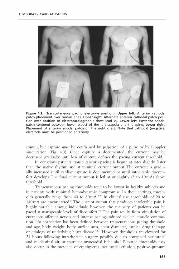
stimuli, but capture must be confirmed by palpation of a pulse or by Dopplerauscultation (Fig. 4.3). Once capture is documented, the current may bedecreased gradually until loss of capture defines the pacing current threshold.
In conscious patients, transcutaneous pacing is begun at rates slightly fasterthan the native rhythm and at minimal current output. The current is gradu-ally increased until cardiac capture is documented or until intolerable discom-fort develops. The final current output is left at or slightly (5 to 10mA) abovethreshold.
Transcutaneous pacing thresholds tend to be lowest in healthy subjects andin patients with minimal hemodynamic compromise. In these settings, thresh-olds generally range from 40 to 80mA.3–6 In clinical use, thresholds of 20 to140mA are encountered.5 The current output that produces intolerable pain ishighly variable among individuals; however, the majority of patients can bepaced at manageable levels of discomfort.4,5 The pain results from stimulation ofcutaneous afferent nerves and intense pacing-induced skeletal muscle contrac-tion. No correlation has been defined between transcutaneous pacing thresholdand age, body weight, body surface area, chest diameter, cardiac drug therapy,or etiology of underlying heart disease.4,5,7 However, thresholds are elevated for24 hours following intrathoracic surgery, possibly due to entrapped pericardialand mediastinal air, or transient myocardial ischemia.7 Elevated thresholds mayalso occur in the presence of emphysema, pericardial effusion, positive-pressure
TEMPORARY CARDIAC PACING
165
Figure 4.2. Transcutaneous pacing electrode positions. Upper left: Anterior cathodalpatch placement over cardiac apex. Upper right: Alternate anterior cathodal patch posi-tion over position of electrocardiographic chest lead V3. Lower left: Posterior anodalpatch centered between lower aspect of the left scapula and the spine. Lower right:Placement of anterior anodal patch on the right chest. Note that cathodal (negative)electrode must be positioned anteriorly.

ventilation, and when used to pace terminate ventricular tachycardias.5,8,9 As withother forms of cardiac pacing, thresholds tend to be higher and incidence ofcapture lower during prolonged or delayed resuscitation efforts.Thresholds maydecrease after adequate myocardial perfusion is restored, however.
Electrophysiologically, transcutaneous pacing affects ventricular pacing inhumans.9,10 Retrograde activation of the atria may occur. Intracardiac, electro-cardiographic, and pressure monitoring during transcutaneous pacing haveshown the right ventricle to be the site of earliest myocardial activation.9,10 The-oretically, this follows from the proximity of the right ventricle to the anterior(negative) electrode and from the fact that the stimulating current densitydeclines proportionally to the square of distance from the electrode. Despiteinitial right ventricular activation, echocardiographic studies in healthy subjectsundergoing transcutaneous pacing have shown normal synchronous left ven-tricular contraction without alterations in ventricular end-diastolic dimension or
CARDIAC PACING AND ICDS
166
Figure 4.3. Successful transcutaneous cardiac pacing during complete heart block. A:Complete heart block with wide complex ventricular escape rhythm (a = atrial depolar-ization; v = ventricular depolarization). B: Subthreshold transcutaneous pacing stimuli (p)at 20mA fail to capture the ventricle. C: A 1:1 ventricular capture achieved with increasedgenerator current output to 60mA. Ventricular capture was confirmed by palpation offemoral pulses.
fractional shortening when compared to sinus rhythm.3 This pattern suggestsnear-simultaneous activation of the entire left ventricle. When measured at ornear the transcutaneous pacing threshold, ventricular effective refractory periodsmay be significantly longer than values obtained during right ventricular endo-cardial stimulation.4
Modest reductions in left ventricular systolic pressure and stroke index mayoccur during transcutaneous pacing when compared to sinus rhythm or atrio-ventricular (AV) sequential pacing as a result of AV dyssynchrony.11 The alter-ations in systemic pressures are similar to those induced by endocardialventricular demand inhibited pacing. Right heart pressures may increase due toloss of AV synchrony. Compared with atrial or ventricular endocardial pacing,transcutaneous pacing reportedly provides greater cardiac output and systolicindices.10 This phenomenon has been associated with an increased O2 con-sumption during transcutaneous pacing and is believed to result from enhancedskeletal muscle metabolism secondary to electrical stimulation. Systemic vascu-lar resistance appears to be unaltered, however. Alternatively, the enhancedcardiac output from transcutaneous pacing may result from chest, diaphragmatic,and abdominal muscle contractions simulating cough-induced resuscitation syn-chronized to cardiac activation.12
The incidence of ventricular capture with transcutaneous pacing is greatlyinfluenced by the setting in which it is used. In healthy subjects, the ability tocapture and tolerate transcutaneous pacing is high, ranging from 50% to100%.4,9,13 Clinically, success rates appear to be highest when transcutaneouspacing is used prophylactically or early (within 5 minutes) in the course ofbradycardic arrests.5 In these situations, success rates may exceed 90%.5 In emer-gency situations, the success of transcutaneous pacing is lower, but ranges from10% to 93%.1,5,14 In the largest study, Zoll and co-workers report ventricularcapture in 105 of 134 patients (78%) in diverse clinical situations.5 Electricalcapture was obtained in only 58% of cardiac arrests but in 95% of cases of pro-phylactic use. Transcutaneous pacing has been used continuously in humans forup to 108 hours and intermittently for 17 days without complications.5,15 Thispacing mode has been used to terminate both ventricular and supraventriculartachycardia.14,16
A variety of causes may contribute to failure of transcutaneous pacing.These are outlined with possible solutions in Table 4.1. The causes of exces-sively painful pacing and their corrections are listed in Table 4.2.
In more than 40 years of experience, complications related to transcuta-neous pacing have been extraordinarily rare. Although limited areas of focalmyofibrillar coagulation necrosis and perivascular microinfarcts have beendemonstrated in dogs undergoing transcutaneous pacing, no such lesions havebeen described in humans.9 Transcutaneous pacing produces no measurablerelease of myoglobin, myocardial creatine kinase, or myocardial lactate dehydro-genase in normal individuals.3 There are no reports of damage to skeletal muscle,lungs, myocardium, or skin (other than mild erythema and irritation) associatedwith transcutaneous pacing in humans. Caution has been suggested in using
TEMPORARY CARDIAC PACING
167
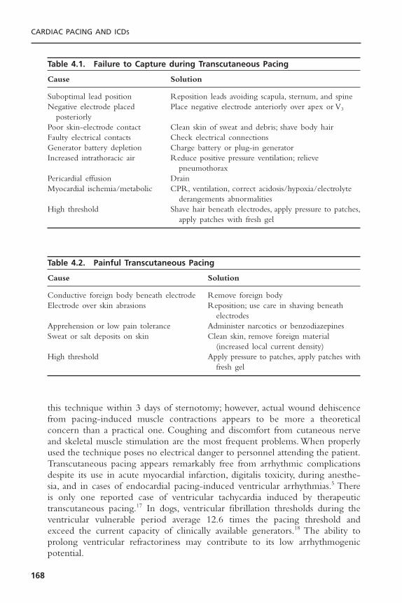
this technique within 3 days of sternotomy; however, actual wound dehiscencefrom pacing-induced muscle contractions appears to be more a theoreticalconcern than a practical one. Coughing and discomfort from cutaneous nerveand skeletal muscle stimulation are the most frequent problems. When properlyused the technique poses no electrical danger to personnel attending the patient.Transcutaneous pacing appears remarkably free from arrhythmic complicationsdespite its use in acute myocardial infarction, digitalis toxicity, during anesthe-sia, and in cases of endocardial pacing-induced ventricular arrhythmias.5 Thereis only one reported case of ventricular tachycardia induced by therapeutic transcutaneous pacing.17 In dogs, ventricular fibrillation thresholds during theventricular vulnerable period average 12.6 times the pacing threshold andexceed the current capacity of clinically available generators.18 The ability toprolong ventricular refractoriness may contribute to its low arrhythmogenicpotential.
CARDIAC PACING AND ICDS
168
Table 4.1. Failure to Capture during Transcutaneous Pacing
Cause Solution
Suboptimal lead position Reposition leads avoiding scapula, sternum, and spineNegative electrode placed Place negative electrode anteriorly over apex or V3
posteriorlyPoor skin-electrode contact Clean skin of sweat and debris; shave body hairFaulty electrical contacts Check electrical connectionsGenerator battery depletion Charge battery or plug-in generatorIncreased intrathoracic air Reduce positive pressure ventilation; relieve
pneumothoraxPericardial effusion DrainMyocardial ischemia/metabolic CPR, ventilation, correct acidosis/hypoxia/electrolyte
derangements abnormalitiesHigh threshold Shave hair beneath electrodes, apply pressure to patches,
apply patches with fresh gel
Table 4.2. Painful Transcutaneous Pacing
Cause Solution
Conductive foreign body beneath electrode Remove foreign bodyElectrode over skin abrasions Reposition; use care in shaving beneath
electrodesApprehension or low pain tolerance Administer narcotics or benzodiazepinesSweat or salt deposits on skin Clean skin, remove foreign material
(increased local current density)High threshold Apply pressure to patches, apply patches with
fresh gel
TRANSVENOUS PACING
Transvenous pacing provides the most consistent and reliable means of tempo-rary cardiac pacing in clinical practice. The technique permits reliable atrialand/or ventricular pacing, a feature unique to this modality. Once initiated,pacing is generally stable and extremely well tolerated. Considerable knowledgeand technical skills are required to implement transvenous pacing safely andeffectively, however.19 Even so, a variety of complications may attend its use.Theprocedure also requires significant time to implement, making it less than idealfor emergency situations.
Transvenous cardiac pacing uses intravenous catheter electrodes to stimu-late atrial or ventricular myocardial tissue directly with electrical current pulsesprovided by an external generator. Stimulation may be accomplished by bipolarelectrode configurations—in which both anode and cathode are intracardiac inlocation; or by unipolar pacing—in which one pole, preferably the anode, isextracardiac in location. The bipolar configuration is most commonly used fortemporary pacing, and a variety of pacing leads are available (Fig. 4.4). Thesecatheters are typically 3 to 6F in diameter, use platinum-coated electrodes, andare constructed of flexible plastic. These catheters may be flaccid and flow-directed (floating) by means of an inflatable balloon between the electrodes, orthey may be semirigid (semifloating) without balloons for more responsivemanipulation. Semirigid catheters may be straight or possess preformed distalcurvatures ( J configurations) to facilitate manipulation and stable atrial posi-tioning.Temporary screw-in pacing leads have been introduced to enhance leadstability.20,21 These leads have been used for prolonged pacing up to 32 days andpermit ambulatory temporary pacing (see Fig. 4.4B).20–22 Alternatively, screw-inpermanent pacing electrodes may be introduced percutaneously for prolongedpacing.
Other specialized electrode designs include single-pass dual-chamber pacingleads and pulmonary artery catheters with proximal atrial and/or distal ventric-ular electrodes (Figs. 4.4 and 4.5). Lead stability may be problematic with pacingpulmonary artery catheters, however.
Temporary pacing generators are typically constant-current output devices(Fig. 4.6).These generators are designed to function against loads of 300 to 1000ohms.The stimulus pulse width is usually 1 to 2 milliseconds.Temporary pacinggenerators typically feature adjustable rates (30 to 180 pulses per minute [ppm]),sensitivity (0.1 mV-asynchronous), and current output (0.1 to 20mA). Tempo-rary universal (DDD) generators provide a variety of programmability and arecapable of most common single- and dual-chamber pacing modes as well ashigh-rate pacing for arrhythmia termination.
Decisions regarding the site of venous access for pacing should take intoconsideration the urgency to initiate pacing, desired lead stability, need to avoidspecific complications, and anticipated duration of pacing. Proper catheter posi-tion is most easily and rapidly obtained from the right internal jugularapproach.23 This site and the left subclavian route are the sites of choice during
TEMPORARY CARDIAC PACING
169
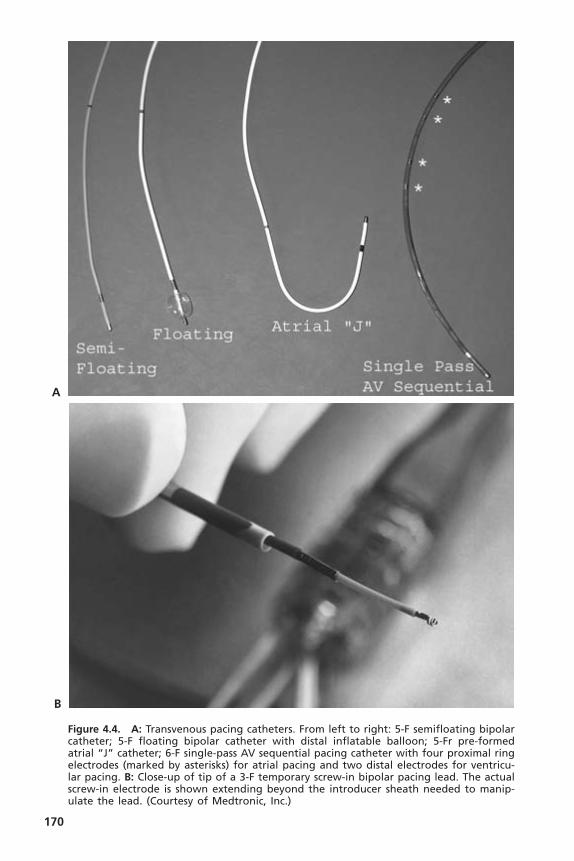
170
Figure 4.4. A: Transvenous pacing catheters. From left to right: 5-F semifloating bipolarcatheter; 5-F floating bipolar catheter with distal inflatable balloon; 5-Fr pre-formedatrial “J” catheter; 6-F single-pass AV sequential pacing catheter with four proximal ringelectrodes (marked by asterisks) for atrial pacing and two distal electrodes for ventricu-lar pacing. B: Close-up of tip of a 3-F temporary screw-in bipolar pacing lead. The actualscrew-in electrode is shown extending beyond the introducer sheath needed to manip-ulate the lead. (Courtesy of Medtronic, Inc.)
A
B

emergency situations.The external jugular and brachial routes are too circuitousto negotiate without fluoroscopy.The cephalic vein is frequently impassable evenwith fluoroscopy due to its acute junction with the axillary vein. Catheter sta-bility is maximized by use of the internal jugular or subclavian routes; it is mostproblematic with peripheral sites, especially brachial, because of movement of the extremities.The peripheral routes do, however, permit greatest control ofbleeding complications and avoid pneumothorax and inadvertent puncture ofthe carotid or subclavian arteries. Femoral venous pacing carries the greatestrisks of thrombosis, phlebitis, and infection, thus necessitating site changes every24 hours.Temporary pacing for extended periods is best tolerated and least com-plicated by using the internal jugular or subclavian routes; however, subclavianaccess may preclude immediate use of this vein for permanent pacing if it isneeded.
Once venous access is obtained, the catheter may be directed to the desiredintracardiac position by electrocardiographic, echocardiographic, or, ideally, flu-oroscopic guidance. Optimal pacing thresholds and lead stability are usuallyachieved in the right ventricular apex and right atrial appendage. An externaldefibrillator should always be present during catheter manipulation. For place-ment in the right ventricular apex, non-floating catheters usually require for-mation and rotation of a loop in the atrium under fluoroscopy but may advance
TEMPORARY CARDIAC PACING
171
Figure 4.5. Pacing pulmonary artery pressure monitoring catheters. Left: Ventricularpacing pulmonary artery catheter using a 3-F wire electrode (arrow) deployed into theright ventricle through a port in the body of the catheter. Right: AV sequential pacingpulmonary artery catheter with three proximal atrial ring electrodes and two distal ven-tricular ring electrodes. The electrodes are highlighted by the arrowheads.
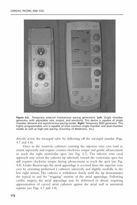
directly across the tricuspid valve by deflecting off the tricuspid annulus (Figs.4.7 and 4.8).
Once in the ventricle, catheters coursing the superior vena cava tend toorient superiorly and require counter-clockwise torque and gentle advancementto reach the right ventricular apex (see Fig. 4.7). The inferior vena cavalapproach may orient the catheter tip inferiorly toward the ventricular apex butstill requires clockwise torque during advancement to reach the apex (see Fig.4.8). Under fluoroscopy, the atrial appendage is accessed from the superior venacava by orienting preformed J catheters anteriorly and slightly medially in thelow right atrium. The catheter is withdrawn slowly until the tip demonstratesthe typical to and fro “wagging” motion of the atrial appendage. Followingcardiac surgery, the atrial appendage may be deformed or absent, requiringapproximation of curved atrial catheters against the atrial wall or interatrialseptum (see Figs. 4.7 and 4.8).
CARDIAC PACING AND ICDS
172
Figure 4.6. Temporary external transvenous pacing generators. Left: Single chambergenerator with adjustable rate, output, and sensitivity. This device is capable of singlechamber demand and asynchronous pacing modes. Right: Temporary DDD generator. Thishighly programmable unit is capable of most common single-chamber and dual-chambermodes as well as high-rate pacing. (Courtesy of Medtronic, Inc.)

TEMPORARY CARDIAC PACING
173
Figure 4.7. Techniques for right ventricular catheter placement from the superior venacava under fluoroscopic guidance. A: Catheter advanced to the low right atrium. B: Further advancement produces a loop or bend in the distal catheter, which is thenrotated medially. C: Alternatively, catheter in low right atrium deflects off tricuspidannulus directly into the right ventricle. D: Superior orientation of the catheter tip in theventricle requires counterclockwise torque during advancement to reach the apex. E: Final catheter position in the right ventricular apex. Catheter position in (B) may besuitable for atrial pacing.

CARDIAC PACING AND ICDS
174
Figure 4.8. Techniques for right ventricular catheter placement from the inferior venacava under fluoroscopic guidance. A: Catheter is advanced to the hepatic vein. B: Cathetertip engages proximal hepatic vein and is advanced further, forming a bend in thecatheter. C: The bend in the distal catheter is then rotated medially. D: Alternatively, thecatheter is advanced to the high medial right atrium. E: With advancement, a bend isformed in the catheter, which is then quickly withdrawn or “snapped” back to the levelof the tricuspid orifice. F: After crossing the tricuspid valve, the catheter is advanced withgentle clockwise torque to reach the apex. G: Final catheter position in the right ven-tricular apex. Catheter positions in (C) and (D) can be used for atrial pacing.

TEMPORARY CARDIAC PACING
175
When fluoroscopy is unavailable or impractical, electrocardiographic guid-ance is possible using flow-directed balloon-tipped catheters or semirigidcatheters. While advancing these leads, the distal electrode is connected to leadV1 of a standard ECG recorder. Balloon-tipped catheters are inflated in thecentral circulation.The catheter location is known from the characteristic unipo-lar electrograms recorded in each chamber (Fig. 4.9). Balloon-tipped cathetersare deflated upon entry into the ventricle to avoid displacement into the pul-monary artery. Large ventricular electrograms (≥6mV) with ST segment eleva-tion (injury pattern) signal contact with ventricular endocardium.There appearsto be no correlation between the magnitude of ST (or PR) segment elevationand pacing threshold, however.24 Echocardiographic guidance of catheter posi-tion is possible by filling the balloon of flow-directed catheters with echogenicfluid.25 In asystole, a semi-floating catheter is advanced during asynchronouspacing at maximal output until ventricular capture is documented by ECGmonitoring or palpation of a pulse. Flow-directed catheters provide the short-est insertion times.26
Once positioned, the electrodes are connected to the pacing generator; forbipolar pacing, the distal pole serves as the cathode (negative pole), and theproximal pole serves as the anode (positive pole). During unipolar pacing, catho-dal intracardiac stimulation reduces thresholds and pacing-related arrhythmiccomplications.27 The anodal (positive) pole of the generator is secured to a sub-cutaneous wire electrode or surface patch electrode with surface area ≥50mm2
to reduce thresholds. During emergency situations, pacing is initiated asynchro-nously, at maximal outputs. Following capture, current output is reduced untilloss of capture defines the pacing threshold. During non-emergency situations,pacing is begun at low outputs in the demand mode at rates slightly above (10ppm) the intrinsic heart rate. Current is increased until capture is achieved.Optimal ventricular and atrial pacing thresholds are less than 1.0mA. Pacemakeroutput is maintained at three to five times threshold to compensate for subse-quent threshold elevations due to inflammation and edema at the electrode-tissue interface, physiologic alterations, or pharmacologic interventions.
Sensing threshold in the demand mode is determined by setting the pace-maker rate below the intrinsic heart rate, then reducing sensitivity (increasingthe value of the millivolt scale) until pacing output occurs. Sensing thresholdsshould be greater than 6mV and 1mV for the ventricle and atrium, respec-tively. Sensitivity is maintained at 25% to 50% of the sensing threshold.AV inter-vals between 100 and 200 milliseconds are usually optimal during AV sequentialpacing. Small changes in the AV interval can significantly influence hemody-namics in some patients.
After initiation of ventricular pacing, the position of the catheter shouldbe confirmed by anteroposterior and lateral chest radiograph and electrocardio-graphy. On the anteroposterior chest radiograph, a catheter tip in the right ven-tricular apex should cross to the left of the spine near the lateral cardiac borderand point slightly inferiorly. On lateral projections, the catheter tip should bedirected anteriorly only a few centimeters posterior to the sternum. Even with

CARDIAC PACING AND ICDS
176
Figure 4.9. Unipolar electrograms obtained from the distal electrode of a temporarypacing catheter. Note the marked ST segment elevation with right ventricular endocar-dial contact and predominantly positive ventricular electrogram morphologies with thepulmonary artery and coronary sinus electrograms. a = atrial electrogram; v = ventricu-lar electrogram; SVC = superior vena cava; RA = right atrium; IVC = inferior vena cava;CS = coronary sinus; Mid RV = mid-right ventricular cavity; RV Contact = contact withright ventricular endocardium; RVOT = right ventricular outflow tract; MPA = main pul-monary artery.
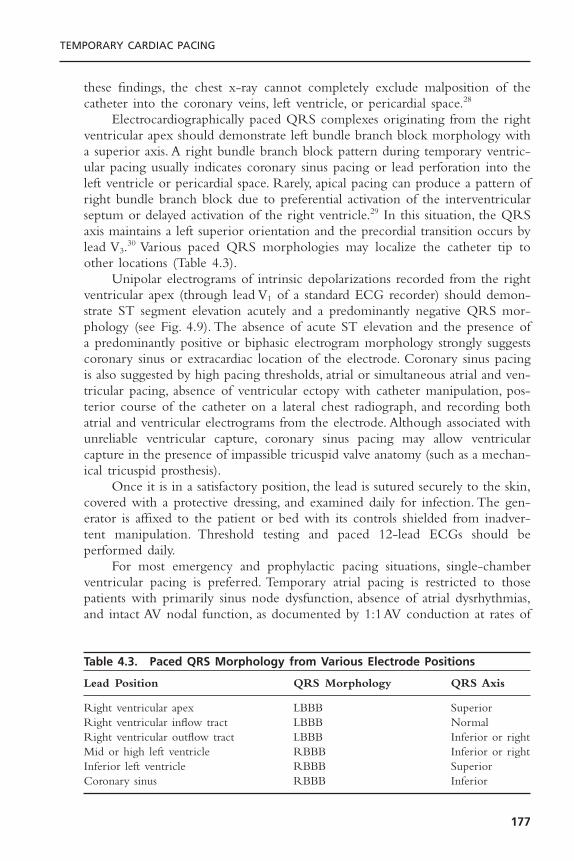
these findings, the chest x-ray cannot completely exclude malposition of thecatheter into the coronary veins, left ventricle, or pericardial space.28
Electrocardiographically paced QRS complexes originating from the rightventricular apex should demonstrate left bundle branch block morphology witha superior axis. A right bundle branch block pattern during temporary ventric-ular pacing usually indicates coronary sinus pacing or lead perforation into theleft ventricle or pericardial space. Rarely, apical pacing can produce a pattern ofright bundle branch block due to preferential activation of the interventricularseptum or delayed activation of the right ventricle.29 In this situation, the QRSaxis maintains a left superior orientation and the precordial transition occurs bylead V3.30 Various paced QRS morphologies may localize the catheter tip toother locations (Table 4.3).
Unipolar electrograms of intrinsic depolarizations recorded from the rightventricular apex (through lead V1 of a standard ECG recorder) should demon-strate ST segment elevation acutely and a predominantly negative QRS mor-phology (see Fig. 4.9). The absence of acute ST elevation and the presence ofa predominantly positive or biphasic electrogram morphology strongly suggestscoronary sinus or extracardiac location of the electrode. Coronary sinus pacingis also suggested by high pacing thresholds, atrial or simultaneous atrial and ven-tricular pacing, absence of ventricular ectopy with catheter manipulation, pos-terior course of the catheter on a lateral chest radiograph, and recording bothatrial and ventricular electrograms from the electrode. Although associated withunreliable ventricular capture, coronary sinus pacing may allow ventricularcapture in the presence of impassible tricuspid valve anatomy (such as a mechan-ical tricuspid prosthesis).
Once it is in a satisfactory position, the lead is sutured securely to the skin,covered with a protective dressing, and examined daily for infection. The gen-erator is affixed to the patient or bed with its controls shielded from inadver-tent manipulation. Threshold testing and paced 12-lead ECGs should beperformed daily.
For most emergency and prophylactic pacing situations, single-chamberventricular pacing is preferred. Temporary atrial pacing is restricted to thosepatients with primarily sinus node dysfunction, absence of atrial dysrhythmias,and intact AV nodal function, as documented by 1:1AV conduction at rates of
TEMPORARY CARDIAC PACING
177
Table 4.3. Paced QRS Morphology from Various Electrode Positions
Lead Position QRS Morphology QRS Axis
Right ventricular apex LBBB SuperiorRight ventricular inflow tract LBBB NormalRight ventricular outflow tract LBBB Inferior or rightMid or high left ventricle RBBB Inferior or rightInferior left ventricle RBBB SuperiorCoronary sinus RBBB Inferior
125ppm. The instability of atrial leads and unpredictable effects of autonomictone and ischemia on AV nodal conduction frequently preclude its use.
Although patients without underlying cardiac disease usually demonstratesimilar hemodynamic responses to atrial and ventricular pacing, the maintenanceof AV synchrony through atrial or dual-chamber pacing is beneficial in patientswith left ventricular systolic and/or diastolic dysfunction.31,32 In these patients, AVsequential pacing may augment cardiac output by 20% to 30% over ventricularpacing alone, while also maintaining higher systemic arterial pressures, lower meanleft atrial pressures, lower pulmonary artery pressures, and enhanced ventricularend-diastolic filling. Patients with acute myocardial infarction (especially right ven-tricular infarction), hypertensive heart disease, hypertrophic or dilated cardiomy-opathies, aortic stenosis, or recent cardiac surgery are known to benefit from AVsequential pacing.33 AV sequential pacing should also be considered in any patientwho has inadequate hemodynamic responses to ventricular pacing alone (forexample, retrograde VA conduction producing pacemaker syndrome).
Initiating and sustaining myocardial capture depends on obtaining a stablecatheter position, the viability of the paced myocardial tissue, and the electricalintegrity of the pacing system. With fluoroscopy, a satisfactory catheter positionshould be obtainable in virtually all patients. The reported incidence of ven-tricular capture without fluoroscopy using flow-directed or semi-floatingcatheters ranges from 30% to 90%.34,35 Capture is least likely during emergencysituations, especially during asystole, without fluoroscopy.34 Catheter coiling inthe right atrium poses the most frequent obstacle to ventricular access and maybe minimized by using the right internal jugular vein approach, using flow-directed catheters, or by advancing preformed J catheters from subclavianapproaches.36 These catheters have a tendency to prolapse into the ventriclewhen advanced beyond the typical atrial position.
Ventricular capture is adversely affected by hypoxia, myocardial ischemia,acidosis, alkalosis, marked hyperglycemia, and hypercapnia. In emergency situa-tions, electrical capture is least likely in the setting of ventricular asystole, prob-ably as a reflection of profound underlying myocardial dysfunction and/or severemetabolic derangement.34 Electrode contact with previously infarcted or fibroticmyocardium may also prevent capture. Pharmacologic interventions such asadministration of type Ia and Ic antiarrhythmics, hypertonic saline, glucose andinsulin, and mineralocorticoids may also increase ventricular capture thresholdsby up to 60%.37 Conversely, thresholds may be decreased by epinephrine,ephedrine, glucocorticoids, and hyperkalemia.37 Isoproterenol may initiallydecrease and subsequently increase the threshold by 20% to 80%.37 Electrolyteeffects tend to be transient. Digitalis, calcium gluconate, morphine sulfate, lido-caine, and atropine have minimal effects on ventricular thresholds. Ventricularthresholds may rise by 40% during sleep and, conversely, may decrease withactivity.38 Lead fractures, unstable electrical connections, generator failure, andbattery depletion may also preclude myocardial capture.
After successful implementation, malfunction of the pacing system mani-festing as inconsistent pacing or sensing may occur in 14% to 43% of
CARDIAC PACING AND ICDS
178
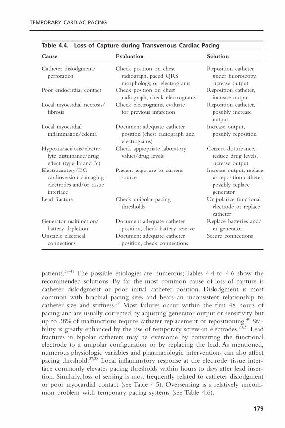
patients.39–41 The possible etiologies are numerous; Tables 4.4 to 4.6 show therecommended solutions. By far the most common cause of loss of capture iscatheter dislodgment or poor initial catheter position. Dislodgment is mostcommon with brachial pacing sites and bears an inconsistent relationship tocatheter size and stiffness.39 Most failures occur within the first 48 hours ofpacing and are usually corrected by adjusting generator output or sensitivity butup to 38% of malfunctions require catheter replacement or repositioning.40 Sta-bility is greatly enhanced by the use of temporary screw-in electrodes.20,21 Leadfractures in bipolar catheters may be overcome by converting the functionalelectrode to a unipolar configuration or by replacing the lead. As mentioned,numerous physiologic variables and pharmacologic interventions can also affectpacing threshold.37,38 Local inflammatory response at the electrode–tissue inter-face commonly elevates pacing thresholds within hours to days after lead inser-tion. Similarly, loss of sensing is most frequently related to catheter dislodgmentor poor myocardial contact (see Table 4.5). Oversensing is a relatively uncom-mon problem with temporary pacing systems (see Table 4.6).
TEMPORARY CARDIAC PACING
179
Table 4.4. Loss of Capture during Transvenous Cardiac Pacing
Cause Evaluation Solution
Catheter dislodgment/ Check position on chest Reposition catheter perforation radiograph, paced QRS under fluoroscopy,
morphology, or electrograms increase outputPoor endocardial contact Check position on chest Reposition catheter,
radiograph, check electrograms increase outputLocal myocardial necrosis/ Check electrograms, evaluate Reposition catheter,
fibrosis for previous infarction possibly increase output
Local myocardial Document adequate catheter Increase output,inflammation/edema position (chest radiograph and possibly reposition
electrograms)Hypoxia/acidosis/electro- Check appropriate laboratory Correct disturbance,
lyte disturbance/drug values/drug levels reduce drug levels,effect (type Ia and Ic) increase output
Electrocautery/DC Recent exposure to current Increase output, replacecardioversion damaging source or reposition catheter,electrodes and/or tissue possibly replace interface generator
Lead fracture Check unipolar pacing Unipolarize functional thresholds electrode or replace
catheterGenerator malfunction/ Document adequate catheter Replace batteries and/
battery depletion position, check battery reserve or generatorUnstable electrical Document adequate catheter Secure connections
connections position, check connections
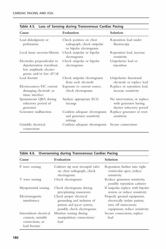
CARDIAC PACING AND ICDS
180
Table 4.5. Loss of Sensing during Transvenous Cardiac Pacing
Cause Evaluation Solution
Lead dislodgment or Check position on chest Reposition lead underperforation radiograph, check unipolar fluoroscopy
or bipolar electrogramsLocal tissue necrosis/fibrosis Check unipolar or bipolar Reposition lead, increase
electrograms sensitivityElectrodes perpendicular to Check unipolar or bipolar Unipolarize lead or
depolarization wavefront, electrograms repositionlow amplitude electro-grams, and/or low dV/dt
Lead fracture Check unipolar electrograms Unipolarize functionalfrom each electrode electrode or replace lead
Electrocautery/DC current Exposure to current source, Replace or reposition lead,damaging electrode or check electrograms increase sensitivitytissue interface
Spontaneous QRS during Analyze appropriate ECG No intervention, or replacerefractory period of tracings with generator having generator shorter refractory period
Generator malfunction Confirm adequate electrograms Replace generator or resetand generator sensitivity sensitivitysettings
Unstable electrical Confirm adequate electrograms Secure connectionsconnections
Table 4.6. Oversensing during Transvenous Cardiac Pacing
Cause Evaluation Solution
P wave sensing Catheter tip near tricuspid valve Reposition further into righton chest radiograph, check ventricular apex, reduceelectrograms sensitivity
T wave sensing Check electrograms Reduce generator sensitivity,possibly reposition catheter
Myopotential sensing Check electrograms during If unipolar, replace with bipolarprecipitating maneuvers system or reduce sensitivity
Electromagnetic Check proper electrical Properly ground equipment,interference grounding and isolation of electrically isolate patient,
patient and pacer system, turn off unnecessarypossibly check electrograms equipment, reduce sensitivity
Intermittent electrical Monitor sensing during Secure connections, replace contacts, unstable manipulation connections/ leadconnections, or leadlead fracture
The complications of transvenous pacing are related to acquisition ofvenous access, intravascular catheter manipulation, and maintenance of anintravascular foreign body. In large series, the reported incidence of clinical com-plications ranges from virtually zero for prophylactic pacemaker insertion in thecatheterization laboratory42 to 20% of cases in coronary intensive care units.40
Complications tend to be more common with brachial or femoral pacing sites.Arterial trauma, air embolism, or pneumothorax may complicate 1% to 2% ofinsertions.43 Significant bleeding may be seen in 4% of patients.40
One of the most common complications of temporary pacing is the induc-tion of ventricular tachycardia or fibrillation.44 Non-sustained ventricular tachy-cardia is most common during catheter manipulation (3% to 10% incidence)and is usually terminated by withdrawal of the catheter.45,46 Ventricular tach-yarrhythmias are more common in the setting of myocardial ischemia, acuteinfarction, hypoxia, general anesthesia, vagal stimulation, drug toxicity, and catecholamine administration and during coronary artery catheterization.47,48
Ventricular fibrillation may complicate up to 14% of acute myocardial infarc-tions requiring temporary pacemaker insertion.48 Supraventricular tachycardiasmay result from catheter manipulation within the atrium.
Myocardial perforation may complicate temporary pacing in 2% to 20% ofcases and is probably underdiagnosed clinically.49,50 Perforation is more commonwith brachial or femoral catheters. Immobilization of the extremities is recom-mended to prevent excessive motion of the catheter. Diagnostic signs and symp-toms of myocardial perforation are listed in Table 4.7. Loss of pacing or sensing,changes in paced QRS morphology, and diaphragmatic or skeletal muscle pacingare the most common manifestations; however, perforation to intracardiac andextracardiac locations can be clinically silent.50 Penetration into the myocardiummay occur in up to 30% of patients and is suggested by ventricular arrhythmiaswith the same morphology as paced complexes.43 Perforation of the interven-tricular septum is usually hemodynamically inconsequential; however, extracar-diac migration of the catheter can produce pericardial tamponade inapproximately 1% of perforations.43 Pericarditis may be seen in 5% of patientswith perforated temporary pacing catheters.43
In the absence of hemodynamically significant pericardial effusion, myocar-dial perforation is managed by catheter withdrawal until effective capture isrestored. Careful patient monitoring follows. Unipolar electrograms recordedfrom the catheter tip will demonstrate a pathognomonic transition from R waveto S wave morphology with ST elevation upon withdrawal from extracardiacto intracardiac locations (Fig. 4.10), thereby confirming the diagnosis.51
Thromboembolic events from temporary pacing appear to be more fre-quent than are clinically recognized. Venograms or ultrasound in patients withfemoral pacing catheters reveal evidence of femoral venous thrombosis in up to39% of the patients despite their receiving subcutaneous or systemic heparin.52,53
Of the patients with thrombosis, 60% may have evidence of pulmonary embolion ventilation perfusion scans.52 Thrombosis is rarely suspected clinically. Theincidence of thrombosis with other pacing sites has not been systematically
TEMPORARY CARDIAC PACING
181
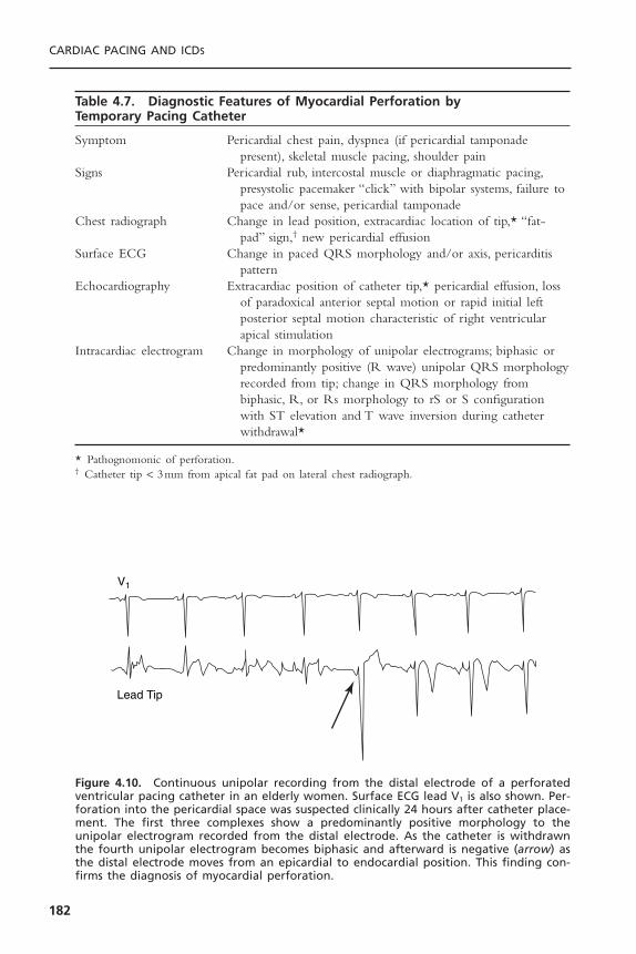
CARDIAC PACING AND ICDS
182
V1
Lead Tip
Figure 4.10. Continuous unipolar recording from the distal electrode of a perforatedventricular pacing catheter in an elderly women. Surface ECG lead V1 is also shown. Per-foration into the pericardial space was suspected clinically 24 hours after catheter place-ment. The first three complexes show a predominantly positive morphology to theunipolar electrogram recorded from the distal electrode. As the catheter is withdrawnthe fourth unipolar electrogram becomes biphasic and afterward is negative (arrow) asthe distal electrode moves from an epicardial to endocardial position. This finding con-firms the diagnosis of myocardial perforation.
Table 4.7. Diagnostic Features of Myocardial Perforation by Temporary Pacing Catheter
Symptom Pericardial chest pain, dyspnea (if pericardial tamponadepresent), skeletal muscle pacing, shoulder pain
Signs Pericardial rub, intercostal muscle or diaphragmatic pacing,presystolic pacemaker “click” with bipolar systems, failure topace and/or sense, pericardial tamponade
Chest radiograph Change in lead position, extracardiac location of tip,* “fat-pad” sign,† new pericardial effusion
Surface ECG Change in paced QRS morphology and/or axis, pericarditispattern
Echocardiography Extracardiac position of catheter tip,* pericardial effusion, lossof paradoxical anterior septal motion or rapid initial leftposterior septal motion characteristic of right ventricularapical stimulation
Intracardiac electrogram Change in morphology of unipolar electrograms; biphasic orpredominantly positive (R wave) unipolar QRS morphologyrecorded from tip; change in QRS morphology frombiphasic, R, or Rs morphology to rS or S configurationwith ST elevation and T wave inversion during catheterwithdrawal*
* Pathognomonic of perforation.† Catheter tip < 3mm from apical fat pad on lateral chest radiograph.
studied. Systemic anticoagulation with femoral pacing may reduce but does noteliminate venous thrombosis.53
Clinical infection or phlebitis complicates temporary pacing in 3% to 5% ofpatients and is most common with femoral sites.40 Bacteremia has been demon-strated in 50% of patients by the third day of temporary pacing.43 Sepsis is muchless frequent, however. In general, pacing sites should be changed every 72 hours.
Other complications include knotting of catheters, induction of rightbundle branch block (1%), and phrenic nerve or diaphragmatic pacing in theabsence of myocardial perforation (10%).43
EPICARDIAL PACINGTransthoracic pacing is possible using temporary pacing wires passively fixed tothe atrial and ventricular epicardium at the time of cardiac surgery or thoracot-omy. The wires, usually paired to each chamber with or without a third sub-cutaneous lead for unipolar pacing. They are exposed through the skin in thesubxiphoid region. Bipolar leads are also available. The wires should be appro-priately marked as atrial or ventricular leads. If uncertain, the origin of the leadmay be confirmed by pacing, timing unipolar electrograms from the lead withsurface ECG signals, or chest radiograph examination. These leads are used ina similar fashion to transvenous leads; however, pacing and sensing thresholdstend to deteriorate progressively within days of implantation. Pacing thresholdsin both chambers are elevated by the fourth postoperative day and sensingthresholds are lower on the second postoperative day (Fig. 4.11).54 The use ofbipolar electrodes may minimize sensing and pacing failures, especially for atrialpacing.55 Reversal of bipolar lead polarity or unipolarization of the leads maycircumvent high thresholds.Temporary biventricular pacing may improve hemo-dynamics in some patients following cardiac surgery.56
TRANSESOPHAGEAL PACINGThe anatomic proximity of the esophagus to the posterior left atrium makestransesophageal atrial pacing possible in nearly all patients.The technique is rel-atively noninvasive and virtually free of serious complications. Furthermore, thetechnique requires minimal training to perform successfully. However, ventricu-lar capture is inconsistent or often intolerably painful, which seriously limits thetherapeutic and emergency applications of the technique.Transesophageal pacingis now used primarily to terminate supraventricular arrhythmias in patientsunder general anesthesia or pediatric patients. It has also been used as a substi-tute for pharmacologic provocation in stress testing.57–61
Transesophageal pacing uses an intraesophageal electrode positioned inproximity to the heart to deliver stimulating electrical current to the myocar-dial tissue.The necessary equipment includes a specialized bipolar electrode anda transesophageal pulse generator with unique output characteristics (Fig. 4.12).Dedicated transesophageal pacing catheters are 5 to 10F flexible designs for oralor nasal introduction (Fig. 4.13).Theoretically, the optimal interelectrode spacing
TEMPORARY CARDIAC PACING
183
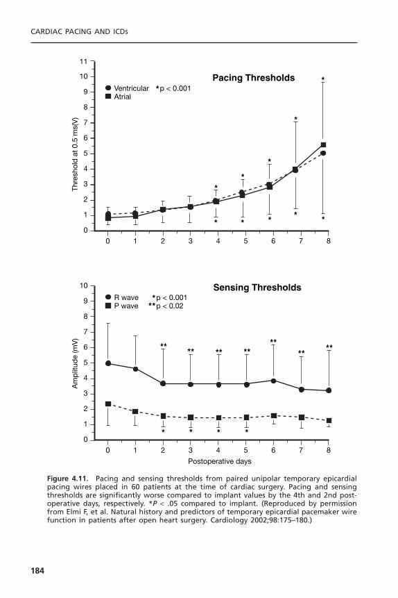
CARDIAC PACING AND ICDS
184
0 1 2 3 4 5 6 7 8
3
4
5
6
7
8
9
10
R wave p < 0.001p < 0.02P wave
Am
plit
ude
(mV
)
Postoperative days
Sensing Thresholds
2
1
0
**
***
* * * *
** ** ****
****
0 1 2 3 4 5 6 7 8
3
4
5
6
7
8
9
10
11
Ventricular p < 0.001Atrial
Thre
shol
d a
t 0.
5 m
s(V
)Pacing Thresholds
2
1
0
*
*
*
* * * *
*
*
**
Figure 4.11. Pacing and sensing thresholds from paired unipolar temporary epicardialpacing wires placed in 60 patients at the time of cardiac surgery. Pacing and sensingthresholds are significantly worse compared to implant values by the 4th and 2nd post-operative days, respectively. *P < .05 compared to implant. (Reproduced by permissionfrom Elmi F, et al. Natural history and predictors of temporary epicardial pacemaker wirefunction in patients after open heart surgery. Cardiology 2002;98:175–180.)

for bipolar transesophageal pacing is directly proportional to 1.4 times the dis-tance separating the excitable tissue from the midpoint between the pacing elec-trodes.62 Fluoroscopic and anatomic studies reveal that the minimum distancefrom the esophagus to the left atrium in humans is 0.5 to 1.5cm, regardless ofleft atrial size.63 Clinically, spacings of 1.0 to 3.0cm yield comparable atrialpacing thresholds.64–66
Transesophageal pacing generators must provide up to 25 to 30mA ofcurrent output into high transesophageal impedances of 700 to 2600ohms.64
High-voltage outputs of 40 to 75V are thereby mandatory for these devices.Stimulation pulse width should be up to 10 to 20 milliseconds to minimizepacing thresholds.62,67 The short pulse width (1 to 2 milliseconds) and low volt-
TEMPORARY CARDIAC PACING
185
Figure 4.12. Specialized esophageal pacing generator and preamplifier for recordingelectrograms from the esophageal electrodes. (Courtesy of Cardiocommand, Inc.)
Figure 4.13. Specialized flexible 10-F (top) and 5-F (bottom) transesophageal pacingcatheters. (Courtesy of Cardiocommand, Inc.)
ages (12 to 15V) provided by temporary transvenous pacing generators are notadequate for transesophageal pacing.
To initiate transesophageal pacing, the electrode is introduced orally ornasally, then advanced distally through the esophagus into proximity with theleft atrium. Aspiration precautions should be observed during esophageal intu-bation, and other esophageal catheters should be removed if possible. Topicalanesthesia to the nares and pharynx is recommended. The optimal esophagealsite for atrial pacing is then identified by the esophageal electrode positionrecording the largest peak-to-peak atrial electrogram (Fig. 4.14).67 Unipolar orbipolar electrograms may be used by connecting an electrode pole to lead V1
(unipolar) or to each arm lead (bipolar) of a standard ECG recorder.After intro-duction to 30 to 40cm from the teeth or nares, the lead is moved proximallyand distally until the largest atrial electrogram is recorded.68 This site averages35 to 40cm from the teeth or nares in most adult studies.66,67 The most favor-able electrode position for transesophageal ventricular pacing is less well definedbut appears to lie 2 to 4cm distal to the best site for atrial pacing.69 A ven-tricular electrogram should be recorded from sites of attempted ventricularpacing; otherwise, the ventricular electrogram amplitude is not helpful.
Once positioned, the electrodes are connected to the transesophagealpacing generator. Capture thresholds are reduced by cathodal (negative) stimu-lation through the proximal electrode in bipolar systems.66 Ventricular capturemust be excluded before attempting rapid atrial pacing. Virtually all patientsexperience at least a mild thoracic burning sensation with effective currentoutputs. Once capture is achieved, the lead is taped securely to the patient’s noseor chin.
In most large series, the incidence of atrial capture with transesophagealpacing equals or approaches 100% with mean current thresholds of 8 to 14mA.62,64,70 Atrial capture thresholds are not influenced by age, height, weight,body surface area, left atrial size, previous coronary bypass surgery, presence ofstructural heart disease, or size of recorded atrial electrograms in most studies.71,72
Thresholds greater than 15mA are frequently associated with increased patientdiscomfort.
Ventricular capture using transesophageal pacing is unreliable. Using con-ventional transesophageal electrodes and pacing generators, ventricular captureis successful only in 3% to 60% of patients.70–73 Because the stimulating currentdensity declines exponentially with distance from the bipolar current source, theventricle, typically approximately 3cm from the esophagus, receives only 20%of the current density achieved at the left atrium during transesophagealpacing.62,71
Serious complications of transesophageal pacing are limited to inductionof ventricular tachyarrhythmias during rapid atrial pacing in three patients.71,74
No long-term pacing complications have been reported. Virtually all patientsexperience mild chest or back pain, or a sensation of burning or indigestionduring pacing at outputs less than 15mA. Endoscopy following transesophagealpacing may reveal focal pressure necrosis typical of any indwelling esophageal
CARDIAC PACING AND ICDS
186

catheter in up to 11% of patients.71 No significant esophageal trauma had beenreported in humans despite pacing up to 60 hours.75 Aspiration is a potentialcomplication of any esophageal intubation procedure. Diaphragmatic or phrenicnerve pacing may occur in 1% to 8% of patients, especially with distal esophagealcatheter positions.70,76 Coughing may be induced with proximal catheter posi-tions due to tracheal stimulation, and brachial plexus stimulation has beenreported in infants.77
TEMPORARY CARDIAC PACING
187
Figure 4.14. Illustration depicting transesophageal cardiac electrograms obtained fromvarious catheter insertion depths in a 6-year-old child. A = atrial electrogram; V = ven-tricular electrogram. Minimal transesophageal atrial pacing thresholds correspond toelectrode positions recording the atrial electrograms of largest amplitude. (Reproducedby permission from the American Heart Association from Benson DW. Transesophagealelectrocardiography and cardiac pacing: state of the art. Circulation 1987;75 (suppl3):86–90.)
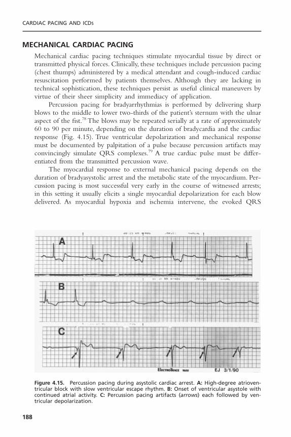
MECHANICAL CARDIAC PACINGMechanical cardiac pacing techniques stimulate myocardial tissue by direct ortransmitted physical forces. Clinically, these techniques include percussion pacing(chest thumps) administered by a medical attendant and cough-induced cardiacresuscitation performed by patients themselves. Although they are lacking intechnical sophistication, these techniques persist as useful clinical maneuvers byvirtue of their sheer simplicity and immediacy of application.
Percussion pacing for bradyarrhythmias is performed by delivering sharpblows to the middle to lower two-thirds of the patient’s sternum with the ulnaraspect of the fist.78 The blows may be repeated serially at a rate of approximately60 to 90 per minute, depending on the duration of bradycardia and the cardiacresponse (Fig. 4.15). True ventricular depolarization and mechanical responsemust be documented by palpitation of a pulse because percussion artifacts mayconvincingly simulate QRS complexes.79 A true cardiac pulse must be differ-entiated from the transmitted percussion wave.
The myocardial response to external mechanical pacing depends on theduration of bradyasystolic arrest and the metabolic state of the myocardium. Per-cussion pacing is most successful very early in the course of witnessed arrests;in this setting it usually elicits a single myocardial depolarization for each blowdelivered. As myocardial hypoxia and ischemia intervene, the evoked QRS
CARDIAC PACING AND ICDS
188
Figure 4.15. Percussion pacing during asystolic cardiac arrest. A: High-degree atrioven-tricular block with slow ventricular escape rhythm. B: Onset of ventricular asystole withcontinued atrial activity. C: Percussion pacing artifacts (arrows) each followed by ven-tricular depolarization.

complexes widen and occur in salvos or extended runs. Further metabolic com-promise is associated with loss of QRS voltage, appearance of injury patterns,induction of ventricular fibrillation, and, eventually, failure of response.80 If per-cussion pacing initially fails, repeated attempts after the administration of chestcompressions and inotropic agents may be successful.81
Percussion pacing has sustained patients for up to 60 minutes as the solemechanism of cardiac stimulation.80 Single and serial chest blows have also beenused to terminate ventricular tachycardia in humans.82
Cough-induced cardiac resuscitation is another mechanical means of gen-erating cardiac output.83,84 A forceful cough can generate up to 25 J of kineticenergy within the chest cavity.84 It is unclear whether this energy inducesmyocardial contraction or whether cardiac output is produced by compressionof intrathoracic structures with up to 250 to 450mmHg of pressure generatedby the cough.84
To perform this maneuver, the conscious patient is instructed to coughforcefully every 1 to 3 seconds until an effective native rhythm returns or defin-itive treatment is administered. Paroxysms of coughing are ineffective. Clinically,cough-induced resuscitation has maintained aortic systolic blood pressures above130mmHg during ventricular fibrillation as opposed to only 60mmHg duringexternal chest compressions in the same patients.83 Patients performing cough-induced resuscitation during ventricular fibrillation have remained conscious forup to 92 seconds.83 The technique has the disadvantage of requiring a consciouspatient who is able to immediately generate effective coughs within seconds ofthe onset of bradycardia.
SELECTION OF THE OPTIMAL TEMPORARY PACING TECHNIQUEThe urgency to initiate temporary cardiac pacing is the foremost considerationin selecting among the available techniques. For prophylactic and nonemergencyapplications, the duration of pacing, comfort of the patient, and desire to avoidspecific complications also become significant. In emergency situations ofbradyasystolic arrest, delayed recovery of an effective cardiac rhythm beyond 5minutes virtually precludes successful resuscitation. In these situations, rapid ini-tiation of ventricular pacing is paramount to other considerations.Although trans-venous pacing has traditionally served as the mainstay of emergency temporarypacing, the significant time and operator skill needed to implement the tech-nique are less than ideal.Transcutaneous pacing has provided an extremely rapid,simple, and noninvasive alternative to emergency transvenous pacing. The inci-dence of ventricular capture during arrest is quite variable for both techniques.
Given the narrow therapeutic time constraints in bradyasystolic arrest, oneshould proceed with the mode of pacing that will effect ventricular pacing mostrapidly. Attempts at transcutaneous pacing neither interrupt nor impede perfor-mance of cardiopulmonary resuscitation (CPR), and it is usually feasible toattempt transcutaneous pacing while preparations are made for more invasivetechniques.
TEMPORARY CARDIAC PACING
189

CA
RD
IAC
PAC
ING
AN
D IC
DS
190
Table 4.8. Comparison of Temporary Pacing Techniques
Transvenous Transcutaneous Transesophageal Epicardial Percussion Cough CPR
Time to initiate 3–10min <1min minutes <1min immediate immediate
Training extensive minimal moderate minimal minimal minimal
Chambers paced atrium and/or ventricle atrium, possibly atrium and/or ventricle noneventricle ventricle ventricle
Emergency use + + - + if wires in + +
Prophylactic use + + - + - -
Prolonged use + - - + - -
Vascular injury + - - - - -
Arrhythmias + - - - + -
Infection + - - - - -
Discomfort - + + - + -
Comments most versatile fast, safe, easy primarily atrial postoperative witnessed brady- cooperative patient, supportsand reliable pacing use only cardic arrest ventricular fibrillation

For prophylactic use, transcutaneous pacing is the method of choice, givenits high efficacy combined with virtual absence of complications. Patient dis-comfort during pacing represents the only disadvantage.Temporary transvenouspacing, although invasive, provides well-tolerated and generally reliable atrialand/or ventricular pacing for extended periods of time. Transesophageal pacingis suitable for elective atrial pacing applications. Patient discomfort is sometimesa problem, but complications are exceptionally rare.Ventricular capture requirespainfully high current outputs, but intraoperative use appears feasible.
Mechanical and cough-induced resuscitation techniques are limited to verybrief applications. Nevertheless, cough-induced resuscitation is an effective andstandard maneuver during asystole induced by coronary angiography. A com-parison of the available temporary pacing techniques is shown in Table 4.8.
REFERENCES1. Falk RH, Ngai STA. External cardiac pacing: influence of electrode placement on
pacing threshold. Crit Care Med 1986;14:931–932.2. Sado DM, Deakin CD, Petley GW, Clewlow F. Comparison of the effects for removal
of chest hair with doing nothing before external defibrillation on transthoracicimpedance. Am J Cardiol 2004;93:98–100.
3. Madsen JK, Pedersen F, Grande P, Meiborn J. Normal myocardial enzymes andnormal echocardiographic findings during noninvasive transcutaneous pacing. PacingClin Electrophysiol 1988;11:1188–1193.
4. Klein LS, Miles WM, Heger JJ, Zipes DP. Transcutaneous pacing: patient tolerance,strength–interval relations and feasibility for programmed electrical stimulation. AmJ Cardiol 1988;62:1126–1129.
5. Zoll PM, Zoll RH, Falk RH, et al. External noninvasive temporary cardiac pacing:clinical trials. Circulation 1985;71:937–944.
6. Falk RH, Ngai STA, Kumanki DJ, Rubinstein JA. Cardiac activation during exter-nal cardiac pacing. Pacing Clin Electrophysiol 1987;10:503–506.
7. Kelly JS, Royster RL, Angert KC, Case LD. Efficacy of noninvasive transcutaneouscardiac pacing in patients undergoing cardiac surgery. Anesth Analg 1989;70:747–751.
8. Luck JC, Grubb BP, Artman SE, et al. Termination of sustained ventricular tachy-cardia by external noninvasive pacing. Am J Cardiol 1988;61:574–577.
9. Hedges JR, Syverud SA, Dalsey WC, et al. Threshold, enzymatic, and pathologicchanges associated with prolonged transcutaneous pacing in a chronic heart blockmodel. J Emerg Med 1989;7:1–4.
10. Feldman MD, Zoll PM, Aroesty JM, et al. Hemodynamic responses to noninvasiveexternal cardiac pacing. Am J Med 1988;84:395–400.
11. Trigano JA, Remond JM, Mourot F, et al. Left ventricular pressure measurementduring noninvasive transcutaneous cardiac pacing. Pacing Clin Electrophysiol1989;12:1717–1719.
12. Murdock DK, Moran JF, Speranza D, et al.Augmentation of cardiac output by exter-nal cardiac pacing: pacemaker-induced CPR. Pacing Clin Electrophysiol 1986;9:127–129.
13. Falk RH, Zoll PM, Zoll RH. Safety and efficacy of noninvasive cardiac pacing: apreliminary report. N Engl J Med 1983;309:1166–1168.
TEMPORARY CARDIAC PACING
191
14. Altamura G, Bianconi L, Boccadamo R, Pistalese M. Treatment of ventricular andsupraventricular tachyarrhythmias by transcutaneous cardiac pacing. Pacing ClinElectrophysiol 1989;12:331–338.
15. Zoll PM. Resuscitation of the heart in ventricular standstill by external electricalstimulation. N Engl J Med 1952;247:768–771.
16. Estes M, Deering TF, Manolis AS, et al. External cardiac programmed stimulationfor noninvasive termination of sustained supraventricular and ventricular tachycar-dia. Am J Cardiol 1989;63:177–183.
17. Beland MJ, Hesslein PS, Rowe RD.Ventricular tachycardia related to transcutaneouspacing. Ann Emerg Med 1988;17:279–281.
18. Voorhees WD III, Foster KS, Geddes LA, Babbs CF. Safety factor for precordialpacing: minimum current thresholds for pacing and for ventricular fibrillation byvulnerable-period stimulation. Pacing Clin Electrophysiol 1984;7:356–360.
19. Francis GS,Williams SV,Achord JL, et al. Clinical competence in insertion of a tem-porary transvenous ventricular pacemaker. J Am Coll Cardiol 1994;23:1254–1257.
20. de Cock CC,Van Campen LC,Visser CA. Usefulness of a new active-fixation leadin transvenous temporary pacing from the femoral approach. PACE 2003;26:849–852.
21. de Cock CC, Van Campen LC, In’t Veld JA, Visser CA. Utility and safety of pro-longed temporary transvenous pacing using and active-fixation lead: Comparisonwith a conventional lead. PACE 2003;26:1245–1248.
22. Simpson C,Yee R, Lee J, et al. Clinical evaluation of a new active fixation tempo-rary cardiac pacing lead. Circulation 1998;98:I-427.
23. Syverud SA, Dalsey WC, Hedges JR, Hanseits ML. Radiologic assessment of trans-venous pacemaker placement during CPR. Ann Emerg Med 1986;15:131–137.
24. Goldberger J, Kruse J, Ehlert FA, Kadish A.Temporary transvenous pacemaker place-ment: what criteria constitute an adequate pacing site? Am Heart J 1993;126:488–493.
25. Kaemmerer H, Kochs M, Hombach V. Ultrasound-guided positioning of temporarypacing catheters and pulmonary artery catheters after echogenic marking. ClinIntensive Care 1993;4:4–7.
26. Lang R, David D, Klein HO, et al. The use of the balloon-tipped floating catheterin temporary transvenous cardiac pacing. Pacing Clin Electrophysiol 1981;4:491–496.
27. Furman S, Hurzeler P, Mehra R. Cardiac pacing and pacemakers. IV. Threshold ofcardiac stimulation. Am Heart J 1977;94:115–124.
28. Gulotta SJ.Transvenous cardiac pacing: techniques for optimal electrode positioningand prevention of coronary sinus placement. Circulation 1970;42:701–718.
29. Castellanos A, Maytin O, Lemberg L, Castillo C. Unusual QRS complexes producedby pacemaker stimuli with special reference to myocardial tunneling and coronarysinus stimulation. Am Heart J 1969;77:732–742.
30. Coman JA, Trohman RG. Incidence and electrocardiographic localization of saferight bundle branch block configuration during permanent ventricular pacing. AmJ Cardiol 1995;76:781–784.
31. Befeler B, Hildner FJ, Javier RP, et al. Cardiovascular dynamics during coronarysinus, right atrial, and right ventricular pacing. Am Heart J 1971;81:372–380.
32. Benchimol A, Ellis JG, Dimond EG. Hemodynamic consequences of atrial and ven-tricular pacing in patients with normal and abnormal hearts. Am J Med1965;39:911–922.
CARDIAC PACING AND ICDS
192
33. Hartzler GO, Maloney JD, Curtis JJ, Barnhorst DA. Hemodynamic benefits of atrio-ventricular sequential pacing after cardiac surgery. Am J Cardiol 1977;40:232–236.
34. Hazard PB, Benton C, Milnor JP. Transvenous cardiac pacing in cardiopulmonaryresuscitation. Crit Care Med 1981;9:666–668.
35. Phillips SJ, Butner AN. Percutaneous transvenous cardiac pacing initiated at bedside:results in 40 cases. J Thorac Cardiovasc Surg 1970;59:855–858.
36. Davis MJE. Emergency ventricular pacing using a J-electrode without fluoroscopy.Med J Aust 1990;152:194.
37. Preston TA, Fletcher RD, Luccesi BR, Judge RD. Changes in myocardial threshold.Physiologic and pharmacologic factors in patients with implanted pacemakers. AmHeart J 1967;74:235–242.
38. Sowton E, Barr I. Physiologic changes in threshold. Ann NY Acad Sci 1969;167:678–685.
39. Krueger SK, Rakes S,Wilkerson J, et al.Temporary pacemaking by general internists.Arch Intern Med 1983;143:1531–1533.
40. Austin JL, Preis LK, Crampton RS, et al. Analysis of pacemaker malfunction andcomplications of temporary pacing in the coronary care unit. Am J Cardiol1982;49:301–306.
41. Lumia FJ, Rios JC. Temporary transvenous pacemaker therapy an analysis of com-plications. Chest 1973;64:604–608.
42. Harvey JR, Wyman RM, McKay RG, Baim DS. Use of balloon flotation pacingcatheters for prophylactic temporary pacing during diagnostic and therapeuticcatheterization procedures. Am J Cardiol 1988;62:941–944.
43. Silver MD, Goldschlager N.Temporary transvenous cardiac pacing in the critical caresetting. Chest 1988;93:607–613.
44. Paulk EA, Hurst JW. Complete heart block in acute myocardial infarction. Am JCardiol 1966;17:695–706.
45. Hynes JK, Holmes DR Jr, Harrison CE. Five-year experience with temporary pace-maker therapy in the coronary care unit. Mayo Clin Proc 1983;58:122–126.
46. Jowett NI,Thompson DR, Pohl JEF.Temporary transvenous cardiac pacing: a year’sexperience in one coronary care unit. Postgrad Med J 1989;65:211–215.
47. Lehmann MH, Cameron A, Kemp HG Jr. Increased risk of ventricular fibrillationassociated with temporary pacemaker use during coronary arteriography. Pacing ClinElectrophysiol 1983;6:923–928.
48. Mooss AN, Ross WB, Esterbrooks DJ, et al. Ventricular fibrillation complicatingpacemaker insertion in acute myocardial infarction. Cath Cardiovasc Diag 1982;8:253–259.
49. Weinstein J, Gnoj J, Mazzara JT, et al.Temporary transvenous pacing via the percu-taneous femoral vein approach. Am Heart J 1973;85:695–705.
50. Nathan DA, Center S, Pina RE, et al. Perforation during indwelling catheter pacing.Circulation 1966;33:128–130.
51. Van Durme JP, Heyndrickx G, Snoeck J, et al. Diagnosis of myocardial perforationby intracardiac electrograms recorded from the indwelling catheter. J Electrocard1973;6:97–102.
52. Nolewajka AJ, Goddard MD, Broun TC.Temporary transvenous pacing and femoralvein thrombosis. Circulation 1980;62:646–650.
53. Sanders P, Farouque O, Ashby DT, Mahar LJ,Young GD. Effects of anticoagulationon the occurrence of deep venous thrombosis associated with temporary transve-nous femoral pacemakers. Am J Cardiol 2001;88:798–801.
TEMPORARY CARDIAC PACING
193

54. Elmi F, Tullo N, Khalighi K. Natural history and predictors of temporary epicardialpacemaker wire function in patients after open heart surgery. Cardiology 2002;98:175–180.
67. Cohen SI, Smith KL. Transfemoral cardiac pacing and phlebitis. Circulation1974;49:1018–1019.
68. Roe BB, Katz HJ. Complete heart block with intractable asystole and recurrent ven-tricular fibrillation with survival. Am J Cardiol 1965;15:401–403.
55. Scherhag A, Gulbins H, Lange R, Saggaw W. Improved reliability of postoperativecardiac pacing by use of bipolar temporary pacing leads. Eur JCPE 1995;5:101–108.
56. Janousek J, Hucin B, Tlaskai T, et al. Resynchronization pacing is a useful adjunctto the management of acute heart failure after surgery for congenital heart defects.Am J Cardiol 2001;88:145–152.
57. Anselmi M, Golia G, Rossi A, et al. Feasibility and safety of transesophageal atrialpacing stress echocardiography in patients with known or suspected coronary arterydisease. Am J Cardiol 2003;92:1384–1388.
58. Hessling G, Brockmeier K, Ulmer HE. Transesophageal electrocardiography andatrial pacing in children. J Electrocardiol 2003;35(suppl):143–149.
59. Romano R, Ciccaglioni A, Rocco A, et al.Transesophageal atrial pacing in the man-agement of re-entry supraventricular tachyarrhythmias occurring during generalanesthesia. Minerva Anesthesiol 2003;68:825–829.
60. Atar S, Nagai T, Cecek B, et al. Pacing stress echocardiography: an alternative topharmacologic stress testing. J Am Coll Cardiol 200;36:1935–1941.
61. Atar S, Nagai T, Cecek B, et al. Transthoracic stress echocardiography with trans-esophageal atrial pacing for bedside evaluation of inducible myocardial ischemia inpatients with new-onset chest pain. Am J Cardiol 2000;86:12–16.
62. Arzbacher R, Jenkins JM. A review of the theoretical and experimantal bases oftransesophageal atrial pacing. J Electrocardiol 2002;35(suppl):137–141.
63. Binkley PF, Bush CA, Kolibash AJ, et al.The anatomic relationship of the esophageallead to the left atrium. Pacing Clin Electrophysiol 1982;5:853–859.
64. Kerr CR, Chung DC,Wickham G, et al. Impedance to transesophageal atrial pacing:significance regarding power sources. Pacing Clin Electrophysiol 1989;12:930–935.
65. Benson DW. Transesophageal electrocardiography and cardiac pacing: state of theart. Circulation 1987;75(suppl 3):86–92.
66. Nishimura M, Katoh T, Hanai S,Watanabe Y. Optimal mode of transesophageal atrialpacing. Am J Cardiol 1986;57:791–796.
67. Benson DW, Sanford M, Dunnigan A, Benditt DG. Transesophageal atrial pacingthreshold: role of interelectrode spacing, pulse width, and catheter insertion depth.Am J Cardiol 1984;53:63–67.
68. Hammill SC, Pritchett ELC. Simplified esophageal electrocardiography using bipolarrecording leads. Ann Intern Med 1981;95:14–18.
69. Andersen HR, Pless P. Transesophageal pacing. Pacing Clin Electrophysiol 1983;6:674–679.
70. Gallagher JJ, Smith WM, Kerr CR, et al. Esophageal pacing: a diagnostic and ther-apeutic tool. Circulation 1982;65:336–341.
71. Dick M, Campbell RM, Jenkins JM. Thresholds for transesophageal atrial pacing.Cath Cardiovasc Diag 1984;10:507–513.
72. Buchanan D, Clements F, Reves JG, et al.Atrial esophageal pacing in patients under-going coronary artery bypass grafting: effect of previous cardiac operations and bodysurface area. Anesth Analg 1988;69:595–598.
CARDIAC PACING AND ICDS
194
73. Lubell DL. Cardiac pacing from the esophagus. Am J Cardiol 1971;27:641–644.74. Favale S, Di Biase M, Rizzo U, et al. Ventricular fibrillation induced by trans-
esophageal atrial pacing in hypertrophic cardiomyopathy. Eur Heart J 1987;8:912–916.
75. Burack B, Furman S.Transesophageal cardiac pacing.Am J Cardiol 1969;23:469–472.76. Backofen JE, Schauble JF, Rogers MC. Transesophageal pacing for bradycardia.
Anesth Analg 1984;61:777–779.77. Benson DW, Dunnigan A, Benditt DG, Schneider SP.Transesophageal cardiac pacing:
history, application, technique. Clin Prog Pacing Electrophysiol 1984;2:360–372.78. Chester WL. Spinal anesthesia, complete heart block and the precordial thump: an
unusual complication and a unique resuscitation. Anesth Analg 1988;69:600–602.79. Skaaland K. Effect of chest pounding: electrocardiographic pattern. Lancet 1972;1:
1121–1122.80. Scherf D, Bornemann C. Thumping of the precordium in ventricular standstill. Am
J Cardiol 1960;5:30–40.81. Iseri LT, Allen BJ, Baron K, Brodsky MA. Fist pacing, a forgotten procedure in
bradysystolic cardiac arrest. Am Heart J 1987;113:1545–1550.82. Margera T, Baldi N, Chersevani D, et al. Chest thump and ventricular tachycardia.
Pacing Clin Electrophysiol 1979;2:69–75.83. Criley JM, Blaufuss AH, Kissel GL. Cough-induced cardiac compression: self-admin-
istered form of cardiopulmonary resuscitation. JAMA 1976;236:1246–1250.84. Wei JY, Greene HL,Weisfeldt ML. Cough-facilitated conversion of ventricular tachy-
cardia. Am J Cardiol 1980;45:174–176.
TEMPORARY CARDIAC PACING
195
196
A permanent pacing system consists of the pacemaker generator and the oneor more leads that connect it to the endocardial or epicardial surface of theheart. Because of the initial mandate for epicardial lead placement, pacemakerimplantation has traditionally been the task of the surgeon. Considerable evo-lution in technique and hardware has occurred over the past three decades,which has greatly simplified the implantation procedure. The introduction ofrelatively simple and safe methods of central venous access has facilitated thealmost universal adoption of transvenous leads, which have proven to be themost reliable means of pacing the heart. Associated with this has been a minia-turization of the power source and circuitry of the generator such that its sub-cutaneous placement has become less demanding even in the very young orelderly.
Compared to the need to formulate optimal programming prescriptionsand interpret complex electrocardiography (ECG)–pacer–patient interactions,the implantation of a modern sophisticated microprocessor based pacemaker maynow be the least arduous aspect of pacing. Reflecting these changes has beenthe increasingly predominant role of the cardiologist, the electrophysiologist par-ticularly, in the implantation process. It would be inappropriate however to giveone the impression that all pacemaker implantation is easy, as any implanter facedwith the challenges of biventricular pacemaking can attest to. This form oftherapy, discussed in the chapter on cardiac resynchronization therapy, is designedto improve hemodynamics in certain patients with dilated cardiomyopathy. Itrequires left ventricular pacing, which is achieved by insertion of a lead into thecoronary venous system. Establishing a stable lead position with good pacingcharacteristics in an appropriate coronary vein can be difficult requiring pro-longed procedure times and considerable X-ray exposure. The learning curve,albeit truncated by the relatively rapid evolution of better leads and deliverysystems, is remarkably similar to that of the early days of ventricular endocar-dial pacing.
In this chapter, transvenous pacemaker implantation for the typical indica-tions (i.e., bradycardia) is examined from a broad perspective that emphasizes
5Techniques of Pacemaker
Implantation and RemovalJeffrey Brinker and Mark G. Midei
the practical considerations influencing the safety and efficacy of this procedure.In addition, because the physician must assume some long-term responsibilityfor the hardware he or she implants, the indications for and methodology ofremoving implanted pacing devices are reviewed.
PHYSICIAN QUALIFICATIONSAlthough the practice of pacing overlaps a spectrum of the specialties of med-icine and surgery, there has been a dramatic shift to non-surgeons with the evo-lution of technology. In general formal training in the implantation of arrhythmiacontrol devices is confined to electrophysiology fellowship programs. Thereremains, however, a large number of non-electrophysiologists who implantdevices either alone or as part of a team; for example, a surgeon obtains vascu-lar access and makes a pocket while a physician places the lead, tests electricalparameters, and provides the follow-up evaluations. Although some nonsurgeonsare becoming more aggressive in learning to perform certain procedural varia-tions such as inframammary or subpectoral dissections, some still depend ontheir surgical colleagues for assistance in these more complicated situations.
Procedural success and safety is determined by the skill and experience ofthe operator. Although the degree of “surgery” required for a routine transve-nous implantation is modest, good surgical technique is essential. Experience isalso necessary to ensure proper positioning of leads so that optimal stability andperformance are obtained. A physician wishing to implant pacing systems inde-pendently should perform a sufficient number of procedures under the super-vision of an accomplished operator to gain the skill and confidence necessaryfor independent work. The minimal number of cases to credential a physiciandepends on the physician’s prior familiarity with intravascular catheterization,surgical technique, and knowledge of the principles of pacing. This experienceshould include single-chamber and dual-chamber systems and use of both thesubclavian and cephalic approaches for venous access. In addition to this initialexposure, there should be the expectation that a reasonable number of implan-tations will be performed over time to maintain a level of proficiency. Opti-mally, this number should be 30 procedures per year; a minimal number mightbe 10 to 15.1 Guidelines for training in pacemaking have been published that,although directed at the fellowship experience, may serve as a more generalmodel.2 The guidelines acknowledge the special training necessary for thoseseeking credentials in biventricular pacing, defibrillator implantation, and leadextraction. Because fluoroscopic imaging is a necessary component of theimplantation process, knowledge of the basics of radiation physics and safety isrequired to minimize risk to the patient and operator.
If a team approach to implantation is taken, the role of each member mustbe clearly delineated. Although this may be obvious during the procedure, theresponsibility for performance of peri-procedural tasks such as writing orders,checking laboratory tests, adjusting the pacemaker, and arranging follow-up eval-uations may be less clear.
TECHNIQUES OF PACEMAKER IMPLANTATION AND REMOVAL
197

Specialty assistance may be anticipated before a procedure in some cases,and appropriate consultation should be obtained. This might include enlistingthe aid of a plastic surgeon for a procedure in a young woman or a pediatri-cian to help with a child. Implantation procedures are generally performed underconscious sedation, but on occasion there may be a need for support by anes-thesiology. Operating physicians should be familiar with the principles of con-scious sedation and the particular institutional guidelines under which they areemployed, including the acceptable drugs (dosages, reversibility) and the neces-sary support personnel, monitoring equipment, and recovery procedures.
Quality assurance has become a necessary part of every hospital’s activities;procedures and the physicians who perform them are most thoroughly scruti-nized. It is the responsibility of all physicians to be conscious of the quality oftheir work; those in administrative positions must ensure that proper databasesare maintained and performance evaluations are carried out. The objective ofthese practices is improved quality of care, which may be accomplished at manylevels.3
LOGISTICAL REQUIREMENTSThe logistical requirements for pacemaker implantation are relatively modest.The procedure may be carried out in an operating room, a catheterization lab-oratory, or a special procedure room with no compromise of success rate or difference in complications.4 Implantation by non-surgeons in the cardiaccatheterization laboratory has been shown to result in a significant reduction inthe cost and pre-implant hospital stay compared to implants in the operatingroom by surgeons.5 This is likely due to the increased flexibility in schedulingin the catheterization laboratory as well as the use of conscious sedation admin-istered by catheterization laboratory personnel instead of anesthesia staff. Theprocedure room should be adequate in size and well lighted, and it shouldcomply with all the electrical safety requirements for intravascular catheteriza-tion. The radiographic equipment should function within accepted guidelines,and appropriate shielding must be available and used.
In addition to the operator, the staff should include qualified individualsto monitor the ECG and help with the imaging equipment. A nurse (who mayperform one of the aforementioned tasks) is required to prepare and adminis-ter medications. Often a representative of a pacemaker company is present toprovide technical assistance, such as operating the pacing system analyzer ordevice programming.These individuals may be a valuable source of informationbut should not be considered a substitute for a nurse or laboratory technolo-gist during the implant procedure.
An adequate imaging system is an important requirement of the pacemakerlaboratory. The image intensifier may be portable or fixed but must be capableof rotation so that oblique and lateral views of the areas of interest (which mayextend from the neck to the groin) can be obtained. A mechanism for magni-fication is helpful for situations such as confirmation of extension of the helix
CARDIAC PACING AND ICDS
198

of active-fixation leads, lead removal procedures, and the identification of prob-lems such as fractures of a conductor or “J” retention wire. Digital acquisitionand storage capabilities have proven to be advantageous. Such technology canbe used to road-map or superimpose real-time fluoroscopy on a stored image.Thus, we can bring up a stored image of the subclavian venogram (obtained byinjecting contrast into an ipsilateral upper extremity vein) to document the veinpatency and to serve as a target for an exploring needle being advanced underfluoroscopic monitoring (Fig. 5.1). The use of pulsed digital fluoroscopy canreduce radiation exposure to patient and operator. Newer imaging systems mayalso increase patient safety by providing on-line measurements that more accu-rately reflect radiation exposure than does the traditional total fluoroscopy time.
The patient table should be flat, radiolucent, and configured in such a waythat the operator may work on either side (and perhaps at either end).Movement of the imaging system about the support should be unhindered. A
TECHNIQUES OF PACEMAKER IMPLANTATION AND REMOVAL
199
Figure 5.1. Venography may be helpful in documenting the patency of venous struc-tures. This study shows complete occlusion of the subclavian vein with extensive collat-eral vein formation. This information would clearly be important when planning forprocedures requiring new venous access.
mechanism to assume Trendelenburg and reverse Trendelenburg positions isadvantageous, although in an emergency this can be quickly accomplished withthe use of foam wedges.
It is essential that the ECG be continuously monitored; a simultaneousmulti-lead display that is easily visualized is preferable.There should be an abilityto obtain a hard copy of the monitored rhythm strip as well as a complete 12-lead tracing if necessary. Leads placed on the chest or back should consist ofradiolucent electrodes and wires. Special electrodes having the capability ofmonitoring the ECG, delivering a direct current defibrillatory shock, or trans-cutaneously pacing the patient may be used. These should be connected to anappropriate device capable of performing these tasks so that the electrical ther-apies can be achieved expeditiously if necessary. A mechanism for monitoringblood pressure throughout the procedure is necessary; this may be achieved byusing an automated noninvasive device. Pulse oximetry is now also consideredessential in providing information about the respiratory status of a heavilysedated patient or one in whom a complication (e.g., air embolism or pneu-mothorax) may occur.A portable ultrasound device is helpful in identifying vas-cular structures and provide guidance for venous access.
The surgical instruments required for the procedure depend on thedemands of the particular procedure and operator. A pacemaker tray may bederived from the hospital’s surgical cutdown set and supplemented in accor-dance to the specifics of the case. Add-ons include tear-away vascular introducersets, appropriate cables to connect to a pacing system analyzer (PSA), suction,and electrocautery.The operator should be familiar with the guidelines for elec-trocautery use to ensure safety, particularly when oxygen is being administered.
An adequate supply and variety of pacing hardware should be available,including not only pacemakers and leads but also sheaths, stylets, lead adapters,sterile lubricant, adhesive, and the like. It is good practice to have at least twoof every item on hand in case of accidental damage or loss of sterility.
The PSA (Fig. 5.2) provides a mechanism to measure a variety of pacingparameters (capture and sensing threshold, lead impedance, electrograms, slewrate) that are essential in determining the adequacy of lead position and integrity.A direct digital readout and the capability to print a hard copy are desirable.Some manufacturers have consolidated products by configuring their program-mers to act as PSAs when necessary. Equipment necessary for emergency peri-cardiocentesis and temporary endocardial pacing must be at hand, and it isadvantageous to have prompt access to a two-dimensional echocardiographymachine.A crash cart containing resuscitative supplies (including those necessaryto establish endotracheal intubation), an adequate supply of all appropriate drugs,and experienced staff must be immediately available should complications occur.
ASSESSMENT OF THE PATIENTThe implantation process begins with a thorough evaluation of the patient.Thisshould include reviewing medical records, obtaining a pertinent history (includ-
CARDIAC PACING AND ICDS
200
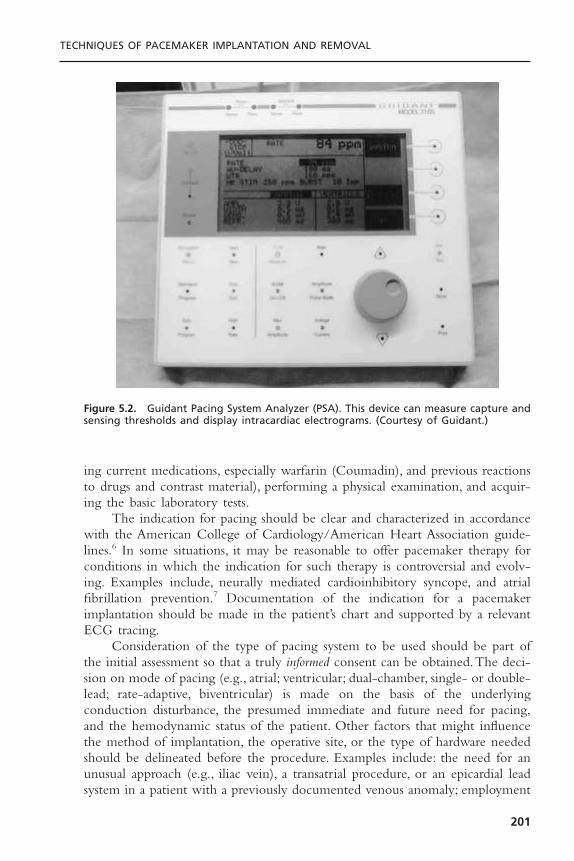
ing current medications, especially warfarin (Coumadin), and previous reactionsto drugs and contrast material), performing a physical examination, and acquir-ing the basic laboratory tests.
The indication for pacing should be clear and characterized in accordancewith the American College of Cardiology/American Heart Association guide-lines.6 In some situations, it may be reasonable to offer pacemaker therapy forconditions in which the indication for such therapy is controversial and evolv-ing. Examples include, neurally mediated cardioinhibitory syncope, and atrialfibrillation prevention.7 Documentation of the indication for a pacemakerimplantation should be made in the patient’s chart and supported by a relevantECG tracing.
Consideration of the type of pacing system to be used should be part ofthe initial assessment so that a truly informed consent can be obtained.The deci-sion on mode of pacing (e.g., atrial; ventricular; dual-chamber, single- or double-lead; rate-adaptive, biventricular) is made on the basis of the underlyingconduction disturbance, the presumed immediate and future need for pacing,and the hemodynamic status of the patient. Other factors that might influencethe method of implantation, the operative site, or the type of hardware neededshould be delineated before the procedure. Examples include: the need for anunusual approach (e.g., iliac vein), a transatrial procedure, or an epicardial leadsystem in a patient with a previously documented venous anomaly; employment
TECHNIQUES OF PACEMAKER IMPLANTATION AND REMOVAL
201
Figure 5.2. Guidant Pacing System Analyzer (PSA). This device can measure capture andsensing thresholds and display intracardiac electrograms. (Courtesy of Guidant.)
of an active-fixation ventricular lead in a patient with severe tricuspid regurgi-tation or corrected transposition of the great vessels; and the use of a steroidlead in a patient with a pacing history complicated by exit block.These factorscomprise an extensive series of decisions that must be carefully made well beforethe patient enters the procedure room (Fig. 5.3). Thorough preparation is crit-ical to minimizing problems at implant.
COST-EFFECTIVENESSGreat emphasis is currently being placed on the cost-effectiveness of medicalcare, especially those aspects of care that are procedurally centered. Ideally, atten-tion to cost-effectiveness is accompanied by increased quality of care. Hospitaladministrators have increasingly focused on the throughput of patients, the costof specific devices, and the level of patient satisfaction. Mechanisms of clinicalpractice improvement that may reduce cost yet increase the quality of care have been used.8 Practice guidelines, critical paths, and other methods of standardizing care will likely become more widespread. Physicians must con-tinue to play a leading role in cost constraint without compromising optimalpatient care.
INFORMED CONSENTIt is the implanting physician’s responsibility to obtain informed consent fromthe patient (or the patient’s family) before the procedure. An honest appraisal ofthe anticipated risks and benefits, acute and long-term, must be given alongwith an explanation of alternatives. This should be relevant to the particularindividual rather than the average patient.There should be a discussion not onlyof why pacing is being offered but also of why a particular mode of pacing isbeing considered. If the indication for pacing is controversial or investigational,more extensive counseling of the patient and documentation of such is neces-sary. Furthermore, the patients should be advised when there is reason to thinkthat a third-party insurer may not cover the specific indications. The need forlifelong follow-up evaluations should be emphasized, and mention should bemade of the eventuality of generator (and possibly lead) replacement. Finally,any physical or occupational restrictions imposed by the presence of a pace-maker should be thoroughly discussed with the patient.
It is good practice for the physician to establish a rapport with the patientand the patient’s family. All their questions must be answered and their fearsconcerning the procedure should be allayed, although it is important that noguarantees regarding outcome be given. The participation of other physicians at the time of implantation or during the follow-up assessments should bedescribed. The various members of the team should be in agreement about all aspects of the procedure so that the presentation to the patient is not confused.
CARDIAC PACING AND ICDS
202

TECHNIQUES OF PACEMAKER IMPLANTATION AND REMOVAL
203
Figure 5.3. Flow chart for decision process surrounding a new pacemaker implant. Alldecisions should be thoroughly considered before the patient enters the operating room.AF = atrial fibrillation; CHF = congestive heart failure; CS = coronary sinus; Dz = disease;HOCM = hypertrophic obstructive cardiomyopathy; Hx = history; LV = left ventricle; RAA= right atrial appendage; RVA = right ventricular apex; RVOT = right ventricular outflowtract.
PREIMPLANTATION ORDERS
Although outpatient pacemaker implantation can be performed, the usual prac-tice is to admit the patient to the hospital. This may be done on the day of theprocedure if the patient’s medical condition does not in itself mandate prior hos-pitalization. Routine pre-implant laboratory tests include a 12-lead ECG, a com-plete blood cell count (including platelet count), and measures of the prothrombinand activated partial thromboplastin times (aPTT), serum electrolytes, blood ureanitrogen (BUN), and creatinine. It may be valuable to have a recent posteroante-rior and lateral chest radiograph to compare to the post-procedure radiographs.
Food is withheld for 6 to 8 hours before the procedure. Hydration is main-tained by the establishment of an intravenous line, preferably with a large-borecannula in a vein of the upper extremity ipsilateral to the intended implant site.This will facilitate the injection of contrast should difficulty be encountered inachieving venous access. In general, the patient is allowed to continue whatevermedication he or she has been taking, with the obvious exception of anticoag-ulants, which are stopped prior to the procedure (see subsequent section). Thedosage of insulin or oral hypoglycemic drugs may require temporary alteration.
As many as 45% of patients requiring a pacemaker implant may be on oralanticoagulation.9 Their peri-implant management is often complicated andrelated to their indication for anticoagulation. There are three general options.The traditional approach has been to convert the patient on oral anticoagula-tion to intravenous unfractionated heparin. The latter can be stopped 4 to 6hours before implant if there is concern about the duration of time duringwhich the patient is not effectively anticoagulated (as for example, the presenceof a mechanical mitral valve). Implantation is usually performed when the Inter-national Normalized Ratio (INR) is 1.2 or less. If necessary, heparin may berestarted 8 to 12 hours after the procedure and warfarin may be reinitiated theday of the procedure or even the night before. It should be understood thatintravenous heparin administered within 24 hours after pacer or defibrillatorimplantation presents a significant risk (up to 20%) of pocket hematoma for-mation; this risk is five times that encountered in an unanticoagulated patient.10
Resumption of intravenous anticoagulation should thus be deferred for as longas possible after implant and then only with careful attention to the PTT. Manyoperators now have abandoned intravenous heparin in favor of transitioningpatients on oral anticoagulation to subcutaneously administered low-molecular-weight heparin (LMWH), which may be given up to 12 to 18 hours beforeplanned implantation.This obviates pre-procedural hospitalization and is gener-ally well tolerated. Resumption of warfarin at its maintenance dose post proce-dure with simultaneous LMWH for 3 to 5 days allows for the outpatienttransition back to oral anticoagulation.The risk of post-procedure bleeding withLMWH is thought to be similar to that experienced with unfractionatedheparin. There are, however, no randomized controlled trials demonstrating thesafety and efficacy of LMWH compared to standard unfractionated heparin forthis indication. The third option for managing the patient on warfarin is to
CARDIAC PACING AND ICDS
204

perform the procedure without reversal of the anticoagulant. Recently Giudiciand colleagues reported excellent results with this strategy in a series of 470patients having a mean INR of 2.6.9 The authors used meticulous implantationtechnique and suggest that the risk of pocket bleeding is not prohibitive becausehemostasis in these procedures is primarily a function of capillary vasocon-striction and platelet activity. It should be emphasized, however, that this approachis associated with potential risk and is not, at this time, standard practice.
Antibiotic prophylaxis is controversial, but there has been a suggestion thatits use, either systemic or local, decreases the incidence of infection.11 A meta-analysis of randomized trials that used a systemic antibiotic supports the use ofprophylactic antibiotic to prevent infection associated with permanent pace-maker implantation.12 In an accompanying report, the same investigators suggested that contamination by local flora cultured at the site of implant canresult in pacemaker-related infections presenting months later.13 We routinelygive a drug active against Staphylococcus (nafcillin, cephalosporin, vancomycin,etc.) before the procedure and for 24 hours after the procedure. Procedures thatare prolonged, complicated by potential breaches in sterility, or are “redo” innature are empirically given slightly longer courses of therapy (3 to 5 days).
The implant site (typically the area from above the nipple line to the angleof the jaw bilaterally) should be cleaned just before the patient’s arrival in thepacemaker laboratory. Although shaving the surgical site is controversial, I con-tinue to have this done. A reliable intravenous line is established in the prep areaand intravenous fluids administered for hydration. Mild pre-procedural seda-tion (e.g., 5–10mg of diazepam [Valium] and 25–50mg of diphenhydramine[Benadryl], orally) is given in the prep area. This will be augmented by intra-venous sedatives/analgesics during the procedure (e.g., 0.5–1mg of midazolam,25–50mg fentanyl) as needed.
Care should be taken not to oversedate patients, especially the elderly.Drugs to reverse sedation should be readily available: intravenous flumazenil in0.2-mg increments reverses midazolam; intravenous naloxone in 0.2-mg incre-ments reverses fentanyl. On rare occasions for particular patients (such as chil-dren or emotionally disturbed patients), light general anesthesia may be needed.If such a situation is anticipated, appropriate arrangements with an anesthesiol-ogist should be made in advance.
PATIENT PREPARATIONOn entering the procedure room, the patient is placed on the support in sucha way as to facilitate access to the specific operative site. Physiologic monitor-ing (ECG, automated blood pressure, and pulse oximetry) should be quicklyestablished so that rhythm disturbances may be detected and treated. The operative site is prepared with an antiseptic solution, wiped dry, and a plasticadhesive sterile field is applied. Disposable towels and drapes are liberally appliedto provide a large sterile workplace and to minimize the risk of accidental con-tamination. A separate adhesive plastic pocket is affixed to the lateral aspect of
TECHNIQUES OF PACEMAKER IMPLANTATION AND REMOVAL
205
the procedure site to collect draining fluid and sponges. A sterile plastic coveris placed over the image intensifier and the leaded glass shield (if used) to avoidinadvertent contamination of the sterile field during the procedure.
IMPLANT PROCEDURESite
Access to the right heart for permanent pacing has been achieved by intro-ducing leads into any of a number of veins, including the subclavian, cephalic,internal or external jugular, and iliofemoral.14 Typically, the choice of venousentry site determines where the generator will be housed, although lead exten-ders can be used when necessary to allow a more remote positioning of thedevice. In most cases a cephalic, axillary, or subclavian vein is used, and the pace-maker is placed subcutaneously in the adjacent infraclavicular region. On occa-sion, however, the generator may be implanted under the pectoral muscle or inan abdominal position. For women in whom there is a concern about cosmeticappearance, an inframammary incision may be performed and the pacemakerplaced under the breast.15 In such circumstances, it may be wise to enlist theassistance of a plastic surgeon.
The site of implant is influenced by the factors listed in Figure 5.3. Mostoften the left side is chosen because most patients are right handed and thereis a less acute angle between the left subclavian and the innominate vein thanexists on the right side. A disadvantage of using the left side is the small (0.3%to 0.5%) incidence of persistent left superior vena cava with drainage into thecoronary sinus, which complicates lead positioning. Suspicion of this anomalymay be raised by finding greater distension and a double A wave in the leftjugular vein compared with that of the right vein, a left paramediastinal venouscrescent on the chest radiograph, and an enlarged coronary sinus on echocar-diography.16 Contrast echocardiography or venography will confirm the diag-nosis. Although both single-chamber ventricular and dual-chamber systems17
have been placed through a persistent left superior vena cava via the coronarysinus, it is preferable to approach implantation from the right side when thisanomaly exists (Fig. 5.4). Rarely, there is a coexistent absence of the right supe-rior vena cava with all brachycephalic flow entering into the coronary sinus.Such a condition should be excluded before implantation is attempted from theright side in patients with a persistent left superior vena cava. The increasingexperience with pacing from the coronary venous system coupled with the rel-ative ease of entering these vessels in the case of persistent left superior venacava suggests that this is a reasonable alternative in the latter patients. Otheroptions for patients with anomalous venous drainage include an ilio-femoralapproach or a traditional epicardial implantation, which now may be performedthrough a subxyphoid or thorascopic approach.
Venous AccessFigure 5.5 illustrates the two major easily identifiable landmarks (clavicle anddeltopectoral groove) for implantation in a left infraclavicular site.Venous access
CARDIAC PACING AND ICDS
206
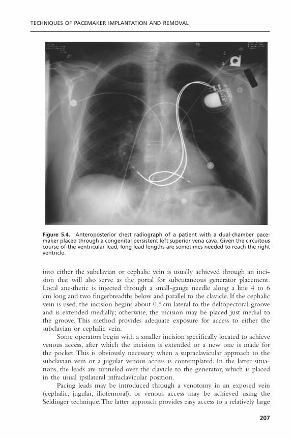
into either the subclavian or cephalic vein is usually achieved through an inci-sion that will also serve as the portal for subcutaneous generator placement.Local anesthetic is injected through a small-gauge needle along a line 4 to 6cm long and two fingerbreadths below and parallel to the clavicle. If the cephalicvein is used, the incision begins about 0.5cm lateral to the deltopectoral grooveand is extended medially; otherwise, the incision may be placed just medial tothe groove. This method provides adequate exposure for access to either thesubclavian or cephalic vein.
Some operators begin with a smaller incision specifically located to achievevenous access, after which the incision is extended or a new one is made forthe pocket. This is obviously necessary when a supraclavicular approach to thesubclavian vein or a jugular venous access is contemplated. In the latter situa-tions, the leads are tunneled over the clavicle to the generator, which is placedin the usual ipsilateral infraclavicular position.
Pacing leads may be introduced through a venotomy in an exposed vein(cephalic, jugular, iliofemoral), or venous access may be achieved using theSeldinger technique.The latter approach provides easy access to a relatively large
TECHNIQUES OF PACEMAKER IMPLANTATION AND REMOVAL
207
Figure 5.4. Anteroposterior chest radiograph of a patient with a dual-chamber pace-maker placed through a congenital persistent left superior vena cava. Given the circuitouscourse of the ventricular lead, long lead lengths are sometimes needed to reach the rightventricle.

CARDIAC PACING AND ICDS
208
Figure 5.5. Surface landmarks in a patient about to undergo pacemaker implantation.The top solid line indicates the inferior margin of the left clavicle. The dashed line 2.0cm beneath indicates the site of incision, from which access to the subclavian, axillary,and cephalic veins is possible. The more vertical solid line indicates the deltopectoralgroove in which the cephalic veins are found. Incision at this site allows access to thecephalic, axillary, and subclavian veins.

central vein, obviating the need for surgical dissection. In addition, the use ofthe dilator-sheath technique facilitates the introduction of multiple large leadsand provides a means (via a retained guidewire) to reenter the venous systemshould that be necessary (e.g., if change from a passive to an active-fixation leadis needed because a stable position is not found with the former). Nevertheless,the blind subclavian stick poses the risk of injury to nearby structures, includ-ing the artery, lung, thoracic duct, and nerves, and it is the most hazardous partof the implantation procedure.1
The Subclavian MethodThe Seldinger approach to the subclavian vein has long been a popular methodof gaining rapid access to the central venous circulation. The introduction ofthe tear-away sheath provided an effective means for the insertion of perma-nent pacemaker leads, and this method is now the most frequently used. Theefficacy and safety of subclavian entry are increased by taking measures todistend the vein (proper hydration, leg elevation) and place it in the proper posi-tion (by placing a wedge under the patient’s shoulders and by adduction of theipsilateral upper extremity).
The traditional approach to the subclavian “stick” uses an 18-gauge explor-ing needle. My current practice is to use a smaller gauge micropuncture systemfor all percutaneous vascular access. I think that this is a bit safer and perhapsless painful. The needle, attached to a 10-mL syringe containing a few milli-liters of local anesthetic, is introduced through an incision that has been bluntlydissected to the underlying prepectoral fascia.The tip of the needle is advanced,bevel down, along this tissue plane at the level of the junction of the medialand middle thirds of the clavicle and directed toward a point just above thesternal notch. Small amounts of anesthetic may be injected along this course.On reaching the clavicle, the needle’s angle of entry with respect to the thoraxis increased until the tip slips under the bone. Negative pressure is exerted onthe syringe as the needle is advanced so that blood is aspirated on entrance intothe vein.
Once under the clavicle, the needle should not be redirected; doing so maylacerate underlying structures. If venous entry is not obtained, the needle shouldbe withdrawn, cleared of any obstructing tissue, and reinserted in a slightly dif-ferent direction. Inadvertent arterial entry is apparent with the appearance ofpulsatile bright red blood. Prompt withdrawal of the needle and compression atits entry site under the clavicle is usually all that is necessary to close the entrypoint. Repeated unsuccessful attempts to enter the vein suggest a deviation inanatomy or occlusion of the vessel. In either situation, the risk of complicationis increased with additional blind needle insertions; no more than three suchattempts should be made, at which point one should consider a contrast injec-tion to determine vessel patency and to provide a road map to its site.
Adequate opacification of the subclavian vein is achieved by the injectionof a bolus of 20 to 40mL of iodinated contrast through a large-bore cannulain an ipsilateral arm vein. This should be followed immediately by injection of
TECHNIQUES OF PACEMAKER IMPLANTATION AND REMOVAL
209

a saline “chaser” to hasten the transit of the contrast solution. The amount offluid and rate of injection is gauged by fluoroscopic observation of the courseof dye into the central veins. It is important that enough contrast be used andthat adequate time be given for the contrast to fill the subclavian vein or col-lateral vessels. If the vessel is patent, there is often enough lingering contrast toallow an exploring needle to be directed at it.
It is helpful to record the injection on videotape or digitally so that theprocedure may be reviewed. Some digital systems allow superimposition of real-time fluoroscopy on a stored contrast-filled image, which greatly facilitates theprocedure. This technique may be especially useful in device upgrade proce-dures as a way to avoid needle damage to a preexisting lead. On occasion, aformal venogram may be obtained to document the status of the venous systembefore or after implantation (see Fig. 5.1).
On successful entry of the needle into a vessel, the character of the aspi-rated blood is examined. Dark nonpulsatile flow suggests a venous location;however, nonpulsatile flow does not exclude arterial entry, and pulsatile flow issometimes noted from a vein (e.g., tricuspid regurgitation, right heart failure,cannon waves). Once vascular access is achieved, the syringe is detached (takingcare to prevent air from entering the venous system) and a J-tipped guidewireis inserted through the needle (or small introducer sheath in the case of micro-puncture access) and advanced under fluoroscopy to the inferior vena cava(IVC). If this is accomplished, inadvertent aortic entry is precluded; merelyobserving the guidewire coursing to the right of the sternum or even into aventricular chamber does not exclude its presence in a tortuous ascending aortaor its passing retrograde into the left ventricle.
If resistance to advancement of the guidewire is encountered, the guidewireshould be withdrawn through the needle with great care to prevent shearingoff the distal wire by the needle tip. If any difficulty is encountered with with-drawal, either the wire and the needle should be withdrawn together or, ifenough wire has been passed into the vein, the needle may be withdrawn anda small lumen plastic catheter advanced over the wire and into the vein. In thelatter situation, contrast may then be injected through the catheter to identifythe problem and a more torqueable wire capable of being directed appropri-ately can be introduced.
Once the guidewire is positioned in the IVC, a commercially available peel-away sheath-dilator combination (7 to 12F depending on lead(s) size) may beadvanced over the wire into the superior vena cava, which will provide access forthe introduction of pacing leads.The relatively stiff, straight dilator may be moldedinto a gentle curve by the operator before insertion. Advancement of the deviceunder the clavicle may be facilitated by torquing it as if it were being screwedinto place. Considerable resistance may be encountered if the subclavian vein hasbeen entered medially through a fibrous or calcified ligament.The use of a stifferguidewire may be advantageous in such a situation, as might the passage of ini-tially small, then progressively larger dilators. Entrance into such a location maybe a marker for future lead entrapment, thus one may consider seeking a more
CARDIAC PACING AND ICDS
210
lateral entry site (see subsequent discussion). Excessive force should not be nec-essary once the sheath has entered the vein. Fluoroscopic confirmation of properalignment of dilator and wire is necessary if resistance is encountered. On occa-sion,countertraction on the wire while advancing the dilator is helpful.The sheathshould not be allowed to slide over the tapered tip of the dilator, nor should thedilator be unprotected by a guidewire at any time during advancement.
Once it is properly positioned in the superior vena cava, the dilator isremoved while the guidewire is retained within the sheath to allow for theintroduction of a second sheath if necessary. A clamp should be applied to theend of the guidewire to prevent its accidental migration into the vein. Careshould be taken to limit the possibility of the aspiration of air through the large-bore open sheath by pinching its orifice until the lead is inserted. The patientshould not be heavily sedated and should be instructed to avoid deep inspira-tion during this process.The use of tear-away sheaths with hemostatic valves arenow often used and are helpful in limiting bleeding and preventing airembolism.The pacing lead is introduced alongside the guidewire and advancedinto the right atrium or IVC, at which time the sheath is withdrawn and peeledapart proximal to the venous entry site to prevent injury to the vessel. If a dual-chamber device is to be employed, the retained wire is used to introduce asecond sheath. If only one lead is to be used, it is still wise to retain theguidewire so that venous reentry is facilitated should the lead prove inadequate.It has been suggested that the use of a larger single sheath may be beneficialby allowing the two leads to be introduced simultaneously, but the risk of airembolism would seem greater in this situation.An alternative technique has beendescribed in which two guidewires are inserted through a single introducer andthen each used separately to insert an introducer sheath. Some implanters preferto use two separate subclavian punctures when placing a dual chamber pacingsystem to limit lead interaction at the access site.This potential benefit does not,in my opinion, justify the risk of a second needle access.
The Axillary Vein ApproachThere is evidence that the traditional percutaneous subclavian approach resultsin access to the medial aspect of the vein, which may result in entrapment ofthe lead between the subclavius muscle and the costoclavicular ligament.18,19
Forces exerted on leads in this position may predispose them to insulationfailure. This may be most problematic for some polyurethane leads (especiallythose made with Pellethane 80A) which appear to be particularly susceptible tofailure when placed via the subclavian route.20 These observation have led tothe development of techniques to access the axillary vein by direct needle stick,which have yet to be widely adopted. The cephalic venotomy (see subsequentdiscussion) avoids the effects of the medial subclavicular musculotendinouscomplex. Our group has derived a technique of lateral access using a micro-puncture system and contrast venography (Fig. 5.6).21 This method appears tobe safe and effective; in the hands of non-surgeons, it is more likely to be suc-cessful than cephalic vein cutdown.22
TECHNIQUES OF PACEMAKER IMPLANTATION AND REMOVAL
211
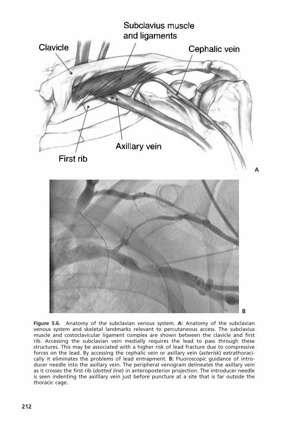
212
Figure 5.6. Anatomy of the subclavian venous system. A: Anatomy of the subclavianvenous system and skeletal landmarks relevant to percutaneous access. The subclaviusmuscle and costoclavicular ligament complex are shown between the clavicle and firstrib. Accessing the subclavian vein medially requires the lead to pass through these structures. This may be associated with a higher risk of lead fracture due to compressiveforces on the lead. By accessing the cephalic vein or axillary vein (asterisk) extrathoraci-cally it eliminates the problems of lead entrapment. B: Fluoroscopic guidance of intro-ducer needle into the axillary vein. The peripheral venogram delineates the axillary veinas it crosses the first rib (dotted line) in anteroposterior projection. The introducer needleis seen indenting the axilllary vein just before puncture at a site that is far outside the thoracic cage.
A
B
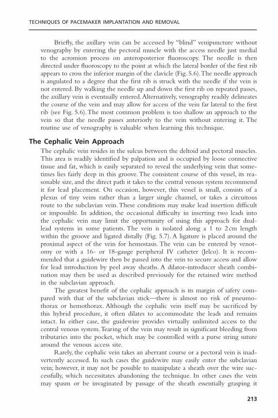
TECHNIQUES OF PACEMAKER IMPLANTATION AND REMOVAL
213
Briefly, the axillary vein can be accessed by “blind” venipuncture withoutvenography by entering the pectoral muscle with the access needle just medialto the acromion process on anteroposterior fluoroscopy. The needle is thendirected under fluoroscopy to the point at which the lateral border of the first ribappears to cross the inferior margin of the clavicle (Fig. 5.6).The needle approachis angulated to a degree that the first rib is struck with the needle if the vein isnot entered. By walking the needle up and down the first rib on repeated passes,the axillary vein is eventually entered.Alternatively, venography readily delineatesthe course of the vein and may allow for access of the vein far lateral to the firstrib (see Fig. 5.6).The most common problem is too shallow an approach to thevein so that the needle passes anteriorly to the vein without entering it. Theroutine use of venography is valuable when learning this technique.
The Cephalic Vein ApproachThe cephalic vein resides in the sulcus between the deltoid and pectoral muscles.This area is readily identified by palpation and is occupied by loose connectivetissue and fat, which is easily separated to reveal the underlying vein that some-times lies fairly deep in this groove.The consistent course of this vessel, its rea-sonable size, and the direct path it takes to the central venous system recommendit for lead placement. On occasion, however, this vessel is small, consists of aplexus of tiny veins rather than a larger single channel, or takes a circuitousroute to the subclavian vein.These conditions may make lead insertion difficultor impossible. In addition, the occasional difficulty in inserting two leads intothe cephalic vein may limit the opportunity of using this approach for dual-lead systems in some patients. The vein is isolated along a 1 to 2cm lengthwithin the groove and ligated distally (Fig. 5.7). A ligature is placed around theproximal aspect of the vein for hemostasis. The vein can be entered by venot-omy or with a 16- or 18-gauge peripheral IV catheter (Jelco). It is recom-mended that a guidewire then be passed into the vein to secure access and allowfor lead introduction by peel away sheaths. A dilator-introducer sheath combi-nation may then be used as described previously for the retained wire methodin the subclavian approach.
The greatest benefit of the cephalic approach is its margin of safety com-pared with that of the subclavian stick—there is almost no risk of pneumo-thorax or hemothorax. Although the cephalic vein itself may be sacrificed bythis hybrid procedure, it often dilates to accommodate the leads and remainsintact. In either case, the guidewire provides virtually unlimited access to thecentral venous system.Tearing of the vein may result in significant bleeding fromtributaries into the pocket, which may be controlled with a purse string suturearound the venous access site.
Rarely, the cephalic vein takes an aberrant course or a pectoral vein is inad-vertently accessed. In such cases the guidewire may easily enter the subclavianvein; however, it may not be possible to manipulate a sheath over the wire suc-cessfully, which necessitates abandoning the technique. In other cases the veinmay spasm or be invaginated by passage of the sheath essentially grasping it

and preventing its advancement or removal. Application of a vasodilator (e.g.,nitroglycerine) or actually cutting the constricting vein, exposed by pulling back on the dilator, may be necessary to fully insert the sheath. Despite thesepotential limitations of the cephalic technique, an experienced operator can suc-cessfully implant leads by this approach in most cases when it is attempted.Occasionally, a floppy or hydrophobically coated wire is necessary to negotiatethe cephalic-axillary vein junction. Pulling the arm caudally will flatten theshoulder and facilitate passage through the acute angle formed by this juncture.
THE PACEMAKER POCKETThe pacemaker is usually placed in a subcutaneous position near the site ofvenous entry. Generators have continued to decrease in size and can be placedquite easily in most patients, including those having a paucity of subcutaneous
CARDIAC PACING AND ICDS
214
Figure 5.7. Surgical access to the right cephalic vein at pacemaker implant. The orien-tation of the patient in the figure is given. The moderately large cephalic vein (arrow)lies in the dissected deltopectoral groove and has ligatures placed proximally and dis-tally. This vein can be accessed directly with venotomy or with a peripheral IV catheterto introduce a guidewire and peel away sheath.
tissue. Most often, the device is placed in the infraclavicular area through theincision used to obtain venous access. Local anesthesia is applied to the subcu-taneous tissue, which is then dissected down to the prepectoral fascia. Placingthe pocket too superficially in a subcuticular pocket may lead to a pain syn-drome requiring re-operation.23 A pocket directed inferomedially over the pec-toral fascia and large enough to accommodate both the generator and redundantlead is made in this tissue plane by blunt dissection using the fingers.Too smalla pocket may result in tension exerted on the overlying tissue by the implantedhardware; too large a pocket invites future migration or “flipping over” of thegenerator. Augmentation of anesthesia with a rapidly acting parenteral agent isrecommended during the brief time it takes for pocket creation because thismay be the most uncomfortable part of the procedure. Attention to hemostasisis necessary, but significant bleeding rarely accompanies blunt dissection andBovie cautery in the proper tissue plane. Stripping away the pectoral fasciaduring the dissection often leads to excessive bleeding from the denuded muscle.On completion of its formation, the pocket may be copiously flushed withantibacterial solution and temporarily packed with radiopaque sponges. Careshould be taken to account for all sponges used in this fashion. Even aradiopaque sponge may be missed by fluoroscopy if it is under the generatorand only casual observation is made.
In some circumstances (e.g., sparse subcutaneous tissue, large generator/defibrillator, impending erosion from a previous device, concerns about cosmeticappearance) the generator may be placed subpectorally or under the breast.These procedures should be well planned ahead of time and, when necessary,arrangements made with appropriate specialists (such as a plastic surgeon). Thesubpectoral site is best accessed by dissecting the natural plane between the pec-toralis major and minor muscles. This plane is identified by blunt dissection inthe deltopectoral groove and carried inferiorly and medially. Alternatively, amuscle-splitting incision can be made in the body of the pectoralis major itself.Care should be taken to note when a subpectoral position has been chosen so that operators will be aware of such should future generator exchange benecessary. An “intra-pectoral” pocket has been recently described by Kistler andcolleagues24 that appears easy to access and safe to create.
Pockets located at a distance from the site of lead insertion require thatthe leads (with or without extenders) be tunneled through subcutaneous tissueto its location. A simple method for tunneling leads from the infraclavicular siteto a submammary pacemaker pocket by the use of a long needle, guidewire,and dilator–introducer set has been described by Roelke and colleagues.25
LEAD IMPLANTATIONA variety of leads are available for endocardial placement. They differ in com-position, shape, electrode configuration, and method of fixation. Special leadsthat contain steroid-eluting collars or biosensors have been developed. Passivefixation leads have tines or fins that anchor them in the trabeculated right ven-
TECHNIQUES OF PACEMAKER IMPLANTATION AND REMOVAL
215

tricle or atrial appendage; active-fixation leads employ a helix that provides amechanism for actually fixing the lead to the endocardium. The helix may beextrudable and retractable, or may be fixed at the tip. In the latter situation, thehelix is covered with an absorbable agent to facilitate passage of the lead to itssite of implantation, by which time absorption of the material exposes the helixand allows it to be fixed to the heart. I prefer the extrudable devices, which areeasier to remove if necessary. Both active and passive types of leads have advan-tages and disadvantages (Box 5.1) and may be used for either atrial or ventric-ular placement. Steroid-eluting active-fixation leads may offer some benefit interms of lowered subacute and possibly chronic thresholds. Despite the progressin lead design and their overall excellent performance, the failure over time ofseveral models of these devices remains a cause for concern.26
Before introduction, leads should be inspected for imperfections and, if theyare to be inserted through a sheath, to confirm that this can be done easily inthe presence of a retained guidewire. Active-fixation leads should be tested toensure that the helix extrudes and retracts appropriately. Care should be takento ensure that the screw does not pick up debris during this process. It is impor-tant to confirm that the connector pin of the lead is appropriate for the gen-erator that has been selected. The suture sleeve should be positioned at theproximal portion of the lead and prevented from migrating distally during leadplacement.
Stylets are used to supply a degree of stiffness and shapeability to the lead.The stylets may vary in stiffness and length and in some cases are specially con-figured to engage an active-fixation mechanism. They must be matched for aspecific purpose to the lead. Stylets should be kept clean and dry to facilitateinsertion and withdrawal from the lead. Torque applied to a shaped stylet mayhelp rotate the lead. Special stylets are now available that allow for in situ alter-ation of the degree of curve they provide to the lead tip, which may facilitateatrial placement. Although not required to retract the lead, the stylet provides“body” to the lead and may be needed to advance it to an optimal position.
CARDIAC PACING AND ICDS
216
Box 5.1. Lead Characteristics
1. Active fixation lead• Easy passage• Low acute dislodgment rate• Unrestricted positioning• Easier removal of chronic implant• Higher capture thresholds
2. Passive fixation lead• Greater electrode variety• Lower thresholds• More difficult passage• More difficult chronic removal• Higher early dislodgment rate
Leads may be inserted directly into a venotomy or through a peel-awaysheath.The central venous system is usually traversed easily and the lead advancedand “parked” in the low right atrium or inferior vena cava, pending introductionof a second lead or removal of the sheath. On occasion there may be difficultyin advancing the lead through the sheath.This is more common when there is asharp angle to be negotiated and the sheath kinks. The temptation to force thelead through the sheath should be resisted to avoid damage to the lead. With-drawing the sheath slightly, advancing the retained guidewire along with the lead,and sometimes withdrawing the stylet to soften the lead tip may prove helpful.
Although the retained-guidewire approach facilitates the insertion of the twoleads required for dual-chamber pacing, manipulation of one lead may affect theposition of the other.There is also a potential for a lead or guidewire to be with-drawn accidentally if they are not attended to closely. Some implanters feel thattwo independent sheaths be used and not withdrawn until both leads have beenpositioned, or that separate venous sites (e.g., cephalic and subclavian or two sep-arate subclavian entry sites) be accessed for each lead. If a modicum of care is taken,however, two leads may be inserted and positioned by using the retained-guidewiretechnique, which is quicker and probably safer than the alternative approaches.
Good fluoroscopic imaging is a key to successful lead implantation,however in unusual situations, such as with a pregnant patient, echocardiogra-phy has been used to help position leads to limit radiation exposure.27
Ventricular Lead PositioningIn dual-chamber systems, the right ventricular lead is usually positioned firstbecause it may supply back-up pacing, its position is usually a bit less tenuousthan that of the atrial lead, and it is usually considered the most important ofthe leads. Left ventricular lead placement is described in the chapter on cardiacresynchronization therapy. On occasion the lead may seem to enter the rightventricle with little assistance from the operator, but more often some manip-ulation is necessary. Withdrawing the straight stylet a few inches allows one tocatch the lead tip in the right atrium; further advancement of the lead will causeits distal portion to form a J shape, which may then be rotated toward the tri-cuspid valve. Slight retraction results in prolapse into the right ventricle, at whichtime the lead can be either advanced into the pulmonary artery or directeddown toward the apex by advancing the stylet while the lead is slowly pulledback. Prolapsing the lead ino the ventricle ensures that the lead is not in thecoronary sinus and is not passing through the tricuspid valve apparatus. Entranceinto the pulmonary artery confirms that the lead has traversed the right ven-tricle and is neither in the atrium nor in the coronary sinus.The lead may thenbe pulled back as the stylet is advanced (as described previously).
Once the lead tip falls toward the apex, the patient is asked to inspire deeplyand the lead is advanced into place.This procedure is often accompanied by ven-tricular ectopy, the absence of which suggests that the lead is not in the ventri-cle. An alternative method of gaining entry to the ventricle is to form the styletinto a dogleg or a J shape and use it to direct the lead across the tricuspid valve.
TECHNIQUES OF PACEMAKER IMPLANTATION AND REMOVAL
217
Once it is in the right ventricle, the shaped stylet may be replaced with a straightone to facilitate positioning at the apex. The proper fluoroscopic appearance ofthe right ventricular apical lead is one in which the lead’s tip is well to the leftof the spine and is pointing anteriorly and slightly caudal (Fig. 5.8).
In the anteroposterior projection it may not be possible to distinguishwhether a lead is in a posterior coronary vein, the left ventricle, or the rightventricular apex. Oblique views and the electrocardiographic pattern of ven-tricular activation during pacing may be helpful (Fig. 5.9). In patients with leftventricular prominence and/or counterclockwise rotation of the heart, the leadtip may not appear to extend far enough to the left border of the cardiac sil-houette. Imaging in the right anterior oblique position may be helpful in suchcircumstances; observing the position of the lead with respect to the tricuspidvalve allows an estimation of how far the lead is in the ventricle. Pacing at 10V output is performed to exclude diaphragmatic stimulation by the lead.
Once in place, the tip should maintain a relatively stable position and notappear to be bouncing with cardiac contraction. A slight loop of lead is left inthe atrium to avoid tension at the tip during deep inspiration.Too large a loopmay result in ectopy, lead displacement, and possible chronic perforation at thetip. Lead position should be checked with the stylet withdrawn.
Although an apical position is preferred for reasons of stability, there areoccasions when another location in the right ventricle is required (e.g., aretained ventricular lead, which might result in electrical potentials being generated between it and the new lead). Efforts to obtain a more physiologicactivation sequence and, presumably, contraction from ventricular stimulationhave led some to advocate positioning the lead in the right ventricular outflowtract28 or at the ventricular septum (Fig. 5.8). In these circumstances, the use ofan active-fixation lead is required. The hemodynamic benefits of routinelyseeking such a position compared with the stability of the traditional apical loca-tion are unproven but this position eliminates the risk of extracardiac perfora-tion and diaphragmatic stimulation.
When a reasonable position is obtained, preliminary measurements of theelectrical parameters are made.This is usually accomplished with the stylet with-drawn about halfway so as not to interfere with the position of the lead tip and to facilitate movement of the lead body should that be necessary. Whenactive-fixation leads are used, such measurements may be taken before exten-sions of the helix, as a screen of the implant site prior to fixing the leads. If theparameters are not good an alternative position may be tried. Once a reason-able site is established the helix is extruded and the parameters re-measured.Failure to record a large current of injury after fixing active-fixation leads sug-gests an unstable lead position. Active-fixation leads vary in the ways they inter-face with the heart; the helix may be electrically active, the distal electrode maybe active, or both the helix and a distal electrode may be active.Adequate pacingcharacteristics may not be found immediately after extension of the helix: thescrew may not have entered the myocardium, the site may be inadequate, orlocal tissue injury may have occurred consequent to entry of the helix.To place
CARDIAC PACING AND ICDS
218

a lead in the outflow tract or septum, the lead is prolapsed into the pulmonaryartery as described. By withdrawing the lead with a curved stylet and torqueto drive the tip into the septum, the septum can be mapped and the lead fixed.All lead positions should be confirmed by both left anterior oblique and rightanterior oblique views in the laboratory. It is common for capture thresholds todecrease significantly 15 to 30 minutes after active fixation.29 If parameters are
TECHNIQUES OF PACEMAKER IMPLANTATION AND REMOVAL
219
LAORAO
Figure 5.8. A: RAO and LAO views of right ventricular apical lead position at the timeof implant. The patient has a prosthetic mitral valve in place. The ventricular lead is posi-tioned with the tip at the right ventricular apex, well beyond the spine shadow, as shownhere. The slight downward position of the tip is desirable. Some indentation of the ven-tricular lead at the level of the tricuspid valve is common. In LAO the lead lies againstthe ventricular septum. B: PA and lateral views of dual chamber system after implant.The right ventricular lead is positioned in the midright ventricular septum. Note the ante-rior direction of this lead in the lateral projection. The atrial lead is positioned in theright atrial appendage and is also oriented anteriorly.
A
B

unacceptable, the helix may be retracted and a new site tested. It has been sug-gested that serial measurements of lead impedance be used to confirm fixationof helical screw electrodes, because with fixation the impedance may increaseapproximately 200ohms in the ventricle and 50ohms in the atrium.30 At timesone may be unable to retract the screw either because the mechanism has beendamaged or because tissue has become impacted in the helix. It might still bepossible to reposition the lead and fix it to the myocardium by rotating theentire lead (indeed, some active-fixation leads have nonretractable screws);however, replacement of the lead with a new one is probably a better option.
Threshold parameters tested with a PSA define the electrical adequacy oflead position. This is accomplished using a set of connector cables, which can
CARDIAC PACING AND ICDS
220
A
B
Figure 5.9. A: ECG demonstrated pacing with right bundle branch block morphology.The anteroposterior chest radiograph was consistent with right ventricular apical posi-tion; however, the lateral radiograph demonstrated the lead in the left ventricle (see Fig.5.13). B: Left bundle branch block pattern with paced events was seen following reposi-tioning of the lead into the right ventricle.
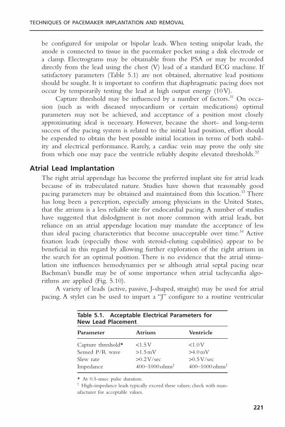
be configured for unipolar or bipolar leads. When testing unipolar leads, theanode is connected to tissue in the pacemaker pocket using a disk electrode ora clamp. Electrograms may be obtainable from the PSA or may be recordeddirectly from the lead using the chest (V) lead of a standard ECG machine. Ifsatisfactory parameters (Table 5.1) are not obtained, alternative lead positionsshould be sought. It is important to confirm that diaphragmatic pacing does notoccur by temporarily testing the lead at high output energy (10V).
Capture threshold may be influenced by a number of factors.31 On occa-sion (such as with diseased myocardium or certain medications) optimal parameters may not be achieved, and acceptance of a position most closelyapproximating ideal is necessary. However, because the short- and long-termsuccess of the pacing system is related to the initial lead position, effort shouldbe expended to obtain the best possible initial location in terms of both stabil-ity and electrical performance. Rarely, a cardiac vein may prove the only sitefrom which one may pace the ventricle reliably despite elevated thresholds.32
Atrial Lead ImplantationThe right atrial appendage has become the preferred implant site for atrial leadsbecause of its trabeculated nature. Studies have shown that reasonably goodpacing parameters may be obtained and maintained from this location.33 Therehas long been a perception, especially among physicians in the United States,that the atrium is a less reliable site for endocardial pacing. A number of studieshave suggested that dislodgment is not more common with atrial leads, butreliance on an atrial appendage location may mandate the acceptance of lessthan ideal pacing characteristics that become unacceptable over time.34 Activefixation leads (especially those with steroid-eluting capabilities) appear to bebeneficial in this regard by allowing further exploration of the right atrium inthe search for an optimal position. There is no evidence that the atrial stimu-lation site influences hemodynamics per se although atrial septal pacing nearBachman’s bundle may be of some importance when atrial tachycardia algo-rithms are applied (Fig. 5.10).
A variety of leads (active, passive, J-shaped, straight) may be used for atrialpacing. A stylet can be used to impart a “J” configure to a routine ventricular
TECHNIQUES OF PACEMAKER IMPLANTATION AND REMOVAL
221
Table 5.1. Acceptable Electrical Parameters for New Lead Placement
Parameter Atrium Ventricle
Capture threshold* <1.5V <1.0VSensed P/R wave >1.5mV >4.0mVSlew rate >0.2V/sec >0.5V/secImpedance 400–1000ohms† 400–1000ohms†
* At 0.5-msec pulse duration.† High-impedance leads typically exceed these values; check with man-ufacturer for acceptable values.
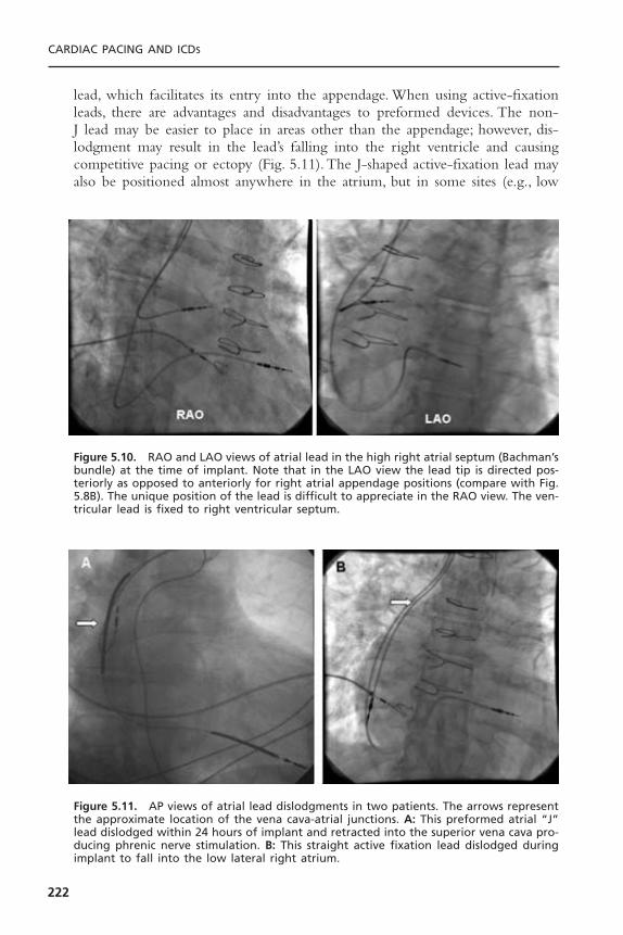
lead, which facilitates its entry into the appendage. When using active-fixationleads, there are advantages and disadvantages to preformed devices. The non-J lead may be easier to place in areas other than the appendage; however, dis-lodgment may result in the lead’s falling into the right ventricle and causingcompetitive pacing or ectopy (Fig. 5.11). The J-shaped active-fixation lead mayalso be positioned almost anywhere in the atrium, but in some sites (e.g., low
CARDIAC PACING AND ICDS
222
Figure 5.11. AP views of atrial lead dislodgments in two patients. The arrows representthe approximate location of the vena cava-atrial junctions. A: This preformed atrial “J”lead dislodged within 24 hours of implant and retracted into the superior vena cava pro-ducing phrenic nerve stimulation. B: This straight active fixation lead dislodged duringimplant to fall into the low lateral right atrium.
Figure 5.10. RAO and LAO views of atrial lead in the high right atrial septum (Bachman’sbundle) at the time of implant. Note that in the LAO view the lead tip is directed pos-teriorly as opposed to anteriorly for right atrial appendage positions (compare with Fig.5.8B). The unique position of the lead is difficult to appreciate in the RAO view. The ven-tricular lead is fixed to right ventricular septum.

atrium) its shape may cause undue tension at the site of attachment to the endo-cardium increasing the risk of dislodgment (see Fig. 5.11).
The atrial lead is inserted into the venous system with a straight stylet tofacilitate negotiation of the central veins. Positioning in the atrial appendage isattempted first.The lead is directed toward the high anterior atrium and allowedto take its J shape either by withdrawing the straight stylet (in preformed leads)or by inserting a J stylet (see Fig. 5.8B). Slow retraction of the “J” shaped leadresults in the tip’s entering the appendage, where it will appear to catch and takeon a characteristic to-and-fro motion with atrial activity. When it is well posi-tioned, slight rotation of the lead should not dislodge the tip, and deep inspira-tion opens the curve to an L configuration but no further. In some patients theatrial appendage may be quite large and trabeculae may be attenuated; in others,who have received cardiopulmonary bypass, the appendage may be oversewn. Ineither circumstance, placement of a preformed J lead may be difficult. Althoughsome implanters feel that amputation of the right atrial appendage at the time ofprevious cardiac surgery is a mandate for an active-fixation atrial lead, others findpassive fixation devices to be acceptable.35 We are most comfortable recommend-ing the routine use of active-fixation, steroid-eluting leads with normal or highimpedance for patients with prior cardiac surgery. To place a lead on the atrialseptum, allow the curve of the active fixation lead to form free in the body ofthe atrium and directed anteriorly. Rotate the lead to the septum in LAO viewand pull the lead up until the roof of the atrium is encountered (see Fig. 5.10).Opening the stylet to a curve less than 180 degrees facilitates reaching the septum.
Acceptable electrical parameters for atrial pacing are listed in Table 5.1. Asseen when positive fixation leads are used in the ventricle, there may be a sig-nificant improvement of the parameters during the first half hour; if borderlinevalues are obtained initially, it may be worthwhile to remeasure them after ashort wait. If poor values are obtained initially, however, it is best to search fora new position. The better the electrical characteristics, the more probable thatlong-term pacing will be successful. As with the ventricular lead, it is impor-tant to test for diaphragmatic pacing by temporarily stimulating the atrium athigh output (10V).
Epicardial and Transmyocardial Lead PlacementPermanent epicardial leads can be placed on the atrium and ventricles at tho-racotomy. Newer steroids eluting active fixation and atraumatic suture-on elec-trodes provide the best long-term thresholds. Chronic epicardial atrial leadperformance remains problematic, however.These leads must be passed betweenor beneath the ribs and then tunneled subcutaneously to the pocket.
When no venous access is available and the superior performance of endo-cardial lead placement is desired, transmyocardial placement may be indicated(Fig. 5.12). By thoracotomy, one or two leads can be passed through the rightatrial wall and positioned in the atrium and ventricle with use of fluoroscopy.Purse string sutures around the atriotomies prevent bleeding.The leads are thentunneled to the pocket.
TECHNIQUES OF PACEMAKER IMPLANTATION AND REMOVAL
223

SINGLE-LEAD VDD PACINGThe general principles of lead insertion are similar for the dual-chamber VDDsystems that use specially arrayed proximal atrial sensing electrodes as well as atip electrode to sense and pace the ventricle on a single lead.These devices havesome attraction as a means of pacing patients with A-V block who have anormal sinus mechanism because they obviate the need for a separate atrial lead.Many implanters, myself among them, feel uncomfortable however with thelimited functionality of these devices. When used it is important to have theatrial electrodes at an optimal position in the right atrium; one may have tochoose among leads with varying distances between the tip and atrial electrodes.Care is necessary to ensure that there is a chronotropically intact sinus mecha-nism before implantation and that atrial activity is consistently sensed by thelead at implantation.Testing for atrial sensing during extremes of respiration andduring cough is necessary. Although it may be necessary to accept low-amplitude P waves and program the device to be very sensitive, reasonable resultsare reported over a moderately long follow-up period.36
Inappropriate atrial sensing still may be a problem for a significant portionof patients implanted with single-lead VDD systems. Because atrial capture israrely possible with VDD leads, the device provides only single-chamber VVI(R)
CARDIAC PACING AND ICDS
224
Figure 5.12. Transvenous active fixation leads placed in the right atrium and right ven-tricle through a left atriotomy in a 10-year-old boy. The patient had symptomatic heartblock and had fractured multiple leads placed transvenously. These leads were extracted.The unipolar epicardial leads had exit block.
function if the atrial rhythm slows below the lower rate limit. Of course thesystem is at a disadvantage if there is chronotropic incompetence, unless one iswilling to sacrifice atrial synchronization and revert to VVIR. Some attentionhas to be directed toward the development of a single-lead DDD device.37
GENERATOR INSERTIONAfter the lead(s) have been placed in an acceptable electrical position, stability isconfirmed with fluoroscopic observation during deep inspiration and cough.Thereshould be just enough intravascular lead to prevent undue tension at the tip withinspiration.The suture sleeve is carefully advanced distally, with care not to pull onthe lead. Frequent fluoroscopic checks are important during this process.The leadis tied down to the underlying muscle with two or three sutures of nonreabsorbable2-0 or 3-0 material. Sutures should never be tied around the unprotected lead;and even with the suture sleeve, too tight a suture may compromise lead integrity.The sutures should be tight enough, however, to avoid lead migration. Electricalparameters and fluoroscopic position should be rechecked after suturing; if they arenot optimal, the sutures may be removed and the lead repositioned.
Once the leads have been secured, the sponges that had been placed in thesubcutaneous pocket are removed and the area is irrigated and checked forhemostasis and foreign matter. Fluoroscopy of the pocket area will reveal anyradiopaque foreign body (such as sponges or needles) that was not removedbefore the generator insertion.The pacemaker should be preprogrammed to thedesired initial settings while still in its sterile package, after which it is given tothe operator for implantation. For dual-chamber devices it is important that theatrial and ventricular leads be identified easily and connected properly to thegenerator. Bifurcated leads are marked to ensure that the distal electrode isinserted into the cathodal portion of the connector block.
The proximal connector pin of the lead should be seen to pass the setscrew(s) of the generator and remain there after tightening. Care should be takenthat the screws are not overtorqued when tightened. A slight tug on the leadwill confirm a tight connection. For in-line bipolar leads, both screws (whenpresent) must be set correctly. Some pacemakers (i.e., unipolar, minute-ventilation)may not function as programmed until placed within the pocket.
The generator is carefully placed in the pocket. Redundant leads may belooped along the sides of the device or underneath it to avoid acute angula-tions. Once in place, the pacemaker should function as programmed. Fluoro-scopic examination of the entire system may be done before pocket closure.
The pocket is closed in layers using 2-0 to 4-0 resorbable suture, subcuta-neously. Care must be taken to avoid piercing a lead with the suture needle. The skin edges may be approximated with skin sutures, resorbable sub-cuticular sutures or staples.An antibiotic ointment and dressing are then applied.
Before leaving the pacemaker laboratory, a final fluoroscopic check of thegenerator pocket and the course of the leads is made. The system is noninva-sively interrogated to confirm adequacy of function and is programmed so that
TECHNIQUES OF PACEMAKER IMPLANTATION AND REMOVAL
225

it temporarily overdrives the intrinsic heart rate. A 12-lead electrocardiogram isobtained (to demonstrate the configuration of the a paced rhythm), and an over-penetrated anteroposterior and lateral (shot through the ipsilateral upper extrem-ity) chest radiographs are performed to document the lead position and theabsence of a pneumothorax. A sling may help discourage excessive movementof the ipsilateral upper extremity during the first 12 to 24 hours. A thoroughoperative report should be generated immediately to include the manufacturer,model, and serial numbers of all devices implanted, abandoned, or explanted aswell as any difficulties encountered during the case.
Revision of the Implanted Pacemaker System and Pulse Generator Change
Revision of an implanted pacing system may involve replacement of the pulsegenerator, the pacing leads, or both (Fig. 5.13). The uncomplicated generatorchange is usually a simple procedure; however, the preparation is in many ways
CARDIAC PACING AND ICDS
226
**
YY
Figure 5.13. PA chest radiograph of woman with congenital heart disease referred forbiventricular pacing system upgrade. She has a dual chamber pacing system comprisingtwo separate sets of unipolar transvenous leads (arrowheads) to both the atrium andventricle. These leads pass through a persistent left superior vena cava and the superiorvena cava. The leads are adapted to the pacemaker header with “Y” adapters (Y). A sep-arate ICD system is implanted in the abdomen using two screws in epicardial leads (*),an epicardial apical ventricular patch electrode, and a coil electrode in the left superiorvena cava. The logistical aspects of any revision to these systems are enormous.
TECHNIQUES OF PACEMAKER IMPLANTATION AND REMOVAL
227
more involved than a new implant (Fig. 5.14). First, the indication for genera-tor change should be confirmed and the system evaluated as thoroughly as pos-sible noninvasively to identify any problems with the leads. For lead failure, theprocedure itself is often more complex than a new implant (usually due to issuesof venous access) and again requires extensive preoperative investigation into thecause of the lead failure to prevent its recurrence. If a lead replacement is antic-ipated, the patency of the ipsilateral venous system must be confirmed by venog-raphy.The decision to extract malfunctioning leads should be made beforehandso that appropriate preparations can be made (see subsequent discussion). Evenif the leads are known to function preoperatively, they may be damaged or foundto be compromised on surgical exposure and must be dealt with.
One of the most critical aspects to preparing for a lead or generator changeis ensuring the mechanical and electrical compatibility between the new andretained components (Fig. 5.14). Over the years pacemaker systems have beenmanufactured with a variety of lead connector pins and generator header portsthat may not be interchangeable. Currently, all new pacing systems conform tostandard designs for these components. Older systems may have pacemaker leaddesigns that are incompatible with new generators or have a serviceable gener-ator that is not compatible with new leads. For the lead to fit into the gener-ator, the lead diameter, pin length, and presence or absence of sealing rings mustbe accommodated by the pulse generator (Table 5.2). In addition, at least onemanufacturer (Guidant, Inc.) has introduced a proprietary LV-1 pin configura-tion for coronary sinus leads. Certain leads can be made compatible with newgenerators by the use of adapters. Most manufacturers continue to provide gen-erator models to fit some of the discontinued lead styles. In addition, some pace-makers require unique leads to perform specialized functions or special tools tofree the leads from the device.The importance of identifying the lead and pace-maker connector configuration before surgery cannot be overstated.This is espe-cially true for implantable defibrillator revisions because even greater variabilityexists in the lead and header configurations of these devices. Manufacturers canprovide the needed information about compatibility between components.
During the operative procedure, electrosurgical cautery can cause failure ofoutput in generators near their end-of-life. For this reason and because leadscan be damaged during generator removal, temporary pacing should be estab-lished in pacemaker-dependent patients. Meticulous attention to surgical tech-nique is mandatory to prevent damage to implanted hardware and to reducethe risk of infection. If lead replacement is required but the ipsilateral venousaccess is occluded, abandoning the entire system for another site or recanaliza-tion of the vein by lead extraction (see subsequent discussion) will be neces-sary. Occasionally, isolated outer insulation defects in silicone leads can berepaired, but the integrity of the conductors is usually left in question. If leadsare capped and abandoned in the pocket it is advisable to suture the lead to thefloor of the pocket to prevent migration of the free end, causing erosion.
Finally, replacement of a lead or generator provides the opportunity to alsorevise the pocket, reimplant the generator submuscularly, or revise the surgical

CARDIAC PACING AND ICDS
228
Figure 5.14. Flow chart for decisions surrounding revision of a previously implantedpacemaker system. All decisions should be thoroughly considered and the necessaryequipment secured before the patient enters the operating room. (*Repair of isolatedouter insulation defect can be performed on an exposed section of some silicone insulation leads using a repair kit. The integrity of the lead conductors is not assured,however.)
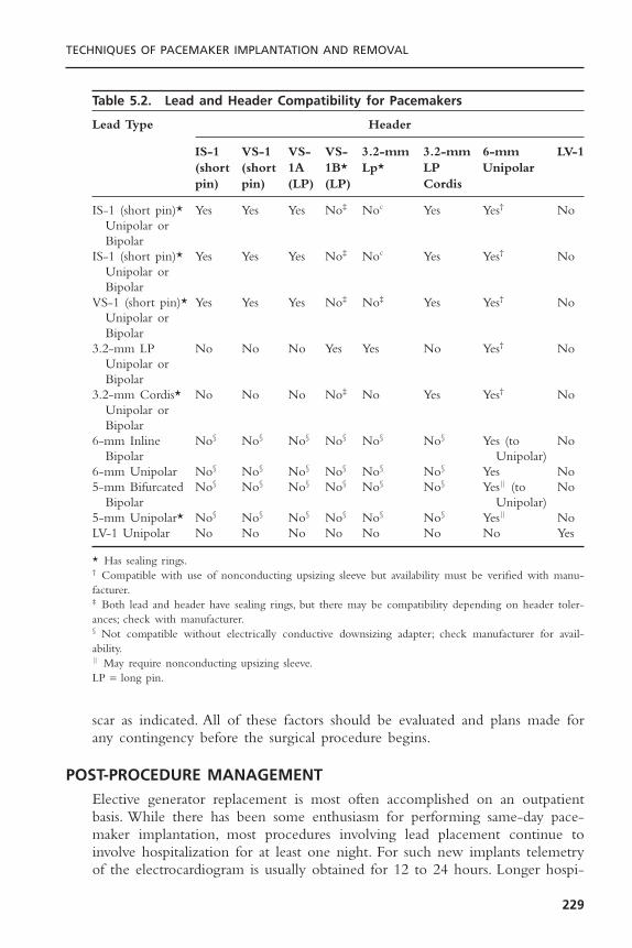
scar as indicated. All of these factors should be evaluated and plans made forany contingency before the surgical procedure begins.
POST-PROCEDURE MANAGEMENTElective generator replacement is most often accomplished on an outpatientbasis. While there has been some enthusiasm for performing same-day pace-maker implantation, most procedures involving lead placement continue toinvolve hospitalization for at least one night. For such new implants telemetryof the electrocardiogram is usually obtained for 12 to 24 hours. Longer hospi-
TECHNIQUES OF PACEMAKER IMPLANTATION AND REMOVAL
229
Table 5.2. Lead and Header Compatibility for Pacemakers
Lead Type Header
IS-1 VS-1 VS- VS- 3.2-mm 3.2-mm 6-mm LV-1(short (short 1A 1B* Lp* LP Unipolarpin) pin) (LP) (LP) Cordis
IS-1 (short pin)* Yes Yes Yes No‡ Noc Yes Yes† NoUnipolar orBipolar
IS-1 (short pin)* Yes Yes Yes No‡ Noc Yes Yes† NoUnipolar orBipolar
VS-1 (short pin)* Yes Yes Yes No‡ No‡ Yes Yes† NoUnipolar orBipolar
3.2-mm LP No No No Yes Yes No Yes† NoUnipolar orBipolar
3.2-mm Cordis* No No No No‡ No Yes Yes† NoUnipolar orBipolar
6-mm Inline No§ No§ No§ No§ No§ No§ Yes (to NoBipolar Unipolar)
6-mm Unipolar No§ No§ No§ No§ No§ No§ Yes No5-mm Bifurcated No§ No§ No§ No§ No§ No§ Yes|| (to No
Bipolar Unipolar)5-mm Unipolar* No§ No§ No§ No§ No§ No§ Yes|| NoLV-1 Unipolar No No No No No No No Yes
* Has sealing rings.† Compatible with use of nonconducting upsizing sleeve but availability must be verified with manu-facturer.‡ Both lead and header have sealing rings, but there may be compatibility depending on header toler-ances; check with manufacturer.§ Not compatible without electrically conductive downsizing adapter; check manufacturer for avail-ability.|| May require nonconducting upsizing sleeve.LP = long pin.

talization may be required because of ancillary medical problems or as a resultof complication.Analgesia may be necessary but it is rarely needed after the firstfew days.The patient is advised to limit motion of the ipsilateral upper extrem-ity for a time—specifically, to avoid raising it above the shoulder level or subjecting it to marked abduction for approximately 2 weeks. Patients shouldnot, however, completely immobilize the arm as this may delay ultimate reha-bilitation. The incision should be kept completely dry for 5 to 7 days.
Before the patient’s discharge, the device is programmed in accordance withthe patient’s specific needs and a complete noninvasive assessment of the pacingsystem is performed. Programming of the pacemaker is guided by two princi-ples: 1) optimization of the patient’s hemodynamic state, and 2) maximal con-servation of battery-energy expenditure. When these two factors are inopposition, the first should rule; however, opportunities to achieve the secondshould not be overlooked.This might include programming a longer AV intervalto avoid fusion beats, a low resting minimal heart rate, and lower stimulationoutputs (within an acceptable safety margin). Rate-adaptive parameters may beset before the patient is discharged or during a follow-up visit. This is com-monly done empirically and is tested by having the patient perform walkingexercises.38 The adequacy of pacing response may be judged by real-time teleme-try or by using rate histograms stored in the pacer. Follow-up evaluation andpossibly adjustment of programmed parameters, including rate adaptation, willbe necessary. An increase in capture threshold over the first 2 to 6 weeks afterimplantation is to be expected with non–steroid-eluting leads, but even ifsteroid-eluting devices are used, an adequate safety margin should be pro-grammed into the generator to ensure successful pacing during this time. Thisis usually achieved with a voltage output of three to five times threshold atimplant. Some of the newer devices have a mechanism for automatic capturethreshold detection. These devices may allow for the programming of a lowerpacing output with the recognition that the unit will increase pacing output ifit detects a rise in threshold. Care should be taken to ensure that these deviceshave acceptable evoked response amplitudes acutely and at follow-up assess-ments. Older patients, interestingly, seem to have less of a rise in threshold overtime presumably because they exhibit less of a reaction to the leads. A copy ofthe programmed parameters should be given to the patient to keep, in additionto the device registry card. Importantly, the implant site should be kept com-pletely dry for 5 to 7 days to reduce the risk of infection.
It is important that the physician register the generator and leads appropri-ately so that the patient may be tracked should recall of a device occur. Arrange-ments for follow-up care must be made by the implanting physician, and the patientshould be counseled as to the importance of having the system checked at regularintervals.There is some controversy as to the need for endocarditis prophylaxis inpatients with endocardial leads. Although there is a potential for infective endo-carditis to occur, this has been reported infrequently and rarely is the offendingorganism oral flora. Most implanters do not routinely recommend antibiotic pro-phylaxis although results of pending studies may change practice in the future.
CARDIAC PACING AND ICDS
230
COMPLICATIONS OF IMPLANTATIONInherent with pacemaker therapy is the potential for the occurrence of an unto-ward event. Skill, experience, and technique are all mitigating factors, but everyoperator should anticipate that eventually he or she will have to deal with a com-plication. Thus, the implanting physician must be concerned not only with mea-sures to avoid complications but also with their recognition and treatment. Suchuntoward events associated with the introduction and physical presence of the gen-erator and lead may be classified according to their etiology (Boxes 5.2 and 5.3).
In the Pacemaker Selection in the Elderly (PASE) study, 6.1% of the 407patients receiving dual chamber pacing systems had a complication of implan-tation.39 There were nine lead dislodgments, eight instances of pneumothorax,and four cardiac perforations. A repeat surgical procedure of some sort wasrequired in 18 (4.4%) of the patients. In a single center study of over 1300 per-manent pacemaker implants reported by Tobin and colleagues,40 complicationswere noted in 4.2% of patients. Lead displacement occurred in 2.4%, significantpneumothorax in 1.5%, pericardial tamponade in 0.2%, and hemothorax leadingto death in one patient (0.08%).The economic consequences of a complicationwere substantial with the average incremental cost of $14,547 for a lead dis-lodgment; $10,052 for a pneumothorax; and $32,472 for a tamponade. Therewas an inverse relationship between the incidence of acute complication andoperator case volume and experience. While the acute implant complicationsassociated with DDD pacing is not different than that with single chamberpacing, the total complication rate associated with dual-chamber pacing overtime is higher than that with VVI or single lead VDD due to the presence ofthe additional lead.41
TECHNIQUES OF PACEMAKER IMPLANTATION AND REMOVAL
231
Box 5.2. Acute Complications of Pacemaker Implantation
1. Venous access• Secondary to Seldinger technique
PneumothoraxHemothoraxOther (e.g., injury to thoracic duct, nerves, etc.)
• Secondary to sheath insertionAir or foreign body embolismPerforation of the heart or central veinInadvertent entry into artery
2. Lead placement• Brady-tachyarrhythmia• Perforation of heart or vein• Damage to heart valve• Damage to lead
3. Generator• Improper or inadequate connection of lead• Pocket hematoma

Although neither elective generator replacement nor upgrading of a VVIsystem to a dual-chamber device is usually considered to be a risky procedure,both are associated with the potential of complication. Harcombe and co-workers found that the rate of late complications (those occurring later than 6weeks after the procedure) was higher for elective replacement (6.5%) than forinitial system implantation (1.4%).42 These were primarily erosion and infectionrelated to the pacemaker pocket.As might be expected, complications were morecommon with inexperienced operators who were relegated to the electivereplacements suggesting that technique as well as physiologic substrate playimportant etiologic roles. Upgrade of a VVI device to a dual chamber or biventricular system carries the potential for all the complications associated withvenous access and lead placement (which may be confounded by the preexisting lead), as well as a slight increase in risk of late pocket infection and skin erosion. Upgrade procedures are often longer in duration than a denovo dual-chamber implantation.43 This may be related to difficulty isolating thegenerator and lead in the pocket due to adhesion formation, difficulty withvenous access, interference with the existing lead, or a combination of thesefactors.
Venous AccessBy its very nature, the blind subclavian venous puncture has a potential for com-plication, the risk of which depends on both operator skill and the patient’s
CARDIAC PACING AND ICDS
232
Box 5.3. Delayed Complications of Pacemaker Therapy
1. Lead-related• Intravascular thrombosis (embolization)• Intravascular constriction (i.e., SVC obstruction)• Macro- or micro-lead dislodgment• Fibrosis at electrode-myocardial interface• Infection—endocarditis• Lead failure
Insulation failure (inner/outer)Conductor fracture
• Retention wire fracture• Chronic perforation• Pericarditis
2. Generator-related• Pain• Erosion• Infection-pocket• Migration• Premature failure• Damage from extrinsic energy (e.g., radiation, electrical shock, etc.)
3. Patient-related• Twiddler syndrome

anatomy. Inadvertent damage by the exploring needle to structures that lie inproximity to the vein (e.g., lung, subclavian artery, thoracic duct, and nerves) isthe most frequent cause of significant complications encountered during theimplantation process. Such complications may be evident immediately, or theymay be recognized only after the procedure has been completed. It has been sug-gested that knowledge of subclavian venous anatomy by digital cinefluoroscopicvenography might be helpful in accessing the vessel and avoiding complication.44
Pneumothorax is often asymptomatic and discovered on the routine post-procedure chest radiograph. Rarely, it may be the cause of severe respiratory distress intraprocedurally. Pleuritic pain, cough (especially if productive of blood-tinged sputum), and difficulty in breathing suggest the diagnosis. The aspirationof air into the syringe during attempted venous puncture may also raise concernabout this possibility, but it has been neither a sensitive nor specific sign. Thepresence of apical cystic lung disease, variations in the relationship between theclavicle and subclavian vein, and an uncooperative (poorly sedated) patient mayincrease the risk for this complication—and repeated unsuccessful attempts atvenous puncture certainly do. Respiratory symptoms arising during the proce-dure should prompt assessment of pulse, blood pressure, oximetry, and perhapsblood gas analysis. Fluoroscopic examination of both lung fields should also beperformed.
Treatment of pneumothorax depends on its severity and associated symptoms. Respiratory distress during the procedure may necessitate the urgent/emergency insertion of a chest tube. The completion of the implantation willdepend on the patient’s status and the progress already made. Although theremay be some controversy as to the need for evacuation of an asymptomaticpneumothorax seen on chest radiograph, if its extent is greater than 10%, a chesttube should be considered. If a small pneumothorax does not resolve or enlargeson serial radiographs, evacuation is indicated. Inspiration of 100% oxygen by face-mask may help shrink a small pneumothorax.
Hemothorax, a less common complication of the subclavian approach,results from injury to the subclavian artery, vein, or other intrathoracic vessel.Penetration of the subclavian artery by the exploring needle is usually not pro-ductive of sequelae if the needle is withdrawn and slight pressure is applied atthe site of entry under the clavicle. Significant complication may occur, however,if the artery is lacerated by the cutting edge of the needle or if a large-boredilator or sheath is inadvertently introduced. If a large sheath is mistakenlyinserted into the artery, it should probably be left in place, pending a promptdefinitive management decision since removal may result in significant bleed-ing. Options include surgical repair; endovascular treatment using a prolongedballoon inflation45 or a stentgraft46; or an attempt at sheath withdrawal withexternal compression. Opinions from an interventional radiologist and a vascu-lar surgeon should be obtained if possible. A quick angiogram may determinewhether an important branch vessel (e.g., internal mammary graft or vertebralartery) is involved or might be excluded by a covered stent. Because of the riskof thrombus formation around the sheath, it should be withdrawn to the
TECHNIQUES OF PACEMAKER IMPLANTATION AND REMOVAL
233
subclavian artery itself to prevent embolization of clot to the cerebrovascularsystem. The likelihood of a bleeding complication is increased if the coagula-tion system is impaired either intrinsically by co-existing disease or by phar-macologic therapy. Angiographic evaluation and possible repair should beconsidered for severe or persistent bleeding from an uncertain source. A symp-tomatic hemothorax should be drained.
Air embolism can occur when a central vein is accessed by a sheath, regard-less of the technique used to introduce it. This complication may be signaledby a hiss as air is sucked into the sheath by negative intrathoracic pressure andmay occur suddenly when a heavily sedated, snoring patient deeply inspires ata time when control over the sheath’s orifice is not adequate. Air may be flu-oroscopically tracked into the right ventricle and pulmonary outflow tract.47 Inmost instances, the amount of air introduced is small and well tolerated, but re-spiratory distress, chest pain, hypotension, and arterial oxygen desaturation mayoccur if there is significant blockage of pulmonary flow. Treatment of symp-tomatic air embolism includes supplemental oxygen, attempted catheter aspira-tion, and inotropic cardiac support if necessary. These supportive measures willusually suffice until the air embolism breaks up and absorption occurs. Posturalchanges to prevent migration of air trapped in the right atrium or ventriclefrom reaching the pulmonary arteries may be considered, although usually thelatter occurs too rapidly for these maneuvers to be of much success. Preventivemeasures are listed in Box 5.4.
Infrequent complications of venous access include laceration of the tho-racic duct leading to chylothorax, and damage to the internal mammary arterywhich may cause acute ischemia when this conduit has been used as a graft.Percutaneous repair has been reported in a case of acute occlusion of the originof a left internal mammary graft caused by compression resulting from pace-maker lead implantation.48
Lead PlacementArrhythmia: The introduction, manipulation, and positioning of the pacemaker
leads in the heart may give rise to a number of complications. Arrhythmia maybe a manifestation of the patient’s underlying disease, or it may be procedurally
CARDIAC PACING AND ICDS
234
Box 5.4. Avoidance of Air Embolism
1. Increase central venous pressure.• Hydrate well.• Elevate legs (Trendelenburg position).• Have patient perform Valsalva maneuver when
sheath is open.2. Awaken patient and caution against deep inspiration.3. Use smallest sheath compatible with task.4. Pinch or occlude neck of sheath when appropriate.5. Consider the use of sheaths with hemostatic valves.

related (Box 5.5). In a pacemaker-dependent patient, accidental interference witha preexisting pacing system—whether temporary or permanent—may causeasystole or symptomatic bradycardia. Other causes of a bradyarrhythmia includea vagal reaction, excessive local anesthesia, and injury to the conduction systemduring lead manipulation (e.g., trauma to the right bundle branch in a patientwith left bundle branch block). The use of transcutaneous pacing and or theadministration of atropine or isoproterenol may be helpful in these situationsuntil a means of effective pacing can be established.
Tachyarrhythmia may also occur during implantation; it is usually the resultof stimulation of myocardium by a lead or guidewire. Supraventricular arrhyth-mias are most likely to occur in patients with atrial enlargement, heart failure,pulmonary disease, or other predisposing conditions such as sick sinus syndrome;they are usually transient. Atrial fibrillation occurring before or during atriallead placement may be problematic in that atrial parameters cannot be testedunless the rhythm terminates either spontaneously or by cardioversion. It hasbeen suggested that an atrial lead may be placed in the presence of atrial fi-brillation occurring at the time of implantation using the criteria of an intra-cardiac fibrillatory amplitude of 1.0mV or greater. This reduces implantationtime compared to the option of intraprocedural cardioversion.49 Ventricular dys-rhythmia is common as the lead is manipulated in this chamber; but it is rarelysustained. Predisposing factors to more malignant arrhythmia include hypoxia,ischemia, pharmacologic therapy (e.g., sympathomimetics), and asynchronouspacing. Removal of the lead from an irritating position almost always termi-nates the ectopy. On occasion a retained guidewire or a temporary ventricularpacing lead is displaced and serves as an occult source of ventricular irritationthat is not resolved by retraction of the permanent pacing lead.
Because the attention of the implanter may be focused on the fluoroscopicimage during lead placement, another individual should be assigned to monitor theECG during this time. Rarely, a permanent ventricular (or prolapsing atrial) pacinglead will be the cause of recurrent ventricular tachycardia post implantation.
TECHNIQUES OF PACEMAKER IMPLANTATION AND REMOVAL
235
Box 5.5. Causes of Arrhythmia during Pacer Implantation
1. Bradyarrhythmia• Patient’s underlying electrophysiologic disorder• Vagal reaction• Lead trauma to the conduction system• Inadvertent disruption of a pacing system• Suppression of escape rhythm by anesthetic
2. Tachyarrhythmia• Atrial/ventricle
Underlying electrophysiologyIrritation by lead/wireIschemia, anesthesia, hypoxia
Perforation: The heart may be perforated internally (into another cardiac chamber)or externally (into the pericardial space) by the pacing lead. Right ventricularperforations are probably more common than reported because clinical sequelaemay not occur. Poor sensing or capture thresholds may prompt withdrawal ofthe lead back into the ventricle with “self-sealing” of the perforation. On occa-sion, however, life-threatening tamponade may occur, and progressive hypoten-sion during or after lead placement should be considered tamponade until provenotherwise by echocardiography. Old age, female gender, steroid therapy, recentright ventricular infarction, and the use of stiff leads (or stylets) may be consid-ered risk factors for perforation. Pericarditis, tamponade, and even pneumotho-rax have been reported as complications caused by active fixation atrial leadplacement due to the helix protruding through the atrial myocardium.50,51
Interference with normal coagulation predisposes the patient to tampon-ade. Anticoagulants should be withheld for at least 8 to 12 hours if there is nosuspicion of perforation, and reinstituted with extreme caution if there is anycause for concern. Thrombolytics should be considered contraindicated in theimmediate postimplant period. If symptoms suggestive of tamponade occurs,echocardiographic confirmation should be obtained unless the condition dictates emergency pericardiocentesis prior to the availability of the ultrasoundequipment. Every effort should be made to obtain an echocardiogram in thelatter situation as soon as possible. Pericardiocentesis with catheter drainage willrapidly reverse the pathophysiology of tamponade and may be the only therapynecessary since the perforation frequently is self-sealing. In some cases tampon-ade may occur with the acute accumulation of only a small amount of peri-cardial fluid. In such cases it may be difficult to access the pericardial space witha needle, necessitating emergency surgical consultation. Less frequently, a moreslowly accumulating effusion may develop over several days as reaction to a relatively small amount of bleeding into the pericardial space. This may followsigns and/or symptoms of pericarditis or present as de novo tamponade. Drainagemay be necessary if hemodynamics are threatened; otherwise, nonsteroidal anti-inflammatory agents may be used and the patient observed over time.
Suspicion of perforation without tamponade may be aroused by an extremedistal location of the lead tip at the cardiac apex (especially if it seems to curvearound the apex, tenting up the cardiac silhouette), or by the presence of a peri-cardial friction rub, chest pain, an ECG-pacing pattern of right bundle branchblock, or an upright unipolar electrogram recorded from the lead tip.52 Poorpacing and sensing thresholds may be seen. In such situations, two-dimensionalechocardiography may be helpful in localizing the lead tip. If perforation is con-firmed, the lead should be withdrawn under hemodynamic monitoring at a timeand facility capable of emergent surgical drainage if necessary.
A transvenous pacing lead may enter the left heart through a communi-cation between the atria, through the membranous septum separating the rightatrium from the left ventricle, or through the muscular intraventricular septum.The permanent pacing lead may also be inadvertently introduced into an arteryand passed retrograde across the aortic valve into the left ventricle. The antero-
CARDIAC PACING AND ICDS
236

posterior radiographic image of a lead positioned in the left ventricle may notbe distinguishable from an image of one placed in the right ventricular apicalposition. Oblique or lateral views, however, will demonstrate the posterior loca-tion of a left ventricular lead (Fig. 5.15). In addition, pacing from the left ventricle will result in a right bundle branch block pattern (see Fig. 5.9).Two-dimensional echocardiography can be used to trace the course of a lead.
Early recognition of a lead in a systemic chamber should prompt its imme-diate repositioning because of the danger of thrombus formation and systemicembolization.53 A review of the literature found that 10 of 27 patients hadthromboembolic complications, including three patients on antiplatelet drugs.54
Options for management of patients with chronically implanted left heart endo-cardial leads include long-term anticoagulation, lead removal at thoracotomy, orpercutaneous lead removal. The latter has been thought to be associated withexcessive risk of systemic embolization but a number of successful procedureshave been reported usually in patients thought to be at increased risk forsurgery.55
Other Lead Complications: Ordinarily, the presence of a pacing lead across thetricuspid orifice results in little or no valvular dysfunction. On occasion,however, this structure may be interfered with or damaged. During insertion,the tines of a passive fixation lead may become entangled with the chordaetendineae, and rupture of the latter may result if vigorous lead withdrawal isattempted. Occasionally, extrication of the lead from the tricuspid apparatus mayrequire use of a locking stylet (with or without extraction sheath) to transmit
TECHNIQUES OF PACEMAKER IMPLANTATION AND REMOVAL
237
Figure 5.15. A: Anteroposterior chest radiograph of a patient after implantation of adual-chamber pacemaker. Right bundle branch pattern was noted on ECG (see Fig. 5.9).The ventricular lead appears to be positioned near the right ventricular apex and theatrial lead appear to be in a suitable position in this view. B: Lateral chest radiographshows a posterior diversion of the ventricular lead at the atrial level. Echocardiographystudies showed evidence of the lead within the left ventricle; and passage of the leadacross a patent foramen ovale, across the mitral valve, and into the left ventricular apexwas confirmed.
A B
the force of traction to the lead tip rather than merely stretching the lead. Thevalve may be chronically injured by the lead’s lying across it; clot and adhesionsmay form between the two and serve as a nidus for infection. Recurrent endo-carditis on a right ventricular lead has been associated with the development oftricuspid stenosis.56
The pacing lead itself may be damaged by the physical forces exerted uponit during the process of implantation, by entrapment by the muscular-skeletalsystem, by retention ligatures, and by the stresses placed on it by the beatingheart. Loss of integrity of the insulation (either inner or outer) is manifested bya low lead impedance that causes a high current drain; conductor fracture isassociated with a high impedance. Lead fracture may be recognized radio-graphically. A defect in the insulation between the conductor wires of a bipolarlead may produce potentials resulting in transient inhibition of the pacemaker.Detection of such intermittent dysfunction may require the performance ofprovocative maneuvers such as raising, abducting, or adducting the ipsilateralupper extremity. Prolonged contact between the conductors can result in a shortcircuit, preventing current from reaching the electrodes and depleting the powersupply. Both lead fracture and loss of insulation integrity can lead to clinicalsymptoms including death in pacemaker-dependent patients.
The most common complication of lead placement is its subsequent dis-placement. This may be obvious on fluoroscopy or radiography (macro-) oraccompanied by no obvious change in position (micro-) and usually occurs early,before clot and fibrosis act to further anchor the device. Dislodgment rates areinversely related to the experience of the implanter, which suggests that inade-quate initial positioning is a major risk factor. A unique cause of lead dislodg-ment is known as Twiddler’s syndrome.57 In these cases, the (usually elderly) patientunwittingly “plays” with the pacemaker in the pocket, turning it in such a waythat the lead(s) are wound around it and, potentially, are withdrawn from theheart (Fig. 5.16).Two other situations in which traction on a lead may result indislodgment relate to the generator. If not sutured to underlying structures, agenerator lying in the subcutaneous tissue may gradually descend through thisspace and pull on the lead. Similarly a “sagging heart syndrome” (postural descentof heart resulting in tension on the lead and displacement) has accompaniedmarked weight loss in morbidly obese patients.58
The incidence of lead dislodgment has been reduced with refinement ofboth active and passive fixation devices; it is now less than 2% or 3%. The riskof this complication is lessened by ensuring a stable position at implant, leavinga proper amount of intravascular lead so that tension is not exerted at the tipby respiration or arm motion, adequately anchoring the suture sleeve to under-lying tissue, and by limiting abduction and elevation of the ipsilateral upperextremity for a time after implantation.
Early recognition of lead dislodgment (often by deterioration in pacingparameters or the occurrence of ectopy) should result in attempts at reposi-tioning. This is usually accomplished with minimal effort because the lead hasnot fibrosed to endocardium or venous endothelium. Deterioration of the
CARDIAC PACING AND ICDS
238

performance of one or more chronic leads may present a more difficult problemand it is often necessary to use a new lead. If exit block is a problem, a shortcourse of steroid therapy may be tried, but more often than not a reposition-ing or insertion of a new lead is necessary. Steroid-eluting leads (including thoseconfigured with an active-fixation mechanism) are beneficial in this regard.
Venous Thrombosis: It should not be surprising that the presence of one or moreintravascular leads may incite thrombosis of the subclavian vein. While asymp-tomatic thrombus appears to be quite common (see subsequent discussion), itsrelationship with the number and type of leads remains controversial. Clinicallysignificant pulmonary embolization is surprisingly rare but may occur. Sympto-matic thrombosis of the brachiocephalic veins occurs on occasion and presentsas a swollen, painful upper extremity, usually within a few weeks of implant.Extension of the clot to involve the innominate vein, superior vena cava,contralateral structures or the cerebral venous sinus may occur. Venography will reveal the extent of thrombus and the state of development of collateralpathways.
Symptomatic thrombosis that is limited to the subclavian or axillary veinsmay be treated conservatively, with heparin acutely and then warfarin for 3 to6 months, or more aggressively with thrombolytic drugs (Fig. 5.17). Throm-bolytic therapy may be given in a large dose for a short time (e.g., 1 millionunits streptokinase during 1 hour) or during 12 to 24 hours (e.g., 200 to
TECHNIQUES OF PACEMAKER IMPLANTATION AND REMOVAL
239
Figure 5.16. Photograph obtained at the time of operative intervention to reposition alead dislodged due to Twiddler’s syndrome. The lead can be seen to be tightly twistedupon itself. Although this tangle can be straightened, the stresses imparted to both theconductor and the insulation make it unsafe to reuse this lead. A new lead should beinserted. (Courtesy of Dr. Paul Levine.)

500,000 units urokinase during 1 hour followed by 100,000 units per hour)with or without concomitant heparin. The newer thrombolytic agents such astissue plasminogen activator and Retavase may also be used.Thrombolytics neednot be delivered directly into an ipsilateral arm vein.
In our experience, thrombolytic therapy has been associated with rapidsymptomatic and angiographic improvement. Prolonged therapy with eitheraspirin or oral anticoagulants may then be considered. We have not observed ableeding complication or clinical recurrence in patients treated in either fashion.Conservative therapy with heat and upper extremity elevation may also be sat-isfactory. This may allow for the development of adequate collateralization.
Silent venous thrombosis is not uncommon; routine venography at the timeof elective generator replacement revealed stenosis in 11% and total occlusionin 12% in 100 asymptomatic patients.59 Duplex sonography showed eitherpathologic changes in the vessel wall (46%) or occlusion (11%) in 56 patients41 months after implant.60 No significant risk factors for thrombosis have beenidentified, although more recently it has been suggested that in patients
CARDIAC PACING AND ICDS
240
Figure 5.17. Venogram 1 week after dual-chamber pacemaker implantation. The patientpresented with swelling and pain in the left arm. Left axillary vein thrombosis is noted.The patient was treated with streptokinase, and a repeat venogram showed restorationof venous patency and disappearance of collateral vessels. (Reproduced by permissionfrom Platia EV, ed. Management of Cardiac Arrhythmias. Philadelphia: JB Lippincott,1987.)
presenting for lead extraction, those with systemic infection are more likely tohave occlusion of the access vein.61 Further evidence supporting the conceptthat venous occlusion may be related to the patient substrate is supplied by Oginosawa and colleages.62 They performed digital subtraction venography beforedevice implantation in 131 patients without symptoms of central venous disease.They found venous obstruction in 14%, half of which had totally occluded veins.Obstruction was more common on the left compared to the right side, 12% vs1.5%. The most common site of obstruction was in the left innominate vessel.Repeat venography was performed a mean of 44 months after pacer implant,at which time 33% of the patients had obstructions, 38% of which were totalocclusions.There were no specific identifiable risk factors either before or afterpacemaker insertion. In most patients, asymptomatic thrombosis becomes aproblem only when attempts are made to reenter the vessel (e.g., for upgradeto a dual-chamber unit). It is not necessary to treat asymptomatic occlusions.Pacemaker leads inserted via the transfemoral route may be associated withfemoroiliac thrombosis and significant pulmonary embolization, necessitatinglead extraction and possibly insertion of an IVC filter.
Complete or partial occlusion of the superior vena cava has been reportedas a complication of pacemakers.63 This has been attributed to both thrombosisand fibrosis and may be treated with balloon dilatation or surgical recon-struction if it becomes symptomatic.Acute or subacute occlusion may be treatedwith anticoagulants and thrombolytic agents. Chronic occlusion is more prob-lematic and is, in general, resistant to pharmacotherapy. In some situations oftotal occlusion of the superior vena cava, endovascular reconstruction may becomplicated by an inability to pass a guidewire through the obstruction. In suchcases it may be possible to remove the existing leads and use the extractionsheath as a means of gaining entrance through the occluded venous system.Dilatation and stenting may then be considered; stenting should not be per-formed over indwelling pacemaker leads. In cases in which endovascular repairis not possible, a surgical approach that enlarges the venous channel with a patchgrafting has been used with some success.
The incidence of lead associated thrombus is uncertain since TEE is usuallyperformed only if there is a clinical indication. Such thrombus in the presenceof infection would be termed a “vegetation.” In general the chance finding ofa clot on a lead does not, in itself mandate therapy; however, if it was very large,consideration would probably be given to anticoagulation. Obviously suchtherapy would be indicated if there is evidence of thromboembolism. A pedun-culated clot on a pacing wire may occlude the tricuspid orifice and cause profound symptoms. Treatment of lead-associated atrial thrombus with throm-bolytic therapy has been reported.64, 65
Generator: The function of a pacing system depends on a proper connectionbetween the leads and the generator. The terminal lead pin(s) are inserted intothe connector block of the generator and are fixed into position by some mech-anism, most commonly set screws. If this is not done properly, the pin may either
TECHNIQUES OF PACEMAKER IMPLANTATION AND REMOVAL
241
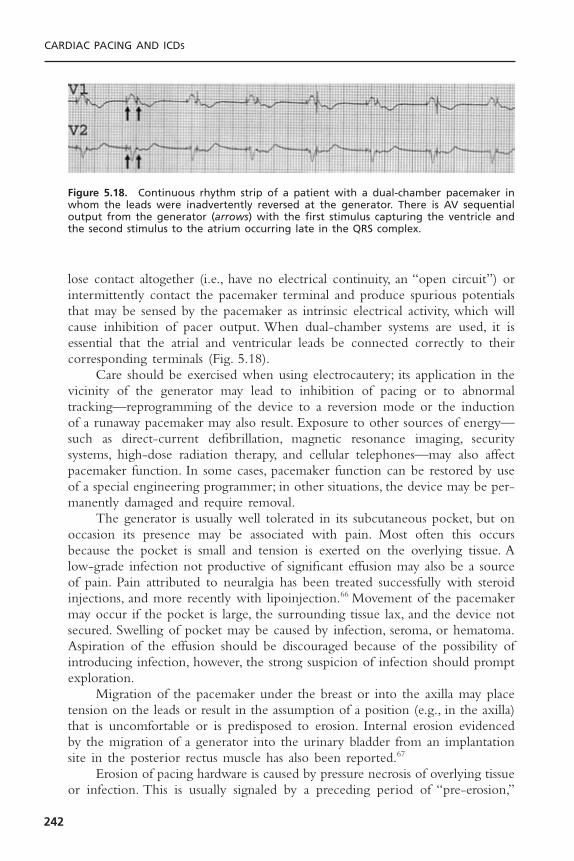
lose contact altogether (i.e., have no electrical continuity, an “open circuit”) orintermittently contact the pacemaker terminal and produce spurious potentialsthat may be sensed by the pacemaker as intrinsic electrical activity, which willcause inhibition of pacer output. When dual-chamber systems are used, it isessential that the atrial and ventricular leads be connected correctly to their corresponding terminals (Fig. 5.18).
Care should be exercised when using electrocautery; its application in thevicinity of the generator may lead to inhibition of pacing or to abnormal tracking—reprogramming of the device to a reversion mode or the inductionof a runaway pacemaker may also result. Exposure to other sources of energy—such as direct-current defibrillation, magnetic resonance imaging, securitysystems, high-dose radiation therapy, and cellular telephones—may also affectpacemaker function. In some cases, pacemaker function can be restored by useof a special engineering programmer; in other situations, the device may be per-manently damaged and require removal.
The generator is usually well tolerated in its subcutaneous pocket, but onoccasion its presence may be associated with pain. Most often this occursbecause the pocket is small and tension is exerted on the overlying tissue. Alow-grade infection not productive of significant effusion may also be a sourceof pain. Pain attributed to neuralgia has been treated successfully with steroidinjections, and more recently with lipoinjection.66 Movement of the pacemakermay occur if the pocket is large, the surrounding tissue lax, and the device notsecured. Swelling of pocket may be caused by infection, seroma, or hematoma.Aspiration of the effusion should be discouraged because of the possibility ofintroducing infection, however, the strong suspicion of infection should promptexploration.
Migration of the pacemaker under the breast or into the axilla may placetension on the leads or result in the assumption of a position (e.g., in the axilla)that is uncomfortable or is predisposed to erosion. Internal erosion evidencedby the migration of a generator into the urinary bladder from an implantationsite in the posterior rectus muscle has also been reported.67
Erosion of pacing hardware is caused by pressure necrosis of overlying tissueor infection. This is usually signaled by a preceding period of “pre-erosion,”
CARDIAC PACING AND ICDS
242
Figure 5.18. Continuous rhythm strip of a patient with a dual-chamber pacemaker inwhom the leads were inadvertently reversed at the generator. There is AV sequentialoutput from the generator (arrows) with the first stimulus capturing the ventricle andthe second stimulus to the atrium occurring late in the QRS complex.
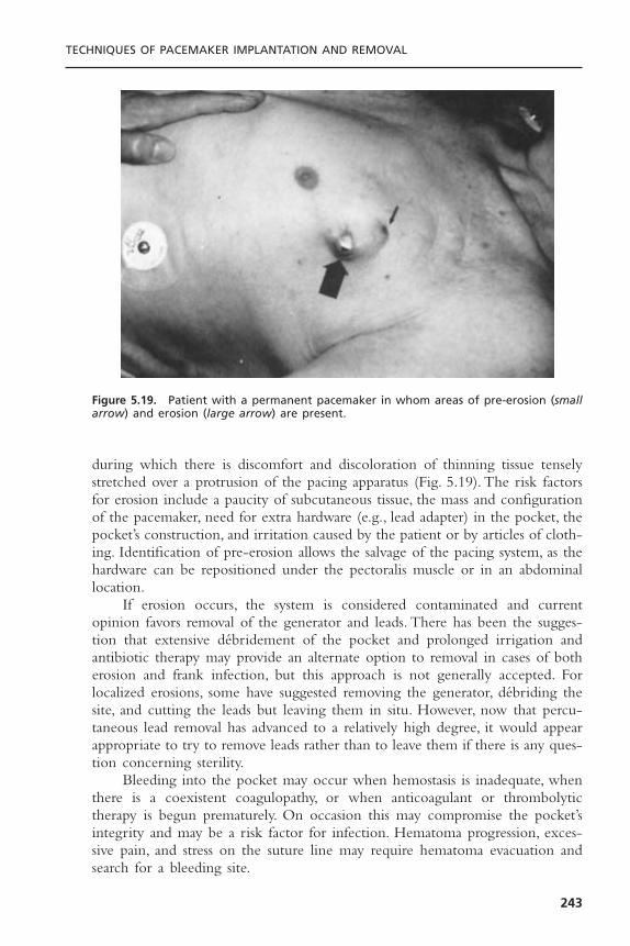
during which there is discomfort and discoloration of thinning tissue tenselystretched over a protrusion of the pacing apparatus (Fig. 5.19). The risk factorsfor erosion include a paucity of subcutaneous tissue, the mass and configurationof the pacemaker, need for extra hardware (e.g., lead adapter) in the pocket, thepocket’s construction, and irritation caused by the patient or by articles of cloth-ing. Identification of pre-erosion allows the salvage of the pacing system, as thehardware can be repositioned under the pectoralis muscle or in an abdominallocation.
If erosion occurs, the system is considered contaminated and currentopinion favors removal of the generator and leads. There has been the sugges-tion that extensive débridement of the pocket and prolonged irrigation andantibiotic therapy may provide an alternate option to removal in cases of botherosion and frank infection, but this approach is not generally accepted. Forlocalized erosions, some have suggested removing the generator, débriding thesite, and cutting the leads but leaving them in situ. However, now that percu-taneous lead removal has advanced to a relatively high degree, it would appearappropriate to try to remove leads rather than to leave them if there is any ques-tion concerning sterility.
Bleeding into the pocket may occur when hemostasis is inadequate, whenthere is a coexistent coagulopathy, or when anticoagulant or thrombolytictherapy is begun prematurely. On occasion this may compromise the pocket’sintegrity and may be a risk factor for infection. Hematoma progression, exces-sive pain, and stress on the suture line may require hematoma evacuation andsearch for a bleeding site.
TECHNIQUES OF PACEMAKER IMPLANTATION AND REMOVAL
243
Figure 5.19. Patient with a permanent pacemaker in whom areas of pre-erosion (smallarrow) and erosion (large arrow) are present.
While not a complication of implantation per se, a generator may prema-turely and without warning fail or may revert to an unsafe pacing mode. Theformer may relate to a defect in the power supply and the latter a function ofunrecognized problems with circuit design. Pacemakers are also subject to elec-tromagnetic interference if the field is strong enough. There is a potential riskof exposing pacemaker patients to magnetic resonance imaging equipment.
InfectionA non-eroded pacemaker implantation site may become infected. Diabetes mel-litus and postoperative hematoma appear to be predisposing factors.68 Acuteinfections (usually with Staphylococcus aureus) become manifest within the firstfew weeks of implantation and are often associated with the accumulation ofpus. A more indolent infection caused by a less virulent agent such as S.epidermidis may present months or years after implantation. A fungal infectionmay also occur in the pocket and present as an indolent process with relativelyscant growth of the organism. Infections with less virulent organisms can presentas a small area of erythema, a pimple-like lesion, or a draining sinus. In somecases they appear as cellulitis or pre-erosions. One-third to one-half of infec-tions complicate new implants; the rest are associated with reoperation for gen-erator replacement or lead repositioning.69 Pocket infections are generallyconsidered to result from organisms introduced from the skin’s surface. Super-ficial infections of the suture line that do not extend to the pocket itself maybe treated conservatively.
Staphylococci and presumably other pathogens, adhere to the plastic insu-lation of pacing hardware and form colonies that become covered with asecreted substance protecting the organism from host defense and antimicrobialdrugs. Antibiotic therapy alone is rarely sufficient to cure these infections, andremoval of the pacing system is usually indicated. In patients with erosions orlocalized pocket infections who have been on antimicrobial therapy and havenegative blood cultures, it may be possible to place a new pacing system at adifferent site at the time of removal of the suspect hardware. Most of the timehowever it would seem prudent to take a two-step approach with temporarypacing (if pacer dependent) used to bridge the time between explantation andnew device implant a few days later. After device removal the infected pocketmay be partially closed and a drain inserted or packed with wet-to-dry dress-ings and left open to heal by secondary intention.
Less frequently, a pacemaker patient may develop sepsis without localizingsigns, in which case endocarditis associated with a pacing lead should beexcluded. Lead endocarditis generally occurs later than pocket infection. It maybe related to an organism introduced at implantation but is more often thoughtto be secondary to a transient bacteremia often from an undefined source. Thediagnosis of lead endocarditis is made when a vegetation is detected by ultrasound. In the absence of a positive transthoracic echocardiogram a trans-esophageal is necessary to rule the diagnosis in or out. A recent report suggestspacemaker associated endocarditis constitutes 4.6% of the entire population with
CARDIAC PACING AND ICDS
244
infective endocarditis and occurs with an incidence of about 0.6% in pacerrecipients. Staphylococci species predominate with about two-thirds being coag-ulase negative.70
The presence of a vegetation should mandate the removal of all pacinghardware after antibiotics have been started. In these situations, time betweenexplant and implantation of a new permanent system is necessary for antibiotictherapy to sterilize the blood. Generally this interval is related to the durationof previous antibiotic treatment and the confirmation of negative blood cul-tures, usually 3 to 10 days. Patients are usually capable of being discharged there-after on continued antibiotics. The antibiotic therapy is selected on the basis ofthe organism cultured from the blood or hardware, and treatment durationshould be similar to that of non–pacemaker associated infective endocarditis withthe same organism.
In the absences of a positive echocardiogram, a first episode of sepsiswithout an identifying cause should be treated with antibiotics and the pacingsystem retained. A recurrence of sepsis after a course of antibiotic therapy in apatient without a demonstrable etiology should prompt consideration of removalof the entire pacing system even if there is no clinical evidence that the leadsor generator are infected.
Complications of Biventricular PacingImplantation of a coronary venous lead is the major procedural differencebetween biventricular and simple dual-chamber pacemaking. It is subject to allthe complications associated with dual-chamber systems plus those unique toleft ventricular pacing.71 The left ventricular lead must be placed in a lateral wallvein that has been a challenge especially in the early experience with this modality.Inability to achieve a left ventricular lead placement by a transvenous approachhas been reported to be as high as 9%. Unique complications include extensivecoronary sinus dissection (4% to 7%) and coronary venous perforation (2%).Thelatter may lead to tamponade requiring urgent drainage. With better tools andmore experience lead placement has been facilitated and the long proceduretimes as well as the significant complication rate reduced. Extracardiac stimula-tion from the left ventricular lead (diaphragm and phrenic nerve) may also beproblematic and should be tested for at the time of implant. Its occurrenceshould prompt search for another lead implant site. Appropriate programmingof these devices is a concern since the patient population is hemodynamicallyfragile and sensitive to changes in the A-V interval.
Lead ExtractionGeneral Principles: On occasion, consideration is given to the removal of
implanted endocardial leads (Box 5.6). The ease of accomplishing this task andthe risk associated with lead removal is related to the time the lead has beenimplanted. Thus, a lead that has been in place for 3 months or less should beeasily removed whereas one in place for longer than a year may well presentdifficulties due to fibrosis, which may occur at any of a number of sites in the
TECHNIQUES OF PACEMAKER IMPLANTATION AND REMOVAL
245

heart and central veins, which the lead had contact with. Non-isodiametric leadsand those with anchoring appendages (tines or fins) present additional prob-lems. When we speak of lead extraction we are generally concerned with thespecial challenges presented by a chronically implanted lead, i.e., one with animplant duration greater than 1 year. This definition may also be used in situ-ations in which specialized tools (e.g., sheaths, locking stylets, snares, etc.) areneeded and/or when the lead is removed from a site other than that of origi-nal venous access.The term “lead explant” is used for the removal of leads havingan implant duration of less than 1 year with only the tools used in a typicalimplantation and manual traction. These definitions have some importance interms of the requisite qualifications of physicians performing the respective pro-cedures (see subsequent discussion).72 While most of this discussion is directedat lead “extraction,” it is relevant to physicians performing lead “explantation”as well.
There are two general approaches for the removal of pacing leads: percu-taneous or transthoracic. Most pacing physicians think that if extraction is to beperformed it should be done percutaneously; others however may still argue thebenefits of surgery as a primary approach. Certainly simple traction on the leadis easy, straightforward, and logistically undemanding. If all leads would yield to
CARDIAC PACING AND ICDS
246
Box 5.6. Indications for Lead Extraction
Class ISepsis (including endocarditis) involving the pacing systemLife-threatening arrhythmias due to retained lead fragmentRetained lead or fragment that poses imminent physical threat to patientClinically significant thromboembolic event caused by a lead or lead fragmentOcclusion of all useable veins with need to implant a new pacer systemLead that interferes with the operation of another device
Class IILocalized pocket infection or erosion that does not involve transvenous portion of
leads when lead can be separated from infected areaOccult infection with no clear source but pacer system suspectedChronic pain at pocket or lead insertion sites unresponsive to other managementLead failure or design flaw that may pose a future risk to the patientLead that interferes with treatment of a malignancyLeads preventing vascular access for new implantable deviceNonfunctional lead in a young patient
Class IIIRisk of lead removal significantly higher than benefitSingle nonfunctional lead in older patientNormally functioning lead that may be reused at the time of generator replacement

this treatment there would be little debate as to the threshold for lead extrac-tion and even less support for the more invasive surgical option. Unfortunately,chronic leads are not so readily removed and, even with the variety of toolsavailable to assist us in the percutaneous technique, the procedures may be long,difficult, and associated with a finite mortality and a significant morbidity.
The risks of lead removal correctly influence the aggressiveness with whichone should pursue this approach. Postmortem pathologic studies of the heartsof patients with permanent pacemakers have revealed intense fibrosis and encap-sulation, especially involving the ventricular portion of the lead. This includesthe tricuspid valve and its supporting apparatus. Attempts to remove these leadsex vivo are associated with myocardial avulsion, valve damage, and disruption ofthe lead.73 Implants of longer duration tend to have more extensive fibrosis, butwe have observed significant encapsulation of an atrial lead at post mortemexamination 6 weeks after implantation.
Contemporary leads used in the United States are of low profile and pri-marily coaxial bipolar in configuration; they do not, in general, tolerate the phys-ical forces that may be necessary to extract them by simple traction in thepresence of significant fibrosis. Thus, a great variety of tools have been devel-oped to facilitate the extraction of these devices via the process of counter-traction. These include a stylet that “locks” in the distal lead, and sheaths thatare passed over the lead body, stripping it of fibrous attachments.
The specific events that might complicate lead extraction pertain to thephysical forces used to strip away fibrous adhesions to the lead body, and thoseused to extricate the tip of the lead from the heart. Catastrophic events, whenthey occur, usually result from either a laceration of a central vein by an extrac-tion tool or perforation of the heart at the site of tip fixation. Embolization ofa large vegetation to the pulmonary artery may also cause death. Damage tothe tricuspid valve, or embolization of lead fragment or clot to the lung or,through a patent foramen ovale to the systemic circulation, may also occur.While most complications become evident during or shortly after the extrac-tion procedure, some such as a retroperitoneal bleed, pulmonary embolism, orpericardial tamponade may be delayed in presentation. Because of the risksinvolved it is essential that an adequate informed consent be obtained from thepatient and that the reasons for performing lead extraction, the potential risksand benefits, and alternatives are thoroughly discussed with the patient andfamily by the operator.
IndicationsLead extraction has inherent risks, thus the decision to undertake the proceduremust be weighed against the risk of not extracting the lead. Indications for leadremoval based on the latter have been classified in the ACC/AHA guidelineformat as: class I, general agreement for removal; class II, situations in whichleads are often removed but with some divergence of opinion; class III, generalagreement that removal is unnecessary.72 This classification primarily addresses
TECHNIQUES OF PACEMAKER IMPLANTATION AND REMOVAL
247
the nature of the risk to the patient of not removing a lead, but it does not approach the risk of extracting a chronically implanted lead in a specificpatient.Thus, an infected lead is often surprisingly easy to remove, whereas elec-tive removal of a nonfunctioning passive-fixation lead in place for a number ofyears may be extremely difficult and result in complications. A number of mod-ifying factors based on clinical parameters thought to influence the risk of leadextraction have been included in the indication guidelines for the extractingphysician to consider.These parameters relate to the patient (age, gender, overallhealth); anatomy (presence of calcification and vegetations associated with thelead); lead (number of leads, their construction and condition); operator (physi-cian training, experience, and case volume); and the wishes of the patient.Thesefactors are not absolutes but rather supply a context in which to assess the risksfor each specific situation and weigh these against the perceived benefit ofextraction. Their consideration may be especially important for class II indica-tions for which the clinical necessity of removal may be debated.
An infected lead heads all hierarchical classifications of indications for leadremoval, whereas retained nonfunctioning hardware is the least aggressivelypursued.The latter poses little risk to the patient74 but may complicate the place-ment of additional pacing leads either by adding to the venous obstruction (andthe risk of thrombosis/embolization) or by generation of spurious electricalpotentials between leads. Rarely a functionless retained lead may, if not prop-erly sutured down in the pacer pocket, retract into the venous system andmigrate into the heart, pulmonary artery, or even into the left heart via a patentforamen ovale. The likelihood of any of the latter is small and the routineremoval of superfluous noninfected leads probably forms the dividing linebetween the aggressive lead extractor and those who are more conservative.
Lead failure is almost always defined in terms of electrical performance(e.g., ability to pace and or sense appropriately; or impedance changes suggest-ing insulation or conductor failure).The danger to the patient is not due to thephysical presence of the lead but to the potential inability of the device to doits job. In these cases, removal of the problem lead is of much less concern thanthe insertion of a new device with normal electrical function. There are leads,however, which may exhibit normal electrical function but offer a physical riskto the patient. The Accufix J lead presents a unique risk to the patient in thata small metal wire placed within the lead only to maintain a J shape is subjectto fracture under the stress and strain of clinical use. The fractured ends maywear through the insulation and potentially perforate the heart causing cardiactamponade or mediastinal hemorrhage. In this situation of “lead failure,” elec-trical function is normal but the physical presence of the lead places the patientat risk. Alleviation of this risk at the time of recognition of the problem wouldhave required lead extraction in the some 45,000 patients in whom the devicewas implanted. A critical concern for those suggesting guidelines for patientmanagement is whether the risk of lead extraction is less than the mortality andmorbidity from the Accufix J lead itself. Indeed a registry established to studythis issue concluded that the risk of death from elective lead extraction of non-
CARDIAC PACING AND ICDS
248

fractured leads is higher than the risk of injury from the lead.75 This informa-tion has resulted in a recommendation of conservative management of thesepatients with periodic cinefluoroscopy to screen for retention wire fracture. Iffracture occurs options include removal of the lead itself or snaring of the pro-truding wire fragment using a percutaneous catheter technique.
RisksLead extraction using modern tools was associated with a 0.6% risk of deathand a 2.5% risk of potentially life-threatening complications in the multicenterCook Extraction Registry.76 The same group subsequently found a lower riskof death and major complication (0.04% and 1.4%, respectively), attributed toincreasing experience, with no deaths reported by high volume operators.77 Riskof a major complication was associated with the female gender and number ofleads in place while risk of any complication was related to less experiencedoperators (<50 procedures). The risk of death may have been understated bythis registry since the Accufix J lead registry75 (which was contemporaneouswith the former) revealed a 0.4% risk of death. The availability of new extrac-tion tools, such as the laser sheath, has facilitated the extraction procedure andthe overall success rate, but has not reduced complications. A recent multicenterreport of the use of the laser sheath in the removal of over 2500 leads revealedan in-hospital death rate of 0.8%.78 Extraction of any chronically implanted leadshould be undertaken only after careful consideration of the risk-benefit ratioincluding patient age, overall health, presence of calcification or vegetationsinvolving the leads, duration of implant, and patient preference to assume addi-tional risk.
TECHNIQUEExtraction of chronically implanted endocardial leads should only be undertakenby experienced physicians and surgeons skilled in the required techniques.Unfortunately this procedure is not frequently performed and there are fewopportunities even in fellowship programs to receive adequate formal training.Acknowledging the well documented association with complications and in-experienced operators, guidelines for the qualification of physicians have beenproposed.2,72 The performance of a minimum of 20 procedures under the super-vision of an experienced (more than 100 procedures) operator is recommendedbefore independent practice of these techniques.
The extraction process begins with the gathering and collating of knowl-edge about the patient and implanted system (Box 5.7) from the patient’s historyand medical records. This may be augmented from information from the man-ufacturers of the implanted devices. A chest radiograph is recommended beforethe procedure to exclude the presence of undocumented hardware. Recent lab-oratory data, such as complete blood cell count, platelet count, INR and aPTT,electrolytes, BUN, creatinine, and basic chemistries, should be confirmed accept-able. Blood should be typed and cross-matched. It is necessary to know if
TECHNIQUES OF PACEMAKER IMPLANTATION AND REMOVAL
249
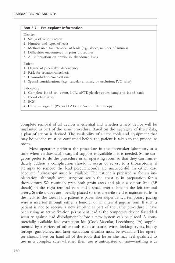
complete removal of all devices is essential and whether a new device will beimplanted as part of the same procedure. Based on the aggregate of these data,a plan of action is devised. The availability of all the tools and equipment thatmay be needed must be confirmed before the patient is taken to the procedureroom.
Most operators perform the procedure in the pacemaker laboratory at atime when cardiovascular surgical support is available if it is needed. Some sur-geons prefer to do the procedure in an operating room so that they can imme-diately address a complication should it occur or revert to a thoracotomy ifattempts to remove the lead percutaneously are unsuccessful. In either case adequate fluoroscopy must be available. The patient is prepared as for an im-plantation, although some surgeons scrub the chest as in preparation for a thoracotomy. We routinely prep both groin areas and place a venous line (6Fsheath) in the right femoral vein and a small arterial line in the left femoralartery. Sterile drapes are liberally placed so that a sterile field is maintained fromthe neck to the toes. If the patient is pacemaker-dependent, a temporary pacingwire is inserted through either a femoral or an internal jugular vein. If such apatient is not to receive a new implant as part of the same procedure I havebeen using an active fixation permanent lead as the temporary device for addedsecurity against lead dislodgment before a new system can be placed. A com-mercially available lead-extraction kit (Cook Vascular, Leechburg, PA) supple-mented by a variety of other tools (such as snares, wires, locking stylets, biopsyforceps, guidewires, and laser extraction sheaths) must be available. The opera-tor should have on hand all of the tools that he or she may feel qualified touse in a complex case, whether their use is anticipated or not—nothing is as
CARDIAC PACING AND ICDS
250
Box 5.7. Pre-explant Information
Device:1. Site(s) of venous access2. Number and types of leads3. Method used for retention of leads (e.g., sleeve, number of sutures)4. Difficulties encountered in prior procedures5. All information on previously abandoned leads
Patient:1. Degree of pacemaker dependency2. Risk for sedation/anesthesia3. Co-morbidities/medications4. Special considerations (e.g., vascular anomaly or occlusion; IVC filter)
Laboratory:1. Complete blood cell count, INR, aPTT, platelet count, sample to blood bank2. Blood chemistries3. ECG4. Chest radiograph (PA and LAT) and/or lead fluoroscopy
frustrating as to be lacking the tool that might turn a failed procedure into asuccessful one. A pericardiocentesis tray should be readily available and anechocardiography machine should be accessible.The operator must have a step-by-step approach to the specific problems offered by the case in mind, andalways be prepared to meet exigencies as they might arise.
The pocket is usually entered through the previous incision line althoughthis may be altered to include a site of erosion. With a combination of sharpand blunt dissection, the generator and lead(s) are freed. Electrocautery isextremely helpful in freeing leads that are often extensively fibrosed to them-selves and subcutaneous tissue.The lead is traced to the venous entry point, thesuture sleeve is identified, and all retention sutures are cut. The lead is discon-nected from the generator and its internal integrity is accessed by passing aroutine stylet to the tip. In all cases an initial attempt at gentle traction is prob-ably worthwhile, but care must be taken not to damage the lead during thisprocess.
Passive leads are usually more difficult to extract than active leads presum-ably because the appendages incorporated on the former devices provide agreater surface area for fibrous adhesion. It is necessary to attempt to unscrewan active fixation lead before removal. If the retraction mechanism is not effective (or if this is a non-retractable helix) an attempt should be made torotate the entire lead counterclockwise to unscrew the tip from the heart. Thismay be impossible in situations where the body of the lead is extensivelyfibrosed to the heart and veins. In this case stripping the lead with telescopingextraction sheaths prior to rotation of the lead may be of help. Pulling out sucha lead without retracting the helix, especially when in an atrial position mayresult in the removal of a full thickness plug of myocardium and a pericardialbleed.
TOOLS FOR EXTRACTIONThe Superior Approach
If a lead is not easily removable by gentle traction, the stylet should be with-drawn and the lead cut close to the terminal pin with lead cutter. Care mustbe taken not to damage the distal lead, which may be held by a speciallydesigned soft clamp. The central lumen of the lead is identified and carefullydilated with a coil-expander tool. The diameter of the lumen is then deter-mined by the insertion of a series of gauge pins. A locking stylet (Fig. 5.20) ofa size corresponding to the largest gauge pin accepted by the lead is thenadvanced through the lumen to the lead tip.This device is essential to focus theforce of traction as close to the lead tip as possible. There are now a numberof types of locking stylets available, which vary in the way they grip the innercore of the lead. Because current generations of these devices have a greaterflexibility in adapting to a range of inner-core diameters, fewer different typesand sizes need to be stocked. The operator however needs to be familiar withthe specific directions for each of the locking stylets he uses. It may be
TECHNIQUES OF PACEMAKER IMPLANTATION AND REMOVAL
251

difficult or impossible to reverse the locking mechanism and remove thesedevices once they are inserted into the lead. In patients with inner conductorfailure, the inner lumen of the lead may be interrupted, making it impossibleto pass a locking stylet. In this case the femoral approach may be required.
A variety of plastic and metal dilating sheaths (both “powered” by laser orcautery or unpowered) are available to advance over the lead body and free itfrom fibrous adhesions.These dilating devices have been used coaxially in a tele-scoping fashion to provide support and allow for a slightly larger device to beused when necessary. In many cases, applying considerable force and torque tothe sheath is necessary to separate the lead from fibrous adhesions.To minimizethe risk of perforation by the stiff sheaths, fluoroscopic monitoring must be usedto ensure that the proper alignment of the dilator sheath and the lead is main-tained. Traction upon the lead via the locking stylet facilitates the processes.Correct positioning of the sheath near the tip of the lead provides a mecha-nism for countertraction to be applied to the lead to facilitate extraction. By
CARDIAC PACING AND ICDS
252
Figure 5.20. Locking stylets for lead extraction. Three types are shown. Top: The Wilkoffstylet (Cook Vascular, Leechburg, Penn.) has a sliding distal segment that retracts to forman angulated barb that binds to the lumen of the lead at its tip. Middle: The Cook stylet(Cook Vascular) has a small wire “whisker” wound at the tip that unravels and binds thelumen when the stylet is rotated counterclockwise in the lead. Bottom: The Spectranet-ics stylet (Spectranetics, Colorado Springs, CO) has an expandable mesh over the styletbody that when expanded binds the lumen of the lead along its length. Shown here themesh is fully expanded. With the mesh retracted, the entire length of the stylet is iso-diametric with the stylet tip for insertion.

advancing the outer sheath to the lead tip at the endocardial surface, the sheathpins the myocardium in place and allows traction on the lead without invagi-nating or tearing the myocardium (Fig. 5.21).
If the lead(s) are removed successfully, a new pacing system may beimplanted at the same site (if circumstances permit) by using a guidewireinserted through the extraction sheath to facilitate venous entry.This techniqueallows access through even chronically occluded veins.
The process of lead extraction with the use of early generation tools islabor intensive and time consuming: Complete removal of a lead was achieved81% to 87% of the time and inability to remove the lead was encountered in6% to 7% of cases.76 The evolution of technology and introduction of theexcimer laser sheath has greatly facilitated lead extraction by the superiorapproach (see Fig. 5.21). The latter device has optical fibers arrayed circumfer-entially in the lining of the sheath, which is attached to the Spectraneticsexcimer laser generator (Spectranetics Colorado Springs, CO). Laser energyablates the fibrous adhesions as the sheath is advanced. Complete removal ofleads using this approach may be anticipated 90% of patients and partial removalin another 3%.78 An electrosurgical cutting sheath is also available for lead extrac-tion. This device is less expensive but may not be as effective in the more dif-ficult cases as is the laser although there are no adequate comparison trials. Itshould be re-emphasized that neither of these adjunct energy devices haveincreased the safety of lead extraction.
Femoral ApproachOn occasion, a lead cannot be removed from its original venous access site usingthe techniques described above due to inadequate lead remnant in the pocketor inability to pass a locking stylet. In these cases the femoral venous approachis often successful. With this method, a large (16F) sheath with a hemostaticvalve is used as a “workstation” through which any of a number of devicesdesigned to grasp the lead body may be introduced.These devices may includesmaller sheaths, a Dotter retrieval basket, a tip-deflecting guidewire, a “Needle’seye” device (all Cook Vascular, Leechburg, PA), or a variety of other catheters,snares, and bioptomes (see Fig. 5.21). With the femoral technique, one mustgrasp the lead body which can be done with a single device (the Needle’s eyesnare) or with two devices such as a tip deflecting wire and an Amplatz goose-neck snare.The Needle’s eye device is contained in a 12F sheath.There are twoindependently moving mechanisms that can be advanced from the sheath: ahook shaped wire loop (needle’s eye) and a more narrow “threader,” which isdesigned to pass within the hook of the needle’s eye. The goal is to place thedevice so that the lead body is trapped between the needle’s eye and threader.This is usually accomplished by first placing the sheath in the low right atriumwith the devices retained inside.The needle’s eye is advanced out of the sheathand rotated so that it “hooks” around a lead body.The threader is then advancedso that it passes through the distal portion of the needle’s eye such that the lead is between the devices (Fig. 5.22). The sheath is then advanced over the
TECHNIQUES OF PACEMAKER IMPLANTATION AND REMOVAL
253
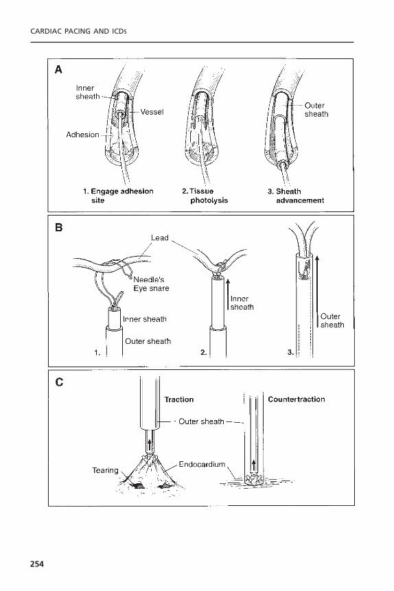
CARDIAC PACING AND ICDS
254

TECHNIQUES OF PACEMAKER IMPLANTATION AND REMOVAL
255
Figure 5.21. Basic techniques of lead extraction. A: Lead extraction from the superiorapproach using the Spectranetics laser sheath apparatus. As the telescoping sheath appa-ratus encounters fibrous adhesions, the inner end-firing laser sheath is used to lyse thefibrosis. The larger outer sheath may then be advanced to apply countertraction at thelead tip. B: Lead extraction from the femoral approach using the Cook IntravascularNeedle’s Eye Snare apparatus. The snare is deployed from telescoping sheaths in thefemoral vein. The lead is entrapped in the snare and then secured against the innersheath. The larger outer sheath may then be advanced to apply countertraction at thelead tip. C: The concept of countertraction is illustrated. When unmodified traction isapplied to the lead, the heart wall may invaginate and tear the myocardium around thelead tip. Using countertraction, the outer sheath holds the myocardium in place, thusminimizing deformity and tearing of the myocardium.
_______________________________________________________________�
Figure 5.22. Fluoroscopic images of ventricular lead extraction by the femoral approach.A: The ventricular lead has been captured with the Needle’s eye snare apparatus at thepoint of the arrow and the redundancy of the lead retracted into the low atrium. B: With traction the lead tip is dislodged from the ventricle and the folded lead body is withdrawn into the large outer sheath. C: The completely extracted lead.
ensemble fixing the captured lead. Once this is accomplished the proximal leadis cut near its original insertion site and traction applied by the sheath pullingthe proximal lead into the heart. The captured lead may be prolapsed into theworkstation, which can be used as a countertraction device as it is advancedover the distal lead; this however may not be feasible with many larger leads.In the latter instance just withdrawing the proximal free end of the lead intothe heart or IVC and then disengaging the Needle’s eye, will allow it to becaptured by a gooseneck snare and more easily removed through the worksta-tion.The workstation may be advanced over the lead into the ventricle to supplycountertraction if necessary.The Needle’s eye technique has been found safe andeffective with a complete extraction success rate of 87% in a population thatincluded patients who had failed prior extraction from the cephalic approach.79
A similar procedure may be performed with a deflecting wire and snare. In thissituation both the wire and snare are situated in the right atrium through theworkstation.A “J” curve is placed on the deflector wire, which is used to “catch”the lead body.The snare is then advanced to tightly grasp the tip of the deflect-ing wire. This effectively forms a loop around the lead body, which can act toretract the lead after the proximal portion is cut from the original access site.Once captured, the lead can be removed as described previously for the Needle’seye device.
While it is always best to withdraw the lead through the workstation, thereare times when this cannot be done and the workstation has to be removedwith the lead inside.This could be a problem if there is more than one lead tobe removed. In such situations we sometimes leave a “buddy” wire in the femoralvein at the time of original access. This allows us to re-enter the same entrysite with a second workstation if it has been necessary to remove the first. Onceall of the leads are out it is safe to remove the workstation and apply manualpressure to the femoral access site for hemostasis.
The femoral workstation technique appears to be reasonably safe (perhapssafer than the superior approach outlined previously) and quite successful. Itavoids having to free up adhesions in the central veins because the proximallead is usually more easily pulled through fibrous sheath from below. On occa-sion however the proximal lead appears trapped within the subclavian vein andwill not yield to femoral traction. In these cases the laser sheath can be veryhelpful in freeing up the proximal lead allowing it then to be extracted via thefemoral workstation. The workstation has a large lumen and blood in it easilyclots; if care is not taken a large thrombus may form and be pushed into thecirculation during the manipulation of devices through the sheath.We routinelyattach a pressurized continuous flush to the sidearm of the device to helpprevent thrombus formation.
Variations on the femoral approach include a hybrid procedure in whichthe femoral workstation is used as described above to pull the proximal leadinto the heart. At this point a snare introduced from the internal jugular veinis used to catch the free end of the lead and pull it out using countertractionfrom a long sheath placed in the internal jugular. The entire procedure might
CARDIAC PACING AND ICDS
256

be performed using an internal jugular approach which has been favored bysome since the direction of force exerted during countertraction is parallel tothe course of the lead.
Accufix Wire Fragment RetrievalAs noted previously, fracture of the “J” retention wire in the Accufix family ofatrial leads may produce protrusion of a wire fragment (Fig. 5.23), which hasthe potential to lacerate the heart and other mediastinal structures. It may bepossible to selectively retrieve the protruding fragment if it is the distal portionof the proximal part of the wire. This is achieved using an Amplatz goosenecksnare passed through an 8F coronary guide catheter of a shape matching thespecifics of the case. Since the proximal portion of the retention wire lies freeunder the outer insulation of the lead, traction on its protruding end results inthe fragment’s removal from the lead into the guide catheter without disrupt-ing the lead itself. Detection of a protruding fragment (so-called class III frac-ture) by screening fluoroscopy should prompt consideration of this form oftherapy as an option to lead extraction.80
TECHNIQUES OF PACEMAKER IMPLANTATION AND REMOVAL
257
Figure 5.23. Cinefluoroscopy of the Telectronics Pacing Systems model 330–801 Accufixatrial J lead. This right anterior oblique projection shows the protruding segment of theretention wire fragment (arrow).
Extraction of Coronary Venous LeadsWith the increased use of biventricular pacing, there has been some concernthat removal of chronically implanted leads from the coronary venous systemwill be associated with high complication rates because of the risk of disrup-tion of the thin-walled coronary veins. While there is limited experience thusfar, removal of these devices has not been associated with complication. Thishowever includes only a very small number of leads with long implant duration.81
Thoracotomy for Lead ExtractionThere has been a natural reticence even among surgeons to remove leads atthoracotomy.While there is no randomized data comparing the two techniques,the Accufix experience suggests no clinically significant difference in the inci-dence of death or major complications. This is not surprising considering theadvanced age and co-morbidity of many pacemaker patients. Surgery howevermay be the only alternative in situations in which percutaneous techniques havefailed and there is an absolute indication for lead removal.
Lead AbandonmentThe alternative to extraction is lead abandonment and (usually) insertion of anew lead. This is not an option in cases of infection where failure to removeall hardware results in an unacceptable risk of re-infection despite vigorous treat-ment with antibiotics. One may abandon the lead by detaching it from the gen-erator and applying an insulating cap to the connector pin. The lead may thenbe placed under the generator or elsewhere in the pocket reserving an optionfor future use in some situations as well as lead extraction should that provenecessary (e.g., the occurrence of infection). Many operators now prefer to cutthe lead and electrically isolate it by pulling the insulation over the exposed endand tying a ligature tightly around the insulation cuff. The lead is then suturedto the underlying tissue to prevent its retraction into the vascular space. Enoughlead is left in the pocket to allow for future extraction if that proves necessary.Active fixation leads however should not be cut because this precludes retrac-tion of the helix of the lead if extraction should ever be needed.
MEDICAL-LEGAL ASPECTS OF IMPLANTATIONAs with many invasive procedures, the patient’s expectations for pacemakertherapy may exceed the results obtained. As noted above, there is ample oppor-tunity for even the most skilled and experienced operator to encounter a mis-adventure. The risk of litigation82 is real and may be focused on any of severalareas of physician responsibility (Box 5.8). Avoiding litigation requires not onlythat the highest of standards be maintained but also that a rapport be establishedwith the patient and the patient’s family.
The best defense against successful litigation is full documentation in thepatient’s medical record of every aspect of the implantation (or extraction)
CARDIAC PACING AND ICDS
258
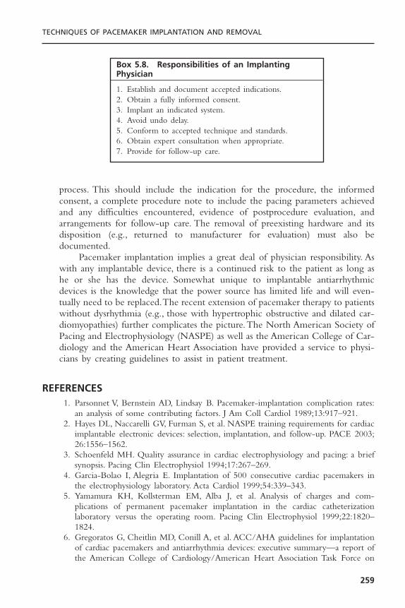
process. This should include the indication for the procedure, the informedconsent, a complete procedure note to include the pacing parameters achievedand any difficulties encountered, evidence of postprocedure evaluation, andarrangements for follow-up care. The removal of preexisting hardware and itsdisposition (e.g., returned to manufacturer for evaluation) must also be documented.
Pacemaker implantation implies a great deal of physician responsibility. Aswith any implantable device, there is a continued risk to the patient as long ashe or she has the device. Somewhat unique to implantable antiarrhythmicdevices is the knowledge that the power source has limited life and will even-tually need to be replaced.The recent extension of pacemaker therapy to patientswithout dysrhythmia (e.g., those with hypertrophic obstructive and dilated car-diomyopathies) further complicates the picture.The North American Society ofPacing and Electrophysiology (NASPE) as well as the American College of Car-diology and the American Heart Association have provided a service to physi-cians by creating guidelines to assist in patient treatment.
REFERENCES1. Parsonnet V, Bernstein AD, Lindsay B. Pacemaker-implantation complication rates:
an analysis of some contributing factors. J Am Coll Cardiol 1989;13:917–921.2. Hayes DL, Naccarelli GV, Furman S, et al. NASPE training requirements for cardiac
implantable electronic devices: selection, implantation, and follow-up. PACE 2003;26:1556–1562.
3. Schoenfeld MH. Quality assurance in cardiac electrophysiology and pacing: a briefsynopsis. Pacing Clin Electrophysiol 1994;17:267–269.
4. Garcia-Bolao I, Alegria E. Implantation of 500 consecutive cardiac pacemakers inthe electrophysiology laboratory. Acta Cardiol 1999;54:339–343.
5. Yamamura KH, Kollsterman EM, Alba J, et al. Analysis of charges and com-plications of permanent pacemaker implantation in the cardiac catheterization laboratory versus the operating room. Pacing Clin Electrophysiol 1999;22:1820–1824.
6. Gregoratos G, Cheitlin MD, Conill A, et al. ACC/AHA guidelines for implantationof cardiac pacemakers and antiarrhythmia devices: executive summary—a report ofthe American College of Cardiology/American Heart Association Task Force on
TECHNIQUES OF PACEMAKER IMPLANTATION AND REMOVAL
259
Box 5.8. Responsibilities of an ImplantingPhysician
1. Establish and document accepted indications.2. Obtain a fully informed consent.3. Implant an indicated system.4. Avoid undo delay.5. Conform to accepted technique and standards.6. Obtain expert consultation when appropriate.7. Provide for follow-up care.
Practice Guidelines (Committee on Pacemaker Implantation). Circulation 1998;97:1325–1335.
7. Hayes DL. Evolving indications for permanent pacing. Am J Cardiol 1999;83:161D–165D.
8. National Quality of Care Forum. Bridging the gap between theory and practice:exploring clinical practice guidelines. J Qual Improve 1993;19:384–400.
9. Giudici MC, Barold SS, Paul DL, Bontu P. Pacemaker and implantable cardioverterdefibrillator implantation without reversal of warfarin therapy. PACE 2004;27:358–360.
10. Michaud GF, Pelosi F Jr, Noble MD, et al. A randomized trial comparing heparininitiation 6h or 24h after pacemaker or defibrillator implantation. J Am Coll Cardiol2000;35:1915–1918.
11. Mounsey JP, Griffith MJ,Tynan M, et al. Antibiotic prophylaxis in permanent pace-maker implantation: a prospective randomized trial. Br Heart J 1994;72:339–343.
12. DaCosta A, Kirkorian G, Cucherat M, et al. Antibiotic prophylaxis for permanentpacemaker implantation: a meta-analysis. Circulation 1998;97:1796–1801.
13. Da Costa A, Lelievre H, Kirkorian G, et al. Role of the preaxillary flora in pace-maker infections: a prospective study. Circulation 1998;97:1791–1795.
14. Mathur G, Stables RH, Heavens D, Ingram A, Sutton R. Permanent pacemakerimplantation via the femoral vein: an alternative in cases with contraindications tothe pectoral approach. Europace 2001 Jan;3(1):56–59.
15. Bellot PH, Bucko D. Inframammary pulse generator placement for maximizing cos-metic effect. Pacing Clin Electrophysiol 1983;6:1241–1244.
16. Spearman P, Leier DV. Persistent left superior vena cava: unusual wave contour ofleft jugular vein as a presenting feature. Am Heart J 1990;120:999–1022.
17. Zardo F, Nicolosi GL, Burelli C, Zanuttini D. Dual chamber transvenous pacemakerimplantation via anomalous left superior vena cava. Am Heart J 1986;112:621–622.
18. Jacobs DM, Fink AS, Miller RP, et al. Anatomical and morphological evaluation ofpacemaker lead compression. Pacing Clin Electrophysiol 1993;16:434–444.
19. Magney JE, Flynn DM, Parsons JA, et al.Anatomical mechanisms explaining damageto pacemaker leads, defibrillator leads, and failure of central venous catheters adja-cent to the sternoclavicular joint. Pacing Clin Electrophysiol 1993;16:445.
20. Antonelli D, Rosenfeld T, Freedberg NA, et al. Insulation lead failure: is it a matterof insulation coating, venous approach, or both? Pacing Clin Electrophysiol1998;21:418–421.
21. Ramza BM, Rosenthal L, Hui R, et al. Safety and effectiveness of placement ofpacemaker and defibrillator leads in the axillary vein guided by contrast venogra-phy. Am J Cardiol 1997;80:892–896.
22. Calkins H, Ramza BM, Brinker J, et al. Prospective randomized comparison of thesafety and effectiveness of placement of endocardial pacemaker and defibrillator leadsusing the extrathoracic subclavian vein guided by contrast venography versus thecephalic approach. PACE 2001;24:456–464.
23. Furman S, Curtis AB, Conti JB. Recognition and correction of subcuticular mal-position of pacemaker pulse generators. PACE 2001;24:1224–1227.
24. Kistler PM, Eizenberg N, Fynn SP, Mond HG.The subpectoral pacemaker implant:it isn’t what it seems! PACE 2004;27:361–364.
25. Roelke M, Jackson G, Harthorne JW. Submammary pacemaker implantation: aunique tunneling technique. Pacing Clin Electrophysiol 1994;17:1793–1796.
CARDIAC PACING AND ICDS
260

26. Brinker JA. Endocardial pacing leads: the good, the bad, and the ugly. Pacing ClinElectrophysiol 1995;18:953–954.
27. Jordaens LJ, Vandenbogaerde JF, VandeBruquene P, DeBuyzere M. Transesophagealechocardiography for insertion of a physiological pacemaker in early pregnancy.Pacing Clin Electrophysiol 1990;13:955–957.
28. Giudici MC, Thornburg GA, Buck DL, et al. Comparison of right ventricularoutflow tract and apical lead permanent pacing on cardiac output. Am J Cardiol1997;79:209–212.
29. deBuitleir M, Kou WH, Schmalz S, Morady F. Acute changes in pacing thresholdand R- or P-wave amplitude during permanent pacemaker implantation. Am JCardiol 1990;65:999–1003.
30. Roelke M, Bernstein AD, Parsonnet V. Serial lead impedance measurements confirmfixation of helical screw electrodes during pacemaker implantation. Pacing ClinElectrophysiol 2000;23:488–492.
31. Dohrmann ML, Goldschlager NF. Myocardial stimulation threshold in patients withcardiac pacemakers: effect of physiologic variables, pharmacologic agents, and leadelectrodes. Cardiol Clin 1985;3:527–537.
32. Bai Y, Strathmore N, Mond H, et al. Permanent ventricular pacing via the greatcardiac vein. Pacing Clin Electrophysiol 1994;17:678–683.
33. Timmis G,Westveer D, Gadowski G, et al.The effect of electrode position on atrialsensing for physiologically responsive cardiac pacemakers. Am Heart J 1984;108:909–916.
34. Parsonnet V, Crawford CC, Bernstein AD.The 1981 United States survey of cardiacpacing practices. J Am Coll Cardiol 1984;3:1321–1332.
35. Connelly DT, Steinhaus DM, Handlin L, et al.Atrial pacing leads following open heartsurgery: active or passive fixation? Pacing Clin Electrophysiol 1997;20:2429–2433.
36. Antonioli GE. Single lead atrial synchronous ventricular pacing: a dream come true.Pacing Clin Electrophysiol 1994;17:1531–1547.
37. Tse HF, Lau CP.The current status of single lead dual chamber sensing and pacing.J Interv Card Electrophysiol 1998;2:255–267.
38. Hayes DL,Von Feldt L, Higano ST. Standardized informal exercise testing for pro-gramming rate-adaptive pacemakers. Pacing Clin Electrophysiol 1991;14:1772–1776.
39. Link MS, Estes NA 3rd, Griffin JJ, et al. Complications of dual chamber pacemakerimplantation in the elderly. Pacemaker Selection in the Elderly (PASE) Investiga-tors. J Interv Card Electrophysiol 1998;2:175–179.
40. Tobin K, Stewart J,Westveer D, Frumin H. Acute complications of permanent pace-maker implantation: their financial implications and relation to volume and opera-tor experience. Am J Cardiol 2000;85:774–777.
41. Weigand UKH, Bode F, Bonnemeier H, Eberhard F, Schlei M, Peters W. Long-termcomplication rates in ventricular, single lead VDD, and dual chanber pacing. PACE2003;26:1961–1969.
42. Harcombe AA, Newell SA, Ludman PF, et al. Late complications following perma-nent pacemaker implantation or elective unit replacement. Heart 1998;80:240–244.
43. Hildick-Smith DJ, Lowe MD, Newell SA, et al.Ventricular pacemaker upgrade: expe-rience, complications and recommendations. Heart 1998;79:383–387.
44. Smith DE, Doherty TM, Reynolds GT, et al. Subclavian vein anatomic subtypesdefined by digital cinefluoroscopic venography prior to permanent pacemaker leadinsertion. Cathet Cardiovasc Diagn 1996;37:252–257.
TECHNIQUES OF PACEMAKER IMPLANTATION AND REMOVAL
261
45. Oude Ophuis AJ,Van Doorn DJ, van Ommen VA, et al. Internal balloon compres-sion: a method to achieve hemostasis when removing an inadvertently placed pace-maker lead from the subclavian artery. PACE 1998;21:2673–2676.
46. Hilfiker PR, Razavi MK, Kee ST, et al. Stent-graft therapy for subclavian arteryaneurysms and fistulas: single-center mid-term results. J Vasc Interv Radiol2000;11:578–584.
47. Rotem CE, Greig JH, Walters MB. Air embolism to the pulmonary artery duringinsertion of transvenous endocardial pacemaker. J Thorac Cardiovasc Surg1967;53:562–565.
48. Chou TM, Chair KM, Jim MH, Boncutter A, Milechman G. Acute occlusion of leftinternal mammary artery graft during dual-chamber pacemaker implantation.Catheter Cardiovasc Interv 2000;51:65–68.
49. Wiegand UK, Bode F, Bonnemeier H, et al. Atrial lead placement during atrial fibrillation. Is restitution of sinus rhythm required for proper lead function? Feasibility and 12-month functional analysis. Pacing Clin Electrophysiol 2000;23:1144–1149.
50. Glikson M, Von Feldt LK, Suman VJ, et al. Clinical surveillance of an active fixa-tion, bipolar, polyurethane insulated pacing lead. Part I: The atrial lead. Pacing ClinElectrophysiol 1994;17:1399–1404.
51. Ho WJ, Kuo CT, Lin KH. Right pneumothorax resulting from an endocardial screw-in atrial lead. Chest 1999;116:1133–1134.
52. Barold SS, Center S. Electrocardiographic diagnosis of perforation of the heart bypacing catheter electrode. Am J Cardiol 1969;24:274–278.
53. Sharifi M, Sorkin R, Lakier JB. Left heart pacing and cardioembolic stroke. PacingClin Electrophysiol 1994;17:1691–1696.
54. Van Gelder BM, Bracke FA, Oto A, et al. Diagnosis and management of inadvertently placed pacing and ICD leads in the left ventricle: a multicenter experience and review of the literature. Pacing Clin Electrophysiol 2000;23:877–883.
55. de Cock CC, van Campen CMC, Kamp O, Visser CA. Successful percutaneousextraction of an inadvertently placed left ventricular pacing lead. Europace2003;5:195–197.
56. Hagers Y, Koole M, Schoors D,Van Camp G.Tricuspid stenosis: a rare complicationof pacemaker-related endocarditis. J Am Soc Echocardiogr 2000;13:66–68.
57. Bayliss CE, Beanlands DS, Bair RJ. The pacemaker-Twiddler’s syndrome: a new complication of implantable transvenous pacemakers. Can Med Assoc J 1968;99:371–373.
58. Iskos D, Lurie KG, Shultz JJ, et al. “Sagging heart syndrome”: a cause of acute leaddislodgment in two patients. Pacing Clin Electrophysiol 1999;22:371–375.
59. Goto Y, Aabe T, Sekine S, Sakurada T. Long-term thrombosis after transvenous permanent pacemaker implantation. Pacing Clin Electrophysiol 1998;21:1192–1195.
60. Zuber M, Huber P, Fricker U, et al. Assessment of the subclavian vein in patientswith transvenous pacemaker leads. Pacing Clin Electrophysiol 1998;21:2621–2630.
61. Bracke F, Meijer A, Van Gelder B. Venous occlusion of the access vein in patientsreferred for lead extraction: influence of patient and lead characteristics. PACE2003;26:1649–1652.
CARDIAC PACING AND ICDS
262
62. Oginosawa Y, Abe H, Nakashima Y. The incidence and risk factors for venousobstruction after implantation of transvenous pacing leads. PACE 2002;25:1605–1611.
63. Blair RP, Seibel J, Goodreau J, et al. Surgical relief of thrombotic superior vena cavaobstruction caused by endocardial pacing catheter. Ann Thorac Surg 1982;33:511–515.
64. Cooper CJ, Dweik R, Gabbay S. Treatment of pacemaker-associated right atrialthrombus with 2-hour rTPA infusion. Am Heart J 1993;126:228–229.
65. Lamas GA, Ellenbogen KA, Hennekens CH, Montanez A. Evidence base for pace-maker mode selection: from physiology to randomized trials. Circulation 2004;109:443–451.
66. Gubner RE, Sands MP, Gross JR. Lipoinjection as a treatment on pacemaker pocketneuralgia. Pacing Clin Electrophysiol 1998;21:624–626.
67. Baumgartner G, Nesser HJ, Jurkovic K. Unusual cause of dyspnea: migration of apacemaker generator into the urinary bladder. Pacing Clin Electrophysiol 1990;13:703–704.
68. Kaul Y, Mohan JC, Gopinath N, Bhatia ML. Permanent pacemaker infections: theircharacterization and management—a 15-year experience. Indian Heart J 1983;35:345–349.
69. Choo MH, Holmes DR, Gersh BJ, et al. Permanent pacemaker infections: charac-terization and management. Am J Cardiol 1981;48:559–564.
70. del Rio A, Anguera I, Miro JM, et al. Surgical treatment of pacemaker and defi-brillator lead endocarditis: the impact of electrode lead extraction on outcome. Chest2003;124:1451–1459.
71. Bhatta L, Luck JC, Wolbrette DL, Naccarelli GV. Complications of biventricularpacing. Curr Opin Cardiol 2003;19:31–35.
72. Love CJ, Wilkoff BL, Byrd CL, et al. Recommendations for extraction of chroni-cally implanted transvenous pacing and defibrillator leads: indications, facilities, train-ing. North American Society of Pacing and Electrophysiology Lead ExtractionConference Faculty. Pacing Clin Electrophysiol 2000;23:544–551.
73. Kozlowski D, Dubaniewicz A, Kozluk E, et al.The morphological conditions of thepermanent pacemaker lead extraction. Folia Morphol 2000;59:25–29.
74. de Cock CC,Vinkers M,Van Campe LC, et al. Long-term outcome of patients withmultiple (> or =3) noninfected transvenous leads: a clinical and echocardiographicstudy. Pacing Clin Electrophysiol 2000;23:423–426.
75. Kay GN, Brinker JA, Kawanishi DT, Love CJ, et al. Risks of spontaneous injury and extraction of an active fixation pacemaker lead: report of the Accufix multicenter clinical study and worldwide registry. Circulation 1999;100:2344–2352.
76. Smith HJ, Fearnot NE, Byrd CL, U.S. Lead Extraction Database Investigators. Five-year experience with intravascular lead extraction. Pacing Clin Electrophysiol1994;17:2016–2020.
77. Byrd CL, Wilkoff BL, Love CJ, Sellers TD, et al. Intravascular extraction of prob-lematic or infected permanent pacemaker leads: 1994–1996. Pacing Clin Electro-physiol 1999;22:1348–1357.
78. Byrd CL, Willkoff BL, Love CJ, Sellers TD, Reiser C. Clinical study of the lasersheath for lead extraction: the total experience in the United States. PACE2002;25:804–808.
TECHNIQUES OF PACEMAKER IMPLANTATION AND REMOVAL
263

79. Klug D, Jarwe M, Messaoudene SA, et al. Pacemaker lead extraction with the needle’seye snare for countertraction via the femoral approach. PACE 2002;25:1023–1028.
80. Lloyd MA, Hayes DL, Stanson AW, Holmes DR. Snare removal of a TelectronicsAccufix atrial J retention wire. Mayo Clin Proc 1995;70:376–379.
81. Tyers GF, Clark J, Yang Y, Mills P, Bashir J. Coronary sinus lead extraction. PACE2003;26:524–526.
82. Dreifus LS, Cohen D. Implanted pacemakers: medicolegal implications.Am J Cardiol1975;36:266–268.
CARDIAC PACING AND ICDS
264
265
Understanding various pacing modes and paced electrocardiograms (ECGs)requires a thorough understanding of pacemaker timing cycles. Pacemakertiming cycles include all potential variations of a single complete pacing cycle—the time from paced ventricular beat to paced ventricular beat; the time frompaced ventricular beat to an intrinsic ventricular beat, whether it is a conductedR wave or a premature ventricular contraction (PVC); the time from pacedatrial beat to paced atrial beat; the time from intrinsic atrial beat to paced atrialbeat; the time from intrinsic ventricular beat to paced ventricular beat; and soforth. These cycles include events sensed, events paced, and periods when thesensing circuit or circuits are refractory. Each portion of the pacemaker timingcycle should be considered in milliseconds and not in pulses per minute (ppm).Although thinking of the patient’s pacing rate in paced beats per minute maybe easier, portions of the timing cycle are too brief to consider in any unit butmilliseconds.
Knowledge of the relation between elements of the paced ECG enhancesunderstanding of pacemaker rhythms. Although multiple unknown factors mayaffect a native rhythm, each timing circuit of a pacemaker can function in onlyone of two states. A given timer can proceed until it completes its cycle; com-pletion results in either the release of a pacing stimulus or the initiation ofanother timing cycle. Alternatively, a given timer can be reset, at which pointit starts the timing period again.
To make this chapter more readable and to facilitate clarity, a series ofabbreviations is used to designate native and paced events and portions of thetiming cycle. These abbreviations are listed in Box 6.1. P indicates native atrialdepolarization, A an atrial paced event, R native ventricular depolarization, andV a ventricular paced event. I represents an interval. From this, PR refers to anative complex that completely inhibits the pacemaker on both the atrial andthe ventricular channels.AV refers to pacing sequentially in both the atrium andthe ventricle. If an atrial paced complex is followed by native ventricular depo-larization that inhibits the ventricular output of the pacemaker, the designationis AR. If a native atrial complex is followed by a paced ventricular depolariza-
6Pacemaker Timing Cycles
David L. Hayes and Paul A. Levine
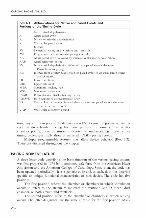
tion, P-synchronous pacing, the designation is PV. Because the pacemaker timingcycle in dual-chamber pacing has more portions to consider than single-chamber pacing, more discussion is devoted to understanding dual-chambertiming cycles, specifically those of universal (DDD) pacing systems.
Multiple programmable features may affect device behavior (Box 6.2).These are discussed throughout the chapter.
PACING NOMENCLATUREA three-letter code describing the basic function of the various pacing systemswas first proposed in 1974 by a combined task force from the American HeartAssociation and the American College of Cardiology. Since then, the code hasbeen updated periodically.1 It is a generic code and, as such, does not describespecific or unique functional characteristics of each device. The code has fivepositions.
The first position reflects the chamber or chambers in which stimulationoccurs. A refers to the atrium, V indicates the ventricle, and D means dualchamber, or both atrium and ventricle.
The second position refers to the chamber or chambers in which sensingoccurs. The letter designators are the same as those for the first position. Man-
CARDIAC PACING AND ICDS
266
Box 6.1. Abbreviations for Native and Paced Events and Portions of the Timing Cycle
P Native atrial depolarizationA Atrial paced eventR Native ventricular depolarizationV Ventricular paced eventI IntervalAV Sequential pacing in the atrium and ventricleAVI Programmed atrioventricular pacing intervalAR Atrial paced event followed by intrinsic ventricular depolarizationARP Atrial refractory periodPV Native atrial depolarization followed by a paced ventricular event,
P-synchronous pacingAEI Interval from a ventricular sensed or paced event to an atrial paced event,
the VA intervalLRL Lower rate limitURL Upper rate limitMTR Maximum tracking rateMSR Maximum sensor ratePVARP Postventricular atrial refractory periodRRAVD Rate-responsive atrioventricular delayVA Ventriculoatrial interval: interval from a sensed or paced ventricular event
to an atrial paced eventVRP Ventricular refractory period
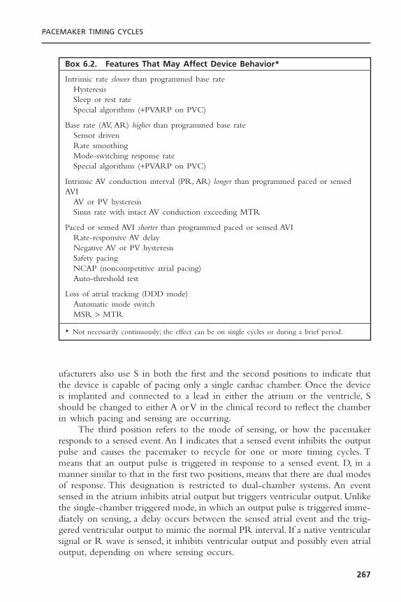
ufacturers also use S in both the first and the second positions to indicate thatthe device is capable of pacing only a single cardiac chamber. Once the deviceis implanted and connected to a lead in either the atrium or the ventricle, Sshould be changed to either A or V in the clinical record to reflect the chamberin which pacing and sensing are occurring.
The third position refers to the mode of sensing, or how the pacemakerresponds to a sensed event.An I indicates that a sensed event inhibits the outputpulse and causes the pacemaker to recycle for one or more timing cycles. Tmeans that an output pulse is triggered in response to a sensed event. D, in amanner similar to that in the first two positions, means that there are dual modesof response. This designation is restricted to dual-chamber systems. An eventsensed in the atrium inhibits atrial output but triggers ventricular output. Unlikethe single-chamber triggered mode, in which an output pulse is triggered imme-diately on sensing, a delay occurs between the sensed atrial event and the trig-gered ventricular output to mimic the normal PR interval. If a native ventricularsignal or R wave is sensed, it inhibits ventricular output and possibly even atrialoutput, depending on where sensing occurs.
PACEMAKER TIMING CYCLES
267
Box 6.2. Features That May Affect Device Behavior*
Intrinsic rate slower than programmed base rateHysteresisSleep or rest rateSpecial algorithms (+PVARP on PVC)
Base rate (AV, AR) higher than programmed base rateSensor drivenRate smoothingMode-switching response rateSpecial algorithms (+PVARP on PVC)
Intrinsic AV conduction interval (PR, AR) longer than programmed paced or sensedAVI
AV or PV hysteresisSinus rate with intact AV conduction exceeding MTR
Paced or sensed AVI shorter than programmed paced or sensed AVIRate-responsive AV delayNegative AV or PV hysteresisSafety pacingNCAP (noncompetitive atrial pacing)Auto-threshold test
Loss of atrial tracking (DDD mode)Automatic mode switchMSR > MTR
* Not necessarily continuously; the effect can be on single cycles or during a brief period.
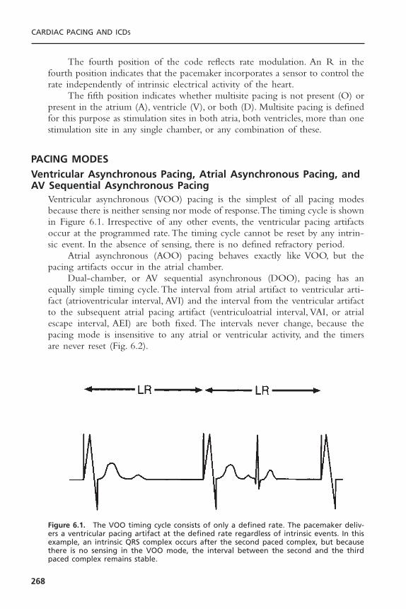
The fourth position of the code reflects rate modulation. An R in thefourth position indicates that the pacemaker incorporates a sensor to control therate independently of intrinsic electrical activity of the heart.
The fifth position indicates whether multisite pacing is not present (O) orpresent in the atrium (A), ventricle (V), or both (D). Multisite pacing is definedfor this purpose as stimulation sites in both atria, both ventricles, more than onestimulation site in any single chamber, or any combination of these.
PACING MODESVentricular Asynchronous Pacing, Atrial Asynchronous Pacing, andAV Sequential Asynchronous Pacing
Ventricular asynchronous (VOO) pacing is the simplest of all pacing modesbecause there is neither sensing nor mode of response.The timing cycle is shownin Figure 6.1. Irrespective of any other events, the ventricular pacing artifactsoccur at the programmed rate. The timing cycle cannot be reset by any intrin-sic event. In the absence of sensing, there is no defined refractory period.
Atrial asynchronous (AOO) pacing behaves exactly like VOO, but thepacing artifacts occur in the atrial chamber.
Dual-chamber, or AV sequential asynchronous (DOO), pacing has anequally simple timing cycle. The interval from atrial artifact to ventricular arti-fact (atrioventricular interval, AVI) and the interval from the ventricular artifactto the subsequent atrial pacing artifact (ventriculoatrial interval, VAI, or atrialescape interval, AEI) are both fixed. The intervals never change, because thepacing mode is insensitive to any atrial or ventricular activity, and the timersare never reset (Fig. 6.2).
CARDIAC PACING AND ICDS
268
Figure 6.1. The VOO timing cycle consists of only a defined rate. The pacemaker deliv-ers a ventricular pacing artifact at the defined rate regardless of intrinsic events. In thisexample, an intrinsic QRS complex occurs after the second paced complex, but becausethere is no sensing in the VOO mode, the interval between the second and the thirdpaced complex remains stable.
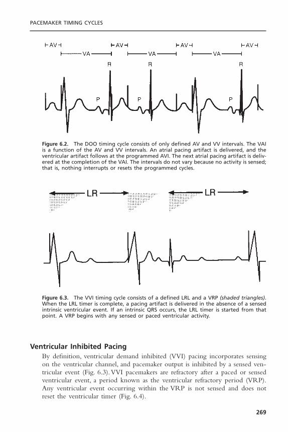
Ventricular Inhibited PacingBy definition, ventricular demand inhibited (VVI) pacing incorporates sensingon the ventricular channel, and pacemaker output is inhibited by a sensed ven-tricular event (Fig. 6.3).VVI pacemakers are refractory after a paced or sensedventricular event, a period known as the ventricular refractory period (VRP).Any ventricular event occurring within the VRP is not sensed and does notreset the ventricular timer (Fig. 6.4).
PACEMAKER TIMING CYCLES
269
Figure 6.2. The DOO timing cycle consists of only defined AV and VV intervals. The VAIis a function of the AV and VV intervals. An atrial pacing artifact is delivered, and theventricular artifact follows at the programmed AVI. The next atrial pacing artifact is deliv-ered at the completion of the VAI. The intervals do not vary because no activity is sensed;that is, nothing interrupts or resets the programmed cycles.
Figure 6.3. The VVI timing cycle consists of a defined LRL and a VRP (shaded triangles).When the LRL timer is complete, a pacing artifact is delivered in the absence of a sensedintrinsic ventricular event. If an intrinsic QRS occurs, the LRL timer is started from thatpoint. A VRP begins with any sensed or paced ventricular activity.

Atrial Inhibited PacingAtrial inhibited (AAI) pacing, the atrial counterpart of VVI pacing, incorporatesthe same timing cycles, with the obvious differences that pacing and sensingoccur from the atrium and pacemaker output is inhibited by a sensed atrialevent (Fig. 6.5). An atrial paced or sensed event initiates a refractory periodduring which the pacemaker senses nothing. Confusion can arise when multi-ple ventricular events occur during atrial pacing. For example, a premature ven-tricular beat following the intrinsic QRS that occurs in response to the pacedatrial beat does not inhibit an atrial pacing artifact from being delivered (Fig.6.6). When the AA timing cycle ends, the atrial pacing artifact is deliveredregardless of ventricular events, because an AAI pacemaker should not sense any-thing in the ventricle. The single exception to this rule is far-field sensing; thatis, the ventricular signal is large enough to be inappropriately sensed by the
CARDIAC PACING AND ICDS
270
Figure 6.4. If, in the VVI mode, a ventricular event occurs during the VRP (shaded tri-angles), it is not sensed and therefore does not reset the LRL timer.
Figure 6.5. The AAI timing cycle consists of a defined LRL and an ARP. When the LRLtimer is complete, a pacing artifact is delivered in the atrium in the absence of a sensedatrial event. If an intrinsic P wave occurs, the LRL timer is started from that point. AnARP begins with any sensed or paced atrial activity.

atrial lead (Fig. 6.7). In this situation, the atrial timing cycle is reset. Sometimesthis anomaly can be corrected either by making the atrial channel less sensitiveor by lengthening the refractory period.
Single-Chamber Triggered-Mode PacingIn single-chamber triggered-mode pacing, the pacemaker releases an outputpulse every time a native event is sensed.This feature increases the current drainon the battery, accelerating its rate of depletion. This mode of pacing alsodeforms the native signal, compromising ECG interpretation. However, it canserve as an excellent marker for the site of sensing within a complex. It canalso prevent inappropriate inhibition from oversensing when the patient doesnot have a stable native escape rhythm. In addition, it can be used for nonin-vasive electrophysiologic studies, with the already implanted pacemaker trackingchest wall stimuli created by a programmable stimulator. One special require-ment to use the triggered mode for noninvasive electrophysiologic studies isshortening the refractory period intentionally, thereby allowing the implanted
PACEMAKER TIMING CYCLES
271
Figure 6.6. In the AAI mode, only atrial activity is sensed. In this example, it may appearunusual for paced atrial activity to occur so soon after intrinsic ventricular activity.Because sensing occurs only in the atrium, ventricular activity would not be expected toreset the pacemaker’s timing cycle.
Figure 6.7. In this example of AAI pacing, the AA interval is 1000 milliseconds (60ppm).The interval between the second and third paced atrial events is greater than 1000 mil-liseconds. The interval from the second QRS complex to the subsequent atrial pacing arti-fact is 1000 milliseconds. This occurs because the second QRS complex (asterisk) has beensensed on the atrial lead (far-field sensing) and has inappropriately reset the timing cycle.LR = lower rate.
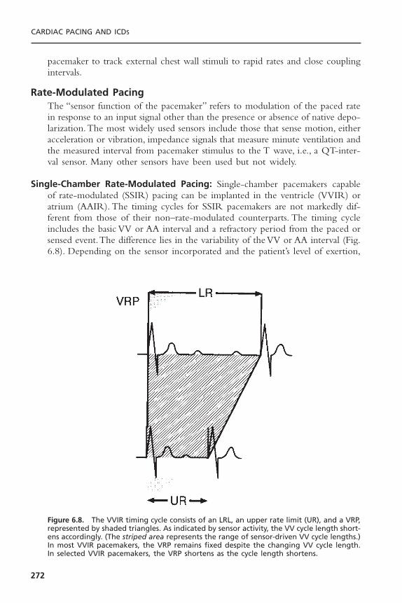
pacemaker to track external chest wall stimuli to rapid rates and close couplingintervals.
Rate-Modulated PacingThe “sensor function of the pacemaker” refers to modulation of the paced ratein response to an input signal other than the presence or absence of native depo-larization.The most widely used sensors include those that sense motion, eitheracceleration or vibration, impedance signals that measure minute ventilation andthe measured interval from pacemaker stimulus to the T wave, i.e., a QT-inter-val sensor. Many other sensors have been used but not widely.
Single-Chamber Rate-Modulated Pacing: Single-chamber pacemakers capableof rate-modulated (SSIR) pacing can be implanted in the ventricle (VVIR) oratrium (AAIR). The timing cycles for SSIR pacemakers are not markedly dif-ferent from those of their non–rate-modulated counterparts. The timing cycleincludes the basic VV or AA interval and a refractory period from the paced orsensed event.The difference lies in the variability of the VV or AA interval (Fig.6.8). Depending on the sensor incorporated and the patient’s level of exertion,
CARDIAC PACING AND ICDS
272
Figure 6.8. The VVIR timing cycle consists of an LRL, an upper rate limit (UR), and a VRP,represented by shaded triangles. As indicated by sensor activity, the VV cycle length short-ens accordingly. (The striped area represents the range of sensor-driven VV cycle lengths.)In most VVIR pacemakers, the VRP remains fixed despite the changing VV cycle length.In selected VVIR pacemakers, the VRP shortens as the cycle length shortens.
the basic interval is shorter than the programmed lower rate limit (LRL). Short-ening requires that an upper rate limit (URL) be programmed to define theabsolute shortest cycle length allowable. Most approved SSIR pacemakers incor-porate a fixed refractory period; that is, regardless of whether the pacemaker isoperating at the LRL or URL, the refractory period remains the same. Thus,at the higher rates under sensor drive, the pacemaker may effectively becomeSOOR, because the alert period during which sensing can occur is so abbre-viated. Native beats falling during the refractory period are not sensed. Hence,in SSIR pacing systems, if the refractory period is programmable, it should beprogrammed to a short interval to maximize the sensing period at both the lowand the high sensor-controlled rates. In some pacemakers, when the cycle lengthshortens, the refractory period shortens correspondingly; this is referred to asthe rate-variable refractory period. This event is analogous to the QT interval ofthe native ventricular depolarization.
Single-Chamber and Dual-Chamber Rate-Modulated Asynchronous Pacing:The asynchronous pacing modes (that is, AOO, VOO, and DOO, as explainedpreviously) have fixed intervals that are insensitive to all intrinsic events and havetimers that are never reset. If rate modulation is incorporated in an asynchro-nous pacing mode, the basic cycle length is altered by sensor activity. In thesingle-chamber rate-modulated asynchronous (AOOR and VOOR) pacingmodes, any alteration in cycle length is attributable to sensor activity and notto the sensing of intrinsic cardiac depolarizations. In the dual-chamber rate-modulated asynchronous (DOOR) pacing mode, the pacing rate changes inresponse to the sensor input signal but not to the native P or R wave. In somepacemakers, the AVI may be programmed to shorten progressively as the rateincreases, whereas in other units, it remains fixed at the initial programmedsetting.
Atrioventricular Sequential, Ventricular Inhibited PacingAV sequential, ventricular inhibited (DVI) pacing is rarely used. However, thispacing mode is a programmable option in most available dual-chamber pace-makers. For this reason, it is important to understand the timing cycles for DVIpacing.2,3
By definition, DVI provides pacing in both the atrium and the ventricle(D) but sensing only in the ventricle (V). The pacemaker is inhibited and resetby sensed ventricular activity but ignores all intrinsic atrial complexes.The DVIunits in the first generation were large and bulky and had two relatively largebipolar leads. The bipolar design produced small output pulses and generated a highly localized sensing field. In this setting, the ventricular sense amplifierremained alert when the atrial stimulus was released and throughout the AVI. Thus, a native R wave during the AVI was sensed so that ventricular output was inhibited and the AEI was reset (Fig. 6.9A). For both atrial and ventricular stimuli to be inhibited, the sensed R wave must occur during theAEI.
PACEMAKER TIMING CYCLES
273

Improvements in circuit design enabled the manufacturers to reduce thesize of the pulse generator.They also made the next generation unipolar to facil-itate venous access for the two leads. The large unipolar atrial stimulus couldbe sensed on the ventricular channel. It would be sensed by the pacemaker asa ventricular event and inhibit ventricular output. This occurrence is known ascrosstalk, which is potentially catastrophic if concomitant AV block is present.Toprevent crosstalk, the second generation of DVI pacemakers initiated the VRP
CARDIAC PACING AND ICDS
274
Figure 6.9. A: In the noncommitted version of DVI, the components of the timing cycleare the same as those for DVIC (see Fig. 6.10). However, if ventricular activity is sensedafter the atrial pacing artifact, ventricular output is inhibited; that is, a ventricular pacingartifact is not committed to the previous atrial pacing artifact. B: In the modified or par-tially committed version of DVI, ventricular events sensed within the nonphysiologic AVIdo not inhibit ventricular output, and a ventricular pacing stimulus occurs at the end ofthe interval. Ventricular events occurring within the physiologic AVI inhibit pacemakerfunction. In this example, the first paced atrial and ventricular events represent normalDVI pacing. The second paced atrial and intrinsic ventricular complex demonstrates aspontaneous ventricular event occurring within the nonphysiologic AVI and resulting ina ventricular pacing stimulus. In the third event shown, after an atrial paced event, aspontaneous ventricular event falls within the physiologic AVI, resulting in inhibition ofventricular pacing function.
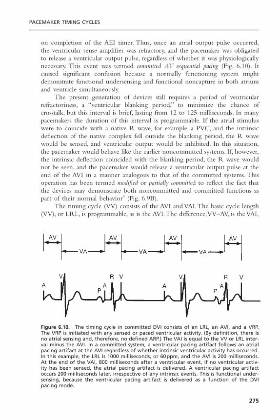
on completion of the AEI timer. Thus, once an atrial output pulse occurred,the ventricular sense amplifier was refractory, and the pacemaker was obligatedto release a ventricular output pulse, regardless of whether it was physiologicallynecessary. This event was termed committed AV sequential pacing (Fig. 6.10). Itcaused significant confusion because a normally functioning system mightdemonstrate functional undersensing and functional noncapture in both atriumand ventricle simultaneously.
The present generation of devices still requires a period of ventricularrefractoriness, a “ventricular blanking period,” to minimize the chance ofcrosstalk, but this interval is brief, lasting from 12 to 125 milliseconds. In manypacemakers the duration of this interval is programmable. If the atrial stimuluswere to coincide with a native R wave, for example, a PVC, and the intrinsicdeflection of the native complex fell outside the blanking period, the R wavewould be sensed, and ventricular output would be inhibited. In this situation,the pacemaker would behave like the earlier noncommitted systems. If, however,the intrinsic deflection coincided with the blanking period, the R wave wouldnot be seen, and the pacemaker would release a ventricular output pulse at theend of the AVI in a manner analogous to that of the committed systems. Thisoperation has been termed modified or partially committed to reflect the fact thatthe devices may demonstrate both noncommitted and committed functions aspart of their normal behavior4 (Fig. 6.9B).
The timing cycle (VV) consists of the AVI and VAI.The basic cycle length(VV), or LRL, is programmable, as is the AVI.The difference,VV–AV, is the VAI,
PACEMAKER TIMING CYCLES
275
Figure 6.10. The timing cycle in committed DVI consists of an LRL, an AVI, and a VRP.The VRP is initiated with any sensed or paced ventricular activity. (By definition, there isno atrial sensing and, therefore, no defined ARP.) The VAI is equal to the VV or LRL inter-val minus the AVI. In a committed system, a ventricular pacing artifact follows an atrialpacing artifact at the AVI regardless of whether intrinsic ventricular activity has occurred.In this example, the LRL is 1000 milliseconds, or 60ppm, and the AVI is 200 milliseconds.At the end of the VAI, 800 milliseconds after a ventricular event, if no ventricular activ-ity has been sensed, the atrial pacing artifact is delivered. A ventricular pacing artifactoccurs 200 milliseconds later, irrespective of any intrinsic events. This is functional under-sensing, because the ventricular pacing artifact is delivered as a function of the DVIpacing mode.
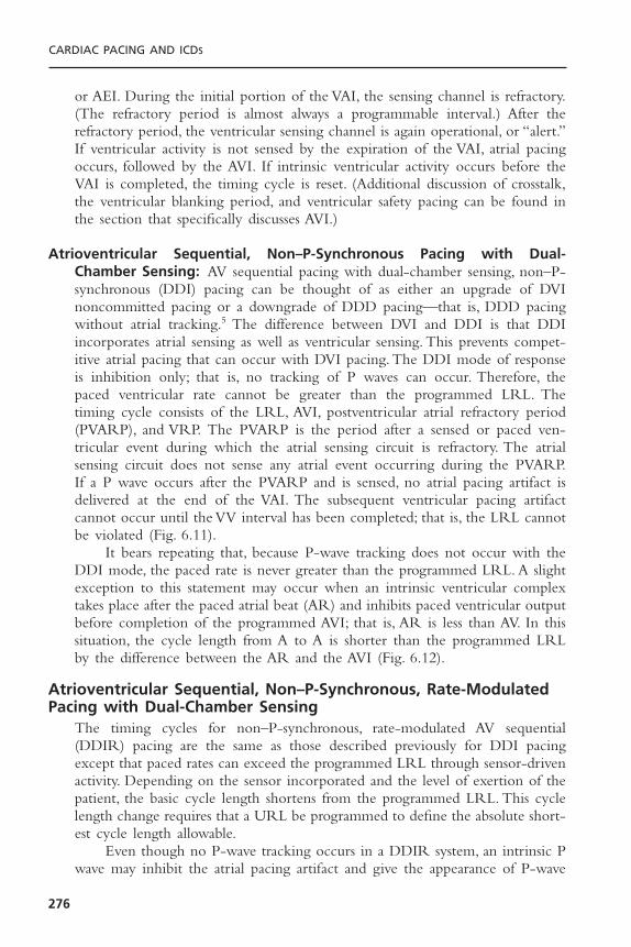
or AEI. During the initial portion of the VAI, the sensing channel is refractory.(The refractory period is almost always a programmable interval.) After therefractory period, the ventricular sensing channel is again operational, or “alert.”If ventricular activity is not sensed by the expiration of the VAI, atrial pacingoccurs, followed by the AVI. If intrinsic ventricular activity occurs before theVAI is completed, the timing cycle is reset. (Additional discussion of crosstalk,the ventricular blanking period, and ventricular safety pacing can be found inthe section that specifically discusses AVI.)
Atrioventricular Sequential, Non–P-Synchronous Pacing with Dual-Chamber Sensing: AV sequential pacing with dual-chamber sensing, non–P-synchronous (DDI) pacing can be thought of as either an upgrade of DVInoncommitted pacing or a downgrade of DDD pacing—that is, DDD pacingwithout atrial tracking.5 The difference between DVI and DDI is that DDIincorporates atrial sensing as well as ventricular sensing. This prevents compet-itive atrial pacing that can occur with DVI pacing.The DDI mode of responseis inhibition only; that is, no tracking of P waves can occur. Therefore, the paced ventricular rate cannot be greater than the programmed LRL. The timing cycle consists of the LRL, AVI, postventricular atrial refractory period(PVARP), and VRP. The PVARP is the period after a sensed or paced ven-tricular event during which the atrial sensing circuit is refractory. The atrialsensing circuit does not sense any atrial event occurring during the PVARP.If a P wave occurs after the PVARP and is sensed, no atrial pacing artifact isdelivered at the end of the VAI. The subsequent ventricular pacing artifact cannot occur until the VV interval has been completed; that is, the LRL cannotbe violated (Fig. 6.11).
It bears repeating that, because P-wave tracking does not occur with theDDI mode, the paced rate is never greater than the programmed LRL. A slightexception to this statement may occur when an intrinsic ventricular complextakes place after the paced atrial beat (AR) and inhibits paced ventricular outputbefore completion of the programmed AVI; that is, AR is less than AV. In thissituation, the cycle length from A to A is shorter than the programmed LRLby the difference between the AR and the AVI (Fig. 6.12).
Atrioventricular Sequential, Non–P-Synchronous, Rate-ModulatedPacing with Dual-Chamber Sensing
The timing cycles for non–P-synchronous, rate-modulated AV sequential(DDIR) pacing are the same as those described previously for DDI pacingexcept that paced rates can exceed the programmed LRL through sensor-drivenactivity. Depending on the sensor incorporated and the level of exertion of thepatient, the basic cycle length shortens from the programmed LRL. This cyclelength change requires that a URL be programmed to define the absolute short-est cycle length allowable.
Even though no P-wave tracking occurs in a DDIR system, an intrinsic Pwave may inhibit the atrial pacing artifact and give the appearance of P-wave
CARDIAC PACING AND ICDS
276
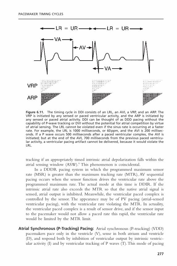
tracking if an appropriately timed intrinsic atrial depolarization falls within theatrial sensing window (ASW).6 This phenomenon is coincidental.
In a DDDR pacing system in which the programmed maximum sensorrate (MSR) is greater than the maximum tracking rate (MTR), AV sequentialpacing occurs when the sensor function drives the ventricular rate above theprogrammed maximum rate. The actual mode at this time is DDIR. If theintrinsic atrial rate also exceeds the MTR so that the native atrial signal issensed, atrial output is inhibited. Meanwhile, the ventricular paced complex iscontrolled by the sensor. The appearance may be of PV pacing (atrial-sensedventricular pacing), with the ventricular rate violating the MTR. In actuality,the ventricular paced complex is a result of sensor drive, and if the sensor inputto the pacemaker would not allow a paced rate this rapid, the ventricular ratewould be limited by the MTR limit.
Atrial Synchronous (P-Tracking) Pacing: Atrial synchronous (P-tracking) (VDD)pacemakers pace only in the ventricle (V), sense in both atrium and ventricle(D), and respond both by inhibition of ventricular output by intrinsic ventric-ular activity (I) and by ventricular tracking of P waves (T).This mode of pacing
PACEMAKER TIMING CYCLES
277
Figure 6.11. The timing cycle in DDI consists of an LRL, an AVI, a VRP, and an ARP. TheVRP is initiated by any sensed or paced ventricular activity, and the ARP is initiated byany sensed or paced atrial activity. DDI can be thought of as DDD pacing without thecapability of P-wave tracking or DVI without the potential for atrial competition by virtueof atrial sensing. The LRL cannot be violated even if the sinus rate is occurring at a fasterrate. For example, the LRL is 1000 milliseconds, or 60ppm, and the AVI is 200 millisec-onds. If a P wave occurs 500 milliseconds after a paced ventricular complex, the AVI isinitiated; but at the end of the AVI, 700 milliseconds from the previous paced ventricu-lar activity, a ventricular pacing artifact cannot be delivered, because it would violate theLRL.
is a programmable option in many dual-chamber pacemakers.7 The VDD modeis also available as a single-lead pacing system. In this system, a single lead iscapable of pacing in the ventricle in response to sensing atrial activity by wayof a remote electrode(s) situated on the intra-atrial portion of the ventricularpacing lead.
The timing cycle is composed of LRL, AVI, PVARP, VRP, and URL. Asensed atrial event initiates the AVI. If an intrinsic ventricular event occurs beforetermination of the AVI, ventricular output is inhibited, and the LRL timingcycle is reset. If a paced ventricular beat occurs at the end of the AVI, this beatresets the LRL. If no atrial event occurs, the pacemaker escapes with a pacedventricular event at the LRL; that is, the pacemaker displays VVI activity in theabsence of a sensed atrial event (Fig. 6.13).
Dual-Chamber Pacing and Sensing with Inhibition and TrackingAlthough the DDD timing cycle involves more intervals, standard dual-chamberpacing and sensing with inhibition and tracking (DDD) are reasonably easy tocomprehend on the basis of the timing cycles already discussed.7–12 The basic
CARDIAC PACING AND ICDS
278
Figure 6.12. Top: With ventricular-based timing in patients with intact AV nodal con-duction after AR pacing, the sensed R wave resets the AEI. The base pacing interval con-sists of the sum of the AR and the AEI; thus, it is shorter than the programmed minimumrate interval. Bottom: With atrial-based timing in patients with intact AV nodal con-duction after AR pacing, the sensed R wave inhibits ventricular output but does not reset the basic timing of the pacemaker. There is atrial pacing at the programmed baserate. (From Levine PA, Hayes DL, Wilkoff BL, Ohman AE. Electrocardiography of rate-modulated pacemaker rhythms. Sylmar, CA: Siemens-Pacesetter, 1990. By permission ofSiemens-Pacesetter.)
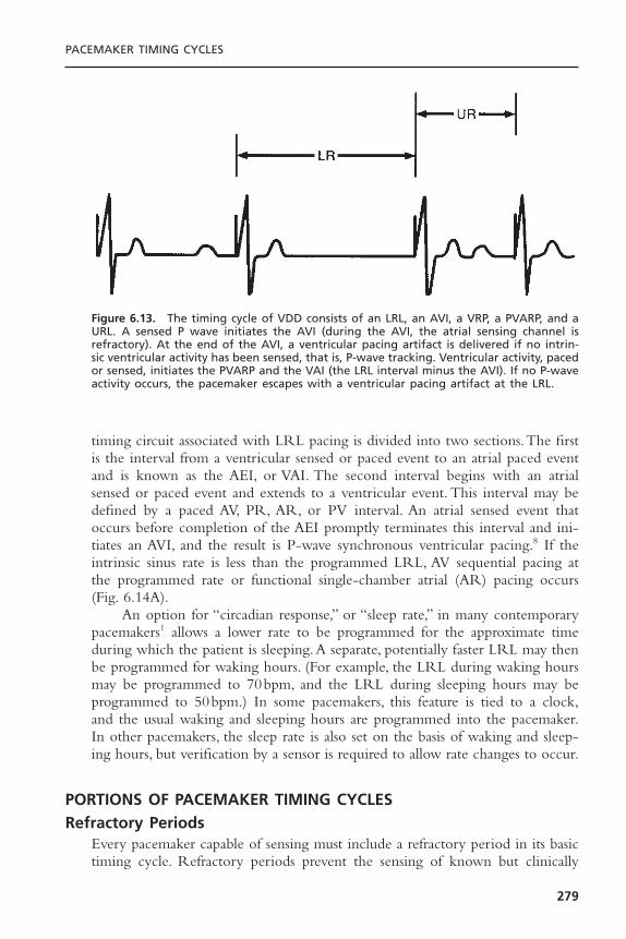
timing circuit associated with LRL pacing is divided into two sections.The firstis the interval from a ventricular sensed or paced event to an atrial paced eventand is known as the AEI, or VAI. The second interval begins with an atrialsensed or paced event and extends to a ventricular event. This interval may bedefined by a paced AV, PR, AR, or PV interval. An atrial sensed event thatoccurs before completion of the AEI promptly terminates this interval and ini-tiates an AVI, and the result is P-wave synchronous ventricular pacing.8 If theintrinsic sinus rate is less than the programmed LRL, AV sequential pacing atthe programmed rate or functional single-chamber atrial (AR) pacing occurs(Fig. 6.14A).
An option for “circadian response,” or “sleep rate,” in many contemporarypacemakers1 allows a lower rate to be programmed for the approximate timeduring which the patient is sleeping.A separate, potentially faster LRL may thenbe programmed for waking hours. (For example, the LRL during waking hoursmay be programmed to 70bpm, and the LRL during sleeping hours may beprogrammed to 50bpm.) In some pacemakers, this feature is tied to a clock,and the usual waking and sleeping hours are programmed into the pacemaker.In other pacemakers, the sleep rate is also set on the basis of waking and sleep-ing hours, but verification by a sensor is required to allow rate changes to occur.
PORTIONS OF PACEMAKER TIMING CYCLESRefractory Periods
Every pacemaker capable of sensing must include a refractory period in its basictiming cycle. Refractory periods prevent the sensing of known but clinically
PACEMAKER TIMING CYCLES
279
Figure 6.13. The timing cycle of VDD consists of an LRL, an AVI, a VRP, a PVARP, and aURL. A sensed P wave initiates the AVI (during the AVI, the atrial sensing channel isrefractory). At the end of the AVI, a ventricular pacing artifact is delivered if no intrin-sic ventricular activity has been sensed, that is, P-wave tracking. Ventricular activity, pacedor sensed, initiates the PVARP and the VAI (the LRL interval minus the AVI). If no P-waveactivity occurs, the pacemaker escapes with a ventricular pacing artifact at the LRL.

CARDIAC PACING AND ICDS
280
A
B
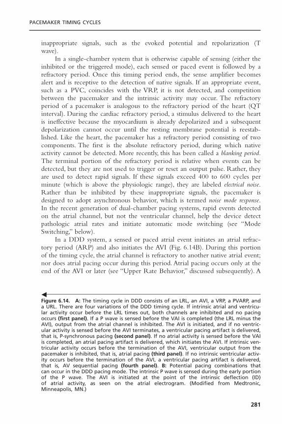
inappropriate signals, such as the evoked potential and repolarization (T wave).
In a single-chamber system that is otherwise capable of sensing (either theinhibited or the triggered mode), each sensed or paced event is followed by arefractory period. Once this timing period ends, the sense amplifier becomesalert and is receptive to the detection of native signals. If an appropriate event,such as a PVC, coincides with the VRP, it is not detected, and competitionbetween the pacemaker and the intrinsic activity may occur. The refractoryperiod of a pacemaker is analogous to the refractory period of the heart (QTinterval). During the cardiac refractory period, a stimulus delivered to the heartis ineffective because the myocardium is already depolarized and a subsequentdepolarization cannot occur until the resting membrane potential is reestab-lished. Like the heart, the pacemaker has a refractory period consisting of twocomponents. The first is the absolute refractory period, during which nativeactivity cannot be detected. More recently, this has been called a blanking period.The terminal portion of the refractory period is relative when events can bedetected, but they are not used to trigger or reset an output pulse. Rather, theyare used to detect rapid signals. If these signals exceed 400 to 600 cycles perminute (which is above the physiologic range), they are labeled electrical noise.Rather than be inhibited by these inappropriate signals, the pacemaker isdesigned to adopt asynchronous behavior, which is termed noise mode response.In the recent generation of dual-chamber pacing systems, rapid events detectedon the atrial channel, but not the ventricular channel, help the device detectpathologic atrial rates and initiate automatic mode switching (see “ModeSwitching,” below).
In a DDD system, a sensed or paced atrial event initiates an atrial refrac-tory period (ARP) and also initiates the AVI (Fig. 6.14B). During this portionof the timing cycle, the atrial channel is refractory to another native atrial event;nor does atrial pacing occur during this period. Atrial pacing occurs only at theend of the AVI or later (see “Upper Rate Behavior,” discussed subsequently). A
PACEMAKER TIMING CYCLES
281
Figure 6.14. A: The timing cycle in DDD consists of an LRL, an AVI, a VRP, a PVARP, anda URL. There are four variations of the DDD timing cycle. If intrinsic atrial and ventricu-lar activity occur before the LRL times out, both channels are inhibited and no pacingoccurs (first panel). If a P wave is sensed before the VAI is completed (the LRL minus theAVI), output from the atrial channel is inhibited. The AVI is initiated, and if no ventric-ular activity is sensed before the AVI terminates, a ventricular pacing artifact is delivered,that is, P-synchronous pacing (second panel). If no atrial activity is sensed before the VAIis completed, an atrial pacing artifact is delivered, which initiates the AVI. If intrinsic ven-tricular activity occurs before the termination of the AVI, ventricular output from thepacemaker is inhibited, that is, atrial pacing (third panel). If no intrinsic ventricular activ-ity occurs before the termination of the AVI, a ventricular pacing artifact is delivered,that is, AV sequential pacing (fourth panel). B: Potential pacing combinations that can occur in the DDD pacing mode. The intrinsic P wave is sensed during the early portionof the P wave. The AVI is initiated at the point of the intrinsic deflection (ID) of atrial activity, as seen on the atrial electrogram. (Modified from Medtronic, Minneapolis, MN.)
�
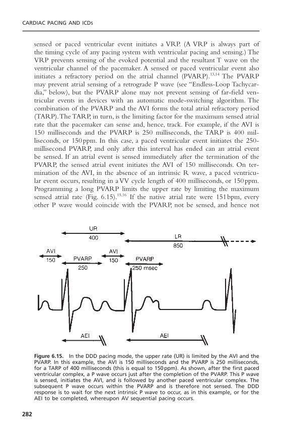
sensed or paced ventricular event initiates a VRP. (A VRP is always part of the timing cycle of any pacing system with ventricular pacing and sensing.) TheVRP prevents sensing of the evoked potential and the resultant T wave on theventricular channel of the pacemaker. A sensed or paced ventricular event alsoinitiates a refractory period on the atrial channel (PVARP).13,14 The PVARPmay prevent atrial sensing of a retrograde P wave (see “Endless-Loop Tachycar-dia,” below), but the PVARP alone may not prevent sensing of far-field ven-tricular events in devices with an automatic mode-switching algorithm. Thecombination of the PVARP and the AVI forms the total atrial refractory period(TARP).The TARP, in turn, is the limiting factor for the maximum sensed atrialrate that the pacemaker can sense and, hence, track. For example, if the AVI is150 milliseconds and the PVARP is 250 milliseconds, the TARP is 400 mil-liseconds, or 150ppm. In this case, a paced ventricular event initiates the 250-millisecond PVARP, and only after this interval has ended can an atrial eventbe sensed. If an atrial event is sensed immediately after the termination of thePVARP, the sensed atrial event initiates the AVI of 150 milliseconds. On ter-mination of the AVI, in the absence of an intrinsic R wave, a paced ventricu-lar event occurs, resulting in a VV cycle length of 400 milliseconds, or 150ppm.Programming a long PVARP limits the upper rate by limiting the maximumsensed atrial rate (Fig. 6.15).15,16 If the native atrial rate were 151bpm, everyother P wave would coincide with the PVARP, not be sensed, and hence not
CARDIAC PACING AND ICDS
282
Figure 6.15. In the DDD pacing mode, the upper rate (UR) is limited by the AVI and thePVARP. In this example, the AVI is 150 milliseconds and the PVARP is 250 milliseconds,for a TARP of 400 milliseconds (this is equal to 150ppm). As shown, after the first pacedventricular complex, a P wave occurs just after the completion of the PVARP. This P waveis sensed, initiates the AVI, and is followed by another paced ventricular complex. Thesubsequent P wave occurs within the PVARP and is therefore not sensed. The DDDresponse is to wait for the next intrinsic P wave to occur, as in this example, or for theAEI to be completed, whereupon AV sequential pacing occurs.

be tracked; so the effective paced rate would be approximately 75ppm, or halfthe atrial rate.
In a pacemaker with a mode-switching algorithm “on,” the pacemaker mustbe able to detect higher atrial rates, even if the native P waves coincide withthe PVARP. Although these P waves may not be tracked, the pacemaker iscapable of monitoring events that coincide with the refractory period to rec-ognize rapid pathologic atrial rates. Thus, the system can switch from a track-ing mode (DDD) to a nontracking mode (VVI or DDI), so that the first of thepathologic atrial events that occur during the atrial alert period is not tracked.
Atrioventricular IntervalThe AVI, often poorly understood, should be considered a single interval withtwo subportions (Fig. 6.16A).17 For most dual-chamber systems, the atrial
PACEMAKER TIMING CYCLES
283
A
Figure 6.16. A: The AVI should be considered as a single interval with two subportions.The entire AVI corresponds to the programmed value, that is, the interval following apaced or sensed atrial beat allowed before a ventricular pacing artifact is delivered. Theinitial portion of the AVI is the blanking period. This interval is followed by the crosstalksensing window. B: If the ventricular sensing circuit senses activity during the crosstalksensing window, a ventricular pacing artifact is delivered early, usually at 100 to 110 mil-liseconds after the atrial event. This has been referred to as “ventricular safety pacing,”“110-millisecond phenomenon,” and “nonphysiologic AV delay.” C: The initial portion ofthe AVI in most dual-chamber pacemakers is designated as the blanking period. Duringthis portion of the AVI, sensing is suspended. The primary purpose of this interval is toprevent ventricular sensing of the leading edge of the atrial pacing artifact. Any eventthat occurs during the blanking period, even if it is an intrinsic ventricular event (asshown in this figure), is not sensed. In this example, the ventricular premature beat thatis not sensed is followed by a ventricular pacing artifact delivered at the programmedAVI and occurring in the terminal portion of the T wave.

CARDIAC PACING AND ICDS
284
Figure 6.16. Continued
C
B

channel is totally refractory to the detection of other atrial signals that mayoccur during the AVI. In most devices, only the first portion of the AVI isabsolutely refractory.The terminal portion is a relative refractory period, to assistin the detection of rapid pathologic atrial rhythms for purposes of mode switch-ing (Fig. 6.17).
Atrial output also triggers a timing period on the ventricular channel,known as the ventricular blanking period. It coincides with the earliest portion ofthe AVI, and its purpose is to avoid sensing of an event or a stimulus of onechannel in the opposite channel.18–20
If the atrial pacing artifact were sensed by the ventricular sensing circuit,ventricular output inhibition would result, i.e., crosstalk.To prevent crosstalk, theleading edge of the atrial pacing artifact is masked, or blanked, by rendering theventricular sensing circuit absolutely refractory during the very early portion ofthe AVI (Fig. 6.16B). In DDD pacemakers, the blanking period may be pro-grammable, ranging from 12 to 125 milliseconds. The blanking period is tradi-tionally of short duration because it is important for the ventricular sensingcircuit to be returned to the “alert” state relatively early during the AVI so thatintrinsic ventricular activity can inhibit pacemaker output if it occurs before theAVI ends. The potential exists for signals other than those of intrinsic ventric-ular activity to be sensed and inhibit ventricular output. The greatest concernis crosstalk.19,21 Even though the leading edge of the atrial pacing artifact is effec-tively ignored because of the blanking period, the trailing edge of the atrialpacing artifact occurring after the blanking period can occasionally be sensedon the ventricular channel. In a pacemaker-dependent patient, inhibition of ven-tricular output by crosstalk results in asystole. To prevent such an outcome, asafety mechanism is present.
If activity is sensed on the ventricular sensing circuit in a given portion ofthe AVI immediately after the blanking period (this second portion of the AVI
PACEMAKER TIMING CYCLES
285
Figure 6.17. Surface ECG, atrial electrogram, and event markers (arrows) demonstratingoccasional AR complexes, events that are occurring within the ARP. They coincide withthe QRS complex but are detected on the atrial channel before being detected by thepacemaker on the ventricular channel.

has been called the “ventricular triggering period” or the “crosstalk sensingwindow”), it is assumed that crosstalk cannot be differentiated from intrinsicventricular activity. To prevent catastrophic ventricular asystole, a ventricularpacing artifact is delivered early—at an AVI of 100 to 120 milliseconds, althoughin some pulse generators this interval is programmable for 50 to 150 millisec-onds (Fig. 6.16C).22 If the signal sensed is indeed crosstalk, a paced ventricularcomplex delivered at the abbreviated interval prevents ventricular asystole. Inaddition, AV pacing at a shorter-than-programmed AVI on the ECG indicatesthe occurrence of crosstalk and allows the pacemaker to be programmed toeliminate this behavior. Elimination of crosstalk may be accomplished by extend-ing the ventricular blanking period, decreasing atrial output, or reducing theventricular sensitivity. Or, if true intrinsic ventricular activity occurs during theearly portion of the AVI, the safety mechanism results in delivery of a ventric-ular pacing artifact within or immediately after the intrinsic beat. This deliveryis safe because the ventricle is refractory, no depolarization results from thepacing artifact, and the pacing artifact is delivered too early to coincide withventricular repolarization or a vulnerable period. This event has been referredto as “ventricular safety pacing,” “nonphysiologic AV delay,” or the “110-mil-lisecond phenomenon.” Although the safety pacing phenomenon accompanyinga late-cycle PVC has been interpreted as a sensing failure, it actually reflectsnormal sensing. Pacemaker behavior changes with respect to a ventricular eventthat is sensed during the “crosstalk sensing” window. The response is altered incomparison with an event sensed at any other time during the ventricular alertperiod. Sensing during this special brief timing period results in a triggeredrather than an inhibited output. Unlike single-chamber function in which thetriggered mode rapidly delivers an output pulse as soon as an event is detected,the R wave that occurs in the earliest portion of this special detection intervaltriggers an output at the end of the safety pacing interval.
After the blanking period and the crosstalk sensing window have timedout, the ventricular sensing circuit returns to the alert status, in which a detectedevent causes the output pulse to be reset.
Differential Atrioventricular Interval: If AVIs initiated by a sensed event andthose initiated by a paced event show consistent differences, the most likelyexplanation is a differential AVI. As noted in the introduction to this section, adifferential AVI is an attempt to provide an interatrial conduction time of equalduration whether atrial contraction is paced or sensed. The PV interval initi-ated with atrial sensing commences only when the atrial depolarization isdetected by the pacemaker and commonly occurs 20 to 60 milliseconds afterthe onset of the P wave seen on a surface ECG. Conversely, the AVI initiatedwith atrial pacing commences immediately with the pacing artifact, not withatrial depolarization.The AVI that follows a sensed atrial event should thereforebe shorter than one that follows a paced atrial event (Fig. 6.18) in an effort toachieve similar functional AVIs, whether the atrial event is paced or sensed.TheAVI differential is programmable in some pacemakers and preset in others.
CARDIAC PACING AND ICDS
286
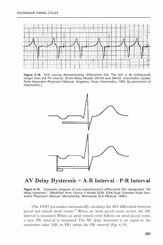
One DDD pacemaker automatically calculates the AVI differential betweenpaced and sensed atrial events.23 When an atrial paced event occurs, the ARinterval is measured. When an atrial sensed event follows an atrial paced event,a new PR interval is measured. The AV delay hysteresis is set equal to themaximum value (AR or PR) minus the PR interval (Fig. 6.19).
PACEMAKER TIMING CYCLES
287
Figure 6.18. ECG tracing demonstrating differential AVI. The AVI is 50 millisecondslonger than the PV interval. (From Relay Models 293-03 and 294-03. Intermedics CardiacPulse Generator Physician’s Manual. Angleton, Texas: Intermedics, 1992. By permission ofIntermedics.)
Figure 6.19. Schematic diagram of one manufacturer’s differential AVI, designated “AVdelay hysteresis.” (Modified from Chorus II Model 6234, 6244 Dual Chamber Pulse Gen-erator Physician’s Manual. Minnetonka, Minnesota: ELA Medical, 1994.)

Most dual-chamber pacemakers allow the paced and sensed AV delays tobe programmed independently. Although the two may be nominally different,wider differences up to 100 milliseconds are programmable.
Rate-Variable or Rate-Adaptive Atrioventricular Interval: Most DDD andDDDR pacemakers can shorten the AVI as the atrial rate increases, either byan increase in sinus rate or by a sensor-driven increase in paced rate (Fig. 6.20).Rate-adaptive or rate-variable AVI is intended to optimize cardiac output bymimicking the normal physiologic decrease in the PR interval that occurs inthe normal heart as the atrial rate increases.24–26 The rate-related shortening ofthe AVI may also improve atrial sensing by shortening the TARP and therebyextending the time for the ASW.
Rate-adaptive AVI may be designed in several ways. The more commonmethod is to allow linear shortening of the AVI from a programmed base-line AVI to a programmed minimum AVI. Another method allows a limitednumber of stepwise shortenings of the AVI. These steps may or may not be programmable.
Atrioventricular Interval Hysteresis: The term AVI hysteresis has been used var-iously but most commonly describes alterations in the paced AVI relative to thepatient’s intrinsic AV conduction. For example, a longer paced AVI is permit-ted, to allow maintenance of intrinsic AV conduction. However, once the intrin-sic PR or AR interval triggers the programmed AVI hysteresis, consistent AVpacing at the programmed AVI occurs. Commonly,AVI hysteresis is programmedby selecting the desired AV delay during pacing with an additional program-mable delta. If there is AV pacing, the system periodically extends the AV delayby the programmed delta. If a native R wave is detected within this extendedinterval, the longer interval remains in place and results in functional single-chamber atrial pacing. However, with the first cycle of AV pacing, which mayoccur with a transient increase in vagal tone or even intermittent pathologicAV block, the AV delay returns to the programmed value.
CARDIAC PACING AND ICDS
288
Figure 6.20. As heart rate increases, AV delay dynamically adapts to the change in cyclelength. (From Hayes DL, Ketelson A, Levine PA, et al. Understanding timing systems ofcurrent DDDR pacemakers. Eur JCPE 1993;3:70–86. By permission of Mayo Foundation.)

This programming accomplishes two goals. In a patient with a normal ven-tricle, normal ventricular activation sequence (narrow QRS), and a normal PRinterval, single-chamber atrial pacing provides hemodynamics superior to thoseof dual-chamber pacing. Ventricular stimulation causes a disordered ventricularactivation sequence. However, an AV delay that is too long, as in first-degreeAV block, may be hemodynamically deleterious. In this situation, hemodynam-ics may be superior with a shorter AV delay despite the disordered ventricularactivation sequence. AVI hysteresis allows for both a longer AV delay when AVnodal conduction is intact and a shorter AVI when conduction is compromised.
Hysteresis ProgrammingProgramming of hysteresis permits prolongation of the first pacemaker escapeinterval after a sensed event.A pacemaker programmed at a cycle length of 1000milliseconds (60bpm) and a hysteresis of 1200 milliseconds (50bpm) allows 200milliseconds more for another sensed QRS complex. If another QRS complexis not recognized, then the pacemaker continuously stimulates the heart at theprogrammed rate of 60bpm, an escape interval of 1000 milliseconds (Fig. 6.21),until a sensed event restarts the cycle. The advantage of hysteresis in a single-chamber pacing mode is the ability to maintain spontaneous AV synchrony aslong as possible.2 This feature may prevent symptomatic retrograde VA conduc-tion. In patients with VVI pacing and pacemaker syndrome, hysteresis providesreliable higher rate backup pacing while increasing the potential for maintain-ing the patient’s intrinsic rhythm.
Several types of hysteresis may be programmable options in some dual-chamber pacemakers. In the first-generation algorithm, a native event had to besensed to reestablish the hysteresis escape interval. The native complex had tooccur at a rate faster than the basic pacing rate. If the basic pacing rate was rel-atively high, the system may have continued pacing long after the need forpacing had resolved. Therefore, search hysteresis was introduced. In search hys-teresis, once a specific number of timing cycles at the more rapid rate (thenumber of cycles may be fixed or programmable) has occurred, the prolongedescape interval is permitted to allow manifestation of a slower intrinsic rate—that is, a rate higher than the programmed LRL. If intrinsic rhythm does notreturn at a rate exceeding the programmed lower rate, stimulation resumes atthe more rapid rate for a given number of cycles (Fig. 6.22). This feature hasbeen further modified in some systems to prevent an isolated PVC from reset-ting the basic dual-chamber pacing interval. Rather, resetting the hysteresisescape interval requires a sensed P wave to produce either a PR or a PVcomplex that inhibits the higher rate of pacing and reestablishes the hysteresisfeature.
Another feature can be considered a refinement of search hysteresis.3 A“sudden bradycardia response” or “rate drop response” (RDR) reacts to adefined drop in heart rate. When this occurs, the pacemaker feature intervenesby pacing at an elevated rate in both chambers for a specific, programmed dura-tion (Fig. 6.23). At the conclusion of the programmed duration of more rapid
PACEMAKER TIMING CYCLES
289
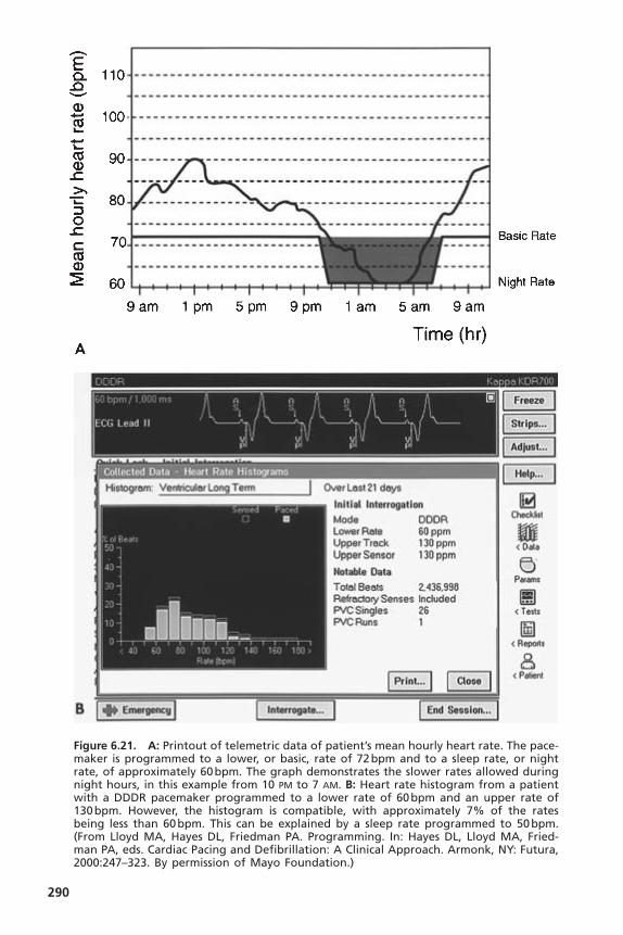
290
Figure 6.21. A: Printout of telemetric data of patient’s mean hourly heart rate. The pace-maker is programmed to a lower, or basic, rate of 72bpm and to a sleep rate, or nightrate, of approximately 60bpm. The graph demonstrates the slower rates allowed duringnight hours, in this example from 10 PM to 7 AM. B: Heart rate histogram from a patientwith a DDDR pacemaker programmed to a lower rate of 60bpm and an upper rate of130bpm. However, the histogram is compatible, with approximately 7% of the ratesbeing less than 60bpm. This can be explained by a sleep rate programmed to 50bpm.(From Lloyd MA, Hayes DL, Friedman PA. Programming. In: Hayes DL, Lloyd MA, Fried-man PA, eds. Cardiac Pacing and Defibrillation: A Clinical Approach. Armonk, NY: Futura,2000:247–323. By permission of Mayo Foundation.)
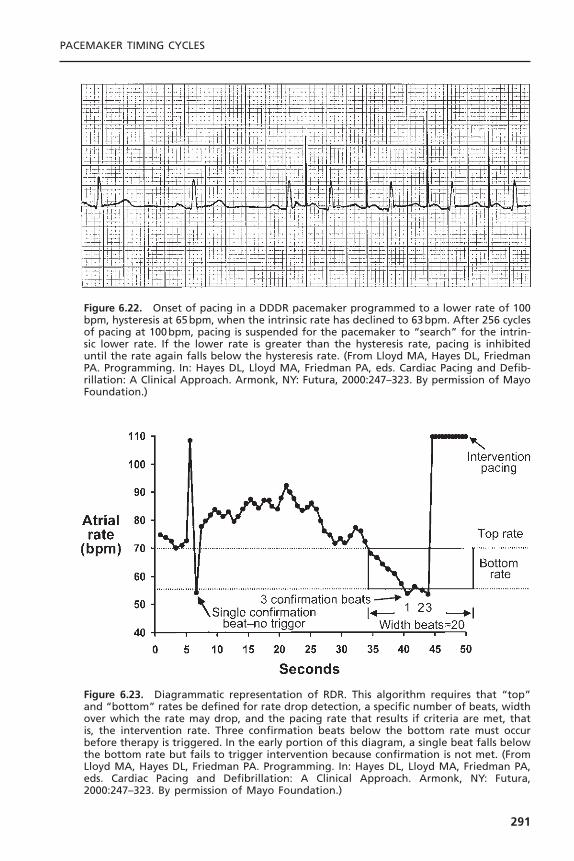
PACEMAKER TIMING CYCLES
291
Figure 6.22. Onset of pacing in a DDDR pacemaker programmed to a lower rate of 100bpm, hysteresis at 65bpm, when the intrinsic rate has declined to 63bpm. After 256 cyclesof pacing at 100bpm, pacing is suspended for the pacemaker to “search” for the intrin-sic lower rate. If the lower rate is greater than the hysteresis rate, pacing is inhibiteduntil the rate again falls below the hysteresis rate. (From Lloyd MA, Hayes DL, FriedmanPA. Programming. In: Hayes DL, Lloyd MA, Friedman PA, eds. Cardiac Pacing and Defib-rillation: A Clinical Approach. Armonk, NY: Futura, 2000:247–323. By permission of MayoFoundation.)
Figure 6.23. Diagrammatic representation of RDR. This algorithm requires that “top”and “bottom” rates be defined for rate drop detection, a specific number of beats, widthover which the rate may drop, and the pacing rate that results if criteria are met, thatis, the intervention rate. Three confirmation beats below the bottom rate must occurbefore therapy is triggered. In the early portion of this diagram, a single beat falls belowthe bottom rate but fails to trigger intervention because confirmation is not met. (FromLloyd MA, Hayes DL, Friedman PA. Programming. In: Hayes DL, Lloyd MA, Friedman PA,eds. Cardiac Pacing and Defibrillation: A Clinical Approach. Armonk, NY: Futura,2000:247–323. By permission of Mayo Foundation.)

pacing, the pacing rate gradually returns to the programmed lower rate. Severalprogrammable detection algorithms are available. The first algorithm availablewas “drop detect,” in which the pacemaker monitors a drop in heart rate thatmust satisfy two programmable requirements to trigger an intervention, namely,the programmable “drop size,” which is the number of beats the rate must fall,and the “detection window,” which is the amount of time monitored for a ratedrop (this is a programmable interval) (Fig. 6.24).The “nominal” values for RDRare not successful for everyone.
In the “low rate detect” algorithm, therapy is triggered when pacing occursat the programmed lower rate for the programmable consecutive number of“detection beats.” This detection method can be used as a backup to the “dropdetect” method if the sudden drop in rate varies between slow and fast (Fig.6.25).4
Dual-chamber rate hysteresis has multiple variations and different levels ofcomplexity. Although the primary mode of therapy for vasovagal syncope ispharmacologic, it is not always 100% successful. Another treatment objective isdual-chamber pacing support at a relatively high rate during each spell, whichmay be effective in ameliorating if not totally eliminating the episodes. Becausepatients with neurocardiogenic syncope have a normal rhythm at other times,the hysteresis circuit allows for pacing at the higher rate only during the spell (when the native heart rate falls precipitously) and otherwise remains inhibited.27,28
BASE RATE BEHAVIORThe way a pacemaker behaves in response to a sensed ventricular signal variesamong manufacturers and even among devices from the same manufacturer.Dual-chamber pacemakers have historically been designed with a ventricular-based timing system, an atrial-based timing system, or a hybrid of these twosystems.3,29 Designation of a pacemaker’s timing system as atrial-based or ven-tricular-based gained increased importance with the advent of rate-adaptivepacing.The difference between atrial-based and ventricular-based dual-chamberpacemakers was of little clinical importance in non–rate-adaptive pacemakers,although the difference created some minor confusion in interpretation of pacedECGs.
With the refinement of timing systems, use of a specific system has onceagain become less important. A description of pure atrial-based and ventricu-lar-based timing systems appears below. However, few contemporary dual-chamber pacemakers are “pure” atrial-based or ventricular-based systems. Themajority is in some way hybrid, designed specifically to avoid the potential ratevariations or limitations that could occur with either pure timing system.
Ventricular-Based TimingIn a ventricular-based timing system, the AEI is “fixed.” A ventricular sensedevent occurring during the AEI resets this timer, causing it to start again (Fig.
CARDIAC PACING AND ICDS
292

293
Figure 6.24. A: The RDR counters indicate that the pacemaker had documented mul-tiple episodes of sudden rate drop. However, “therapy”—that is, a response to thesudden drop in rate with an increase in pacing rate for a programmed period—had notbeen initiated. B: With a pacemaker in place and RDR that had been programmed “on”but not initiated because of the programmed parameters, adjusting the RDR parameterswould be reasonable. For this patient, the RDR criteria were programmed more sensi-tively. When the patient returned, the rate counter was again full, with 255 episodesdetected and therapy delivered on two occasions. The second printout details the eventon April 18 at 05:35 when therapy was delivered. The diagram documents a sud-den decrease in rate; RDR was met and therapy delivered. (From Lloyd MA, Hayes DL,Friedman PA. Programming. In: Hayes DL, Lloyd MA, Friedman PA, eds. Cardiac Pacingand Defibrillation: A Clinical Approach. Armonk, NY: Futura, 2000:247–323. By permissionof Mayo Foundation.)

6.26, top). A ventricular sensed event occurring during the AVI both terminatesthe AVI and initiates an AEI (see Fig. 6.12, top). If there is intact conductionthrough the AV node after an atrial pacing stimulus such that the AR interval(atrial stimulus to sensed R wave) is shorter than the programmed AVI, theresulting paced rate accelerates by a small amount.This response is demonstratedin Figure 6.12 (top).
This phenomenon is best understood by example. In a pacemaker pro-grammed to an LRL of 60bpm (a pacing interval of 1000 milliseconds) thathas a programmed AVI of 200 milliseconds, the AEI is 800 milliseconds (AEI= LRL - AVI). If AV nodal function permits conduction in 150 milliseconds(AR interval + 150 milliseconds), the conducted or sensed R wave inhibits ven-tricular output. This, in turn, resets the AEI, which remains stable at 800 mil-liseconds.The resulting interval between consecutive atrial pacing stimuli is 950milliseconds (AEI + AR interval), which is equivalent to a rate of 63bpm, a rateslightly faster than the programmed LRL. When a native R wave occurs—forexample, a ventricular premature beat during the AEI—the AEI is also reset.The pacemaker then recycles, resulting in a rate defined by the sum of the AEIand AVI. This escape interval is therefore equal to the LRL (Fig. 6.26, top). Inboth cases, the sensed ventricular event, an R wave, regardless of where it occurs,resets the AEI.
CARDIAC PACING AND ICDS
294
Figure 6.25. In the low rate detect algorithm (Medtronic, Inc.), when pacing occurs atthe programmed lower rate for the programmable consecutive number of detectionbeats, therapy is triggered. Low rate detect may be used as a backup to the drop detectmethod if the sudden drop in rate varies between slow and fast. (From Lloyd MA, HayesDL, Friedman PA. Programming. In: Hayes DL, Lloyd MA, Friedman PA, eds. Cardiac Pacingand Defibrillation: A Clinical Approach. Armonk, NY: Futura, 2000:247–323. By permissionof Mayo Foundation.)
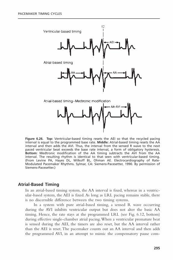
Atrial-Based TimingIn an atrial-based timing system, the AA interval is fixed, whereas in a ventric-ular-based system, the AEI is fixed. As long as LRL pacing remains stable, thereis no discernible difference between the two timing systems.
In a system with pure atrial-based timing, a sensed R wave occurringduring the AVI inhibits ventricular output but does not alter the basic AAtiming. Hence, the rate stays at the programmed LRL (see Fig. 6.12, bottom)during effective single-chamber atrial pacing.When a ventricular premature beatis sensed during the AEI, the timers are also reset, but the AA interval ratherthan the AEI is reset. The pacemaker counts out an AA interval and then addsthe programmed AVI, in an attempt to mimic the compensatory pause com-
PACEMAKER TIMING CYCLES
295
Figure 6.26. Top: Ventricular-based timing resets the AEI so that the recycled pacinginterval is equal to the programmed base rate. Middle: Atrial-based timing resets the AAinterval and then adds the AVI. Thus, the interval from the sensed R wave to the nextpaced ventricular beat exceeds the base rate interval, a form of obligatory hysteresis.Bottom: Medtronic modification of the AA timing subtracts the AVI from the AA interval. The resulting rhythm is identical to that seen with ventricular-based timing.(From Levine PA, Hayes DL, Wilkoff BL, Ohman AE. Electrocardiography of Rate-Modulated Pacemaker Rhythms. Sylmar, CA: Siemens-Pacesetter, 1990. By permission ofSiemens-Pacesetter.)
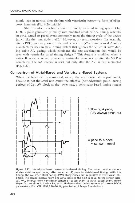
monly seen in normal sinus rhythm with ventricular ectopy—a form of oblig-atory hysteresis (Fig. 6.26, middle).
Other manufacturers have chosen to modify an atrial timing system. OneDDDR pulse generator primarily uses modified atrial, or AA, timing, wherebyan atrial sensed or paced event commonly resets the timing cycle of the device(much like the sinus node itself ).30 However, in certain situations (for example,after a PVC), an exception is made, and ventricular (VA) timing is used.Anothermanufacturer uses an atrial timing system that ignores the sensed R wave dur-ing stable AR pacing, which eliminates the rate acceleration that would be seen with ventricular-based timing designs.31 This feature is modified when anative R wave or sensed premature ventricular event occurs after the VRP iscompleted. The AA interval is reset but only after the AVI is first subtracted(Fig. 6.27).
Comparison of Atrial-Based and Ventricular-Based SystemsWhen the heart rate is considered, usually the ventricular rate is paramount,because it, not the atrial rate, causes the effective (hemodynamic) pulse. Duringperiods of 2 :1 AV block at the lower rate, a ventricular-based timing system
CARDIAC PACING AND ICDS
296
Figure 6.27. Ventricular-based versus atrial-based timing. The lower portion demon-strates atrial escape timing after an atrial (A) pace in atrial-based timing. With thistiming, the AVI after atrial pacing (PAV) always times out, regardless of ventricular inhi-bition. The escape interval from one atrial pace to the next is equal to the sensor inter-val. VAI, interval from ventricular sensed or paced event to atrial paced event. (FromHayes DL, Ketelson A, Levine PA, et al. Understanding timing systems of current DDDRpacemakers. Eur JCPE 1993;3:70–86. By permission of Mayo Foundation.)
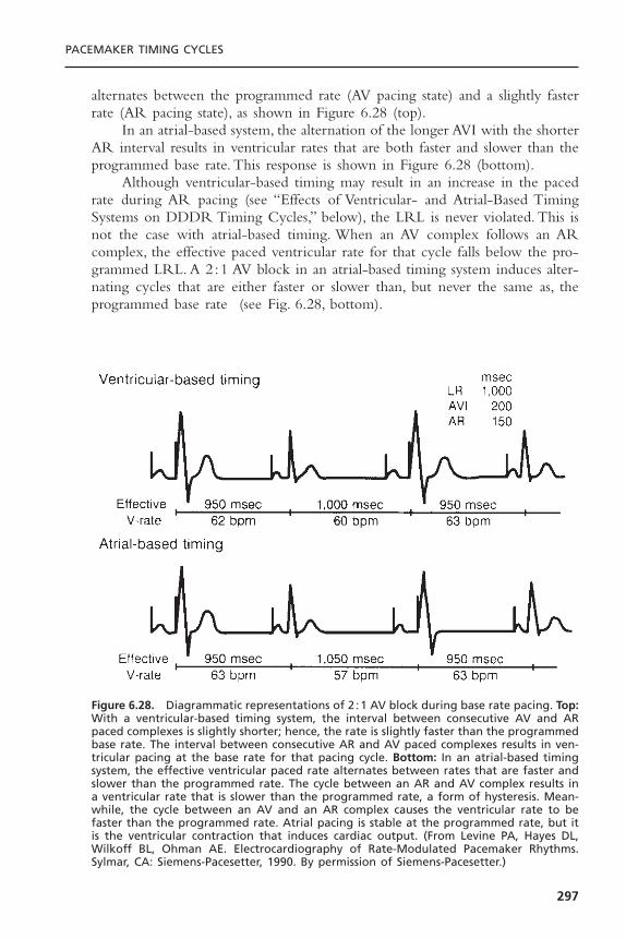
alternates between the programmed rate (AV pacing state) and a slightly fasterrate (AR pacing state), as shown in Figure 6.28 (top).
In an atrial-based system, the alternation of the longer AVI with the shorterAR interval results in ventricular rates that are both faster and slower than theprogrammed base rate. This response is shown in Figure 6.28 (bottom).
Although ventricular-based timing may result in an increase in the pacedrate during AR pacing (see “Effects of Ventricular- and Atrial-Based TimingSystems on DDDR Timing Cycles,” below), the LRL is never violated. This isnot the case with atrial-based timing. When an AV complex follows an ARcomplex, the effective paced ventricular rate for that cycle falls below the pro-grammed LRL. A 2 :1 AV block in an atrial-based timing system induces alter-nating cycles that are either faster or slower than, but never the same as, theprogrammed base rate (see Fig. 6.28, bottom).
PACEMAKER TIMING CYCLES
297
Figure 6.28. Diagrammatic representations of 2 :1 AV block during base rate pacing. Top:With a ventricular-based timing system, the interval between consecutive AV and ARpaced complexes is slightly shorter; hence, the rate is slightly faster than the programmedbase rate. The interval between consecutive AR and AV paced complexes results in ven-tricular pacing at the base rate for that pacing cycle. Bottom: In an atrial-based timingsystem, the effective ventricular paced rate alternates between rates that are faster andslower than the programmed rate. The cycle between an AR and AV complex results ina ventricular rate that is slower than the programmed rate, a form of hysteresis. Mean-while, the cycle between an AV and an AR complex causes the ventricular rate to befaster than the programmed rate. Atrial pacing is stable at the programmed rate, but itis the ventricular contraction that induces cardiac output. (From Levine PA, Hayes DL,Wilkoff BL, Ohman AE. Electrocardiography of Rate-Modulated Pacemaker Rhythms.Sylmar, CA: Siemens-Pacesetter, 1990. By permission of Siemens-Pacesetter.)

Interpretation of an ECG of a patient with a dual-chamber pacemaker ishelped by knowing whether the pacemaker has atrial-based or ventricular-basedtiming.With a ventricular-based timing system, a pair of calipers set to the VAIcan be used to measure backward from an atrial paced stimulus to the point ofventricular sensing, since a ventricular event, paced or sensed, always initiatesthe VAI.
A similar technique can be used in an atrial-based timing system, but onlywhen a sensed ventricular complex occurs after the VRP ends.The calipers mustbe set to the AA interval before measuring backward from the atrial paced eventthat follows a ventricular sensed event. If one were to misidentify an atrial-basedtiming system as a ventricular-based system, an otherwise normal rhythm mightbe misinterpreted as T-wave oversensing or some other form of oversensing (seeFig. 6.26, middle).
Sensor Input to Base Rate PacingThe sensor input to the pacing system temporarily adjusts the rate of the pace-maker. If the individual is active and rate modulation is enabled, the heart rateis determined by the faster of either the native rate or the sensor-determinedrate.The sensor rate behaves in a manner identical to the programmed base rate.If the native rate is faster than the base rate, the pacemaker is either inhibitedor tracks the atrial complexes. If the base rate is faster than the intrinsic rate,the heart rate is controlled by the pacemaker. Regardless of whether the pro-grammed base rate or the sensor rate is in effect, pacing is always atrial in adual-chamber pacing system.When the sensor input to the pacing system fluc-tuates, the rate changes.
Automatic Mode Switch Base RateOn the basis of the older literature on lone atrial fibrillation,32–35 higher heartrates are often needed to compensate for the loss of atrial transport.Thus, duringparoxysmal atrial fibrillation in a patient with high-grade AV block and a pace-maker with mode-switching capability, the resting heart rate during the non-tracking mode may be too low. This low intrinsic rate is of particular concernduring protracted periods of pacing in the nontracking mode. For this reason,the ability to independently program a resting pacemaker rate in effect whilethe mode switch algorithm is engaged has been introduced to some devices.The programmed base rate might be 60ppm during sinus rhythm and normalDDD function, whereas the base rate might be 80 to 90bpm during atrial fib-rillation with the system functioning in the DDI mode. If rate modulation werealso activated, any increase in sensor-driven rates would start at the appropriatebase for the functional pacing mode at the time.
Upper Rate BehaviorIn the DDD mode of operation, acceleration of the sinus rate results in thesensed P wave terminating the AEI and initiating an AVI, an effect known asP-wave synchronous ventricular pacing. (If the PR interval is shorter than the PV
CARDIAC PACING AND ICDS
298
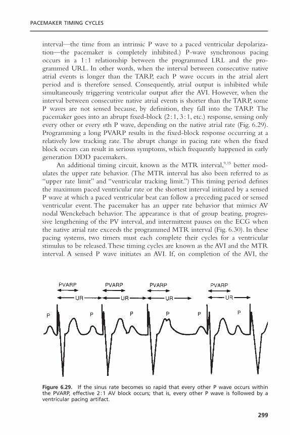
interval—the time from an intrinsic P wave to a paced ventricular depolariza-tion—the pacemaker is completely inhibited.) P-wave synchronous pacingoccurs in a 1 :1 relationship between the programmed LRL and the pro-grammed URL. In other words, when the interval between consecutive nativeatrial events is longer than the TARP, each P wave occurs in the atrial alertperiod and is therefore sensed. Consequently, atrial output is inhibited whilesimultaneously triggering ventricular output after the AVI. However, when theinterval between consecutive native atrial events is shorter than the TARP, someP waves are not sensed because, by definition, they fall into the TARP. Thepacemaker goes into an abrupt fixed-block (2 :1, 3 :1, etc.) response, sensing onlyevery other or every nth P wave, depending on the native atrial rate (Fig. 6.29).Programming a long PVARP results in the fixed-block response occurring at arelatively low tracking rate. The abrupt change in pacing rate when the fixedblock occurs can result in serious symptoms, which frequently happened in earlygeneration DDD pacemakers.
An additional timing circuit, known as the MTR interval,9,15 better mod-ulates the upper rate behavior. (The MTR interval has also been referred to as“upper rate limit” and “ventricular tracking limit.”) This timing period definesthe maximum paced ventricular rate or the shortest interval initiated by a sensedP wave at which a paced ventricular beat can follow a preceding paced or sensedventricular event. The pacemaker has an upper rate behavior that mimics AVnodal Wenckebach behavior. The appearance is that of group beating, progres-sive lengthening of the PV interval, and intermittent pauses on the ECG whenthe native atrial rate exceeds the programmed MTR interval (Fig. 6.30). In thesepacing systems, two timers must each complete their cycles for a ventricularstimulus to be released.These timing cycles are known as the AVI and the MTRinterval. A sensed P wave initiates an AVI. If, on completion of the AVI, the
PACEMAKER TIMING CYCLES
299
Figure 6.29. If the sinus rate becomes so rapid that every other P wave occurs withinthe PVARP, effective 2 :1 AV block occurs; that is, every other P wave is followed by aventricular pacing artifact.

MTR interval has been completed, a pacemaker stimulus is released at the programmed AVI. If the MTR interval has not yet been completed, the releaseof the ventricular output pulse is delayed until the MTR interval ends.This delay has the functional effect of lengthening the PV interval and placesthe ensuing ventricular paced beat closer to the next P wave. Both the PVARPand the MTR interval are initiated by a paced or sensed ventricular event.During Wenckebach upper rate behavior, a P wave eventually coincides withthe PVARP, is not sensed, and is therefore ignored by the pacemaker, whichresults in a relative pause.The MTR interval is then able to complete its timingperiod, which depends on the atrial rate and programmed base rate, so thateither the P wave that follows the unsensed P wave is tracked (restarting thecycle at the programmed AVI) or the pause is terminated by AV sequentialpacing.
Thus, upper rate behavior can demonstrate Wenckebach-like behavior orgo into abrupt fixed block (e.g., 2 :1). It demonstrates 2 :1 block behavior whenthe P wave falls into the TARP. If the MTR interval is longer than the TARP(TARP = AVI + PVARP), then Wenckebach-like behavior occurs. This can besummarized by the following equation: Wenckebach interval = MTR interval- TARP.
Therefore, if a positive number results, Wenckebach-like behavior occurs.In contrast, if a negative number results, fixed 2 :1 AV block occurs. For example,if a patient’s pacemaker is programmed to an AVI of 250 milliseconds, a PVARPof 225 milliseconds, and an MTR of 400 milliseconds, by the above equationthe Wenckebach interval is 400 - (250 + 225), or a negative number. There-fore, when the atrial rate reaches 401 milliseconds, a 2 :1 AV upper rate response
CARDIAC PACING AND ICDS
300
Figure 6.30. In the DDD pacing mode, the programmed upper rate limit (UR) cannot beviolated regardless of the sinus rate. When a P wave is sensed after the PVARP, the AVIis initiated. If, however, delivering a ventricular pacing artifact at the end of the AVIwould violate the UR, the ventricular pacing artifact cannot be delivered. The pacemakerwould wait until completion of the UR and then deliver the ventricular pacing artifact.This action would result in a prolonged AVI.
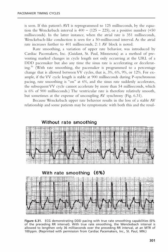
is seen. If this patient’s AVI is reprogrammed to 125 milliseconds, by the equa-tion the Wenckebach interval is 400 - (125 - 225), or a positive number (+50milliseconds). In the latter instance, when the atrial rate is 351 milliseconds,Wenckebach-like conduction is seen for a 50-millisecond interval. As the atrialrate increases further to 401 milliseconds, 2 :1 AV block is noted.
Rate smoothing, a variation of upper rate behavior, was introduced byCardiac Pacemakers, Inc. (Guidant, St. Paul, Minnesota) as a method of pre-venting marked changes in cycle length not only occurring at the URL of aDDD pacemaker but also any time the sinus rate is accelerating or decelerat-ing.36 (With rate smoothing, the pacemaker is programmed to a percentagechange that is allowed between VV cycles, that is, 3%, 6%, 9%, or 12%. For ex-ample, if the VV cycle length is stable at 900 milliseconds during P-synchronouspacing, rate smoothing is “on” at 6%, and the sinus rate suddenly accelerates,the subsequent VV cycle cannot accelerate by more than 54 milliseconds, whichis 6% of 900 milliseconds.) The ventricular rate is therefore relatively smooth,but sometimes at the expense of uncoupling AV synchrony (Fig. 6.31).
Because Wenckebach upper rate behavior results in the loss of a stable AVrelationship and some patients may be symptomatic with both this and the resul-
PACEMAKER TIMING CYCLES
301
Figure 6.31. ECG demonstrating DDD pacing with true rate smoothing capabilities (6%of the preceding RR interval). With true rate smoothing, the Wenckebach interval isallowed to lengthen only 36 milliseconds over the preceding RR interval, at an MTR of100ppm. (Reprinted with permission from Cardiac Pacemakers, Inc., St. Paul, MN.)

tant pauses that occur when a P wave coincides with the PVARP and is nottracked, another upper rate behavior, fallback, is available in some devices.Whenthe atrial rate exceeds the programmed MTR, the pacemaker continues to senseatrial activity but uncouples the native atrial rhythm from the ventricular pacedcomplexes. The ventricular paced rate then slowly and progressively decreasesto either an intermediate rate or the programmed base rate. This arrangementavoids the abrupt pauses that occur with both the Wenckebach and the fixed-block behaviors. When the atrial rate slows below either the MTR or the fall-back rate, depending on the design of the system, the desired AV relationshipis restored.
Mode SwitchingMode switching refers to the ability of the pacemaker to automatically changefrom one mode to another in response to an inappropriately rapid atrialrhythm.37 With mode switching, when the pacemaker is functioning in theDDDR mode, the algorithm automatically reprograms the pacemaker to theVVIR mode if specific criteria for a pathologic atrial rhythm are met. Modeswitching is particularly useful for patients with paroxysmal supraventricularrhythm disturbances. In the DDD or DDDR pacing mode, if a supraventricu-lar rhythm disturbance occurs and the pathologic atrial rhythm is sensed by thepacemaker, rapid ventricular pacing may occur (Fig. 6.32). Any pacing modethat eliminates tracking of the pathologic rhythm, for example, DDI, DDIR,DVI, or DVIR, also eliminates the ability to track normal sinus rhythm, whichis usually the predominant rhythm. Mode switching avoids this limitation (Fig.6.33).
Refinement of mode-switching algorithms has made this a successfulfeature (Fig. 6.34).38 Mode switching functions by measuring intervals between
CARDIAC PACING AND ICDS
302
Figure 6.32. Resting ECG tracing demonstrating AV sequential pacing at lower rate (55ppm) followed by paroxysmal atrial flutter with ventricular tracking at MTR (110ppm).Diagram shows atrial paced events (AP), atrial sensed events (AS), and ventricular pacedevents (VP), with the PVARP noted by the rectangle. Short, unlabeled ticks representatrial activity that occurs in the PVARP and is not sensed. (Diagram is based on MarkerChannel, Medtronic, Inc., Minneapolis, MN.) (From Levine PA, Hayes DL, Wilkoff BL,Ohman AE. Electrocardiography of rate-modulated pacemaker rhythms. Sylmar, CA:Siemens-Pacesetter, 1990. By permission of Siemens-Pacesetter.)
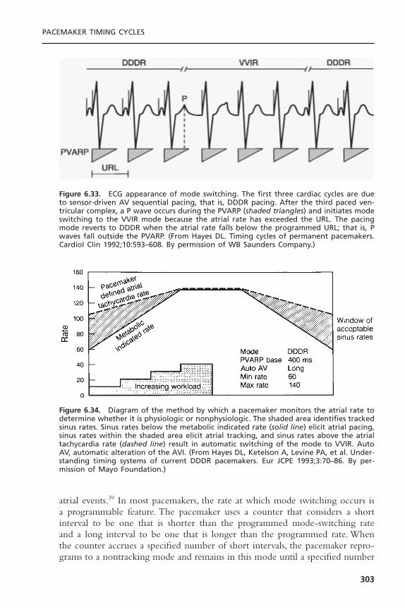
atrial events.39 In most pacemakers, the rate at which mode switching occurs isa programmable feature. The pacemaker uses a counter that considers a shortinterval to be one that is shorter than the programmed mode-switching rateand a long interval to be one that is longer than the programmed rate. Whenthe counter accrues a specified number of short intervals, the pacemaker repro-grams to a nontracking mode and remains in this mode until a specified number
PACEMAKER TIMING CYCLES
303
Figure 6.33. ECG appearance of mode switching. The first three cardiac cycles are dueto sensor-driven AV sequential pacing, that is, DDDR pacing. After the third paced ven-tricular complex, a P wave occurs during the PVARP (shaded triangles) and initiates modeswitching to the VVIR mode because the atrial rate has exceeded the URL. The pacingmode reverts to DDDR when the atrial rate falls below the programmed URL; that is, Pwaves fall outside the PVARP. (From Hayes DL. Timing cycles of permanent pacemakers.Cardiol Clin 1992;10:593–608. By permission of WB Saunders Company.)
Figure 6.34. Diagram of the method by which a pacemaker monitors the atrial rate todetermine whether it is physiologic or nonphysiologic. The shaded area identifies trackedsinus rates. Sinus rates below the metabolic indicated rate (solid line) elicit atrial pacing,sinus rates within the shaded area elicit atrial tracking, and sinus rates above the atrialtachycardia rate (dashed line) result in automatic switching of the mode to VVIR. AutoAV, automatic alteration of the AVI. (From Hayes DL, Ketelson A, Levine PA, et al. Under-standing timing systems of current DDDR pacemakers. Eur JCPE 1993;3:70–86. By per-mission of Mayo Foundation.)

of long intervals have occurred and altered the counter, at which point modeswitching reverts.The nontracking mode to which the mode switch occurs maybe a programmable option.
Variations on the mode-switching theme are too numerous to detail in thischapter. One should become familiar with the nuances of the mode-switchingalgorithms used.40 Key to the implementation of mode switching is the pace-maker’s ability to recognize high atrial rates.As discussed in the section on upperrate behavior, the TARP limits the atrial rate that can be detected and tracked.If rapid atrial rates are to be detected, identifying atrial events that occur duringthe refractory period is essential. In the modern dual-chamber pacemaker, thisperiod includes the terminal portion of the AV delay and the latter portion ofthe PVARP. As noted for single-chamber refractory periods, the PVARP hasabsolute and relative portions. The absolute portion is the first part of thePVARP, and it is termed the postventricular atrial blanking (PVAB) period.The purpose of this timing period is to prevent sensing of the far-field R wave.The ventricular depolarization is a relatively large signal. To ensure sensing ofpathologic atrial tachyarrhythmias whose signal amplitudes may fluctuate andmay be very small, the atrial channel is usually programmed to a sensitive value.This combination predisposes to detection of ventricular signals on the atrialchannel. The pacemaker may label these “P” waves and thus respond as if theatrial rate were high when the rhythm is actually normal sinus rhythm.41–43 Theresult is a form of double counting, resulting in “false” mode switching. Toprevent far-field R-wave sensing, a period of absolute refractoriness corre-sponding to the expected timing of this event forms the first portion of thePVARP. In devices with first-generation mode-switching algorithms, PVAB wasnot even mentioned because it was not programmable. In dual-chamber devicesfrom virtually all manufacturers as of 2000, PVAB is programmable from 50 to250 milliseconds. There is an inverse relationship between the duration of thePVAB and the detection of atrial arrhythmia, with the shorter PVABs allowingdetection of higher atrial rates (increased sensitivity to atrial tachyarrhythmias).However, increasing the PVAB increases the specificity of rhythm detection andminimizes inappropriate mode switching.
Because a far-field R wave may be detected before the depolarization issensed by the ventricular channel of the pacemaker (Fig. 6.35), another timingcircuit, preventricular atrial blanking (pre-VAB), may be helpful. Although the siteof native ventricular depolarization cannot be predicted, the algorithm sets upa monitoring interval following the detected atrial event. This programmableperiod varies from 0 to 60 milliseconds. If an R wave is detected during thepre-VAB interval, the atrial event is labeled a far-field R wave and is not usedin the calculation of high atrial rates.
Atrial Flutter ResponseAn algorithm to specifically respond to atrial flutter is available in some pace-makers. Such an algorithm is designed to prevent pacing into the atrial vulner-
CARDIAC PACING AND ICDS
304
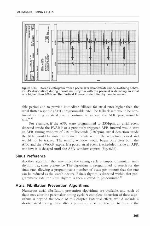
able period and to provide immediate fallback for atrial rates higher than theatrial flutter response (AFR) programmable rate.The fallback rate would be con-tinued as long as atrial events continue to exceed the AFR programmablerate.44,45
For example, if the AFR were programmed to 250bpm, an atrial eventdetected inside the PVARP or a previously triggered AFR interval would startan AFR timing window of 240 milliseconds (250bpm). Atrial detection insidethe AFR would be noted as “sensed” events within the refractory period andwould not be tracked. The sensing window would begin only after both theAFR and the PVARP expire. If a paced atrial event is scheduled inside an AFRwindow, it is delayed until the AFR window expires (Fig. 6.36).
Sinus PreferenceAnother algorithm that may affect the timing cycle attempts to maintain sinusrhythm, i.e., sinus preference. The algorithm is programmed to search for thesinus rate, allowing a programmable number of beats per minute that the ratecan be reduced as the search occurs. If sinus rhythm is detected within that pro-grammable rate, the sinus rhythm is then allowed to predominate.46
Atrial Fibrillation Prevention AlgorithmsNumerous atrial fibrillation prevention algorithms are available, and each ofthese may alter the pacemaker timing cycle.A complete discussion of these algo-rithms is beyond the scope of this chapter. Potential effects would include ashorter atrial pacing cycle after a premature atrial contraction to prevent the
PACEMAKER TIMING CYCLES
305
Figure 6.35. Stored electrogram from a pacemaker demonstrates mode-switching behav-ior (AV dissociation) during normal sinus rhythm with the pacemaker detecting an atrialrate higher than 200bpm. The far-field R wave is identified by double arrows.
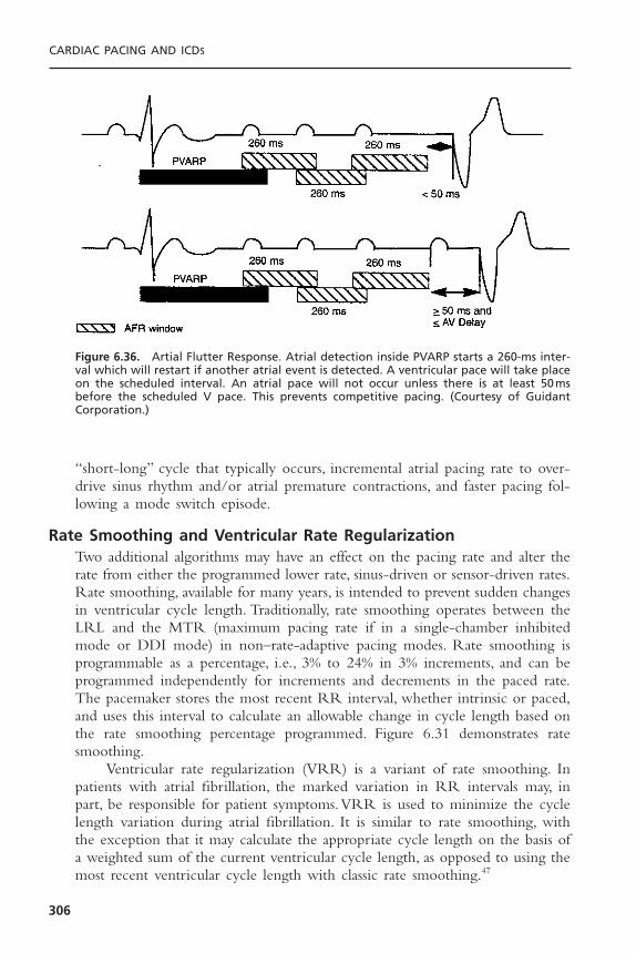
“short-long” cycle that typically occurs, incremental atrial pacing rate to over-drive sinus rhythm and/or atrial premature contractions, and faster pacing fol-lowing a mode switch episode.
Rate Smoothing and Ventricular Rate RegularizationTwo additional algorithms may have an effect on the pacing rate and alter therate from either the programmed lower rate, sinus-driven or sensor-driven rates.Rate smoothing, available for many years, is intended to prevent sudden changesin ventricular cycle length. Traditionally, rate smoothing operates between theLRL and the MTR (maximum pacing rate if in a single-chamber inhibitedmode or DDI mode) in non–rate-adaptive pacing modes. Rate smoothing isprogrammable as a percentage, i.e., 3% to 24% in 3% increments, and can beprogrammed independently for increments and decrements in the paced rate.The pacemaker stores the most recent RR interval, whether intrinsic or paced,and uses this interval to calculate an allowable change in cycle length based onthe rate smoothing percentage programmed. Figure 6.31 demonstrates ratesmoothing.
Ventricular rate regularization (VRR) is a variant of rate smoothing. Inpatients with atrial fibrillation, the marked variation in RR intervals may, inpart, be responsible for patient symptoms.VRR is used to minimize the cyclelength variation during atrial fibrillation. It is similar to rate smoothing, withthe exception that it may calculate the appropriate cycle length on the basis ofa weighted sum of the current ventricular cycle length, as opposed to using themost recent ventricular cycle length with classic rate smoothing.47
CARDIAC PACING AND ICDS
306
Figure 6.36. Artial Flutter Response. Atrial detection inside PVARP starts a 260-ms inter-val which will restart if another atrial event is detected. A ventricular pace will take placeon the scheduled interval. An atrial pace will not occur unless there is at least 50msbefore the scheduled V pace. This prevents competitive pacing. (Courtesy of Guidant Corporation.)
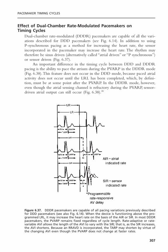
Effect of Dual-Chamber Rate-Modulated Pacemakers on Timing Cycles
Dual-chamber rate-modulated (DDDR) pacemakers are capable of all the vari-ations described for DDD pacemakers (see Fig. 6.14). In addition to using P-synchronous pacing as a method for increasing the heart rate, the sensor incorporated in the pacemaker may increase the heart rate. The rhythm maytherefore be sinus driven (alternatively called “atrial driven” or “P synchronous”)or sensor driven (Fig. 6.37).
An important difference in the timing cycle between DDD and DDDRpacing is the ability to pace the atrium during the PVARP in the DDDR mode(Fig. 6.38).This feature does not occur in the DDD mode, because paced atrialactivity does not occur until the LRL has been completed, which, by defini-tion, must be at some point after the PVARP. In the DDDR mode, however,even though the atrial sensing channel is refractory during the PVARP, sensor-driven atrial output can still occur (Fig. 6.38).48
PACEMAKER TIMING CYCLES
307
Figure 6.37. DDDR pacemakers are capable of all pacing variations previously describedfor DDD pacemakers (see also Fig. 6.14). When the device is functioning above the pro-grammed LRL, it may increase the heart rate on the basis of the AIR or SIR. In most DDDRpacemakers, the PVARP remains fixed regardless of cycle length. Rate-adaptive or rate-variable AVI allows the length of the AVI to vary with the SIR; that is, as the SIR increases,the AVI shortens. Because an RRAVD is incorporated, the TARP may shorten by virtue ofthe changing AVI even though the PVARP does not change at faster rates.
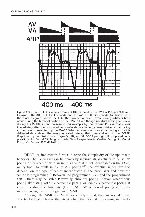
DDDR pacing systems further increase the complexity of the upper ratebehavior. The pacemaker can be driven by intrinsic atrial activity to cause PVpacing or by a sensor with an input signal that is not identifiable on the ECG,or by both, to result in AV or AR pacing.3,29 The eventual upper rate alsodepends on the type of sensor incorporated in the pacemaker and how thesensor is programmed.49 Between the programmed LRL and the programmedURL, there may be stable P-wave synchronous pacing, P-wave synchronouspacing alternating with AV sequential pacing, or stable AV sequential pacing atrates exceeding the base rate (Fig. 6.39).50 AV sequential pacing rates mayincrease as high as the programmed MSR.
Although the MSR and MTR are closely related, they are not identical.The tracking rate refers to the rate at which the pacemaker is sensing and track-
CARDIAC PACING AND ICDS
308
Figure 6.38. In this ECG example from a DDDR pacemaker, the MSR is 150ppm (400 mil-liseconds), the ARP is 350 milliseconds, and the AVI is 100 milliseconds. As illustrated inthe block diagrams above the ECG, the two sensor-driven atrial pacing artifacts bothoccur during the terminal portion of the PVARP. Even though no atrial sensing can occurduring the PVARP, as can be seen in this example by the intrinsic P wave that occursimmediately after the first paced ventricular depolarization, a sensor-driven atrial pacingartifact is not prevented by the PVARP. Whether a sensor-driven atrial pacing artifact isdelivered depends on the sensor-indicated rate at that time and not on the PVARP.(Reprinted by permission from Hayes DL, Higano ST. DDDR pacing: follow-up and com-plications. In: Barold SS, Mugica J, eds. New Perspectives in Cardiac Pacing, 2. MountKisco, NY: Futura, 1991:473–491.)
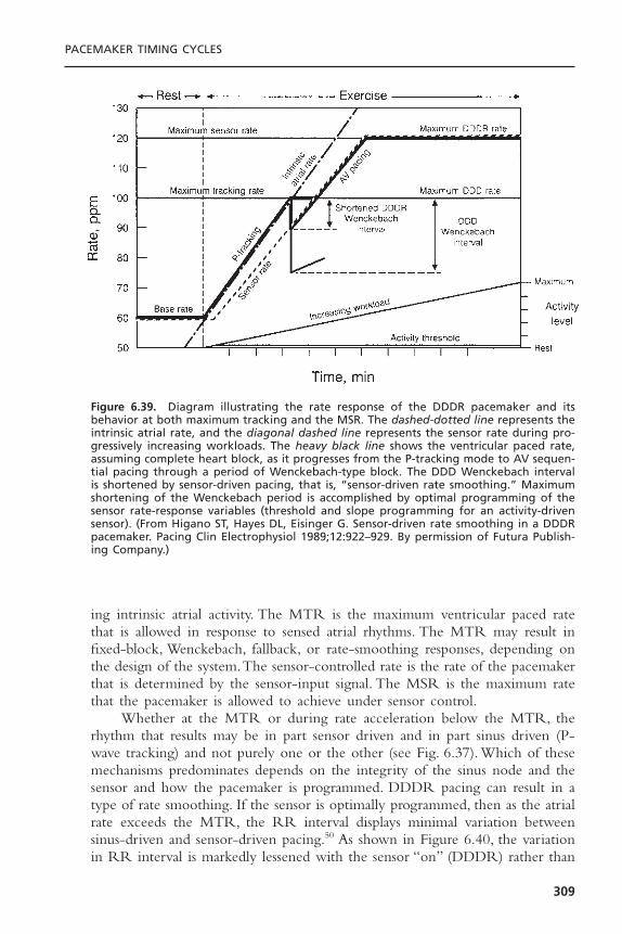
ing intrinsic atrial activity. The MTR is the maximum ventricular paced ratethat is allowed in response to sensed atrial rhythms. The MTR may result infixed-block, Wenckebach, fallback, or rate-smoothing responses, depending onthe design of the system.The sensor-controlled rate is the rate of the pacemakerthat is determined by the sensor-input signal. The MSR is the maximum ratethat the pacemaker is allowed to achieve under sensor control.
Whether at the MTR or during rate acceleration below the MTR, therhythm that results may be in part sensor driven and in part sinus driven (P-wave tracking) and not purely one or the other (see Fig. 6.37). Which of thesemechanisms predominates depends on the integrity of the sinus node and thesensor and how the pacemaker is programmed. DDDR pacing can result in atype of rate smoothing. If the sensor is optimally programmed, then as the atrialrate exceeds the MTR, the RR interval displays minimal variation betweensinus-driven and sensor-driven pacing.50 As shown in Figure 6.40, the variationin RR interval is markedly lessened with the sensor “on” (DDDR) rather than
PACEMAKER TIMING CYCLES
309
Figure 6.39. Diagram illustrating the rate response of the DDDR pacemaker and itsbehavior at both maximum tracking and the MSR. The dashed-dotted line represents theintrinsic atrial rate, and the diagonal dashed line represents the sensor rate during pro-gressively increasing workloads. The heavy black line shows the ventricular paced rate,assuming complete heart block, as it progresses from the P-tracking mode to AV sequen-tial pacing through a period of Wenckebach-type block. The DDD Wenckebach intervalis shortened by sensor-driven pacing, that is, “sensor-driven rate smoothing.” Maximumshortening of the Wenckebach period is accomplished by optimal programming of thesensor rate-response variables (threshold and slope programming for an activity-drivensensor). (From Higano ST, Hayes DL, Eisinger G. Sensor-driven rate smoothing in a DDDRpacemaker. Pacing Clin Electrophysiol 1989;12:922–929. By permission of Futura Publish-ing Company.)

“passive” (DDD) mode. In the DDDR mode, the RR interval is allowed tolengthen only as much as the difference between the MTR and the activitysensor rate interval. For example, if a device is programmed to a P-wave track-ing limit of 120ppm and the patient’s atrial rate exceeds this, then the pace-maker operates in a Wenckebach-type block. If the sensor-indicated rate at thistime is 100ppm, the paced rate decreases from 120ppm (500 milliseconds) toan AV sequential paced rate of 100ppm (600 milliseconds) for the Wenckebachcycle and then returns to P-wave tracking at a rate of 120ppm. This situationusually shortens the DDD Wenckebach interval, but this interval depends onthe atrial rate and the programmed values for the MTR and the TARP.
Maximal sensor-driven rate smoothing requires optimal programming ofthe sensor variable. If the rate-responsive circuitry is programmed to mimic thenative atrial rate, the paced ventricular rate cannot demonstrate the 2 :1 orWenckebach-type behavior. Conversely, if the rate-responsive circuitry is pro-grammed to low levels of sensor-driven pacing, little or no rate smoothingoccurs (Figs. 6.39 and 6.41). Figure 6.40 shows the sensor “passive” (DDD)
CARDIAC PACING AND ICDS
310
Figure 6.40. This diagram illustrates the difference in DDD and DDDR behavior whenthe intrinsic atrial rate increases. In the upper panel, DDD pacing is illustrated. The sensedatrial events (AS) occur increasingly closer to the PVARP, which is programmed to 225milliseconds (shown by the shaded triangles) until the fifth AS event (*) occurs at 210milliseconds after the preceding ventricular paced event (VP) and within the PVARP andis not sensed. This is followed by another AS and VP after the programmed AVI of 150milliseconds. The resultant cycle length is 810 milliseconds, significantly longer than thepreceding cycles of 480 milliseconds. In the lower panel, DDDR pacing is illustrated. Theintervals are programmed to the same values as in the upper panel. When the fifth ASevent occurs within the PVARP, it is, by definition, not sensed. However, the escape eventis a sensor-driven atrial pacing artifact followed by a VP after the AVI. The sensor-indi-cated cycle length is 545 milliseconds. Therefore, only a 65-millisecond difference existsbetween the programmed URL and the sensor-indicated rate—a minor difference in cyclelengths. (Modified from Markowitz HT. Dual chamber rate responsive pacing [DDDR] provides physiologic upper rate behavior. PhysioPace 1990;4:1–4. By permission of Med-tronic.)
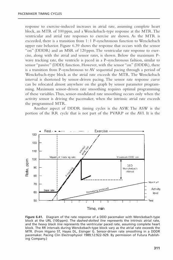
response to exercise-induced increases in atrial rate, assuming complete heartblock, an MTR of 100ppm, and a Wenckebach-type response at the MTR.Theventricular and atrial rate responses to exercise are shown. As the MTR isexceeded, there is a transition from 1 :1 P-synchronous function to Wenckebachupper rate behavior. Figure 6.39 shows the response that occurs with the sensor“on” (DDDR) and an MSR of 120ppm.The ventricular rate response to exer-cise, along with the atrial and sensor rates, is shown. Below the maximum P-wave tracking rate, the ventricle is paced in a P-synchronous fashion, similar tosensor “passive” (DDD) function. However, with the sensor “on” (DDDR), thereis a transition from P-synchronous to AV sequential pacing through a period ofWenckebach-type block as the atrial rate exceeds the MTR. The Wenckebachinterval is shortened by sensor-driven pacing. The sensor rate response curvecan be relocated almost anywhere on the graph by sensor parameter program-ming. Maximum sensor-driven rate smoothing requires optimal programmingof these variables.Thus, sensor-modulated rate smoothing occurs only when theactivity sensor is driving the pacemaker, when the intrinsic atrial rate exceedsthe programmed MTR.
Another aspect of DDDR timing cycles is the ASW. The ASW is theportion of the RR cycle that is not part of the PVARP or the AVI. It is the
PACEMAKER TIMING CYCLES
311
Figure 6.41. Diagram of the rate response of a DDD pacemaker with Wenckebach-typeblock at the URL (100ppm). The dashed-dotted line represents the intrinsic atrial rate,and the heavy black line represents the ventricular paced rate, assuming complete heartblock. The RR intervals during Wenckebach-type block vary as the atrial rate exceeds theMTR. (From Higano ST, Hayes DL, Eisinger G. Sensor-driven rate smoothing in a DDDRpacemaker. Pacing Clin Electrophysiol 1989;12:922–929. By permission of Futura Publish-ing Company.)
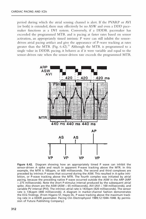
period during which the atrial sensing channel is alert. If the PVARP or AVI(or both) is extended, there may effectively be no ASW and even a DDD pace-maker functions as a DVI system. Conversely, if a DDDR pacemaker hasexceeded the programmed MTR and is pacing at faster rates based on sensoractivation, an appropriately timed intrinsic P wave can still inhibit the sensor-driven atrial pacing artifact and give the appearance of P-wave tracking at ratesgreater than the MTR (Fig. 6.42).51 Although the MTR is programmed to asingle value in DDDR pacing, it behaves as if it were variable and equal to thesensor-driven rate when the sensor-driven rate exceeds the programmed MTR
CARDIAC PACING AND ICDS
312
Figure 6.42. Diagram showing how an appropriately timed P wave can inhibit thesensor-driven A spike and result in apparent P-wave tracking above the MTR. In thisexample, the MTR is 100ppm, or 600 milliseconds. The second and third complexes arepreceded by intrinsic P waves that occurred during the ASW. This resulted in A-spike inhi-bition, or P-wave tracking above the MTR. The fourth complex was initiated by atrialpacing, because the preceding native P wave occurred outside the ASW in the ARP (ARP= 275 milliseconds). Note the short P-stimulus interval produced by the subsequent atrialspike. Also shown are the ASW (ASW = 65 milliseconds), AVI (AVI = 100 milliseconds), andvariable PV interval (PVI). The intrinsic atrial rate is 143bpm (420 milliseconds). The sensorrate is 136ppm (440 milliseconds). A diagram in marker-channel fashion demonstratesthe ECG findings. (From Higano ST, Hayes DL. P wave tracking above the maximum track-ing rate in a DDDR pacemaker. Pacing Clin Electrophysiol 1989;12:1044–1048. By permis-sion of Futura Publishing Company.)

if a P wave occurs during the ASW to inhibit output of an atrial pacing artifact.
Effects of Ventricular- and Atrial-Based Timing Systems on DDDR Timing Cycles
As noted previously, the “timing system” may affect the timing cycle. In a ven-tricular-based timing system, the effective atrial paced rate theoretically may beconsiderably higher than the programmed MSR if AR conduction were present(Fig. 6.43, top).3 Assuming that the maximum sensor-controlled rate is 150ppm(a cycle length of 400 milliseconds), the AEI with a programmed AVI of 200milliseconds is also 200 milliseconds. If AV conduction were intact such that theAR interval was 150 milliseconds, the actual pacing interval would be ARI +AEI, or 150 + 200 milliseconds, or 350 milliseconds. A cycle length of 350 mil-liseconds equals 171ppm, which is markedly higher than the programmed MSRof 150ppm. Although this potentially achievable faster rate may not be a
PACEMAKER TIMING CYCLES
313
Figure 6.43. Effect of different timing systems on MSR with intact stable AV nodal con-duction (AR pacing). Top: In a ventricular-based timing system, there is a considerabletheoretical increase in the paced atrial rate exceeding that programmed by the physi-cian. In the example shown, even though the MSR programmed is 150ppm, or 400 mil-liseconds, the effective pacing rate achieved is 171ppm, because the effective pacing rateis the sum of the ARI and the AEI; that is, 150 + 200 = 350 milliseconds (171ppm). Middle:In an atrial-based system, the R wave sensed during the AVI alters the basic timing duringstable AR pacing. This results in atrial pacing at the sensor-indicated rate. Bottom: Theaddition of an RRAVD to a ventricular-based timing system minimizes the increase in thepaced atrial rate above the programmed sensor-indicated rate. (From Levine PA, HayesDL, Wilkoff BL, Ohman AE. Electrocardiography of Rate-Modulated Pacemaker Rhythms.Sylmar, CA: Siemens-Pacesetter, 1990. By permission of Siemens-Pacesetter.)

problem or may even be advantageous for some patients, it could create prob-lems for other patients (Fig. 6.43, middle).
Rate acceleration can also be minimized in a DDDR ventricular-basedtiming system by incorporating a rate-responsive AV delay (RRAVD).29,52 Asthe sinus or sensor-driven rate progressively increases, RRAVD causes the PVand AVIs to progressively shorten (Fig. 6.43, bottom). Shortening the AVI withRRAVD results in a shorter TARP (shorter AVI + PVARP), which increasesthe intrinsic atrial rate that can be sensed and reduces the likelihood of both afixed-block upper rate response and functional atrial undersensing. It also min-imizes the chance of an inappropriately long PV interval at the higher rate,which may occur with a fixed AV delay when the fixed AV delay is programmedappropriately for lower rate behavior. In this case, the AV delay may be too longat higher rates. In a DDDR system, when the AVI shortens, the ventricular ratedrive is held to that governed by the sensor so that the time subtracted fromthe AVI is added to the AEI. Thus, at a rate of 150ppm and pacing interval of400 milliseconds, if the RRAVD causes the AVI to shorten by 75 millisecondsfrom an initially programmed AVI of 200 milliseconds, then the AVI shortensto 125 milliseconds. Because the overall ventricular timing is held constant, the75 milliseconds subtracted from the AVI is added to the AEI, increasing it to275 milliseconds.
The RRAVD provides a more physiologic AVI at the faster rate and min-imizes the degree of rate increase over the programmed MSR if AR conduc-tion is intact. Assuming that the rate is 150ppm and the initial AVI is 200milliseconds, the RRAVD is 125 milliseconds, resulting in AV sequential pacingat the sensor programmed rate when the AR interval is 140 milliseconds. Ifintact AV conduction is present at 120 milliseconds, the overall shortening ofthe pacing interval is only 5 milliseconds more than that seen at 150bpm, a rateof 152bpm (Fig. 6.43, bottom).
Another option is extending the VAI as needed to control the AA pacingrate according to the programmed MSR (Fig. 6.44). This extension results inadaptive-rate pacing, regardless of AV conduction status, which is equal to, butdoes not exceed, the desired MSR.
ENDLESS-LOOP TACHYCARDIAEndless-loop tachycardia (ELT) is not a portion of the timing cycle, but under-standing the timing cycle of dual-chamber pacing is crucial to understandingELT, and vice versa. ELT has also been referred to as “pacemaker-mediatedtachycardia” (PMT), “pacemaker-mediated reentry tachycardia,” and “pacemakercircus movement tachycardia.”9 ELT has been defined as a reentry arrhythmiain which the dual-chamber pacemaker acts as the anterograde limb of the tachy-cardia and the natural pathway acts as the retrograde limb.53,54
If AV synchrony is uncoupled—that is, if the P wave is displaced from itsnormal relation to the QRS complex—the subsequent ventricular event mayresult in retrograde atrial excitation if retrograde or VA conduction is intact.53,54
CARDIAC PACING AND ICDS
314
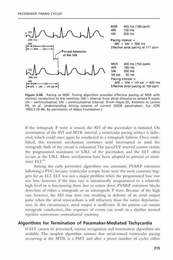
If the retrograde P wave is sensed, the AVI of the pacemaker is initiated. Ontermination of the AVI and MTR interval, a ventricular pacing artifact is deliv-ered, which could once again be conducted in a retrograde fashion. Once estab-lished, this reentrant mechanism continues until interrupted or until theretrograde limb of the circuit is exhausted.The paced VV interval cannot violatethe programmed maximum or URL of the pacemaker, and the ELT oftenoccurs at the URL. Many mechanisms have been adopted to prevent or mini-mize ELT.55
Among the early preventive algorithms was automatic PVARP extensionfollowing a PVC, because ventricular ectopic beats were the most common trig-gers for an ELT. ELT was not a major problem when the programmed base ratewas low; however, if the base rate is intentionally programmed to a relativelyhigh level or is functioning there due to sensor drive, PVARP extension blocksdetection of either a retrograde or an anterograde P wave. Because of the highrate, however, the AEI may time out, resulting in delivery of an atrial outputpulse when the atrial myocardium is still refractory from the native depolariza-tion. In this circumstance, atrial output is ineffective. If the patient can sustainretrograde conduction, this sequence of events can result in a rhythm termedrepetitive nonreentrant ventriculoatrial synchrony.
Algorithms for Termination of Pacemaker-Mediated TachycardiaIf ELT cannot be prevented, various recognition and termination algorithms areavailable. The simplest algorithm assumes that atrial-sensed ventricular pacingoccurring at the MTR is a PMT and after a preset number of cycles either
PACEMAKER TIMING CYCLES
315
Figure 6.44. Pacing at MSR. Timing algorithm provides effective pacing at MSR withintrinsic conduction to the ventricle. ARI = interval from atrial stimulus to sensed R wave;VA = ventriculoatrial; VAI = ventriculoatrial interval. (From Hayes DL, Ketelson A, LevinePA, et al. Understanding timing systems of current DDDR pacemakers. Eur JCPE1993;3:70–86. By permission of Mayo Foundation.)
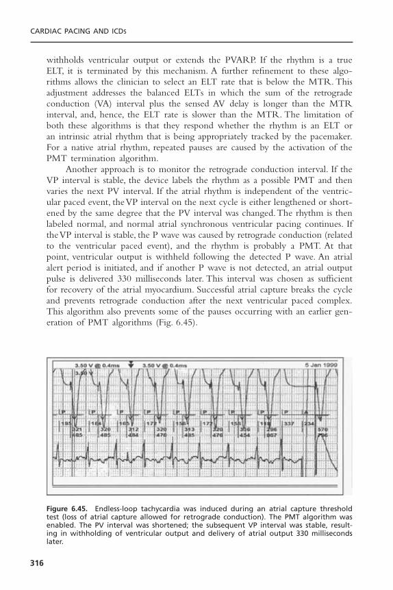
withholds ventricular output or extends the PVARP. If the rhythm is a trueELT, it is terminated by this mechanism. A further refinement to these algo-rithms allows the clinician to select an ELT rate that is below the MTR. Thisadjustment addresses the balanced ELTs in which the sum of the retrogradeconduction (VA) interval plus the sensed AV delay is longer than the MTRinterval, and, hence, the ELT rate is slower than the MTR. The limitation ofboth these algorithms is that they respond whether the rhythm is an ELT oran intrinsic atrial rhythm that is being appropriately tracked by the pacemaker.For a native atrial rhythm, repeated pauses are caused by the activation of thePMT termination algorithm.
Another approach is to monitor the retrograde conduction interval. If theVP interval is stable, the device labels the rhythm as a possible PMT and thenvaries the next PV interval. If the atrial rhythm is independent of the ventric-ular paced event, the VP interval on the next cycle is either lengthened or short-ened by the same degree that the PV interval was changed.The rhythm is thenlabeled normal, and normal atrial synchronous ventricular pacing continues. Ifthe VP interval is stable, the P wave was caused by retrograde conduction (relatedto the ventricular paced event), and the rhythm is probably a PMT. At thatpoint, ventricular output is withheld following the detected P wave. An atrialalert period is initiated, and if another P wave is not detected, an atrial outputpulse is delivered 330 milliseconds later. This interval was chosen as sufficientfor recovery of the atrial myocardium. Successful atrial capture breaks the cycleand prevents retrograde conduction after the next ventricular paced complex.This algorithm also prevents some of the pauses occurring with an earlier gen-eration of PMT algorithms (Fig. 6.45).
CARDIAC PACING AND ICDS
316
Figure 6.45. Endless-loop tachycardia was induced during an atrial capture thresholdtest (loss of atrial capture allowed for retrograde conduction). The PMT algorithm wasenabled. The PV interval was shortened; the subsequent VP interval was stable, result-ing in withholding of ventricular output and delivery of atrial output 330 millisecondslater.
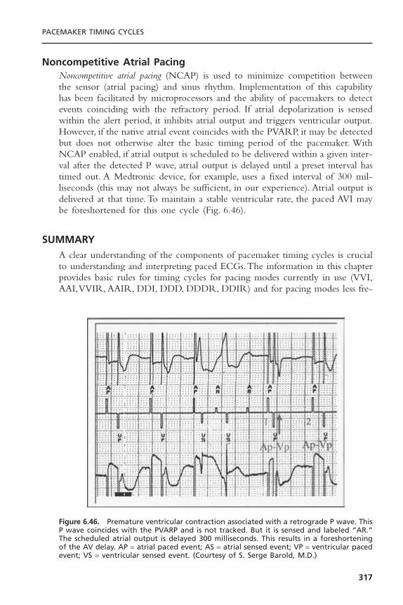
Noncompetitive Atrial PacingNoncompetitive atrial pacing (NCAP) is used to minimize competition betweenthe sensor (atrial pacing) and sinus rhythm. Implementation of this capabilityhas been facilitated by microprocessors and the ability of pacemakers to detectevents coinciding with the refractory period. If atrial depolarization is sensedwithin the alert period, it inhibits atrial output and triggers ventricular output.However, if the native atrial event coincides with the PVARP, it may be detectedbut does not otherwise alter the basic timing period of the pacemaker. WithNCAP enabled, if atrial output is scheduled to be delivered within a given inter-val after the detected P wave, atrial output is delayed until a preset interval hastimed out. A Medtronic device, for example, uses a fixed interval of 300 mil-liseconds (this may not always be sufficient, in our experience). Atrial output isdelivered at that time. To maintain a stable ventricular rate, the paced AVI maybe foreshortened for this one cycle (Fig. 6.46).
SUMMARYA clear understanding of the components of pacemaker timing cycles is crucialto understanding and interpreting paced ECGs.The information in this chapterprovides basic rules for timing cycles for pacing modes currently in use (VVI,AAI,VVIR, AAIR, DDI, DDD, DDDR, DDIR) and for pacing modes less fre-
PACEMAKER TIMING CYCLES
317
Figure 6.46. Premature ventricular contraction associated with a retrograde P wave. ThisP wave coincides with the PVARP and is not tracked. But it is sensed and labeled “AR.”The scheduled atrial output is delayed 300 milliseconds. This results in a foreshorteningof the AV delay. AP = atrial paced event; AS = atrial sensed event; VP = ventricular pacedevent; VS = ventricular sensed event. (Courtesy of S. Serge Barold, M.D.)
quently used or of historical interest but still important to understand howtiming cycles have developed (VOO, AOO, DOO, DVIC, DVI,VDD).
Each pacemaker manufacturer may take license and alter or add somenuance to the timing cycle of a particular pacemaker. Although understandingbasic timing cycles allows interpretation of most paced ECGs, manufacturers’alterations require familiarity with the design of each pacemaker to be inter-preted.When unexpected behavior of the pacemaker occurs in a patient whosecondition is clinically stable, the presumption should be that this reflects a uniquebehavioral eccentricity of the pacemaker. All manufacturers maintain a group oftechnical service engineers who are available 24 hours a day, 7 days a week.They should be contacted before any intervention, such as replacing the pulsegenerator, is attempted, for in all probability the device is behaving normally.
REFERENCES1. Bernstein AD, Daubert J-C, Fletcher RD, et al.The revised NASPE/BPEG generic
code for antibradycardia, adaptive-rate and multisite pacing. Pacing Clin Electro-physiol 2002;25:260–264.
2. Barold SS, Falkoff MD, Ong LS, Heinle RA. Interpretation of electrocardiogramsproduced by a new unipolar multiprogrammable “committed”AV sequential demand(DVI) pulse generator. Pacing Clin Electrophysiol 1981;4:692–708.
3. Levine PA, Sholder JA. Interpretation of Rate-Modulated, Dual-Chamber Rhythms:The Effect of Ventricular Based and Atrial Based Timing Systems on DDD andDDDR Rhythms. Sylmar, CA: Siemens-Pacesetter, 1990:1–20.
4. Calfee RV. Dual-chamber committed mode pacing. Pacing Clin Electrophysiol1983;6:387–391.
5. Floro J, Castellanet M, Florio J, Messenger J. DDI: a new mode for cardiac pacing.Clin Prog Pacing Electrophysiol 1984;2:255–260.
6. Hanich RF, Midei MG, McElroy BP, Brinker JA. Circumvention of maximum track-ing limitations with a rate modulated dual chamber pacemaker. Pacing Clin Elec-trophysiol 1989;12:392–397.
7. Levine PA, Lindenberg BS, Mace RC. Analysis of AV universal (DDD) pacemakerrhythms. Clin Prog Pacing Electrophysiol 1984;2:54–70.
8. Levine PA. Normal and abnormal rhythms associated with dual-chamber pacemak-ers. Cardiol Clin 1985;3:595–616.
9. Furman S. Comprehension of pacemaker timing cycles. In: Furman S, Hayes DL,Holmes DR Jr, eds.A Practice of Cardiac Pacing. 2nd ed. Mount Kisco, NY: Futura,1989:115–166.
10. Furman S, Hayes DL. Implantation of atrioventricular synchronous and atrioven-tricular universal pacemakers. J Thorac Cardiovasc Surg 1983;85:839–850.
11. Hauser RG.The electrocardiography of AV universal DDD pacemakers. Pacing ClinElectrophysiol 1983;6:399–409.
12. Barold SS, Falkoff MD, Ong LS, Heinle RA. Timing cycles of DDD pacemakers.In: Barold SS, Mugica J, eds. New Perspectives in Cardiac Pacing. Mount Kisco, NY:Futura, 1988:69–119.
13. Levine PA. Postventricular atrial refractory periods and pacemaker mediated tachy-cardias. Clin Prog Pacing Electrophysiol 1983;1:394–401.
CARDIAC PACING AND ICDS
318
14. Barold SS. Management of patients with dual chamber pulse generators: central roleof the pacemaker atrial refractory period. Learning Center Highlights 1990;5:8–16.
15. Furman S. Dual chamber pacemakers: upper rate behavior. Pacing Clin Electro-physiol 1985;8:197–214.
16. Barold SS, Falkoff MD, Ong LS, Heinle RA. Upper rate response of DDD pace-makers. In: Barold SS, Mugica J, eds. New Perspectives in Cardiac Pacing. MountKisco, NY: Futura, 1988:121–172.
17. Hayes DL, Osborn MJ. Pacing A. Antibradycardia devices. In: Giuliani ER, Fuster V,Gersh BJ, et al., eds. Cardiology: Fundamentals and Practice (Vol 1, 2nd ed.). St.Louis: Mosby-Year Book, 1991:1014–1079.
18. Hayes DL. Programmability. In: Furman S, Hayes DL, Holmes DR Jr, eds. A Prac-tice of Cardiac Pacing. 2nd ed. Mount Kisco, NY: Futura, 1989:563–596.
19. Batey RL, Calabria DA, Shewmaker S, Sweesy M. Crosstalk and blanking periodsin a dual chamber (DDD) pacemaker: a case report. Clin Prog Electrophysiol Pacing1985;3:314–318.
20. Barold SS, Ong LS, Falkoff MD, Heinle RA. Crosstalk of self-inhibition in dual-chambered pacemakers. In: Barold SS, ed. Modern Cardiac Pacing. Mount Kisco,NY: Futura, 1985:615–623.
21. Brandt J, Fahraeus T, Schuller H. Far-field QRS complex sensing via the atrial pace-maker lead. II. Prevalence, clinical significance and possibility of intraoperative pre-diction in DDD pacing. Pacing Clin Electrophysiol 1988;11:1540–1544.
22. Barold SS, Belott PH. Behavior of the ventricular triggering period of DDD pace-makers. Pacing Clin Electrophysiol 1987;10:1237–1252.
23. Chorus II Model 6234, 6244 Dual Chamber Pulse Generator Physician’s Manual.Minnetonka, MN: ELA Medical, 1994.
24. Daubert C, Ritter P, Mabo P, et al. Rate modulation of the AV delay in DDDpacing. In: Santini M, Pistolese M, Alliegro A, eds. Progress in Clinical Pacing 1990.New York: Elsevier, 1990:415–430.
25. Janosik DL, Pearson AC, Buckingham TA, Labovitz AJ, Redd RM. The hemody-namic benefit of differential atrioventricular delay intervals for sensed and pacedatrial events during physiologic pacing. J Am Coll Cardiol 1989;14:499–507.
26. Mehta D, Gilmour S,Ward DE, Camm AJ. Optimal atrioventricular delay at rest andduring exercise in patients with dual chamber pacemakers: a non-invasive assessmentby continuous wave Doppler. Br Heart J 1989;61:161–166.
27. Sutton R, Brignole M, Menozzi C, et al, for the Vasovagal Syncope InternationalStudy (VASIS) Investigators. Dual-chamber pacing in the treatment of neurallymediated tilt-positive cardioinhibitory syncope: Pacemaker versus no therapy: a mul-ticenter randomized study. Circulation 2000;102:294–299.
28. Connolly SJ, Sheldon R, Roberts RS, Gent M.The North American Vasovagal Pace-maker Study (VPS). A randomized trial of permanent cardiac pacing for the pre-vention of vasovagal syncope. J Am Coll Cardiol 1999;33:16–20.
29. Levine PA, Hayes DL, Wilkoff BL, Ohman AE. Electrocardiography of Rate-Modulated Pacemaker Rhythms. Sylmar, CA: Siemens-Pacesetter, 1990.
30. Relay Models 293-03 and 294-03. Intermedics Cardiac Pulse Generator Physician’sManual. Angleton, TX: Intermedics, 1992.
31. The Elite Activity Responsive Dual Chamber Pacemaker With Telemetry (Includ-ing DDDR, DDD, DDIR, DDI, DVIR, and VVIR). Models 7074, 7075, 7076, and7077 Technical Manual. Minneapolis: Medtronic, 1991.
PACEMAKER TIMING CYCLES
319

32. Brunner-La Rocca HP, Rickli H, Weilenmann D, Duru F, Candinas R. Importanceof ventricular rate after mode switching during low intensity exercise as assessed by clinical symptoms and ventilatory gas exchange. Pacing Clin Electrophysiol2000;23:32–39.
33. Levine PA, Sholder JA,Young G. Automatic mode switching, is this optimal man-agement of atrial fibrillation? In: Santini M, ed. Proceedings of the InternationalSymposium on Progress in Clinical Pacing 1996, Rome, Italy, December 3–6, 1996.Armonk, NY: Futura Media Services, 1997:331–338.
34. Rawles JM. What is meant by a “controlled” ventricular rate in atrial fibrillation?Br Heart J 1990;63:157–161.
35. Resnekov L, McDonald L. Electroversion of lone atrial fibrillation and flutter including haemodynamic studies at rest and on exercise. Br Heart J 1971;33:339–350.
36. van Mechelen R, Ruiter J, de Boer H, Hagemeijer F. Pacemaker electrocardiogra-phy of rate smoothing during DDD pacing. Pacing Clin Electrophysiol 1985;8:684–690.
37. Meta DDDR 1250H Multiprogrammable Minute Ventilation, Rate ResponsivePulse Generator with Telemetry Physician’s Manual. Englewood, CO: TelectronicsPacing Systems, 1991.
38. Lau CP, Tai YT, Fong PC, Li JP, Chung FL. Atrial arrhythmia management withsensor controlled atrial refractory period and automatic mode switching in patientswith minute ventilation sensing dual chamber rate adaptive pacemakers. Pacing ClinElectrophysiol 1992;15:1504–1514.
39. META™ DDDR 1254. User’s Guide. Englewood, CO:Telectronics Pacing Systems,1993.
40. Israel CW, Lemke B (eds.). Modern concepts of automatic mode switching.Herzschrittmacher-therapie & Elektrophysiologie 1999;10 Suppl 1:I/1–I/80.
41. Frohlig G, Helwani Z, Kusch O, Berg M, Schieffer H. Bipolar ventricular far-fieldsignals in the atrium. Pacing Clin Electrophysiol 1999;22:1604–1613.
42. Brandt J,Worzewski W. Far-field QRS complex sensing: prevalence and timing withbipolar atrial leads. Pacing Clin Electrophysiol 2000;23:315–320.
43. Fitts SM, Hill MR, Mehra R, Gillis AM, for the PA Clinical Trial Investigators. Highrate atrial tachyarrhythmia detections in implantable pulse generators: low incidenceof false-positive detections. Pacing Clin Electrophysiol 2000;23:1080–1086.
44. Barold SS, Sayad D, Gallardo I. Alternating duration of ventricular paced cyclesduring automatic mode switching of a DDDR pacemaker. J Interv Card Electro-physiol 2002;7:185–187.
45. Israel CW. Mode-switching algorithms: programming and usefulness [German]. Herz2001;26:2–17.
46. Gelvan D, Crystal E, Dokumaci B, Goldshmid Y, Ovsyshcher IE. Effect of modernpacing algorithms on generator longevity: a predictive analysis. Pacing Clin Elec-trophysiol 2003;26:1796–1802.
47. Wood MA. Trials of pacing to control ventricular rate during atrial fibrillation.J Interv Card Electrophysiol 2004;10 Suppl 1:63–70.
48. Hayes DL, Higano ST. DDDR pacing: Follow-up and complications. In SS Barold,J Mugica (eds.), New Perspectives in Cardiac Pacing. 2. Mount Kisco, NY: Futura,1991:473–491.
49. Hayes DL, Higano ST, Eisinger G. Electrocardiographic manifestations of a dual-chamber,rate-modulated (DDDR) pacemaker. Pacing Clin Electrophysiol 1989;12:555–562.
CARDIAC PACING AND ICDS
320

50. Higano ST, Hayes DL, Eisinger G. Sensor-driven rate smoothing in a DDDR pace-maker. Pacing Clin Electrophysiol 1989;12:922–929.
51. Higano ST, Hayes DL. P wave tracking above the maximum tracking rate in aDDDR pacemaker. Pacing Clin Electrophysiol 1989;12:1044–1048.
52. Daubert C, Ritter P, Mabo P, Ollitrault J, Descaves C, Gouffault J. Physiological rela-tionship between AV interval and heart rate in healthy subjects: applications to dualchamber pacing. Pacing Clin Electrophysiol 1986;9:1032–1039.
53. Furman S, Fisher JD. Endless loop tachycardia in an AV universal [DDD] pacemaker.Pacing Clin Electrophysiol 1982;5:486–489.
54. Den Dulk K, Lindemans FW, Bar FW, Wellens HJ. Pacemaker related tachycardias.Pacing Clin Electrophysiol 1982;5:476–485.
55. Hayes DL. Endless-loop tachycardia: The problem has been solved? In: Barold SS,Mugica J, eds. New Perspectives in Cardiac Pacing. Mount Kisco, NY: Futura,1988:375–386.
PACEMAKER TIMING CYCLES
321
322
Given the present reliability and longevity of implanted pacemakers,1,2 most ofthe time spent caring for the paced patient will be concerned with evaluat-ing the function of the already implanted pacing system.This chapter will reviewthe differential diagnosis, evaluation, and management of the common mal-functions of single-chamber, dual-chamber, and biventricular pacing systemswith respect to the electrical performance of these systems.
THE PACING SYSTEMThe pacemaker, or pulse generator, is a device consisting of a power source andthe electronic circuitry that controls the system. Used in this limited context, adiagnosis of “pacemaker malfunction” implies that the device is at fault and thatthe problem can be corrected by either programming or replacing the unit.Problems can also be the result of a damaged lead, a primary abnormality atthe electrode-myocardial interface, or the result of the pulse generator’s beingprogrammed inappropriately for the physiologic requirements of the patient.Unexpected behaviors can also be observed due to the interactions of variousalgorithms, each of which is behaving in a normal manner.While none of theseconditions will be solved by replacing the pulse generator, some may be tem-porarily or permanently managed by reprogramming the pacemaker.
Given that the term pacemaker as used in the literature has two meanings,it is strongly recommended that the term pacemaker be restricted to the device(pulse generator) itself. Thus, when one encounters a malfunction, it should beconsidered a pacing system malfunction. This would promote consideration of allthe components of the system, as focusing purely on the pulse generator couldoverlook the true cause of the problem.Although primary malfunctions of pulsegenerators do occur, they are the least frequent cause of any of the problemslikely to be encountered. A variety of tools are available to facilitate evaluationof pacing system malfunctions, including surface electrocardiogram (ECG),Holterand event monitors, telemetered pacemaker data, pacemaker event counter diag-nostics, chest radiograph, and physical examination. Any or all of these sources
7Evaluation and Management of
Pacing System MalfunctionsPaul A. Levine
may be needed to fully evaluate a malfunction.3 Before proceeding with an opera-tive intervention to replace a device, the manufacturer’s technical support ser-vices should be contacted when a primary device problem is suspected, becausevirtually every device has some unique behavioral eccentricities.
BASELINE DATAIt is of paramount importance to gather as much information as possible aboutthe patient and the pacing system (Box 7.1) to make a definitive diagnosis.Thesedata are essential to recognize a variety of malfunctions and pseudomalfunctions.The collection of baseline data concerning the pacing system begins with theimplant procedure. This data should include detailed documentation as to theindications for pacing and any studies that impact the specific pacing modeselected. From the implant procedure, the following data should be collected:manufacturer, model, and serial numbers of the pulse generator and lead(s), theacute capture and sensing thresholds, and stimulation impedance measurements.4
These should be obtained with a pacing system analyzer (PSA) set to the pulse
EVALUATION AND MANAGEMENT OF PACING SYSTEM MALFUNCTIONS
323
Box 7.1. Baseline Data Needed for PacemakerTroubleshooting
Pacemaker System• Pacemaker generator
ManufacturerModel and serial numbersCurrent programmingDate of implantAlerts or recallsHeader typeSpecial features
• Lead systemManufacturerModel and serial numbersPolarity and fixation mechanismPin typeInsulation materialDate of implantAlerts or recalls
Patient• Indication for pacemaker• Implant operative report• Medical and cardiac diagnoses• Medications• History of recent medical procedures (DCC, MRI,
electrocautery, etc.)• History of electrical current exposure, trauma

width of the permanent pacemaker. The actual electrogram (EGM) from theleads should be recorded with a physiologic recorder or ECG machine as thiswill provide valuable clues to the adequacy of lead position or retrieved fromthe pulse generator shortly after implantation.5 At the end of the procedure, theprogrammed parameters of the pacing system are recorded along with lead func-tion measurements and any other data that can be provided by the telemetriccapabilities of the implanted device. Also complete 12-lead ECGs demonstrat-ing full pacing and intrinsic rhythm should be obtained if possible. Followingimplantation, an overpenetrated posteroanterior and lateral chest radiographsshould be obtained.A radiograph obtained using the standard technique—whichis primarily designed to evaluate the lungs—may not be adequate to documentthe course and position of the pacing leads within the cardiac silhouette.
Before the patient is discharged from the hospital as well as at each sub-sequent outpatient pacing system evaluation, a detailed evaluation should be per-formed.This should include precise measurements of demand and magnet rates,battery and lead status, ECG rhythm strips showing the pacing system functionin the demand mode, and a detailed assessment of the capture and sensingthresholds. Where measured data concerning lead and battery function as wellas event marker, event counter, and electrogram telemetry are available using thepacemaker–programmer system, these too are obtained and incorporated in thesummary of that evaluation.
All data should be thoroughly reviewed before attempting to diagnose apacing system malfunction. In addition, the physician performing this systemevaluation should be familiar with the patient’s medical conditions, medications,and device programming as well as any peculiarities or performance alerts relatedto the pacemaker or leads.6 One should also inquire about exposure to sourcesof electrical current (e.g., electrocautery) that may alter device function.
In the case of an intermittent pacing system malfunction or a patientreferred for an evaluation of a suspected problem, it is essential to obtain suffi-cient ECG documentation of the problem. It may be necessary to retrieve thesetracings from referring physicians’ offices, medical records, and so on. Diligenceis required, as “pacemaker malfunctions” are often misinterpretations of normalpacemaker function by persons unfamiliar with pacemaker follow-up evaluations.
DIFFERENTIAL DIAGNOSIS OF SINGLE-CHAMBER PACING SYSTEM MALFUNCTION
Any malfunction that can occur in a single-chamber pacing system can involveeither channel of a dual-chamber system.To promote clarity, this section focuseson the common abnormalities associated with single-chamber systems.The nextsection will concentrate on dual-chamber systems, which require an under-standing of both single-channel malfunctions and the complex interaction ofthe pacemaker’s timing cycles with the native rhythm. Where appropriate, fea-tures specific to biventricular systems will be discussed.
CARDIAC PACING AND ICDS
324
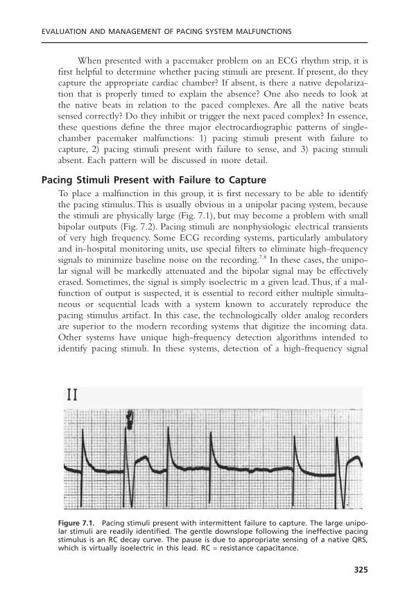
When presented with a pacemaker problem on an ECG rhythm strip, it isfirst helpful to determine whether pacing stimuli are present. If present, do theycapture the appropriate cardiac chamber? If absent, is there a native depolariza-tion that is properly timed to explain the absence? One also needs to look atthe native beats in relation to the paced complexes. Are all the native beatssensed correctly? Do they inhibit or trigger the next paced complex? In essence,these questions define the three major electrocardiographic patterns of single-chamber pacemaker malfunctions: 1) pacing stimuli present with failure tocapture, 2) pacing stimuli present with failure to sense, and 3) pacing stimuliabsent. Each pattern will be discussed in more detail.
Pacing Stimuli Present with Failure to CaptureTo place a malfunction in this group, it is first necessary to be able to identifythe pacing stimulus.This is usually obvious in a unipolar pacing system, becausethe stimuli are physically large (Fig. 7.1), but may become a problem with smallbipolar outputs (Fig. 7.2). Pacing stimuli are nonphysiologic electrical transientsof very high frequency. Some ECG recording systems, particularly ambulatoryand in-hospital monitoring units, use special filters to eliminate high-frequencysignals to minimize baseline noise on the recording.7,8 In these cases, the unipo-lar signal will be markedly attenuated and the bipolar signal may be effectivelyerased. Sometimes, the signal is simply isoelectric in a given lead.Thus, if a mal-function of output is suspected, it is essential to record either multiple simulta-neous or sequential leads with a system known to accurately reproduce thepacing stimulus artifact. In this case, the technologically older analog recordersare superior to the modern recording systems that digitize the incoming data.Other systems have unique high-frequency detection algorithms intended toidentify pacing stimuli. In these systems, detection of a high-frequency signal
EVALUATION AND MANAGEMENT OF PACING SYSTEM MALFUNCTIONS
325
Figure 7.1. Pacing stimuli present with intermittent failure to capture. The large unipo-lar stimuli are readily identified. The gentle downslope following the ineffective pacingstimulus is an RC decay curve. The pause is due to appropriate sensing of a native QRS,which is virtually isoelectric in this lead. RC = resistance capacitance.
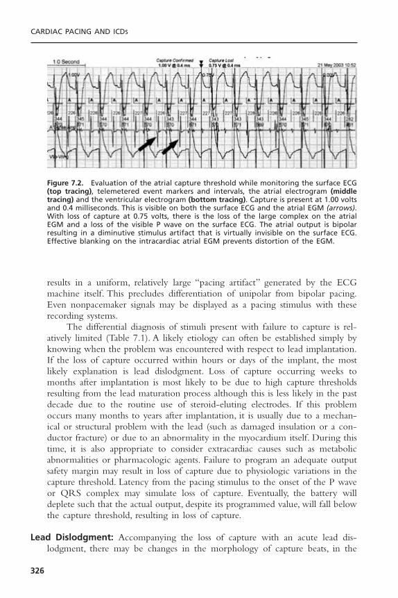
results in a uniform, relatively large “pacing artifact” generated by the ECGmachine itself. This precludes differentiation of unipolar from bipolar pacing.Even nonpacemaker signals may be displayed as a pacing stimulus with theserecording systems.
The differential diagnosis of stimuli present with failure to capture is rel-atively limited (Table 7.1). A likely etiology can often be established simply byknowing when the problem was encountered with respect to lead implantation.If the loss of capture occurred within hours or days of the implant, the mostlikely explanation is lead dislodgment. Loss of capture occurring weeks tomonths after implantation is most likely to be due to high capture thresholdsresulting from the lead maturation process although this is less likely in the pastdecade due to the routine use of steroid-eluting electrodes. If this problemoccurs many months to years after implantation, it is usually due to a mechan-ical or structural problem with the lead (such as damaged insulation or a con-ductor fracture) or due to an abnormality in the myocardium itself. During thistime, it is also appropriate to consider extracardiac causes such as metabolicabnormalities or pharmacologic agents. Failure to program an adequate outputsafety margin may result in loss of capture due to physiologic variations in thecapture threshold. Latency from the pacing stimulus to the onset of the P waveor QRS complex may simulate loss of capture. Eventually, the battery willdeplete such that the actual output, despite its programmed value, will fall belowthe capture threshold, resulting in loss of capture.
Lead Dislodgment: Accompanying the loss of capture with an acute lead dis-lodgment, there may be changes in the morphology of capture beats, in the
CARDIAC PACING AND ICDS
326
Figure 7.2. Evaluation of the atrial capture threshold while monitoring the surface ECG(top tracing), telemetered event markers and intervals, the atrial electrogram (middletracing) and the ventricular electrogram (bottom tracing). Capture is present at 1.00 voltsand 0.4 milliseconds. This is visible on both the surface ECG and the atrial EGM (arrows).With loss of capture at 0.75 volts, there is the loss of the large complex on the atrialEGM and a loss of the visible P wave on the surface ECG. The atrial output is bipolarresulting in a diminutive stimulus artifact that is virtually invisible on the surface ECG.Effective blanking on the intracardiac atrial EGM prevents distortion of the EGM.
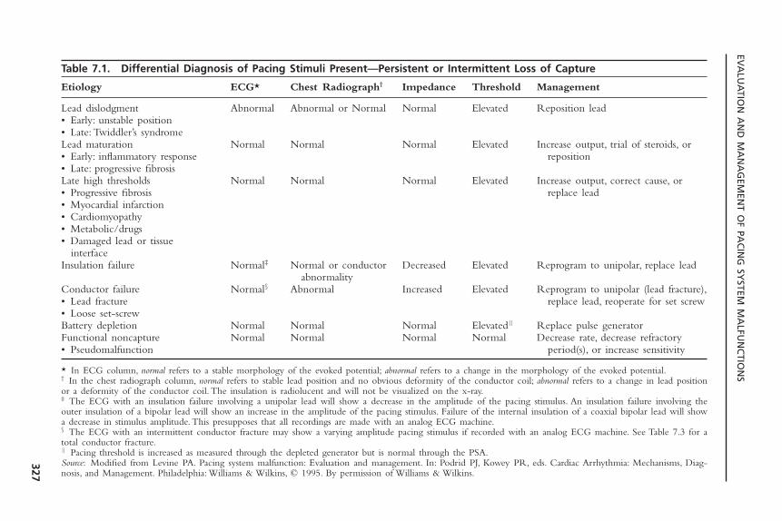
EVA
LUA
TION
AN
D M
AN
AG
EMEN
T OF PA
CIN
G SY
STEM M
ALFU
NC
TION
S
327
Table 7.1. Differential Diagnosis of Pacing Stimuli Present—Persistent or Intermittent Loss of Capture
Etiology ECG* Chest Radiograph† Impedance Threshold Management
Lead dislodgment Abnormal Abnormal or Normal Normal Elevated Reposition lead• Early: unstable position• Late: Twiddler’s syndromeLead maturation Normal Normal Normal Elevated Increase output, trial of steroids, or • Early: inflammatory response reposition• Late: progressive fibrosisLate high thresholds Normal Normal Normal Elevated Increase output, correct cause, or • Progressive fibrosis replace lead• Myocardial infarction• Cardiomyopathy• Metabolic/drugs• Damaged lead or tissue
interfaceInsulation failure Normal‡ Normal or conductor Decreased Elevated Reprogram to unipolar, replace lead
abnormalityConductor failure Normal§ Abnormal Increased Elevated Reprogram to unipolar (lead fracture),• Lead fracture replace lead, reoperate for set screw• Loose set-screwBattery depletion Normal Normal Normal Elevated|| Replace pulse generatorFunctional noncapture Normal Normal Normal Normal Decrease rate, decrease refractory• Pseudomalfunction period(s), or increase sensitivity
* In ECG column, normal refers to a stable morphology of the evoked potential; abnormal refers to a change in the morphology of the evoked potential.† In the chest radiograph column, normal refers to stable lead position and no obvious deformity of the conductor coil; abnormal refers to a change in lead positionor a deformity of the conductor coil. The insulation is radiolucent and will not be visualized on the x-ray.‡ The ECG with an insulation failure involving a unipolar lead will show a decrease in the amplitude of the pacing stimulus. An insulation failure involving theouter insulation of a bipolar lead will show an increase in the amplitude of the pacing stimulus. Failure of the internal insulation of a coaxial bipolar lead will showa decrease in stimulus amplitude. This presupposes that all recordings are made with an analog ECG machine.§ The ECG with an intermittent conductor fracture may show a varying amplitude pacing stimulus if recorded with an analog ECG machine. See Table 7.3 for atotal conductor fracture.|| Pacing threshold is increased as measured through the depleted generator but is normal through the PSA.Source: Modified from Levine PA. Pacing system malfunction: Evaluation and management. In: Podrid PJ, Kowey PR, eds. Cardiac Arrhythmia: Mechanisms, Diag-nosis, and Management. Philadelphia: Williams & Wilkins, © 1995. By permission of Williams & Wilkins.

dipole of the pacing stimulus, and/or in the lead position identified on a repeatchest radiograph. It is important to obtain the follow-up chest radiograph in anidentical projection to that used for the baseline study. Even so, small “micro-dislodgments” of the lead tip may compromise the electrode contact with themyocardium but not be discernible with radiography. Despite some early reportsin the literature to the contrary, neither partial lead dislodgment nor a simplerise in capture threshold due to tissue reaction at the electrode-myocardial inter-face will result in a significant change in stimulation impedance.4
A change in the morphology of the capture beat is often a clue to leaddislodgment, but this is the case only when fusion with the native QRS complexis absent. Fusion can also occur in the atrium.The morphologic changes in thepaced P wave when combined with the native atrial depolarization are moredifficult to identify because of the smaller size of the atrial complex. In biven-tricular systems, one has to be concerned with the position of two ventricularleads—one in the right ventricle and the other stimulating the left ventricle.
Correction of a lead dislodgment requires surgical intervention to reposi-tion the lead. Before this is done, the reason for the dislodgment should beinvestigated. Careful attention should be directed to the original chest radio-graph, and an adequate heel on the intracardiac portion of the lead should besought at the time of lead implantation. Either too little or too much will pre-dispose to dislodgment.9 One should also review the recorded electrograms fromthe initial implant, looking for a 2 to 3mV current of injury pattern (“ST-segment” elevation). The absence of this degree of current of injury has beencorrelated with an increased incidence of lead dislodgment; the implication isthat the electrode is not making good endocardial contact. An examination ofthe anchoring sleeve for adequate fixation should be done at the time of reoperation.10
One should observe several precautions at the time of lead repositioning.When repositioning a dislodged lead, a thrombus may have developed aroundthe lead tip, encasing the passive-fixation tines or fins or active-fixation helix,effectively preventing the lead from being adequately secured at the repeat pro-cedure.Thus, once the lead is thought to be in a good position, the patient shouldbe instructed to take as deep a breath as possible and to cough vigorously so thatthe electrical and mechanical stability of the lead may be assessed. If the dis-lodgment is due to Twiddler’s syndrome, the most common cause of a late leaddislodgment, the portion of the lead within the pocket should be carefullyinspected. If damage to the conductor coil or insulation is noted, the lead shouldnot be reused. If a dislodgment occurs and the reason is not sufficiently appar-ent that it could be corrected at the second procedure, it would be prudent toremove the dislodged lead and replace it with an active fixation lead. One needsto be aware that use of an active fixation lead does not guarantee chronic stability—dislodgments have been reported years after implantation.9,11
High Thresholds; Lead Maturation: When the electrode is first inserted, it ismaking intimate contact with the endocardium. The presence of foreign mate-
CARDIAC PACING AND ICDS
328

rial and the pressure of the lead-electrode system against the myocardium inducean inflammatory reaction at the electrode-myocardial interface.This local traumais responsible for the current of injury pattern on the acute EGM recording.Due to the inflammatory reaction, the electrode is physically displaced from theexcitable myocardium. This process increases the capture threshold. In addition,it attenuates the electrogram amplitude and slew rate to compromise sensing.With time, the inflammatory reaction subsides, leaving a thin capsule of fibroustissue between the electrode and active myocardium. As the distance betweenthe electrode and active myocardium is reduced, the capture and sensing thresh-olds improve.
Sometimes the inflammatory reaction at the electrode–myocardial interfaceis excessive, causing the capture threshold to rise above the output of the pace-maker.11–14 This has been termed exit block. If exit block is the reason for lossof capture, there will be no change in the morphology of any capture beats,nor will there be a change in the radiographic position of the lead. Exit blockcan occur even with steroid-eluting leads and excellent acute capture thresh-olds; however, if the implanting physician accepts an electrode position with ahigh threshold (i.e., greater than 1.5V), there may be an increased likelihood ofexit block due to less “reserve” for the threshold to rise. The literature reportsthe incidence of exit block of less than 5%.11
Early experience with systemic steroids to limit acute threshold rises ledto the development of the steroid-eluting electrode, which has been effective inattenuating the inflammatory reaction and its associated early rise in capture andsensing thresholds.15–20 Isolated cases of massive threshold rises have also beenencountered with the steroid-eluting leads, although the incidence is probablylower than with non–steroid-eluting leads.21,22 Acute management of highthresholds, with or without loss of capture, requires increasing the output of thepacemaker. If this is not feasible, one needs to determine the status of the nativeunderlying rhythm. If it is stable and adequate to physiologically support thepatient, one might simply wait for the threshold to fall or try a course of highdose systemic steroids. If the underlying rhythm is not stable, one will need toinsert a temporary pacemaker lead and consider an urgent intervention to reposition or replace the lead.
If thresholds increase during the early postimplantation period and oneelects to use systemic steroids in an attempt to reverse the phenomenon, aregimen of 60mg of prednisone per day, often administered in divided doses,has been found effective in approximately 50% of patients. In the pediatric pop-ulation, the dose is 1mg/kg. Capture thresholds are repeated 4 to 5 days afterthe initiation of steroids. If there is no change or if there is a further increasein capture thresholds, the steroids are considered ineffective and are simply dis-continued. If the threshold, however, has decreased by at least two programmingsteps (pulse width and/or pulse amplitude), it is likely that the steroids are effec-tive.The steroids are then continued for a month, with biweekly monitoring ofcapture thresholds. At the end of the month, a slow but progressive taperingschedule is initiated that continues for a minimum of 2 months.
EVALUATION AND MANAGEMENT OF PACING SYSTEM MALFUNCTIONS
329

High Thresholds; Chronic Lead: High capture thresholds may develop at anytime. Those that are not associated with the acute lead maturation process arenot likely to respond to steroids.When this problem is encountered, one shouldevaluate the patient for transient etiologies, including electrolyte and acid-baseabnormalities such as hyperkalemia and acidemia.15–17,23–26 Also included arepharmacologic agents such as the antiarrhythmic drugs; the 1C agents such asflecainide have developed a particularly poor reputation.27–30 If a transient causeis identified and it can be corrected, the problem can be managed with a tran-sient increase in output or by use of temporary pacing until the situation hasresolved.
Permanent late rises in capture thresholds may also occur with progressivemyocardial fibrosis, a primary myopathic process, or myocardial infarction.31 Ifthe output programmability of the device is not sufficient to overcome thesecauses, placement of a new lead will be required. Given that the lead is notinfected, explantation is not mandatory.32
One must be very cautious about invoking the diagnosis of a high thresh-old due to a primary myocardial process in the absence of a change in the mor-phology of the intrinsic P wave or QRS complex.With a stable native complexon the surface ECG, a more likely explanation is a primary problem develop-ing with the lead itself. If the malfunction were due to a mechanical abnor-mality developing in the lead, one would expect to see a change in thetelemetered or invasively measured stimulation impedance, although this maynot always be the case. Normal telemetry values may occur in the presence ofan intermittent problem if the lead was functioning properly at the time of themeasurements. When the lead impedance is abnormal, a very low impedancevalue (commonly less than 200 ohms) reflects a failure of the insulation, mostcommonly the inner insulation in a coaxial bipolar lead. A very high lead impedance (greater than 2000 to 3000 ohms) is consistent with a complete conductor fracture (open circuit). Measurement-to-measurement changes intelemetered lead impedance that are still within the normal range are totallyconsistent with normal lead function. Changes up to 300 ohms may still becompatible with normal lead function.33 Further, a change in the measuredimpedance in the absence of a clinical malfunction, such as a massive rise incapture threshold, noncapture, or a sensing problem, may be a telemetry error.Although this might warrant closer follow-up assessment, an isolated abnor-mality of a telemetry measurement does not mandate operative intervention.
Lead Insulation Defects: An insulation defect may develop from the intrinsicdesign and/or a manufacturing limitation as was the case with an early seriesof 80A polyurethane insulated leads. Most insulation problems, however, are dueto extrinsic forces applied to the lead either at or following implant that phys-ically damage the lead. In part, this problem is a direct result of the request bythe medical community for thinner leads, both unipolar and bipolar. Onemethod of reducing the lead’s diameter is to reduce the thickness of the insu-lating material. In-line bipolar coaxial leads are the least forgiving of extrinsic
CARDIAC PACING AND ICDS
330
stresses for this very reason. Insulation defects have occurred with both siliconerubber and polyurethane insulation material.34 Industry continues to evaluatenew materials having the relative benefits of both polyurethane and siliconerubber while minimizing some of their weaknesses.
Extrinsic stress applied to the lead can result in damage to the insulationand/or a conductor fracture. There are three common mechanical stresses onthe lead. The first is the suture sleeve, in which an excessively tight ligature isused to anchor the lead to the underlying fascia. If one sees a visible distortionof the conductor coil either at implant or on a follow-up chest radiograph, theligature around the suture sleeve and lead is too tight.35 Although this was orig-inally considered a benign observation, late adverse consequences associated withthis area of stress have recently been appreciated.34 The second source of stresson the lead is the point where the lead traverses the plane between the clavi-cle and first rib on its way to the subclavian vein.36,37 The normal motion ofthe arm causes the space between the clavicle and first rib to widen and narrow,much like the jaws of pliers. This is exacerbated if the course of the lead tra-verses the costoclavicular ligament or the subclavius muscle in its path to thesubclavian vein. The lead located in this position can be repeatedly crushed,pinched, pulled or stretched, resulting in a deformation of the conductor coils,which in turn will predispose to either an insulation failure and/or conductorfracture occurring months to years after implantation (Fig. 7.3). This has beentermed the medial subclavicular musculotendinous complex and is an increasingly rec-ognized cause of malfunction of both standard pacing and defibrillator leads. Arecent recommendation has been to access the axillary or cephalic vein ratherthan the subclavian vein to avoid both the acute and late complications associ-ated with the implant procedure.38,39
A third mechanism involves abrasion of the external insulation. This mayoccur between overlapping coils of the same or contiguous leads or betweenthe housing of the pulse generator and the lead coiled behind it.
Manifestations of a lead insulation defect are determined, in part, by thelocation of the defect.40 In unipolar leads or a defect associated with the prox-imal conductor of a bipolar lead, there may be extracardiac muscle stimulationdue to the electrical current leaking from the defect. Muscle stimulation in thearea of a unipolar pacemaker may also be due to an upside-down pacemakerwith the anode or indifferent electrode making direct contact with the under-lying muscle. The author is also aware of several cases in which the insulatingmaterial applied to the pulse generator was damaged, thus allowing for localmuscle stimulation with a totally normal lead.
Another manifestation of a lead insulation defect includes changes in theamplitude of the pacing stimulus, although this is difficult to evaluate given the differences in pacemaker stimulus reproduction between different ECGmachines. This is best identified with an analog ECG recording system. In aunipolar system, there is a shorter path between the exposed conductor and thepulse generator, resulting in attenuation of the pacemaker stimulus amplitude.When the breach involves the outer insulation covering the anodal conductor
EVALUATION AND MANAGEMENT OF PACING SYSTEM MALFUNCTIONS
331
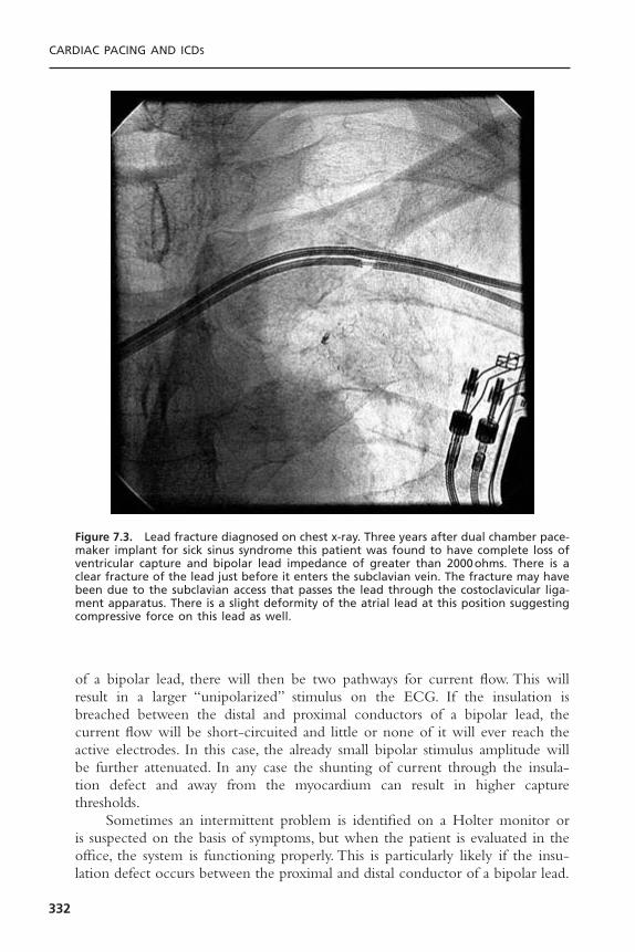
of a bipolar lead, there will then be two pathways for current flow. This willresult in a larger “unipolarized” stimulus on the ECG. If the insulation isbreached between the distal and proximal conductors of a bipolar lead, thecurrent flow will be short-circuited and little or none of it will ever reach theactive electrodes. In this case, the already small bipolar stimulus amplitude willbe further attenuated. In any case the shunting of current through the insula-tion defect and away from the myocardium can result in higher capture thresholds.
Sometimes an intermittent problem is identified on a Holter monitor oris suspected on the basis of symptoms, but when the patient is evaluated in theoffice, the system is functioning properly. This is particularly likely if the insu-lation defect occurs between the proximal and distal conductor of a bipolar lead.
CARDIAC PACING AND ICDS
332
Figure 7.3. Lead fracture diagnosed on chest x-ray. Three years after dual chamber pace-maker implant for sick sinus syndrome this patient was found to have complete loss ofventricular capture and bipolar lead impedance of greater than 2000ohms. There is aclear fracture of the lead just before it enters the subclavian vein. The fracture may havebeen due to the subclavian access that passes the lead through the costoclavicular liga-ment apparatus. There is a slight deformity of the atrial lead at this position suggestingcompressive force on this lead as well.
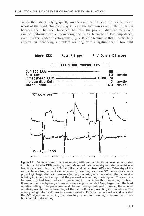
When the patient is lying quietly on the examination table, the normal elasticrecoil of the conductor coils may separate the two wires even if the insulationbetween them has been breached. To reveal the problem different maneuverscan be performed while monitoring the ECG, telemetered lead impedance,event markers, and/or electrograms (Fig. 7.4). One technique that is particularlyeffective in identifying a problem resulting from a ligature that is too tight
EVALUATION AND MANAGEMENT OF PACING SYSTEM MALFUNCTIONS
333
Figure 7.4. Repeated ventricular oversensing with resultant inhibition was demonstratedin this dual bipolar DDD pacing system. Measured data telemetry reported a ventricularlead impedance of less than 250ohms; the baseline had been 645ohms. Telemetry of theventricular electrogram while simultaneously recording a surface ECG demonstrates non-physiologic large electrical transients (arrows) occurring at a time when the pacemakeris being inhibited, indicating that the pacemaker is sensing these signals. The ventricu-lar sensitivity had been reduced in an attempt to minimize this oversensing problem.However, the nonphysiologic transients were approximately 20mV, larger than the leastsensitive setting of the pacemaker, and the oversensing continued. However, the reducedsensitivity resulted in undersensing of the native R waves, resulting in competition. Thenonphysiologic electrical transients were treated as PVCs by the pacemaker and activatedthe PVC algorithm, extending the refractory period and resulting in intermittent func-tional atrial undersensing.
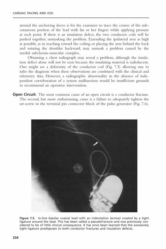
around the anchoring sleeve is for the examiner to trace the course of the sub-cutaneous portion of the lead with his or her fingers while applying pressureat each point. If there is an insulation defect, the two conductor coils will bepushed together, unmasking the problem. Extending the ipsilateral arm as highas possible, as in reaching toward the ceiling or placing the arm behind the backand rotating the shoulder backward, may unmask a problem caused by themedial subclavian-muscular complex.
Obtaining a chest radiograph may reveal a problem, although the insula-tion defect alone will not be seen because the insulating material is radiolucent.One might see a deformity of the conductor coil (Fig. 7.5) allowing one toinfer the diagnosis when these observations are combined with the clinical andtelemetry data. However, a radiographic abnormality in the absence of inde-pendent corroboration of a system malfunction would be insufficient groundsto recommend an operative intervention.
Open Circuit: The most common cause of an open circuit is a conductor fracture.The second, but more embarrassing, cause is a failure to adequately tighten theset-screw in the terminal pin connector block of the pulse generator (Fig. 7.6).
CARDIAC PACING AND ICDS
334
Figure 7.5. In-line bipolar coaxial lead with an indentation (arrow) created by a tightligature around the lead. This has been called a pseudofracture and was previously con-sidered to be of little clinical consequence. It has since been learned that the excessivelytight ligature predisposes to both conductor fractures and insulation defects.

There are two common clinical manifestations of an open circuit. With a totalopen circuit, no energy will traverse the gap between the two portions of thelead and there will be an absence of pacing artifacts on the ECG and loss ofcapture. This is included in the class of malfunction associated with an absentpacing stimulus. If the two ends of the conductor are making any contact at all,the resistance to current flow will be increased to attenuate the amount ofcurrent and energy reaching the heart, but a stimulus will be present. If theeffective energy reaching the heart is subthreshold, there will be loss of capture.Although a physical break in the conductor is the most common cause of anopen circuit and usually does not manifest until months to years after implan-tation, there are two circumstances when an open circuit can occur at the time
EVALUATION AND MANAGEMENT OF PACING SYSTEM MALFUNCTIONS
335
Figure 7.6. Chest radiograph demonstrating displacement of the terminal pin out of thehead of a pacemaker. For the atrial lead entering the top of the header (bottom of thefigure) the terminal pin is seen extending beyond the header posts for both the ring andtip electrodes (heavy arrow). The ventricular lead, however, does not reach to the headerpost for the tip electrode (thin arrow). The ventricular lead impedance was unmeasur-able. In addition, pseudofractures are seen in both leads due to constriction of the insu-lation by the tying sleeves (arrowheads).
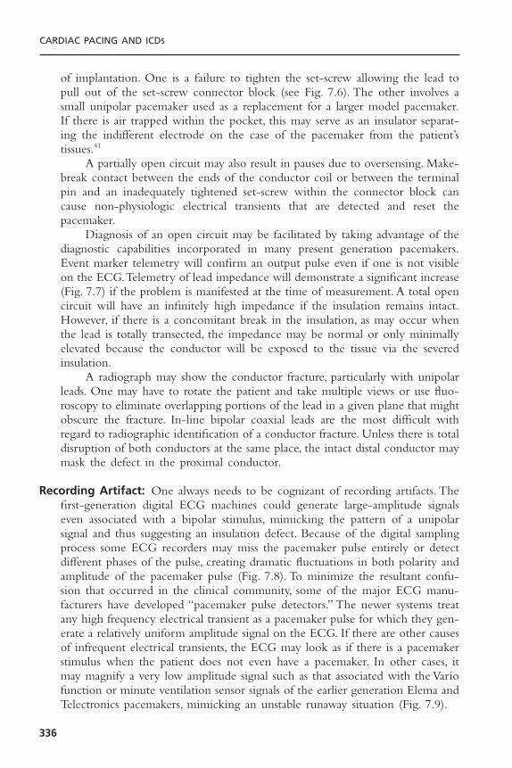
of implantation. One is a failure to tighten the set-screw allowing the lead topull out of the set-screw connector block (see Fig. 7.6). The other involves asmall unipolar pacemaker used as a replacement for a larger model pacemaker.If there is air trapped within the pocket, this may serve as an insulator separat-ing the indifferent electrode on the case of the pacemaker from the patient’stissues.41
A partially open circuit may also result in pauses due to oversensing. Make-break contact between the ends of the conductor coil or between the terminalpin and an inadequately tightened set-screw within the connector block cancause non-physiologic electrical transients that are detected and reset the pacemaker.
Diagnosis of an open circuit may be facilitated by taking advantage of thediagnostic capabilities incorporated in many present generation pacemakers.Event marker telemetry will confirm an output pulse even if one is not visibleon the ECG.Telemetry of lead impedance will demonstrate a significant increase(Fig. 7.7) if the problem is manifested at the time of measurement. A total opencircuit will have an infinitely high impedance if the insulation remains intact.However, if there is a concomitant break in the insulation, as may occur whenthe lead is totally transected, the impedance may be normal or only minimallyelevated because the conductor will be exposed to the tissue via the severedinsulation.
A radiograph may show the conductor fracture, particularly with unipolarleads. One may have to rotate the patient and take multiple views or use fluo-roscopy to eliminate overlapping portions of the lead in a given plane that mightobscure the fracture. In-line bipolar coaxial leads are the most difficult withregard to radiographic identification of a conductor fracture. Unless there is totaldisruption of both conductors at the same place, the intact distal conductor maymask the defect in the proximal conductor.
Recording Artifact: One always needs to be cognizant of recording artifacts. Thefirst-generation digital ECG machines could generate large-amplitude signalseven associated with a bipolar stimulus, mimicking the pattern of a unipolarsignal and thus suggesting an insulation defect. Because of the digital samplingprocess some ECG recorders may miss the pacemaker pulse entirely or detectdifferent phases of the pulse, creating dramatic fluctuations in both polarity andamplitude of the pacemaker pulse (Fig. 7.8). To minimize the resultant confu-sion that occurred in the clinical community, some of the major ECG manu-facturers have developed “pacemaker pulse detectors.” The newer systems treatany high frequency electrical transient as a pacemaker pulse for which they gen-erate a relatively uniform amplitude signal on the ECG. If there are other causesof infrequent electrical transients, the ECG may look as if there is a pacemakerstimulus when the patient does not even have a pacemaker. In other cases, itmay magnify a very low amplitude signal such as that associated with the Variofunction or minute ventilation sensor signals of the earlier generation Elema andTelectronics pacemakers, mimicking an unstable runaway situation (Fig. 7.9).
CARDIAC PACING AND ICDS
336

EVALUATION AND MANAGEMENT OF PACING SYSTEM MALFUNCTIONS
337
Figure 7.7. A: This tracing, recorded from a patient with a St. Jude Medical Integritypacemaker programmed to the DDD mode shows atrial pacing (“A” on marker channel)with intact AV nodal conduction. A ventricular stimulus is not visible on surface ECG. Ifit weren’t for the simultaneously telemetered event markers, one would not know thatthe pulse generator was releasing a ventricular output pulse (“V” on marker channel).The failure to deliver an effective stimulus to the ventricular channel was due to an opencircuit on the ventricular channel with a measured lead impedance of greater than 2500ohms. B: Measured data telemetry indicates that there is an open circuit on the atrialchannel of a different patient, implanted with a Medtronic Kappa 700 pacing system.The reported impedance is greater than 9999ohms, which is the highest impedance thatthe Medtronic system will report. The pulse current and pulse energy are minimal, whichis compatible with an open circuit.
A
B
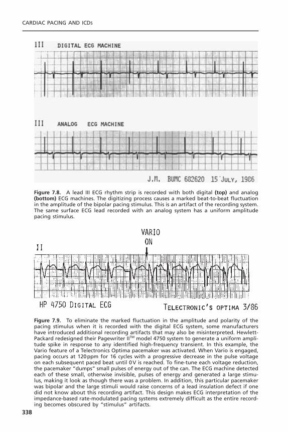
CARDIAC PACING AND ICDS
338
Figure 7.8. A lead III ECG rhythm strip is recorded with both digital (top) and analog(bottom) ECG machines. The digitizing process causes a marked beat-to-beat fluctuationin the amplitude of the bipolar pacing stimulus. This is an artifact of the recording system.The same surface ECG lead recorded with an analog system has a uniform amplitudepacing stimulus.
Figure 7.9. To eliminate the marked fluctuation in the amplitude and polarity of thepacing stimulus when it is recorded with the digital ECG system, some manufacturershave introduced additional recording artifacts that may also be misinterpreted. Hewlett-Packard redesigned their Pagewriter IITM model 4750 system to generate a uniform ampli-tude spike in response to any identified high-frequency transient. In this example, theVario feature of a Telectronics Optima pacemaker was activated. When Vario is engaged,pacing occurs at 120ppm for 16 cycles with a progressive decrease in the pulse voltageon each subsequent paced beat until 0V is reached. To fine-tune each voltage reduction,the pacemaker “dumps” small pulses of energy out of the can. The ECG machine detectedeach of these small, otherwise invisible, pulses of energy and generated a large stimu-lus, making it look as though there was a problem. In addition, this particular pacemakerwas bipolar and the large stimuli would raise concerns of a lead insulation defect if onedid not know about this recording artifact. This design makes ECG interpretation of theimpedance-based rate-modulated pacing systems extremely difficult as the entire record-ing becomes obscured by “stimulus” artifacts.
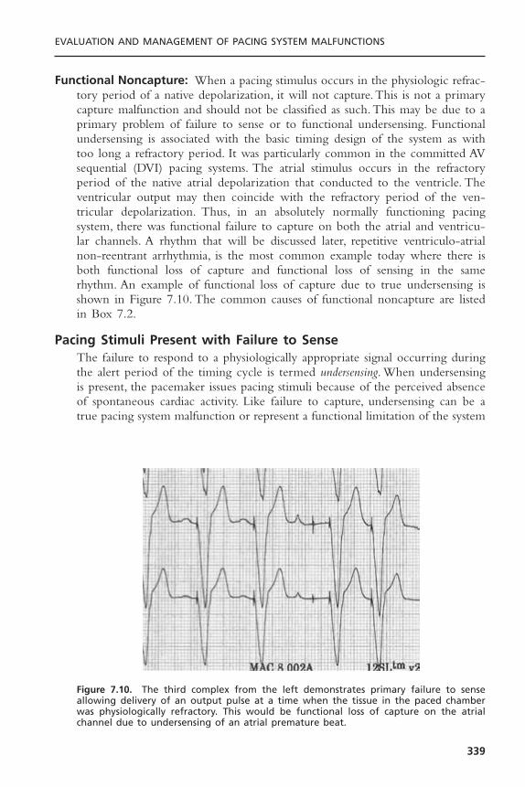
Functional Noncapture: When a pacing stimulus occurs in the physiologic refrac-tory period of a native depolarization, it will not capture.This is not a primarycapture malfunction and should not be classified as such. This may be due to aprimary problem of failure to sense or to functional undersensing. Functionalundersensing is associated with the basic timing design of the system as withtoo long a refractory period. It was particularly common in the committed AVsequential (DVI) pacing systems. The atrial stimulus occurs in the refractoryperiod of the native atrial depolarization that conducted to the ventricle. Theventricular output may then coincide with the refractory period of the ven-tricular depolarization. Thus, in an absolutely normally functioning pacingsystem, there was functional failure to capture on both the atrial and ventricu-lar channels. A rhythm that will be discussed later, repetitive ventriculo-atrialnon-reentrant arrhythmia, is the most common example today where there isboth functional loss of capture and functional loss of sensing in the same rhythm. An example of functional loss of capture due to true undersensing isshown in Figure 7.10. The common causes of functional noncapture are listedin Box 7.2.
Pacing Stimuli Present with Failure to SenseThe failure to respond to a physiologically appropriate signal occurring duringthe alert period of the timing cycle is termed undersensing. When undersensingis present, the pacemaker issues pacing stimuli because of the perceived absenceof spontaneous cardiac activity. Like failure to capture, undersensing can be atrue pacing system malfunction or represent a functional limitation of the system
EVALUATION AND MANAGEMENT OF PACING SYSTEM MALFUNCTIONS
339
Figure 7.10. The third complex from the left demonstrates primary failure to senseallowing delivery of an output pulse at a time when the tissue in the paced chamberwas physiologically refractory. This would be functional loss of capture on the atrialchannel due to undersensing of an atrial premature beat.
due to the unique algorithms or programmed settings (Fig. 7.11).The differen-tial diagnosis of undersensing along with the diagnostic tests and managementoptions are detailed in Table 7.2. One cause of undersensing is that of inade-quate signal amplitude at the time of initial implant.This may result if the patienthas no intrinsic rhythm to measure at implant (i.e., temporary ventricular pacingor, on the atrial channel, atrial fibrillation). At implant, device based testing isbest but few of the available pacing system analyzers (PSA) use the sensing cir-cuitry of the implanted pacemaker.The filtering characteristics of the PSA maydiffer significantly from those of the pulse generator and may provide mislead-ing information at implant (Fig. 7.12).42
Change in Native Signal: Another etiology of undersensing is that the signal haschanged.43 The change in the signal may be permanent, as with a myocardialinfarction or a primary myopathic process. It also may result from a change inthe sequence of depolarization, as with development of a bundle branch block.Hyperkalemia results in a widening of the QRS complex and an attenuationof the P wave on the surface ECG. Similar changes will occur with the intrac-ardiac signal or electrogram. Pharmacologic therapy, particularly the antiar-rhythmic agents that alter Phase 0 of the cardiac action potential, can changethe intrinsic properties of the signal, resulting in undersensing. If possible, theseagents should be discontinued before considering an operative intervention toreplace or reposition the lead if the primary indication for the procedure isundersensing. One should also check the patient’s serum electrolytes and arte-rial blood gases and correct any identified abnormalities before consideringinterventions other than programming to a more sensitive setting.
CARDIAC PACING AND ICDS
340
Box 7.2. Common Causes of Functional Noncapture
Single chamberTrue undersensingLong refractory periodEctopic activation (PVC, bundle branch block)Asynchronous pacing (magnet application, noise reversion)
Dual chamberAtrial undersensingAtrial asynchronous modes (DDI, DVI)
Blanking periodSafety pacingPVARP extension algorithms post-PVCLong PVARP and high base rateMode switching
PVARP = postventricular atrial refractory period; PVC = premature ventricular contraction.

Inappropriate Programmed Sensitivity: An embarrassing cause of undersensingis an inappropriately programmed sensitivity. Confusion about the terms highand low sensitivity may result in incorrect programming.When an undersensingproblem is encountered, the sensitivity should be increased or set to a higher sen-sitivity so that the system will recognize and respond to smaller amplitudesignals. Sensitivity is the amplitude of the signal that can be sensed. A sensitiv-ity of 1 mV would be more sensitive (higher sensitivity) than 2mV. Similarly, ifthere is an oversensing problem and one wants to reduce or lower the sensi-tivity, the incoming signal must be larger than the amplitude chosen for thepacemaker to recognize it as an appropriate signal. Thus, a sensitivity of 4mV,although a higher number, is really a lower sensitivity than 2mV. Patients havebeen inappropriately referred for pulse generator replacement or lead reposi-tioning when the problem was undersensing, which had resulted from a mis-understanding of how to program sensitivity.
Many of the newer pacemakers have incorporated an automatic sensingalgorithm.44 This algorithm monitors the amplitude of the native atrial or ven-tricular depolarization and either recommends a programmed sensitivity or auto-matically adjusts the sensitivity to maintain a 2 :1 safety margin. The limitationof these automatic algorithms is an inability to respond to isolated prematurebeats. This may result in the failure to detect isolated ectopic beats resulting incompetition or delaying the prompt recognition of a supraventricular or ven-tricular tachycardia.
Lead Insulation Failure: Lead insulation defects were discussed in the previoussection on stimuli present with loss of capture.The breach in the insulation willattenuate the incoming signal. The signal will be an electrical average betweenthe true electrode inside the heart and the false “electrode”—the exposed
EVALUATION AND MANAGEMENT OF PACING SYSTEM MALFUNCTIONS
341
Figure 7.11. A telemetry rhythm strip from a patient with a St. Jude Medical AffinityDR pulse generator with AutoCapture enabled. There is intermittent AV block. Whenconduction is intact, the low amplitude ventricular output pulse coincides with the nativeQRS complex resulting in a fusion beat. The resultant evoked response is not detectedcausing the release of a 4.5-V backup pulse to be delivered in the ST segment. This isshown in complexes 8 and 10 and flagged as “non-sensing” by the clinical staff. This isnormal function although it might be labeled functional undersensing.

342
Table 7.2. Differential Diagnosis of Pacing Stimuli Present—Intermittent orPersistent Failure to Sense
Etiology Diagnostic Evaluation* Management*
Lead dislodgment 12-lead ECG with pacing; Reposition lead• Early: unstable position chest radiograph• Late: Twiddler’s syndrome
Low amplitude electrogram Identification of change Increase sensitivity,• Small EGM at implant in medication, discontinue medication,• Ectopic activation (PAC, electrolytes, cardiac correct electrolyte or
PVC, bundle branch block, status acid–base imbalance,atrial fibrillation) change sensing
• Medications, electrolytes configuration• Myocardial infarction,
cardiomyopathy• Tissue fibrosis, lead
maturation
Insulation failure Fall in lead impedance by Change sensing more than 300ohms; configuration until lead telemetered EGM can be replaced
Functional undersensing Careful assessment of Decrease refractory • Magnet application, noise pacing intervals, review period(s), increase
reversion programmed sensitivity sensitivity• ERI behavior and thresholds• PMT interventions• Mode switching• Pacemaker Wenckebach
Inappropriate programming Review programmed Reprogram sensitivitysensitivity and thresholds
* Some suggested options may not be available with a given pulse generator. Only definitive manage-ment options are listed. In each case, increasing the sensitivity may correct the problem, but, as with aprimary lead failure, this may be a temporizing measure only.Source: Modified from Levine PA. Pacing system malfunction: evaluation and management. In: PodridPJ, Kowey PR, eds. Cardiac Arrhythmia: Mechanisms, Diagnosis, and Management. Philadelphia:Williams& Wilkins, © 1995. By permission of Williams & Wilkins.
Figure 7.12. To demonstrate the difference between a filtered and unfiltered signal,both of which can be transmitted by telemetry, the standard bipolar ventricular electro-gram (VEGM) was recorded when the pacemaker was inhibited. A: This is the bipolarVEGM recorded between the tip and ring electrodes. The signal was acquired by thetelemetry circuit and transmitted before it was processed by the sensing circuit. The Rmarker aligns with the intrinsic deflection of the EGM. The visible repolarization artifactrepresenting the T wave demonstrates that the standard telemetry system uses a verybroad band-pass filter that does not significantly alter the signal. B: The same EGMtelemetered after it has been processed by the sensing circuit. This is termed the SenseAmp EGM. Note that the repolarization artifact is virtually eliminated and the signal mor-phology is markedly altered. The physical amplitude of this signal, as displayed by theprogrammer, will be directly dependent upon the programmed sensitivity or gain withinthe pacemaker. (Reprinted by permission from Levine PA. Guidelines to the Routine Eval-uation, Programming and Follow-up of the Patient with an Implanted Dual-ChamberRate-Modulated Pacing System. Sylmar, CA, St. Jude Medical CRMD, 2003.)
�
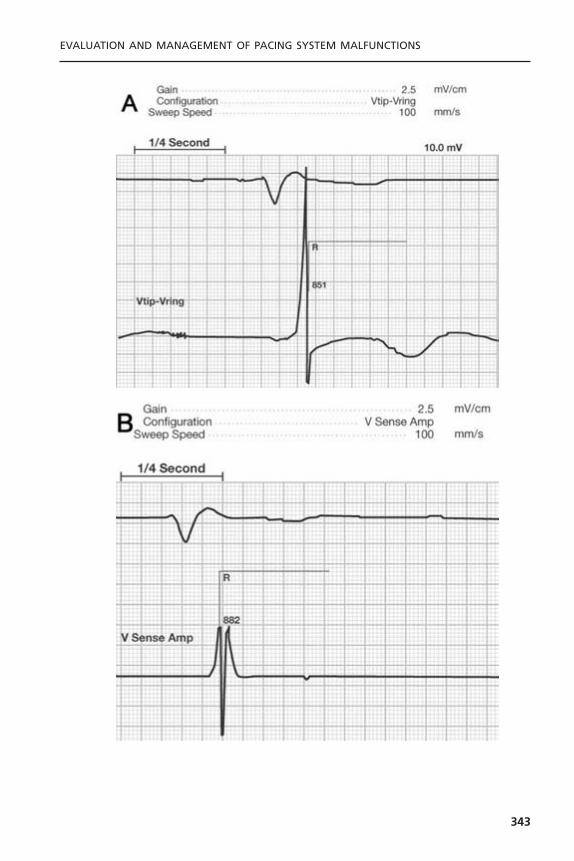
EVALUATION AND MANAGEMENT OF PACING SYSTEM MALFUNCTIONS
343
conductor coil under the insulation defect. If the pacemaker has the ability totelemeter the EGM and there is a baseline recording available, one can comparethe two signals. Other suggestive findings include a decrease in stimulationimpedance, increase in battery current drain, increase in capture threshold,change in pulse artifact amplitude if recorded with an analog system, and pos-sible extracardiac muscle stimulation. These findings are all corroboratory, sup-porting the likely cause of the sensing failure being a break in the insulation.One can temporize by increasing the sensitivity of the system, but definitivecorrection will require repair or replacement of the lead.
Lead Dislodgment: Although lead dislodgment usually results in loss of capture,it is also frequently accompanied by undersensing.The electrode may no longerbe in contact with the myocardium, or it may have been totally displaced fromthe appropriate cardiac chamber. In any case, the incoming signal will be dif-ferent from and usually smaller than that recorded at implant, resulting in sensingfailure. Correction requires repositioning the dislodged lead; however, increas-ing the sensitivity may restore normal sensing function until the lead can berepositioned.
Electrodes are being introduced to minimize far field sensing. This isaccomplished by using a very short interelectrode spacing. While this improvesthe signal to noise ratio and minimizes oversensing, minor shifts in the orien-tation of the bipolar dipole between the two closely spaced electrodes may dra-matically alter the signal that is being detected.
Lead Maturation: The inflammatory reaction that occurs at the electrode-myocardial interface physically separates the electrode from active functionalmyocardium. This will attenuate the amplitude of the signal. The signal has been reported to decrease by as much as 20% to 40% when compared to theelectrogram amplitude recorded at implantation. It also attenuates the slew rate, which may be the major reason for sensing failure. Treatment requiresincreasing the sensitivity of the pacemaker while initiating the other sug-gestions provided earlier for high capture thresholds associated with lead maturation.
Component Malfunction: Problems may occur with the sense amplifier of thepacemaker, resulting in an undersensing problem.There is no good way to assessthis noninvasively. Problems with the sense amplifier can certainly be suspectedif the telemetered EGM is of large amplitude and good slew rate, given the factthat the telemetry and sensing amplifier of many units are different. Similarobservations can be made at the time of operative intervention. If the recordedEGM is large with a good slew rate (>1V/sec) and the PSA-reported signalamplitude is large, one should suspect that the cause of the problem was intrin-sic to the pulse generator. In the differential diagnosis of this problem, this isthe least common cause of undersensing.
CARDIAC PACING AND ICDS
344

Functional Undersensing: Functional undersensing is a failure to sense an appro-priate physiologic signal but the undersensing is caused by the normal designof the pacemaker (Box 7.3).With respect to single-chamber pacing systems, thismost commonly occurs due to native beats falling within the refractory periodafter a paced or sensed beat, particularly common observation with ventricularpacing in the setting of atrial fibrillation and a rapid ventricular response. Fusionand pseudofusion beats are normal phenomenon. Given that many individualsreport these as a “sensing failure,” this is another example of functional under-sensing. The most common cause of functional undersensing occurs each timea magnet is placed over the pacemaker and induces asynchronous pacing.
If too many signals are sensed by the pacemaker in a very short time, thelikelihood is that this is electrical noise rather than true physiologic signals.Thisis termed electromagnetic interference (EMI) or “noise.” The presence of EMI pre-cludes the pacemaker’s differentiating electrical noise from an intrinsic rhythm.Rather than inhibiting the pacemaker when the patient might be asystolic, thepacemaker reverts to asynchronous function, termed noise mode operation.45
Pacing Stimuli Absent with Failure to CaptureThe next major category of pacing system malfunction occurs when the outputstimulus is truly absent (Fig. 7.13). One must be certain that this is not an arti-fact of a diminutive bipolar pacing stimulus further obscured by being isoelec-tric in a given lead (Fig. 7.14). Hence, one should record multiple leadssimultaneously or sequentially. Indeed, this might be the one indication for usinga digital ECG machine that re-creates a uniform amplitude stimulus in responseto any high-frequency transient. The differential diagnosis of pacing stimuliabsent is summarized in Table 7.3.
EVALUATION AND MANAGEMENT OF PACING SYSTEM MALFUNCTIONS
345
Box 7.3. Common Causes of FunctionalUndersensing
Single chamberLong refractory periodsNoise modeTriggered mode
Dual chamberBlanking periodSafety pacingCommitted DVI pacingPVARP extension post-PVCVentricular oversensingLong PVARP and high base rate
PVARP = postventricular atrial refractory period; PVC = prema-ture ventricular contraction.
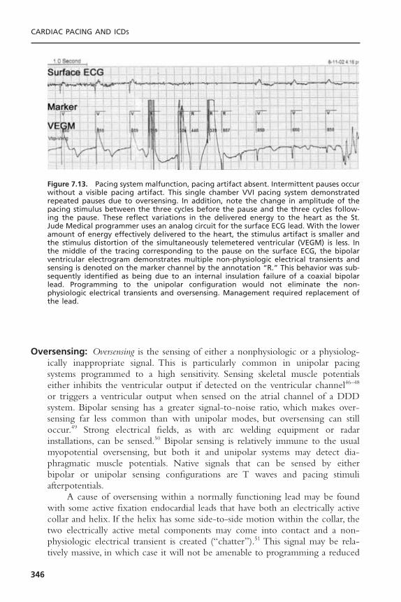
Oversensing: Oversensing is the sensing of either a nonphysiologic or a physiolog-ically inappropriate signal. This is particularly common in unipolar pacingsystems programmed to a high sensitivity. Sensing skeletal muscle potentialseither inhibits the ventricular output if detected on the ventricular channel46–48
or triggers a ventricular output when sensed on the atrial channel of a DDDsystem. Bipolar sensing has a greater signal-to-noise ratio, which makes over-sensing far less common than with unipolar modes, but oversensing can stilloccur.49 Strong electrical fields, as with arc welding equipment or radar installations, can be sensed.50 Bipolar sensing is relatively immune to the usualmyopotential oversensing, but both it and unipolar systems may detect dia-phragmatic muscle potentials. Native signals that can be sensed by either bipolar or unipolar sensing configurations are T waves and pacing stimuli afterpotentials.
A cause of oversensing within a normally functioning lead may be foundwith some active fixation endocardial leads that have both an electrically activecollar and helix. If the helix has some side-to-side motion within the collar, thetwo electrically active metal components may come into contact and a non-physiologic electrical transient is created (“chatter”).51 This signal may be rela-tively massive, in which case it will not be amenable to programming a reduced
CARDIAC PACING AND ICDS
346
Figure 7.13. Pacing system malfunction, pacing artifact absent. Intermittent pauses occurwithout a visible pacing artifact. This single chamber VVI pacing system demonstratedrepeated pauses due to oversensing. In addition, note the change in amplitude of thepacing stimulus between the three cycles before the pause and the three cycles follow-ing the pause. These reflect variations in the delivered energy to the heart as the St.Jude Medical programmer uses an analog circuit for the surface ECG lead. With the loweramount of energy effectively delivered to the heart, the stimulus artifact is smaller andthe stimulus distortion of the simultaneously telemetered ventricular (VEGM) is less. Inthe middle of the tracing corresponding to the pause on the surface ECG, the bipolarventricular electrogram demonstrates multiple non-physiologic electrical transients andsensing is denoted on the marker channel by the annotation “R.” This behavior was sub-sequently identified as being due to an internal insulation failure of a coaxial bipolarlead. Programming to the unipolar configuration would not eliminate the non-physiologic electrical transients and oversensing. Management required replacement ofthe lead.

sensitivity even though reducing the sensitivity is usually effective managementfor the physiologic but inappropriate signals such as myopotentials.
Reducing the sensitivity to eliminate oversensing of physiologic but inap-propriate signals such as myopotentials or T waves, is recommended only if thenative signal for which sensing is desired is sufficiently large to allow it to con-tinue to be appropriately sensed. If reducing the sensitivity will result in under-sensing of appropriate signals, one might program the pacemaker to the triggeredmode. This will result in a stimulus being triggered rather than being inhibitedby oversensing.The “upper rate limit” in the triggered mode will be controlledby the refractory period.
Similar to the generation of nonphysiologic signals in the normally func-tioning coaxial bipolar leads, a break in the integrity of the inner insulation ofan in-line bipolar lead can result in similar nonphysiologic electrical transientsthat can be sensed. As both conductors are integral to the generation of thefalse signal, the oversensing will persist in both the bipolar and unipolar sensingconfiguration. When recorded via telemetered EGMs, these signals are often
EVALUATION AND MANAGEMENT OF PACING SYSTEM MALFUNCTIONS
347
Figure 7.14. In assessing the presence or absence of pacing stimuli and even native com-plexes, it is imperative to examine multiple leads, recorded either simultaneously orsequentially. Leads I, II, and III are recorded sequentially from a patient with a dual unipo-lar DDD pacing system. The pulse generator was located in the left pectoral fossa. Thebasic dipole of the pacing stimuli is parallel to lead III, resulting in the expected largeunipolar signals. In lead II, the atrial stimulus is virtually perpendicular to the lead, andthus no stimulus is recorded. In fact, had only lead II been monitored, the rhythm wouldhave been interpreted as P wave synchronous ventricular pacing. In lead I, two pacingstimuli are readily visible, but the ventricular evoked potential is virtually isoelectric. Hadthis been the only lead monitored, one might have mistakenly made the diagnosis ofventricular noncapture. The multiple leads confirm AV sequential pacing with normalcapture. To the right of the rhythm strips, a schematic of the pacing system is dia-grammed within Einthoven’s triangle. RA is right arm, LA is left arm, and IL is left leg ofthe standard ECG leads.

massive (>20mV), precluding their elimination by a simple reduction in sensi-tivity (see Fig. 7.4). The only short-term option for a totally pacemaker-dependent patient is to program the pacemaker to the asynchronous or triggered mode. Definitive management requires lead replacement.
When presented with recurrent pauses in the absence of pacing stimuli,one can quickly differentiate oversensing from the other causes of the absence
CARDIAC PACING AND ICDS
348
Table 7.3. Differential Diagnosis of Pauses—Pacing Stimuli Absent
Etiology Diagnostic Evaluation Management
Oversensing Magnet application (pauses Reduce sensitivity or • T wave, P wave, R wave eliminated), reduce program to bipolar sensing• Myopotential/diaphragm sensitivity configuration, replace with• Pacing afterpotential bipolar sensing lead• EMI• Crosstalk• Make-break potentials
Open circuit Lead impedance—high Apply pressure dressing (air • Conductor fracture Magnet—pauses persist in pocket), reprogram to • Loose set-screw Chest radiograph—terminal unipolar, replace lead,• Air in pocket (unipolar pin not seated properly, reoperate to tighten set
system) lateral may visualize air in screw• Lead pin/header pocket, conductor coil
mismatch discontinuity
Internal insulation failure Lead impedance low Program to unipolar until (<250ohms) lead can be replaced
Magnet—pauses persistChest radiograph—normal
or conductor coil deformity
Component malfunction Magnet—pauses persist Replace pulse generator,Telemetry—inconsistencies operative reassessment of
in measured data lead function before pulsegenerator
Pseudomalfunction Native rate slower than Reassurance as normal • Hysteresis paced rate function• Mode switching Pauses follow only sensed • PMT intervention beats
Interrogation of programmedparameters
Source: Modified from Levine PA. Pacing system malfunction: evaluation and management. In: PodridPJ, Kowey PR, eds. Cardiac Arrhythmia: Mechanisms, Diagnosis, and Management. Philadelphia:Williams& Wilkins, © 1995. By permission of Williams & Wilkins.

of pacing artifact by applying a magnet to the pacemaker.The magnet will causethe pacemaker to revert to asynchronous function. If the pauses are eliminated,the problem is that of oversensing.To determine the source of the oversensing,it is sometimes necessary to record the surface ECG while the patient is in theenvironment in which the reported symptoms occur. It may be necessary tohave the patient perform provocative maneuvers as were described earlier in thesection on lead evaluation. One could also have the patient do upper extrem-ity isometric exercises, tensing the pectoral muscles, or do sit ups to tighten theabdominal muscles in the case of an abdominal implant. The patient should beasked to take very deep breaths if diaphragmatic oversensing is suspected.Thesemaneuvers should be performed while continuously monitoring the rhythmand, if available, in conjunction with telemetered event markers and elec-trograms.
Open Circuit: This is second to oversensing as a cause of pauses associated withthe absence of a pacing stimulus. Event marker telemetry will indicate that thepacemaker released a pulse. A simultaneously recorded ECG will be necessaryto demonstrate that this output pulse never reached the heart, as no stimulusartifact is recorded. Measured data telemetry will report an infinitely high stim-ulation impedance or a dramatic change from the baseline recordings. With anopen circuit, there is no current drain associated with the programmed output;thus, the battery current drain will decrease from baseline. Some systems canprovide lead impedance measurements on a beat-by-beat basis. Most of the otherdevices that provide non-invasive lead impedance measurements make individ-ual measurements on a couple of output pulses. Thus, repeated interrogationsmay be necessary to identify an intermittent problem.
Application of a magnet to the pacemaker will not restore pacing that hasfailed due to an open circuit because the pacemaker is already generating theoutput pulse. The problem is that this stimulus is unable to be delivered to theelectrode-myocardial interface. An open circuit has a number of possible causes.The most common is a conductor fracture. The second is a failure to tightenthe set-screw adequately. Rarely open circuits result from incompatibilitybetween the lead pin and the header connector of the pacemaker or a com-ponent problem within the pulse generator.
Pulse Generator Component Malfunction: Pulse generator component mal-function is very rare, and is probably the least frequent cause of a pacing systemmalfunction. When a systematic design problem predisposes the system to a particular problem, most manufacturers inform physicians by way of a safetyalert or technical memorandum.The diagnostic evaluation of a suspected com-ponent malfunction includes magnet application, which is unlikely to restore aneffective output. Where measured data telemetry is available, it might provideclues, such as the device producing inconsistent measurements or inaccessibleinformation. For example, a high lead impedance suggesting an open circuit but
EVALUATION AND MANAGEMENT OF PACING SYSTEM MALFUNCTIONS
349
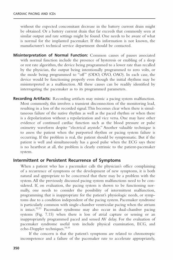
without the expected concomitant decrease in the battery current drain mightbe obtained. Or a battery current drain that far exceeds that commonly seen atsimilar output and rate settings might be found. One needs to be aware of whatis normal for the implanted pacemaker. If this information is not known, themanufacturer’s technical service department should be contacted.
Misinterpretation of Normal Function: Common causes of pauses associatedwith normal function include the presence of hysteresis or enabling of a sleepor rest rate algorithm, the device being programmed to a lower rate than recalledby the physician, the output being intentionally programmed to zero volts, orthe mode being programmed to “off ” (ODO, OVO, OAO). In each case, thedevice would be functioning properly even though the initial rhythms may bemisinterpreted as a malfunction. All these causes can be readily identified byinterrogating the pacemaker as to its programmed parameters.
Recording Artifacts: Recording artifacts may mimic a pacing system malfunction.Most commonly, this involves a transient disconnection of the monitoring lead,resulting in a loss of the recorded signal.This becomes clear when there is simul-taneous failure of the native rhythm as well as the paced rhythm or when thereis a depolarization without a repolarization and vice versa. One may have otherevidence of continued cardiac function such as the blood pressure or pulseoximetry waveform despite “electrical asystole.” Another valuable technique isto assess the patient when the purported rhythm or pacing system failure isoccurring. If the problem is real, the patient should be symptomatic. But if thepatient is well and simultaneously has a good pulse when the ECG says thereis no heartbeat at all, the problem is clearly extrinsic to the patient-pacemakersystem.
Intermittent or Persistent Recurrence of SymptomsWhen a patient who has a pacemaker calls the physician’s office complainingof a recurrence of symptoms or the development of new symptoms, it is bothnatural and appropriate to be concerned that there may be a problem with thesystem. All the previously discussed pacing system malfunctions need to be con-sidered. If, on evaluation, the pacing system is shown to be functioning nor-mally, one needs to consider the possibility of intermittent malfunction,programming that is inappropriate for the patient’s physiologic needs, or symp-toms due to a condition independent of the pacing system. Pacemaker syndromeis particularly common with single-chamber ventricular pacing when the atriumis intact.52,53 Pacemaker syndrome may also occur in dual-chamber pacingsystems (Fig. 7.15) when there is loss of atrial capture or sensing or an inappropriately programmed paced and sensed AV delay. For the evaluation ofpacemaker syndrome useful tests include physical examination, ECG, and echo-Doppler techniques.54,55
If the concern is that the patient’s symptoms are related to chronotropicincompetence and a failure of the pacemaker rate to accelerate appropriately,
CARDIAC PACING AND ICDS
350

enabling rate modulation or re-evaluating the rate modulated parameters wouldbe appropriate.
DUAL-CHAMBER PACING SYSTEM MALFUNCTIONThere are five major classes of dual-chamber pacing system malfunction. Thefirst class includes all the abnormalities previously discussed as occurring withsingle-chamber pacing systems. The abnormalities in this case occur on one orboth of the two channels of the dual-chamber system and, in recent years, thishas been extended to either lead in a multisite atrial or ventricular system.Although this may sometimes be obvious, there are situations in which theproblem will not be readily apparent because of the interaction of the pacedrhythm with the native conduction system while the patient remains asympto-matic.The second class consists of the unique rhythms that can occur only witha dual-chamber system, such as crosstalk and endless-loop tachycardia (ELT).The third class of problems occurs when the rate response sensor responds toa physiologically inappropriate signal, which in turn drives the pacemaker. Thismay also occur in single-chamber pacing systems. The fourth class of problemsis primarily due to a lack of understanding of the system and not appreciatingthe unique behavioral eccentricities of a pacemaker when it is functioningwithin its design specifications. The fifth group involves a mismatch between
EVALUATION AND MANAGEMENT OF PACING SYSTEM MALFUNCTIONS
351
A B
Figure 7.15. A: The patient was complaining of a persistent heaviness in his chest andchronic dyspnea with mild exertion. Atrial and ventricular capture thresholds were stableand low. An atrial-evoked response is not visible in this lead at the programmed AV delay.B: Increasing the AV delay unmasked the evoked atrial depolarization. There was markedlatency between the atrial stimulus and the resultant P wave. At the original pro-grammed AV delay (shipped value of the manufacturer), the atrial depolarization coin-cided with the ventricular activation. Markedly lengthening the AV delay allowed foreffective atrial transport, a clinical improvement in cardiac output and alleviation of hissymptoms of chest heaviness and dyspnea. This is an example of dual-chamber pacemakersyndrome.
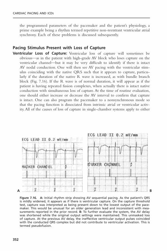
the programmed parameters of the pacemaker and the patient’s physiology, aprime example being a rhythm termed repetitive non-reentrant ventricular atrialsynchrony. Each of these problems is discussed subsequently.
Pacing Stimulus Present with Loss of CaptureVentricular Loss of Capture: Ventricular loss of capture will sometimes be
obvious—as in the patient with high-grade AV block who loses capture on theventricular channel—but it may be very difficult to identify if there is intactAV nodal conduction. One will then see AV pacing with the ventricular stim-ulus coinciding with the native QRS such that it appears to capture, particu-larly if the duration of the native R wave is increased, as with bundle branchblock (Fig. 7.16). If the R wave is of normal duration, it will appear as if thepatient is having repeated fusion complexes, when actually there is intact nativeconduction with simultaneous loss of capture. At the time of routine evaluation,one should either increase or decrease the AV interval to confirm that captureis intact. One can also program the pacemaker to a nonsynchronous mode sothat the pacing function is dissociated from intrinsic atrial or ventricular activ-ity. All of the causes of loss of capture in single-chamber systems apply to either
CARDIAC PACING AND ICDS
352
Figure 7.16. A: Initial rhythm strip showing AV sequential pacing. As the patient’s QRSis mildly widened, it appears as if there is ventricular capture. On the capture thresholdtest, capture was interpreted as being present down to the lowest output of the pace-maker. This would be unusual for an older generation lead and inconsistent with mea-surements reported in the prior record. B: To further evaluate the system, the AV delaywas shortened while the original output settings were maintained. This unmasked lossof capture. At the previous AV delay, the ineffective ventricular output pulses coincidedwith the conducted QRS complex but did not contribute to ventricular activation. This istermed pseudofusion.
A B
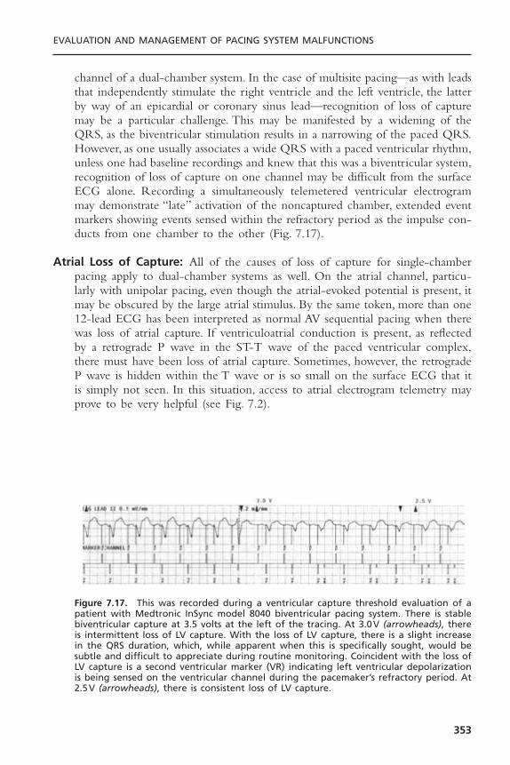
channel of a dual-chamber system. In the case of multisite pacing—as with leadsthat independently stimulate the right ventricle and the left ventricle, the latterby way of an epicardial or coronary sinus lead—recognition of loss of capturemay be a particular challenge. This may be manifested by a widening of theQRS, as the biventricular stimulation results in a narrowing of the paced QRS.However, as one usually associates a wide QRS with a paced ventricular rhythm,unless one had baseline recordings and knew that this was a biventricular system,recognition of loss of capture on one channel may be difficult from the surfaceECG alone. Recording a simultaneously telemetered ventricular electrogrammay demonstrate “late” activation of the noncaptured chamber, extended eventmarkers showing events sensed within the refractory period as the impulse con-ducts from one chamber to the other (Fig. 7.17).
Atrial Loss of Capture: All of the causes of loss of capture for single-chamberpacing apply to dual-chamber systems as well. On the atrial channel, particu-larly with unipolar pacing, even though the atrial-evoked potential is present, itmay be obscured by the large atrial stimulus. By the same token, more than one12-lead ECG has been interpreted as normal AV sequential pacing when therewas loss of atrial capture. If ventriculoatrial conduction is present, as reflectedby a retrograde P wave in the ST-T wave of the paced ventricular complex,there must have been loss of atrial capture. Sometimes, however, the retrogradeP wave is hidden within the T wave or is so small on the surface ECG that itis simply not seen. In this situation, access to atrial electrogram telemetry mayprove to be very helpful (see Fig. 7.2).
EVALUATION AND MANAGEMENT OF PACING SYSTEM MALFUNCTIONS
353
Figure 7.17. This was recorded during a ventricular capture threshold evaluation of apatient with Medtronic InSync model 8040 biventricular pacing system. There is stablebiventricular capture at 3.5 volts at the left of the tracing. At 3.0V (arrowheads), thereis intermittent loss of LV capture. With the loss of LV capture, there is a slight increasein the QRS duration, which, while apparent when this is specifically sought, would besubtle and difficult to appreciate during routine monitoring. Coincident with the loss ofLV capture is a second ventricular marker (VR) indicating left ventricular depolarizationis being sensed on the ventricular channel during the pacemaker’s refractory period. At2.5V (arrowheads), there is consistent loss of LV capture.

Programming to the AAI mode or functional AAI mode by reducing theventricular output to a subthreshold level will readily unmask atrial noncapture.However, this would not be safe to do in the presence of complete heart blockeven if the atrial capture were intact. In that setting a long PR interval may beprogrammed. If atrial sensing is present, it is possible to increase the rate toabove the native atrial rate. If there is capture, the sinus mechanism will be sup-pressed and there will be a stable AV sequential paced rhythm (Fig. 7.18). Ifatrial capture is absent, one will see AV pacing complexes alternating with PVcomplexes as the sinus P wave occurs during the atrial alert period. The avail-ability of telemetered electrograms in some systems has eliminated the need touse an esophageal lead to record an atrial electrogram to document atrial captureor noncapture. Use of an esophageal lead is still a potential option when theatrial output pulse saturates the electrogram precluding differentiating capturefrom loss of capture and other techniques prove ineffective.
CARDIAC PACING AND ICDS
354
Figure 7.18. To assess atrial capture in the patient with complete heart block, increasethe atrial rate above the native sinus rate. This will result in AV sequential pacing (top).As long as atrial capture is intact, the faster paced rate will overdrive–suppress the sinusmechanism. When loss of atrial capture occurs as the atrial output is intentionallyreduced, the sinus mechanism will escape; when it falls in an atrial alert period, it willbe sensed, triggering a ventricular output resulting in an irregular rhythm. There will beventricular pacing at all times, thus always protecting the patient. (Reprinted by permis-sion from Levine PA. Confirmation of atrial capture and determination of atrial capturethresholds in DDD pacing systems. Clin Prog Pacing Electrophysiol 1984;2:465–473.)

Dual-Chamber Pacing with Sensing MalfunctionSensing abnormalities in dual-chamber systems can result in inappropriate trig-gered pacing or inappropriate suppression of pacing depending on the pacingmode. The causes of sensing abnormalities include all those discussed undersingle-chamber systems. Functional undersensing is more common in dual-chamber systems due to the refractoriness in both chambers after each pacedor sensed event.A well-known historical example is committed DVI pacing witha total lack of atrial sensing and forced functional ventricular undersensingduring the AV delay. This occurs because the ventricular channel is renderedrefractory following release of the atrial output pulse. A relatively commonrecent example of both functional undersensing and functional loss of captureis repetitive non-reentrant ventriculoatrial synchronous rhythms.
Undersensing: Loss of atrial sensing when there is an intact sinus rhythm may bemore difficult to recognize in the dual-chamber system than in the single-chamber pacing system. For example, in the setting of a sufficiently rapid sinusrate, loss of atrial sensing in the DDD mode when there is intact AV nodal con-duction will result in functional DVI pacing with total pacing system inhibi-tion. The potential loss of atrial sensing will not become apparent unless thephysician programs the pacemaker to an AV interval that is shorter than theintrinsic conduction.
Atrial undersensing may occur in two settings postimplantation even whena good EGM was obtained at the time of pacemaker implantation. A decreasein the amplitude of the atrial EGM has been demonstrated in both animals andhumans during exercise.56 Thus, atrial undersensing might occur at the highersinus rates; yet at rest the atrial sensing threshold demonstrates a good marginof safety. Exercise and positional variations in P wave amplitude are also commonwith single-lead VDD systems using non-contact atrial electrodes. In addition,there may be a transient decrease in the amplitude of the atrial EGM occur-ring during the early electrode-maturation phase following implantation.Most cases of atrial undersensing occur in the first days or weeks postimplan-tation and will resolve spontaneously. As such, it would be prudent to observethe patient for weeks to months with the pacemaker programmed to a moresensitive setting before a decision is made to perform a repeat operative procedure.
On the ventricular channel, the ventricular stimulus may repeatedly fallwithin the native QRS, resulting in either a fusion or a pseudofusion complex.This may be normal because one cannot determine where the intrinsic deflec-tion (ID) that is sensed by the pacemaker occurs within the cardiac depolar-ization represented by the surface QRS complex. If the ID occurs late withinthe QRS, then the above behavior is normal. If it occurs before the AV inter-val timer has completed, the R wave should have been sensed and this behav-ior represents a malfunction. Unlike atrial undersensing, event marker telemetrywill not facilitate this assessment with the pacemaker in the DDD mode. Toevaluate ventricular sensing, one can increase the AV interval but only if
EVALUATION AND MANAGEMENT OF PACING SYSTEM MALFUNCTIONS
355
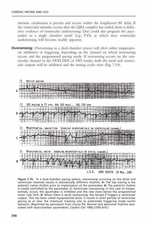
intrinsic conduction is present and occurs within the lengthened AV delay. Ifthe ventricular stimulus occurs after the QRS complex has ended, there is defin-itive evidence of ventricular undersensing. One could also program the pace-maker to a single chamber mode (e.g., VVI), at which time ventricularundersensing will become readily apparent.
Oversensing: Oversensing in a dual-chamber system will elicit either inappropri-ate inhibition or triggering, depending on the channel on which oversensingoccurs and the programmed pacing mode. If oversensing occurs on the ven-tricular channel in the DDD, DDI, or DVI modes, both the atrial and ventric-ular outputs will be inhibited and the timing cycles reset (Fig. 7.19).
CARDIAC PACING AND ICDS
356
Figure 7.19. In a dual-chamber pacing system, oversensing occurring on the atrial andventricular channels results in dramatically different rhythms. A: The top tracing is thepatient’s native rhythm prior to implantation of the pacemaker. B: The patient’s rhythmis totally controlled by the pacemaker. C: Ventricular oversensing, in this case of myopo-tentials, occurs; the pacemaker is inhibited and the rate slows below the programmedlower rate limit. D: When there is atrial oversensing, the sensed P triggers a ventricularoutput. This has been called myopotential drive; it results in brief periods of ventricularpacing at or near the maximum tracking rate or potentially triggering mode switchbehavior. (Reprinted by permission from Levine PA. Normal and abnormal rhythms asso-ciated with dual-chamber pacemakers. Cardiol Clin 1985;3:595–616.)
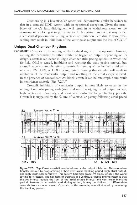
Oversensing in a biventricular system will demonstrate similar behaviors tothat in a standard DDD system with an occasional exception. Given the insta-bility of the CS lead, dislodgment will result in its withdrawal closer to thecoronary sinus placing it in proximity to the left atrium. As such, it may detecta left atrial depolarization causing ventricular inhibition. Left atrial P wave over-sensing may result in inhibition of the ventricular output and the loss of CRT.57
Unique Dual-Chamber RhythmsCrosstalk: Crosstalk is the sensing of the far-field signal in the opposite chamber,
causing the pacemaker to either inhibit or trigger an output depending on itsdesign. Crosstalk can occur in single-chamber atrial pacing systems in which thefar-field QRS is sensed, inhibiting and resetting the basic pacing interval, butcrosstalk most commonly refers to ventricular sensing of the far-field atrial stim-ulus in a DVI, DDI, or DDD pacing system. Sensing this stimulus will result ininhibition of the ventricular output and resetting of the atrial escape interval.In the presence of concomitant AV block, crosstalk can be catastrophic and resultin ventricular asystole (Fig. 7.20).58
Crosstalk inhibition of ventricular output is most likely to occur in thesetting of unipolar pacing leads (atrial and ventricular), high atrial output voltage,high ventricular sensitivity, and short ventricular blanking/refractory periods.Crosstalk is suggested by the failure of ventricular pacing following atrial-paced
EVALUATION AND MANAGEMENT OF PACING SYSTEM MALFUNCTIONS
357
Figure 7.20. Top: Classic crosstalk-mediated ventricular output inhibition. This was inten-tionally induced by programming a short ventricular blanking period, high atrial output,and high ventricular sensitivity. This patient had high-grade AV block, which is the worstsetting for crosstalk. The hallmark of crosstalk in a ventricular-based timing system is thatthe AA interval equals the sum of the atrial escape interval and ventricular blankingperiod. Bottom: In an atrial-based timing system, it may be difficult to differentiatecrosstalk from an open circuit. Crosstalk, in this example, was eliminated by increasingthe blanking period.
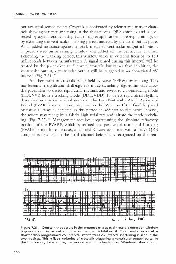
but not atrial-sensed events. Crosstalk is confirmed by telemetered marker chan-nels showing ventricular sensing in the absence of a QRS complex and is cor-rected by asynchronous pacing (with magnet application or reprogramming), orby extending the ventricular blanking period initiated by the atrial output pulse.As an added insurance against crosstalk-mediated ventricular output inhibition,a special detection or sensing window was added on the ventricular channel.Following the blanking period, this window varies in duration from 51 to 150milliseconds between manufacturers. A signal sensed during this interval will betreated by the pacemaker as if it were crosstalk, but rather than inhibiting theventricular output, a ventricular output will be triggered at an abbreviated AVinterval (Fig. 7.21).59
Another form of crosstalk is far-field R wave (FFRW) oversensing. Thishas become a significant challenge for mode-switching algorithms that allowthe pacemaker to detect rapid atrial rhythms and revert to a nontracking mode(DDI,VVI) from a tracking mode (DDD,VDD). To detect rapid atrial rhythm,these devices can sense atrial events in the Post-Ventricular Atrial RefractoryPeriod (PVARP) and in some cases, within the AV delay. If the far-field pacedor native R wave is detected in this period in addition to the native P wave,the system may recognize a falsely high atrial rate and initiate the mode switch-ing (Fig. 7.22).60 Management requires programming the absolute refractoryportion of the PVARP, which is termed the post-ventricular atrial blanking(PVAB) period. In some cases, a far-field R wave associated with a native QRScomplex is detected on the atrial channel before it is recognized on the ven-
CARDIAC PACING AND ICDS
358
Figure 7.21. Crosstalk that occurs in the presence of a special crosstalk detection windowtriggers a ventricular output pulse rather than inhibiting it. This usually occurs at ashorter-than-programmed AV interval. Intermittent AV-interval shortening is seen in thetwo tracings. This reflects episodes of crosstalk triggering a ventricular output pulse. Inthe top tracing, for example, the second and ninth beats show AV-interval shortening.

tricular channel. Circuits are being designed to manage this less common situ-ation but it cannot be managed by extending the PVAB.
Pacemaker-Mediated Tachycardias: A pacemaker-mediated tachycardia (PMT) is a tachycardia that is sustained by the continued active participation of thepacemaker in the rhythm. A PMT is not the same as a pacemaker-inducedtachycardia, in which the pacemaker induces a tachycardia by intentional orunintentional (undersensing) competition, but once the tachycardia has begun,the pacemaker is inhibited and no longer plays an active role in the rhythm.There are several forms of pacemaker-mediated tachycardias encountered inclinical practice. In the DDD mode, the normally functioning pacemaker is sup-posed to sense atrial activity and trigger a ventricular output in response to thedetected P wave. The DDD pacemaker in a patient in whom atrial fibrillationor flutter develops may track the pathologic atrial signals (e.g., flutter or
EVALUATION AND MANAGEMENT OF PACING SYSTEM MALFUNCTIONS
359
Figure 7.22. Surface ECG, atrial electrogram, ventricular electrogram, and event markersfrom a patient with a Guidant Discovery that was demonstrating inappropriate modeswitching due to far-field R wave oversensing. This recording was obtained during per-formance of the ventricular capture threshold test as part of the pacing system evalua-tion. A discrete deflection is visible on the atrial lead coincident with the QRS andidentified by the event markers (AS), which means that it is a sensed complex occurringwithin the refractory period. With loss of capture shown by the last complex on this,there is a disappearance of the second deflection on the AEGM and the marker (AS).Increasing the PVAB eliminated the far-field R wave sensing.

fibrillatory waves). This will drive the ventricular channel of the pacemaker ator near its maximum tracking rate (MTR).61
The first PMTs that became widely recognized in the literature were notdue to tracking atrial fibrillation or atrial flutter or oversensing on the atrialchannel. Instead, they were due to sensing retrograde atrial activity arising froma premature ventricular contraction (PVC).This set up a repetitive sequence ofthe sensed retrograde P wave triggering a ventricular output at the end of themaximum tracking rate interval.The delay created by waiting for the MTRI tocomplete before the ventricular stimulus was released allowed the atrium andAV node to physiologically recover. The depolarization resulting from a ven-tricular paced beat was again able to conduct in a retrograde direction.This nextretrograde P wave would be sensed, triggering another ventricular output andresulting in a sustained PMT.62,63 Because this resembled the endless loop thatcan be seen in computers, Furman and associates labeled this rhythm an endless-loop tachycardia (ELT) to differentiate it from the other forms of PMT.64 Themajority of PMTs in the literature are of the endless-loop variety, running eitherat or below the programmed maximum tracking rate (Fig. 7.23A).The onset ofELT requires at least transient AV dissociation to allow retrograde conductionto occur.Thus, the appearance of ELT should initiate a search for causes of AVdissociation such as atrial undersensing, atrial oversensing, loss of atrial capture,or magnet application to the pacemaker. Once initiated, an endless-loop pacemaker-mediated tachycardia will continue unless there is spontaneous VAblock or loss of atrial sensing.
Algorithms to prevent ELT extend the PVARP after a sensed ventricularevent that is not preceded by an atrial event (a PVC as defined by the pace-maker) to ensure that any retrograde P wave will fall in the refractory periodand not be tracked. A number of adverse rhythms have been associated withautomatic extension of the atrial refractory period, leading to sustained pace-maker inhibition with first-degree AV block and a PR interval significantlylonger than the programmed PV interval. This situation is created by a P wavecoinciding with the PVARP and hence not being sensed. However, the P waveis conducted and the sensed R wave is treated as a PVC by the pacemaker,extending the PVARP and again precluding sensing of the next P wave.Although disconcerting when encountered, it is not dangerous because thepatient has an intact native rhythm. To prevent ELT by using a long PVARPyet still allow tracking to high atrial rates some devices employ a rate variablePVARP that automatically shortens at higher rates. Another option is rateresponsive AV delay allowing the PVARP to be kept at a longer interval whilethe sensed AV delay shortens as the rate increases.
ELT may be automatically terminated by specialized algorithms (Fig. 7.24).These algorithms typically extend the PVARP or withhold a ventricular outputfor one cycle after tracking at the upper rate limit for a number of cycles andintermittently thereafter. If the tachycardia is due to ELT, it is terminated by thefailure to track the retrograde P wave. If tachycardia is due to sinus rhythm, thetracking will continue after a single missed beat.65
CARDIAC PACING AND ICDS
360

EVALUATION AND MANAGEMENT OF PACING SYSTEM MALFUNCTIONS
361
A
B
Figure 7.23. This figure shows both a pacemaker endless loop tachycardia (ELT) and arepetitive non-reentrant ventriculoatrial synchronous (RNRVAS) rhythm. These wererecorded from the same patient at the time of a follow-up evaluation. Both rhythmswere induced by careful programming of the pacemaker. The base rate was increased to90ppm during the atrial capture threshold test. A: To allow an ELT to occur in this patientwith known retrograde conduction, the PVARP was reduced to 125 milliseconds. Uponloss of atrial capture, there was full ventricular capture at the end of the AV delay fol-lowed by retrograde conduction. The retrograde P wave was detected by the atrialsensing circuit and triggered the next ventricular output after the sensed AV delay wasextended so as to not violate the programmed maximum tracking rate. This rhythmwould persist until the pacemaker was reprogrammed or an automatic ELT terminationalgorithm intervened (see Fig. 7.24). B: To demonstrate the RNRVAS rhythm, the AV delaywas increased to 300 milliseconds and the PVARP increased to preclude detection of theretrograde P wave. While the long PVARP will prevent an ELT, each subsequent atrialoutput pulse, even at full output, will be delivered at a time when the atrial myocardiumis physiologically refractory as schematically represented by a heavy solid line startingwith the native (retrograde) P wave as shown on the AEGM. The result is functional lossof capture. The top horizontal line within the event markers identifies the duration ofthe atrial refractory period. As each retrograde P wave coincides with the PVARP, thereis also functional undersensing. This alignment is identified by the thin double arrow.
A unique ELT has recently been described when a dual-chamber pace-maker is used to provide biventricular pacing where the CS lead is connectedto the atrial port and the RV lead is connected to the ventricular port. A PVCarising in the right ventricle will be labeled an R wave. This will trigger thePVARP but if conduction to the LV is delayed such that detection occurs after

the PVARP, the detected LV depolarization will be labeled a P wave and triggeran output in the RV. This is an example of an intraventricular PMT.66
Another pacemaker-mediated rhythm resulting from AV dyssynchrony isrepetitive non-reentrant ventriculoatrial synchronous rhythm. This rhythm rep-resents a mismatch between the alert and refractory periods of the pacemakerand the heart.67 It is functionally equivalent to VVI pacing with intact retro-grade conduction, but it occurs in the setting of AV pacing.The trigger for thisrhythm is identical to the initiating factors for an endless-loop tachycardia (i.e.,AV dissociation), that allow retrograde conduction to develop. In this rhythm,the PVARP is programmed to a sufficiently long interval to preclude the ret-rograde P wave from being detected; hence, a PMT does not begin. If the AVpaced rate is sufficiently rapid, whether this is due to a high programmed baserate or sensor-drive, the P wave occurring within the PVARP is not detected(functional undersensing) thus allowing the atrial escape interval to complete,resulting in the delivery of an atrial output pulse. At the high rate, the atrialescape interval is relatively short and may result in the delivery of an atrialoutput pulse at a time when the atrial myocardium is still refractory on a phys-iologic basis. This pattern may then be repetitive. A new algorithm called non-competitive atrial pacing has been introduced in an attempt to preclude such a
CARDIAC PACING AND ICDS
362
Figure 7.24. Stored EGM from a Guidant Pulsar Max II demonstrating the recognitionand automatic termination of an endless loop tachycardia (ELT). Top tracing: atrial elec-trogram (A-EGM). Middle tracing: ventricular EGM. Bottom tracing: marker channel.Guidant’s algorithm extends the PVARP after a number of cycles of atrial sense-ventriclepace (AS-VP) at the maximum tracking (MT) rate. If this rhythm were an ELT, the extendedPVARP will preclude responding to the retrograde P wave and prompt termination ofthe rhythm as occurred. AS denotes atrial event in the refractory period. If the etiol-ogy of the atrial events was sinus tachycardia or an intrinsic atrial tachycardia in thesetting of high-grade AV block, the extended PVARP would result in a pause due to thelack of tracking of the “blocked” P wave followed by prompt resumption of the rapidrhythm.
rhythm by extending atrial output to at least 300 milliseconds after an atrialsensed event (Fig. 7.23B).
UNIQUE BIVENTRICULAR RHYTHMS WITH LOSS OF CAPTUREWhen one considers pacing, recognition of a wide QRS is expected, particu-larly in association with ventricular pacing. In biventricular pacing, the pacedcomplex will be abnormal but usually narrower than the “usual” paced ven-tricular complex. Unless one has a baseline 12-lead ECG for comparison, thismay not be recognized as normal.The LV capture threshold tends to be higherthan the RV threshold. LV pacing is usually achieved via a lead placed in thecoronary sinus. The fixation mechanisms in this position are not as secure asthose associated with endocardial pacing. As such, both lead dislodgment andloss of capture are more common with LV leads than with RV leads. With lossof LV capture, one may see an “obviously” paced ventricular beat. Unless onewas aware of the baseline recordings for the patient or that the patient had abiventricular system, loss of capture will not be recognized (see Fig. 7.17). Thepresentation is also likely to differ from that of the patient with a pacemakerimplanted for high grade AV block who develops loss of capture. Patients whoare paced for cardiac resynchronization have congestive heart failure. Thus, theloss of CRT may manifest itself as a worsening of their congestive symptomswhile the rhythm is intact.
PACEMAKER ECCENTRICITIES AND PSEUDOMALFUNCTIONA pacemaker eccentricity is a unique behavior of the pacemaker that would beunexpected based on a knowledge of the pacing mode but that is normal forthat model of pacemaker. A pseudomalfunction is a misdiagnosed problem withpacemaker function that in fact results from normal operation of a pacemakeralgorithm or function. The eccentricities of pacemaker function are often notpopularized in the literature or the physician’s manual for the device. They arefrequently brought to the attention of the physician only after consulting withtechnical support for the manufacturer regarding an unexplained pacemakerbehavior. Examples are shown in Figure 7.25. Pseudomalfunctions are a chal-lenge for even the seasoned pacemaker physician given the increasing com-plexity of the newer devices with less than obvious interactions betweenavailable algorithms. A list of common features causing pseudomalfunctions incurrent pacemaker systems is shown in Box 7.4.
PACEMAKER DIAGNOSTICSGiven the multiplicity of confusing pacemaker rhythms, most manufacturersinclude various aids within the pacemaker to assist the physician in evaluatingthe system. These include both real-time diagnostic aids as well as system-overview capabilities. Many real-time diagnostic capabilities have been discussed
EVALUATION AND MANAGEMENT OF PACING SYSTEM MALFUNCTIONS
363
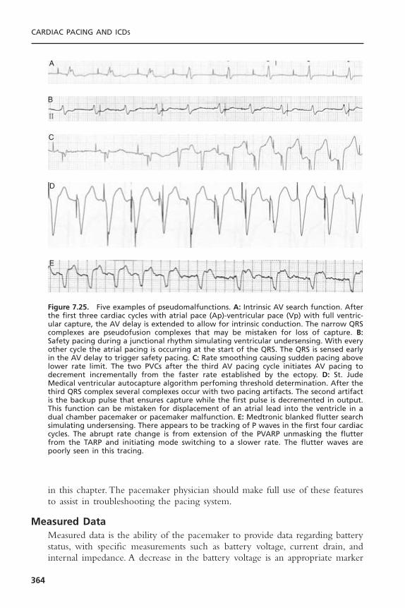
in this chapter. The pacemaker physician should make full use of these featuresto assist in troubleshooting the pacing system.
Measured DataMeasured data is the ability of the pacemaker to provide data regarding batterystatus, with specific measurements such as battery voltage, current drain, andinternal impedance. A decrease in the battery voltage is an appropriate marker
CARDIAC PACING AND ICDS
364
A
B
C
D
E
Figure 7.25. Five examples of pseudomalfunctions. A: Intrinsic AV search function. Afterthe first three cardiac cycles with atrial pace (Ap)-ventricular pace (Vp) with full ventric-ular capture, the AV delay is extended to allow for intrinsic conduction. The narrow QRScomplexes are pseudofusion complexes that may be mistaken for loss of capture. B:Safety pacing during a junctional rhythm simulating ventricular undersensing. With everyother cycle the atrial pacing is occurring at the start of the QRS. The QRS is sensed earlyin the AV delay to trigger safety pacing. C: Rate smoothing causing sudden pacing abovelower rate limit. The two PVCs after the third AV pacing cycle initiates AV pacing todecrement incrementally from the faster rate established by the ectopy. D: St. JudeMedical ventricular autocapture algorithm perfoming threshold determination. After thethird QRS complex several complexes occur with two pacing artifacts. The second artifactis the backup pulse that ensures capture while the first pulse is decremented in output.This function can be mistaken for displacement of an atrial lead into the ventricle in adual chamber pacemaker or pacemaker malfunction. E: Medtronic blanked flutter searchsimulating undersensing. There appears to be tracking of P waves in the first four cardiaccycles. The abrupt rate change is from extension of the PVARP unmasking the flutterfrom the TARP and initiating mode switching to a slower rate. The flutter waves arepoorly seen in this tracing.

EVALUATION AND MANAGEMENT OF PACING SYSTEM MALFUNCTIONS
365
Box 7.4. Pacemaker Functions Associated with Pseudomalfunctions
Pacing When Not Expected Diagnostic Clue— Rate smoothing — Graded rate slowing toward lower rate limit— Rate drop response — Abrupt pacing 90–110bpm after sudden
slowing— Dynamic atrial overdrive — Atrial pacing after atrial ectopy— Ventricular rate regularization — Pacing after shorter V-V intervals in atrial
fibrillation— Ventricular based timing — Faster ventricular rate during ApVs–ApVp
cycle— Safety pacing — Ventricular pacing with shortened AV delay— Separate mode switch rate or — Pacing during or after atrial tachyarrhythmia
post mode switch or oversensingoverdrive rate
— Atrial pace for AV — Pacing simultaneous with PVC or delayed resynchronization after atrial ectopy
— QT sensor check — QT rate sensor active— Atrial pacing preference — Atrial pacing after atrial sensed events— Automated capture — Closely coupled stimuli during QRS
determinations
No Pacing When Expected— Hysteresis — Pause after sensed events— Rate smoothing — Graded rate acceleration toward upper rate
limit— PMT intervention — Ventricular output absent after As-Vp at
upper rate limit— Mode switching — Failure to track atrial activity— Intrinsic AV conduction search — Periodic extension of AV delay— Non-competitive atrial pacing — Delay in atrial output following atrial sense
in PVARP— Separate sleep rate — Reduced lower rate limit at rest— Atrial based timing — Prolongation of V-V interval during ApVs–
ApVp cycle— Automatic sensing check — Periodic delay in pacing after prolonged
pacing
Apparent Undersensing— Mode switching — Failure to track atrial activity— PMT intervention — Failure to track single P wave during
prolonged AsVp at upper rate limit— Rate adaptive AV delay — Evidence of shorter AV delays at faster rates— Non-tracking modes (DDI, — Typical non-tracking mode behavior
DVI, etc.)— Blanked flutter search — Failure to track P wave when atrial tracking
at rate <2 times TARP— Noise mode — Evidence of EMI
to identify the point at which there is an increase in the frequency of pace-maker surveillance for signs of battery depletion.68
Measured data also includes measurements of pulse voltage, charge, current,energy, and stimulation impedance. Lead or stimulation impedance measure-ments may be particularly helpful in identifying an open circuit, which will beassociated with a very high impedance (see Fig. 7.7) or a breach of the inter-nal insulation of a bipolar coaxial lead, in which case, the impedance will bevery low.69,70 One should be cautious with respect to this information. A mea-surement that is significantly changed from previous results should be recon-firmed to eliminate a telemetry error.
Event MarkersEvent markers have been shown in multiple figures in this chapter.These com-prise timing information telemetered from the pacemaker to the programmerand are displayed on a screen or printed. Basically, these markers are a report ofwhat the pacemaker is doing. Unique notations or marks are generated for pacedand sensed events; in some cases, marks are generated for events occurringduring the refractory period as well as an indication of refractory period duration.71–73
Event markers are an extremely powerful tool, especially when combinedwith the simultaneously recorded electrocardiogram. Pauses can be identified asdue to oversensing or an open circuit, as shown in Figure 7.7.With diminutivebipolar output pulses that may not be visible on the standard electrocardiogram,telemetered event markers will identify whether the P wave or QRS complexis paced or sensed. The ECG also confirms the response to a pacing stimulus.
ElectrogramsThe ability to examine the endocardial electrogram (EGM) is very helpful inidentifying false signals that are being sensed (oversensing), as shown in Figure7.4, or in confirming the presence of signals that are not readily identified onthe surface ECG, as in Figures 7.2 and 7.17. Some physicians have recommendedusing the telemetered electrogram as a way of performing a sensing thresholdevaluation,74 but this may be inappropriate. Some systems do not provide a cal-ibration scale; others use a different set of filters in the telemetry amplifier com-pared with those used in the sense amplifier. In these settings, although theremay generally be a close correlation between the amplitude of the telemeteredelectrogram, there may also be marked discrepancies due to the different filters.
Electrograms may also provide clues as to why there is a sensing problemor why the noninvasively measured sensing threshold is obtained by progres-sively reducing the sensitivity until intermittent or persistent failure to sense isdemonstrated.75,76 This, however, requires the additional capability of adjustingboth the gain and the sweep speed of the signal once it has been frozen.Whendisplayed at a relatively slow recording speed, a complex may look very goodwith a large amplitude; however, when the signal is displayed at a faster sweepspeed, it may be shown to be splintered and/or have segments that are com-
CARDIAC PACING AND ICDS
366
posed of predominantly low-frequency components, with the actual rapidintrinsic deflection being of relatively low amplitude. An example is shown inFigure 7.26. One also needs to be aware that there are two basic electrograms.One reflects the signal after it has been processed by the sense amplifier limit-ing any morphologic information and may not be calibrated.The other utilizesa relatively broad band-pass filter and although calibrated, the peak-to-peak mea-surement may not reflect the amplitude of the signal as detected by the sensingcircuit because of different filters.
Stored DataMeasured data, event markers, and electrogram telemetry are all considered real-time data. However, if the problem is intermittent, the real-time data may beentirely normal; in such cases, a more extensive evaluation will be required.Further, the real-time diagnostics may identify a developing pacing systemproblem but one that has not yet resulted in any adverse consequences for thepatient.Additional evaluation or even intervention might be warranted, depend-ing on the specific clinical setting. Although stored EGMs triggered by specificevents have been a mainstay of ICD diagnostics for almost a decade, they haveonly been recently introduced to bradycardia devices.77 EGM storage may betriggered by magnet application by the patient or automatically by the devicein response to rapid heart rates.
Event CountersEvent counters provide information about the function of the pacing systemover time. This feature may provide an overview of the behavior of the pacingsystem with respect to specific events or activation of various algorithms, anoverview of the general behavior of the system, or a report of the pacing systemwith respect to time. Each manufacturer has its own set of unique labels for thespecific counters in its various products, but, generically, there are three sepa-rate capabilities.
Total System Performance Counters: Total system performance counters reportthe total number of events within each pacing state (atrial sense–ventricularsense, atrial pace–ventricular sense, etc.), sometimes with a further separation asto rate distribution within each pacing state.78 Many systems will also report thenumber of premature ventricular sensed events. The potential value to themedical staff caring for the patient is that these counters provide an overviewof the behavior of the pacing system since the last evaluation. The interpreta-tion of these counters requires knowledge of the patient’s clinical status and the integrity of capture and sensing within the pacing system (Fig. 7.27). Forexample, if the system reports that all the complexes were paced in the ventricle, either AV or PV, it is a report of the pacemaker’s behavior. Loss ofatrial or ventricular capture cannot be ascertained from these counters, and atrue pacing system problem might go unrecognized if one relies only on thecounters.
EVALUATION AND MANAGEMENT OF PACING SYSTEM MALFUNCTIONS
367
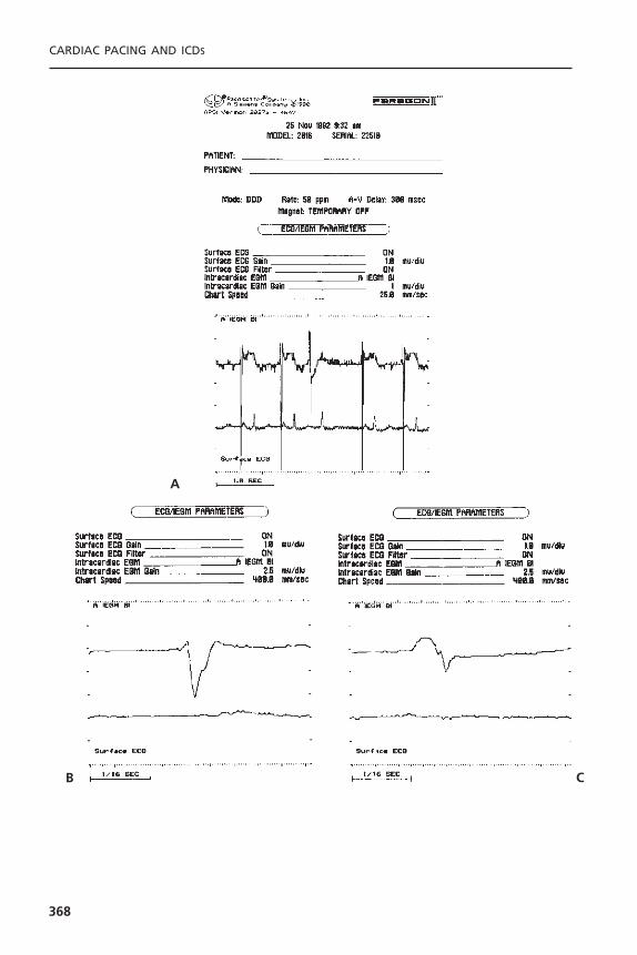
CARDIAC PACING AND ICDS
368
A
B C
If the pacing system is functioning properly with respect to capture andsensing, the total system performance counters provide insight as to chronotropicfunction based on the distribution of sensed atrial activity, the response of thesensor, the percentage of time the sensor is controlling the pacemaker, and thestatus of AV nodal conduction based on the percentage of paced and sensedcomplexes. Frequent “PVCs” at a low rate may be a marker for intermittentatrial undersensing with intact AV nodal conduction or for accelerated junc-tional rhythms; a large number of PVCs at a high rate may reflect true ven-tricular ectopic beats. The data provided by all the event counters need to becorrelated with the clinician’s knowledge of the patient.
Subsystem Performance Counters: Subsystem performance counters track andreport the behavior of specific algorithms or features of the pacing system.Theseinclude, but are not limited to, sensor-indicated rates, number of times the PMTalgorithm was activated, the amount of time spent at the programmed maximaltracking rate, the number of automatic mode switch episodes, the peak atrialrates that triggered the mode-switch episodes or occurred above a predefinedrate, atrial or ventricular high rate episodes, sensor-indicated rates, and a long-term threshold record for those systems with automatic capture assessment algo-rithms.79 The value of these counters is that they separate specific events fromthe overall total system performance counter and provide information withrespect to the frequency with which that algorithm or feature was used. Theseevent counters may also provide data that are not obtainable from a standardECG or Holter monitor.
These counters may be displayed as a summary total, a table of events, ahistogram, or a more detailed presentation of each event, depending on thedesign of the specific counter and the information that is stored. An exampleof a subsystem performance counter is shown in Figures 7.28 and 7.29.
Time-Based System Performance Counters: A limitation of both the total andsubsystem performance counters when the data are displayed in either a cumu-lative table or histogram format is that specific events will be lost within theoverall mass of data. A third counter capability places each of the individual
EVALUATION AND MANAGEMENT OF PACING SYSTEM MALFUNCTIONS
369
Figure 7.26. A: Bipolar atrial electrogram with a simultaneously recorded surface ECG.There is an isolated atrial premature beat that appears to be at least 3mV in amplitudebut, when the sensing threshold was assessed, there was intermittent failure to sense at1mV. The sensing threshold for the sinus P wave was greater than 5mV. B: Increase inthe sweep speed to 400mm/sec and a reduction in the gain to 2.5mV/division. This atrialelectrogram represents the sinus P wave and it corresponds to the noninvasively mea-sured sensing threshold. C: Increase in the sweep speed to 400mm/sec and a reductionin the gain to 2.5mV/division. This atrial electrogram represents the atrial prematurebeat. Much of the amplitude noted when the sweep speed was 25mm/sec was composedof very low-frequency components. The complex is also splintered with a slew rate sig-nificantly lower than the sinus complex, accounting for the intermittent undersensing ata 1-mV sensitivity.
�

CA
RD
IAC
PAC
ING
AN
D IC
DS
370
Rate (ppm) PV PR AV AR PVE 30–54 3,699 546,503 28,834 209,108 22455–69 13,626 2,381,502 70,236 617,575 1670–89 13,202 10,374,285 242 11 5090–109 8,650 7,341,430 0 0 478110–129 70,477 263,498 0 0 4,889130–149 27 6,001 0 0 2,538150–179 0 1,689 0 0 770180–224 0 1,369 0 0 16225–249 0 1,241 0 0 0> 250 0 777 0 0 0
Total 109,681 20,918,295 99,312 821,694 8,981
Per
cent
Tim
e
Rate (ppm)
Heart Rate Histogram, Percent of Time Per Rate Bin
30 55 70 90 110 130 150 180 225 250 > 250
Per
cent
Tim
e
Rate (ppm)
Sensed (PV/PR)
Paced (AV/AR)
PVE
Heart Rate Histogram, Percent of Total Time
Heart Rate Histogram – Initial
30
718
47
27
1 <1 <1 <1 <1 <1
55 70 90 110 130 150 180 225 250 > 250
Per
cent
Tim
e
Rate (ppm)
Event Histogram, Percent of Total Time
Total Event Count: 21,957,963
Event Histogram – Initial
Event Counts – Initial
94
1 <1 5 <1
PV PR AV AR PVE
Figure 7.27. Total system performance counter (Event Histogram) from a St. Jude Medical Integrity 5342 pulse generator demon-strating the relative distribution of pacing states, the heart rate based on atrial events (paced or sensed), the absolute number ofevents in each pacing state at each rate bin over the preceding 192 days, 7 hours, 23 minutes, and 20 seconds. The PVE in thiscounter reflects events that the pacemaker will treat as PVCs. As these may also be junctional beats, episodes of atrial undersensingwith intact conduction, or noise on the ventricular channel and not a true PVC as would be implied to the clinical staff, these arelabeled PVEs. Key programmed parameters and system statistics are displayed toward the top of the printout.
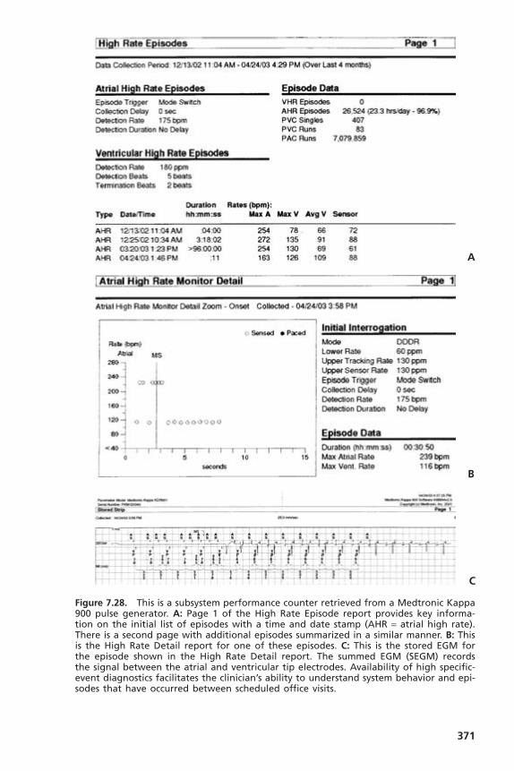
371
A
B
C
Figure 7.28. This is a subsystem performance counter retrieved from a Medtronic Kappa900 pulse generator. A: Page 1 of the High Rate Episode report provides key informa-tion on the initial list of episodes with a time and date stamp (AHR = atrial high rate).There is a second page with additional episodes summarized in a similar manner. B: Thisis the High Rate Detail report for one of these episodes. C: This is the stored EGM forthe episode shown in the High Rate Detail report. The summed EGM (SEGM) records the signal between the atrial and ventricular tip electrodes. Availability of high specific-event diagnostics facilitates the clinician’s ability to understand system behavior and epi-sodes that have occurred between scheduled office visits.

events in the specific sequence of their occurrence.These are classified as time-based system performance counters (Fig. 7.30).They have many names, includ-ing “rolling trend” and “event record.”
There are two subsets to the time-based system performance counter. Oneis that specific events such as activation of a unique algorithm trigger storageof that event for retrieval at a later date. These are often associated with a timeand date stamp (see Fig. 7.28). These, however, will not recognize a symptom-atic event that does not also invoke one of the special algorithms in the device.
CARDIAC PACING AND ICDS
372
Figure 7.29. Long-term threshold record from a patient with a St. Jude Medical Affin-ity DR pulse generator with AutoCapture enabled. This is another subsystem performancecounter. In this case, it demonstrates a protracted period of a stable low capture thresh-old in the range of 0.75V. An abrupt marked increase in the capture threshold occurred1 week before a scheduled follow-up evaluation. The time course of the threshold risecorrelated with an episode of severe acute gastroenteritis resulting in dehydration andmarked electrolyte imbalance necessitating hospitalization for a period of 3 days for fluidresuscitation and stabilization. No problems had been suspected with the pacing systemand the marked threshold rise was only recognized in retrospect. Had AutoCapture notbeen enabled and the pacemaker programmed to the standard 2 :1 safety margin, therewould have been loss of capture. (Reprinted by permission from Levine PA. Guidelinesto the Routine Evaluation, Programming and Follow-up of the Patient with an ImplantedDual-Chamber Rate-Modulated Pacing System. Sylmar, CA: St. Jude Medical CRMD, 2003.)
Figure 7.30. A combination of a subsystem and time-based system performance counterfrom Guidant providing a date stamp for periodic automatic measurements of signalamplitudes and stimulation impedances. This is displayed in both tabular and graphicformats. The total duration of this diagnostic is one year. After that, as new data areadded, the oldest data are deleted. Where a signal is not available for measurementbecause of pacing, the value is reported as NR. When pacing is absent due to continuedsensing, the impedance value is reported as NR.
�

EVALUATION AND MANAGEMENT OF PACING SYSTEM MALFUNCTIONS
373
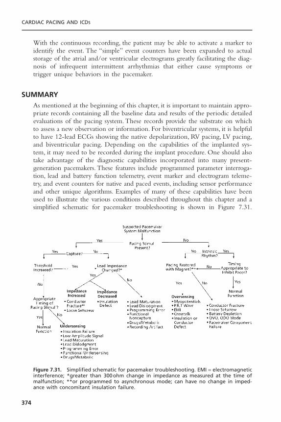
With the continuous recording, the patient may be able to activate a marker toidentify the event. The “simple” event counters have been expanded to actualstorage of the atrial and/or ventricular electrograms greatly facilitating the diag-nosis of infrequent intermittent arrhythmias that either cause symptoms ortrigger unique behaviors in the pacemaker.
SUMMARYAs mentioned at the beginning of this chapter, it is important to maintain appro-priate records containing all the baseline data and results of the periodic detailedevaluations of the pacing system. These records provide the substrate on whichto assess a new observation or information. For biventricular systems, it is helpfulto have 12-lead ECGs showing the native depolarization, RV pacing, LV pacing,and biventricular pacing. Depending on the capabilities of the implanted sys-tem, it may need to be recorded during the implant procedure. One should alsotake advantage of the diagnostic capabilities incorporated into many present-generation pacemakers. These features include programmed parameter interroga-tion, lead and battery function telemetry, event marker and electrogram teleme-try, and event counters for native and paced events, including sensor performanceand other unique algorithms. Examples of many of these capabilities have beenused to illustrate the various conditions described throughout this chapter and asimplified schematic for pacemaker troubleshooting is shown in Figure 7.31.
CARDIAC PACING AND ICDS
374
Figure 7.31. Simplified schematic for pacemaker troubleshooting. EMI = electromagneticinterference; *greater than 300ohm change in impedance as measured at the time ofmalfunction; **or programmed to asynchronous mode; can have no change in imped-ance with concomitant insulation failure.

Although these features are helpful, there is no substitute for a thorough under-standing of the pacing system, the patient, and the fundamental concepts ofpacing.
When a true pacing system malfunction is encountered, the full differen-tial diagnosis should be considered.This includes primary problems arising withthe pulse generator, the lead(s), and the patient, as well as the interaction betweenthese three components. It is embarrassing, expensive, and potentially dangerousto subject the patient to an operative procedure to replace a normally func-tioning pacemaker when the observed “problem” could have been easily cor-rected by programming the pacemaker or reflected a system eccentricity andwas normal.Thus, any prior data that are available should be reviewed, the pro-grammed parameters of the pacing system should be obtained, and all availablediagnostic features of the given device should be used before arriving at a finaldecision and plan. If there are still concerns, each manufacturer provides 24/7technical support before deciding on an operative intervention. To do less thanthis may result in an incorrect diagnosis—to the detriment of the patient, thephysician, and the overall healthcare economy.
REFERENCES1. Song SL. The Bilitch report: performance of implantable cardiac rhythm manage-
ment devices. Pacing Clin Electrophysiol 1994;17:692–704.2. Furman S, Benedek ZM, Andrews CA, et al. Long-term follow-up of pacemaker
lead system. Pacing Clin Electrophysiol 1995;18:271–285.3. Levine PA.The complementary role of electrogram, event marker and measured data
telemetry in the assessment of pacing system function. J Electrophysiol 1987;1:404–416.
4. Ohm OJ, Breivik K, Hammer EA, et al. Intraoperative electrical measurementsduring pacemaker implantation. Clin Prog Pacing Electrophysiol 1984;2:1–23.
5. Arnold AG. Predictive value of ST segment elevation in cardiac pacing. Br Heart J1980;44:416–418.
6. Levine PA, Schuller H, Lindgren A. Pacemaker ECG—an introduction and approachto interpretation. Solna, Sweden: Siemens-Pacesetter, 1986.
7. Sheffield LT, Berson AL, Bragg-Remschel D, et al. AHA special report: recommen-dation for standards of instrumentation and practice in the use of ambulatory elec-trocardiography. Circulation 1985;71:626A–636A.
8. Cherry R, Sactuary C, Kennedy HL.The question of frequency response.Amb Elec-trocardiol 1977;1:13–14.
9. Hecht SR, Berdoff RL. Radiographic recognition of pacemaker lead complications.Clin Prog Electrophysiol Pacing 1986;4:189–198.
10. Veltri EP, Mower MM, Reid PR. Twiddler’s syndrome: a new twist. Pacing ClinElectrophysiol 1984;7:1004–1009.
11. Furman S, Pannizzo F, Campo I. Comparison of active and passive adhering leadsfor endocardial pacing. Pacing Clin Electrophysiol 1979;2:417–427.
12. Trautwein W. Electrophysiological aspects of cardiac stimulation. In: Schaldach M,Furman S, eds. Advances in Pacemaker Technology. New York: Springer-Verlag,1975:11–23.
EVALUATION AND MANAGEMENT OF PACING SYSTEM MALFUNCTIONS
375
13. Furman S, Hurzeler P, Mehra R. Cardiac pacing and pacemakers IV. Threshold ofcardiac stimulation. Am Heart J 1977;94:115–124.
14. Irnich W. The chronaxie time and its practical importance. Pacing Clin Electro-physiol 1980;3:292–301.
15. Preston TA, Fletcher RD, Lucchesi BR, et al. Changes in myocardial threshold. Phys-iologic and pharmacologic factors in patients with implanted pacemakers.Am HeartJ 1967;74:235–242.
16. Sowton E, Barr I. Physiologic changes in threshold. Ann NY Acad Sci USA1969;167:679–685.
17. Preston TA, Judge RD. Alteration of pacemaker threshold by drug and physiologicfactors. Ann NY Acad Sci USA 1969;167:686–692.
18. Beanlands DS, Akyurekli Y, Keon WJ. Prednisone in the management of exit block.In: Meere C, ed. Proceedings of the Sixth World Symposium on Cardiac Pacing.Montreal, 1979:Chapter 18–3.
19. Mond H, Stokes K, Helland J, et al. The porous titanium steroid-eluting electrode:a double-blind study assessing the stimulation threshold effects of steroid. PacingClin Electrophysiol 1988;11:214–219.
20. Klein HH, Steinberger J, Knake W. Stimulation characteristics of a steroid-elutingelectrode compared with three conventional electrodes. Pacing Clin Electrophysiol1990;13:134–137.
21. Crossley GH, Reynolds D, Kay GN, et al.Treatment of patients with prior exit blockusing a novel steroid-eluting active fixation lead. Pacing Clin Electrophysiol1994;17:2042–2046.
22. Ellenbogen KA, Wood MA, Gilligan DM, et al. Steroid eluting high impedancepacing leads decrease short- and long-term current drain: results from a multi-center clinical trial. CapSure Z investigators. Pacing Clin Electrophysiol 1999;22:39–48.
23. O’Reilly MV, Murnaghan DP,Williams MD.Transvenous pacemaker failure inducedby hyperkalemia. JAMA 1974;228:336–337.
24. Hughes JC Jr, Tyers GFO, Torman HA. Effects of acid–base imbalance on myocar-dial pacing thresholds. J Thorac Cardiovasc Surg 1975;69:743–746.
25. Lee D, Greenspan K, Edmands RE, Fisch C. The effect of electrolyte alteration onstimulus requirement of cardiac pacemakers. Circulation 1968;38:VI–124.
26. Gettes LS, Shabetai R, Downs TA, et al. Effect of changes in potassium and calciumconcentrations on diastolic threshold and strength–interval relationships of thehuman heart. Ann NY Acad Sci USA 1969;167:693–705.
27. Fornieles-Perez H, Montoya-Garcia M, Levine PA, Sanz O. Documentation of acuterise in ventricular capture threshold associated with flecainide acetate, PACE2001;25:871–872.
28. Levick CE, Mizgala HF, Kerr CR. Failure to pace following high dose anti-arrhythmic therapy—reversal with isoproterenol. Pacing Clin Electrophysiol 1984;7:252–256.
29. Nielsen AP, Griffin JC, Herre JM, et al. Effect of amiodarone on acute and chronicpacing thresholds. Pacing Clin Electrophysiol 1984;7:462.
30. Hayes DL. Effect of drugs and devices on permanent pacemakers. Cardiology1991;8:70–75.
31. Szabo Z, Solti F.The significance of the tissue reaction around the electrode on thelate myocardial threshold. In: Schaldach M, Furman S, eds. Advances in PacemakerTechnology. New York: Springer-Verlag, 1975:273–287.
CARDIAC PACING AND ICDS
376

32. Love CJ, Wilkoff BL, Byrd CL, et al. Recommendations for extraction of chroni-cally implanted transvenous pacing and defibrillation leads: indications, facilities,training (NASPE Policy Statement). Pacing Clin Electrophysiol 2000;23:544–551.
33. Ben-Zur UM, Platt SB, Gross JN, et al. Direct and telemetered lead impedance.Pacing Clin Electrophysiol 1994;17:2004–2007.
34. Sholder J, Duncan J, Helland J. Clinical and technical considerations of bipolarcoaxial pacing leads.Technical Memorandum No. 17. Sylmar, CA: Pacesetter SystemsInc., July 1991.
35. Dunlap TE, Popak KD, Sorkin RP. Radiographic pseudofracture of the Medtronicbipolar polyurethane pacing lead. Am Heart J 1983;106:167–168.
36. Magney JE, Flynn DM, Parsons JA, et al.Anatomical mechanisms explaining damageto pacemaker leads, defibrillator leads and failure of central venous catheters adja-cent to the sternoclavicular joint. Pacing Clin Electrophysiol 1993;16:445–457.
37. Jacobs DM, Fink AS, Miller RP, et al. Anatomical and morphologic evaluation ofpacemaker lead compression. Pacing Clin Electrophysiol 1993;16:434–444.
38. Magney JE, Staplin DH, Flynn DM, et al. A new approach to percutaneous subcla-vian venipuncture to avoid lead fracture or central venous catheter occlusion. PacingClin Electrophysiol 1993;16:2133–2142.
39. Ong LS, Barold SS, Lederman M, et al. Cephalic vein guidewire technique forimplantation of permanent pacemakers. Am Heart J 1987;114:753–756.
40. Levine PA. Clinical manifestations of lead insulation defects. J Electrophysiol1987;1:144–155.
41. Kreis DJ, LiCalzi L, Shaw RK. Air entrapment as a cause of transient cardiac pace-maker malfunction. Pacing Clin Electrophysiol 1979;2:641–643.
42. Hauser RG, Edwards LN, Giuffree VF. Limitations of pacemaker system analyzersfor the evaluation of implantable pulse generators. Pacing Clin Electrophysiol1981;4:650–657.
43. Ohm OJ. Demand failures occurring during permanent pacing in patients withserious heart disease. Pacing Clin Electrophysiol 1980;3:44–55.
44. Berg M, Frohlig G, Schwerdt H, et al. Reliability of an automatic sensing algorithm.PACE 1992;15:1880–1885.
45. Strathmore NF. Interference in cardiac pacemakers. In: Ellenbogen K, Kay GN,Wilkoff BL, eds. Clinical Cardiac Pacing. Philadelphia:WB Saunders, 1995:770–779.
46. Fetter J, Bobeldyk GL, Engman FJ. The clinical incidence and significance of myopotential sensing with unipolar pacemakers. Pacing Clin Electrophysiol 1984;7:871–881.
47. Ohm OJ, Morkrid L, Hammer E. Amplitude–frequency characteristics of myopo-tentials and endocardial potentials as seen by a pacemaker system. Scand J ThoracCardiovasc Surg Supp 1978;22:41–46.
48. Halperin JL, Camunas JL, Stern EH, et al. Myopotential interference with DDDpacemakers: endocardial electrographic telemetry in the diagnosis of pacemaker-related arrhythmias. Am J Cardiol 1984;54:97–102.
49. Gabry MD, Behrens M, Andrews C, et al. Comparison of myopotential interferencein unipolar–bipolar programmable DDD pacemakers. Pacing Clin Electrophysiol1987;10:1322–1330.
50. Sager DP. Current facts on pacemaker electromagnetic interference and their appli-cation to clinical care. Heart Lung 1987;16:211–221.
51. Sarmiento J. Clinical utility of telemetered intracardiac electrograms in diagnosis ofdesign dependent lead malfunction. PACE 1990;13:188–195.
EVALUATION AND MANAGEMENT OF PACING SYSTEM MALFUNCTIONS
377
52. Ellenbogen KA,Thames MD, Mohanty PK. New insights into pacemaker syndromegained from hemodynamic, humoral and vascular responses during ventriculoatrialpacing. Am J Cardiol 1990;65:53–59.
53. Heldman D, Mulvihill D, Nguyen H, et al.True incidence of pacemaker syndrome.Pacing Clin Electrophysiol 1990;13:526.
54. Gee W. Ocular pneumoplethysmography in cardiac pacing. Pacing Clin Electro-physiol 1983;6:1268–1272.
55. Rediker DE, Eagle KA, Homma S, et al. Clinical and hemodynamic comparison ofVVI versus DDD pacing in patients with DDD pacemakers. Am J Cardiol 1988;61:323–329.
56. Frohlig G, Schwerdt H, Schieffer H, et al. Atrial signal variations and pacemakermalsensing during exercise: A study in the time and frequency domain. J Am CollCardiol 1988;11:806–813.
57. Lipchenca I, Garrigue S, Glickson M, et al. Inhibition of biventricular pacemakerby oversensing of far field atrial depolarizations. PACE 2000;23:1735–1737.
58. Sweesy MW, Batey RL, Forney RC. Crosstalk during bipolar pacing. Pacing ClinElectrophysiol 1988;11:1512–1516.
59. Barold SS, Belott PH. Behavior of the ventricular triggering period of DDD pace-makers. Pacing Clin Electrophysiol 1987;10:1237–1252.
60. Brandt J,Worzewski W. Far-field QRS complex sensing: prevalence and timing withbipolar atrial leads. Pacing Clin Electrophysiol 2000;23:315–320.
61. Greenspan AJ, Greenberg RM, Frank WS.Tracking of atrial flutter by DDD pacing,another form of pacemaker mediated tachycardia. Pacing Clin Electrophysiol1984;7:955–960.
62. Den Dulk K, Lindemans FW, Bar FW, et al. Pacemaker-related tachycardias. PacingClin Electrophysiol 1982;5:476–485.
63. Levine PA. Postventricular atrial refractory periods and pacemaker mediated tachy-cardias. Clin Prog Pacing Electrophysiol 1983;1:394–401.
64. Furman S, Fisher JD. Endless-loop tachycardia in an AV universal (DDD) pacemaker.Pacing Clin Electrophysiol 1982;5:486–489.
65. Van Gelder LM, El Gamal MIH, Sanders RS. Tachycardia-termination algorithm: avaluable feature for interruption of pacemaker mediated tachycardia. Pacing ClinElectrophysiol 1984;7:283–287.
66. Barold SS, Byrd CL. Cross-ventricular endless loop tachycardia during biventricularpacing. PACE 2001;24:1821–1823.
67. Levine PA, Love CJ. Pacemaker diagnostics and evaluation of pacing system mal-function. In: Ellenbogen KA, Kay N, Wilkoff BL, eds. Clinical Cardiac Pacing andDefibrillation. 2nd ed. Philadelphia: WB Saunders, 2000:827–875.
68. Freedman RA, Marks ML, Chapman P.Telemetered pacemaker battery voltage pre-ceding generator elective replacement time: use of guide utilization of magnetchecks. Pacing Clin Electrophysiol 1995;18:863.
69. Castallenet M, Garza J, Shaners SP, et al. Telemetry of programmed and mea-sured data in pacing system evaluation and follow-up. J Electrophysiol 1987;1:360–375.
70. Winokur P, Falkenberg E, Gerrard G. Lead resistance telemetry: insulation failureprognosticator. Pacing Clin Electrophysiol 1985;8:A–85.
71. Levine PA, Sanders R, Markowitz HT. Pacemaker diagnostics: measured data, eventmarker, electrogram and event counter telemetry. In: Ellenbogen K, Kay GN,WilkoffBL, eds. Clinical Cardiac Pacing. Philadelphia: WB Saunders, 1995:639–655.
CARDIAC PACING AND ICDS
378

72. Kruse I, Markowitz HT, Ryden L.Timing markers showing pacemaker behavior toaid in the follow-up of a physiologic pacemaker. Pacing Clin Electrophysiol1983;6:801–805.
73. Olson W, Goldreyer BA, Goldreyer BN. Computer-generated diagnostic diagramsfor pacemaker rhythm analysis and pacing system evaluation. J Electrophysiol1987;1:367–387.
74. Goldschalger N. After the implant: principles of follow-up, intel reports. CardiacPacing Electrophysiol 1991;10:1–4.
75. Levine PA, Sholder J, Duncan JL. Clinical benefits of telemetered electrograms inthe assessment of DDD function. Pacing Clin Electrophysiol 1984;7:1170–1177.
76. Sarmiento JJ. Clinical utility of telemetered intracardiac electrograms in diagnosinga design-dependent lead malfunction. Pacing Clin Electrophysiol 1990;13:188–195.
77. Newman D, Dorian P, Downar E, et al. Use of telemetry functions in the assess-ment of implanted antitachycardia device efficiency.Am J Cardiol 1992;70:616–621.
78. Hayes DL, Higano ST, Eisinger G. Utility of rate histograms in programming andfollow-up of a DDDR pacemaker. Mayo Clin Proc 1989;64:495–502.
79. Lascault GR, Frank R, Himbert C, et al. Pacemaker Holter function and monitor-ing atrial arrhythmias. Eur JCPE 1992;2:285–293.
EVALUATION AND MANAGEMENT OF PACING SYSTEM MALFUNCTIONS
379
380
The implantable cardioverter-defibrillator (ICD) has undergone a remarkabletransformation over the past 20 years. The early devices were large, requiringthoracotomy for epicardial patch placement, and were implanted in theabdomen. This complex surgery resulted in postoperative hospitalization averaging approximately 1 week. The pulse generators had a longevity of lessthan 2 years, had almost no diagnostic capabilities, and had pacing capabilitiesthat were limited to only backup ventricular pacing. Modern devices providedetailed information about the morphology and rates of arrhythmias, and storeelectrocardiographic signals before, during, and after therapy. Heart rate vari-ability and rates are catalogued independent of arrhythmias and lead impedanceand sensed electrogram amplitudes (i.e., R-waves and P-waves) are measuredregularly and stored in memory.The downsizing of pulse generators, in combi-nation with improvements of lead design and shock waveforms, allows the simplicity of defibrillator implantation to approach that of pacemakers, with outpatient placement now feasible. Despite the marked reduction in size andincrease in diagnostic capabilities, device longevity is now over 6 years. Deviceshave the capabilities to treat multiple problems, not only life-threatening ven-tricular arrhythmias but also bradyarrhythmias with dual-chamber devices, atrialarrhythmias, and congestive heart failure with biventricular pacing.
INDICATIONSThe indications for ICD implantation remained unchanged for many years.Initially, the devices were only implanted in patients who had survived anaborted cardiac arrest or an episode of sustained ventricular tachycardia that wasrefractory to antiarrhythmic drug therapy. The use of ICDs for the secondaryprevention of sudden cardiac death was the standard for more than a decade.However, several landmark studies established the role of ICD therapy forprimary prevention of sudden death in high-risk subjects, and today a majorityof new implants in the United States are performed for this indication. Asummary of the current indications for ICD therapy is shown in Box 8.1.1
8The Implantable
Cardioverter DefibrillatorMichael R. Gold
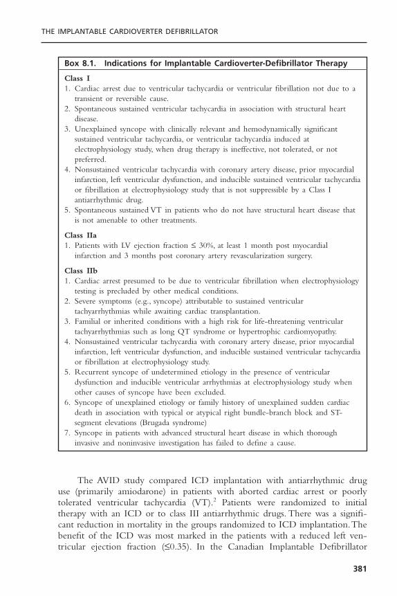
The AVID study compared ICD implantation with antiarrhythmic druguse (primarily amiodarone) in patients with aborted cardiac arrest or poorly tolerated ventricular tachycardia (VT).2 Patients were randomized to initialtherapy with an ICD or to class III antiarrhythmic drugs. There was a signifi-cant reduction in mortality in the groups randomized to ICD implantation.Thebenefit of the ICD was most marked in the patients with a reduced left ven-tricular ejection fraction (£0.35). In the Canadian Implantable Defibrillator
THE IMPLANTABLE CARDIOVERTER DEFIBRILLATOR
381
Box 8.1. Indications for Implantable Cardioverter-Defibrillator Therapy
Class I1. Cardiac arrest due to ventricular tachycardia or ventricular fibrillation not due to a
transient or reversible cause.2. Spontaneous sustained ventricular tachycardia in association with structural heart
disease.3. Unexplained syncope with clinically relevant and hemodynamically significant
sustained ventricular tachycardia, or ventricular tachycardia induced atelectrophysiology study, when drug therapy is ineffective, not tolerated, or notpreferred.
4. Nonsustained ventricular tachycardia with coronary artery disease, prior myocardialinfarction, left ventricular dysfunction, and inducible sustained ventricular tachycardiaor fibrillation at electrophysiology study that is not suppressible by a Class Iantiarrhythmic drug.
5. Spontaneous sustained VT in patients who do not have structural heart disease thatis not amenable to other treatments.
Class IIa1. Patients with LV ejection fraction £ 30%, at least 1 month post myocardial
infarction and 3 months post coronary artery revascularization surgery.
Class IIb1. Cardiac arrest presumed to be due to ventricular fibrillation when electrophysiology
testing is precluded by other medical conditions.2. Severe symptoms (e.g., syncope) attributable to sustained ventricular
tachyarrhythmias while awaiting cardiac transplantation.3. Familial or inherited conditions with a high risk for life-threatening ventricular
tachyarrhythmias such as long QT syndrome or hypertrophic cardiomyopathy.4. Nonsustained ventricular tachycardia with coronary artery disease, prior myocardial
infarction, left ventricular dysfunction, and inducible sustained ventricular tachycardiaor fibrillation at electrophysiology study.
5. Recurrent syncope of undetermined etiology in the presence of ventriculardysfunction and inducible ventricular arrhythmias at electrophysiology study whenother causes of syncope have been excluded.
6. Syncope of unexplained etiology or family history of unexplained sudden cardiacdeath in association with typical or atypical right bundle-branch block and ST-segment elevations (Brugada syndrome)
7. Syncope in patients with advanced structural heart disease in which thoroughinvasive and noninvasive investigation has failed to define a cause.

Study (CIDS), 659 patients with ventricular tachycardia, ventricular fibrillation,or syncope were randomized to antiarrhythmic therapy with amiodarone orICD implantation. A 20% reduction in mortality was observed in the ICDgroup, although it did not reach statistical significance.3 However, subsequentanalyses showed that a left ventricular ejection fraction less than 0.35, age over70 years, and advanced congestive heart failure were characteristics of thepatients who were most likely to benefit from ICD implantation.4 In the CASHstudy, 288 patients with a history of cardiac arrest were randomized to receivemetoprolol, amiodarone, propafenone, or to undergo ICD implantation. Therewas an increased mortality in the group treated with propafenone, and a 28%decreased mortality at the 4-year follow-up evaluation in the patients whoreceived ICDs.5 These studies established the benefit of ICD therapy as first-line treatment among patients with a history of life-threatening arrhythmias (i.e.,secondary prevention), particularly in individuals with left ventricular dysfunc-tion; thus, antiarrhythmic drugs have been relegated to adjunctive therapy toreduce arrhythmia recurrence rates. The AVID II study will address the issuedirectly of the role of ICD therapy for secondary prevention among patientswith preserved left ventricular systolic function.
Once the relative safety of ICD implantation became apparent, the use ofthis therapy for primary prevention of sudden death was studied. The MADITand MUSTT trials evaluated patients with coronary artery disease, left ventric-ular systolic dysfunction, nonsustained ventricular tachycardia, and inducible sus-tained monomorphic ventricular tachycardia. In the MADIT study, patients wererandomized to either receive an ICD or “conventional” medical therapy, whichwas most commonly amiodarone.6 In the MUSTT study, patients were ran-domized to either no antiarrhythmic therapy or electrophysiologically guideddrug therapy. In 46% of the latter group, ICD implantation was performedbecause of the failure of antiarrhythmic drugs to suppress inducible arrhyth-mias.7 Despite these differences in study design, the results of the two trials wereremarkably similar; ICD use decreased mortality more than 50% in these cohortswith ischemic cardiomyopathy.8
It is interesting that the magnitude of mortality reduction in these primaryprevention trials appears even larger than in the studies of patients with a historyof aborted cardiac arrest or sustained ventricular tachycardia. One possible expla-nation for this apparent paradox is that the groups who were evaluated inprimary prevention studies had lower mean ejection fractions and higher inci-dences of congestive heart failure, two potent predictors of mortality.
Expanding the indications for ICD use is an area of intense investigation.The analysis of the MUSTT registry of patients with coronary artery disease,reduced ejection fraction, and no inducible sustained ventricular tachycardiademonstrated a disturbingly high mortality rate, even though it was significantlylower than that among patients with inducible ventricular tachycardia.9 Thisindicates that methods of risk stratification, other than by electrophysiologytesting, are necessary. The MADIT II study was a prospective randomized trialof 1232 subjects with previous myocardial infarction and ejection fraction of
CARDIAC PACING AND ICDS
382
0.30 or less.10 Spontaneous nonsustained VT or electrophysiology testing werenot required for enrollment in this trial.The ICD and control groups had similarclinical characteristics with a mean age of approximately 65 years, 67% withcongestive heart failure (NYHA II–IV) and mean left ventricular ejection frac-tion of 0.23. In addition, beta blocker and angiotensin converting-enzymeinhibitor use was approximately 70% among each group. During a mean follow-up of 20 months, the mortality rates were 14.2% in the ICD group and 19.8%in the control group (Hazard ratio 0.69, 95% confidence interval, 0.51–0.93, P= .016). In a controversial decision, reimbursement for ICD implantation amongMedicare patients was approved only for those patients who met MADIT IIcriteria and had intraventricular conduction delay, as evidenced by a QRS dura-tion of 120 milliseconds or greater.
Several other primary prevention studies evaluated patients with a reducedleft ventricular ejection fraction without requiring the presence of coronaryartery disease. The SCD HeFT study evaluated more than 2500 subjects withcongestive heart failure (NYHA II and III) and left ventricular systolic dys-function (ejection fraction £ 35%), irrespective of etiology (i.e., ischemic or non-ischemic cardiomyopathies). ICD implantation, but not amiodarone, was shownto reduce all-cause mortality. Similar mortality reductions were observed amongthe subgroups with ischemic and nonischemic cardiomyopathies. The DEFI-NITE study randomized 458 subjects with dilated, nonischemic cardiomyopa-thy and frequent ventricular ectopy to receive an ICD or optimal medicaltherapy. There was a strong trend toward a mortality reduction in the ICDcohort, and a significant reduction in the incidence of sudden cardiac deaths (P = .006).11
Not all high-risk groups benefit from ICD implantation, as shown by theCABG Patch trial. In this study, patients with ischemic cardiomyopathy and anabnormal signal-averaged electrocardiogram were randomized to receive an ICDor no antiarrhythmic treatment at the time of coronary artery bypass surgery.No effect on mortality was observed with ICD use in this cohort.12 TheDINAMIT study evaluated patients with acute myocardial infarction, left ven-tricular systolic dysfunction and reduced heart rate variability. No mortalitybenefit was observed with ICD implantation.The reasons for the failure of thesestudies to show a benefit of ICD therapy are unclear. The use of noninvasiverisk modifiers, such as signal-averaged ECG or heart rate variability, may beinsufficient to identify a high-risk cohort. Also, the competing mortality risksearly post-MI or post bypass surgery may offset any benefit of ICD therapy.However, these studies clearly demonstrate that clinical trials and not “commonsense” needs to guide the decision to implant devices.
One cohort that is particularly difficult to manage is those patients withstructural heart disease and a history of syncope. These patients have beenexcluded from most prospective, randomized studies because, on one hand, theydo not have documented arrhythmias to be included in secondary preventionstudies, and, on the other hand, they cannot be classified as asymptomatic to beincluded in primary prevention trials. Present guidelines recommend ICD
THE IMPLANTABLE CARDIOVERTER DEFIBRILLATOR
383

implantation in patients with inducible ventricular tachycardia and syncope (seeBox 8.1). However, initial treatment with an ICD in patients with syncope anddilated cardiomyopathy, regardless of the results of electrophysiology testing, israpidly becoming standard clinical practice,13,14 despite the lack of randomizedstudies to support this strategy. The retrospective analyses that have been per-formed consistently indicate high rates of appropriate ICD therapy in this population, comparable to patients with documented sustained ventriculararrhythmias. Many of these patients now meet other indications for ICDimplantation (e.g., MADIT II or SCD HeFT), so their management is less con-troversial. Patients with primary electrical disease, such as the Brugada syndromeand long QT syndrome, are another cohort in whom ICD use is becomingmore common, particularly in those patients with a history of syncope or ven-tricular arrhythmias.15
PULSE GENERATORS AND LEAD SYSTEMSEarly ICD pulse generators were large and bulky. The size (115 to 145cm3) andweight (195 to 235g) of these devices mandated abdominal implantation, typ-ically in the left upper quadrant either subcutaneously or most often under therectus muscle. The surgical procedure for abdominal ICD implantation is moreextensive than for endocardial pacemakers, in part because it requires tunnelingleads from the chest. The abdominal location of the pulse generator and thesurgical procedure required were likely responsible for the higher complicationrates observed with early ICD implantation, particularly infection and lead frac-tures.
Modern pulse generator size has decreased significantly. With the down-sizing of these devices (30 to 39cm3, 70 to 84g), routine subcutaneous pectoralimplantation is possible,16 although these pulse generators are still significantlylarger than pacemakers. This implantation approach is not associated with anyincreased risk of complications.17 Despite the large size of the early pulse gen-erators, their battery life was only approximately 2 years. With improvement inbattery design and reduction of monitoring current drain, the expected life spanof many ICD pulse generators is now more than 6 years. This has obvious andimportant implications for the cost effectiveness of this therapy.18
Modern ICD pulse generators have very sophisticated programmability andinternal circuitry. All pulse generators have noninvasive pacing induction, withthe capabilities for programmed ventricular stimulation. With real-time teleme-try of intracardiac electrograms, the pacing, shocking impedances, and pacingthresholds of the ICD lead systems can be monitored noninvasively as well, toaid in the assessment of lead function. Detailed data logging is present, includ-ing precise measurements of arrhythmia rates, time of occurrence, and responseto therapy. In addition, stored electrograms provide a recording of the arrhyth-mia at the time of device activity. This is most useful in assessing the appropri-ateness of therapy (i.e., shocks for atrial fibrillation versus ventricular tachycardia)and any malfunctions of the system. Finally, the capacitors in the pulse genera-
CARDIAC PACING AND ICDS
384
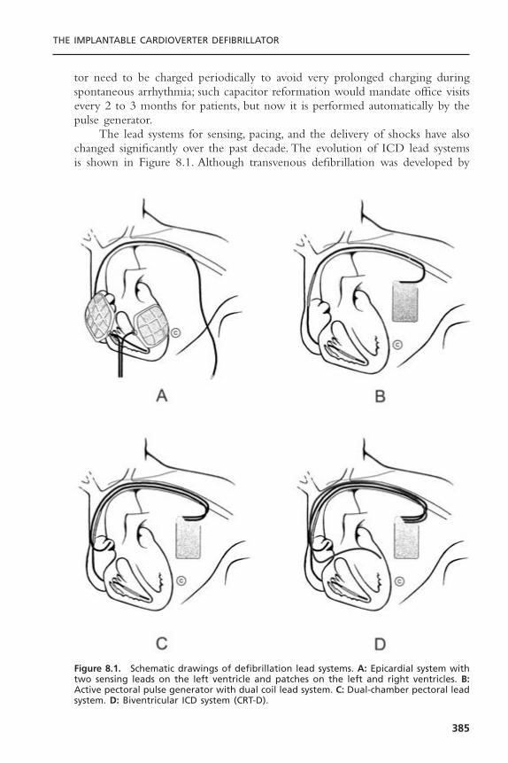
tor need to be charged periodically to avoid very prolonged charging duringspontaneous arrhythmia; such capacitor reformation would mandate office visitsevery 2 to 3 months for patients, but now it is performed automatically by thepulse generator.
The lead systems for sensing, pacing, and the delivery of shocks have alsochanged significantly over the past decade. The evolution of ICD lead systemsis shown in Figure 8.1. Although transvenous defibrillation was developed by
THE IMPLANTABLE CARDIOVERTER DEFIBRILLATOR
385
Figure 8.1. Schematic drawings of defibrillation lead systems. A: Epicardial system withtwo sensing leads on the left ventricle and patches on the left and right ventricles. B:Active pectoral pulse generator with dual coil lead system. C: Dual-chamber pectoral leadsystem. D: Biventricular ICD system (CRT-D).

Mirowski in his pioneering studies of the ICD,19 the initial commercial systemsused epicardial sensing leads and patches placed on the heart. Subsequently, thedevelopment of integrated leads incorporating both rate-sensing electrodes anddefibrillation coils that led to the routine use of nonthoracotomy lead systems.The pectoral placement of pulse generators allowed further improvement in leadtechnology, because the pulse generator shell can serve as an extrathoracic elec-trode and actually become part of the lead system. These active pulse genera-tor systems further simplify the implantation procedure while enhancingdefibrillation efficacy.20
ICD leads can be coaxial or multilumen, with insulation of silicone,polyurethane, or fluoropolymers. Both single-coil and dual-coil defibrillationleads are available, with active or passive fixation. Coaxial lead design was dom-inant until the mid-1990s. This is characterized by a coiled conductor with anoutside insulation layer, both surrounded by another conductor.Typically the tipconductor would be central with the ring conductor and then the defibrilla-tion conductor more peripheral. Multilumen leads are preferred today, with con-ductors running in parallel through a single insulating lead body.The advantagesof this design include greater space efficiency resulting in smaller leads, andgreater resistance to compressive forces by including extra lumens within thelead body.
Lead insulation can have an important impact on long-term stability andfunction. Silicone is inert, biostable, and biocompatible, but has a high coeffi-cient friction. It is soft, making it prone to damage during implantation and canswell over time. Polyurethane is biocompatible, has a high tensile strengthmaking small lead diameters possible, and a low coefficient of friction, but isprone to environmental stress cracking and metal ion oxidation. Recent reportshighlight the high failure rate of polyurethane leads,21 so they should be avoidedgiven the superiority of alternative insulators. Fluoropolymers (e.g., PTFE andETFE) are the most biocompatible, have high tensile strength allowing smalllead size, but are stiff, susceptible to damage from traction when the leadmigrates, and they are prone to insulation micro defects and have a difficultmanufacturing process.Today’s lead systems have an insulating body of silicone,and in some instances supplemented by an outside polyurethane layer (not usedfor insulation) to reduce friction, abrasion, and scar formation. Metal ion oxi-dation is avoided as polyurethane is not in direct contact with the conductors.The conductors are often insulated with an extra thin layer of fluoropolymer.
Dual-chamber ICDs are now used more frequently than single chamberdevices. For dual-chamber systems, a separate atrial lead is used. These are typ-ically simple bipolar pacemaker leads, with no unique design for being part ofan ICD. Radiographs of a dual-chamber lead system, including a dual-coil inte-grated defibrillation lead and an active left pectoral pulse generator, are shownin Figure 8.2. Despite the rapid acceptance of this technology, all of the earlylarge studies establishing ICD indications evaluated only single-chamber systems.The first large study to evaluate directly the impact of dual chamber pacing
CARDIAC PACING AND ICDS
386

among ICD patients was DAVID.22 This was a single blind, randomized trial of506 subjects with standard indications for ICDs. Patients underwent implanta-tion with a dual chamber ICD and were randomized to ventricular backuppacing (VVI at 40bpm) or dual chamber rate responsive pacing (DDDR at 70bpm). Surprisingly, dual-chamber pacing was associated with worse clinical out-comes. The 1-year survival free of the primary endpoint of mortality or CHFhospitalization was 83.9% for patients randomized to VVI pacing and 73.3% forthose patients randomized to DDDR pacing (Hazard ratio 1.61, P £ .03). Theresults of this study have challenged the approach of indiscriminate use of dualchamber pacing among ICD patients.
IMPLANTABLE CARDIOVERTER-DEFIBRILLATOR IMPLANTATIONICD systems are implanted by electrophysiologists in nearly 90% of patients,often without the use of an operating room or general anesthesia.23 The down-sizing of ICD pulse generators allowing for routine pectoral implantation simplified the operative procedure and costs,24 so that the implantation tech-nique now approaches that of a permanent pacemaker; however, the acutetesting and management of these devices still requires electrophysiology expertise. It is for this reason that current guidelines require the presence of anelectrophysiologist for the implantation procedure.25
Whether implanted in an operating room, a multipurpose procedure room,or an electrophysiology laboratory, and whether general anesthesia or conscious
THE IMPLANTABLE CARDIOVERTER DEFIBRILLATOR
387
Figure 8.2. Radiographs of a dual-chamber ICD lead system. Left: Posterior-anterior view.Right: Lateral view. Note the integrated, dual-coil lead with the tip in right ventricularapex. There is a separate right atrial bipolar pacing lead and a left pectoral pulse gen-erator.
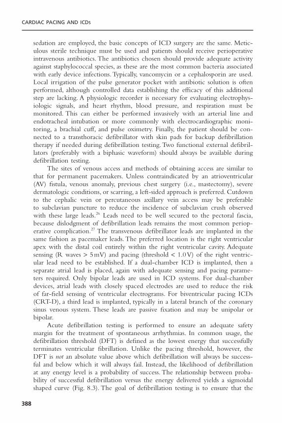
sedation are employed, the basic concepts of ICD surgery are the same. Metic-ulous sterile technique must be used and patients should receive perioperativeintravenous antibiotics. The antibiotics chosen should provide adequate activityagainst staphylococcal species, as these are the most common bacteria associatedwith early device infections. Typically, vancomycin or a cephalosporin are used.Local irrigation of the pulse generator pocket with antibiotic solution is oftenperformed, although controlled data establishing the efficacy of this additionalstep are lacking. A physiologic recorder is necessary for evaluating electrophys-iologic signals, and heart rhythm, blood pressure, and respiration must be monitored. This can either be performed invasively with an arterial line andendotracheal intubation or more commonly with electrocardiographic moni-toring, a brachial cuff, and pulse oximetry. Finally, the patient should be con-nected to a transthoracic defibrillator with skin pads for backup defibrillationtherapy if needed during defibrillation testing.Two functional external defibril-lators (preferably with a biphasic waveform) should always be available duringdefibrillation testing.
The sites of venous access and methods of obtaining access are similar tothat for permanent pacemakers. Unless contraindicated by an atrioventricular(AV) fistula, venous anomaly, previous chest surgery (i.e., mastectomy), severedermatologic conditions, or scarring, a left-sided approach is preferred. Cutdownto the cephalic vein or percutaneous axillary vein access may be preferable to subclavian puncture to reduce the incidence of subclavian crush observedwith these large leads.26 Leads need to be well secured to the pectoral fascia,because dislodgment of defibrillation leads remains the most common periop-erative complication.27 The transvenous defibrillator leads are implanted in thesame fashion as pacemaker leads. The preferred location is the right ventricularapex with the distal coil entirely within the right ventricular cavity. Adequatesensing (R waves > 5mV) and pacing (threshold < 1.0V) of the right ventric-ular lead need to be established. If a dual-chamber ICD is implanted, then aseparate atrial lead is placed, again with adequate sensing and pacing parame-ters required. Only bipolar leads are used in ICD systems. For dual-chamberdevices, atrial leads with closely spaced electrodes are used to reduce the riskof far-field sensing of ventricular electrograms. For biventricular pacing ICDs(CRT-D), a third lead is implanted, typically in a lateral branch of the coronarysinus venous system. These leads are passive fixation and may be unipolar orbipolar.
Acute defibrillation testing is performed to ensure an adequate safetymargin for the treatment of spontaneous arrhythmias. In common usage, thedefibrillation threshold (DFT) is defined as the lowest energy that successfullyterminates ventricular fibrillation. Unlike the pacing threshold, however, theDFT is not an absolute value above which defibrillation will always be success-ful and below which it will always fail. Instead, the likelihood of defibrillationat any energy level is a probability of success. The relationship between proba-bility of successful defibrillation versus the energy delivered yields a sigmoidalshaped curve (Fig. 8.3). The goal of defibrillation testing is to ensure that the
CARDIAC PACING AND ICDS
388
THE IMPLANTABLE CARDIOVERTER DEFIBRILLATOR
389
maximal energy output of the device has an extremely high (>99%) probabil-ity of terminating ventricular fibrillation in a given patient. There are differentmethods to determine the DFT, and each method provides a value with different significance.
The DFT value derived from each testing method establishes different posi-tions on the defibrillation success curve for a given patient. For example, a singletermination of fibrillation with a given energy level (DFT, Table 8.1) identifiesan energy that may terminate fibrillation in as few as 25% of repeated attemptsdue to the probabilistic nature of defibrillation. By demonstrating that this sameshock energy terminates ventricular fibrillation three times without failure;however, it may be concluded that that energy level is high on the probabilitycurve for success and in fact has at least a 75% chance of terminating fibrilla-tion on further attempts.28
Understanding precisely what a given DFT value represents allows thephysician to program an appropriate safety margin of energy output above theDFT to ensure termination of all ventricular fibrillation episodes. In practice,the simple convention of programming output to 10 J greater than the DFT iswidely accepted and usually provides reliable defibrillation.This method is expe-dient at implant; but through careful DFT testing, lesser energy margins may besatisfactory as well29 (Table 8.1).
There are many testing algorithms to assess defibrillation efficacy and deter-mine a value for DFT (Fig. 8.4), but two methods predominate: the single-energy success and step-down protocols. For both methods, the first shock istypically set at least 10 J less than the maximal output of the device.Ventricu-lar fibrillation is induced by pacing through the right ventricular electrode orwith a low-energy shock on the T wave. The pulse generator will then auto-matically sense the arrhythmia, charge, and deliver a shock. If the first shock issuccessful, then this energy level can be repeated once or twice more (single-energy success method). This technique allows for minimal testing to establishadequate acute defibrillation efficacy. Alternatively, in the “step-down method”the shock energy is decreased on each trial until a shock energy is reached thatfails to defibrillate. The lowest energy level to successfully defibrillate is theDFT.28 This energy level may be tested an additional one or two times if desiredto further ensure the likelihood of success. Other algorithms that can be usedto determine DFT are the binary search method, in which shock energy isdecreased or increased depending on the results of the preceding defibrillationtrial,30 or the Bayesian search method (Fig. 8.4).When ICD shocks fail, a high-output internal or transthoracic shock should be given immediately for arrhyth-mia termination.There is increasing interest in minimizing defibrillation testing.Consequently, the practice of testing only one episode of ventricular fibrillationand then programming devices to maximum output is gaining in popularity.This strategy probably works because of the very high efficacy of modern leadsystem and shock waveforms.31 There is even a growing practice of performingno defibrillation testing at the time of implantation, although the prospectivedata to support this strategy are lacking.

CARDIAC PACING AND ICDS
390
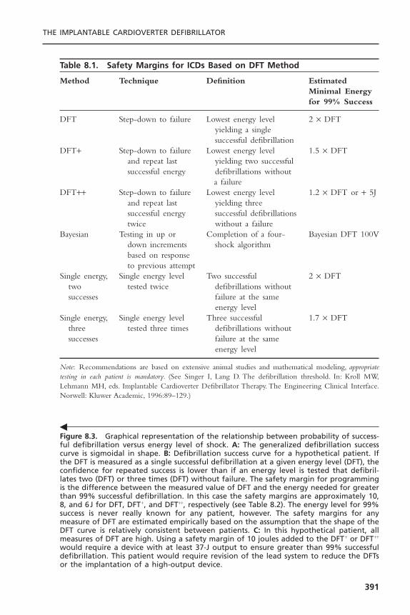
THE IMPLANTABLE CARDIOVERTER DEFIBRILLATOR
391
Figure 8.3. Graphical representation of the relationship between probability of success-ful defibrillation versus energy level of shock. A: The generalized defibrillation successcurve is sigmoidal in shape. B: Defibrillation success curve for a hypothetical patient. Ifthe DFT is measured as a single successful defibrillation at a given energy level (DFT), theconfidence for repeated success is lower than if an energy level is tested that defibril-lates two (DFT) or three times (DFT) without failure. The safety margin for programmingis the difference between the measured value of DFT and the energy needed for greaterthan 99% successful defibrillation. In this case the safety margins are approximately 10,8, and 6J for DFT, DFT +, and DFT++, respectively (see Table 8.2). The energy level for 99%success is never really known for any patient, however. The safety margins for anymeasure of DFT are estimated empirically based on the assumption that the shape of theDFT curve is relatively consistent between patients. C: In this hypothetical patient, allmeasures of DFT are high. Using a safety margin of 10 joules added to the DFT + or DFT++
would require a device with at least 37-J output to ensure greater than 99% successfuldefibrillation. This patient would require revision of the lead system to reduce the DFTsor the implantation of a high-output device.
�
Table 8.1. Safety Margins for ICDs Based on DFT Method
Method Technique Definition Estimated Minimal Energyfor 99% Success
DFT Step-down to failure Lowest energy level 2 ¥ DFTyielding a single successful defibrillation
DFT+ Step-down to failure Lowest energy level 1.5 ¥ DFTand repeat last yielding two successfulsuccessful energy defibrillations without
a failureDFT++ Step-down to failure Lowest energy level 1.2 ¥ DFT or + 5J
and repeat last yielding three successful energy successful defibrillations twice without a failure
Bayesian Testing in up or Completion of a four- Bayesian DFT 100Vdown increments shock algorithmbased on response to previous attempt
Single energy, Single energy level Two successful 2 ¥ DFTtwo tested twice defibrillations withoutsuccesses failure at the same
energy levelSingle energy, Single energy level Three successful 1.7 ¥ DFT
three tested three times defibrillations without successes failure at the same
energy level
Note: Recommendations are based on extensive animal studies and mathematical modeling, appropriatetesting in each patient is mandatory. (See Singer I, Lang D. The defibrillation threshold. In: Kroll MW,Lehmann MH, eds. Implantable Cardioverter Defibrillator Therapy. The Engineering Clinical Interface.Norwell: Kluwer Academic, 1996:89–129.)
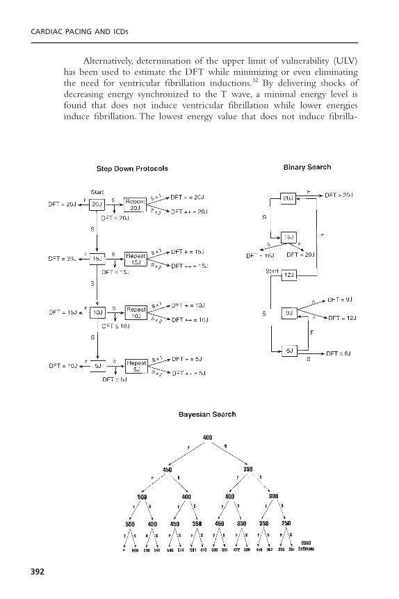
CARDIAC PACING AND ICDS
392
Alternatively, determination of the upper limit of vulnerability (ULV)has been used to estimate the DFT while minimizing or even eliminatingthe need for ventricular fibrillation inductions.32 By delivering shocks ofdecreasing energy synchronized to the T wave, a minimal energy level isfound that does not induce ventricular fibrillation while lower energiesinduce fibrillation. The lowest energy value that does not induce fibrilla-
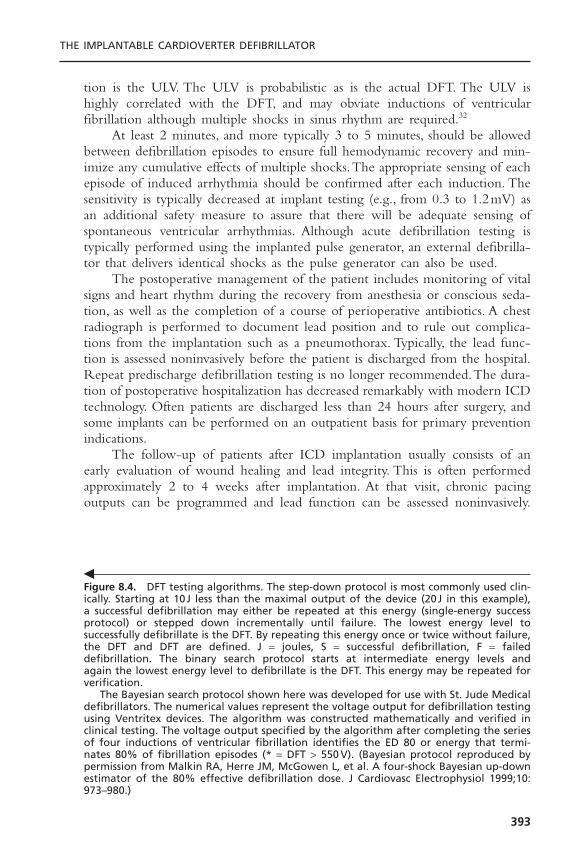
tion is the ULV. The ULV is probabilistic as is the actual DFT. The ULV ishighly correlated with the DFT, and may obviate inductions of ventricular fibrillation although multiple shocks in sinus rhythm are required.32
At least 2 minutes, and more typically 3 to 5 minutes, should be allowedbetween defibrillation episodes to ensure full hemodynamic recovery and min-imize any cumulative effects of multiple shocks.The appropriate sensing of eachepisode of induced arrhythmia should be confirmed after each induction. Thesensitivity is typically decreased at implant testing (e.g., from 0.3 to 1.2mV) asan additional safety measure to assure that there will be adequate sensing ofspontaneous ventricular arrhythmias. Although acute defibrillation testing is typically performed using the implanted pulse generator, an external defibrilla-tor that delivers identical shocks as the pulse generator can also be used.
The postoperative management of the patient includes monitoring of vitalsigns and heart rhythm during the recovery from anesthesia or conscious seda-tion, as well as the completion of a course of perioperative antibiotics. A chestradiograph is performed to document lead position and to rule out complica-tions from the implantation such as a pneumothorax. Typically, the lead func-tion is assessed noninvasively before the patient is discharged from the hospital.Repeat predischarge defibrillation testing is no longer recommended.The dura-tion of postoperative hospitalization has decreased remarkably with modern ICDtechnology. Often patients are discharged less than 24 hours after surgery, andsome implants can be performed on an outpatient basis for primary preventionindications.
The follow-up of patients after ICD implantation usually consists of anearly evaluation of wound healing and lead integrity. This is often performedapproximately 2 to 4 weeks after implantation. At that visit, chronic pacingoutputs can be programmed and lead function can be assessed noninvasively.
THE IMPLANTABLE CARDIOVERTER DEFIBRILLATOR
393
Figure 8.4. DFT testing algorithms. The step-down protocol is most commonly used clin-ically. Starting at 10J less than the maximal output of the device (20J in this example),a successful defibrillation may either be repeated at this energy (single-energy successprotocol) or stepped down incrementally until failure. The lowest energy level to successfully defibrillate is the DFT. By repeating this energy once or twice without failure,the DFT and DFT are defined. J = joules, S = successful defibrillation, F = failed defibrillation. The binary search protocol starts at intermediate energy levels and again the lowest energy level to defibrillate is the DFT. This energy may be repeated forverification.
The Bayesian search protocol shown here was developed for use with St. Jude Medicaldefibrillators. The numerical values represent the voltage output for defibrillation testingusing Ventritex devices. The algorithm was constructed mathematically and verified inclinical testing. The voltage output specified by the algorithm after completing the seriesof four inductions of ventricular fibrillation identifies the ED 80 or energy that termi-nates 80% of fibrillation episodes (* = DFT > 550 V). (Bayesian protocol reproduced bypermission from Malkin RA, Herre JM, McGowen L, et al. A four-shock Bayesian up-downestimator of the 80% effective defibrillation dose. J Cardiovasc Electrophysiol 1999;10:973–980.)
�
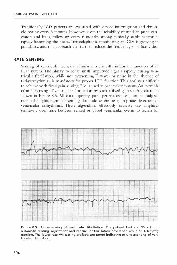
Traditionally ICD patients are evaluated with device interrogation and thresh-old testing every 3 months. However, given the reliability of modern pulse gen-erators and leads, follow-up every 6 months among clinically stable patients israpidly becoming the norm.Transtelephonic monitoring of ICDs is growing inpopularity, and this approach can further reduce the frequency of office visits.
RATE SENSINGSensing of ventricular tachyarrhythmias is a critically important function of anICD system. The ability to sense small amplitude signals rapidly during ven-tricular fibrillation, while not oversensing T waves or noise in the absence oftachyarrhythmias, is mandatory for proper ICD function.This goal was difficultto achieve with fixed gain sensing,33 as is used in pacemaker systems.An exampleof undersensing of ventricular fibrillation by such a fixed gain sensing circuit isshown in Figure 8.5. All contemporary pulse generators use automatic adjust-ment of amplifier gain or sensing threshold to ensure appropriate detection ofventricular arrhythmias. These algorithms effectively increase the amplifier sensitivity over time between sensed or paced ventricular events to search for
CARDIAC PACING AND ICDS
394
Figure 8.5. Undersensing of ventricular fibrillation. The patient had an ICD withoutautomatic sensing adjustment and ventricular fibrillation developed while on telemetrymonitor. The lower rate VVI pacing artifacts are noted indicative of undersensing of ven-tricular fibrillation.

low-amplitude fibrillatory electrograms that may be missed at lower sensitivi-ties. One such algorithm is shown in Figure 8.6. In addition to these sophisti-cated sensing algorithms, the need for stable lead performance is mandatory toensure normal detection of tachyarrhythmias.
Undersensing of ventricular fibrillation was rarely noted with early epi-cardial or bipolar transvenous leads after automatic gain or sensitivity wasemployed. However, with the development of integrated nonthoracotomy leads,undersensing of ventricular tachyarrhythmias was reported.34 These leads initiallyused extended bipolar sensing, in which the right ventricular coil serves bothfor sensing and as an electrode for high-energy shocks. Undersensing was mostcommonly observed with the redetection of ventricular fibrillation followingfailed shocks. The most likely mechanism of this phenomenon is stunning oflocal myocardium following shocks, resulting in the diminution of the electro-gram near the tip of the lead. With positioning of the right ventricular shock-ing coil farther from the rate sensing electrode tip, post-shock undersensing isminimized.35 Data from large clinical trials of integrated transvenous leads havedemonstrated excellent detection of ventricular tachycardia and fibrillation, indi-cating that clinically important undersensing is very rare.36 However, the optimalspacing between the lead tip and the right ventricular shocking coil is unknown.As the coil is moved farther from the tip, and thus farther from the myocardium,local stunning is reduced but defibrillation thresholds increase. At present, bothtrue bipolar sensing, with a dedicated tip and ring, and integrated sensing, wherethe distal coil is used for both sensing and shocks, are available.
Another area of potential difficulty with sensing occurs when ICDs areused in conjunction with separate pacemakers. The proximity of the endocar-dial pacemaker and ICD leads within the ventricle can lead to several problems,including double counting during pacing, which can cause inappropriate shocks,
THE IMPLANTABLE CARDIOVERTER DEFIBRILLATOR
395
Figure 8.6. A schematic representation of automatic sensitivity during sinus rhythm andventricular fibrillation. In sinus rhythm, sensitivity increases slowly to avoid oversensingT waves. However, with the onset of ventricular fibrillation, high sensitivity is maintainedto minimize undersensing. (Reproduced with permission from Medtronic Inc., Minneapolis, MN.)

and sensing of pacemaker pulses during ventricular fibrillation, which can inhibittherapy. The problems of pacemaker–ICD interactions are largely of historicalinterest with the development of dual-chamber, rate-responsive ICD systems.Such systems provide all of the basic capabilities of permanent pacemakers, obvi-ating implanting or retaining separate devices.
Although undersensing of ventricular tachyarrhythmias is very unusual withmodern lead systems and pulse generators, oversensing of other biologic signalsis now more common.37 The maximum sensitivity of pulse generators isincreased (up to 0.15mV) with contemporary low noise amplifiers. At maximalsensitivity, myopotentials arising from the diaphragm or pectoral muscles cancause inappropriate ICD discharges.This problem is more likely to occur duringperiods of ventricular pacing, when the amplifier sensitivity is maximized. Oftena history of coughing or straining preceding ICD discharges can be elicited fromthe patient, suggesting that myopotential oversensing is present. Such oversensingcan be confirmed by monitoring ventricular electrograms during provocativemaneuvers such as handgrip, Valsalva, or deep inspiration. Several strategies have been used to prevent further ICD oversensing, including decreasing themaximum sensitivity of the pulse generator, decreasing the bradycardic pacingrate, or increasing the AV delay to minimize ventricular pacing, prolonging thedetection intervals to prevent shocks from transient oversensing, and implantinga separate rate sensing lead in the right ventricular outflow tract more distantfrom the diaphragmatic surface.38 Oversensing of T-waves with double count-ing is another problem observed more frequently with modern pulse genera-tors because of increased maximum sensitivity and aggressive sensing algorithms.Again, this can often be avoided with device reprogramming including reduc-ing the maximum sensitivity, prolonging the refractory period or reducing theaggressiveness of the autosensitivity algorithm.
Extensive data logging capabilities are present in pulse generators. Allsystems provide beat-to-beat interval data for detected tachyarrhythmias.This ishelpful for identifying the arrhythmias associated with shocks. For instance, veryirregular intervals are suggestive of atrial fibrillation, whereas the sudden onsetof a regular tachycardia is indicative of either monomorphic ventricular tachy-cardia or paroxysmal supraventricular tachycardia. A very rapid rhythm withnonphysiologic intervals (<130msec) is indicative of a sensing malfunction,typically due to either a lead insulation defect or a loose set-screw in the pulsegenerator header.39
A further diagnostic tool in devices is stored electrograms.This significantlyimproves the physician’s ability to interpret the appropriateness of defibrillationshocks.40 The electrodes used to record the electrogram may or may not be thesame electrodes used for the detection of arrhythmias. “Near-field” electrogramsare recordings of the local bipolar ventricular electrogram, which is also usedfor arrhythmia detection.This can either be a true bipolar sensing, with record-ing from the electrode tip to a more proximal ring, or extended bipolar sensingfrom the tip to a right ventricular shocking coil. For “far-field” electrograms,recordings are made between shocking electrodes, which for a typical transve-
CARDIAC PACING AND ICDS
396
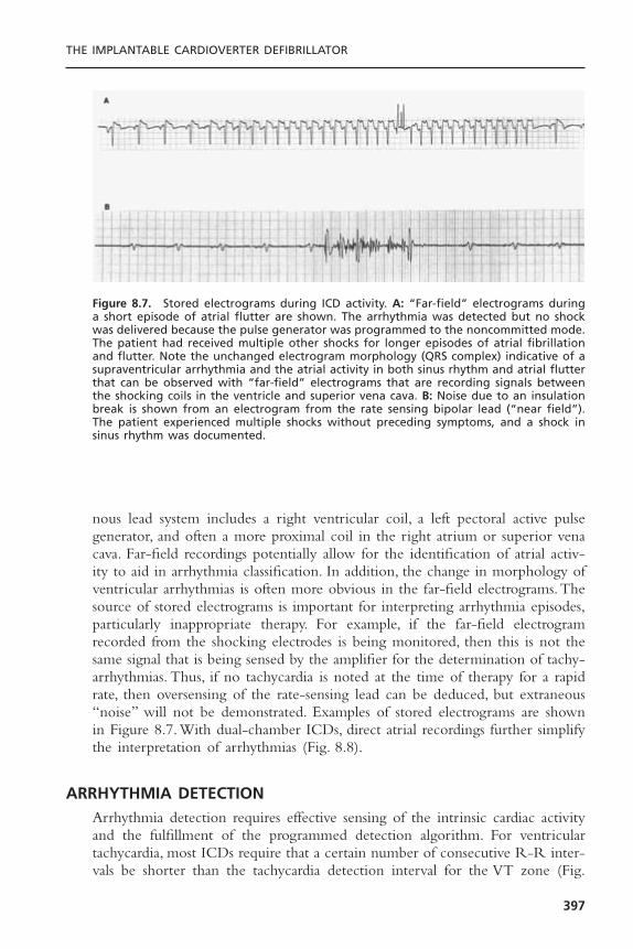
nous lead system includes a right ventricular coil, a left pectoral active pulsegenerator, and often a more proximal coil in the right atrium or superior venacava. Far-field recordings potentially allow for the identification of atrial activ-ity to aid in arrhythmia classification. In addition, the change in morphology ofventricular arrhythmias is often more obvious in the far-field electrograms.Thesource of stored electrograms is important for interpreting arrhythmia episodes,particularly inappropriate therapy. For example, if the far-field electrogramrecorded from the shocking electrodes is being monitored, then this is not thesame signal that is being sensed by the amplifier for the determination of tachy-arrhythmias. Thus, if no tachycardia is noted at the time of therapy for a rapidrate, then oversensing of the rate-sensing lead can be deduced, but extraneous“noise” will not be demonstrated. Examples of stored electrograms are shownin Figure 8.7.With dual-chamber ICDs, direct atrial recordings further simplifythe interpretation of arrhythmias (Fig. 8.8).
ARRHYTHMIA DETECTIONArrhythmia detection requires effective sensing of the intrinsic cardiac activityand the fulfillment of the programmed detection algorithm. For ventriculartachycardia, most ICDs require that a certain number of consecutive R-R inter-vals be shorter than the tachycardia detection interval for the VT zone (Fig.
THE IMPLANTABLE CARDIOVERTER DEFIBRILLATOR
397
Figure 8.7. Stored electrograms during ICD activity. A: “Far-field” electrograms duringa short episode of atrial flutter are shown. The arrhythmia was detected but no shockwas delivered because the pulse generator was programmed to the noncommitted mode.The patient had received multiple other shocks for longer episodes of atrial fibrillationand flutter. Note the unchanged electrogram morphology (QRS complex) indicative of asupraventricular arrhythmia and the atrial activity in both sinus rhythm and atrial flutterthat can be observed with “far-field” electrograms that are recording signals betweenthe shocking coils in the ventricle and superior vena cava. B: Noise due to an insulationbreak is shown from an electrogram from the rate sensing bipolar lead (“near field”).The patient experienced multiple shocks without preceding symptoms, and a shock insinus rhythm was documented.

8.9). Because the ventricular fibrillation (VF) electrograms may transiently bevery low in amplitude and undersensed, the ventricular fibrillation detectionalgorithms require that a certain percentage (typically 75%) of R-R intervals ina rolling window of cardiac cycles be shorter than the ventricular fibrillationdetection interval (see Fig. 8.9). After each delivered therapy, the ICD mustdetermine whether the tachycardia was terminated.The redetection criteria aftertherapies are usually somewhat less demanding than the initial detection crite-ria for each zone. The detection criteria in the VT zone may be modified byalgorithms to prevent inappropriate therapy for supraventricular tachycardias.
IMPLANTABLE CARDIOVERTER-DEFIBRILLATOR THERAPIESPacing
All ICD pulse generators have pacing capabilities. This can be simple backupbradycardia support (VVI mode), more physiologic pacing modes with or without rate responsiveness (e.g., DDDR), or high-rate pacing for the ter-mination of ventricular tachycardia or supraventricular tachyarrhythmias (SVTor atrial flutter).Ventricular pacing prevents long pauses that occur spontaneouslyor following shocks for ventricular tachyarrhythmias. Such post-shock pauses can contribute to the hemodynamic compromise associated with these arrhythmias. In fact, in some patients syncopal episodes associated with appro-priate ICD therapy are due to the post-shock pause and not to the primarytachyarrhythmia.
The use of dual-chamber ICD systems has increased dramatically since theywere first approved in 1997. It is estimated that approximately 70% of new ICDsystems (not including biventricular pacing devices) implanted in the UnitedStates are dual-chamber devices.This is a much greater percentage than the 5%to 10% of patients who received both pacemakers and ICDs previously,suggesting that this usage is not due solely to the need for atrial pacing for stan-
CARDIAC PACING AND ICDS
398
Figure 8.8. Stored electrogram from a dual-chamber ICD. The bipolar atrial electrogramis shown on the top panel. Below is the far-field electrogram in the triad configuration(sensing from right ventricle to right atrium and left pectoral pulse generator). Initiallythe patient is in sinus rhythm but ventricular tachycardia with clear AV dissociation develops.Following a burst of antitachycardia pacing (not shown), sinus rhythm is restored on thefar right panel of the electrogram. Note how the atrial electrogram simplifies the inter-pretation of rhythms.
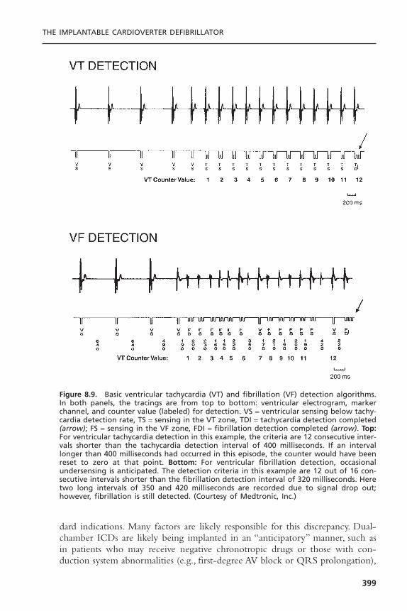
dard indications. Many factors are likely responsible for this discrepancy. Dual-chamber ICDs are likely being implanted in an “anticipatory” manner, such asin patients who may receive negative chronotropic drugs or those with con-duction system abnormalities (e.g., first-degree AV block or QRS prolongation),
THE IMPLANTABLE CARDIOVERTER DEFIBRILLATOR
399
Figure 8.9. Basic ventricular tachycardia (VT) and fibrillation (VF) detection algorithms.In both panels, the tracings are from top to bottom: ventricular electrogram, markerchannel, and counter value (labeled) for detection. VS = ventricular sensing below tachy-cardia detection rate, TS = sensing in the VT zone, TDI = tachycardia detection completed(arrow); FS = sensing in the VF zone, FDI = fibrillation detection completed (arrow). Top:For ventricular tachycardia detection in this example, the criteria are 12 consecutive inter-vals shorter than the tachycardia detection interval of 400 milliseconds. If an intervallonger than 400 milliseconds had occurred in this episode, the counter would have beenreset to zero at that point. Bottom: For ventricular fibrillation detection, occasionalundersensing is anticipated. The detection criteria in this example are 12 out of 16 con-secutive intervals shorter than the fibrillation detection interval of 320 milliseconds. Heretwo long intervals of 350 and 420 milliseconds are recorded due to signal drop out;however, fibrillation is still detected. (Courtesy of Medtronic, Inc.)
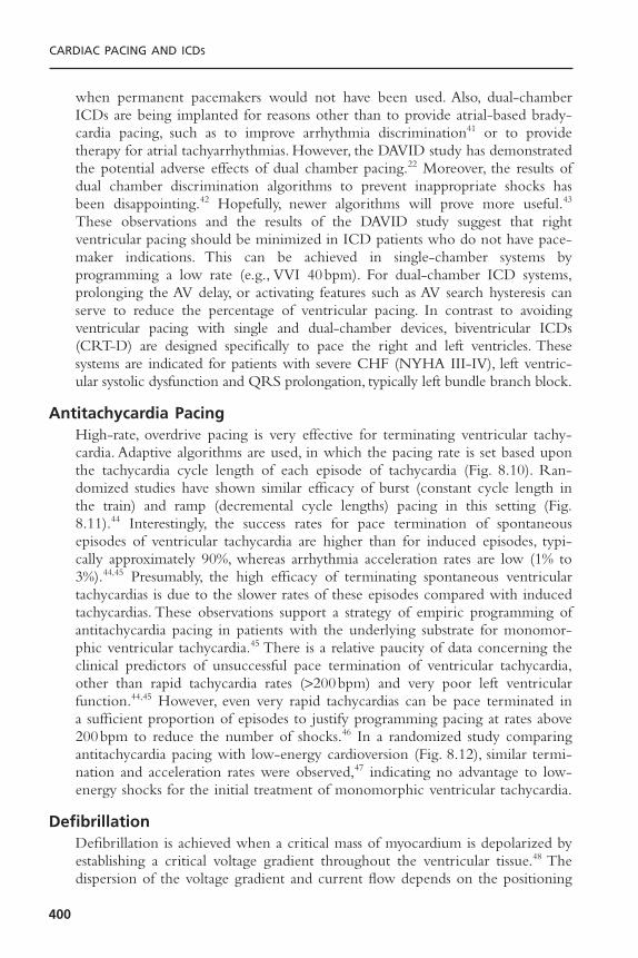
when permanent pacemakers would not have been used. Also, dual-chamberICDs are being implanted for reasons other than to provide atrial-based brady-cardia pacing, such as to improve arrhythmia discrimination41 or to providetherapy for atrial tachyarrhythmias. However, the DAVID study has demonstratedthe potential adverse effects of dual chamber pacing.22 Moreover, the results ofdual chamber discrimination algorithms to prevent inappropriate shocks hasbeen disappointing.42 Hopefully, newer algorithms will prove more useful.43
These observations and the results of the DAVID study suggest that right ventricular pacing should be minimized in ICD patients who do not have pace-maker indications. This can be achieved in single-chamber systems by programming a low rate (e.g., VVI 40bpm). For dual-chamber ICD systems,prolonging the AV delay, or activating features such as AV search hysteresis canserve to reduce the percentage of ventricular pacing. In contrast to avoidingventricular pacing with single and dual-chamber devices, biventricular ICDs(CRT-D) are designed specifically to pace the right and left ventricles. Thesesystems are indicated for patients with severe CHF (NYHA III-IV), left ventric-ular systolic dysfunction and QRS prolongation, typically left bundle branch block.
Antitachycardia PacingHigh-rate, overdrive pacing is very effective for terminating ventricular tachy-cardia. Adaptive algorithms are used, in which the pacing rate is set based uponthe tachycardia cycle length of each episode of tachycardia (Fig. 8.10). Ran-domized studies have shown similar efficacy of burst (constant cycle length inthe train) and ramp (decremental cycle lengths) pacing in this setting (Fig.8.11).44 Interestingly, the success rates for pace termination of spontaneousepisodes of ventricular tachycardia are higher than for induced episodes, typi-cally approximately 90%, whereas arrhythmia acceleration rates are low (1% to3%).44,45 Presumably, the high efficacy of terminating spontaneous ventriculartachycardias is due to the slower rates of these episodes compared with inducedtachycardias. These observations support a strategy of empiric programming ofantitachycardia pacing in patients with the underlying substrate for monomor-phic ventricular tachycardia.45 There is a relative paucity of data concerning theclinical predictors of unsuccessful pace termination of ventricular tachycardia,other than rapid tachycardia rates (>200bpm) and very poor left ventricularfunction.44,45 However, even very rapid tachycardias can be pace terminated ina sufficient proportion of episodes to justify programming pacing at rates above200bpm to reduce the number of shocks.46 In a randomized study comparingantitachycardia pacing with low-energy cardioversion (Fig. 8.12), similar termi-nation and acceleration rates were observed,47 indicating no advantage to low-energy shocks for the initial treatment of monomorphic ventricular tachycardia.
DefibrillationDefibrillation is achieved when a critical mass of myocardium is depolarized byestablishing a critical voltage gradient throughout the ventricular tissue.48 Thedispersion of the voltage gradient and current flow depends on the positioning
CARDIAC PACING AND ICDS
400
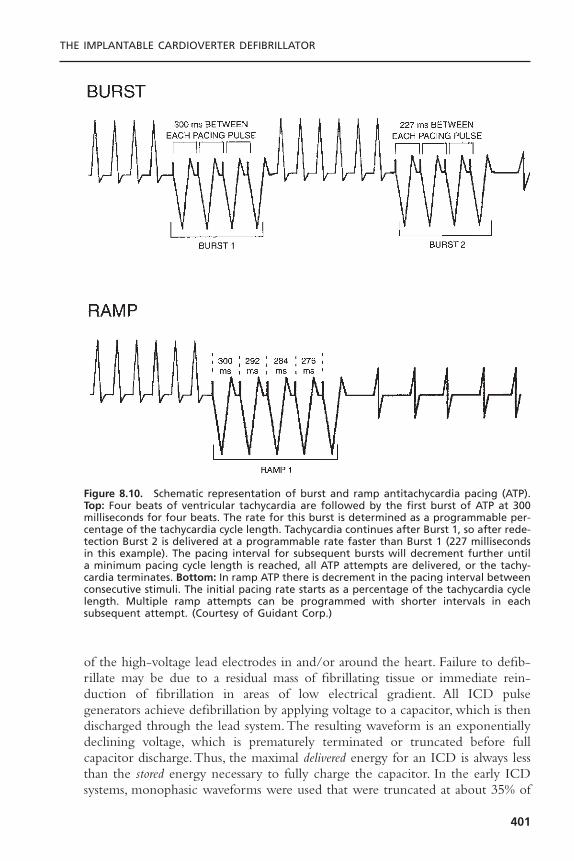
of the high-voltage lead electrodes in and/or around the heart. Failure to defib-rillate may be due to a residual mass of fibrillating tissue or immediate rein-duction of fibrillation in areas of low electrical gradient. All ICD pulsegenerators achieve defibrillation by applying voltage to a capacitor, which is thendischarged through the lead system.The resulting waveform is an exponentiallydeclining voltage, which is prematurely terminated or truncated before fullcapacitor discharge.Thus, the maximal delivered energy for an ICD is always lessthan the stored energy necessary to fully charge the capacitor. In the early ICDsystems, monophasic waveforms were used that were truncated at about 35% of
THE IMPLANTABLE CARDIOVERTER DEFIBRILLATOR
401
Figure 8.10. Schematic representation of burst and ramp antitachycardia pacing (ATP).Top: Four beats of ventricular tachycardia are followed by the first burst of ATP at 300milliseconds for four beats. The rate for this burst is determined as a programmable per-centage of the tachycardia cycle length. Tachycardia continues after Burst 1, so after rede-tection Burst 2 is delivered at a programmable rate faster than Burst 1 (227 millisecondsin this example). The pacing interval for subsequent bursts will decrement further untila minimum pacing cycle length is reached, all ATP attempts are delivered, or the tachy-cardia terminates. Bottom: In ramp ATP there is decrement in the pacing interval betweenconsecutive stimuli. The initial pacing rate starts as a percentage of the tachycardia cyclelength. Multiple ramp attempts can be programmed with shorter intervals in each subsequent attempt. (Courtesy of Guidant Corp.)
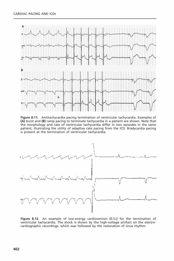
CARDIAC PACING AND ICDS
402
Figure 8.11. Antitachycardia pacing termination of ventricular tachycardia. Examples of(A) burst and (B) ramp pacing to terminate tachycardia in a patient are shown. Note thatthe morphology and rate of ventricular tachycardia differ in two episodes in the samepatient, illustrating the utility of adaptive rate pacing from the ICD. Bradycardia pacingis present at the termination of ventricular tachycardia.
Figure 8.12. An example of low-energy cardioversion (0.5J) for the termination of ventricular tachycardia. The shock is shown by the high-voltage artifact on the electro-cardiographic recordings, which was followed by the restoration of sinus rhythm.
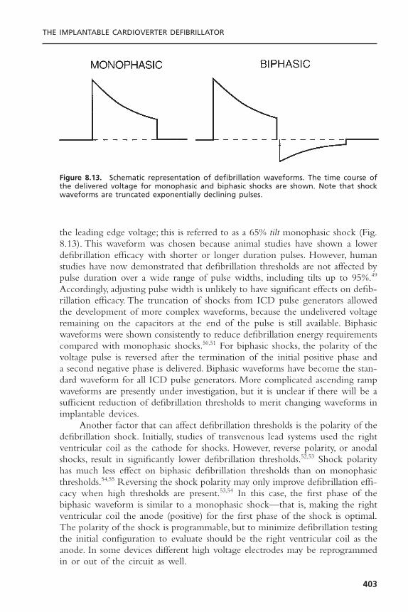
the leading edge voltage; this is referred to as a 65% tilt monophasic shock (Fig.8.13). This waveform was chosen because animal studies have shown a lowerdefibrillation efficacy with shorter or longer duration pulses. However, humanstudies have now demonstrated that defibrillation thresholds are not affected bypulse duration over a wide range of pulse widths, including tilts up to 95%.49
Accordingly, adjusting pulse width is unlikely to have significant effects on defib-rillation efficacy. The truncation of shocks from ICD pulse generators allowedthe development of more complex waveforms, because the undelivered voltageremaining on the capacitors at the end of the pulse is still available. Biphasicwaveforms were shown consistently to reduce defibrillation energy requirementscompared with monophasic shocks.50,51 For biphasic shocks, the polarity of thevoltage pulse is reversed after the termination of the initial positive phase anda second negative phase is delivered. Biphasic waveforms have become the stan-dard waveform for all ICD pulse generators. More complicated ascending rampwaveforms are presently under investigation, but it is unclear if there will be asufficient reduction of defibrillation thresholds to merit changing waveforms inimplantable devices.
Another factor that can affect defibrillation thresholds is the polarity of thedefibrillation shock. Initially, studies of transvenous lead systems used the rightventricular coil as the cathode for shocks. However, reverse polarity, or anodalshocks, result in significantly lower defibrillation thresholds.52,53 Shock polarityhas much less effect on biphasic defibrillation thresholds than on monophasicthresholds.54,55 Reversing the shock polarity may only improve defibrillation effi-cacy when high thresholds are present.53,54 In this case, the first phase of thebiphasic waveform is similar to a monophasic shock—that is, making the rightventricular coil the anode (positive) for the first phase of the shock is optimal.The polarity of the shock is programmable, but to minimize defibrillation testingthe initial configuration to evaluate should be the right ventricular coil as theanode. In some devices different high voltage electrodes may be reprogrammedin or out of the circuit as well.
THE IMPLANTABLE CARDIOVERTER DEFIBRILLATOR
403
Figure 8.13. Schematic representation of defibrillation waveforms. The time course ofthe delivered voltage for monophasic and biphasic shocks are shown. Note that shockwaveforms are truncated exponentially declining pulses.

Capacitance is another factor that may affect defibrillation efficacy. Capac-itors are important components of pulse generator size, so if defibrillation thresh-olds are decreased with lower capacitance, then pulse generator size could bereduced. Decreasing capacitance to 60 or 90mF reduces defibrillation thresholdsmodestly in some studies,56,57 but had no effect on stored energy requirementsand increased peak voltage in other studies.58,59 The defibrillation safety marginis reduced with lower capacitance because of the higher peak voltages required,so the strategy of marked reductions of pulse generator capacitance is unlikelyto be pursued in the future.
Once biphasic waveforms became ubiquitous, the most important advancefor lowering defibrillation thresholds was the development of active pulse generators. With the downsizing of pulse generator size to allow for pectoralplacement, the pulse generator shell can become part of the lead system. Suchactive pulse generators are also known as “hot cans” or “active cans.”The activecan was first evaluated in humans by Bardy and colleagues using a shockingconfiguration from a right ventricular coil to a left pectoral pulse generator.60
This lead system was termed the unipolar configuration because only a singleendocardial electrode is used, analogous to unipolar pacing where the pacemakerpulse generator serves as the return pathway for current from the right ven-tricular electrode.These investigators showed that adequate defibrillation thresh-olds (<20 J) could be achieved in approximately 90% of patients with this simplesingle coil lead system. Subsequently, it was confirmed that defibrillation thresh-olds were lower in the unipolar configuration than in a dual-coil, transvenousconfiguration (where current is delivered between two coils, one in the rightventricle and the other in the superior vena cava).61 Defibrillation thresholds arerelatively insensitive to pulse generator size,62 indicating that defibrillation effi-cacy will not be affected adversely as pulse generators get progressively smaller.
The effect of combining an active pectoral pulse generator with a dual-coil lead was evaluated independent of the development of the unipolar leadconfiguration.This was called the “triad” configuration because of the presenceof three shocking electrodes, the active can and two transvenous coils. In theinitial study of this lead system, it was shown that the mean defibrillation thresh-old decreased 36% compared with a dual-coil shocking vector.63 This benefitwas due more to the lowering of impedance with the active can than to animprovement in the shocking vector. Subsequent studies compared the defi-brillation efficacy of multiple lead configurations.64 Defibrillation thresholds inthe triad lead configuration were again much lower than in the dual-coil transvenous lead configuration, as well as 23% lower than in the single-coilunipolar configuration. In the largest study comparing active can defibrillationconfigurations, the unipolar and triad configurations were measured in 50patients.65 Both the mean and the variability of defibrillation thresholds werelower in the triad configuration. In this study, 98% of patients had a thresholdless than 15 J. Of particular clinical relevance is the reduction of the number ofpatients with high thresholds, because such patients have an inadequate safety
CARDIAC PACING AND ICDS
404
margin and often require complicated implantation procedures to test multiplelead positions or shocking vectors.The uniformly low thresholds with dual-coil,active can lead systems have simplified implantation testing of these systems.
The effect of proximal coil position has also been evaluated.When shock-ing between two coils and no active can, positioning a second lead in the leftsubclavian vein is optimal because it directs current more toward the left sideof the heart compared with a more proximal position in the superior venacava.66 However, no such benefit of the proximal coil position is observed whenan active can is part of the shocking circuit,67 indicating that single-pass dual-coil leads with fixed intercoil spacing should minimize defibrillation thresholdswithout the need for additional leads.This has become the standard lead systemfor implants. Single-coil leads are still used in pediatric patients because com-plications from the proximal coil are more common as a result of continuedgrowth of the child.
The anatomic position of an active pulse generator is important for deter-mining its effect on defibrillation thresholds. In the right pectoral region, thereis no significant change in thresholds with the use of an active can comparedwith a dual-coil transvenous lead.68 This is because an active can increases defib-rillation current requirements due to a worsened shock vector, which is directedaway from the left ventricle and toward the right shoulder. The reduction inimpedance with the active can offsets the increased current resulting in no neteffect on threshold. In the left abdominal position, defibrillation thresholdsdecreased with an active can in one study and were unchanged in anotherstudy.69 In either case, these observations imply that active devices can be usedwhen replacing older abdominal pulse generators.
Despite the marked reduction of defibrillation thresholds with active pectoral pulse generators, there are still some patients with unacceptably highthresholds. Unfortunately, identifying these patients prospectively is difficult.Raitt and colleagues evaluated the clinical predictors of defibrillation efficacy in101 patients with a unipolar defibrillation system.70 The only independent pre-dictors of the biphasic defibrillation threshold were left ventricular mass andresting heart rate. However, all correlations with defibrillation thresholds wereweak. Similarly, no routine clinical factors reliably predict high thresholds in thetriad configuration.71 The possible causes of high DFTs at implant and poten-tial corrective measures are listed in Table 8.2.
Fortunately, the proportion of patients with high defibrillation thresholdsis small with left pectoral active can lead systems. If an adequate safety margincannot be demonstrated at implantation, then further testing is necessary. Thesimplest change is to reverse the polarity of the shocks. Other changes that canbe made include repositioning leads, placing a second coil, implanting a subcu-taneous patch or array,72 or adding a type III antiarrhythmic drug such adofetilide or sotalol which can reduce thresholds. Although most popular ICDshave maximal energy outputs of about 30 J, most manufacturers also producehigh-energy units with delivered energy up to 36 J. These high output devices
THE IMPLANTABLE CARDIOVERTER DEFIBRILLATOR
405
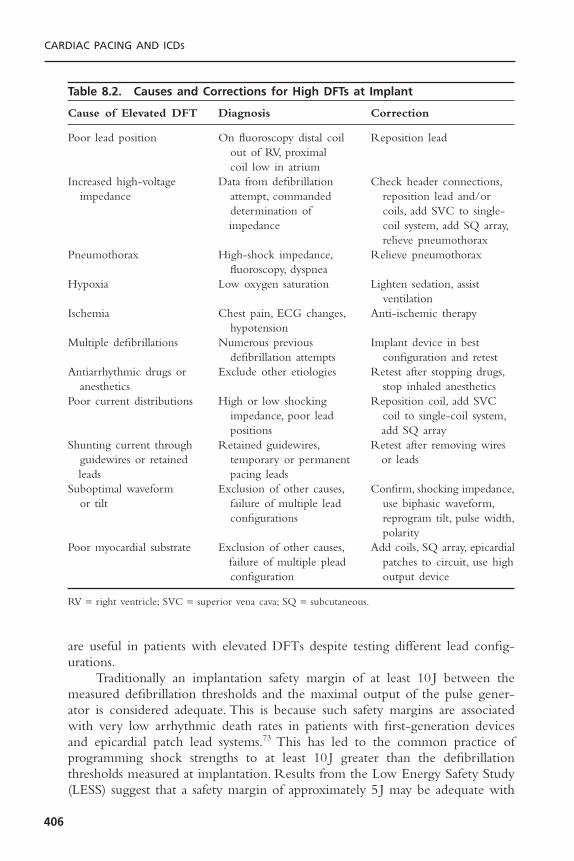
are useful in patients with elevated DFTs despite testing different lead config-urations.
Traditionally an implantation safety margin of at least 10 J between themeasured defibrillation thresholds and the maximal output of the pulse gener-ator is considered adequate. This is because such safety margins are associatedwith very low arrhythmic death rates in patients with first-generation devicesand epicardial patch lead systems.73 This has led to the common practice of programming shock strengths to at least 10 J greater than the defibrillationthresholds measured at implantation. Results from the Low Energy Safety Study(LESS) suggest that a safety margin of approximately 5 J may be adequate with
CARDIAC PACING AND ICDS
406
Table 8.2. Causes and Corrections for High DFTs at Implant
Cause of Elevated DFT Diagnosis Correction
Poor lead position On fluoroscopy distal coil Reposition leadout of RV, proximal coil low in atrium
Increased high-voltage Data from defibrillation Check header connections,impedance attempt, commanded reposition lead and/or
determination of coils, add SVC to single-impedance coil system, add SQ array,
relieve pneumothoraxPneumothorax High-shock impedance, Relieve pneumothorax
fluoroscopy, dyspneaHypoxia Low oxygen saturation Lighten sedation, assist
ventilationIschemia Chest pain, ECG changes, Anti-ischemic therapy
hypotensionMultiple defibrillations Numerous previous Implant device in best
defibrillation attempts configuration and retestAntiarrhythmic drugs or Exclude other etiologies Retest after stopping drugs,
anesthetics stop inhaled anestheticsPoor current distributions High or low shocking Reposition coil, add SVC
impedance, poor lead coil to single-coil system,positions add SQ array
Shunting current through Retained guidewires, Retest after removing wires guidewires or retained temporary or permanent or leadsleads pacing leads
Suboptimal waveform Exclusion of other causes, Confirm, shocking impedance,or tilt failure of multiple lead use biphasic waveform,
configurations reprogram tilt, pulse width,polarity
Poor myocardial substrate Exclusion of other causes, Add coils, SQ array, epicardialfailure of multiple plead patches to circuit, use high configuration output device
RV = right ventricle; SVC = superior vena cava; SQ = subcutaneous.

modern ICD systems employing biphasic waveforms, transvenous leads,and active pectoral pulse generators when rigorous DFT testing (DFT++) isused.29
Traditionally, defibrillation thresholds were measured only at implantation.This strategy was supported by studies that showed no significant change ofdefibrillation thresholds chronically with epicardial lead systems.74 However,mean defibrillation thresholds with transvenous leads and monophasic wave-forms increase over time, and this can lead to an inadequate safety margin thatmay require operative revision of the lead system.75 However, more recentstudies indicate that defibrillation thresholds are stable with biphasic waveforms.In a study evaluating chronic changes of monophasic and biphasic defibrillationthresholds in the same patients, monophasic thresholds increased 23% during amean follow-up time of 8 months, while biphasic thresholds were essentiallyunchanged.76 More long-term follow-up evaluations confirmed the overall stability of biphasic defibrillation thresholds, although a small minority of patientsmay show an increase.29,77 Thus, routine reevaluation of defibrillation functionis not commonly performed anymore. Such testing is still necessary amongpatients treated with antiarrhythmic drugs, particularly amiodarone, thosepatients with marginal defibrillation efficacy at implantation and among patientsin whom the initial shock failed to terminate a spontaneous episode of ven-tricular tachycardia or fibrillation.
ATRIAL DEFIBRILLATORSIn the 1990s, a dedicated atrial-only defibrillator was developed and tested in amultinational clinical trial (Metrix Atrial ICD, InControl, Inc., Redmond WA).The study showed this device to be successful in terminating atrial fibrillationautomatically or on patient or physician command in a group of highly selectedpatients. This device is no longer in production largely due to poor patientacceptance of painful shock therapy for atrial fibrillation and the concern forventricular fibrillation induction by an improperly timed shock in the absenceof backup ventricular defibrillation capabilities. At present there are severaldevices that provide automated or commanded atrial defibrillation therapy.These devices are also a fully functional ventricular defibrillator and are capableof delivering a variety of atrial antitachycardia pacing therapies.78,79 The atrialantitachycardia pacing has been reported to terminate more than half of atrialtachyarrhythmias.79,80 Moreover, the use of atrial therapies (both shocks andpacing) can significantly reduce atrial fibrillation burden81 and it is associatedwith an improvement of quality of life.82 Despite these data supporting the roleof atrial defibrillators, the adoption of this technology into clinical practice hasbeen disappointing. At present, combined atrial and ventricular ICDs are typi-cally used in patients with a history of atrial fibrillation who are receiving ICDsfor standard clinical indications. They are also employed in patients with con-gestive heart failure, where clinical deterioration is often more pronouncedduring atrial arrhythmias.
THE IMPLANTABLE CARDIOVERTER DEFIBRILLATOR
407

FUTURE DIRECTIONS
It is very likely that the rapid growth of ICD implants will continue given theresults of recent primary prevention studies such as SCD HeFT and COM-PANION, and as the implantation and management of devices are further sim-plified. Currently, there are over 2 million people in the United States withheart failure, including about 400,000 new cases annually, who could benefitfrom ICD implantation based on the results of randomized clinical trials.
It is unlikely that there will be major changes in the primary functions ofICD pulse generators in the near future. Bradycardia pacing, antitachycardiapacing, and shocks from active pectoral pulse generators are ubiquitous featuresof devices that will be maintained. The most rapidly growing segment of theICD market is the biventricular pacing devices (CRT-D).This trend is likely tocontinue, given the functional and mortality benefit demonstrated with thistherapy and as placement of left ventricular leads becomes more routine. Thebiphasic waveform of a capacitive discharge is also unlikely to be abandoned,unless dramatic reductions of defibrillation thresholds are observed with alter-native waveforms such as ascending ramps. Pulse generator size will continue todecrease with improvement of battery and capacitor technology. However, atsome point this may compromise device longevity, which is a potential disad-vantage given the improvement in survival in patients with a reduced ejectionfraction with contemporary medical therapy.With first-generation devices in the1980s, the annual mortality of patients with congestive heart failure was 20% to40%, so devices with a 3-year longevity were often sufficient and the only devicethat many patients needed.The annual mortality today is less than 7% in patientsreceiving angiotensin-converting enzyme inhibitors, aldosterone antagonists andbeta blockers, even for those patients with NYHA class III symptoms; thus,device longevity is important even for the sickest group of patients with ven-tricular arrhythmias.
Arrhythmia discrimination continues to be a problem for ICD therapy.Even with dual-chamber devices, the delivery of shocks for atrial arrhythmiasor extraneous noise remains a major problem. Such inappropriate shocks maybe decreased with algorithms incorporating aspects of the frequency content ofsignals, electrogram morphology, or by comparing signals from multiple leads.
Strategies to prevent ventricular arrhythmias are not well developed.Ven-tricular arrhythmias are often preceded by ectopy or more prolonged changesin heart rate or repolarization variability. Decreases of heart rate variability orincreases of the magnitude of T-wave alternans could be a trigger for preventa-tive therapy. Therapies could include overdrive pacing, local release of antiar-rhythmic agents by a drug pump, or stimulation of cardiac afferent nerves toinitiate neurally mediated changes of autonomic function.
Intravascular hemodynamic monitors could also be combined with suchsystems, either to allow early detection of heart failure exacerbations or totrigger therapy such as pacing or drug pumps. Similarly, hemodynamic or elec-trocardiographic monitors could be used to diagnose myocardial ischemia and
CARDIAC PACING AND ICDS
408

initiate therapy such as intravascular infusion of beta blockers or antiplateletagents.These would also likely be effective antiarrhythmic strategies, as ischemiaand hemodynamic deterioration are potent triggers of ventricular arrhythmias.
Finally, the follow-up assessment of patients with ICDs continues to evolve.Remote monitoring of ICDs has been developed; either through a telephoneor Internet link, and both interrogation and programming of devices are possi-ble, which would aid in the management of patients who have received shocksor for more routine evaluations.
SUMMARYICD therapy has undergone a remarkable transformation in the 20 years sincethe devices were first approved for human use. The early devices were “shockboxes” with almost no diagnostic capabilities, and they required sternotomy orthoracotomy for epicardial patch implantation with typical postoperative hospi-talizations of approximately 1 week. Pulse generator longevity was less than 2years. Modern devices provide detailed information about the rate and mor-phology of electrocardiographic signals before, during, and after therapy. Thesimplicity of defibrillator implantation now approaches that of pacemakers,because of the downsizing of pulse generators and improvements of lead designand shock waveforms. Despite the increase in diagnostic capabilities and themarked reduction in size, device longevity is now over 6 years. Routine out-patient ICD implantation is feasible and will certainly increase. Further advancesin lead technology and arrhythmia discrimination algorithms should increase theefficacy and reliability of therapy. Finally, devices have the capabilities to treatmultiple problems in addition to life-threatening ventricular arrhythmias, suchas atrial arrhythmias and congestive heart failure.
REFERENCES1. Gregoratos G, Abrams J, Epstein AE, et al. ACC/AHA/NASPE 20002 guidelines
update for implantation of cardiac pacemakers and antiarrhythmia devices: execu-tive summary article. Circulation 2002;106:2145–2161.
2. The Antiarrhythmic Versus Implantable Defibrillator (AVID) Investigators. A com-parison of antiarrhythmic-drug therapy with implantable defibrillators in patientsresuscitated from near-fatal ventricular arrhythmias. N Engl J Med 1997;337:1576–1583.
3. Connolly SJ, Gent M, Roberts RS, et al. Canadian Implantable Defibrillator Study(CIDS).A randomized trial of the implantable cardioverter defibrillator against amio-darone. Circulation 2000;101:1297–1302.
4. Sheldon R, Connolly S, Krahn A, et al. Identification of patients most likely tobenefit from implantable cardioverter-defibrillator therapy: the Canadian ImplantableDefibrillator Study. Circulation 2000;101:1660–1664.
5. Kuck K-H, Cappato R, Siebels J, et al. Randomized comparison of antiarrhythmicdrug therapy with implantable defibrillators in patients resuscitated from cardiacarrest: the Cardiac Arrest Study Hamburg (CASH). Circulation 2000;102:748–754.
THE IMPLANTABLE CARDIOVERTER DEFIBRILLATOR
409

6. Moss A, Hall J, Cannom D, et al. Improved survival with an implanted defibrillatorin patients with coronary disease at high risk of ventricular arrhythmias. N Engl JMed 1997;335:1933–1940.
7. Buxton AE, Lee DL, Fisher JD, et al. A randomized study of the prevention ofsudden death in patients with coronary artery disease. N Engl J Med 1999;341:1882–1890.
8. Gold MR, Nisam S. Primary prevention of sudden cardiac death with implantablecardioverter defibrillators: lessons learned from MADIT and MUSTT. Pacing ClinElectrophysiol 2000;23:1981–1985.
9. Bigger JT. Prophylactic use of implanted cardiac defibrillators in patients at high riskfor ventricular arrhythmias after coronary-artery bypass graft surgery. Coronary ArteryBypass Graft (CABG) Patch Trial Investigators. N Engl J Med 1997;337:1569–1575.
10. Buxton AE, Lee KL, DiCarlo L, et al. Electrophysiologic testing to identify patientswith coronary artery disease who are at risk for sudden death. N Engl J Med2000;342:1937–1945.
11. Kadish A, Dyer A, Daubert JP, et al. Prophylactic defibrillator implantation in patientswith nonischemic dilated cardiomyopathy. N Engl J Med 2004;350:2151–2158.
12. Moss AJ, Zareba W, Hall WJ, et al: Prophylactic implantation of a defibrillator inpatients with myocardial infarction and reduced ejection fraction. N Engl J Med2002;346:877–883.
13. Knight BP, Goyal R, Pelosi F, et al. Outcome of patients with nonischemic dilatedcardiomyopathy and unexplained syncope treated with an implantable defibrillator.J Am Coll Cardiol 1999;33:1964–1970.
14. Andrews NP, Fogel RI, Pelargonio G, et al. Implantable defibrillator event rates inpatients with unexplained syncope and inducible sustained ventricular tachy-arrhythmias: a comparison with patients known to have sustained ventricular tachy-cardia. J Am Coll Cardiol 1999;34:2023–2030.
15. Nademanee K, Veerakul G, Mower M, et al. Defibrillator versus b-blockers for unexplained death in Thailand (DEBUT): A randomized clinical trial. Circulation2003;107:2221–2226.
16. Pacifico A, Wheelan KR, Nasir N, et al. Long-term follow-up of cardioverter-defibrillator implanted under conscious sedation in the prepectoral subfascial posi-tion. Circulation 1997;95:946–950.
17. Gold MR, Peters RW, Johnson JW, et al. Complications associated with pectoral cardioverter-defibrillator implantation: comparison of subcutaneous and submuscu-lar approaches. J Am Coll Cardiol 1996;28:1278–1282.
18. Larsen GC, Manolis AS, Sonnenberg FA, et al. Cost-effectiveness of the implantablecardioverter-defibrillator: effect of improved battery life and comparison with amio-darone therapy. J Am Coll Cardiol 1992;19:1323–1334.
19. Mirowski M, Mower MM, Gott VL, et al. Feasibility and effectiveness of low-energycatheter defibrillation in man. Circulation 1973;47:79–85.
20. Bardy GH, Johnson G, Poole JE, et al. A simplified, single-lead unipolar transvenouscardioversion-defibrillation system. Circulation 1993;88:543–547.
21. Ellenbogen KA, Wook MA, Shepard RK, et al. Detection and management of animplantable cardioverter defibrillator lead failure: incidence and clinical implications.J Am Coll Cardiol 2003;41:73–80.
22. The DAVID Investigators. Dual-chamber pacing or ventricular backup pacing inpatients with an implantable defibrillator: the dual chamber and VVI implantabledefibrillator (DAVID) trial. JAMA 2002;288:3115–3123.
CARDIAC PACING AND ICDS
410

23. Fitzpatrick AP, Lesh MD, Epstein LM, et al. Electrophysiological laboratory, electro-physiologist-implanted, nonthoracotomy-implantable cardioverter/defibrillators. Cir-culation 1994;89:2503–2508.
24. Gold MR, Froman D, Kavesh NG, et al. A comparison of pectoral and abdominaltransvenous defibrillator implantation: analysis of costs and outcomes. J IntervenCardiac Eletrophysiol 1998;2:345–349.
25. Hayes DL, Naccarelli GV, Furman S, et al. NASPE training requirements for cardiacimplantable electronic devices: selection, implantation, and follow-up. PACE 2003;26:1556–1562.
26. Roelke M, O’Nunain SS, Osswald S, et al. Subclavian crush syndrome complicat-ing transvenous cardioverter defibrillator systems. Pacing Clin Electrophysiol1995;18:973–979.
27. Gold MR, Peters RW, Johnson JW, Shorofsky SR. Complications associated withpectoral implantation of cardioverter-defibrillators. Pacing Clin Electrophysiol1997;20:208–211.
28. Singer I, Lang D. Defibrillation threshold: clinical utility and therapeutic implica-tions. Pacing Clin Electrophysiol 1992;15:932–949.
29. Gold MR, Higgins S, Klein R, et al. Efficacy and temporal stability of reduced safetymargins for ventricular defibrillation. Primary results from the Low Energy SafetyStudy (LESS). Circulation 2002;105:2043–2048.
30. Shorofsky SR, Peters RW, Rashba EJ, Gold MR. Comparison of step-down andbinary search algorithms for determination of defibrillation threshold in humans.PACE 2004;27:218–220.
31. Gold MR, Breiter D, Leman R, et al. Safety of a single successful conversion ofventricular fibrillation before the implantation of cardioverter defibrillators. PACE2003;26:483–486.
32. Swerdlow CD. Implantation of cardioverter defibrillators without induction of ven-tricular fibrillation. Circulation 2001;103:2159–2164.
33. Singer I, Adams L, Austin E. Potential hazards of fixed gain sensing and arrhythmiareconfirmation for implantable cardioverter defibrillators. Pacing Clin Electrophys-iol 1993;16:1070–1079.
34. Berul CI, Callans DJ, Schwartzman DS, et al. Comparison of initial detection andredetection of ventricular fibrillation in a transvenous defibrillator system with auto-matic gain control. J Am Coll Cardiol 1995;25:431–436.
35. Cooklin M, Tummala RV, Peters RW, et al. Comparison of bipolar and integratedsensing for redetection of ventricular fibrillation. Am Heart J 1999;138:133–136.
36. Gold MR, Shorofsky SR.Transvenous defibrillation lead systems. J Cardiovasc Elec-trophysiol 1996;7:570–580.
37. Reiter MJ, Mann DE. Sensing and tachyarrhythmia detection problems inimplantable cardioverter defibrillators. J Cardiovasc Electrophysiol 1996;7:542–558.
38. Peters RW, Cooklin M, Brockman R, et al. Inappropriate shocks from implantedcardioverter defibrillators caused by sensing of diaphragmatic myopotentials. J Inter-vent Cardiac Electrophysiol 1998;2:367–370.
39. Peters RW, Foster AH, Shorofsky SR, et al. Spurious discharges due to late insula-tion break in endocardial sensing leads for cardioverter defibrillators. Pacing ClinElectrophysiol 1995;18:478–481.
40. Marchlinski FE, Callans DJ, Gottlieb CD, et al. Benefits and lessons learned fromstored electrogram information in implantable defibrillators. J Cardiovasc Electro-physiol 1995;6:832–1851.
THE IMPLANTABLE CARDIOVERTER DEFIBRILLATOR
411
41. Dijkman B,Wellens HJJ. Dual chamber arrhythmia discrimination in the implantablecardioverter defibrillator. J Cardiovasc Electrophysiol 2000;11:1105–1115.
42. Deisenhofer I, Kolb C, Ndrepepa G, et al. Do current dual chamber cardioverterdefibrillators have advantages over conventional single chamber cardioverter defi-brillators in reducing inappropriate therapies? A randomized, prospective study. JCardiovasc Electrophysiol 2001;12:134–142.
43. Gold MR, Shorofsky SR,Thompson JA, et al. Advanced rhythm discrimination forimplantable cardioverter defibrillators using electrogram vector timing and correla-tion. J Cardiovasc Electrophysiol 2002;13:1092–1097.
44. Newman D, Dorian P, Hardy J. Randomized controlled comparison of antitachy-cardia pacing algorithms for termination of ventricular tachycardia. J Am CollCardiol 1993;21:1413–1418.
45. Schaumann A, Muhlen FVZ, Herse B, et al. Empirical versus tested antitachycardiapacing in implanted cardioverter defibrillators: a prospective study including 200patients. Circulation 1998;97:66–74.
46. Wathen MS, Sweeney MO, DeGroot PJ, et al. Shock reduction using antitachycar-dia pacing for spontaneous rapid ventricular tachycardia in patients with coronaryartery disease. Circulation 2001;104:796–801.
47. Bardy GH, Poole JE, Kudenchuk PJ, et al.A prospective randomized repeat-crossovercomparison of antitachycardia pacing with low-energy cardioversion. Circulation.1993 Jun;87(6):1889–1896.
48. Dillon SM. The electrophysiologic effects of defibrillation shocks. In: Kroll MW,Lehmann MH, eds. Implantable Cardioverter Defibrillator Therapy. The Engineer-ing Clinical Interface. Norwell: Kluwer Academic, 1996:31–61.
49. Gold MR, Shorofsky SR. Strength-duration relationship for human transvenousdefibrillation. Circulation 1997;96:3517–3520.
50. Saksena S, An H, Mehra R, et al. Prospective comparison of biphasic and monophasicshocks for implantable cardioverter-defibrillators using endocardial leads. Am JCardiol 1992;70:304–310.
51. Block M, Hammel D, Bocker D, et al. A prospective randomized cross-over com-parison of mono- and biphasic defibrillation using nonthoracotomy lead configu-rations in humans. J Cardiovasc Electrophysiol 1994;5:581–590.
52. Strickberger SA, Hummel JD, Horwood LE, et al. Effect of shock polarity on ven-tricular defibrillation threshold using a transvenous lead system. J Am Coll Cardiol1994;24:1069–1072.
53. Shorofsky SR, Gold MR. Effects of waveform and polarity on defibrillation thresh-olds in humans using a transvenous lead system. Am J Cardiol 1996;78:313–316.
54. Olsovsky MR, Shorofsky SR, Gold MR. Effect of shock polarity on biphasic defi-brillation thresholds using an active pectoral lead system. J Cardiovasc Electrophysiol1998;9:350–354.
55. Strickberger SA, Man KC, Daoud E, et al. Effect of first-phase polarity of biphasicshocks on defibrillation threshold with a single transvenous lead system. J Am CollCardiol 1995;25:1605–1608.
56. Bardy GH, Poole JE, Kudenchuk PJ, et al. A prospective randomized comparison inhumans of biphasic waveform 60-mF and 120-mF capacitance pulses using a unipolardefibrillation system. Circulation 1995;91:91–95.
57. Swerdlow CD, Kass RM, Davie S, et al. Short biphasic pulses from 90 microfaradcapacitors lower defibrillation threshold. Pacing Clin Electrophysiol 1996;19:1053–1060.
CARDIAC PACING AND ICDS
412

58. Poole J, Kudenchuk P, Dolack G, et al. A prospective randomized comparison inhumans of 90mF and 120mF biphasic pulse defibrillation using a unipolar pectoraltransvenous defibrillation system. J Cardiovasc Electrophysiol 1995;6:1097–1100.
59. Block M, Hammel D, Bocker D, et al. Internal defibrillation with smaller capaci-tors: a prospective randomized cross-over comparison of defibrillation efficacyobtained with 90-mF and 125-mF capacitors in humans. J Cardiovasc Electrophysiol1995;6:333–342.
60. Bardy GH, Johnson G, Poole JE, et al. A simplified, single-lead unipolar transvenouscardioversion-defibrillation system. Circulation 1993;88:543–547.
61. Haffajee C, Martin D, Bhandari A, et al. A multicenter, randomized trial comparingan active can implantable defibrillator with a passive can system. Pacing Clin Elec-trophysiol 1997;20:215–219.
62. Poole JE, Bardy GH, Dolack GL, et al. A prospective randomized evaluation ofimplantable cardioverter-defibrillator size on unipolar defibrillation system efficacy.Circulation 1995;92:2940–2943.
63. Gold MR, Foster AH, Shorofsky SR. Effects of an active pectoral-pulse generatorshell on defibrillation efficacy with a transvenous lead system. Am J Cardiol1996;78:540–543.
64. Gold MR, Foster AH, Shorofsky SR. Lead system optimization for transvenousdefibrillation. Am J Cardiol 1997;80:1163–1167.
65. Gold MR, Olsovsky MR, Pelini MA, et al. Comparison of single- and dual-coil active pectoral defibrillation lead systems. J Am Coll Cardiol 1998;31:1391–1394.
66. Stajduhar KC, Ott GY, Kron F, et al. Optimal electrode configuration for pectoraltransvenous implantable defibrillation: a prospective randomized study. J Am CollCardiol 1996;27:90–94.
67. Gold MR, Olsovsky MR, DeGroot PJ, et al. Optimization of transvenous coil position for active can defibrillation thresholds. J Cardiovasc Electrophysiol 2000;11:25–29.
68. Kirk MM, Shorofsky SR, Gold MR. Right sided active pectoral pulse generatorsdo not reduce defibrillation thresholds. Pacing Clin Electrophysiol 1999;22:747.
69. Neuzner J, Schwarz T, Strasser R, et al. Effect of the addition of an abdominal hotcan cardioverter/defibrillator pulse generator on the defibrillation energy require-ments in a single-lead endocardial defibrillation system. Eur Heart J 1997;18:1655–1658.
70. Raitt MH, Johnson G, Dolack GL, et al. Clinical predictors of the defibrillationthreshold with the unipolar implantable defibrillation system. J Am Coll Cardiol1995;25:1576–1583.
71. Hodgson DM, Olsovsky MR, Shorofsky SR, et al. Clinical predictors of defibrilla-tion thresholds with an active pectoral pulse generator lead system. PACE 2002;25:408–413.
72. Higgins SL, Alexander DC, Kuypers CJ, et al. The subcutaneous array: a new leadadjunct for the transvenous ICD to lower defibrillation thresholds. Pacing Clin Elec-trophysiol 1995;18:1540–1548.
73. Epstein AE, Ellenbogen KA, Kirk KA, et al. Clinical characteristics and outcome ofpatients with high defibrillation thresholds: a multicenter study. Circulation 1992;86:1206–1216.
74. Wetherbee JN, Chapman PD, Troup PJ, et al. Long term internal cardiac defibrilla-tion threshold stability. Pacing Clin Electrophysiol 1989;12:443–450.
THE IMPLANTABLE CARDIOVERTER DEFIBRILLATOR
413

75. Venditti FJ, Martin DT,Vassolas G, et al. Rise in chronic defibrillation thresholds innonthoracotomy implantable defibrillator. Circulation 1994;89:216–223.
76. Gold MR, Kavesh NG, Peters RW, et al. Biphasic waveforms prevent the chronicrise of defibrillation thresholds with a transvenous lead system. J Am Coll Cardiol1997;30:233–236.
77. Tokano T, Pelosi F, Flemming M, et al. Long-term evaluation of the ventriculardefibrillation energy requirement. J Cardiovasc Electrophysiol 1998;9:916–920.
78. Dijkman B,Wellens HJ. Diagnosis and therapy of atrial tachyarrhythmias in the dualchamber implantable cardioverter defibrillator. J Cardiovasc Electrophysiol 2000;11:1196–1205.
79. Gold MR, Sulke N, Schwartzman DS, et al. Clinical experience with a dual-chamberimplantable cardioverter defibrillator to treat atrial tachyarrhythmias. J CardiovascElectrophysiol 2001;12:1247–1253.
80. Adler SW,Wolpert C,Warman E, et al. Efficacy of pacing therapies for treating atrailtachyarrhythmias in patients with ventricular arrhythmias receiving a dual-chamberimplantable cardioverter defibrillator. Circulation 2001;104:887–892.
81. Friedman PA, Kijkman B, Warman EN, et al. Atrial therapies reduce atrial arrhyth-mia burden in defibrillator patients. Circulation 2001;104:1023–1028.
82. Newman DM, Dorain P, Paquette M, et al.The effect of an implantable cardioverterdefibrillator with atrial detection and shock therapies on patient perceived health-related quality of life. Am Heart J 2002;145:841–846.
CARDIAC PACING AND ICDS
414

415
A HEART FAILURE EPIDEMICThere are 4 to 5 million people living with chronic heart failure and an addi-tional 400,000 newly diagnosed yearly.1–3 The incidence of heart failure is 10per 1000 for individuals who are older than 65 years of age.The increasing inci-dence of heart failure is due primarily to the advancing age of the populationwith coronary artery disease, which is now the principal cause of heart failureassociated with reduced ventricular function (dilated cardiomyopathy, DCM).4
Mortality due to progressive heart failure associated with DCM has declined.In the Framingham study, total mortality was 24% and 55% within 4 years ofdeveloping symptomatic heart failure for women and men, respectively.4 Thesestatistics approximate well the natural history of heart failure as the subject pop-ulation was untreated by contemporary standards. Recognition of the beneficialeffects of ACE inhibitors, diuretics, digoxin, and beta-blockade has yielded sub-stantial reductions in mortality due to progressive pump failure. However, despitethese improvements in medical therapy, symptomatic heart failure still confers a20% to 25% risk of premature death in the first 21/2 years after diagnosis.
Almost all heart failure patients will have at least one acute episode withsymptoms requiring hospitalization and treatment with intravenous medicationsto stabilize their condition. Hospital discharges for heart failure totaled approx-imately 1,000,000 in 2001 and have increased more than 150% from 1979.Hospitalization for management of heart failure imposes the highest cost bydiagnosis-related grouping (DRG) to the US healthcare system.
ABNORMAL ELECTRICAL TIMING IN HEART FAILURE ASSOCIATEDWITH DILATED CARDIOMYOPATHY
Disordered electrical timing frequently accompanies heart failure associated withDCM. Disordered electrical timing alters critical mechanical relationships thatfurther impair left ventricular (LV) performance. It is now recognized that thereare four levels of electromechanical abnormalities associated with heart failure
9Cardiac Resynchronization
TherapyMichael O. Sweeney
associated with DCM.5,6 These are prolonged atrioventricular (AV) delay,interventricular delay, intraventricular delay, and intramural delay.
Prolonged Atrioventricular DelayOptimal AV coupling is necessary for maximum ventricular pumping performance.The normal AV interval results in atrial contraction just before thepre-ejection (isovolumic) period of ventricular contraction that maximizes ventricular filling (LV end diastolic pressure, or pre-load) and cardiac output bythe Starling mechanisms. This optimal timing relationship also results in dia-stolic filling throughout the entire diastolic filling period, prevents diastolicmitral regurgitation (MR) and maintains mean left atrial pressure at low levels(Fig. 9.1).
Alterations in the AV coupling can be understood by analysis of Dopplermitral inflow patterns (Fig. 9.2). Prolonged AV conduction disrupts these rela-tionships and may degrade ventricular performance. Significantly prolonged AVconduction results in displacement of atrial contraction earlier in diastole suchthat atrial contraction may occur immediately after or even within the preced-ing ventricular contraction. This may result in atrial contraction before venousreturn is completed, thereby reducing the atrial contribution to pre-load anddiminishing ventricular volume and contractile force. It may also initiate earlymitral valve closure, limiting diastolic filling time. Diastolic MR may also occurwith prolonged AV conduction because once closed, valve cusps may separateagain before ventricular contraction as a result of the development of a left ventricular-left atrial gradient in diastole induced by atrial contraction with premature and incomplete mitral valve closure (Fig. 9.3).
Interventricular DelayOptimal inter- and intraventricular coupling is more important than AV cou-pling for maximum ventricular pumping function. Normal ventricular electri-cal activation is rapid and homogeneous with minimal temporal dispersionthroughout the wall. This elicits a synchronous mechanical activation and ven-tricular contraction. Exploration of the link between the sequence of cardiacelectrical activation and mechanical function is one of the most exciting con-temporary areas of research in heart failure but recognition of the importanceof normal ventricular activation patterns for optimal pumping function datesback 75 years. Wiggers observed that asynchronous delayed activation of theventricular musculature induced by electrical stimulation had adverse hemody-namic consequences in mammals and proposed that the more muscle activatedbefore excitation of the Purkinje system, the greater the asynchrony and theweaker the resulting contraction.7 Forty years later, Schlant reached similar con-clusions and concluded that asynchronous ventricular activation imposed by significant interventricular conduction delay (LBBB) was hemodynamically dis-advantageous due to loss of the “idioventricular kick.”8 This is a term appliedto improved systolic function resulting from coordinated myocardial segmentactivation. This was attributed to the greater stretch and increased contractility
CARDIAC PACING AND ICDS
416
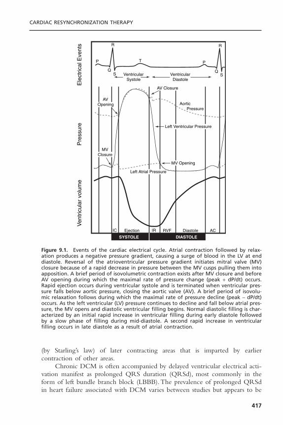
(by Starling’s law) of later contracting areas that is imparted by earlier contraction of other areas.
Chronic DCM is often accompanied by delayed ventricular electrical acti-vation manifest as prolonged QRS duration (QRSd), most commonly in theform of left bundle branch block (LBBB). The prevalence of prolonged QRSdin heart failure associated with DCM varies between studies but appears to be
CARDIAC RESYNCHRONIZATION THERAPY
417
Ven
tric
ular
vol
ume
Pre
ssur
eE
lect
rical
Eve
nts R
P
QVentricular
Systole
AVOpening
MV Opening
AV Closure
MVClosure
Left Ventricular Pressure
Left Atrial Pressure
IC IREjection
SYSTOLE DIASTOLE
RVF ACDiastole
Aortic Pressure
VentricularDiastole
S
T P
R
QS
Figure 9.1. Events of the cardiac electrical cycle. Atrial contraction followed by relax-ation produces a negative pressure gradient, causing a surge of blood in the LV at enddiastole. Reversal of the atrioventricular pressure gradient initiates mitral valve (MV)closure because of a rapid decrease in pressure between the MV cusps pulling them intoapposition. A brief period of isovolumetric contraction exists after MV closure and beforeAV opening during which the maximal rate of pressure change (peak + dP/dt) occurs.Rapid ejection occurs during ventricular systole and is terminated when ventricular pres-sure falls below aortic pressure, closing the aortic valve (AV). A brief period of isovolu-mic relaxation follows during which the maximal rate of pressure decline (peak - dP/dt)occurs. As the left ventricular (LV) pressure continues to decline and fall below atrial pres-sure, the MV opens and diastolic ventricular filling begins. Normal diastolic filling is char-acterized by an initial rapid increase in ventricular filling during early diastole followedby a slow phase of filling during mid-diastole. A second rapid increase in ventricularfilling occurs in late diastole as a result of atrial contraction.

in the range of 25% to 50%. Prolonged QRSd is a potent predictor of mortal-ity in heart failure associated with DCM. In the VEST study, which assessed theefficacy of vesnarinone in patients with DCM and class II-IV heart failure, age,creatinine, ejection fraction, heart rate, and QRSd were found to be indepen-dent predictors of mortality. Cumulative survival from all-cause mortalitydecreased proportionally with QRSd. The relative risk of the widest QRSdgroup was five times greater than the narrowest.9 The association between LBBBin DCM and increased risk of sudden death and total mortality in DCM hassubsequently been demonstrated in large population studies.10
Interventricular coupling refers to coordinated contraction of the rightventricle (RV) and LV. Interventricular delay refers to a relative delay in mechan-ical activation of each ventricle, most commonly LBBB where the RV beginsits contraction before the LV. The delay in onset of left ventricular activationresults in reversal of the normal sequence between right and left ventricular
CARDIAC PACING AND ICDS
418
Figure 9.2. Doppler mitral inflow patterns. This figure shows left ventricular (LV) fillingvelocities from a normal subject, recorded at the level of the mitral leaflet tips (apicalwindow) with pulsed-wave Doppler. The mitral flow velocity curve is composed of thepeak initial velocity (E wave) and the velocity at atrial contraction (A wave). This com-prises the diastolic filling period, which is the interval from the onset of the E velocityto the cessation of the A velocity. In the first diastolic complex, the periods of rapid filling(RF), diastasis (D), and atrial systole (AS) are labeled. In the second complex, early dias-tolic (E) and atrial systolic (A) maximum velocities are indicated. The dashed line denotesthe slope of decay of the peak early diastolic velocity and the arrowheads mark the decel-eration time. The third complex shows how planimetry of the diastolic velocity curve asa function of time yields the velocity-time integral (VTI), which indicates diastolic “strokedistance.”
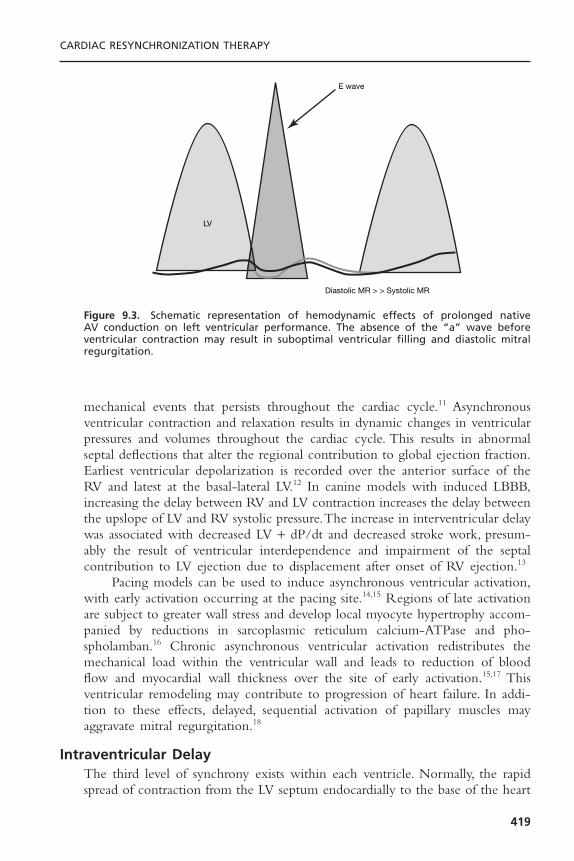
mechanical events that persists throughout the cardiac cycle.11 Asynchronousventricular contraction and relaxation results in dynamic changes in ventricularpressures and volumes throughout the cardiac cycle. This results in abnormalseptal deflections that alter the regional contribution to global ejection fraction.Earliest ventricular depolarization is recorded over the anterior surface of theRV and latest at the basal-lateral LV.12 In canine models with induced LBBB,increasing the delay between RV and LV contraction increases the delay betweenthe upslope of LV and RV systolic pressure.The increase in interventricular delaywas associated with decreased LV + dP/dt and decreased stroke work, presum-ably the result of ventricular interdependence and impairment of the septal contribution to LV ejection due to displacement after onset of RV ejection.13
Pacing models can be used to induce asynchronous ventricular activation,with early activation occurring at the pacing site.14,15 Regions of late activationare subject to greater wall stress and develop local myocyte hypertrophy accom-panied by reductions in sarcoplasmic reticulum calcium-ATPase and pho-spholamban.16 Chronic asynchronous ventricular activation redistributes themechanical load within the ventricular wall and leads to reduction of bloodflow and myocardial wall thickness over the site of early activation.15,17 This ventricular remodeling may contribute to progression of heart failure. In addi-tion to these effects, delayed, sequential activation of papillary muscles mayaggravate mitral regurgitation.18
Intraventricular DelayThe third level of synchrony exists within each ventricle. Normally, the rapidspread of contraction from the LV septum endocardially to the base of the heart
CARDIAC RESYNCHRONIZATION THERAPY
419
E wave
Diastolic MR > > Systolic MR
LV
Figure 9.3. Schematic representation of hemodynamic effects of prolonged native AV conduction on left ventricular performance. The absence of the “a” wave before ventricular contraction may result in suboptimal ventricular filling and diastolic mitralregurgitation.

creates coordinated, efficient contraction. With LBBB, and delayed propagationof the electrical impulse across the LV, the septum begins contraction sub-stantially earlier than the lateral wall. When one segment of the ventricle, suchas the septum, contracts earlier than another segment, such as the lateral wall,the lateral wall stretches, absorbing some of the initial force, then begins its latecontraction, stretching the septum. Shortening of earlier activated regions iswasted work because pressure is low and no ejection is occurring. Delayed short-ening of late activated regions occurs at higher wall stress because the earlyregions have already developed tension, yet it is also characterized by wastedwork because the early regions may now undergo paradoxical stretch.The result-ing contraction is mechanically inefficient, with diminished ejection at anincreased metabolic cost. This is accompanied by increased end systolic volumeand wall stress and reduced LV + dP/dt and diastolic filling time.The net resultis an acute decline in systolic function of approximately 20%.
Intramural DelayStudies of activation maps have shown different activation timing and sequencebetween endocardial and transmural activation. This suggests the possibility ofintramural activation delay between the endocardial and myocardial layer.19 Thenegative effects, if any, of intramural delay on ventricular pumping function, areuncertain.
CARDIAC RESYNCHRONIZATION THERAPYRecognition of the contribution of disordered electrical timing to reduced ventricular performance suggested the possibility that pacing techniques couldfavorably modulate contractile dyssynchrony and delayed AV timing. The fun-damental premise of this therapeutic strategy is that left ventricular preexcita-tion may correct inter- and intraventricular conduction delays and permitoptimization of left-sided AV delay, thereby improving ventricular pumpingfunction.
The first report of the potential hemodynamic benefit of left univentric-ular pacing used epicardial leads placed on the high right atrium and lateral leftventricular (LV) free wall during surgery for aortic valve replacement in patientswith LBBB.20 de Teresa and colleagues20 noted that left ventricular ejection fraction was maximal when septal motion was simultaneous with free wall con-traction and diminished when septal and free wall motion were dyssynchronous,such as during spontaneous activation with LBBB or during right ventricular(RV) apical pacing.The term “cardiac resynchronization” was first used 10 yearslater when Cazeau and colleagues21 used epicardial leads on all four cardiacchambers to modify the ventricular activation sequence and improve hemody-namic performance in heart failure due to dilated cardiomyopathy accompaniedby LBBB.
CARDIAC PACING AND ICDS
420

Mechanisms of Cardiac Resynchronization TherapyImproved Pumping Function: Atrioventricular Optimization and Ventricular
Resynchronization: Correction of physiologically disadvantageous prolongedAV conduction (AV optimization) can be achieved with left ventricular preexci-tation. Optimization of the AV interval during CRT can be conceptualized byexamining mitral flow velocity curves using two-dimensional echocardiography.
When left ventricular preexcitation is inadequate, the result is similar to aprolonged AV interval as shown in Figure 9.3. Note atrial contraction occurstoo early and does not contribute to increased LVEDP (absence of A wave onmitral inflow velocity). Atrial contraction occurs before venous return is com-pleted causing reduced ventricular volume and contractile force. It may also ini-tiate early mitral valve closure, thereby limiting diastolic filling time. DiastolicMR may also occur because once closed, the mitral valve may drift open againbefore ventricular contraction.
When the programmed AV interval is too short, LV preexcitation occurstoo early relative to atrial systole (Fig. 9.4). Note that diastolic filling occursthroughout all of diastole. Atrial contraction now occurs simultaneously withLV contraction resulting in increased left atrial pressure and loss of atrial con-tribution to ventricular systole, reducing cardiac output. A shorter AV intervallengthens the diastolic filling period by abolishing premature mitral valve closuredue to the LV-left atrial pressure gradient seen with long AV delays. This alsoeliminates diastolic MR. However, the diastolic filling period should not be usedas the only guideline to optimize the AV interval. Despite optimization of thediastolic filling period, hemodynamic deterioration will occur at too short anAV interval if atrial contraction occurs against a closed mitral valve. This could
CARDIAC RESYNCHRONIZATION THERAPY
421
E wave
A wave
LV
Systolic MR
Figure 9.4. Schematic representation of hemodynamic effects of too short an AV inter-val on left ventricular performance. The atrial contraction is incomplete at the time ofventricular systole. This leads to ventricular under-filling, systolic mitral regurgitation, andatrial contraction against closed AV valves.

result in a decrease in cardiac output and increase in mean left atrial pressuredespite optimization of the diastolic filling period.
LV preexcitation at the optimal AV interval is shown in Figure 9.5. Therelation of atrial contraction to the onset of ventricular contraction is nowoptimal, resulting in diastolic filling throughout the entire diastolic filling period.An appropriate relation now exists between mechanical left atrial and left ven-tricular contraction so that mean left atrial pressure is maintained at a low levelwith left atrial contraction occurring just before left ventricular contraction.Thiscauses an increase in LVEDP (preload) and cardiac output. Note diastolic MRis eliminated and systolic MR is reduced.
Acute hemodynamic studies have shown that AV delay is a significantdeterminant of changes in all LV systolic parameters (+ dP/dt, aortic systolicpressure, aortic pulse pressure).22 For CRT “responders” (see below). LV + dP/dtand aortic pulse pressure AV delay functions are positive and unimodal, with apeak effect at approximately 50% of the native PR interval. The optimal AVdelays for the same pacing chamber and parameter varied widely among patientsand often differed for pulse pressure and LV + dP/dt within an individual.22 Theacute increase in LV + dP/dt with optimal AV delay may be in the range of15% to 45%.22,23
The hemodynamic benefit of LV preexcitation is primarily due to ventric-ular resynchronization rather than AV optimization, however.The decreased LV +dP/dt and decreased stroke work associated with interventricular delay can beeliminated by CRT13 and improvements in RV to LV delay correlate withimprovements in EF.24 Furthermore, CRT improves pumping function whiledecreasing myocardial energy consumption.25
CARDIAC PACING AND ICDS
422
E wave
A wave
LV
Systolic MR
Figure 9.5. Schematic representation of hemodynamic effects of optimal AV interval onleft ventricular performance. The optimal AV interval prevents mitral regurgitation, max-imizes ventricular filling and reduces mean atrial pressure.

Reverse Left Ventricular Remodeling: In addition to improvement in acutehemodynamic performance, it has now been clearly demonstrated that CRTimproves chronic left ventricular pumping function.This improvement is accom-panied by Doppler echocardiographic (conventional two-dimensional and tissueimaging) evidence of reverse left ventricular remodeling.26–28 These remodelingeffects include reduction in left ventricular volume, redistribution of cardiacmass, reduced mitral orifice size and reduced mitral regurgitation.
Other Effects of Cardiac Resynchronization Therapy: Reduction in Functional Mitral Regurgitation
Functional MR frequently accompanies DCM and results from an imbalancebetween the closing and tethering forces that act on the mitral leaflets and hasbeen elegantly described by Breithardt and colleagues.18 This is strongly depen-dent on alterations in ventricular shape as the tethering forces that act on themitral leaflets are higher in dilated, more spherical ventricles. These geometricchanges alter the balance between tethering and closing forces and impede effective mitral closure. Ventricular dilatation and increased chamber sphericityincrease the distance between the papillary muscles to the enlarged mitralannulus as well as to each other, restricting leaflet motion and increasing theforce needed for effective mitral valve closure. This mitral valve closing force is determined by the systolic left ventricular pressure-left atrial pressure differ-ence, which is called the transmitral pressure gradient. Under these conditions,the mitral regurgitant orifice area will be largely determined by the phasicchanges in transmitral pressure. Increasing the transmitral pressure can reduce the effective regurgitant orifice area. CRT acutely reduces the severity of functional MR and this reduction is quantitatively related to an increase in LV+ DP/dt max and transmitral pressure.18 This is distinct from the reduction inMR due to reduced LV dimensions from remodeling associated with chronicCRT.
Functional mitral regurgitation may also occur due to delayed sequentialactivation of the papillary muscles due to intraventricular delay.18 This accountsfor the acute hemodynamic deterioration reported in some patients after abla-tion of the AV junction and institution of RV apical pacing, which mimicsLBBB.29,30 This can be ameliorated by CRT.31
Implementation of Cardiac Resynchronization TherapyThere are currently three approaches to achieving left ventricular pacing.The transvenous approach uses specially designed delivery sheaths and tools for cannulating the coronary sinus to permit delivery of pacing leads into theepicardial venous circulation serving the left ventricular free wall. Left ventricular pacing lead placement can also be achieved under direct visualiza-tion using a cardiac surgical approach. Finally, transvenous left ventricular endocardial pacing via transseptal puncture has been described in the rare circumstance where neither the transvenous epicardial nor surgical options areviable.32,33
CARDIAC RESYNCHRONIZATION THERAPY
423

Approach to Transvenous Left Ventricular Lead PlacementEarly attempts at epicardial LV pacing via the coronary veins utilized standardendocardial pacing leads designed for right ventricular pacing or coronary sinusleads designed for left atrial pacing.34 This approach was met with predictabledifficulties, including lead dislodgment, high pacing thresholds and inability toreach the target coronary venous branch. Currently available tools and tech-niques achieve a greater than 90% transvenous LV lead placement success rate.
Typically, the coronary sinus is cannulated with a specially designed sheaththat serves as a workstation for LV lead placement. Such sheaths are available ina variety of diameters and shapes intended to overcome unpredictable anatomicvariation in right heart anatomy. Although directional sheaths permit unassistedcannulation of the coronary sinus ostium in some cases, most implanters can-nulate the coronary sinus with a deflectable electrophysiology catheter or a coronary angiography catheter. The sheath is then advanced into the coronarysinus body using the catheter as a railing system (Fig. 9.6).
Once the coronary sinus is successfully cannulated, retrograde venographyis performed to delineate the coronary venous anatomy (Fig. 9.7). This is donewith a standard balloon occlusion catheter and hand injections of contrast mate-rial. Care must be taken to achieve a good seal within the main body of thecoronary sinus in order to obtain maximal opacification of the distal vascula-ture. Underfilling the coronary venous system is a common mistake that mayresult in failure to identify potentially suitable targets for LV pacing lead place-
CARDIAC PACING AND ICDS
424
Figure 9.6. Cannulation of the coronary sinus using a coronary guide catheter and anover-the-wire technique. A: The guidewire has been directed into the coronary sinus bythe sheath in the right atrium. The sheath is advanced over the wire. Note LV lead deliv-ery sheath within main body of coronary sinus. B: The guidewire is withdrawn into thesheath.

ment. Occasionally the inflated balloon will occlude the ostium of a suitablebranch vessel for LV lead placement, therefore occlusive venography at multi-ple levels within the main CS are advisable (see Fig. 9.7).
Currently available transvenous LV pacing leads may be either stylet drivenor use over-the-wire delivery similar to percutaneous coronary intervention.Fixation relies primarily on “wedging” the lead tip into a distal site within thetarget vein such that the outer diameter of the lead closely approximates theinner luminal diameter of the vein. Some current LV lead designs incorporateone or more tines, which may assist with fixation by catching on a valve orpromoting thrombosis, but are probably otherwise irrelevant. Active fixationtechnologies are in development and will likely incorporate various self-retaining bends or cants that compress the distal segment of the lead against theouter wall of the vein and the epicardial surface of the heart.
CARDIAC RESYNCHRONIZATION THERAPY
425
Figure 9.7. Retrograde coronary venogram. Panel A: With the balloon occlusive catheterin the distal coronary sinus there appear to be no satisfactory lateral veins for leadplacement. Panel B: Repeat venogram with the balloon proximal in the coronary sinuspartially fills a more proximal branch missed on the distal injection. Panel C: Subselec-tion of the proximal branch with the inner sheath of the guide system depicts this branchwell. Panel D: Retrograde coronary sinus venogram by the femoral approach in anotherpatient.

Factors Limiting Successful Transvenous Left Ventricular Lead Placement
Complex and unpredictable anatomic and technical considerations may precludesuccessful delivery of the LV lead to an optimal pacing site.
Inability to Cannulate the Coronary Sinus: It is difficult to estimate the truepercentage of cases in which the coronary sinus cannot be cannulated becausethis is clearly influenced by operator experience. It is probably in the range of1% to 5%.When the coronary sinus cannot be located by the superior approach,an adaptation of the inferior approach described for complex electrophysiologyprocedures is often successful in localizing the CS ostium (see Fig. 9.7).
Coronary Venous Anatomy: Absent or Inaccessible Target Veins: The coro-nary venous circulation demonstrates considerably more variability than the parallel arterial circulation (Fig. 9.8). Careful studies of retrograde coronaryvenography have revealed that the anterior interventricular vein is present in99% of patients and the middle cardiac vein is present in 100%.These veins aregenerally undesirable for LV preexcitation because they do not reach the lateactivated portion of the LV free wall. Unfortunately, approximately 50% patientshave only a single vein serving the LV free wall. Anatomically, this is a lateral
CARDIAC PACING AND ICDS
426
Figure 9.8. Three-dimensional reconstruction of epicardial coronary venous anatomyusing computed tomography. (Reproduced with permission from Tada H, et al. Three-dimensional computed tomography of the coronary venous system. J Cardiovasc Electro-physiol 2003;14:1385.)

marginal vein in slightly more than 75% and a true posterior vein that ascendsthe free wall in approximately 50% of patients.35 Thus, as many as 20% of patientsmay not have a vein that reaches the optimal LV free wall site for delivery ofCRT. In some instances target veins are present but too small for cannulationwith existing lead systems, or paradoxically too large to achieve mechanical fixation (Figs. 9.9 and 9.10).
Coronary Venous Tortuousity: Another commonly encountered difficulty intransvenous LV lead placement is tortuousity of the target vessel take-off or mainsegment. These anatomic constraints can be extremely difficult to overcome and often require the use of multiple LV lead designs and delivery systems (Fig. 9.11).
High Left Ventricular Stimulation Thresholds and Phrenic Nerve Stimula-tion: The principal limitation of the transvenous approach is that the selection
CARDIAC RESYNCHRONIZATION THERAPY
427
Figure 9.9. Absence of lateral marginal or posterior cardiac veins serving the LV freewall revealed by retrograde coronary venography.

of sites for pacing is entirely dictated by navigable coronary venous anatomy. Acommonly encountered problem is that an apparently suitable target vein deliv-ers the lead to a site where ventricular capture can be achieved at only veryhigh output voltages or not at all. This presumably relates to the presence ofscar on the epicardial surface of the heart underlying the target vein and cannotbe anticipated by fluoroscopic examination a priori (Fig. 9.12). If this is not suc-cessful, surgical placement of LV leads permits more detailed mapping of viablesites in the anatomic region of interest (see Fig. 9.12).
A second common problem is that the target vein delivers the lead to asite that results in phrenic nerve stimulation and diaphragmatic pacing.This canbe difficult to demonstrate during implantation when the patient is supine and
CARDIAC PACING AND ICDS
428
Figure 9.10. Panel A: RAO and LAO retrograde coronary venograms demonstrating verylarge lateral marginal vein descending toward the left ventricular apex. This patient hasa unipolar ventricular pacing lead that was abandoned with the new ICD system. PanelB: LV lead descended to terminus of lateral marginal vein.
A
B
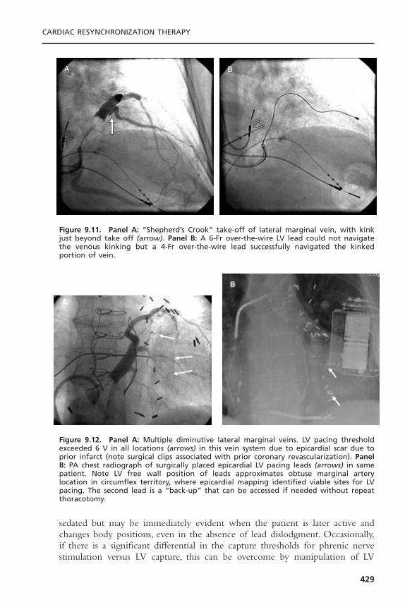
sedated but may be immediately evident when the patient is later active andchanges body positions, even in the absence of lead dislodgment. Occasionally,if there is a significant differential in the capture thresholds for phrenic nervestimulation versus LV capture, this can be overcome by manipulation of LV
CARDIAC RESYNCHRONIZATION THERAPY
429
A B
Figure 9.11. Panel A: “Shepherd’s Crook” take-off of lateral marginal vein, with kinkjust beyond take off (arrow). Panel B: A 6-Fr over-the-wire LV lead could not navigatethe venous kinking but a 4-Fr over-the-wire lead successfully navigated the kinkedportion of vein.
Figure 9.12. Panel A: Multiple diminutive lateral marginal veins. LV pacing thresholdexceeded 6 V in all locations (arrows) in this vein system due to epicardial scar due toprior infarct (note surgical clips associated with prior coronary revascularization). PanelB: PA chest radiograph of surgically placed epicardial LV pacing leads (arrows) in samepatient. Note LV free wall position of leads approximates obtuse marginal artery location in circumflex territory, where epicardial mapping identified viable sites for LVpacing. The second lead is a “back-up” that can be accessed if needed without repeatthoracotomy.
A
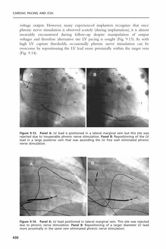
voltage output. However, many experienced implanters recognize that oncephrenic nerve stimulation is observed acutely (during implantation), it is almostinvariably encountered during follow-up despite manipulation of output voltages and therefore alternative site LV pacing is sought (Fig. 9.13). As withhigh LV capture thresholds, occasionally phrenic nerve stimulation can be overcome by repositioning the LV lead more proximally within the target vein(Fig. 9.14).
CARDIAC PACING AND ICDS
430
Figure 9.13. Panel A: LV lead is positioned in a lateral marginal vein but this site wasrejected due to insuperable phrenic nerve stimulation. Panel B: Repositioning of the LVlead in a large posterior vein that was ascending the LV free wall eliminated phrenicnerve stimulation.
Figure 9.14. Panel A: LV lead positioned in lateral marginal vein. This site was rejecteddue to phrenic nerve stimulation. Panel B: Repositioning of a larger diameter LV leadmore proximally in the same vein eliminated phrenic nerve stimulation.

Surgical Approach to Left Ventricular Lead PlacementThe first clinical trial of CRT used a hybrid epicardial LV, endocardial RV pacinglead configuration for multisite ventricular stimulation simply because the tech-nique for transvenous epicardial LV pacing had not been developed.36
There are several current approaches to surgical placement of LV pacingleads. Many surgeons still use a full left lateral thoracotomy, which permits fullvisualization of the LV free wall, but results in significant postoperative pain andan extended recovery period. More recently, a minimally invasive approach hasbeen developed. In this approach, the patient is prepared lying on his or herright side with the left arm suspended overhead. Two or three “porthole” inci-sions are made in the left axillary space for access to the LV free wall (Fig. 9.15).Two epicardial LV leads are placed typically placed using the obtuse marginalbranches of the circumflex coronary artery as regional landmarks, approximately1 cm apical to the mitral annulus. After the leads are placed, the capped termi-nal pins are tunneled to a provisional pocket on the chest wall. The patient isthen re-prepared and draped on his or her back; the provisional pocket is openedand terminal pins are tunneled to the pectoral pocket. One critical differencein patient preparation for surgical versus transvenous LV lead placement is thatit is better to have the patient a little “dry” (well diuresed) in the former anda little “wet” (diuretics withheld) in the latter. In the case of the transvenousapproach, adequate hydration may minimize the risk of contrast-induced renalfailure. In contrast during the surgical approach volume overload may increaselung volume.This increases the hemodynamic consequences of single lung ven-tilation, particularly on right heart function and may limit LV visualization ifcomplete left lung deflation cannot be achieved.
CARDIAC RESYNCHRONIZATION THERAPY
431
Figure 9.15. Surgical approach to minimally invasive placement of epicardial left ven-tricular pacing leads via “port hole” approach (left) or limited left lateral thoracotomy(right). (Courtesy of Medtronic, Inc.)

Optimal Left Ventricular Lead Placement
The optimal site for LV pacing is a complex and unsettled consideration. It isprobably true that the optimal site varies between patients and is likely to bemodified by venous anatomy, regional and global LV mechanical function,myocardial substrate, characterization of electrical delay, and other factors. Thesuccess of resynchronization is dependent on pacing from a site that causes achange in the sequence of ventricular activation that translates to an improve-ment in cardiac performance. Such systolic improvement and mechanical resyn-chronization does not require electrical synchrony12 and explains the lack ofcorrelation between change in QRSd and clinical response to CRT. Ideally thepacing site or sites that produce the greatest hemodynamic effect would beselected.
However, current clinical evidence permits some generalizations LV pacingsite selection for optimal acute hemodynamic response. At least three differentindependent investigations comparing the acute effects of different pacing sitesin similar DCM populations have reported parallel evidence that stimulation siteis a primary determinant of CRT hemodynamic benefit.
Auricchio and colleagues36,37 showed a positive correlation between the magnitude of pulse pressure and LV + dP/dT increases and left ven-tricular pacing site. The percent increases in pulse pressure and LV + dP/dTaveraged over all AV delays were significantly larger at mid-lateral free wall LV epicardial pacing sites compared to any other sample left ventricular region. Furthermore, increases at the mid-anterior sites were smaller than allother sites.
These observations were extended in an analysis of 30 patients enrolled inthe PATCH-CHF II trial (Fig. 9.16).38 Left ventricular stimulation was deliv-ered at the lateral free wall or mid-anterior wall. Free wall sites yielded signi-ficantly larger improvements in LV + dP/dT and pulse pressure than anteriorsites. Furthermore, in one third of patients, stimulation at anterior sites wors-ened acute LV hemodynamic performance, whereas free wall stimulationimproved it, and the opposite pattern was never observed. This difference inacute hemodynamic response correlated with intrinsic conduction delays (Fig. 9.17).This may be interpreted as evidence that stimulating a later activatedLV region produces a larger response because it more effectively restores regional activation synchrony. Thus, the negative effect of anterior wall stimulation at all AV delays in some patients may be due to preexcitation of an already relatively early activated site thereby exaggerating intraventricular dyssynchrony.39
Interestingly, in PATH-CHF a small number of patients with heart failureand LBBB achieved optimal hemodynamic improvement with RV versus LV or biventricular pacing.40 Electroanatomic mapping has demonstrated that the RV apex is frequently delayed in LBBB and in select patients, left ven-tricular preexcitation can be achieved by RV apical pacing due to early
CARDIAC PACING AND ICDS
432
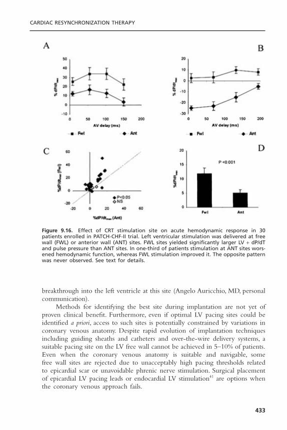
breakthrough into the left ventricle at this site (Angelo Auricchio, MD, personalcommunication).
Methods for identifying the best site during implantation are not yet ofproven clinical benefit. Furthermore, even if optimal LV pacing sites could beidentified a priori, access to such sites is potentially constrained by variations incoronary venous anatomy. Despite rapid evolution of implantation techniquesincluding guiding sheaths and catheters and over-the-wire delivery systems, asuitable pacing site on the LV free wall cannot be achieved in 5–10% of patients.Even when the coronary venous anatomy is suitable and navigable, some free wall sites are rejected due to unacceptably high pacing thresholds relatedto epicardial scar or unavoidable phrenic nerve stimulation. Surgical placementof epicardial LV pacing leads or endocardial LV stimulation41 are options whenthe coronary venous approach fails.
CARDIAC RESYNCHRONIZATION THERAPY
433
Figure 9.16. Effect of CRT stimulation site on acute hemodynamic response in 30patients enrolled in PATCH-CHF-II trial. Left ventricular stimulation was delivered at freewall (FWL) or anterior wall (ANT) sites. FWL sites yielded significantly larger LV + dP/dTand pulse pressure than ANT sites. In one-third of patients stimulation at ANT sites wors-ened hemodynamic function, whereas FWL stimulation improved it. The opposite patternwas never observed. See text for details.
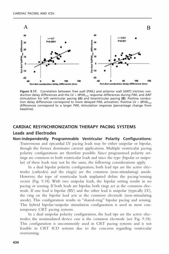
CARDIAC RESYNCHRONIZATION THERAPY PACING SYSTEMSLeads and ElectrodesNon-independently Programmable Ventricular Polarity Configurations:
Transvenous and epicardial LV pacing leads may be either unipolar or bipolar,though the former dominates current applications. Multiple ventricular pacingpolarity configurations are therefore possible. Since programmed polarity set-tings are common to both ventricular leads and since the type (bipolar or unipo-lar) of these leads may not be the same, the following considerations apply.
In a dual bipolar polarity configuration, both lead tips are the active elec-trodes (cathodes) and the ring(s) are the common (non-stimulating) anode.However, the type of ventricular leads implanted define the pacing/sensingvector (Fig. 9.18). With two unipolar leads, the bipolar setting results in nopacing or sensing. If both leads are bipolar, both rings act as the common elec-trode. If one lead is bipolar (RV) and the other lead is unipolar (typically LV),the ring on the bipolar lead acts as the common electrode (non-stimulatinganode). This configuration results in “shared-ring” bipolar pacing and sensing.This hybrid bipolar/unipolar stimulation configuration is used in most con-temporary CRT pacing systems.
In a dual unipolar polarity configuration, the lead tips are the active elec-trodes; the noninsulated device case is the common electrode (see Fig. 9.18).This configuration is uncommonly used in CRT pacing systems and is not feasible in CRT ICD systems due to the concerns regarding ventricular oversensing.
CARDIAC PACING AND ICDS
434
Figure 9.17. Correlation between free wall (FWL) and anterior wall (ANT) intrinsic con-duction delay differences and the LV + dP/dtmax response differences during FWL and ANTstimulation for left ventricular pacing (A) and biventricular pacing (B). Positive conduc-tion delay differences correspond to more delayed FWL activation. Positive LV + dP/dtmax
differences correspond to a larger FWL stimulation response (percentage change frombaseline).
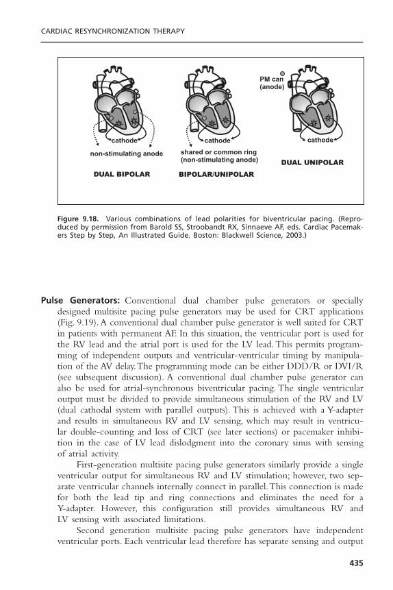
Pulse Generators: Conventional dual chamber pulse generators or speciallydesigned multisite pacing pulse generators may be used for CRT applications(Fig. 9.19). A conventional dual chamber pulse generator is well suited for CRTin patients with permanent AF. In this situation, the ventricular port is used forthe RV lead and the atrial port is used for the LV lead. This permits program-ming of independent outputs and ventricular-ventricular timing by manipula-tion of the AV delay.The programming mode can be either DDD/R or DVI/R(see subsequent discussion). A conventional dual chamber pulse generator canalso be used for atrial-synchronous biventricular pacing. The single ventricularoutput must be divided to provide simultaneous stimulation of the RV and LV(dual cathodal system with parallel outputs). This is achieved with a Y-adapterand results in simultaneous RV and LV sensing, which may result in ventricu-lar double-counting and loss of CRT (see later sections) or pacemaker inhibi-tion in the case of LV lead dislodgment into the coronary sinus with sensingof atrial activity.
First-generation multisite pacing pulse generators similarly provide a singleventricular output for simultaneous RV and LV stimulation; however, two sep-arate ventricular channels internally connect in parallel.This connection is madefor both the lead tip and ring connections and eliminates the need for a Y-adapter. However, this configuration still provides simultaneous RV and LV sensing with associated limitations.
Second generation multisite pacing pulse generators have independent ventricular ports. Each ventricular lead therefore has separate sensing and output
CARDIAC RESYNCHRONIZATION THERAPY
435
Figure 9.18. Various combinations of lead polarities for biventricular pacing. (Repro-duced by permission from Barold SS, Stroobandt RX, Sinnaeve AF, eds. Cardiac Pacemak-ers Step by Step, An Illustrated Guide. Boston: Blackwell Science, 2003.)

CARDIAC PACING AND ICDS
436
Figure 9.19. Various pulse generator configurations for biventricular pacing. (Repro-duced by permission from Barold SS, Stroobandt RX, Sinnaeve AF, eds. Cardiac Pacemak-ers Step by Step, An Illustrated Guide. Boston: Blackwell Science, 2003.)
circuits. This arrangement permits optimal programming of outputs and timedelay between RV and LV stimulation for each patient. It also eliminates thepotential complications of biventricular sensing.
Biventricular or Univentricular Stimulation for CardiacResynchronization Therapy
It is important to note that uncertainty about the requirement of RV stimula-tion during CRT, uneasiness about long-term LV lead performance, and unavail-ability of pacing systems with separately programmable ventricular outputsinfluenced the use of biventricular pacing, as opposed to left univentricularpacing, in large scale randomized clinical trials. A particular concern is LV leaddislodgment which risks for potentially lethal bradycardia and has a reportedincidence of 5% to 10% in larger studies.42–44 However, there is some scientificevidence that right ventricular stimulation might not be necessary for optimalCRT response. Left univentricular pacing alone has acute hemodynamic effectsthat are similar or superior to those achieved with biventricular pacing in some patients.27,45–47 Blanc and co-workers recently extended these observations.48
Functional capacity (6 minute walk and maximal O2 uptake), ventricular sizeand function, and blood norepinephrine levels before and after 12 months ofleft univentricular pacing were evaluated in 22 patients with dilated cardiomy-opathy, LBBB NYHA class III or IV heart failure. The LV lead was placed ina lateral coronary vein when possible and all patients had sinus rhythm to allow atrial synchronous left univentricular pacing with an AV delay initiallyprogrammed to 100 milliseconds. Significant improvements in functional capac-ity, echocardiographic mitral regurgitation, and LV end-diastolic diameter wereobserved with favorable trend toward improvement in LVEF. Thus these resultsare encouraging and support persistent benefit (at least to 1 year) of left uni-ventricular pacing in some patients.
At present, it is not possible to identify patients who will respond betterto LV alone compared to biventricular pacing, or neither; and it is not clearhow to identify the optimal pacing site. Other factors will warrant RV leadplacement in many patients. Patients with reduced LV ejection fraction and atleast moderately symptomatic heart failure are at risk for sudden cardiac deathdue to ventricular arrhythmias and this risk can be reduced by ICD therapy.49–52
Current ICD systems require RV lead for tachyarrhythmia sensing and highvoltage therapies and have a long record of safety and reliability in this regard.Further data on the safety and reliability of LV leads for tachyarrhythmia sensingand possibly defibrillation53 are essential before RV leads are abandoned in CRTpacing and CRT defibrillation systems. It is likely that systems incorporating an RV lead will continue to predominate. If LV pacing systems can become asreliable as RV pacing systems, the paradigm could shift.
CARDIAC RESYNCHRONIZATION THERAPY
437

PROGRAMMING CONSIDERATIONS IN CARDIACRESYNCHRONIZATION THERAPYPacing Modes
It is axiomatic that for maximal delivery of CRT, ventricular pacing must becontinuous.
DDD mode guarantees AV synchrony and ventricular pacing with all atrialevents in the physiologic heart rate range. However, DDD mode increases theprobability of atrial pacing (depending upon programmed lower rate limit) thatmay alter the left sided AV timing relationship due to interatrial conductiontime and atrial pacing latency.
VDD mode guarantees the absence of atrial pacing and synchronizes allatrial events to ventricular pacing at the programmed AV delay. However, if thesinus rate is below the lower programmed rate limit, AV synchrony is lostbecause the VDD mode is operationally VVI.
Although conventional dual-chamber pacemakers are not designed forbiventricular pacing and generally do not allow programming of an AV delayof zero, or near zero, they are being increasingly used with their shortest AVdelay (0 to 30 milliseconds) for CRT in patients with permanent AF. The ad-vantages include programming flexibility, elimination of the Y-adapter (requiredfor conventional VVIR devices), protection against far-field sensing of atrialactivity (an inherent risk of dual cathodal devices with simultaneous sensingfrom both ventricles), and cost.When a conventional dual-chamber PM is usedfor CRT, the LV lead is usually connected to the atrial port and the RV leadto the ventricular port. This provides for (1) LV stimulation before RV activa-tion (LV preexcitation), and (2) protection against ventricular asystole related tooversensing of far-field atrial activity when the LV lead is dislodged toward theAV groove. The DVIR mode is ideally suited for this application. The DVIRmode behaves like the VVIR mode except that there are always two closelycoupled independent ventricular stimuli thereby facilitating comprehensive eval-uation of RV and LV pacing and sensing performance. The DVIR mode alsoprovides absolute protection against far-field sensing of atrial activity in case ofLV lead dislodgment because no sensing occurs on the “atrial” (LV) lead in theDVIR mode.
Ventricular Double-Counting Causing Loss of CardiacResynchronization Therapy and Spurious Ventricular Therapies
In first generation CRT and CRTD systems, pacing and sensing occurs fromRV and LV simultaneously. Double counting involves the spontaneous wideQRS complex of LBBB (Fig. 9.20). This produces temporal separation of RVand LV electrograms (EGM). The degree of separation depends on the severityof the interventricular conduction delay and the location of the electrodes.TheLV EGM may be sensed sometime after detection of the RV EGM if the LVsignal extends beyond the relatively short ventricular blanking period initiatedby RV sensing. This is more likely to occur when a long post-ventricular atrial
CARDIAC PACING AND ICDS
438

refractory period (PVARP) is programmed. In this circumstance, sinus P waves,particularly during sinus tachycardia and first-degree AV block (which arecommon in heart failure patients) that displace the P wave into the PVARPwhere it cannot be tracked. This results in loss of ventricular pacing and CRT.This situation is commonly triggered by PVARP extensions after a prematureventricular contraction (PVC). Spontaneous AV conduction occurs in the formof a preempted upper rate Wenckebach response with loss of ventricular pacingand CRT (Fig. 9.21). In CRTD systems, this may result in ventricular doublecounting and misclassification of sinus tachycardia or rapidly conducted AF asventricular tachycardia resulting in spurious therapies. During true ventricularepisodes, such as ventricular tachycardia, the LV EGM may precede the RVEGM and may result in spurious shocks because the rate is misclassified as VF.
Failure to deliver CRT at high sinus rates can be minimized by shorten-ing the PVARP, increasing the upper tracking limit and deactivating the PVCresponse in the DDD/R mode. Additionally, atrial fibrillation should be aggres-sively treated to prevent rapid ventricular response and emergence of sponta-neous QRS complexes. New CRT systems prevent ventricular double-countingby using an IVRP (interventricular ventricular refractory period). Ventricularsensed events (i.e., LV sensing) during the IVRP do not restart PVARP (Fig. 9.22).
Atrioventricular OptimizationAV optimization is important for maximal hemodynamic response to CRT butnot essential, because ventricular pumping function can be improved by CRTeven in the presence of permanent AF. Nonetheless, acute hemodynamic studieshave consistently demonstrated that AV optimization “re-times” the left atrial-left ventricular relationship and can result in 15% to 40% improvement in indices
CARDIAC RESYNCHRONIZATION THERAPY
439
Figure 9.20. Origin of temporally dispersed RV and LV electrograms during biventricu-lar sensing in left bundle branch block.
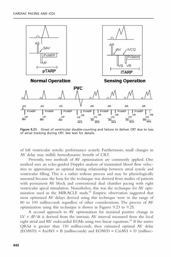
of left ventricular systolic performance acutely. Furthermore, small changes inAV delay may nullify hemodynamic benefit of CRT.
Presently, two methods of AV optimization are commonly applied. Onemethod uses an echo-guided Doppler analysis of transmitral blood flow veloc-ities to approximate an optimal timing relationship between atrial systole andventricular filling. This is a rather tedious process and may be physiologicallyunsound because the basis for the technique was derived from studies of patientswith permanent AV block and conventional dual chamber pacing with rightventricular apical stimulation. Nonetheless, this was the technique for AV opti-mization used in the MIRACLE study.42 Empiric observation suggested thatmost optimized AV delays derived using this technique were in the range of 80 to 100 milliseconds regardless of other considerations. The process of AVoptimization using this technique is shown in Figures 9.23 to 9.25.
A second approach to AV optimization for maximal positive change in LV + dP/dt is derived from the intrinsic AV interval measured from the localright atrial and RV endocardial EGMs using two linear equations.54 If the nativeQRSd is greater than 150 milliseconds, then estimated optimal AV delay(EOAVD) = AxiAVI + B (milliseconds) and EOAVD = CxiAVI + D (millisec-
CARDIAC PACING AND ICDS
440
Figure 9.21. Onset of ventricular double-counting and failure to deliver CRT due to lossof atrial tracking during CRT. See text for details.

onds), where iAVI = intrinsic AV interval, A = 0.7, B = -55 milliseconds, andD = 0 milliseconds. These regression formulas can be very closely approximateby the following simple rules: the estimated optimal programmed AV delay forpatients with QRSd greater than 150 milliseconds is 50% of the intrinsic AV interval and 75% for QRSd of 120 to 150 milliseconds. This strategy was used in the study design of the Comparison of Medical Therapy, Pacing, andDefibrillation in Heart Failure (COMPANION) trial44 that showed signifi-cant reductions in mortality and heart failure hospitalizations with CRT at 1year.
It is almost certainly true that the optimal AV delay will likely differ as heart rate and cardiac loading conditions change, such that the optimal AVdelay at one point in time may not predict optimal AV timing under other conditions. Furthermore, the importance of AV delay optimization at rest forchronic clinical and hemodynamic effect remains to be shown.
Pacing OutputsIt is critically important that voltage output be adjusted to exceed ventricularcapture threshold for LV and RV in common cathodal devices. Since there are
CARDIAC RESYNCHRONIZATION THERAPY
441
Figure 9.22. Prevention of ventricular double-counting with an interventricular refrac-tory period. A = atrium; RV = right ventricle; LV = left ventricle; R = refractory event; S = sensed event; P = paced event. See text for details.
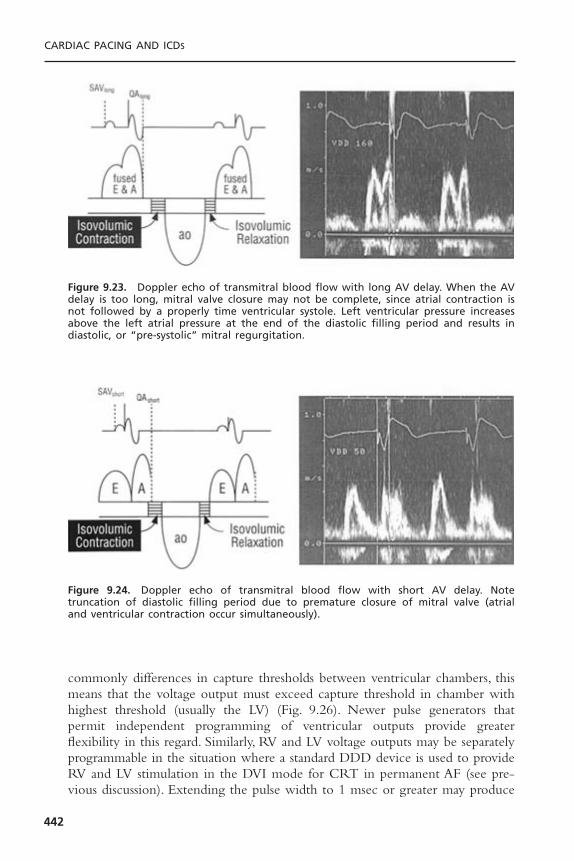
commonly differences in capture thresholds between ventricular chambers, thismeans that the voltage output must exceed capture threshold in chamber withhighest threshold (usually the LV) (Fig. 9.26). Newer pulse generators thatpermit independent programming of ventricular outputs provide greater flexibility in this regard. Similarly, RV and LV voltage outputs may be separatelyprogrammable in the situation where a standard DDD device is used to provideRV and LV stimulation in the DVI mode for CRT in permanent AF (see pre-vious discussion). Extending the pulse width to 1 msec or greater may produce
CARDIAC PACING AND ICDS
442
Figure 9.23. Doppler echo of transmitral blood flow with long AV delay. When the AVdelay is too long, mitral valve closure may not be complete, since atrial contraction isnot followed by a properly time ventricular systole. Left ventricular pressure increasesabove the left atrial pressure at the end of the diastolic filling period and results in diastolic, or “pre-systolic” mitral regurgitation.
Figure 9.24. Doppler echo of transmitral blood flow with short AV delay. Note truncation of diastolic filling period due to premature closure of mitral valve (atrial and ventricular contraction occur simultaneously).

CARDIAC RESYNCHRONIZATION THERAPY
443
Figure 9.25. Doppler echo transmitral blood flow at optimal AV delay. The relation ofatrial contraction to the onset of ventricular contraction is now optimal, resulting in dias-tolic filling throughout the entire diastolic filling period. An appropriate relation nowexists between mechanical left atrial and left ventricular contraction so that mean leftatrial pressure is maintained at a low level with left atrial contraction occurring justbefore left ventricular contraction. AV optimization is noted by return of the normal E-A separation. Transmitral flood and LV diastolic filling time are increased, which improvesto increased cardiac output. If a large amount of diastolic MR can be abolished, a ben-eficial effect is obtained because of lower left atrial and higher left ventricular preloadat the onset of ventricular contraction.
0 0.5 ms 1 ms 1.5 mspulse duration (in ms)
2 ms 2.5 ms
2V
3V
4V
5V
(0.3 ms & 2.5V)
forbidden zoneno capturepossible
region wherecapture isassured
amplitude (in volts)
RV < 0.5V @ 0.5 msLV 2V @ 0.5 ms
1V
Figure 9.26. Strength-duration curve considerations for biventricular pacing. In commoncathodal systems, the ventricular output must exceed the capture threshold for thechamber with the highest threshold, typically the LV.

consistent capture at sites that have unacceptable thresholds at standard pulsewidths.
Interventricular TimingImplantation of a biventricular pacing system with separately programmable LVand RV stimulation outputs and timing delay would allow adjustments to bemade during follow-up. It is presently unclear what benefit, if any, manipula-tion of interventricular timing would provide during biventricular pacing.27 Thisis highlighted by the emerging evidence (see earlier) that univentricular left ven-tricular pacing is probably either equivalent or superior to biventricular pacingacutely and chronically.
CARDIAC RESYNCHRONIZATION THERAPY PACEMAKERELECTROCARDIOGRAPHY/DETERMINING LEFT VENTRICULAR AND RIGHT VENTRICULAR CAPTURE
The 12-lead ECG is essential to ascertain RV and LV capture during follow-up of CRT systems without separately programmable ventricularoutputs. It is recognized that five distinct 12-lead ventricular activation patterns may be seen during threshold determination. These are (1) intrinsicrhythm during loss of RV and LV capture or pacing inhibition (native QRS),(2) isolated RV stimulation, (3) isolated LV stimulation, (4) biventricular stimulation, and (5) biventricular stimulation with anodal capture (Figs. 9.27 to9.32).
Ventricular pacing thresholds should ideally be performed independentlyand in the VVI mode at a rate superseding the prevailing ventricular rate toobtain continuous ventricular capture without fusion. Alternately, thresholds canbe performed in the VDD or DDD mode at very short AV delays to ensurefull ventricular capture without fusion. In general, it is advisable to initiatethreshold determinations at maximum output (voltage and pulse duration)because there is often a significant differential in capture thresholds between RVand LV.
In devices without separately programmable ventricular outputs RV andLV capture can only be determined by ECG analysis during common ventric-ular voltage decrement. This requires inspection of a 12-lead ECG to demon-strate a change in electrical axis that confirms independent LV and RV capture.
Pacing from the RV apex produces a negative paced QRS complex in theinferior leads simply because the activation starts in the inferior part of the heartand travels superiorly away from the inferior leads.The mean QRS frontal planaxis is superior either in the left or right superior quadrant. Pacing from theRVOT produces a frontal plane axis that is “normal,” meaning, inferiorly directed(positive QRS in inferior leads). Isolated LV pacing produces a rightward axis,similar to maximal ventricular preexcitation over a left-sided accessory pathway.Biventricular pacing (RV + LV) produces a right superior axis as a result of
CARDIAC PACING AND ICDS
444

fusion of RV and LV electrical axes. A qR or Qr complex in lead I is rare inuncomplicated RV apical pacing. It is present in 90% of cases of biventricularpacing. In biventricular pacing, loss of the q or Q wave in lead I is 100% pre-dictive of loss of LV capture.
CARDIAC RESYNCHRONIZATION THERAPY
445
Figure 9.27. Mean QRS axis in the frontal plane during ventricular pacing at differentsites and configurations. (Reproduced by permission from Barold SS, Stroobandt RX, Sinnaeve AF, eds. Cardiac Pacemakers Step by Step, An Illustrated Guide. Boston: Blackwell Science, 2003.)

CARDIAC PACING AND ICDS
446
Figure 9.28. EKG QRS patterns during RV pacing from different sites. (Reproduced bypermission from Barold SS, Stroobandt RX, Sinnaeve AF, eds. Cardiac Pacemakers Step byStep, An Illustrated Guide. Boston: Blackwell Science, 2003.)

CARDIAC RESYNCHRONIZATION THERAPY RESPONDERS AND NONRESPONDERS
Despite the technical limitations for achieving reliable, long-term transvenousLV stimulation, the majority of appropriately selected patients respond to CRT.Nonetheless, approximately 18% to 30% of patients fail to respond clinically toCRT.42,55,56 In some cases, failure to respond may simply indicate that despite
CARDIAC RESYNCHRONIZATION THERAPY
447
Figure 9.29. EKG QRS patterns during LV free wall pacing. (Reproduced by permissionfrom Barold SS, Stroobandt RX, Sinnaeve AF, eds. Cardiac Pacemakers Step by Step, AnIllustrated Guide. Boston: Blackwell Science, 2003.)

delayed ventricular activation, mechanical activation is not dyssynchronous.57,58
It is likely, however, that technical limitations are a major factor. In theMIRACLE study a lateral marginal vein site serving the LV free wall wasobtained in only 43% of patients. This number is probably an overestimatebecause the larger diameter stylet driven leads used during MIRACLE typicallytraverse the “Shepherd’s Crook” curve of the anterior interventricular veinbefore they descend the LV. Many of the “lateral” sites were probably reallyanterolateral rather than true lateral marginal vein sites. Thus, at least 57% ofpatients in MIRACLE may have had suboptimal LV lead positions. It is con-ceivable that some of these patients were actually made worse by CRT due toLV pacing at suboptimal sites, particularly among the patients with relativelynarrow QRSd (less than 150 milliseconds).38 As reviewed previously, CRT withstimulation at a LV free wall site consistently improves short-term systolic func-tion more than stimulation at an anterior site does (Figs. 9.33 and 9.34). Thesedifferences may account for the varied results and large individual differenceobserved among clinical studies.
CARDIAC PACING AND ICDS
448
Figure 9.30. Analysis of EKG QRS patterns to ascertain RV and LV capture in CRT systemswithout separately programmable ventricular outputs. (Reproduced by permission fromBarold SS, Stroobandt RX, Sinnaeve AF, eds. Cardiac Pacemakers Step by Step, An Illus-trated Guide. Boston: Blackwell Science, 2003.)

CARDIAC RESYNCHRONIZATION THERAPY
449
Figure 9.31. Twelve lead ECGs of uni- and biventricular pacing. Panel A: Non-pacedintrinsic ventricular activation with LBBB. Panel B: RV only pacing. Panel C: LV only pacing.Panel D: Biventricular pacing. Note the markedly shortened QRS duration.
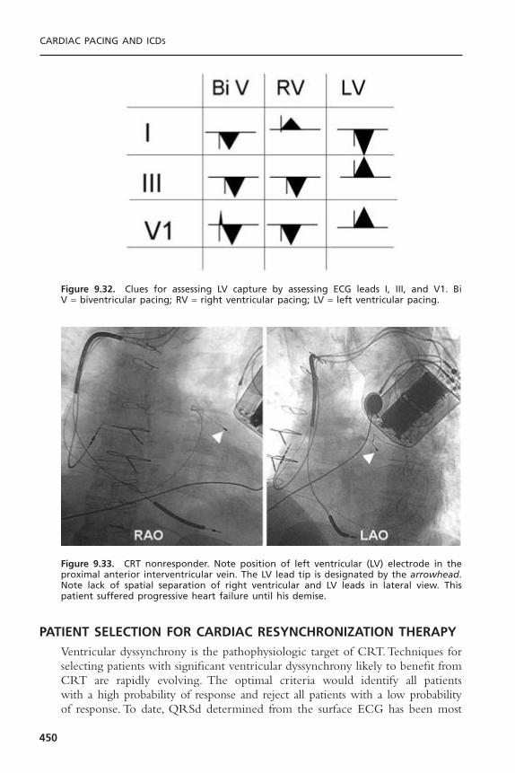
PATIENT SELECTION FOR CARDIAC RESYNCHRONIZATION THERAPYVentricular dyssynchrony is the pathophysiologic target of CRT.Techniques forselecting patients with significant ventricular dyssynchrony likely to benefit fromCRT are rapidly evolving. The optimal criteria would identify all patients with a high probability of response and reject all patients with a low probabilityof response. To date, QRSd determined from the surface ECG has been most
CARDIAC PACING AND ICDS
450
Figure 9.32. Clues for assessing LV capture by assessing ECG leads I, III, and V1. Bi V = biventricular pacing; RV = right ventricular pacing; LV = left ventricular pacing.
Figure 9.33. CRT nonresponder. Note position of left ventricular (LV) electrode in theproximal anterior interventricular vein. The LV lead tip is designated by the arrowhead.Note lack of spatial separation of right ventricular and LV leads in lateral view. Thispatient suffered progressive heart failure until his demise.
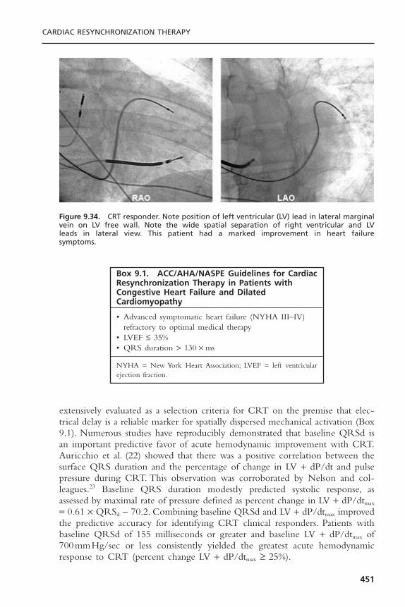
extensively evaluated as a selection criteria for CRT on the premise that elec-trical delay is a reliable marker for spatially dispersed mechanical activation (Box9.1). Numerous studies have reproducibly demonstrated that baseline QRSd isan important predictive favor of acute hemodynamic improvement with CRT.Auricchio et al. (22) showed that there was a positive correlation between thesurface QRS duration and the percentage of change in LV + dP/dt and pulsepressure during CRT. This observation was corroborated by Nelson and col-leagues.23 Baseline QRS duration modestly predicted systolic response, asassessed by maximal rate of pressure defined as percent change in LV + dP/dtmax
= 0.61 ¥ QRSd - 70.2. Combining baseline QRSd and LV + dP/dtmax improvedthe predictive accuracy for identifying CRT clinical responders. Patients withbaseline QRSd of 155 milliseconds or greater and baseline LV + dP/dtmax of700mmHg/sec or less consistently yielded the greatest acute hemodynamicresponse to CRT (percent change LV + dP/dtmax ≥ 25%).
CARDIAC RESYNCHRONIZATION THERAPY
451
Figure 9.34. CRT responder. Note position of left ventricular (LV) lead in lateral marginalvein on LV free wall. Note the wide spatial separation of right ventricular and LV leads in lateral view. This patient had a marked improvement in heart failure symptoms.
Box 9.1. ACC/AHA/NASPE Guidelines for CardiacResynchronization Therapy in Patients withCongestive Heart Failure and DilatedCardiomyopathy
• Advanced symptomatic heart failure (NYHA III–IV)refractory to optimal medical therapy
• LVEF £ 35%• QRS duration > 130 ¥ ms
NYHA = New York Heart Association; LVEF = left ventricularejection fraction.
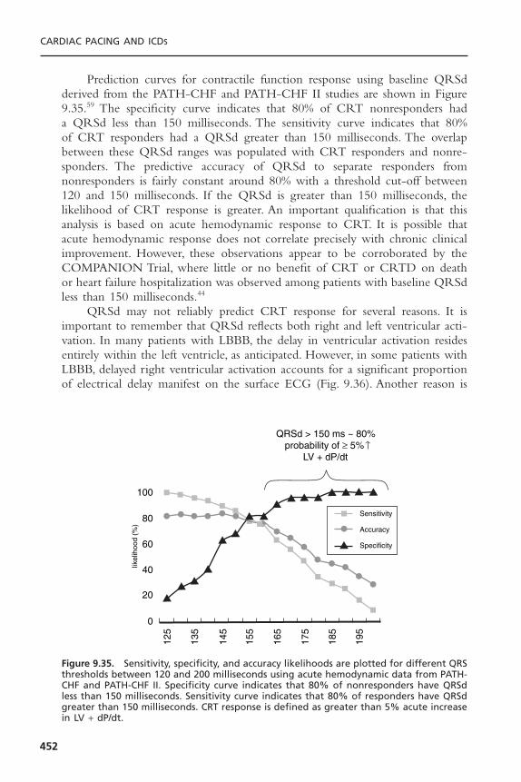
Prediction curves for contractile function response using baseline QRSdderived from the PATH-CHF and PATH-CHF II studies are shown in Figure9.35.59 The specificity curve indicates that 80% of CRT nonresponders had a QRSd less than 150 milliseconds. The sensitivity curve indicates that 80% of CRT responders had a QRSd greater than 150 milliseconds. The overlapbetween these QRSd ranges was populated with CRT responders and nonre-sponders. The predictive accuracy of QRSd to separate responders from nonresponders is fairly constant around 80% with a threshold cut-off between120 and 150 milliseconds. If the QRSd is greater than 150 milliseconds, thelikelihood of CRT response is greater. An important qualification is that thisanalysis is based on acute hemodynamic response to CRT. It is possible thatacute hemodynamic response does not correlate precisely with chronic clinicalimprovement. However, these observations appear to be corroborated by theCOMPANION Trial, where little or no benefit of CRT or CRTD on deathor heart failure hospitalization was observed among patients with baseline QRSdless than 150 milliseconds.44
QRSd may not reliably predict CRT response for several reasons. It isimportant to remember that QRSd reflects both right and left ventricular acti-vation. In many patients with LBBB, the delay in ventricular activation residesentirely within the left ventricle, as anticipated. However, in some patients withLBBB, delayed right ventricular activation accounts for a significant proportionof electrical delay manifest on the surface ECG (Fig. 9.36). Another reason is
CARDIAC PACING AND ICDS
452
125
135
145
155
165
175
185
195
20
40
60
80
100
Sensitivity
Accuracy
Specificity
likel
ihoo
d (%
)
0
QRSd > 150 ms ~ 80%probability of ≥ 5%
LV + dP/dt
Figure 9.35. Sensitivity, specificity, and accuracy likelihoods are plotted for different QRSthresholds between 120 and 200 milliseconds using acute hemodynamic data from PATH-CHF and PATH-CHF II. Specificity curve indicates that 80% of nonresponders have QRSdless than 150 milliseconds. Sensitivity curve indicates that 80% of responders have QRSdgreater than 150 milliseconds. CRT response is defined as greater than 5% acute increasein LV + dP/dt.
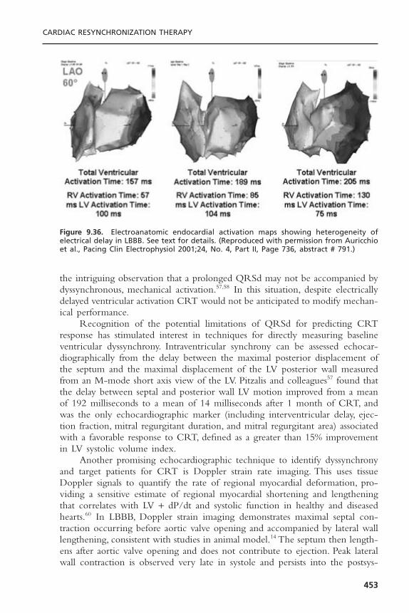
the intriguing observation that a prolonged QRSd may not be accompanied bydyssynchronous, mechanical activation.57,58 In this situation, despite electricallydelayed ventricular activation CRT would not be anticipated to modify mechan-ical performance.
Recognition of the potential limitations of QRSd for predicting CRTresponse has stimulated interest in techniques for directly measuring baselineventricular dyssynchrony. Intraventricular synchrony can be assessed echocar-diographically from the delay between the maximal posterior displacement ofthe septum and the maximal displacement of the LV posterior wall measuredfrom an M-mode short axis view of the LV. Pitzalis and colleagues57 found thatthe delay between septal and posterior wall LV motion improved from a meanof 192 milliseconds to a mean of 14 milliseconds after 1 month of CRT, andwas the only echocardiographic marker (including interventricular delay, ejec-tion fraction, mitral regurgitant duration, and mitral regurgitant area) associatedwith a favorable response to CRT, defined as a greater than 15% improvementin LV systolic volume index.
Another promising echocardiographic technique to identify dyssynchronyand target patients for CRT is Doppler strain rate imaging. This uses tissueDoppler signals to quantify the rate of regional myocardial deformation, pro-viding a sensitive estimate of regional myocardial shortening and lengtheningthat correlates with LV + dP/dt and systolic function in healthy and diseasedhearts.60 In LBBB, Doppler strain imaging demonstrates maximal septal con-traction occurring before aortic valve opening and accompanied by lateral walllengthening, consistent with studies in animal model.14 The septum then length-ens after aortic valve opening and does not contribute to ejection. Peak lateralwall contraction is observed very late in systole and persists into the postsys-
CARDIAC RESYNCHRONIZATION THERAPY
453
Figure 9.36. Electroanatomic endocardial activation maps showing heterogeneity ofelectrical delay in LBBB. See text for details. (Reproduced with permission from Auricchioet al., Pacing Clin Electrophysiol 2001;24, No. 4, Part II, Page 736, abstract # 791.)
tolic period. During CRT, systolic contraction can be demonstrated to occursimultaneously in both septal and lateral walls, contributing equally to ejection.61
The use of this technique in patient selection for CRT remains to be definedin clinical trials but preliminary results appear encouraging.Ventricular dyssyn-chrony detected by tissue Doppler imaging has been shown to predict acuteand chronic response (including remodeling) to CRT in several studies.62–65
Numerous clinical variables have also been evaluated for predicting likeli-hood of CRT responsiveness. Baseline contractile function indexed by LV +dP/dtmax has been shown to inversely correlate with its subsequent changeduring LV pacing. Heart failure functional class is positively correlated withCRT response. In several studies, equivalent benefit was observed with CRT inNYHA class III-IV patients but no significant benefit in class II.42,43 Left ventricular ejection fraction has not been shown to correlate with likelihood ofCRT response in any study. Some studies have suggested that ischemic car-diomyopathy is less likely to respond to CRT than non-ischemic cardiomyopa-thy,55 but not others.42,44 Sinus rhythm does not appear to be necessary for CRTresponse. Patients in permanent AF had a similar acute hemodynamic responseas sinus rhythm in PATH-CHF and similar long-term function improvementsin other trials.42,66–68 There is very limited data on CRT in RBBB that suggeststhe possibility of similar intermediate term response as LBBB in one trial69 butnot another.44
Further complicating the matter of patient selection for CRT is the fasci-nating observation that some patients with DCM and significant mechanicaldyssynchrony have a normal or near-normal QRSd.70–73
In summary, 80% of patients with QRSd greater than 150 milliseconds willhave a hemodynamic improvement with CRT and the probability of responseis positively correlated with QRS duration. Patients with QRSd less than 150milliseconds are less likely to respond to CRT though this is not uniformly true.Improvements in asynchrony seem to be the determinant of the improvementsobtained with CRT, and this may be independent of QRS duration. Patientswith more advanced heart failure symptoms are more likely to respond to CRTthan patients with less severe symptoms. There is limited data suggesting thatpatients with non-ischemic cardiomyopathy respond more consistently thanischemic CMP and LBBB more consistently than RBBB. Permanent atrial fibrillation does not preclude CRT response.
Finally, RV apical pacing alone may cause prolonged QRSd and ventricu-lar desynchronization. Ventricular desynchronization imposed by ventricularpacing even when AV synchrony is preserved causes increased left atrial diam-eters and reduced LV fractional shortening and is associated with increased risksof atrial fibrillation, heart failure and death among patients with normal base-line QRSd.74,75 Therefore, it is logical to speculate that multisite (RV + LV) oralternate single site (LV) pacing may be more physiologic among patients inwhom ventricular dyssynchrony is due to unavoidable ventricular pacing (i.e.,persistent heart block). Intriguing studies suggest that pacing at the LV septumor apex maintains ventricular pumping function at sinus rhythm levels despite
CARDIAC PACING AND ICDS
454
pacing-induced QRSd prolongation, possibly because of early engagement ofthe specialized conduction system resulting in a more physiologic propagationof electrical conduction.76
CLINICAL TRIALS OF CARDIAC RESYNCHRONIZATION THERAPYCRT is an effective adjunctive treatment for moderately-severely symptomaticheart failure associated with depressed left ventricular function and ventriculardyssynchrony.42,66,77 The aggregate experience with CRT among clinical trialsinvolving more than 3500 patients demonstrates a consistent clinical benefit(Table 9.1). The magnitude of the benefits is modest and concordant. Theseinclude about a 1-step improvement in NYHA class, a 10-point improvementin quality of life measures, a 1 to 2mL/kg/min improvement in peak VO2, a 50to 70 meter improvement in 6-minute hall walk, and a trend toward reducedheart failure hospitalizations. A meta-analysis of randomized trials of CRT usingthese first-generation pacing systems in 1634 patients found that heart failuredeaths were reduced by 51% (from 3.5% to 1.7%) and heart failure hospitaliza-tions were reduced by 29%.78
CLINICAL TRIALS OF CARDIAC RESYNCHRONIZATION THERAPYWITH IMPLANTABLE CARDIOVERTER-DEFIBRILLATORS
Sudden cardiac death is the leading cause of mortality in the United States. Itis estimated that 200,000 to 400,000 sudden deaths occur annually.79 The vastmajority of these deaths occur among patients with symptomatic heart failureassociated with reduced left ventricular function.
Survival from out-of-hospital cardiac arrest remains abysmal; it is estimatedthat less than 20% of victims will leave the hospital alive.80 The principal reasonfor this dismal statistic is unavailability, or delayed time to, successful defibrilla-tion. Prevention, or at least effective treatment, of the first episode of cardiacarrest is thus critically important.These realities have focused attention on iden-tification and treatment of patients at risk for sudden death due to ventriculararrhythmias.
The results of large scale randomized treatment trials in patients withreduced left ventricular function and VF or hemodynamically unstable sustaineduniform VT that occurs spontaneously or can be induced consistently demonstrate a survival advantage associated with ICD therapy compared toantiarrhythmic drugs.49,51,81–83 Accordingly, ICD therapy can be recommended asfirst-line treatment for primary and secondary prevention of sudden cardiacdeath in these settings.
A similar mortality benefit for ICD therapy was subsequently demonstratedin MADIT II among patients with ischemic cardiomyopathy and left ventricu-lar ejection fraction less than 30% without prior electrophysiology study.50 Thesefindings were extended in SCD-HeFT, which demonstrated a 23% mortalityreduction among patients with ischemic or non-ischemic cardiomyopathy,
CARDIAC RESYNCHRONIZATION THERAPY
455

CA
RD
IAC
PAC
ING
AN
D IC
DS
456
Table 9.1. Randomized Trials of CRT: Enrollment Criteria
Study Design N NYHA QRSd LVEF LVEDD
PATH-CHF Randomized, single blind, 42 II-IV >120 <35 NAcontrolled
VIGOR-CHF Randomized, controlled 53 II-IV >120 <30 NAPATH-CHF II Acute hemodynamic 43 II-IV >120 <30 NAInSync OUS Uncontrolled 81 III-IV >150 <35 >60MUSTIC Uncontrolled 67 III-IV >150 <35 >60MIRACLE Randomized, double- 266 III-IV >130 <35 >55
blind, controlled
Study Baseline NYHA 3-month NYHA Baseline QRSd 3-month QRSd Baseline LVEF 3-month LVEF
PATH-CHF 3.0 ± 0.3 2.0 ± 0.7 NA NA NA NAInSync OUS 3.37 2.15 179 143 20.9 23.9MUSTIC NA NA 176 ± 19 NA 23.0 ± 7 NAMIRACLE 3.0 ± 0.3 2.0 ± 0.3* 160 150 23.3 26.5
Results
Study Baseline Peak VO2 3-month Peak Baseline QOL 3-month QOL Baseline 6-min 3-monthVO2 Walk 6-min Walk
PATH-CHF 13.9 ± 0.8 17.0 ± 1.1 49.0 ± 4 21.0 ± 4 362 ± 18 443 ± 13InSync OUS NA NA 55 34 299 418MUSTIC 13.7 ± 3.9 16.2 ± 4.7 51.0 ± 20 29.0 ± 21 320 ± 97 399.2 ± 100MIRACLE 13.9 15.1 59.2 ± 19 39.6 ± 24* 314 ± 84 339 ± 127*
* 6-month comparison.CRT = cardiac resynchronization therapy; LVEF = left ventricular ejection fraction; LVEDD = left ventricular end-diastolic dimension; NYHA = New York HeartAssociation; QOL = Minnesota Living with Heart Failure Quality of Life;VO2 = oxygen uptake determination; OUS = outside United States.
NYHA class II-III heart failure and left ventricular ejection fraction 35% orless.52 The mortality reduction among patients with ischemic cardiomyopathyapproximated that observed in MADIT II and validates the findings of thatstudy. More importantly, the equivalent mortality reduction among patients withNDCMP definitively demonstrates that the primary prevention mortality ben-efits of ICD therapy seen in ischemic CMP are transferable to NDCMP.Accord-ingly, ICD therapy can be recommended as first-line treatment for primaryprevention of sudden cardiac death in either of these settings as well.
The incidence of ventricular dyssynchrony (usually LBBB or other inter-ventricular conduction delay) as designated by prolonged QRS duration greaterthan 120 milliseconds among patients with chronic congestive heart failure andreduced systolic function is in the range of 35% to 40%.84,85 It is not surpris-ing therefore, that intense interest has focused on CRT combined with ICDtherapy for prevention of sudden death and treatment of congestive heart failure.Despite impressive technical hurdles, CRT has been successfully hybridized with conventional ICD therapy delivery systems and implanted successfully inhumans.
CONTAK Cardioverter-Defibrillator, MIRACLE ImplantableCardioverter-Defibrillator, and COMPANION
Three studies of CRT ICDs involving more than 2500 patients have beenreported (Table 9.2). The study populations were similar to trials of CRT(without defibrillation capability) except there was a conventional indication forICD therapy. CONTAK CD showed a significant improvement in NYHA class,6-minute hall walk, peak V02 and standardized quality of life.86 Post-hoc analy-sis showed that the greatest benefit was observed in the patients with the mostadvanced heart failure. However, the primary goal of a 25% reduction in heartfailure, as measured by a composite outcome of death, heart failure hospitaliza-tion, worsening heart failure requiring other interventions, and ventriculararrhythmias, was not met. Patients receiving CRT ICDs had a 21% reductionin this composite endpoint (P = .17). However, the study was probably under-powered to detect significant differences in this composite endpoint, particularlybecause 80% of the patients were NYHA I or II after 6 months of CRT.MIRACLE ICD showed a reduction in NYHA class and improvement inquality of life but not 6-minute hall walk.43 Importantly, neither of these studiesprovided data on the effect of CRT ICDs on mortality and limited data onwhether the clinical benefits of CRT or CRT ICDs are sustainable for morethan 12 months.
The COMPANION trial compared CRT, CRT ICDs, and optimalmedical therapy among 1602 patients with ischemic and nonischemic car-diomyopathy, left ventricular ejection fraction less than 35%, QRS durationgreater than 120 milliseconds, and PR interval greater than 150 milliseconds.Compared to medical therapy, mortality was reduced by CRT ICDs (36%) and CRT (24%), although only the reduction associated with CRT ICDs wasstatistically significant.44
CARDIAC RESYNCHRONIZATION THERAPY
457
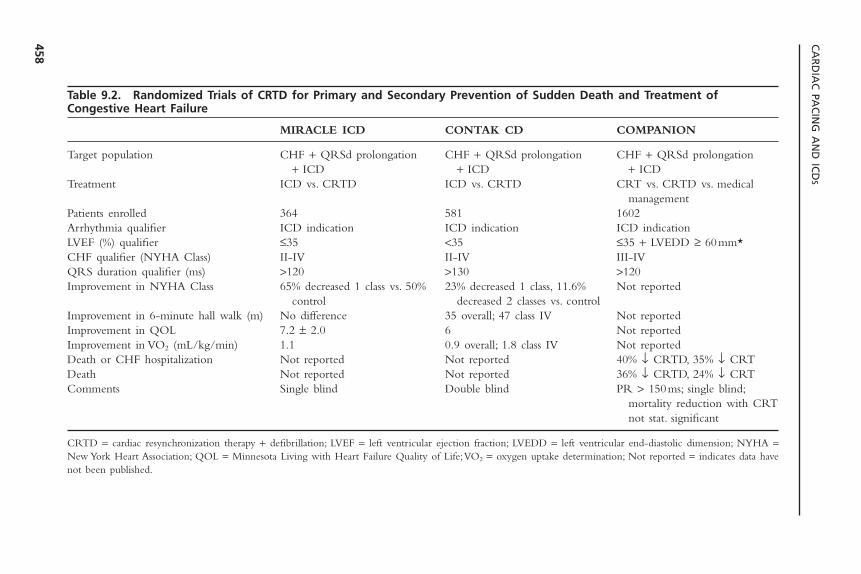
CA
RD
IAC
PAC
ING
AN
D IC
DS
458
Table 9.2. Randomized Trials of CRTD for Primary and Secondary Prevention of Sudden Death and Treatment ofCongestive Heart Failure
MIRACLE ICD CONTAK CD COMPANION
Target population CHF + QRSd prolongation CHF + QRSd prolongation CHF + QRSd prolongation + ICD + ICD + ICD
Treatment ICD vs. CRTD ICD vs. CRTD CRT vs. CRTD vs. medical management
Patients enrolled 364 581 1602Arrhythmia qualifier ICD indication ICD indication ICD indicationLVEF (%) qualifier £35 <35 £35 + LVEDD ≥ 60mm*CHF qualifier (NYHA Class) II-IV II-IV III-IVQRS duration qualifier (ms) >120 >130 >120Improvement in NYHA Class 65% decreased 1 class vs. 50% 23% decreased 1 class, 11.6% Not reported
control decreased 2 classes vs. controlImprovement in 6-minute hall walk (m) No difference 35 overall; 47 class IV Not reportedImprovement in QOL 7.2 ± 2.0 6 Not reportedImprovement in VO2 (mL/kg/min) 1.1 0.9 overall; 1.8 class IV Not reportedDeath or CHF hospitalization Not reported Not reported 40% Ø CRTD, 35% Ø CRTDeath Not reported Not reported 36% Ø CRTD, 24% Ø CRTComments Single blind Double blind PR > 150ms; single blind;
mortality reduction with CRT not stat. significant
CRTD = cardiac resynchronization therapy + defibrillation; LVEF = left ventricular ejection fraction; LVEDD = left ventricular end-diastolic dimension; NYHA =New York Heart Association; QOL = Minnesota Living with Heart Failure Quality of Life;VO2 = oxygen uptake determination; Not reported = indicates data havenot been published.
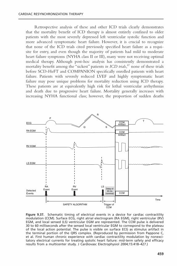
Retrospective analysis of these and other ICD trials clearly demonstratesthat the mortality benefit of ICD therapy is almost entirely confined to olderpatients with the most severely depressed left ventricular systolic function andmore advanced symptomatic heart failure. However, it is crucial to recognizethat none of the ICD trials cited previously specified heart failure as a requi-site for entry, and even though the majority of patients had mild to moderateheart failure symptoms (NYHA class II or III), many were not receiving optimalmedical therapy. Although post-hoc analysis has consistently demonstrated amortality benefit among the “sickest” patients in ICD trials,87 none of these trialsbefore SCD-HeFT and COMPANION specifically enrolled patients with heartfailure. Patients with severely reduced LVEF and highly symptomatic heartfailure may pose unique problems for mortality reduction using ICD therapy.These patients are at equivalently high risk for lethal ventricular arrhythmiasand death due to progressive heart failure. Mortality generally increases withincreasing NYHA functional class; however, the proportion of sudden deaths
CARDIAC RESYNCHRONIZATION THERAPY
459
ECG
P
Q
R
S
TCCM
Artifact
CCM
CCMArtifact
RA EGM
RV EGM
LS EGM
Detected Events
RAEvent
RVEvent
LS
Time
Trigger of CCM
SAFETY ALGORITHM
Delay of 30 ms
(nominal)
Figure 9.37. Schematic timing of electrical events in a device for cardiac contractilitymodulation (CCM). Surface ECG, right atrial electrogram (RA EGM), right ventricular (RV)EGM, and local sensed (LS) ventricular EGM are represented. The CCM pulse is delivered30 to 60 milliseconds after the sensed local ventricular EGM to correspond to the plateauof the local action potential. The pulse is visible on surface ECG as stimulus artifact inthe terminal portion of the QRS complex. (Reproduced by permission from Pappone C,et al. First human chronic experience with cardiac contractility modulation by nonexci-tatory electrical currents for treating systolic heart failure: mid-term safety and efficacyresults from a multicenter study. J Cardiovasc Electrophysiol 2004;15:418–427.)
declines from 50% to 80% among patients with class II symptoms to 5% to 30%among patients with class IV symptoms.88,89 Furthermore, sudden bradyarrhyth-mic death in advanced heart failure90 may occur spontaneously or after suc-cessful termination of VT/VF “storms” in ICD patients (“cardiac annihilation”)91
and further diminish the mortality benefit of ICD therapy.
NON-EXCITATORY CARDIAC CONTRACTILITY MODULATIONCardiac contractility modulation is an evolving device based therapy for heartfailure that does not rely upon the presence of ventricular dyssynchrony for a therapeutic effect. Using standard pacing leads and an implantable pulse gen-erator, non-excitatory electrical stimuli are delivered to the right ventricularmyocardium 30 to 60 milliseconds after the sensed local electrogram (Fig. 9.37).The pulse is biphasic with a duration of 20 to 40 milliseconds and amplitudeup to 10 V. Because this stimulus is delivered during ventricular refractoriness itdoes not participate in the electrical excitation of the ventricle. Instead, thisstimulus prolongs the local action potential duration thereby enhancing the sar-colemmal calcium transient. This in turn increases cardiac contractility. A sig-nificant inotropic effect has been demonstrated in animal and human studies.92,93
In patients with the device implanted for 32 weeks, significant improvementsin ejection fraction, exercise time, and quality of life were demonstrated.93 Atthe time of this writing, this therapy is beginning clinical trials in the UnitedStates.The benefits of this therapy as an alternative or adjunct to cardiac resyn-chronization therapy are unknown.
REFERENCES1. Schocken DD, Arrieta MI, leaverton PE, Ross EA. Prevalence and mortality of con-
gestive heart failure in the United States. J Am Coll Cardiol 1992;20:301–306.2. Ho KKL, Anderson KM, Kannel WB, et al. Survival after the onset of congestive
heart failure in the Framingham Heart Study subjects. Circulation 1993;88:107–115.
3. Massie BM, Shah NB. Evolving trends in the epidemiologic factors of heart failure.Am Heart J 1997;133:703–712.
4. Kannel WB, Plehn JF, Cupples A. Cardiac failure and sudden death in the Fram-ingham study. Am Heart J 1988;115:869–875.
5. Auricchio A, Abraham WT. Cardiac resynchronization therapy: current state of theart. Cost versus benefit. Circulation 2004;109:300–307.
6. Leclerc C, Kass DA. Retiming the failing heart: principles and current clinical statusof cardiac resynchronization. J Am Coll Cardiol 2002;39:194–201.
7. Wiggers C.The muscular reactions of the mammalian ventricles to artificial surfacestimuli. Am J Physiol 1925;73:346–378.
8. Schlant RC. Idioventricular kick. Circulation 1966;33 (Suppl III):III–209.9. Gottipaty VK, Krelis SP, Lu F, et al. The resting electrocardiogram provides a sensi-
tive and inexpensive marker of prognosis in patients with chronic congestive heartfailure. J Am Coll Cardiol 1999;33:145A. Abstract.
CARDIAC PACING AND ICDS
460
10. Baldasseroni S, Opasich C, Gorinii M, et al. Left bundle branch block is associatedwith increased 1-year sudden death and total mortality rate in 5517 outpatients withcongestive heart failure: a report from the Italian Network on Congestive HeartFailure. Am Heart J 2002;143:398–405.
11. Grines CL, Boshore TW, Boudoulas H, et al. Functional abnormalities in isolatedleft bundle branch block: the effect of interventricular asynchrony. Circulation1989;79:845–853.
12. Leclerq C, Faris O, Runin R, et al. Systolic improvement and mechanical resyn-chronization does not require electrical synchrony in the dilated failing heart withleft bundle–branch block. Circulation 2002;106:1760–1763.
13. Verbeek XA,Vernooy K, Peschar M. Intra-ventricular resynchronization for optimalleft ventricular function during pacing in experimental left bundle branch block. JAm Coll Cardiol 2003;42:558–567.
14. Prinzen FW, Hunter WC, Wyman BT, et al. Mapping of regional myocardial strainand work during ventricular pacing: experimental study using magnetic resonanceimaging tagging. J Am Coll Cardiol 1999;33:1735–1742.
15. Prinzen FW, Augustijn CH, Arts T, Allessi MA, Reneman RS. Redistribution ofmyocardial fiber strain and blood flow by asynchronous activation. Am J Physiol1990(259):H300–308.
16. Spragg DD, Leclercq C, Loghmani M, et al. Regional alterations in protein expres-sion in the dyssynchronous failing heart. Circulation 2003;108:929–932.
17. Prinzen FW, Cheriex EC, Delhaas T, et al. Asymmetric thickness of the left ven-tricular wall resulting from asynchronous electric activation: a study in dogs withventricular pacing and in patients with left bundle branch block. Am Heart J1995;130:1045–1053.
18. Breithardt OA, Sinha AM, Schwammenthal E, et al. Acute effects of cardiac resyn-chronization therapy on functional mitral regurgitation in advanced systolic heartfailure. J Am Coll Cardiol 2003;203:765–770.
19. Auricchio A, Fantoni C, Regoli F, et al. Characterization of left ventricular activa-tion in patients with heart failure and left bundle branch block. Circulation (inpress).
20. de Teresa E, Chamorro JL, Pulpon LA, et al. An even more physiologic pacing.Changing the sequence of activation. In: Steinbech K GD, Laskovics A, et al., eds.Cardiac Pacing. Proceedings of the VIIth World Symposium on Cardiac Pacing,1984. Darmstadt, Germany: Steinkoopff Verlag; 1984:395–400.
21. Cazeau S, Ritter P, Bakdach S, et al. Four chamber pacing in dilated cardiomyopa-thy. Pacing Clin Electrophysiol 1994;17:1974–1979.
22. Auricchio A, Stellbrink C, Block M, et al. Effect of pacing chamber and atrioventricular delay on acute systolic function of paced patients with congestiveheart failure. The Pacing Therapies for Congestive Heart Failure Study Group. TheGuidant Congestive Heart Failure Research Group. Circulation 1999;99(23):2993–3001.
23. Nelson GS, Curry CW, Wyman BT, et al. Predictors of systolic augmentation fromleft ventricular preexcitation in patients with dilated cardiomyopathy and intraven-tricular conduction delay. Circulation 2000;101(23):2703–2709.
24. Kerwin WF, Botvinick EH, O’Connell JW, et al.Ventricular contraction abnormal-ities in dilated cardiomyopathy: effect of biventricular pacing to correct interven-tricular dyssynchrony. J Am Coll Cardiol 2000;35:1221–1227.
CARDIAC RESYNCHRONIZATION THERAPY
461

25. Nelson GS, Berger RD, Fetics BJ, et al. Left ventricular or biventricular pacing improves cardiac function at diminished energy cost in patients with dilated cardiomyopathy and left bundle branch block. Circulation 2000;105:3053–3059.
26. St John Sutton MG, Plappert T,Abraham WT, et al, for the MIRACLE Study Group.Effect of cardiac resynchronization therapy on left ventricular size and function inchronic heart failure. Circulation 2003;105(1985–1990).
27. Sogaard P, Egeblad H, Pedersen AK, et al. Sequential versus simultaneous biventric-ular resynchronization for severe heart failure: evaluation by tissue Doppler imaging.Circulation 2002;106:2078–2084.
28. Lau CP, Yu CM, Chau E, et al. Reversal of left ventricular remodeling by syn-chronous biventricular pacing in heart failure. Pacing Clin Electrophysiol 2000;23:1722–1725.
29. Van Oosterhout MFM, Prinzen FW, Arts T, et al. Asynchronous electrical activationinduces asymmetrical hypertrophy of the left ventricular wall. Circulation 1998;98:588–595.
30. Cannan CR, Higano ST, Holmes DR. Pacemaker induced mitral regurgitation: analternative form of pacemaker syndrome. Pacing Clin Electrophysiol 1997;20:735–738.
31. Nunez A, Alberga MT, Cosio FG, et al. Severe mitral regurgitation with right ven-tricular pacing successfully treated with left ventricular pacing. Pacing Clin Elec-trophysiol 2002;25:226–230.
32. Garrigue S, Jais P, Espil G, et al. Comparison of chronic biventricular pacing betweenepicardial and endocardial left ventricular stimulation using Doppler tissue imagingin patients with heart failure. Am J Cardiol 2001;88(8):858–862.
33. Jais P, Takahashi A, Garrigue S, et al. Mid-term follow-up of endocardial biventric-ular pacing. Pacing Clin Electrophysiol 2000;23:1744–1747.
34. Daubert CJ, Ritter P, LeBreton H, et al. Permanent left ventricular pacing withtransvenous leads inserted into the coronary veins. Pacing Clin Electrophysiol1998;21:239–345.
35. Meisel E, Pfeiffer D, Engelmann L, et al. Investigation of coronary venous anatomyby retrograde venography in patients with malignant ventricular tachycardia. Circu-lation 2001;104:442–447.
36. Auricchio A, Stellbrink C, Sack S, et al.The Pacing Therapies for Congestive HeartFailure (PATH-CHF) study: rationale, design, and endpoints of a prospective randomized multicenter study. Am J Cardiol 1999;83(5B):130D–135D.
37. Auricchio A, Klein H, Tockman B, et al. Transvenous biventricular pacing for heartfailure: can the obstacles be overcome? American Journal of Cardiology 1999;83(5B):136D–142D.
38. Butter C, Auricchio A, Stellbrink C, et al. Effect of resynchronization therapy stim-ulation site on the systolic function of heart failure patients. Circulation 2001;104(25):3026–3029.
39. Fauchier L, Marie O, Casset-Senon D, et al. Interventricular and intraventricular dys-synchrony in idiopathic dilated cardiomyopathy: a prognostic study with fourierphase analysis of radionuclide angioscintigraphy. J Am Coll Cardiol 2002;40(11):2031–2033.
40. Auricchio A, Stellbrink C, Sack S, et al. Long-term clinical effect of hemodynami-cally optimized cardiac resynchronization therapy in patients with heart failure andventricular conduction delay. J Am Coll Cardiol 2002;39(12):2026–2033.
CARDIAC PACING AND ICDS
462

41. Garrigue S, Jais P, Espil G, et al. Comparison of chronic biventricular pacing betweenepicardial and endocardial left ventricular stimulation using doppler tissue imagingin patients with heart failure. Am J Cardiol 2001;88:858–862.
42. Abraham WT, Fisher WG, Smith AL, et al. Cardiac resynchronization in chronicheart failure. N Engl J Med 2002;346(24):1845–1853.
43. Young JB, Abraham WT, Smith AL, et al. Combined cardiac resynchronization andimplantable cardioversion defibrillation in advanced chronic heart failure: theMIRACLE ICD Trial. JAMA 2003;289:2685–2694.
44. Bristow MR, Feldman AM, Saxon LA, et al. COMPANION. In: Heart FailureSociety of America, Late Breaking Clinical Trial Presentation; 2003.
45. Blanc JJ, Etienne Y, Gilard M, et al. Evaluation of different ventricular pacing sitesin patients with severe heart failure: results of an acute hemodynamic study. Circu-lation 1997;96:3273–3277.
46. Kass DA, Chen CH, Curry C, et al. Improved left ventricular mechanics from acuteVDD pacing in patients with dilated cardiomyopathy and ventricular conductiondelay. Circulation 1999;99(12):1567–1573.
47. Touiza A, Etienne Y, Gilard M, et al. Long-term left ventricular pacing: assessmentand comparison with biventricular pacing in patients with severe congestive heartfailure. J Am Coll Cardiol 2001;38:1966–1970.
48. Blanc JJ, Bertault–Valls V, Fatemi M, et al. Long-term benefits of left univentricularpacing in patients with congestive heart failure. Circulation 2004; In press.
49. Moss AJ, Hall WJ, Cannom DS, et al. Improved survival with an implanted defi-brillator in patients with coronary disease at high risk for ventricular arrhythmia. NEngl J Med 1996;335:1993–1940.
50. Moss AJ, Zareba W, Hall WJ, et al. Prophylactic implantation of a defibrillator inpatients with myocardial infarction and reduced ejection fraction. N Engl J Med2002;346(12):877–883.
51. Buxton AE, Lee KL, Fisher JD, et al.A randomized study of the prevention of suddendeath among patients with coronary artery disease. N Engl J Med 1999;341:1882–1890.
52. Bardy GH. The Sudden Cardiac Death in Heart Failure Trial (SCD-HeFT). In:Late–Breaking Clinical Trials, American College of Cardiology; 2004.
53. Butter C, Meisel E, Engelmann L, et al. Human experience with transvenous biven-tricular defibrillation using an electrode in a left ventricular vein. Pacing and ClinElectrophysiol 2002;25(3):324–331.
54. Auricchio A, Kramer A, Spinelli J, et al. Can the optimum dosage of resynchro-nization therapy be derived from the intracardiac electrogram? J Am Coll Cardiol2002;39:124. Abstract.
55. Reuter R, Garrigue S, Barold SS, et al. Comparisons of characteristics in respon-ders versus nonresponders with biventricular pacing for drug-resistant congestiveheart failure. Am J Cardiol 2002;89:346–350.
56. Bax JJ, Mohoek SG, Marwick TJ, et al. Left ventricular dyssynchrony predicts benefitof cardiac resynchronization therapy in patients with end-stage heart failure beforepacemaker implantation. Am J Cardiol 2003;92:1238–1240.
57. Pitzalis MV, Iacoviello M, Romito R, et al. Cardiac resynchronization therapy tai-lored by echocardiographic evaluation of ventricular asynchrony. J Am Coll Cardiol2002;40:1615–1622.
58. Kerckhoffs RC, Bovendeerd PH, Kotte JC, et al. Homogeneity of cardiac contrac-tion despite physiological asynchrony of depolarization: a model study. Ann BiomedEng 2003;31:536–547.
CARDIAC RESYNCHRONIZATION THERAPY
463

59. Kadhiresan V,Vogt J, Auricchio A, et al. Sensitivity and specificity of QRS durationto predict acute benefit in heart failure patients with cardiac resynchronization.Pacing Clin Electrophysiol 2000;23(II):555. Abstract.
60. D’Hooge J, Heimdal A, Jamal F, et al. Regional strain and strain rate measurementsby cardiac ultrasound: principles, implementation and limitations. Eur J Echocar-diography 2000;1:154–170.
61. Breithardt OA, Stellbrink C, Herbots L, et al. Cardiac resynchronization therapy canreverse abnormal myocardial strain distribution in patients with heart failure and leftbundle branch block. J Am Coll Cardiol 2003;42:486–494.
62. Sogaard P, Egeblad H, Kim W, et al.Tissue Doppler imaging predicts improved sys-tolic performance and reversed left ventricular remodeling during cardiac resyn-chronization therapy. J Am Coll Cardiol 2002;40:723–730.
63. Baxx JJ, Yu C-M, Lin H, et al. Comparison of acute changes in left ventricularvolume, systolic and diastolic functions, and intraventricular synchronicity afterbiventricular pacing and right ventricular pacing for congestive heart failure. AmHeart J 2003;145:G1–G7.
64. Bax JJ, Molhoek SG, Marwick TH, et al. Usefulness of myocardial tissue Dopplerechocardiography to evaluate left ventricular dyssynchrony before and after biven-tricular pacing in patients with idiopathic dilated cardiomyopathy. Am J Cardiol2003;91:94–97.
65. Yu C-M, Fung W-H, Lin H, et al. Predictors of left ventricular reverse remodelingafter cardiac resynchronization therapy for heart failure secondary to idiopathicdilated or ischemic cardiomyopathy. Am J Cardiol 2002;91:684–688.
66. Auricchio A, Stellbrink C, Sack S, et al. Long-term benefit as a result of pacingresynchronization in congestive heart failure: results of the PATH-CHF Trial. Cir-culation 2000;102:II–693A.
67. Linde C, Leclerc C, Rex S, et al. Long-term benefits of biventricular pacing in con-gestive heart failure: Results from the Multisite Stimulation in Cardiomyopathy(MUSTIC) Study. J Am Coll Cardiol 2002;40:111–118.
68. Linde C, Braunschweig F, Gadler F, Bailleul C, Daubert JC. Long-term improve-ment in quality of life by biventricular pacing in patients with chronic heart failure:results from the MUSTIC Study. Am J Cardiol 2003;91:1090–1095.
69. Aranda JM, Curtis AB, Conti JB, Stejskal-Peterson S. Do heart failure patients withright bundle branch block benefit from cardiac resynchronization therapy? Analysisof the MIRACLE Study. J Am Coll Cardiol 2002;39:96A. Abstract.
70. Yu C-M,Yang H, Lau C-P, et al. Regional left ventricular mechanical asynchronyin patients with heart disease and normal QRS duration. Pacing Clin Electrophys-iol 2003;26:562–570.
71. Achilli A, Sassara M, Ficili S, et al. Long term effectiveness of cardiac resynchro-nization therapy in patients with refractory heart failure and “narrow” QRS dura-tion. J Am Coll Cardiol 2003;42:2117–2124.
72. Kass DM. Predicting cardiac resynchronization response by QRS duration. J AmColl Cardiol 2003;42:2125–2127.
73. Gaspirini M, Mantica M, Galimberti P, et al. Beneficial effects of biventricular pacingin patients with a “narrow” QRS duration. Pacing Clin Electrophysiol 2003;26:169–174.
74. Sweeney MO, Hellkamp AS, Ellenbogen KA, et al. Adverse effect of ventricularpacing on heart failure and atrial fibrillation among patients with normal baseline
CARDIAC PACING AND ICDS
464

QRS duration in a clinical trial of pacemaker therapy for sinus node dysfunction.Circulation 2003;23:2932–2937.
75. The DAVID Trial Investigators. Dual-chamber pacing or ventricular backup pacingin patients with an implantable defibrillator: the Dual Chamber and VVI ImplantableDefibrillator (DAVID) Trial. JAMA 2002;288(24):3115–3123.
76. Peschar M, de Swart H, Michels KJ, Reneman RS, Prinzen FW. Left ventricularseptal and apex pacing for optimal pump function in canine hearts. J Am CollCardiol 2003;41(7):1218–1226.
77. Cazeau S, Leclerlq C, Lavergne T, et al. Effects of multisite biventricular pacing inpatients with heart failure and intraventricular conduction delay. N Engl J Med2001;344:873–880.
78. Bradley DJ, Bradley EA, Baughman KL, et al. Cardiac resynchronization and deathfrom progressive heart failure: a meta-analysis of randomized controlled trials. JAMA2003;289:730–740.
79. Gillum RF. Sudden coronary death in the United States. Circulation 1989;79:756–765.
80. Moss AJ. Sudden cardiac death and national health. Pacing Clin Electrophysiol1993;16:2190–2191.
81. The Antiarrhythmics versus Implantable Defibrillator (AVID) Investigators. A com-parison of antiarrhythmic-drug therapy with implantable defibrillators in patientsresuscitated from near-fatal ventricular arrhythmias. N Engl J Med 1997;337:1576–1583.
82. Kuck KH, Cappato R, Siebels J, Ruppel F, for the CASH Investigators. Random-ized comparison of antiarrhythmia drug therapy with implantable defibrillators inpatients resuscitated from cardiac arrest: the Cardiac Arrest Study Hamburg (CASH).Circulation 2000;102:748–754.
83. Connolly SJ, Gent M, Roberts RS, et al. Canadian implantable defibrillator study(CIDS): a randomized trial of the implantable cardioverter defibrillator against amio-darone. Circulation 2000;101:1297–1302.
84. Shamim W, Francis DP,Yousufuddin M, et al. Intra-ventricular conduction delay: aprognostic marker in congestive heart failure. Int J Cardiol 1999;70:171–178.
85. Gerber TC, Nishimura R, Holmes DR, et al. Left ventricular and biventricularpacing in congestive heart failure. Mayo Clin Proc 2001;706:803–812.
86. Higgins SL, Hummel JD, Niazi IK, et al. Cardiac resynchronization therapy for thetreatment of heart failure and intraventricular conduction delay and malignant ven-tricular tachyarrhythmia. J Am Coll Cardiol 2003;42:1454–1459.
87. Moss AJ. Implantable cardioverter defibrillator therapy: the sickest patients benefitthe most. Circulation 2000;101:1638–1640.
88. MERIT-HF Study Group. Effect of metoprolol CR/XL in chronic heart failure:metoprolol CR/XL randomized intervention trial in congestive heart failure(MERIT-HF). Lancet 1999;353:2001–2007.
89. Uretsky B, Sheahan G. Primary prevention of sudden cardiac death in heart failure:will the result be shocking? J Am Coll Cardiol 1997;30:1589–1597.
90. Luu M, Stevenson WG, Saxon LA, Stevenson LW. Diverse mechanisms of unex-pected cardiac arrest in heart failure. Circulation 1989;80:1675–1680.
91. Mitchell LB, Pineda EA, Titus JL, Bartosch PM, Benditt DG. Sudden death inpatients with implantable cardioverter defibrillators: importance of post-shockelectromechanical dissociation. J Am Coll Cardiol 2002;39(8):1323–1328.
CARDIAC RESYNCHRONIZATION THERAPY
465

92. Mohri S, He KL, Dickstein M, et al. Cardiac contractility modulation by electricalcurrents applied during the refractory period. Am J Physiol Heart Circ Physiol2002;282:H1642–H1647.
93. Pappone C,Augello G, Rosanio S, et al. First human chronic experience with cardiaccontractility modulation by nonexcitatory electrical currents for treating systolicheart failure: mid-term safety and efficacy results from a multicenter study. J Car-diovasc Electrophysiol 2004;15:418–427.
CARDIAC PACING AND ICDS
466
467
The implantable cardioverter-defibrillator (ICD) is the treatment of choice foraborted sudden cardiac death and sustained ventricular arrhythmias in theabsence of acute myocardial infarction or reversible causes. Patients with thesedevices need regular follow-up by a physician knowledgeable of ICDs to ensureappropriate functioning and avoid potential problems. Further, the physicianmust be able to investigate and solve any problems that may arise with the ICD.
FOLLOW-UP AFTER IMPLANTABLE CARDIOVERTER-DEFIBRILLATOR PLACEMENT
After implanting the device and before discharging the patient from the hospi-tal, the implanting physician should observe the following procedures:
1. Inspect the ICD site for evidence of hematoma or infection.2. Counsel the patient about keeping the ICD site clean and dry for 1 week
as well as avoiding raising the arm ipsilateral to the ICD above the shoulderor reaching for the horizon for 2 to 4 weeks.
3. Interrogate the ICD and perform a noninvasive check of lead resistances aswell as lead sensing and pacing thresholds.
4. Obtain chest radiographs in the anteroposterior and lateral views to ascer-tain appropriate lead positions.
5. Discuss driving, activity, and occupational restrictions appropriate for thepatient’s condition. Most states have mandatory driving restrictions for 6 to12 months following a syncopal event due to ventricular arrhythmias.1
In addition, some devices emit audible alert tones to indicate battery deple-tion, high lead impedances or prolonged charge times. These tones should bedemonstrated to the patient and their importance emphasized.
The ICD patient should be seen again at 2 to 4 weeks after the implan-tation surgery to ascertain whether the wound is healing appropriately.The ICD
10ICD Follow-up and
TroubleshootingHenry F. Clemo and Mark A. Wood
pocket should be carefully examined for evidence of infection.The ICD systemshould be checked as outlined below to ensure that the lead is stable and thedevice is functioning. Patients should be seen every 3 to 6 months thereafteruntil the device approaches elective replacement indicators, at which time morefrequent follow-up assessments are warranted.
ROUTINE FOLLOW-UPThe purpose of subsequent follow-up visits is to assess the patient’s condition,check the stability and performance of the ICD system and the adequacy ofprogrammed therapies, provide patient education, and investigate potentialdevice malfunctions.
History and Physical ExaminationThe history and physical examination can be invaluable for understanding theperformance of a patient’s ICD. The patient should be asked about the occur-rence of shocks or syncope. In particular, conditions such as congestive heartfailure and cardiac ischemia, which may precipitate ventricular tachyarrhythmias,should be evaluated. Conditions such as chronic obstructive pulmonary disease,infection, anemia, and dehydration that can precipitate supraventricular tachy-arrhythmias and inappropriate shocks should be investigated.The patient shouldbe questioned as to whether particular body positions have triggered ICDtherapy. A drug history should be obtained at each visit, because some medica-tions could change pacing, sensing, and defibrillation thresholds; others couldcause electrolyte imbalances that may interfere with appropriate ICD function.2
Furthermore, patients who have congestive heart failure or recurrent cardiacischemia should be placed on effective doses of beta blockers, angiotensin-converting enzyme inhibitors, and “statins,” all of which reduce the incidenceof sudden cardiac death and possibly the frequency of delivered ICD therapy.3–5
The patient should also be examined for ICD infection or erosion. Early detec-tion of impending device erosion can prevent the possibility of catastrophic ICDsystem infection.
Device InterrogationAt each visit, information retrieved from the device using an ICD programmershould be examined carefully in a systematic fashion.
Programmed Parameters: Programmed parameters include detection and treat-ment algorithms for ventricular tachyarrhythmias, therapies for bradyarrhyth-mias, and various alert settings. Review of these parameters may reveal erroneousprogramming that can potentially result in inappropriate or suppressed ICDtherapy. For example, failure to program a VT zone could prevent delivery ofeffective therapy for undetected ventricular tachycardia. On the other hand,failure to use supraventricular tachyarrhythmia (SVT) discrimination schemescould allow SVTs such as atrial fibrillation to trigger inappropriate ICD therapy.
CARDIAC PACING AND ICDS
468
Occasionally, patients who have ICD therapies suspended when they undergosurgery are left unprotected when these therapies are not reactivated after com-pletion of their procedures.
System Data: System data include lead impedances, battery voltage, capacitorcharge time, and defibrillation circuit resistance. Initial examination of this datacan quickly reveal potential problems with the ICD system including batterydepletion (low battery voltage or prolonged charge time), faulty capacitor func-tion (prolonged charge time), lead insulation failure (low impedance), or leadconductor fracture (high impedance).These values should be compared to infor-mation recorded from previous visits and to the guidelines for the specific ICDmodel. In particular, lithium–silver–vanadium oxide batteries are used in ICDs.These batteries have unusual voltage discharge characteristics and approach end-of-life voltage in a less predictable fashion than pacemaker batteries.
Elective replacement indicators for ICDs are based on battery voltage withor without charge time criteria specific for each model of ICD. The chargetimes reflect the time required to charge the capacitor to high voltages. Pro-longed charge times may indicate battery depletion, capacitor or componentmalfunction, or excessive times between capacitor reformation.The reformationprocess restores the insulating dielectric between the capacitor plates needed foroptimal capacitor function.This is usually performed automatically by the deviceat 3- to 6-month intervals. When the ICD battery voltage is approaching elec-tive replacement status, the patient should be observed on a more frequent basis(i.e., monthly or bimonthly) to allow for timely ICD generator replacement.
Event Logs: Event logs include ventricular and supraventricular tachyarrhythmiaepisodes/electrograms and therapies, bradyarrhythmia information, and systemcomponent alerts. Obviously, each episode of ventricular tachycardia (VT), ven-tricular fibrillation (VF), and SVT should be reviewed carefully to ensure thatdetection was appropriate and that the therapy was effective. Several companieshave introduced the ability to remotely interrogate ICDs using monitoring sta-tions based in the patient’s home. The retrieved data from the ICD are trans-mitted by telephone line to a secure server that may be accessed by authorizedhealthcare providers over the Internet (Fig. 10.1). This information may allowphysicians to assess the device programming, activity, and performance withoutthe patient leaving home.
System Component TestingThe system components that require intermittent testing include the sensingand pacing thresholds. These should be determined at each visit. Occasionally,defibrillation threshold testing may need to be done.
Sensing: Sensing of intrinsic intracardiac signals by atrial and ventricular leads mustbe determined to make sure that atrial and ventricular tachyarrhythmias arebeing reliably detected. Some ICDs include a semiautomated check of sensing,
ICD FOLLOW-UP AND TROUBLESHOOTING
469
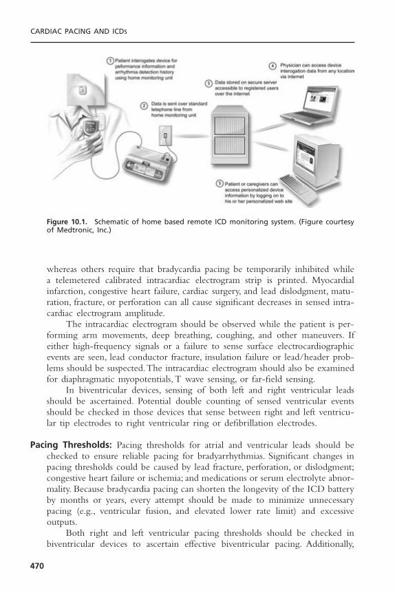
whereas others require that bradycardia pacing be temporarily inhibited whilea telemetered calibrated intracardiac electrogram strip is printed. Myocardialinfarction, congestive heart failure, cardiac surgery, and lead dislodgment, matu-ration, fracture, or perforation can all cause significant decreases in sensed intra-cardiac electrogram amplitude.
The intracardiac electrogram should be observed while the patient is per-forming arm movements, deep breathing, coughing, and other maneuvers. Ifeither high-frequency signals or a failure to sense surface electrocardiographicevents are seen, lead conductor fracture, insulation failure or lead/header prob-lems should be suspected.The intracardiac electrogram should also be examinedfor diaphragmatic myopotentials, T wave sensing, or far-field sensing.
In biventricular devices, sensing of both left and right ventricular leadsshould be ascertained. Potential double counting of sensed ventricular eventsshould be checked in those devices that sense between right and left ventricu-lar tip electrodes to right ventricular ring or defibrillation electrodes.
Pacing Thresholds: Pacing thresholds for atrial and ventricular leads should bechecked to ensure reliable pacing for bradyarrhythmias. Significant changes inpacing thresholds could be caused by lead fracture, perforation, or dislodgment;congestive heart failure or ischemia; and medications or serum electrolyte abnor-mality. Because bradycardia pacing can shorten the longevity of the ICD batteryby months or years, every attempt should be made to minimize unnecessarypacing (e.g., ventricular fusion, and elevated lower rate limit) and excessiveoutputs.
Both right and left ventricular pacing thresholds should be checked inbiventricular devices to ascertain effective biventricular pacing. Additionally,
CARDIAC PACING AND ICDS
470
Figure 10.1. Schematic of home based remote ICD monitoring system. (Figure courtesyof Medtronic, Inc.)
diaphragmatic and chest wall pacing should be checked at maximal left ven-tricular voltage and pulse duration.
Defibrillation Threshold Testing: Defibrillation threshold (DFT) testing mayhave to be repeated using the noninvasive electrophysiology study capability ofthe ICD. Situations in which repeat DFT testing should be done include addi-tion of a new antiarrhythmic drug to the patient’s treatment program or cardiacevents such as myocardial infarction or cardiac surgery. All of these conditionsmay potentially change the rate and morphology of ventricular tachyarrhyth-mias or the minimal energy required for defibrillation (DFT). Testing is alsowarranted to evaluate failed therapies or to assess sensing during ventriculartachycardia or ventricular fibrillation. Routine yearly defibrillation testing hasbeen advocated by some, but the yield for significant problems has been low.6,7
Implantable Cardioverter-Defibrillator ProgrammingProgramming of ICDs can be complex and frustrating. The successful pro-gramming of an ICD depends on a good understanding of a particular patient’sarrhythmias and the symptoms from those arrhythmias, as well as the underly-ing cardiac pathophysiology and the patient’s medications. In addition, a thor-ough knowledge of the capabilities of the patient’s ICD is essential.The variousparameters that may be programmed are shown in Table 10.1.
Ventricular Tachyarrhythmia Detection: Most devices allow for multiple zonesof ventricular tachyarrhythmia detection based on heart rate. Often, a zone isprogrammed for slower, relatively well-tolerated ventricular tachycardia (VTzone), and another zone is programmed for faster, hemodynamically unstableventricular tachycardia or fibrillation (VF zone). For example, a VT zone maybe set for rates of 160 to 200 beats per minute (bpm) with the VF zone forrates over 200bpm.The rate limits for these zones are usually set 10bpm slowerthan the documented ventricular arrhythmia rate to ensure reliable detection.Ventricular tachycardia induced by electrophysiologic testing is often much fasterthan the patient’s spontaneous arrhythmia and is not usually an accurate guideto setting the rate limits.
The ventricular sensitivity must allow for the detection of very low ampli-tude ventricular fibrillation signals and is typically set to 0.3mV, or more sen-sitive settings. Criteria for the number of beats or the time duration above thetachycardia rate in each zone must also be programmed to complete the detec-tion algorithm. An example of a ventricular tachyarrhythmia detection schemeas programmed in a dual-chamber ICD is shown in Figure 10.2.
In the VT zone, various enhancements are available to decrease the risk ofsupraventricular tachyarrhythmias triggering therapy. In single-chamber ICDs,stability, suddenness of onset, and duration of arrhythmia may be used to increasethe specificity for ventricular arrhythmias. These features are described furtherin Table 10.2. Some defibrillators offer the option of using electrogram dura-tion or morphology to aid in discriminating between supraventricular
ICD FOLLOW-UP AND TROUBLESHOOTING
471
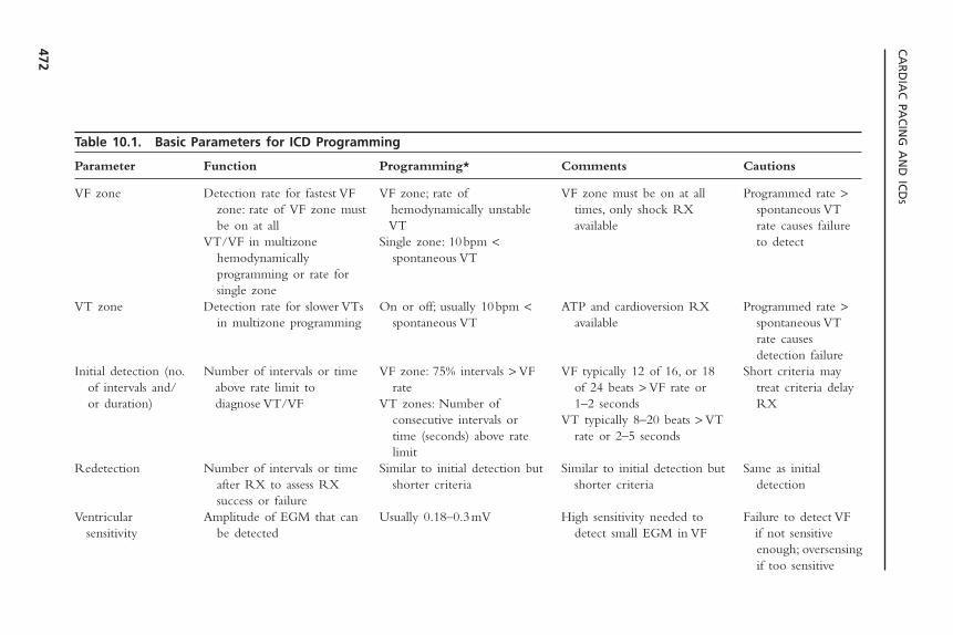
CA
RD
IAC
PAC
ING
AN
D IC
DS
472
Table 10.1. Basic Parameters for ICD Programming
Parameter Function Programming* Comments Cautions
VF zone Detection rate for fastest VF VF zone; rate of VF zone must be on at all Programmed rate >zone: rate of VF zone must hemodynamically unstable times, only shock RX spontaneous VT be on at all VT available rate causes failure
VT/VF in multizone Single zone: 10bpm < to detecthemodynamically spontaneous VTprogramming or rate for single zone
VT zone Detection rate for slower VTs On or off; usually 10bpm < ATP and cardioversion RX Programmed rate >in multizone programming spontaneous VT available spontaneous VT
rate causes detection failure
Initial detection (no. Number of intervals or time VF zone: 75% intervals > VF VF typically 12 of 16, or 18 Short criteria mayof intervals and/ above rate limit to rate of 24 beats > VF rate or treat criteria delay or duration) diagnose VT/VF VT zones: Number of 1–2 seconds RX
consecutive intervals or VT typically 8–20 beats > VT time (seconds) above rate rate or 2–5 secondslimit
Redetection Number of intervals or time Similar to initial detection but Similar to initial detection but Same as initial after RX to assess RX shorter criteria shorter criteria detectionsuccess or failure
Ventricular Amplitude of EGM that can Usually 0.18–0.3mV High sensitivity needed to Failure to detect VF sensitivity be detected detect small EGM in VF if not sensitive
enough; oversensingif too sensitive
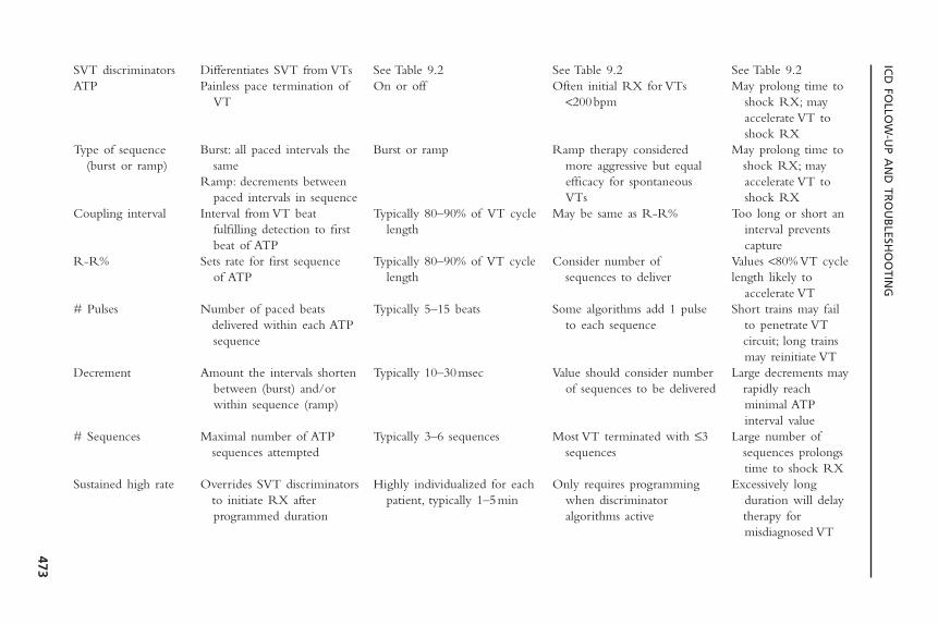
ICD
FOLLO
W-U
P AN
D TR
OU
BLESH
OO
TING
473
SVT discriminators Differentiates SVT from VTs See Table 9.2 See Table 9.2 See Table 9.2ATP Painless pace termination of On or off Often initial RX for VTs May prolong time to
VT <200bpm shock RX; may accelerate VT to shock RX
Type of sequence Burst: all paced intervals the Burst or ramp Ramp therapy considered May prolong time to (burst or ramp) same more aggressive but equal shock RX; may
Ramp: decrements between efficacy for spontaneous accelerate VT to paced intervals in sequence VTs shock RX
Coupling interval Interval from VT beat Typically 80–90% of VT cycle May be same as R-R% Too long or short an fulfilling detection to first length interval prevents beat of ATP capture
R-R% Sets rate for first sequence Typically 80–90% of VT cycle Consider number of Values <80% VT cycleof ATP length sequences to deliver length likely to
accelerate VT# Pulses Number of paced beats Typically 5–15 beats Some algorithms add 1 pulse Short trains may fail
delivered within each ATP to each sequence to penetrate VT sequence circuit; long trains
may reinitiate VTDecrement Amount the intervals shorten Typically 10–30msec Value should consider number Large decrements may
between (burst) and/or of sequences to be delivered rapidly reach within sequence (ramp) minimal ATP
interval value# Sequences Maximal number of ATP Typically 3–6 sequences Most VT terminated with £3 Large number of
sequences attempted sequences sequences prolongs time to shock RX
Sustained high rate Overrides SVT discriminators Highly individualized for each Only requires programming Excessively long to initiate RX after patient, typically 1–5min when discriminator duration will delay programmed duration algorithms active therapy for
misdiagnosed VT
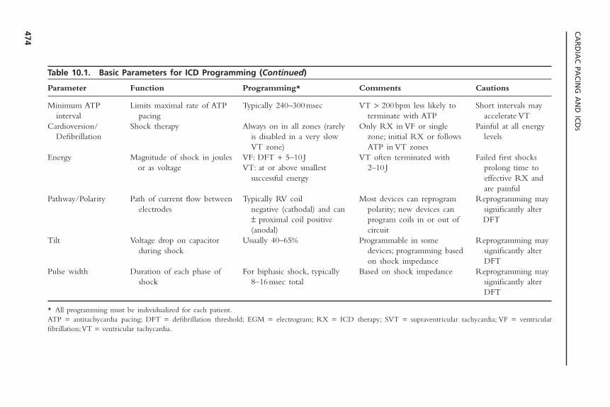
CA
RD
IAC
PAC
ING
AN
D IC
DS
474
Table 10.1. Basic Parameters for ICD Programming (Continued)
Parameter Function Programming* Comments Cautions
Minimum ATP Limits maximal rate of ATP Typically 240–300msec VT > 200bpm less likely to Short intervals may interval pacing terminate with ATP accelerate VT
Cardioversion/ Shock therapy Always on in all zones (rarely Only RX in VF or single Painful at all energy Defibrillation is disabled in a very slow zone; initial RX or follows levels
VT zone) ATP in VT zonesEnergy Magnitude of shock in joules VF: DFT + 5–10 J VT often terminated with Failed first shocks
or as voltage VT: at or above smallest 2–10 J prolong time to successful energy effective RX and
are painfulPathway/Polarity Path of current flow between Typically RV coil Most devices can reprogram Reprogramming may
electrodes negative (cathodal) and can polarity; new devices can significantly alter ± proximal coil positive program coils in or out of DFT(anodal) circuit
Tilt Voltage drop on capacitor Usually 40–65% Programmable in some Reprogramming may during shock devices; programming based significantly alter
on shock impedance DFTPulse width Duration of each phase of For biphasic shock, typically Based on shock impedance Reprogramming may
shock 8–16msec total significantly alter DFT
* All programming must be individualized for each patient.ATP = antitachycardia pacing; DFT = defibrillation threshold; EGM = electrogram; RX = ICD therapy; SVT = supraventricular tachycardia; VF = ventricular fibrillation;VT = ventricular tachycardia.
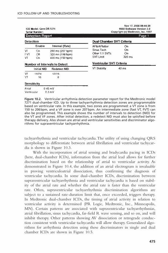
ICD FOLLOW-UP AND TROUBLESHOOTING
475
tachyarrhythmia and ventricular tachycardia.The utility of using changing QRSmorphology to differentiate between atrial fibrillation and ventricular tachycar-dia is shown in Figure 10.3.
With the incorporation of atrial sensing and bradycardia pacing in ICDs(here, dual-chamber ICDs), information from the atrial lead allows for furtherdiscrimination based on the relationship of atrial to ventricular activity. Asdemonstrated in Figure 10.4, the addition of an atrial electrogram is invaluablein proving ventriculoatrial dissociation, thus confirming the diagnosis of ventricular tachycardia. In some dual-chamber ICDs, discrimination betweensupraventricular tachyarrhythmia and ventricular tachycardia is based on stabil-ity of the atrial rate and whether the atrial rate is faster than the ventricularrate. Often, supraventricular tachyarrhythmia discrimination algorithms aresubject to a sustained rate-duration limit that, once exceeded, triggers therapy.In Medtronic dual-chamber ICDs, the timing of atrial activity in relation toventricular activity is determined (PR Logic, Medtronic, Inc., Minneapolis,MN). Certain patterns are associated with supraventricular tachyarrhythmias,atrial fibrillation, sinus tachycardia, far-field R wave sensing, and so on, and willinhibit therapy. Other patterns showing AV dissociation or retrograde conduc-tion consistent with ventricular tachycardia will allow therapy. Generalized algo-rithms for arrhythmia detection using these discriminators in single and dualchamber ICDs are shown in Figure 10.5.
Figure 10.2. Ventricular arrhythmia detection parameter report for the Medtronic model7271 dual-chamber ICD. Up to three tachyarrhythmia detection zones are programmablebased on ventricular rate. In this example, two zones are programmed: a VT zone is from150 to 206bpm, and a VF zone is over 207bpm. An intermediate zone (fast VT, FVT) canalso be programmed. This example shows the number of intervals to detection (NID) forthe VT and VF zones. After initial detection, a redetect NID must also be satisfied beforetherapy delivery. Also shown are atrial and ventricular sensitivities and discriminator algo-rithms for supraventricular tachyarrhythmia.
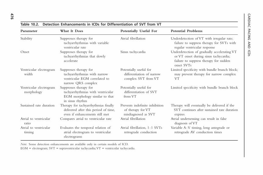
CA
RD
IAC
PAC
ING
AN
D IC
DS
476
Table 10.2. Detection Enhancements in ICDs for Differentiation of SVT from VT
Parameter What It Does Potentially Useful For Potential Problems
Stability Suppresses therapy for Atrial fibrillation Underdetection of VT with irregular rate;tachyarrhythmias with variable failure to suppress therapy for SVTs with ventricular rate regular ventricular response
Onset Suppresses therapy for Sinus tachycardia Underdetection of gradually accelerating VTtachyarrhythmias that slowly or VT onset during sinus tachycardia;accelerate failure to suppress therapy for sudden
onset SVTsVentricular electrogram Suppresses therapy for Potentially useful for Limited specificity with bundle branch block;
width tachyarrhythmias with narrow differentiation of narrow may prevent therapy for narrow complex ventricular EGM correlated to complex SVT from VT VTnarrow QRS complex
Ventricular electrogram Suppresses therapy for Potentially useful for Limited specificity with bundle branch blockmorphology tachyarrhythmias with ventricular differentiation of SVT
EGM morphology similar to that from VTin sinus rhythm
Sustained rate duration Therapy for tachyarrhythmias finally Prevents indefinite inhibition Therapy will eventually be delivered if the delivered after this period of time, of therapy for VT SVT continues after sustained rate duration even if enhancements still met misdiagnosed as SVT expires
Atrial to ventricular Compares atrial to ventricular rate Atrial fibrillation Atrial undersensing can result in false ratio diagnosis of VT
Atrial to ventricular Evaluates the temporal relation of Atrial fibrillation, 1 :1 SVTs Variable A :V timing, long antegrade or timing atrial electrogram to ventricular retrograde conduction retrograde AV conduction times
electrograms
Note: Some detection enhancements are available only in certain models of ICD.EGM = electrogram; SVT = supraventricular tachycardia;VT = ventricular tachycardia.
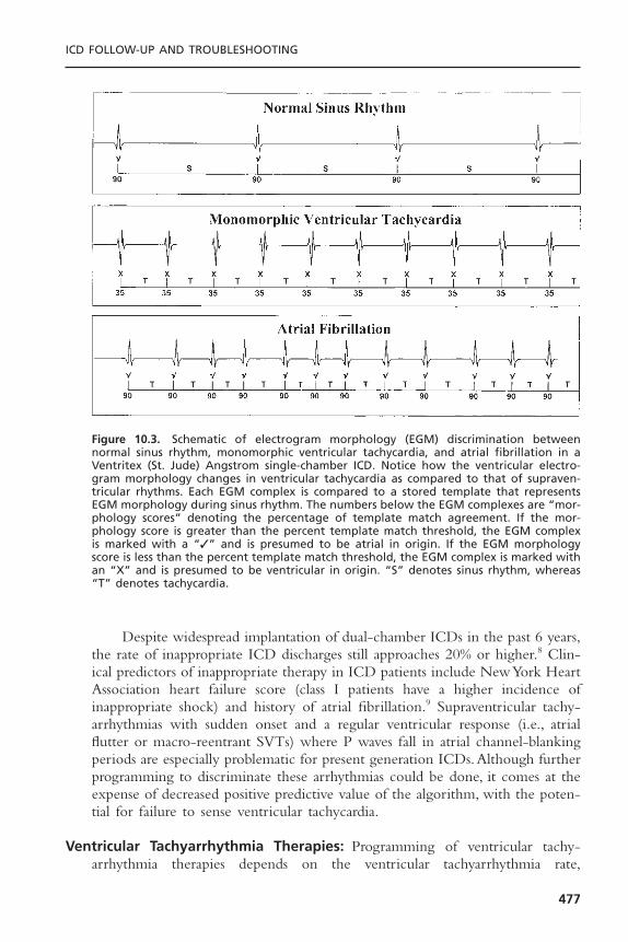
ICD FOLLOW-UP AND TROUBLESHOOTING
477
Figure 10.3. Schematic of electrogram morphology (EGM) discrimination betweennormal sinus rhythm, monomorphic ventricular tachycardia, and atrial fibrillation in aVentritex (St. Jude) Angstrom single-chamber ICD. Notice how the ventricular electro-gram morphology changes in ventricular tachycardia as compared to that of supraven-tricular rhythms. Each EGM complex is compared to a stored template that representsEGM morphology during sinus rhythm. The numbers below the EGM complexes are “mor-phology scores” denoting the percentage of template match agreement. If the mor-phology score is greater than the percent template match threshold, the EGM complexis marked with a “✓” and is presumed to be atrial in origin. If the EGM morphologyscore is less than the percent template match threshold, the EGM complex is marked withan “X” and is presumed to be ventricular in origin. “S” denotes sinus rhythm, whereas“T” denotes tachycardia.
Despite widespread implantation of dual-chamber ICDs in the past 6 years,the rate of inappropriate ICD discharges still approaches 20% or higher.8 Clin-ical predictors of inappropriate therapy in ICD patients include New York HeartAssociation heart failure score (class I patients have a higher incidence of inappropriate shock) and history of atrial fibrillation.9 Supraventricular tachy-arrhythmias with sudden onset and a regular ventricular response (i.e., atrialflutter or macro-reentrant SVTs) where P waves fall in atrial channel-blankingperiods are especially problematic for present generation ICDs.Although furtherprogramming to discriminate these arrhythmias could be done, it comes at theexpense of decreased positive predictive value of the algorithm, with the poten-tial for failure to sense ventricular tachycardia.
Ventricular Tachyarrhythmia Therapies: Programming of ventricular tachy-arrhythmia therapies depends on the ventricular tachyarrhythmia rate,
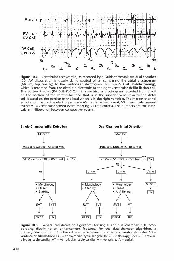
478
Figure 10.4. Ventricular tachycardia, as recorded by a Guidant Ventak AV dual-chamberICD. AV dissociation is clearly demonstrated when comparing the atrial electrogram(Atrium, top tracing) to the ventricular electrogram (RV Tip–RV Coil, middle tracing),which is recorded from the distal tip electrode to the right ventricular defibrillation coil.The bottom tracing (RV Coil–SVC Coil) is a ventricular electrogram recorded from a coilon the portion of the ventricular lead that is in the superior vena cava to the distal coil located on the portion of the lead which is in the right ventricle. The marker channelannotations below the electrograms are AS = atrial sensed event; VS = ventricular sensedevent; VT = ventricular sensed event meeting VT rate criteria. The numbers are the inter-vals in milliseconds between consecutive events.
Single Chamber Initial Detection Dual Chamber Initial Detection
No
Yes
Monitor
Rate and Duration Criteria Met
V < A V = A V > A
VF Zone &/or TCL < SVT limit Rx
SVT VT
RxInhibit
SVT VT
RxInhibit
VT/VF
Rx
• Morphology• Onset• A-V Timing
• Morphology• Stability
No
Yes
Monitor
Rate and Duration Criteria Met
VF Zone &/or TCL < SVT limit Rx
SVT VT
RxInhibit
• Morphology• Onset• Stability
Figure 10.5. Generalized detection algorithms for single- and dual-chamber ICDs incor-porating discrimination enhancement features. For the dual-chamber algorithm, aprimary “decision point” is the difference between the atrial and ventricular rates. VF =ventricular fibrillation; TCL = tachycardia cycle length; Rx = ICD therapy; SVT = supraven-tricular tachycardia; VT = ventricular tachycardia; V = ventricle; A = atrial.
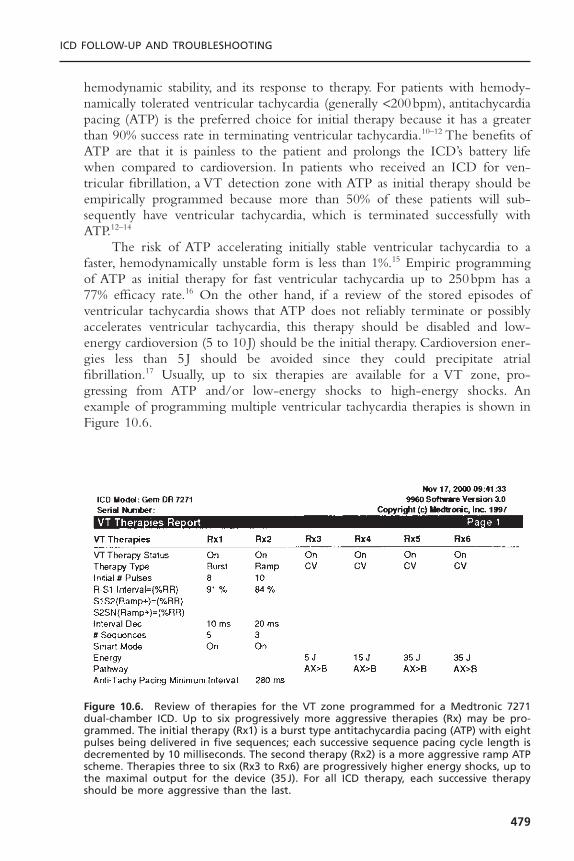
hemodynamic stability, and its response to therapy. For patients with hemody-namically tolerated ventricular tachycardia (generally <200bpm), antitachycardiapacing (ATP) is the preferred choice for initial therapy because it has a greaterthan 90% success rate in terminating ventricular tachycardia.10–12 The benefits ofATP are that it is painless to the patient and prolongs the ICD’s battery lifewhen compared to cardioversion. In patients who received an ICD for ven-tricular fibrillation, a VT detection zone with ATP as initial therapy should beempirically programmed because more than 50% of these patients will sub-sequently have ventricular tachycardia, which is terminated successfully withATP.12–14
The risk of ATP accelerating initially stable ventricular tachycardia to afaster, hemodynamically unstable form is less than 1%.15 Empiric programmingof ATP as initial therapy for fast ventricular tachycardia up to 250bpm has a77% efficacy rate.16 On the other hand, if a review of the stored episodes ofventricular tachycardia shows that ATP does not reliably terminate or possiblyaccelerates ventricular tachycardia, this therapy should be disabled and low-energy cardioversion (5 to 10 J) should be the initial therapy. Cardioversion ener-gies less than 5 J should be avoided since they could precipitate atrialfibrillation.17 Usually, up to six therapies are available for a VT zone, pro-gressing from ATP and/or low-energy shocks to high-energy shocks. Anexample of programming multiple ventricular tachycardia therapies is shown inFigure 10.6.
ICD FOLLOW-UP AND TROUBLESHOOTING
479
Figure 10.6. Review of therapies for the VT zone programmed for a Medtronic 7271dual-chamber ICD. Up to six progressively more aggressive therapies (Rx) may be pro-grammed. The initial therapy (Rx1) is a burst type antitachycardia pacing (ATP) with eightpulses being delivered in five sequences; each successive sequence pacing cycle length isdecremented by 10 milliseconds. The second therapy (Rx2) is a more aggressive ramp ATPscheme. Therapies three to six (Rx3 to Rx6) are progressively higher energy shocks, up tothe maximal output for the device (35J). For all ICD therapy, each successive therapyshould be more aggressive than the last.
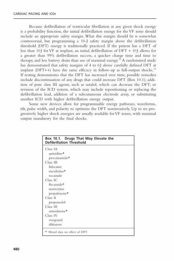
Because defibrillation of ventricular fibrillation at any given shock energyis a probability function, the initial defibrillation energy for the VF zone shouldinclude an appropriate safety margin. What this margin should be is somewhatcontroversial, but programming a 10-J safety margin above the defibrillationthreshold (DFT) energy is traditionally practiced. If the patient has a DFT ofless than 10 J for VF at implant, an initial defibrillation of DFT + 10 J allows fora greater than 99% defibrillation success, a quicker charge time and time totherapy, and less battery drain than use of maximal energy.18 A randomized studyhas demonstrated that safety margins of 4 to 6 J above carefully defined DFT atimplant (DFT++) have the same efficacy in follow-up as full-output shocks.19
If testing demonstrates that the DFT has increased over time, possible remediesinclude discontinuation of any drugs that could increase DFT (Box 10.1); addi-tion of pure class III agents, such as sotalol, which can decrease the DFT; orrevision of the ICD system, which may include repositioning or replacing thedefibrillation lead, addition of a subcutaneous electrode array, or substitutinganother ICD with higher defibrillation energy output.
Some new devices allow for programmable energy pathways, waveforms,tilt, pulse width, and polarity to optimize the DFT noninvasively. Up to six pro-gressively higher shock energies are usually available for VF zones, with maximaloutput mandatory for the final shocks.
CARDIAC PACING AND ICDS
480
Box 10.1. Drugs That May Elevate theDefibrillation Threshold
Class IAquinidine*procainamide*
Class IBlidocainemexiletine*tocainide
Class ICflecainide*moricizinepropafenone*
Class IIpropranolol
Class IIIamiodarone*
Class IVverapamildiltiazem
* Mixed data on effect of DFT.
PATIENTS WITH IMPLANTABLE CARDIOVERTER-DEFIBRILLATORSUNDERGOING PROCEDURES
All sources of electromagnetic interference (EMI)—including electrocautery,transcutaneous electrical neurologic stimulation units, radiofrequency ablation,lithotripsy, magnetic resonance imaging, radiation therapy—have the potentialto trigger or inhibit ICD therapy or damage the ICD.
The ICDs of patients undergoing surgical procedures involving electro-cautery are at particular risk of adverse events.
1. Sensing of cautery output by the ICD may either trigger therapy for pre-sumed ventricular arrhythmias or inhibit pacing output.
2. Transmission of cautery current down the pacing/defibrillation leads to theheart may increase the pacing threshold.
3. The ICD may potentially be damaged or reprogrammed.
To prevent such problems, tachyarrhythmia detection/therapies should be disabled for the duration of the procedure. Ideally, this is done with the ICDprogrammer.
Alternatively, if it is determined that the ICD tachycardia therapies can beinactivated by magnet application, a magnet may be placed over the device bythe anesthesiologist during surgery and removed at the conclusion of the pro-cedure. The magnet can also be removed for needed therapy. Response of theICD to a magnet is a programmable parameter in Guidant and St. Jude Medicaldevices and thus cannot be ascertained without knowing the programmed para-meters. In Medtronic ICDs, tachyarrhythmia detection/treatment algorithms areinhibited while a magnet is applied and resume upon removal of the magnet.Bradyarrhythmia therapies are not inhibited by application of a magnet to ICDs.In some devices prolonged magnet application can turn therapies off until reac-tivation by repeat magnet application or with a programmer.
While tachyarrhythmia detections and therapies are turned off, the patient’selectrocardiogram should be continuously monitored and external defibrillationshould be readily available. Immediately following the procedure, the deviceshould be interrogated and the pacing/sensing thresholds determined. All programmed parameters including activation of tachyarrhythmia detections/therapies should be confirmed.
The use of separate temporary or permanent bradycardia pacing systemsin the ICD patient may cause a multitude of problems. Because the ICD cannot“blank” pacing stimuli from separate pacing units, these stimuli and subsequentR waves may be double-counted and trigger inappropriate therapies. Anexample of inappropriate double-counting in a patient with a single-chamberICD and a separate dual-chamber pacing system is demonstrated in Figure10.7A. In addition, the pacing unit may not be inhibited by ventricular fibril-lation or ventricular tachycardia and continue to deliver pacing stimuli. Due tothe sensing characteristics of automatic gain and automatic threshold sensingalgorithms, ICDs may only count the pacing stimuli; this could lead to
ICD FOLLOW-UP AND TROUBLESHOOTING
481
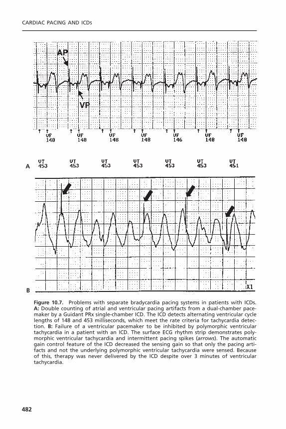
CARDIAC PACING AND ICDS
482
Figure 10.7. Problems with separate bradycardia pacing systems in patients with ICDs.A: Double counting of atrial and ventricular pacing artifacts from a dual-chamber pace-maker by a Guidant PRx single-chamber ICD. The ICD detects alternating ventricular cyclelengths of 148 and 453 milliseconds, which meet the rate criteria for tachycardia detec-tion. B: Failure of a ventricular pacemaker to be inhibited by polymorphic ventriculartachycardia in a patient with an ICD. The surface ECG rhythm strip demonstrates poly-morphic ventricular tachycardia and intermittent pacing spikes (arrows). The automaticgain control feature of the ICD decreased the sensing gain so that only the pacing arti-facts and not the underlying polymorphic ventricular tachycardia were sensed. Becauseof this, therapy was never delivered by the ICD despite over 3 minutes of ventriculartachycardia.
B
A

underdetection of the ventricular arrhythmia and failure to deliver therapy, asshown in Figure 10.7B.
The procedure for elective cardioversion and external defibrillation in the ICD patient is similar to that for pacemaker patients described elsewhere in this text. Most ICDs are implanted in the left pectoral region, but older ICDsystems may have been implanted in the left upper abdomen. For the ICDpatient presenting with cardiac arrest, standard advanced cardiac lifesaving pro-tocols for cardiopulmonary resuscitation (CPR) and external defibrillationshould be followed as for any other patient. One should not wait for the ICDto deliver therapy, as malfunctions or ineffective therapies may have alreadyoccurred.
TROUBLESHOOTING IMPLANTABLE CARDIOVERTER-DEFIBRILLATORSTroubleshooting ICD problems encompasses all aspects of bradycardia pace-maker malfunctions as well as evaluation of the appropriateness of therapies for ventricular tachycardia. Several scenarios with ICD patients demand sleuthwork on the part of the follow-up physician. These scenarios include patientspresenting with (1) bradycardia pacing malfunction, (2) single ICD discharge,(3) multiple ICD discharges, (4) syncope with no perceived ICD therapy,and (5) documented sustained ventricular tachycardia without ICD therapy.A careful history and physical examination, and inspection of the com-prehensive data logs and stored electrograms often will provide answers to all ofthese scenarios. Further information can be obtained from the programmeddevice parameters, the device battery and capacitor status, and the lead performance.
Bradycardia Pacing by the Implantable Cardioverter-DefibrillatorAlthough most of the bradycardia pacing functions of the ICD are identical toa simple pacemaker, some features are necessarily different. Because of the highventricular sensitivity and limited blanking periods needed to detect ventricu-lar fibrillation, oversensing by the ICD may be more difficult to avoid or correct.Different parameters may be programmed for post-shock pacing and standardbradycardia pacing; unipolar pacing modes are not available in the ICD. Asdescribed previously, application of a magnet to an ICD inhibits tachycardiatherapies but does not trigger the asynchronous bradycardia pacing mode. Insome ICDs, prolonged magnet application will turn off tachycardia therapies(but bradycardia therapies are unaffected) until another magnet exposure occursor the device is reactivated with the programmer.
Biventricular ICDs incorporate simultaneous left and right ventricularpacing for treatment of congestive heart failure caused by left ventricular dys-synchrony. Failure of either right or left ventricular pacing because of elevatedpacing thresholds or lead dislodgment may change QRS morphology on the electrocardiogram. Double counting of conducted ventricular events couldinhibit pacing.
ICD FOLLOW-UP AND TROUBLESHOOTING
483

Isolated Implantable Cardioverter-Defibrillator Discharge
Approximately 60% to 80% of ICD patients will receive a shock therapy within5 years of implant.20,21 Although ICD shocks are an expected occurrence, eachevent may frighten the patient, and these warrant careful evaluation by the physi-cian. A flow diagram for the evaluation of ICD shocks is shown in Figure 10.8.Before they are discharged from the hospital after ICD implantation, patientsshould be educated about the procedures to follow after an ICD shock. Ourpractice is to have the patient call the office after the first shock is perceived.This allows us to assess the patient’s level of anxiety, partially assess the appro-priateness of the therapy, and provide reassurance.We interrogate the device elec-tively within 1 to 2 days to ensure that the ICD is functioning appropriately.Thereafter, the patient may contact us for the infrequent shocks, depending onhis or her level of comfort. We advise patients to call immediately when morethan two shocks within 24 hours are experienced, as this may indicate faileddevice therapy or inappropriate shocks.
The goal of the physician presented with the patient who has had an ICDshock is to establish whether the therapy was appropriate. A full account of theevents leading up to the shock should be elicited, including activities, medicalcompliance, use of new medications, syncope, palpitations, exposure to EMI,angina, and heart failure. Shocks preceded by syncope or presyncope are almostalways appropriate. Shocks associated with heavy exertion, motion of the armipsilateral to the ICD, or exposure to electromagnetic current sources shouldraise suspicions of sinus tachycardia, lead noise, or EMI interference, respectively.Because approximately 40% of the shocks for ventricular tachycardia are asymp-tomatic, the absence of symptoms before the shock does not indicate a nonar-rhythmic etiology.22 Interrogation of the device therapy log is most useful indetermining the cause of the shock. For ventricular tachycardia episodes, thestored electrograms will usually confirm the diagnosis by demonstrating AV dis-sociation or a change in the morphology compared to sinus rhythm. Otherwise,any noise, supraventricular tachyarrhythmia, or sinus tachycardia will be evident.
Regardless of the cause of the shock, hospitalization for an isolated ICDdischarge is rarely warranted unless changes in the antiarrhythmic drug therapyare needed. Reassuring the patient that the device has functioned properly isalways indicated. If the patient is particularly troubled by the shock, activatingATP therapy or initiating antiarrhythmic drug therapy may minimize recur-rences. For an inappropriate shock, corrective measures must be taken.To avoidsupraventricular tachyarrhythmias triggering inappropriate ICD therapy, activa-tion of SVT discrimination algorithms, or antiarrhythmic or AV nodal block-ing agents may be useful. Myopotential sensing may require reprogramming thedevice’s sensitivity and performing follow-up testing for appropriate ventricularfibrillation detection. Noise should prompt a thorough search for a lead mal-function or any exposure to EMI.
Finally, some patients report ICD discharges when the ICD counters showno therapy being delivered. This phenomenon, called “phantom shocks,” often
CARDIAC PACING AND ICDS
484

485
Figure 10.8. Flow diagram for evaluating ICD shocks. ATP = antitachycardia pacing; EGM= electrocardiograms; EMI = electromagnetic interference; SVT = supraventricular tachy-cardia. *See Box 10.1; **class III drugs include sotalol and dofetilide; not programmablein all devices.
occurs at night and may be due to anxiety, dream states, or hypnagogic con-tractures. Usually, reassurance is all that is needed but psychologic counseling isoccasionally required.
Multiple DischargesMultiple ICD discharges can be either appropriate or inappropriate. A differen-tial diagnosis for multiple ICD discharges is included in Box 10.2. Because mul-tiple ICD discharges often cause significant psychological stress to the patient,they should be considered a medical emergency.
Multiple Appropriate Discharges: Multiple appropriate discharges over minutesto days may result from incessant ventricular tachycardia, related to acuteischemia or infarction, electrolyte abnormalities, drug proarrhythmia, medicalnoncompliance, use of inotropic or pressor agents, or a spontaneous ventriculartachycardia “storm.”23,24 Examination of stored intracardiac electrograms willusually determine whether the shocks are appropriate.
Acute treatment of the patient with multiple appropriate ICD dischargesshould first focus on treating any underlying causes and/or initiating intravenousantiarrhythmic or beta blockade therapy.23 If the patient is receiving multipleappropriate shocks for ventricular tachycardia, reprogramming to include ATPfor ventricular tachycardia may diminish the number of shocks. Sometimes, thepatient may benefit from a longer detection and confirmation time in the VTzone if most of the episodes of ventricular tachycardia are self-terminating. Ifmultiple shocks result from ineffective therapies (i.e., ATP or a low-energy shock failing to convert the ventricular tachycardia), more aggressive initialtherapy may diminish the total number of discharges the patient receives.
If initial therapies fail to terminate ventricular fibrillation, the DFT shouldbe reevaluated, because it may rise over time. An important cause of increasedDFT is drugs, as outlined in Box 9.1. DFT may also change after myocardialinfarction, cardiac surgery, or lead/device movement. Occasionally, ICD systemrevision to change the current path, revise a lead, or install a high-output gen-erator may be needed. Finally, catheter ablation of ventricular tachycardia focimay decrease the number of ventricular tachycardia episodes in drug refractorycases.25
Although this is rarely used today, some ICDs may still be programmed to“committed” mode in which therapy will be delivered after initial tachycardiadetection criteria are met even if the arrhythmia spontaneously terminates.Thismode of operation may result in frequent or multiple shocks for nonsustainedventricular arrhythmias. Some devices are capable of defibrillation therapy foratrial tachyarrhythmias. Multiple low-energy shocks are one strategy to termi-nate atrial fibrillation with these devices as an alternative or prelude to highenergy therapy.
Multiple Inappropriate Discharges: In the case of repeated inappropriate dis-charges, the ICD should be promptly inactivated and the patient placed on
CARDIAC PACING AND ICDS
486

telemetry with external defibrillation capabilities readily available. Most deviceswill have therapies inhibited as long as a magnet is in place over the generator.In some devices, prolonged magnet application will inactivate the device untilthe ICD is reactivated by the programmer or the magnet is applied again. Inap-propriate ICD therapies may have many causes, but the most common cause isatrial fibrillation, as shown in Figure 10.9. Other atrial tachyarrhythmias includ-ing atrial flutter and sinus tachycardia may also trigger inappropriate ICDtherapy. Once the device is inactivated, the atrial arrhythmia can be managedin a conventional manner. If the device cannot be immediately reprogrammed,chemical or electrical conversion of the atrial arrhythmia may be needed if ven-tricular rate control cannot be achieved. After initial control of the supraven-tricular tachyarrhythmia has been achieved, ICD tachyarrhythmia detectionfeatures for discrimination of supraventricular tachyarrhythmia from ventriculartachycardia may be useful in preventing further inappropriate therapies.Presently, it is unclear whether dual-chamber ICDs will decrease the number ofinappropriate ICD therapies for supraventricular tachycardias (Fig. 10.10).Additionally, it is unclear whether the use of ventricular electrogram morphol-ogy algorithms will decrease inappropriate ICD therapies due to SVTs (see Fig.10.10C).Ventricular electrogram morphology discrimination when used in con-junction with other SVT discriminators has a suboptimal sensitivity for atrialtachycardia.26 SVTs with subtle rate-related changes in the QRS complex canalso trigger inappropriate detection of ventricular tachyarrhythmias. Repro-gramming of the percent template match to less rigorous criteria may improve
ICD FOLLOW-UP AND TROUBLESHOOTING
487
Figure 10.9. Atrial fibrillation and inappropriate therapy, as recorded by a GuidantVentak Mini single-chamber ICD. Note the marked irregularity of the intracardiac ven-tricular electrogram (top tracing) and the ventricular cycle length, which varies between290 and 500 milliseconds (bottom tracing, marker channel). The ventricular rate eventu-ally falls into the VT zone (denoted by “TS” marker channel), and then ATP therapy isdelivered (denoted by “TP” marker channel).

CARDIAC PACING AND ICDS
488
Figure 10.10. A: Atrial fibrillation with a rapid ventricular response leading to inappro-priate therapy, as recorded by a Medtronic Gem DR dual-chamber ICD. Atrial electrogram(AEGM), ventricular electrogram (VEGM) and marker channel (MARKER) are shown. Thepatient is in atrial fibrillation with ventricular response from 370 to 500 milliseconds. Theoccasional long cycle lengths and irregularity prevent ventricular tachycardia detection.Panel B: With faster ventricular rate, the rhythm regularizes and no longer meets “unsta-ble” rate criteria for diagnosis of atrial fibrillation in the VT zone. Antitachycardia pacingtherapy is given as a result (arrow). Panel C: Failure of ventricular electrogram morphol-ogy discrimination in a St. Jude Photon dual-chamber ICD. The atrial and right ventricular(RV) channels show 1:1 conduction indicative of sinus tachycardia. Checks alternating with“X”s in the markers channel demonstrate an alternating match and mismatch with thestored ventricular electrogram template recorded in sinus rhythm. The poor match withthe stored template probably results from misalignment of the electrogram with the tem-plate. The patient experienced inappropriate VT detection and ATP therapy.
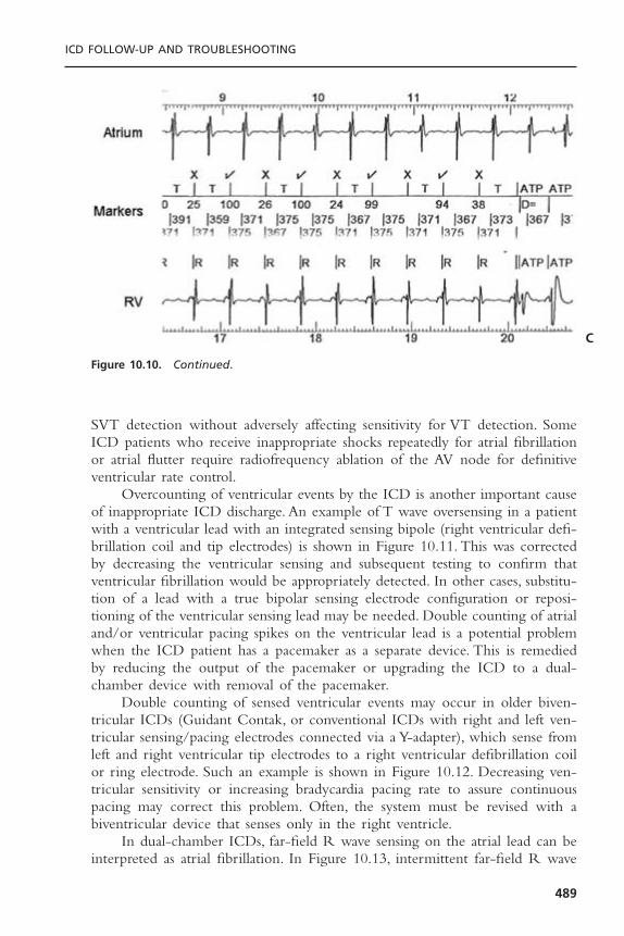
SVT detection without adversely affecting sensitivity for VT detection. SomeICD patients who receive inappropriate shocks repeatedly for atrial fibrillationor atrial flutter require radiofrequency ablation of the AV node for definitiveventricular rate control.
Overcounting of ventricular events by the ICD is another important causeof inappropriate ICD discharge. An example of T wave oversensing in a patientwith a ventricular lead with an integrated sensing bipole (right ventricular defi-brillation coil and tip electrodes) is shown in Figure 10.11. This was correctedby decreasing the ventricular sensing and subsequent testing to confirm thatventricular fibrillation would be appropriately detected. In other cases, substitu-tion of a lead with a true bipolar sensing electrode configuration or reposi-tioning of the ventricular sensing lead may be needed. Double counting of atrialand/or ventricular pacing spikes on the ventricular lead is a potential problemwhen the ICD patient has a pacemaker as a separate device. This is remediedby reducing the output of the pacemaker or upgrading the ICD to a dual-chamber device with removal of the pacemaker.
Double counting of sensed ventricular events may occur in older biven-tricular ICDs (Guidant Contak, or conventional ICDs with right and left ven-tricular sensing/pacing electrodes connected via a Y-adapter), which sense fromleft and right ventricular tip electrodes to a right ventricular defibrillation coilor ring electrode. Such an example is shown in Figure 10.12. Decreasing ven-tricular sensitivity or increasing bradycardia pacing rate to assure continuouspacing may correct this problem. Often, the system must be revised with abiventricular device that senses only in the right ventricle.
In dual-chamber ICDs, far-field R wave sensing on the atrial lead can beinterpreted as atrial fibrillation. In Figure 10.13, intermittent far-field R wave
ICD FOLLOW-UP AND TROUBLESHOOTING
489
Figure 10.10. Continued.
C

CARDIAC PACING AND ICDS
490
Figure 10.11. T wave oversensing causing double counting and inappropriate therapyfor ventricular fibrillation in a Medtronic Gem DR dual-chamber ICD. The atrial channel(top tracing) shows a sinus tachycardia; the ventricular channel (middle tracing) showslarge biphasic repolarization artifacts corresponding to the T wave after each high fre-quency ventricular electrogram. The T wave artifacts are detected as demonstrated bythe marker channel (“FS,” bottom tracing), leading to inappropriate detection of ven-tricular fibrillation.
Figure 10.12. Double counting of intrinsic ventricular rhythm in a Medtronic biven-tricular device. A unipolar lead placed transvenously via the coronary sinus to a lateralcardiac vein was connected to the IS-1 connector of a right ventricular dedicated bipolardefibrillation lead using a Y adapter. The Y adapter was inserted in the IS-1 ventricularport of a conventional Medtronic dual chamber defibrillator. Both tip electrodes of theright and left ventricular leads served as the cathode and the proximal electrode of theright ventricular lead served as the anode, thus creating a large sensing dipole with resul-tant counting of both the right and left ventricular electrograms separately as shown onthe marker channel (QRS complexes with double counting are noted by *). Such doublecounting in the setting of sinus tachycardia can trigger inappropriate therapy.
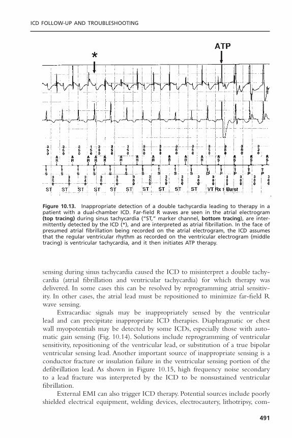
sensing during sinus tachycardia caused the ICD to misinterpret a double tachy-cardia (atrial fibrillation and ventricular tachycardia) for which therapy wasdelivered. In some cases this can be resolved by reprogramming atrial sensitiv-ity. In other cases, the atrial lead must be repositioned to minimize far-field Rwave sensing.
Extracardiac signals may be inappropriately sensed by the ventricular lead and can precipitate inappropriate ICD therapies. Diaphragmatic or chestwall myopotentials may be detected by some ICDs, especially those with auto-matic gain sensing (Fig. 10.14). Solutions include reprogramming of ventricularsensitivity, repositioning of the ventricular lead, or substitution of a true bipolarventricular sensing lead. Another important source of inappropriate sensing is aconductor fracture or insulation failure in the ventricular sensing portion of thedefibrillation lead. As shown in Figure 10.15, high frequency noise secondaryto a lead fracture was interpreted by the ICD to be nonsustained ventricularfibrillation.
External EMI can also trigger ICD therapy. Potential sources include poorlyshielded electrical equipment, welding devices, electrocautery, lithotripsy, com-
ICD FOLLOW-UP AND TROUBLESHOOTING
491
Figure 10.13. Inappropriate detection of a double tachycardia leading to therapy in apatient with a dual-chamber ICD. Far-field R waves are seen in the atrial electrogram(top tracing) during sinus tachycardia (“ST,” marker channel, bottom tracing), are inter-mittently detected by the ICD (*), and are interpreted as atrial fibrillation. In the face ofpresumed atrial fibrillation being recorded on the atrial electrogram, the ICD assumesthat the regular ventricular rhythm as recorded on the ventricular electrogram (middletracing) is ventricular tachycardia, and it then initiates ATP therapy.
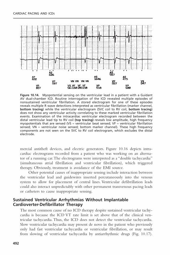
mercial antitheft devices, and electric generators. Figure 10.16 depicts intra-cardiac electrograms recorded from a patient who was working on an alterna-tor of a running car.The electrograms were interpreted as a “double tachycardia”(simultaneous atrial fibrillation and ventricular fibrillation), which triggeredtherapy. Obviously, treatment is avoidance of the EMI source.
Other potential causes of inappropriate sensing include interaction betweenthe ventricular lead and guidewires inserted percutaneously into the venoussystem to allow for placement of central lines. Ventricular defibrillation leadscould also interact unpredictably with other permanent transvenous pacing leadsor catheters to cause inappropriate sensing.
Sustained Ventricular Arrhythmias Without ImplantableCardioverter-Defibrillator Therapy
The most common cause of no ICD therapy despite sustained ventricular tachy-cardia is because the ICD VT rate limit is set above that of the clinical ven-tricular tachycardia. Thus, the ICD does not detect the ventricular tachycardia.Slow ventricular tachycardia may present de novo in the patient who previouslyonly had fast ventricular tachycardia or ventricular fibrillation, or may resultfrom slowing of ventricular tachycardia by antiarrhythmic drugs (Fig. 10.17).
CARDIAC PACING AND ICDS
492
Figure 10.14. Myopotential sensing on the ventricular lead in a patient with a GuidantAV dual-chamber ICD. Routine interrogation of the ICD revealed multiple episodes ofnonsustained ventricular fibrillation. A stored electrogram for one of these episodesreveals multiple R wave detections interpreted as ventricular fibrillation (marker channel,bottom tracing) while the ventricular electrogram (SVC coil to RV coil, bottom tracing)does not show any ventricular activity correlating to these marked ventricular fibrillationevents. Examination of the intracardiac ventricular electrogram recorded between thedistal ventricular lead tip to RV coil (top tracing) reveals low amplitude, high frequencymyopotentials that are sensed (VS = ventricular beat sensed; VF = ventricular fibrillationsensed; VN = ventricular noise sensed; bottom marker channel). These high frequencycomponents are not seen on the SVC to RV coil electrogram, which excludes the distalelectrode.
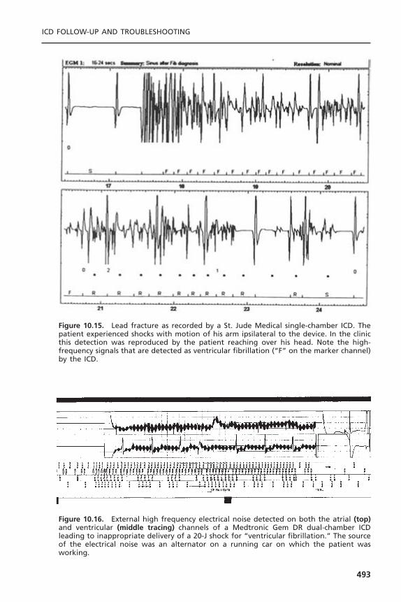
ICD FOLLOW-UP AND TROUBLESHOOTING
493
Figure 10.15. Lead fracture as recorded by a St. Jude Medical single-chamber ICD. Thepatient experienced shocks with motion of his arm ipsilateral to the device. In the clinicthis detection was reproduced by the patient reaching over his head. Note the high-frequency signals that are detected as ventricular fibrillation (“F” on the marker channel)by the ICD.
Figure 10.16. External high frequency electrical noise detected on both the atrial (top)and ventricular (middle tracing) channels of a Medtronic Gem DR dual-chamber ICDleading to inappropriate delivery of a 20-J shock for “ventricular fibrillation.” The sourceof the electrical noise was an alternator on a running car on which the patient wasworking.

Programming errors that may prevent therapy being delivered for ventriculartachyarrhythmias include:
1. Failure to reprogram tachyarrhythmia detections/therapies that have beentemporarily suspended in patients undergoing surgery.
2. Only ventricular fibrillation therapies being programmed in the patient whopreviously has only had ventricular fibrillation but subsequently develops aslower ventricular tachycardia.
3. Overly aggressive supraventricular tachyarrhythmia discrimination schemescausing underdetection of ventricular tachycardia.
4. Intentionally very long initial detection algorithms for hemodynamicallystable ventricular tachycardia.
5. Inadvertent device inactivation due to magnet exposure.6. Low programmed ventricular sensitivity with failure to detect ventricular
tachycardia/ventricular fibrillation.
System component failure is another important cause of delay or failure indelivery of effective therapy.This may include battery or capacitor failure causingprolonged charge times (Fig. 10.18). Lead problems contributing to failure todetect ventricular tachyarrhythmias or to deliver effective therapy include con-ductor fracture or insulation failure in either the ventricular rate sensing or highvoltage circuits. Deterioration of the sensing characteristics of the ventricularlead over time can also result in failure to detect low amplitude electrogramsduring ventricular tachycardia or ventricular fibrillation.
CARDIAC PACING AND ICDS
494
Figure 10.17. A: Failure to detect sustained ventricular tachycardia by an ICD due to atachycardia rate slower than the programmed rate limit. The patient had received amio-darone therapy for 3 years before presenting with sustained ventricular tachycardia at145bpm. Because the VT detection rate limit was set at 160bpm, the ICD did not iden-tify ventricular tachycardia as being present. B: By reducing the rate limit to 130bpm,the ventricular tachycardia was readily detected and terminated with a single burst ofATP.
A
B

The ICD patient who presents with a sustained ventricular tachyarrhyth-mia should be promptly treated using accepted advanced cardiac life supportprotocols. The ICD should be inactivated until possible causes of malfunctionhave been explored (see Box 10.2).
Syncope with No Apparent Implantable Cardioverter-Defibrillator Discharge
Patients may present with a syncopal episode but no perceived ICD therapy.The patient workup should focus on whether the likely cause of syncope is dueto a ventricular tachyarrhythmia. Box 10.3 lists a differential diagnosis for thisscenario. If a ventricular tachyarrhythmia is the presumed cause of the syncope,a full device interrogation and lead testing will provide valuable clues as towhether system failure may have occurred. Often, a system failure has notoccurred; rather, the patient has lost consciousness prior to ICD therapy. Thismay occur because of inappropriately long detection and redetection intervalsor very complex tiered therapy schemes for ventricular tachycardia that mayunnecessarily delay effective treatment. An example of a complex ventriculartachycardia therapy scheme that delayed definitive therapy for over 60 secondsis shown in Figure 10.19.
The patient may have symptomatic ventricular tachyarrhythmia episodesthat are not registered by the ICD. Reasons for this include ventricular tachy-cardia slower than the programmed rate limits, supraventricular tachyarrhythmiadiscrimination algorithms preventing detection of ventricular tachycardia, andventricular undersensing. If this situation is suspected, liberalization of detectioncriteria or activation of a slow VT zone may help to protect the patient untila definitive diagnosis can be made.
It should be remembered that not all syncope in the ICD patient is dueto a ventricular arrhythmia. Bradyarrhythmias are also an important cause. Syn-cope may result from failure of bradycardia pacing in the pacemaker-dependent
ICD FOLLOW-UP AND TROUBLESHOOTING
495
Figure 10.18. Prolonged charge time causing a delay in therapy and syncope in a patientwith a Medtronic 7221 ICD. Examination of the therapy sequence report from this patientreveals a charge time of 20.6 seconds to deliver a 20-J shock for ventricular fibrillation.This could result from capacitor or component failure, or from battery voltage near theend of the battery’s life.
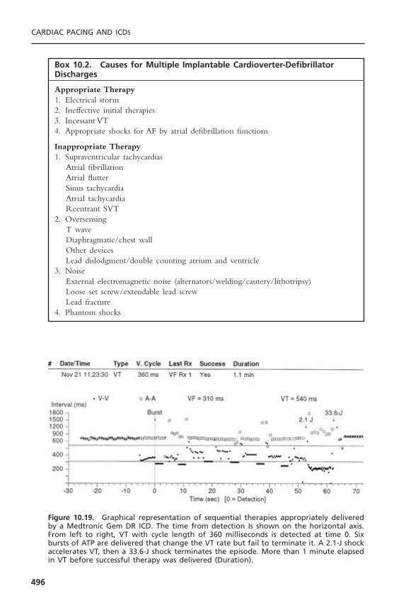
CARDIAC PACING AND ICDS
496
Box 10.2. Causes for Multiple Implantable Cardioverter-DefibrillatorDischarges
Appropriate Therapy1. Electrical storm2. Ineffective initial therapies3. Incessant VT4. Appropriate shocks for AF by atrial defibrillation functions
Inappropriate Therapy1. Supraventricular tachycardias
Atrial fibrillationAtrial flutterSinus tachycardiaAtrial tachycardiaReentrant SVT
2. OversensingT waveDiaphragmatic/chest wallOther devicesLead dislodgment/double counting atrium and ventricle
3. NoiseExternal electromagnetic noise (alternators/welding/cautery/lithotripsy)Loose set screw/extendable lead screwLead fracture
4. Phantom shocks
Figure 10.19. Graphical representation of sequential therapies appropriately deliveredby a Medtronic Gem DR ICD. The time from detection Is shown on the horizontal axis.From left to right, VT with cycle length of 360 milliseconds is detected at time 0. Sixbursts of ATP are delivered that change the VT rate but fail to terminate it. A 2.1-J shockaccelerates VT, then a 33.6-J shock terminates the episode. More than 1 minute elapsedin VT before successful therapy was delivered (Duration).

ICD patient due to ventricular oversensing, loss of capture, lead malfunction,or ICD battery depletion. Other causes of syncope in the ICD patient includeneurocardiogenic syncope, orthostatic hypotension, seizure, hypoglycemia, andpsychogenic causes.
CONCLUSIONPatients who have ICDs need regular follow-up assessments to ascertain whetherthe ICD is functioning correctly. Follow-up assessments of the ICD encompassall aspects of pacemaker maintenance plus the complexities of automated tachy-arrhythmia detection and treatment. In the case of suspected ICD malfunction,stored electrograms and noninvasive testing capabilities have simplified trouble-
ICD FOLLOW-UP AND TROUBLESHOOTING
497
Box 10.3. Syncope with Delayed or AbsentImplantable Cardioverter-Defibrillator Therapy
1. Ventricular tachyarrhythmias• Device
Battery depletionCapacitor failureOther electronic failure
• Lead relatedFracture of defibrillation circuitFracture of rate-sensing circuitLead dislodgment
• ProgrammingDevice inactivatedDetect and redetect intervals too longSVT discrimination inhibits therapyVT rate under rate limitInitial therapies accelerate VTIneffective initial therapiesUndercounting due to signal size
• Underlying substrateIncreased defibrillation threshold
DrugsCongestive heart failureIschemiaElectrolyte abnormalities
2. Non-arrhythmic causes of syncope• Bradyarrhythmia and intolerance of ventricular pacing• Failure of bradycardia pacing• Seizure• Neurocardiogenic syncope• Orthostasis
shooting and help to determine the possible causes of malfunctions. Never-theless, vigilance and a thorough understanding of ICD function remain essen-tial to ICD follow-up assessments.
REFERENCES1. Zucker MJ, Bloch GJ. Syncope and the law. In: Grubbs BP, Olshansky B, eds.
Syncope: Mechanisms and Management. Armonk, NY: Futura, 1998:387–401.2. Carnes CA, Mehdirad AA, Nelson SD. Drug and defibrillator interactions. Pharma-
cotherapy 1998;18:516–525.3. Fletcher RD, Cintron GB, Johnson G, et al. Enalapril decreases prevalence of ven-
tricular tachycardia in patients with chronic congestive heart failure: the V-HeFT IIVA cooperative studies group. Circulation 1993;87(suppl 6):49–55.
4. Hjalmarson A. Prevention of sudden cardiac death with beta blockers. Clin Cardiol1999;22(suppl 8):11–15.
5. De Sutter J,Tavernier R, De Buyzere M, et al. Lipid lowering drugs and recurrencesof life-threatening ventricular arrhythmias in high-risk patients. J Am Coll Cardiol2000;36:766–772.
6. Brodksy CM, Chang F, Vlay SC. Multicenter evaluation of implantable cardioverterdefibrillator testing after implant: the Post Implant Testing Study (PITS). Pacing ClinElectrophysiol 1999;22:1769–1776.
7. Glikson M, Luria D, Friedman PA, et al. Are routine arrhythmia inductions neces-sary in patients with pectoral implantable cardioverter defibrillators? J CardiovascElectrophysiol 2000;11:127–135.
8. Kohlkamp K, Dornberger V, Mewis C, et al. Clinical experience with the new detec-tion algorithms for atrial fibrillation of a defibrillator with dual chamber sensingand pacing. J Cardiovasc Electrophysiol 1999;10:905–915.
9. Nanthakumar K, Dorian P, Paquette M, et al. Is inappropriate implantable defibril-lator shock therapy predictable? J Intervent Card Electrophysiol 2003;8:215–220.
10. Leitch JW, Gillis AM, Wyse DG, et al. Reduction in defibrillator shocks with animplantable device combining antitachycardia pacing and shock therapy. J Am CollCardiol 1991;18:145–151.
11. Naisir N, Pacifico A, Doyle TK, et al. Cadence Investigators. Spontaneous ventric-ular tachycardia treated by antitachycardia pacing. Am J Cardiol 1997;79:820–822.
12. Wood MA, Stambler BS, Damiano RJ, et al. Lessons learned from data logging in a multicenter clinical trial using a late-generation implantable cardioverter-defibrillator. J Am Coll Cardiol 1994;24:1692–1699.
13. Exner DV, Gillis AM, Sheldon RS, et al. Telemetry-documented, paceterminable ventricular tachycardia in patients with ventricular fibrillation. Am J Cardiol1998;81:235–238.
14. Schaumann A, von zur Muhlen F, Herse B, et al. Empirical versus tested antitachy-cardia pacing in implantable cardioverter-defibrillators. Circulation 1998;97:66–74.
15. Gillis AM, Leitch JW, Sheldon RS, et al. A prospective randomized comparison ofautodecremental pacing to burst pacing in device therapy for chronic ventriculartachycardia secondary to coronary artery disease. Am J Cardiol 1993;72:1146–1151.
16. Wathen MS, Sweeney MO, DeGroot PJ, et al. Shock reduction using antitachycar-dia pacing for spontaneous rapid ventricular tachycardia in patients with coronaryartery disease. Circulation 2001;104:796–801.
CARDIAC PACING AND ICDS
498

17. Florin TJ,Weiss DN, Peters RW, et al. Induction of atrial fibrillation with low-energydefibrillator shocks in patients with implantable cardioverter defibrillators. Am JCardiol 1997;80:960–962.
18. Kroll MW, Tchou PJ. Testing of implantable defibrillator functions at implantation.In: Ellenbogen KA, Kay GN, Wilkoff BL, eds. Clinical cardiac pacing and defibril-lation. 2nd ed. Philadelphia: WB Saunders, 2000:540–561.
19. Gold MR, Higgins S, Klein R, et al. Efficacy and temporal stability of reduced safetymargins for ventricular defibrillation. Circulation 2002;105:2043–2048.
20. Fogoros RN, Elson JJ, Bonnet CA. Actuarial incidence and pattern of occurrenceof shocks following implantation of the automatic implantable cardioverter defi-brillator. Pacing Clin Electrophysiol 1989;12:1465–1473.
21. Grimm W, Flores BT, Marchlinski FE. Shock occurrence and survival in 241 patientswith implantable cardioverter-defibrillator therapy. Circulation 1993;87:1880–1887.
22. Hook BG, Callans DJ, Kleiman RB, et al. Implantable cardioverter-defibrillatortherapy in the absence of significant symptoms. Rhythm diagnosis and managementaided by stored electrogram analysis. Circulation 1993;87:1897–1906.
23. Nademanee K, Taylor R, Bailey WE, et al. Treating electrical storm: sympatheticblockade versus advanced cardiac life support-guided therapy. Circulation 2000;102:742–747.
24. Wood MA, Simpson PM, Stambler BS, et al. Long-term temporal patterns of ven-tricular tachyarrhythmias. Circulation 1995;91:2371–2377.
25. Lauribe P, Shah D, Jais P, et al. Radiofrequency catheter ablation of drug refractorysymptomatic ventricular ectopy: short- and long-term results. Pacing Clin Electro-physiol 1999;22:783–789.
26. Boriani G, Biffi M, Dall’Acqua A, et al. Rhythm discrimination by rate branch andQRS morphology in dual chamber implantable cardioverter defibrillators. PacingClin Electrophysiol 2003;26:466–470.
ICD FOLLOW-UP AND TROUBLESHOOTING
499
500
THE GOALS OF PACEMAKER FOLLOW-UP ASSESSMENTPacemaker follow-up evaluations entail the repeated assessment of the pacingsystem and the patient to ensure appropriate and optimal pacer function and todetect and prevent pacemaker-related problems. The follow-up evaluation of apacemaker patient begins in the immediate postimplantation period and extendsthroughout the patient’s life, rather than throughout the life of the pacemakersystem per se.The original indications for pacemaker insertion require periodicreview, and new indications for modifications of the existing system also warrantcontinuing evaluation.The pacemaker physician needs to assess those symptomsnot satisfactorily treated by the pacemaker as well as those symptoms potentiallycaused by the pacemaker. Systematic record-keeping is an important part of thisprocess, particularly in following end-of-life parameters and in tracking patientswhose systems may be subject to product recall or failure.
It remains a challenge to optimize the functioning and longevity of a pace-maker system in the face of constantly changing patient needs, whether thosechanges are in lifestyle, medical circumstances, cardiac function, or electrophys-iologic milieu. The issue of who should perform pacemaker follow-up evalua-tions remains an ongoing debate—what is clear is that the relevant skills mustbe continuously and finely maintained.1,2 This chapter explores these issues andexamines the methodology of the pacemaker follow-up evaluation.3–6
THE IMMEDIATE POSTIMPLANTATION PERIODFollowing the implantation of a new pacemaker system, the patient is generallyobserved on a cardiac monitor for 24 hours to confirm adequate pacemakerfunction. The roles of ambulatory pacemaker implantation and shorter hospitalstays remain controversial. Most patients receive prophylactic antibiotic coveragefor at least 24 hours following pacer insertion.This practice is supported by theresults of a meta-analysis.7 Posteroanterior (PA) and lateral chest radiographs areobtained within 24 hours to confirm satisfactory positioning of the pacer lead(s)
11Follow-up Assessments of the
Pacemaker PatientMark H. Schoenfeld and Mark L. Blitzer

and to serve as a baseline for subsequent comparisons. Twelve-lead electrocar-diograms both with and without pacing are obtained before discharge.
Most essential in the immediate postimplantation period is education ofthe patient. The importance of always carrying a pacemaker identification cardmust be stressed. Medical alert bracelets are often recommended as well. Thepatient is asked to refrain from vigorous activity involving the ipsilateral arm fora period of approximately 4 weeks to minimize the possibility of lead dislodg-ment. Also the patient should keep the incision completely dry for 5 to 7 daysto minimize the chance of infection. One of the questions most commonlyasked by patients prior to discharge is whether microwave ovens need to beavoided; with modern-day generators the answer is “no.” Temporary drivingrestrictions may be appropriate for patients presenting with syncope until thefollow-up assessment confirms that the pacemaker is functioning normally. Plansare then made for outpatient wound evaluation and suture or staple removal ifneeded, generally to occur within 2 to 4 weeks. Patients are asked to be atten-tive to any signs of fever or infection such as pain, redness, swelling, or drainageat the incision site.
THE FOLLOW-UP CLINIC AND RECORD-KEEPINGThe personnel necessary to the pacemaker follow-up assessment includes asupervising physician, a pacemaker nurse or technician, and clerical staff forrecord-keeping and outpatient scheduling. Personnel directly involved in thepacemaker follow-up evaluation must be thoroughly familiar with all aspects ofpacemaker function. The site of the pacemaker follow-up evaluation shouldallow history taking and patient examination and should be fully equipped toallow for analysis of pacemaker function (Box 11.1). This includes capabilitiesfor 12-lead electrocardiography (with and without a magnet), radiography (andfluoroscopy, if possible), transtelephonic and ambulatory electrocardiographicmonitoring, and availability of the programmers and physician’s manual for everymodel of pacemaker encountered.The telephone numbers for technical supportof all pacemaker manufacturers should be available. Depending on the numberof different pacer models employed by the clinic, extensive familiarity with awide variety of programming devices may be necessary because of the lack ofuniversal programming.8 A resuscitation cart, defibrillator, and transcutaneouspacemaker should be immediately available. The clinic staff should be capableof performing advanced life support.
Record-keeping is an indispensable component of a pacemaker clinic. Itspurpose is to accurately record such patient demographics as name and address,to identify specifics of the pacer system used (model and serial numbers, implantvalues), to track patient symptoms and various parameters of pacemaker func-tion (e.g., sensing and pacing thresholds, identified changes in magnet rate), andto update any changes in programmed parameters. Such records may be com-puter stored and allow for the generation of comprehensive updated reports.9
Record-keeping also allows for organization and maintenance of strict sched-
FOLLOW-UP ASSESSMENTS OF THE PACEMAKER PATIENT
501
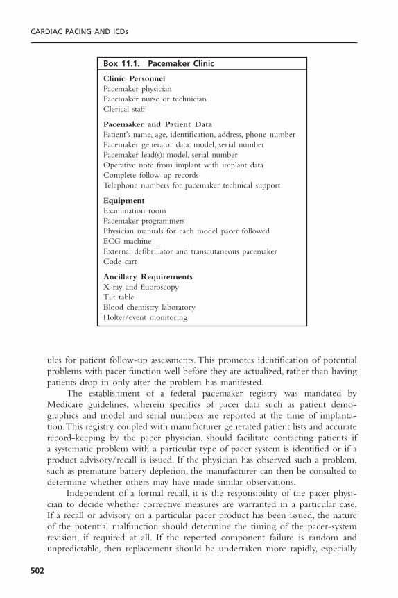
ules for patient follow-up assessments. This promotes identification of potentialproblems with pacer function well before they are actualized, rather than havingpatients drop in only after the problem has manifested.
The establishment of a federal pacemaker registry was mandated byMedicare guidelines, wherein specifics of pacer data such as patient demo-graphics and model and serial numbers are reported at the time of implanta-tion.This registry, coupled with manufacturer generated patient lists and accuraterecord-keeping by the pacer physician, should facilitate contacting patients if a systematic problem with a particular type of pacer system is identified or if aproduct advisory/recall is issued. If the physician has observed such a problem,such as premature battery depletion, the manufacturer can then be consulted todetermine whether others may have made similar observations.
Independent of a formal recall, it is the responsibility of the pacer physi-cian to decide whether corrective measures are warranted in a particular case.If a recall or advisory on a particular pacer product has been issued, the natureof the potential malfunction should determine the timing of the pacer-systemrevision, if required at all. If the reported component failure is random andunpredictable, then replacement should be undertaken more rapidly, especially
CARDIAC PACING AND ICDS
502
Box 11.1. Pacemaker Clinic
Clinic PersonnelPacemaker physicianPacemaker nurse or technicianClerical staff
Pacemaker and Patient DataPatient’s name, age, identification, address, phone numberPacemaker generator data: model, serial numberPacemaker lead(s): model, serial numberOperative note from implant with implant dataComplete follow-up recordsTelephone numbers for pacemaker technical support
EquipmentExamination roomPacemaker programmersPhysician manuals for each model pacer followedECG machineExternal defibrillator and transcutaneous pacemakerCode cart
Ancillary RequirementsX-ray and fluoroscopyTilt tableBlood chemistry laboratoryHolter/event monitoring
in those patients who are deemed “pacer-dependent.” Unfortunately, as of thiswriting, there is no manufacturer-independent, large-scale national device/leaddatabase that allows physicians and their patients to be notified in a timelyfashion of pacemaker system malfunctions.10 Thus, the pacer physician must beever vigilant as to trends of potential pacer malfunction in his or her practiceas well as to reports from others, whether via other physicians or manufactur-ers’ notifications.
THE OUTPATIENT VISITEven a routine pacemaker follow-up visit is a labor-intensive encounter withmuch to be accomplished in a timely manner including a brief history, exam-ination, pacemaker evaluation, troubleshooting, reprogramming, and record-keeping. By keeping the goals of the visit in focus and maintaining an orderlyapproach to follow-up, the process can be made efficient (Fig. 11.1).
The first visit, approximately 2 to 4 weeks subsequent to implantation, isprimarily directed toward evaluation of the healing wound. This is particularlyimportant in diabetic patients prone to slower healing and patients requiringanticoagulation, in whom pocket hematomas can prove catastrophic.11 Symp-toms are reviewed as with any visit. Chest radiographs (PA and lateral) and elec-trocardiograms with and without pacing can be repeated at this time. Mostproblems arising within 2 weeks of implantation relate to either lead dislodg-ment, exit block, or healing of the incision or pocket. Arrangements fortranstelephonic monitoring according to preset guidelines are made, as well asfor the 3-month checkup. At that point, the inflammation associated with thetissue-electrode interface has generally resolved, allowing for assessment ofchronic pacing and sensing thresholds. After the 3-month checkup, patients aregenerally seen twice yearly, or as otherwise dictated by their clinical needs (Table11.1).
HistorySubsequent visits should focus on device maintenance, optimization of function,and evaluation of patient complaints. The elicitation and evaluation of symp-tomatology requires careful sleuthing on the part of the pacemaker physician.Perceptions of pain, well being, or vigor may vary widely from patient to patient,depending on an individual’s “threshold” for discomfort or malaise. These mayalso be a function of a patient’s fears and expectations. If the patient does notfeel “100% better” after pacer insertion, does this reflect malfunction, or werethe patient’s original symptoms multifactorial in etiology and not preventableby pacing alone? As such, it is sometimes difficult to distinguish symptoms thatwarrant only reassurance from those that may be subtle clues to underlyingpacemaker malfunction, malprogramming, or “patient–pacer mismatch.”
In pacer–patient mismatch, the pacer system may be functioning perfectlyappropriately but fails to result in optimal patient functioning and indeed mayeven produce symptoms. For example, a previously vigorous patient who
FOLLOW-UP ASSESSMENTS OF THE PACEMAKER PATIENT
503

CARDIAC PACING AND ICDS
504
Figure 11.1. Flow chart for efficient pacemaker follow-up visit. Sx = symptoms; ERI =elective replacement indicators; CXR = chest radiograph.

FOLLO
W-U
P ASSESSM
ENTS O
F THE PA
CEM
AK
ER PA
TIENT
505
Table 11.1. Schedules for Pacemaker Follow-up
Outpatient Office Visit Transtelephonic Monitoring
General Guidelines Medicare Guidelines Medicare Guideline I Medicare Guideline II
Appropriate All patients All patients Pacemakers with proven 5-yr Pacemakers with inability to patients longevity >90% and nonabrupt demonstrate 5-yr longevity
decline in output over ≥3mo. >90% and nonabrupt decline in output over ≥3mo (applies to most pacemakers).
Schedule • 2–4wk after implant • Twice in first 6mo. Single chamber Single chamber• 3mo after implant, then after implant, then • First month: Every 2wk. • First month: Every 2 wk.• Every 6mo thereafter until Single chamber • 2nd to 36th mo: Every 8wk. • 2nd to 48th mo: Every 12wk.
approaching elective • Once every 12mo. • Thereafter: Every 4wk. • 49th to 72nd mo: Every 8wk.replacement indicators. Dual chamber Dual chamber Dual chamber
• Once every 6mo. • First month: Every 2wk. • First month: Every 2wk.• 2nd to 6th mo: Every 4wk. • 2nd to 30th mo: Every 12wk.• 7th to 36th mo: Every 8wk. • 31st to 48th mo: Every 8 wk.• Thereafter: Every 4 wk. • Thereafter: Every 4 wk.

receives a dual-chamber system for complete heart block may be exertionallylimited with an upper tracking rate of only 120 beats per minute (bpm), espe-cially if electrical Wenckebach or 2 :1 heart block develops at the pacemaker’supper rate limit (Fig. 11.2). Treadmill testing may, on occasion, be useful inassessing exercise tolerance, chronotropic competence, and maximal heart ratesachievable, either independent of pacing or in the setting of specifically pro-grammed parameters. In rate-adaptive systems it is particularly useful to assessactivity-sensing thresholds as well as the rapidity of pacing rate increases anddecreases with activity. For example, in an older patient who develops angina itmay be important to make the system less sensitive to activity, lower the upperrate limit, and have a relatively quicker decline of pacing rate once activityceases. Upper rate behavior in dual-chamber systems may also be appreciatedwith exercise testing (e.g., Wenckebach versus 2 :1 block); exercise-inducedarrhythmias potentially contributing to pacer-mediated tachycardias may rarelybe observed.
Cardiac symptoms of angina or congestive heart failure may arise unrelatedto the pacer, or to the arrhythmia that had prompted its original implantation.Pacer adjustments may, however, result in alleviation of these symptoms in somecases. The lower rate limit may be increased in patients with so-called “rate-limited cardiac output” to minimize their congestive heart failure. In contrast,patients with angina requiring increased time for diastolic coronary perfusionmay benefit from a reduction in their rate limit or changes to their rate responseparameters as discussed previously.
Symptoms reminiscent of the bradyarrhythmia for which a pacer wasinserted may reappear, either because of pacemaker malfunction or, paradoxi-cally, because of appropriate cardiac pacing that is poorly tolerated by thepatient.12 Reported symptoms may include dizziness, presyncope, or syncope,but may extend to more subtle concerns such as weakness, fatigability, anddyspnea. The appearance of these symptoms in the presence of a well-functioning pacer system may result from “pacemaker syndrome.”13–15 This
CARDIAC PACING AND ICDS
506
Figure 11.2. Holter transmission in a dual-chamber system with ventricular tracking atthe upper rate of 120ppm associated with electrical Wenckebach phenomenon. This vig-orous patient reported exercise limitation and dyspnea in association with this upper ratelimitation.
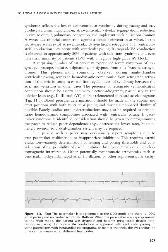
syndrome reflects the loss of atrioventricular synchrony during pacing and mayproduce systemic hypotension, atrioventricular valvular regurgitation, reductionin cardiac output, pulmonary congestion, and unpleasant neck pulsations (cannonA waves due to atrial contraction against a closed atrioventricular valve). In theworst-case scenario of atrioventricular dyssynchrony, retrograde 1:1 ventriculo-atrial conduction may occur with ventricular pacing. Retrograde VA conductionis observed in approximately 80% of patients with sick sinus syndrome and evenin a small minority of patients (15%) with antegrade high-grade AV block.
A surprising number of patients may experience severe symptoms of pre-syncope, syncope, malaise, palpitations, or dyspnea from this “pacemaker syn-drome.” This phenomenon, commonly observed during single-chamberventricular pacing, results in hemodynamic compromise from retrograde activa-tion of the atria in some cases and from cyclic losses of synchrony between theatria and ventricles in other cases. The presence of retrograde ventriculoatrialconduction should be ascertained with electrocardiography, particularly in theinferior leads (e.g., II, III, and aVf ) and/or telemetered intracardiac electrograms(Fig. 11.3). Blood pressure determinations should be made in the supine anderect positions with both ventricular pacing and during a nonpaced rhythm ifpossible. Rarely, cardiac output determinations may also be required to demon-strate hemodynamic compromise associated with ventricular pacing. If pace-maker syndrome is identified, consideration should be given to reprogrammingthe pacer to reduce pacer dependence (e.g., decrease the lower rate), but ulti-mately revision to a dual-chamber system may be required.
The patient with a pacer may occasionally report symptoms due to true pacemaker malfunction or inappropriate inhibition. This requires carefulevaluation—namely, determination of sensing and pacing thresholds and con-sideration of the possibility of pacer inhibition by myopotentials or other elec-tromagnetic interference. Other potentially symptomatic arrhythmias such asventricular tachycardia, rapid atrial fibrillation, or other supraventricular tachy-
FOLLOW-UP ASSESSMENTS OF THE PACEMAKER PATIENT
507
Figure 11.3. Top: The pacemaker is programmed to the DDD mode and there is 100%atrial pacing and no cardiac symptoms. Bottom: When the pacemaker was reprogrammedto the VVIR mode, the patient was dyspneic and became presyncopal despite rate-responsive pacing. Retrograde VA conduction is apparent with ventricular pacing. In some pacemakers with intracardiac electrograms, or marker channels, the VA conductiontime can be measured at different heart rates.
cardias (SVT) need to be investigated as possibilities.Virtually all newer pacingsystems have sophisticated diagnostics, often storing the actual electrogram fromany such tachycardia. This greatly simplifies evaluation. Many pacemakers allowthe clinician to attempt to terminate the SVTs with rapid atrial pacing if the patient were in persistent tachycardia at the time of a follow-up visit.Additionally, certain recent pacemakers even allow for the programming of atrial antitachycardia pacing to be automatically delivered for certain SVT.Pacemaker-mediated tachycardias may also arise and generate symptoms. Re-programming options to “defeat” PMT are addressed later in the chapter. Tilttesting may prove useful in revealing the presence of vasodepressor syncope.Under such circumstances, medical therapy with volume expansion, beta block-ers or vasoconstrictors may prove useful. Pacemaker re-programming may alsobe beneficial. Increasing the lower pacing rate or activating certain specialized“rate-drop” algorithms may provide assistance. There is also early evidence thatcertain rate-adaptive sensors responsive to cardiac contractility may be particu-larly efficacious in minimizing recurrent vasovagal spells.16 The extent that anypacing system can improve on vasovagal syncope, although this remains a sourceof controversy.17
Symptoms that are noncardiac but pacer-related may include myopectoralstimulation (most common in unipolar systems in which the generator caseserves as the anode), concerns related to the pacemaker wound itself (pain, overterosion) or diaphragmatic stimulation (reflecting pacing either through a thinright ventricular wall or via a lead in the vicinity of a phrenic nerve).The latteris clearly increasing in frequency with greater use of biventricular pacing systemswhere the LV lead is often in close apposition to and poorly insulated from theleft phrenic nerve.A summary of commonly reported symptoms and their causesis given in Table 11.2.
Physical ExaminationThe physical examination is a critical aspect of pacemaker follow-up evalua-tions. Most attention will be directed toward the healing incision and pacerpocket, looking for erythema, tenderness, incipient or overt erosion, or pockethematoma. Pocket hematomas occur in approximately 20% of patients whoreceive subcutaneous or intravenous heparin shortly postprocedure.18 While ahematoma does not imply an infection exists, the risk of subsequent infectionis heightened and most would advocate prolonging the period of prophylacticantibiotics until the hematoma has resolved. Conservative management is all thatis usually required with temporary cessation of anticoagulants and more frequentfollow-up to look for signs of pressure necrosis. Premature percutaneous aspira-tion of the pocket may actually be counterproductive diminishing the tam-ponading effect and increasing chances of further bleeding and infection.
Patients may note caudal migration of the generator or superficiality of thepacemaker leads, but these phenomena are infrequent and of concern only rarely.In a healthy pocket, the generator is freely mobile beneath the skin. An immo-bile generator especially when firmly adherent to the overlying skin raises the
CARDIAC PACING AND ICDS
508

possibility of occult infection or pre-erosion. Erosion of a generator or a leadis potentially quite serious and may result in systemic infection (Fig. 11.4). Avariety of approaches to “salvaging” an eroded system have been advocated,although ideally the entire system (including leads) should be explanted andreplaced with a new system after an appropriate period of intravenous antibi-otics. Swelling over the pulse generator may represent hematoma formation,seroma, or pocket infection. A fluctuant pocket should not be aspirated, as thismay introduce infection into a sterile process and will not treat an infection ifpresent. Suspected pocket infections should be surgically opened to confirm thediagnosis and to remove all hardware from an infected pocket. Pacemaker infec-tions are not adequately treated by prolonged courses of antibiotics alone.
Myopectoral stimulation may be appreciated at the pocket site and is almostexclusively seen in unipolar systems. Certain generators are manufactured withone insulated side meant to be placed against the pectoral muscle. Rarely,myopectoral stimulation may be attributed to placement of such a generator canwith the uninsulated side down against the pectoral muscle, leading to anodalstimulation of the underlying muscles; it may thus be corrected by inversion of
FOLLOW-UP ASSESSMENTS OF THE PACEMAKER PATIENT
509
Table 11.2. Common Symptoms in Pacemaker Patients
Symptom Possible Causes
Swelling/pain at pacer site Infection, hematoma, generator migration, Twiddler’ssyndrome, skin erosion, subclavian thrombosis,pectoral stimulation
Exercise intolerance, dyspnea on Pacemaker syndrome, low maximal heart rate settings,exertion inadequate rate response settings, failure to capture,
chronotropic incompetence Dyspnea at rest Pacemaker syndrome, pericardial effusion, failure to
capture, pulmonary emboli from pacer leadsPalpitations Atrial arrhythmias (tracked or conducted), pacemaker-
mediated tachycardia, overly aggressive rate responsesettings, myopotential tracking, sensor-driventachycardias, ventricular arrhythmias, pacemakersyndrome
Skeletal muscle/diaphragmatic Pectoral muscle stimulation (unipolar), insulation stimulation failure, phrenic nerve stimulation, lead perforation,
diaphragm stimulation through ventricleChest pain Pericarditis, lead perforation, angina due to excessive
rate response, pacemaker syndromeSyncope, presyncope Pacemaker syndrome, failure to capture, oversensing,
crosstalk inhibition, EMI inhibition, ventriculararrhythmias, neurally mediated vasodepressor syncope
Edema Loss capture, pacemaker syndrome, pericardial effusion,superior vena cava or subclavian vein thrombosis(upper extremities)
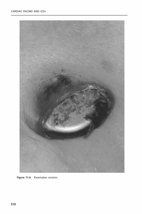
CARDIAC PACING AND ICDS
510
Figure 11.4. Pacemaker erosion.
the generator. It may also indicate lead or insulation fracture close to the musclelayer. Frequently no problem is identifiable, but the situation may be correctedby reprogramming to a lower output to avoid invasive revision to a bipolarsystem. Reduction of voltage is often effective in eliminating muscle stimula-tion—far more so than reduction of pulse width duration.
Diaphragmatic stimulation, if present, is usually apparent on physical exam-ination but rarely requires fluoroscopy for confirmation.This problem is becom-ing more frequent with the use of biventricular pacing systems. As mentionedpreviously, it may indicate direct stimulation of the diaphragm through a thinventricular wall, or, less commonly, through a perforated ventricle. In the formercase, reduction of output may alleviate the problem.Another cause for diaphrag-matic stimulation (right-sided) is phrenic nerve stimulation with a misplaced ordislodged atrial or ventricular lead. Depending on which lead is responsible, thecorrective approach may entail inactivation of the atrial channel, reduction ofatrial output, or re-positioning of the displaced lead.
Other important aspects of the physical examination include vital signs,with particular emphasis on pulse and blood pressure. The latter may vary sig-nificantly as a function of pacing mode (e.g.,VVI versus DDD) or pacing rate.Neck veins should be evaluated for the presence of cannon A waves; cardiacexamination should confirm paradoxical splitting of the second heart sound inmost cases of right ventricular pacing, and should exclude the presence of apericardial friction rub suggestive of cardiac perforation. The arm ipsilateral tothe lead insertion site should be examined for edema, perhaps reflecting venousthrombosis which is usually a spontaneously resolving phenomenon and rarelyresponsible for thromboembolism. Arm elevation is often helpful while endoge-nous thrombolysis and recruitment of collateral circulation takes place. If symp-toms are more marked, short-term anticoagulation with warfarin may speed theprocess. Edema coupled with inflammation may, less commonly, represent agouty attack precipitated by the recent surgical implantation of a pacer system.
Physical manipulation of the pacer system should be undertaken to evalu-ate the integrity of the leads and their connections to the generator can. Rarely,inversion of the generator can lead to myopectoral stimulation and/or loss ofcapture in unipolar systems.This may result because the generator was implantedwith the uninsulated side down or because the patient has reversed the can by“twiddling.”19
In rate-adaptive systems dependent on sensing vibration, the can may betapped to demonstrate increases in the pacing rate.Traction applied to the gen-erator may expose a previously unsuspected malconnection or lead fracture andresult in loss of capture or myopectoral stimulation. Confirmation of continuedcapture should be made with the patient in erect as well as supine position incases where inadequate or insufficient lead “slack” may be present. Myopoten-tial inhibition in single-chamber systems or myopotential triggering of ventric-ular pacing in dual-chamber systems may be elicited by various movements suchas abduction of the arm ipsilateral to the generator. This is ordinarily an issueonly for unipolar systems.The ability to observe real time intracardiac signals as
FOLLOW-UP ASSESSMENTS OF THE PACEMAKER PATIENT
511
well as the universal adaptation of marker channels has greatly eased this eval-uation. If myopotential inhibition is elicited and clinically significant, re-programming to a reduced sensitivity, to an asynchronous pacing mode, or to a triggered pacing mode may be undertaken to ensure continuous pacing in thepacer-dependent patient. Consideration of changing the unipolar system to abipolar system is another option. Carotid sinus massage is another physicalmaneuver that may be employed to induce slowing to the lower rate limit,thereby confirming the ability of the pacemaker to capture. Rarely, carotidmassage–induced slowing of the sinus node may be useful in dual-chambersystems to differentiate supraventricular tachycardia from physiological sinustachycardia with ventricular tracking near the upper rate limit.
RADIOGRAPHYThe chest radiograph (posteroanterior and lateral using the dorsal spine tech-nique) remains an important feature of the pacemaker follow-up evaluation,conveying a wealth of information.20 Following implant, it serves to delineatelead positioning and screw-tip advancement in active fixation leads. Lead dislo-cation is rare beyond the first month after implantation. Subsequent radiographsmay be scheduled on a periodic basis or only if specific questions are to beaddressed.
In particular, lead conductor fractures may sometimes be identified in casesof lead failure in the setting of elevated lead impedance. These typically occurat sites of acute angulation or at sites of increased external stress such as thefirst rib-clavicular junction in leads placed via subclavian vein puncture or atanchoring sites if a protective sleeve was not applied at the time of implant.Fluoroscopy, in conjunction with traction on the lead and generator, may berequired to delineate the fracture. Previously, a manufacturer’s advisory on poten-tial fracture of an inner J-shaped retention wire has recommended periodic cine-fluoroscopy to evaluate for fracture in certain active fixation J-shaped atrial leads(Telectronics Accufix series). The venous insertion site may be apparent on thefilm; jugular venous cutdown, for example, entails lead entry superior to theclavicle. Anatomic variants (such as persistent left superior vena cava) may alsobe appreciated. Clues to the polarity of the lead(s) may also be appreciated byanalyzing either the distal tip for presence of a ring electrode or the headerblock, though whether the generator is actually programmed to bipolar orunipolar remains to be determined. Examination of the connector block maydisclose retraction of the lead pin.
The generator may also be examined for position and, importantly, to iden-tify the specific model in patients with an unknown system.Various radiographicidentification codes exist that are manufacturer-specific and facilitate recogni-tion of the specific device in question (Fig. 11.5). Comprehensive referencesexist to assist in this process.21 Older systems not employing such radiographiccodes may be identified on the basis of generator shape or battery configura-tion on the radiograph.
CARDIAC PACING AND ICDS
512

ELECTROCARDIOGRAPHY AND MAGNET APPLICATIONIt is beyond the scope of this chapter to provide a detailed discussion of pace-maker electrocardiography. Rather, a general approach to the use of electrocar-diography in assessing pacemaker functioning will be addressed. The 12-leadelectrocardiogram, both with and without pacing, is a useful tool in pacemakerfollow-up assessments. Aside from confirming the pacer’s ability to sense andcapture, the electrocardiogram can provide important information on leadintegrity and position.22 For example, the typical morphology of a right ven-tricular paced complex is that of left bundle branch block, whereas right bundlebranch block morphology may suggest left ventricular pacing, whether inten-tional (e.g., epicardial wires) or otherwise (e.g., perforation). A superior axis iscommon in leads in the RV apex while intermediate or inferiorly directed axisare suggestive of leads high on the septum or in the outflow tract.
Although multiprogrammability and telemetered data through the pro-grammer have supplanted magnet application for detailed pacemaker analysis inmost cases, magnet application remains an important aspect of pacemaker eval-uation. In the absence of a programmer, magnet application with electrocardio-graphic monitoring confirms the ability to capture a cardiac chamber during
FOLLOW-UP ASSESSMENTS OF THE PACEMAKER PATIENT
513
Figure 11.5. Radiographic identification of a pacer generator has been facilitated by theuse of device-specific identification codes. The code appears horizontally in the rightupper corner of the device. The code “PJD” following the Medtronic logo identifies thedevice as a Medtronic Sigma 303 pacemaker (insert).
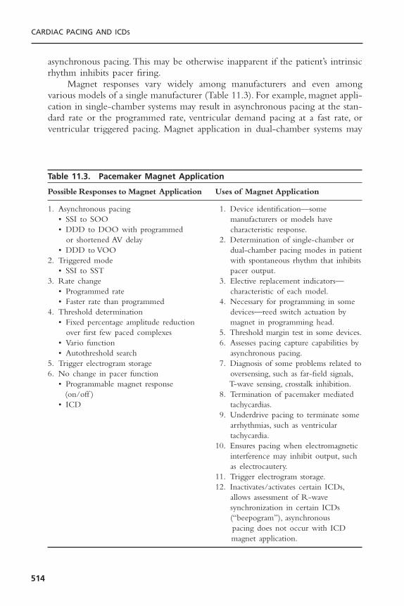
asynchronous pacing.This may be otherwise inapparent if the patient’s intrinsicrhythm inhibits pacer firing.
Magnet responses vary widely among manufacturers and even amongvarious models of a single manufacturer (Table 11.3). For example, magnet appli-cation in single-chamber systems may result in asynchronous pacing at the stan-dard rate or the programmed rate, ventricular demand pacing at a fast rate, orventricular triggered pacing. Magnet application in dual-chamber systems may
CARDIAC PACING AND ICDS
514
Table 11.3. Pacemaker Magnet Application
Possible Responses to Magnet Application Uses of Magnet Application
1. Asynchronous pacing 1. Device identification—some • SSI to SOO manufacturers or models have • DDD to DOO with programmed characteristic response.
or shortened AV delay 2. Determination of single-chamber or • DDD to VOO dual-chamber pacing modes in patient
2. Triggered mode with spontaneous rhythm that inhibits• SSI to SST pacer output.
3. Rate change 3. Elective replacement indicators—• Programmed rate characteristic of each model.• Faster rate than programmed 4. Necessary for programming in some
4. Threshold determination devices—reed switch actuation by • Fixed percentage amplitude reduction magnet in programming head.
over first few paced complexes 5. Threshold margin test in some devices.• Vario function 6. Assesses pacing capture capabilities by • Autothreshold search asynchronous pacing.
5. Trigger electrogram storage 7. Diagnosis of some problems related to6. No change in pacer function oversensing, such as far-field signals,
• Programmable magnet response T-wave sensing, crosstalk inhibition.(on/off ) 8. Termination of pacemaker mediated
• ICD tachycardias.9. Underdrive pacing to terminate some
arrhythmias, such as ventricular tachycardia.
10. Ensures pacing when electromagnetic interference may inhibit output, such as electrocautery.
11. Trigger electrogram storage.12. Inactivates/activates certain ICDs,
allows assessment of R-wave synchronization in certain ICDs (“beepogram”), asynchronous pacing does not occur with ICD magnet application.
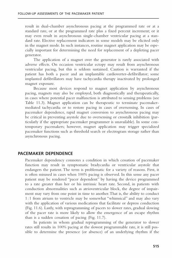
result in dual-chamber asynchronous pacing at the programmed rate or at astandard rate, or at the programmed rate plus a fixed percent increment; or itmay even result in asynchronous single-chamber ventricular pacing at a stan-dard rate. Elective replacement indicators in some models may be elicited onlyin the magnet mode. In such instances, routine magnet application may be espe-cially important for determining the need for replacement of a depleting pacergenerator.
The application of a magnet over the generator is rarely associated withadverse effects. On occasion ventricular ectopy may result from asynchronousventricular pacing, but this is seldom sustained. Caution is warranted if thepatient has both a pacer and an implantable cardioverter-defibrillator; someimplanted defibrillators may have tachycardia therapy inactivated by prolongedmagnet exposure.
Because most devices respond to magnet application by asynchronouspacing, magnets may also be employed, both diagnostically and therapeutically,in cases where potential pacer malfunction is attributed to sensing problems (seeTable 11.3). Magnet application can be therapeutic to terminate pacemaker-mediated tachycardia or to restore pacing in cases of oversensing. In cases ofpacemaker dependence, rapid magnet conversion to asynchronous pacing maybe critical in preventing asystole due to oversensing or crosstalk inhibition (par-ticularly if the appropriate pacemaker programmer is unavailable). In some con-temporary pacemakers; however, magnet application may trigger specializedpacemaker functions such as threshold search or electrogram storage rather thanasynchronous pacing.
PACEMAKER DEPENDENCEPacemaker dependency connotes a condition in which cessation of pacemakerfunction may result in symptomatic bradycardia or ventricular asystole thatendangers the patient. The term is problematic for a variety of reasons. First, itis often misused in cases when 100% pacing is observed. In this sense any pacerpatient may be rendered “pacer dependent” by having the device programmedto a rate greater than her or his intrinsic heart rate. Second, in patients withconduction abnormalities such as atrioventricular block, the degree of impair-ment may vary from one point in time to another.That is, the ability to conduct1 :1 from atrium to ventricle may be somewhat “whimsical” and may also varywith the application of various medications that facilitate or depress conduction(Fig. 11.6). Lastly, with reprogramming of pacers to slower rates, gradual slowingof the pacer rate is more likely to allow the emergence of an escape rhythmthan is a sudden cessation of pacing (Fig. 11.7).
In patients in whom gradual reprogramming of the generator to slowerrates still results in 100% pacing at the slowest programmable rate, it is still pos-sible to determine the presence (or absence) of an underlying rhythm if the
FOLLOW-UP ASSESSMENTS OF THE PACEMAKER PATIENT
515
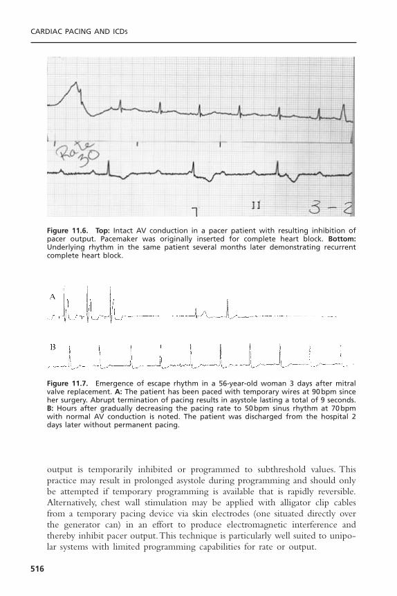
output is temporarily inhibited or programmed to subthreshold values. Thispractice may result in prolonged asystole during programming and should onlybe attempted if temporary programming is available that is rapidly reversible.Alternatively, chest wall stimulation may be applied with alligator clip cablesfrom a temporary pacing device via skin electrodes (one situated directly overthe generator can) in an effort to produce electromagnetic interference andthereby inhibit pacer output.This technique is particularly well suited to unipo-lar systems with limited programming capabilities for rate or output.
CARDIAC PACING AND ICDS
516
Figure 11.6. Top: Intact AV conduction in a pacer patient with resulting inhibition ofpacer output. Pacemaker was originally inserted for complete heart block. Bottom:Underlying rhythm in the same patient several months later demonstrating recurrentcomplete heart block.
Figure 11.7. Emergence of escape rhythm in a 56-year-old woman 3 days after mitralvalve replacement. A: The patient has been paced with temporary wires at 90bpm sinceher surgery. Abrupt termination of pacing results in asystole lasting a total of 9 seconds.B: Hours after gradually decreasing the pacing rate to 50bpm sinus rhythm at 70bpmwith normal AV conduction is noted. The patient was discharged from the hospital 2days later without permanent pacing.
PROGRAMMERSPacemaker programmers are complex devices with which the pacemaker physi-cian must be thoroughly familiar.8 Pacemaker programmers enable both pro-grammability and telemetry of a host of data including programming commands,administrative data, programmed data, measured data, and diagnostic data. Allprogrammers, independent of the manufacturer, share certain architectural fea-tures. All modern programmers are computer based. There is an input sectionthat allows operator interface with the computer programmer via a keyboard,light pen, and/or touch-sensitive screen. There is a telemetry interface associ-ated with the programmer usually in the form of a handheld wand that trans-mits signals to and receives data from the pulse generator. The programmer is also associated with a printer for hardcopy printouts of pacemaker data.The printer may be physically integrated with the programmer or a separatecomponent.
The three electromagnetic wave modalities that have enabled couplingbetween programmer and pacer generator have been magnetic coupling—appli-cation of a continuous or pulsed magnetic field that is detected by the gener-ator’s reed switch; inductive coupling—detection of pulsed magnetic fieldsthrough an antenna coil which then induces current flow that is detected as a coding scheme; and radiofrequency waves.23 Radiofrequency energy allows for the most rapid transmission of a large amount of information through highfrequency waves emitted by the programmer’s antenna and received by the generator’s antenna. The carrier frequencies depend upon the manufacturer.
Spurious programming remains a problem that may present in a variety offorms. “Phantom programming” refers to the reprogramming of a device byanother physician unbeknownst to the original physician programmer. “Dys-programming” is spurious programming due to an anomalous interferencesource such as electrocautery. “Misprogramming” is reprogramming of a pacerby a programmer in unanticipated fashion due to faulty program emissioncounts. Rarely, “cross-programming” may be observed as the unpredictablereprogramming of one manufacturer’s pacemaker by another manufacturer’s pro-grammer. For this reason a pacemaker must only be interrogated and pro-grammed with the specific manufacturer’s programmer.
TELEMETRY, STORED AND REAL-TIME DATAPacemaker follow-up assessments can be performed efficiently using a system-atic approach to interrogation and threshold testing (see Fig. 11.1). Even beforeany reprogramming is undertaken or thresholds are determined, the deviceshould be interrogated to document the current programmed settings. Allmodern devices have such telemetry available. It should be emphasized thatindependent confirmation of such parameters as mode and rate should be madeelectrocardiographically after all interventions, because telemetry will not alwaysreflect true programmed settings, although this is rare. This is particularly true
FOLLOW-UP ASSESSMENTS OF THE PACEMAKER PATIENT
517

in the case of pacer systems that have come into contact with extreme envi-ronmental noise (such as electrocautery or defibrillation) causing subsequentresetting of the device or pacer malfunction—in these cases, what you see (viatelemetry) is not always what you get. The ability to undertake telemetry, as inthe case of programming, is device-specific and requires manufacturer-specificprogrammers and/or modules. Inability to perform telemetry has several poten-tial explanations including the wrong programmer has been used, the program-mer is correct but lacks software updates to communicate with the presentmodel, the device is an older model incapable of providing telemetry, the devicehas a circuit malfunction24 or is at end of life.
The retrieval of stored and real-time data is an important part of eachfollow-up visit. When obtainable, real-time telemetry of measured data such asbattery voltage or lead impedance may prove quite useful in diagnosing prob-lems with impending battery depletion or lead integrity, respectively (Fig.11.8).25–31 A very low telemetered lead impedance may suggest problems with
CARDIAC PACING AND ICDS
518
Figure 11.8. Graphic 6-month trend report of atrial and ventricular electrogram ampli-tudes, pacing lead and high voltage lead impedances in a Guidant ICD. From August toDecember, high ventricular lead impedances (open circle) were documented (arrow) butreturned to normal at the time of the interrogation. The patient was demonstrated tohave a fractured ventricular lead.
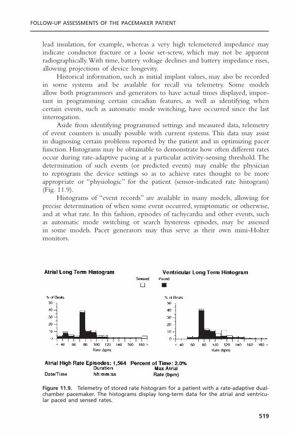
lead insulation, for example, whereas a very high telemetered impedance mayindicate conductor fracture or a loose set-screw, which may not be apparentradiographically.With time, battery voltage declines and battery impedance rises,allowing projections of device longevity.
Historical information, such as initial implant values, may also be recordedin some systems and be available for recall via telemetry. Some models allow both programmers and generators to have actual times displayed, impor-tant in programming certain circadian features, as well as identifying whencertain events, such as automatic mode switching, have occurred since the lastinterrogation.
Aside from identifying programmed settings and measured data, telemetryof event counters is usually possible with current systems. This data may assistin diagnosing certain problems reported by the patient and in optimizing pacerfunction. Histograms may be obtainable to demonstrate how often different ratesoccur during rate-adaptive pacing at a particular activity-sensing threshold. Thedetermination of such events (or predicted events) may enable the physician to reprogram the device settings so as to achieve rates thought to be more appropriate or “physiologic” for the patient (sensor-indicated rate histogram)(Fig. 11.9).
Histograms of “event records” are available in many models, allowing forprecise determination of when some event occurred, symptomatic or otherwise,and at what rate. In this fashion, episodes of tachycardia and other events, suchas automatic mode switching or search hysteresis episodes, may be assessed in some models. Pacer generators may thus serve as their own mini-Holter monitors.
FOLLOW-UP ASSESSMENTS OF THE PACEMAKER PATIENT
519
Figure 11.9. Telemetry of stored rate histogram for a patient with a rate-adaptive dual-chamber pacemaker. The histograms display long-term data for the atrial and ventricu-lar paced and sensed rates.

Real-time intracardiac electrograms and marker channels may be available,depending on the system used; they facilitate the physician’s ability to diagnoseappropriate, or inappropriate, pacer function.28 The size of the intracardiac elec-trograms may give the pacer physician a rough idea of the sensing capabilitiesof the system and may also delineate the strength of far-field signals.With somedevices, the patient may freeze and store electrograms with external magnetapplication during symptomatic events or the device may automatically storeelectrograms in response to high heart rates (Fig. 11.10).This corresponds to anevent monitor function of the device. The clinical utility of intracardiac elec-trograms includes identifying retrograde conduction, measuring ventriculoatrialconduction time, assisting rhythm identification, evaluating unusual sensing phe-nomena, evaluating lead connector integrity, assisting threshold determinations,and evaluating myopotential sensing.
Potentially more useful are marker channels, which denote when a partic-ular channel (atrial or ventricular) is sensing activity or emitting a paced output(Fig. 11.11). By telling the physician what the pacer is “seeing and doing,”certain phenomena, such as crosstalk inhibition, may be more easily defined.Event markers do, however, have their limitations. They describe pacer behav-ior but not its appropriateness; a stimulus output report does not necessarilyimply capture.
SENSING AND PACING THRESHOLDSFor manual sensing threshold determination, the device should first be re-programmed below the intrinsic rate to assess sensing. In single-chamber devices,ventricular sensing thresholds may be determined by then decreasing sensitivity(i.e., increasing the millivolt values) in the VVI mode to determine at what value
CARDIAC PACING AND ICDS
520
Figure 11.10. Stored atrial (top) and ventricular (bottom) electrograms from a pace-maker with automated electrogram capture triggered by a high ventricular rate. Thepatient experienced syncope at the time the electrograms were recorded. The docu-mentation of AV dissociation is diagnostic of ventricular tachycardia.

pacer output is no longer inhibited. The same approach may be applied forestablishing atrial-sensing thresholds. The triggered modes may also be used intheir respective chambers to determine sensing thresholds. Failure to trigger apacemaker spike at a given sensitivity value indicates undersensing (Fig. 11.12).Alternatively, triggered pacing by signals other than the P wave or QRS, suchas T waves or myopotentials, indicate oversensing. In dual-chamber systems, atrialsensing can be confirmed by programming to a P-wave synchronous ventricu-lar triggered mode, shortening the AV interval so as to trigger ventricular pacing,and reducing atrial sensitivity progressively until paced ventricular events nolonger result.Ventricular sensing can either be checked in a VVI mode with the
FOLLOW-UP ASSESSMENTS OF THE PACEMAKER PATIENT
521
Figure 11.11. Surface ECG, atrial (AEGM) and ventricular (VEGM) intracardiac electro-grams, and marker channel (bottom) demonstrating “noise” and oversensing on theatrial lead of a Guidant ICD. This resulted from an insulation break from subclavian crush.
Figure 11.12. Atrial triggered pacing mode. Top: Maximal sensitivity of 0.5mV atrialsensing is appropriate. Bottom: With reduction of atrial sensitivity to 5.0mV there is afailure of atrial sensing with atrial spikes that do not coincide with native P waves.
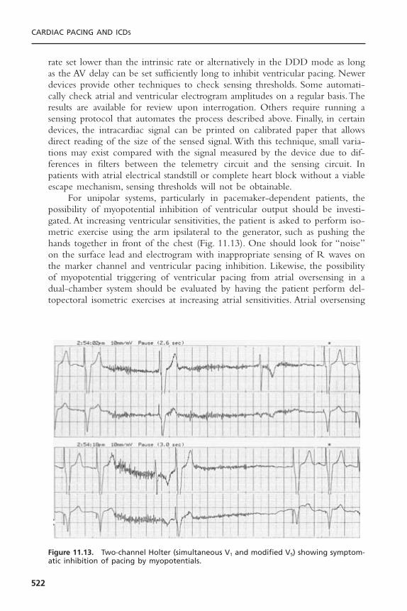
rate set lower than the intrinsic rate or alternatively in the DDD mode as longas the AV delay can be set sufficiently long to inhibit ventricular pacing. Newerdevices provide other techniques to check sensing thresholds. Some automati-cally check atrial and ventricular electrogram amplitudes on a regular basis.Theresults are available for review upon interrogation. Others require running asensing protocol that automates the process described above. Finally, in certaindevices, the intracardiac signal can be printed on calibrated paper that allowsdirect reading of the size of the sensed signal. With this technique, small varia-tions may exist compared with the signal measured by the device due to dif-ferences in filters between the telemetry circuit and the sensing circuit. Inpatients with atrial electrical standstill or complete heart block without a viableescape mechanism, sensing thresholds will not be obtainable.
For unipolar systems, particularly in pacemaker-dependent patients, thepossibility of myopotential inhibition of ventricular output should be investi-gated. At increasing ventricular sensitivities, the patient is asked to perform iso-metric exercise using the arm ipsilateral to the generator, such as pushing thehands together in front of the chest (Fig. 11.13). One should look for “noise”on the surface lead and electrogram with inappropriate sensing of R waves onthe marker channel and ventricular pacing inhibition. Likewise, the possibilityof myopotential triggering of ventricular pacing from atrial oversensing in adual-chamber system should be evaluated by having the patient perform del-topectoral isometric exercises at increasing atrial sensitivities. Atrial oversensing
CARDIAC PACING AND ICDS
522
Figure 11.13. Two-channel Holter (simultaneous V1 and modified V5) showing symptom-atic inhibition of pacing by myopotentials.

of myopotential or far-field R waves are frequent causes of inappropriate modeswitching. In general, the chronic atrial and ventricular sensitivities settingsshould be set to a twofold to fourfold safety margin unless oversensing occurs(i.e., for an atrial sensing threshold of 2mV, a sensitivity setting of 0.5 to 1.0mV would be appropriate).
The pacing threshold determination is an important feature of pacerfollow-up evaluations because generator longevity may be significantly enhancedif the output can be programmed to the lowest value that will provide an ade-quate safety margin for pacing. Particular longevity may be obtained if outputscan be programmed to 2.5V, i.e., less than the lithium-iodine battery voltage of2.8V. At this output, the energy inefficient voltage doubling circuit can beavoided. Further decreases in output beyond this point provide diminishingenergy savings. In practice, doubling the voltage threshold (at a pulse width of0.4 or 0.5 milliseconds) or tripling the pulse width threshold (as long as lessthan 0.3 milliseconds) usually will provide an adequate safety margin. Energyconsumption is directly proportional to the pulse width but increases with thesquare of voltage. If tripling the pulse width results in an interval less than 0.9milliseconds, this is usually more energy efficient than doubling the voltage. Pro-gramming larger safety margins is typical immediately after implant to allow forthe usual post-implant threshold increases. This process is almost always com-plete by 2 to 3 months allowing chronic thresholds to be programmed at thatpoint. Programming larger safety margins should also be considered in the ven-tricular channel of pacemaker-dependent patients given the possibility of lateunexpected threshold rises.32
Determination of pacing thresholds should be made for both chamberswhere applicable.33 In patients with intact AV conduction, determination of atrialstimulation threshold is easiest measured in the AAI mode with the pacing rateset 10 to 20bpm above the intrinsic rate. Atrial output (or pulse width) is pro-gressively lowered until a QRS complex is “dropped” indicating loss of atrialcapture. In patients with AV block, atrial capture must be measured in a DDDmode. The threshold may then be determined by noting the loss of a P waveon a surface tracing or the appearance of atrial sensed events on a markerchannel or spontaneous atrial signal on an electrogram tracing. The latter twofindings indicate return of spontaneous sinus node function after loss of atrialcapture. Ventricular stimulation thresholds are most cleanly performed in VVImode. DDD mode may also be used as an alternative particularly in patientswho feel poorly with the loss of AV synchrony with VVI pacing.The AV delaymust be set sufficiently short to “force” ventricular pacing and minimize fusionand pseudo-fusion which can obscure detection of loss of ventricular captureand result in falsely low perceived stimulation threshold. In pacemaker-dependentpatients, loss of ventricular capture may result in asystole. Fortunately, mostmodern programmers permit rapid restoration of preprogrammed outputs withtemporary pacing modes or automated threshold algorithms.The operator mustremain vigilant though to terminate the test immediately after loss of captureis first noted.
FOLLOW-UP ASSESSMENTS OF THE PACEMAKER PATIENT
523

Automaticity is a feature that has been applied to a number of pacemakerparameters to allow for device regulation without the need for continual clini-cian input.This is particularly the case with ventricular capture determinations.To date, auto-capture algorithms have been limited to the ventricle due to therelative ease of measuring the large evoked response with capture; however,devices capable of automatically measuring atrial capture are available as well.In some devices, the generator may be programmed to automatically determinethe pacing threshold continuously or at periodic intervals and reset the outputso as to ensure an adequate safety margin and simultaneously optimize devicelongevity. Certain devices which check capture on a beat-to-beat basis allowprogramming the output to as little as 0.25V over the stimulation threshold.This option is being used increasingly to facilitate device follow-up.34
Programmability of polarity has become increasingly available in currentpacemakers and, unfortunately, is not infrequently required. Problems with insu-lation defects in certain polyurethane leads subject to the “subclavian crush”syndrome, resulting in low impedance values, may be temporarily addressed byre-programming from bipolar to unipolar mode. This maneuver generally willincrease the lead impedance in these situations and prevent loss of capture andpossible undersensing, but will not prevent oversensing from make–break elec-trical transients arising from contact between the two conductors. Ultimately,lead replacement is required in the pacer-dependent patient. Occasionally, pacingor sensing thresholds will be significantly better in one polarity compared tothe other. This may be helpful in the setting of marginal threshold values.General guidelines for chronic programming of common pacemaker parametersare given in Table 11.4.
THE ATRIOVENTRICULAR INTERVALRecent data35 suggesting that right ventricular pacing may worsen symptoms ofcongestive heart failure in those with underlying cardiomyopathy has re-focusedattention on appropriate programming of the AV interval. Certainly, in thosewith diminished LV function, one should make attempts to prolong the AVdelay sufficiently to minimize RV pacing. This can be accomplished with pro-gramming a long fixed AV delay or programming “on” an AV search hysteresisfeature which is being increasingly incorporated into new devices. With thisfeature, a backup AV interval is set as well as a further delay which is added to the programmed value allowing additional time to encourage native con-duction. If no intrinsic R wave has been sensed by the end of the summedinterval, the programmed “physiologic” AV delay will become active but withperiodic searches for native conduction. Programming the device to DDI(R)mode is sometimes worthwhile as well. In contrast, patients with normal LVfunction are rarely able to distinguish between native conduction and P wavesynchronous pacing. Nevertheless, the above techniques to minimize ventricu-lar pacing may still be worthwhile if only to maximize battery duration.However, there is clearly an AV delay sufficiently long that the benefits of
CARDIAC PACING AND ICDS
524
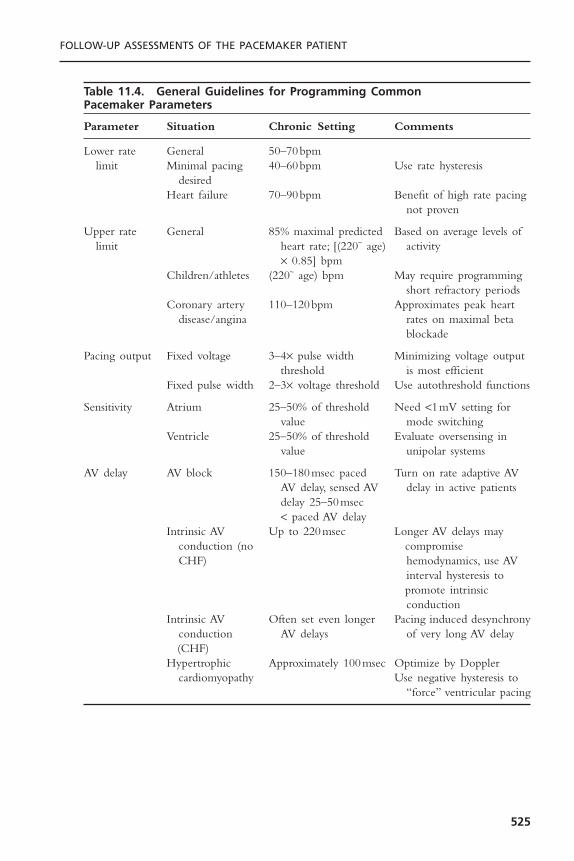
FOLLOW-UP ASSESSMENTS OF THE PACEMAKER PATIENT
525
Table 11.4. General Guidelines for Programming Common Pacemaker Parameters
Parameter Situation Chronic Setting Comments
Lower rate General 50–70bpmlimit Minimal pacing 40–60bpm Use rate hysteresis
desiredHeart failure 70–90bpm Benefit of high rate pacing
not proven
Upper rate General 85% maximal predicted Based on average levels of limit heart rate; [(220~ age) activity
¥ 0.85] bpmChildren/athletes (220~ age) bpm May require programming
short refractory periodsCoronary artery 110–120bpm Approximates peak heart
disease/angina rates on maximal beta blockade
Pacing output Fixed voltage 3–4¥ pulse width Minimizing voltage output threshold is most efficient
Fixed pulse width 2–3¥ voltage threshold Use autothreshold functions
Sensitivity Atrium 25–50% of threshold Need <1mV setting for value mode switching
Ventricle 25–50% of threshold Evaluate oversensing in value unipolar systems
AV delay AV block 150–180msec paced Turn on rate adaptive AV AV delay, sensed AV delay in active patientsdelay 25–50msec < paced AV delay
Intrinsic AV Up to 220msec Longer AV delays may conduction (no compromise CHF) hemodynamics, use AV
interval hysteresis topromote intrinsic conduction
Intrinsic AV Often set even longer Pacing induced desynchrony conduction AV delays of very long AV delay(CHF)
Hypertrophic Approximately 100msec Optimize by Dopplercardiomyopathy Use negative hysteresis to
“force” ventricular pacing

inhibiting ventricular pacing are outweighed by the adverse hemodynamiceffects which can result with marked first degree block. Much of this detri-mental effect may be linked to atrial contraction occurring during or immedi-ately after ventricular systole creating a “pseudo-pacemaker syndrome.” Certainstudies have demonstrated that this detrimental effect is seen with PR intervalsof greater than 220 milliseconds.36 In occasional patients who continue to com-plain of breathlessness after a pacemaker is implanted, an attempt at AV opti-mization using Doppler echocardiography or impedance cardiography may bewarranted. Both AV as well as LV/RV optimization is a subject of particularinterest in those with bi-ventricular pacemakers. Traditional mitral inflow andaortic outflow Doppler measurements as well as newer tissue Doppler tech-niques are being investigated.37,38
In contrast to the previous situations, there are also situations in which ven-tricular pacing is desired. This is particularly true when dual-chamber pace-makers are placed for symptom relief in those with hypertrophic obstructivecardiomyopathy. Programming a short fixed AV delay is one option althoughmore sophisticated algorithms such as negative AV interval hysteresis can bequite effective in allowing for the longest AV interval that still provides 100%ventricular pacing. Patients with biventricular pacemakers represent anothergroup where continuous ventricular pacing is desired. This is often difficultwhen these patients develop rapid atrial fibrillation. New algorithms are beingdeveloped to assist in this situation. One such algorithm automatically increasesthe ventricular pacing rate after every sensed ventricular event.Another providesa “triggered” mode where each sensed ventricular beat immediately results inLV pacing resulting in a fused QRS complex which is more synchronized thanthe intrinsic beat would be alone. Finally, in patients with a “traditional” dual-chamber pacemaker, underlying cardiomyopathy and a baseline right bundlebranch block, biventricular pacing can often be simulated. To accomplish this,one carefully programs the AV delay so as to create fusion between the RVpaced complex and the native QRS (which, due to the RBBB, is activating theleft ventricle first) and thus, create some measure of re-synchrony.
A differential AV delay is now incorporated into virtually all modern pace-makers. This allows for programming of a shorter AV delay for the sensed AVinterval (SAV) compared with the paced AV interval (PAV). This accounts forthe fact that the pacemaker does not recognize a sensed atrial event (and startthe SAV timer) until atrial depolarization is well under way.The differential AVdelay thus keeps the time between atrial and ventricular contraction constantregardless of the presence of atrial pacing. A differential value of 25 to 40 milli-seconds is considered appropriate. Most pacemakers also now have a rate respon-sive AV delay feature. This provides for a shortening of the AV interval duringexercise mimicking the normal positive dromotropic effect seen in those withnormal AV conduction. This feature provides a hemodynamic benefit as well as allow for the programming of a higher maximum tracking rate. This feature should ordinarily be programmed “on” in those with AV conductiondisturbances.
CARDIAC PACING AND ICDS
526

SPECIAL CONSIDERATIONS IN DUAL-CHAMBER SYSTEMSIn dual-chamber systems several problems may require evaluation during follow-up evaluations as the clinical situation arises. The possibility of cross talk; thatis, inappropriate sensing of the atrial pacing artifact on the ventricular channelresulting in ventricular pacing inhibition can be assessed by programming theventricular channel to highest sensitivity and the atrial output to its highest value(Fig. 11.14).The programmed rate should exceed the native rate so as to requirecontinuous atrial pacing, and the programmed AV interval should be shorterthan the native PR interval. The absence of cross talk inhibition at maximalatrial output and maximal ventricular sensitivity suggests that this problem isnot likely to be encountered at usual settings. Fortunately, cross talk is much lessof a problem with modern pulse generators that incorporate various techniquesto minimize this problem such as ventricular blanking periods and cross-talksensing windows. Assessment of this phenomenon should be undertaken cau-tiously in patients with heart block, because ventricular asystole may occur. Iden-tification of cross talk warrants re-programming, when possible, to lower atrialoutput or ventricular sensitivity, prolongation of ventricular blanking period, orconsideration of another mode such as VDD.
The propensity for pacemaker-mediated tachycardia (PMT) in the DDDmode may be explored by shortening the postventricular atrial refractory period
FOLLOW-UP ASSESSMENTS OF THE PACEMAKER PATIENT
527
A
B
Figure 11.14. Cross talk in a unipolar dual chamber pacemaker. Panel A: This patientwas referred for loss of capture on the ventricular lead. The ECG shows atrial pacing con-sistently but ventricular output on only the first cardiac cycle. Telemetry showed ven-tricular sensing within 40 to 60 milliseconds of the pacing output that inhibits ventricularpacing. After reducing atrial sensitivity from 2.8 to 5.6mV inhibition of ventricular outputwas corrected. This device did not have programmable postatrial pacing ventricularblanking intervals or safety pacing that would have also resolved the cross talk.

(PVARP) to its minimum and programming atrial output to subthreshold levels.If retrograde ventriculoatrial conduction is present, PMT may be observed if itis triggered by a spontaneous PVC or if loss of atrial capture occurs. In thelatter case, the AV sequential paced rhythm fails to capture the atrium but cap-tures the ventricle, with retrograde conduction leading to activation of theatrium and setting up PMT. PMT may be managed by decreasing the upperventricular tracking rate, extending the PVARP (which may limit the desiredupper tracking limit), changing to a nonatrial tracking mode such as DDI oractivating PMT intervention algorithms. These can include an increase in thePVARP after a PVC which will minimize the chance of initiating a PMT orperiodically “dropping” a ventricular paced beat with any tachycardia near theupper rate limit. This will terminate the tachycardia if it is indeed a PMT butonly create a brief pause if the rhythm were an intrinsic atrial rhythm that thepacemaker was tracking, i.e., sinus tachycardia. Many devices allow programmingof a rate-adaptive PVARP that shortens the PVARP at more rapid rates per-mitting a long PVARP at rest without unduly imposing limits on the upperrate.
Not infrequently, a patient with a dual-chamber device will present withnew onset atrial fibrillation or flutter.The atrial fibrillation or flutter waves maybe sensed and trigger rapid ventricular responses, often irregularly (Fig. 11.15).Automatic mode switching is a very important feature incorporated into manydual-chamber pacemakers for the management of atrial arrhythmias (Fig. 11.16).It allows reversion from dual-chamber pacing to single-chamber ventricularpacing (or to a non-atrial tracking mode such as DDI(R)) when atrial arrhyth-mias are recognized, and a return to dual-chamber mode when sinus rhythmhas been restored. In general, this algorithm works well, but occasional under-sensing of fibrillatory waves may result in frequent switches back to DDD mode
CARDIAC PACING AND ICDS
528
ECG
Marker
AEGM0.1mm/mV
Figure 11.15. Rhythm strip showing intermittent ventricular tracking of atrialflutter/atrial fibrillation resulting in irregular ventricular pacing near the upper rate limitin the DDD mode. At the start of the tracing, the device is in mode switch non-atrialtracking mode with a slow paced ventricular rate. At the first arrow, the device exitsmode switching to DDD mode because of atrial undersensing (MS on marker annota-tions). The second arrow identifies re-activation of mode switch behavior due to consis-tent atrial sensing with brief tracking at the upper rate limit. AEGM = atrial electrogram.
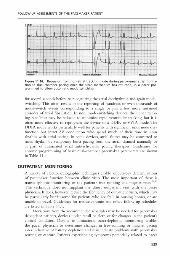
for several seconds before re-recognizing the atrial dysrhythmia and again mode-switching. This often results in the reporting of hundreds or even thousands ofmode-switch events corresponding to a single or just a few more sustainedepisodes of atrial fibrillation. In non–mode-switching devices, the upper track-ing rate limit may be reduced to minimize rapid ventricular tracking, but it isoften more effective to reprogram the device to a DDIR or VVIR mode. TheDDIR mode works particularly well for patients with significant sinus node dys-function but intact AV conduction who spend much of their time in sinusrhythm with atrial pacing. In some devices, atrial flutter may be converted tosinus rhythm by temporary burst pacing from the atrial channel manually or as part of automated atrial antitachycardia pacing therapies. Guidelines forchronic programming of basic dual-chamber pacemaker parameters are shownin Table 11.4.
OUTPATIENT MONITORINGA variety of electrocardiographic techniques enable ambulatory determinationsof pacemaker function between clinic visits. The most important of these istranstelephonic monitoring of the patient’s free-running and magnet rates.29,30
This technique does not supplant the direct outpatient visit with the pacerphysician. It does, however, reduce the frequency of outpatient visits, which maybe particularly burdensome for patients who are frail, in nursing homes, or areunable to travel. Guidelines for transtelephonic and office follow-up schedulesare listed in Table 11.1.
Deviations from the recommended schedules may be needed for pacemakerdependent patients, devices under recall or alert, or for changes in the patient’sclinical condition. Despite its limitations, transtelephonic monitoring enables the pacer physician to determine changes in free-running or magnet pacing rates indicative of battery depletion and may indicate problems with pacemakersensing or capture. Patients experiencing symptoms potentially related to pacer
FOLLOW-UP ASSESSMENTS OF THE PACEMAKER PATIENT
529
Figure 11.16. Reversion from non-atrial tracking mode during paroxysmal atrial fibrilla-tion to dual-chamber pacing once the sinus mechanism has returned, in a pacer pro-grammed to allow automatic mode switching.

function or malfunction are encouraged to transmit their rhythm when they aresymptomatic, independent of the above scheduling guidelines.
As an extension of this approach, 24-hour Holter monitoring may be usefulfor uncovering problems with pacer malfunction that are potentially responsi-ble for a patient’s symptoms (Fig. 11.17).31 The approach is limited by samplingerror in patients with infrequent symptoms, as no abnormalities may be iden-tified if the patient is “having a good day.” Rather, the technique is more oftenuseful in demonstrating previously unsuspected and asymptomatic malfunctions,such as intermittent undersensing or myopotential triggering. Activity-relatedrate trends warranting reprogramming, particularly with dual-chamber or rate-adaptive pacing, may be observed with Holter monitoring.
Presently, all manufacturers of pacemakers and ICDs have recently releasedor will shortly release enhanced outpatient monitoring devices. These devicesoften take advantage of newer wireless technologies and the Internet. Thesesystems can “interrogate” the implanted device and provide information equiv-alent to that when interrogating a device in the office including stored elec-trograms from high rate events in pacemakers as well as printouts from VT/VFevents in defibrillators.39 Some monitoring devices can be placed on a night-stand in a patient’s bedroom and will communicate with the device wirelesslywithout the need for any patient involvement. Transmission can be automatedto occur at pre-ordained times or in response to trigger signals sent out by thedevice after specific events like defibrillator shocks or ERI being reached. Othermonitoring systems require the patient to hold the unit near their device. Thephysician can receive this information either via fax or on a secure website overthe Internet.40 While the technology is already available for the physician toremotely re-program the device, safety concerns limit access to this featurepresently. Similar to stand-alone programmers, manufacturers are using propri-etary technology and thus the chance for universal equipment appears remote.
CARDIAC PACING AND ICDS
530
Figure 11.17. Intermittent loss of ventricular capture documented on ambulatory Holtermonitoring.

ELECTIVE REPLACEMENT INDICATORSThe behavior of pacemakers approaching battery depletion is highly variableamong different manufacturers and even among different models from the samemaker. It is important to distinguish end-of-life (EOL) from ERI. The formerconnotes gross pacemaker malfunction or lack of function; the latter strives to indicate a time when generator replacement should be considered well inadvance of end of life.41,42 ERIs should be reached in the absence of pa-tient symptoms or electrocardiographically demonstrated abnormalities in free-running pacer function. Indeed, changes in behavior, such as in magnet rates,may occur years in advance of true end of life. ERIs are used to recommendgenerator change within a period of a few weeks to months. They are device-specific and may be found by consulting with the manufacturer or the physi-cian’s manual.When it is available, real-time telemetry of available battery voltageand impedance may be useful in confirming battery depletion, particularly asprogressive increases in battery impedance are observed. In most systems,however, changes in pacing rate are the predominant indicators of the need forelective replacement.
As the lithium iodine battery discharges, the internal impedance of thebattery to current flow increases. At or near EOL, transient high current drainfrom the battery may further reduce the output voltage.This may result in tem-porary or persistent loss of device function (Fig. 11.18). If near ERI, the reducedouput voltage may drop battery voltage below ERI levels, tripping the ERIbehavior. Some devices will revert from the ERI mode (unlatched behavior)once battery voltage has recovered. If the behavior is latched, the ERI modecan be canceled only by reprogramming the device. True ERI or EOL behav-ior must be distinguished from “power on reset” (POR) mode that results from
FOLLOW-UP ASSESSMENTS OF THE PACEMAKER PATIENT
531
Figure 11.18. Loss of capture during programmer head (magnet) application in a pace-maker at end of battery life. The pacemaker telemetry was non-functional. Three pacedbeats at 100bpm denote magnet application. With continued application of the pro-gramming head capture was lost due to increased current demand on the battery. A tem-porary pacemaker was in place anticipating such an occurrence.

loss or corruption of the pacemaker’s volatile electronic memory. POR modeis a simple backup pacing mode (typically VVI or VOO) that is stored in non-volatile, read-only memory and allows the device to function after loss of pro-grammable memory. The POR mode and ERI modes and rates of operationmay or may not be identical for a given device. If identical, POR may be dis-tinguished from ERI by a satisfactory battery voltage in POR and a low batteryvoltage in ERI. POR mode can be latched or unlatched. If battery voltage isnot available but POR is unlatched, the device may be reprogrammed to con-tinuous pacing at high output for 30 minutes (“battery stress test”). If ERI hasoccurred, the device will again revert to ERI; if POR has occurred, the pro-grammed function will continue.
A summary of pacemaker behavior throughout the stages of battery life isshown in Table 11.5.
SPECIAL SITUATIONS ENCOUNTERED BY THE PACEMAKER PATIENTThe pacer physician is often asked to evaluate a pacemaker patient beforesurgery. In addition to obtaining details from the history and physical examina-tion outlined previously, it is most essential to establish the degree of pacerdependence and, via telemetry, the current programmed settings. Operatingroom personnel including the surgeon, nursing staff, and anesthesiologists allneed to be aware of the presence of the device, the potential EMI encounteredin the operating room, and corrective techniques. An external defibrillator withtranscutaneous pacing capabilities should be easily accessible. Electrocautery,often required intraoperatively, may result in a variety of pacemaker phenom-ena. Electrocautery may cause transient inhibition of pacer output because ofoversensing of electromagnetic interference. If pacer dependence has beendemonstrated preoperatively, the device may be programmed to either an asyn-chronous mode or a triggered mode to preempt undue inhibition of paceroutput. If such programming is not possible, then a magnet may be taped overthe generator during the period of cautery. However, by activating the reedswitch, magnet application may make certain older pacemakers vulnerable tospurious re-programming. It is ideal to avoid electrocautery entirely if possible,especially near the pacer generator.The cautery grounding pad should be placedas far as possible from the generator and in a location where the vector fromthe electrocautery tip to the pad moves directly away from the pacemaker gen-erator. In addition, short bursts of cautery and use of bipolar cautery are rec-ommended.The major issue with an implantable cardiac defibrillator is the riskof oversensing noise resulting in inappropriate defibrillator shocks.
Both electrocautery and defibrillation can produce irreversible damage tothe generator. This is more likely in older devices that lack protective mecha-nisms such as zener diodes, which shunt energy away from the delicate devicecircuitry.They may also result in resetting of the generator to a backup or noise-reversion mode. Pacemaker interrogation with pacing and sensing thresholdsshould be performed before and after the surgical procedure. Recommendations
CARDIAC PACING AND ICDS
532
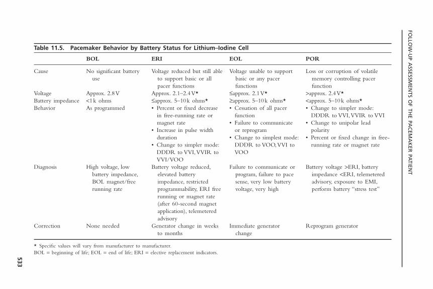
FOLLO
W-U
P ASSESSM
ENTS O
F THE PA
CEM
AK
ER PA
TIENT
533
Table 11.5. Pacemaker Behavior by Battery Status for Lithium–Iodine Cell
BOL ERI EOL POR
Cause No significant battery Voltage reduced but still able Voltage unable to support Loss or corruption of volatile use to support basic or all basic or any pacer memory controlling pacer
pacer functions functions functionVoltage Approx. 2.8V Approx. 2.1–2.4V* £approx. 2.1V* >approx. 2.4V*Battery impedance <1k ohms £approx. 5–10k ohms* ≥approx. 5–10k ohms* <approx. 5–10k ohms*Behavior As programmed • Percent or fixed decrease • Cessation of all pacer • Change to simpler mode:
in free-running rate or function DDDR to VVI,VVIR to VVImagnet rate • Failure to communicate • Change to unipolar lead
• Increase in pulse width or reprogram polarityduration • Change to simplest mode: • Percent or fixed change in free-
• Change to simpler mode: DDDR to VOO,VVI to running rate or magnet rateDDDR to VVI,VVIR to VOOVVI/VOO
Diagnosis High voltage, low Battery voltage reduced, Failure to communicate or Battery voltage >ERI, battery battery impedance, elevated battery program, failure to pace impedance <ERI, telemetered BOL magnet/free impedance, restricted sense, very low battery advisory, exposure to EMI,running rate programmability, ERI free voltage, very high perform battery “stress test”
running or magnet rate(after 60-second magnet application), telemetered advisory
Correction None needed Generator change in weeks Immediate generator Reprogram generatorto months change
* Specific values will vary from manufacturer to manufacturer.BOL = beginning of life; EOL = end of life; ERI = elective replacement indicators.
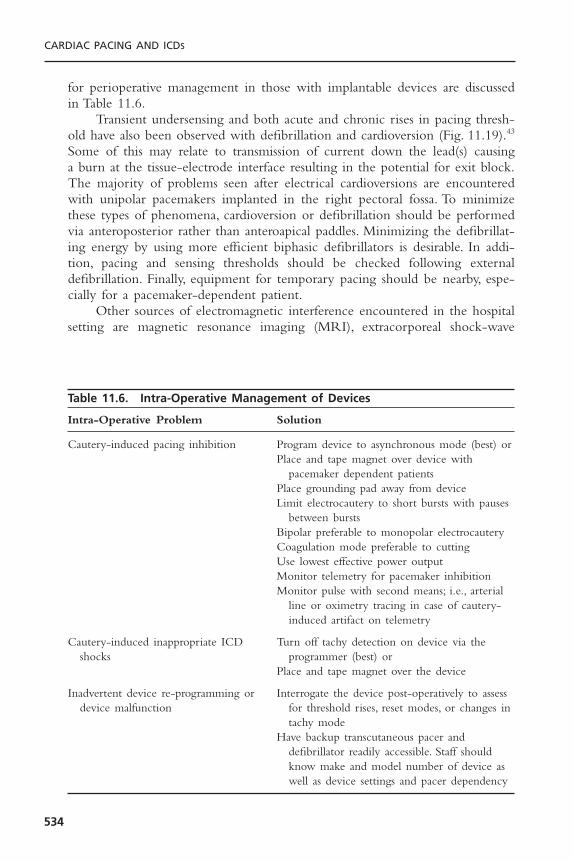
for perioperative management in those with implantable devices are discussedin Table 11.6.
Transient undersensing and both acute and chronic rises in pacing thresh-old have also been observed with defibrillation and cardioversion (Fig. 11.19).43
Some of this may relate to transmission of current down the lead(s) causing a burn at the tissue-electrode interface resulting in the potential for exit block.The majority of problems seen after electrical cardioversions are encounteredwith unipolar pacemakers implanted in the right pectoral fossa. To minimizethese types of phenomena, cardioversion or defibrillation should be performedvia anteroposterior rather than anteroapical paddles. Minimizing the defibrillat-ing energy by using more efficient biphasic defibrillators is desirable. In addi-tion, pacing and sensing thresholds should be checked following externaldefibrillation. Finally, equipment for temporary pacing should be nearby, espe-cially for a pacemaker-dependent patient.
Other sources of electromagnetic interference encountered in the hospitalsetting are magnetic resonance imaging (MRI), extracorporeal shock-wave
CARDIAC PACING AND ICDS
534
Table 11.6. Intra-Operative Management of Devices
Intra-Operative Problem Solution
Cautery-induced pacing inhibition Program device to asynchronous mode (best) orPlace and tape magnet over device with
pacemaker dependent patientsPlace grounding pad away from deviceLimit electrocautery to short bursts with pauses
between burstsBipolar preferable to monopolar electrocauteryCoagulation mode preferable to cuttingUse lowest effective power outputMonitor telemetry for pacemaker inhibitionMonitor pulse with second means; i.e., arterial
line or oximetry tracing in case of cautery- induced artifact on telemetry
Cautery-induced inappropriate ICD Turn off tachy detection on device via the shocks programmer (best) or
Place and tape magnet over the device
Inadvertent device re-programming or Interrogate the device post-operatively to assess device malfunction for threshold rises, reset modes, or changes in
tachy modeHave backup transcutaneous pacer and
defibrillator readily accessible. Staff should know make and model number of device as well as device settings and pacer dependency

lithotripsy, radiofrequency ablation, and radiation therapy. MRI presents a par-ticularly noxious environment for cardiac devices. Potential interactions includereed switch closure, pacing inhibition, inappropriate ICD discharges, and rapidpacing. The latter can be initiated either from the pulse generator or, indepen-dently, by the induction of current flow along the lead. Lead dislodgment orthe induction of torque on the generator itself remain possible, but with dimin-ishing amounts of ferrous material in recently constructed systems there is muchless rotational and translational forces brought to bear.44 In general, the presenceof a pacemaker or ICD should be considered a contraindication to MRI. Beforedevice placement, the implanter should give careful thought to the potentialneed for MRI and, when feasible, complete the imaging before implant. In veryrare situations, use of an MRI may be considered but only with close coordi-nation and discussion among electrophysiologist, radiologist, and patient. Factorsthat may decrease the likelihood of complications include use of less powerfulMRI machines, imaging of extremities (i.e., device not within gantry), carefulre-programming of device, thoughtful selection of appropriate spin sequences,
FOLLOW-UP ASSESSMENTS OF THE PACEMAKER PATIENT
535
Figure 11.19. Loss of capture in a VVI pacemaker following DC cardioversion for atrialfibrillation (Panel A). Panel B was obtained 3 minutes after the shock showing persistentloss of capture at the paced rate of 60bpm. The threshold increased transiently from 0.6to 3V, but returned to baseline within 10 minutes.

periprocedural monitoring, and restriction of scans to non–pacemaker-depen-dent patients.45
In the case of lithotripsy, distancing of the pacer from the focal point ofthe lithotripsy is recommended to avoid potential problems with undue inhi-bition of pacer output or irregular sensing.46 This is particularly true in activ-ity-sensing devices dependent on piezoelectric crystals. These crystals may becapable of oversensing shock waves and result in increased pacing rates; alter-natively, they may be susceptible to damage (e.g., crystal is shattered) from theshock waves. Current recommendations in this procedure are:
1. Patients with piezoelectric activity-sensing rate-responsive pacemakers shouldnot undergo lithotripsy if the device is implanted in the abdomen.
2. Patients with activity-sensing rate-adaptive pacemakers implanted in thethorax should have their rate-responsive features turned off.
3. The pulse generator must not be submerged below the water level in thetank.
4. Patients with implanted dual-chamber devices should be programmed to theVVI mode before lithotripsy.
Radiofrequency ablation is often undertaken in the EP lab to effect per-manent cure of various atrial and ventricular tachyarrhythmias.This energy canat times result in reprogramming the device to a reset mode, or transiently causeasynchronous pacing due to noise reversion or pacemaker inhibition.47 The lattercan be particularly relevant in the patient undergoing AV node catheter abla-tion, which results in complete heart block and pacemaker dependency (Fig.11.20). Re-programming the device to an asynchronous mode will prevent thisissue from arising. RF energy can result in spurious shocks in those with ICDs.Antitachycardia therapies should be programmed “off.” Rarely, threshold risesmay be observed.
Radiation therapy (e.g., for breast or lung cancer) to the chest may beunavoidable in certain patients with pacemakers. Ionizing radiation can result inrandom component failure and premature battery depletion. To minimize thisrisk, appropriate methods of shielding the generator and limiting the field ofradiation should be discussed with the radiation therapist. Damage may resultin sudden loss of output, alterations in programmed parameters, and raterunaway. In rare instances, a newly placed contralateral system or generator repo-sitioning using lead extenders should be considered. If included in the radiationfield, the device should be interrogated after each treatment, however, delayedmalfunctions may still occur.
It has also been recognized increasingly that cellular telephones may inter-fere with the function of implanted devices. In one study, the potential for any type of interference was 20%, with associated symptoms in 7.2%, when thetelephone was placed over the generator.48 The most common pacemaker in-teractions include tracking interference on the atrial channel followed by asynchronous pacing and ventricular inhibition. Potential ICD interactionsinclude reed switch activation leading to VT under-detection and erroneous
CARDIAC PACING AND ICDS
536

shock therapy, although latter reports have been extraordinarily rare. Interfer-ence was more common in older devices without feed-through filters. Interest-ingly, the incidence of interaction is similar between unipolar and bipolardevices. A reasonable recommendation would be to avoid placing cellular tele-phones in the breast pocket over the device.49 Some advocate holding the tele-phone over the ear contralateral to the device. Particular care should be exercisedwith high-powered fixed cellular devices such as those in cars and boats.
Anti-theft surveillance systems are becoming ubiquitous in retail centers.Several different technologies are used to detect metal alloy-containing tags onmerchandise. These have also been observed to potentially interact withimplanted devices, resulting in inappropriate device triggering or, in the case ofimplanted defibrillators, inappropriate discharge.50 In these situations, weobserved one patient whose device reverts from dual-chamber pacing to single-chamber ventricular pacing with resultant pacemaker syndrome. These interac-tions appear to be clinically infrequent, particularly with diminishing use ofacousto-magnetic technology. Patients should be told to walk through the storethreshold without either lingering or leaning directly against the gates.51,52 Sim-ilarly, patients may pass through security metal detectors without lingering butwill trip the detector. Patients with implanted devices should notify security staffof the presence of the device. The metal-detecting wand may be passed overthe device quickly in a single stroke. Repeated back-and-forth motions over thedevice are to be avoided.
FOLLOW-UP ASSESSMENTS OF THE PACEMAKER PATIENT
537
Figure 11.20. Multi-channel recording of a patient with a single lead ICD undergoingRF ablation of the AV node. The ablation is successful but the RF energy results in ven-tricular oversensing with resulting inhibition of ventricular pacing and CHB withoutescape. When the RF delivery is stopped, ventricular pacing resumes.

Transcutaneous electronic nerve stimulation units (TENS) do not readilyinterfere with modern bipolar pacemakers. In pacemaker-dependent patientsparticularly with unipolar leads, the electrocardiography (ECG) tracing shouldbe monitored during treatment or re-programmed to an asynchronous mode.53
TENS units have clearly resulted in inappropriate defibrillator shocks (Fig.11.21).54 Patients with ICDs who absolutely require TENS should have themarker channel observed with the device in a “monitor-only” mode with thefirst treatment to rule out any interference. Electroconvulsive therapy is safe inthe pacemaker patient. Medical diathermy should be avoided in the area of thepulse generator. A summary of EMI/Device interactions is shown in Table 11.7.
The pacer physician may be called upon to terminate tachyarrhythmiasacutely, preferably without the need for cardioversion or defibrillation. Somedevices allow for temporary high-rate pacing to greater than 300ppm, allowingfor the pace termination of atrial flutter. Rarely, application of a magnet withresultant asynchronous pacing may be successful in terminating a tachyarrhyth-mia. Re-programming the device to faster rates for overdrive pacing, or usingthe triggered mode with chest wall stimulation to “program in” extra stimuli,may also prove useful. Some devices allow for programmed stimulation in eitherchamber using the programmer. In all cases, the intervention should be under-taken cautiously with defibrillator backup.
The diagnosis of myocardial ischemia/infarction in the pacemaker patientis complicated by the left bundle branch block pattern imposed by right ven-
CARDIAC PACING AND ICDS
538
Figure 11.21. Intracardiac electrogram from a patient with a single lead ICD undergo-ing TENS. In hopes of achieving better pain relief, the patient independently turned upthe output to maximum. This resulted in inappropriate detection of VF and high outputshock delivery.
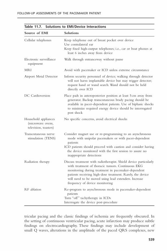
tricular pacing and the classic findings of ischemia are frequently obscured. Inthe setting of continuous ventricular pacing, acute infarction may produce subtlefindings on electrocardiography. These findings may include development ofsmall Q waves, alterations in the amplitude of the paced QRS complexes, new
FOLLOW-UP ASSESSMENTS OF THE PACEMAKER PATIENT
539
Table 11.7. Solutions to EMI/Device Interactions
Source of EMI Solutions
Cellular telephones Keep telephone out of breast pocket over deviceUse contralateral earKeep fixed high-output telephones; i.e., car or boat phones at
least 6 inches away from device
Electronic surveillance Walk through entranceway without pauseequipment
MRI Avoid with pacemaker or ICD unless extreme circumstance
Airport Metal Detector Inform security personnel of device; walking through detector will not harm implantable device but may trigger detector;request hand or wand search. Wand should not be held directly over ICD
DC Cardioversion Place pads in anteroposterior position at least 5 cm away fromgenerator. Backup transcutaneous brady pacing should be available in pacer-dependent patients. Use of biphasic shocks to minimize required energy device should be interrogated post shock
Household appliances No specific concerns, avoid electrical shocks(microwave ovens,television, toasters)
Transcutaneous nerve Consider magnet use or re-programming to an asynchronous stimulation (TENS) mode with unipolar pacemakers or with pacer-dependent
patientsICD patients should proceed with caution and consider having
the device monitored with the first session to assure no inappropriate detections
Radiation therapy Discuss treatment with radiotherapist. Shield device particularly with treatment of thoracic tumors. Continuous EKG monitoring during treatment in pacemaker-dependentpatients receiving high-dose treatment. Rarely, the devicewill need to be moved using lead extenders. Increasefrequency of device monitoring
RF ablation Re-program to asynchronous mode in pacemaker-dependent patients
Turn “off ” tachytherapy in ICDsInterrogate the device post-procedure
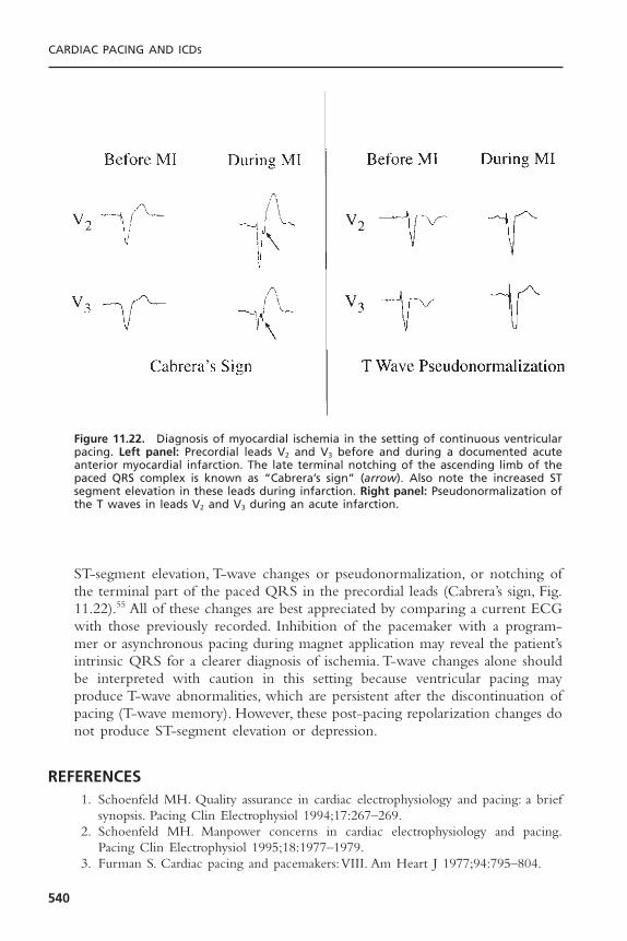
ST-segment elevation, T-wave changes or pseudonormalization, or notching ofthe terminal part of the paced QRS in the precordial leads (Cabrera’s sign, Fig.11.22).55 All of these changes are best appreciated by comparing a current ECGwith those previously recorded. Inhibition of the pacemaker with a program-mer or asynchronous pacing during magnet application may reveal the patient’sintrinsic QRS for a clearer diagnosis of ischemia. T-wave changes alone shouldbe interpreted with caution in this setting because ventricular pacing mayproduce T-wave abnormalities, which are persistent after the discontinuation ofpacing (T-wave memory). However, these post-pacing repolarization changes donot produce ST-segment elevation or depression.
REFERENCES1. Schoenfeld MH. Quality assurance in cardiac electrophysiology and pacing: a brief
synopsis. Pacing Clin Electrophysiol 1994;17:267–269.2. Schoenfeld MH. Manpower concerns in cardiac electrophysiology and pacing.
Pacing Clin Electrophysiol 1995;18:1977–1979.3. Furman S. Cardiac pacing and pacemakers:VIII. Am Heart J 1977;94:795–804.
CARDIAC PACING AND ICDS
540
Figure 11.22. Diagnosis of myocardial ischemia in the setting of continuous ventricularpacing. Left panel: Precordial leads V2 and V3 before and during a documented acuteanterior myocardial infarction. The late terminal notching of the ascending limb of thepaced QRS complex is known as “Cabrera’s sign” (arrow). Also note the increased STsegment elevation in these leads during infarction. Right panel: Pseudonormalization ofthe T waves in leads V2 and V3 during an acute infarction.

4. Griffin JC, Schuenenemyer TD, Hess KR, et al. Pacemaker follow up: its role in thedetection and correction of pacemaker system malfunction. Pacing Clin Electro-physiol 1986;9:387–391.
5. Furman S. Pacemaker follow-up. In: Furman S, Hayes DL, Holmes DR, eds. A Prac-tice of Cardiac Pacing. 2nd ed. Mount Kisco, NY: Futura, 1989.
6. Levine PA. Proceedings of the policy conference of the North American Society ofPacing and Electrophysiology on programmability and pacemaker follow-up pro-grams. Clin Prog Pacing Electrophysiol 1984;2:145–191.
7. DaCosta A, Kirkorian G, Cucherat M, et al. Antibiotic prophylaxis for permanentpacemaker implantation: a meta-analysis. Circulation 1998;97:1796–1801.
8. Schoenfeld MH. A primer on pacemaker programmers. Pacing Clin Electrophysiol1993;16:2044–2052.
9. MacGregor DC, Covvey HD, Noble EJ, et al. Computer-assisted reporting systemfor the follow-up of patients with cardiac pacemakers. Pacing Clin Electrophysiol1980;3:568–588.
10. Schoenfeld MH. Recommendations for implementation of a North American mul-ticenter arrhythmia device/lead database. Pacing Clin Electrophysiol 1992;15:1632–1636.
11. Byrd CL, Schwartz SJ, Gonzalez M, et al. Pacemaker clinic evaluations: key to earlyidentification of surgical problems. Pacing Clin Electrophysiol 1986;9:1259–1264.
12. Hoffman A, Jost M, Pfisterer M, et al. Persisting symptoms despite permanent pacing.Incidence, causes, and follow-up. Chest 1984;85:207–210.
13. Ausubel K, Furman S. The pacemaker syndrome. Ann Intern Med 1985;103:420–429.
14. Ellenbogen KA,Thames MD, Mohanty PK. New insights into pacemaker syndromegained from hemodynamic, humoral and vascular responses during ventriculoatrialpacing. Am J Cardiol 1990;65:53–59.
15. Kenny RS, Sutton R. Pacemaker syndrome. BMJ 1986;293:902–903.16. Deharo JC, Brunetto AB, Bellocci F, et al. DDDR pacing driven by contractility
versus DDI pacing in vasovagal syncope: a multi-center, randomized study. PacingClin Electrophysiol 2003;26:447–450.
17. Connolly SJ, Sheldon R, Thorpe KE, et al. Pacemaker therapy for prevention ofsyncope in patients with recurrent severe vasovagal syncope: Second VasovagalPacemkaer Study (VPS II): a randomized trial. JAMA 2003;289:2224–2229.
18. Michaud GF, Pelosi F Jr, Noble MD, et al. A randomized trial comparing heparininitiation 6h or 24h after pacemaker or defibrillator implantation. J Am Coll Cardiol2000;35:1915–1918.
19. Saliba BC, Ghantous AE, Schoenfeld MH, et al.Twiddler’s syndrome with transvenousdefibrillators in the pectoral region. Pacing Clin Electrophysiol 1999;22:1419–1421.
20. Steiner RM, Morse D. The radiology of cardiac pacemakers. JAMA 1978;240:2574–2576.
21. Morse D, Parsonnet V, Gessman L, et al. eds. A guide to cardiac pacemakers, defi-brillators, and related products. North Carolina: Droege Computing Services; 1991.
22. Mugica J, Henry L, Rollet M, et al. The clinical utility of pacemaker follow-upvisits. Pacing Clin Electrophysiol 1986;9:1249–1251.
23. Schoenfeld MH. Pacemaker programmers: an updated synopsis. Cardiac Electro-physiol Rev 1999;3:20–23.
24. Blitzer ML, Marieb MA, Schoenfeld MH. Inability to communicate with ICDs: anunderreported failure mode. Pacing Clin Electrophysiol 2001;24:13–15.
FOLLOW-UP ASSESSMENTS OF THE PACEMAKER PATIENT
541
25. Levine PA, Sholder J, Duncan JL. Clinical benefits of telemetered electrograms inassessment of DDD function. Pacing Clin Electrophysiol 1984;7:1170–1177.
26. Sanders R, Martin R, Fruman H, Goldberg MK. Data storage and retrieval byimplantable pacemakers for diagnostic purposes. Pacing Clin Electrophysiol 1984;7:1228–1233.
27. Sholder J, Levine PA, Mann BM, et al. Bidirectional telemetry and interrogation.In: Barold SS, Mugica J, eds. Cardiac pacing. The third decade of cardiac pacing.Mount Kisco, NY: Futura, 1982:145–166.
28. Duffin EG Jr. The marker channel: a telemetric diagnostic aid. Pacing Clin Elec-trophysiol 1984;7:1165–1169.
29. Strathmore NF, Mond HG. Noninvasive monitoring and testing of pacemaker func-tion. Pacing Clin Electrophysiol 1987;10:1359–1370.
30. Zinberg A. Transtelephonic follow-up. Clin Prog Pacing Electrophysiol 1984;2:177.31. Famularo MA, Kennedy HL. Ambulatory electrocardiography in the assessment of
pacemaker function. Am Heart J 1982;104:1086–1094.32. Danilovic D, Ohm OH. Pacing threshold trends and variability in modern tined
leads assessed using high resolution automatic measurements: conversion of pulsewidth into voltage thresholds. Pacing Clin Electrophysiol 1999;22:567–587.
33. Luceri RM, Hayes DL. Follow-up of DDD pacemakers. Pacing Clin Electrophys-iol 1984;7:1187–1194.
34. Schoenfeld MH, Markowitz HT. Device follow-up in the age of automaticity. PacingClin Electrophysiol 2000;23:803–806.
35. Wilkoff BL, Cook JR, Epstein AE, et al. Dual-chamber pacing or ventricular back-up pacing in patients with an implantable defibrillator: the Dual Chamber and VVIDefibrillator (DAVID) Trial. JAMA 2002;288:3115–3123.
36. Vardas PE, Simantrakis EN, Parthenakis FL, et al. AAIR versus DDDR pacing inpatients with impaired sinus node chronotropy: an echocardiographic and car-diopulmonary study. Pacing Clin Electrophysiol 1997;20:1762–1768.
37. Meluzin J, Novak M, Mullerov AJ, et al.A fast and simple echocardiographic methodof determination of the optimal atrioventricular delay in patients after biventricularstimulation. Pacing Clin Electrophysiol 2004;27:58–64.
38. Sogaard P, Egeblad H, Pedersen AK, et al. Sequential versus simultaneous biventric-ular resynchronization for severe heart failure. Circulation 2002;106:2078–2084.
39. Theuns DA, Res JC, Jordaens LJ. Home monitoring in ICD therapy: future per-spectives. Europace 2003;5:139–142.
40. Schoenfeld MH, Compton SJ, Mead RH, et al. Remote monitoring of implantablecardioverter-defibrillators: a prospective analysis. Pacing Clin Electrophysiol (inpress).
41. Barold SS, Schoenfeld MH. Pacemaker elective replacement indicators: latched orunlatched? Pacing Clin Electrophysiol 1989;12:990–995.
42. Barold SS, Schoenfeld MH, Falkoff MD, et al. Elective replacement indicators ofsimple and complex pacemakers. In: Barold SS, Mugica J, eds. New perspectives incardiac pacing. 2nd ed. Mount Kisco, NY: Futura, 1991:493–526.
43. Levine PA, Barold SS, Fletcher RD, Talbot P. Adverse acute and chronic effects ofelectrical defibrillation and cardioversion of implanted unipolar cardiac pacingsystems. J Am Coll Cardiol 1983;1:1413–1422.
44. Gimbel JR, Johnson D, Levine PA, et al. Safe performance of magnetic resonanceimaging on five patients with permanent cardiac pacemakers. Pacing Clin Electro-physiol 1996;19:913–919.
CARDIAC PACING AND ICDS
542

45. Sommer T,Vahlhaus C, Lauck G, et al. MR imaging and cardiac pacemakers: In vitroevaluation and in vivo studies in 51 patients at 0.5T. Radiology 2000;215:869–879.
46. Cooper D, Wilkoff B, Masterson M, et al. Effects of extracorporeal shock wavelithotripsy on cardiac pacemakers and its safety in patients with implanted cardiacpacemakers. Pacing Clin Electrophysiol 1988;11:1607–1616.
47. Pinski SL, Trohman RG. Interference in implanted cardiac devices, Part 1. PacingClin Electrophysiol 2002;25:1367–1381.
48. Hayes DL, Wang PJ, Reynolds DW, et al. Interference with cardiac pacemakers bycellular telephones. N Engl J Med 1997;336:1473–1479.
49. Blitzer ML, Schoenfeld MH. Effects of electromagnetic interference on implantedcardiac devices. In: Raviele A, ed. Cardiac arrhythmias 2003. Milan: Springer-VerlagItalia 2004:911–918.
50. Groh WJ, Boschee SA, Engelstein ED, et al. Interactions between electronic articlesurveillance systems and implantable cardioverter-defibrillators. Circulation 1999;100:387–392.
51. McIvor ME, Reddinger J, Floden E, Sheppard RC. Study of pacemaker andimplantable cardioverter defibrillator triggering by electronic article surveillancedevices (SPICED TEAS). Pacing Clin Electrophysiol 1998;221:1847–1861.
52. Goldschlager N, Epstein A, Friedman P, et al. Environmental and drug effects onpatients with pacemakers and implantable cardioverter defibrillators. Arch InternMed 2001;161:649–655.
53. Eriksson M, Schuller H, Sjolund B. Hazards from transcutaneous nerve stimulationin patients with pacemakers. Lancet 1978;1:1319.
54. Philbin DM, Marieb MA, Aithal KH, Schoenfeld MH. Inappropriate shocks deliv-ered by an ICD as a result of sensed potentials from a transcutaneous electronicnerve stimulation unit. Pacing Clin Electrophysiol 1998;21:2010–2011.
55. Barold SS, Falkoff MD, Ong LS, et al. Electrocardiographic diagnoses of myocardialinfarction during ventricular pacing. Cardiol Clin 1987;5:403.
FOLLOW-UP ASSESSMENTS OF THE PACEMAKER PATIENT
543

AAAIR pacing, 156Ablation techniques, radiofrequency catheter,
42. See also Radiofrequency ablationAccelerometers, 108, 109f
advantage of, 112body motion detected by, 111in rate-adaptive pacing systems, 109–110,
109fAccufix J lead, 248Accufix wire fragment retrieval, for lead
extraction, 257, 257fActivity sensors
compared with accelerometers, 111–112limitations of, 110–111and minute-ventilation sensing, 114in rate-adaptive systems, 109
Adolescents, pacing for, 27–29Advanced life support, in pacemaker clinic,
501AEI
defined, 266bin ventricular-based timing system, 292,
294, 295fAfterdepolarizations, 77–78Air embolism
avoidance of, 234bas implantation complication, 234
Alkalosis, ventricular capture in, 178American College of Cardiology (ACC)
guidelines of, 201, 259pacemaker criteria of, 4pacing codes introduced by, 266
American Heart Association (AHA)guidelines of, 201, 259pacemaker criteria of, 4pacing codes introduced by, 266on temporary pacing, 40
Amplitude of pacing stimulation, malfunctionof, 331
Analgesia, for elective generator replacement.See also Pain
Anatomyin cardiac pacing, 2–3, 2tcoronary venous, 426, 426f–428f
Anesthesia, for implantation procedures, 198,215
Angina, in follow-up assessment, 506Angioplasty, temporary pacing during, 41Antiarrhythmics
and pacemaker malfunction, 330and stimulation threshold, 61and ventricular thresholds, 178
Antibiotic prophylaxis, for pacemakerimplantation, 205
Antibiotic therapy, recurrence of sepsis after,245
Anticoagulationin cardiac perforation, 236and pacemaker implantation, 204–205
Antitachycardia pacing (ATP), 400, 401fburst and ramp, 401compared with low-energy cardioversion,
400, 402frisk of, 479
Antitachycardia therapies, 536
Index
545
INDEX
546
Arrhythmias. See also specific arrhythmiasdetected by ICDs, 397–399, 399fas lead placement complication, 234–235,
235bArtifacts, recording, 337f, 338f, 350, 356–358Aspiration, with transesophageal pacing,
187ATP interval, in ICD programming, 474tAtrial antitachycardia (AAI) pacemakers, 73Atrial-based pacing, compared with
ventricular pacing, 157–158Atrial capture threshold test, 316IfAtrial fibrillation
alternating with bradycardia, 16fand inappropriate ICD therapy, 487f,
488f–489fintermittent ventricular tracking of, 528fmorphology score for, 477fprevention algorithm in, 305
Atrial flutterelectrograms during, 397fintermittent ventricular tracking of, 528ftemporary pacing for, 42
Atrial flutter response (AFR), 304–305, 306fAtrial lead implantation, 221–223Atrial-only defibrillators, 407Atrial pacing
appropriate, 521fhemodynamic evaluation of, 139tsynchronous (AOO), 268
Atrial refractory period (ARP), 281Atrial sensing window (ASW), 277Atrial synchronous (P-tracking) pacing,
277–278, 279fAtrioventricular (AV) block
acquired, 5differential diagnosis of, 10, 11bECGs in, 5f, 6f, 8f, 9fescape rhythm in, 5, 6f, 10indications for permanent pacing in,
7–10, 8f, 9f, 10fAV sequential vs. VVI pacing for, 33t–34tcommon medications causing, 17bECG in, 37fhigh-grade
during acute MI, 39causes of, 11bescape rhythm in, 6f
programming for, 56
strength-duration relation in, 51ftemporary pacing for, 36
Atrioventricular (AV) conduction, and modeselection, 155, 155f, 156
Atrioventricular (AV) delays, and optimalhemodynamics, 136
Atrioventricular (AV) interval, 283–289,283f–285f, 287f, 288f
appropriate programming of, 524–526atrial sensed vs. atrial paced, 137, 138f, 139differential, 286–288, 287fDoppler studies for, 137, 137f, 138feffects of, 136–137hemodynamics of short, 421, 421fhysteresis, 288–289and left ventricular performance, 422, 422frate-adaptive, 288, 288f
Atrioventricular (AV) junction, ablation of,423
Atrioventricular (AV) nodeanatomy of, 1, 2tphysiology of, 3–4
Atrioventricular (AV) pacingatrial vs., 139–140, 139themodynamic evaluation of, 124, 125t, 139tsequential, 178
Atrioventricular (AV) sequential asynchronous(DOO) pacing, 268, 269f
Atrioventricular (AV) synchronous pacing,ventricular pacing compared with, 136
Atrioventricular (AV) synchronyadvantages of, 123–136, 135–136and atrial pressures, 130–135, 130f–135fbenefits of, 126, 127fblood pressure in, 123–126, 123f–125fand cardiac output, 126–129hemodynamics of, 122–123in higher heart rates, 153and mode selection, 155, 157and pacemaker syndrome, 140and rate modulation, 153, 154f, 155and stroke volume, 151
Atrioventricular optimization, 421, 422fAtrioventricular sequential, non-P-
synchronous pacingwith dual-chamber sensing, 276, 277f,
278frate-modulated with dual-chamber sensing,
276–277
INDEX
547
Atrioventricular sequential, ventricularinhibited (DV), 273, 274f
Atropine, in bradycardia, 36, 37Automated capture features, 79–82, 80fAutomaticity, in follow-up assessment, 524Automatic sensing alogorithm, 341Autosensing functions, 82AVID study, 381A waves
absense of, 419fgiant, 133, 135in PCW pressures, 132–133
Axillary vein, thrombosis of, 239Axillary vein approach, to pacemaker
implantation, 211–212f, 213
BBack pain, with transesophageal pacing, 186Bacteremia, in temporary pacing, 183Bacterial endocarditis, temporary pacing in,
41–42Bandpass filtering, signal processing with,
104–105, 105fBase rate behavior
atrial-based timing in, 295–296, 296fatrial fibrillation prevention algorithms in,
305atrial flutter response, 304–305, 306fautomatic mode switch, 298and battery status, 533tcomparison of atrial-based and ventricular-
based systems, 296–298, 297fmode switching, 302–304, 303f, 305frate smoothing, 306sensor input, 298and sinus preference, 305upper rate, 298–302, 299f, 300fventricular-based timing, 292–294, 295fventricular rate regularization, 306
Batteriesdecay characteristics of, 101, 101fdepletion of, 467and elective replacement indicators, 469lithium-iodine, 98, 99–102, 99flongevity of, 100–101and pacemaker behavior, 533t
Beta blockersand ICD therapy, 383and stimulation threshold, 61
Bifascicular blockin asymptomatic patients, 10–11indications for pacing in, 10–14
Bipolar leadsinsulation defects in, 331in minute-ventilation pacemakers, 115
Bipolar pacingadvantages of, 65stimulation threshold in, 58–59
Bipolar split cathodal configuration, 65, 66fBipolar systems, pacing stimulus in, 325,
326fBiventricular device implants, 157Biventricular pacing, 65–67
in advanced heart failure, 25complications of, 245in HOCM, 147and intrinsic conduction delay, 432, 434f12 lead ECGs of, 449flong-term benefits from, 149with loss of capture, 363polarities for, 434, 435fpulse generator configurations for, 434,
436fand ventricular hemodynamics, 148f
Biventricular pacing systemsdiaphragmatic stimulation in, 511growth in, 408
Blanking period, 106, 281Bleeding
as implantation complication, 243during pacemaker implantation, 234
Blood pressureand AV synchrony, 123–126, 123f–125fin follow-up clinic, 507as function of pacing mode, 511
Bradyarrhythmiaspercussion pacing for, 188temporary pacing for, 163
Bradyasystolic arrest, 189Bradycardia
in children, 27–28in sinus node dysfunction, 15temporary pacing for, 36
Bradycardia pacing, 402fby ICD, 483problems with, 482fand syncope, 495–496
“Buddy” wire, 256
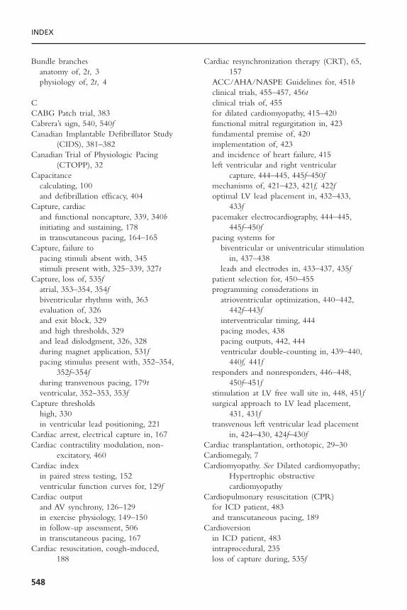
INDEX
548
Bundle branchesanatomy of, 2t, 3physiology of, 2t, 4
CCABG Patch trial, 383Cabrera’s sign, 540, 540fCanadian Implantable Defibrillator Study
(CIDS), 381–382Canadian Trial of Physiologic Pacing
(CTOPP), 32Capacitance
calculating, 100and defibrillation efficacy, 404
Capture, cardiacand functional noncapture, 339, 340binitiating and sustaining, 178in transcutaneous pacing, 164–165
Capture, failure topacing stimuli absent with, 345stimuli present with, 325–339, 327t
Capture, loss of, 535fatrial, 353–354, 354fbiventricular rhythms with, 363evaluation of, 326and exit block, 329and high thresholds, 329and lead dislodgment, 326, 328during magnet application, 531fpacing stimulus present with, 352–354,
352f–354fduring transvenous pacing, 179tventricular, 352–353, 353f
Capture thresholdshigh, 330in ventricular lead positioning, 221
Cardiac arrest, electrical capture in, 167Cardiac contractility modulation, non-
excitatory, 460Cardiac index
in paired stress testing, 152ventricular function curves for, 129f
Cardiac outputand AV synchrony, 126–129in exercise physiology, 149–150in follow-up assessment, 506in transcutaneous pacing, 167
Cardiac resuscitation, cough-induced,188
Cardiac resynchronization therapy (CRT), 65,157
ACC/AHA/NASPE Guidelines for, 451bclinical trials, 455–457, 456tclinical trials of, 455for dilated cardiomyopathy, 415–420functional mitral regurgitation in, 423fundamental premise of, 420implementation of, 423and incidence of heart failure, 415left ventricular and right ventricular
capture, 444–445, 445f–450fmechanisms of, 421–423, 421f, 422foptimal LV lead placement in, 432–433,
433fpacemaker electrocardiography, 444–445,
445f–450fpacing systems for
biventricular or univentricular stimulationin, 437–438
leads and electrodes in, 433–437, 435fpatient selection for, 450–455programming considerations in
atrioventricular optimization, 440–442,442f–443f
interventricular timing, 444pacing modes, 438pacing outputs, 442, 444ventricular double-counting in, 439–440,
440f, 441fresponders and nonresponders, 446–448,
450f–451fstimulation at LV free wall site in, 448, 451fsurgical approach to LV lead placement,
431, 431ftransvenous left ventricular lead placement
in, 424–430, 424f–430fCardiac transplantation, orthotopic, 29–30Cardiomegaly, 7Cardiomyopathy. See Dilated cardiomyopathy;
Hypertrophic obstructivecardiomyopathy
Cardiopulmonary resuscitation (CPR)for ICD patient, 483and transcutaneous pacing, 189
Cardioversionin ICD patient, 483intraprocedural, 235loss of capture during, 535f
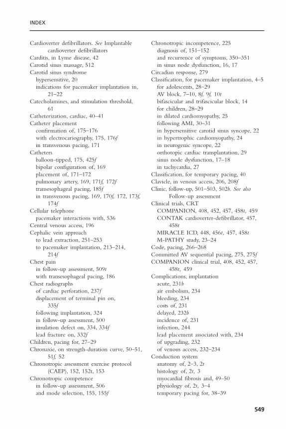
INDEX
549
Cardioverter defibrillators. See Implantablecardioverter defibrillators
Carditis, in Lyme disease, 42Carotid sinus massage, 512Carotid sinus syndrome
hypersensitive, 20indications for pacemaker implantation in,
21–22Catecholamines, and stimulation threshold,
61Catheterization, cardiac, 40–41Catheter placement
confirmation of, 175–176with electrocariography, 175, 176fin transvenous pacing, 171
Cathetersballoon-tipped, 175, 425fbipolar configuration of, 169placement of, 171–172pulmonary artery, 169, 171f, 172ftransesophageal pacing, 185fin transvenous pacing, 169, 170f, 172, 173f,
174fCellular telephone
pacemaker interactions with, 536Central venous access, 196Cephalic vein approach
to lead extraction, 251–253to pacemaker implantation, 213–214,
214fChest pain
in follow-up assessment, 509twith transesophageal pacing, 186
Chest radiographsof cardiac perforation, 237fdisplacement of terminal pin on,
335ffollowing implantation, 324in follow-up assessment, 500insulation defect on, 334, 334flead fracture on, 332f
Children, pacing for, 27–29Chronaxie, on strength-duration curve, 50–51,
51f, 52Chronotropic assessment exercise protocol
(CAEP), 152, 152t, 153Chronotropic competence
in follow-up assessment, 506and mode selection, 155, 155f
Chronotropic incompetence, 225diagnosis of, 151–152and recurrence of symptoms, 350–351in sinus node dysfunction, 16, 17
Circadian response, 279Classification, for pacemaker implantation, 4–5
for adolescents, 28–29AV block, 7–10, 8f, 9f, 10tbifascicular and trifascicular block, 14for children, 28–29in dilated cardiomyopathy, 25following AMI, 30–31in hypersensitive carotid sinus syncope, 22in hypertrophic cardiomyopathy, 24in neurogenic syncope, 22orthotopic cardiac transplantation, 29sinus node dysfunction, 17–18in tachycardia, 27
Classification, for temporary pacing, 40Clavicle, in venous access, 206, 208fClinic, follow-up, 501–503, 502b. See also
Follow-up assessmentClinical trials, CRT
COMPANION, 408, 452, 457, 458t, 459CONTAK cardioverter-defibrillator, 457,
458tMIRACLE ICD, 448, 456t, 457, 458tM-PATHY study, 23–24
Code, pacing, 266–268Committed AV sequential pacing, 275, 275fCOMPANION clinical trial, 408, 452, 457,
458t, 459Complications, implantation
acute, 231bair embolism, 234bleeding, 234costs of, 231delayed, 232bincidence of, 231infection, 244lead placement associated with, 234of upgrading, 232of venous access, 232–234
Conduction systemanatomy of, 2–3, 2thistology of, 2t, 3myocardial fibrosis and, 49–50physiology of, 2t, 3–4temporary pacing for, 38–39
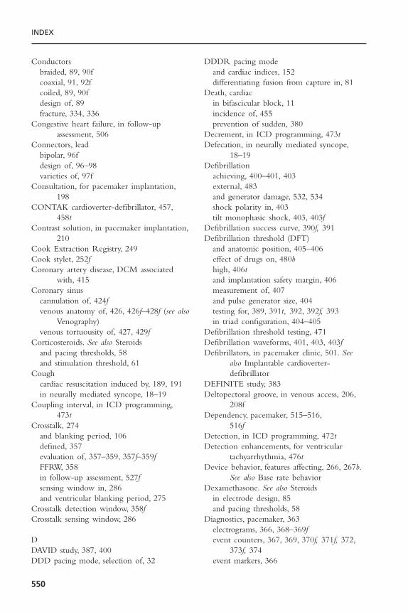
INDEX
550
Conductorsbraided, 89, 90fcoaxial, 91, 92fcoiled, 89, 90fdesign of, 89fracture, 334, 336
Congestive heart failure, in follow-upassessment, 506
Connectors, leadbipolar, 96fdesign of, 96–98varieties of, 97f
Consultation, for pacemaker implantation,198
CONTAK cardioverter-defibrillator, 457,458t
Contrast solution, in pacemaker implantation,210
Cook Extraction Registry, 249Cook stylet, 252fCoronary artery disease, DCM associated
with, 415Coronary sinus
cannulation of, 424fvenous anatomy of, 426, 426f–428f (see also
Venography)venous tortuousity of, 427, 429f
Corticosteroids. See also Steroidsand pacing thresholds, 58and stimulation threshold, 61
Coughcardiac resuscitation induced by, 189, 191in neurally mediated syncope, 18–19
Coupling interval, in ICD programming,473t
Crosstalk, 274and blanking period, 106defined, 357evaluation of, 357–359, 357f–359fFFRW, 358in follow-up assessment, 527fsensing window in, 286and ventricular blanking period, 275
Crosstalk detection window, 358fCrosstalk sensing window, 286
DDAVID study, 387, 400DDD pacing mode, selection of, 32
DDDR pacing modeand cardiac indices, 152differentiating fusion from capture in, 81
Death, cardiacin bifascicular block, 11incidence of, 455prevention of sudden, 380
Decrement, in ICD programming, 473tDefecation, in neurally mediated syncope,
18–19Defibrillation
achieving, 400–401, 403external, 483and generator damage, 532, 534shock polarity in, 403tilt monophasic shock, 403, 403f
Defibrillation success curve, 390f, 391Defibrillation threshold (DFT)
and anatomic position, 405–406effect of drugs on, 480bhigh, 406tand implantation safety margin, 406measurement of, 407and pulse generator size, 404testing for, 389, 391t, 392, 392f, 393in triad configuration, 404–405
Defibrillation threshold testing, 471Defibrillation waveforms, 401, 403, 403fDefibrillators, in pacemaker clinic, 501. See
also Implantable cardioverter-defibrillator
DEFINITE study, 383Deltopectoral groove, in venous access, 206,
208fDependency, pacemaker, 515–516,
516fDetection, in ICD programming, 472tDetection enhancements, for ventricular
tachyarrhythmia, 476tDevice behavior, features affecting, 266, 267b.
See also Base rate behaviorDexamethasone. See also Steroids
in electrode design, 85and pacing thresholds, 58
Diagnostics, pacemaker, 363electrograms, 366, 368–369fevent counters, 367, 369, 370f, 371f, 372,
373f, 374event markers, 366

INDEX
551
measured data, 364, 366stored data, 367
Diaphragmatic stimulationin follow-up assessment, 508on physical examination, 511
Diathermy, electrical interference from, 72Digital sampling, and recording artifacts, 336,
338fDilated cardiomyopathy, 24–25
abnormal electrical timing in, 415–420and AV sequential pacing, 178biventricular pacemaking in, 196heart failure associated with, 415indications for pacing in, 25
Dilator, in pacemaker implantation, 210Dilator-sheath technique, 209DINAMIT study, 383Discharges, ICD
isolated, 484, 486, 487fmultiple appropriate, 486, 495, 496fmultiple inappropriate, 486–492, 487f–492f,
496, 496fDislodgment
in follow-up visit, 503in transvenous pacing, 179
Documentationof implant procedure, 323importance of, 258–259
Doppler analysisfor AV interval, 136, 137f, 138ffor CRT patients, 453in CRT programming, 440mitral inflow patterns, 417, 418ftransmitral blood flow, 441, 442f, 443f
Double countingdue to loss of atrial tracking, 439, 440fexample of, 489, 490fprevention of ventricular, 440, 441f
“Double tachycardia,” 492Driving restrictions, in ICD follow-up, 467Drugs. See also Medications; specific drugs
defibrillation threshold elevated by, 480btoxicity, 8transient bradycardia caused by, 17b, 42
Dual Chamber and VVI ImplantableDefibrillator (DAVID), 143. See alsoDAVID study
Dual-chamber ICD systems, evolution of,386–387, 387f, 398–400
Dual-chamber pacemakers, 143AP chest radiograph of, 207fpreservation of AV synchrony using, 156
Dual-chamber pacingacute hemodynamic effects of, 23, 23fadvantages to, 31–32afterdepolarizations in, 78hemodynamic benefit of, 24potential adverse effects of, 400rate-modulated, 142–143and sensing with inhibition and tracking,
278–279, 280f, 281with single lead, 74vs. backup pacing, 143
Dual-chamber pacing systemscorrect lead connection in, 242discrimination enhancement features in,
478fand pacemaker syndrome, 141revision of, 226fventricular lead positioning in, 217–221
Dual-chamber rate-modulated (DDDR)pacing
risks of, 156and timing cycles, 307–313, 307f–312f
Dual-chamber systemsevaluation of crosstalk in, 357–359,
357f–359fin follow-up assessments, 527–529malfunction evaluation of
classes of, 351–352with sensing problems, 355–357stimulus present with loss of capture,
352–354, 352f–354fmyopotential triggering of ventricular
pacing in, 511pacemaker-mediated tachycardias in,
359–363, 361f, 362fDyspnea, in follow-up assessment, 507, 507f,
509t
EEchocardiogram, in cardiac perforation, 237fEdema, in follow-up assessment, 509t, 511Ejection fraction
and AV synchrony, 125t, 135in biventricular pacing, 149
Elective replacement indicators (ERIs), 469,531

INDEX
552
Electrical cycle, events of cardiac, 417fElectrical timing. See Disordered electrical
timingElectrocardiogram (ECG)
after pacemaker implantation, 229from DDDR pacemaker, 308fduring lead placement, 235paced, 265during pacemaker implantation, 200perforated pacing catheter on, 182f
Electrocardiographic guidance, for catheterplacement, 175, 176f
Electrocardiography, CRT, 444–445,445f–450f
Electrocauterycomplications with, 242effect on ICD of, 481and generator damage, 532, 534interference from, 72in lead extraction, 251
Electrode-myocardial interfaceinflammatory reaction at, 344injury at, 329
Electrodesactive fixation leads for, 86–89, 87f, 88fcapacitance of, 67chemical composition of, 84in CRT pacing systems, 433–437, 435fdesign of, 83epimyocardial, 95fixation mechanism of, 86, 87fmicrodislodgement of, 62–63orthogonal, 74permanent transvenous pacing, 87fand QRS morphology, 177, 177tshape of, 83steroid-eluting, 84–86, 85fsurface structure of, 83–84in transesophageal pacing, 186
Electrogram (EGM)after implantation, 324atrial, 488fbipolar atrial, 368f–369diagnostics with, 366–367far-field R wave on cardiac, 73, 73f, 74lead dislodgment on, 328low amplitude, 342tstored, 396–397, 397f, 398ftransesophageal cardiac, 186, 187f
unipolar, 175, 176f, 177ventricular, 488f
Electrogram (EGM), intracardiacbipolar, 72characteristics of, 69–71high-pass filtering of, 70intrinsic deflection in, 69, 70ftelemetry of, 107time-related changes in, 78
Electrogram morphology (EGM), 477fElectromagnetic interference (EMI),
345device interactions with, 539teffect on ICD, 481ICD therapy triggered by external,
491–492sources of, 534–535susceptibility to, 244
Emergenciesequipment for, 200single-chamber pacing in, 177–178transcutaneous pacing in, 164transvenous pacing in, 175, 189
Emphysema, and transcutaneous pacingthresholds, 165–166
End-diastolic volume index (EDVI), 129fEndless-loop tachycardia (ELT), 314–317, 360,
361fin atrial capture threshold test, 316, 316fautomatic termination of, 360, 362fin biventricular pacing, 361
Endocardial activation maps, electroanatomic,453f
Endocarditispacemaker associated, 244–245temporary pacing in, 41–42
Epicardial pacing, 183, 184fEpicardium, pacing leads sutured to, 95, 95fEpinephrine, and ventricular thresholds, 178Erb’s dystrophy, 7, 8Erosion
of generator, 509pacemaker, 510fof pacing hardware, 242–243, 243f
Escape rhythm, after mitral valve replacement,516f
Esophageal lead, 354Evaluation, outpatient pacemaker, 324. See also
Follow-up assessment

INDEX
553
Event counterssubsystem performance, 369, 371f, 372ftime-based system performance, 369, 372,
373, 373ftotal system performance, 367, 369, 370f
Event logs, in device interrogation, 469,470f
Event markers, function of, 366Event rercords, histograms of, 519, 519fExcitability, property of, 47Excitable tissues, characteristics of, 48Exercise
accelerometers during, 111–112and QT interval, 115and rate-adaptive pacing systems, 110–111rate adaptive response to, 114as work, 150
Exercise intolerance, in follow-up assessment,509t
Exercise physiology, and rate modulation,149–151, 150f
Exercise test, in sinus node dysfunction, 16Exercise tolerance
in follow-up assessment, 506in sinus node dysfunction, 15, 16–17
Exertional intolerance, 151Exit block, 61, 61f, 329Extracardiac signals, inappropriately sensed,
491, 491f–493fExtraction Registry, 249
FFaradic resistance, 69Far-field R wave (FFRW), 358, 491fFatigue, in sinus node dysfunction, 15, 16Femoral approach, to lead extraction,
253–257, 258f–259fFibrosis, myocardial, 49Fibrous capsule
development of, 56–57surrounding electrode, 56, 57f
Fibrous tissue, and lead maturation, 329Fick principle, 150Fixation technologies
active, 86–89, 87f, 88fin CRT, 425passive, 86
Flecainide, and stimulation threshold, 61Fluoropolymers, as lead insulators, 386
Fluoroscopydigital capabilities for, 199during generator insertion, 225in lead extraction, 250, 252in lead implantation, 217in pacemaker implantation, 211, 212f, 213in patient follow-up, 501, 502brequirements for, 197in transvenous pacing, 171–172, 173f, 174fventricular lead extraction with, 255f
Follow-up after ICD placementdevice interrogation, 468–469history in, 468immediate, 467physical examination in, 468procedures during, 481–483programming and, 471–480, 472t–474tsystem component testing, 469–480
Follow-up assessmentatrioventricular interval in, 524, 525common symptoms in, 509tdual-chamber systems in, 527–529elective replacement indicators in, 531–532,
531felectrocardiography in, 513–515immediate postimplantation period,
500–501outpatient monitoring in, 529–530, 530fpacemaker dependence in, 515–516,
516fphysical examination in, 508–509, 511–512programmers in, 517radiography in, 512, 513fsensing threshold determination in,
520–524, 521f, 522ftelemetry in, 517–520, 518f–520f
Framingham study, 415
GGenerator/defibrillator, transcutaneous pacing,
163, 164fGenerators. See also Pulse generators
compatibility with leads of, 227, 229tcomplications associated with, 231besophageal pacing, 185implantation of, 214–215indications for changing, 227insertion of, 225–229magnet-related pacing rate of, 102

INDEX
554
miniaturization of, 196problems with, 241–244, 242fradiographic identification of, 513fregistration of, 230temporary external transvenous pacing, 172ftemporary pacing, 169transcutaneous pacing, 163, 164ftransesophageal pacing, 185–186, 185f
Glucocorticoids, and ventricular thresholds,178
Glucose, and ventricular thresholds, 178Guidewires, 424f
HHeart block
and pacemaker dependence, 516ffrisk score for, 39transcutaneous pacing during, 166f
Heart block, congenitalpacing for, 27–29permanent pacing in, 28
Heart failureabnormal electrical timing in, 415–420cardiac contractility modulation for, 460early detection of, 408incidence of, 415indications for pacing in, 25and right ventricular pacing, 142–143,
158Heart rate
in exercise physiology, 150, 151histogram, 290fand minute ventilation, 114and response to exercise, 154fand treadmill testing, 114and VA conduction, 507f
Heart transplantation. See Cardiactransplantation
Hematomaas implantation complication, 243pocket, 503, 508
Hemodynamicsof alternative site right ventricular pacing,
141–142of atrioventricular synchrony, 122–1434in hypertrophic obstructive cardiomyopathy,
144–149Hemothorax, as implantation complication,
233
Heparin, low-molecular-weight, 204. See alsoAnticoagulation
His bundleanatomy of, 1, 2t, 3physiology of, 2t, 3–4recordings
in AV block, 13fin chronic bifascicular block, 12, 12f
Histogramsof event records, 519, 519fheart rate, 290f
Holter monitorinhibition of pacing on, 522, 522finsulation defect on, 332–333loss of ventricular capture on, 530fWenckebach phenomenon on, 506f
Hormonal levels, and ventricular pacing,136
Hydration, for pacemaker implantation,204
Hyperglycemiastimulation threshold during, 60ventricular capture in, 178
Hyperkalemiaand pacemaker malfunction, 330stimulation threshold during, 60and ventricular thresholds, 178
Hypertensive heart disease, and AV sequentialpacing, 178. See also Blood pressure
Hypertrophic cardiomyopathy, 128, 129and AV sequential pacing, 178indications for pacing in, 22–23obstructive (HOCM)
dual-chamber pacing in, 144–145impact of AV sequential pacing on, 145,
146f–147fpermanent pacing for, 24
Hypotensionrationale for pacing in, 126in ventricular pacing, 126
Hypoxemia, stimulation threshold during, 60Hypoxia
in sleep apnnea, 8ventricular capture in, 178
Hysteresispauses associated with, 350programming of, 289–292, 290f, 291frefinement of search, 289, 292types of, 289

INDEX
555
IImpedance
calculating, 66–67defined, 62determination of, 62evolution of, 63high atrial lead, 518fmeasurement-to-measurement changes in,
330in minute-ventilation sensing, 113, 113f,
114polarization, 63, 64f, 79sensing, 78–79tripolar transthoracic, 113, 113f, 114
Implantable cardioverter-defibrillators (ICDs)arrhythmia detection of, 397–399, 399fatrial defibrillators, 407clinical trials with, 481–484evolution of, 380indications for, 380–384, 381bintra-operative management of, 532, 534,
534tlead systems for, 385 (see also Lead design)longevity of, 409primary function of, 408pulse generators for, 384 (see also Pulse
generators)rate sensing in, 394–397, 394f–395f, 397fremote monitoring of, 409stored electrograms in, 396–397, 397f, 398f
Implantable cardioverter-defibrillator (ICD)therapies, 143
arrhythmia discrimination in, 408defibrillation, 400, 401, 403–407evolution of, 409pacing, 398–400
Implantation, ICD, 387. See also Follow-updefibrillation testing in, 388–389, 390f–391ffollow-up after, 393principles of, 387–388venous access for, 388
Implantation, pacemaker, 196approaches to
axillary vein, 211–212f, 213cephalic vein, 213–214, 214fsubclavian, 209
causes of arrhythmia during, 235bcomplications of, 231–249cost-effectiveness of, 202
decision process for, 203fdocumentation of, 323–324ECG during, 200epicardial and transmyocardial lead
placement in, 223–224generator insertion, 225–229inflammatory response to, 57, 57flead insertion in, 215–217
atrial implantation, 221–223ventricular positioning, 217–221
logistical requirements for, 198–200medical-legal aspects of, 258–259, 259bpacemaker pocket in, 214–215patient assessment for, 200–202, 203fpatient preparation for, 205–206physician qualifications for, 197–198post-procedure management of, 229–230preimplantation orders, 204–205procedure for, 206–214single-lead VDD pacing, 224–225sites for, 205, 206, 208f, 483surface landmarks for, 208fteam approach to, 197
Infectionas complication, 244–245in temporary pacing, 183
Inflammatory response, to pacemakerimplantation, 57, 57f
Informed consent, 201, 202Insulation
failure, 342tlead
defects in, 330–334, 341, 344evolution of, 386for permanent pacing, 91
polyurethane, 93, 93t, 94, 94fsilicone rubber, 91, 93t
Internet, and patient monitoring systems, 530Interrogation, device
event logs, 469, 470fprogrammed parameters for, 468–469system data in, 469
Interventricular delaydefined, 418in dilated cardiomyopathy, 416–419
Interventricular refractory period (IVRP), 77Intravascular hemodynamic monitors, 408Intraventricular conduction disorders,
temporary pacing for, 38–40

INDEX
556
Intraventricular delay, 419–420Isoproterenol
and stimulation threshold, 61in torsades de pointes, 43and ventricular thresholds, 178
JJ retention wire, 89, 199J-shaped active-fixation lead, 222, 222f
KKearns-Sayre syndrome, 7, 8
LLaboratory tests, pre-implant, 204Lead conductor fractures, 512Lead design, 82
conductors in, 89–91connectors in, 96electrodes, 83–89insulation in, 91–94
Lead-extraction kit, 250Lead placement
complications associated with, 231b,234–244
dislodgment rates and, 238–239indications for replacement, 348tleft ventricular
optimal, 432–433, 433fsurgical approach to, 431, 431ftransvenous approach to, 424–425, 424f,
425fparameters for, 221t, 223transvenous left ventricular, 425f, 426–430,
426f–430fLeads. See also Atrial lead implantation;
Ventricular lead positioningabandonment of, 258characteristics of, 216bcoaxial, 336compatibility with generators of, 227, 229tcomponents of, 82in CRT pacing systems, 433–437, 435fdiscontinued styles, 227dislodgment of, 326, 328, 342t
atrial, 222fincidence of, 231and undersensing, 344
epicardial placement, 223
epimyocardial, 95, 95fextraction of
Accufix wire fragment retrieval, 257, 257fcephalic approach, 251complications of, 247coronary venous leads, 258documentation for, 258–259femoral approach to, 253–257, 258f–259findications for, 246b, 247–249information for, 250bprinciples of, 245–247risk of death from, 249technique for, 249–251, 254fthoracotomy for, 258tools for, 251–258, 252f, 254f
failure of, 248, 512fracture of, 89, 238, 493f
diagnosis of, 332fin follow-up assessment, 518f
implantation of, 215–217registration of, 230transmyocardial placement, 223, 224f
Lead systemsevolution of, 385insulation for, 386triad configuration for, 404types of, 385f, 386unipolar configuration for, 404
Left bundle branch blockbiventricular sensing in, 439, 439fcomplete, 10
Left ventricledysfunction, 7filling velocities for, 418fand prolonged native AV conduction, 416,
419fpumping function of, 423
Left ventricular pacinghemodynamics of, 145–149and intrinsic conduction delay, 432, 434f
Left ventricular stimulation thresholds, high,427–430, 429f, 430f
Left ventricular systolic dysfunction, 24–25.See also Cardiomyopathy, dilated
Left ventricular systolic pressure, intranscutaneous pacing, 167
Lithium-iodine batteries, 98, 99–102, 99fadvantage of, 99–100decay characteristics of, 101, 101f
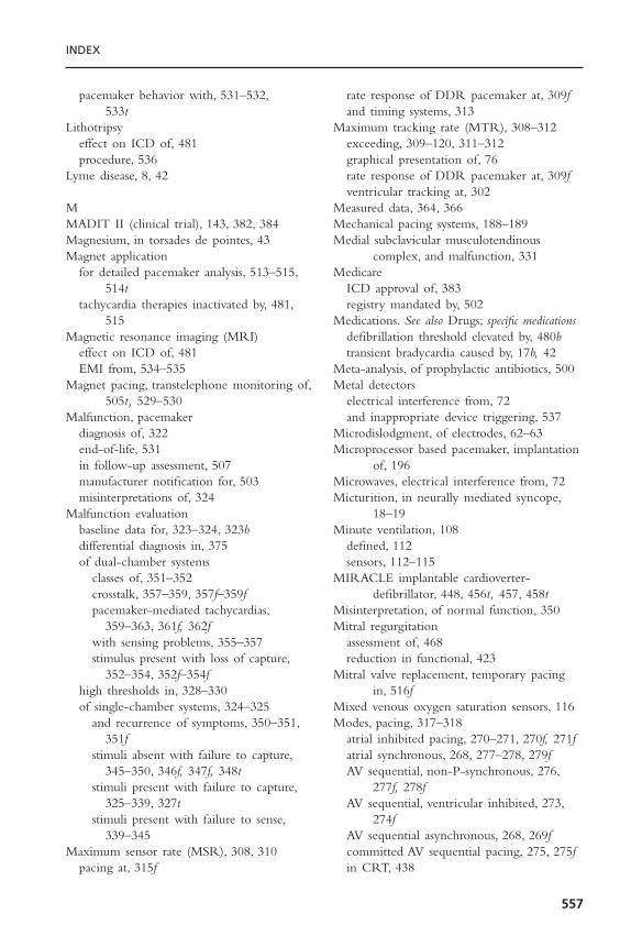
INDEX
557
pacemaker behavior with, 531–532,533t
Lithotripsyeffect on ICD of, 481procedure, 536
Lyme disease, 8, 42
MMADIT II (clinical trial), 143, 382, 384Magnesium, in torsades de pointes, 43Magnet application
for detailed pacemaker analysis, 513–515,514t
tachycardia therapies inactivated by, 481,515
Magnetic resonance imaging (MRI)effect on ICD of, 481EMI from, 534–535
Magnet pacing, transtelephone monitoring of,505t, 529–530
Malfunction, pacemakerdiagnosis of, 322end-of-life, 531in follow-up assessment, 507manufacturer notification for, 503misinterpretations of, 324
Malfunction evaluationbaseline data for, 323–324, 323bdifferential diagnosis in, 375of dual-chamber systems
classes of, 351–352crosstalk, 357–359, 357f–359fpacemaker-mediated tachycardias,
359–363, 361f, 362fwith sensing problems, 355–357stimulus present with loss of capture,
352–354, 352f–354fhigh thresholds in, 328–330of single-chamber systems, 324–325
and recurrence of symptoms, 350–351,351f
stimuli absent with failure to capture,345–350, 346f, 347f, 348t
stimuli present with failure to capture,325–339, 327t
stimuli present with failure to sense,339–345
Maximum sensor rate (MSR), 308, 310pacing at, 315f
rate response of DDR pacemaker at, 309fand timing systems, 313
Maximum tracking rate (MTR), 308–312exceeding, 309–120, 311–312graphical presentation of, 76rate response of DDR pacemaker at, 309fventricular tracking at, 302
Measured data, 364, 366Mechanical pacing systems, 188–189Medial subclavicular musculotendinous
complex, and malfunction, 331Medicare
ICD approval of, 383registry mandated by, 502
Medications. See also Drugs; specific medicationsdefibrillation threshold elevated by, 480btransient bradycardia caused by, 17b, 42
Meta-analysis, of prophylactic antibiotics, 500Metal detectors
electrical interference from, 72and inappropriate device triggering, 537
Microdislodgment, of electrodes, 62–63Microprocessor based pacemaker, implantation
of, 196Microwaves, electrical interference from, 72Micturition, in neurally mediated syncope,
18–19Minute ventilation, 108
defined, 112sensors, 112–115
MIRACLE implantable cardioverter-defibrillator, 448, 456t, 457, 458t
Misinterpretation, of normal function, 350Mitral regurgitation
assessment of, 468reduction in functional, 423
Mitral valve replacement, temporary pacingin, 516f
Mixed venous oxygen saturation sensors, 116Modes, pacing, 317–318
atrial inhibited pacing, 270–271, 270f, 271fatrial synchronous, 268, 277–278, 279fAV sequential, non-P-synchronous, 276,
277f, 278fAV sequential, ventricular inhibited, 273,
274fAV sequential asynchronous, 268, 269fcommitted AV sequential pacing, 275, 275fin CRT, 438

INDEX
558
dual-chamber, 278–279, 280f, 281and patient assessment, 201rate-modulated pacing, 272–273single-chamber triggered-mode, 271–272unsafe, 244ventricular asynchronous, 268, 268fventricular inhibited pacing, 269, 269f, 270fand ventricular refractoriness, 275
Mode selectionguidelines for, 157in ventricular pacing, 155–158
MOde Selection Trial (MOST), 142Mode switching, 302–304, 303f, 305f
automatic, 529ffunctions, 155–156programming and, 528f
Monitoringhome based remote, 469, 470fduring postimplantation surgery, 481transtelephonic, 503, 505t
Morphology scores, 477fM-PATHY study, 23–24MSR. see Maximum sensor rateMTR. See Maximum tracking rateMTR interval, 299, 300, 300fMulticenter Investigation of Limitation of
Infarct Size (MILIS) study, 39Multisite pacing, 434, 435fMuscular atrophy, peroneal, 7, 8Muscular dystrophy, myotonic, 8MUSTT trial, 382Myocardial infarction
and AV sequential pacing, 178in continuous ventricular pacing, 540fECG in, 37fhigh-grade AV block during, 39tlarge anteroseptal, 31fin pacemaker patient, 538–540permanent pacing after, 30–31temporary pacing for, 32, 35
Myocardial ischemiain pacemaker patient, 538–540ventricular capture in, 178
Myocardial stimulationeffects of pacing rate on, 59–60–60felectrophysiology of, 47–50elements of, 47stimulation threshold in, 50–59
Myocardium, inflammatory reaction of, 329
Myopectoral stimulation, in follow-upassessment, 508
Myopotentialsfrom diaphragm or pectoral muscles, 396pacing inhibited by, 522freducing sensitivity to, 347sensing on ventricular lead, 492f
Myotomy-myectomy, in hypertrophiccardiomyopathy, 24
NNa+-K+ ATPase exchange pump, 47–48Native signal, change in, 340Neck turning, presyncope associated with, 20,
21fNeedle’s eye device, 253, 256Neurocardiogenic syncope. See also Syncope
cardiac pacing for, 19–21forms of, 18indications for pacemaker implantation in,
21–22Neurologic stimulation units, effect on ICD
of, 481Noise, from insulation break, 521fNoise mode operation, 345Noise mode response, 281Noise reversion circuits, 105Nomenclature, pacing, 266–268Noncapture, functional, 339, 340bNoncompetitive atrial pacing (NCAP),
317North American Society of Pacing and
Electrophysiology (NASPE), guidelinesof, 259
OOpen-heart surgery, temporary pacing for,
41Orthostatic hypotension, rational for pacing
in, 22Orthotopic cardiac transplantation, 29–30Outpatients, monitoring, 529–530, 530f. See
also Follow-up assessmentOutpatient visits
history-taking in, 503, 506–508Medicare guidelines for, 505tphysical examination in, 508–509, 511–512planning, 504fscheduling for, 503, 505t

INDEX
559
Oversensingcauses of, 346–347, 349defined, 346diaphragmatic, 349with dual-chamber pacing, 356–357, 356fand false signal, 347–348from insulation break, 521fpacing system malfunction due to, 346freducing sensitivity in, 347repeated ventricular, 333, 333fduring transvenous pacing, 180t
Oxygen consumptionin exercise physiology, 150and minute ventilation, 114in transcutaneous pacing, 167
PPaced AV interval (PAV), 526Pacemaker insertion, indications for, 500. See
also Implantation, pacemakerPacemaker-mediated tachycardia (PMT), 314,
315–316, 359–363, 361f, 362f. See alsoEndless-loop tachycardia
Pacemaker pocketplacing, 214–215revision of, 227–229
Pacemaker-programmer system,documentation for, 324
Pacemakersatrial antitachycardia, 73components of, 322early, 114eccentricities of, 363migration of, 242
Pacemakers, permanent. See also Temporarypacing
as constant-voltage generators, 54indications for, 4–5mode selection for, 31–32stimulus amplitude of, 56
Pacemaker Selection in Elderly (PASE) study,231
Pacemaker syndrome, 178causes of, 140–141evaluation of, 350and mode selection, 156prevention of, 141symptoms of, 507
Pacemaker therapy, delayed, 232b
Pacer-patient mismatch, 503–506Pacing
indications for, 201preoperative, 41transcutaneous cardiac, 163–168transvenous, 169–183
Pacing in Cardiomyopathy (PIC) study, 24Pacing stimuli, absent, 347, 348tPacing system analyzers (PSAs), 200, 201f
for baseline data, 323–324filtering characteristics of, 340, 342–343fpacing pulse delivered by, 67
Pacing system malfunction, tools forevaluation of, 322–323. See alsoMalfunction evaluation
Pacing systems, 322–323baseline data for, 323–324, 323bcapability of, 149epicardial, 183, 184fmechanical cardiac, 188–189physiologic property of, 149rate-adaptive, 109–112rate-modulating, 152transesophageal, 183–187
Pacing thresholdsin follow-up assessment, 523in follow-up testing, 470–471
Paingenerator associated with, 242in transcutaneous pacing, 167, 168t
Palpitations, in follow-up assessment, 509tParoxysmal atrial arrhythmias, mode selection
for, 32PASE study, 32PATCH-CHF II studies, 432, 433f, 452, 452f,
454Pathway/polarity, in ICD programming, 474t.
See also PolarityPatient education, for immediate
postimplantation period, 501Patients, ICD
and CRT, 446–448, 450f–451fseparate temporary systems in, 481, 482f,
483Pauses, differential diagnosis of, 347, 348tPerforation, myocardial, 231
during lead placement, 236–237signs and symptoms of, 181, 182tin temporary pacing, 182t
INDEX
560
Pericardial effusion, and transcutaneous pacingthresholds, 165–166
Pericardiocentesisin cardiac perforation, 236emergency, 200
Pericarditis, with perforated catheters, 181Peroneal muscular atrophy, 7, 8“Phantom programming,” 517“Phantom shocks,” 484, 485Phrenic nerve stimulation, high, 427–430,
429f, 430fPhysiologic pacing, 122Pneumothorax
avoiding, 171documenting absence of, 226as implantation complication, 233incidence of, 231treatment of, 233
Pocket hematomas, 508Polarity
in biventricular pacing, 434, 435fin ICD programming, 474tindependent programming of, 67programmability of, 524sensing of, 77–78
Polarization effect, at electrode-myocardialinterface, 64f
Polyurethane, for lead insulation, 93, 93t, 94f,386
Post AV Nodal Ablation Evaluation (PAVE)Trial, 149
Postventricular atrial blanking (PVAB) period,304
Postventricular atrial refractory period(PVARP)
automatic extension of, 315in CRT devices, 74fand ELT, 360in follow-up assessment, 527–528in functional undersensing, 362and timing systems, 314
Power on reset (POR) mode, 531–532Premature ventricular contraction (PVC)
inhibition of atrial tracking by, 75fand loss of atrial tracking, 74fand PMT, 360with retrograde P wave, 317f
Presyncopein AV block, 6
classic triggers associated with, 20, 21fin follow-up assessment, 509t
Procainamide, and stimulation threshold, 61Programmers, pacemaker, 517Programming
and crosstalk, 527fand dyspnea, 507, 507fof pacemaker, 230, 525t
Programming, ICDbasic parameters for, 472t–474telectrogram morphology (EGM) in, 477fventricular tachyarrhythmia detection, 471,
475–477, 475f, 476t, 477f, 478fventricular tachyarrhythmia therapies,
477–481Prolonged AV delay, in dilated
cardiomyopathy, 416, 418f, 419fProlonged QRS duration (QRSd), in chronic
DCM, 417Prolonged QT syndrome
ECG in, 26fpermanent pacing for, 25
Prophylactic antibiotics, 500Pseudofracture, 334fPseudomalfunction
defined, 363functions associated with, 365b
Pulmonary artery catheters, 169, 171f, 172fPulmonary capillary wedge (PCW) pressure
during AV-synchronous pacing, 130, 130fphasic changes in, 132–135, 134f–135fduring ventricular pacing, 130–131,
130f–133fPulse duration
independent programming of, 67programming of, 52
Pulse generators, 398. See also Generators;Pacemakers
active pectoral, 404for biventricular pacing, 434, 436fcomponent malfunction of, 349–350components of, 322in CRT pacing systems, 434, 436fdata logging capabilities in, 396of early ICDs, 380evolution of, 384functional elements of, 98lithium-iodine battery for, 98, 99–102,
99f

INDEX
561
microprocessors, 107–108multisite pacing, 434, 435f, 437and noise reversion circuits, 105output circuits for, 102–104output pulse waveforms of, 103–104,
104fpower source for, 98–102programmability of, 384–385replacement of, 226–229sensing circuits of, 104–106size of, 274, 384, 408telemetry circuits, 107timing circuits of, 106–107
Pulse oximetry, during pacemakerimplantation, 200
Pulses, in ICD programming, 473tPulse width, in ICD programming, 474tPurkinje fibers
action potential of, 48fforming His bundle, 1, 2t, 3
PVARP. See Postventricular atrial refractoryperiod
P waveand AV delay, 317fin lead dislodgment, 328
QQRS complex
in AV block, 7, 8, 8f–9f, 10, 36in CRT pacemaker electrocardiography,
444, 448felectrocardiographically paced, 177during LV free wall pacing, 447fin pacemaker programming, 526fduring RV pacing, 446fand RVS pacing, 142in torsades de pointes, 42–43during ventricular pacing, 445f
QRS prolongation, pacing both ventriclessimultaneously in, 145
QT intervaland exercise, 115–116prolongation of, 25
QT-sensing pacing systems, potentialadvantages of, 115, 116
Quality of lifeand mode selection, 156and rate-modulated systems, 153
Quinidine, and stimulation threshold, 61
RRadar, electrical interference from, 72Radiation therapy
effect on devices, 536effect on ICD of, 481EMI/device interactions in, 539ttemporary pacing in, 42
Radiofrequency ablationdevelopment of new techniques, 42effect on ICD of, 481and EMI/device interactions, 539tfor reentrant SVT arrhythmias, 27ventricular oversensing caused by, 537f
Radiographic evaluation. See also Chestradiograph
of cardiac placement, 175conductor fracture on, 336
Radiographic identification, of pacemakersystems, 512, 513f
RAM (random access memory), of pulsegenerators, 98, 107–108
Rate-adaptive pacing systems, 109–112with minute-ventilation-sensing, 112–115motion-sensing, 109–112, 109fsignal processing in, 110
Rate-adaptive sensors, designing, 108–109Rate drop response (RDR), 289
diagrammatic representation of, 291fnominal values for, 292, 293f
Rate-modulated pacingsingle-chamber, 272–273, 272fsingle-chamber and dual-chamber, 273
Rate modulationadvantage of, 151–155, 152t, 153f–154fand AV synchrony, 153, 154f, 155and exercise physiology, 149–151, 150fhemodynamic benefits of, 153, 154f,
155and mode selection, 155need for, 149
Rate-responsive AV delay (RRAVD), andtiming systems, 314
Rate sensing, 394–397, 394f–395f, 397fRate smoothing, 302f, 306
introduction of, 301maximal sensor-driven, 310
Recalls, for pacer products, 502Recording artifacts
common, 350

INDEX
562
in malfunction evaluation, 336–338, 337f,338f
Redetection, in ICD programming, 472tRefractory periods, 279, 280f, 281–183, 282f
function of, 279, 281sensing, 106
Removal, indications for pacemaker, 243Repetitive non-reentrant ventriculo-atrial
synchronous (RNRVAS) rhythm, 361f,362
Resuscitation, cough-induced cardiac, 189Resuscitation cart, in pacemaker clinic, 501,
502bResynchronization, in prolonged QRS
complexes, 145, 146f. See also Cardiacresynchronization therapy
Retrograde VA conduction, in pacemakersyndrome, 140
Rheobase, on strength-duration curve, 50–51,51f
Right bundle branch block (RBBB)during cardiac catheterization, 40and left anterior hemiblock, 10 (see also
Bifascicular block)and left posterior hemiblock, 10 (see also
Bifascicular block)during temporary ventricular pacing, 177
Right ventricular dP/dt peak endocardialacceleration, 116
Right ventricular outflow tract (RVOT)hemodynamics of, 141–142lead positioned in, 218, 219f
Right ventricular pacingalternative site, 141–142effects of continuous, 142–144
Right ventricular septal (RVS) pacing, 142Risk factors, for erosion, 243ROM (read only memory), of pulse
generators, 98, 107–108
SSafety margins
and automated capture features, 79–82,80f
based on DFT method, 389, 391t, 392and defibrillation threshold, 406for pacemaker-dependent patients, 56programming of, 523
SCD HeFT study, 383, 384, 408
Sedationfor implantation procedures, 198for pacemaker implantation, 205
Seldinger approach, 209Sensed AV interval (SAV), in follow-up
assessment, 526Sensing. See also Oversensing; Undersensing
and automated capture features, 79and autosensing functions, 82and bipolar vs. unipolar leads, 64–65in cardiac resyncrhonization tube devices,
74–77, 74f–76felectrogram, 67, 69in follow-up testing, 469–470impedance, 78–79and intracardiac electrograms, 69–71of polarization, 77–78potential difficulties with, 395unipolar and bipolar, 72–74
Sensing circuits, 104–106Sensing failure
functional undersensing, 345pacing stimuli present with, 339–345
Sensing thresholds, in follow-up assessment,520–524, 521f, 522f
Sensors, minute ventilation, 112–115Sepsis
complications of, 244–245in temporary pacing, 183
Sheath-dilator, in pacemaker implantation,210
Shockscautery-induced ICD, 534tevaluation of ICD, 484, 485f, 486
Sick sinus syndrome, 14. See also sinus nodedysfunction
AV sequential vs. VVI pacing for, 33t–34tDDDR pacing in, 152–153, 153fin follow-up assessment, 507mode selection in, 32
Silicone rubber, for lead insulation, 91, 93t,386
Single-chamber systemsdiscriminaiton enhancement features in,
478fin emergencies, 177–178malfunction evaluation of, 324–325
and recurrence of symptoms, 350–351,351f
INDEX
563
stimuli absent with failure to capture,345–350, 346f, 347f, 348t
stimuli present with failure to capture,325–339, 327t
stimuli present with failure to sense,339–345
myopotential inhibition in, 511Single-chamber triggered-mode pacing,
271–272Single-lead VDD pacing, 224–225Sinoatrial (SA) node
anatomy of, 1, 2tphysiology of, 3, 4
Sinus node dysfunctioncardiac pacing for, 16common medications causing, 17bECG in, 15fetiologies of, 14pacemakers implanted for, 16pacing mode appropriate for, 17symptoms of, 14–15temporary pacing for, 35–36
Sleep, stimulation threshold during, 60Spectranetics stylet, 252fSplit cathodal configuration, and impedance,
66Staphylococcus aureus, 244Stenting, in thrombosis complication, 241Steroids
for exit block, 239and high thresholds, 329
Stimulation thresholdbipolar, 58–59defined, 50determination of, 52metabolic effects on, 60–61pharmacologic effects on, 61rate-dependence of, 60and strength-duration curve, 51f, 52, 53fand strength-duration relation, 50–53strength-interval relation in, 58–59, 59ftime-dependent changes in, 54–58typical evolution of, 54–56, 55f
Stimulus amplitudeindependent programming of, 67programming of, 52, 56
Stokes-Adams attacks, 5Strength-duration curves
for constant-current stimulation, 53–54, 54f
for constant-voltage stimulation, 51f, 53–54,54f
factors influencing, 52–53in threshold testing, 52, 53f
Stroke volumeand AV synchrony, 151in exercise physiology, 150, 151and response to exercise, 154fventricular function curves for, 128f
Styletsin atrial lead implantation, 221–222, 223for lead insertion, 216locking, 251–252, 252fin ventricular lead positioning, 217–218
Subclavian method, of pacemakerimplantation, 209–211
Subclavian venous puncture, complicationsassociated with, 232–234
Subclavian venous systemanatomy of, 212focclusion of, 199, 199fthrombosis of, 239
Superior vena cava, occlusion of, 241Supraventricular tachyarrhythmias (SVTs)
conditions precipitating, 435–436differentiation of, 476tepisodes of, 436inappropriate ICD therapies for, 487,
488f–489fSurgeons, for lead extraction, 249Surgery
intraoperative management of devices, 534tpreoperative pacer evaluation for, 532temporary pacing in, 42and transcutaneous pacing thresholds, 165
Surgical instruments, for pacemakerimplantation, 200
Surveillance systemsand inappropriate device triggering, 537
Suture sleeve, and malfunction, 331SVT discriminators, in ICD programming,
473tSwallowing, in neurally mediated syncope,
18–19Swelling, in follow-up assessment, 509tSyncope. See also Neurocardiogenic syncope
in bifascicular or trifascicular block, 12–13carotid sinus, 20–21causes of, 18
INDEX
564
with delayed or absent ICD therapy, 494,495, 495f, 497f
in follow-up assessment, 509tneurally mediated, 18–22in pacemaker syndrome, 140troubleshooting, 495, 496b, 496f, 497bin ventricular pacing, 126in ventricular tachycardia, 520f
System data, in device interrogation, 469
TTachyarrhythmias. See also specific
tachyarrhythmiasduring lead placement, 235and mode selection, 155, 155fpermanent pacing for, 27prevention and termination of, 25–27
Tachy-brady syndrome, 16, 16fTachycardia
endless-loop, 314–317, 316finappropriate detection of, 490–491, 491fand magnet application, 515pacemaker-mediated, 359–363, 361f, 362ftemporary pacing for, 42–43
Tamponade, in cardiac perforation, 236Telemetry
atrial electrogram, 353battery depletion on, 531, 531fin follow-up assessment, 517–520, 518f–520fwith inactivated ICD, 486–487mean hourly heart rate on, 290fof stored rate histogram, 519f
Telemetry circuits, 107Telephone
EMI/device interactions with cellular, 536transtelephonic monitoring, 505t, 529
Temporary pacingcomparison of techniques for, 190tcomplications of, 181for extended periods, 171indications for, 32–40, 35bin infections, 41–42myocardial perforation in, 182toptimal technique for, 189–191, 189tduring revision of systems, 227during surgery, 41thromboembolic events from, 181–182
Testing, system componentof defibrillation threshold, 471
pacing thresholds in, 470–471sensing in, 469–470
Thoracotomyin lead extraction, 250, 258for lead placement, 431, 431f
Threshold stimulation, bipolar vs. unipolar,63–65
Thromboembolic events, from temporarypacing, 181–182
Thrombolytics, in cardiac perforation, 236Thrombolytic therapies, and subsequent heart
block, 39Thrombosis, as lead placement complication,
239–241, 241fThrombus, in lead dislodgment, 328Tilt, in ICD programming, 474tTilt testing
cardioinhibitory response in, 20f, 21fin neurocardiogenic syncope, 19vasodepressor response to, 19f
Timing cycles, 275–276abbreviations used for, 265–266, 266batrioventricular interval in, 283–289,
283f–285f, 287f, 288fcomponents of, 317DDDR, 313–314, 313feffect of dual-chamber rate-modulated
pacemakers on, 307–313, 307f–312fhysteresis programming in, 289–292, 290f,
291frefractory periods in, 279, 280f, 281–183,
282fand sinus preference, 305undersensing in, 339–340variations in, 265
Timing system, effects of, 313–314Torsades de pointes
causes of, 26b, 43temporary pacing for, 42–43
Total atrial refractory period (TARP), 75, 282Transcutaneous electronic nerve stimulation
units (TENS), 538, 539tTranscutaneous pacing
complications related to, 167–168disadvantages to, 163failure of, 167, 168tduring heart block, 166finitiation of, 163–164, 165painful, 167, 168t
INDEX
565
for prophylactic use, 191thresholds in, 165–166ventricular capture with, 167
Transesophageal pacingcatheters and electrodes for, 183, 185, 185fgenerators for, 185–186, 185findications for, 183–187
Transtelephonic monitoring, schedule for,505t, 529
Transvenous pacingcatheter electrodes in, 169, 170fcatheter placement in, 172, 173f, 174fin clinical practice, 169complications of, 181loss of capture during, 179tloss of sensing during, 180tmalfunction of, 178–179, 179toversensing during, 180tQRS morphology in, 177surgery for, 197
Treadmill testing, in follow-up assessment, 506Trendelenburg positioning, 200Trifascicular block, indications for pacing in,
10–14Troubleshooting
baseline data for, 323–324, 323bextracardiac signals, 491, 491f–493fof isolated ICD discharge, 484, 485f, 486schematic for, 374, 374f
Troubleshooting, ICD, 483of bradycardia pacing, 483double counting of ventricular events, 489,
490ffar-field R wave sensing, 489, 491, 491ffor multiple discharges, 486–492, 487f–492fovercounting of ventricular events, 489,
490fsustained ventricular arrhythmias, 492–495,
494f, 495f, 496bsyncope, 495, 496b, 496f, 497b
T waves, 347Twiddler’s syndrome, 238
UUltrasound, during pacemaker implantation,
200Undersensing
atrial, 355and component malfunction, 344
defined, 339, 341fwith dual-chamber pacing, 355–356etiology of, 340functional, 345, 345b, 362inappropriately programmed sensitivity in,
341, 342tlead dislodgment, 344transient, 534ventricular, 356of ventricular fibrillation, 394f, 395, 396
Unipolar leads, insulation defects in, 331Unipolar pacing
cathodal stimulation during, 175compared with bipolar pacing, 63–64
Unipolar split cathodal configuration, 65–66,66f
Unipolar systems, pacing stimulus in, 325,325f
Univentricular pacing, 12 lead ECGs of, 449fUpper limit of vulnerability (ULV), 392Upper rate behavior, 298–302, 299f, 300f
VVagotonic block, 9fVAI
and timing systems, 314Vascular resistance, and AV symchrony, 135Vasovagal syndrome, in neurally mediated
syncope, 18–19Venography
anterior interventricular vein on, 426, 427ffemoral approach to retrograde coronary,
425flarge lateral marginal veins on, 427, 428flead positioning on, 430, 430fin pacemaker implantation, 211, 212fsubclavian, 199, 199f
Venous accessapproaches for, 197complications associated with, 231b,
232–234for pacemaker implantation, 206–209for transvenous pacing, 169
Venous thrombosisas lead placement complication, 239–241,
241fsilent, 240–241
Ventricular arrhythmiasdetection report for, 475f

INDEX
566
without ICD therapy, 492–495, 494f, 495f,496b
Ventricular asynchronous (VOO) pacing, 268,268f
Ventricular-based timing, 278f, 292–294, 295fVentricular blanking period, 275, 285Ventricular capture
in complete heart block, 166fECG assessment of, 448, 450fintermittent loss of, 530fwith transcutaneous pacing, 598in transesophageal pacing, 186in transvenous pacing, 178
Ventricular dyssynchronyCRT for, 450incidence of, 457
Ventricular ectopy, and magnet application,515
Ventricular fibrillationinappropriate delivery of shock for, 492,
493fmultiple episodes of nonsustained, 491, 492fwith percussion pacing, 189with transvenous pacing, 181undersensing of, 394f, 395, 396
Ventricular function curves, 127–128, 128f,129, 129f
Ventricular inhibited (VVI) pacing, 269, 269f,270f
AV sequential vs., 32selection of, 32
Ventricular lead positioning, 217–221apical, 217–218ECG in, 220fradiographic views, 219, 219fin right ventricular outflow tract, 218threshold parameter testing in, 220–221
Ventricular pacingin AV conduction, 144, 144fAV synchronous pacing compared with,
126–127, 136blood pressure in, 124, 125f, 126compared with atrial-based pacing, 157–158effect of transcutaneous pacing on, 166ejection fraction in, 135in follow-up assessment, 526hemodynamic compromise associated with,
507f
hemodynamic evaluation of, 124, 125tminimizing, 155–158and pacemaker syndrome, 140–141PCW pressure in, 130–131, 130f–133fphysical signs related to, 140QRS axis in, 445fA waves in, 135
Ventricular rate regularization, 306Ventricular resynchronization, 421, 422Ventricular sensing, evaluation of, 355–356Ventricular sensitivity, in ICD programming,
472tVentricular tachyarrhythmia
failure to detect, 494, 495fICD detection of, 471, 475–477, 475f, 476t,
477f, 478fVentricular tachyarrhythmia therapies,
477–481Ventricular tachycardia
antitachycardia pacing termination of, 400,402f
AV dissociation in, 478fdetection enhancements for, 476tin follow-up assessment, 520fICD failure to detect, 492, 494finappropriate detection of, 76and inappropriate ICD therapies, 487,
488f–489fmorphology score for, 477fin transcutaneous pacing, 168
Ventriculoatrial (VA) conduction, 126,507f
VF zone, in ICD programming, 472tVT zone
in ICD programming, 472ttherapies programmed for, 479fventricular rate in, 487f
WWaveforms, biphasic, 404Wedensky effect, 52–53Wenckebach interval, calculation of, 300Wenckebach phenomenon, on Holter
transmission, 506fWilkoff chronotropic assessment exercise
protocol (CAEP), 152, 152t, 153Wilkoff stylet, 252fWork, exercise as, 150