pablo sanz 1, david pollard 2 and ronaldo borja 1 finite element modeling of fractures evolution...
Post on 21-Dec-2015
214 views
TRANSCRIPT

Pablo Sanz1, David Pollard2 and Ronaldo Borja1
FINITE ELEMENT MODELING OF FRACTURES EVOLUTION DURING FOLDING
OF AN ASYMMETRIC ANTICLINE
1Department of Civil and Environmental Engineering, Stanford University2Department of Geological and Environmental Sciences, Stanford University
July 2007 – Stanford, CA

Contour map of Sundance Formation base by Forster et al. (1996)
Sheep Mountain AnticlineContour map: elevation of Sundance formation
3D elevation around the nose Elevation of cross sections

Sheep Mountain Anticline: fracture data and interpretation from Bellahsen et al., 2006.
• Perpendicular to bedding
• Observed throughout the fold
• Present before Laramide compression
• No common deformation mode
Reactivated set I fractures in the forelimb
Set I

Modeling Folding and Fracturing
Rock
Folding
Fracturing
Modeling
Inelastic deformation
Deterioration of tangent stiffness
Very large movements
Rigid body translation and rotation
material
geometric
geometric
material
contact
Frictional sliding (also along beds)
Gap
Contact search and contact constraint
Type of nonlinearity
Large deformation frictional contact
model
(bulk plasticity)
Objective: to simulate the evolution of existing fractures during folding

Nonlinear Contact Mechanics
Undeformed configuration (t0)
Stick (t1)
Slip (t2)
Slip+gap (t3)
stick (elastic) region
slip function
Methodology
• Implementation: penalty method• Coulomb friction law: suitable for
geomaterials
Formulation
REFERENCES:• Laursen and Simo, International Journal for Numerical Methods in Engineering, 1993• Wriggers, Computational Contact Mechanics, 2002

Load cases
(i) Gravity loads
(ii) Folding+contraction • 4 layers (3 rock layers + 1 for bottom BC)• 6,874 nodes, 12,775 CST elements
• 31 fractures + 2 bedding surfaces + bottom BC
Outer layer (200 m)
Outer layer (200 m)Inner layer (100 m) with vertical fractures
Ei = 2 GPa, i = 0.25
Eo = 0.2, 0.4, 1, 2, or 4 GPa, o = 0.25
= 26 kN/m3
pv = 40 MN/m2 (1.5 km of rocks)
r = Ei / Eo = 0.5, 1, 2, 5 or 10
v = 500 m (asymmetric anticline)
H = 200 m, 300 m, or 400 m
=H / V = 0.4, 0.6, or 0.8Geometry
PropertiesFinite element mesh
Folding and FracturingAsymmetric anticline
Evolution of existing fractures
Frictionless interface for bottom b.c.
50 +
500
km
Lo = 6,000 m
REFERENCE: Sanz, Pollard and Borja, paper in preparation

Folding and Fracturing: evolution of fold=H / V = 300 m / 500 m =
0.6r = Ei / Eo = 1
x = 100%
x = 75%
x = 50%
x = 25%
V = 500 m
H = 300 m

Displacement on bottom boundary condition: interface 1
Interface 1
Interface 1
x = 200 m = 0.4
x = 400 m = 0.8

Fractures evolution: backlimb
=H / V = 300 m / 500 m = 0.6
r = Ei / Eo = 1

Fractures evolution: hinge
=H / V = 300 m / 500 m = 0.6
r = Ei / Eo = 1

Fractures evolution: forelimb
=H / V = 300 m / 500 m = 0.6
r = Ei / Eo = 1

Fractures evolution: forelimb
=H / V = 300 m / 500 m = 0.6
r = Ei / Eo = 1
10 cm
Reverse fault of a pre-folding bed-perpendicular fracture at SMA
from Bellahsen et al. (2005)
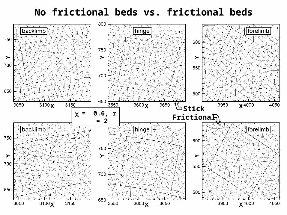
No frictional beds vs. frictional beds
= 0.6, r = 2Stick
Frictional

Fracture evolution: traction vector [h = 30%]
Left lateral (-)
Right lateral (-)
#1 #10 #20 #30
fracture bottom
h = 30%h

Fracture evolution: traction vector [h = 70%]
Left lateral (-)
Right lateral (-)
#1 #10 #20 #30
fracture top
h = 70%h

Fracture evolution: traction vector [h = 30%]
Left lateral (-)
Right lateral (-)
#1 #10 #20 #30
fracture bottom
h = 30%h

Fracture evolution: traction vector [h = 70%]
Left lateral (-)
Right lateral (-)
fracture top
h = 70%h
#1 #10 #20 #30

Fracture evolution: traction vector [h = 30%]
Left lateral (-)
Right lateral (-)
#1 #10 #20 #30
fracture bottom
h = 30%h

Fracture evolution: traction vector [h = 70%]
Left lateral (-)
Right lateral (-)
#1 #10 #20 #30
fracture top
h = 70%h

0.00
0.02
0.04
0.06
0.08
0.10
0 1 2 3 4 5 6 7 8 9 10
r = Ei/Eo
Max
imu
m f
ract
ure
sli
p (
m/m
)
Frictional bedsFrictional bedsFrictional bedsNo frictional bedsNo frictional bedsNo frictional beds
=0.4=0.6
=0.8
0.00
0.02
0.04
0.06
0.08
0.10
0.12
0 1 2 3 4 5 6 7 8 9 10
r = Ei/Eo
Max
imu
m g
ap (
m/m
)
Frictional bedsFrictional bedsFrictional bedsNo frictional bedsNo frictional bedsNo frictional beds
=0.4
=0.6
=0.8
Forelimb
Hinge
Fractures
Fracture reactivation as:
• joints (hinge)
• reverse faults (limbs)

-90
-70
-50
-30
-10
10
30
0 1 2 3 4 5 6 7 8 9 10
r = Ei/Eo
Max
imu
m s
lip
(m
)
Backlimb
Backlimb
Backlimb
Forelimb
Forelimb
Forelimb
=0.6
=0.4
Forelimb =0.8
=0.6
=0.4
=0.8
Backlimb
Maximum slip along bedding surface (interface 2)
Interface 2

-80
-60
-40
-20
0
20
0 1000 2000 3000 4000 5000 6000
Bed
din
g s
urf
ace
slip
(m
)
x = 100%
Interface 2
X (m)
x = 50%
x = 25%
Slip (+)
Slip (-)
Interface 2
Slip along bedding surface (interface 2)

Interface 2
Slip along bedding surface (interface 2 & 3)
Interface 3
-80
-60
-40
-20
0
20
0 1000 2000 3000 4000 5000 6000
Bed
din
g s
urf
ace
slip
(m
)
Interface 2
Interface 3
X (m)
Slip (+)
Slip (-)

• Existing fractures can be reactivated as faults, joints, or shear/opening mode depending in the location of the fracture.
• Opening mode fractures along the hinge
• Fractures in the limbs are predominantly reactivated as reverse faults
• Shearing of fractures is more important along the forelimb than in the backlimb.
• We studied the effect of:• Material properties (stratigraphy)• Parallel slip along bedding surfaces• Overall contraction
Folding and Fracturing: summary and conclusions
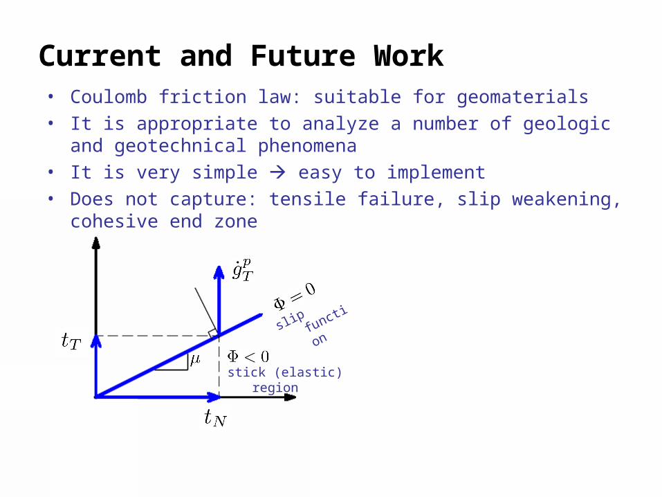
stick (elastic) region
slip function
• Coulomb friction law: suitable for geomaterials• It is appropriate to analyze a number of geologic and geotechnical
phenomena• It is very simple easy to implement• Does not capture: tensile failure, slip weakening, cohesive end zone
Current and Future Work