p5000 em en a · 2008-03-17 · through the whole manual. the p5000 em is designed for marking...
TRANSCRIPT

OPERATING AND MAINTENANCE MANUAL
P5000 EM
MICRO-PERCUSSION MARKING MACHINE
ELECTROMAGNETIC VERSION
Ref
. 921
98 -
P50
00 E
M_e
n_A
- L
ast
up
dat
ed:
03/2
008
www.pro-pen.comPro-Pen reserves all rights to modify its products. This document is non contractual.

Table of contents
A - Introduction .................................................................................................................... 41. Foreward ................................................................................................................................................ 42. Unpacking .............................................................................................................................................. 5� Storage .............................................................................................................................................. 5� Handling the machine ....................................................................................................................... 5� Installation ......................................................................................................................................... 6
3. Identification of the marking equipment .................................................................................................. 64. Power ..................................................................................................................................................... 65. Regulation observance ........................................................................................................................... 6� Declaration of CE compliance ........................................................................................................... 6� Declaration of compliance to other directives .................................................................................. 6� Declaration of compliance to norms .................................................................................................. 7
6. Work station safety ................................................................................................................................. 87. Warranty conditions and operating instructions ..................................................................................... 9
B - Operating instructions for the machine ........................................................................ 101. Description of the machine ................................................................................................................... 102. Technical specifications ....................................................................................................................... 113. Physical characteristics ........................................................................................................................ 114. Dimensional drawings .......................................................................................................................... 11� Dimensional drawings of the machine: P5000EM + EM1/C ............................................................ 11� Dimensional drawings of the machine: P5000EM + EM0/C ............................................................ 12� Dimensional drawings of the table ................................................................................................. 13
5. List of accessories available upon request ........................................................................................... 14
C - Functional definitions ................................................................................................... 171. Circuit connections for the unit .............................................................................................................172. Inside view of the marking head .......................................................................................................... 173. Connections for accessories ................................................................................................................ 18
D - Installation ................................................................................................................... 191. Installation ............................................................................................................................................ 192. Connections ......................................................................................................................................... 19� Safety precautions .......................................................................................................................... 19� View of connectors .......................................................................................................................... 19� Keyboard connection ......................................................................................................................20� Compressed air connection ............................................................................................................ 20� Power supply connection ................................................................................................................ 20� Grounding connection .................................................................................................................... 21
3. Coordinate system ............................................................................................................................... 214. Holding the part to be marked .............................................................................................................. 225. Adjusting the height of the stylus .......................................................................................................... 226. Definition of operating distances of a stylus ......................................................................................... 237. Using the P05 program ........................................................................................................................ 23
E - Marking depth .............................................................................................................. 241. Factors influencing marking depth ....................................................................................................... 24� Choosing the stylus ......................................................................................................................... 24� Distance between the stylus and the part ....................................................................................... 26� Marking force .................................................................................................................................. 27� Choosing the marking speed .......................................................................................................... 27
2. Marking depth ....................................................................................................................................... 27
F - Preventive maintenance .............................................................................................. 281. Every week ........................................................................................................................................... 282. Every three months .............................................................................................................................. 283. Every two years .................................................................................................................................... 29
Ref. 92198 - P5000 EM_en_A 2/36

G - General maintenance .................................................................................................. 301. General information .............................................................................................................................. 302. Detaching the point of the stylus for sharpening .................................................................................. 303. Changing the fuse ................................................................................................................................ 314. Cleaning the sensors ............................................................................................................................ 31
H - Resolution of the problems .......................................................................................... 321. Possible marking problems and problem resolution ............................................................................. 322. What to do if... ...................................................................................................................................... 33
I - Wearing and spare parts ............................................................................................... 341. Spare parts ........................................................................................................................................... 342. Consumables ...................................................................................................................................... 34
J - Noise emission of the machine .................................................................................... 351. Test code .............................................................................................................................................. 35� Measurement method ..................................................................................................................... 35� Definition of the microphone position .............................................................................................. 35� Test conditions ................................................................................................................................ 35
2. Noise emission information .................................................................................................................. 35
K - Appendix ...................................................................................................................... 36
Ref. 92198 - P5000 EM_en_A 3/36

AAIntroduction
1. Foreward
Before reading this manual, view the start-up CD ROM and try to execute the test marking suggested. Then, read through the whole manual.
The P5000 EM is designed for marking applications. If used for other purposes, Pro-Pen cannot guarantee the quality of the result. Pro-Pen is not responsible for damage caused by inappropriate use of the machine.
Four icons indicate important points:
Work station safety:
Indicates different safety precautions to be taken during installation and operation of the machine.
Instructions for use and warranty limitations:
Indicates different operating procedures which respect warranty conditions.
Operating instructions:
These tips help optimize the machine’s performance.
What to do if...
This icon refers to the last chapter which describes the actions to be carried out in the event of a problem or breakdown on the marking equipment.
Ref. 92198 - P5000 EM_en_A 4/36

AIntroduction A
2. Unpacking1 : Wedge 2 : 1 packaged keyboard + keyboard function strip 3 : Machine: P5000 EM + 1 stylus 4 : Contents of the box
- power cable - 1 CD-ROM with user manual - 1 instruction card - 1 test plate for the machine - 1 stainless steel plate for marking practice - CAN plug - 1 bridged male SubD9 connector, for the reset function - additional accessories if ordered
� Storage
Keep the packing in case the machine has to be returned.
� Handling the machine
There is an M10x20 handling hole on the top of the P5000. Use a lifting ring capable of sustaining 230 DaN (517.061 lb) to comply with standard NFX35-109. Pro-Pen can provide an M10x20 ring as an option (ref. MCM08/3140).
P5000EM: Weight: 34 kg (74.957 lb) If it is necessary to unpack the machine without the aid of a mechanical lift, it is recommended to use two persons wearing safety shoes.
Take the machine out of its package before hooking it to a mechanical lift. Unpack the machine with 2 operators.
1
2
3
4
Ref. 92198 - P5000 EM_en_A 5/36

AIntroduction A
� Installation• Unpack the machine with 2 operators. Put the machine on its feet.
• The hand crank must not cover the M10x20 hole located on the top of the column (Z axis).
• Screw the lifting ring firmly and completely into the column.
• Use the lifting ring to carry the machine to its installation location.
3. Identification of the marking equipment
The marking equipment is identified by:
• 1 identifcation plate on the marking head
Have the model and serial number of the equipment ready to give to Pro-Pen each time you are in contact.
4. Power
• power supply: 115 V / 230 V
• power: 360 W
• frequency: 50 -60 Hz
5. Regulation observance
Manufacturer, TECHNIFOR SAS - 114, quai du Rhône - 01708 MIRIBEL CEDEX - France declares:
� Declaration of compliance
CE marking on the equipment attests the observance of the following European directives:
• Directive 98/37/EC of the European Parliament and of the Council of 22 June 1998, concerning the consolida-tion of the laws of member states relating to the machines.
• Directive 2006/95/EC of the European Parliament and of the Council of 12 december 2006 on the harmonisa-tion of the laws of the Member States relating to electrical equipment designed for use within certain voltage limits.
• Directive 2004/108/EC of the European Parliament and of the Council of 15 december 2004 on the harmonisa-tion of the laws of the Member States relating to electromagnetic compatibility.
� Declaration of compliance to other directives
Equipment is compliant with the following European directives:
• amended Directive 2002/95/EC of the European Parliament and of the Council of 27 January 2003 restricting the use of some dangerous substances present in electrical and electronical equipment (RoHS).
• amended Directive 2002/96/EC of the European Parliament and of the Council of 27 January 2003 on waste electrical and electronic equipment (WEEE).
Ref. 92198 - P5000 EM_en_A 6/36

AIntroduction A
Waste Electronic and Electrical EquipmentThis symbol indicates that once this equipment has reached the end of its useful life, it must not be disposed of with non-sorted municipal waste, in accordance with European Directive 2002/96/EC.
The equipment must be disposed of at an appropriate collection point for processing, sorting, and recycling of Waste Electronic and Electrical Equipment (WEEE).
The elements which compose Waste Electronic and Electrical Equipment (WEEE) may contain substances which have harmful effects on the environment or on human health.
By following these instructions, you are helping the environment, contributing to the preservation of our natural resources, and protecting human health.
� Declaration of compliance to norms
The equipment is compliant with the following norms:
• Standard NF EN 61000-6-2 of January 2006 concerning electromagnetic compatibility (EMC) - Part 6-2: generic standards- Immunity for industrial environments.
• Standard NF EN 61000-6-4 of March 2007 concerning electromagnetic compatibility (EMC) - Part 6-4: generic standards- Standard on emissions for industrial environments.
The modification or transformation of this equipment, adaptation and accessory installation unrecommended by Pro-Pen modify this equipment’s characteristics and therefore void the compliance with the applicable EU directives. These modifications void Pro-Pen’s liability. In this case, the machine and equipment installer is responsible for the final work station’s compliance.
Ref. 92198 - P5000 EM_en_A 7/36

AIntroduction A
6. Work station safetyTo ensure security and productivity, read this manual before starting-up the equipment.
• This marking equipment is designed to function at a room temperature between 5 0C
(41 0F) to 45 0C (113 0F).
• Do not use this marking equipment in an explosive environment.
• Grounding must be done according to the regulations in effect to ensure the safety of the personnel. The connection to the single phase power supply is made with a standard, 3 pin plug with grounding. It must be equipped with an adequately calibrated 30 mA differential cut-off and protection device.
• This marking equipment is not designed to operate in damp premises.
• During marking, do not place fingers or objects in the area reserved for stylus movement. Keep hands away from the marking zone. Disregard for this recommendation may result in the operator being lightly pinched by the point of the stylus.
• Depending on the application (tooling or heavy parts), it is recommended to wear safety shoes and work gloves.
• Do not remove the power supply cover: electrocution risk.
• In case of a long marking cycle or fast pace, the stylus’ temperature can reach 100 0C
(212 0F). Beyond this temperature, the system is in security mode. Use a cooling system in a high temperature environment.
• The air exhaust from the stylus can project metal dust or chips, if necessary wear safety glasses (in the event of the stylus cooling by compressed air).
At the time of disposal, wearing personal protective equipment (PPE) is recommended to dismantle the mechanical elements of the machine. Some guiding elements (pinions, bearings, bars) are dismantled while hot and may release toxic fumes.
Ref. 92198 - P5000 EM_en_A 8/36

AIntroduction A
7. Warranty conditions and operating instructionsThis equipment is designed to mark material using Pro-Pen electromagnetic styli only. Any other use, or the use of styli other than those provided by Pro-Pen is not recommended. Pro-Pen will not be held responsible for the results.
Pro-Pen will not be held responsible for injuries resulting from disregard for the above operating instructions or other general safety rules applicable to the use of this equipment. Furthermore, disregard for the instructions will void the warranty.
For more information, please refer to the warranty details delivered with the machine.
• The compressed air system must meet all standards (in the event of the stylus cooling by compressed air).
• Never lubricate any part of the stylus or carriage guide bars.
When marking or doing test marking, the stylus must always have a part under it with which to make contact.
If it strikes only air, these are the risks:
• mechanical deterioration of moving parts
• void of the manufacturer’s guarantee
Ref. 92198 - P5000 EM_en_A 9/36

BBOperating instructions for the machine
1. Description of the machine
The P5000 EM is a digitally controlled micro-percussion marking machine.
The marking head is attached to a column stand with a Z axis. The Z axis is adjusted manually using the crank handle and the ruler along the frame for positioning.
This machine works by moving the stylus along the X and Y axes of a grid.
The control electronics and the screen are integrated.
This combination of technologies allows for rapid marking of alphanumeric characters and logos.
The LCD screen is located on the front of the machine. The same keyboard used for a PC connects to the top of the marking head.
As an option, a PC linked to the control board by an RS232 connection, can be used to manage marking thanks to the program developed in a Windows® environment.
1 : Z axis crank handle 2 : Ruler 3 : Marking head 4 : LCD screen 5 : Electromagnetic stylus 6 : CAN plug
1
2
3
4
5
6
Ref. 92198 - P5000 EM_en_A 10/36

AOperating instructions for the machine B
2. Technical Specifications• marking area: 100 mm (3.937 in) x 120 mm (4.724 in)
• stylus EM1/C
• fonts available:
- continuous action, dot by dot: norme 5x7 - size: from 0.5 mm (0.02 in) to 100 mm (3.937 in) mm with increments of 0.1 mm (5/1000 in) - characters: those included in the basic multilingual diagram of the Unicode standard (ISO 10646)
• dates, counters, batch numbers, shift codes, logos...
• maximum movement speed: 300 mm (11.811 in) per second
3. Physical characteristics
• dimensions (L x w x h): 601 mm (23.661 in) x 327.5 mm (12.894 in) x 734 mm (28.898 in)
• weight: 34 kg (74.957 lb)
4. Dimensional drawings
� Dimensional drawings of the machine: P5000EM + EM1/C
1 : Marking area: 100 mm (3.937 in) x 120 mm (4.724 in) 2 : CAN plug 3 : Electromagnetic stylus: EM1/C
Ref. 92198 - P5000 EM_en_A 11/36

AOperating instructions for the machine B
� Dimensional drawings of the machine: P5000EM + EM0/C4 : Marking area: 100 mm (3.937 in) x 120 mm (4.724 in) 5 : CAN plug 6 : Electromagnetic stylus: EM0/C
Ref. 92198 - P5000 EM_en_A 12/36
AOperating instructions for the machine B
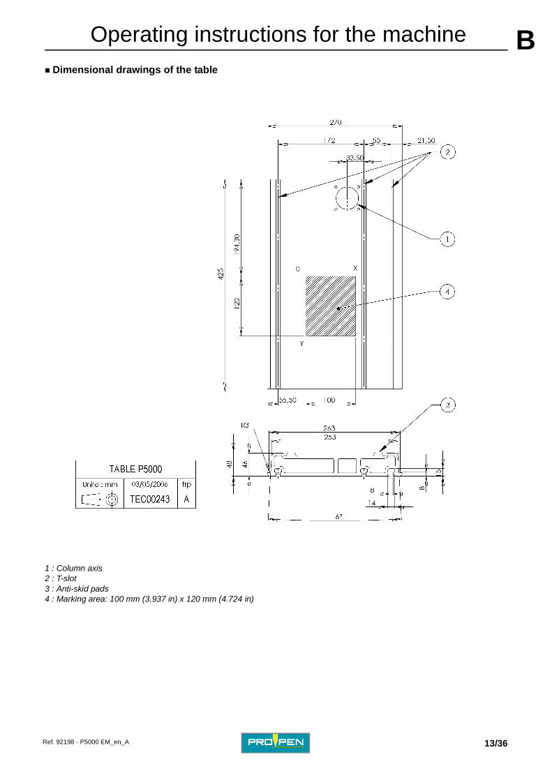
� Dimensional drawings of the table1 : Column axis 2 : T-slot 3 : Anti-skid pads 4 : Marking area: 100 mm (3.937 in) x 120 mm (4.724 in)
Ref. 92198 - P5000 EM_en_A 13/36

AOperating instructions for the machine B
5. List of accessories available upon requestStart cycle foot pedal
Button box for start cycle/emergency stop
Plate holder
Magnetic plate clamp
Ref. 25053 • Office footswitch:A simple touch of the pedal will launch a marking "n" times, leaving the operator with both hands free. The foot pedal is not designed to stop marking.
Ref. 25054 • Industrial footswitch:
Same use as described above. This foot pedal is especially designed for industrial work environments or for high rate production. Unlike the office footswitch, a double action avoids untimely triggering.
Ref. 25055 • The green button is used to launch marking (same function as the foot pedal).
• The red button is used to stop either a single marking in progress or a series of markings before it reaches the end.
After pushing the emergency stop button, the green button cannot be used to restart marking. In this case, use the keyboard.
Ref. 2509 • Sound-proof plate holder:
This accessory reduces the noise level during marking.
Ref. 25153 • Raised plate holder:This accessory is used to be able to mark plates without having to take down the DP3500/TAG3500 accessory.
Ref. 2508 • As a complement to the sound-proof plate holder, it is used to clamp parts on a steel support.
Ref. 92198 - P5000 EM_en_A 14/36

AOperating instructions for the machine B
Circular marking deviceProgram PW05
TAG 3500
Protective cover
Marking zone lighting
Ref. 25170 LXX
• DP3500: This accessory is used to rotate a part under the marking head in order to mark the circumference. Maximum moment of inertia of the part:
• without chuck: 65 kg.cm2
• with chuck: 50 kg.cm2
Ref. 25180 LXX
• DP4500:
This accessory is used to rotate a part under the marking head in order to mark the circumference.
Ref. 25158 Ref. 25159 (USB)
• Developed in a Windows environment, this program combines all the capabilities and user-friendliness of a PC.
• An unlimited number of files can be seen on the screen.
• Exists with a USB or parallel protection key.
Ref. 25178 LXX
• This accessory is used to automatically feed identification plates to the machine.
Ref. 2743 • This accessory is used to protect the machine from dust.
Ref. 25154 • This accessory is used to light the marking area using a high power LED lodged under the marking head.
Ref. 92198 - P5000 EM_en_A 15/36

AOperating instructions for the machine B
Other accessoriesRef. Contact us. Electromagnetic stylus: EM0/C
Ref. 2427 Electromagnetic stylus: EM1/C
Ref. Contact us. Points for EM0/C stylus: 90°
Ref. 2685 Points for EM1/C stylus: 90°
Ref. 92101 1 instruction card
Ref. 92198 Operating and maintenance manual
Ref. 2620 Stainless steel plates in credit card format, pack of 50
Ref. 25121 Bar code reader Scanplus 1800SR [reads 10 cm (3.937 in)]
Ref. 25122 230 V power supply for bar code reader
Ref. 25124 115 V power supply for bar code reader
Ref. 92198 - P5000 EM_en_A 16/36
CCFunctional definitions
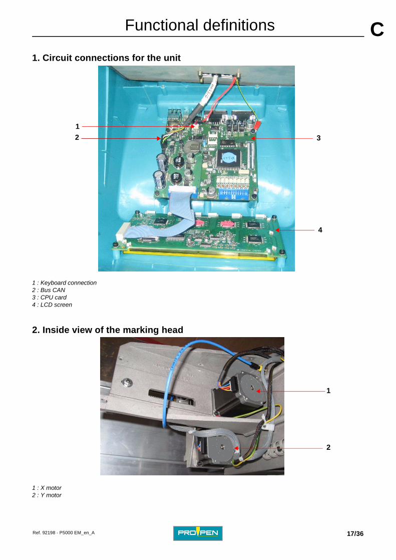
1. Circuit connections for the unit
1 : Keyboard connection 2 : Bus CAN 3 : CPU card 4 : LCD screen
2. Inside view of the marking head
1 : X motor 2 : Y motor
1
2 3
4
1
2
Ref. 92198 - P5000 EM_en_A 17/36

AFunctional definitions C
3. Connections for accessories1 : Accessory connection (start cycle/emergency stop button box or start cycle foot pedal...) or 1 bridged male SubD9 connector, for the reset function
2 : RS232 connection for communication with PC 3 : USB_B connection DEVICE (PC link) 4 : USB_A connection HOST (marking file on key) 5 : Ethernet connection 6 : Connection for circular marking device (Remove the plug from the machine.)
1
2
3
4
5
6
Ref. 92198 - P5000 EM_en_A 18/36
DDInstallation
1. Installation
Unpack the machine and install it at the work station.
The machine must be installed in a workspace allowing the operator easy access to the adjustment handle for the Z-axis and clear visibility of the marking area where the stylus is moving. The marking area must be easily accessible.
2. Connections
� Safety precautions
� View of connectors
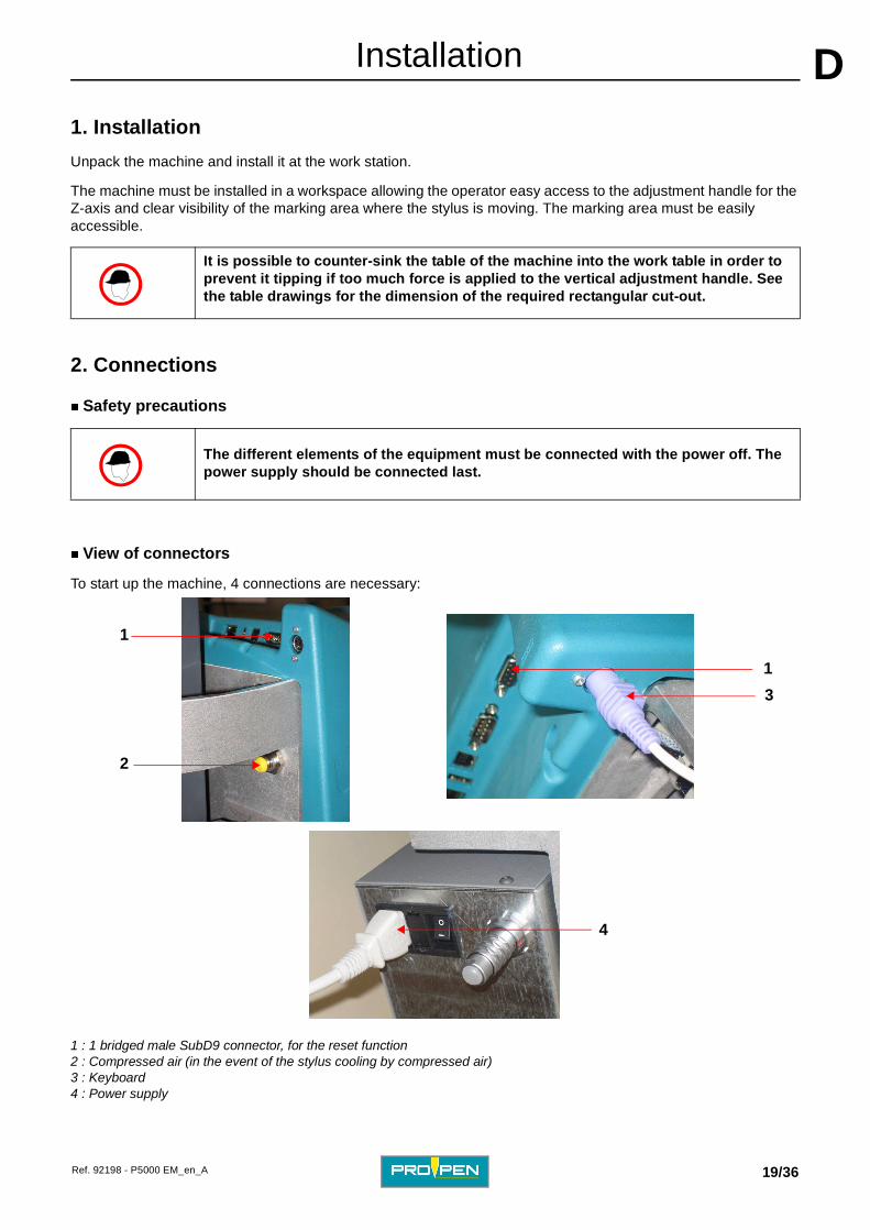
To start up the machine, 4 connections are necessary:
1 : 1 bridged male SubD9 connector, for the reset function 2 : Compressed air (in the event of the stylus cooling by compressed air)3 : Keyboard 4 : Power supply
It is possible to counter-sink the table of the machine into the work table in order to prevent it tipping if too much force is applied to the vertical adjustment handle. See the table drawings for the dimension of the required rectangular cut-out.
The different elements of the equipment must be connected with the power off. The power supply should be connected last.
2
3
4
1
1
Ref. 92198 - P5000 EM_en_A 19/36

AInstallation D
� Keyboard connectionConnect the keyboard connector socket to the machine.
There is a female connector, type DIN, on the electronics board.
� Compressed air connection (in the event of the stylus cooling by compressed air)
Foresee an air inlet pipe, 6 mm (0.236 in) diameter for the pneumatic cooling of the stylus. (instant connector)
� Power supply connection
This machine comes equipped with an SMPS (switch mode power supply). No power supply voltage adjustment is necessary.
However, if the machine doesn’t start (screen off, power supply ventilator not running...):
• Check that the power cord is correctly plugged in to both the machine and the power supply.
• Check that the switch is in the "I" position (On).
• Check the condition of the fuse.
- Unplug the power supply cord. Put the On/Off switch in the "O" (Off) position. - Remove the fuse carrier (1) located below the power filter. - If necessary, replace the fuse (2) with a new one (4 A TT) and plug the machine back in.
1 : Fuse carrier 2 : Fuse
The ideal air pressure is 4 Bar (58.015 PSI) - 6 Bar (87.023 PSI).
• The compressed air system must meet all standards.
1 2
Ref. 92198 - P5000 EM_en_A 20/36
AInstallation D
� Grounding connection3. Coordinate system
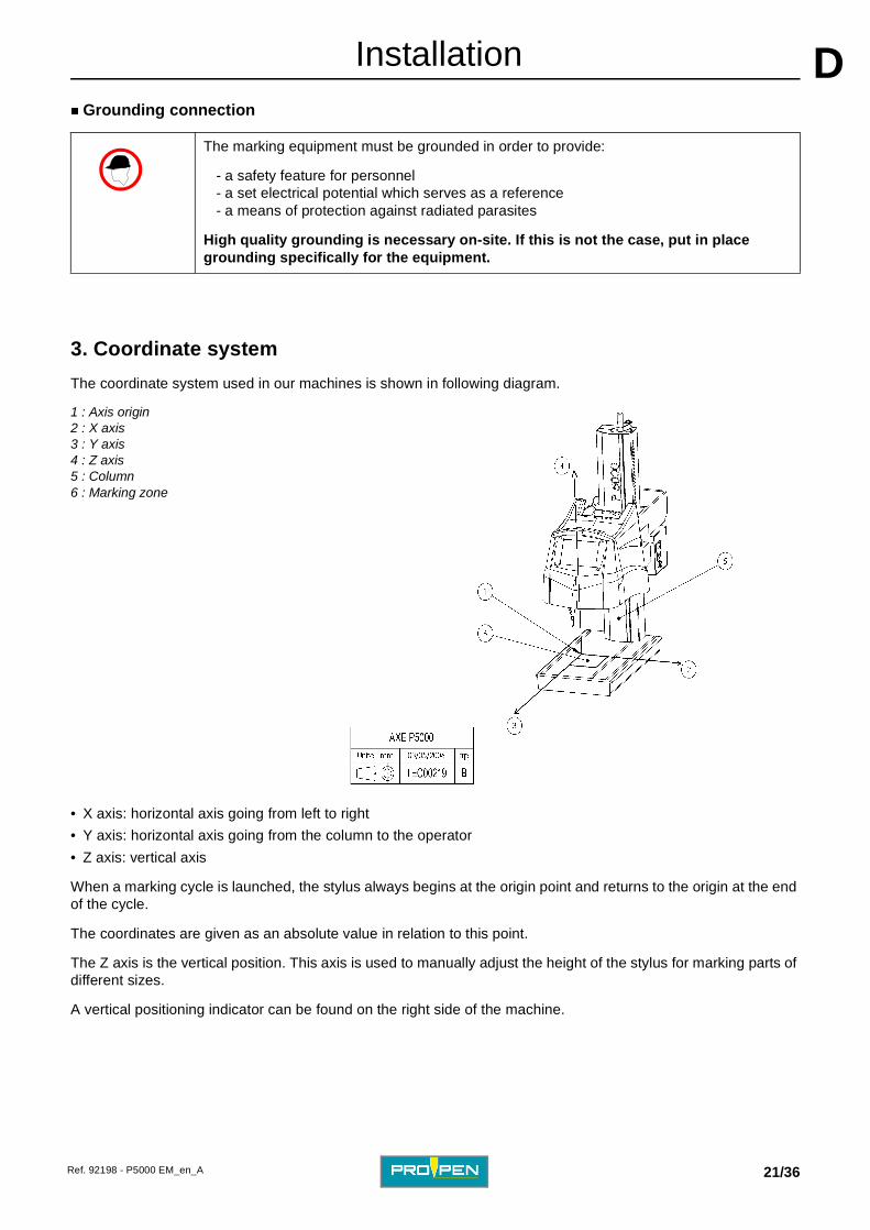
The coordinate system used in our machines is shown in following diagram.
1 : Axis origin 2 : X axis 3 : Y axis 4 : Z axis 5 : Column 6 : Marking zone
• X axis: horizontal axis going from left to right
• Y axis: horizontal axis going from the column to the operator
• Z axis: vertical axis
When a marking cycle is launched, the stylus always begins at the origin point and returns to the origin at the end of the cycle.
The coordinates are given as an absolute value in relation to this point.
The Z axis is the vertical position. This axis is used to manually adjust the height of the stylus for marking parts of different sizes.
A vertical positioning indicator can be found on the right side of the machine.
The marking equipment must be grounded in order to provide:
- a safety feature for personnel - a set electrical potential which serves as a reference - a means of protection against radiated parasites
High quality grounding is necessary on-site. If this is not the case, put in place grounding specifically for the equipment.
Ref. 92198 - P5000 EM_en_A 21/36

AInstallation D
4. Hold the part to be markedSituation 1
Used with Pro-Pen plate-holder (optional)
To mark plates or small parts with a thickness of less than 2 mm (0.079 in), use the plate holder to position the parts and prevent them from vibrating when the stylus taps.
Situation 2
No plate-holder used
To mark small or large parts, create the necessary tooling to position and clamp the parts under the machine. If the part is flexible, this tooling must provide firm support under the part to be marked. It must be held on the worktable using the three T grooves. The position of the marking zone with relation to the T grooves is indicated on the dimensional drawing of the worktable.
5. Adjusting the height of the stylus
Determining the optimum operating distance of the stylus according to the part to be marked.
This distance is between 1 mm (0.039 in) and 5 mm (0.197 in).
Using feeler gauges, position the point of the stylus 4 mm (0.157 in) above the part to be marked.
Execute a marking.
The whole marking line should be legible.
Depending on the results, increase or decrease the distance between the stylus and the marking surface.
A poorly clamped piece can generate high sound levels, thus becoming harmful after long periods.
• If a stylus is set too high, it doesn’t mark because the point doesn’t touch the plate consistently while tracing the characters.
• If the stylus is set too low, it doesn’t mark because it cannot vibrate. The point withdraws inside the stylus and remains in permanent contact with the plate.
Ref. 92198 - P5000 EM_en_A 22/36

AInstallation D
6. Definition of operating distances of a stylus7. Using the P05 program
Refer to the user manual for the P05 program.
Max. distance
DM
Maximum adjustment distance
Carry out a series of markings while progressively lowering the head until a uniform marking is obtained. With the help of feeler gauges, measure the distance between the point of the stylus at rest and the marked surface. Make a note of this distance.
Min. distance
Dm
Minimum adjustment distance
Lower the head until the stylus is barely touching the part to be marked. Raise the head and set the distance from the point of the stylus to the surface to be marked at Do (optimal distance), between 0.5 mm (0.02 in) and 1 mm (0.039 in).
Amplitude
A
Amplitude of a stylus
Subtract the min. distance (Dm) from the max. distance (DM) to obtain the operating amplitude of the stylus. This distance corresponds to its operating range, or its capacity to absorb variations in flatness.
Reference distance
Do
Optimum adjustment distance
Take the average of the DM and Dm. Position the stylus at this distance (Do).
The max. distance (DM) and min. distance (Dm) may vary slightly from one stylus to another (production tolerances for stylus components, pressure and compressed air flow through the system).
To mark curved parts using the maximum amplitude (A), set the stylus at the minimum distance (Dm) above the highest point of the part.
Ref. 92198 - P5000 EM_en_A 23/36

EEMarking depth
1. Factors influencing marking depth
The principle factors are:
• choosing the stylus
• distance between the stylus and the part
• marking force
• choosing the marking speed
� Choosing the stylus
2 electromagnetic styli of different powers are available: EM0/C - EM1/C. The force varies according to the diameter of the tip of the point.
The points come sharpened to a radius of 0.2 mm (0.008 in). Depending on the need, points can be sharpened to different radii ranging from 0.1 mm (0.004 in) to 0.5 mm (0.02 in).
A EM1/C stylus with a point radius sharpened to 0.2 mm (0.008 in) comes standard with the machine. This point is suitable for most common marking needs.
A EM0/C stylus is available upon request.
To avoid creating stress on fragile parts, choose the following marking parameters:
• stylus EM0/C is the preferable choice
• choose a point with the largest possible radius
• select marking force 25% for the marking file
For very fragile parts, validate marking with mechanical resistance tests.
Ref. 92198 - P5000 EM_en_A 24/36

AMarking depth E
Stylus EM1/C1 : X Carriage 2 : Cooling kit for cooled version 3 : Protection tube 4 : Sensor option of the motorized Z-axis 5 : Coil 6 : Stylus nose 7 : Point 8 : Stylus fixture screw 9 : Electrical cable output 10 : Compressed air supply (in the event of the stylus cooling by compressed air)
Ref. 92198 - P5000 EM_en_A 25/36
AMarking depth E
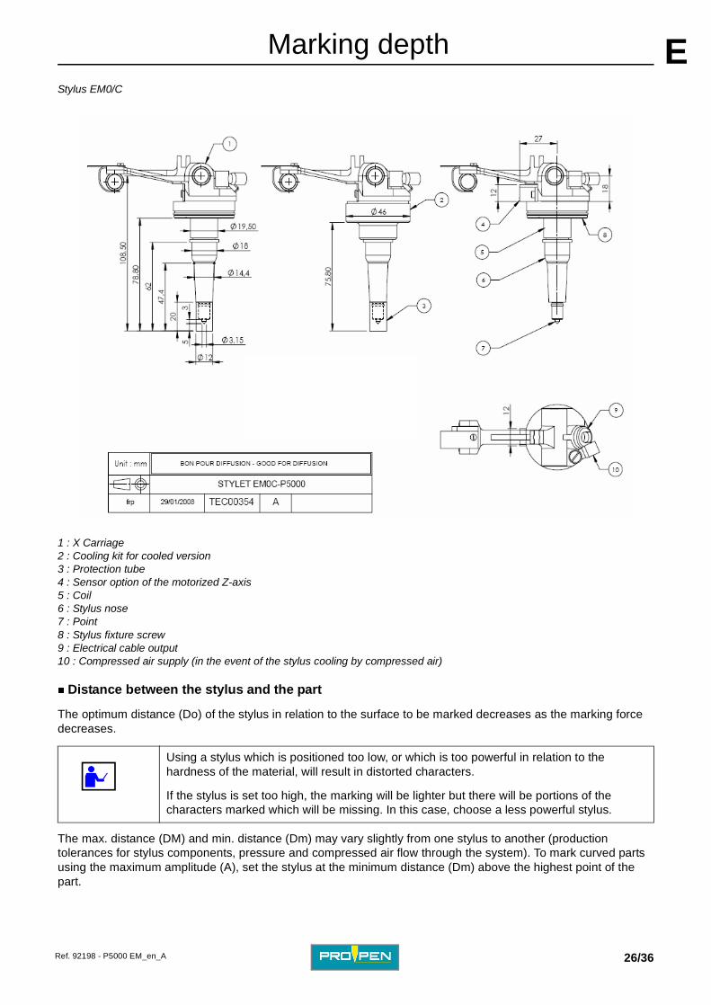
Stylus EM0/C1 : X Carriage 2 : Cooling kit for cooled version 3 : Protection tube 4 : Sensor option of the motorized Z-axis 5 : Coil 6 : Stylus nose 7 : Point 8 : Stylus fixture screw 9 : Electrical cable output 10 : Compressed air supply (in the event of the stylus cooling by compressed air)
� Distance between the stylus and the part
The optimum distance (Do) of the stylus in relation to the surface to be marked decreases as the marking force decreases.
The max. distance (DM) and min. distance (Dm) may vary slightly from one stylus to another (production tolerances for stylus components, pressure and compressed air flow through the system). To mark curved parts using the maximum amplitude (A), set the stylus at the minimum distance (Dm) above the highest point of the part.
Using a stylus which is positioned too low, or which is too powerful in relation to the hardness of the material, will result in distorted characters.
If the stylus is set too high, the marking will be lighter but there will be portions of the characters marked which will be missing. In this case, choose a less powerful stylus.
Ref. 92198 - P5000 EM_en_A 26/36
AMarking depth E
� Marking forceThe width and depth of the marked line varies with the defined value.
The higher the force, the deeper the mark. This value is expressed as a percent.
� Choosing the marking speed
There are 10 speeds:
The choice of speeds influences the marking quality.
2. Marking depth
A metallographic test is performed to measure marking depth. This process is used to dissuade attempts to falsify the marking.
Different definitions concerning marking depth
Marking speed Result Speed Marking cycle
1 to 3 Very high quality Slow Long
4 to 7 High quality Fast Standard
8 to 10 Average quality Very fast Short
P1 = depth of marking P2 = depth of penetration P3 = depth of warping
1 : Solid material 2 : Thin sheet metal 3 : Embossing
Ref. 92198 - P5000 EM_en_A 27/36

FFPreventive maintenance The maintenance operations listed here are intended as a guideline, and should be implemented upon reception of the material. In a highly polluted environment, these operations may need to be performed more frequently.
This maintenance list was established based on a marking frequency of:
• 520 000 cycles per year (7 800 000 characters per year)
• 15 characters 3 mm (0.118 in) high per cycle
• 8 continuous working hours on steel strength 50 DaN/mm2 (72518.869 lb/in2)
1. Every week
• Clean the guide bars inside the marking head with a dry cloth (no solvent, oil, or grease).
• To have access to the point, manually unscrew the stylus nose. Remove the point.
• Check the condition of the stylus, then clean it thoroughly.
• Clean the point with a dry cloth.
1 : X carriage guide bars 2 : Y carriage guide bars 3 : Stylus nose
2. Every three months
• Have the stylus serviced by Pro-Pen. Check the belt tension.
Unplug the power supply plug before beginning any cleaning or maintenance operation.
1
2 3
Ref. 92198 - P5000 EM_en_A 28/36

APreventive maintenance F
3. Every two yearsHave the marking head serviced by Pro-Pen.
This operation includes:
• complete dismantling of the machine
• cleaning of the mechanical elements
• standard replacement of X and Y carriages
• replacement of the guide bars and belts
• verification of the condition of X and Y motors and belts
• reassembly and adjustment of mechanical elements
• debugging of the head in an enclosure
• marking tests
Ref. 92198 - P5000 EM_en_A 29/36

GGGeneral maintenance
1. General information
Maintenance consists of regular monitoring of marking quality. Intensive use of the equipment can impact the guiding systems of the carriage or the stylus point, and may result in distortion of the characters.
Contact your distributor to schedule an appointment for servicing. This "tune-up" does not take a long time.
Check the compressed air system regularly. Based on the level of soiling, establish a schedule for cleaning or replacement.
Never lubricate any part of the stylus or carriage guide bars.
2. Detaching the point of the stylus for sharpening
The tip of the point is made from a grade of carbide suitable for creating impacts. The point should be rounded in order to hold up well on hard material.
To have access to the point, manually unscrew the stylus nose.
• Never lubricate any elements of the stylus.
• Never use pliers to tighten the stylus.
• Never lubricate any element of the marking head.
Unplug the power supply plug before beginning any cleaning or maintenance operation.
Ref. 92198 - P5000 EM_en_A 30/36
AGeneral maintenance G
3. Changing the fuseDisassemble the power filter located on the side of the machine.
Use a screwdriver to change the fuse. Remove the fuse from its housing and replace it with the new one.
Choosing the fuse
1 : Fuse carrier 2 : Filter
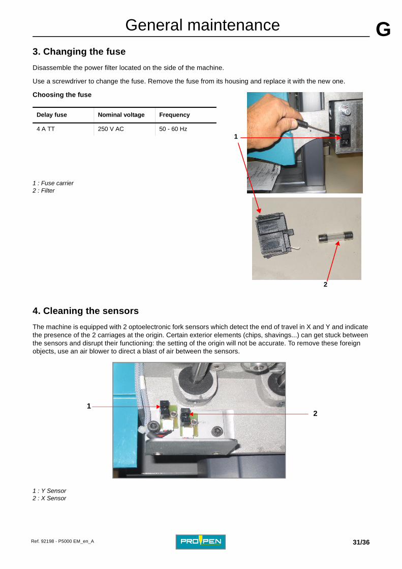
4. Cleaning the sensors
The machine is equipped with 2 optoelectronic fork sensors which detect the end of travel in X and Y and indicate the presence of the 2 carriages at the origin. Certain exterior elements (chips, shavings...) can get stuck between the sensors and disrupt their functioning: the setting of the origin will not be accurate. To remove these foreign objects, use an air blower to direct a blast of air between the sensors.
1 : Y Sensor 2 : X Sensor
Delay fuse Nominal voltage Frequency
4 A TT 250 V AC 50 - 60 Hz
2
1
12
Ref. 92198 - P5000 EM_en_A 31/36

HHResolution of the problems
1. Possible marking problems and problem resolution
Situation Description Diagnosis Action
1 The stylus is not vibrating sufficiently and the part is not marked.
The stylus is too close to the surface to be marked.
Raise the marking head, then try marking again.
2 The point of the stylus doesn’t mark the part.
The stylus is too far from the surface to be marked.
Lower the marking head, then try marking again.
3 Intermittent characters The point of the stylus was oiled or lubricated.
Dismantle the stylus. Remove the point. Clean the point with a dry cloth. Reassemble the stylus.
4 Only the upper, or lower, part of the characters are marked.
The part doesn’t have a constant thickness in the Y direction.
Use feeler gauges to reposition the part so that it is level.
5 Only the left, or right, part of the characters is marked.
The part doesn’t have a constant thickness in the X direction.
Use feeler gauges to reposition the part so that it is level.
Ref. 92198 - P5000 EM_en_A 32/36

AResolution of the problems H
2. What to do if...Situation Description Things to check Action
1 The screen on the front of the machine is blank.
Is the power supply switched on? Is the cable properly connected? Is the On/Off switch in the On position? Is the fuse on the back of the machine in good condition?
See: Power supply connectionSee: Changing the fuse
2 One of the carriages, X or Y, does not return to the origin when the start marking command is given.
• The sensors are dirty. • The machine’s mechanics are obstructed.
• Clean the sensor by directing a blast of air inside the fork with an air gun. • Turn off the machine and move both carriages until the stylus is in the middle of its travel. Try to execute another marking.
3 Lost in the program? Refer to the manual. Press Esc and answer "no" to the questions from the program until you’re back to the main menu.
4 Marking doesn’t start. / No access to the "Marking" menu
The bridged male Sub-D9 con-nector or on one of the acces-sories is not connected.
Connect the Sub-D9 bridged con-nector or the accessory.
5 Irregular marking The CAN plug is not connected. Connect the CAN plug.
Ref. 92198 - P5000 EM_en_A 33/36

IIWearing and spare parts Please give the item codes with your order to speed processing.
1. Spare parts
These parts may present a risk for breakdown under normal operating conditions of the machine. Mechanical parts are excluded since in theory they are not considered a potential cause for breakdown.
2. Consumables
Reference Description
92067 LCD screen
2757 (USA), 2755 (UK)
Keyboard and functions strip
2742 Head casing with decals
3157 Column casing with decals
90020 Z axis crank handle
4020 Aluminum work table
90012 Rubber pads (4)
Reference Description
2685 Points for EM1/C stylus
2688 Repair kit stylus EM1/C (seal + spring + washer)
4225 Fuse 4 A TT
Ref. 92198 - P5000 EM_en_A 34/36

JJNoise emission of the machine
1. Test code
� Measurement method
The measurements were taken according to the regulations of standard NF EN ISO 11201:1996.
Measurement equipment used:
• 01dB - Stell intergrated sonometer,SIP 95 S, # 20394
• Cal 01 calibrator, # 40141
Material used for marking:
• type P5000 EM machine mounted on a column stand
The unit is placed on a wood workbench in a workshop where the background noise level is negligible compared with the noise emitted by the machine. The work station, situated more than 2 m (6.562 ft) from any separator, is designed for a standing operator.
The marking is carried out using a EM1/C stylus on a steel plate with dimensions of 110 mm (4.331 in) x 100 mm (3.937 in) x 3 mm (0.118 in) clamped to a base support. A new plate is used for each test.
� Definition of the microphone position
The microphone is positioned 1 m (3.281 ft) in front of the machine and 1.6 m (5.249 ft) from the floor.
� Test conditions
• marking speed: 100%
• stroke force: 50%
• marking of 3 lines of 18 characters 5 mm (0.197 in) high
• steel plate with dimensions 110 mm (4.331 in) x 100 mm (3.937 in) x 3 mm (0.118 in)
2. Noise emission information
The values given below represent the noise emitted by the machine during marking. When the machine is in use, the values mentioned are independent from the total noise level to which the operator is exposed, since the actual noise level will vary depending on the operator’s environment.
• Average level: LAeq = 76 dB(A)
(LAeq = "equivalent" average sound level measured using the A-weighting)
• Peak level: Lpc < 108 dB(C)
(Lpc = peak acoustic pressure level)
When marking resonant parts (metallic, hollow, thin), wear hearing protection for sound levels LAeq > 85 dB(A) or Lpc > 137 dB(C).
Ref. 92198 - P5000 EM_en_A 35/36

KKAppendix To contact the Pro-Pen Group
FRANCEPRO-PEN
114, quai du Rhône01708 MIRIBEL Cedex
Tel.: 33 (0)4 78 55 85 63Fax: 33 (0)4 78 55 85 66
E-mail: [email protected]
U.S.A.Technifor Inc.
9800-J Southern Pine BoulevardCharlotte, NC 28273
Tel.: (1) 704 525 5230Fax: (1) 704 525 5240
E-mail: [email protected]
ENGLANDTechnifor Ltd
Unit 3 Trojan Business CentreTachbrook Park Estate
LEAMINGTON SPACV34V 6RH WarwickshireTel.: (44) 19 26 88 44 11Fax: (44) 19 26 88 31 05
E-mail: [email protected]
GERMANYPRO-PEN
MarkierungsgeräteMauserstraße 13
D-71640 LUDWIGSBURGService Tel.-Nr: (49) 71 41 29 80 98-18
Tel.: (49) 71 41 29 80 98-14Fax: (49) 71 41 29 80 98-20
E-mail: [email protected]
ITALYPRO-PEN
Via Rivera, 13810040 ALMESE (TO)
Tel.: (39) 011 935 27 14Fax: (39) 011 934 59 42E-mail: [email protected]
SPAINPRO-PEN
C/ Sant Iscle, 29 bajos B08031 BARCELONA
Tel.: (34) 93 407 07 51Fax: (34) 93 407 17 26
E-mail: [email protected]
BRAZILPRO-PEN
Av. Dr. Luis Arrobas Martins, 9804781-000 - SAO PAULO SP
Tel.: (55) 11 5541 74 93Fax: (55) 11 5541 74 93
E-mail: [email protected]
SWITZERLANDTechnifor Gravograph
Champ Olivier 2Ch 3280 MORAT
Tel.: (41) 26 678 7200Fax: (41) 26 678 7222
E-mail: [email protected]
MALAYSIAGravoTech Sdn Bhd
No. 29, Jalan Puteri 5/10Bandar Puteri
47100 PUCHONG, SELANGORTel.: (60) 3 80 685512 & 80 683512
Fax: (60) 3 80 612513E-mail: [email protected]
JAPANTechnifor KK
1-25 Takahata-ChoNISHINOMIYA-SHI, HYOGO
663-8202Tel.: (81) 798 63 7325Fax: (81) 798 63 6280
E-mail: [email protected]
SINGAPOREGravograph Singapore Pte Ltd
No6, New Industrial Road#07-03/04 Hoe Huat Industrial Buildind
536199 SINGAPORETel.: (65) 6289 4011Fax: (65) 6289 4211
E-mail: [email protected]
CHINAGravoTech Engraving Equipment Co. Ltd
N. 3388 Humin Road, Minhang DistrictSHANGHAI 201108
Tel.: (86) 21 / 51 59 18 28Fax: (86) 21 / 51 59 18 22
E-mail: [email protected]
AUSTRALIATechnifor Gravograph
Unit 3, 7-11 South StreetRYDALMERE N.S.W. 2116
Tel.: (61) 29 684 2400Fax: (61) 29 684 2500
E-mail: [email protected]
INDIAGravotech Engineering PVT Ltd
Gat n° 2323/1 - Reality WarehouseNagar Road - Haveli Taluka - Wagholi
PUNE 412 207Tel.: (91) 20 / 329 18 577 / 21 482
Fax: (91) 20 / 660 324 25E-mail: [email protected]
SWEDENGravoTech Nordrad ABVretenborgsvägen, 28
SE-126 30 HÄGERSTENTel.: (46) 8 658 15 60Fax: (46) 8 658 15 64
POLANDGravoTech Sp zoo
Ul. Gen. Grota Roweckiego 168PL 52-214 WROCLAWTel.: (48) 71 796 04 01Fax: (48) 71 796 04 02
E-mail: [email protected]
TURKEYGravoTech Turkey
Alanaldi Caddesi, Bahcelerearasi SokakTarhan Plaza No. 31/1 34752 Kadikoy IstanbulTel: (90) 216 576 53 50Fax: (90) 216 576 53 40
www.pro-pen.com
Ref. 92198 - P5000 EM_en_A 36/36