p320 avr v2 - 中国励磁专业网 · web view( - alstom power - 2005. alstom power, the logo...
TRANSCRIPT

POWER PLANT Power Control Systems
P320 AVRP320 AVR
Automatic voltage regulatorTechnical description
=
Table of contents
1 INTRODUCTION.....................................................................32 DESCRIPTION........................................................................42.1 STRUCTURE..........................................................................43 REGULATOR HARDWARE DESCRIPTION...................................73.1 TYPICAL RACK ARRANGEMENT...............................................73.2 POWER SUPPLY.....................................................................83.3 CENTRAL PROCESS UNIT........................................................83.4 COMMUNICATION CAPABILITIES.............................................83.5 EXTERNAL INPUTS/OUTPUTS..................................................83.6 GATE DRIVER........................................................................94 FUNCTIONS PERFORMED BY THE P320 AVR REGULATOR........105 COMMISSIONING & MAINTENANCE TOOLS.............................115.1 LOCAL CONTROL PANEL.......................................................115.2 CONTROCAD LOADER...........................................................136 TECHNICAL CHARACTERISTICS............................................................17
- ALSTOM Power - 2005. ALSTOM Power, the logo ALSTOM Power and their frameworks are trademarks and service trademark applications of ALSTOM Power. The other names mentioned, registered or not, are the property of their respective companies.You are authorised to copy this document. The authorisation is limited to :(i) Non-commercial use within your organisation(ii) Use for informational purposes onlyThis authorisation is given on condition that any copy of these documents or extracts therefrom made by you shall retain all proprietary notices, including this Intellectual Property Notice.Note that any product, process or technology described in the document may be the subject of other Intellectual Property Rights reserved by ALSTOM Power or a third party. No right to use such Intellectual Property Rights is granted hereunder.ALSTOM Power provides access to internationally used ALSTOM Power data and, therefore, may include references to ALSTOM Power products, processes, program and services not available in your country. This does not mean that ALSTOM Power intends to offer such products, processes, programs and services in your country.This publication is PROVIDED ”AS IS” WITHOUT WARRANTY OF ANY KIND, EITHER EXPRESSED OR IMPLIED, INCLUDING, BUT NOT LIMITED TO, THE IMPLIED WARRANTIES OF MERCHANTABILITY, FITNESS FOR A PARTICULAR PURPOSE, OR NON-INFRINGEMENT.This publication may include technical inaccuracies or typographical errors. Changes may be periodically made to the information herein and will be incorporated in new editions of this publication. ALSTOM Power may make improvements or changes in the products, processes or the programs described in this publication at any time without notice.
ALSTOM Power Turbo-Systems - Plant Information & Control Systems - 2 quai Michelet 92309 Levallois-Perret cedex - Francewww.power.alstom.com
R07-0024RUGO1A P320 AVR V2 Product DescriptionSheet 2/24
Technical inaccuracies or spelling errors may be found in this sheet. Changes may be added periodically to the information contained here. They will be incorporated in subsequent issues of this sheet. At any time, and without prior notice, ALSTOM Power may improve or change the products or programs described in this document.
1 INTRODUCTION
ALSTOM Power has a proven and world-wide experience in power generation Control Systems, with more than 2750 AVR delivered in the last 35 years, in Nuclear, Thermal and Hydraulic power plants. Taking advantage of its know-how and its experience, ALSTOM Power has developed a comprehensive machine control system that comprised the P320 AVR.The P320 AVR regulator is specially dedicated to the excitation regulation of AC generators and motors. It is compliant with the latest revision of standards IEEE 421.2 “Guide for identification testing and evaluation of the dynamic performance of excitation control systems” and IEEE 421.5 “Recommended practice for excitation system models for power system stability studies”.It is designed to manage all types of excitation systems (static, brushless, DC exciters) and can be applied to any kind of power generation applications (steam, hydraulic, diesel and gas turbines), from small units to large energy generators, new and refurbishment projects.Totally digital in design, the P320 AVR combines very high performance level, easy programming and flexibility of set-up. Based on an Industrial Automation Digital Product of world-wide diffusion, it associates standard “off the shelf” modules to specific ones designed for dedicated functions. It guarantees an optimum reliability and sustainable production of this controller.It is wide open to communication and can be controlled from Distributed Control Systems (DCS), dedicated operator stations, local operator terminal or from conventional panels.
R07-0024RUGO1A P320 AVR V2 Product DescriptionSheet 3/24
Technical inaccuracies or spelling errors may be found in this sheet. Changes may be added periodically to the information contained here. They will be incorporated in subsequent issues of this sheet. At any time, and without prior notice, ALSTOM Power may improve or change the products or programs described in this document.
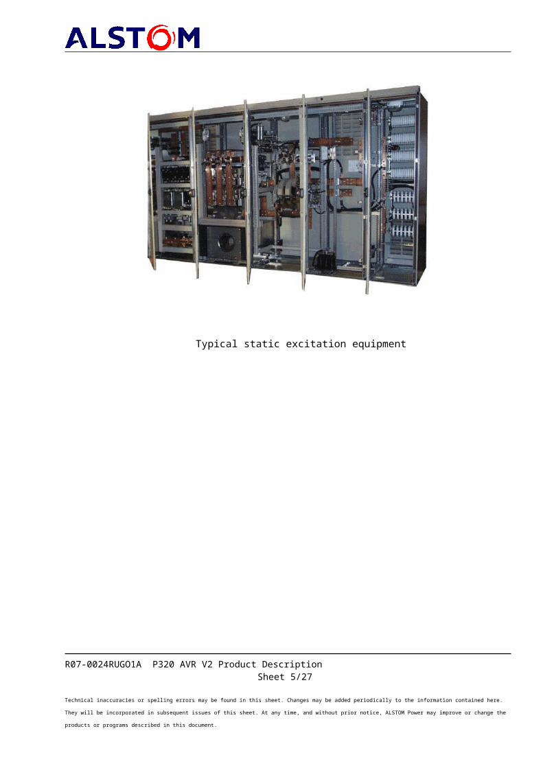
Typical static excitation equipment
R07-0024RUGO1A P320 AVR V2 Product DescriptionSheet 4/24
Technical inaccuracies or spelling errors may be found in this sheet. Changes may be added periodically to the information contained here. They will be incorporated in subsequent issues of this sheet. At any time, and without prior notice, ALSTOM Power may improve or change the products or programs described in this document.
2 DESCRIPTIONThe here below description gives the main possibilities of the P320 AVR; the application to each specific project is described in the excitation description
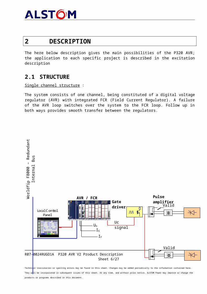
2.1 STRUCTURESingle channel structure :
The system consists of one channel, being constituted of a digital voltage regulator (AVR) with integrated FCR (Field Current Regulator). A failure of the AVR loop switches over the system to the FCR loop. Follow up in both ways provides smooth transfer between the regulators.
R07-0024RUGO1A P320 AVR V2 Product DescriptionSheet 5/24
Technical inaccuracies or spelling errors may be found in this sheet. Changes may be added periodically to the information contained here. They will be incorporated in subsequent issues of this sheet. At any time, and without prior notice, ALSTOM Power may improve or change the products or programs described in this document.
UGIGIF
Gate driver
AVR / FCR N°1 Valid
Uc signal
Wor
ldfip
F80
00 –
Redu
ndan
t Int
erna
l Bu
s
Valid
Pulse amplifier
Local Control Panel
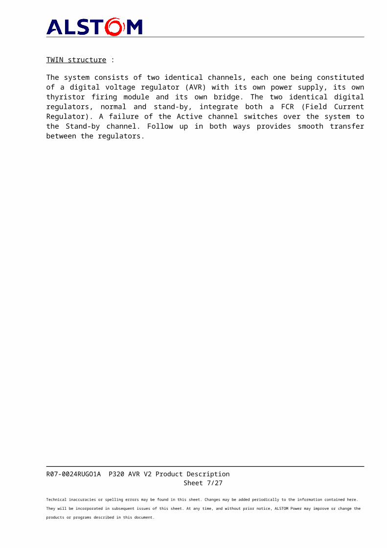
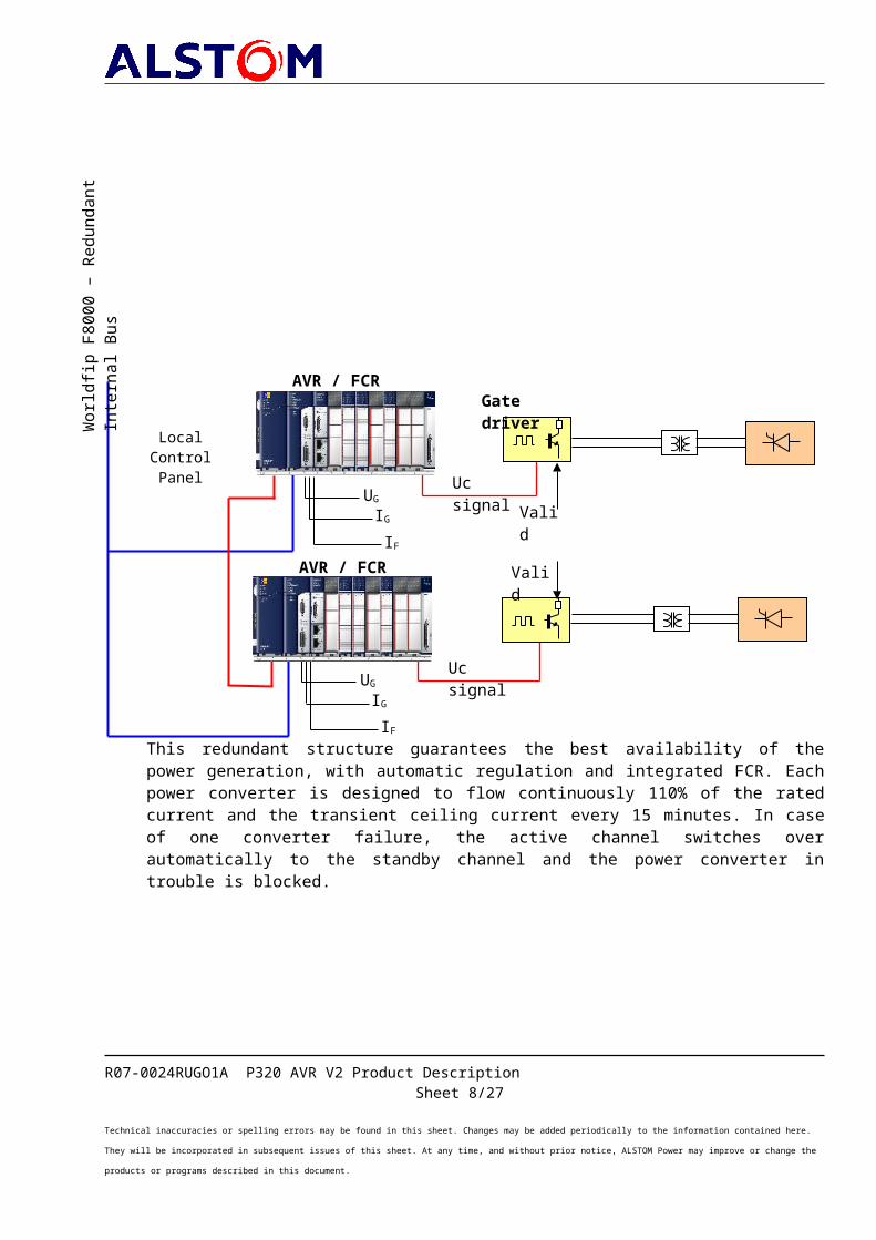
TWIN structure :
The system consists of two identical channels, each one being constituted of a digital voltage regulator (AVR) with its own power supply, its own thyristor firing module and its own bridge. The two identical digital regulators, normal and stand-by, integrate both a FCR (Field Current Regulator). A failure of the Active channel switches over the system to the Stand-by channel. Follow up in both ways provides smooth transfer between the regulators.
This redundant structure guarantees the best availability of the power generation, with automatic regulation and integrated FCR. Each power converter is designed to flow continuously 110% of the rated current and the transient ceiling current every 15 minutes. In case of one converter failure, the active channel switches over automatically to the standby channel and the power converter in trouble is blocked.
R07-0024RUGO1A P320 AVR V2 Product DescriptionSheet 6/24
Technical inaccuracies or spelling errors may be found in this sheet. Changes may be added periodically to the information contained here. They will be incorporated in subsequent issues of this sheet. At any time, and without prior notice, ALSTOM Power may improve or change the products or programs described in this document.
UGIGIF
Gate driver
Uc signal
AVR / FCR N°1
Valid
AVR / FCR N°2
Valid
Uc signal
Wor
ldfip
F80
00 –
Redu
ndan
t Int
erna
l Bu
s
Local ControlPanel
UGIGIF
R07-0024RUGO1A P320 AVR V2 Product DescriptionSheet 7/24
Technical inaccuracies or spelling errors may be found in this sheet. Changes may be added periodically to the information contained here. They will be incorporated in subsequent issues of this sheet. At any time, and without prior notice, ALSTOM Power may improve or change the products or programs described in this document.
Full redundant TWIN structure :
The system consists of two identical channels, each one being constituted of a digital voltage regulator (AVR) with its own power supply, its own thyristor firing module. The two identical digital regulators, normal and stand-by, integrate both a FCR (Field Current Regulator). A failure of the Active channel switches over the system to the Stand-by channel. Follow up in both ways provides smooth transfer between the regulators.
This redundant structure guarantees the best availability of the power generation, with automatic regulation and integrated FCR and thyristor bridge redundancy.
R07-0024RUGO1A P320 AVR V2 Product DescriptionSheet 8/24
Technical inaccuracies or spelling errors may be found in this sheet. Changes may be added periodically to the information contained here. They will be incorporated in subsequent issues of this sheet. At any time, and without prior notice, ALSTOM Power may improve or change the products or programs described in this document.
UGIGIF
Gate driver
Uc signal
AVR / FCR N°1
Valid
AVR / FCR N°2
Valid
Valid
Uc signal
Wor
ldfip
F80
00 –
Redu
ndan
t Int
erna
l Bu
s
Valid
Local ControlPanel
UGIGIF
Pulse amplifier
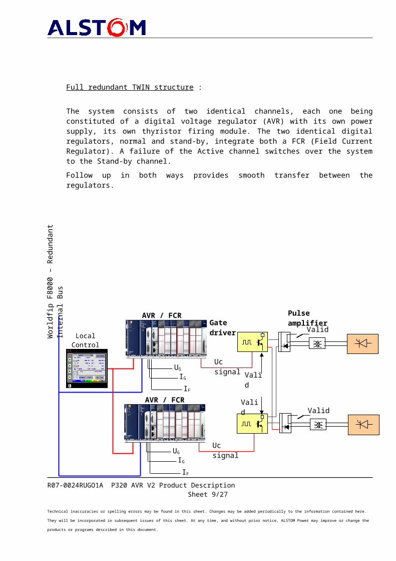
Each power converter is designed to flow continuously 110% of the rated current and the transient ceiling current every 15 minutes. Each power converter has got its own pulse amplifier with a pulse fault detection function, one power converter only being in operation. Each power converter can be controlled by neither of the regulator, ensuring a full redundancy. A failure on the active power converter will train over a changeover on the standby power converter with a smooth transfer by pulses overlapping through their pulse amplifier card. Power converter in trouble is blocked.
R07-0024RUGO1A P320 AVR V2 Product DescriptionSheet 9/24
Technical inaccuracies or spelling errors may be found in this sheet. Changes may be added periodically to the information contained here. They will be incorporated in subsequent issues of this sheet. At any time, and without prior notice, ALSTOM Power may improve or change the products or programs described in this document.
3 REGULATOR HARDWARE DESCRIPTION
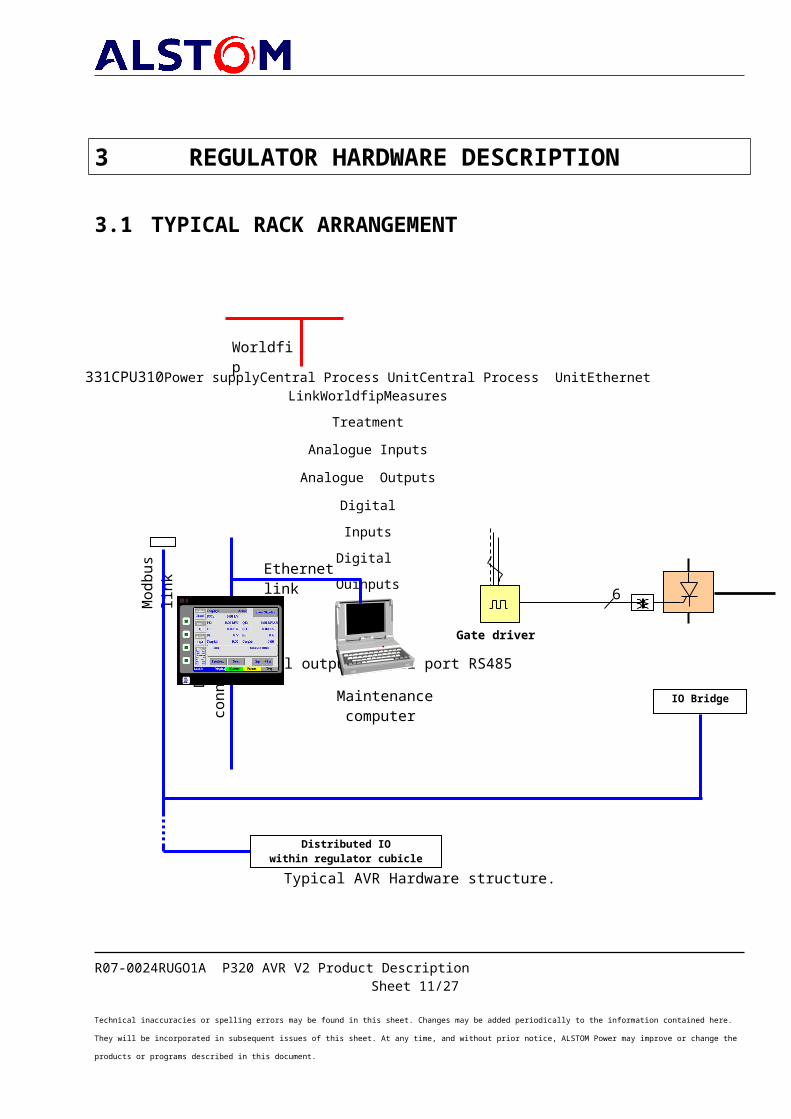
3.1 TYPICAL RACK ARRANGEMENT
Typical AVR Hardware structure.
R07-0024RUGO1A P320 AVR V2 Product DescriptionSheet 10/24
Technical inaccuracies or spelling errors may be found in this sheet. Changes may be added periodically to the information contained here. They will be incorporated in subsequent issues of this sheet. At any time, and without prior notice, ALSTOM Power may improve or change the products or programs described in this document.
Maintenance computer
Worldfip
Mod
bus l
ink
Gate driver
331CPU310Power supplyCentral Process UnitCentral Process UnitEthernet LinkWorldfipMeasures
TreatmentAnalogue Inputs
Analogue OutputsDigitalInputsDigital
Ouinputs
8Digital outputsSerial port RS485
6
IO Bridge
Distributed IOwithin regulator cubicle
Ethernet link
DCS
conn
ectio
n
3.2 POWER SUPPLYFeeder redundancy is performed by a double auxiliary source, one from the plant DC battery and the other from the excitation transformer secondary.
3.3 CENTRAL PROCESS UNITThe CPU has a Pentium III microprocessor with a 300 MHz clock. The user program capacity is typically of 10 Megabytes of RAM memory.
3.4 COMMUNICATION CAPABILITIESThe P320 AVR regulator offers wide communication capabilities, through its different port of communication :- the Ethernet board used to connect the DCS and the Local Control Panel. The
communication with the DCS is based on a non redundant copper link with Modbus TCP protocol,
- the central processing unit includes two serial ports, supporting Break-free SNP slave, Serial Read/Write and Modbus Slave protocol,
possible communication links- single RS485 copper serial link with Modbus protocol for connection with a DCS,
- redundant RS485 copper serial link with Modbus protocol for connection with a DCS,
- single RS485 optical fibre serial link with Modbus protocol for connection with a DCS,
- redundant RS485 optical fibre serial link with Modbus protocol for connection with a DCS,
- redundant Ethernet copper link with Modbus TCP protocol for connection with a DCS,
- single Ethernet optical fibre link with Modbus TCP protocol for connection with a DCS,
- redundant Ethernet optical fibre link with Modbus TCP protocol for connection with a DCS,
- the Worldfip interface for complete integration into P320 system.
The complete command, maintenance may be achieved through these communication links.
R07-0024RUGO1A P320 AVR V2 Product DescriptionSheet 11/24
Technical inaccuracies or spelling errors may be found in this sheet. Changes may be added periodically to the information contained here. They will be incorporated in subsequent issues of this sheet. At any time, and without prior notice, ALSTOM Power may improve or change the products or programs described in this document.
3.5 EXTERNAL INPUTS/OUTPUTSThe P320 AVR offers different type of inputs and outputs (analogue and digital) for logical and regulation sequences.For regulation, a dedicated card is performing from the generator measurement the following calculation :- the three individual line to line Voltages,
- the three individual line Currents,
- r.m.s. Stator Voltage,
- r.m.s. Stator Current,
- active Power,
- reactive Power,
- PSS2A or 2B corrective term,
- frequency,
- current and voltage status measurement monitoring.
An internal bus (RS485) is used within the excitation cubicle to issue and gather the main information for control and maintenance of the excitation equipment.Logic Inputs :
The logic inputs are polarised by the internal 24 Vdc generated in the excitation control cubicle. They are insulated by optic couplers. Light-emitting diodes indicate the status of each input.Four logic inputs are provided for controlling the excitation equipment (Excitation raise and lower command, unit breaker position).Logic Outputs :
The logic outputs are potential free. The outputs are isolated for external use with interposing relays.Four logic outputs are provided for external indication (Alarm, Trip, …).
R07-0024RUGO1A P320 AVR V2 Product DescriptionSheet 12/24
Technical inaccuracies or spelling errors may be found in this sheet. Changes may be added periodically to the information contained here. They will be incorporated in subsequent issues of this sheet. At any time, and without prior notice, ALSTOM Power may improve or change the products or programs described in this document.
3.6 GATE DRIVEREach regulator has its dedicated gate driver. This module receives the output signal (Uc) sent by the P320 AVR, elaborates and amplifies the firing pulses for the thyristors.
R07-0024RUGO1A P320 AVR V2 Product DescriptionSheet 13/24
Technical inaccuracies or spelling errors may be found in this sheet. Changes may be added periodically to the information contained here. They will be incorporated in subsequent issues of this sheet. At any time, and without prior notice, ALSTOM Power may improve or change the products or programs described in this document.
4 FUNCTIONS PERFORMED BY THE P320 AVR REGULATOR
The following function are performed voltage control including Power System Stabiliser (PSS2A or 2B type according IEEE
Std 421-5), current control in manual mode (maintenance, failure modes or specific start-
up), automatic voltage built up with progressive voltage raise (soft start), excitation current limitations : ceiling limitation, permanent current limitation
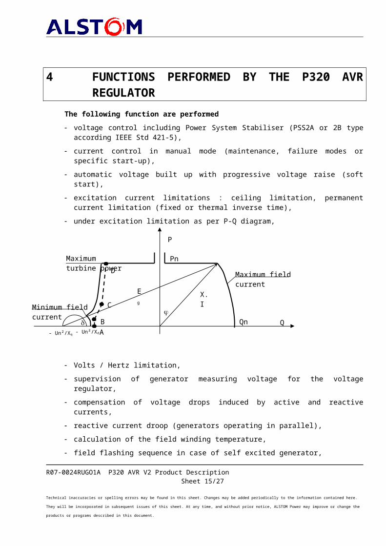
(fixed or thermal inverse time), under excitation limitation as per P-Q diagram,
Volts / Hertz limitation, supervision of generator measuring voltage for the voltage regulator, compensation of voltage drops induced by active and reactive currents, reactive current droop (generators operating in parallel), calculation of the field winding temperature, field flashing sequence in case of self excited generator, local information through a digital control panel connected to the regulator,
including detailed alarms and P-Q diagram display, excitation logic sequences, (field breaker control, bridge control, start, stop), communication with another control system through an Ethernet link (Modbus®
TCP).
R07-0024RUGO1A P320 AVR V2 Product DescriptionSheet 14/24
Technical inaccuracies or spelling errors may be found in this sheet. Changes may be added periodically to the information contained here. They will be incorporated in subsequent issues of this sheet. At any time, and without prior notice, ALSTOM Power may improve or change the products or programs described in this document.
P
Q
- Un²/Xq - Un²/Xd
Eg
X.I
Maximum turbine power
Minimum field current
Maximum field current
AB
C
D
Qn
Pn
The following functions can be supplied according generator needs:(Refer to relevant project technical description for the implemented optional functions)
stator current limitation (Two slopes), Line charging sequence (hydro projects), reactive Power or Power factor superimposed control, internal over current protection, excitation management to save field breaker operation number, specific motor starting sequences (Static Frequency Converter, Back to back
starting), specific shut down sequences (Electrical braking by short circuit or static
frequency converter), voltage matching sequence before synchronising, communication with another control system through a serial SNP link or serial
Modbus® link.
R07-0024RUGO1A P320 AVR V2 Product DescriptionSheet 15/24
Technical inaccuracies or spelling errors may be found in this sheet. Changes may be added periodically to the information contained here. They will be incorporated in subsequent issues of this sheet. At any time, and without prior notice, ALSTOM Power may improve or change the products or programs described in this document.
5 COMMISSIONING & MAINTENANCE TOOLS
5.1 LOCAL CONTROL PANELThe regulator is supplied with a user friendly defined Local Control Panel (LCP).
This graphical co loured touch screen terminal is installed in the front door of the excitation cubicle.
The display are available in four languages : English, French, German and Spanish.
Different levels of access are available :- display level,- operator level (Local commands ),- maintenance level (Local commands and
parameters setting).
The Local Control Panel, allows for the main excitation control and display (Field breaker command and status, AUTO/Manu mode change-over commands and status, Voltage/Reactive Power/Tan Phi control selection and status, excitation raise or lower commands …).It also displays the main measured and regulated values.
R07-0024RUGO1A P320 AVR V2 Product DescriptionSheet 16/24
Technical inaccuracies or spelling errors may be found in this sheet. Changes may be added periodically to the information contained here. They will be incorporated in subsequent issues of this sheet. At any time, and without prior notice, ALSTOM Power may improve or change the products or programs described in this document.
Gate drivermodule
The Local Control Panel may also help in operation of the generator with the dynamic display of the P-Q diagram :
To help maintenance of the excitation system, following information is available within the Local Control Panel :- current alarms. The current faults are also available on Modbus link and
Worldfip,- history of the different alarms,- maintenance overview with status of different regulators and links.
During commissioning, all the regulator parameters can be configured through the Local Control Panel.- A single software (ControCad Loader) fully installed in a PC (Note Book or
station) is recommended for easy maintenance.After the connection to the AVR, all parameters are accessible for display and setting.
R07-0024RUGO1A P320 AVR V2 Product DescriptionSheet 17/24
Technical inaccuracies or spelling errors may be found in this sheet. Changes may be added periodically to the information contained here. They will be incorporated in subsequent issues of this sheet. At any time, and without prior notice, ALSTOM Power may improve or change the products or programs described in this document.

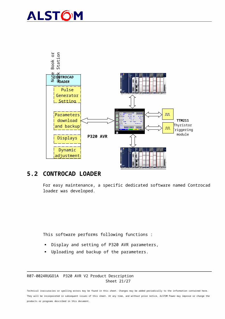
5.2 CONTROCAD LOADER For easy maintenance, a specific dedicated software named Controcad loader was developed.
This software performs following functions :
Display and setting of P320 AVR parameters, Uploading and backup of the parameters.
R07-0024RUGO1A P320 AVR V2 Product DescriptionSheet 18/24
Technical inaccuracies or spelling errors may be found in this sheet. Changes may be added periodically to the information contained here. They will be incorporated in subsequent issues of this sheet. At any time, and without prior notice, ALSTOM Power may improve or change the products or programs described in this document.
Dynamic adjustments
Displays
Parameters download
and backup
Pulse Generator
Setting
TTM211Thyristor
Triggering module
CONTROCADlOADER
P320 AVR
Note
Boo
k or
W
ork
Stat
ion

on-line Display and Diagnostics,
specific display screens for curves of any internal P320 AVR variable,
R07-0024RUGO1A P320 AVR V2 Product DescriptionSheet 19/24
Technical inaccuracies or spelling errors may be found in this sheet. Changes may be added periodically to the information contained here. They will be incorporated in subsequent issues of this sheet. At any time, and without prior notice, ALSTOM Power may improve or change the products or programs described in this document.
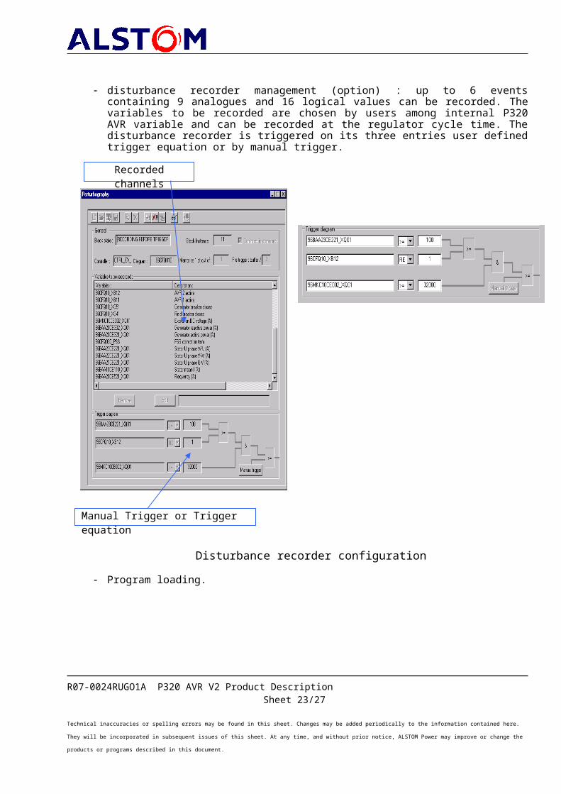
disturbance recorder management (option) : up to 6 events containing 9 analogues and 16 logical values can be recorded. The variables to be recorded are chosen by users among internal P320 AVR variable and can be recorded at the regulator cycle time. The disturbance recorder is triggered on its three entries user defined trigger equation or by manual trigger.
Disturbance recorder configuration Program loading.
R07-0024RUGO1A P320 AVR V2 Product DescriptionSheet 20/24
Technical inaccuracies or spelling errors may be found in this sheet. Changes may be added periodically to the information contained here. They will be incorporated in subsequent issues of this sheet. At any time, and without prior notice, ALSTOM Power may improve or change the products or programs described in this document.
Recorded channels
Manual Trigger or Trigger equation
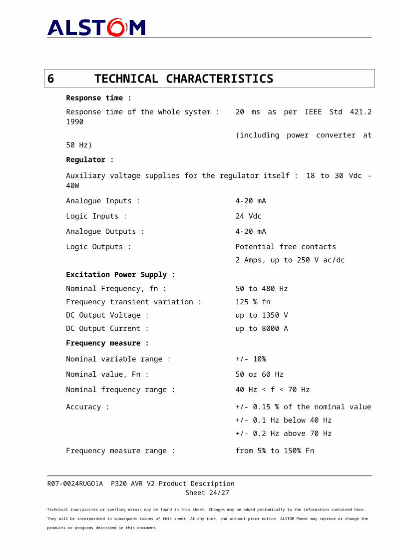
6 TECHNICAL CHARACTERISTICSResponse time :Response time of the whole system : 20 ms as per IEEE Std 421.2 1990
(including power converter at 50 Hz)Regulator :Auxiliary voltage supplies for the regulator itself : 18 to 30 Vdc – 40WAnalogue Inputs : 4-20 mALogic Inputs : 24 VdcAnalogue Outputs : 4-20 mALogic Outputs : Potential free contacts
2 Amps, up to 250 V ac/dcExcitation Power Supply :Nominal Frequency, fn : 50 to 480 HzFrequency transient variation : 125 % fnDC Output Voltage : up to 1350 VDC Output Current : up to 8000 AFrequency measure :Nominal variable range : +/- 10%Nominal value, Fn : 50 or 60 HzNominal frequency range : 40 Hz < f < 70 Hz
Accuracy : +/- 0.15 % of the nominal value+/- 0.1 Hz below 40 Hz+/- 0.2 Hz above 70 Hz
Frequency measure range : from 5% to 150% Fn
R07-0024RUGO1A P320 AVR V2 Product DescriptionSheet 21/24
Technical inaccuracies or spelling errors may be found in this sheet. Changes may be added periodically to the information contained here. They will be incorporated in subsequent issues of this sheet. At any time, and without prior notice, ALSTOM Power may improve or change the products or programs described in this document.

Voltage Measure :Stator nominal voltage measure, Un : 3 x 100 to 120 VacAccuracy : 0.15 % Un in the range 40 … 70 HzValidity range : 0 to 150 % Un, up to 90 Hz.Maximum steady state value : 110 % UnMaximum repetitive value : 150 % UnMaximum occasional value : 250 % Un
Current Measure :Stator nominal current measure, In : 3 x 1 or 5 AmpsAccuracy : 0.15 % Un in the range 40 … 70 HzValidity range : 0 to 200 % In, up to 90 Hz.Maximum steady state value : 110 % InMaximum occasional value : 500 % In
R07-0024RUGO1A P320 AVR V2 Product DescriptionSheet 22/24
Technical inaccuracies or spelling errors may be found in this sheet. Changes may be added periodically to the information contained here. They will be incorporated in subsequent issues of this sheet. At any time, and without prior notice, ALSTOM Power may improve or change the products or programs described in this document.
CertificationÁÁÁÁÁÁÁÁÁÁÁÁÁÁÁÁÁÁÁÁÁÁÁÁÁÁÁÁÁÁ
ÁÁÁÁÁÁÁÁÁÁQuality Assurance in Design/Development, Production, Installation and Servicing
ISO9001 Certification by Lloyd’s Register QualityAssurance
European EMC and Low Voltage Directives ÁÁÁÁ
CE Mark ÁÁ Certification by Competent Body for EMC Directive for selected modules
Safety for Industrial Control Equipment
UL508
C-UL orCSA22.2,142-M1987
Certification by Underwriters Laboratories Certification by Underwriters Laboratories [C-UL1] or Canadian Standards Association for selected C80–35 module
Safety for Hazardous Locations Class I, Zone 2, A, B, C, D
UL1604with C–UL
Certification by Underwriters Laboratories for selected modules Alspa C80–35
EnvironmentEnvironmentalVibration IEC60068–2–6 1g at 57-150 Hz, 5 microns
(0.012 in) p-p at 10-57 HzShock IEC60068–2–27 15 g, 11 msOperating Temperature
0 to 60°C (32 to 140°F) inside P320 cubicle0 to 45°C (32 to 113°F) outside P320 cubicle
Storage Temperature Á – 40°C to + 85°C (–40°F to +185°F)Humidity 5 to 95 % non-condensingEnclosure Protection IEC 529
NEMA 250Steel cabinet per IP325NEMA2
EMC Emissions EN50081-2Radiated, Conducted CISPR 11/EN
55011CISPR 22/EN 55022
47 CFR 15
Industrial Scientific & Medical Equipment (Group 1, Class A)Information Technology Equipment (Class A)
referred to as FCC part 15, “Radio Devices” (Class A)
EMC Immunity EN50082-2 (applies to CE Marked modules)
Electrostatic Discharge EN 61000–4–2 8 kV Air, 4 kV Contact (6 kV Contact with FIP Controller)
RF susceptibility EN 61000–4–3 10 Vrms/m, 80 to 1000 MHz, 80% AMFast Transient Burst EN 61000–4–4 2 kV : power supplies and FIP Controller, 1kV : I/O
and othercommunication lines
Damped Oscillatory Wave ANSI/IEEE C37.90a
IEC255–4
Damped Oscillatory Wave 1MHz, rep. Rate 400Hz : 2.5 kV (CM & DM) power supplies,2.5 kV (CM) I/O (12 V–240 V)
Damped Oscillatory Wave : class IIpower supplies, I/O (12 V–240 V)
Voltage Surge EN 61000–4–5 2 kV power supplies ; 1 kV cm (I/O)2 kV (FIP BIU) (all level for common mode)
Conducted RF EN 61000–4–6 10Vrms, 150 kHz to 80 MHz, 80% AMÁ IsolationDielectric Withstand IEC 664
UL508, UL8401.5 kV for modules rated from 51V to 250 V
Power SupplyR07-0024RUGO1A P320 AVR V2 Product Description
Sheet 23/24Technical inaccuracies or spelling errors may be found in this sheet. Changes may be added periodically to the information contained here. They will be incorporated in subsequent issues of this sheet. At any time, and without prior notice, ALSTOM Power may improve or change the products or programs described in this document.
Voltage Dips, Variations EN 61000–4–11 During Operation : Dips to 30% and 100% (100ms)Variation for AC=10%, Variation for DC=20%
ÁÁÁÁÁÁÁÁÁÁÁÁÁÁ
R07-0024RUGO1A P320 AVR V2 Product DescriptionSheet 24/24
Technical inaccuracies or spelling errors may be found in this sheet. Changes may be added periodically to the information contained here. They will be incorporated in subsequent issues of this sheet. At any time, and without prior notice, ALSTOM Power may improve or change the products or programs described in this document.