p100 eom - wilden pumps · wilden pump & engineering, llc 2 wil-11050-e-02 section 2 ® the...
TRANSCRIPT

P100
WIL-11050-E-02
EOM
A d v a n c e y o u r p r o c e s s
E n g i n e e r i n g O p e r a t i o n &M a i n t e n a n c eAdvanced™ Series PLASTIC Pumps
SECTION 1 CAUTIONS – READ FIRST! . . . . . . . . . . . . . . . . . . . . . . . . . . . . . . . . . . . . . . . . . . . . .1
SECTION 2 PUMP DESIGNATION SYSTEM . . . . . . . . . . . . . . . . . . . . . . . . . . . . . . . . . . . . . . . . .2
SECTION 3 HOW IT WORKS (PUMP & AIR SYSTEMS) . . . . . . . . . . . . . . . . . . . . . . . . . . . . . .3
SECTION 4 DIMENSIONAL DRAWINGA. P100 ADVANCED™ PLASTIC . . . . . . . . . . . . . . . . . . . . . . . . . . . . . . . . . . . . . . . . . . . . .4
SECTION 5 PERFORMANCE CURVESA. P100 ADVANCED™ PLASTIC Rubber-Fitted . . . . . . . . . . . . . . . . . . . . . . . . . . . . . . . . .5
B. P100 ADVANCED™ PLASTIC TPE-Fitted . . . . . . . . . . . . . . . . . . . . . . . . . . . . . . . . . . . . .5
C. P100 ADVANCED™ PLASTIC PTFE-Fitted . . . . . . . . . . . . . . . . . . . . . . . . . . . . . . . . . . .6
SECTION 6 SUCTION LIFT CURVES & DATA . . . . . . . . . . . . . . . . . . . . . . . . . . . . . . . . . . . . . . . . .6
SECTION 7 INSTALLATION AND OPERATIONA. Installation . . . . . . . . . . . . . . . . . . . . . . . . . . . . . . . . . . . . . . . . . . . . . . . . . . . . . . . . . . . .7
B. Operation & Maintenance . . . . . . . . . . . . . . . . . . . . . . . . . . . . . . . . . . . . . . . . . . . . . . . .8
C. Troubleshooting . . . . . . . . . . . . . . . . . . . . . . . . . . . . . . . . . . . . . . . . . . . . . . . . . . . . . . . .9
SECTION 8 DIRECTIONS FOR DISASSEMBLY/REASSEMBLYA. P100 ADVANCED™ PLASTIC Wetted – Tools Required, Cautions . . . . . . . . . . . . . . . 10
B. Pro-Flo® Air Valve/Center Block – Disassembly, Cleaning, Inspection . . . . . . . . . . . .13
C. Reassembly Hints & Tips, Torque Specifications . . . . . . . . . . . . . . . . . . . . . . . . . . . .15
SECTION 9 EXPLODED VIEW/PARTS LISTINGA. P100 ADVANCED™ PLASTIC Rubber/TPE-Fitted . . . . . . . . . . . . . . . . . . . . . . . . . . . .16
B. P100 ADVANCED™ PLASTIC PTFE-Fitted . . . . . . . . . . . . . . . . . . . . . . . . . . . . . . . . . .18
SECTION 10 ELASTOMER OPTIONS . . . . . . . . . . . . . . . . . . . . . . . . . . . . . . . . . . . . . . . . . . . . . . . .20
Cla
ss
I &II Ozone
Depleting Substanc
esNON
USEU.S. Clean Air Act
Amendments of 1990
®
T A B L E O F C O N T E N T S
WIL-11050-E-02 1 WILDEN PUMP & ENGINEERING, LLC
TEMPERATURE LIMITS*
Wetted Path Polypropylene (PP) 0°C to 79.4°C 32°F to 175°F Polyvinylidene fluoride (PVDF) -12.2°C to 107.2°C 10°F to 225°F
Elastomers Neoprene -17.8°C to 93.3°C 0°F to 200°F Buna-N -12.2°C to 82.2°C 10°F to 180°F Viton® -40°C to 176.7°C -40°F to 350°F Wil-Flex™ -40°C to 107.2°C -40°F to 225°F Polyurethane 12.2°C to 65.6°C 10°F to 150°F Polytetrafluoroethylene (PTFE) 4.4°C to 104.4°C 40°F to 220°F
Saniflex™ -28.9°C to 104.4°C -20°F to 220°F
*Elastomer choice may change temperature limits
CAUTION: When choosing pump materials, be sure to check the temperature limits for all wetted compo-nents. Example: Viton® has a maximum limit of 176.7°C (350°F) but polypropylene has a maximum limit of only 79.4°C (175°F).
CAUTION: Maximum temperature limits are based upon mechanical stress only. Certain chemicals will significantly reduce maximum safe operating tempera-tures. Consult engineering guide for chemical compat-ibility and temperature limits.
CAUTION: Always wear safety glasses when operat-ing pump. If diaphragm rupture occurs, material being pumped may be forced out air exhaust.
WARNING: Prevention of static sparking — If static sparking occurs, fire or explosion could result. Proper grounding of pump, valves, and containers is critical when handling flammable fluids or whenever discharge of static electricity is a hazard.
CAUTION: Do not exceed 8.6 bar (125 psig) air supply pressure.
CAUTION: Advanced™ series plastic pumps are made with plastic that is not UV stabilized. Direct sunlight for prolonged periods can cause deterioration of plastics.
CAUTION: Before any maintenance or repair is attempted, the compressed air line to the pump should be disconnected and all air pressure allowed to bleed from pump. Disconnect all intake, discharge and air lines. Drain the pump by turning it upside down and allowing any fluid to flow into a suitable container.
CAUTION: Blow out air line for 10 to 20 seconds before attaching to pump to make sure all pipe line debris is clear. Use an in-line air filter. A 5µ (micron) air filter is recommended.
NOTE: Tighten all bolts prior to installation. Fasteners may loosen during transportation. See torque specifi-cations on page 15.
NOTE: When installing polytetrafluoroethylene (PTFE) dia-phragms, it is important to tighten outer pistons simultane-ously (turning in opposite directions) to ensure tight fit.
CAUTION: Verify the chemical compatibility of the process and cleaning fluid to the pump’s component materials in the Chemical Resistance Guide (see E4).
CAUTION:When removing the end cap using compressed air, the air valve end cap may come out with considerable force. Hand protection such as a padded glove or rag should be used to capture the end cap.
CAUTION: Do not over-tighten the air inlet reducer bushing. Additionally, too much torque on the muffler may damage the air valve muffler plate.
S e c t i o n 1®
C A U T I O N S — R E A D F I R S T !

WILDEN PUMP & ENGINEERING, LLC 2 WIL-11050-E-02
S e c t i o n 2®
T H E W I L D E N P U M P D E S I G N A T I O N S Y S T E M
P100 ADVANCED™ PLASTIC13 mm (1/2") PumpMaximum Flow Rate:58.7 LPM (15.5 GPM)
MATERIAL CODES
WETTED PARTS & OUTER PISTONKK = PVDF / PVDFPP = POLYPROPYLENE /
POLYPROPYLENE
CENTER SECTIONPP = POLYPROPYLENE
AIR VALVEP = POLYPROPYLENE
DIAPHRAGMSBNS = BUNA-N (Red Dot)FSS = SANIFLEX™
[Hytrel® (Cream)]PUS = POLYURETHANE (Clear)THU = PTFE W/HI-TEMP
BUNA-N BACK-UP (White)TNL = PTFE W/NEOPRENE
BACK-UP O-RING, IPD (White)
TNU = PTFE W/NEOPRENE BACK-UP (White)
VTS = VITON® (White Dot)WFS = WIL-FLEX™ [Santoprene®
(Orange Dot)]
VALVE BALLBN = BUNA-N (Red Dot)FS = SANIFLEX™
[Hytrel® (Cream)]PU = POLYURETHANE (Brown)TF = PTFE (White)VT = VITON® (White Dot)WF = WIL-FLEX™ [Santoprene®
(Orange Dot)]
VALVE SEATK = PVDFP = POLYPROPYLENE
VALVE SEAT O-RINGBN = BUNA-N FS = SANIFLEX™
[Hytrel® (Cream)]PU = POLYURETHANE (Brown)TV = PTFE ENCAP. VITON®
WF = WIL-FLEX™ (Santoprene®)
LEGEND P100 / XXXXX / XXX / XX / XXX / XXXX
O-RINGSMODEL VALVE SEAT
VALVE BALLSDIAPHRAGMS
AIR VALVECENTER SECTION
WETTED PARTS & OUTER PISTON
SPECIALTYCODE(if applicable)
SPECIALTY CODES
0014 BSPT0102 Wil-Gard II™, sensor wires ONLY0677 Center ported, NPT (Parts Only)0678 Center ported, BSPT (Parts Only)0680 P100 with OEM specific inlet manifold0683 P100 with OEM specific inlet manifold, center
ported inlet and discharge manifolds, NPT0790 P100 Advanced, drum pump inlet manifold
NOTES: MOST ELASTOMERIC MATERIALS USE COLORED DOTS FOR IDENTIFICATION. Viton® is a registered trademark of DuPont Dow Elastomers.
WIL-11050-E-02 3 WILDEN PUMP & ENGINEERING, LLC
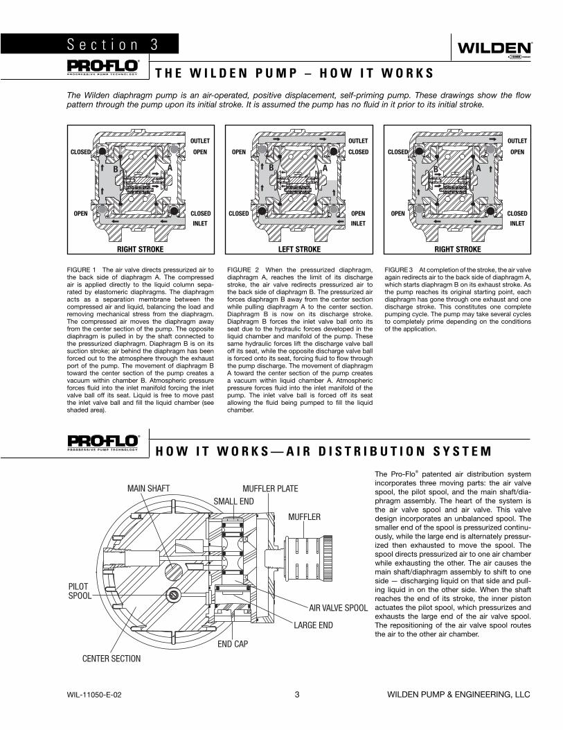
The Pro-Flo® patented air distribution system incorporates three moving parts: the air valve spool, the pilot spool, and the main shaft/dia-phragm assembly. The heart of the system is the air valve spool and air valve. This valve design incorporates an unbalanced spool. The smaller end of the spool is pressurized continu-ously, while the large end is alternately pressur-ized then exhausted to move the spool. The spool directs pressurized air to one air chamber while exhausting the other. The air causes the main shaft/diaphragm assembly to shift to one side — discharging liquid on that side and pull-ing liquid in on the other side. When the shaft reaches the end of its stroke, the inner piston actuates the pilot spool, which pressurizes and exhausts the large end of the air valve spool. The repositioning of the air valve spool routes the air to the other air chamber.
S e c t i o n 3®
T H E W I L D E N P U M P – H O W I T W O R K S
The Wilden diaphragm pump is an air-operated, positive displacement, self-priming pump. These drawings show the flow pattern through the pump upon its initial stroke. It is assumed the pump has no fluid in it prior to its initial stroke.
FIGURE 1 The air valve directs pressurized air to the back side of diaphragm A. The compressed air is applied directly to the liquid column sepa-rated by elastomeric diaphragms. The diaphragm acts as a separation membrane between the compressed air and liquid, balancing the load and removing mechanical stress from the diaphragm. The compressed air moves the diaphragm away from the center section of the pump. The opposite diaphragm is pulled in by the shaft connected to the pressurized diaphragm. Diaphragm B is on its suction stroke; air behind the diaphragm has been forced out to the atmosphere through the exhaust port of the pump. The movement of diaphragm B toward the center section of the pump creates a vacuum within chamber B. Atmospheric pressure forces fluid into the inlet manifold forcing the inlet valve ball off its seat. Liquid is free to move past the inlet valve ball and fill the liquid chamber (see shaded area).
FIGURE 2 When the pressurized diaphragm, diaphragm A, reaches the limit of its discharge stroke, the air valve redirects pressurized air to the back side of diaphragm B. The pressurized air forces diaphragm B away from the center section while pulling diaphragm A to the center section. Diaphragm B is now on its discharge stroke. Diaphragm B forces the inlet valve ball onto its seat due to the hydraulic forces developed in the liquid chamber and manifold of the pump. These same hydraulic forces lift the discharge valve ball off its seat, while the opposite discharge valve ball is forced onto its seat, forcing fluid to flow through the pump discharge. The movement of diaphragm A toward the center section of the pump creates a vacuum within liquid chamber A. Atmospheric pressure forces fluid into the inlet manifold of the pump. The inlet valve ball is forced off its seat allowing the fluid being pumped to fill the liquid chamber.
FIGURE 3 At completion of the stroke, the air valve again redirects air to the back side of diaphragm A, which starts diaphragm B on its exhaust stroke. As the pump reaches its original starting point, each diaphragm has gone through one exhaust and one discharge stroke. This constitutes one complete pumping cycle. The pump may take several cycles to completely prime depending on the conditions of the application.
RIGHT STROKE
CLOSED CLOSED OPENOPEN
OPEN OPEN CLOSED
OUTLET
INLET
OPEN
CLOSEDCLOSED
OUTLET
INLET
CLOSED
OPEN
OUTLET
INLET
LEFT STROKE RIGHT STROKE
®
H O W I T W O R K S — A I R D I S T R I B U T I O N S Y S T E M

WILDEN PUMP & ENGINEERING, LLC 4 WIL-11050-E-02
S e c t i o n 4 A®
D I M E N S I O N A L D R A W I N G
P100 Advanced™ Plastic
DIMENSIONS – P100 ADVANCED™ PLASTIC
ITEM METRIC (mm) STANDARD (inch)
A 234 9.2
B 51 2.0
C 170 6.7
D 254 10.0
E 277 10.9
F 25 1.0
G 114 4.5
H 201 7.9
J 170 6.7
K 145 5.7
L 114 4.5
M 102 4.0
N 91 3.6
P 8 0.3
KL
N M
P
13 mm (1/2")FNPT DIS-
CHARGE
D
A
C
E
F
G
H
J
B
13 mm (1/2")FNPT INLET
13 mm (1/2")FNPT AIR EXHAUST
6 mm (1/4")FNPT AIR INLET
B
R
S
TU
P
OEM FOOTPRINT DIMENSIONS
ITEM METRIC (mm) STANDARD (inch)
R 188 7.4
S 156 6.1
T 140 5.5
U 129 5.1
WIL-11050-E-02 5 WILDEN PUMP & ENGINEERING, LLC
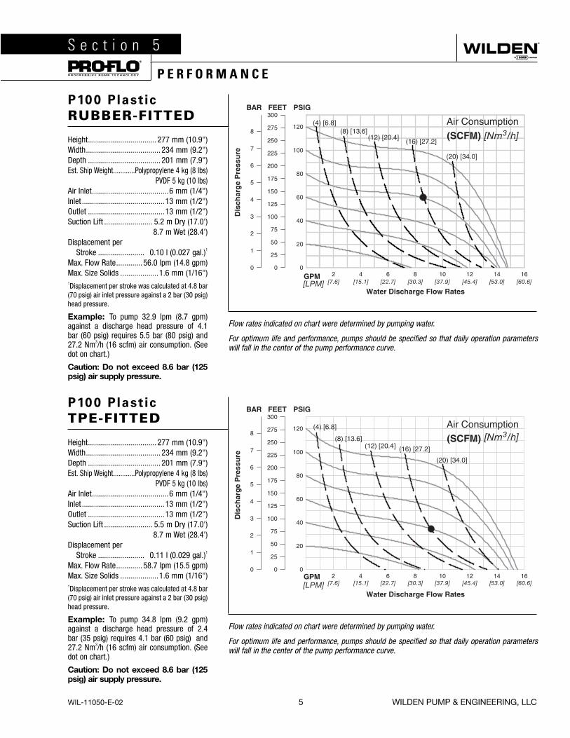
P100 Plastic
RUBBER-FITTED
Height .................................. 277 mm (10.9")Width ..................................... 234 mm (9.2") Depth .................................... 201 mm (7.9") Est. Ship Weight ............Polypropylene 4 kg (8 lbs)
PVDF 5 kg (10 lbs)Air Inlet ......................................6 mm (1/4")Inlet .........................................13 mm (1/2")Outlet ......................................13 mm (1/2")Suction Lift ........................ 5.2 m Dry (17.0')
8.7 m Wet (28.4')Displacement per Stroke ....................... 0.10 l (0.027 gal.)1
Max. Flow Rate ............. 56.0 lpm (14.8 gpm)Max. Size Solids ...................1.6 mm (1/16")1Displacement per stroke was calculated at 4.8 bar (70 psig) air inlet pressure against a 2 bar (30 psig) head pressure.
Example: To pump 32.9 lpm (8.7 gpm) against a discharge head pressure of 4.1 bar (60 psig) requires 5.5 bar (80 psig) and 27.2 Nm3/h (16 scfm) air consumption. (See dot on chart.)
Caution: Do not exceed 8.6 bar (125 psig) air supply pressure.
Flow rates indicated on chart were determined by pumping water.
For optimum life and performance, pumps should be specified so that daily operation parameters will fall in the center of the pump performance curve.
P100 Plastic
TPE-FITTED
Height .................................. 277 mm (10.9")Width ..................................... 234 mm (9.2") Depth .................................... 201 mm (7.9") Est. Ship Weight ............Polypropylene 4 kg (8 lbs)
PVDF 5 kg (10 lbs)Air Inlet ......................................6 mm (1/4")Inlet .........................................13 mm (1/2")Outlet ......................................13 mm (1/2")Suction Lift ........................ 5.5 m Dry (17.0')
8.7 m Wet (28.4')Displacement per Stroke ....................... 0.11 l (0.029 gal.)1
Max. Flow Rate ............. 58.7 lpm (15.5 gpm)Max. Size Solids ...................1.6 mm (1/16")1Displacement per stroke was calculated at 4.8 bar (70 psig) air inlet pressure against a 2 bar (30 psig) head pressure.
Example: To pump 34.8 lpm (9.2 gpm) against a discharge head pressure of 2.4 bar (35 psig) requires 4.1 bar (60 psig) and 27.2 Nm3/h (16 scfm) air consumption. (See dot on chart.)
Caution: Do not exceed 8.6 bar (125 psig) air supply pressure.
Flow rates indicated on chart were determined by pumping water.
For optimum life and performance, pumps should be specified so that daily operation parameters will fall in the center of the pump performance curve.
S e c t i o n 5®
P E R F O R M A N C E
WILDEN PUMP & ENGINEERING, LLC 6 WIL-11050-E-02
P100 Plastic
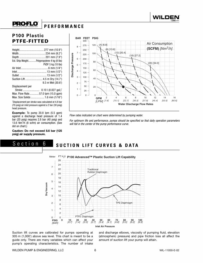
PTFE-FITTED
Height .................................. 277 mm (10.9")Width ..................................... 234 mm (9.2") Depth .................................... 201 mm (7.9") Est. Ship Weight ............Polypropylene 4 kg (8 lbs)
PVDF 5 kg (10 lbs)Air Inlet ......................................6 mm (1/4")Inlet .........................................13 mm (1/2")Outlet ......................................13 mm (1/2")Suction Lift ........................ 4.5 m Dry (14.7')
9.3 m Wet (30.6')Displacement per Stroke ....................... 0.10 l (0.027 gal.)1
Max. Flow Rate ............. 57.0 lpm (15.0 gpm)Max. Size Solids ...................1.6 mm (1/16")1Displacement per stroke was calculated at 4.8 bar (70 psig) air inlet pressure against a 2 bar (30 psig) head pressure.
Example: To pump 20.8 lpm (5.5 gpm) against a discharge head pressure of 1.4 bar (20 psig) requires 2.8 bar (40 psig) and 13.6 Nm3/h (8 scfm) air consumption. (See dot on chart.)
Caution: Do not exceed 8.6 bar (125 psig) air supply pressure.
Flow rates indicated on chart were determined by pumping water.
For optimum life and performance, pumps should be specified so that daily operation parameters will fall in the center of the pump performance curve.
S e c t i o n 6 S U C T I O N L I F T C U R V E S & D A T A
Suction lift curves are calibrated for pumps operating at 305 m (1,000') above sea level. This chart is meant to be a guide only. There are many variables which can affect your pump’s operating characteristics. The number of intake
and discharge elbows, viscosity of pumping fluid, elevation (atmospheric pressure) and pipe friction loss all affect the amount of suction lift your pump will attain.
®
P E R F O R M A N C E

WIL-11050-E-02 7 WILDEN PUMP & ENGINEERING, LLC
S e c t i o n 7 A®
I N S T A L L A T I O N
The Pro-Flo® model P100 Advanced™ plastic has a 13 mm (1/2") inlet and 13 mm (1/2") outlet and is designed for flows to 58.7 lpm (15.5 gpm). The P100 Advanced™ plastic pump is manufactured with wetted parts of pure, unpig-mented Polypropylene or PVDF. The P100 Advanced™plastic pump is constructed with a glass fiber filled PP center section. A variety of diaphragms and o-rings are available to satisfy temperature, chemical compatibility, abrasion, and flex concerns.
The suction pipe size should be at least 13 mm (1/2”) diam-eter or larger if highly viscous material is being pumped. The suction hose must be non-collapsible, reinforced type as the P100 Advanced™ plastic pump is capable of pulling a high vacuum. Discharge piping should be at least 13 mm (1/2”); larger diameter can be used to reduce friction losses. It is critical that all fittings and connections are airtight or a reduc-tion or loss of pump suction capability will result.
INSTALLATION: Months of careful planning, study, and selection efforts can result in unsatisfactory pump perfor-mance if installation details are left to chance.
Premature failure and long term dissatisfaction can be avoided if reasonable care is exercised throughout the instal-lation process.
LOCATION: Noise, safety, and other logistical factors usually dictate where equipment should be situated on the produc-tion floor. Multiple installations with conflicting requirements can result in congestion of utility areas, leaving few choices for additional pumps.
Within the framework of these and other existing condi-tions, every pump should be located in such a way that 6 key factors are balanced against each other to maximum advantage.
ACCESS: First, the location should be accessible. If it is easy to reach the pump, maintenance personnel will have an easier time carrying out routine inspections and adjustments. Should major repairs become necessary, ease of access can play a key role in speeding the repair process and reducing total downtime.
AIR SUPPLY: Every pump location should have an air line large enough to supply the volume of air necessary to achieve the desired pumping rate (see Section 5). Use air pressure up to a maximum of 8.6 bar (125 psig) depending on pumping requirements.
For best results, the pumps should use a 5µ (micron) air filter, needle valve and regulator. The use of an air filter before the pump will insure that the majority of any pipeline contami-nants will be eliminated.
SOLENOID OPERATION: When operation is controlled by a solenoid valve in the air line, three-way valves should be used, thus allowing trapped air to bleed off and improving pump performance. Pumping volume can be set by count-ing the number of strokes per minute and multiplying by displacement per stroke.
SOUND: Sound levels are reduced using the standard Wilden muffler. Other mufflers can be used, but usually reduce pump performance.
ELEVATION: Selecting a site that is well within the pump’s dynamic lift capability will assure that loss-of-prime trou-bles will be eliminated. In addition, pump efficiency can be adversely affected if proper attention is not given to site location.
PIPING: Final determination of the pump site should not be made until the piping problems of each possible loca-tion have been evaluated. The impact of current and future installations should be considered ahead of time to make sure that inadvertent restrictions are not created for any remaining sites.
The best choice possible will be a site involving the shortest and straightest hook-up of suction and discharge piping. Unnecessary elbows, bends, and fittings should be avoided. Pipe sizes should be selected to keep friction losses within practical limits. All piping should be supported independently of the pump. In addition, the piping should be aligned to avoid placing stresses on the pump fittings.
Flexible hose can be installed to aid in absorbing the forces created by the natural reciprocating action of the pump. If the pump is to be bolted down to a solid location, a mount-ing pad placed between the pump and the foundation will assist in minimizing pump vibration. Flexible connections between the pump and rigid piping will also assist in mini-mizing pump vibration. If quick-closing valves are installed at any point in the discharge system, or if pulsation within a system becomes a problem, a surge suppressor should be installed to protect the pump, piping and gauges from surges and water hammer.
The P100 Advanced™ plastic Pro-Flo® equipped pump can be installed in submersible applications only when both the wetted and non-wetted portions are compatible with the material being pumped. If the pump is to be used in a submersible application, a hose should be attached to the air and pilot spool exhaust ports of the pump. These should then be piped above the liquid level. The exhaust area for the pilot spool is designed to be tapped for a 1/8" NPT fitting.
When pumps are installed in applications involving flooded suction or suction head pressures, a gate valve should be installed in the suction line to permit closing of the line for pump service.
If the pump is to be used in a self-priming application, be sure that all connections are airtight and that the suction-lift is within the ability of the model. Note: Materials of construc-tion and elastomer material have an effect on suction lift parameters. Please consult Wilden distributors for specifics.
Pumps in service with a positive suction head are most effi-cient when inlet pressure is limited to 0.5–0.7 bar (7– 10 psig). Premature diaphragm failure may occur if positive suction is 10 psig and higher.
THE MODEL P100 ADVANCED™ PLASTIC WILL PASS 1.6 mm (1/16") SOLIDS. WHENEVER THE POSSIBILITY EXISTS THAT LARGER SOLID OBJECTS MAY BE SUCKED INTO THE PUMP, A STRAINER SHOULD BE USED ON THE SUCTION LINE.
CAUTION: DO NOT EXCEED 8.6 BAR (125 PSIG) AIR SUPPLY PRESSURE.

WILDEN PUMP & ENGINEERING, LLC 8 WIL-11050-E-02
S e c t i o n 7 B S U G G E S T E D O P E R A T I O N A N D M A I N T E N A N C E I N S T R U C T I O N S
®
OPERATION: Pump discharge rate can be controlled by limiting the volume and/or pressure of the air supply to the pump (preferred method). An air regulator is used to regu-late air pressure. A needle valve is used to regulate volume. Pump discharge rate can also be controlled by throttling the pump discharge by partially closing a valve in the discharge line of the pump. This action increases friction loss which reduces flow rate. This is useful when the need exists to control the pump from a remote location. When the pump discharge pressure equals or exceeds the air supply pres-sure, the pump will stop; no bypass or pressure relief valve is needed, and pump damage will not occur. The pump has reached a “deadhead” situation and can be restarted by reducing the fluid discharge pressure or increasing the air inlet pressure. The Wilden P100 pump runs solely on compressed air and does not generate heat, therefore your process fluid temperature will not be affected.
RECORDS: When service is required, a record should be made of all necessary repairs and replacements. Over a period of time, such records can become a valuable tool for predicting and preventing future maintenance problems and unscheduled downtime. In addition, accurate records make it possible to identify pumps that are poorly suited to their applications.
MAINTENANCE AND INSPECTIONS: Since each applica-tion is unique, maintenance schedules may be different for every pump. Frequency of use, line pressure, viscosity and abrasiveness of process fluid all affect the parts life of a Wilden pump. Periodic inspections have been found to offer the best means for preventing unscheduled pump downtime. Personnel familiar with the pump’s construction and service should be informed of any abnormalities that are detected during operation.
®
S U G G E S T E D I N S T A L L A T I O N
WIL-11050-E-02 9 WILDEN PUMP & ENGINEERING, LLC
S e c t i o n 7 C®
T R O U B L E S H O O T I N G
Pump will not run or runs slowly.1. Ensure that the air inlet pressure is at least 0.4 bar (5 psig)
above startup pressure and that the differential pressure (the difference between air inlet and liquid discharge pres-sures) is not less than 0.7 bar (10 psig).
2. Check air inlet filter for debris (see recommended instal-lation).
3. Check for extreme air leakage (blow by) which would indi-cate worn seals/bores in the air valve, pilot spool, main shaft.
4. Disassemble pump and check for obstructions in the air passageways or objects which would obstruct the move-ment of internal parts.
5. Check for sticking ball check valves. If material being pumped is not compatible with pump elastomers, swell-ing may occur. Replace ball check valves and seals with proper elastomers. In addition, valve balls become smaller as the wear. This may cause them to become stuck in the seats. In this case, replace balls and seats.
6. Check for broken inner piston, which will prevent the air valve spool from shifting.
7. Remove plug from pilot spool exhaust, check pilot spool exhaust for blockage.
Pump runs but little or no product flows.1. Check for pump cavitation; slow pump speed down to
allow thick material to flow into liquid chambers.2. Verify that vacuum required to lift liquid is not greater than
the vapor pressure of the material being pumped (cavita-tion).
3. Check for sticking ball check valves. If material being pumped is not compatible with pump elastomers, swell-ing may occur. Replace ball check valves and seals with proper elastomers. In addition, valve balls become smaller as the wear. This may cause them to become stuck in the seats. In this case, replace balls and seats.
Pump air valve freezes.1. Check for excessive moisture in compressed air. Install
either a dryer, or hot air generator for compressed air. Alternatively, a coalescing filter may be used to remove the water from the compressed air in some applications.
Air bubbles in pump discharge.1. Check for ruptured diaphragm.2. Check tightness of outer pistons.3. Check torque of bolts and integrity of o-rings and seals,
especially at intake manifold.4. Ensure pipe connections are airtight.
Product comes out air exhaust.1. Check for diaphragm rupture.2. Check tightness of outer pistons to shaft.
WILDEN PUMP & ENGINEERING, LLC 10 WIL-11050-E-02
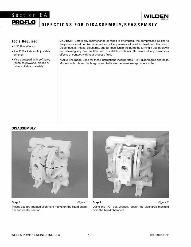
Tools Required:• 1/2" Box Wrench
• 2 – 1" Sockets or Adjustable Wrench
• Vise equipped with soft jaws (such as plywood, plastic or other suitable material)
CAUTION: Before any maintenance or repair is attempted, the compressed air line to the pump should be disconnected and all air pressure allowed to bleed from the pump. Disconnect all intake, discharge, and air lines. Drain the pump by turning it upside down and allowing any fluid to flow into a suitable container. Be aware of any hazardous effects of contact with your process fluid.
NOTE: The model used for these instructions incorporates PTFE diaphragms and balls. Models with rubber diaphragms and balls are the same except where noted.
Step 1. Figure 1
Please see pre-molded alignment marks on the liquid cham-ber and center section.
Step 2. Figure 2
Using the 1/2” box wrench, loosen the discharge manifold from the liquid chambers.
S e c t i o n 8 A®
D I R E C T I O N S F O R D I S A S S E M B L Y / R E A S S E M B L Y
DISASSEMBLY:
WIL-11050-E-02 11 WILDEN PUMP & ENGINEERING, LLC
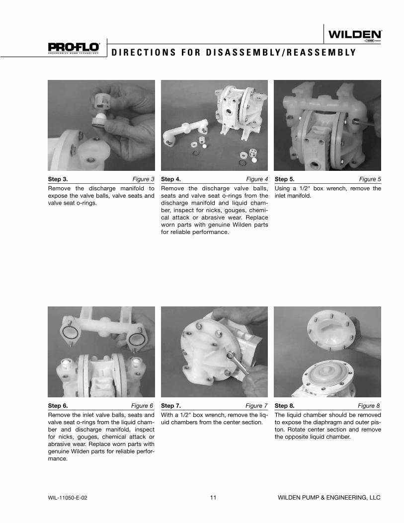
Step 6. Figure 6
Remove the inlet valve balls, seats and valve seat o-rings from the liquid cham-ber and discharge manifold, inspect for nicks, gouges, chemical attack or abrasive wear. Replace worn parts with genuine Wilden parts for reliable perfor-mance.
Step 7. Figure 7
With a 1/2" box wrench, remove the liq-uid chambers from the center section.
Step 8. Figure 8
The liquid chamber should be removed to expose the diaphragm and outer pis-ton. Rotate center section and remove the opposite liquid chamber.
5 A®
D I R E C T I O N S F O R D I S A S S E M B L Y / R E A S S E M B L Y
Step 3. Figure 3
Remove the discharge manifold to expose the valve balls, valve seats and valve seat o-rings.
Step 4. Figure 4
Remove the discharge valve balls, seats and valve seat o-rings from the discharge manifold and liquid cham-ber, inspect for nicks, gouges, chemi-cal attack or abrasive wear. Replace worn parts with genuine Wilden parts for reliable performance.
Step 5. Figure 5
Using a 1/2" box wrench, remove the inlet manifold.
WILDEN PUMP & ENGINEERING, LLC 12 WIL-11050-E-02
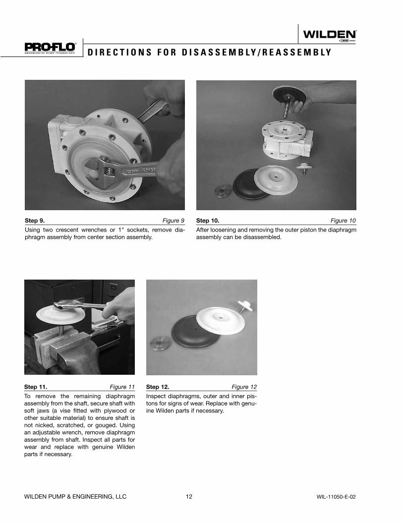
Step 9. Figure 9
Using two crescent wrenches or 1" sockets, remove dia-phragm assembly from center section assembly.
Step 10. Figure 10
After loosening and removing the outer piston the diaphragm assembly can be disassembled.
®
D I R E C T I O N S F O R D I S A S S E M B L Y / R E A S S E M B L Y
Step 11. Figure 11
To remove the remaining diaphragm assembly from the shaft, secure shaft with soft jaws (a vise fitted with plywood or other suitable material) to ensure shaft is not nicked, scratched, or gouged. Using an adjustable wrench, remove diaphragm assembly from shaft. Inspect all parts for wear and replace with genuine Wilden parts if necessary.
Step 12. Figure 12
Inspect diaphragms, outer and inner pis-tons for signs of wear. Replace with genu-ine Wilden parts if necessary.

WIL-11050-E-02 13 WILDEN PUMP & ENGINEERING, LLC
Tools Required:• 3/16" Allen Wrench
• Snap Ring Pliers
• O-Ring Pick
AIR VALVE DISASSEMBLY:
CAUTION: Before any maintenance or repair is attempted, the compressed air line to the pump should be disconnected and all air pressure allowed to bleed from the pump. Disconnect all intake, discharge, and air lines. Drain the pump by turning it upside down and allowing any fluid to flow into a suitable container. Be aware of hazardous effects of contact with your process fluid.
The Wilden P100 Advanced™ Plastic Pump utilizes a revolutionary Pro-Flo® air distribution system. A 6 mm (1/4") air inlet connects the air supply to the center section. Proprietary com-posite seals reduce the co efficient of friction and allow the P100 to run lube-free. Constructed of polypropylene, the Pro-Flo® air distribution system is designed to perform in on/off, non-freezing, non-stalling, tough duty applications.
Step 1. Figure 1
Loosen the air valve bolts utilizing a 3/16" Allen wrench.
Step 2. Figure 2
Remove muffler plate and air valve bolts from air valve assembly exposing muffler gasket for inspection. Replace if necessary.
Step 3. Figure 3
Lift away air valve assembly and remove air valve gasket for inspection . Replace if necessary.
S e c t i o n 8 B®
A IR VA LV E / CEN T ER BL OC K — REPA IR / M A IN T EN A NCE

WILDEN PUMP & ENGINEERING, LLC 14 WIL-11050-E-02
Step 7. Figure 7
Remove pilot spool sleeve from center section.
Step 8. Figure 8
With o-ring pick, gently remove the o-ring from the opposite side of the “center hole” cut on the spool. Gently remove the pilot spool from sleeve and inspect for nicks or gouges and other signs of wear. Replace pilot sleeve assembly or outer sleeve o-rings if necessary. During re-assembly never insert the pilot spool into the sleeve with the “center cut” side first, this end incorporates the urethane o-ring and will be damaged as it slides over the ports cut in the sleeve.
NOTE: Seals should not be removed from pilot spool. Seals are not sold separately.
Step 9. Figure 9
Check center section Glyd™ rings for signs of wear. If necessary, remove Glyd™ rings with o-ring pick and replace.
®
D I S A S S E M B L Y, C L E A N I N G , I N S P E C T I O N
Step 4. Figure 4
Remove air valve end cap to expose air valve spool by simply lifting up on end cap once air valve bolts are removed.
Step 5. Figure 5
Remove air valve spool from air valve body by threading one air valve bolt into the end of the spool and gently sliding the spool out of the air valve body. Inspect seals for signs of wear and replace entire assembly if necessary. Use caution when handling air valve spool to prevent damaging seals.
NOTE: Seals should not be removed from assembly. Seals are not sold separately.
Step 6. Figure 6
Remove pilot spool sleeve retaining snap ring on both sides of center section with snap ring pliers.

WIL-11050-E-02 15 WILDEN PUMP & ENGINEERING, LLC
ASSEMBLY:Upon performing applicable maintenance to the air distribution system, the pump can now be reassembled. Please refer to the disassembly instructions for photos and parts placement. To reassemble the pump, follow the disassembly instructions in reverse order. The air distribution system needs to be assem-bled first, then the diaphragms and finally the wetted path. Please find the applicable torque specifications on this page. The following tips will assist in the assembly process.
• Clean the inside of the center section shaft bore to ensure no damage is done to new seals.
• Stainless bolts should be lubed to reduce the possibility of seizing during tightening.
• Be sure to tighten outer pistons simultaneously on PTFE-fitted pumps to ensure proper torque values.
• Apply a small amount of Loctite 242 to the shaft interval threads before the diaphragm assembly.
• Concave side of disc spring in diaphragm assembly faces toward inner piston.
MAXIMUM TORQUE SPECIFICATIONSComponent Description Torque
Pro-Flo® Air Valve 3.1 N•m (27 in-lbs)
Air Inlet Reducer Bushing 0.9 N•m (8 in-lbs)
Outer Piston 14.1 N•m (125 in-lbs)
Manifolds and Liquid Chambers 5.6 N•m (50 in-lbs)
S e c t i o n 8 C®
R E A S S E M B L Y H I N T S & T I P S

OEM MANIFOLD DRUM PUMP MANIFOLD
WILDEN PUMP & ENGINEERING, LLC 16 WIL-11050-E-02
P100 ADVANCED™ PLASTIC R u b b e r - F i t t e d E X P L O D E D V I E W
S e c t i o n 9 A®
E X P L O D E D V I E W / P A R T S L I S T I N G
20
18
17 23
166
7
914
29 30
31
16
2110
8
4
2
313 5
1112
1
2122
26
19
252428
15
22
27

WIL-11050-E-02 17 WILDEN PUMP & ENGINEERING, LLC
®
E X P L O D E D V I E W / P A R T S L I S T I N G
P100 ADVANCED™ PLASTIC R u b b e r - F i t t e d P A R T S L I S T I N G
Item Part Description
Qty.Per
Pump
P100/PPPPP
P100/PPPPP/0502
P100/KKPPP
P100/KKPPP/0502
P/N P/N P/N P/N
1 Pro-Flo® Air Valve Assembly1 1 01-2010-20 01-2010-20 01-2010-20 01-2010-20
2 End Cap 1 01-2332-20 01-2332-20 01-2332-20 01-2332-20
3 O-Ring, End Cap 1 01-2395-52 01-2395-52 01-2395-52 01-2395-52
4 Gasket, Air Valve 1 01-2615-52 01-2615-52 01-2615-52 01-2615-52
5 Screw, HSHC, Air Valve 1/4-20 4 01-6001-03 01-6001-05 01-6001-03 01-6001-05
6 Center Section Assembly 1 01-3141-20 01-3141-20 01-3141-20 01-3141-20
7 Bushing, Reducer 1 01-6950-20 01-6950-20 01-6950-20 01-6950-20
8 Removable Pilot Sleeve Assembly 1 01-3880-99 01-3880-99 01-3880-99 01-3880-99
9 Glyd™ Ring II 2 01-3220-55 01-3220-55 01-3220-55 01-3220-55
10 Retaining Ring 2 00-2650-03 00-2650-03 00-2650-03 00-2650-03
11 Muffler Plate 1 01-3181-20 01-3181-20 01-3181-20 01-3181-20
12 Gasket, Muffler Plate 1 01-3505-52 01-3505-52 01-3505-52 01-3505-52
13 Muffler 1 02-3510-99 02-3510-99 02-3510-99 02-3510-99
14 Shaft, Pro-Flo® 1 01-3810-03 01-3810-03 01-3810-03 01-3810-03
15 Disc Spring 2 01-6802-08 01-6802-08 01-6802-08 01-6802-08
16 Inner Piston 2 01-3711-08 01-3711-08 01-3711-08 01-3711-08
17 Outer Piston 2 01-4570-20-500 01-4570-20-500 01-4570-21-500 01-4570-21-500
18 Liquid Chamber 2 01-5005-20 01-5005-20 01-5005-21 01-5005-21
19 Inlet Manifold 1 01-5095-20 01-5095-20 01-5095-21 01-5095-21
20 Discharge Manifold 1 01-5035-20 01-5035-20 01-5035-21 01-5035-21
21 Bolt, 5/16-18 X 1-3/8 24 08-6100-03 08-6100-05 08-6100-03 08-6100-05
22 Washer 24 01-6732-03 01-6732-05 01-6732-03 01-6732-05
23 Diaphragm 2 * * * *
24 Valve Ball 4 * * * *
25 Valve Seat 4 01-1125-20 01-1125-20 01-1125-21 01-1125-21
26 Valve Seat O-Ring 4 * * * *
27 Manifold O-Ring 4 * * * *
28 Ball Cage 4 01-5355-20 01-5355-20 01-5355-21 01-5355-21
29 OEM Manifold 1 01-5097-20 01-5097-20 01-5097-21 01-5097-21
30 Drum Pump Manifold (NPT only) 1 01-5094-20 01-5094-20 01-5094-21 01-5094-21
31 Pipe Plug 1 01-7010-20 01-7010-20 01-7010-21 01-7010-21
1Air Valve Assembly includes items 2 and 3.*Refer to corresponding elastomer chart in Section 10.
0502 Specialty Code = PTFE - Coated Hardware0680 Specialty Code = OEM Specific Inlet Manifold0790 Specialty Code = Drum Pump Inlet Manifold
All boldface items are primary wear parts.
WILDEN PUMP & ENGINEERING, LLC 18 WIL-11050-E-02
S e c t i o n 9 B®
E X P L O D E D V I E W / P A R T S L I S T I N G
OEM MANIFOLD DRUM PUMP MANIFOLD
20
18
2324
67
9 1415
21108
4
2
313 5
1112
1
21
22
27
19
262529
17
16
22
28
30 31
32
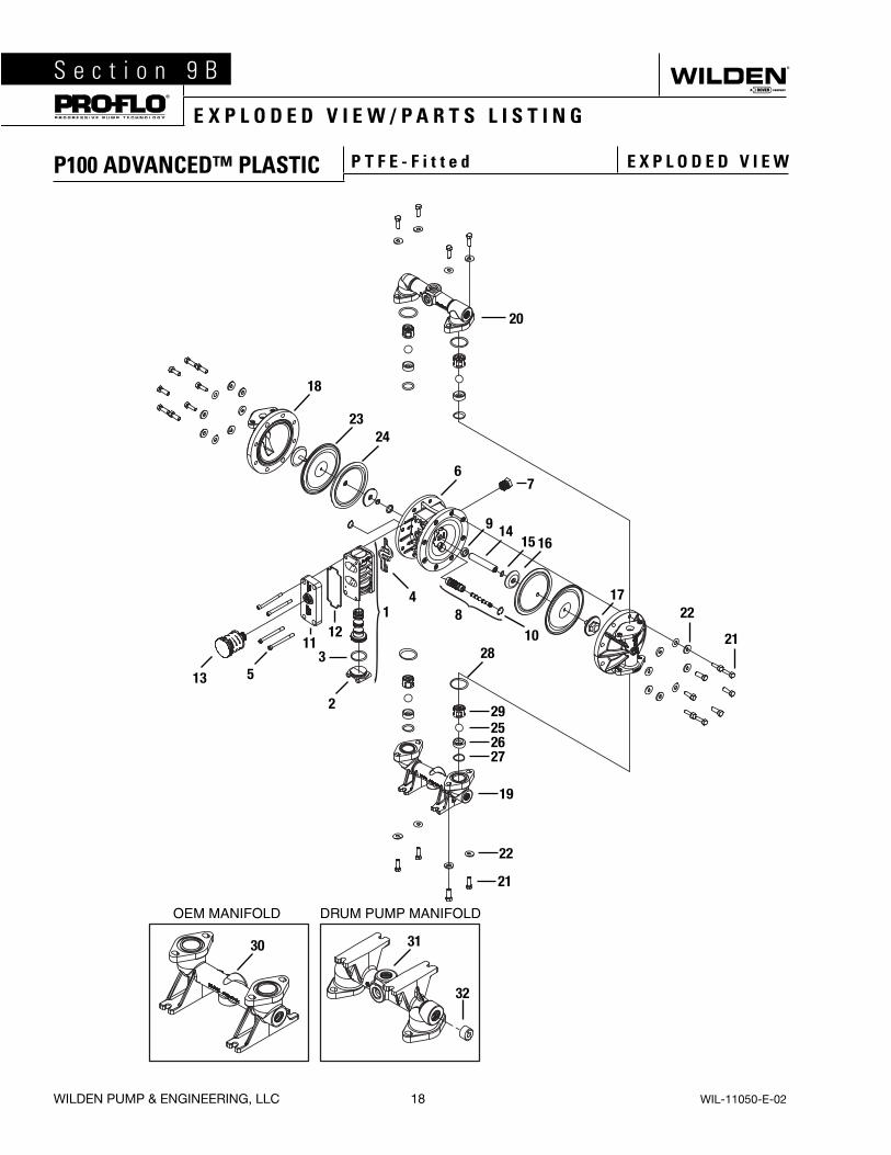
P100 ADVANCED™ PLASTIC P T F E - F i t t e d E X P L O D E D V I E W

WIL-11050-E-02 19 WILDEN PUMP & ENGINEERING, LLC
®
E X P L O D E D V I E W / P A R T S L I S T I N G
Item Part Description
Qty.Per
Pump
P100/PPPPP
P100/PPPPP/0502
P100/KKPPP
P100/KKPPP/0502
P/N P/N P/N P/N
1 Pro-Flo® Air Valve Assembly1 1 01-2010-20 01-2010-20 01-2010-20 01-2010-20
2 End Cap 1 01-2332-20 01-2332-20 01-2332-20 01-2332-20
3 O-Ring, End Cap 1 01-2395-52 01-2395-52 01-2395-52 01-2395-52
4 Gasket, Air Valve 1 01-2615-52 01-2615-52 01-2615-52 01-2615-52
5 Screw, HSHC, Air Valve 1/4-20 4 01-6001-03 01-6001-05 01-6001-03 01-6001-05
6 Center Section Assembly 1 01-3141-20 01-3141-20 01-3141-20 01-3141-20
7 Bushing, Reducer 1 01-6950-20 01-6950-20 01-6950-20 01-6950-20
8 Removable Pilot Sleeve Assembly 1 01-3880-99 01-3880-99 01-3880-99 01-3880-99
9 Glyd™ Ring II 2 01-3220-55 01-3220-55 01-3220-55 01-3220-55
10 Retaining Ring 2 00-2650-03 00-2650-03 00-2650-03 00-2650-03
11 Muffler Plate 1 01-3181-20 01-3181-20 01-3181-20 01-3181-20
12 Gasket, Muffler Plate 1 01-3505-52 01-3505-52 01-3505-52 01-3505-52
13 Muffler 1 02-3510-99 02-3510-99 02-3510-99 02-3510-99
14 Shaft, Pro-Flo® 1 01-3810-03 01-3810-03 01-3810-03 01-3810-03
15 Disc Spring 2 01-6802-08 01-6802-08 01-6802-08 01-6802-08
16 Inner Piston 2 01-3711-08 01-3711-08 01-3711-08 01-3711-08
17 Outer Piston 2 01-4570-20-500 01-4570-20-500 01-4570-21-500 01-4570-21-500
18 Liquid Chamber 2 01-5005-20 01-5005-20 01-5005-21 01-5005-21
19 Inlet Manifold 1 01-5095-20 01-5095-20 01-5095-21 01-5095-21
20 Discharge Manifold 1 01-5035-20 01-5035-20 01-5035-21 01-5035-21
21 Bolt, 5/16-18 X 1-3/8 24 08-6100-03 08-6100-05 08-6100-03 08-6100-05
22 Washer 24 01-6732-03 01-6732-05 01-6732-03 01-6732-05
23 PTFE Primary Diaphragm 2 01-1010-55 01-1010-55 01-1010-55 01-1010-55
24 Neoprene Backup Diaphragm 2 01-1060-51 01-1060-51 01-1060-51 01-1060-51
25 Valve Ball 4 01-1080-55 01-1080-55 01-1080-55 01-1080-55
26 Valve Seat 4 01-1125-20 01-1125-20 01-1125-21 01-1125-21
27 Valve Seat O-Ring 4 01-1205-60 01-1205-60 01-1205-60 01-1205-60
28 Manifold O-Ring 4 05-1370-60 05-1370-60 05-1370-60 05-1370-60
29 Ball Cage 4 01-5355-20 01-5355-20 01-5355-21 01-5355-21
30 OEM Manifold 1 01-5097-20 01-5097-20 01-5097-21 01-5097-21
31 Drum Pump Manifold (NPT only) 1 01-5094-20 01-5094-20 01-5094-21 01-5094-21
32 Pipe Plug 1 01-7010-20 01-7010-20 01-7010-21 01-7010-21
1Air Valve Assembly includes items 2 and 3.*Refer to corresponding elastomer chart in Section 10.
0502 Specialty Code = PTFE - Coated Hardware0680 Specialty Code = OEM Specific Inlet Manifold0790 Specialty Code = Drum Pump Inlet Manifold
All boldface items are primary wear parts.
P100 ADVANCED™ PLASTIC P T F E - F i t t e d P A R T S L I S T I N G
WILDEN PUMP & ENGINEERING, LLC 20 WIL-11050-E-02
S e c t i o n 1 0®
E L A S T O M E R O P T I O N S
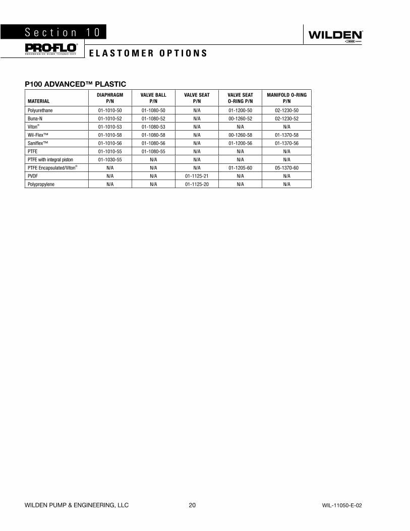
P100 ADVANCED™ PLASTIC
MATERIALDIAPHRAGM
P/NVALVE BALL
P/NVALVE SEAT
P/NVALVE SEATO-RING P/N
MANIFOLD O-RINGP/N
Polyurethane 01-1010-50 01-1080-50 N/A 01-1200-50 02-1230-50
Buna-N 01-1010-52 01-1080-52 N/A 00-1260-52 02-1230-52
Viton® 01-1010-53 01-1080-53 N/A N/A N/A
Wil-Flex™ 01-1010-58 01-1080-58 N/A 00-1260-58 01-1370-58
Saniflex™ 01-1010-56 01-1080-56 N/A 01-1200-56 01-1370-56
PTFE 01-1010-55 01-1080-55 N/A N/A N/A
PTFE with integral piston 01-1030-55 N/A N/A N/A N/A
PTFE Encapsulated/Viton® N/A N/A N/A 01-1205-60 05-1370-60
PVDF N/A N/A 01-1125-21 N/A N/A
Polypropylene N/A N/A 01-1125-20 N/A N/A
Item # Serial #
Company Where Purchased
Company Name
Industry
Name Title
Street Address
City State Postal Code Country
Telephone Fax E-mail Web Address
Number of pumps in facility? Number of Wilden pumps?
Types of pumps in facility (check all that apply): Diaphragm Centrifugal Gear Submersible Lobe
Other
Media being pumped?
How did you hear of Wilden Pump? Trade Journal Trade Show Internet/E-mail Distributor
Other
P U M P I N F O R M AT I O N
PLEASE PRINT OR TYPE AND FAX TO WILDEN
YO U R I N F O R M AT I O N
ONCE COMPLETE, FAX TO (909) 783-3440
NOTE: WARRANTY VOID IF PAGE IS NOT FAXED TO WILDEN
WILDEN PUMP & ENGINEERING, LLC
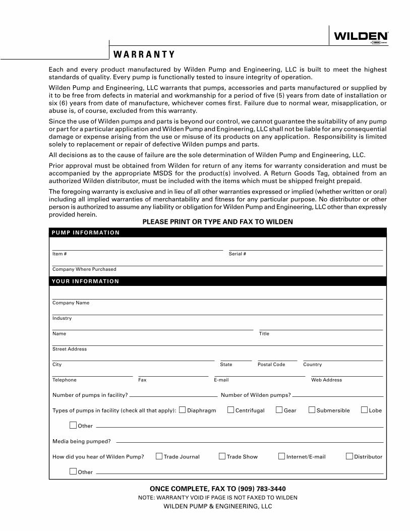
W A R R A N T YEach and every product manufactured by Wilden Pump and Engineering, LLC is built to meet the highest standards of quality. Every pump is functionally tested to insure integrity of operation.
Wilden Pump and Engineering, LLC warrants that pumps, accessories and parts manufactured or supplied by it to be free from defects in material and workmanship for a period of five (5) years from date of installation or six (6) years from date of manufacture, whichever comes first. Failure due to normal wear, misapplication, or abuse is, of course, excluded from this warranty.
Since the use of Wilden pumps and parts is beyond our control, we cannot guarantee the suitability of any pump or part for a particular application and Wilden Pump and Engineering, LLC shall not be liable for any consequential damage or expense arising from the use or misuse of its products on any application. Responsibility is limited solely to replacement or repair of defective Wilden pumps and parts.
All decisions as to the cause of failure are the sole determination of Wilden Pump and Engineering, LLC.
Prior approval must be obtained from Wilden for return of any items for warranty consideration and must be accompanied by the appropriate MSDS for the product(s) involved. A Return Goods Tag, obtained from an authorized Wilden distributor, must be included with the items which must be shipped freight prepaid.
The foregoing warranty is exclusive and in lieu of all other warranties expressed or implied (whether written or oral) including all implied warranties of merchantability and fitness for any particular purpose. No distributor or other person is authorized to assume any liability or obligation for Wilden Pump and Engineering, LLC other than expressly provided herein.