p-n junction under forward biasee.sc.edu/personal/faculty/simin/elct566/07... · diffusion current...
TRANSCRIPT
1
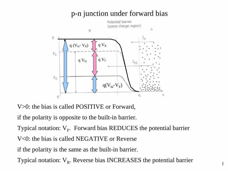
p-n junction under forward bias
V>0: the bias is called POSITIVE or Forward,
if the polarity is opposite to the built-in barrier.
Typical notation: VF. Forward bias REDUCES the potential barrier
V<0: the bias is called NEGATIVE or Reverse
if the polarity is the same as the built-in barrier.
Typical notation: VR. Reverse bias INCREASES the potential barrier
qV
qVo - qV
=qVo
q (Vbi- VR)
q Vbi q VF
q VR
q(Vbi-VF)

2
0
biqVkTp n
p p
V =0; The electron concentration on the p-side: n n e
Also n n,
−=
=
0
bi
biqV qV qV
kT kTp n p
V >0; New barrier height = qV - qV.
n n e n e−
−= =
Electron injection
qV
qVo - qV
=qVo
q (Vbi- VR)
q Vbi q VF
q VR
q(Vbi-VF)
(equilibrium electron concentration on the p-side) because the junction is in equilibrium

3
In the equilibrium
0
0biqV kTn
p
p ep
/−=
Under forward bias VF, the barrier decreases by qVF:
0biq V V kTn
p
pe
p( ) /− −=
Dividing (2) by (1):
0
qV kTn
n
p ep
/=
The concentration of injected holes exponentially increases with the forward voltage
(2)
(1)
(3)
Hole injection
0qV kT
n np p e /=

4
Summary of carrier injection under forward bias
qV
qVo - qV
=qVo
xn0 -xp0
The change in the electron concentration in the p-region:
0 0 1qV kTp p p pn n n n e /( )∆ = − = −
0 0 1qV kTn n n np p p p e /( )∆ = − = −
The change in the hole concentration in the n-region:
0qV kT
p pn n × e /=
0qV kT
n np p × e /=
Injected electron and hole concentrations:

5
Forward bias is applied: VF>0.
As compared to equilibrium conditions, much more electrons can overcome the barrier.
Electrons are injected into the p-side.
Injected electrons recombine with holes.
To compensate the loss, more electrons and holes are pulled from the n- and p-contacts
correspondingly.
qV
qVo - qV
=qVoq Vbi q VF
Carrier injection and forward current mechanism in p-n junction
6
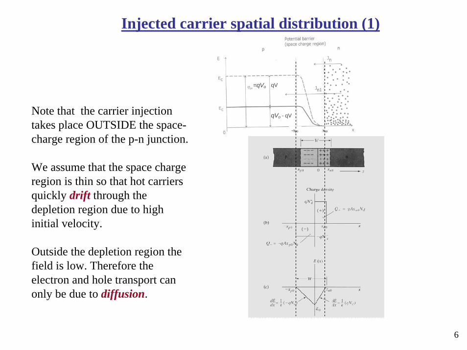
Note that the carrier injection takes place OUTSIDE the space-charge region of the p-n junction.
We assume that the space charge region is thin so that hot carriers quickly drift through the depletion region due to high initial velocity.
Outside the depletion region the field is low. Therefore the electron and hole transport can only be due to diffusion.
qV
qVo - qV
=qVo
xn0 -xp0
Injected carrier spatial distribution (1)

7
The injected carriers diffuse into n- and p-portions of the junctions and RECOMBINE along with DIFFUSION;
Space-Charge region
Space-Charge region
Injected carrier spatial distribution (2)
8
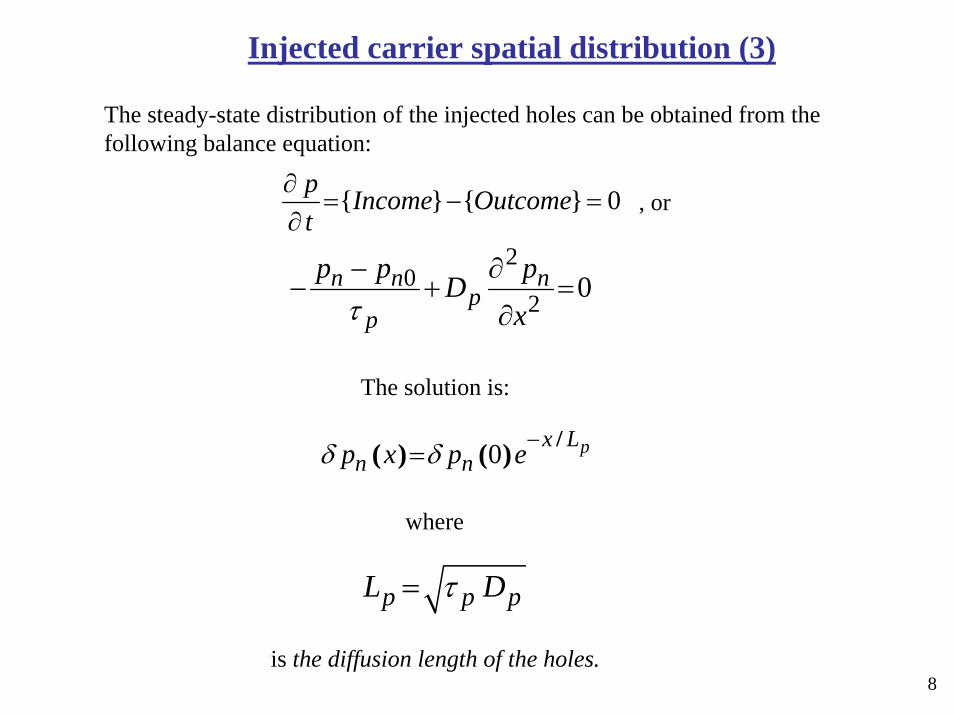
The steady-state distribution of the injected holes can be obtained from the following balance equation:
0}{}{ =−=∂∂ OutcomeIncome
tp
, or
The solution is:
where
is the diffusion length of the holes.
20
2 0n n np
p
p p pDxτ
− ∂− + =
∂
0 px Ln np x p e /( ) ( )δ δ −
=
p p pL Dτ=
Injected carrier spatial distribution (3)
9
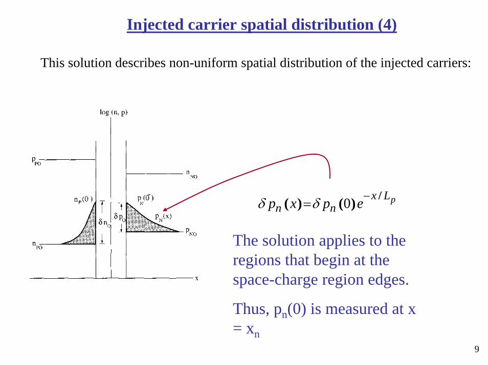
This solution describes non-uniform spatial distribution of the injected carriers:
The solution applies to the regions that begin at the space-charge region edges.
Thus, pn(0) is measured at x = xn
0 px Ln np x p e /( ) ( )δ δ −
=
Injected carrier spatial distribution (4)
10
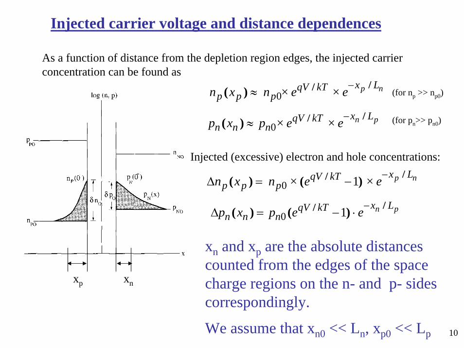
As a function of distance from the depletion region edges, the injected carrier concentration can be found as
xn and xp are the absolute distances counted from the edges of the space charge regions on the n- and p- sides correspondingly.
We assume that xn0 << Ln, xp0 << Lp
xp xn
0 1 p nx LqV kTp p pn x n × e × e //( ) ( ) −
∆ = −
0 1 n px LqV kTn n np x p e e //( ) ( ) −∆ = − ⋅
Injected carrier voltage and distance dependences
0p nx LqV kT
p p pn x n × e × e //( ) −≈
0n px LqV kT
n n np x p × e × e //( ) −≈
Injected (excessive) electron and hole concentrations:
(for np >> np0)
(for pn>> pn0)
11
Recombination current of the forward biased p-n junction
0 1 p nx LqV kTp p pn x n × e × e //( ) ( ) −
∆ = −
0 1 n px LqV kTn n np x p e e //( ) ( ) −∆ = − ⋅
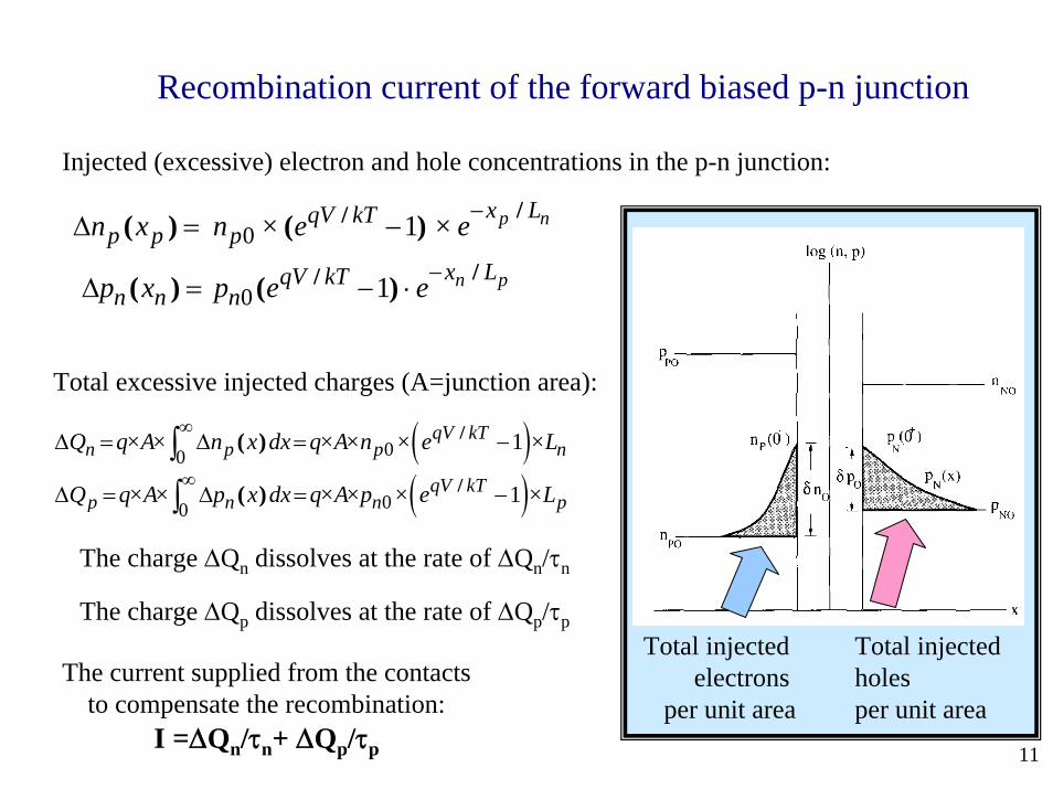
Injected (excessive) electron and hole concentrations in the p-n junction:
Total excessive injected charges (A=junction area):
( )001qV kT
n p p nQ q×A× n x dx q×A×n × e ×L/( )∞
∆ = ∆ = −∫( )00
1qV kTp n n pQ q×A× p x dx q×A×p × e ×L/( )
∞∆ = ∆ = −∫
The charge ∆Qn dissolves at the rate of ∆Qn/τn
The charge ∆Qp dissolves at the rate of ∆Qp/τp
The current supplied from the contacts to compensate the recombination:
I =∆Qn/τn+ ∆Qp/τp
Total injected electrons
per unit area
Total injected holes per unit area
12
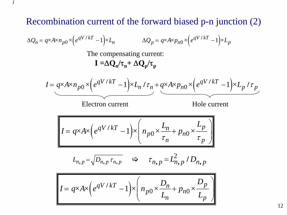
Recombination current of the forward biased p-n junction (2)
( )0 1qV kTn p nQ q×A×n × e ×L/∆ = − ( )0 1qV kT
p n pQ q×A×p × e ×L/∆ = −
The compensating current: I =∆Qn/τn+ ∆Qp/τp
I
( ) ( )0 01 1qV kT qV kTp n n n p pI q×A×n × e ×L q×A×p × e ×L/ // /τ τ= − + −
Electron current Hole current
( ) 0 01 pqV kT np n
n p
LLI q×A× e × n × p ×/
τ τ
⎛ ⎞= − +⎜ ⎟⎜ ⎟
⎝ ⎠
n p n p n pL D, , ,τ= 2n p n p n pL D, , ,/τ =
( ) 0 01 pqV kT np n
n p
DDI q×A× e × n × p ×
L L/ ⎛ ⎞
= − +⎜ ⎟⎜ ⎟⎝ ⎠
13
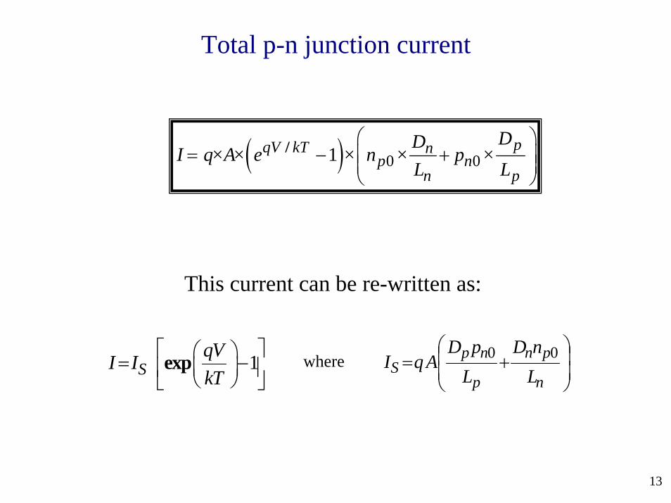
1SqVI IkT
exp⎡ ⎤⎛ ⎞= −⎜ ⎟⎢ ⎥⎝ ⎠⎣ ⎦ ⎟
⎟⎠
⎞⎜⎜⎝
⎛+=
n
pn
p
npS L
nDLpD
AqI 00
This current can be re-written as:
where
Total p-n junction current
( ) 0 01 pqV kT np n
n p
DDI q×A× e × n × p ×
L L/ ⎛ ⎞
= − +⎜ ⎟⎜ ⎟⎝ ⎠
14
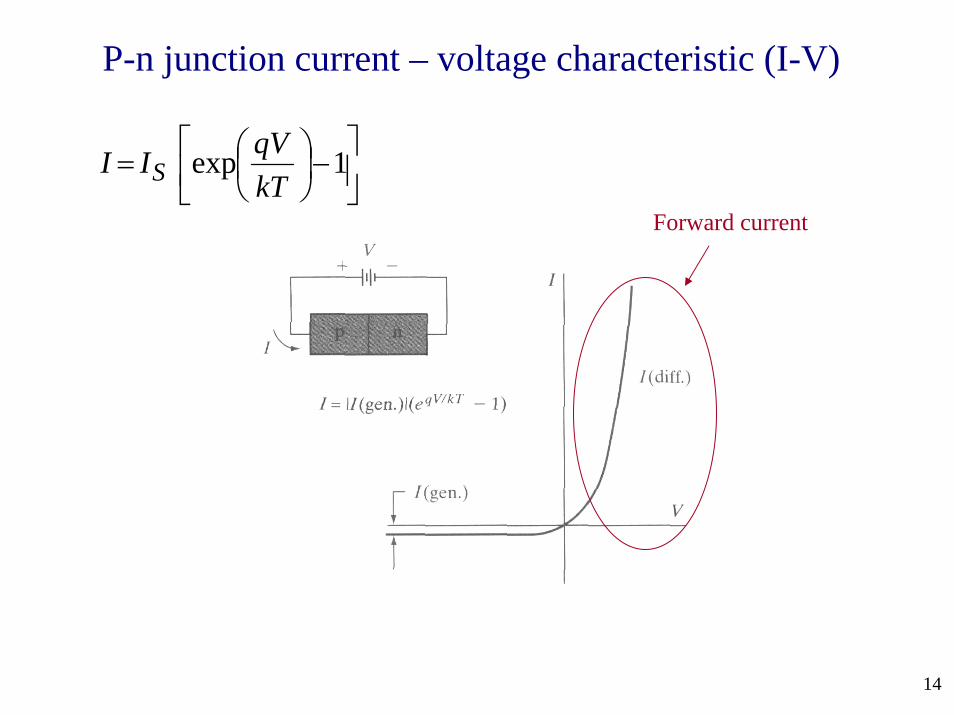
⎥⎦
⎤⎢⎣
⎡−⎟⎠⎞
⎜⎝⎛= 1exp
kTqVII S
Forward current
P-n junction current – voltage characteristic (I-V)
15
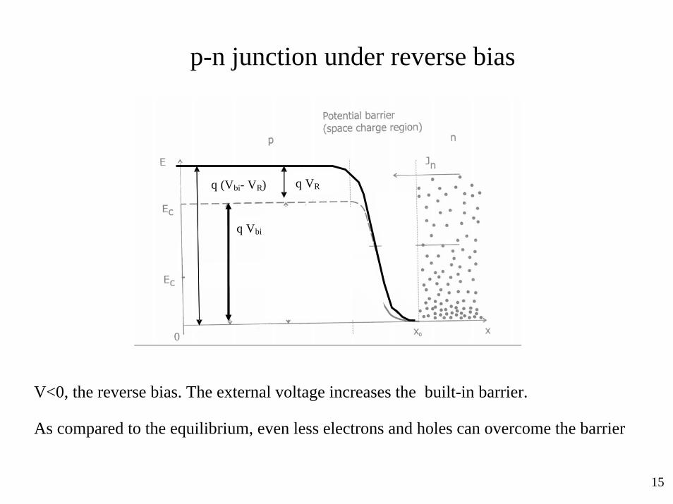
p-n junction under reverse bias
V<0, the reverse bias. The external voltage increases the built-in barrier.
As compared to the equilibrium, even less electrons and holes can overcome the barrier
qV
qVo - qV
=qVo
q (Vbi- VR)
q Vbi F
q VR

16
0 0qV kT
p p pn n e n/= <<
The concentrations of injected electrons and holes exponentially decrease with the reverse voltage
The concentrations of holes in the n-region and electrons in the p-region:
0 0qV kT
n n np p e p/= << (V < 0)
(V < 0)
17
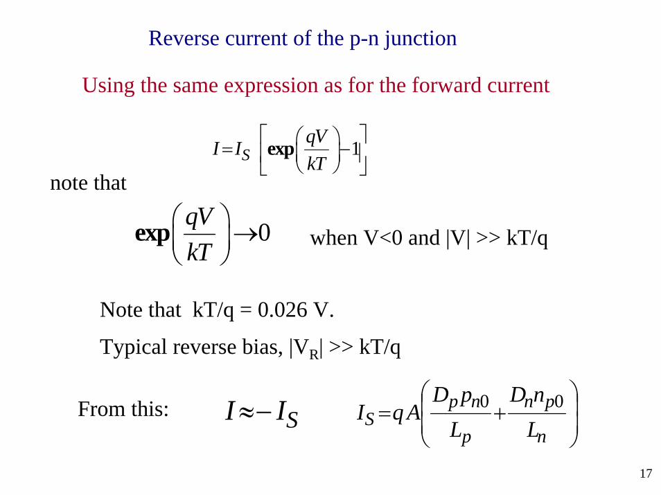
Using the same expression as for the forward current
⎟⎟⎠
⎞⎜⎜⎝
⎛+=
n
pn
p
npS L
nDLpD
AqI 00
Reverse current of the p-n junction
note that1S
qVI IkT
exp⎡ ⎤⎛ ⎞= −⎜ ⎟⎢ ⎥⎝ ⎠⎣ ⎦
0qVkT
exp⎛ ⎞→⎜ ⎟⎝ ⎠
SI I≈−From this:
when V<0 and |V| >> kT/q
Note that kT/q = 0.026 V.
Typical reverse bias, |VR| >> kT/q
18
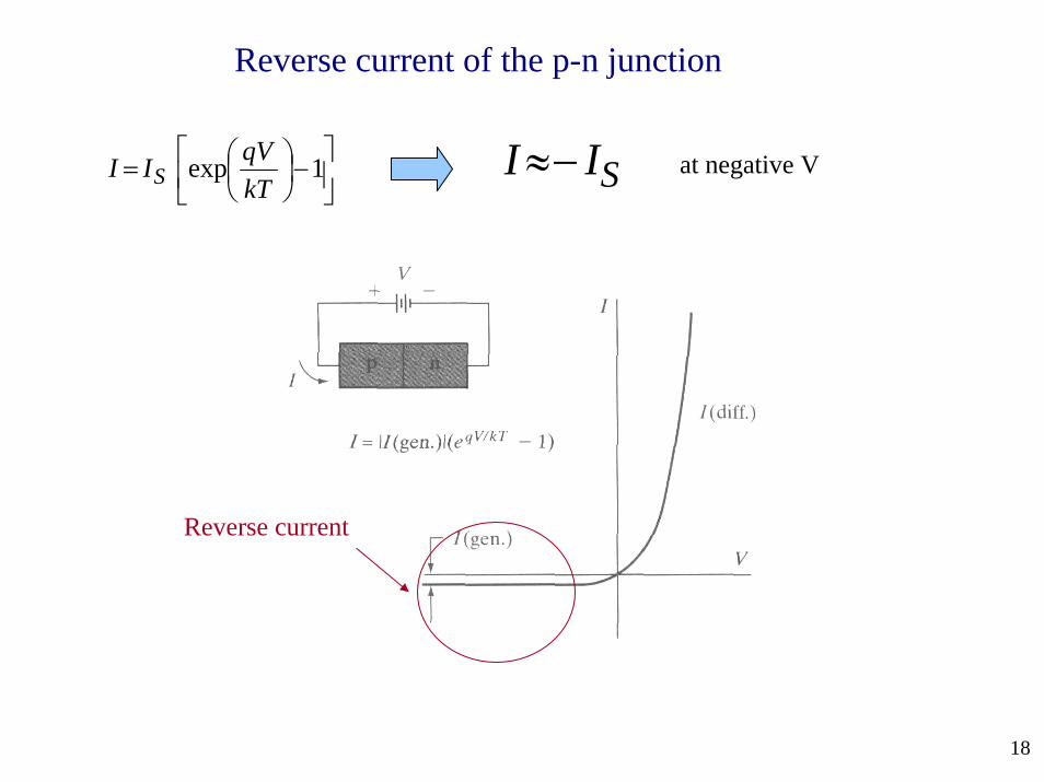
⎥⎦
⎤⎢⎣
⎡−⎟⎠⎞
⎜⎝⎛= 1exp
kTqVII S
Reverse current
SI I≈− at negative V
Reverse current of the p-n junction
19
⎥⎦
⎤⎢⎣
⎡−⎟⎠⎞
⎜⎝⎛= 1exp
kTqVII S
IS
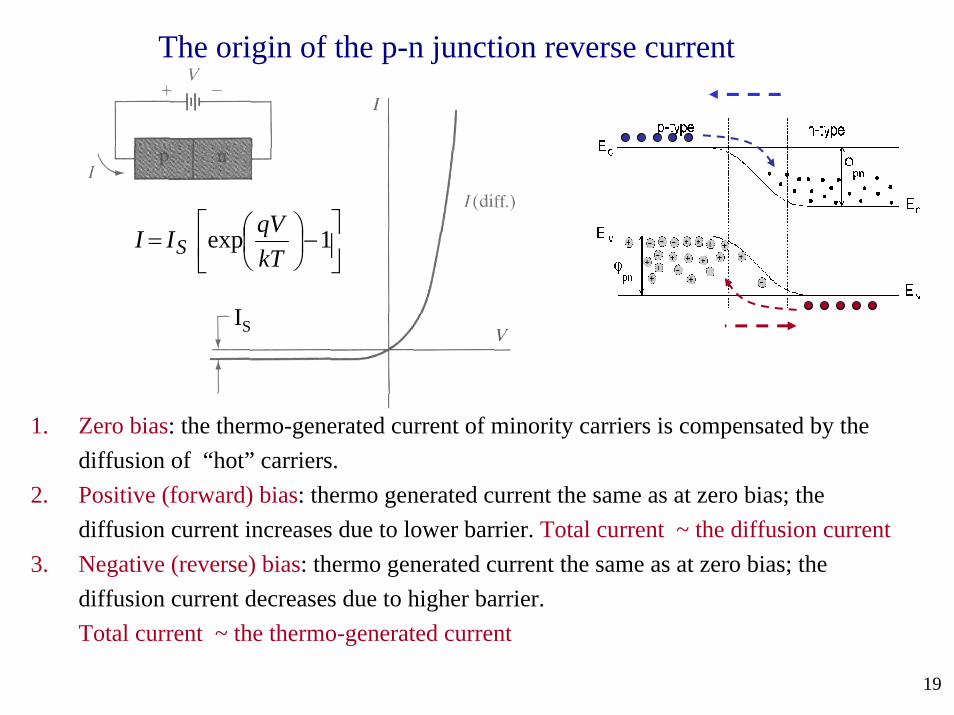
1. Zero bias: the thermo-generated current of minority carriers is compensated by the diffusion of “hot” carriers.
2. Positive (forward) bias: thermo generated current the same as at zero bias; the diffusion current increases due to lower barrier. Total current ~ the diffusion current
3. Negative (reverse) bias: thermo generated current the same as at zero bias; the diffusion current decreases due to higher barrier. Total current ~ the thermo-generated current
The origin of the p-n junction reverse current

20
Electron – hole flow balance in p-n junction